YASKAWA SPRiPM. Drive Package Quick Start Guide
|
|
|
- Johnathan Bryan
- 5 years ago
- Views:
Transcription


1 YASKAWA SPRiPM Drive Package Quick Start Guide Type: SPA Models: 400 V Class: 1.5 to 45 kw To properly use the product, read this manual thoroughly and retain for easy reference, inspection, and maintenance. Ensure the end user receives this manual. MANUAL NO. TOEP C A YASKAWA ELECTRIC TOEP C A YASKAWA AC Drive - SPRiPM Drive Package - Quick Start Guide 1
2 Copyright 2015 YASKAWA ELECTRIC CORPORATION. All rights reserved. No part of this publication may be reproduced, stored in a retrieval system, or transmitted, in any form, or by any means, mechanical, electronic, photocopying, recording, or otherwise, without the prior written permission of Yaskawa. No patent liability is assumed with respect to the use of the information contained herein. Moreover, because Yaskawa is constantly striving to improve its high-quality products, the information contained in this manual is subject to change without notice. Every precaution has been taken in the preparation of this manual. Nevertheless, Yaskawa assumes no responsibility for errors or omissions. Neither is any liability assumed for damages resulting from the use of the information contained in this publication. 2 YASKAWA ELECTRIC TOEP C A YASKAWA AC Drive - SPRiPM Drive Package - Quick Start Guide
3 Table of Contents 1 SAFETY INSTRUCTIONS AND GENERAL WARNINGS MECHANICAL INSTALLATION ELECTRICAL INSTALLATION KEYPAD OPERATION START UP PARAMETER TABLE TROUBLESHOOTING SAFE DISABLE INPUT FUNCTION UL STANDARDS YASKAWA ELECTRIC TOEP C A YASKAWA AC Drive - SPRiPM Drive Package - Quick Start Guide 3
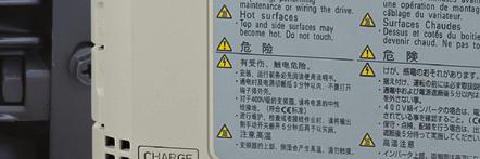
4 CIMR-AA2A0021FAA 200V 3Phase 5.5kW/3.7kW S/N: WARNING Risk of electric shock. Read manual before installing. Wait 5 minutes for capacitor discharge after disconnecting power supply. To conform to requirements, make sure to ground the supply neutral for 400V class. After opening the manual switch between the drive and motor, please wait 5 minutes before inspecting, performing maintenance or wiring the drive. Hot surfaces Top and Side surfaces may become hot. Do not touch. DIGITAL OPERATOR JVOP-180 F1 ESC RESET RUN F2 LO RE ALM ENTER STOP AVERTISSMENT NPJT Risque de décharge électrique. Lire le manuel avant l'installation. Attendre 5 minutes après la coupure de l'alimentation, pour permettre la décharge des condensateurs. Pour répondre aux exigences, s assurer que le neutre soit relié à la terre, pour la série 400V. Après avoir déconnécte la protection entre le driver et le moteur, veuillez patienter 5 minutes avain d effectuer une opération de montage ou de câblage du variateur. Surfaces Chaudes Dessus et cotés du boitier Peuvent devenir chaud. Ne Pas toucher V 5 1 Safety Instructions and General Warnings 1 Safety Instructions and General Warnings Yaskawa Electric supplies component parts for use in a wide variety of industrial applications. The selection and application of Yaskawa products remain the responsibility of the equipment designer or end user. Yaskawa accepts no responsibility for the way its products are incorporated into the final system design. Under no circumstances should any Yaskawa product be incorporated into any product or design as the exclusive or sole safety control. Without exception, all controls should be designed to detect faults dynamically and fail safely under all circumstances. All products designed to incorporate a component part manufactured by Yaskawa must be supplied to the end user with appropriate warnings and instructions as to the safe use and operation of that part. Any warnings provided by Yaskawa must be promptly provided to the end user. Yaskawa offers an express warranty only as to the quality of its products in conforming to standards and specifications published in the manual. NO OTHER WARRANTY, EXPRESS OR IMPLIED, IS OFFERED. Yaskawa assumes no liability for any personal injury, property damage, losses, or claims arising from misapplication of its products. Applicable Documentation The following manuals are available for SPRiPM drive packages: SPRiPM Drive Packages Quick Start Guide (this book) Read this manual first. This guide is packaged together with the product. It contains basic information required to install and wire the drive, in addition to an overview of fault diagnostics, maintenance, and parameter settings. Use the information in this book to prepare the drive for a trial run with the application and for basic operation. General Warnings W ARNING Read and understand this manual before installing, operating or servicing this drive. All warnings, cautions, and instructions must be followed. All work must be performed by qualified personnel. The drive must be installed according to this manual and local codes. Heed the safety messages in this manual. The operating company is responsible for any injuries or equipment damage resulting from failure to heed the warnings in this manual. The following conventions are used to indicate Safety messages in this manual: W ARNING Indicates a hazardous situation, which, if not avoided, could result in death or serious injury. CAUTION Indicates a hazardous situation, which, if not avoided, could result in minor or moderate injury. Indicates a property damage message. NOTICE 4 YASKAWA ELECTRIC TOEP C A YASKAWA AC Drive - SPRiPM Drive Package - Quick Start Guide
5 1 Safety Instructions and General Warnings Safety Warnings W ARNING Electrical Shock Hazard Do not attempt to modify or alter the drive in any way not explained in this manual. Yaskawa is not responsible for the damage caused by modification of the product made by the user. Failure to comply could result in death or serious injury from operation of damaged equipment. Do not touch any terminals before the capacitors have fully discharged. Failure to comply could result in death or serious injury. Before wiring terminals, disconnect all power to the equipment. The internal capacitor remains charged even after the power supply is turned off. The charge indicator LED will extinguish when the DC bus voltage is below 50 Vdc. To prevent electric shock, wait at least five minutes after all indicators are off and measure the DC bus voltage level to confirm safe level. Do not allow unqualified personnel to use equipment. Failure to comply could result in death or serious injury. Maintenance, inspection, and replacement of parts must be performed only by authorized personnel familiar with installation, adjustment, and maintenance of AC drives. Do not change wiring, remove covers, connectors or options cards, or attempt to service the drive with power applied to the drive. Failure to comply could result in death or serious injury. Disconnect all power to the drive and check for unsafe voltages before servicing. Always ground the motor-side grounding terminal. Improper equipment grounding could result in death or serious injury by contacting the motor case. Do not perform work on the drive while wearing loose clothing, jewelry or without eye protection. Failure to comply could result in death or serious injury. Remove all metal objects such as watches and rings, secure loose clothing, and wear eye protection before beginning work on the drive. Never short the output circuits of the drive. Do not short the output circuits of the drive. Failure to comply could result in death or serious injury. Make sure the protective earthing conductor complies with technical standards and local safety regulations. When an EMC filter is installed or with models CIMR-A4A0414 and larger, the leakage current exceeds 3.5 ma. Therefore according to IEC/EN automatic power supply interruption in case of discontinuity of the protective earthing conductor must be provided or a protective earthing conductor with a cross section of at least 10 mm 2 (Cu) or 16 mm 2 (Al) must be used. Use appropriate equipment for residual current monitoring/detection (RCM/RCD). This drive can cause a residual current with a DC component in the protective earthing conductor. Where a residual current operated protective or monitoring device is used for protection in case of direct or indirect contact, always use an RCM or RCD of type B according to IEC/EN Sudden Movement Hazard Stay clear of the motor during rotational Auto-Tuning. The motor may start operating suddenly. During automatic starting of equipment, the machine may start moving suddenly, which could result in death or serious injury. System may start unexpectedly upon application of power, resulting in death or serious injury. Clear all personnel from the drive, motor, and machine area before applying power. Secure covers, couplings, shaft keys, and machine loads before applying power to the drive. YASKAWA ELECTRIC TOEP C A YASKAWA AC Drive - SPRiPM Drive Package - Quick Start Guide 5
6 1 Safety Instructions and General Warnings W ARNING Fire Hazard Do not use an improper voltage source. Failure to comply could result in death or serious injury by fire. Verify that the rated voltage of the drive matches the voltage of the incoming power supply before applying power. Do not use improper combustible materials in drive installation, repair or maintenance. Failure to comply could result in death or serious injury by fire. Attach the drive or braking resistors to metal or other noncombustible material. Do not connect the AC power line to the output terminals of the drive. Failure to comply could result in death or serious injury by fire as a result of drive damage from line voltage application to output terminals. Do not connect AC line power to output terminals U, V, and W. Make sure that the power supply lines are connected to main circuit input terminals R/L1, S/L2, T/L3 (or R/L1 and S/ L2 for single-phase power). Tighten all terminal screws to the specified tightening torque. Loose electrical connections could result in death or serious injury by fire due to overheating of electrical connections. Crush Hazard Use a dedicated lifter when transporting the drive by a lifter. Improper lifter may cause the drive to drop, resulting in serious injury. Only allow qualified personnel to operate a crane or hoist to transport the drive. Failure to comply could result in death or serious injury from falling equipment. CAUTION Crush Hazard Do not carry the drive by the front cover. Failure to comply may result in minor or moderate injury from the main body of the drive falling. Burn Hazard Do not touch the heatsink or braking resistor hardware until a powered-down cooling period has elapsed. NOTICE Equipment Hazard Observe proper electrostatic discharge procedures (ESD) when handling the drive and circuit boards. Failure to comply may result in ESD damage to the drive circuitry. Never connect or disconnect the motor from the drive while the drive is outputting voltage. Improper equipment sequencing could result in damage to the drive. Do not perform a withstand voltage test on any part of the unit. Failure to comply could result in damage to the sensitive devices within the drive. Use power off resistance checks to determine shortcircuits. Do not operate damaged equipment. Failure to comply could result in further damage to the equipment. Do not connect or operate any equipment with visible damage or missing parts. 6 YASKAWA ELECTRIC TOEP C A YASKAWA AC Drive - SPRiPM Drive Package - Quick Start Guide
7 1 Safety Instructions and General Warnings NOTICE If a fuse is blown or equipment for residual current monitoring/detection (RCM/RCD) is tripped, check the wiring and the selection of the peripheral devices. Contact your supplier if the cause cannot be identified after checking the above. Do not restart the drive until 5 minutes passes and CHARGE lamp is OFF or immediately operate the peripheral devices if a fuse is blown or equipment for residual current monitoring/detection (RCM/RCD) is tripped. Check the wiring and the selection of peripheral devices to identify the cause. Contact your supplier before restarting the drive or the peripheral devices if the cause cannot be identified. For models CIMR-A4A0930 and 4A1200, make sure to install a fuse and equipment for residual current monitoring/detection (RCM/RCD). Failure to comply may result in serious damage to the facilities in case the drive is defected. Do not use unshielded cable for control wiring. Failure to comply may cause electrical interference resulting in poor system performance. Use shielded twisted-pair wires and ground the shield to the ground terminal of the drive. Do not carelessly connect parts or devices to the drives braking transistor terminals. Failure to comply could result in damage to the drive or braking circuit. Carefully review instruction manual TOBP C when connecting a braking option to the drive. Do not modify the drive circuitry. Failure to comply could result in damage to the drive and will void warranty. Yaskawa is not responsible for modification of the product made by the user. This product must not be modified. Check all the wiring to ensure that all connections are correct after installing the drive and connecting other devices. Failure to comply could result in damage to the drive. Improper application of devices on drive output circuits can damage the drive Do not connect unapproved LC or RC interference suppression filters, capacitors, ground fault circuits, or overvoltage protection devices to the drive. Fire Hazard Install adequate branch circuit short circuit protection per applicable codes. The drive is suitable for circuits capable of delivering not more than 100,000 RMS symmetrical Amperes, 240 Vac maximum (200 V Class) and 480 Vac maximum (400V Class). Inadequate branch short circuit protection damage or serious injury by fire. Precautions for CE Low Voltage Directive Compliance This drive has been tested according to European standard IEC/EN , and it fully complies with the Low Voltage Directive. The following conditions must be met to maintain compliance when combining this drive with other devices: Do not use drives in areas with pollution higher than severity 2 and overvoltage category 3 in accordance with IEC/ EN664. Ground the neutral point of the main power supply for 400 V Class drives. YASKAWA ELECTRIC TOEP C A YASKAWA AC Drive - SPRiPM Drive Package - Quick Start Guide 7
8 2 Mechanical Installation 2 Mechanical Installation Upon Receipt Perform the following tasks after receiving the drive: Inspect the drive for damage. If the drive appears damaged upon receipt, contact your supplier. Verify receipt of the correct model by checking the information on the nameplate. If you have received the wrong model, contact your supplier. Nameplate AC drive model Input specifications Output specifications Lot number Serial number MODEL : CIMR-AC4A0044AAA MAX APPLI. MOTOR : 22kW / 18,5kW REV : B INPUT : AC3PH V 50/60Hz 52A/44A OUTPUT : AC3PH 0-480V 0-400Hz 44A/39A MASS O / N : 8.3 kg : PRG : 2150 S / N : GL-COMPLIANT IND.CONT.EQ. 7J48 Normal Duty Amps / Heavy Duty Amps Software version Installation Environment FILE NO : E IP00 YASKAWA ELECTRIC CORPORATION MADE IN JAPAN 2-1 Kurosaki-shiroishi, Yahatanishi-Ku, Kitakyushu Japan <1> The address of the head office of Yaskawa Electric Corporation (responsible for product liability) is shown on the nameplate. For optimum performance life of the drive, install the drive in an environment that meets the conditions listed below. PASS Enclosure type <1> Environment Conditions Installation Area Indoors IP20/NEMA Type 1 enclosure: -10C to +40C IP00 enclosure: -10C to +50C Drive reliability improves in environments without wide temperature fluctuations. Ambient Temperature When using the drive in an enclosure panel, install a cooling fan or air conditioner in the area to ensure that the air temperature inside the enclosure does not exceed the specified levels. Do not allow ice to develop on the drive. Humidity 95% RH or less and free of condensation Storage Temperature -20C to +60C Install the drive in an area free from: oil mist and dust metal shavings, oil, water or other foreign materials radioactive materials Surrounding Area combustible materials (e.g., wood) harmful gases and liquids excessive vibration chlorides direct sunlight Altitude 1000 m, up to 3000 m with derating (for details, refer to the Technical Manual) Vibration 10 to 20 Hz at 9.8 m/s 2 20 to 55 Hz at 5.9 m/s 2 Orientation Install the drive vertically to maintain maximum cooling effects. 8 YASKAWA ELECTRIC TOEP C A YASKAWA AC Drive - SPRiPM Drive Package - Quick Start Guide
9 2 Mechanical Installation Installation Orientation and Spacing Always install the drive in an upright position. Leave space around the unit for proper cooling as shown in the figure on the right. 50 mm 120 mm Note: Several units can be installed closer together than shown in the figure by using Side-by-Side mounting. For details refer to the Technical Manual. 30 mm 30 mm 50 mm 120 mm Air Instructions on Installation Eye bolts are used to install the drive or to temporarily lift the drive when replacing it. The drive can be installed in an enclosure panel or on a wall. Do not leave the drive suspended by the wires in a horizontal or vertical position for long periods of time. Do not transport the drive over long distances. Read the following precautions and instructions before installing the drives. WARNING! Be sure to observe the following instructions and precautions. Failure to comply could result in minor or moderate injury and damage to the drive from falling equipment. Before using wires to suspend the drive vertically and horizontally, make sure that the drive front cover, terminal blocks and other drive components are securely fixed with screws. Do not subject the drive to vibration or impact greater than 1.96 m/s 2 (0.2 G) while it is suspended by the wires. Do not overturn the drive while it is suspended by the wires. Do not leave the drive suspended by the wires for long periods of time. YASKAWA ELECTRIC TOEP C A YASKAWA AC Drive - SPRiPM Drive Package - Quick Start Guide 9
10 2 Mechanical Installation Dimensions IP20/NEMA Type 1 Enclosure Drives Note: IP20/NEMA Type 1 Enclosure drives are equipped with a top protective cover. Removing this cover voids NEMA Type 1 protection but still keeps IP20 conformity. W1 W 4-d H2 H1 H 1.5 Figure 1 D D1 t1 Model CIMR-A Fig. Dimensions (mm) W H D W1 H1 H2 D1 t1 t2 d Weight (kg) 4A M A M A M A M A M A M A M A M6 8.3 IP00 Enclosure Drives W1 4-d H1 H t2 Model CIMR-A Fig. Dimensions (mm) Weight W H D W1 H1 H2 D1 t1 t2 d (kg) 4A M6 21 4A M A M6 36 4A M6 36 H2 Max 10 W Max 10 Figure 2 D t1 D1 10 YASKAWA ELECTRIC TOEP C A YASKAWA AC Drive - SPRiPM Drive Package - Quick Start Guide
11 3 Electrical Installation 3 Electrical Installation The figure below shows the main and control circuit wiring. Terminals -, +1, +2, B1, B2 are for connection options. Never connect power supply lines to these terminals DC reactor <1> (option) U X Jumper Thermal relay (option) Braking resistor (option) Three-phase power supply 200 to 400 V 50/60 Hz R/L1 S/L2 T/L3 Main Switch Fuse Multi-function digtial inputs (default setting) EMC Filter Forward Run / Stop Reverse Run / Stop External fault Fault reset Multi-speed step 1 Multi-speed step 2 Jog speed External Baseblock Sink / Source mode selection wire link (default: Sink) <2> R/L1 S/L2 T/L3 S1 S2 S3 S4 S5 S6 S7 S8 SN SC SP +24 V B1 B2 Main Circuit Control Circuit Drive Option card connectors CN5-C CN5-B CN5-A Terminal board jumpers and switches V Off PTC AI I DIP Switch S1 A2 Volt/Curr. Sel DIP Switch S2 On Term. Res. On/Off Jumper S3 H1, H2 Sink/Source Sel. DIP Switch S4 A3 Analog/PTC Input Sel Jumper S5 V FM/AM Volt./Curr. I U/T1 V/T2 W/T3 Ground Shielded Cable U V W Motor M FM N.O. N.C. AM Slide Switch S6 <4> DM+, DM- N.C./N.O. Multi-function analog/ pulse train inputs Safety Switch S2 S1 Open Safety relay / controller 2 kω MEMOBUS/Modbus comm. RS485/422 max kbps RP R + R S + S IG Safe Disable inputs H1 Wire jumper <3> +V Power supply Vdc, max. 20 ma A1 Analog Input 1 (Frequency Reference Bias) -10 to +10 Vdc (20 kω) A2 Analog Input 2 (Frequency Reference Bias) -10 to +10 Vdc (20 kω) 0 or 4 to 20 ma (250 Ω) A3 Analog Input 3 / PTC Input (Aux. frequency reference) AC -10 to +10 Vdc (20 kω) 0 V V H2 HC Shield ground terminal Pulse Train Input (max 32 khz) Power supply, Vdc, max. 20 ma Termination resistor (120 Ω, 1/2 W) DIP Switch S2 0 V 0 V MA MB MC M1 M2 M3 M4 M5 M6 MP AC FM AM AC E (G) Fault relay output 250 Vac, max. 1 A 30 Vdc, max 1 A (min. 5 Vdc, 10 ma) Multi-function relay output (During Run) 250 Vac, max. 1 A 30 Vdc, max 1 A (min. 5 Vdc, 10 ma) Multi-function relay output (Zero Speed) 250 Vac, max. 1 A 30 Vdc, max 1 A (min. 5 Vdc, 10 ma) Multi-function relay output (Speed Agree 1) 250 Vac, max. 1 A 30 Vdc, max 1 A (min. 5 Vdc, 10 ma) Multi-function pulse train output (Output frequency) 0 to 32 khz (2.2 kω) + FM AM + Multi-function analog output 1 (Output frequency) -10 to +10 Vdc (2mA) or 4 to 20 ma Multi-function analog output 2 (Output current) -10 to +10 Vdc (2mA) or 4 to 20 ma EDM (Safety Electronic Device Monitor) DM + <5> DM shielded line twisted-pair shielded line control circuit terminal main circuit terminal <1> Remove the jumper when installing a DC reactor. Models CIMR-A4A0058 through 0103 come with a built-in DC reactor. <2> Never short terminals SP and SN as doing so will damage the drive. <3> Disconnect the wire jumper between H1 - HC and H2 - HC when utilizing the Safe Disable input. <4> The slide switch S6 is available with terminal board ETC <5> Slide the switch S6 to select N.C. or N.O. as the state of the DM+ and DM- terminals for EDM output. YASKAWA ELECTRIC TOEP C A YASKAWA AC Drive - SPRiPM Drive Package - Quick Start Guide 11
12 3 Electrical Installation Wiring Specification Main Circuit Use the fuses and line filters listed in the table below when wiring the main circuit. Make sure not to exceed the given tightening torque values. Model CIMR-A EMC Filter Type Manufacturer Schaffner Manufacturer Block Main Fuse Manufacturer : Bussmann DC Power Supply Input <1> Fuse Fuse Holder Rated Short-circuit Type Breaking Qty. Type Qty. Current (ka) 4A0005 FS FB-40008A FWH-70B 4A0007 CR6L-50 2 CMS A0011 FS FB-40014A FWH-90B M4 M4 4A0018 FWH-80B FB-40025A CR6L-75 4A0023 FS FWH-100B 4 4A0031 FWH-125B CR6L CMS-5 2 FB-40044A M5 4A0038 FWH-200B M5 CR6L-150 4A0044 FS M6 FB-40060A 16 4A0058 CR6L-200 M8 4A0072 FB-40072A FWH-250A M8 FS CR6L <2> 25 4A0088 FB-40105A M10 4A0103 FS CR6L M8 <1> DC Power Supply Input is not available for UL standards. <2> Manufacturer does not recommend a specific fuse holder for this fuse. Contact Yaskawa or your nearest sales representative on fuse dimensions. CE Standards Compliance for DC Power Supply Input Recom. Motor Cable (mm 2 ) Main Circuit Terminal Sizes R/L1,S/L2, T/L3, U/T1, V/T2,W/T3,, +1, B1, B2 To meet CE standards, the following fuses should be installed. For details of connection diagram, refer to the following figure. For details of fuses and fuse holders, refer to the table on page 12. M4 M5 M6 M8 DC power supply (converter) Fuse + +1 A1000 U/T1 V/T2 W/T3 M Fuse +1 U/T1 V/T2 W/T3 M A1000 Note: 1. When connecting multiple drives together, make sure that each drive has its own fuse. If any one fuse blows, all fuses should be replaced. 2. For an AC power supply, refer to the connection diagram of Electrical Installation on page The recommended fuses and fuse holders are made by Fuji Electric. Tightening Torque Values Figure 11 Tighten the main circuit terminals using the torque values provided by the table below. Terminal Size M4 M5 M6 M8 Tightening Torque (N m) 1.2 to to to to YASKAWA ELECTRIC TOEP C A YASKAWA AC Drive - SPRiPM Drive Package - Quick Start Guide
13 3 Electrical Installation Control Circuit The control terminal board is equipped with screwless terminals. Always use wires within the specification listed below. For safe wiring it is recommended to use solid wires or flexible wires with ferrules. The stripping length respectively ferrule length should be 8 mm. EMC Filter Installation Wire Type Wire Size (mm 2 ) Solid 0.2 to 1.5 Flexible 0.2 to 1.0 Flexible with ferrule 0.25 to 0.5 This drive has been tested in accordance with European standards IEC/EN In order to comply to the EMC standards, wire the main circuit as described below. 1. Install an appropriate EMC noise filter to the input side. See the table in Main Circuit on page 12 or refer to the Technical Manual for details. 2. Place the drive and EMC noise filter in the same enclosure. 3. Use braided shield cable for the drive and motor wiring. 4. Remove any paint or dirt from ground connections for minimal ground impedance. 5. Install an DC reactor at drives smaller than 1 kw for compliance with the IEC/EN L3 L2 L1 PE Make sure the ground wire is grounded Enclosure panel Metal plate Grounding surface (remove any paint or sealant) E L3 L2 L1 Drive EMC noise filter Grounding surface (remove any paint or sealant) Ground plate (scrape off any visible paint) Cable clamp Motor cable (braided shield cable, max. 10 m) Motor Ground the cable shield Motor Wiring Connect the motor cable to drive terminals U/T1, V/T2 and W/T3. Use shielded motor cables only. Connect the motor shield to ground on the drive side and motor side. For more detailed instructions refer to the motor manual. YASKAWA ELECTRIC TOEP C A YASKAWA AC Drive - SPRiPM Drive Package - Quick Start Guide 13
14 3 Electrical Installation Main and Control Circuit Wiring Wiring the Main Circuit Input Consider the following precautions for the main circuit input. Use fuses recommended in Main Circuit on page 12 only. If using a ground fault circuit breaker, make sure that it can detect both DC and high frequency current. If using an input switch is used, make sure that the switch does not operate not more than once every 30 minutes. Use insulation caps when wiring the drive with crimp terminals. Take particular care to ensure that wiring does not touch neighboring terminals or the surrounding case. Use a DC reactor or AC reactor on the input side of the drive: To suppress harmonic current. To improve the power factor on the power supply side. When using an advancing capacitor switch. With a large capacity power supply transformer (over 600 kva). Wiring the Main Circuit Output Consider the following precautions for the output circuit wiring. Do not connect any other load than a 3 phase motor to the drives output. Never connect a power source to the drives output. Never short or ground the output terminals. Do not use phase correction capacitors. If using a contactor between the drive and motor, it should never be operated when the drive is outputting a voltage. Operating while there is voltage output can cause large peak currents, thus tripping the over current detection or damage the drive. Ground Connection Take the following precautions when grounding the drive. Never share the ground wire with other devices such as welding machines, etc. Always use a ground wire, that complies with electrical equipment technical standards. Keep ground wires as short as possible. Leakage current is caused by the drive. Therefore, if the distance between the ground electrode and the ground terminal is too long, potential on the ground terminal of the drive will become unstable. When using more than one drive, do not loop the ground wire. Control Circuit Wiring Precautions Consider the following precautions for wiring the control circuits. Separate control circuit wiring from main circuit wiring and other high-power lines. Separate wiring for control circuit terminals M1-M2, M3-M4, M5-M6, MA, MB, MC (contact output) from wiring to other control circuit terminals. For external control power supply use a UL Listed Class 2 power supply. Use twisted-pair or shielded twisted-pair cables for control circuits to prevent operating faults. Ground the cable shields with the maximum contact area of the shield and ground. Cable shields should be grounded on both cable ends. If flexible wires with ferrules are connected they might fit tightly into the terminals. To disconnect them, grasp the wire end with a pair of pliers, release the terminal using a straight-edge screw driver, turn the wire for about 45 and pull it gently out of the terminal. For details, refer to the Technical Manual. Use this procedure for removing the wire link between HC, H1 and H2 when the Safe Disable function is utilized. 14 YASKAWA ELECTRIC TOEP C A YASKAWA AC Drive - SPRiPM Drive Package - Quick Start Guide
15 3 Electrical Installation Main Circuit Terminals Terminal 400 V Class Model CIMR-A R/L1, S/L2, T/L3 R1/L11, S1/L21, T1/L31 Control Circuit Terminals Type 4A0005 to 4A0044 4A0058 to 4A0072 4A0088 to 4A0103 Main circuit power supply input not available Function Connects line power to the drive U/T1, V/T2, W/T3 Drive output Connects to the motor B1, B2 Braking resistor not available +2 DC reactor connection (+1, +2) (remove the shorting bar between +1, +1 and +2) DC power supply input (+1, ) +3 not available DC power supply input (+1, ) not available Available for connecting a braking resistor or a braking resistor unit option For connection of the drive to a DC power supply (terminals +1 and are not UL approved) of braking options connection of a DC reactor The figure below shows the control circuit terminal arrangement. The drive is equipped with screwless terminals. DC power supply input (+1, ) Braking transistor connection (+3, ) Grounding terminal S1 S6<1> S3 S2 E(G) HC H1 H2 DM+ DM- IG R+ R- S+ S- M3 M6 M4 S5 S4 V+ AC V- A1 A2 A3 FM AM AC MP RP AC S1 S2 S3 S4 S5 S6 S7 S8 SN SC SP M1 M2 M5 MA MB MC Use a straight-edge screwdriver with a blade width of max 2.5 mm and a thickness of max 0.6 mm to release the terminals <1> The slide switch S6 is available with terminal board ETC There are three DIP Switches and one Slide Switch and two jumpers, S1 to S6, located on the terminal board. S1 Terminal A2 Signal V I V I Current Voltage S2 RS422/485 Termination Resistor Off On S3 Safe Disable Input Sink/Source/External Supply Source Sink External 24 Vdc Power Supply PTC PTC S4 Terminal A3 Analog/PTC Input AI AI Analog Input PTC Input YASKAWA ELECTRIC TOEP C A YASKAWA AC Drive - SPRiPM Drive Package - Quick Start Guide 15
16 3 Electrical Installation S5 Terminal FM/AM Signal V I FM AM FM/AM: Voltage Output V FM AM FM: Current Output AM: Voltage Output I... N.O. S6 <1> Terminal DM+, DM- (N.C./N.O.) N.C. <1> The slide switch S6 is available with terminal board ETC Control Circuit Terminal Functions Type No. Terminal Name (Function) Function (Signal Level) Default Setting S1 Multi-function input 1 (Closed: Forward run, Open: Stop) S2 Multi-function input 2 (Closed: Reverse run, Open: Stop) S3 Multi-function input 3 (External fault, N.O.) Photocoupler S4 Multi-function input 4 (Fault reset) 24 Vdc, 8 ma S5 Multi-function input 5 (Multi-step speed Use the wire link between terminals SC and SN or SC and SP to select reference 1) between sinking, sourcing mode, and the power supply. Multi-Function Digital Inputs Safe Disable Inputs Analog Inputs / Pulse Train Input S6 Multi-function input 6 (Multi-step speed reference 2) S7 Multi-function input 7 (Jog reference) S8 Multi-function input 8 (External baseblock) SC Multi-function input common SN Multi-function input 0 V 24 Vdc power supply for digital inputs, 150 ma max (if no digital SP Multi-function input 24 Vdc input option DI-A3 is used) Never short terminals SP and SN as doing so will damage the drive. H1 Safe Disable input 1 24 Vdc, 8 ma One or both open: Drive output disabled Both closed: Normal operation Internal impedance: 3.3 k H2 Safe Disable input 2 Off time of at least 1 ms Disconnect the wire jumpers shorting terminals H1, H2, and HC to use the Safe Disable inputs. Set the S3 jumper to select between sinking, sourcing mode, and the power supply. HC Safe Disable function common Safe disable function common RP Multi-function pulse train input (Frequency reference) Input frequency range: 0 to 32 khz Signal Duty Cycle: 30 to 70% High level: 3.5 to 13.2 Vdc, low level: 0.0 to 0.8 Vdc Input impedance: 3 k +V Power supply for analog inputs 10.5 Vdc (max allowable current 20 ma) -V Power supply for analog inputs Vdc (max allowable current 20 ma) A1 Multi-function analog input 1 (Frequency reference bias) -10 to 10 Vdc, 0 to 10 Vdc (input impedance: 20 k) A2 A3 Multi-function analog input 2 (Frequency reference bias) Multi-function analog input 3 / PTC Input (Auxiliary frequency reference) AC Frequency reference common 0 V E (G) Ground for shielded lines and option cards -10 to 10 Vdc, 0 to 10 Vdc (input impedance: 20 k) 4 to 20 ma, 0 to 20 ma (input impedance: 250 ) Voltage or current input must be selected by DIP switch S1 and H to 10 Vdc, 0 to 10 Vdc (input impedance: 20 k) Use switch S4 on the control terminal board to select between analog input or PTC input. If PTC is selected, set H3-06 = E. 16 YASKAWA ELECTRIC TOEP C A YASKAWA AC Drive - SPRiPM Drive Package - Quick Start Guide
17 3 Electrical Installation Type No. Terminal Name (Function) Function (Signal Level) Default Setting Fault Relay Multi-Function Digital Output Monitor Output Safety Monitor Output MA MB MC M1 M2 M3 M4 M5 M6 N.O. N.C. output Fault output common Multi-function digital output (During run) Multi-function digital output (Zero speed) Multi-function digital output (Speed agree 1) NOTICE: The terminals HC, H1, H2 are used for the Safe Disable function. Do not remove the wire link between HC, H1, or H2 unless the Safe Disable function is used. Refer to Safe Disable Input Function on page 33 when using this function. NOTICE: The wiring length to the terminals HC, H1 and H2 should not exceed 30 m. 30 Vdc, 10 ma to 1 A; 250 Vac, 10 ma to 1 A Minimum load: 5 Vdc, 10 ma 30 Vdc, 10 ma to 1 A; 250 Vac, 10 ma to 1 A Minimum load: 5 Vdc, 10 ma 30 Vdc, 10 ma to 1 A; 250 Vac, 10 ma to 1 A Minimum load: 5 Vdc, 10 ma 30 Vdc, 10 ma to 1 A; 250 Vac, 10 ma to 1 A Minimum load: 5 Vdc, 10 ma MP Pulse train output (Output frequency) 32 khz (max) FM AM Analog monitor output 1 (Output frequency) Analog monitor output 2 (Output current) -10 to +10 Vdc, 0 to +10 Vdc, or 4 to 20 ma Use jumper S5 on the control terminal board to select between voltage or current output at terminals AM and FM. Set parameters H4-07 and H4-08 accordingly when changing the jumper setting. AC Monitor common 0 V DM+ DM- Safety monitor output Safety monitor output Outputs status of Safe Disable function. Closed when both Safe Disable channels are closed. The switch is initially set to N.C. Up to +48 Vdc 50 ma Slide the switch S6 to select N.C. or N.O. as the state of the DM+ and DM- terminals for EDM output. <1> <1> The slide switch S6 is available with terminal board ETC YASKAWA ELECTRIC TOEP C A YASKAWA AC Drive - SPRiPM Drive Package - Quick Start Guide 17
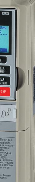
18 4 Keypad Operation 4 Keypad Operation Digital Operator and Keys The digital operator is used to program the drive, to start/stop it, and to display fault information. The LEDs indicate the drive status. DIGITAL OPERATOR JVOP-180 ALM F1 ESC F2 LO RE RESET RUN ENTER STOP Keys and Functions Key Name Function F1 F2 Function Key (F1, F2) The functions assigned to F1 and F2 vary depending on the menu that is currently displayed. The name of each function appears in the lower half of the display window. ESC RESET RUN ESC Key RESET Key RUN Key Up Arrow Key Returns to the previous display. Moves the cursor one space to the left. Pressing and holding this button will return to the Frequency Reference display. Moves the cursor to the right. Resets the drive to clear a fault situation. Starts the drive in the LOCAL mode. The Run LED is on, when the drive is operating the motor. flashes during deceleration to stop or when the frequency reference is 0. flashes quickly the drive is disabled by a DI, the drive was stopped using a fast stop DI or a run command was active during power up. Scrolls up to display the next item, selects parameter numbers and increments setting values. Down Arrow Key Scrolls down to display the previous item, selects parameter numbers and decrements setting values. STOP STOP Key Stops drive operation. ENTER LO RE ALM ENTER Key LO/RE Key ALM LED Light Enters parameter values and settings. Selects a menu item to move between displays. Switches drive control between the operator (LOCAL) and the control circuit terminals (REMOTE). The LED is on when the drive is in the LOCAL mode (operation from keypad). On: When the drive detects a fault. Flashing: When an alarm occurs. When ope is detected. When a fault or error occurs during Auto-Tuning. 18 YASKAWA ELECTRIC TOEP C A YASKAWA AC Drive - SPRiPM Drive Package - Quick Start Guide
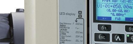
19 4 Keypad Operation Menu Structure and Modes The following illustration explains the operator keypad menu structure. Figure 1.1 Programming Mode <2> Drive Mode <1> - MODE - DRV Rdy FREF (OPR) U1-01= 0.00Hz U1-02= 0.00Hz LSEQ U1-03= 0.00A LREF JOG FWD FWD/REV - MODE - DRV Rdy Monitor Menu U1-01= 0.00Hz U1-02= 0.00Hz LSEQ U1-03= 0.00A LREF JOG FWD FWD/REV - MODE - PRG Modified Consts Modified X Parameters HELP HELP FWD DATA - MODE - PRG Quick Setting FWD DATA - MODE - PRG Programming HELP FWD DATA <4> -MONITR- DRV Rdy FREF (d1-01) U1-01= Hz Hz FWD -MONITR- DRV Rdy Output Freq U1-02 = 0.00Hz U1-03= 0.00A LSEQ U1-04= 0 LREF JOG FWD FWD/REV -MONITR- DRV Rdy Monitor U1-01= 0.00Hz U1-02= 0.00Hz LSEQ U1-03= 0.00A LREF JOG FWD FWD/REV -MONITR- DRV Rdy Fault Trace U2-01= oc U2-02= opr LSEQ U2-03= 0.00Hz LREF JOG FWD FWD/REV Initial Display <5> A1000 YASKAWA <3> -MONITR- DRV Rdy Frequency Ref U1-01 = 0.00Hz U1-02= 0.00Hz LSEQ U1-03= 0.00A LREF JOG FWD FWD/REV A1000 XXXVX.X/X.XkW XX.XX/XX.XXA <XXXXXXXXX> <6> - MODE - PRG Rdy Auto-Tuning AUTO HELP FWD DATA <1> Pressing RUN will start the motor. <2> Drive cannot operate the motor. <3> Flashing characters are shown as 0. <4> X characters are shown in this manual. The LCD Operator will display the actual setting values. <5> The Frequency Reference appears after the initial display which shows the product name. <6> The information that appears on the display will vary depending on the drive. YASKAWA ELECTRIC TOEP C A YASKAWA AC Drive - SPRiPM Drive Package - Quick Start Guide 19
20 5 Start Up 5 Start Up Drive Setup Procedure The illustration below shows the basic setup procedure. Each step is explained more detailed on the following pages. START Install and wire the drive as explained. Turn the power on. Set the control mode. Check motor codes E5-01. Set/check the basic parameters: * b1-01, b1-02 for frequency reference and RUN command source * H1-, H2-, H3-, H4-, H6- to configure the I/Os * Frequency reference values * C1-, C2- for Acceleration/Deceleration times and S-curves Run the motor without load, check the operation and verify, if the upper controller (e.g. PLC,...) commands to the drive work as desired. Connect the load, run the motor and check the operation Fine tune and set application parameters (e.g. PID,...) if necessary. Final check the operation and verify the settings. Drive is ready to run the application Power On Before turning on the power supply, Make sure all wires are connected properly. Make sure no screws, loose wire ends or tools are left in the drive. After turning the power on, the drive mode display should appear and no fault or alarm should be displayed. Control Mode (A1-02) There are more than three control modes available. Select the control mode that best suits the application the drive will control. Control Mode Open Loop Vector Control for PM <1> Advanced Open Loop Vector Control for PM <1> Parameter A1-02 = 5 Main Applications Derated torque-load applications employing permanent magnet motors (SPM, IPM) and energy savings. A1-02 = 6 This control mode can be used to operate an IPM motor for constant torque applications. <1> For explanations of these control modes, refer to the Technical Manual. 20 YASKAWA ELECTRIC TOEP C A YASKAWA AC Drive - SPRiPM Drive Package - Quick Start Guide
21 Motor Codes for E Start Up On delivery, the parameter E5-01 is pre-set for a 3000 rpm motor. Check the motor type code on the motor name plate and verify/set parameter E5-01 according to the table below. NOTICE: For motors with 1500 rpm the code has to be set individually. Motor Model Code Voltage [V] Rated Power [kw] E5-01 Setting o2-04 Setting Motors with 3000 rpm M071M015BM M071M022BM M071M040BM M090L055BM A 99 M100L075BM B 9A M100L110BM D 9C M112M150BM E 9D M132S185BM F 9E M132M220BM F M160M330BM A1 M180M370BM A2 Motors with 1500 rpm M071M015BJ M080M022BJ M090L040BJ M100L055BJ A 99 M112M075BJ B 9A M132S110BJ D 9C M132M150BJ E 9D M132M185BJ F 9E M160M220BJ F M160L300BJ A1 M180L370BJ A2 M180L450BJ A3 YASKAWA ELECTRIC TOEP C A YASKAWA AC Drive - SPRiPM Drive Package - Quick Start Guide 21
22 5 Start Up External Reference and Acceleration/ Deceleration Times Frequency Reference (b1-01) Set parameter b1-01 according to the frequency reference used. b1-01 Reference Source Frequency Reference Input 0 Operator keypad Set the frequency references in the d1- parameters and use digital inputs to switch over between different reference values. 1 Analog input Apply the frequency reference signal to terminal A1, A2, or A3. 2 Serial Comm. Serial Communications using the RS422/485 port 3 Option Card Communications option card 4 Pulse input Set the frequency reference at terminal RP using a pulse train signal. Run Command (b1-02) Set parameter b1-02 according to the run command used. b1-02 Reference Source Run Command Input 0 Operator keypad RUN and STOP keys on the operator 1 Multi-Function digital input Multi-Function digital input 2 Serial Comm. Serial Communications using the RS422/485 port 3 Option Card Communications option card Acceleration/ Deceleration Times and S-Curves There are four sets of acceleration and deceleration times which can be set in the C1- parameters. The default activated accel/decel times are C1-01/02. Adjust these times to the appropriate values required by the application. If necessary S-curves can be activated in the C2- parameters for softer accel/decel start and end. Reference and Run Source The drive has a LOCAL and a REMOTE mode. Status LOCAL REMOTE Description The Run/ Stop command and the frequency reference are entered at the operator keypad. The Run command source entered in parameter b1-02 or b1-16 and the frequency reference source entered in parameter b1-01 or b1-15 are used. If the drive is operated in the REMOTE mode, make sure that the correct sources for the frequency reference and run command are set in parameters b1-01/02 or b1-15/16 and that the drive is in the REMOTE mode. The LED in the LO/RE key indicates where the Run command is input from. LO/RE LED ON OFF Description Run command is issued from operator. Run command is issued from a different source than the operator. 22 YASKAWA ELECTRIC TOEP C A YASKAWA AC Drive - SPRiPM Drive Package - Quick Start Guide
23 5 Start Up I/O Setup Note: The default setting functions can be seen in the connection diagram on page 11. Multi-Function Digital Inputs (H1-) The function of each digital input can be assigned in the H1- parameters. Multi-Function Digital Outputs (H2-) The function of each digital output can be assigned in the H2- parameters. The setting value of these parameters consist of 3 digits, where the middle and right digit set the function and the left digit sets the output characteristics (0: Output as selected; 1: Inverse output). Multi-Function Analog Inputs (H3-) The function of each analog input can be assigned in the H3- parameters. Input A1 and A3 are set for -10 to +10 Vdc input. A2 is set for 4-20 ma input. NOTICE: If the input signal level of input A2 is switched between voltage and current, make sure that DIP switch S1 is in the correct position and parameter H3-09 is set up correctly. NOTICE: When using analog input A3 as PTC input, set DIP switch S4 to PTC and parameter H3-06 = E. Multi-Function Analog Outputs (H4-) Use the H4- parameters to set up the output value of the analog monitor outputs and to adjust the output signal levels. When changing signal levels in parameter H4-07/08, make sure jumper S5 is set accordingly. Test Run Perform the following steps to start up the machine after all parameter settings have been done. 1. Run the motor without load and check if all input, outputs and the sequence work as desired. 2. Connect the load to the motor. 3. Run the motor with load and make sure that there is no vibrations, hunting or motor stalling occurs. After taking the steps listed above, the drive should be ready to run the application and perform the basic functions. For special setups like PID control etc. refer to the Technical Manual. YASKAWA ELECTRIC TOEP C A YASKAWA AC Drive - SPRiPM Drive Package - Quick Start Guide 23
24 6 Parameter Table 6 Parameter Table This parameter table shows the most important parameters. Default settings are bold type. Refer to the Technical Manual for a complete list of parameters. No. Name Description Initialization Parameters A1-00 A1-01 A1-02 A1-03 b1-01 b1-02 b1-03 b1-04 Language Access Level Control Method 0: English 1: Japanese 2: German 3: French 4: Italian 5: Spanish 6: Portuguese 7: Chinese 8: Czech 9: Russian 10: Turkish 11: Polish 12: Greek Note: Languages No.8 to 12 can be selected from an LCD operator with version (REV) F or later. The version is listed on the back of the LCD operator. 0: View and set A1-01 and A1-04. U- parameters can also be viewed. 1: User Parameters (access to a set of parameters selected by the user, A2-01 to A2-32) 2: Advanced Access (access to view and set all parameters) 5: Open Loop Vector Control for PM 6: Advanced Open Loop Vector Control for PM 7: Closed Loop Vector Control for PM 0: No initialization 1110: User Initialize (parameter values must Initialize be stored using parameter o2-03) Parameters 2220: 2-wire initialization 3330: 3-wire initialization 5550: ope04 error reset Operation Mode Frequency Reference 1 Run Command 1 Stopping Method Reverse Operation 0: Digital operator 1: Analog input terminals 2: MEMOBUS/Modbus communications 3: Option PCB 4: Pulse input (terminal RP) 0: Digital operator 1: Digital input terminals 2: MEMOBUS/Modbus communications 3: Option PCB 0: Ramp to stop 1: Coast to stop 2: DC Injection Braking to stop 3: Coast with timer 9: Simple Positioning Stop 0: Reverse enabled. 1: Reverse disabled. No. Name Description b1-14 b2-01 b2-02 b2-03 b2-04 C1-01 C1-02 C1-03 to C1-08 C2-01 C2-02 C2-03 C2-04 C4-01 C4-02 C6-01 0: Standard Phase Order 1: Switch phase order (reverses the direction of the motor) DC Injection Braking DC Injection Braking Start Frequency DC Injection Braking Current DC Injection Braking Time at Start Sets the frequency at which DC Injection Braking starts when Ramp to stop (b1-03 = 0) is selected. Sets the DC Injection Braking current as a percentage of the drive rated current. Sets DC Injection Braking (Zero Speed Control when in CLV/PM) time at start. Disabled when set to 0.00 seconds. Note: This parameter is not available for AOLV/PM in models CIMR-A4A0930 and 4A1200. DC Injection Braking Time Sets DC Injection Braking time at stop. at Stop Acceleration/ Deceleration Acceleration Time 1 Deceleration Time 1 Acceleration/ Deceleration Time 2 to 4 S-Curve Characteristic at Accel Start S-Curve Characteristic at Accel End S-Curve Characteristic at Decel Start S-Curve Characteristic at Decel End Torque Compensation Gain Sets the time to accelerate from 0 to maximum frequency. Sets the time to decelerate from maximum frequency to 0. Set the accel/decel times 2 to 4 (set like C1-01/02). S-curve at acceleration start. S-curve at acceleration end. S-curve at deceleration start. S-curve at deceleration end. Torque Compensation Sets the gain for the automatic torque (voltage) boost function and helps to produce better starting torque. Used for motor 1. Torque Compensation Sets the torque compensation filter time. Primary Delay Time 1 Carrier Frequency Drive Duty 0: Heavy Duty (HD) for constant torque applications. 1: Normal Duty (ND) for variable torque applications. 24 YASKAWA ELECTRIC TOEP C A YASKAWA AC Drive - SPRiPM Drive Package - Quick Start Guide
25 6 Parameter Table No. Name Description C6-02 d1-01 to d1-16 d1-17 E5-01 <1> Carrier Frequency Frequency Reference 1 to 16 Jog Frequency Reference to 44 1: 2.0 khz 2: 5.0 khz 3: 8.0 khz 4: 10.0 khz 5: 12.5 khz 6: 15.0 khz 7: Swing PWM1 (Audible sound 1) 8: Swing PWM2 (Audible sound 2) 9: Swing PWM3 (Audible sound 3) A: Swing PWM4 (Audible sound 4) B to E: No setting possible F: User defined (determined by C6-03 through C6-05) Frequency Reference Sets the frequency reference for the drive. Setting units are determined by parameter o1-03. Sets the Jog frequency reference. Setting units are determined by parameter o1-03. Motor Codes SPRiPM 8 poles 1500 rpm 3000 rpm 400 V, 1.5 kw to 45 kw <1> Refer to Motor Codes for E5-01 on page 21 for a complete overview of available motor codes. Multi-Function Digital Inputs H1-01 to H1-08 Multi-Function Digital Input Terminal S1 to S8 Function Selects the function of terminals S1 to S8. Note: Major functions are listed at the end of the table. Multi-Function Digital Outputs H2-01 H2-02 H2-03 H2-06 Terminal M1- M2 function selection (Relay) Terminal M3- M4 function selection (Relay) Terminal M5- M6 function selection (Relay) Watt Hour Output Unit Set the function for the relay output M1- M2. Sets the function for the relay output M3- M4. Sets the function for the relay output M5- M6. Sets the output units for the watt hours when Watt Hour Pulse Output is selected as the digital output (H2-01, H2-02, or H2-03 = 39). Outputs a 200 ms pulse signal when the watt-hour counter increases by the units selected. 0: 0.1 kwh units 1: 1 kwh units 2: 10 kwh units 3: 100 kwh units 4: 1000 kwh units Note: Major functions are listed at the end of the table. No. Name Description H3-01 H3-02 H3-03 H3-04 H3-05 H3-06 H3-07 H3-08 H3-09 H3-10 H3-11 H3-12 H3-13 H3-14 H4-01 H4-02 Terminal A1 Signal Level Terminal A1 Function Terminal A1 Gain Setting Terminal A1 Bias Setting Terminal A3 Signal Level Terminal A3 Function Terminal A3 Gain Setting Terminal A3 Bias Setting Terminal A2 Signal Level Terminal A2 Function Terminal A2 Gain Setting Terminal A2 Bias Setting Analog Input Filter Time Constant Multi-Function Analog Inputs 0: 0 to 10 V 1: 10 to 10 V Sets the function of terminal A1. Sets the level of the input value selected in H3-02 when 10 V is input at terminal A1. Sets the level of the input value selected in H3-02 when 0 V is input at terminal A1. 0: 0 to 10 V 1: 10 to 10 V Sets the function of terminal A3. Sets the level of the input value selected in H3-06 when 10 V is input at terminal A3. Sets the level of the input value selected in H3-06 when 0 V is input at terminal A3. 0: 0 to 10 V 1: 10 to 10 V 2: 4 to 20 ma 3: 0 to 20 ma Note: Use DIP switch S1 to set input terminal A2 for a current or a voltage input signal. Sets the function of terminal A2. Sets the level of the input value selected in H3-10 when 10 V (20 ma) is input at terminal A2. Sets the level of the input value selected in H3-10 when 0 V (0 or 4 ma) is input at terminal A2. Sets a primary delay filter time constant for terminals A1, A2, and A3. Used for noise filtering. Determines which of the analog input terminals will be enabled or disabled when a digital input programmed for Analog input enable (H1- = C) is activated. The terminals other than the one set as the target Analog Input are not influenced by input signals. Terminal 1: Terminal A1 only Enable 2: Terminal A2 only 3: Terminals A1 and A2 only 4: Terminal A3 only 5: Terminals A1 and A3 6: Terminals A2 and A3 7: All terminals enabled Multi-Function Analog Inputs Multi-Function Analog Output Terminal FM Monitor Multi-Function Analog Output Terminal FM Gain Selects the data to be output through multifunction analog output terminal FM. Set the desired monitor parameter to the digits available in U-. For example, enter 103 for U1-03. Sets the signal level at terminal FM that is equal to 100% of the selected monitor value. YASKAWA ELECTRIC TOEP C A YASKAWA AC Drive - SPRiPM Drive Package - Quick Start Guide 25
YASKAWA AC Drive A1000
 YASKAWA AC Drive A1000 High Performance Vector Control Drive Quick Start Guide Type: CIMR-AC A Models: 200 V Class: 0.4 to 110 kw 400 V Class: 0.4 to 630 kw To properly use the product, read this manual
YASKAWA AC Drive A1000
 YASKAWA AC Drive A000 High Performance Vector Control Drive Quick Start Guide Type: CIMR-AC Models: 200 V Class: 0.4 to 55 kw 400 V Class: 0.4 to 90 kw To properly use the product, read this manual thoroughly
YASKAWA AC Drive A1000
 YASKAWA AC Drive A000 IP54 Ready Quick Start Guide Type: CIMR-AC4A WAA Models: 400 V Class: 8.5 to 90 kw To properly use the product, read this manual thoroughly and retain for easy reference, inspection,
YASKAWA AC Drive A1000
 YASKAWA AC Drive A1000 Crane Software Quick Start Guide Type: CIMR-AC A Models: 200 V Class: 0.4 to 110 kw 400 V Class: 0.4 to 315 kw To properly use the product, read this manual thoroughly and retain
YASKAWA AC Drive A1000
 YASKAWA AC Drive A000 IP23/54 Floor Standing Panel Quick Start Guide Type: A4 Models: 400 V Class: 90 to 35 kw To properly use the product, read this manual thoroughly and retain for easy reference, inspection,
YASKAWA AC Drive L1000A
 YASKAWA AC Drive L1000A AC Drive for Elevator Applications Quick Start Guide Type: CIMR-LC A Models: 200 V Class: 4.0 to 110 kw 400 V Class: 4.0 to 110 kw To properly use the product, read this manual
YASKAWA AC Drive T1000A
 YASKAWA AC Drive T1000A AC Drive for Textile Applications Safety Precautions Type: CIMR-TC Models: 200 V Class, Three-Phase Input: 0.55 to 110 kw 400 V Class, Three-Phase Input: 0.55 to 185 kw To properly
YASKAWA AC Drive L1000A
 YASKAWA AC Drive L1000A AC Drive for Elevator Applications Quick Start Guide Type: CIMR-LC Models: 200 V Class: 1.5 to 110 kw 400 V Class: 1.5 to 110 kw To properly use the product, read this manual thoroughly
YASKAWA AC Drive L1000A
 YASKAWA AC Drive L1000A AC Drive for Elevator Applications Quick Start Guide Type: CIMR-LCA Models: 200 V Class: 4.0 to 45 kw 400 V Class: 4.0 to 75 kw To properly use the product, read this manual thoroughly
YASKAWA AC Drive V1000. YASKAWA AC Drive V1000
 MANUAL NO. TOEP C710606 15E YASKAWA AC Drive V1000 Compact Vector Control Drive Quick Start Guide Type: CIMR-VC Models: 200 V Class, Three-Phase Input: 0.1 to 18.5 kw 200 V Class, Single-Phase Input: 0.1
Technical Information
 Yaskawa Electric Europe GmbH Hauptstraße 185 65760 Eschborn Germany Tel. +49 (0)61 96/569 300 Technical Information Topic Replacement Varispeed C+ with Reference: UEW0101D Source: Based on YEC document
YASKAWA AC Drive L1000H
 YASKAWA AC Drive L1000H AC Drive for Hydraulic Elevator Applications Quick Start Guide Type: CIMR-LC -0011 Models: 400 V Class, Three-Phase Input: 3.0 to 15.0 kw To properly use the product, read this
Braking Unit, Braking Resistor Unit
 YASKAWA AC Drive 1000-Series Option Braking Unit, Braking Resistor Unit Installation Manual Type: CDBR- LKEB- D To properly use the product, read this manual thoroughly and retain for easy reference, inspection,
Cat. No. I526-E1-1 USER S MANUAL 3G3IV-PLKEB2 /4. Braking Resistor Units 3G3IV-PCDBR2 B/4 B. Braking Units
 Cat. No. I526-E1-1 USER S MANUAL 3G3IV-PLKEB2 /4 Braking Resistor Units 3G3IV-PCDBR2 B/4 B Braking Units Thank you for choosing an OMRON Braking Resistor Unit and Braking Unit. Proper use and handling
Yaskawa AC Drive L1000A Supplement to the L1000A Technical Manual No. SIEP C , SIEP C , and SIEP C
 Yaskawa AC Drive L1000A Supplement to the L1000A Technical Manual No. SIEP C710616 32, SIEP C710616 33, and SIEP C710616 38 Introduction This supplement to the L1000A Technical Manual describes features
Varispeed E7. Varispeed E7. Varispeed. Varispeed E7. Varispeed E7. Varispeed E7 INVERTER SERIES
 INVERTER SERIES Varispeed E VARISPEED E YASKAWA INVERTER DRIVE TECHNOLOGY Contents Content Page 2 Experience & Innovation A leader in Drives technology Page 3 Specifications Experience & Innovation For
Braking Unit, Braking Resistor Unit
 YASKAWA AC Drive Option Braking Unit, Braking Resistor Unit Installation Manual CDBR- D LKEB- Type: CDBR- LKEB- D To properly use the product, read this manual thoroughly and retain for easy reference,
LIFT INVERTER SERIES L1000A
 LIFT INVERTER SERIES L1000A EN DE For Modernization and New Installation YASKAWA L1000A FOR HIGH PERFORMANCE LIFT APPLICATION Contents Page 2 Experience & Innovation Page 3 Main Features Page 4 Energy
YASKAWA AC Drive-V1000
 YASKAWA AC Drive-V1000 Compact Vector Control Drive Quick Start Guide Type: CIMR-VU Models: 200 V Class, Three-Phase Input: 0.1 to 18.5 kw 200 V Class, Single-Phase Input: 0.1 to 3.7 kw 400 V Class, Three-Phase
A1000 D E A1000 A1000 A1000 A1000
 Inverter Series High Performance Vector Control GB D E F I 1000 Yaskawa High Performance Drive Contents Page 2 Experience & Innovation A leader in Inverter Drives technology Main Features Page 3 Customize
GS2 Series - Introduction
 GS2 Series - Introduction GS2 Series Drives Rating Hp.25.5 1 2 3 5 7.5 10 kw 0.2 0.4 0.75 1.5 2.2 3.7 5.5 7.5 Single-Phase 115 Volt Class Single/Three-Phase 230 Volt Class Three-Phase 230 Volt Class Three-Phase
J1000 D E F I 1000 J1000 J1000 J1000 J1000
 Compact Inverter SERIES J1000 GB D E F I 1000 J1000 J1000 J1000 J1000 The J-Type YASKAWA Inverter Drive Technology Contents Page 2 Experience & Innovation A leader in Inverter Drives technology Page 3
LIFT INVERTER SERIES L1000V DE ES FR IT 1000V L1000V L1000V L1000V L1000V
 LIFT INVERTER SERIES EN DE ES FR IT 1000V YASKAWA INVERTER DRIVE TECHNOLOGY Contents Page 2 Introduction Experience & Innovation YASKAWA speaks Lift Page 3 YASKAWA Main Features Page 4 Specifications Page
J1000. Compact Inverter Series.
 J1000 Compact Inverter Series www.yaskawa.eu.com Focus on Application Customer orientation and application focus two attributes of machine equipment YASKAWA offers with its J1000 compact inverter drive
Honeywell CORE Drive FEATURES APPLICATION SPECIFICATION DATA
 Honeywell CORE Drive SPECIFICATION DATA FEATURES APPLICATION The new Honeywell VFD CORE Drive addresses the need to save time for installation, and provides the lower total installed costs with years of
This Page Intentionally Blank
 This Page Intentionally Blank Copyright 2012 YASKAWA ELECTRIC CORPORATION. All rights reserved. All rights reserved. No part of this publication may be reproduced, stored in a retrieval system, or transmitted,
More freedom - lower cost
 More freedom - lower cost V1000 MMD - Flexible to operate The V1000 MMD is a frequency converter for decentralized use. It can be mounted directly on the motor, or installed directly next to the motor
L300P Inverter Specifications
 L300P Inverter Specifications Tables for 200V class inverters Note that General Specifications on page 1 9 covers all L300P inverters, followed by footnotes for all specifications tables. Seven 200V models
SYSDrive Frequency Inverter
 SYSDrive Frequency Inverter T V/f control T PID control T Standard LED, optional LCD operator T Fieldbus options: DeviceNet T 7 configurable digital inputs T 3 configurable digital outputs T Low audible
YASKAWA AC Drive-V1000
 YASKAWA AC Drive-V1000 Compact Vector Control Drive NEMA Type 4X/IP66 Installation Manual Type: CIMR-V A Models: 200 V, Three-Phase Input: 0.1 to 18.5 kw 200 V, Single-Phase Input: 0.1 to 3.0 kw 400 V,
DE ES A A. For Modernisation and New Installation L1000A L1000A L1000A
 lift Inverter Series L1000A EN DE ES FR IT A1000 1000A L1000A L1000A L1000A For Modernisation and New Installation Yaskawa L1000A for High Performance Lift Application Contents Page 2 Experience & Invation
YASKAWA AC Drive Compact V/f Control Drive J1000
 YASKAWA AC Drive Compact V/f Control Drive 200 V CLASS, THREE-PHASE INPUT: 0.1 to 5.5 kw 200 V CLASS, SINGLE-PHASE INPUT: 0.1 to 2.2 kw 400 V CLASS, THREE-PHASE INPUT: 0.2 to 5.5 kw Reliable and Smart
LIFT INVERTER SERIES L1000A
 LIFT INVERTER SERIES L1000A EN DE For Modernization and New Installation 02 03 04 06 07 08 09 10 Content About YASKAWA A Leader in Inverter Drives Technology L1000A - Rise To The Top Benefits at a Glance
Matrix APAX. 380V-415V 50Hz TECHNICAL REFERENCE MANUAL
 Matrix APAX 380V-415V 50Hz TECHNICAL REFERENCE MANUAL WARNING High Voltage! Only a qualified electrician can carry out the electrical installation of this filter. Quick Reference ❶ Performance Data Pages
RM B. Features. Drive Model Number Scheme. A RM6 Product Series
 Features RM6 series are suitable for constant and variable torque loads (mixer, conveyor, fan, pump, etc.) Overload capacity with 150% drive s rated output current for 1 min can sustain heavy load conditions
L1000A. Lift Inverter Drives.
 L1000A Lift Inverter Drives www.yaskawa.eu.com Rise to the top YASKAWA L1000 lift drives are the solution to technical requirements of today s elevators. This inverter controls induction and permanent
LIFT INVERTER SERIES L1000A
 LIFT INVERTER SERIES L1000A EN DE ES FR IT For Modernisation and New Installation YASKAWA L1000A FOR HIGH PERFORMANCE LIFT APPLICATION Contents Page 2 Experience & Innovation Page 3 Main Features Page
www. ElectricalPartManuals. com Instruction Bulletin ALTIVAR FLEX58 TRX Adjustable Speed Chassis Drive Controllers Installation Guide
 Instruction Bulletin ALTIVAR FLEX58 TRX Adjustable Speed Chassis Drive Controllers Installation Guide Retain for future use. 30072-450-47A July 2002 Raleigh, NC, USA HAZARDOUS VOLTAGE Read and understand
UL/NEMA Type 1 & Type 12 FRENIC-HVAC Combination VFD
 UL/NEMA Type 1 & Type 12 FRENIC-HVAC Combination VFD Safety Precautions Read this manual thoroughly before proceeding with installation, connections (wiring), or maintenance and inspection. Ensure you
Experience & Innovation
 Yaskawa L1000A For High-Performance Elevator Application CONTENTS Experience & Innovation...2 Advanced Motor / Drive Technology...3-5 Simple Programming...5 Main Features...6-7 Maintainability & Certifications...8
REFERENCE MANUAL FORM: MX-TRM-E REL REV MTE
 Matrix APAX 380V-415V 50Hz TECHNICAL REFERENCE MANUAL FORM: MX-TRM-E REL. September 2014 REV. 002 2014 MTE Corporation WARNING High Voltage! Only a qualified electrician can carry out the electrical installation
Description 1/8-7.5HP
 Description 1/8-7.5HP J1000 In our pursuit to create drives optimized for variable speed needs in compact applications, the J1000 is the solution. This micro-drive is simple and reliable with Yaskawa quality.
INVERTER SERIES HIGH PERFORMANCE VECTOR CONTROL A1000
 INVERTER SERIES HIGH PERFORMANCE VECTOR CONTROL EN DE YASKAWA HIGH PERFORMANCE DRIVE Contents Page 2 Experience & Innovation A leader in Inverter Drives technology Main Features Page 3 Customize Your Drive
RS232 Communications cable with PC ER M. RJ-45 / USB Adapter Remote Operator Extansion Cable. Communication Unit. Mounting Accesories
 JZ J1000 The basic inverter V/f controlled inverter Good torque performance (150% / 3 Hz) Double rating ND 120%/1min and HD 150%/1 min Overload detection function (150% during 60s) Motor thermal function
V1000. Inverter Series.
 V1000 Inverter Series www.yaskawa.eu.com One for all The V1000 is a general purpose inverter drive covering the demands of a wide field of applications. Simple duties as well as requirements of complex
V1000 Inverter Series
 V1000 Inverter Series www.yaskawa.eu.com One for all The V1000 is a general purpose inverter drive covering the demands of a wide field of applications. Simple duties as well as requirements of complex
Quick Reference Guide. For NFX9000 Adjustable Frequency Drives. February 2006 NQ00. MN E February 2006
 Quick Reference Guide For NFX9000 Adjustable Frequency Drives February 2006 5011640900 NQ00 MN04001003E February 2006 Hazardous High Voltage WARNING Motor control equipment and electronic controllers are
V1000. YASKAWA AC Drive. Compact Vector Control Drive
 YASKAWA Compact Vector Control Drive YASKAWA AC Drive V1000 200 V CLASS, THREE-PHASE INPUT: 0.1 to 18.5 kw 200 V CLASS, SINGLE-PHASE INPUT: 0.1 to 3.7 kw 400 V CLASS, THREE-PHASE INPUT: 0.2 to 18.5 kw
U1000. Low Harmonics Regenerative Matrix Converter.
 U1000 Low Harmonics Regenerative Matrix Converter www.yaskawa.eu.com A class of its own The U1000 is a highly efficient inverter drive based on latest matrix converter technology. With full power regeneration
Varispeed J7 CIMR-J7AZ. System configuration
 CIMR-J7AZ Varispeed J7 Small, simple and smart V/f controlled inverter Compact size Good torque performance: 100% torque at 1.5 Hz, 150% at 3 Hz 150% overload / 60sec Overload detection function. Motor
1/2 thru 1.5 Hp 1/2 thru 3 Hp 2 thru 5 Hp 1 thru 10 Hp
 VS1MX AC Micro Drive 1/2 thru 1.5 Hp 1/2 thru 3 Hp 2 thru 5 Hp 1 thru 10 Hp & Controls 115 VAC 230 VAC 230 VAC 460 VAC 1 Phase - 50/60 Hz 1 Phase - 50/60 Hz 3 Phase - 50/60 Hz 3 Phase - 50/60 Hz Applications:
Chapter 1: Getting Started User Manual Overview...1 2
 Getting Started Chapter 1 Table of Contents Chapter 1: Getting Started User Manual Overview.........................................1 2 Overview of this Publication.........................................
Troubleshooting. YASKAWA ELECTRIC SIEP C D YASKAWA AC Drive A1000 Technical Manual 301
 6 This chapter provides descriptions of the drive faults, alarms, errors, related displays, and guidance for troubleshooting. This chapter can also serve as a reference guide for tuning the drive during
1333 (SERIES B & C) TROUBLESHOOTING GUIDE
 TROUBLESHOOTING GUIDE") 1333 (SERIES B & C) TROUBLESHOOTING GUIDE Preventive Maintenance: Problems with Your Drive? Bulletin 1333 is convection or fan cooled by air flowing through the heat sink slots. The slots must never be
1333 (SERIES B & C) TROUBLESHOOTING GUIDE Preventive Maintenance: Problems with Your Drive? Bulletin 1333 is convection or fan cooled by air flowing through the heat sink slots. The slots must never be
Filtered PWM Speed Control for Permanent Magnet DC Motors
 Instructions for Installation and Operation Filtered PWM Speed Control for Permanent Magnet DC Motors Model 0794 Speed and Direction Control up to 5/8 HP NEMA-1/IP-20 Specifications Product Type:... WPM-2148E1
SmartVFD HVAC FEATURES APPLICATION SPECIFICATION DATA
 SmartVFD HVAC APPLICATION The SmartVFD HVAC is a variable frequency drive designed for use in HVAC application to control the speed of HVAC pumps and fans in order to maximize energy efficiency. Smart
SJ300 Inverter Specifications
 SJ300 Inverter Specifications Tables for 200V class inverters Note that General Specifications on page 1 9 covers all SJ300 inverters, followed by footnotes for all specifications tables. The 200V models
Phoenix DX Sensorless AC Vector Drive. 3 HP to 3500 HP
 Phoenix DX Sensorless AC Vector Drive 3 HP to 3500 HP Standard Features: * PRECISE CONTROL OF MOTOR SPEED AND TORQUE * BI-DIRECTIONAL FLYCATCHER (CATCH SPINNING MOTOR) * EASY TO USE, SIMPLE SETUP * POWER
ADJUSTABLE FREQUENCY CONTROLS SENSORLESS VECTOR CONTROL. Dual Rating. Technologies Inc. mgitech.com NRTL/C CERTIFIED
 ADJUSTABLE FREQUENCY CONTROLS SENSORLESS VECTOR CONTROL Dual Rating NRTL/C CERTIFIED Technologies Inc. mgitech.com Sensor/Sensorless Vector Control Dual current rated for constant and variable torque Auto
High Performance Vector Control Drive Manual Supplement
 YASKAWA AC Drive-A1000 High Performance Vector Control Drive Manual Supplement Supplement to: A1000 Quick Start Guide TOEPC71061641C Type: CIMR-AU A Models: 200 V Class: 0.4 to 110 kw (3/4 to 175 HP
CDBR-B. Instruction Manual. Dynamic Braking Unit. March 2013 Part Number: R4 Copyright 2013 Magnetek
 B Dynamic Braking Unit Instruction Manual March 2013 Part Number: 146-10001 R4 Copyright 2013 Magnetek 2013 Magnetek All rights reserved. This notice applies to all copyrighted materials included with
Delta Products VFD CP2000 Bypass Control Packages.
 Delta Products VFD CP2000 Bypass Control Packages www.deltaww.com Delta Products VFD CP2000 Bypass Control Packages The Delta Products VFD CP2000 Bypass Control Packages are designed for the Delta Products
M T E C o r p o r a t i o n MATRIX FILTER. SERIES B Volts, 50HZ USER MANUAL PART NO. INSTR REL MTE Corporation
 M T E C o r p o r a t i o n MATRIX FILTER SERIES B 380-415 Volts, 50HZ USER MANUAL PART NO. INSTR - 015 REL. 060628 2006 MTE Corporation IMPORTANT USER INFORMATION NOTICE The MTE Corporation Matrix Filter
PF Guard Power Factor Capacitor Bank Installation, Operation, and Maintenance Manual
 PF Guard Power Factor Capacitor Bank Installation, Operation, and Maintenance Manual No part of this publication may be reproduced, stored in a retrieval system, or transmitted in any form or by any means,
CDBR-B. Dynamic Braking Unit Instruction Manual. April 2009 Part Number: R1 Copyright 2009 Electromotive Systems
 CDBR-B Dynamic Braking Unit Instruction Manual April 2009 Part Number: 146-10001-R1 Copyright 2009 Electromotive Systems 2009 MAGNETEK All rights reserved. This notice applies to all copyrighted materials
Q2A. Driving Quality Installation & Operation Instructions Item code: Q2A-Axxxx-xxx 400 V class 0.55 kw to 315 kw
 Q2A Driving Quality Installation & Operation Instructions Item code: Q2AAxxxxxxx 400 V class 0.55 kw to 315 kw 1 English 1 English General Information Do not use this manual as a replacement for the Technical
ADJUSTABLE FREQUENCY CRANE CONTROLS
 IMPULSE G+ MINI ADJUSTABLE FREQUENCY CRANE CONTROLS The IMPULSEG+ Mini from Magnetek continues our history of providing the most reliable and cost-effective adjustable frequency crane controls available.
Total efficiency 26.7% ( ) Required power. Power consumption Pressure (MPa) , , ,000. Power (W) 100,000 80,000 60,000
 Required power. Power consumption Pressure (MPa) , , ,000. Power (W) 100,000 80,000 60,000") Power Motor efficiency (%) 100 Theoretical maximum operating efficiency 80 60 40 20 Power which can be saved by inverter control +energy saving control 0 20 Power which can be saved by inverter control
Power Motor efficiency (%) 100 Theoretical maximum operating efficiency 80 60 40 20 Power which can be saved by inverter control +energy saving control 0 20 Power which can be saved by inverter control
ACC Series Power Conditioner OPERATION & INSTALLATION MANUAL
 ACC Series Power Conditioner OPERATION & INSTALLATION MANUAL PHASETEC digital power conditioners are designed to safely operate electrical equipment in the harshest power quality environments. With a wide
M T E C o r p o r a t i o n. dv/dt Filter. Series A VAC USER MANUAL PART NO. INSTR REL MTE Corporation
 M T E C o r p o r a t i o n dv/dt Filter Series A 440-600 VAC USER MANUAL PART NO. INSTR - 019 REL. 041119 2004 MTE Corporation IMPORTANT USER INFORMATION NOTICE The MTE Corporation dv/dt Filter is designed
Observe all necessary safety precautions when controlling the soft starter remotely. Alert personnel that machinery may start without warning.
 Introduction OPERATING INSTRUCTIONS: MCD REMOTE OPERATOR Order Codes: 175G94 (for MCD 2) 175G361 + 175G9 (for MCD 5) 175G361 (for MCD 3) 1. Introduction 1.1. Important User Information Observe all necessary
DYNEO Synchronous motors with permanent magnets-drive Commissioning
 Synchronous motors with permanent magnets-drive NOTE LEROY-SOMER reserves the right to modify the characteristics of its products at any time in order to incorporate the latest technological developments.
M T E C o r p o r a t i o n MATRIX FILTER. SERIES B Volts, 50HZ USER MANUAL PART NO. INSTR REL MTE Corporation
 M T E C o r p o r a t i o n MATRIX FILTER SERIES B 380-415 Volts, 50HZ USER MANUAL PART NO. INSTR - 015 REL. 040709 2003 MTE Corporation IMPORTANT USER INFORMATION NOTICE The MTE Corporation Matrix Filter
Overvoltage Suppression F7 Drive Software Technical Manual
 Overvoltage Suppression F7 Drive Software Technical Manual Software Number: VSF11015X, Drive Models: CIMR-F7UXXXXXX-062, CIMR-F7U40750F-145. Document Number: TM.F7SW.062, Date: 09/17/2010, Rev: 10-09 This
U1000. Low Harmonics Regenerative Matrix Converter EN DE U1000 U1000 U1000 U1000 U1000 U1000
 Low armonics Regenerative Matrix Converter EN E Content 02 About YASKAA A Leader in Inverter rives Technology 03 - The rive for Maximum Efficiency 04 Compact and Effective 05 Features and Functions 06
FLÄKTGROUP PM-MOTOR WITH INTEGRATED FC 106 FREQUENCY CONVERTER
 FLÄKTGROUP PM-MOTOR WITH INTEGRATED FC 106 FREQUENCY CONVERTER INSTALLATION AND MAINTENANCE INSTRUCTIONS Risk of electric shock: Motor terminals may still be live if the impeller is rotating, even when
Quick Start Guide of CV50- ControlVIT Series
 ❶ Safety precautions Do not refit the inverter unauthorizedly; otherwise fire, electric shock or other injury may occur. Please install the inverter on fire-retardant material and keep the inverter away
High Frequency SineWave Guardian TM
 High Frequency SineWave Guardian TM 380V 480V INSTALLATION GUIDE FORM: SHF-IG-E REL. January 2018 REV. 002 2018 MTE Corporation High Voltage! Only a qualified electrician can carry out the electrical installation
Fincor Series 2230 MKII/2240
 Fincor Series 2230 MKII/ Fincor Series 2200 regenerative drives are ideal for your more demanding applications. They feature flexibility with ratings up to 5 horsepower. The Series 2230 MKII offers new
HIB Enclosed Inverter User Guide
 HIB Enclosed Inverter User Guide (0.75kW~22kW) V1.2.0 Contents 1 Safety information...1 2 Technical Data...2 3 Motor Connection...4 4 Operation...5 5 Single phase circuit diagram...7 6 Three phase circuit
User s Manual. ACS550-CC Packaged Drive with Bypass Supplement for ACS550-01/U1 Drives User s Manual
 User s Manual ACS550-CC Packaged Drive with Bypass Supplement for ACS550-01/U1 Drives User s Manual ii ACS550-CC Packaged Drive with Bypass ACS550 Drive Manuals GENERAL MANUALS ACS550-01/U1 Drives User's
RE-PR3-E-86&105 3-Phase Panel Mount 86 and 105kW
 Page 1 of 6 3-Phase Panel Mount 86 and 105kW Features: Benefits: 0-10Vdc, 0-5Vdc, 4-20mA or manual via potentiometer control input Over temperature protection with auto reset Enclosed panel mounting Efficient
Installation Guide Smart-UPS On-Line SRT1000/1500 UXI-NCLI, SRT1000/1500 UXI-LI, Tower/Rack-Mount
 Installation Guide Smart-UPS On-Line SRT1000/1500 UXI-NCLI, SRT1000/1500 UXI-LI, Tower/Rack-Mount Important Safety Messages Read the instructions carefully to become familiar with the equipment before
Axpert-CSS AMTECH DRIVES Axpert-CSS Amtech
 The Axpert-CSS is a range of Combination Soft Starter panels offered by AMTECH DRIVES. We also offer the module unit as an individual product, named as Axpert-Opti torque Soft Starter. This is only the
Quick guide. Plug-in fans GPPM with FC101_106 August 2014
 Quick guide Plug-in fans GPPM with FC101_106 August 2014 Fläkt Woods permanent magnet motors and speed controllers for plug fans GPPM 1. General Fläkt Woods offers a wide range of permanent magnet motors
DC Variable Speed Drive Panel
 DC Variable Speed Drive Panel Installation, Operation & Maintenance Instruction Manual Bulletin #: CC-IOM-0103-D Manufacturers of Quality Pumps, Controls and Systems ENGINEERED PUMP OPERATIONS 2883 Brighton
1/2 thru 1.5 Hp 1/2 thru 3 Hp 2 thru 5 Hp 1 thru 10 Hp
 VS1MX AC Micro Drive 1/2 thru 1.5 Hp 1/2 thru 3 Hp 2 thru 5 Hp 1 thru 10 Hp & Controls 115 VAC 230 VAC 230 VAC 460 VAC 1 Phase - 50/60 Hz 1 Phase - 50/60 Hz 3 Phase - 50/60 Hz 3 Phase - 50/60 Hz Applications:
RVS-AX Instruction Manual
 RVS-AX Analog Soft Starter 8-170A, 220-600V Instruction Manual Ver. 10/11/2009 2 Table of Content RVS-AX Instruction Manual 1. TABLE OF CONTENT 1. Table of Content...2 2. Safety & Warnings...3 2.1 Safety...3
CDBR-D. Instruction Manual. Dynamic Braking Unit. May 2014 Part Number: R1 Copyright 2014 Magnetek
 CDBR-D Dynamic Braking Unit Instruction Manual May 2014 Part Number: 146-10068 R1 Copyright 2014 Magnetek Table of Contents CDBR-D Installation Instructions.........................................................5
User s Manual. ACS550-CC Packaged Drive with Bypass Supplement for ACS550-01/U1 Drives User s Manual
 User s Manual ACS550-CC Packaged Drive with Bypass Supplement for ACS550-01/U1 Drives User s Manual ii ACS550-CC Packaged Drive with Bypass ACS550 Drive Manuals GENERAL MANUALS ACS550-01/U1 Drives User's
& HIGH CURRENT DC POWER SUPPLIES INSTRUCTION MANUAL
 72-6850 & 72-6852 HIGH CURRENT DC POWER SUPPLIES INSTRUCTION MANUAL Table of Contents Introduction 2 Specification 2 Safety 4 EMC 5 Installation 6 Connections 6 Operation 7 Maintenance and Repair 8 www.tenma.com
RVS-DN Digital Reduced Voltage Motor Starter
 RVS-DN Digital Reduced Voltage Motor Starter Specification Guide Specification Guide Contents 1.0 Introduction 2.0 Specifications 2.1 Standard Performance Features 2.2 Standard Protection Features 2.3
Example of Combining Different Types of Heater Control. Heater control. Temperature Controller
 Technical Guide for Power s CSM_Power_s_TG_E_5_1 Overview of Power s Example of Combining Different Types of Heater Control Heater control Manual G32X-V2K E5@ series Current output Current output Voltage
Data Bulletin. ALTIVAR FLEX58 Chassis Drive Controllers Class 8806 INTRODUCTION DESIGN CONCEPT. Bulletin No. 8806DB0102 August 2001 Raleigh, NC, USA
 Data Bulletin Raleigh, NC, USA ALTIVAR FLEX58 Chassis Drive Controllers Class 8806 INTRODUCTION The ALTIVAR FLEX58 chassis drive controller offers OEMs, panel builders, integrators, and users a unique
VLT 8000 AQUA. Compact IP 54/NEMA 12 VLT V VLT V. MG.80.A VLT is a registered Danfoss trademark
 VLT Compact IP 54/NEMA 12 VLT 8022-8032 200-240 V VLT 8042-8072 380-480 V 58 Mains connection Mains must be connected to terminals 91, 92, 93. Nos. 91, 92, 93 Mains voltage 3 x 200-240 V L1, L2, L3 Mains
SPRiPM Package Energy-saving Drive Package of Super-Premium-iPM-Motor & Inverter Drive
 SPRiPM Package Energy-saving Drive Package of Super-Premium-iPM-Motor & Inverter Drive www.yaskawa.eu.com One step ahead! Saving energy has never been easier. The SPRiPM drive package, consisting of an
HVAC Products. Introducing the SED2 Variable Frequency Drives
 HVAC Products Introducing the SED2 Variable Frequency Drives Designed Specifically for HVAC Applications From a global leader in drives technology and innovation, now comes a drive specifically configured
Three-phase 200 V series: FRN0025 to 0060C2S-2U Three-phase 400 V series: FRN0013 to 0030C2S-4U
 Instruction Manual Supplement for FRN-C2S-2U/4U (7.5 to 20 HP) Compact Inverter 200 V series: FRN0025 to 0060C2S-2U series: FRN0013 to 0030C2S-4U Thank you for purchasing our FRENIC-Mini series of inverters.
PowerOhm Installation Manual for BM R Series Braking Modules
 PowerOhm Installation Manual for BM R Series Braking Modules IMPORTANT: These instructions should be read thoroughly before installation. All warnings and precautions should be observed for both personal
Matrix AP 400V 690V INSTALLATION GUIDE. Quick Reference. ❶ How to Install Pages 6 20 ❷ Startup/Troubleshooting Pages WARNING
 Matrix AP 400V 690V INSTALLATION GUIDE FORM: MAP-IG-E REL. May 2017 REV. 002 2017 MTE Corporation WARNING High Voltage! Only a qualified electrician can carry out the electrical installation of this filter.