MANUAL FOR MODEL FD4 FIRE PUMP CONTROLLERS
|
|
|
- Hilary Todd
- 5 years ago
- Views:
Transcription
1 MANUAL FOR MODEL FD4 FIRE PUMP CONTROLLERS This manual provides General Information, Installation, Operation, Maintenance and System Set-Up Information for METRON Model FD-4 Engine Driven Fire Pump Controllers. TABLE OF CONTENTS PART I General Information... PAGE 3 PART II Functions... PAGE 3 PART III Operation of the Controller... PAGE 4 PART IV Installation & Test Procedure... PAGE 5 PART V Additional Optional Features... PAGE 9 PART VI Operator Interface Device (OID) Use and Navigation... PAGE 10 PART VII System Set Point Definitions... PAGE 20 PART VIII Alarm and Event Log Messages... PAGE 24 Appendix A Modbus Protocol... PAGE 27 METRON, INC. Hubbell Industrial Controls Inc Cheyenne Drive, Archdale, NC Telephone: (336) Ext. 183 Metron, Inc. Date: 03/22/04 Approved: MH DOC#: 586 Revision: M Date: 12/30/11 Approved: RA Page: 1 of 32
2 THIS PAGE IS BLANK Page 2 of 32
3 PART I: GENERAL INFORMATION The basic function of the model FD4 Fire Pump Controller for diesel engine driven fire pumps is to automatically start the engine upon a drop in pressure in the water main, or from a number of other demand signals. This controller provides automatic cycled cranking, alarm and/or alarm shutdown protection for various engine failures. Stopping of the engine after the demand period is over may be either manual or automatic. This controller also includes an automatic weekly test starting feature. PART II: FUNCTIONS Equipment is provided in the Controller to provide the following functions: A. Automatic Starting From: a. Drop in water line pressure b. Loss of battery charger output (if enabled) c. Operation of optional remote start switches, such as remote start switch, deluge valve switch, fire alarm switch, etc. d. Weekly test timer B. OID Operator Interface Device - Provided for display of alarm functions, system pressure, battery volts, battery charger amps, alarm conditions, etc. Includes a 4 line by 20 character LCD for display of system messages and programming. C. Auto-Off-Manual selector switch. D. Automatic Cranking - A microprocessor controlled crank cycle timer provides six (6) fixed crank periods separated by five (5) rest periods each of approximately 15 seconds duration. E. Alarms and Signal Lights - Fourteen (14) Standard lights are provided to give visual signals for; "System Fault, "Battery #1 Healthy, Battery #2 Healthy", "Charger #1 Failure", Charger #2 Failure, AC Power Loss, Engine Running, "Engine Failed to Start", "Engine Low Oil Pressure", "Engine High Water Temp", "Engine Overspeed", Low Fuel, Pump On Demand, Contactor Coil Failure, ECM Alternate,and ECM Failure. In addition the mode buttons have LED s on the button indicating Auto, Manual, Test, or Off mode. 8 additional lights, configurable by the factory, can be provided for "Pump Room Alarms". An audible alarm horn is mounted on the front of the cubicle for sounding in the event of failure. Terminals are provided for remote failure indication of the following: "Automatic Mode" "System Fault" "Engine Running (2 sets)" "Common Battery Fault" F. A data logger is provided as standard to record system pressure along with numerous alarm conditions and system events. The data can be displayed on the OID or can be downloaded to a PC through the RS485 port provided on the main system board. Data is stored on an SD Memory card. This card contains individual pressure files with each file containing one days worth of pressure data. Each file is of the PressXXX.txt format. Each entry is stamped with the date and time and system pressure at that time. The Events.txt file contains all of the logged events with each event stamped with date and time. The SD memory card can be removed and files transferred directly to a PC using appropriate memory card reader. The controller will continue to operate normally with the SD card removed. There will, however, be a visual and audible alarm when the card is removed. Events and pressure data will continue to be logged while the card is missing. The memory cards should be replaced within 12 hours to ensure that no data is lost. G. A weekly test timer is supplied to automatically start the engine any set day of the week, at a set time of day, and a preset run time. See Part IV below for more information and the System Config Screen 106. H. "Stop" Pushbutton - A pushbutton is provided to stop the engine in Auto at any time provided all starting demands have cleared. This returns the controller to the automatic position. The Auto-Off-Manual selector switch can also be put in the Off mode to stop the engine. Any starting commands will not start the engine in the Off mode. I. Integral Battery Chargers (Option J). There are two separate fully automatic, solid state chargers provided for maintaining full charge on the dual sets of engine batteries. An LED display is provided on each charger to indicate charger AC input voltage is present and DC output voltage is present. User Preferences Screen 218 and 219 are used to determine when the Charger Failure alarm will activate. When Screen 218 is set to No, the Charger Failure alarm will not be active while the engine is running. Should both chargers fail or switch off due to a high voltage output from the engine alternator, the AC Power Failure lamp may come on. This is normal. It will reset Page 3 of 32
4 automatically once the engine stops running and the charger failure alarms reset. When Screen 218 is set to Yes, the Charger Failure alarm will be active at all times when the Mode selector switch is in the Auto or Manual mode. Screen 219 is used to determine the time delay between the failure contacts on the charger closing and the Charger Failure lamp and audible alarm sounding on the controller. J. Cabinet - A heavy gauge steel cubicle encloses the controller. The OID, the key operated Auto-Off-Manual (AOM) Selector Switch and manual start pushbuttons are mounted on the outer door. The battery circuit breakers are located inside the cabinet on the main back panel of the unit. A key for the AOM switch is stored in a break-glass housing on the door of the cabinet. An additional key is located inside the cabinet. PART III: OPERATION OF THE CONTROLLER A. When the controller is the "Auto" mode and both circuit breakers are in the "On" position, the controller is in standby condition ready to start the engine automatically. A green pilot light above the "Auto" button will illuminate in this mode. Also, Battery #1 Fault and Battery #2 Fault lights should be off indicating that battery power is available. When the water pressure drops below a level which is set in System Config Screen 101, the Controller will actuate the starter motor and the cranking cycle will commence. In addition the Pump on Demand light will illuminate. If the engine starts and runs, cranking will cease and the protective circuits will be operative. If the engine fails to start after six (6) crank periods, cranking will cease, the "Engine Failed to Start" light will illuminate, and the alarm horn will sound. The fuel solenoid will stay on for one hour however. This is to allow the engine to continue to run in the event the failed to start condition was due to a faulty speed switch signal from the engine. The battery alternating circuit alternates batteries on each crank attempt unless one battery is in a discharged state and incapable of cranking the engine. In this instance, the control will lock onto the other battery for the remaining cranking attempts. Dry contacts for remote indication of "Battery Failure" are provided. The panel is wired so that optional remote start switches may be used, such as Deluge Valve, Remote Start pushbutton, External Pressure, These start switches will also cause the Pump on Demand light to illuminate.etc. In addition, when Power Failure Engine Startup feature is enabled (System Config Screen 111), the Controller will automatically start the engine upon loss of Battery Charger output or AC Power loss, after an adjustable time delay (System Config Screen 112). While the engine is running, all protective circuits are operative. If the engine stops while running, and there is still an auto start demand, the control will attempt to restart the engine. If the engine fails to start the "Engine Failed to Start" light will illuminate and the alarm will sound. If, while the engine is operating, the oil pressure drops below a safe limit, the Low Oil Pressure light will illuminate immediately. After approximately seven (7) seconds the alarm will sound. Should the engine temperature exceed a safe limit while running, the Engine High Water Temp. light will illuminate after a seven (7) second time delay and the alarm will sound indicating engine overheating. In case of Overspeed, the engine will be stopped and the "Engine Overspeed" light will illuminate and the alarm will sound. The light and alarm will stay on until the Engine Speed Switch and the Controller are manually reset. To manually reset the Controller, turn the controller selector switch to Off, then press the Reset button. Then turn the selector switch back to Auto. The Controller may be configured as either "Manual" or "Automatic" stop as required (System Config Screen 104). "Manual" stop is set as standard. The current status of this setting is visible on the Main System Status Screen where the letter A will appear in the upper right hand corner of the screen when set to Automatic Stop and an M will appear when set for Manual stop. When Automatic stop is enabled the stop timer is preset at the factory to 30 minutes. Longer time settings can be set in System Config screen 105 with a maximum setting of 60 minutes possible. When Automatic Stop is disabled, the engine will continue to run even though the pressure switch or other remote starting switch returns to its normal position. The engine can be stopped immediately only by pressing the stop button or by turning the Auto-Off-Manual switch to the Off position. On engines that do not use the energize to stop method (i.e. Caterpillar), the engine may also be stopped by turning the circuit breakers BATT1 and BATT2 to OFF. If set up for "Automatic" stop, the engine will be stopped automatically upon restoration to normal of whatever demand switch started the engine providing it has run at least 30 minutes or longer as set in System Config screen 105. If the demand period was less than the time set on the auto stop timer, the engine will continue to run until the timer times out and then will stop. B. When the "Test" mode button is pressed for two or more seconds, the engine will be started by causing a drop in water pressure. Failure alarm circuits will be operative in the "Test" mode. This method of starting provides a test of the Controller, thereby assuring proper operation when required. The engine will run for the time set in Auto Weekly Test Length Of Run Time (System Config Screen 109) or until the "Stop" push button is pressed or the selector switch is turned to OFF. C. The "Manual" position of the Auto-Off-Manual switch is for manually starting the engine from either battery. The fuel and water solenoids are energized in this position, and the engine must be cranked by pushing one of the buttons located below the Page 4 of 32
5 OID. "Manual Crank 1" cranks from Battery 1, and "Manual Crank 2" cranks from Battery 2. Pressing both buttons will result in cranking from both batteries simultaneously. D. When the engine is given a command to stop for any reason, terminal 12 will energize and will remain on for approximately 15 seconds. The controller will not start until terminal 12 is de-energized again. E. Periodic Self Testing - The Test Run Timer can be set to give test runs on any day of the week and time of day desired. A timing element is incorporated in the control so that when the engine starts in this manner, it will run for a definite time before it shuts down. See System Config Screens 106 through 109 to set the starting time and length of engine running. F. Provision for sequential starting is accomplished by the use of adjustable time delay on pressure drop starting or Deluge Valve starting. On Multiple Pump installations these timers are set sequentially and progressively longer in time to prevent more than one (1) pump from starting simultaneously with another pump. Failure of the lead pump to start will not prevent subsequent pumps from starting. The time delay on starting is set in System Config Screen 103. G. The Pump On Demand alarm light is provided to indicate that there is a command to start and run the additive pump controller. This includes a low pressure condition, deluge valve start signal etc. The alarm light will clear when the start condition has been cleared such as the water pressure in the system rises above the high set point set in screen 102. H. The Contactor Coil Failure alarm light is to annunciate a loss of continuity to the two engine starting contactors on the engine. There is a low level DC current that is applied to field terminals #9 and #10 to detect continuity in the contactor coils. Should the contactor coil open or fail, the Contactor Coil Failure LED will illuminate and the alarm horn will sound. In addition there will be an entry in the Event log to indicate which Contactor coil has failed. I. The Loss of DC Power lamp is provided to indicate that both batteries have been disconnected or turned off but AC power is still available. The alarm horn will also sound upon the loss of DC Power and can not be silenced. J. The ECM Alternate and ECM Failure alarms apply only to those engines that have electronic fuel control. Should the Electronic Control Module Fail the ECM Failure LED will illuminate and sound the horn. In addition if the Alternate Electronic Control Module is switch over to control the engine, the ECM Alternate LED will illuminate and sound the horn. A. INSTALLATION PART IV: INSTALLATION AND TEST PROCEDURE The Fire Pump Controller has been assembled and wired at the factory in accordance with the highest workmanship standards. All circuits and functions have been thoroughly tested to assure correct operation when properly installed. The installer should be completely familiar with the external hookup of the engine junction box to the terminal bar in the Controller. Various engine components must be wired to the proper terminal in the controller using the correct size of stranded wire. An appropriate size wire must be wired from the grounding lug in the controller to earth ground. In most cases, the engine manufacturer furnishes the engines with all accessories installed and wired to the connection box. Therefore, it is only necessary to wire from the engine connection box to like numbered terminals in the Controller. Note proper wire sizes. All wires must be stranded. A drain valve is provided to relieve water pressure to the pressure switch, thus closing the pressure switch contacts and starting the engine. This test simulates an actual start demand. Since the Controller operates the drain valve only momentarily, a small amount of water is drained off. The water pressure sensing line to the Controller from the pump must be thoroughly flushed before connection to the Controller in order to remove chips, particles, or other matter, that could enter the plumbing components in the Controller. Controllers configured with "Automatic Stop" enabled may be changed to "Manual" stop by disabling this feature in System Config Screen 104. If deluge valve switches are to be used for starting, enable the Deluge Valve Option in Config Screen 121 and connect the remote normally closed switch to terminals 31 and 111. B. TEST PROCEDURE All of the following tests should be made on each unit after installation. If each test is satisfactory, the operator may place the control switch in "Auto" mode and depend upon the panel operating properly when required. Also, any one or all of these tests may be carried out at any time after installation, if so desired. NOTE: If 115 Volts A.C. is not connected to Controller, the "Charger Failure" lights and AC Power Loss light and alarm will be activated and if the Power Failure Start feature (System Config Screen 111) is enabled, the controller will start automatically. The 115VAC must be turned ON to prevent the engine from starting. Page 5 of 32
6 ENGINE TERMINAL (terminals 1-12) STATUS INDICATOR LIGHTS Light Emitting Diodes (L.E.D.) lights have been installed on the microprocessor module to indicate the status of each engine terminal. Status indication is given below: Terminal Number L.E.D. (light) "ON" Indication (Microprocessor Func #) 1 (Out 06) Power available to fuel and water solenoids 2 (In 06) Speed switch has operated into engine running mode 3 (In 07) Speed switch has operated into overspeed mode 4 (In 08) Oil Pressure switch contacts closed (Low Oil Pressure) 5 (In 09) Water temperature switch contacts closed (High Engine Temp.) 6 (In 01) Battery #1 voltage present 8 (In 02) Battery #2 voltage present 9 (Out 02) Crank #1 voltage present (while cranking on Battery #1) 10 (Out 03) Crank #2 voltage present (while cranking on Battery #2) 12 (Out 07) Energize to stop voltage present a. BATTERY LOCKOUT TEST: 1. Turn on Battery #1 switch and Battery #2 switch. 2. Press the "Reset" button. Battery #1 and Battery #2 Healthy lights should be on. 3. Turn Battery #1 switch off for a couple of seconds and back on. Battery #1 light should go off and remain off. 4. Press "Reset" button. Battery #1 light should come on. 5. Repeat for Battery #2. b. CRANKING CYCLE TEST: This test simulates a condition where the engine refuses to start. 1. Disconnect Terminal No.1 on Controller panel. NOTE: Disconnecting Terminal No.1 is for the purpose of removing power from the fuel solenoid so engine will not start. On engines where the fuel solenoid is not used (Caterpillar), or is connected other than through Terminal #1 (Clarke-G.M.), other means must be used to stop fuel flow to the engine to prevent starting. 2. Press the "Test" mode button to start cranking the engine. Time the crank and rest periods, and count the number of cranks. There should be six (6) crank periods separated by five (5) rest periods each of approximately 15-seconds duration. The "Failed to Start" light should come on and the alarm horn should sound. Status indicator light for Terminal #1 should come on as soon as the "Test" push button is pressed and the pressure drops below the low set point. Indicator lights for terminals 9 and 10 should come on alternately to indicate cranking cycle. (See above) 3. Press the "Stop" push button to stop the engine and properly reconnect all leads. NOTE: In order to prevent discharging the starting batteries, this same test can be made without actually cranking the engine by disconnecting the starter cable and observing the action of the starter contactors and/or status indicator lights for terminals 9 and 10. c. CHECKING STARTING MOTOR RELEASE 1. Press the Test mode button. Engine should start promptly and starting motor should release at approximately 1/3 of engine speed. Status indicator light for terminal #2 should come on to indicate speed switch has operated to disconnect cranking and the Engine Running LED should illuminate. NOTE: A convenient method of determining the exact instant the starter releases is to connect a battery test light or voltmeter across the starter terminals and observe when power is disconnected. 2. Press the Stop push button to stop the engine. d. OIL PRESSURE FAILURE TEST: 1. Press the "Test" mode button to start engine. When the engine is starting and oil pressure is not yet up to full pressure, the "Engine Low Oil Pressure" light will illuminate, but the horn will not sound. When pressure builds up, and the Page 6 of 32
7 switch opens, the light will go out. This feature provides indication that the oil pressure switch contacts are operating in a normal manner. Note: On Electronic Engines with electronic oil pressure sensors, the oil pressure light may not illuminate while the engine is cranking. The low oil pressure test should be performed on these engines with the engine running as described below. 2. After the engine is running, connect a temporary jumper between terminal #4 and terminal # Both the "Engine Low Oil Pressure" light and status indicator light for terminal #4 should come on immediately. Wait approximately seven (7) seconds. Alarm horn should sound. 4. Press the "Stop" push button to stop the engine and remove jumper between terminal #4 and terminal # Wait at least 30 seconds for elements to reset before making any further tests. e. WATER TEMPERATURE FAILURE TEST: 1. Press the "Test" push button to start engine. 2. Jumper contacts on water temperature switch on engine. 3. Alarm horn sounds and the "High Water Temperature" light on controller will illuminate after approximately 7 seconds. Status indicator light for terminal #5 should come on with "High Water Temperature light. 4. Press the "Stop" push button to stop the engine and remove jumper on water switch. f. OVERSPEED FAILURE TEST: 1. Press the "Test" mode button to start engine. 2. Momentarily short the contacts on the engine speed switch, or connect a temporary jumper between terminal #3 and #6 on the controller. 3. The alarm horn sounds and the "Engine Overspeed" light will illuminate immediately. Engine comes to a stop. Status indicator lights for terminals #3 and #12 should come on with the "Engine Overspeed" light. 4. Remove the jumper from terminals #3 and #6 then turn the selector switch to the Off position. Press the "Reset" button to reset the Overspeed alarm. Turn the selector switch back to the Auto position. g. CONTACTOR COIL FAILURE ALARM TEST: 1. While the controller is in the "Auto" mode disconnect the field wire from terminal 9. Within a few seconds the "Contactor Coil Failure lamp should illuminate and the alarm horn should sound. Reconnect the field wire to terminal 9. The "Contactor Coil Failure lamp should go out and the alarm horn should silence. Repeat for terminal 10. h. AUTOMATIC STARTING TESTS: 1. Place control in "Auto" position. 2. Bleed off pressure in system until pressure drops below the low set point. The Pump on Demand light should come on. 3. Engine should start automatically and continue to run after pressure rises above the high set point, if arranged for "Manual" stop. If arranged for "Automatic" stop, engine will continue to run for time set on Engine Run Timer and then stop. 4. Press the "Stop" push button to stop the engine. 5. Repeat tests for each demand switch such as deluge valve, remote start, etc. i. PERIODIC WEEKLY START TEST: 1. Pressure must be up and all other demand switches de-activated V.A.C. power must be turned on to the panel. 3. When the current day and time of day matches the settings in System Config screens 107 and 108, the solenoid drain valve will energize and the engine will begin cranking. It will continue to run for the amount of time set. Page 7 of 32
8 4. Should a remote manual start occur or a low pressure condition occur while the pump is running on Weekly Test, the pump will not stop until the Stop pushbutton is pressed or if set for Automatic Stop, the Minimum run timer times out. 5. The periodic Weekly Test function is factory set to No in Screen 106 due to Factory Mutual standard requirements. Contact the Metron Factory Service department for instructions to turn this function on if this is not a Factory Mutual insured facility. j. SETTING PROGRAM WEEKLY TEST TIME: System Config screen 106 through 109. k. REMOTE START SWITCH CIRCUITS: Field wiring terminals are provided on the controller so that optional remote start switches such as Remote Pushbutton Stations, Deluge Valve Switch, Fire Alarm Switches, etc., may be used to start the engine. Two (2) sets of terminals are provided. Terminals #112 and #31 are used for remote manual start push buttons (close to start). Terminals #111 and #31 are used for remote Deluge Valve Switch or other remote automatic start switches (open to start). Upon automatic start from this type of switch, the engine will be stopped either automatically (if set for automatic stop) after the demand switch de-activates and Engine Auto Stop Timer times out, or manually at the Controller. Terminals #111 and #31 must have a jumper installed if a remote Deluge switch is Enabled but not to be used. When the controller is shipped from the factory Deluge Valve start is Disabled (System Config screen 121). l. AC POWER FAILURE STARTING: If this feature has been enabled it can be tested by disconnecting the normal 115 V.A.C. to the Controller. After the preset time delay (which is specified in System Config screen 112), the Controller will commence cranking the engine. The "Charger #1 Failure, Charger #2 Failure, and AC Power Loss" lamps will illuminate and the alarm will sound without delay. m. NORMAL OPERATION AUTOMATIC: Turn the selector switch to the Auto" position. A green "Automatic Mode" light will illuminate and the engine will automatically start upon drop in pressure or operation of other start switches. If the Auto Stop Timer is disabled (Manual Stop) the engine must be turned off at the Controller. When the Auto Stop Timer is enabled, upon termination of the demand signal, the engine will run for the length of time left on the Auto Stop Timer and then will stop automatically. n. AN ADJUSTABLE SEQUENTIAL START TIMER IS SUPPLIED FOR MULTIPLE PUMP INSTALLATION: Normally, the leading pump Controller will not have a delay timer and will commence cranking the engine immediately upon operation of a demand signal (other than Power Failure which is time delayed). The subsequent Controllers will have a time delay which is adjustable from 0 to 999 seconds. Each time delay should be set with progressively longer times on each subsequent pump. The recommended time interval is ten (10) to fifteen (15) seconds. This may be extended or shortened as required by the local authorities having jurisdiction. o. PUMP ROOM ALARMS: Field terminals may be provided for various inputs from pump room alarms. These alarms include: Low Fuel, Low Pump Room Temperature, Reservoir Low, Reservoir Empty, Low Suction Pressure, Relief Valve Discharge and/or Flow Meter On etc. A maximum of ten (8) pump room alarms are available. The Controller is arranged so that the alarm horn will sound and the light will come on when the alarm sensor contacts close. These pump room alarms can be silenced with the Silence push button on the OID if they have been configured as silenceable. p. FOAM PUMP OPTION: An optional feature to operate an external pressure dump valve can be provided for Foam Pump Service if required. Screen 318 is set to approximately seconds to operate a dry contact which can be used to operate the Dump Valve solenoid. This contact will close when a demand for the pump to run is received such as low pressure, deluge valve, remote start, weekly test start etc. Once the engine is running, the timing circuit will start and keep the contact close for the length of time set in screen 318. Then it will open and de-energize the dump valve allowing the pump to develop full pressure. In addition, if the controller is not activated by a pressure start, the pressure transducer can be deactivated through screen 319. This will also remove the pressure display from the main status screen of the OID. The controller can only then be activated by a remote start such as deluge valve or remote start contacts. This a factory settable option only and must be ordered with the controller before it ships from the factory. Page 8 of 32
9 PART V: ADDITIONAL OPTIONAL FEATURES A. Battery Charger Operation: The Battery Chargers are mounted in the engine controller, and are factory wired to the controller terminal block from which it obtains its 120 volt, Hz. supply voltage, and through which it provides charging current to the batteries. The charging current to the two (2) batteries and the battery voltage is monitored by the controller and displayed on the OID. The charger output is current limited and provides full protection during the engine cranking cycle. The charger input and output are fused for protection in case of a failure of the control circuit or other internal component. Each battery charger is fully automatic, and will charge the batteries at a rate of up to 10 amperes. As the batteries approach full charge, the current will taper off to a predetermined level at which time the charger automatically switches to the float mode of operation. In the float mode the charger maintains the batteries at the float potential (approximately 12.7 volts for a 12-volt battery or 25.4 volts for the 24-volt battery). The charger provides a means of monitoring the charger output to sound an alarm in case of loss of charger output. This also provides a means of monitoring the A.C. power since a loss of A.C. power results in a loss of charger output. Never disconnect the batteries from the controller while the AC power is on to the controller as this may cause damage to the printed circuit boards. In the event that a battery is lost or disconnected the output of the charger will stop (0 volts). This will allow the voltage sensing circuit of the fire pump controller microprocessor to detect a missing battery or open circuit from the battery. This will result in the respective Battery Fault light to illuminate and the alarm horn to sound. Before reconnecting the battery to the controller, turn the AC power off. Then reconnect the battery to the controller and turn the AC power back on.to reset the alarm. Generally, when all conditions are normal, the batteries will come to a full charge prior to the 24 hour period. As batteries begin to charge, the controller OID will indicate a gradual decrease in current flow. When these ammeters indicate a current level of less than 0.5 amps the charger will be in a trickle mode. Check batteries daily for a few days after initial installation has been made, and weekly thereafter. Batteries should be checked for overcharging (gassing), or undercharging (low voltage, or low specific gravity of the electrolyte or acid. CAUTION: Under no circumstances should new electrolyte (acid) be added to a battery that has been previously filled. Only distilled water is recommended for maintenance purposes. Page 9 of 32

![Labeled LED Annunciator Common Tasks Performed Using The OID Silencing Horn: If a horn is sounding and the alarm is silence able, a quick press of the [SILENCE/LAMP TEST] will silence the horn (less](/docs-images/80/81847393/images/10-1.jpg "than 1 second press). Resetting Alarms: If the alarm condition has cleared, press and hold the [RESET/ESC] button 2 to 5 seconds to reset alarms.")

10 PART VI: OPERATOR INTERFACE DEVICE (OID) USE AND NAVIGATION The Operator Interface Device (OID) provides visual indication of the alarms, status of system parameters, and an interface to change set points to configure the FD4 to operate appropriately for various installation requirements. Labeled LED Annunciator Common Tasks Performed Using The OID Silencing Horn: If a horn is sounding and the alarm is silence able, a quick press of the [SILENCE/LAMP TEST] will silence the horn (less than 1 second press). Resetting Alarms: If the alarm condition has cleared, press and hold the [RESET/ESC] button 2 to 5 seconds to reset alarms. Engine Failed to Start and Engine Overspeed alarms require the system to be in the OFF mode before a reset is allowed. Test Mode: When controller is in Auto Mode, pressing and holding the [TEST] button for two or more seconds will open the pressure drain solenoid thus dropping the pressure which causes the controller to start the engine. Pressing and releasing the [TEST] button in Manual Mode will illuminate the lamp on the button but has no effect on the starting. Lamp Test: To illuminate and check all the OID LED s and the horn, press and hold the [SILENCE/LAMP TEST] button 5 or more seconds or until all the lights turn on. Sample display only. For general reference only. System Operation and Control Type Buttons Digital Display With Navigation Buttons Page 10 of 32
11 OID Screen Map METRON OID100 LOSS OF DC POWER POWER SYSTEM STATUS SYSTEM LOGS CONFIG PRINT CHANGE/ ENTER AUTO MANUAL TEST RESET/ ESC SILENCE /LAMP TEST 1 SYSTEM STATUS A PRES STRT BAT1 BAT V 13V psi psi 6A 0A 2 SYSTEM STATUS Engine Countdown Tmr 0sec Until Start 0min Until Stop 3 SYSTEM STATUS Engine Countdown Tmr For AC Power Outage 0min Until Start 4 SYSTEM STATUS Engine Hrs: 5.3 # Of Starts: 8 Mon06/16/10 17:53:26 5 SYSTEM STATUS Firmware Ver SV 4.59 Commissioned Date: 06/15/10 6 SYSTEM STATUS Extended Voltage BAT A BAT A # 1 EVENT LOG System in Off Mode Occurred 06/16/10 13:15:15 # 1 EVENT DETAILS System in Off Mode Occurred 06/16/10 13:15:15 # 1 EVENT DETAILS Pressure: 83.2psi System Auto:Yes Engine Running:No # 1 EVENT DETAILS Charger #1 OK:Yes Charger #2 OK:Yes Battery #1 OK:Yes # 1 EVENT DETAILS Battery #2 OK:Yes AC Power Avail:Yes Low Fuel Level:No SYSTEM LOGS 1) Event Log 2) Pressure Log PRESSURE LOG 06/16/10 17:52: psi Skip Rate:[EACH ] PRESSURE LOG 06/16/10 17:52: psi Skip Rate:[EACH ] PRESSURE LOG 06/16/10 17:52: psi Skip Rate:[EACH ] 1 CONFIG 1) SYSTEM SETPOINTS 2) USER PREFERENCES 3) TECH SCREENS 2 CONFIG 1) ANALOG SIGNALS 2) AUXILLIARY ALARMS Continued on next page. # 2 EVENT LOG Engine Failed To Start Alarm Occurred 06/16/10 07:32:15 # 3 EVENT LOG AC Power Failure 06/16/10 07:09:48 Page 11 of 32
12 OID Screen Map (continued) Note: Sample settings shown below. Not to be used to program controller for operation. Consult factory for correct settings for the site conditions. 1 CONFIG 1) SYSTEM SETPOINTS 2) USER PREFERENCES 3) TECH SCREENS 2 CONFIG 1) ANALOG SIGNALS 2) AUXILLIARY ALARMS 101 SYSTEM SETPOINTS Engine Start Pressure [100.0]psi USER PREFERENCES Set System Real Time Clock [17:03:52] 400 ANALOG SIGNALS Analog Input 01 Slope: [ ] 102 SYSTEM SETPOINTS Engine Stop Pressure [110.0]psi USER PREFERENCES Set System Date [02/16/03] 401 ANALOG SIGNALS Analog Input 01 Offset: [ ] 501 AUX SETPOINTS Aux User Program #1 Enabled [Yes] 502 AUX SETPOINTS Aux User Program #1 Input Number [30] AUX SETPOINTS Aux User Program #1 Input Contact Type [NO ] 103 SYSTEM SETPOINTS Engine Start Delay Time [ 1] seconds SYSTEM SETPOINTS Engine Automatic Stop Enabled [Yes] 203 USER PREFERENCES Set System Day Of The Week [Sun] 301 TECH SCREENS SPECIAL: Engine Minimum Run Time 302 TECH SCREENS SPECIAL: Engine Minimum Run Time [15]minutes TECH SCREENS Energized To Stop Fuel Solenoid Time [10]seconds TECH SCREENS Low Oil Pressure Alarm Delay Time [ 7]seconds TECH SCREENS Nominal Battery Voltage [12]VDC ANALOG SIGNALS Analog Input Minimum Counts [ 200] 204 USER PREFERENCES Log System Pressure Drop Events [Yes] 410 ANALOG SIGNALS Analog Input 02 Slope: [ ] 504 AUX SETPOINTS Aux User Program #1 Trip Time [ 0]sec AUX SETPOINTS Aux User Program #1 Reset Time [ 0]sec AUX SETPOINTS Aux User Program #1 Auto Reset Enabled [Yes] 105 SYSTEM SETPOINTS Engine Minimum Run Time [30]minutes SYSTEM SETPOINTS Automatic Weekly Engine Test Run [Yes] 107 SYSTEM SETPOINTS Auto Weekly Engine Test Day Of The Week [Mon] 205 USER PREFERENCES Low Pressure Event Trip Pressure [ 60.0]psi ANALOG SIGNALS Analog Input 02 Offset: [ ] 206 USER PREFERENCES Low Pressure Event Reset Time [15] seconds TECH SCREENS Battery Low Voltage Alarm Trip Voltage [ 9.0]VDC USER PREFERENCES Time Between Pressure Log Samples [ 15] seconds TECH SCREENS Battery Low Voltage Alarm Trip Time [ 5]seconds ANALOG SIGNALS Analog Input Minimum Counts [ 0] 420 ANALOG SIGNALS Analog Input 03 Slope: [ ] 507 AUX SETPOINTS Aux User Program #1 Horn Enabled 108 SYSTEM SETPOINTS Auto Weekly Engine Test Start Time [10:00:00] 109 SYSTEM SETPOINTS Auto Weekly Test Length Of Run Time [30] minutes USER PREFERENCES Auto Print Each Pressure Log Sample 308 TECH SCREENS Change Tech Password [******] 421 ANALOG SIGNALS Analog Input 03 Offset: [ ] 209 USER PREFERENCES Auto Print Each Event Log Entry 309 TECH SCREENS Password Logout Time [ 5] minutes ANALOG SIGNALS Analog Input Minimum Counts [ 0] 110 SYSTEM SETPOINTS Auto Weekly Test Oil/Water Shutdown [No] 210 USER PREFERENCES Selective Range Printing [ 1] Before TECH SCREENS System Commissioned Date [00/00/00] ANALOG INPUT COUNTS SYSTEM SETPOINTS Power Failure Engine Startup [No] 211 USER PREFERENCES Selective Range Printing [ 1] After BATTERY 1 Constant A xa^3 + xb^2 + xc + D [ ] 112 SYSTEM SETPOINTS Power Failure Engine Start Delay Time [ 1] minutes USER PREFERENCES LCD Back Light Mode 0=Always on [0]] 1=Power Save 311 TECH SCREENS Expiration Time For Test Settings [ 5]minutes TECH SCREENS STARTUP TEST: Test Settings Enabled 425 BATTERY 1 Constant B xa^3 + xb^2 + xc + D [ ] 508 AUX SETPOINTS Aux User Program #1 Horn Silence 509 AUX SETPOINTS Aux User Program #1 LED Number [ 0] AUX SETPOINTS Aux User Program #1 Output1 Number [ 0] AUX SETPOINTS Aux User Program #1 Output2 Number [ 0] AUX SETPOINTS Aux User Program #1 Output3 Number [ 0] AUX SETPOINTS Aux User Program #1 Record In Event Log 113 SYSTEM SETPOINTS Pressure Transducer Failure Engine Start [Yes] 213 USER PREFERENCES Language Select 0=English, 1=Spanish [0] 426 BATTERY 1 Constant C xa^3 + xb^2 + xc + D [ ] 114 SYSTEM SETPOINTS Surge Control Valve Open/Close Control 214 USER PREFERENCES Change User Password Level 1 [****] 313 TECH SCREENS STARTUP TEST: Engine Minimum Run Time [15]minutes TECH SCREENS FACTORY TEST: Test Settings Enabled 427 BATTERY 1 Constant D xa^3 + xb^2 + xc + D [ ] 514 AUX SETPOINTS Aux User Program #1 Text Message Number [ 0] AUX SETPOINTS Aux User Program #1 Engine Run Dependent [ 0] SYSTEM SETPOINTS Surge Control Valve Delay Time [ 0] seconds USER PREFERENCES Save ALL settings to SD memory card [ No] 315 TECH SCREENS FACTORY TEST: Engine Crank Time [15]seconds BATTERY 1 Volts per count [ ] Page 12 of 32
13 OID Screen Map (continued) 116 SYSTEM SETPOINTS Shutdown On Low Intake Pressure/Lvl 216 USER PREFERENCES Load ALL settings from SD memory card [No] 316 TECH SCREENS FACTORY TEST: Engine Crank Rest Time [15]seconds BATTERY 1 Minimum Amps [ 1.0] 117 SYSTEM SETPOINTS Shutdown On Low Intake Trip Time [ 20]seconds SYSTEM SETPOINTS Low Intake Shutdown Auto Reset [Yes] 217 USER PREFERENCES Pressure Units [psi] 218 USER PREFERENCES Engine running chrg failure alarm [No] 317 TECH SCREENS Alarm Log 1/10 Event Log 1/1569 Pr. Log 1/ TECH SCREENS Dump Valve time delay [10]seconds BATTERY 2 Constant A xa^3 + xb^2 + xc + D [ ] 431 BATTERY 2 Constant B xa^3 + xb^2 + xc + D [ ] 119 SYSTEM SETPOINTS Low Intake Shutdown Auto Reset Time [ 20]seconds USER PREFERENCES Charger failure delay time [xxx] TECH SCREENS Pressure Transducer [Yes] 432 BATTERY 2 Constant C xa^3 + xb^2 + xc + D [ ] 120 SYSTEM SETPOINTS Pressure Switch Engine Start 220 USER PREFERENCES Modbus address [001] TECH SCREENS Weekly Test Start Due lamp ONLY [No] 433 BATTERY 2 Constant D xa^3 + xb^2 + xc + D [ ] 121 SYSTEM SETPOINTS Deluge Valve Engine Start [Yes] 221 USER PREFERENCES Modbus Enabled (Disables Printer) [Yes] 321 TECH SCREENS UNUSED 434 BATTERY 2 Volts per count [ ] 122 SYSTEM SETPOINTS High System Pressure Alarm [175.0]psi USER PREFERENCES Modbus/Printer Baud [38400] 322 TECH SCREENS UNUSED 435 BATTERY 2 Minimum Amps [ 1.0] 123 SYSTEM SETPOINTS Engine Lockout Latched [No] 223 USER PREFERENCES Modbus Parity [Even] 323 TECH SCREENS UNUSED 324 TECH SCREENS Mode Select 0=US, 1=EU [US] Page 13 of 32
14 The [SYSTEM STATUS], [SYSTEM LOGS], and [CONFIG] buttons navigate the user to the top screen of a column of similarly grouped screens or menus. SYSTEM STATUS: The [SYSTEM STATUS] button can be pressed at any time to return the screen to the home System Status screen #1. System Status screens display the real time information variables about the pump system. SYSTEM LOGS: The [SYSTEM LOGS] button displays the System Logs menu. Once the menu is displayed, buttons with numbers on them can be used to enter the selected data log. See the following page for details on navigating the System Logs. CONFIGURATION: The [CONFIG] button displays the Config menu which groups the different types of set points that configure the system to operate in the desired manner. Use the [UP] and [DOWN] buttons to scroll between the two menu screens. Buttons with numbers on them can be used to enter the selected configuration screen group. See the Configuring the FD4 section for descriptions on the functionality of each set point. 1 SYSTEM STATUS A PRES STRT BAT1 BAT V 13V psi psi 6A 0A 2 SYSTEM STATUS Engine Countdown Tmr 0sec Until Start 0min Until Stop 3 SYSTEM STATUS Engine Countdown Tmr For AC Power Outage 0min Until Start 4 SYSTEM STATUS Engine Hrs: 5.3 # Of Starts: 8 Mon02/17/03 17:53:26 5 SYSTEM STATUS Firmware Ver SV 1.1 Commissioned Date: 11/15/02 SYSTEM LOGS 1) Event Log 2) Pressure Log # 1 EVENT LOG System in Off Mode Occurred 06/15/10 13:15:15 PRESSURE LOG 06/15/10 17:52: psi Skip Rate:[EACH ] See the following page for an example of scrolling through the Alarm, Event, and Pressure Logs 1 CONFIG 1) SYSTEM SETPOINTS 2) USER PREFERENCES 3) TECH SCREENS 2 CONFIG 1) ANALOG SIGNALS 2) AUXILLIARY ALARMS 3) COMM PORTS 101 SYSTEM SETPOINTS Engine Start Pressure [100.0]psi USER PREFERENCES Set System Real Time Clock [17:03:52] 301 TECH SCREENS SPECIAL: Engine Minimum Run Time [Yes] 401 ANALOG SIGNALS Analog Input 01 Slope: [ ] 501 AUX USER PROGRAMS AUX# 1 Enabled [Yes] Page 14 of 32
15 SYSTEM LOGS: The FD4 has three separate data logs; 1) alarm log, 2) event log, and 3) pressure log. The alarm log is a subset of the event log and only displays the last ten alarms that have occurred or cleared. The event log records all alarm and system function type events SYSTEM LOGS 1) Event Log 2) Pressure Log SYSTEM LOGS: The [UP] and [DOWN] arrow buttons can be used to scroll through the three data logs. The [CHANGE/ENTER] button enters and exits the alarm/event details in either the Alarm or Event logs. In the Pressure Log the [CHANGE/ENTER] button changes the skip rate used to scroll through the logged pressure readings. # 1 EVENT LOG System in Off Mode Occurred 06/15/10 13:15:15 # 1 EVENT DETAILS System in Off Mode Occurred 06/15/10 13:15:15 # 1 EVENT DETAILS Pressure: 83.2psi System Auto:Yes Engine Running:No # 1 EVENT DETAILS Charger #1 OK:Yes Charger #2 OK:Yes Battery #1 OK:Yes # 1 EVENT DETAILS Battery #2 OK:Yes AC Power Avail:Yes Low Fuel Level:NO PRESSURE LOG 06/15/10 17:52: psi Skip Rate:[EACH ] PRESSURE LOG 06/15/10 17:52: psi Skip Rate:[EACH ] PRESSURE LOG 06/15/10 17:52: psi Skip Rate:[EACH ] # 2 EVENT LOG Engine Failed To Start Alarm Occurred 06/15/10 07:32:15 # 3 EVENT LOG AC Power Failure 06/15/10 07:09:48 Page 15 of 32
16 Printing System Log Data: The following applies if a PC is connected to the RS485 com ports using a null modem cable. When the [PRINT] button is pressed when looking at data in one of the three logs, a menu for what is to be printed is displayed. Pressing [1] prints just the alarm/event/pressure reading currently being displayed. Pressing [2] prints a range of data before and after the currently displayed alarm/event/pressure reading currently displayed. The range can be changed in the User Preferences setpoints 210 and 211. If you use the RS485 port to download the data, use Microsoft windows Hyperlink program and configure for Baud Rate as 9600, Data bits as 8, Parity as None, Stop Bits as 1 and Flow Control as None. When the print button on the OID is pressed, data will be sent to the PC via the port you have connected to. #1 EVENT LOG AC Power Restored Occurred On 06/15/10 07:32:15 #1 EVENT LOG AC Power Restored Occurred On 06/15/10 07:32:15 #1 EVENT DETAILS AC Power Restored Occurred On 06/15/10 07:32:15 #1 EVENT DETAILS Pressure:360psi System Auto:Yes Engine Running:No #1 EVENT DETAILS Charger #1 OK:Yes Charger #2 OK:Yes Battery #1 OK:Yes #1 EVENT DETAILS Battery #2 OK:Yes AC Power Avail:Yes Fuel Level OK:Yes PRESSURE LOG 06/15/10 17:52: psi Skip Rate:[EACH ] PRINT OPTIONS 1) PRINT THIS EVENT 2) PRINT EVENT RANGE 10 BEFORE,10 AFTER PRINT OPTIONS 1) PRINT THIS EVENT 2) PRINT EVENT RANGE 10 BEFORE,10 AFTER PRINT OPTIONS 1) PRINT THIS ENTRY 2) PRINT ENTRY RANGE 10 BEFORE,10 AFTER Typical Event/Alarm Log Message Printout #1 EVENT LOG AC Power Restored Occurred On 06/15/10 07:32:15 #2 EVENT LOG AC Power Restored Occurred On 06/15/10 07:32:15 Typical Event/Alarm Log Details Printout #1 EVENT DETAILS AC Power Restored Occurred On 06/15/10 07:32:15 Pressure:360psi System Auto:Yes Engine Running:No Charger #1 OK:Yes Charger #2 OK:Yes Battery #1 OK:Yes Battery #2 OK:Yes AC Power Avail:Yes Fuel Level OK:Yes #2 EVENT DETAILS AC Power Restored Occurred On 06/15/10 07:32:15 Pressure:360psi System Auto:Yes Engine Running:No Charger #1 OK:Yes Charger #2 OK:Yes Battery #1 OK:Yes Battery #2 OK:Yes AC Power Avail:Yes Fuel Level OK:Yes Typical Pressure Log Printout PRESSURE LOG 06/15/10 17:52: psi 06/15/10 17:52:30 Page 16 of 32
17 PRESSURE LOG 06/15/10 17:52: psi Skip Rate:[EACH ] 599 psi 06/15/10 17:52: psi 06/15/10 17:52: psi CONFIGURATION SCREENS: All parameters that control the operation of the controller can be viewed and changed within the Configuration set point screens. Each set point is protected by a user password to prevent unauthorized changes. The system set points are separated into five different group s. 1 CONFIG 1) SYSTEM SETPOINTS 2) USER PREFERENCES 3) TECH SCREENS 2 CONFIG 1) ANALOG SIGNALS 2) AUXILLIARY ALARMS 1) SYSTEM SETPOINTS (Level 1 password): These setpoints adjust the conditions for starting and stopping the engine. 2) USER PREFERENCES (Level 1 password): These setpoints adjust settings not related to engine operation. 3) TECH SCREENS (Level 2 password): These setpoints are for factory/technician purposes only and are used to fine tune special systems. 1) ANALOG SIGNALS (Level 2 password): These setpoints calibrate the analog pressure and battery volt readings. 2) AUXILLIARY ALARMS (Level 2 password): These 12 user programs are used to setup any auxiliary signals that need to be monitored. Page 17 of 32
18 Changing Values: 1) Navigate to the configuration set point screen that contains the value that needs to be changed. 2) Press [CHANGE/ENTER]. If a password has not been entered for a while, the ENTER PASSWORD screen will be displayed. Use the [1] [2] and [3] buttons to enter the appropriate password. 3) Once the correct password level has been attained, the CHANGE VALUE screen for the value to be changed will be displayed. An underscore cursor will appear beneath the first digit on the entry. Use [UP] or [DOWN] arrow buttons to scroll the value of the digit with the cursor. Press [CHANGE/ENTER] to accept each digit s entry. The cursor will move to the right so the next digit can be changed. Pressing [SILENCE/RESET/ESC] or the [SYSTEM STATUS] button will exit change mode without changing the original value. Example of how to change a setpoint value: 101 SYSTEM SETPOINTS Engine Start Pressure [100.0]psi ENTER PASSWORD: **** Press the [1], [2], or [3] keys to enter the password. The default user password is This can be changed by the user in screen CHANGE VALUE Engine Start Pressure [ 60] psi Press the [UP] and [DOWN] arrow keys to change each digit at the cursor, press [CHANGE/ENTER] to accept the digit and move the cursor to the right. Press [SILENCE/RESET/ESC] to escape the change value screen and to keep the original value. Page 18 of 32
19 Printing Configuration Setpoints: The following applies if a PC is connected to the RS485 com port using a null modem cable. When the [PRINT] button is pressed while looking at a configuration setpoint screen, a menu for what is to be printed is displayed. Pressing [1] prints just the set point screen currently being displayed. Pressing [2] prints all the set points in the section of set points currently displayed. Pressing [3] prints all the set point screens of all five set point sections. NOTE: when printing all set points, only Aux#01 User Programs 501 through 515 will be printed. To print any of the remaining eleven aux alarm settings, press [PRINT] when inside the appropriate Aux alarm and select [2] for 2) PRINT 500 SETPTS. The 501 through 515 Aux User Programs for that aux alarm will be printed. 101 SYSTEM SETPOINTS Engine Start Pressure [ 60] psi PRINT OPTIONS 1) PRINT THIS SETPT 2) PRINT 100 SETPTS 3) PRINT ALL SETPTS Typical Configuration Setpoint Printout 101 SYSTEM SETPOINTS Engine Start Pressure [ 60] psi SYSTEM SETPOINTS Engine Stop Pressure [ 90] psi SYSTEM SETPOINTS Engine Start Delay Time [ 10] seconds AUX USER PROGRAMS Aux Alarm #01 2nd Control Output [ 0] AUX USER PROGRAMS Aux Alarm #01 3rd Control Output [ 0] Page 19 of 32
20 PART VII: SYSTEM SET POINT DEFINITIONS Note: Sample settings shown below. Not to be used to program controller for operation. Consult factory for correct settings for the site conditions. Configure System Setpoints 101 SYSTEM SETPOINTS Engine Start Pressure [ 60] psi If system pressure is at or below this setting the engine will start if the system is in Auto mode. The Start pressure should never be set higher than the stop pressure. There should be about a 5 psi difference between the start and stop pressure settings. 102 SYSTEM SETPOINTS Engine Stop Pressure [ 90] psi SYSTEM SETPOINTS Engine Start Delay Time [ 10] seconds SYSTEM SETPOINTS Engine Automatic Stop Enabled [No] 105 SYSTEM SETPOINTS Engine Minimum Run Time [30]minutes SYSTEM SETPOINTS Automatic Weekly Engine Test Run [Yes] 107 SYSTEM SETPOINTS Auto Weekly Engine Test Day Of The Week [Tue] 108 SYSTEM SETPOINTS Auto Weekly Engine Test Start Time [10:00:00] 109 SYSTEM SETPOINTS Auto Weekly Test Length Of Run Time [30] minutes SYSTEM SETPOINTS Auto Weekly Test Oil/Water Shutdown [Yes] 111 SYSTEM SETPOINTS Power Failure Engine Startup [Yes] If system pressure is at or above this setting and the engine is running in Auto mode, the engine can be stopped using the stop pushbutton or can automatically stop if auto stop is enabled in setting 104. This time setting delays the start of the engine in Auto mode when a low pressure condition or deluge valve start signal is received. This setting is normally used for multiple pump installations where sequencing of pump starting is desired. When enabled, the engine will stop automatically after all starting demands have been satisfied. The timer set in 105 below must also time out before the engine will stop. Factory default is NO. The minimum run time that the engine must run before stopping automatically. Must be set to at least 30 minutes per NFPA 20. Only active if 104 above is set to Enabled. When set to Yes" and the controller is in Auto mode, the controller will start the engine and run for a preset time and then automatically stop. The day of the week and time the engine would start once a week are set in set points 107 and 108 below. Requires the Tech password to change. Contact Metron Factory. The day of the week that the automatic weekly test start will begin. The time of day the automatic weekly test start will begin. The length of time the engine will run when started on automatic weekly test. Must be set for a minimum of 30 minutes per NFPA 20. When this feature is enabled, the engine will stop on Low Oil pressure or High Engine Water Temperature during the weekly test run. If some other auto start demand occurs, the controller will restart the engine. When this feature is enabled the engine will start if the AC power to the controller fails. The time delay set in 112 below is used to override momentary outages. Page 20 of 32
21 112 SYSTEM SETPOINTS Power Failure Engine Start Delay Time [ 1] minutes SYSTEM SETPOINTS Pressure Transducer Failure Engine Start [Yes] 114 SYSTEM SETPOINTS Not Used When set point 111 above is enabled, set this timer for the length of time desired to sense a loss of AC power and override any momentary outages. When this feature is enabled, the controller will start the engine if a faulty pressure transducer is detected, i.e. loss of output from the transducer or max voltage sensed from the transducer indicating it has shorted. Setting Reserved For Factory Configurations 115 SYSTEM SETPOINTS Not Used Setting Reserved For Factory Configurations 116 SYSTEM SETPOINTS Shutdown On Low Intake Pressure/Lvl 117 SYSTEM SETPOINTS Shutdown On Low Intake Trip Time [ 0]seconds SYSTEM SETPOINTS Low Intake Shutdown Auto Reset [ No] 119 SYSTEM SETPOINTS Low Intake Shutdown Auto Reset Time [ 0]seconds SYSTEM SETPOINTS Pressure Switch Engine Start 121 SYSTEM SETPOINTS Deluge Valve Engine Start 122 SYSTEM SETPOINTS High System Pressure Alarm [100.0]psi Low Suction Shutdown If this feature is enabled and a separate suction pressure switch is connected to the controller, the engine will not start or it will stop if already running, if there is a low suction pressure condition. Set this timer for the desired time to override momentary dips in suction pressure before a shutdown will occur. If enabled, once the low intake pressure condition has cleared and remained clear for the set point 119 reset amount of time, the low intake alarm will clear itself. Amount of time that low intake pressure condition needs to be clear before an automatic reset of a low intake alarm can occur if enabled in set point 118. If enabled this setting activates the logic to monitor an optional pressure switch dry contact closure (ie normally open contact that closes to start engine) that will start the engine on a low pressure condition if system is in Auto mode. If enabled this setting activates the logic to monitor an optional deluge valve dry contact opening (ie normally closed contact that opens to start engine) that will start the engine if system is in Auto mode. This setting determines the pressure at which the High System Pressure variable will be turned on. This is used primarily for variable speed engine applications. It can be used to illuminate a lamp and activate remote dry contacts. Page 21 of 32
22 123 SYSTEM SETPOINTS Engine Lockout Latched [No] This setting determines if only a momentary input to the Engine Lockout input is required to stop the engine after an automatic stop, or prevent it starting automatically. Can only be activated at the factory by Metron. Configure User Preferences 201 USER PREFERENCES Set System Real Time Clock [17:03:52] 202 USER PREFERENCES Set System Date Set the current FD4 clock (24 hour clock). Set the current FD4 date. [12/31/99] 203 USER PREFERENCES Set System Day Of The Week [Monday ] 204 USER PREFERENCES Log System Pressure Drop Events 205 USER PREFERENCES Low Pressure Event Trip Pressure [ 0.0]psi USER PREFERENCES Low Pressure Event Reset Time [ 5] seconds USER PREFERENCES Time Between Pressure Log Samples [ 15] seconds USER PREFERENCES Auto Print Each Pressure Log Sample 209 USER PREFERENCES Auto Print Each Event Log Entry 210 USER PREFERENCES Selective Range Printing [ 1] Before USER PREFERENCES Selective Range Printing [ 1] After 1-99 Set the local day of the week. When this feature is enabled, the controller will log the current system pressure in the event log when system pressure has dropped below the set pressure value. Typically set to No as not to needlessly fill up the event log. The desired pressure that will cause a log of system pressure in addition to the normal periodic logging of system pressure. The amount of time the pressure must be above the pressure setting in screen 205 before the Pressure Drop Event is logged as being cleared. The frequency at which system pressure is automatically logged. Normally set to 15 seconds. Lower values will increase the number of logged pressures and fill up the memory in a shorter period of time. When set to Yes, each pressure log entry will be printed as it occurs. This should be set to No to save printer paper and wear on the printer. When set to Yes, each event log entry will be printed as it occurs. This should be set to No to save printer paper and wear on the printer. This setting will determine the start point of print range of the pressure, alarm, or event log based on which log entry is currently being viewed. This setting will determine the stop point of print range of the pressure, alarm, or event log based on which log entry is currently being viewed. Page 22 of 32
23 Configure User Preferences 212 USER PREFERENCES LCD Back Light Mode 0=Always on [0]] 1=Power Save 213 USER PREFERENCES Language Select 0=English 1=Spanish [English] 214 USER PREFERENCES Change User Password Level 1 [****] 215 USER PREFERENCES Save All Settings to SD card [No] 216 USER PREFERENCES Load All Settings from SD card [No] 217 USER PREFERENCES Pressure Units (continued) Set to Always on or to Power Save if it is desired to have the backlight automatically shut off when no buttons have been pressed for a preset period of time. This should only be done if battery power is limited and AC power is not on. Set to English or Spanish Used to set the password necessary to access the System config screens. Used to save auxiliary alarm configuration parameters to the SD card Used to load auxiliary alarm configuration parameters from the SD card Used to select between psi, bar and kg/cm2 as the display of pressure [psi] 218 USER PREFERENCES Engine running chrg failure alarm [ No] 219 USER PREFERENCES Charger failure delay time [ 5]sec USER PREFERENCES Modbus Address Used to select whether the charger failure alarm will be active while the engine is running or not. Used to select the time delay before the controller will signal an alarm on the charger failure after the contacts close on the battery charger. Sets the Modbus Address when turned on via screen 221 [001] USER PREFERENCES Modbus Enabled (Disables Printer) [ No] 222 USER PREFERENCES Modbus/Printer Baud [ 9600] 223 USER PREFERENCES Modbus Parity Turns on the Modbus protocol via the RS485 and turns off the ASCII text output for the printer. Baud Rate for the Modbus or Printer, depending on which is selected in screen 221 Parity setting for the Modbus, either Even or Odd [None] Page 23 of 32
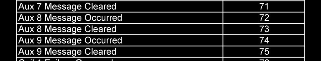
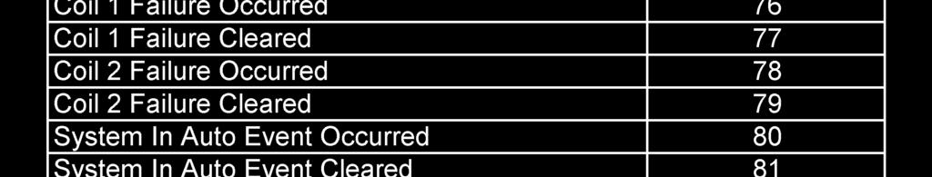
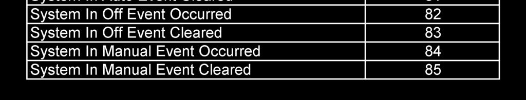
24 PART VIII: ALARM AND EVENT LOG MESSAGES The following lists all the possible messages that can be recorded within either the alarm or event logs. Battery1 Low Voltage Alarm Occurred/ Battery1 Disconnectd Alarm Occurred/ Battery1 Switch off Alarm Occurred/ Battery2 Low Voltage Alarm Occurred/ Battery2 Disconnectd Alarm Occurred/ Battery2 Switch off Alarm Occurred/ Charger 1 Fault Alarm Occurred/ Charger 2 Fault Alarm Occurred/ AC Power Failure Alarm Occurred/ Engine Overspeed Alarm Occurred/ Engine Failed to Start Alarm Occurred Start Engine Quit Alarm Occurred/ Low Oil Pressure Alarm Occurred/ High Water Temp Alarm Occurred/ Pressure Transducer Alarm Occurred/ Low Fuel Level Alarm Occurred/ Stop pushbutton Pressed in Engine Started / running Stopped Engine Lockout Sig Occurred Cleared Remote Start Sig Occurred Cleared System in Auto Mode Occurred System in Off Mode Occurred System in Manual Mode Occurred Auto Test Start Occurred Alarm Reset Button Occurred Battery1 voltage is/was less than the Battery Low Voltage trip voltage set in set point #306 Battery1 wiring has been disconnected and/or BAT1 switch is in the OFF position Battery1 wiring has been disconnected and/or BAT1 switch is in the OFF position Battery2 voltage is/was less than the Battery Low Voltage trip voltage set in set point #306 Battery2 wiring has been disconnected and/or BAT2 switch is in the OFF position Battery2 wiring has been disconnected and/or BAT2 switch is in the OFF position Charger 1 fault contacts are/were in a fault state. Causes could be disconnected battery, wrong battery voltage, AC power loss, etc. Charger 2 fault contacts are/were in a fault state. Causes could be disconnected battery, wrong battery voltage, AC power loss, etc. AC Power Failure declared when both battery chargers are in a fault condition at the same time. An overspeed signal was detected coming from the engine. FD4 controller must be put in OFF mode to reset this alarm. FD4 controller attempted to start engine in Auto mode but the engine failed to start (ie a engine run signal was never received). FD4 controller must be put in OFF mode to reset this alarm. FD4 controller lost the engine run signal from the engine while it was running in Auto mode. This could be a bad wire connection or a problem on the engine that shut the engine down other than an overspeed or failed to start condition. A low oil pressure signal was received from the engine while the engine was running for at least the amount of seconds set in setpoint #304. A high engine coolant water temperature signal was received from the engine while it was running. The pressure signal from the pressure transducer has fallen outside normal operating range potentially indicating a problem with the transducer or its wiring. A low fuel signal has been received for at least 3 seconds. An operator pressed the Stop pushbutton. Engine was started or stopped in either Auto or Manual mode. A remote engine lockout signal was received or cleared. A remote start signal was received or cleared. System was placed in Auto mode. System was placed in Off mode. System was placed in Manual mode. An automatic engine test sequence was started while in Auto mode by either the weekly program clock function or a user pressing the [TEST] button for 2 or more seconds A user did an alarm reset by pressing and holding the [SILENCE/RESET/ESC] button for 2 to 5 seconds. Page 24 of 32
25 Low Pressure Start Occurred Cleared Low Press Condition Occurred Cleared Deluge Start Occurred Cleared Controller Reboot Occurred Pressure Drop Occurred Cleared Low Intake Pressure Shutdown Occurred Shutdown Cleared Auxiliary Alarm Occurred Cleared A low pressure start was attempted because of a low pressure reading from the transducer or optional pressure switch while in Auto mode. System pressure dropped below the start pressure or the optional pressure switch indicates a low pressure condition. This can be logged in all modes of operation. A deluge start signal was received while in Auto mode. DC power was restored to the FD4 microprocessor. If setpoint #204 is set to yes, this event gets recorded when the system pressure drops below the setting in setpoint #205. If the low intake shutdown option is enabled in setpoint #116, a low suction signal will stop the engine. Indicates one of the aux alarms occurred as programmed in the user programs and was set to record in the event or alarm log but the text message assigned was 0. See Aux Alarm Text List Messages below for possible auxiliary alarm messages. Aux Alarm Text List Messages 0 Auxiliary Alarm 1 High Fuel Level 2 Fuel Spill 3 Fuel Tank Rupture 4 Low Pump Room Temp 5 Reservoir Low 6 Reservoir Empty 7 Reservoir High 8 Flow Meter On 9 Relief Valve Open 10 Low Suction Pressure 11 High Engine Oil Temp 12 Low Jacket Water Flw 13 Low Jacket Water Lvl 14 Low Hydraulic Press 15 Low Firewater Press 16 Air Damper Closed 17 Air Damper Open 18 Alternator Fault 19 Low Gear Oil Press 20 Low Coolant Level 21 High Gear Oil Temp 22 Start Motor Fault 23 Low Fuel Pressure 24 Pump On Demand 25 High Exhaust Temp 26 High Fuel Temp 27 Pump Room Ajar 28 ECM Alternate 29 ECM Failure 30 High System Pressure 31 Dump Valve 32 User Alarm Text List of possible internal variables used as inputs for aux alarm user programs. 30 Low Oil Pressure 31 General Battery Fault 32 Engine Quit Alarm 33 Pressure Transducer Fault 34 Low Intake Shutdown Alarm 35 Pump On Demand, Fire Condition 36 System Fault 37 Auto Mode 38 Manual Mode 39 Off Mode 40 Overspeed 41 Failed to Start 42 High Water Temp 43 AC Power Failure 44 Batt 1 Failure 45 Batt 2 Failure 46 Charger 1 Failure 47 Charger 2 Failure 48 General Charger Failure 49 Low Fuel Level 50 Pressure Drop Event 51 High System Pressure 52 Low Pressure 53 Engine Auto Available 54 Contactor Coil Failure 55 Test Mode 56 Hi Zone/Low Zone Mode 57 Contactor Coil 1 Failure 58 Contactor Coil 2 Failure 59 Engine running 60 Weekly Test Due 61 Dump Valve 62 Engine Lockout Latched Page 25 of 32
26 SD CARD FILE FORMAT. The controller is equipped with an SD (Secure Digital) memory card on the motherboard to store the Pressure log, Event log, Operators Manual in PDF format, Auxiliary Alarm configuration information and the controller drawings in PDF format. The SD card is located on the right hand edge of the motherboard and is removed by pressing in on the right edge of the card to release from the card holder. When the SD card is removed, data is still being recorded on temporary flash memory on the motherboard. Once the card is replaced, the stored data will be written back to the SD Card. When the SD card is removed, the LCD display will indicate that the card is missing and that is should be replaced. If the card is not replaced within approximately 1 minute, the alarm will sound and the System Fault LED will come on. Once the SD card is replaced, the System Fault LED will go out but the Alarm Silence button must be pressed to silence the alarm horn. The data stored on the SD card is in standard ASCII text format and can be read by an computer equipped with an appropriate SD card reader. These are readily available at any electronics store. The data on the SD card is in the following format: PressXXX.txt file Data is stored in a standard comma delimited file as follows: 07/27/07, 11:07:52, 060 Date Time Pressure Each file starting with Press contains one days worth of pressure data. Events.txt file Data is stored in a standard comma delimited file as follows: 07/27/07,11:09:26,Battery2 Low Voltage,,060 cont Date Time Event Action Pressure 1, 0, 0, 0, 1, 1, 1, cont Auto mode, Engine running, Charger 1 Fault, Charger 2 fault, Battery 1 OK, Battery 2 OK, ACPwerFail cont 1, 000 LowFuelLvl Event Txt Page 26 of 32


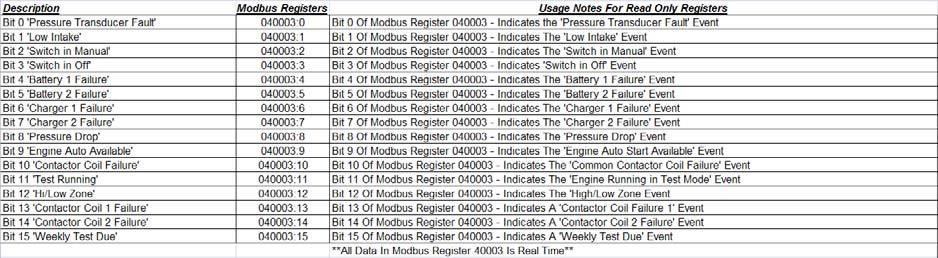
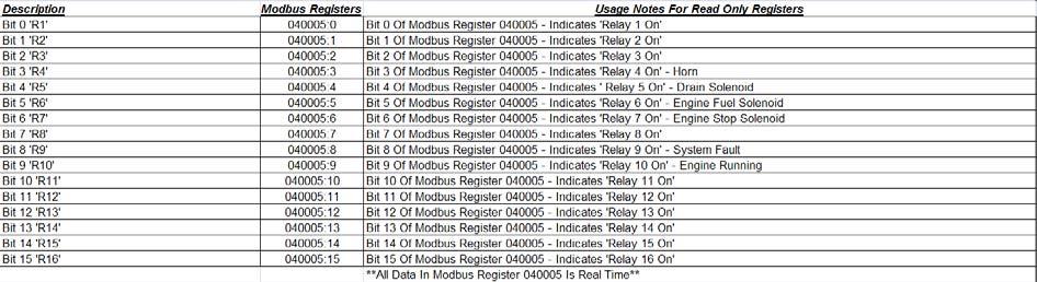
27 Appendix A RS485 Port Usage For Serial Modbus RTU protocol: The Modbus option on the fire pump controller boards can be enabled by disabling the printer option to the onboard RS485 port. All communications to this port will be in a 2 wire RS485 format. 255 controllers can communicate on a single network. The pinout cabling required for connection to the port is as follows. It is necessary to apply a terminating resistor to both ends of the network. Note-Only 50 Modbus registers can be polled at time from the controller. I/O servers must be set up accordingly. Modbus Setup From Controller Interface: From the 200 series user preference configuration screens the Modbus setting can be access from screens 220 through 223. Screen 220 is used to set the Modbus address All Modbus devices on a network must have a unique address. Screen 221 is used to enable/disable the Modbus option. If Yes is selected the Modbus will be enabled and the RS485 port can no longer be used as a printer port. Screen 222 is used to set the baud rate for the RS485 port. The baud rates possible are 2400, 4800, 9600, 19200, and bits/second. Note that the baud rate setting is for the RS485 port in general and applies for Modbus and printer usage. Screen 223 is used to set the Modbus parity. Valid selections are Even, Odd, and None. This setting must match the parity setting of all other Modbus devices on the network. Modbus Register Usage Description: The historical event and pressure logs, and real time clock can be accessed and controlled through the Modbus registers listed below. Register is a write to controller only register where commands can be entered to accomplish the following as seen in figure 1.1. Depending on the Modbus I/O server used, either the individual bits in register can be toggled or integer values can be written. Either way, the controller automatically zeros register after a valid command is received. Figure 1.1 Real Time Event Monitoring: All events listed below in figure 1.2 are real time and can be viewed in Modbus register Figure 1.2 depicts the 16 bit breakdown and cross reference. This is not to be confused with the historical event log. Page 27 of 32


28 Figure 1.2 Page 28 of 32

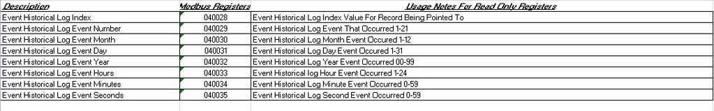
29 Setting And Reading The Real Time Clock Through Modbus: Modbus registers through are real time clock read registers as seen in figure 1.3. To set the clock current values must be entered into registers through Any of these registers left to zero will result in an incorrect clock setting. Once desired clock date and time values are entered bit 0 of register must be toggled for the controller to accept the values. This can be done by setting bit 0 high or writing a 1 to register The controller will then accept the new values. Most Current And Historical Alarms and Events: Figure 1.3 The most recent event or alarm date time stamped can be viewed from Modbus registers through Register contains a number representing the most current alarm or event and if it is an occurring or clearing event. The meaning of this number can be cross referenced from figures 1.6 through 1.9. Date and time for the event or alarm are viewed in registers through See figure 1.4 for register interpretation. Figure 1.4 The historical events and alarms can be viewed from Modbus registers through Here it is possible to scroll through the entire log and set the log pointer to the most current record. Register contains a number representing the actual log number entry location in the controller. Register contains a number representing the event or alarm that can be indexed using figures 1.6 through 1.9. Registers through show the date and time stamp information for the log record being pointed to. To maneuver through the log: Toggling bit 3 or writing an 8 to register will increment the log by one entry. Toggling bit 4 or writing a 16 to register will decrement the log by one entry. Toggling bit 7 or writing a 128 to register will set the log to view the most current log entry. It is recommended to set the log to the most current entry before scrolling. Upon doing this the historical log should show the same data from registers in Figure 1.4. When scrolling, it is possible to move forward and backward through roughly a full weeks worth of data. Page 29 of 32


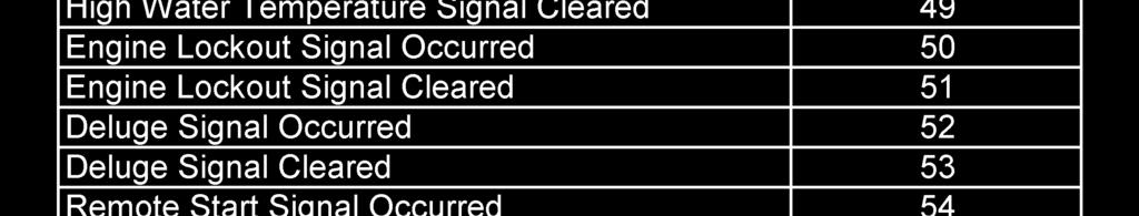

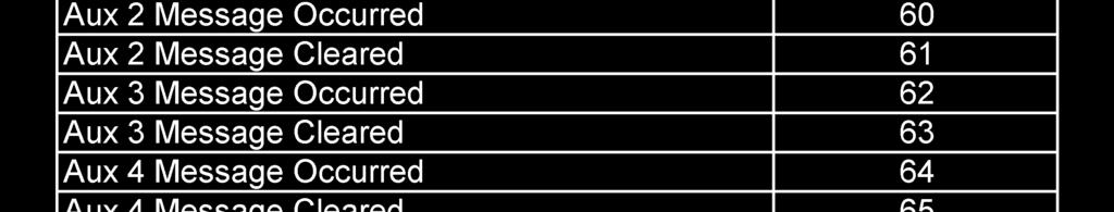

30 Figure 1.5 Figure 1.6 Figure 1.7 Page 30 of 32


31 Figure 1.8 Figure 1.9 Most Current And Historical Pressure Readings: The most recent system pressure with date time stamp can be viewed from Modbus registers through Register contains a number representing the most current pressure read by the controller. The value is scaled and should match the pressure displayed on the main status screen on the controller OID. Date and time stamp for the pressure reading is viewed in registers through See figure 1.10 for register interpretation. The pressure log must be set up to log on an interval for these pressure readings to be logged. Figure 1.10 The historical pressure readings can be viewed from Modbus registers through Here it is possible to scroll through the entire log and set the log pointer to the most current record. Register contains a number representing the actual log number entry location in the controller. Register contains a number representing the logged pressure reading. Registers through show the date and time stamp information for the log record being pointed to. To maneuver through the log: Toggling bit 5 or writing a 32 to register will increment the log by one entry. Page 31 of 32
DIESEL Engine Fire Pump Controllers Features
 1-1 Printer / Recorder The industrial grade thermal printer is housed in a rugged steel enclosure within the controller. The on/off switch, feed and reset buttons are front accessible. A bi-color status
MANUAL ELECTRIC FIRE PUMP CONTROLLERS METRON SERIES M450
 MANUAL ELECTRIC FIRE PUMP CONTROLLERS METRON SERIES M450 TABLE OF CONTENTS PART I GENERAL DESCRIPTION... PAGE 2 PART II FUNCTIONS... PAGE 2 PART III INSTALLATION... PAGE 3 PART IV INITIAL INSTALLATION
Energy Division
 Energy Division http://energy.tycoelectronics.com Installation and Operating Manual GEN-TRANS Automatic Generator Transfer Switch Controller with Metering Tyco Electronics UK Limited Crompton Instruments
REVISION HISTORY REVISION HISTORY
 FILTER CONTROLLER REVISION HISTORY Filter Flush Controller forms part of the Netafim range of filtration controllers all designed to make filteration more reliable and economical.. Contact any of the Netafim
MODEL 520 REMOTE START ENGINE MANAGEMENT SYSTEM
 MODEL 520 REMOTE START ENGINE MANAGEMENT SYSTEM DSE 520 ISSUE 4 4/4/02 MR 1 TABLE OF CONTENTS Section Page INTRODUCTION... 4 CLARIFICATION OF NOTATION USED WITHIN THIS PUBLICATION.... 4 1. OPERATION...
5220 AUTOMATIC MAINS FAILURE MODULE OPERATING MANUAL
 5220 AUTOMATIC MAINS FAILURE MODULE OPERATING MANUAL > Section DSE Model 5220 Automatic Mains Failure & Instrumentation System Operators Manual TABLE OF CONTENTS
OPERATING MANUAL Digital Diesel Control Remote control panel for WhisperPower generator sets
 Art. nr. 40200261 OPERATING MANUAL Digital Diesel Control Remote control panel for WhisperPower generator sets WHISPERPOWER BV Kelvinlaan 82 9207 JB Drachten Netherlands Tel.: +31-512-571550 Fax.: +31-512-571599
Operator s Series 300 Generator Paralleling System
 Operator s Series 300 Manual Generator Paralleling System +Before reading please note the following: DANGER is used in this manual to warn of a hazardous situation which, if not avoided, will result in
Fire Water Utility 2002 Training Manual Raw Water Storage Area
 Effective: 10/21/11 Page 1 of 17 Rev. by J. Shively Fire Water Utility 2002 Training Manual Raw Water Storage Area Document Revision Change Table Revision Number Revision Description Revised By Revision
DKG-109 AUTOMATIC MAINS FAILURE UNIT
 Tel: +90-216-466 84 60 Fax: +90-216 364 65 65 datakom@datakom.com.tr http://www.datakom.com.tr DKG-109 AUTOMATIC MAINS FAILURE UNIT FEATURES Automatic mains failure Engine control Generator protection
4.2 Component Identification
 Digital Control Panels Deep Sea Electronics 5220 4.1 General 4.2 Component Identification 4.3 The YML5220 Controller 4.4 Description of Controls 4.5 Navigation 4.5.1 General Navigation 4.5.2 The Event
MANUAL ELECTRIC FIRE PUMP CONTROLLERS METRON SERIES MV600
 MANUAL ELECTRIC FIRE PUMP CONTROLLERS METRON SERIES MV600 TABLE OF CONTENTS PART I GENERAL DESCRIPTION... PAGE 2 PART II FUNCTIONS... PAGE 2 PART III INSTALLATION... PAGE 3 PART IV INITIAL INSTALLATION
CURTIS TOLEDO. AF Series Compressors VS models with VFD WARNING
 AUGUST, 2004 REV.A CURTIS TOLEDO OPERATOR S MANUAL SUPPLEMENT AF Series Compressors VS models with VFD WARNING Personal injury and/or equipment damage will result by failing to pay attention to the vital
HGM7100N SERIES (HGM7110N/7120N) GENSET CONTROLLER USER MANUAL
 GENSET CONTROLLER USER MANUAL") HGM7100N SERIES (HGM7110N/7120N) GENSET CONTROLLER USER MANUAL SMARTGEN (ZHENGZHOU) TECHNOLOGY CO., LTD. Chinese trademark English trademark SmartGen make your generator smart SmartGen Technology Co.,
HGM7100N SERIES (HGM7110N/7120N) GENSET CONTROLLER USER MANUAL SMARTGEN (ZHENGZHOU) TECHNOLOGY CO., LTD. Chinese trademark English trademark SmartGen make your generator smart SmartGen Technology Co.,
ACSI MODEL 1406BB-04-AO POWER SUPPLY INSTALLATION INSTRUCTIONS
 II 1400-10 ACSI MODEL 1406BB-04-AO POWER SUPPLY INSTALLATION INSTRUCTIONS Features: Up to 1.95 Amps Load Capacity Class 2 Rated Outputs Overload, Over Voltage, and Short Circuit Protection Standby Battery
Flight Systems. Replacement for KASSEC DESCRIPTION
 DESCRIPTION The is a universal generator controller that will start, stop, and provide engine protection for most generators. Universal replacement for both the 90353 and 90354 KASSEC Compatible with most
Automatic Genset Controller, AGC-4 Display readings Push-button functions Alarm handling Log list
 OPERATOR'S MANUAL Automatic Genset Controller, AGC-4 Display readings Push-button functions handling Log list DEIF A/S Frisenborgvej 33 DK-7800 Skive Tel.: +45 9614 9614 Fax: +45 9614 9615 info@deif.com
USER MANUAL ZHENGZHOU SMARTGEN TECHNOLOGY CO.,LTD
 HGM400 Series Genset Controller (HGM410/HGM420) USER MANUAL ZHENGZHOU SMARTGEN TECHNOLOGY CO.,LTD CONTENTS 1 OVERVIEW... 5 2 PERFORMANCE AND CHARACTERISTICS... 6 3 SPECIFICATION... 8 4 OPERATION... 9 4.1
Deep Sea Electronics Plc
 Deep Sea Electronics Plc 550 Operators Manual Author Miles Revell Deep Sea Electronics Plc Highfield House Hunmanby Industrial Estate North Yorkshire YO14 0PH ENGLAND Tel +44 (0) 1723 890099 Fax +44 (0)
DKG-109J AUTOMATIC MAINS FAILURE UNIT
 DKG-109J AUTOMATIC MAINS FAILURE UNIT CANBUS VERSION FEATURES True RMS measurements Automatic mains failure ECU control and monitoring through J1939 CAN J1939 ECU warnings displayed as text Various engine
Deep Sea Electronics Plc
 Deep Sea Electronics Plc 5120 AUTOMATIC MAINS FAILURE MODULE OPERATING MANUAL Author: Anthony Manton Deep Sea Electronics Plc Highfield House Hunmanby North Yorkshire YO14 0PH England Tel: +44 (0) 1723
HGM1780. Automatic Genset Controller USER MANUAL. Smartgen Technology
 HGM1780 Automatic Genset Controller USER MANUAL Smartgen Technology Smartgen Technology Co., Ltd No. 28 Jinsuo Road Zhengzhou Henan Province P. R. China Tel: 0086-371-67988888/67981888 0086-371-67991553/67992951
Advantage-D. Operating Instructions and Maintenance Manual. Central Vacuum Systems (Expandable/Modular Models) (Ver.
 (Ver.") Advantage-D Series 3 Central Vacuum Systems (Expandable/Modular Models) (Ver. 8/05) Operating Instructions and Maintenance Manual DESCRIPTION The Becker Advantage-D and Advantage-L central vacuum systems
Advantage-D Series 3 Central Vacuum Systems (Expandable/Modular Models) (Ver. 8/05) Operating Instructions and Maintenance Manual DESCRIPTION The Becker Advantage-D and Advantage-L central vacuum systems
HGM6320T AUTOMATIC GENERATOR CONTROLLER USER MANUAL
 HGM6320T AUTOMATIC GENERATOR CONTROLLER USER MANUAL Smartgen Technology CONTENT 1 SUMMARY... 4 2 PERFORMANCE AND CHARACTERISTICS... 4 3 SPECIFICATION... 5 4 OPERATION... 6 4.1 LCD DISPLAY... 6 4.2 KEY
MATRIX LLC LEVEL CONTROL PANEL
 MATRIX LLC LEVEL CONTROL PANEL Installation Operation Maintenance Manual 1-26-09 REV-0.3 1 INDEX Introduction. 3 Product Configurations..... 4 I/O Descriptions. 8 Operation o Intercooler, Accumulator,
HSC940 Genset Controller CONTENTS 1 OVERVIEW PERFORMANCE AND CHARACTERISTICS SPECIFICATION OPERATION KEY FUNCTIONS...
 CONTENTS 1 OVERVIEW... 4 2 PERFORMANCE AND CHARACTERISTICS... 5 3 SPECIFICATION... 7 4 OPERATION... 8 4.1 KEY FUNCTIONS... 8 4.2 INDICATOR LIGHT... 9 4.3 AUTO START/STOP OPERATION... 10 4.4 MANUAL START/STOP
VC-4820 Programmable DC-DC Converter with Battery Charger function USER'S MANUAL
 1. INTRODUCTION VC-4820 Programmable DC-DC Converter with Battery Charger function USER'S MANUAL This MCU controlled Step Down DC-DC Converter has a digitally adjustable output in 0.2V increments. This
Installation and Maintenance Instructions. World Leader in Modular Torque Limiters. PTM-4 Load Monitor
 World Leader in Modular Torque Limiters Installation and Maintenance Instructions PTM-4 Load Monitor 1304 Twin Oaks Street Wichita Falls, Texas 76302 (940) 723-7800 Fax: (940) 723-7888 E-mail: sales@brunelcorp.com
Operations Manual. Automated Fuel Maintenance System FUEL TECHNOLOGIES INTERNATIONAL
 Operations Manual Automated Fuel Maintenance System FTI-10A & 20A FUEL TECHNOLOGIES INTERNATIONAL Replacement Manuals Available on Website: www.fueltechnologiesinternational.com 07/15/2015 Rev E Fuel Technologies
R & D SPECIALTIES ROTROL I USER'S MANUAL
 R & D SPECIALTIES ROTROL I USER'S MANUAL TABLE OF CONTENTS INTRODUCTION...2 SPECIFICATIONS...2 CONTROLS AND INDICATORS...3 TIME DELAYS...4 INSTALLATION...5 SYSTEM OPERATION...9 TROUBLESHOOTING...13 OPTIONAL
Product Manual. Part Number: MVP-193 Mefi-6 ECU Revision: 1.0
 Product Manual Part Number: MVP-193 Mefi-6 ECU Revision: 1.0 Copyright Controls, Inc. P.O. Box 368 Sharon Center, OH 44274 Phone 330.239.4345 Fax 330.239.2845 www.controlsinc.com TABLE OF CONTENTS PRIOR
DKG-509 AUTOMATIC MAINS FAILURE UNIT
 DKG-509 AUTOMATIC MAINS FAILURE UNIT CANBUS AND MPU VERSIONS DESCRIPTION The controller is a comprehensive AMF unit for single genset standby or dual genset mutual standby operations. The unit is available
Cascade CD101 Auto-Start Controller. Installation and Operations Manual Sections 40 & 75
 Cascade CD101 Auto-Start Controller Installation and Operations Manual 00-02-0594 2018-02-15 Sections 40 & 75 In order to consistently bring you the highest quality, full featured products, we reserve
The committee proposes the attached Public Input for further review at Second Draft.
 National Fire Protection Association Report of 61 http://submittals.nfpa.org/terraviewweb/contentfetcher?commentpara... 1/5/2017 1:55 PM Committee Input No. 60-NFPA 20-2016 [ Global Input ] The committee
DEEP SEA ELECTRONICS PLC
 COMPLEX SOLUTIONS MADE SIMPLE. DEEP SEA ELECTRONICS PLC DSE5220 AUTO MAINS FAILURE MODULE OPERATING MANUAL Deep Sea Electronics Plc Highfield House Hunmanby North Yorkshire YO14 0PH ENGLAND Sales Tel:
DEEP SEA ELECTRONICS PLC
 DEEP SEA ELECTRONICS PLC 703 AUTOMATIC START MODULE OPERATING INSTRUCTIONS Author:- John Ruddock 703 Operating Instructions Issue Beta1 25/08/2003 2:45 PM JR - 1 - >
Installation. Part A, Section 3. This section covers the following unit configurations. 3400V 3500V. Voltage 4. Pump Piston (E, F, G)
") Part A, Section 3 Model This section covers the following unit configurations. Voltage 4 300V 3400V 3500V Pump Piston (E, F, G) Manifold Control 4-Port (A) 6-Port (B or C) -Port (S or T) Vista Pattern
Part A, Section 3 Model This section covers the following unit configurations. Voltage 4 300V 3400V 3500V Pump Piston (E, F, G) Manifold Control 4-Port (A) 6-Port (B or C) -Port (S or T) Vista Pattern
Application Engineering
 Application Engineering February, 2009 Copeland Digital Compressor Controller Introduction The Digital Compressor Controller is the electronics interface between the Copeland Scroll Digital Compressor
Te 803 Electronic Controller. Service, Operation & Technical Information Manual
 Te 803 Electronic Controller Service, Operation & Technical Information Manual WARNING! Technical descriptions and data given in this document are accurate, to the best of our knowledge, but can be subject
TG350 User Manual. Manual Revision: Min. FW Revision: Date Released: 09/01/ DYNAGEN Technologies Inc
 TG350 User Manual Manual Revision: 1.4.0 Min. FW Revision: 1.42.01 Date Released: 09/01/2014 Table of Contents 1 Introduction 1.1 Specifications... 3 2 Installation 2.1 Terminal s... 6 2.2 Typical Wiring...
PowerView PV380-R2 Mechanical Configuration
 PowerView PV380-R2 Mechanical Configuration Operations Manual *Products covered in this document comply with European Council electromagnetic compatibility directive 2004/108/EC and electrical safety directive
OPERATING INSTRUCTIONS ECON-M
 OPERATING INSTRUCTIONS ECON-M INDEX 1.0 Introduction 2.0 Salient features, Protection & Supervision 3.0 Display/ Front Panel 4.0 Switches Description 5.0 LED Annunciations Description 6.0 Lamp Test 7.0
MB A 12V/24V DC PROGRAMMABLE DUAL BATTERY ISOLATOR
 MB-3688 120A 12V/24V DC PROGRAMMABLE DUAL BATTERY ISOLATOR User Manual Warning and Precautions MB-3688 is built with corrosion resistant material and the main electronic assembly is well sealed inside
CONTENTS ESC CONTENTS... 1 FEATURES... 2 LAYOUT... 3 DISPLAYS... 4 CONNECTIONS... 5 MENU... 6 MESSAGES... 7 SYSTEM OPERATION... 8
 CONTENTS ESC CONTENTS... 1 FEATURES... 2 LAYOUT... 3 DISPLAYS... 4 CONNECTIONS... 5 MENU... 6 MESSAGES... 7 SYSTEM OPERATION... 8 1 F EATURES s Engine Status Center (ESC - p/n 105536) provides the pump
32XR. 3 Phase Duplex Pump Control Panel (Level Transmitter Based) Quick Start Guide
 Quick Start Guide") 32XR 3 Phase Duplex Pump Control Panel (Level Transmitter Based) Quick Start Guide RED ALARM LIGHT LEVEL CONTROLLER H-O-A SWITCHES HORN SILENCE INNER DOOR MOTOR STARTERS WITH INTERCHANGEABLE OVERLOAD MODULES
32XR 3 Phase Duplex Pump Control Panel (Level Transmitter Based) Quick Start Guide RED ALARM LIGHT LEVEL CONTROLLER H-O-A SWITCHES HORN SILENCE INNER DOOR MOTOR STARTERS WITH INTERCHANGEABLE OVERLOAD MODULES
GENSET CONTROL MODULE LEVEL 0 A120A. User selectable time delays for engine start and engine stop (cool down).
.") Technical Data Sheet GENSET CONTROL MODULE LEVEL 0 A120A Features: One model for both spark ignition and diesel engines. 4-alarm light outputs with automatic lamp-test provision. Overspeed adjustment not
Technical Data Sheet GENSET CONTROL MODULE LEVEL 0 A120A Features: One model for both spark ignition and diesel engines. 4-alarm light outputs with automatic lamp-test provision. Overspeed adjustment not
Digital Diesel Control Remote control panel for GENVERTER GV4 and GV7i
 OPERATING MANUAL Digital Diesel Control Remote control panel for GENVERTER GV4 and GV7i Art. nr. 40200801 WHISPER POWER BV ENGLISH: PAGE 1 Kelvinlaan 82 9207 JB Drachten NEDERLANDS: PAGINA 41 Netherlands
GENSET CONTROL MODULE A121H / A241H. User selectable time delays for engine start and engine stop (cool down).
.") Technical Data Sheet GENSET CONTROL MODULE A121H / A241H Features: Models for both 12V and 24V systems. One model for both spark ignition and diesel engines. 4-alarm light outputs with lamp-test provisions.
Technical Data Sheet GENSET CONTROL MODULE A121H / A241H Features: Models for both 12V and 24V systems. One model for both spark ignition and diesel engines. 4-alarm light outputs with lamp-test provisions.
HAT700 Series HAT700/HAT700I/HAT700B/HAT700BI/HAT700S ATS CONTROLLER USER MANUAL
 HAT700 Series HAT700/HAT700I/HAT700B/HAT700BI/HAT700S ATS CONTROLLER USER MANUAL ZHENGZHOU SMARTGEN TECHNOLOGY CO.,LTD Software Version Version Date Note 1.0 2014-09-09 Original release. 1.1 2015-03-04
DEEP SEA ELECTRONICS PLC
 COMPLEX SOLUTIONS MADE SIMPLE DEEP SEA ELECTRONICS PLC DSE704 AUTOSTART CONTROL MODULE OPERATING MANUAL 057-042 704 Operating Instructions Issue 2.1 18/06/2007 11:27:00 JR - 1 - Deep Sea Electronics Plc
HGM6410/6420. Automatic Generator Module. With J1939 Interface OPERATING MANUAL. Smartgen Electronics
 HGM6410/6420 Automatic Generator Module With J1939 Interface OPERATING MANUAL Smartgen Electronics Smartgen Electronic Equipment Co,.Ltd No.12 Dongqing Street Zhengzhou Henan Province P.R.China Tel : (0086)-371-67992951
HGM1780 AUTOMATIC GENERATOR MODULE CONTENT 1. SUMMARY PERFORMANCE AND CHARACTERISTICS SPECIFICATION OPERATION...
 CONTENT 1. SUMMARY...4 2. PERFORMANCE AND CHARACTERISTICS...4 3. SPECIFICATION...5 4. OPERATION...6 4.1. DISPLAY PANEL...6 4.2. LCD ICON INSTRUCTION...7 4.3. DISPLAY INSTRUCTIONS...7 4.4. DISPLAY DESCRIPTION...8
GENSET CONTROL MODULE A121A / A241A
 Technical Data Sheet GENSET CONTROL MODULE A121A / A241A Features: Models for both 12V and 24V systems. One model for both spark ignition and diesel engines. 4-alarm light outputs with lamp-test provisions.
HGM6410/6420 AUTOMATIC GENERATOR MODULE WITH J1939 INTERFACE SOFTWARE MANUAL
 HGM6410/6420 AUTOMATIC GENERATOR MODULE WITH J1939 INTERFACE SOFTWARE MANUAL SMARTGEN ELECTRONICS Smartgen Electronic Equipment Co., Ltd No.12 Dongqing Street Zhengzhou Henan Province P.R.China Tel : (0086)-371-67992951
ECU-02 Ver2.1 Automatic Engine Control Unit Operators Manual
 ECU-02 Ver2.1 Automatic Engine Control Unit Operators Manual Headquarters : No.3, Lane 201, Chien Fu St., Chyan Jenn Dist., Kaohsiung, TAIWAN Tel : + 886-7-8121771 Fax : + 886-7-8121775 URL : http://www.kutai.com.tw
HGM6310D/6320D AUTOMATIC GENERATOR MODULE USER MANUAL
 HGM6310D/6320D AUTOMATIC GENERATOR MODULE USER MANUAL SMARTGEN ELECTRONIC CONTENT 1 SUMMARY... 4 2 PERFORMANCE AND CHARACTERISTICS... 4 3 SPECIFICATION... 6 4 OPERATION... 7 4.1 KEY FUNCTION... 7 4.2 AUTOMATIC
ITCEMS950 Idle Timer Controller - Engine Monitor Shutdown Isuzu NPR 6.0L Gasoline Engine
 Introduction An ISO 9001:2008 Registered Company ITCEMS950 Idle Timer Controller - Engine Monitor Shutdown 2014-2016 Isuzu NPR 6.0L Gasoline Engine Contact InterMotive for additional vehicle applications
HGM1770 Automatic Generator Control Module OPERATING MANUAL Smartgen Electronic
 HGM1770 Automatic Generator Control Module OPERATING MANUAL Smartgen Electronic CONTENT 1. SUMMARY... 4 2. PERFORMANCE AND CHARACTERISTICS... 4 3. SPECIFICATIONS... 5 4. OPERATION... 6 5. PROTECTION...
AUTOMATIC STAND-BY AND PEAK-LOAD CONTROL
 KUHSE Operating Instructions Control Unit for Gen. Power Sets AUTOMATIC STAND-BY AND PEAK-LOAD CONTROL Type: KEA 071-SPL TA71SXXE.01 July 1996 (REPLACES 1994 EDITION) GENERAL DESCRIPTION AND APPLICATION
HP21 SERVICE SUPPLEMENT UNIT INFORMATION. TSC6 Two-Speed Control
 SERVICE UNIT INFORMATION SUPPLEMENT HP21 Corp. 9426 L10 Litho U.S.A. All HP21-4 and -5 units (single and three phase) are equipped with a TSC6 two-speed control. The TSC6 (A14) two-speed control contains
Be2K-Plus AMF panel control wiring --
 Be2K-Plus OEM's Manual V200 - August - 014 page 1 Be2K-Plus AMF panel control wiring -- Consult Section 17.0 for software upgrades & revisions The information in this document may be subject to change
HGM72 Automatic Generator Module OPERATING MANUAL Smartgen Electronic
 HGM72 Automatic Generator Module OPERATING MANUAL Smartgen Electronic CONTENT 1 SUMMARY... 4 2 FEATURES... 4 3 SPECIFICATION... 4 4 DISPLAY SYMBOL AND OPERATION... 5 5 ALARM... 7 6 PARAMETERS TABLE (ONLY
TE2010-GE Instructions manual
 TE2010-GE Instructions manual Hardware: 3.1-4.0 Software: 3.7 PREFACE Thanking you for preference, TECNOELETTRA SRL hopes that the use of this equipment could be a reason of satisfaction. This manual is
AUTOSTART 705S V1.00 AUTOSTART 710S / 720S / 730S V1.04 Programming Reference and Check Sheets
 The Generator Controls Division of Frank W. Murphy AUTOSTART 705S V1.00 AUTOSTART 710S / 720S / 730S V1.04 Programming Reference and Check Sheets MODEX AUTOMATION FRANK W. MURPHY LTD. Church Road Laverstock
Generator Start Control Module
 Generator Start Control Module Part# GSCM Rev C. Code Version: 5.13 ATKINSON ELECTRONICS, INC. 14 West Vine Street Murray, Utah 84107 Table of Contents Operations... 3 Specifications... 3 GSCM Wiring Diagram...
HGM6320T AUTOMATIC GENERATOR CONTROLLER USER MANUAL
 HGM6320T AUTOMATIC GENERATOR CONTROLLER USER MANUAL Smartgen Technology Smartgen Technology Co., Ltd No. 28 Jinsuo Road Zhengzhou Henan Province P. R. China Tel: 0086-371-67988888/67981888 0086-371-67991553/67992951/67992952
MD10. Engine Controller. Installation and User Manual for the MD10 Engine Controller. Full Version
 MD10 Engine Controller Installation and User Manual for the MD10 Engine Controller. Full Version File: MartinMD10rev1.4.doc May 16, 2002 2 READ MANUAL BEFORE INSTALLING UNIT Receipt of shipment and warranty
Application Engineering
 Application Engineering March 2011 Copeland Digital Compressor Controller Introduction The Digital Compressor Controller is the electronics interface between the Copeland Scroll Digital compressor or the
ANALOG CONTROL PANEL
 ANALOG CONTROL PANEL 1. AC VOLTS: Displays generator output in voltage. 2. AC FREQUENCY: Displays the speed of the generator set in Hertz. 3. Percent of Load: Displays percentage of load on the generator.
Installation Instructions & Users Manual
 Installation Instructions & Users Manual UTILITY/ BUILDING INPUT 120 VAC ( OPTION) 15-20A N L CONTROL BOARD G SECURITY LIGHTING POWER SUPPLY (OPTION) CHARGER- POWER SUPPLY ASSBY XFMR (OPTION) CBM MODEL
Idle Timer Controller - ITC Freightliner MT45 Contact InterMotive for additional vehicle applications
 An ISO 9001:2008 Registered Company System Operation Idle Timer Controller - ITC805 2013-2018 Freightliner MT45 Contact InterMotive for additional vehicle applications The ITC805 system shuts down idling
DEEP SEA ELECTRONICS PLC
 COMPLEX SOLUTIONS MADE SIMPLE. DEEP SEA ELECTRONICS PLC DSE4120 AUTO MAINS FAILURE MODULE OPERATING MANUAL Deep Sea Electronics Plc Highfield House Hunmanby North Yorkshire YO14 0PH ENGLAND Sales Tel:
HGM6400 Automatic Genset Controller (With J1939 Interface) USER MANUAL Smartgen Technology
 USER MANUAL Smartgen Technology") HGM6400 Automatic Genset Controller (With J1939 Interface) USER MANUAL Smartgen Technology Chinese trademark English trademark Smartgen make your generator smart Smartgen Technology Co., Ltd No. 28 Jinsuo
HGM6400 Automatic Genset Controller (With J1939 Interface) USER MANUAL Smartgen Technology Chinese trademark English trademark Smartgen make your generator smart Smartgen Technology Co., Ltd No. 28 Jinsuo
DEEP SEA ELECTRONICS PLC
 COMPLEX SOLUTIONS MADE SIMPLE. DEEP SEA ELECTRONICS PLC DSE710 AUTOSTART CONTROL MODULE OPERATING MANUAL Deep Sea Electronics Plc Highfield House Hunmanby North Yorkshire YO14 0PH ENGLAND Sales Tel: +44
AE R2 December CoreSense Diagnostics v2.11 for Copeland Discus Compressors AE R2. Table of Contents
 AE8-1368 R2 December 2012 CoreSense Diagnostics v2.11 for Copeland Discus Compressors Table of Contents 1.0 Overview 1.1 Functionality 1.1.1 Diagnostics 1.1.2 Communication 1.1.3 Fault History 1.2 Features
METRON ELEDYNE OPERATING INSTRUCTIONS FOR DIESEL ENGINE CONTROLLER TYPE EFP/EN12845-ES 12 & 24 VOLT VERSION
 OPERATING INSTRUCTIONS FOR DIESEL ENGINE CONTROLLER TYPE EFP/EN12845-ES 12 & 24 VOLT VERSION Revision 1, June 2008 18 Autumn Park, Dysart Road, Grantham, LINCS. NG31 7DD. United Kingdom Telephone: +44
Supersedes CL2 (512) Form CL2 (615) STARTUP CHECKLIST PHONE: CUSTOMER ORDER NO: JCI TEL NO: JCI ORDER NO: JCI CONTRACT NO:
 Form CL2 (615) STARTUP CHECKLIST PHONE: CUSTOMER ORDER NO: JCI TEL NO: JCI ORDER NO: JCI CONTRACT NO:") YMC 2 - MOD A STARTUP CHECKLIST Supersedes 160.78-CL2 (512) Form 160.78-CL2 (615) STARTUP CHECKLIST CUSTOMER: JOB NAME: ADDRESS: LOCATION: PHONE: CUSTOMER ORDER NO: JCI TEL NO: JCI ORDER NO: JCI CONTRACT
YMC 2 - MOD A STARTUP CHECKLIST Supersedes 160.78-CL2 (512) Form 160.78-CL2 (615) STARTUP CHECKLIST CUSTOMER: JOB NAME: ADDRESS: LOCATION: PHONE: CUSTOMER ORDER NO: JCI TEL NO: JCI ORDER NO: JCI CONTRACT
Product Guide: Series III Pump Control Board Set (RoHS)
") revised 04/08/10 Description: The Series III Pump Control Board Set provides motor drive and pump control for a wide assortment of pumps from Scientific Systems, Inc. The assembly consists of two circuit
revised 04/08/10 Description: The Series III Pump Control Board Set provides motor drive and pump control for a wide assortment of pumps from Scientific Systems, Inc. The assembly consists of two circuit
DEEP SEA ELECTRONICS PLC
 COMPLEX SOLUTIONS MADE SIMPLE DEEP SEA ELECTRONICS PLC DSE720 AUTOSTART CONTROL MODULE OPERATING MANUAL http://bestgenerator.spb.ru/?page_id=6765 Deep Sea Electronics Plc Highfield House Hunmanby North
B U L L E T I N. Application Engineering. AE June Intelligent Store Discus 2.0
 June 2008 Intelligent Store Discus 2.0 Table of Contents 1.0 Overview of Intelligent Store Discus 2.0 4.9 Crankcase Heater Control 1.1 Functionality 4.10 Anti Short Cycle 1.1.1 Diagnostics 4.11 MCC Value
Power Flame Incorporated
 Power Flame Incorporated DC-4 SEQUENCE OVERFIRE DRAFT CONTROL SYSTEM OPERATING AND MAINTENANCE MANUAL THE POWER TO MANAGE ENERGY 2001 South 21 st Street, Parsons, Kansas 67357 Telephone 620-421-0480, Fax
Vission 20/20 micro-controller. Operation and service manual
 Vission 20/20 micro-controller Operation and service manual Section Title Table of Contents Section Number How To Use This Manual...TOC-8 Section 1 Operational Flow Charts Requirements to Start Compressor...1-1
Be-K3 OEM s Manual --
 Be-K3 OEM's Manual V200 - July - 010 page 1 Be-K3 OEM s Manual -- Consult Section 17.0 for software upgrades & revisions The information in this document may be subject to change without notice. No part
P445 Series Electronic Lube Oil Control
 FANs 125, 121 s Section P Product/Technical Bulletin P445 Issue Date 0100 P445 Series Electronic Lube Oil The P445 Series Electronic Lube Oil is designed for use on refrigeration compressors equipped with
GENSET CONTROL MODULE LEVEL 1 A121CM / A241CM. Special logic to re-establish cranking following a false start.
 Technical Data Sheet GENSET CONTROL MODULE LEVEL 1 A121CM / A241CM Features: Models for both 12V and 24V systems. One model for both spark ignition and diesel engines. 5-alarm light outputs with lamp-test
INSTALLATION AND MAINTENANCE MANUAL FOR DIESEL ENGINE FIRE PUMP CONTROLLERS MODEL GPD
 INSTALLATION AND MAINTENANCE MANUAL FOR DIESEL ENGINE FIRE PUMP CONTROLLERS MODEL GPD 1 Table of Contents 1. Introduction 2. Installation 3. Main Features 4. Home 5. Alarms 6. Configuration 7. History
CORESENSE DIAGNOSTICS FOR STREAM REFRIGERATION COMPRESSORS
 Date of last update: Apr-15 Ref: D7.8.4/0112-0415/E Application Engineering Europe CORESENSE DIAGNOSTICS FOR STREAM REFRIGERATION COMPRESSORS CoreSense Diagnostics for Stream Refrigeration Compressors...
INSTRUCTIONS FOR INSTALLING AND OPERATING THE UNIVERSAL AUTOSYNC MODEL ASPSS DUAL COMPRESSOR SEQUENCER CONSOLE S/N 1638 AND ABOVE
 COMPRESSOR 1 EMERGENCY SHUTDOWN OFF POWER ON COMP LOADED COM PRESSOR OPERATING HOURS SYSTEM PRESSURE COMPRESSOR 2 EMERGENCY SHUTDOWN OFF POWER ON COMP LOADED COM PRESSOR OPERATING HOURS LEAD/LAG CONTROL
Installation. Part A, Section 3. This section covers the following unit configurations. Voltage 1, 2, 3. Vista Standard (V) A3EN-04-[3V-A-AAXV]-11
![Installation. Part A, Section 3. This section covers the following unit configurations. Voltage 1, 2, 3. Vista Standard (V) A3EN-04-[3V-A-AAXV]-11](/thumbs/87/95082297.jpg "Installation. Part A, Section 3. This section covers the following unit configurations. Voltage 1, 2, 3. Vista Standard (V) A3EN-04-[3V-A-AAXV]-11") Part A, Section 3 This section covers the following unit configurations. Model All Voltage 1, 2, 3 Pump All Manifold All Control Vista Standard (V) A 3-0 A 3-1 Section A 3 WARNING: Allow only qualified
Part A, Section 3 This section covers the following unit configurations. Model All Voltage 1, 2, 3 Pump All Manifold All Control Vista Standard (V) A 3-0 A 3-1 Section A 3 WARNING: Allow only qualified
INSTALLATION AND MAINTENANCE MANUAL FOR DIESEL ENGINE FIRE PUMP CONTROLLERS AUTOMATIC CONTROLLER
 INSTALLATION AND MAINTENANCE MANUAL FOR DIESEL ENGINE FIRE PUMP CONTROLLERS AUTOMATIC CONTROLLER MODEL GPD 1 Table of Contents 1. Introduction 2. Installation 3. Main Features 4. Home 5. Alarms 6. Configuration
GTFM V. Operation / Installation Manual. Gas Turbine Flow Monitor. Computer Weld Technology, Inc. Manual Part Number: A8M5026 Revised: 09/11/2013
 Computer Weld Technology, Inc. 10702 Old Bammel N Houston Rd. Houston, TX 77086 Phone: (713) 462-2118 Fax: (713) 462-2503 Email: cwt@cweldtech.com GTFM V Gas Turbine Flow Monitor Operation / Installation
GCU-10. Automatic Engine Control Unit Operators Manual
 GCU-10 Automatic Engine Control Unit Operators Manual KUTAI ELECTRONICS INDUSTRY CO., LTD. TEL : +886-7-8121771 FAX : +886-7-8121775 Website : www.kutai.com.tw Headquarters : No.3, Lane 201, Chien Fu St.,
ICL Three Pump Controller
 ICL Three Pump Controller Pump Operation The number of pumps that the program controls can be selected by enabling only the ones that are currently installed and in service. The enable/disable setting
AT EVO SERIES BATTERY CHARGER
 STANDARD FEATURES 5 YEAR WARRANTY EVO AT Series Battery Charger is HindlePower s next generation SCR-based utility battery charger. This evolutionary product is revolutionary in its design and operation
Battery Management Innovation. For 12-volt automotive starting batteries and starting/charging systems INSTRUCTION MANUAL
 Battery Management Innovation For 12-volt automotive starting batteries and starting/charging systems INSTRUCTION MANUAL ! CAUTION Because of the possibility of personal injury, always use extreme caution
Axpert-CSS AMTECH DRIVES Axpert-CSS Amtech
 The Axpert-CSS is a range of Combination Soft Starter panels offered by AMTECH DRIVES. We also offer the module unit as an individual product, named as Axpert-Opti torque Soft Starter. This is only the
GSC400 Series. Automatic Gen-Set Controller Manual. Revision 2.6
 GSC400 Series Automatic Gen-Set Controller Manual Revision 2.6 GSC400 Automatic Gen-Set Controller Installation and User Manual MAN-0076 Rev2.6, GSC400 User Manual.doc, May 2010 2 of 105 Thank You For
On-Premise Pro Instruction Manual
 On-Premise Pro Instruction Manual 0901133 Rev: A (11/13) Page 1 of 20 TABLE OF CONTENTS Introduction... 4 Features... 4 Pre-installation... 5 Installation... 5 Operating Modes... 6 Programming... 7 Load
Paralleling Equipment
 Paralleling Equipment PowerCommand Model 300 Digital Master Control Description The PowerCommand TM Digital MasterControl is a microprocessor-based paralleling system component, designed to directly interface