INSTRUCTIONS. 4-Link Parallel With Panhard Bar Rear Suspension Systems FOR MOPAR MUSCLE CARS: B-BODY (RS-5460)
|
|
|
- Lindsey Daniels
- 6 years ago
- Views:
Transcription

 Revised:")
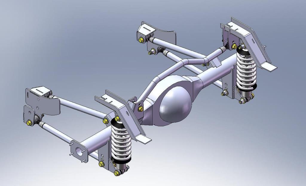
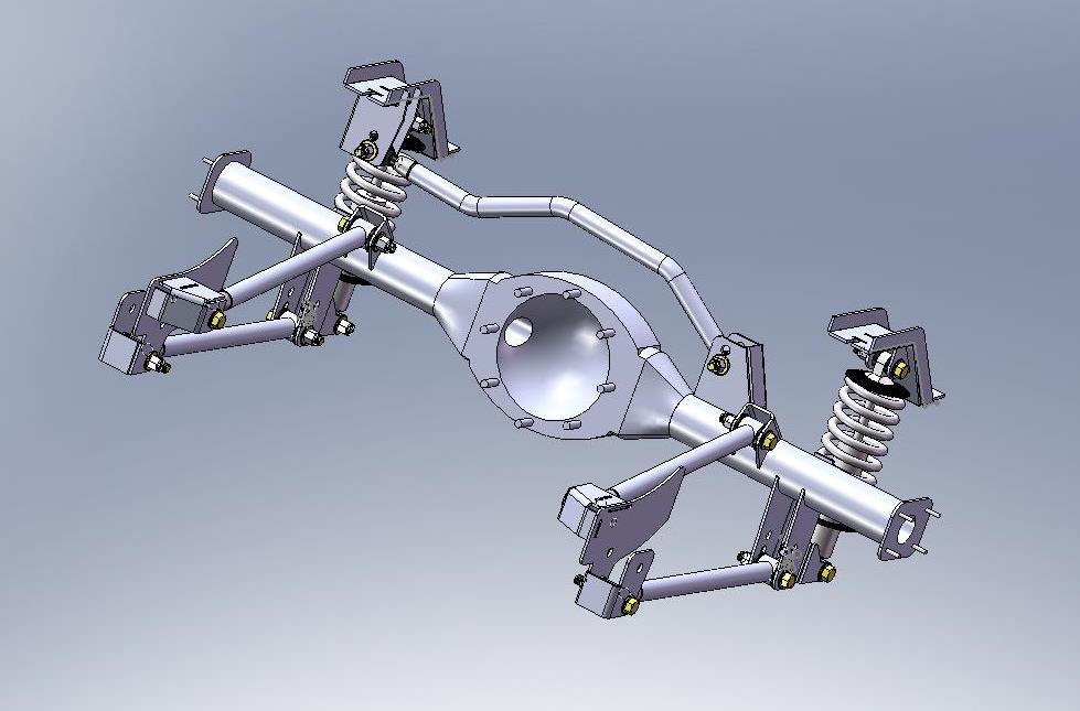
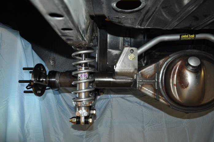
1 MOPAR B-BODY 4-LINK SYSTEM W/PANHARD BAR INSTRUCTIONS 4-Link Parallel With Panhard Bar Rear Suspension Systems FOR MOPAR MUSCLE CARS: B-BODY (RS-5460) Revised:
2 Page 2
3 Page 3
4 Page 4
5 Page 5
6 Installation Instructions Parallel 4-Link Panhard Bar Rear Suspension System Part # RS Mopar B-Body Vehicles System Contents Forward Trailing Link Brackets (1 Left and 1 Right) Lower Rear Trailing Arm Differential Brackets (2) Upper Rear Trailing Arm Differential Mount (2) Lower Trailing Arm Set w/adjustable Rod Ends Lower Trailing Arm Mounting Hardware Kit Upper Trailing Arm Set w/adjustable Rod Ends Upper Trailing Arm Mounting Hardware Kit Upper Coil Over Mount Brackets Upper Coil Over Mount Brackets Template Lower Coil Over Mount Brackets With Hardware (2) Coil Over Shocks w/ Springs (2 Each) Coil Over Mounting Hardware Kit Panhard Bar with Brackets & Adjustable Rod Ends (2) Four each of 1-1/4 and 1-5/8 diameter spacers Thank you for purchasing this Parallel 4-Link Rear Suspension System for Mopar B-Body Vehicles. This system is manufactured by Control Freak Suspensions in Winter Springs, Florida. We believe this system is the best available at any price. As with most aftermarket performance suspension products, the end user is solely responsible for determining the suitability of any and all such products, regardless of manufacturer. Because this system, and others like it, are typically subjected to uses that could exceed its mechanical limits, there is no warranty, expressed or implied. Blue Moon Services LLC d/b/a Control Freak Suspensions cannot control how this product is installed or used. By purchasing this product you are assuming all risks associated with its installation and use and agree to having appropriate skills for its installation and use. Blue Moon Services LLC d/b/a Control Freak Suspensions, our vendors and suppliers will not be held responsible, liable or accountable for any injury, damage, loss, penalties or fines that occur, directly or indirectly, from the installation and use of this product. Please note that this system includes components that must be welded accurately into place. While installation is relatively easy for those with appropriate skills and experience, novices, or those who question their abilities, should employ a professional for installation. Fit is guaranteed on vehicles that are unmolested that is cars that have not suffered any chassis or unitized body damage. Such damage can bend or alter the unitized chassis, making installation more difficult and may require chassis adjustment and/or straightening by professionals before installation. Page 6
7 Read all of the instructions before starting installation. IMPORTANT NOTES: 1. All brackets in this kit must be welded into place. 2. Be certain to remove carpeting, insulation or other flammables from the area being welded or subjected to welding heat. 3. Installation of this rear suspension system is straightforward, but ease of installation is based upon your level of experience and ability. 4. By following these instructions, measuring properly, cutting and drilling accurately, we strongly recommend that all welded parts get tack welded into place prior to final welding. This allows you to fit the entire system before final welding is done. 5. Some parts of this system may have been accurately threaded by our CNC machine shop to receive the supplied adjustable rod and/or bushing ends. Be careful not to cross thread the rod ends into these machined parts. Use anti-seize compound on all threaded parts. We are not responsible for any cross threaded parts. 6. All rod ends that are threaded into tubes must use the supplied jam nuts for safety. 7. Use extra caution in jacking and stabilizing the vehicle for this installation. The differential will need to be removed and reinstalled, so we strongly recommend the use of a professional lift to make the job easier and safer. 8. An assistant is recommended during parts of this installation. What Else Do I Need? Everything you need is included in the purchase price. Installation requires welding. Disconnect your battery BEFORE welding. If you don t, you run the risk of ruining electronic ignition and entertainment components in the car.. IMPORTANT NOTES: Unpacking the System Your rear suspension system arrives boxed and unassembled. Since this system requires all brackets to be welded into place we are unable to pre-assemble the product. While some parts may arrive assembled, please note that the assembled parts may not be appropriately installed or tightened for actual use. You are responsible for making certain all fasteners are installed correctly and appropriately tightened. If you ordered brakes with your system, the brake kit is boxed separately and has its own set of instructions provided by brake manufacturer. Page 7

8 Carefully open all boxes and remove all components. Lay out all of the components and familiarize yourself with them using the CAD drawings on page 2 as your guide. This will make installation quicker and easier. Read through the entire instruction book and familiarize yourself with the steps before beginning installation. Once you have read through the instructions and identified all of the parts, prepare your tools for installation. You are now ready to begin installation. Preparing for Installation 1. Measure the ride height of the vehicle by taking measurements from the rocker panel to the ground. Take a front and rear measurement on each side and note it in a notebook. We recommend using masking tape at all four measuring points and writing the measurement so it can always be seen. This is your baseline stock ride height. 2. Support the differential with jacks. If you are using a lift, support with tall jacks. With the differential safely supported, remove the sway bar and the end brackets holding it in place against the frame. 3. Remove any exhaust components that may interfere with removing the rear differential. 4. Disconnect the driveshaft from the differential. 5. Remove the shocks from both sides of the differential. 6. Making certain the differential is supported by jacks, with a helper remove the front and rear leaf spring bolts, keeping the differential from turning while doing so. You will remove the entire differential assembly. 7. Once the differential has been removed, take this opportunity to clean it up. After the upper and lower trailing arm brackets have been welded into place, and the original spring perches removed (if you choose to do so), you can paint the rear before reinstalling with the new suspension system. 8. You will need to cut off the stock shock mounts on the rear pans, just above the differential. Do this carefully and grind down any sharp edges, as shown in the picture to the right. 9. Examine the rails on the car. Over the years, the vehicle may have been incorrectly jacked up in some areas which can slightly mushroom or otherwise move the rails slightly out of line. This is an opportunity to straighten or adjust the rails prior to putting the rear suspension brackets in place. 10. Prior to installing the brackets, the area around each bracket must be sanded to raw metal and cleaned. We use an air die grinder with a 3 RoLok sanding disc 80 Page 8


9 grit works fine. Clean at least 1/2 beyond the bracket, leaving ample clean metal for a good weld. Installation of the Rear Suspension Brackets The picture above shows the forward frame bracket on the outside of the rail, firmly against the sheet metal lip. Do this on both sides then measure each brackets distance from a fixed point on each side of the chassis. Make fine adjustments to ensure they are positioned at equal distances and square. 1. Place the forward frame brackets into place. There is a right and left bracket. Correct placement is shown from the outside and inside of the rail in the photos above. Make certain the area around the perimeter is cleaned to bare metal allowing a good welding surface. The forward edge of the brackets should be perpendicular to the chassis. 2. You will now need to prepare the upper coil over mounts on the frame rail in the wheel house arch. This next step does require you to use the provided template and cut out a portion of the rail. The cut out portion will be replaced with a special bracket that will not only reinforce the chassis, making it stronger than it was, but also provides the upper coil over mounting point. Remove the rubber Page 9


10 snubbers and save two of the screws. They are used to locate part of the upper coil over mount. 3. Place the template on the rear portion of the wheel arch as shown in the photos. Carefully outline the template with a marker on both sides of the rail and connect your outline on the underside of the rail. Once completed, use masking tape to make your outline stand out and making it easier to cut out the material. The picture to the right shows this. 4. Carefully cut out the material so you end up with a cutout as shown in the picture below. We use a 3 cutoff wheel to make the cuts, but regardless of what tools you use, please use a face shield and gloves to protect yourself from flying debris. 5. Once you have made the cutout on both sides of the car, clean the area around the cutout down to metal. You will be welding to this area so the surface needs to be clean as show in the picture to the left. 6. On the forward part of the cutout you will need to make two slits and bend the metal up as shown in the picture to the left. This is so the new reinforcing plate will overlap smoothly into position. Page 10
 side of the vehicle as shown in the photo below on the left.")

11 7. There are two (2) upper coil over mounts. These are 2 wide Z-shaped plates with tabs welded to them. One has an additional large bracket that hangs down. The bracket that also contains the large hanging bracket goes on the right (passenger) side of the vehicle as shown in the photo below on the left. The one with just the tabs goes on the left (driver) side of the vehicle as shown in the picture below on the right. Slip the rear part of the plate inside the open chassis rail as shown. Place the rest of the bracket into position so it follows your cut and is flush to the upper part of the cutout. Hold the upper part in position with the small sheet metal screw used to hold the rubber snubber into position as shown below. Tack weld into position. 8. Place the Z-shaped side plates into position on the inside and outside of the chassis rail as shown. Clamp to hold the plates into position and tack weld into once they are properly aligned. Repeat this on the other side of the vehicle as shown below. 9. Attach the upper and lower trailing arms to the forward frame brackets. You will use two of the 1-5/8 machined spacers on either side of the lower trailing arm bushings to fill the gap. Hand tighten the bolts. 10. Attach the rear lower trailing arm brackets to the lower trailing arms. Only hand tighten the bolts. Attach the upper trailing arm to the smaller upper trailing arm brackets. Hand tighten the bolts. This provides ease for the initial tack weld position for the upper and lower trailing arm brackets on the differential. 11. Move the differential into position making certain that it is centered between the rails and at the ride height you have chosen. Now adjust the height of the rear axle to your desired ride height, which is typically between the upper and lower shock mounts. Ride height is entirely up to you and the look / stance you want the car to have. BUT you also must consider undercar clearance and tire size. 12. At this time, you should set a rough pinion angle before locating the upper & lower mounts. If you can get to it, hold an angle finder on the crank pulley and note the angle. If you can t get into the crank pulley area with an angle finder, use the angle of the transmission tailshaft. Now place the angle finder on the front of the rear axle pinion and rotate the axle to duplicate the same angle. Placing the differential on two Page 11

12 (2) jack stands and using a floor jack to adjust the angle is the simplest way to make even fine adjustments. Set the pinion angle from zero degrees to minus one-half degree in accordance to the driveline angle. The picture below is the equivalent of zero degrees: 13. Once you have the pinion angle set and the differential properly centered side-toside, place the brackets that are attached to the lower trailing arms onto the differential. When you are satisfied that the brackets are in the appropriate location and perpendicular to the differential axle tubes and the ground, place a tack weld in the corners of the brackets just to hold them into position. If you need to make an adjustment later you will only have to cut through a few tack welds. 14. Place the upper trailing arm differential brackets into position on the top front of the differential tubes. You can see the approximate position by viewing the CAD drawing on page 3. Just like on the lower brackets, tack the upper brackets into position ensuring they are parallel with the lower trailing arms and perpendicular to the differential axle tubes. Place a few tack welds into the corners of the brackets. 15. Now is the time to attach the panhard bar to the bracket on the right side of the chassis and the other bracket which will rest on the differential axle tube on the left side. Before placing a tack weld on the differential bracket for the panhard bar, be certain that the bar is running in line with the differential tubes. Once it is straight, tack weld the differential bracket for the panhard bar. Page 12

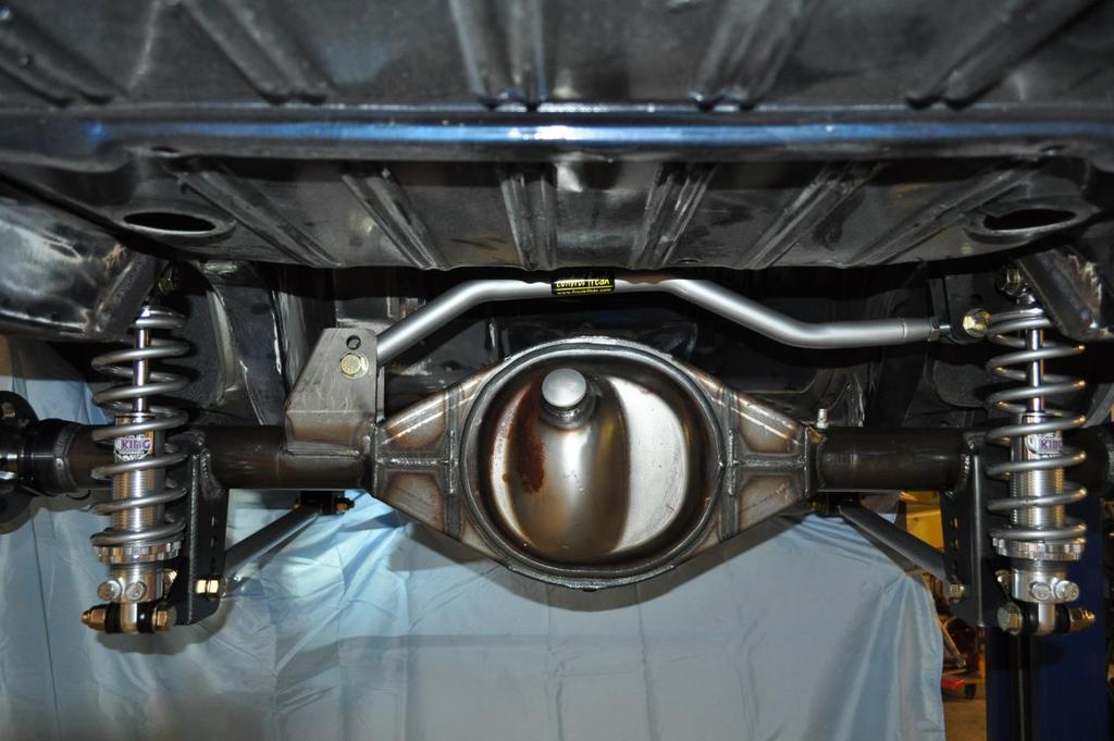
13 16. Attach the lower coil over mount into the holes on the lower trailing arm brackets on the differential tubes. The lower you locate the bracket, the lower the car will sit. The higher you locate the bracket, the higher the car will sit. Snug the nuts but do not torque them. Make certain that the upper coil over mount is directly perpendicular to the lower mounting bracket. You can make side to side adjustments with the lower coil over mount using the slotted holes for alignment. 17. If adjustments need to be made, now is the time to do it before permanently welding all of the brackets into their final position. After checking all of the tack welds, and being sure that everything is evenly and correctly installed, you can remove the trailing arms. 18. Carefully remove the trailing arms and the panhard bar. With the aid of a helper, carefully remove the differential from under the vehicle and prepare it for final welding of the brackets. 19. Before welding brackets to the differential, loosen the axles so heat does not build up and melt the axle seals. Weld a little at a time and alternate from side to side. We prefer to turn the differential upside down, making it easier to get a good, clean weld. 20. Weld all of the tack welded brackets and parts under the vehicle into place. 21. When welding the upper coil over mount brackets, be certain to weld in the open hole on the bottom of the bracket as shown in the picture below. NOTE: Before final welding of the under-vehicle parts, remove carpeting and anything flammable from the interior of the vehicle. 22. Once welded and cooled, take the opportunity to prime and paint the welded brackets and the areas around the welds. Page 13
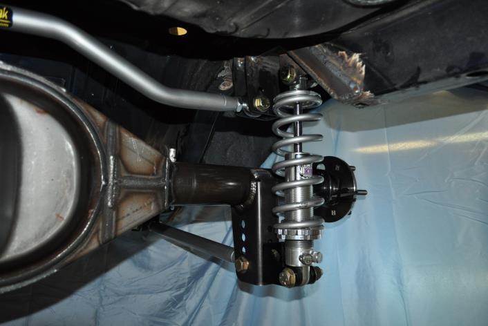
14 23. You can now reinstall the differential, trailing arms and panhard bar, making certain to tighten all bolts. 24. Prepare the coil over shocks for assembly. Paint some silver anti-seize compound onto the bottom half of the threads on the coil over body. This will ensure than when the coil over is assembled and under load that the nut will still turn without galling. Thread the lower jam nut followed by the primary spring seat onto the body, install the spring and attach the hat to hold the spring. 25. Install the coil over shocks. On the lower coil over mount, use two of the 1-1/4 machined spacers on either side of the coil over bushing to fill the gap. We recommend adjusting the coil over shocks about two full turns of threads after the spring is hand tightened. This is a good starting point. Coil overs will settle up to ¾ after about fifteen miles of driving, so set the height of your vehicle about ¾ higher than you want it. It will settle. 26. You can now put the vehicle on the ground. 27. That s it. You are done. Drive carefully. We strongly recommend that all fasteners are re-torqued at between miles of driving. Page 14
15 IMPORTANT DISCLAIMER In an effort to offer our customers the value and service, Blue Moon Services LLC d/b/a Control Freak Suspensions (herein referred to as Control Freak) reserves the right to change suppliers, specifications, colors, prices, materials. Each of the previous items is subject to change without notice. Control Freak is not responsible for any typographical errors or misinterpretations. Quantities are limited on some items. WARRANTY DISCLAIMER The purchaser understands and recognizes that racing parts, specialized high performance equipment, and all parts and services sold by Control Freak, are exposed to many and varied conditions due to the manner in which they are installed and used. Control Freak makes no warranties, either express or implied, including any warranty of merchantability or fitness for a particular purpose other than those contained in its current catalog with respect to the goods identified on the face of the invoice. There is no warranty expressed or implied as to whether the goods sold hereby will protect purchaser or ultimate user of such goods from injury or death. Control Freak assumes no liability after this period. DAMAGE CLAIMS Always inspect your package upon delivery. Inspect all packages in the presence of the delivery driver. The driver must note any damage. Ask the driver the Carrier s procedures for handling damage claims. You must hold the original box, packing material and damaged merchandise for inspection or the carrier will not honor the claim. Notify Control Freak for instructions on returning damaged goods. Control Freak is not responsible if no notification is given within two (2) days of receipt. SHORTAGES Always check the contents of your delivery to insure all the parts that you ordered were received. Please read the invoice. Double check all packing materials, small items may be wrapped inside with these products. Shortages may occur from damage to the box, so save all packing materials. Inspect the box for holes that would allow parts to fall out. If you are missing any item(s) be sure to check your invoice for back orders or canceled items before calling the customer service department. If Control Freak has to split a shipment into multiple boxes, packages may be delivered on different days. You need to contact the customer service department within 5 days of delivery to assure the prompt replacement. Control Freak assumes no liability after this period. REFUSALS All refused COD customers will be billed a 15% restocking charge plus freight to and from the destination! If you have questions please contact Control Freak. WARRANTY CLAIMS If an item has a manufacturer s warranty as being free from defects we will exchange that item. If the item has been used and you are requesting warranty work, this may take up to 30 days as warranty work is done in-house by Control Freak. If you have any questions please contact customer service. RETURNS Control Freak wants you to be satisfied with your purchase. If within 30 days after you receive your shipment you are not satisfied, you may return the item for refund or exchange. All exchanged or returned merchandise must be in original factory condition with no modifications or alterations. Returned merchandise must include all packaging materials, warranty cards, manuals, and accessories. If the items being returned need to be repackaged there will be a re-packing charge. Re-pack the item in a sturdy box and include a copy of your invoice and complete the form on the back of the invoice. You must ship orders back PRE-PAID. WE DO NOT ACCEPT COD SHIPMENTS. All exchanges need to have reshipping charges included. Items that are returned after 30 days are subject to 15% restocking charges. Absolutely no returns on custom built suspension systems or other special order merchandise. **Some items may not be street legal in some countries. Such items may be legal for racing vehicles only which may never be used upon a highway Page 15
16 MOPAR B-BODY 4-LINK SYSTEM W/PANHARD BAR Control Freak Suspensions 1101 Oak Lane, Suite 1031 Winter Springs, Florida Toll Free: (888) Direct: (407) Fax: (407) Page 16
INSTRUCTIONS. 4-Link Triangulated Rear Suspension System FOR MOPAR MUSCLE CARS: B-BODY (RS-5530) B-BODY (RS-5540)
 B-BODY (RS-5540)") MOPAR 1966-1972 B-BODY 4-LINK TRIANGULATED SYSTEM INSTRUCTIONS 4-Link Triangulated Rear Suspension System FOR MOPAR MUSCLE CARS: 1966-1970 B-BODY (RS-5530) 1971-1972 B-BODY (RS-5540) Revised: 7-1-2015
MOPAR 1966-1972 B-BODY 4-LINK TRIANGULATED SYSTEM INSTRUCTIONS 4-Link Triangulated Rear Suspension System FOR MOPAR MUSCLE CARS: 1966-1970 B-BODY (RS-5530) 1971-1972 B-BODY (RS-5540) Revised: 7-1-2015
INSTRUCTIONS. 4-Link Parallel With Adjustable Panhard Bar Rear Suspension System FOR MOPAR MUSCLE CARS: A-BODY (RS-5435)
") MOPAR A-BODY 4-LINK PARALLEL COIL OVER SYSTEM INSTRUCTIONS 4-Link Parallel With Adjustable Panhard Bar Rear Suspension System FOR MOPAR MUSCLE CARS: 1967-1976 A-BODY (RS-5435) Revised: 6-1-2011 Page 2
MOPAR A-BODY 4-LINK PARALLEL COIL OVER SYSTEM INSTRUCTIONS 4-Link Parallel With Adjustable Panhard Bar Rear Suspension System FOR MOPAR MUSCLE CARS: 1967-1976 A-BODY (RS-5435) Revised: 6-1-2011 Page 2
Front Axle Assembly: Hairpin Radius Rods
 INSTRUCTIONS 916-395 *916-395* August 2011, Speedway Motors, Inc. Front Axle Assembly: Hairpin Radius Rods This radius rod front end kit is used with OEM or aftermarket tube or I-beam axles that use a
INSTRUCTIONS. Triangulated 4-Link Coil Over Rear Suspension System (RS-2450) For FORD Muscle Cars: FAIRLANE
 For FORD Muscle Cars: FAIRLANE") FORD 1962-65 FAIRLANE 4-LINK TRIANGULATED SYSTEM INSTRUCTIONS Triangulated 4-Link Coil Over Rear Suspension System (RS-2450) For FORD Muscle Cars: 1962-1965 FAIRLANE Revised: 10-1-2011 1962-1965 Fairlane
FORD 1962-65 FAIRLANE 4-LINK TRIANGULATED SYSTEM INSTRUCTIONS Triangulated 4-Link Coil Over Rear Suspension System (RS-2450) For FORD Muscle Cars: 1962-1965 FAIRLANE Revised: 10-1-2011 1962-1965 Fairlane
INSTRUCTIONS. Triangulated 4-Link Coil Over Rear Suspension System. For FORD / MERCURY Muscle Cars: MUSTANG COUGAR
 FORD Tech Line: 888-325-6462 MUSTANG / COUGAR 4-LINK TRIANGULATED SYSTEM INSTRUCTIONS Triangulated 4-Link Coil Over Rear Suspension System For FORD / MERCURY Muscle Cars: 1965-1970 MUSTANG 1967-1969 COUGAR
INSTRUCTIONS
 INSTRUCTIONS 910-34489 SOCALOOK RADIUS ROD BRACKET ASSEMBLY One side only/repeat for opposite side. Figure 1 STEP 1. LOCATING RADIUS ROD BRACKETS From under the vehicle, remove the 2 bolts that secure
INSTRUCTIONS FOR AMC MUSCLE CARS: AMX JAVELIN AMX / JAVELIN ADJUSTABLE REAR SWAY BAR. Tech Line:
 AMC Tech Line: 888-325-6462 1968-74 AMX / JAVELIN ADJUSTABLE REAR SWAY BAR INSTRUCTIONS FOR AMC MUSCLE CARS: 1968-1970 AMX 1968-74 JAVELIN Requires Control Freak Rear Suspension Systems RS-1400T, RS-1400P
CAREFULLY READ THESE GUIDELINES BEFORE STARTING!
 INSTRUCTIONS 910-73060 *910-73060* Street Stock Roll Cage Kit Installation Guidelines CAREFULLY READ THESE GUIDELINES BEFORE STARTING! These are the basic guidelines for the installation of a roll cage
Wilwood Brake Kit for Total Performance Spindle
 INSTRUCTIONS 835-140170 Speedway Motors, Inc. May 2011 Wilwood Brake Kit for Total Performance Spindle Note: NOTE: Disc brakes operate in a harsh environment. To prevent bolts from working loose, every
Installation and Tuning Instructions for TM Multi Carb linkage kit PLEASE READ INSTRUCTIONS COMPLETELY BEFORE BEGINNING INSTALLATION
 INSTRUCTIONS Installation and Tuning Instructions for TM Multi Carb linkage kit 135-6721 135-6723 Speedway Motors, Inc. September 2009 PLEASE READ INSTRUCTIONS COMPLETELY BEFORE BEGINNING INSTALLATION
INSTRUCTIONS 12 Circuit Wiring Kit Instructions
 Fan 47 9 56 4 7 6 72 40 45 48 5 8 6 Gauge Power Temp Sender Headlight Power Power Radio Constant Power Instruments and Dash Rear of Vehicle Ignition and Lights Fuse Panel & Front of Vehicle Horn Alt Excitor
INSTRUCTIONS TUBULAR CONTROL ARMS & COIL-OVER CONVERSION FOR AMC MUSCLE CARS: 1970 AMX JAVELIN SPIRIT, HORNET, GREMLIN, CONCORD
 AMC TUBULAR CONTROL ARMS & COIL OVER KIT INSTRUCTIONS TUBULAR CONTROL ARMS & COIL-OVER CONVERSION FOR AMC MUSCLE CARS: 1970 AMX 1970-74 JAVELIN SPIRIT, HORNET, GREMLIN, CONCORD Revised 6/1/2012 www.freakride.com
INSTRUCTIONS TUBULAR CONTROL ARMS & COIL-OVER CONVERSION FOR FORD MUSCLE CARS: FORD FAIRLANE CO-2330 Small Block CO-2335 Big Block
 FORD 1962-65 FAIRLANE CONTROL ARMS & COIL OVER SYSTEM INSTRUCTIONS TUBULAR CONTROL ARMS & COIL-OVER CONVERSION FOR FORD MUSCLE CARS: 1963-1965 FORD FAIRLANE CO-2330 Small Block CO-2335 Big Block Revised:
Please Read Instructions Completely Before Starting Your Installation QTY. PART NO. DESCRIPTION
 INSTRUCTIONS 916-31926 Master Cylinder and Pedal Assembly Speedway Motors, Inc. 2015 Master Cylinder and Pedal Assembly Model T Model A, and '32 Fords The master cylinder is suitable for 4-wheel disc or
INSTRUCTIONS ASSEMBLY INSTRUCTIONS - FOLLOW STEP BY STEP
 INSTRUCTIONS 910-28905 916-28901 March 2011, Speedway Motors, Inc. Adapts '49-'53 Ford/Mercury Flatheads to Late Model, Ford C4 or AOD Automatic Transmissions FORD C4 TRANSMISSION IDENTIFICATION GUIDE
INSTRUCTIONS Circuit Wiring Kit Instructions _2017. Fuse Box Connections. (viewed from underside) 2018, Speedway Motors, Inc.
 2018, Speedway Motors, Inc.") Fuse Box Connections (viewed from underside) 4D 4C 100 50 300 4D 4C 4B 4A 43 107 39 103 3B 2G 104 93 2F 2E 2D 2C 2B 40 69A 102 101 105 2G 2F 2E 3A A 2A B 40A,B 27 69A 106 201, Speedway Motors, Inc. 1 Fuse
Fuse Box Connections (viewed from underside) 4D 4C 100 50 300 4D 4C 4B 4A 43 107 39 103 3B 2G 104 93 2F 2E 2D 2C 2B 40 69A 102 101 105 2G 2F 2E 3A A 2A B 40A,B 27 69A 106 201, Speedway Motors, Inc. 1 Fuse
40A A 40B. Horn Relay Connector. Brake Switch. Third Brake Light. Brake Switch. Brake Switch. Wires. page 3. Rear Body Feed Wires.
 Fuse Box Connections (viewed from underside) 4D 4C 4D 0 50 300 4C 43 7 39 3 6 4 93 A 2G 2F 2E 2D 2C 2B 2G 2F 2E 40 69A 2 1 5 27 69A 3A B 40A,B 11A,B 40A 156 Dimmer Dome Feed page 2 Horn Relay 2D 2 29 40B
5) The trailing arm should then pivot smoothly on the chassis. 6) Install the rear bolt. 7) Place one drop of blue Loctite
 The trailing arm should then pivot smoothly on the chassis. 6) Install the rear bolt. 7) Place one drop of blue Loctite") INSTALLATION INSTRUCTIONS 1301 / 1302 / 1305 / 1306 THANK YOU FOR CHOOSING HOTCHKIS PERFORMANCE PRODUCTS Removal of Stock Lower Trailing Arms 1) Place car on level surface. 2) Support rear of the car on
INSTALLATION INSTRUCTIONS 1301 / 1302 / 1305 / 1306 THANK YOU FOR CHOOSING HOTCHKIS PERFORMANCE PRODUCTS Removal of Stock Lower Trailing Arms 1) Place car on level surface. 2) Support rear of the car on
2236 Sway Bar Installation Instructions
 2236 Sway Bar Installation Instructions Thank you for your purchase of this Hotchkis Performance product. Your stabilizer bar set was designed with the performance and durability you ve come to expect
USE THE PARTS LIST BELOW TO MAKE SURE YOUR KIT IS COMPLETE BEFORE INSTALLATION. IF ANY PIECES ARE MISSING, PLEASE CONTACT:
 60-65 Ford Falcon Triangulated 4-Link Suspension Installation Instructions Tech Line: 1-855-693-1259 www.totalcostinvolved.com Read and understand these instructions before starting any work! USE THE PARTS
2253 FRONT AND REAR SPORT SWAY BAR SET CHEVROLET B-BODY
 2253 FRONT AND REAR SPORT SWAY BAR SET 65-66 CHEVROLET B-BODY Thank you for your purchase from our line of classic Chevrolet B-body suspension parts. Please call us at (877) 4NO-ROLL if you have any questions
UPPER TRAILING ARM REMOVAL
 #1204 MUSTANG UPPER TRAILING ARMS Thank you for your purchase. Please call us at (562) 907-7757 if you have any questions regarding your Hotchkis Performance products. Visit us online @ www.hotchkis.net
'64-72 Chevelle/ A Body Rear Coilover Conversion Kit
 Nov 3, 2017 '64-72 Chevelle/ A Body Rear Coilover Conversion Kit Includes instructions for Currie Brand Axles The following instructions are intended for professional installers and are guidelines only.
INSTALLATION INSTRUCTIONS QA1 P/N R , R , R R , R , R F100 Rear Coil-over Conversion System
 INSTALLATION INSTRUCTIONS QA1 P/N R120-170, R120-200, R120-250 R220-170, R220-200, R220-250 65-72 F100 Rear Coil-over Conversion System TOOLS AND SUPPLIES REQUIRED Floor Jack Two (2) Jack Stands Drill
Technical Support Line: (952) Hanover Ave. Lakeville, MN
 Hanover Ave. Lakeville, MN") Technical Support Line: (952) 985-5675 Email: Sales@QA1.net 21730 Hanover Ave. Lakeville, MN 55044 www.qa1.net INSTALLATION INSTRUCTIONS QA1 1967-1979 Mopar A-Body Rear 6 link Conversion System QA1 p/n
Technical Support Line: (952) 985-5675 Email: Sales@QA1.net 21730 Hanover Ave. Lakeville, MN 55044 www.qa1.net INSTALLATION INSTRUCTIONS QA1 1967-1979 Mopar A-Body Rear 6 link Conversion System QA1 p/n
1401 / 1402 / 1403 ADJUSTABLE TRAILING ARM MOUNT BRACES INSTALLATION OF HOTCHKIS PERFORMANCE ADJUSTABLE TRAILING ARM MOUNT BRACES
 1401 / 1402 / 1403 ADJUSTABLE TRAILING ARM MOUNT BRACES 1401 78-88 GM A/G-BODY / 1402 68-72 GM A-BODY / 1403 64-67 GM A-BODY Thank you for your purchase. Please call us at (562) 907-7757 if you have any
Please read the following key points before installing this kit.
 Please read the following key points before installing this kit. 1 Before performing the subframe connector installation, the vehicle must be completely assembled with all body and component parts installed
Installation Instructions
 Mar 13, 2018 1955-1957 Chevy Smooth Firewall Part number 81511 Installation Instructions The following instructions are intended for professional installers and are guidelines only. Speedtech Performance
1204AA Ford Mustang Double Adjustable Trailing Arms
 1204AA 79-04 Ford Mustang Double Adjustable Trailing Arms Thank you for your purchase from our new line of Ford parts. Please call us at (877) 4NO-ROLL if you have any questions regarding the service or
Detroit Speed, Inc. QUADRA Link Rear Suspension Camaro/Firebird P/N:
 Detroit Speed, Inc. QUADRA Link Rear Suspension 1967-1969 Camaro/Firebird P/N: 041703 Figure 1 Item Component Quantity 1 Upper Link Front Pocket-Left 1 2 Upper Link Front Pocket-Right 1 3 Upper Shock Crossmember
Detroit Speed, Inc. Rear QUADRAlink Conversion Kit Camaro/Firebird P/N:
 Detroit Speed, Inc. Rear QUADRAlink Conversion Kit 1982-92 Camaro/Firebird P/N: 041721 The Detroit Speed Inc. QUADRAlink Conversion Kit, eliminates the factory torque arm configuration. It features no-compromise
Installation Instructions
 Nov 3, 2017 G-Body Rear Coilover Conversion Kit 1 P a g e Installation Instructions The following instructions are intended for professional installers and are guidelines only. Speedtech Performance assumes
78-88 G Body Rear Trailing Arm Kit
 May 14, 2014 78-88 G Body Rear Trailing Arm Kit Parts in this kit may vary slightly from photo. The following instructions are intended for professional installers and are guidelines only. Speedtech Performance
2282R GM A Body Extreme Rear Sway Bar
 2282R 1964-1972 GM A Body Extreme Rear Sway Bar Thank you for your purchase from our new line of GM parts. Please call us at (877) 4NO - ROLL if you have any questions regarding the service or installation
Rear Suspension System C-10 Pickup Truck
 Rear Suspension System 18390 67-72 C-10 Pickup Truck Thank you for your purchase from our new line of Chevy parts. Please call us at 877-4NO - ROLL if you have any questions regarding the service or installation
Detroit Speed, Inc. QUADRA Link Rear Suspension Nova P/N:
 Detroit Speed, Inc. QUADRA Link Rear Suspension 1968-1974 Nova P/N: 041704 The Detroit Speed Inc., QUADRA Link rear suspension system is a great way to upgrade from an original leaf spring rear suspension.
RANGER WD/4WD KIT PACKING SLIP
 RANGER +2.5 2WD/4WD KIT PACKING SLIP DYNAMICS Thank you for puchasing our long travel kit. We pride ourselves on designing and fabricating our parts in our shop located in Las Vegas, Nevada. If you have
Sport Sway Bar Kit C-10 Truck
 Sport Sway Bar Kit 22390 67-72 C-10 Truck Thank you for your purchase from our new line of Chevy parts. Please call us at 877-4NO - ROLL if you have any questions regarding the service or installation
1313 LOWER TRAILING ARMS CHEVROLET B-BODY
 1313 LOWER TRAILING ARMS 59-64 CHEVROLET B-BODY Thank you for your purchase from our line of classic Chevrolet B-body suspension parts.. Please call us at (877) 4NO-ROLL if you have any questions regarding
INSTALLATION INSTRUCTIONS FOR PLEASE READ AND UNDERSTAND TERMS/POLICIES BEFORE YOU INSTALL THIS SYSTEM
 MOUNTAIN OFF ROAD ENTERPRISES. LLC. P.O. BOX 690 DELTA, COLORADO 81416 970-625-0500 E-mail: info@mountainoffroad.com www.mountainoffroad.com INSTALLATION INSTRUCTIONS FOR 8795-2 PLEASE READ AND UNDERSTAND
94-96 Impala SS/ B-Body Rear Coilover Conversion Kit
 January 29, 2014 94-96 Impala SS/ B-Body Rear Coilover Conversion Kit The following instructions are intended for professional installers and are guidelines only. Speedtech Performance assumes NO responsibility
'64-72 Chevelle/ A Body Rear Coilover Conversion Kit
 February 3, 2014 '64-72 Chevelle/ A Body Rear Coilover Conversion Kit Includes instructions for Currie Brand Axles The following instructions are intended for professional installers and are guidelines
REAR SWAY BAR 2207R GM CAMARO/FIREBIRD
 REAR SWAY BAR 2207R 67-69 GM CAMARO/FIREBIRD Thank you for your purchase of this Hotchkis Performance product. Your stabilizer bar set was designed with the performance and durability you ve come to expect
INSTALLATION INSTRUCTIONS 64 ½ - 70 SUPERRIDE II INDEPENDENT FRONT SUSPENSION BX-350 FOR COYOTE AND MOD ENGINES
 INSTALLATION INSTRUCTIONS 64 ½ - 70 SUPERRIDE II INDEPENDENT FRONT SUSPENSION BX-350 FOR COYOTE AND MOD ENGINES Please read these instructions completely before starting your installation. Assemble suspension
1204AA Ford Mustang Double Adjustable Trailing Arms
 1204AA 79-04 Ford Mustang Double Adjustable Trailing Arms Special Tools Required for this Installation - 4 post lift or alignment rack preferable - Air Chisel, Angle Finder (Digital Preferred), Dead blow
Installation Manual ZJ Long Arm Upgrade kit Jeep Grand Cherokee Last Revision No.: 1/30/12 PN
 Thank you for purchasing a Clayton Off Road suspension. Please check to make sure you have all necessary parts before you start your install. 4804010 ZJ 93-95 Long Arm Upgrade Kit 1200010 4 Link Axle Truss
Detroit Speed, Inc. Second Generation Camaro/Firebird Mini-Tub Kit Camaro/Firebird P/N: ,
 Detroit Speed, Inc. Second Generation Camaro/Firebird Mini-Tub Kit 1970-1981 Camaro/Firebird P/N: 041222, 041223 The Detroit Speed Second Generation Camaro/Firebird Rear Mini-Tub Kit is designed to accommodate
Installation Manual Clayton Off Road Suspension: XJ 6.5 Coil Conversion Long Arm Lift Kit Jeep Cherokee Last Revision No.: 3/1/11 PN
 Thank you for purchasing a Clayton Off Road suspension. Please check to make sure you have all necessary parts before you start your install. XJ 8.0 Coil 1100107 3 Link Bridge W/mount 1100108 Front Spring
1202AA GM A-BODY Double Adjustable Trailing Arms
 1202AA 68-72 GM A-BODY Double Adjustable Trailing Arms Thank you for your purchase from our new line of GM parts. Please call us at (877) 4NO-ROLL if you have any questions regarding the service or installation
Detroit Speed, Inc. QUADRA Link Rear Suspension Chevy II P/N:
 Detroit Speed, Inc. QUADRA Link Rear Suspension 1962-1967 Chevy II P/N: 041707 Detroit Speed, Inc. QUADRAlink is a great way to upgrade from original leaf spring suspension. Unlike our competitors, Detroit
Detroit Speed, Inc. QUADRA Link Rear Suspension Camaro/Firebird P/N:
 Detroit Speed, Inc. QUADRA Link Rear Suspension 1967-1969 Camaro/Firebird P/N: 041703 The Detroit Speed Inc., QUADRA Link rear suspension system is a great way to upgrade from an original leaf spring rear
1203AA GM A-BODY Double Adjustable Trailing Arms
 1203AA 64-67 GM A-BODY Double Adjustable Trailing Arms Warning: This installation should be performed by a trained professional. Note, pictures in this booklet are from a 77-96 GM B Body. Installation
4007/4008/ Camaro/Firebird. Please read the following key points before installing this kit.
 Please read the following key points before installing this kit. 1 Before performing the subframe connector installation, the vehicle must be completely assembled with all body and component parts installed
1401 / 1402 / 1403 ADJUSTABLE TRAILING ARM MOUNT BRACES INSTALLATION OF HOTCHKIS PERFORMANCE ADJUSTABLE TRAILING ARM MOUNT BRACES
 1401 / 1402 / 1403 ADJUSTABLE TRAILING ARM MOUNT BRACES 1401 78-88 GM A/G-BODY / 1402 68-72 GM A-BODY / 1403 64-67 GM A-BODY Thank you for your purchase. Please call us at (562) 907-7757 if you have any
*NOTE* The following suspension system will not work with heavy duty axle housings as pictured below.
 1964 ½ - 1970 Ford Mustang Triangulated 4-Link Suspension Installation Instructions Tech Line: 1-855-693-1259 www.totalcostinvolved.com Read and understand these instructions before starting any work!
INSTALLATION INSTRUCTIONS
 INSTALLATION INSTRUCTIONS 1301 / 1302 / 1305 / 1306 THANK YOU FOR CHOOSING HOTCHKIS PERFORMANCE PRODUCTS Removal of Stock Lower Trailing Arms 1) Place car on level surface. 2) Support rear of the car on
Sport Coil Springs Dodge Magnum, Chrysler 300C Dodge Challenger SRT Dodge Challenger R/T
 Sport Coil Springs 19101 - Dodge Magnum, Chrysler 300C 19107 - Dodge Challenger SRT-8 19108 - Dodge Challenger R/T Thank you for your purchase from our new line of Magnum/300C parts. Please call us at
P/N# Performance Lowering Springs Installation Instructions
 P/N# 19391 Performance Lowering Springs Installation Instructions Thank you for your purchase of this Hotchkis Performance product. Your Lowering Spring set was designed with the performance and durability
Rear Sway Bar Kit 22390R C-10 Truck
 Rear Sway Bar Kit 22390R 67-72 C-10 Truck Thank you for your purchase from our new line of Chevy parts. Please call us at 877-4NO - ROLL if you have any questions regarding the service or installation
INSTALLATION INSTRUCTIONS FOR M.O.R.E. SHACKLE REVERSAL SYSTEM (S.R.S. ) PART # THIS SYSTEM FITS Jeep CJ-5, CJ-7, CJ-8 VEHICLES.
 PART # THIS SYSTEM FITS Jeep CJ-5, CJ-7, CJ-8 VEHICLES.") MOUNTAIN OFF ROAD ENTERPRISES LLC. P O BOX 690, DELTA, COLORADO 81416 970-625-0500 www.mountainoffroad.com INSTALLATION INSTRUCTIONS FOR M.O.R.E. SHACKLE REVERSAL SYSTEM (S.R.S. ) PART # 7686-5 THIS SYSTEM
MOUNTAIN OFF ROAD ENTERPRISES LLC. P O BOX 690, DELTA, COLORADO 81416 970-625-0500 www.mountainoffroad.com INSTALLATION INSTRUCTIONS FOR M.O.R.E. SHACKLE REVERSAL SYSTEM (S.R.S. ) PART # 7686-5 THIS SYSTEM
Chicane Coilover Kit For '64 to '72 Chevelle/ A Body. Installation Instructions
 Nov 3, 2017 Chicane Coilover Kit For '64 to '72 Chevelle/ A Body Installation Instructions Actual parts may vary from photo depending on application. 1 P a g e The following instructions are intended for
Feb 22, 2018 '67-69 Camaro & '68-74 Nova Bumpsteer Adjustment Kit
 Feb 22, 2018 '67-69 Camaro & '68-74 Nova Bumpsteer Adjustment Kit 10552 The following instructions are intended for professional installers. Speedtech Performance assumes NO responsibility for the installation
INSTALLATION INSTRUCTIONS FOR M.O.R.E. SHACKLE REVERSAL SYSTEM (S.R.S. ) PART # THIS SYSTEM FITS Jeep CJ-5, CJ-7, CJ-8 VEHICLES.
 PART # THIS SYSTEM FITS Jeep CJ-5, CJ-7, CJ-8 VEHICLES.") INSTALLATION INSTRUCTIONS FOR M.O.R.E. SHACKLE REVERSAL SYSTEM (S.R.S. ) PART # 7686-6 THIS SYSTEM FITS 1976-1986 Jeep CJ-5, CJ-7, CJ-8 VEHICLES. Please read all instructions carefully (including terms-policies)
INSTALLATION INSTRUCTIONS FOR M.O.R.E. SHACKLE REVERSAL SYSTEM (S.R.S. ) PART # 7686-6 THIS SYSTEM FITS 1976-1986 Jeep CJ-5, CJ-7, CJ-8 VEHICLES. Please read all instructions carefully (including terms-policies)
BMW E46 M3 SPORT SWAY BAR SET # 22826
 BMW E46 M3 SPORT SWAY BAR SET # 22826 Thank you for your purchase from our new line of BMW E46 parts. Please call us at (877) 4NO - ROLL if you have any questions regarding the service or installation
Sport Sway Bar Kit C-10 Truck
 Sport Sway Bar Kit 22108 67-72 C-10 Truck Thank you for your purchase from our new line of Chevy parts. Please call us at 877-4NO - ROLL if you have any questions regarding the service or installation
SYNERGY SUSPENSION UNIVERSAL FRONT 3-LINK KIT Version 1.0
 5051 - SYNERGY SUSPENSION UNIVERSAL FRONT 3-LINK KIT Version 1.0 GENERAL NOTES: These instructions are also available on our website; www.synergymfg.com. Check the website before you begin for any updated
INSTALLATION INSTRUCTIONS FOR PLEASE READ AND UNDERSTAND TERMS/POLICIES BEFORE YOU INSTALL THIS SYSTEM
 MOUNTAIN OFF ROAD ENTERPRISES. INC. P.O. BOX 690 DELTA, COLORADO 81416 970-625-0500 E-mail: info@mountainoffroad.com www.mountainoffroad.com INSTALLATION INSTRUCTIONS FOR 8795-3 PLEASE READ AND UNDERSTAND
4007/4008/ Camaro/Firebird. Please read the following key points before installing this kit.
 Please read the following key points before installing this kit. 1 Before performing the subframe connector installation, the vehicle must be completely assembled with all body and component parts installed
Sport Sway Bar Kit Mustang
 Sport Sway Bar Kit 22102 2005 Mustang Installation of Hotchkis Front Sway Bar 1F Raising Vehicle Securely block the rear wheels of the vehicle. Use a jack to lift up the front of the vehicle and use jack
Camaro / Firebird. Please read the following key points before installing this kit.
 Please read the following key points before installing this kit. 1 Before performing the subframe connector installation, the vehicle must be completely assembled with all body and component parts installed
INSTRUCTION G-Comp Unser Edition Rear Suspension: Chevy Nova. Kit Contents:
 INSTRUCTION 350-400 G-Comp Unser Edition Rear Suspension: 62-67 Chevy Nova Speedway Motors, Inc. 2017 Kit Contents: 350003.1 G-Comp Chassis Brace 350003.2 G-Comp Front Support 350400.1 Chevy II Unser Rear
INSTALLATION INSTRUCTIONS CHEVY C-10 4-Link Rear End
 INSTALLATION INSTRUCTIONS 73-87 CHEVY C-10 4-Link Rear End Please read these instructions completely before starting your installation. Assemble suspension on vehicle before powder-coating to ensure proper
INSTALLATION INSTRUCTIONS FOR M.OR.E. SHACKLE SYSTEM (S.R.S. ) Please read terms and Policies page 5.
 Please read terms and Policies page 5.") MOUNTAIN OFF ROAD ENTERPRISES INC. P.O. BOX 690, DELTA CO. 81416 970-625-0500 970-625-3747 fax E-mail: info@mountainoffroad.com www.mountainoffroad.com INSTALLATION INSTRUCTIONS FOR M.OR.E. SHACKLE SYSTEM
MOUNTAIN OFF ROAD ENTERPRISES INC. P.O. BOX 690, DELTA CO. 81416 970-625-0500 970-625-3747 fax E-mail: info@mountainoffroad.com www.mountainoffroad.com INSTALLATION INSTRUCTIONS FOR M.OR.E. SHACKLE SYSTEM
Detroit Speed, Inc. Mini-Tub Kit Chevy Nova, Oldsmobile Omega, Pontiac Ventura P/N: &
 Detroit Speed, Inc. Mini-Tub Kit 1968-74 Chevy Nova, Oldsmobile Omega, Pontiac Ventura P/N: 041207 & 041208 Item Component Quantity 1 DSE Mini Tubs 1968-74 X-Body 2 2 Rear Upper Shock Crossmember 1 3 Upper
NOTICE- THIS K-MEMBER REQUIRES THE USE OF COIL OVER SUSPENSION. K-MEMBER WILL NOT WORK WITH FACTORY STYLE SPRINGS.
 Technical Support Line: (952) 985-5675 Email: Info@QA1.net 21730 Hanover Ave. Lakeville, MN 55044 www.qa1.net INSTALLATION INSTRUCTIONS MUSTANG K-MEMBER P/N MUK11, MUK12, MUK13 NOTICE- THIS K-MEMBER REQUIRES
Super Duty Front Air Bag Installation Instructions
 2005-2010 Super Duty Front Air Bag Installation Instructions Congratulations! You have just purchased the best engineered, highest quality front air suspension kit available on the market for your 2005-2010
TJ Rear Trail Bar Part # Part #
 PRODUCT INSTALLATION GUIDE TeraFlex, Inc. TeraFlex, Inc. 5680 W Dannon Way Dr. 5241 South Commerce West Jordan, UT84107 84081 Murray, Utah Phone/801.288.2585 Phone/801.288.2585 Fax/801.713.2313 Fax/801.713.2313
1109 Tubular Lower A-Arms Camaro/Firebird
 1109 Tubular Lower A-Arms 67-69 Camaro/Firebird Tubular Lower A-Arms: Thank you for your purchase from our new line of F-Body parts. Please call us at (877) 4NO - ROLL if you have any questions regarding
JK HD Skid Plate for Rear Falcon Shocks
 1 JK HD Skid Plate for Rear Falcon Shocks Kit # 36-07-01-300 Important Notes: Prior to beginning this or any installation read these instructions to familiarize yourself with the required steps and evaluate
Anti-roll bar set (pn 2278) Pontiac GTO
 Pontiac GTO") Anti-roll bar set (pn 2278) Pontiac GTO Thank you for your purchase from our new line of GTO parts. Please call us at (877) 4NO-ROLL if you have any questions regarding the service or installation of your
Anti-roll bar set (pn 2278) Pontiac GTO Thank you for your purchase from our new line of GTO parts. Please call us at (877) 4NO-ROLL if you have any questions regarding the service or installation of your
INSTALLATION INSTRUCTIONS QA1 P/N x400, x500, x600, x400, x500, x F100 Front Coil-over Suspension System
 INSTALLATION INSTRUCTIONS QA1 P/N 52620-x400, 52620-x500, 52620-x600, 52621-x400, 52621-x500, 52621-x600 65-72 F100 Front Coil-over Suspension System TOOLS AND SUPPLIES REQUIRED Floor Jack Two (2) Jack
Chevrolet 3100 IFS Kit
 1947-54 Chevrolet 3100 IFS Kit Congratulations on your purchase on what we believe is the finest IFS kit available for 1947-54 Chevrolet pickups with stock frames. We have invested many hours into designing
INSTRUCTION G-Comp Rear Suspension: Chevy Camaro. Kit Contents:
 INSTRUCTION 350-700 G-Comp Rear Suspension: 70-81 Chevy Camaro Speedway Motors, Inc. 2017 Kit Contents: 350700.1 G-Comp Crossmember & Chassis Brace 350700.2 G-Comp Rear Crossmember Assembly 350700.3 G-Comp
WARNING!!! READ AND UNDERSTAND ALL INSTRUCTIONS BEFORE PROCEEDING. MAKE SURE THAT YOU HAVE ALL TOOLS AND PARTS BEFORE BEGINNING THE INSTALLATION.
 INSTALLATION INSTRUCTIONS FOR 2007-2015 JEEP JK 3 SUSPENSION LIFT SYSTEM PART NUMBER 587 WARNING!!! READ AND UNDERSTAND ALL INSTRUCTIONS BEFORE PROCEEDING. MAKE SURE THAT YOU HAVE ALL TOOLS AND PARTS BEFORE
60-65 Falcon, Comet & Ranchero Coil Spring IFS
 60-65 Falcon, 62-65 Comet & 62-65 Ranchero Coil Spring IFS All engine installations with this front end will require a rear sump oil pan. 289-302 Small Block Ford Motors Milodon rear sump pan holds 7 quarts
/3500 Dodge 5 Long Arm Kit
 92137900A 11-12 2500/3500 Dodge 5 Long Arm Kit Thank you for choosing Rough Country Suspension for your Off Road needs. Rough Country recommends a certified technician installs this system. In addition
Chicane Coilover Kit For '70 to '81 Camaro/Firebird
 Nov 25, 2013 Chicane Coilover Kit For '70 to '81 Camaro/Firebird 1 P a g e Installation Instructions The following instructions are intended for professional installers and are guidelines only. Speedtech
Anti-Roll Bar Set # 2279, Cadillac CTS V6 & CTS-V
 Anti-Roll Bar Set # 2279, 2280 2003+ Cadillac CTS V6 & CTS-V Thank you for your purchase from our new line of CTS parts. Please call us at (877) 4NO-ROLL if you have any questions regarding the service
2406 SPORT LEAF SPRINGS 2WD EXT/QUAD CAB 97-UP DODGE DAKOTA
 2406 SPORT LEAF SPRINGS 2WD EXT/QUAD CAB 97-UP DODGE DAKOTA Thank you for your purchase from our line of Dodge Dakota & Durango suspension parts. Please call us at (877) 4NO-ROLL if you have any questions
(800) MON-FRI 7AM-5PM PST OR WEBSITE: ReadyLIFT.COM **Please retain this document in your vehicle at all times**
 MON-FRI 7AM-5PM PST OR WEBSITE: ReadyLIFT.COM **Please retain this document in your vehicle at all times**") IF YOUR ReadyLIFT PRODUCT IS MISSING A OR HAS A DAMAGED PART, PLEASE CONTACT CUSTOMER SERVICE DIRECTLY. For warranty issues please return to the place of installation and contact ReadyLIFT. A NEW REPLACEMENT
IF YOUR ReadyLIFT PRODUCT IS MISSING A OR HAS A DAMAGED PART, PLEASE CONTACT CUSTOMER SERVICE DIRECTLY. For warranty issues please return to the place of installation and contact ReadyLIFT. A NEW REPLACEMENT
Sport Sway Bar Kit (22431 ) Subaru Forester INSTALLATION OF HOTCHKIS FRONT SWAY BAR
 Subaru Forester INSTALLATION OF HOTCHKIS FRONT SWAY BAR") Sport Sway Bar Kit (22431 ) Subaru Forester Thank you for your purchase from our new line of Forester parts. Please call us at (877) 4NO - ROLL if you have any questions regarding the service or installation
Sport Sway Bar Kit (22431 ) Subaru Forester Thank you for your purchase from our new line of Forester parts. Please call us at (877) 4NO - ROLL if you have any questions regarding the service or installation
Dayton Parts, LLC P. O. Box 5795 Harrisburg, PA Support rear axle with jack stands or other suitable device, remove rear tires and wheels.
 TM Dayton Parts, LLC P. O. Box 5795 Harrisburg, PA 17110-0795 Helper Springs Installation Instructions INS-138 1. 2. 3. 4. 5. Read instructions carefully and completely before installation of kit. Chock
FRONT DRIVELINE MODIFICATION MAY BE NECESSARY!!!!
 INSTALLATION INSTRUCTIONS FOR 2009 DODGE 2500/3500 4WD & 1500 Mega Cab 6 SUSPENSION SYSTEM PART NUMBER 7206 Requires the following parts (sold separately) for a complete installation: Front Coil Spring
Sport Sway Bar Kit (22425) Scion tc
 Scion tc") Sport Sway Bar Kit (22425) Scion tc Thank you for your purchase from our new line of Scion tc parts. Please call us at (877) 4NO - ROLL if you have any questions regarding the service or installation of
Sport Sway Bar Kit (22425) Scion tc Thank you for your purchase from our new line of Scion tc parts. Please call us at (877) 4NO - ROLL if you have any questions regarding the service or installation of
Sport Sway Bar Kit Chrylser E-Body Cuda, Challenger
 Sport Sway Bar Kit 2254 70-74 Chrylser E-Body Cuda, Challenger Thank you for your purchase from our new line of Mopar parts. Please call us at 877-4NO - ROLL if you have any questions regarding the service
MM Heavy Duty Torque-arm (MMTA-3 & -4) Engine Torque Table 4.56: : :
 Engine Torque Table 4.56: : :") 3430 Sacramento Dr., Unit D San Luis Obispo, CA 93401 Telephone: 805/544-8748 Orders Only: 800/839-0928 Fax: 805/544-8645 The ultimate rear suspension for your Mustang is now available from Maximum Motorsports.
3430 Sacramento Dr., Unit D San Luis Obispo, CA 93401 Telephone: 805/544-8748 Orders Only: 800/839-0928 Fax: 805/544-8645 The ultimate rear suspension for your Mustang is now available from Maximum Motorsports.
PPM-8022 / PPM-8042 JEEP JK STAGE 2 SYNERGY SUSPENSION SYSTEM Version 1
 POLY PERFORMANCE MFG. 870 INDUSTRIAL WAY, SAN LUIS OBISPO, CA (805) 242-0397 PPM-8022 / PPM-8042 JEEP JK STAGE 2 SYNERGY SUSPENSION SYSTEM Version 1 GENERAL NOTES: These instructions are also available
Aug 24, 2017 ATS AFX Spindle Installation Instructions
 Aug 24, 2017 ATS AFX Spindle Installation Instructions 1 P a g e The following instructions are intended for professional installers and are guidelines only. Speedtech Performance assumes NO responsibility
P/N# Performance Lowering Springs Installation Instructions
 P/N# 19110 Performance Lowering Springs Installation Instructions Thank you for your purchase of this Hotchkis Performance product. Your Lowering Spring set was designed with the performance and durability
14366, Adjustable Strut Rods Chrysler A-Body Chrysler B-Body Chrysler E-Body
 14366, 14385 Adjustable Strut Rods 67-76 Chrysler A-Body 1966-1970 Chrysler B-Body 1970-1974 Chrysler E-Body Thank you for your purchase from our new line of B & E-Body parts. Please call us at (877) 4NO