Form No /1875. Replaces Variable Chamber Round Balers OPERATOR S MANUAL
|
|
|
- Nathan Nichols
- 6 years ago
- Views:
Transcription
1 1475/1875 Form No Replaces Variable Chamber Round Balers OPERATOR S MANUAL
2 GEHL NEW AGRICULTURAL EQUIPMENT ROUND BALER WARRANTY GEHL AGRICULTURE DIVISION of the GEHL COMPANY, hereinafter referred to as Gehl, warrants new Gehl Round Balers and attachments, to the Original Retail Purchaser to be free from defects in material and workmanship for a period of twelve (12) months {ninety (90) days for commercial/custom use} from the Warranty Start Date. GEHL AGRICULTURE WARRANTY INCLUDES: Genuine Gehl parts and labor costs required to repair or replace equipment at the selling dealer s business location. GEHL MAKES NO REPRESENTATIONS OR WARRANTIES OF ANY KIND, EXPRESS OR IMPLIED (INCLUDING THE IMPLIED WARRANTIES OF MERCHANTABILITY AND FITNESS FOR PARTICULAR PURPOSE), EXCEPT AS EXPRESSLY STATED IN THIS WARRANTY STATEMENT. GEHL WARRANTY DOES NOT INCLUDE: 1. Transportation to selling dealer s business location or, at the option of the Original Retail Purchaser, the cost of a service call. 2. Used equipment. 3. Components covered by their own non-gehl warranties, such as tires, trade accessories and engines. 4. Normal maintenance service and expendable, high wear items. 5. Repairs or adjustments caused by: improper use; non-intended use; failure to follow recommended maintenance procedures; use of unauthorized attachments; accident or other casualty. 6. Liability for incidental or consequential damages of any type, including, but not limited to lost profits or expenses of acquiring replacement equipment. No agent, employee or representative of Gehl has any authority to bind Gehl to any warranty except as specifically set forth herein. Any of these limitations excluded by local law shall be deemed deleted from this warranty; all other terms will continue to apply.
3 TABLE OF CONTENTS Warranty Inside Front Cover Chapter 1 Introduction Chapter 2 Specifications Automatic Bale Control Automatic Twine Wrap Control Chapter 3 Checklists Chapter 4 Safety Quick Wrap Chapter 5 Controls & Safety Equipment Automatic Bale Control Automatic Twine Control Manual Twine Control Chapter 6 Operation Manual Twine Control Automatic Twine Control Automatic Bale Control Quick Wrap Chapter 7 Adjustments Automatic Twine Control Automatic Bale Control Quick Wrap Chapter 8 Lubrication Quick Wrap Chapter 9 Service Quick Wrap Chapter 10 Preparing for Field Operation Chapter 11 Transporting Chapter 12 Storage Chapter 13 Troubleshooting Automatic Twine Control Automatic Bale Control Quick Wrap Chapter 14 Set-up & Assembly Chapter 15 Optional Features & Accessories Chapter 16 Decal Locations Quick Wrap Chapter 17 Maintenance Log Index Standard Hardware Torque Data Inside Back Cover Printed in U.S.A /CP0600
4 CHAPTER 1 INTRODUCTION Your decision to purchase this piece of GEHL equipment was a good one. We are sure that your decision was strongly considered and that you are looking forward to many seasons of reliable performance from this machine. We, as a Company, have invested a great deal of time and effort in developing our lines of equipment. The equipment you have purchased is built with a great deal of pride and designed to give you long life, efficient operation, durability and dependability. This manual was developed specifically for the machine you have purchased. The information within is for your assistance in preparing, adjusting, maintaining and servicing your machine. More importantly, this manual provides an operating plan for safe and proper use of your machine. Major points of safe operation are detailed in the SAFETY chapter of this manual. Refer to the Table of Contents for an outline (by chapters) of this manual. Use the Index, located at the back of this manual, for specific chapter and topic/page number references. This GEHL equipment is provided with a Pocket on the inside of the Right Twinebox for storing the Operator s Manual. After using it, please return the Manual to the Pocket and keep it with the unit at all times! Furthermore, we recommend that if this machine is re-sold, this Manual accompany the unit. Modern machinery has become more sophisticated and, with that in mind, Gehl Company asks that you read and understand the contents of this manual COMPLETELY and become familiar with your new machine, BEFORE attempting to operate it. The Gehl dealer organization stands ready to provide you with any assistance you may require and carries genuine Gehl service parts. All parts should be obtained from or ordered through your Gehl Dealer. Give complete information about the part and include the model and serial numbers of your machine. Record the serial number in the space provided on the pictorial, as a handy record for quick reference. The model number and serial number for the Baler is on a decal located under the Top Channel, near the Center Column of the Right Frame Assembly. If equipped with the Quick Wrap, the Quick Wrap model and serial M O D E L N O. RB (Fill In) S E R I A L N O. (Fill In) (Fill In) COMPANY COMPANY W E S T B E N D, W I U S A M O D E L N O. QW (Fill In) S E R I A L N O. W E S T B E N D, W I U S A Typical Model & Serial Number Plates number is on a decal located on the Left Panel Assembly behind the Left Shield Door. Right and Left are determined from a position standing at the rear of the unit facing the direction of travel. From this position, the Baler Drive Sprocket on the Transmission Output Shaft is on the left side. Gehl Company reserves the right to make changes or improvements in the design or construction of any part without incurring the obligation to install such changes on any unit previously delivered. Standard hardware torques appear in a chart at the end of the manual. Throughout this manual, information is provided which is set in italic type and introduced by the word NOTE or IMPORTANT. BE SURE to read carefully and comply with the message or directive given. Following this information will improve your operating or maintenance efficiency, help you avoid costly breakdowns or unnecessary damage and extend your machine s life. The Gehl Company, in cooperation with the American Society of Agricultural Engineers and the Society of Automotive Engineers, has adopted this SAFETY ALERT SYMBOL to pinpoint characteristics which, if not properly followed, can create a safety hazard. When you see this symbol in this manual or on the unit itself, you are reminded to BE ALERT! Your personal safety is involved /CP Printed in U.S.A.
5 CHAPTER 2 SPECIFICATIONS All Dimensions are in Inches (Millimeters) Unless Otherwise Noted Baler Specifications Model & Description RB1475 and RB1875 Round Balers Power From PTO and Electric and Hydraulic Circuit of 540 RPM tractor with Minimum power of 50 hp (37 kw)(for 1475) or 60 hp (45 kw)(for 1875) Height: (2664) (2769) Length: (3734) (3988) Width: (2032) (2438) Pickup Width: (1422) (1829) Weight (Approximate): lb (1900 kg) lb (2373 kg) Drawbar Tongue Weight (Approximate): lb (386 kg) lb (477 kg) Bale Diameter (Full Size): (1524) (1829) Bale Weight (Nominal): lb (408 kg) lb (816 kg) Bale Width; (1143) (1549) Tires: L x 14, 6-ply x 13.5, 6-ply Standard Features (Common to both Balers): Four-Bar Closed-Reel Pickup with Crowder Shields Infinitely Adjustable Pickup Height Hydraulically Operated Rear Gate Hydraulic Valve Gate Cylinder Lock Constant Velocity Drive Line with Shear Bolt Overload Protection and Overrunning Clutch Two 3-Ball Twineboxes (6 Ball Total Capacity) Dual Twine Wrapping Mechanism with Electric Actuator Control Visual Bale Size Indicator (Manual Control Models Only) Self-contained Hydraulic Total Density Control System Bale Discharge Ramps with Adjustable Incline Textured (One side) Belts Adjustable Shuttle Stops Crop Hold-down for Pickup Fenders Bale Counter (Manual Control Models Only) Transport Lights Optional Features & Accessories (Customer Selected): Automatic Bale Control System Automatic Twine Wrap System Manual Twine Wrap System Quick Wrap Bale Wrap System Crowder Wheel Kit Packing Roller Lagging Kit Chain Oiler Kit Pickup Hydraulic Lift Kit 1000 RPM Conversion Kit Safety Chain Service Accessories Belt Dutchman Shear Bolts (8-pack) Belt Re-lacing Kit Belt Lacing Kit Net Stripper Kit Various Connector Repair Kits Twine Sensor Jumper Kit 2 Magnet Twine Wheels Printed in U.S.A /CP0600
6 Chapter 2 Specifications Automatic Bale Control Specifications Description Automatic Bale Control System Power Requirements to 14 Volts D.C. Circuit Protection Amp Operating Temperature Range F to 160 F ( 20 C to 70 C) Storage Temperature Range F to 185 F ( 40 C to 85 C) 3 Digit LED Back Lit Liquid Crystal Display 0.34 (8.6 mm) High Display Liquid Crystal Display (LED Back Lit) 2 Bale Size (Growth) Bar Graph 3 Change Bale Size Mode Icon 4 Change Number of Wraps Icon 5 Pushbutton Keypads 6 Bale Counter/Error Message/Baler Code Alpha-Numeric Display 7 Go Arrow Icon 8 Tailgate Position Icon 9 Cycle Icon 10 Netting Mode Selection Icon 11 Twine Model Selection Icon 12 Manual Mode Selection Icon 13 Auto Mode Selection Icon Fig. 1: Component Identifications /CP Printed in U.S.A.
7 Automatic Twine Wrap Control Specifications Chapter 2 Specifications Decsription Automatic Twine Wrap System Storage Temperature Range F to 185 F Power Requirements Volts D.C. (-40 C to 85 C) Operating Temperature Range F to 160 F (-10 C to 70 C) Mode Switch (AUTO/MANUAL) 2 Manual Mode Actuator Switch (EXTEND/NEUTRAL/RETRACT) 3 POWER Switch (ON/OFF) 4 Channel 5 Symbol Twine Arm Position 5 Channel 4 Symbol Twine Arm Pause 6 INCREASE Key 7 Channel 3 Symbol Twine End Wraps 8 DECREASE Key 9 Harness Connector 10 Channel 2 Symbol Twine Density (No. of Wraps Across Bale) 11 Channel 1 Symbol Bale Count 12 Tailgate Status Symbol (Closed) 13 Tailgate Status Symbol (Open) 14 Digital Display 15 SELECT Key (Channel Control) Fig. 2: Auto-Twine Wrap Control Module Component Locations Printed in U.S.A /CP0600
8 Chapter 2 Specifications Notes /CP Printed in U.S.A.
9 CHAPTER 3 CHECKLISTS Remove Dealer s File Copy at Perforation PRE-DELIVERY After the Baler has been completely set up, the following inspections MUST be made before delivering it to the Customer. Check off each item after prescribed action is taken. Check that: NO parts of the unit have been damaged in shipment. Check for such things as dents and loose or missing parts; correct or replace components as required. All Grease Fittings have been properly lubricated and the Gearbox is filled to the proper level; see Lubrication chapter of this manual. All Guards, Shields and Decals are in place and securely attached. All fasteners and Wheel Lug Nuts are properly secured. All Adjustments are made to comply with settings given in the Adjustments chapter of this manual. Model and Serial Numbers for the Baler and Quick Wrap (if so equipped) are recorded in the spaces provided on this page and page 2. The following items are furnished attached to the Baler or in the Baler Twinebox: Bale Ramps & Mounting Hardware; Reversing Wrench; Hitchjack,; (4) Drive Line Shear Bolts; Hitch Pin and Washers, Nut and Hairpin Cotterpin; 72 Belt Lacing Cable; Operator s Manual; Baler Control Box & Cable; Front PTO half; Hose & Cable Support. Hook the Baler onto the appropriate RPM tractor and test run the unit while checking that proper operation is exhibited by all components. Check that: The Telescoping PTO Drive turns freely inside the Drive Shield Tubes. Hydraulic Hoses and all connections do NOT leak under pressure. Tailgate opens and closes without binding. Drives, Rollers and Belts are rotating smoothly and operating properly and Belts are tracking properly. TDC Reservoir pressure is at least 150 PSI (1050 kpa) and Reservoir oil is at proper fill level. I acknowledge that the pre-delivery procedures were performed on this unit as outlined. Dealership s Name Dealer Representative s Name Baler Model Number Date Checklist Filled out Quick Wrap Model Number Serial Number Serial Number DELIVERY The following Checklist is an important reminder of valuable information that MUST be passed on to the Customer at the time the unit is delivered. Check off each item as you explain it to the Customer. Give the Customer his Operator s Manual. Instruct him to be sure to read and completely understand its contents BEFORE operating the unit. Direct the Customer on how to use the Index of this manual as a quick page number locating guide. Explain and review with the Customer the Safety and Controls & Safety Equipment chapters of this manual. Explain that regular lubrication is required for continued proper operation and long life. Review with him the Lubrication chapter of this manual. Explain and review the Service chapter of this manual with the customer. Explain and review with the customer the bale tying and/ or wrapping system that the Baler is equipped with. Explain the function and adjustment of the Total Density Control (TDC) system. Demonstrate the proper use of the spring-loaded PTO Locking Device, Shuttle Locks, Rear Gate Cylinder Locks, Reversing Wrench and Hitchjack. Explain and review both the Operation and Preparing for Field Operation chapters of this manual. Completely fill out the Owner s Registration, including Customer s signature, and return it to the Gehl Company. I acknowledge that the above points were reviewed with me at the time of delivery. Customer s Signature Date Delivered (Dealer s File Copy) Printed in U.S.A /CP0600
10 INTENTIONALLY BLANK (To be removed as Dealer s File Copy) /CP Printed in U.S.A.
11 CHAPTER 3 CHECKLISTS PRE-DELIVERY After the Baler has been completely set up, the following inspections MUST be made before delivering it to the Customer. Check off each item after prescribed action is taken. Check that: NO parts of the unit have been damaged in shipment. Check for such things as dents and loose or missing parts; correct or replace components as required. All Grease Fittings have been properly lubricated and the Gearbox is filled to the proper level; see Lubrication chapter of this manual. All Guards, Shields and Decals are in place and securely attached. All fasteners and Wheel Lug Nuts are properly secured. All Adjustments are made to comply with settings given in the Adjustments chapter of this manual. Model and Serial Numbers for the Baler and Quick Wrap (if so equipped) are recorded in the spaces provided on this page and page 2. The following items are furnished attached to the Baler or in the Baler Twinebox: Bale Ramps & Mounting Hardware; Reversing Wrench; Hitchjack,; (4) Drive Line Shear Bolts; Hitch Pin and Washers, Nut and Hairpin Cotterpin; 72 Belt Lacing Cable; Operator s Manual; Baler Control Box & Cable; Front PTO half; Hose & Cable Support. Hook the Baler onto the appropriate RPM tractor and test run the unit while checking that proper operation is exhibited by all components. Check that: The Telescoping PTO Drive turns freely inside the Drive Shield Tubes. Hydraulic Hoses and all connections do NOT leak under pressure. Tailgate opens and closes without binding. Drives, Rollers and Belts are rotating smoothly and operating properly and Belts are tracking properly. TDC Reservoir pressure is at least 150 PSI (1050 kpa) and Reservoir oil is at proper fill level. I acknowledge that the pre-delivery procedures were performed on this unit as outlined. Dealership s Name Dealer Representative s Name Baler Model Number Date Checklist Filled out Quick Wrap Model Number Serial Number Serial Number DELIVERY The following Checklist is an important reminder of valuable information that MUST be passed on to the Customer at the time the unit is delivered. Check off each item as you explain it to the Customer. Give the Customer his Operator s Manual. Instruct him to be sure to read and completely understand its contents BEFORE operating the unit. Direct the Customer on how to use the Index of this manual as a quick page number locating guide. Explain and review with Customer the Safety and Controls & Safety Equipment chapters of this manual. Explain that regular lubrication is required for continued proper operation and long life. Review with him the Lubrication chapter of this manual. Explain and review the Service chapter of this manual with the customer. Explain and review with the customer the bale tying and/ or wrapping system that the Baler is equipped with. Explain the function and adjustment of the Total Density Control (TDC) system. Demonstrate the proper use of the spring-loaded PTO Locking Device, Shuttle Locks, Rear Gate Cylinder Locks, Reversing Wrench and Hitchjack. Explain and review both the Operation and Preparing for Field Operation chapters of this manual. Completely fill out the Owner s Registration, including Customer s signature, and return it to the Gehl Company. I acknowledge that the above points were reviewed with me at the time of delivery. Customer s Signature Date Delivered (Pages 7 & 8 Have Been Removed at Perforation) Printed in U.S.A /CP0600
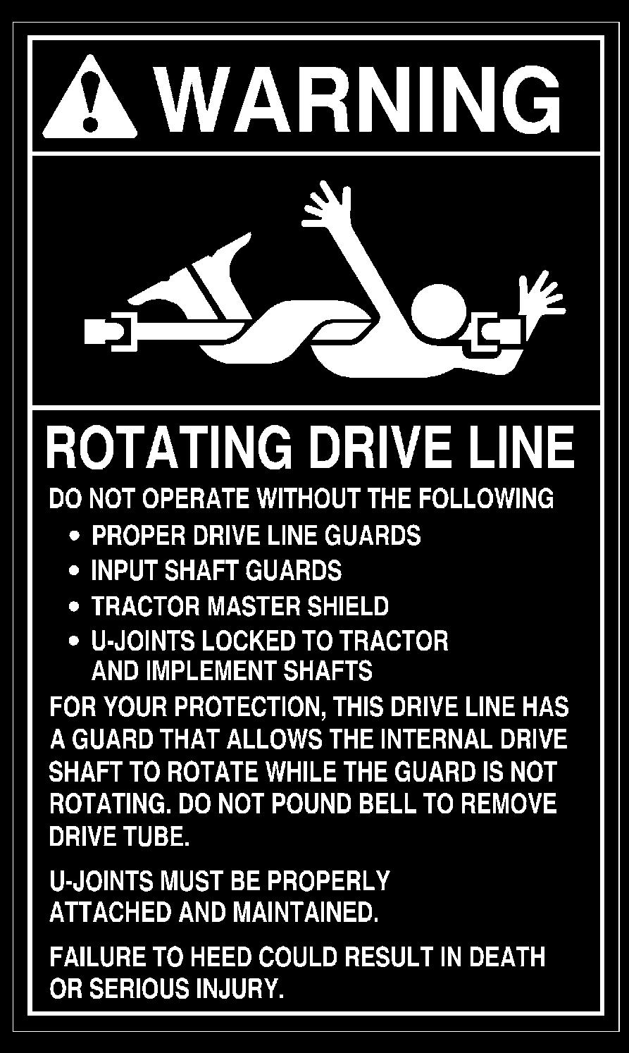
12 CHAPTER 4 SAFETY The above Safety Alert Symbol means ATTENTION! BECOME ALERT! YOUR SAFETY IS IN- VOLVED! It stresses an attitude of Heads Up for Safety and can be found throughout this Operator s Manual and on the machine itself. BEFORE YOU ATTEMPT TO OPERATE THIS EQUIPMENT, READ AND STUDY THE FOL- LOWING SAFETY INFORMATION. IN ADDI- TION, MAKE SURE THAT EVERY INDIVIDUAL WHO OPERATES OR WORKS WITH THIS EQUIPMENT, WHETHER FAMILY MEMBER OR EMPLOYEE, IS FAMILIAR WITH THESE SAFETY PRECAUTIONS. Our Company ALWAYS takes the operator and his/her safety into consideration when designing its machinery and guards exposed moving parts for his/her protection. However, some areas can not be guarded or shielded in order to assure proper operation. This Operator s Manual, and decals on the machine, warn of additional hazards and should be read and observed closely. DANGER DANGER indicates an imminently hazardous situation which, if not avoided, will result in death or serious injury. WARNING WARNING indicates a potentially hazardous situation which, if not avoided, could result in death or serious injury. CAUTION CAUTION indicates a potentially hazardous situation which, if not avoided, may result in minor or moderate injury. It may also alert against unsafe practices. MANDATORY SAFETY SHUTDOWN PROCEDURE BEFORE unclogging, cleaning, adjusting, lubricating or servicing the unit: 1. Disengage the tractor PTO. 2. Shut off the tractor engine, place the tractor transmission in park and/or lock brake pedals to prevent any tractor movement. 3. On Auto-Electric control equipped balers, BEFORE leaving the tractor seat to perform any function or maintenance, push POW- ER keypad to turn off power to the control. 4. Remove the starter switch key and take it with you when leaving the tractor seat. 5. Wait for all movement to stop. 6. Remove the telescoping drive and ALL power connections from the tractor. ONLY when you have taken these precautions can you be sure it is safe to proceed. Failure to follow the above procedure could lead to death or serious bodily injury. ADDITIONAL SAFETY REMINDERS Some photographs, used in this manual, may show doors, guards or shields open or removed for illustration purposes ONLY! BE SURE that all doors, guards and shields are in their proper positions and securely attached BEFORE operating this unit! ALWAYS wear safety glasses with side shields when striking metal against metal! In addition, it is recommended that a softer (non-chipable) material be used to cushion the blow. Failure to heed could result in serious injury to the eyes or other parts of the body! NEVER use your hands to search for hydraulic fluid leaks; use a piece of cardboard. Escaping fluid under pressure can be invisible and penetrate the skin causing serious injury! If any fluid is injected into your skin, see a doctor at once! Injected fluid MUST BE surgically removed by a doctor familiar with this type of injury or gangrene may result /CP Printed in U.S.A.
13 SAFETY (Continued) ALWAYS follow state and local regulations regarding use of a safety chain and transport lighting when towing farm equipment on public highways! A safety chain should always be used to retain the connection between the towing and towed machines, in the event of separation of the primary attaching system! BE SURE to check with local law enforcement agencies for your own particular regulations. Unless otherwise prohibited, use a Slow moving Vehicle (SMV) emblem. Only a safety chain (NOT an elastic or nylon/plastic tow strap) should be used to retain the connection between the towing and towed machines, in the event of separation of the primary attaching system. Refer to the Optional Features & Accessories chapter for safety chain. Good safety practice dictates that you NEVER tow an implement that does not have brakes, unless the towing vehicle weighs at least one-and-one half (1-1/2) times the weight of the towed implement and its load. For any public highway travel and to be in compliance with this rule, BE SURE that your tractor is heavy enough to counterbalance the weight of the baler and a full-sized bale. Limit towing speed to 20 mph (32 km/h). Always use adequate lights or safety warnings when transporting the machine on public roads and after dark. Check with the local law enforcement agencies for specific requirements. BE SURE that the telescoping PTO drive rotates freely inside the drive shield tubes at all times. Balers are provided with two different types of telescoping drives; one drive has metal shield tubes and the other has plastic shield tubes. The drive with plastic shield tubes must be anchored to a hole in a part of the baler frame with the tie-down chain provided. The drive with metal shield tubes MUST NOT be anchored. Bales made with the Round Baler are LARGE, CYLIN- DRICAL and HEAVY. Serious personal injury or property damage could result if the bales are not carefully and properly handled. NEVER eject or store bales where they could possibly roll downhill. To ensure continued safe operation, replace damaged or worn-out parts with genuine GEHL service parts, BEFORE attempting to operate this equipment. Our Company does NOT sell replacement tires. In addition, tire mounting, service or inflation can be dangerous. Whenever possible, trained personnel should be called to service and/or mount tires, following the tire manufacturer s instructions. If you do not have such instructions, contact your tire dealer or our Company. In any event, to avoid possible fatal or serious injury, follow the specific directives given in the Service chapter of this manual. BE SURE to review and comply with ALL safety recommendations set forth in the tractor operator s manual. REMEMBER, it is the owner s responsibility for communicating information on the safe use and proper maintenance of this machine. Printed in U.S.A /CP0600


14 SAFETY (Continued) /CP Printed in U.S.A.
")

15 SAFETY (Continued) Printed in U.S.A /CP0600


16 SAFETY (Continued) /CP Printed in U.S.A.
")


17 SAFETY (Continued) Printed in U.S.A /CP0600


18 SAFETY (Continued) Under Shield /CP Printed in U.S.A.
")


19 SAFETY (Continued) Printed in U.S.A /CP0600
20 SAFETY (Continued) Quick Wrap System Models Only /CP Printed in U.S.A.
21 SAFETY (Continued) Quick Wrap System Models Only Printed in U.S.A /CP0600

22 CHAPTER 5 CONTROLS & SAFETY EQUIPMENT Each variable chamber Round Baler is provided with several similar features for operator safety and convenience. CAUTION Become familiar with and know how to use ALL safety devices and controls on this machine BEFORE attempting to operate the unit. Know how to STOP machine operation BE- FORE starting it. FRONT GUARD ASSEMBLY (Fig. 1) The Front Guard assembly serves as a barrier and a reminder to KEEP AWAY from the front of the Baler, while it is running. Furthermore, do NOT attempt to place an arm or leg between the Front Guard Bars,while the Baler is operating. The Front Guard assembly can be unbolted at the bottom and pivoted out of the way when necessary. BE SURE the Front Guard assembly is restored to its original position and secured BEFORE resuming operation. FENDER/TWINEBOX ASSEMBLIES (Figs. 2 & 3) WARNING NEVER attempt to step up on, stand on or ride on the twineboxes, or any other part of the baler, while the baler is moving or being operated Front Guard Assembly Fig. 1 WARNING NEVER remove the front guard assembly from the Baler. NEVER stand on or place your arms or legs through the front guard bars while the baler is running or moving. ALWAYS exercise the MANDATORY SAFETY SHUT- DOWN PROCEDURE (page 10), BEFORE approaching the front guard assembly. 1 Operator s Manual location on underside of Twinebox Lid Fig. 2: Twinebox & Fender on Right Side The Fender/Twinebox Assemblies provide protection for the Tires, a place to store twine, a place to store the Operator s Manual on the right side, and a place to stand on to engage or disengage the Shuttle Locks /CP Printed in U.S.A.
23 Chapter 5 Controls & Safety Equipment 1 1 Gate Cylinder Lockout Valve Fig. 3: Twinebox & Fender on Left Side GATE CYLINDER LOCKOUT VALVE 1 Gate Cylinder Lockout Valve in Open Position 2 Tailgate Lock Decal Fig. 4 WARNING ALWAYS place the gate cylinder lockout valve in the locked position BEFORE working inside the bale chamber or under the gate when the gate is open. After SN and SN (Figs. 3, 4 & 5) The Baler is equipped with a Gate Cylinder Lockout Valve that is used to lock and hold both Gate Lift Cylinders inoperable in any position. The Lift Cylinders are locked in position when the Gate Cylinder Lockout Valve Handle is turned to the vertical position (Fig. 5). The Lift Cylinders are free to operate when the Valve Handle is turned to the horizontal position (Fig. 4). 1 Gate Cylinder Lockout Valve in Locked Position 2 Tailgate Lock Decal Fig. 5 Printed in U.S.A /CP0600
 The Baler is equipped with a Gate Cylinder Lockout Valve that is used to lock and hold both Gate Lift Cylinders inoperable in any position.")
24 Chapter 5 Controls & Safety Equipment Before SN and SN (Figs. 3, 6 & 7) The Baler is equipped with a Gate Cylinder Lockout Valve that is used to lock and hold both Gate Lift Cylinders inoperable in any position. The Lift Cylinders are locked in position when the Gate Cylinder Lockout Valve Handle is depressed into the valve body and the position Indicator is in the vertical position (Fig. 7). The Lift Cylinders are free to operate when the Valve Handle is pulled out from the valve body and the position Indicator is pointing to the Baler and is in the notch (Fig. 6). 1 Gate Cylinder Lockout Valve in Locked Position 2 Indicator Vertical Fig Gate Cylinder Lockout Valve in Open Position 2 Indicator in Notch 3 Tailgate Lock Decal 4 Red Reflector Fig. 6 SHUTTLE LOCKS (Fig. 8) Shuttle Locks are provided on both sides of the Baler to remove Belt tension while cleaning or servicing the Baler. Engage both Locks when replacing or re-lacing the Belts and when removing build-up from around the Rollers. Step up on the left or right Twinebox in order to reach the Shuttle Locks. WARNING NEVER have the PTO engaged while the shuttle locks are engaged. ALWAYS engage both shuttle locks to make sure that belt tension is completely locked out. 1 Shuttle Lock Location (One Each Side) Fig. 8: Gate in Open Position FIRE EXTINGUISHER WARNING If a fire occurs eject the bale from the baler IM- MEDIATELY, move the baler up-wind 30 feet (10 m) or more away from the ejected bale, shut off the tractor engine and proceed to put out the fire with a fire extinguisher /CP Printed in U.S.A.


25 Chapter 5 Controls & Safety Equipment There is always the possibility of fire when handling dry forage materials. GEHL Company recommends that to limit the damage to the Baler and/or tractor in case of a bale fire, a five gallon or larger, pressurized water type, fire extinguisher should be mounted on the tractor or Baler, as a minimum protection. NOTE: A five gallon extinguisher should be sufficient to put out small fires that are burning the dry material that remains in the Baler, after the bale is ejected. However, this size extinguisher is insufficient to put out even a small fire in the bale. Front Belt Guard (Fig. 9) The Front Belt Guard is provided to shield the area of Belt travel around the Drive Roller and Idler Roller. BE SURE the Guard is properly positioned and secured before operating the Baler. 1 WARNING The pressurized water fire extinguisher DOES NOT replace the dry chemical fire extinguisher on the tractor (if so equipped). NEVER use a water type fire extinguisher on electrical or fuel fires. Furthermore, to reduce the possibility of a fire, keep crop build-up to a minimum, especially on the roller ends, the chain drives (behind the hinged shields) and in the pickup drive area. GUARDS, DOORS & SHIELDS Whenever possible and without affecting machine operation, Guards, Shields and/or hinged Covers have been used on this equipment to protect potentially hazardous areas. In many places, Decals are also provided to warn of potential dangers as well as display special operating procedures. 1 Front Belt Guard Fig. 9 Large Hinged Guard Doors & Removable Side Shields (Fig. 10) Large Hinged Doors and Removable (hinged with Latch on later models) Side Shields are provided on both sides of the Baler to cover and protect drives and adjustable portion of the TDC system. The Side Shields should be installed (latched on later models) and the doors should be closed and latched whenever the Baler is running WARNING Read and observe ALL Warnings on the unit BEFORE operating it. Do NOT attempt to operate this equipment unless ALL factory installed Guards and Shields are properly secured in place. BEFORE proceeding to perform any work on the Baler and, BEFORE removing or opening any Shields, BE SURE to exercise the MANDATORY SAFETY SHUT- DOWN PROCEDURE (page 10). Also, BE SURE to reinstall and/or close ALL Shields BEFORE operating the Baler. 1 Large Hinged Guard Doors (Both Sides) 2 Side Shields (Both Sides) 3 Side Shield Latch (Behind Shield, later models) Fig. 10 Printed in U.S.A /CP0600
 The pinch point of the Pickup Drive Belt is shielded with a Guard. BE SURE that the Guard is always securely fastened in place while operating the Baler.")
 A Hitchjack is furnished with the Baler to support the machine when the tractor is disconnected as well as facilitate aligning the Hitch Clevis with the tractor drawbar for hookup.")
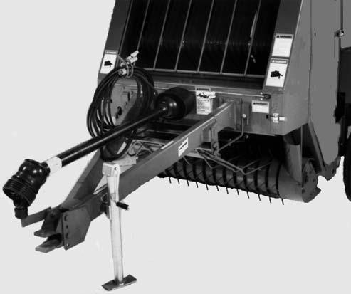
26 Chapter 5 Controls & Safety Equipment WARNING 1 When working inside the guard doors or side shields, BE SURE to exercise the MANDATO- RY SAFETY SHUTDOWN PROCEDURE (page 10). Pickup V-Belt Guard (Fig. 11) The pinch point of the Pickup Drive Belt is shielded with a Guard. BE SURE that the Guard is always securely fastened in place while operating the Baler Storage Position for Hitchjack on Hub 2 PTO Supported on CV Stand 3 Hitchjack in Supporting Position Fig Pickup V-Belt Guard Fig. 11 HITCHJACK (Fig. 12) A Hitchjack is furnished with the Baler to support the machine when the tractor is disconnected as well as facilitate aligning the Hitch Clevis with the tractor drawbar for hookup. When the Jack is NOT being used to support the Baler and to prevent it from being damaged by the tractor tire, it can be removed and relocated to a Storage position on the inside of the Drawbar on the left side. Wrap the Chain around the Jack Handle, before inserting the Locking Pin through the Hub holes, to prevent the Handle from dragging on the ground. WARNING BE SURE the locking pin is entirely and properly inserted through both hub holes on the jackstand BEFORE disconnecting the baler from the tractor. REVERSING WRENCH (Figs. 13 & 14) The Round Baler is provided with a Reversing Wrench Handle for manually rotating the Transmission Output Shaft. When NOT in use, the Wrench should be in a stored position located underneath the left Hinged Guard Door (Fig. 14) /CP Printed in U.S.A.
 Reservoir Fig.")
 The Automatic Bale Control System model Baler comes equipped from the factory with the Automatic Bale Control System factory installed.")

27 Chapter 5 Controls & Safety Equipment WARNING 1 ALWAYS exercise the MANDATORY SAFETY SHUTDOWN PROCEDURE (page 10) BEFORE using the reversing wrench. Also, BE SURE to replace the wrench in its storage location BE- FORE resuming baler operation Pressure Relief Valve 2 Total Density Control (TDC) Reservoir Fig Reversing Wrench Being Used to Reverse Drive 2 Transmission Output Shaft Fig AUTOMATIC BALE CONTROL SYSTEM (OPTIONAL) (Fig. 16) The Automatic Bale Control System model Baler comes equipped from the factory with the Automatic Bale Control System factory installed. The system provides an information center and Baler control for the operator from the tractor. If the Baler is equipped with the Quick Wrap option, the operator may also change from twine tying to a netting wrap without having to leave the tractor. 1 Reversing Wrench In Storage Position 2 Hinged Guard Door Fig. 14: Left Side View of Baler TDC PRESSURE RELIEF (Fig. 15) A Pressure Relief Valve is provided on top of the TDC Reservoir to automatically release excessive (beyond 300 PSI or 2100 kpa) pressure build-up. The Relief Valve helps to prevent TDC system component damage. The Relief Valve is covered with a protective plastic cap that should remain in place at all times. Fig. 16: Auto-Electric Control Module Printed in U.S.A /CP0600

28 Chapter 5 Controls & Safety Equipment AUTOMATIC TWINE WRAP SYSTEM (Fig. 17) The Automatic Twine Wrap model Baler comes equipped with the Auto Twine Wrap Control System dealer installed. The system provides for automated twine wrapping of the bale and as an information center during the baling operation. Bales may also be wrapped in a manual mode. This system is NOT for use on Balers that are equipped with a Net Wrap system. 1 1 Twine Arm Positioning Switch Fig. 18: Manual Twine Control Box SAFETY CHAIN & TRANSPORT LIGHTING (Figs. 19 & 20) CAUTION Fig. 17: Auto Twine Control Module MANUAL TWINE WRAP SYSTEM (Fig. 18) The manual tie model Baler comes with a Manual Twine Wrap system that is dealer installed. A Baler so equipped will allow manual control of the twine tying cycle from the tractor. ALWAYS follow state and local regulations regarding a safety chain and transport lighting when towing farm equipment on a public highway! BE SURE to check with local law enforcement agencies for your own particular regulations. Unless otherwise prohibited, use a Slow-Moving Vehicle (SMV) emblem. Only a safety chain (NOT an elastic or nylon/plastic tow strap) should be used to retain the connection between the towing and towed machine, in the event of separation of the primary attaching system. As required or when desired, the Baler should be equipped with the optional safety chain for transporting the unit on public highways. The chain should be routed as shown in Fig. 19. The Balers are equipped with Transport Lights, which are standard equipment /CP Printed in U.S.A.

 5 Chain Secured Around Tractor Frame Member 6 Safety Chain")
29 Chapter 5 Controls & Safety Equipment The Telescoping PTO Drive is provided with a Springloaded Locking Device on each end to positively lock the Drive connections onto the tractor PTO shaft and the Baler Drive Input Shaft. Depress the Locking Device, against the Spring tension, and slide the Yoke onto its respective Drive Shaft. Release the Locking Device and move the Yoke ahead or back until the Lock engages into the groove of its respective Shaft Telescoping PTO Drive with Drive Shield Tubes 2 CV Stand in Storage Position 3 Locking Hitchbolt 4 Drawbar Clevis (Provided) 5 Chain Secured Around Tractor Frame Member 6 Safety Chain Attached Around Baler Frame Fig. 19: Optional Safety Chain Telescoping PTO Drive with Drive Shield Tubes 2 Spring-loaded Locking Device Placed onto CV Stand Fig Transport Lighting Fig. 20 TELESCOPING PTO DRIVE (Figs. 19 & 21) The Telescoping PTO Drive is designed to rotate freely inside the Drive Shield Tubes. NOTE: ALWAYS orient and attach the PTO Drive with the CV end coupled to the tractor PTO shaft. WARNING BE SURE that the telescoping drive rotates freely inside the drive shield tubes at all times. BE SURE the telescoping drive connections are properly secured to the tractor PTO shaft and baler drive input shaft BEFORE starting the tractor engine. Also, BE SURE the tractor master shield is in place and properly secured BEFORE starting the tractor. NOTE: For your convenience when the Baler is disconnected from the tractor, the PTO can be placed onto the CV Stand, mounted on the right side of the Hitch Clevis assembly. The CV Stand is designed to be pivoted out of the way when NOT in use. In addition, when transporting the Baler, leave the Telescoping PTO Drive attached to the tractor. If the PTO is NOT connected, it should be disconnected from the Baler and stored in or on the towing vehicle. Printed in U.S.A /CP0600
30 CHAPTER 6 OPERATION 1 Shuttle Stop 2 Shuttle Chain Adjustment Bolt 3 Shuttle Lock in Storage Position 4 Shuttle Chain 5 Density Cylinder Sprocket 6 Density Cylinder 7 Gate Cylinder 8 Bale Starter Torsion Spring 9 Scraper Roller Overrunning Clutch Sprocket Roller Driven Sprocket 11 Adjustable Wheel Spindle 12 8 Roller Drive Sprocket 13 Transmission Drive Sprocket 14 8 Floor Roller Idler Floor Roller Idler 16 Spring-loaded idler 17 Packing Roller Spring Adjustment 18 Packing Roll Stop Adjustment Bolt 19 Windguard 20 Windguard Latch 21 Left Twine Feed Sensor* 22 Baler to Tractor Connector 23 Tractor Battery 24 Tractor Control Module 25 Bale Size Sensor* 26 Implement Module* 27 Shuttle Return & Full Size Bale Sensor* 28 Gate Latch Sensor* *Auto-Electric Models ONLY Fig. 22: Component Identification - Left Side /CP Printed in U.S.A.
31 Chapter 6 Operation 1 Overfill Clutch Actuator 2 Excessive Pressure Relief & Adapter 3 Valve Stem 4 Shuttle Lock (Engaged) 5 Shuttle 6 Shuttle Stop 7 TDC Reservoir Sight Tube 8 Belt Drive Roller 9 Re-wrap Roller 10 Belts 11 Valve Trip Mechanism 12 Adjustable Relief Valve 13 Density Cylinder 14 Bale Starter 15 Packing Roll Compression Spring 16 Pickup Height Adjustment Crank 17 Idler Assembly Pivot 18 Scraper Roller 19 Pickup Stop 20 Packing Roller 21 Packing Roller Drive Chain 22 Pickup Driven Sheave 23 Pickup Idler Pulley 24 Cable From Overfill Clutch to Stop Pickup 25 8 Lower Roller Lower Roller 27 Bale Starter Roller 28 Adjustable Gate End Roller 29 Gate Latch 30 Adjustable Gate Latch Lift Rod 31 Belt Tracking Roller 32 Gate Cylinder 33 Pressure Gauge (TDC Reservoir) 34 Trip Arm 35 Trip Spacer 36 Density Cylinder Sprocket 37 TDC Reservoir 38 Bale Counter (Manual Balers ONLY) 39 Right Twine Feed Sensor (Auto-Electric ONLY) 40 Pickup Flotation Spring Fig. 23: Component Identification - Right Side Printed in U.S.A /CP0600
32 Chapter 6 Operation HOW BALER FUNCTIONS (Figs. 22 & 23) Crop material is picked off the ground by the 4-Tinebar, Closed-style Pickup and delivered to the throat of the unit where it is pressed by the Packing Roller against the Lower Roller. The Rollers then carry the crop to the back of the unit where the crop meets the Belts which are traveling toward the front of the unit. The Belts carry the crop forward and over the top of the lower incoming mat of material until it comes in contact with the Bale Starter Fingers. The Fingers deflect material down into the incoming mat of material to form a roll of crop material or bale core. As the round core of material gets larger in size, the Bale Starter is lifted from the area to avoid contact with the bale. As the bale increases in size, the additional Belting, required to wrap the bale, is released by the Belt Shuttle as it moves toward the rear of the Baler. Belt tension and bale density control is governed by the Total Density Control (TDC) system. The windrow and driving pattern of the Baler operator determines how well the material is distributed across the bale. NOTE: It may be necessary to weave from one side of the windrow to the other in order to properly distribute crop into the baling chamber. On manual control models, when the Bale Size Indicator reaches the preferred size, the twine can be wrapped around the bale. Once tied, the bale is ejected by opening the Gate and the process of forming another bale can be restarted. The maximum bale size is 5 (for RB1475) or 6 (for RB1875), NOTE: It may be necessary to back up several feet before ejecting the bale to allow room to close and latch the tailgate without contacting the crop windrow. HOW TDC SYSTEM FUNCTIONS (Figs. 24, 25 & 26) The Belt Tension and subsequent bale density is controlled by the Total Density Control (TDC) system. The major components of this system include a Reservoir, two Density Cylinders, an adjustable Pressure Relief Valve, and a Manifold with a Trip Mechanism. This unique TDC system is self-contained and is completely independent of the tractor hydraulic system. The TDC system supplies a tensioning force to the Belts which, in turn, exerts a compressive force on the forming bale. During the initial bale forming stage, the force exerted by the Density Cylinders onto the Belts is directly related to the air pressure in the Reservoir. As the bale increases in size, the additional Belting required is released by the Belt Shuttle as it moves toward the rear of the Baler. This rearward travel of the Belt Shuttle extends the Density Cylinders and forces hydraulic fluid out of the Cylinders, through a Manifold and into the Reservoir. This additional fluid further compresses the air in the Reservoir and causes an increase of pressure resulting in Belt tension. ÎÎ 1 Air Pressure 2 Pressurized Reservoir 3 Oil 4 Pressure Reading of 140 to 150 PSI (980 to 1050 kpa) (Shuttle Returned) 5 Adjustable Relief Valve Setting 150 to 450 PSI for RB1475 & 150 to 550 PSI for RB1875 (1050 to 3,150 kpa for RB1475, 1050 to 3850 kpa for RB1875) 6 To Left Cylinder 7 Shuttle Cylinder Fig. 24: Core Formation Detail As the Cylinders continue to extend, the Valve Trip Mechanism is contacted by the Trip Spacer on the Trip Arm of the right Density Cylinder Clevis. As the Valve Trip Mechanism is triggered, the free flow path through the Manifold is blocked off and the hydraulic fluid is redirected through the adjustable Pressure Relief Valve on its way to the Reservoir. The Relief Valve works to create a pressure differential between the Density Cylinders and the Reservoir. This means that the fluid pressure in the Density Cylinders has to reach a preset value above the pressure in the Reservoir before the Relief Valve will relieve and allow the fluid to pass through to the Reservoir /CP Printed in U.S.A.
33 Chapter 6 Operation As the bale continues to grow and the Cylinders continue to extend, the TDC system continues to function in the manner previously described. When the bale is ejected from the Baler, the pressure in the line from the Density Cylinders to the Relief Valve drops below the pressure in the Reservoir. This causes a reverse flow of hydraulic fluid from the Reservoir back into the Density Cylinders. The Cylinders are retracted which in turn restores the Shuttle, the Belts and the Valve Trip Mechanism to their original positions. The TDC system is once again ready to start forming another bale. BALE FORMATION & STORAGE TIPS The following information provides guidelines for using the Round Baler to get the most out of your crop and investment. ÎÎ ÎÎ ÎÎ 1 Air Pressure 2 Pressurized Reservoir 3 Oil 4 Pressure Reading of 170 to 290 PSI (1190 to 2030 kpa) 5 Adjustable Relief Valve Setting 150 to 450 PSI for RB1475 & 150 to 550 PSI for RB1875 (1050 to 3,150 kpa for RB1475, 1050 to 3850 kpa for RB1875) 6 To Left Cylinder 7 Shuttle Cylinder Fig. 25: Bale Building (Beyond Core Formation) Detail RB1475 & 1875 Table of Approximate Core Formation (Diameter Ranges in Inches) for Various Trip Arm and Manifold Settings 1 Air Pressure 2 Pressurized Reservoir 3 Oil 4 Pressure Reading of 290 to 290 PSI (1050 to 2030 kpa) 5 Adjustable Relief Valve Setting 150 to 450 PSI for RB1475 & 1050 to 550 PSI for RB1875 (1050 to 3,150 kpa for RB1475, 1050 to 3850 kpa for RB1875) 6 15 PSI (105 kpa) 7 To Left Cylinder 8 Shuttle Cylinder Fig. 26: Bale Ejecting & Shuttle Return Detail RB1475 Trip Arm Position Diameter of Bale Core 1 (Top) (Bottom) 27 Printed in U.S.A /CP0600
34 Chapter 6 Operation A Small Core with High Density Crop (See Curve 1) B Small Core with Low Density Crop (See Curve 2) C Large Core with High Density Crop (See Curve 3) D Large Core with Low Density Crop (See Curve 4) 1 Curve for Core Formation A 2 Curve for Core Formation B 3 Curve for Core Formation C 4 Curve for Core Formation D 5 Outer Crop (Relief Pressure-controlled) 6 Core Formation (Air Pressure-controlled) 7 Increasing Bale Diameter 8 Increasing TDC System Bale Forming Pressure Fig. 27: Bale Density & Formation Detail /CP Printed in U.S.A.
35 Chapter 6 Operation Optimum Conditions & Bale Density (Fig. 27) Optimum haying conditions are a combination of crop maturity and moisture content. Because of changing weather conditions, NOT all hay can be baled under ideal circumstances. The TDC system enables the Baler to adapt to these less than ideal conditions. In particular, the density of the bales can be adjusted to be more compatible with baling conditions. As moisture content increases, the bale density can be decreased. Using the illustration and table provided for a reference, several types of bales can be formed by altering either or both the Trip Spacer on the Trip Arm which is connected to the right Density Cylinder or the Relief Valve pressure setting. Changing the Trip Spacer location to one of the other lower holes, progressively increases the core diameter by delaying activation of the Valve Trip Mechanism. Bale density can be adjusted for different crop conditions and moisture contents by adjusting the Relief Valve setting. Turning the End Disc assembly clockwise into the Valve Body increases the Relief Pressure and bale density. The adjusted setting can then be locked in place by turning the Locking Ring clockwise until it is snug against the Valve Body. Bale Handling & Storage WARNING Bales made with a Round Baler are LARGE, CYLINDRICAL and HEAVY! Serious personal injury or property damage could result if the bales are not carefully and properly handled. MAKE SURE the bale will not roll when ejected from the baler. BE SURE that the tractor used with any bale handler is large enough to safely handle the weight of the bales. Front or rear counter-weights may be required. Using a bucket style front end loader to move bales creates a hazard, because the bale can roll out of the bucket and down the loader arms onto the operator. Generally, agricultural tractor Roll-over Protective Structures (2 Post ROPS) are not intended to protect against falling bales. Do NOT lift round bales with the standard loader unless you have proper bale restraining devices. Because the bales are cylindrical and very heavy, special care MUST be exercised when ejecting them and storing them to keep them from starting to roll. When the bales are moved, make sure that the original bottom of the bale stays at the bottom. When moving bales to a storage area, observe the following recommendations to minimize crop loss: 1. Select a well-drained area with complete exposure to the sunlight. 2. Place the axis of the bales north and south so the sun can dry out the cylindrical surface of the bale as it travels from east to west. 3. Where space allows, set several bales in a row with their ends pushed tightly together to form a long cylinder. Make sure that you do NOT form a water dam using too many bales in a row without skipping a space. Make sure to always maintain a clear path for the water to travel away from the bales. 4. Keep the rows of bales far enough apart so that one row will NOT overshadow the adjoining row and cut down on exposure to full sunlight. 5. When bales are stored outside in conditions of exceptionally high rainfall (especially driving rains), spoilage due to water penetration can be reduced by placing the shingled cylindrical surface of the bale in the direction of prevailing rain or wind. The shingled surface can be determined by running your hand along the edge of the bale. On the shingled surface, your hand will slide smoothly. The unshingled surface will offer more resistance to your hand movement. Baling After transporting the Baler to the field, adjust the Pickup height according to crop conditions and land contour; refer to the Pickup Flotation topic in the Adjustment chapter of this manual for details. The Baler Pickup should be run as high off the ground as possible while still being able to completely pick up all of the crop. IMPORTANT: The Pickup assembly MUST be carried off the ground. Running the Pickup too low to the ground will result in excessive Tine wear or breakage and possible damage to the Pickup Stripper Bands and Headers, Cam and Cam Bearings. Move the Baler into position with respect to the windrow and BE SURE to check the path in front of the Pickup and ahead of the Baler before starting to bale. Then, start the PTO, bring the tractor RPM up to the desired operating speed and begin baling. Printed in U.S.A /CP0600
36 Chapter 6 Operation If the windrow has been prepared to less than the full width of the Bale Chamber, it will be necessary to drive the Baler in a weaving fashion to fill the Chamber and start the bale core. If the windrow has been prepared for the full width of the Pickup, either 45 to 52 (1143 to 1321 mm) for an RB1475 or 61 to 68 (1549 to 1727 mm) for an RB1875, the Baler can be driven straight down the windrow while observing that the bale starts and continues to form properly. To obtain the most uniform bales, the windrow should, wherever possible, be made at or slightly larger than the Bale Chamber width. When baling a windrow which is about 1/2 the width of the Bale Chamber and after the core has started, stop the weaving process and drive straight with the windrow entering the Pickup as far to one side as possible. Continue driving the Baler with the windrow entering on one side until the rotating bale is approximately 3 to 4 (76 to 102 mm) higher on one side than the other. Then, quickly cross over so that the windrow enters on the other side of the Pickup and continue filling that side until it is 3 to 4 (76 to 102 mm) higher than the other side. Continue crossing over from side to side until a full-sized bale is formed. When baling a windrow which matches the full width of the Bale Chamber, drive straight down the windrow until the desired full-sized bale is formed. IMPORTANT: Continuous feeding of material provides for smoother starting and better bale formation. Avoid non-cylindrical bales and bales with loosely packed outside edges. Both conditions can allow the Belts to fall off the ends of the bale and possibly tear out the Belt Lacing Hooks. In addition, this type of bale will weather poorly. Proper material preparation is a very important factor in making good-shaped bales. Refer to the Preparing for Field Operation chapter of this manual for further details. Baylage (High Moisture Hay) (RB1475 Only) NOTE: Anyone experimenting with this type of storage procedure, for the first time, should do so with limited samples, to minimize potential losses. NOTE: Due to the extremely HEAVY bale that results from high moisture baling, we recommend that bale sizes be kept under a 4 ft (1.2 m) diameter. It is further recommended that Balage baling be limited to using only an RB1475 Baler and equipping it with an accessory Silage Scraper Kit. Refer to the Optional Features & Accessories chapter for ordering information. BALE SIZE VISUAL INDICATOR (MANUAL & AUTOMATIC TWINE CONTROL MODELS) (Fig. 28) The Bale is full-size when it reaches 5 feet (1.5 m) in diameter for the RB1475 Baler or 6 feet (1.8 m) in diameter for the RB1875 Baler. As a matter of personal preference, the bale forming process can be stopped at any time before this size. For this reason, the Bale Size Visual Indicator is provided as a visual aid to forming consistent sized bales. 1 1 Bale Size Visual Indicator 2 Pointer Fig. 28 OVERFILL PROTECTION (Figs. 22 & 23) The Baler is designed with an Overfill Clutch mechanism which automatically stops the Pickup when the bale becomes oversized. If the bale becomes oversized, the Shuttle will activate the Overfill Clutch Actuator which is linked by a Cable to the Pickup Drive to stop the Pickup and prevent damaging the Baler. When this happens, simply back the Baler out of the windrow and tie or wrap the bale in the normal manner /CP Printed in U.S.A.
37 Chapter 6 Operation MANUAL TWINE WRAP (Figs. 28 & 29) NOTE: The procedure described is the manual sequence. The entire process of wrapping the bale with twine is done from the tractor seat. The position of the Pointer on the Bale Size Indicator can be used as a fairly accurate gauge for forming the desired size bale. When the desired size bale is formed, stop Baler forward travel. Then, swing the Twine Arm so that it is straight back. NOTE: The Twine Arm is actuated by moving the Twine Arm Positioning Switch to the FOR- WARD position to move the Twine Arm from right to left. Moving the Twine Arm Positioning Switch to the REV (Reverse) position moves the Twine Arm from left to right. NOTE: By moving the Twine Arm to the middle of the Baler, appropriate lengths of twine are brought out for starting to wrap a new bale. Then, drive forward again to take in a small amount of material to start feeding the twine into the Baler. DANGER NEVER attempt to clean or manually feed the baler when it is running. Material feeds into the baler faster than you can react to release it. You may become entangled in moving belts, pick-up or rollers. Failure to heed can result in death or serious injury. When the twine can be seen moving into the Twine Arm, stop Baler forward travel. Allow the twine to make at least one full wrap in this location and then move the Twine Arm to the left side. NOTE: Moving the Twine Arm all the way to the left engages and locks the Twine Cutoff Jaws in the open position. NOTE: Normally, the bale can be adequately tied with two wraps of twine on the left side, several wraps across the center of the bale and two wraps on the right side. If the material being baled is slippery, it will be beneficial to place two wraps of twine on the center of the bale before moving to the left side in order to prevent the twine from sliding off the end of the bale. It may also be necessary to adjust the positions of the end wraps depending on the crop being baled. When the Twine Arm returns all the way to the right, the Twine Jaws will snap closed and the twine will be cut. The wrapped bale can now be ejected from the Baler and baling can resume. 1 Twine Arm Positioning Switch Fig. 29 AUTOMATIC TWINE WRAP SYSTEM Features The Auto Twine Wrap Control System exhibits the following features and characteristics: 1. AUTO/MANUAL Mode Selection - fully automatic tie system or manual tie system. 2. Continuous moving Twine Arm distributes twine in a helical pattern across the bale. 3. A daily bale counter which can be reset to Zero (0) 4. A lifetime bale counter which cannot be reset 5. The error message SEt is displayed when the twine wrapping system is not functioning properly (Refer to the Troubleshooting chapter). 1 Printed in U.S.A /CP0600
38 Chapter 6 Operation 6. Two spaced audible tones are sounded when the tie cycle starts. 7. The message tie is displayed while the system is in the twine tie sequence. 8. One audible tone is sounded and the message OPEn GAtE is displayed when the tie sequence is through and the Baler is ready for the bale to be discharged. The message OPEn GAtE remains displayed until the bale is discharged. 9. One audible tone is sounded when the Tailgate is first opened and then repeated every eight seconds while the Tailgate remains open. 10. Two quick audible tones are sounded when the Tailgate is closed and latched Operation The Control Module is a monitor and controller for the Twine Arm. When a bale is formed, a sequence is started that drives the Twine Arm across the face of the bale. The twine is applied in a predetermined helical pattern across the face of the bale and is designed to apply extra twine on each bale end. Bales can be tied in a manual or fully automatic mode. The Control Module also keeps a daily and lifetime count of bales made. NOTE: This Auto Twine Control is NOT intended for use on Balers equipped with Quick Wrap. Controls Control Module (Fig. 30) Mode Switch (AUTO/MANUAL) 2 Manual Mode Actuator Switch (EXTEND/NEUTRAL/RETRACT) 3 POWER Switch (ON/OFF) 4 Channel 5 Symbol Twine Arm Position 5 Channel 4 Symbol Twine Arm Pause 6 INCREASE Key 7 Channel 3 Symbol Twine End Wraps 8 DECREASE Key 9 Harness Connector 10 Channel 2 Symbol Twine Density (No. of Wraps Across Bale) 11 Channel 1 Symbol Bale Count 12 Tailgate Status Symbol (Closed) 13 Tailgate Status Symbol (Open) 14 Digital Display 15 SELECT Key (Channel Control) Fig. 30: Automatic Twine Wrap Control Module Component Locations /CP Printed in U.S.A.
39 Chapter 6 Operation POWER Switch (Fig. 31) Fig. 31: Power Switch Actuator Switch (Fig. 33) This Toggle Switch is used to direct power to the Actuator to manually EXTEND or RETRACT the Twine Arm. NOTE: The Mode Switch (Fig. 32) MUST BE set to MANUAL for this Switch to function. From MANUAL Position of Mode Switch This Toggle Switch is used to power up and shut down the Auto Twine System. ON Move the Switch Handle to the right to turn Control Module on and power up the auto twine control system. OFF Move the Switch Handle to the left to power down the control system. This will cause the display to go blank and the control system will not accept any signals from any sensors. Mode Switch (Fig. 32) This Toggle Switch is used to direct power to either the SELECT Key for automatic control (AUTO mode) or to the Actuator Switch for manual control (MANUAL mode) of the Auto Twine System. AUTO To SELECT Switch Fig. 32: Mode Switch To Actuator Switch Move the Switch Handle to the left to direct power to the SELECT Key for automatic twine control. MANUAL Move the Switch Handle to the right to direct power to the Actuator Switch. EXTEND Fig. 33: Actuator Switch (Manual Mode Operation, ONLY) Move and hold the Switch Handle to the right to extend the Actuator Rod and cause the Twine Arm to move toward the left side of the Baler. RETRACT Move and hold the Switch Handle to the left to retract the Actuator Rod and cause the Twine Arm to move toward the right side of the Baler. NEUTRAL Release the Switch Handle to STOP actuator movement. Switch Handle will automatically return to center position when released. SELECT Key (Fig. 34) NOTE: Mode Switch. Fig. 32, must be set to AUTO for the SELECT Key to function. The SELECT Key is used to advance the Digital Display one channel each time it is pressed. Each of the five channels is used to control a different segment of the tie cycle. The active channel is indicated by the chevron that points toward the associated icon shown below the display. The value for each channel (except channel 1) can be changed by pressing the INCREASE or DECREASE Key. If a change is not made to the active channel within 5 seconds, the display will default back to channel 1. Channel 1 is the default channel and it indicates the daily bale count and the condition of the Tailgate (Open or Closed). Printed in U.S.A /CP0600
40 Chapter 6 Operation NOTE: See separate topics later in this chapter for information about the purpose and settings for each channel and for the INCREASE and DE- CREASE Keys. Lifetime Bale Count From AUTO Position of Mode Switch Á Press and hold the SELECT Switch for 5 seconds to have the Display show total bales made since the Control Module was first installed. Range NOTE: The Tailgate Open and Closed indicators on the Display are disabled while total bale count is displayed. NOTE: Press the SELECT Key, Fig. 34, to advance from one channel (display) to the next. Channel 1 Daily Bale Count Default Display (Fig. 35) Fig. 34: Control Module Keypad & Display The SELECT Key is also used to view the lifetime bale count. To show lifetime bale count since installation of the Control Module, press and hold down the SELECT Key for 5 seconds. INCREASE & DECREASE Keys (See Fig. 34) While in AUTO mode and NOT on channel 1, press either Key to change the value for the function being displayed. (See separate topics later in this chapter for information about the purpose and settings for each channel.) NOTE: To reset the Bale Count to 0, press and hold the DECREASE and INCREASE Keys simultaneously. Bale Count Display when Tailgate is Closed Digital Displays Default Reset To return all of the channels back to the factory set defaults, press and hold the INCREASE and DE- CREASE Keys simultaneously while moving the POWER Switch Lever to ON. Bale Count Display when Tailgate is Open Fig. 35: Channel 1 Digital Display The Daily Bale Count displays the number of bales made since the last time the counter was set to zero /CP Printed in U.S.A.
41 Chapter 6 Operation (Range is 0-999). This is the default display and is active whenever: the Control Module is turned on, is NOT in a tie sequence, or the SELECT Key has NOT been pressed within the last 5 seconds to change to a different channel. This display also indicates the condition of the Tailgate. When the Tailgate is closed, the bottom segment of the leftmost digit is displayed (next to the icon showing a closed tailgate see top illustration in Fig. 35); likewise, when the Tailgate is open, the top segment of the leftmost digit is displayed (next to the icon showing an open tailgate with a discharged bale see bottom illustration in Fig. 35). To reset the Daily Bale Counter to Zero, press and hold the DECREASE and INCREASE Keys, simultaneously, to reset the Daily Bale Count display to ZERO. NOTE: Numerical values (marked with an *) for channels 2 and 3 are arbitrary values; they ONLY represent a range, NOT an actual count. Channel 2 Twine Density (Spacing of Wraps Across Bale) (Fig. 36) Channel 3 Twine End Wraps (Fig. 37) Fig. 37: Channel 3 Twine End Wraps Press DECREASE for fewer wraps or INCREASE for more wraps. Range is 0 9* in 1 step increments; Default is 3). NOTE: The Twine Arm pauses for a shorter period of time at each bale end as the setting approaches 0. * Arbitrary Numbers Channel 4 Twine Arm Pause (Delay for Twine to Start on Bale) (Fig. 38) Fig. 36: Channel 2 Twine Density Press DECREASE Key for more spacing between wraps (fewer overall wraps) or INCREASE Key for less spacing between wraps (more overall wraps). Range is 0 12* in 1 step increments; Default is 6. NOTE: The Twine Arm moves faster across the face of the bale as the setting approaches 0. * Arbitrary Numbers Fig. 38: Channel 4 Twine Arm Pause Press the DECREASE Key for a shorter delay or the INCREASE Key for a longer delay. Range 0 20 seconds in 1 second increments; Default is 2 seconds. NOTE: The Twine Arm pause time is shorter as the setting approaches 0. Printed in U.S.A /CP0600
42 Chapter 6 Operation Channel 5 Twine Arm Position (Position of Arm for Twine to Start on Bale) (Fig. 39) Fig. 39: Channel 5 Twine Arm Position Press the DECREASE Switch to cause the Twine Arm to stop further toward the center of the Baler or the INCREASE Switch to cause the Twine Arm to stop further toward the left side of the Baler. Range 1 7 seconds in 0.5 second increments; Default is 4 seconds. NOTE: The position where the Twine Arm pauses is closer to the right side of the baler as the setting approaches 0. For RB1475 Balers, DO NOT set above 5.0 seconds or the twine tie sequence will stop and the SET error message will display. NOTE: Any changes made while in the AUTO mode will be preserved in memory. AUTOMATIC BALE CONTROL SYSTEM Features The Baler Wrap Control System exhibits the following features and characteristics: 1. A daily bale count which is resettable to Zero (0) 2. A life time count which is NOT resettable 3. Programmable to specific Gehl Baler models 4. Bale size selection from 3 feet (.9 m) to the maximum bale size in 6 inch (152 mm) increments 5. Exclusive Twine/Quick Wrap Netting selection from the tractor seat 6. Audible pulsing Beeper sounds and an Error Code is displayed when bale growth and wrapping systems are not functioning properly. The following lists all of the Error Message codes and what the codes mean: a. E1 - Out of twine or only one twine placed on bale b. E2 - Out of netting c. E3 - Twine/Netting NOT started d. E5 - Twine Arm obstruction e. E6 - Shuttle NOT returned f. E7 - Twine or Netting started prematurely g. E8 - End Wrap Pause Switch Adjustment/ Faulty h. E9 - Twine/Netting NOT cut off i. E10 - Insufficient (low) voltage or (low) amperage 7. MANUAL/AUTO Selection - fully automatic tie system or manual tie system 8. Cycle feature to manually start the auto tie cycle at anytime. 9. Feature displaying the per cent (%) of Netting used from the roll (resettable) 10. Adjustable number (#) of wraps - for both twine or net from the Control Module 11. Automatic shutdown after 30 minutes if NO Keypad entries or input entries are detected from the baler sensors 12. Enlarging Bar Graph grows as bale size grows 13. One audible tone sounds when the bale size gets to within 6 inches of the selected bale size; at this time, the Bar Graph also starts to flash 14. Three audible tones sound when the bale reaches the selected bale size to mark the start of the tieing/ wrapping cycle 15. Two audible tones sound when the tieing/wrapping cycle has been successfully completed 16. One audible tone sounds and the GO Arrow displays when baling can resume 17. Flashing CYCLE Icon appears when tieing/ wrapping cycle starts or when CYCLE Key is touched 18. Flashing CYCLE Icon goes solid ON when Twine/Netting is starting to feed 19. TAILGATE OPEN Icon appears when Tailgate is open 20. To obtain a bale count (and a GO Arrow), the following three things MUST happen: /CP Printed in U.S.A.
43 Chapter 6 Operation a. Successful Tie b. Tailgate properly opens and closes Power Key c. Shuttle MUST return to its Home position 21. Even displacement of wrapping material regardless of baler rpm and bale size Operating System The following are the typical Keypad selections to activate and operate the Electronic Bale Wrap Control System: NOTE: If, after initial Power Up, the display on the Tractor Module lights up and goes blank within a few seconds: 1. Check that the power cord from the Baler is connected to the tractor and all connections are clean and tight. 2. Faulty Implement Module. See Dealer. After Power Up, the system will automatically default to the settings as they were before Power Down. Keypad activations always require that the Keypad be pressed and temporarily held until a beep is heard and/or the Display changes. Press and hold the Power Key to power up (turn on) the control system. To power down (turn off) the control system, press the Power Key. This will cause the display to go blank and the control system will not accept any signals from the cab module or any sensors. However, bale wrapping information is preserved in memory (see Note, below). NOTE: It is recommended to power down (turn off) the control system by pressing the Power Key anytime an interruption to the control system power is anticipated. This will preserve the current bale size information by storing it in memory; if the control system power is interrupted without powering down or in any other way (such as power loss due to starting the tractor engine or disconnecting the Power Cable), the current bale size information and the Bale Size Bar Graph will be lost. NOTE: As noted above, pressing the Power Key will make the control system inoperable. However, this does NOT eliminate all power consumption. If the Baler is going to be idle for a week or more and remain hitched to the tractor, it is recommended that the Power Cord between the tractor and the Baler be separated to prevent draining of the tractor battery. Enter Key Whenever a key is pushed within the top two rows (Command Keys) of the keypad, a corresponding icon will flash in the display. If no further commands are entered by pressing a key on the keypad within 5 seconds, the flashing icon will stop and the system will return to its previous settings. In order for the system to understand and remember a new command, the command must be followed by pushing the ENTER key. If the ENTER key is not pushed within 5 seconds, the system will return to its previous setting. Printed in U.S.A /CP0600
44 Chapter 6 Operation Pressing the ENTER key will also mute the audible alarm when an error message is displayed. Muting the alarm will NOT clear the display of the error code until the error is corrected. Once the error is corrected, pressing the ENTER key will clear the display. Bale Size Key OR NOTE: The current mode of wrapping can be identified by the icon in the top right center of the display; either for NET mode or for TWINE mode. To alternate between TWINE and NET modes for making changes: To adjust the bale diameter: 1. Press the BALE SIZE key The current programmed bale size will be shown on the display and the word SIZE will be flashing on and off at the lower left hand side of the display. 2. Press the + key to increase bale size or press the key to decrease bale size. The Bale diameter shown in the display will respond to key entries and will increase or decrease in 6 increments. Likewise, the limiting icon on the Bar Graph will move up and down and align itself with the selected bale size diameter. 3. Press the ENTER key to save the programming change made to the bale size. Twine/Net Key 1. To enact a change in the wrapping mode, press the TWINE/NET key. The alternate wrapping mode should begin flashing in the top right center of the display. 2. Verify that the flashing icon represents the desired wrapping mode. If it does, press ENTER to save. The flashing icon should have switched to solid. NOTE: The control will not switch from twine to net if it is not programmed with the correct code for a Quick Wrap baler. See Machine Operating Codes topic in this chapter for Baler codes. Amount of Wraps The values for wrapping a bale are different for twine than they are for net. When adjusting the number of wraps, you are only changing the value of wraps that pertain to the wrapping mode for which you are programmed. For example, if programmed to twine, only the number of twine wraps change. If programmed to net, only the number of net wraps change. If the control is switched from twine to net, the system will remember any previous setting for the number of net wraps. The same holds true when switching from net to twine /CP Printed in U.S.A.
45 Chapter 6 Operation Cycle Key OR To adjust the number of wraps (Auto Mode Only), press either the + or key. A numeric value will appear in the display along with the flashing icon WRAPS. To increase the numeric value (number of wraps), continue to push the + key. To decrease the number of wraps, push the key. When in the TWINE Mode, the numeric value is the approximate number of wraps of twine placed across the circumference of the bale. The value increases and decreases by increments of 1 between 1 and 10, with 10 being the greatest amount of twine. NOTE: Settings 4 and 5 will apply the same amount of wraps (approximately four wraps) across the bale. However, a setting of 4 or lower will place approximately 2-1/2 end wraps while a setting of 5 or higher will place approximately 3-1/2 end wraps. On Settings 1 and 10, the Twine Arm will NOT stop when travelling from the left side to the right side when applying twine. When in the NET mode, the numeric value on the display is the approximate number of times the net is wrapped around the circumference of the bale (One wrap equals one time around the bale). The system can be adjusted in 0.25 wrap increments between 1.25 and To start the wrapping cycle early (Auto Mode Only): 1. Press the CYCLE key. The flashing cycle icon should be visible in the upper right hand corner of the display. This indicates that the control system has been switched to the wrapping mode. 2. Press the ENTER key. This confirms that you want to start the wrapping cycle. The actuators for either the netting or twine arm should have started and continued in the automatic wrapping cycle. Bale Count (Daily) To clear the daily count, press and hold the key and the + key simultaneously until a 0 appears on the display. Press and Hold for 5 Seconds Bale Count (Lifetime) To check the lifetime count, press the ENTER key and hold it until the first number (1000 s digit) is displayed. Then, release the ENTER key before the second number (hundreds) is displayed. Printed in U.S.A /CP0600
46 Chapter 6 Operation NOTE: The display will alternate between two sets of numbers. For a count under 1000, the display will first show 0 (the 1000 s digit) and the second display will be the count under 1,000. For counts over 1,000, the 1st display will be the number of 1000 s and the second display will be the count under 1,000. Example: A lifetime count of 13,568 would alternately display as 13 (for the 1000 s count) and 568 (for the count under 1,000). 1st Flashed Count 2nd Flashed Count NOTE: The maximum lifetime count can be 999,999. To clear the display of the lifetime count mode, press ENTER while the second set of numbers (hundreds) is on the display. SWITCHING FROM AUTO TO MANUAL MODE Through the course of daily operation in the AUTOmatic mode, it may become necessary to switch to the MANUAL mode to perform a troubleshooting sequence, an adjustment or restart the system after a particular Error Message has been acknowledged and rectified. To change from AUTO to MANUAL, power-up (if NOT already power-up), press the MANUAL/AUTO key, hear a single beep and observe that the Display shows the MAN Icon flashing. Then, press the ENTER key to lock-in the MANU- AL mode. Operation in the Manual Mode The primary function of the Manual Mode is to manually control the extension and retraction of the twine arm actuator or Quick Wrap actuator. Typically, this is required to route twine through the twine arm or service the baler. The Manual Mode can be used when building and wrapping a bale, should the Auto Mode become enabled. When operating in the Manual Mode, many of the monitoring sensors on the baler are electronically switched off. The Manual Mode will allow the operator to select twine or net, change bale size, and count bales. The bale size Bar Graph will function the same as in the Auto Mode as will the tailgate open and close icon with the go arrow. NOTE: If the bale size sensor or the tailgate sensor were to become disabled, the display will not function properly. However, it will still be possible to operate the actuators manually, providing there is sufficient power to the implement control module and the actuators. The Manual Mode does not notify the operator when the wrapping is started. The flashing cycle icon will never stay on solid. The flashing icon is only used as an indicator to inform the operator that the manual tie system is in process and that the actuator is not in the home position. Manual Mode Twine Arm Extension & Retraction When in the MANUAL mode, the following steps can be carried out to extend and retract the Twine Arm in order to facilitate twine routing or whatever needs to be manually accomplished: /CP Printed in U.S.A.
47 Chapter 6 Operation 1. Press and hold the (+) EXTEND key, hear a beep, and observe that the CYCLE Icon comes on and continues to flash as the Twine Arm continues to move away from the home position. Release the key to stop Twine Arm movement. 2. Press and hold the ( ) RETRACT key, hear a beep, and observe that the CYCLE Icon comes on and continues to flash as the Twine Arm continues to move toward the home position. Release the key to stop Twine Arm movement. 1. Press and hold the (+) EXTEND key, hear a beep, and observe that the CYCLE Icon comes on and continues to flash as the Wrap Control Actuator Shaft continues to move out. Release the key to stop Actuator movement. 2. Press and hold the ( ) RETRACT key, hear a beep, and observe that the CYCLE Icon comes on and continues to flash as the Wrap Control Actuator Shaft continues to retract. Release the key to stop Actuator movement. NOTE: The Twine Arm must have stalled in the Home Position before the flashing cycle icon will disappear. The system will not accept any further commands until the CYCLE icon is cleared from the display. Manual Quick Wrap Activation & De-activation When in the MANUAL mode, the following steps can be carried out to extend and retract the Wrap Control Actuator whenever this needs to be manually accomplished: NOTE: The Net Wrap Actuator must have stalled in the Home Position before the flashing cycle icon will disappear. The system will not accept any further commands until the CYCLE icon is cleared from the display. % Of Net Left When operating in the Net Mode, the control system will keep track of the amount of net being consumed, which takes into account the number of wraps and bale diameter. The system works best when using the suggested net supplied by Gehl dealers. Reset the % of net left value shown each time you add a new roll of net. To do this, push the CYCLE key twice and hold for 5 seconds the second time. To show the % of net left on the display, push the cycle twice. The value on the display will represent the amount of net left on the net roll. Printed in U.S.A /CP0600
48 Chapter 6 Operation NORMAL BALING IN AUTOMATIC CYCLE The following information displays the normal baling cycle from indications by the Tractor Module. With all of the desired settings established, recognize the following circumstances and events that could occur. At Start, Baler and Go Arrow Signify Ready to Bale Bar Graph Starts To Build To Pre-selected Size Bar Graph Flashes when Bale Diameter is 6 less than selected bale size. {Horn Emits (1) Beep} Solid Bar Graph {Horn Emits (3) Beeps} when bale reaches predetermined size Go Arrow Disappears Cycle Icon Flashes When Tie Cycle Starts Cycle Icon Goes Solid When Netting or Both Twines Start Wrapping on Bale {Horn Emits (1) Beep} Horn Emits (2) Beeps When Tie Cycle Finishes Open Baler Gate and Eject Bale. Bar Graph resets to 0 Close Baler Gate After Bale is Ejected Go Arrow Re-appears after Tailgate is latched and Shuttle has returned. {Horn Emits (1) Beep} & Bale count increases by one /CP Printed in U.S.A.
49 Chapter 6 Operation NORMAL BALING IN AUTOMATIC CYCLE WITH ERRORS The following information displays the normal baling cycle with potential error Displays interjected in the various stages of the baling cycle when they are most likely to be displayed by the Tractor Module. With all of the desired settings established, recognize the following circumstances that could occur. Possible Possible Possible At Start, Baler and Go Arrow Signify Ready to Bale Bar Graph Starts To Build To Pre-selected Size Bar Graph Flashes 6 inches Before Pre-selected Size. {System Emits (1) Beep} Possible Possible Solid Bar Graph {System Emits (3) Beeps} Go Arrow Disappears Cycle Icon Flashes When Tie Cycle Starts Possible Cycle Icon Goes Solid Netting or Twine Starts Possible System Emits (2) Beeps When Tie Cycle Finishes Possible Open Baler Gate and Eject Bale Possible Close Baler Gate After Bale is Ejected Possible System Cycle Is Completed, Go Arrow Re-appears {System Emits (1) Beep} Printed in U.S.A /CP0600
50 Chapter 6 Operation MANUALLY BUILDING A BALE TO TEST AUTO ELECTRIC CONTROL SYSTEM Preparation Under certain conditions it may be necessary to test the Auto Electric Control System by manually simulating the building of a bale. To simulate building a bale, proceed as follows: 1. Secure the Baler in a safe, stable and level location to avoid any inadvertent repositioning of the machine. The Tailgate should be in the closed and latched position. 2. Disconnect the Baler Driveline from the tractor and place the tractor end of the Driveline onto the Driveline Support provided on the Baler. Required Equipment 3. The following equipment is need to be able to perform the simulated bale: a. A 12 Volt DC power supply capable of delivering a 20 ampere flow. b. Two people capable of spinning the Twine Wheels. c. One small magnet. 4. Connect the Auto Electric Control System to the 12 Volt DC power supply. Check that all Wiring Harnesses are securely fastened. 5. Become familiar with the Auto Electric Control System as described in the Operation chapter of this Operator s Manual. Refer to the Operation and Troubleshooting chapters of this manual if problems occur during the following procedure. 6. Power up the Auto Electric Control System by pressing and holding the Power Key. Machine Operating Codes 7. Check that the Control System is programmed for the correct Baler model. Press + and MANUAL/AUTO simultaneously (NOTE: + will increase the code and will decrease the code). Select + or until the correct code that matches your Baler appears in the display. See the following table to determine the correct code. Press ENTER Key. Code # cd1 cd2 cd5 cd6 Baler Model & Wrap System 1475 with Twine Wrap ONLY 1475 with both Twine & Quick Wrap 1875 with Twine Wrap ONLY 1875 with both Twine & Quick Wrap Select AUTO Mode 8. If the word AUTO does not appear on the top of the display, select the MANUAL/AUTO Key. After the flashing AUTO icon appears on the display, select the ENTER Key. The display should appear as follows; NOTE: It is important to have an arrow displayed in front of the BALER icon to indicate that everything is functioning properly. Program BALE SIZE 9. Select the BALE SIZE Key. The words BALE SIZE should appear flashing in the lower portion of the display. Push + or ( + to increase, to decrease) until 3.00 appears in the display. Press the ENTER Key within 5 seconds to save the 3.00 foot bale diameter value. Select Wrapping System 10. If the Twine icon is not showing on the top of the display, push the TWINE/NET Key and the Twine icon should appear on the top of the display. Press the ENTER Key within 5 seconds to save the Twine Tieing mode. Program Twine Wrap Density 11. Press the Key. This will display the current value for the twine application and a flashing WRAP icon will appear on the bottom of the display. Use the Key to toggle the twine density to 1. Press the ENTER Key within 5 seconds to save the value /CP Printed in U.S.A.
51 Chapter 6 Operation Building a Bale 12. If the GO ARROW appears in the front of the Baler icon, you can proceed to build a bale. To build a bale, toggle the Bale Size Sensor up and down. The Bale Size Sensor is located on the left side of the Baler in the top front corner. The Sensor pivots about the Shuttle Stabilizer Sprocket. Each time the red light on the cord end of of the Sensor flashes, a count is being registered. After 9 counts, the Bar Graph on the display should begin to grow. Continue to toggle the Sensor. When the Bar Graph reaches the 2-1/2 foot mark, one (1) audible signal will sound and the the Bar Graph will flash on and off. Keep toggling the Bale Size Sensor until three (3) audible signals are sounded and a flashing CYCLE icon appears in the upper right hand corner of the display (the GO ARROW will also disappear). At this point, the Twine Arm should extend and point directly to the back of the Baler while pausing. 13. The Twine Arm will remain at the pause position until one of the following conditions occur: a. If both twines have started on the bale (accomplished only when both Twine Wheels have rotated simultaneously), the Twine Arm will advance to the left side of the Baler to apply end wraps and then proceed to home while making intermittent stops. b. If, within 15 seconds, only one twine starts on the bale (accomplished when only one Twine Wheel rotated), the Twine Arm will still wrap the bale, but with only one string. Once the wrapping mode is completed, an E 1 error code will display on the control indications that the bale was wrapped with only one twine. The operator then has the option to correct the problem and rewrap the bale by pressing the CYCLE and EN- TER keys or to eject the bale with only a single twine. c. If, after 15 seconds, neither twine has started on the bale (accomplished when neither Twine Wheel rotated), an E 3 error message will display on the control and the Twine Arm will return to the home position. Open Tailgate 14. Simulate opening the Tailgate by passing a magnet past the Tailgate switch. The TAILGATE icon should appear and then disappear when the magnet is removed. The Bale Size Bar Graph should have also disappeared, the Bale Count incremented by one, and the GO ARROW icon should have reappeared in front of the BALER icon. 15. Repeat Steps 12., 13. & 14., if desired. Printed in U.S.A /CP0600

52 Chapter 6 Operation QUICK WRAP GENERAL INFORMATION (Fig. 40) By design, either 1475 or 1875 Auto-Electric Balers can be operated with either the Quick Wrap System or the Twine Tie (Wrap) System. NOTE: In either case, only one or the other bale wrapping system can be operated at a time. Refer to this Operator s Manual for Twine Tie System operational information. Quick Wrap Roll Installation (Figs. 41 & 42) WARNING When installing the net roll, take care to avoid pinching your fingers between the rubber drive rollers Fig. 40: Quick Wrap Unit Installed on RB1870 Baler Quick Wrap Roll Selection NOTE: For best results, it is recommended that ONLY high quality, GEHL approved Quick Wrap material be used. Quick Wrap Roll Care Quick Wrap material should always be properly protected from moisture and damage. Snags in the material can result in unpredictable performance, poor bale appearance and reduced weatherability. BE SURE to store the Quick Wrap material in a cool, dry place away from direct sunlight. The protective covering should remain intact until the roll is placed onto the Quick Wrap Tailgate. 4 1 Rewrap Bar Lock 2 Rewrap Bar Locked in Position Toward Rubber Pinch Roller 3 Normal Net Routing 4 Plastic Pipe 5 Net Roll in Operating Position 6 Knife Shield Fig. 41: Quick Wrap Unit Installed /CP Printed in U.S.A.

53 Chapter 6 Operation Netting Routed Into Pinch Rolls 2 Plastic Tube Passed Through Netting Roll and Engaged in Net Roll Pivots On Each End 3 Rewrap bale in Raised Position Fig On the Tractor Module, perform the steps required to fully extend the Control Actuator as listed in the Manual Quick Wrap Activation & De-activation topic of this chapter. 2. Exercise the MANDATORY SAFETY SHUT- DOWN PROCEDURE (Page 10). 3. Place Net Roll on Tailgate (Lower Shield). 4. Install Plastic Pipe through center of Net Roll Core, center Roll on the Plastic Pipe and place the Roll and Pipe into the Net Pivots on each end of Tailgate. 5. Rotate the Lower Shield and Net Roll into place. 6. Rotate Rewrap Bar away from Rubber Pinch Roll and lock upward. 7. Route Net end over Stationary Bar and up to Rubber Roller as shown. 8. Stretch the Net over entire length of Rubber Roller. Secure Net between Rollers by rotating Roller no more than one revolution. 9. Rotate Rewrap Bar toward Rubber Pinch Roll and lock in place. (Dashed Position) 10. Close Shields and secure Latches before resuming operation. 11. On the Tractor Module, perform the steps required to fully retract the Control Actuator as listed in the Manual Quick Wrap Activation & De-activation topic of this chapter. 2 QUICK WRAP OPERATION Principle of Operation While operating the Baler to build the bale, the wrapping system is NOT operating. When the bale reaches 6 (152mm) before the predetermined size, the Tractor Module Bale Size Bar Graph will flash and a single beep will be heard. Continue baling until the Bale Size Bar Graph becomes a solid line and the System beeps three times. Stop forward travel IMMEDIATELY and back up a few feet. After shifting the tractor to park or neutral, continue to run the PTO. The Tractor Module Go Arrow will disappear and the CYCLE icon will begin to flash. NOTE: Forward travel MUST be stopped IM- MEDIATELY to prevent the crop from being placed on the outside of the Net material. When the wrapping cycle begins, the Electric Actuator will extend causing the Knife Blade Holder to rotate the Blades away from the Front Guide assembly and release the end of the Netting. In addition, as the Blade Holder rotates, it drives the Rubber Drive Roller by means of a one-way overrunning clutch, to advance the Netting towards the Feeder Belts. The Feeder Belts will sandwich the Netting between the (bale forming) Belts and the Feeder Belts and carry the Netting toward the bale. The CYCLE icon will go solid. As the net is feeding onto the bale, the one-way clutch will be overrunning on the blade holder shaft. The last 1-1/2 (37 mm) of the Actuator stroke will cause the Pivot Plate to compress the Spring on the Brake Tension Arm. The Brake will then increase the drag on the Drive Roll and increase the Netting tension. There is also a Sensor mounted on the right side of the Steel Drive Roll which measures the amount of Netting placed on the bale. When the correct amount of Netting has been distributed, the Actuator will be retracted. While the Actuator is being retracted, the Strap (Fig. 43) will hold Spring tension to maintain proper Netting tension. At the end of the Actuator retraction cycle, the Brake will be released, the Blade will cut and hold the Netting and the CYCLE icon Indicator will extinguish and the System will beep twice indicating the tying cycle is completed. NOTE: It may be necessary to back up several feet before ejecting the bale to allow room to close and latch the Tailgate without contacting the crop windrow. The bale can now be ejected and the bale formation process can be restarted. As the End Gate is opened and Printed in U.S.A /CP0600


54 Chapter 6 Operation the bale is ejected, the BALER icon displays an open End Gate. As the End Gate is closed, the BALER icon displays a closed End Gate. When the System is recycled and ready to bale, the BALER icon will display the Go Arrow and the System will beep once. The Baler can be operated with either a conventional Twine Tie system or the Quick Wrap system. For the Twine Tie system, refer to information provided in the Auto-Electric Control topic of the Operation chapter of this Operator s Manual. Wrapping The Bale At least two complete wraps should be used for normal baling conditions. More wraps may be required for different conditions or to increase bale weatherability. To adjust the number of wraps, depress the + or key on the Tractor Module. A numeric value indicating the approximate number of wraps will appear in the display along with the flashing WRAPS icon. To increase the number of wraps per bale, depress the + key, followed by the ENTER key. To decrease the number of wraps per bale, depress the key followed by the ENTER key. The amount of wraps per bale can be adjusted from 1.25 to 9.75 wraps in 0.25 wrap increments. When the bale size is changed, it WILL NOT be necessary to adjust the amount of wraps to compensate for the change in size. The system automatically compensates for the changes in bale size and PTO speed. Use the following charts as a guide for selecting the number of wraps for a given crop: Table of Recommended 1475 Wraps Crop Material Number of Wraps Per Bale Hay 2 to 2-1/2 Straw 2 to 2-1/4 Bale Diameter in Feet 5 Number of Bales Per 3,000 Meter Roll of Net Material 200 to to 235 Table of Recommended 1875 Wraps Crop Material Number of Wraps Per Bale Hay 2 to 2-1/2 Straw 2 to 2-1/4 Bale Diameter in Feet 6 Number of Bales Per 2,000 Meter Roll of Net Material 130 to to 170 Unplugging (Figs. 41 thru 45) To unplug the Quick Wrap Attachment, proceed as follows: Adjusting Bolt (Drive Roller) Tension Keep Door Closed WARNING Decal 3 Compression Spring Adjusted to 1-3/4 to 1-7/8 (44 to 46 mm) (Pinch Roll Tension) 4 Strap Fig. 43: Right Side Door Opened 1. Exercise the MANDATORY SAFETY SHUT- DOWN PROCEDURE (Page 10) Compression Spring Adjusted to 1-3/4 to 1-7/8 (44 to 46 mm) (Pinch Roll Tension) Keep Door Closed WARNING Decal 3 Adjusting Bolt (Drive Roller) Tension 4 Sprocket with One-Way Clutch Fig. 44: Left Side Door Opened 2. Locate the source of the plugging. The most likely place to look is in the area of the Quick Wrap Drive Roller and Knife. If Netting should wrap around the Rubber Drive Roller, the Actuator should be in the fully retracted position before attempting to unwrap the Rubber Drive Roller. It is best to cut the Netting the entire length of the Rollers. BE SURE NOT to cut into or damage the Rubber Drive Roller. After the Netting is cut, rotate the Rubber Drive Roller by hand while pulling the cut Netting free from the Roller. It may also be neces /CP Printed in U.S.A.
55 Chapter 6 Operation 1 sary to remove the Knife Shield (Fig. 41) and Rear Guide Assembly to access the plugged area. Check to make sure that the Chute area, between the Drive Rollers and the Feeder Belts, is free from obstructions, allowing the Netting to drop down to the Feeder Belts. If necessary, re-install the Netting following the Quick Wrap Roll Installation procedure in this chapter Material Removal From Pinch Rollers (Figs. 43 & 44) Perform the following steps if the Pinch Rollers become wrapped with Netting: 1. Remove the wrapped material by gathering the ends in your hand and pulling. 2. Check the Rollers for any rough edges or protrusions and file down, if necessary. NOTE: It may be necessary to readjust the Drive Roller Chain if the Pinch Roller tension has changed. 3. Reroute the Net end per the detailed information provided in Fig. 41 and on the decal located inside the Tailgate cover. 4. Close all Shields and secure all Latches. EJECTING THE BALE 3 1 Rubber Drive Roller 2 Gap Set from 1/8 to 3/16 (4 to 5 mm) 3 Rear Guide Assembly 4 Pinch Roller 5 Front Guide Assembly 6 Chute Area Fig. 45: Quick Wrap Unit Installed 3. As required, the Rear Guide Assembly should be positioned so that a 1/8 to 3/16 (4 to 5 mm) gap exists between the Rubber Drive Roller and the Rear Guide Assembly. Then, reinstall and resecure all Shields in their correct positions and, if necessary, adjust proper Pinch Roller Compression Spring tension, on both ends of the Roller, before resuming operation. IMPORTANT: When removing the wrapped (plugging) material from the Rollers, NEVER cut into Rubber Roller or Belts with a knife. Cuts in Roller or Belts will cause more frequent wrapping problems and necessitate Roller and/or Belt replacement. WARNING Bales made with the Round Baler are LARGE, CYLINDRICAL and HEAVY! When ejected on a flat surface, the momentum of the bale coming off the bale discharge ramps, could carry the bale as far as 10 feet (3 m) behind the baler. On a hill or incline, this distance could be much farther. Serious personal injury or property damage could result if the bale is ejected toward a sloping surface and allowed to roll away uncontrolled! The following procedure should be followed, in sequence as described, for ejecting a bale: 1. Stop the PTO (if desired) and back the Baler a short distance away from the windrow. NOTE: Stopping the PTO, while opening the Rear Gate, will result in a neater looking bale. 2. Activate the tractor hydraulic control lever and fully extend Gate Cylinders to open Rear Gate. 3. If necessary, engage the PTO at a very low RPM and the bale will roll off the lower Rollers. 4. With the PTO running at low RPM, drive the Baler ahead and close the Rear Gate by retracting the Gate Cylinders. Printed in U.S.A /CP0600

56 Chapter 6 Operation IMPORTANT: BE SURE to fully retract the Gate Cylinders to allow the Gate Latches to engage and lock. The PTO should be kept running while closing the Gate to reduce the possibility of Belt damage and to help prevent the Bale Starter from hanging up on the Belts. Before proceeding to start forming another bale, check to see that the Bale Starter is in the down position. BALE COUNTER (Fig. 46) (Manual Twine Wrap System Only) The Manual Control Baler is provided with a Bale Counter which indicates the number of times the Gate has been opened to discharge a bale. The Bale Counter is located behind the large Hinged Covers on the right side of the Baler. WARNING ALWAYS use genuine GEHL replacement service parts to assure safe operation of the Baler. IMPORTANT: To prevent the Pilot Shaft from seizing, the Shear Flange MUST BE GREASED before a new Shear Bolt is installed and the Baler is operated. Refer to the Lubrication chapter for details. BE SURE to remove the cause of the overload before restarting the Baler. Four extra Drive Line Shear Bolts and Lock Nuts are provided in the Shear Bolt Holder which is located inside the Left Twine Box. NOTE: Refer to the Optional Features and Accessories chapter of this manual for part number to order additional Shear Bolts Bale Counter Fig. 46 OVERLOAD PROTECTION SHEAR BOLTS (Fig. 47) The Baler Drive Line is protected with one 1/4 x 1-1/2 Shear Bolt, sheared through the base of the Bolt Head. On 540 RPM model Balers, replacement Grade L9, 1/4 x 1-1/2 Shear Bolts are available in packaged quantities of (8) per package by ordering part number On 1000 RPM model Balers, replacement Grade 5, 1/4 x 1-1/2 Shear Bolts are available in packaged quantities of (8) per package by ordering part number Shear Bolt head positioned to shear through Bolt body 2 Threaded end of Shear Bolt with Lock Nut 3 Implement End of PTO Fig. 47 NOTE: In order to achieve proper Bolt shearing, the Shear Bolt Must be installed so that the Bolt shears through the body of the Bolt and not the threads. See Figure /CP Printed in U.S.A.
57 Chapter 6 Operation UNPLUGGING & TRASH REMOVAL (Figs. 48, 49 & 50) If the Baler becomes plugged, the following procedure MUST be used to safely clear the Baler: 1. Back out of the windrow. 2. Disengage the tractor PTO and open the Tailgate. 3. Exercise the MANDATORY SAFETY SHUT- DOWN PROCEDURE (Page 10). DANGER ALWAYS exercise the MANDATORY SAFETY SHUTDOWN PROCEDURE before unplugging or removing trash from the baler. 4. Lock Tailgate open by turning or depressing Gate Cylinder Lockout Valve (See Figs. 5 & 7). 5. Remove the Windguard. The Windguard is a quick disconnecting Guard that can be removed by pulling out and rotating the Windguard Retaining Lever 90. The Windguard Retaining Lever is located on each side of the Hitch. 6. Pull out loose material from on top of plugged material. 7. When the plug occurred, the Pickup probably continued to run and balled up material on top of the Pickup. Pull the material out from the underside of the in-going windrow between the windrow and the Pickup. 8. When the material becomes hard to pull out/off of the Pickup, place the Reversing Wrench on the Cross Shaft and press downwards on the Wrench (Fig. 49). This will rotate the Pickup and Packing Rolls backwards, backing the material out of the pinch points between the Packing Roll and Pickup. 9. If you have been successful in unplugging the Baler in Step 8., proceed to Step 10. Occasionally you may be unable to reverse the Baler by hand using the Reversing Wrench. In some cases, it will be necessary to eject the partially completed bale in order to gain access to the inside of the Baler. When this occurs, the following steps MUST be followed: a. Remove the Reversing Wrench and return it to its proper storage position. b. Reconnect the PTO disconnected in Step 3. c. Start tractor, engage PTO and eject the partial bale that is formed in the Chamber. The partial bale can be unrolled and re baled. d. Again exercise the MANDATORY SAFETY SHUTDOWN PROCEDURE (Page 10). e. With the baling chamber cleared, go under the raised and locked Tailgate and remove as much material as possible from the rear of the Baler. Now, using a bar or long wooden pole, bump material from between the Packing Rolls, forward, toward the tractor. NEVER use your hands or feet to clear crop from this position. WARNING NEVER go under a raised tailgate without first placing the gate cylinder lockout valve in the locked position. See Figs. 5 & 7 for details. WARNING DO NOT put your hands or feet between the packing roll and lower feed roll. NEVER use your hands or feet to dislodge crop from between the packing roll and lower feed roll. The packing roll is spring loaded downward and will entrap you. 10. After material is unplugged from the Packing Roll/Pickup area, remove any trash that may have built up on top of the belts or on top of the Starter Finger Assembly. 11. Rotate the Starter Finger Assembly upward by hand making sure that none of the Fingers make contact with the Stripper Roll. If any of the Fingers touch the Stripper Roll, they MUST be straightened BEFORE operation can continue. 12. AFTER unplugging, replace the Windguard, place the Gate Cylinder Lockout Valve in the open position and return the Reversing Wrench to its proper storage position. Printed in U.S.A /CP0600


58 Chapter 6 Operation WARNING ALWAYS remove the reversing wrench from the cross shaft and return it to its storage BE- FORE resuming baler operation. 13. Go through the proper start-up procedure, engage tractor PTO at a low RPM and close and latch the Tailgate. NOTE: If the Baler is equipped with an Auto- Electric Control System, the GO ARROW icon MUST be visible on the Tractor Control Module BE- FORE baling can resume. If the GO ARROW icon is NOT visible, with the PTO running, open and close the Tailgate again. If obstruction is ahead of the Packing Roller but NOT wrapped on the Roller, check to see if the Pickup V-Belt is slipping and that the Windguard Tines are restricted from being raised higher than the center of the Packing Roller. Also, try varying your ground and PTO speeds to find a more suitable combination for the crop being baled. This condition can be encountered when baling dry straw, cane or corn stalks. To improve operation in these crops and conditions, a Packing Roller Lagging K Lit is available. See the Optional Features & Accessories chapter of this manual for additional information Reversing Wrench 2 Wrench Rotation to Reverse Baler Fig Potential Area of Trash Buildup 2 Packing Roll 3 Bale Starter 4 Forming Bale 5 16 Floor Roll 6 8 Floor Roll (Lower Feedroll) 7 Stripper Roll 8 Pickup 9 Starter Finger Fig Windguard 2 Windguard Retaining Lever 3 Windguard Stop 4 Reversing Wrench in Storage Location Fig /CP Printed in U.S.A.
 The Baler Axle height can be adjusted to four different levels by repositioning and/or rotating the Spindle assemblies.")
59 CHAPTER 7 ADJUSTMENTS WARNING BEFORE adjusting this unit, exercise the MANDATORY SAFETY SHUTDOWN PROCE- DURE (page 10). AXLE HEIGHT (Fig. 51) The Baler Axle height can be adjusted to four different levels by repositioning and/or rotating the Spindle assemblies. The factory set height shown is appropriate for most normal field conditions. By rotating the Spindle assemblies 180, the Baler can be lowered approximately 3-3/4 (95 mm). This setting may be useful when using a tractor with a high drawbar ground clearance. The Baler is shipped in the second highest possible setting. 1 Two Bale Discharge Ramps 2 Wheel Spindle Assembly Fig. 51 BALE DISCHARGE RAMPS (Fig. 51) Bale Discharge Ramps are mounted to the back of the Baler Axle and provided to facilitate ejecting a formed and tied bale. To accommodate different crop and field conditions, the Ramps can be mounted in either of four locations, using the holes provided. When baling certain wet crops, it may also be necessary to remove the Ramps to facilitate ejecting the bale. 1 2 WARNING Bales made with the Round Baler are LARGE, CYLINDRICAL and HEAVY! When ejected on a flat surface, the momentum of the bale, coming off the bale discharge ramps, could carry the bale as far as 10 feet (3 m) behind the baler. On a hill or incline, this distance could be much farther. Serious personal injury or property damage could result if the bale is ejected toward a sloping surface and allowed to roll away uncontrolled! BALE STARTER (Figs. 52 & 53) The Bale Starter device is a set of Fingers that are located between the Belts and behind the Packing Roller. They deflect material and keep it from coming out over the top of and wrapping on the Packing Roller, when starting a bale. The Fingers are part of a movable assembly which is held by Pivoting Links and positioned by a Roller. Springs on each side of the movable assembly return the assembly to a starting position after each bale is ejected. The Roller rides on the Belts and is positioned by the bale. IMPORTANT: Before starting to form each new bale, look back at the Baler to make sure the Bale Starter Assembly has returned to its starting position. It is possible that material which is wedged in the Links and worn Pivot Bushings or bent linkages can cause the Starter to hang up Belts 2 Bale Starter Assembly (Toward Front of Baler) 3 Scraper Fig Printed in U.S.A /CP0600
 Compressed Spring Length 2 2 (51 mm) Exposed Spring Guide Length Fig. 55 The remaining Chain Drives have spring loaded idlers that are not adjustable.")
 The Baler has only one adjustable Spring-loaded Idler which is located on the Roller Drive. This adjustment is provided to compensate for normal Chain wear.")
.")
60 Chapter 7 Adjustments 1 1 Bale Starter Fingers Fig. 53 BELT GUARD (Fig. 54) The Front Belt Guard should be maintained at a position of 1/8 to 1/4 (3 to 6 mm) away from the Belts /4 to 8 (172 to 203 mm) Compressed Spring Length 2 2 (51 mm) Exposed Spring Guide Length Fig. 55 The remaining Chain Drives have spring loaded idlers that are not adjustable Belt Guard 2 Belts Fig. 54 WARNING NEVER operate the baler unless the front belt guard is in place and properly adjusted. CHAIN IDLERS (Fig. 55) The Baler has only one adjustable Spring-loaded Idler which is located on the Roller Drive. This adjustment is provided to compensate for normal Chain wear. The Idler tension should be checked after every 50 hours of operation and readjusted, when required. The Idler tension is controlled by a Compression Spring that is adjusted to a length of 6-3/4 to 8 (172 to 203 mm). A clearance of 2 (51 mm) between the Mounting Bracket and the Spring Guide Head must also be maintained. GATE LATCH LIFT RODS (Fig. 56) To properly adjust the Gate Latch Lift Rods on either side of the Gate, simply close the Gate and adjust the position of the nut on each Rod so that, with the Gate Hooks resting on the Locking pins, there is a 1/16 (1.5 mm) clearance between the Nuts and Barrel Spacers on each side of the Gate. Then, open the Gate and close it again to check for correct latching; readjust if necessary. For additional information, refer to the following Gate Stop topic Gate Latch Rod 2 Barrel Spacer 3 Nut-to-Spacer Clearance of 1/16 (1.5 mm) 4 Left Gate Latch Fig /CP Printed in U.S.A.

61 Chapter 7 Adjustments GATE STOPS (Fig. 57) The position of the Gate Stops, which are located on each side of the Baler Frame, can be adjusted by adding or removing Shims. Gate Stop adjustment is only required if some of the Gate components have been replaced. If necessary, shim each side so that, with the Gate closed, the Gate Latches are ahead of the Latch Pins by a measured distance of 1/8 (3 mm) Gate Stop Adjustment Shims Fig NOTE: After Gate Stops have been adjusted, it may also be necessary to readjust the Gate End Roller position. Refer back to the Gate End Roller topic in the next paragraph. GATE END ROLLER (Fig. 58) The Gate End Roller can be adjusted by means of the 1/2 Bolts (3 for 1475 or 2 for 1875) and (1) 5/16 Bolt on each side of the Gate. The 1/2 Bolts are installed in slots and the 5/16 Bolt can be positioned in any one of a series of holes to vary the position of the Roller. The Roller should be adjusted and maintained at a position of 1/2 to 1 (13 to 25 mm) from the 16 Lower Drive Roller. This distance should be increased to 1 to 1-1/2 (25 to 38 mm) for Balers with the Quick Wrap. NOTE: The Tailgate MUST be tight against the stops before making adjustment. (See Fig. 57) IMPORTANT: BE SURE that the Roller is set to the same position on both sides of the Gate, as determined by the 5/16 Bolt pattern. Also, BE SURE that the Right and Left Gate End Roller Support Arms are kept parallel to each other to insure proper Belt tracking. 1 Gate End Roller Adjustment Bolts 2 Lower Belt Guide 3 End Roller 4 Right Support Arm 5 Gate Latch Fig. 58 OVERRUNNING CLUTCH SPROCKET (Fig. 59) The Scraper Roller Overrunning Clutch Sprocket assembly gives positive drive to the Roller while allowing for slight differences in the Roller and Belt speeds. To check for freedom of rotation, with the Baler empty, shuttle locks engaged, and Baler disconnected from the tractor, use a 3/4 wrench and rotate the cap screw clockwise. The Overrunning Clutch should rotate without rotating any of the other drives. The Clutch is a self-contained unit and can be removed by removing the retaining cap screw. NOTE: If the Clutch needs to be removed, block Gears on the opposite side of the Baler with a block of wood. PACKING ROLLER CLEARANCE (Figs. 59 & 62) The purpose of the Packing Roller is to compress the material which is entering between it and the 8 Lower Roller. The Packing Roller is spring-loaded and driven from the left side of the machine. Clearance between the lower 8 Roller and the Packing Roller should be set at 1/4 (6 mm). This setting is made with the 1/2 Bolts on the end of the Packing Roller Roll Arms on both sides of the Baler. This clearance should be checked on a routine basis every 100 hours. The Packing Roller Tension Spring lengths, on both sides of the machine, should be set to 9 (229 mm). For lighter, fluffier crops, the clearance should be opened up and the spring tension should be reduced. Printed in U.S.A /CP0600

 The Pickup Flotation Spring is located on the front right side of the Baler. The flotation is set at the factory for a Baler not equipped with Crowder Wheels.")

62 Chapter 7 Adjustments Scraper Roller Overrunning Clutch Sprocket Assembly 2 Packing Roller Arm 1/2 Adjustment Bolt 3 Scraper Roller Overrunning Clutch Retaining Cap Screw Fig. 59 IMPORTANT: The Spring which places tension on the Packing Roller is guided by a Rod with a threaded end. The threads are provided to enable Spring installation in a compressed state. Make sure that the Nut on the threaded Rod is NOT holding the Packing Roller open which could result in damage to the Spring Bracket. PICKUP (Fig. 60) 1 Pickup Lift Hand Crank Fig. 60 PICKUP FLOTATION SPRING (Fig. 61) The Pickup Flotation Spring is located on the front right side of the Baler. The flotation is set at the factory for a Baler not equipped with Crowder Wheels. The Extension Spring should be stretched to 11 (280 mm) Hook to Hook when the Pickup is in the up position. If Crowder Wheels are added to the Baler, it will be necessary to increase the spring tension to achieve the desired Pickup flotation. 1 The Baler Pickup should be run as high off the ground as possible while still being able to completely pick up all of the crop. A Hand Crank is provided to raise and lower the Pickup. If a Hydraulic Lift Kit is installed, the lower limit of the Pickup is controlled by the Hand Crank. To set clearance, lower the Hand Crank and Hydraulic Lift Cylinder all the way. Set ground clearance with the manual Hand Crank. The Pickup height can also be adjusted by repositioning the Lift Rods (Fig. 63) into a different hole location. This adjustment may be required if the axle and Hitch Tongue have been positioned in the extreme higher or lower position. NOTE: The Hand Crank setting overrides the Hydraulic Lift Cylinder if the Lift Cylinder is retracted. NOTE: The Pickup is raised by turning the Hand Crank in a clockwise direction and lowered by turning the Hand Crank in a counterclockwise direction. 1 Pickup Flotation Spring Fig. 61 PICKUP DRIVE (Fig. 62) The Pickup is driven by a V-Belt from the 8 Lower Roller. The Belt Drive will slip in the event of an /CP Printed in U.S.A.


63 Chapter 7 Adjustments overload. Spring tension on the Idler can be changed by repositioning the Spring Hooks and adjusting the Bracket on the lower back end of the Spring. NOTE: V-Belt wear and stretching should be checked on a periodic basis to avoid affecting Overfill Clutch mechanism operation Overfill Clutch Mechanism Activator 2 Right Frame 3 Keyed Sprocket 4 Density Cylinder Loading Chain 5 Adjustable Relief Valve 6 Pressure Gauge 7 Pickup Drive V-Belt 8 Packing Roller Arm 1/2 Adjustment Bolt 9 Pickup Drive Tension Spring 10 Idler Arm 11 3/8 Hexagon Nut 12 Overfill Clutch Cable Fig Overfill Clutch (Fig. 62) 6 The Overfill Clutch mechanism is linked to the Pickup Drive and serves to protect the Baler if it becomes filled beyond design capacity. Readjustment of the Clutch mechanism may be required due to stretching of the V-Belt or Overfill Clutch linkage Cable. To make the adjustment, first make sure the Pickup is set to its operating height. Then, loosen the 3/8 Hexagon Nut which clamps the Cable to the Pickup V-Belt Idler Arm. Pull on the Cable until the Idler moves and backs off slightly and then retighten the Nut. Check to see if the Overfill Clutch linkage Cable is too loose by pulling down on the Cable at the upper rear of the Baler. The Cable, when pulled down, should deflect downward less than 2 (51 mm) from the Frame channel before the Pickup V-Belt Idler has started to move away from the V-Belt. If deflection is more than 2 (51 mm), readjust Cable clamping point. Cable tension should be checked on a routine basis every 50 hours of operation. IMPORTANT: Excessive Cable tension will mean inadequate V-Belt tension and result in excessive V-Belt wear and Pickup slippage. Too little Cable tension will cause the Overfill Clutch to malfunction and thus NOT protect the Baler. The first bale made, after the Overfill Clutch mechanism is adjusted, should be observed in its final stages with a cautious eye to insure that the mechanism is functioning properly. WINDGUARD (Fig. 63) The Windguard for the Pickup has a Limit Stop adjustment. The Limit Stop adjustment consists of two 5/8 Hexagon Head Cap Screws located on either side of the hitch frame. The Cap Screws are used to set the upper limits of Windguard travel. Normal settings will restrict the Windguard Tines from being raised any higher than the center of the Packing Roller. WARNING NEVER operate the baler unless the windguard is in place and properly adjusted Windguard 2 Limit Stop Adjustment (each side of Hitch Frame) 3 Windguard Latch 4 Lift Rod Fig. 63 SCRAPER (Figs. 52 & 64) The Lower Drive (Scraper) Roller for the Belts is provided with an adjustable full-width Scraper to help prevent material build-up on the Roller. The Scraper MUST be set close to enable full-width cleaning. To 2 4 Printed in U.S.A /CP0600
 piece of shim stock against the Roller. Then, tightly secure the 5/16 hardware. The Blade itself will wear and may require replacement after a period of extended Baler use.")
64 Chapter 7 Adjustments adjust the Scraper Blade, loosen the 5/16 attaching hardware on the bottom of the Blade. Then, tap the Blade into contact with a 1/16 (1.5 mm) piece of shim stock against the Roller. Then, tightly secure the 5/16 hardware. The Blade itself will wear and may require replacement after a period of extended Baler use. Contact your GEHL dealer for the replacement Blade part number. IMPORTANT: Inspect the Scraper adjustment on a routine basis every 50 hours of operation. If the Scraper is NOT adjusted correctly, material will build up on the Roller and cause excessive horsepower requirements. 1 Lower Drive Roller 2 5/16 Scraper Blade Attaching Hardware 3 Scraper 4 Front Of Baler Fig. 64 SHUTTLE STOPS (Fig. 65) 2 1 Belt Shuttle 2 Shuttle Lock 3 Right Side Shuttle Stop Adjustment Bolt (One Each Side) Fig. 65: Shuttle Lock in Storage Position 1 3 In certain short or very dry straws or grass conditions, bale starting may be improved by slackening the Belts during the core formation stage. The Shuttle Stops are provided to enable slackening the Belts, when required. Rotate the Shuttle Stop Bolt on each end of the Shuttle assembly equally to move the Shuttle rearward. 1 (25 mm) of rearward Shuttle movement results in approximately 4 (102 mm) of slack in the Belts. SQUARING BELT SHUTTLE (Figs. 62 & 65) It is essential that the Belt Shuttle be square with the Baler Frame and the Belt Tracking Roller be properly adjusted (per topic titled Belt Tracking & Alignment ) so that the Belts track evenly. To check for Shuttle squareness, measure from a crossmember on the top front of the Baler to the right and left end of one of the Shuttle Roller Tubes. To square the Belt Shuttle, have the Baler empty and the Rear Gate closed. Adjust squareness with the Bolt on the left end of the Shuttle. If the Adjustment Bolt will NOT square the Belt Shuttle, it will be necessary to change the Index position of the Keyed Sprockets that connect the left and right Density Cylinder Loading Chains. Use the following procedure for adjustment: 1. Determine the direction in which the Cylinder Loading Chain needs to be adjusted. Remember that the two Sprockets for the Chain tension are keyed to a common Shaft. 2. Depressurize the TDC system. Fully loosen or remove the Valve Stem located on top of the Reservoir. DO NOT retighten until ready to pressurize. 3. Remove the Trip Spacer from the Cylinder Trip Arm. This is done to prevent accidental actuation of the Valve Trip Mechanism (covered later in this chapter). 4. Advance the No. 60 Cylinder Loading Chain the necessary amount and readjust belt to square Shuttle. 5. Replace and/or tighten Valve Stem and pressurize to PSI ( kpa). 6. Replace the Trip Spacer on the Trip Arm. Check to make sure that it will contact the spring loaded Valve Trip Mechanism when baling resumes /CP Printed in U.S.A.


65 Chapter 7 Adjustments TWINE TIE SYSTEM Twine Placement (Figs. 66 & 67) 1 2 To adjust twine placement on the left-hand side of the Baler: 1. Extend the Actuator until the Twine Arm approaches the left side. 2. Loosen the Jam Nut on the Stop Bolt located on the left side of the Twine Tie Frame Assembly. 3. Extend the Stop Bolt to stop the Twine Arm closer to the center of the bale and retract the Stop Bolt to allow the Twine arm to travel closer to the left side of the bale. 4. Secure the adjustment by tightening the Jam Nut Jam Nuts on End of Spring Slide Rod 2 Actuator Fully Extended 3 Twine Arm 4 End Wrap Pause Switch Trip Bracket (Automatic Bale Control Models Only, Early Style) 5 End Wrap Pause Switch Assembly (Automatic Bale Control Models Only, Early Style) Fig. 67: Viewed from bottom of Baler Twine Tension (Fig. 68) (Manual & Automatic Twine Balers) The twine tensioning device is located on either side of the bale behind the front side doors. To increase the twine tension, rotate the insulator so the twine route follows a Z shaped path. 1 Stop Plate 2 Stop Bolt 3 Jam Nut Fig. 66: Viewed from bottom of Baler Twine Tail Length (Fig. 67) To change the length of the twine tails, adjust the Jam Nuts on the end of the Spring Slide Rod. Losening the adjustment lengthens the tails and tightening the adjustment shortens the tails. NOTE: It is possible to loosen the Jam Nuts so far that the Clamp Jaws will not clamp twine. Verify Clamp Jaw operation before resuming baling. 1 Least Tension 2 Medium Tension 3 Maximum Tension Fig. 68 Clamp Jaws (Figs. 67 & 69) Latch Position To properly adjust the Clamp Jaw Latch position: 5. Fully extend the Actuator. Then, adjust the Spring Slide Rod so the Clamp Jaw Pivot Rod rotates below the Catch on the Trip assembly. When this position is obtained, tighten the Jam Nuts. Printed in U.S.A /CP0600
. 2 Tracking & Alignment (Figs.")

66 Chapter 7 Adjustments Latch Tension To adjust the Clamp Jaw Latch tension: 6. Rotate the Lock Nut on the Clamp Jaw Pivot Rod. The tighter the Spring is compressed, the greater the tension on the twine. Adjust the Spring to a length of 1-1/2 (38 mm). 2 Tracking & Alignment (Figs. 62, 70 & 71) Twine Knife 2 Clamp Jaw Latch 3 Lock Nut on End of Clamp Jaw Pivot Rod 4 Clamp Jaw in Open Position 5 This Flat Jaw Edge First with Plastic Twine Fig. 69 NOTE: It may be desirable to install Clamp Jaws with the flat edge up if problems occur using plastic twine. Manually Opening Clamp Jaws (Fig. 69) At times, it may be necessary to open the Clamp Jaws to insert or clear the twine. To open the Jaws, place a 3/4 box or open end wrench on the two 1/2 Jam Nuts on the Clamp Jaw Pivot Rod and turn. Figure 69 shows an early production Clamp Jaw Pivot Rod with a single Lock Nut. BALE FORMING BELTS Tension Adjustment (Figs. 54 & 62) The tension of the Belts and subsequent bale density is controlled by the hydraulic TDC system. Belt tension can be varied by changing the Relief Valve pressure setting. Belt tension and bale density is increased by turning the Valve Cartridge End Disc clockwise into the Cartridge. To obtain the proper setting, rotate the End Disc clockwise all the way in, then back it off 2 turns. To fix this setting, rotate the Locking Ring clockwise until it is tight against the Valve Body. 1 Belt Guides 2 Belt Tracking Roller 3 Belts 4 Rear Gate Belt Guide 5 Retainer Mounting Bolts (2 Each Side) Fig. 70 When the Baler is manufactured, Belt tracking is set at the factory. This setting, however, may require adjustment after the paint is worn off and the Belts are broken in. After the Baler has made at least 50 bales, adjust Belt tracking in the following manner: 1. Make sure Shuttle is square and Tailgate is closed and latched. Take note first, as the bale is forming, if all of the Belts tend to travel to one side. If they do, form the next bale to about half-size and stop baling. After exercising the MANDATORY SAFETY SHUTDOWN PROCEDURE (page 10), reposition the Belt Tracking Roller. Make sure that, before proceeding, the half-size bale is uniform and NOT barrel or cone-shaped. Then, by a test and readjust process, reposition the Tracking Roller until all of the Belts are NO longer rubbing on the Belt Guides; lowering the right side of the Roller will cause the Belts to travel to the left. After each 1/8 (3 mm) of Roller repositioning is made, tighten the Retainer hardware and watch how the Belts are tracking through at least 3 complete revolutions of the belts before stopping operation and continuing to readjust the Roller position /CP Printed in U.S.A.
67 Chapter 7 Adjustments 2. Interchanging Belt positions may also improve Belt tracking. This process, however, is somewhat more difficult since it requires removing the Belts from the Baler in order to change Belt positions routed through the Belt Guide and around appropriate Rollers. NOTE: Improper bale formation may give an erroneous indication of faulty belt tracking. See Bale Formation topic in the Operation chapter for details. 1 Belt Guide 2 Left Gate Roll Arm 3 Existing 5/16 Mounting Bolt (Each Side) 4 Existing 1/2 Mounting Hardware (each Side) Fig. 72: RB1475 Rear Gate Belt Guide 1 Trailing End 2 Leading End 3 Outside Lacing Hook 4 Direction of Belt Travel 5 Lacing Pin Fig. 71 NOTE: Whenever Belt Lacings are uncoupled, BE SURE to re couple the Belt so the end with extra Hooks stays on the leading end as illustrated. Rear Gate Belt Guide (Figs. 70, 73 & 74) To help improve Belt tracking, both model Balers are provided with a Rear Gate Belt Guide. The mounting position of the 1475 Belt Guide is fixed (non-adjustable). The 1875 Belt Guide is mounted in slotted holes. Therefore, the Belt Guide can be adjusted and secured in a position from 1/16 to 1/4 (1.5 6 mm) away from the Belts as shown. 1 Belt Guide 2 Position Belt Guide 1/16 to 1/4 (1.5 6 mm) Away from Belt 3 Existing 1/2 Mounting Hardware (each Side) 4 Left Gate Roll Arm Fig. 73: RB1875 Rear Gate Belt Guide VALVE TRIP MECHANISM (Fig. 74) The Valve Trip Mechanism can be used to independently adjust the air pressure controlled bale core diameter. To increase the softer core diameter adjust the Trip Spacer to a lower hole. NOTE: For additional details on the advantages of making a Trip Arm or Trip Mechanism adjustment, refer to the Bale Formation & Storage Tips topic in the Operation chapter. Printed in U.S.A /CP0600
, either install field fabricated shims between the Sensor and Mounting Bracket (4) or slightly bend the Sensor and Magnet Mounting Brackets as")
68 Chapter 7 Adjustments If the tie sequence does not begin automatically when the bale chamber is full, it may be necessary to adjust the gap between the Bale Size Sensor (2) and the Magnet (1). To adjust the gap to factory specifications (3), either install field fabricated shims between the Sensor and Mounting Bracket (4) or slightly bend the Sensor and Magnet Mounting Brackets as necessary. 1 1 Trip Spacer 2 Trip Arm 3 Valve Trip Assembly 4 Valve Trip Mechanism Fig. 74 AUTOMATIC TWINE WRAP SYSTEM SWITCH ADJUSTMENTS Bale Size Adjustment (After SN & SN )(Fig. 75) While a bale is forming in the bale chamber, the Shuttle Chain (4) causes the Cylinder Rod (3) to extend. As the bale approaches full size, the Magnet (2) comes close to the Sensor Assembly (1). This closes the Sensor Switch contacts and starts the bale tie sequence. The size of the bale is determined by the position of the Magnet in the slotted Bracket (5). To make larger diameter bales, loosen the Knurled Nut on the Magnet and slide the Magnet downward in the slot. Then tighten the Nut. Bale Size Sensor to Magnet Gap Adjustment Early Style Balers ONLY (Fig. 76) While a bale is forming in the bale chamber, the Shuttle Chain (7) causes the Density Cylinder Rod (5) to extend. As the bale approaches full size, the Magnet (1) attached to the Cylinder Rod comes close to the Bale Size Sensor Assembly (2). This closes the Switch contacts and starts the bale tie sequence Sensor Assembly 2 Magnet 3 Left Side Density Cylinder Rod 4 Shuttle Chain 5 Slide Fig. 75: Bale Size Adjustment Detail for the Following Balers: RB1475 After SN25000 RB1875 After SN17900 Bale Size Adjustment Early Style Balers ONLY (Fig. 77) The size of the bale is determined by the position of the Bale Size Sensor (2) in the slotted Bracket (1). To make larger diameter bales, slide the Sensor upward in the slot /CP Printed in U.S.A.
69 Chapter 7 Adjustments Magnet 2 Sensor Assembly 3 3/16 3/8 inch (5 10 mm) 4 Sensor Mounting Bracket 5 Left Density Cylinder Rod (Shown fully extended as it would be when a bale is ready for tying) 6 Shuttle (Shown all the way toward rear of Baler where it would be when a bale is ready for tying) 7 Shuttle Chain Fig. 76: : Early Style Auto Twine System Bale Size Sensor-to-Magnet Gap Setting 1 A 2 A 1 2 View A A 1 Mounting Bracket 2 Bale Size Switch Assembly Fig. 77: Bale Size Adjustment Detail for the Following Balers: RB1475 After SN24715 & Before SN25001 RB1875 After SN17675 & Before SN17901 Printed in U.S.A /CP0600
70 Chapter 7 Adjustments Tailgate Switch (Fig. 78) 1. When the Tailgate is latched, the Magnet will be rotated away from the Switch and the Switch should be in the open mode. 2. When the Tailgate is unlatched, the magnet will swing alongside the end of the switch. The end of the Magnet must be positioned 1/16 to 3/32 (1.6 to 2.4 mm) from the Switch to cause it to close. To move the Magnet, loosen the Clamp, slide the Magnet to the correct position and retighten the Clamp. 1 1/16 to 3/32 (1.6 to 2.4 mm) Clearance 2 Magnet 3 Switch 4 Clamp Fig. 78: Tailgate & End Wrap/Pause Switch Magnet Adjustment NOTE: The holes for mounting the Tailgate Switch are slotted. When installing a new Switch, make sure the Switch is positioned so that one end of it is near the Magnet as shown in Fig Check the continuity of the Switch (using an ohmmeter or equivalent) by placing the tester leads on each terminal lead from the Switch. As the Magnet approaches the Switch, the Switch should close. End Wrap Pause Switch (After SN & SN ) Magnet to Switch Adjustment (Fig. 79) The distance between the Switch and Magnet must be 1/8 to 3/16 (3.2 to 4.8 mm). To adjust, loosen the Hex Nut on the Magnet Mounting Bracket. Slide the Magnet up or down to obtain the correct distance and retighten the Hex Nut. Switch Placement Adjustment (Fig. 79) The Pause Switch must be positioned on the Twine Tie Frame so that the Cam/Pause Plate will pass midway between the Switch and Magnet. To adjust, loosen the two 5/16 Cap Screws and Hex Nuts on the Switch Mounting Bracket. Move the Bracket to obtain the correct position and tighten the hardware. Righthand End Wrap Twine Placement Adjustment (Figs. 79 & 80) To adjust the placement of the right hand end wraps: 1. Manually swing the Twine Arm to the desired position for placing wraps on the bale. 2. Loosen the 5/16 Hex Nut and Carriage Bolt which secures the Cam/Pause Plate to the bottom of the Actuator Arm Assembly. NOTE: When looking up at the End Wrap Cam/ Pause Plate from the bottom of the Baler, move the Plate counterclockwise to place twine closer to the edge of the bale or clockwise to place twine further inward from edge of bale. The factory sets the leading edge of the Plate at 1.1 (28 mm) from the Actuator Arm. This setting will place the twine at approximately 4 (102 mm) from the edge of the bale (Refer to Fig. 80, Ref. 6). 3. Rotate the Cam/Pause Plate so that the Plate passes between the Magnet and Switch. 4. Tighten the 5/16 Hex Nut. 1 1/8 to 3/16 (3.2 to 4.8 mm) Clearance 2 Magnet 3 Hex Nut 4 Switch 5 Cam/Pause Plate 6 5/16 Cap Screws, Plain Washers and Hex Nuts Fig. 79: End Wrap Pause Switch Magnet Adjustment /CP Printed in U.S.A.
71 Chapter 7 Adjustments 1 Magnet 2 Switch 3 Cam/Pause Plate (Move Counterclockwise to Place Twine Closer to Edge of Bale) 4 5/16 Carriage Bolt, Plain Washer and Hex Nut 5 Actuator Arm Assembly 6 Factory Setting (28 mm) Fig. 80: Cam/Pause Plate Position Adjustment (As Viewed Looking Up from Bottom of Baler) AUTOMATIC BALE CONTROL SYSTEM SWITCH ADJUSTMENTS Tailgate Switch (Fig. 81) 1. When the Tailgate is latched, the Magnet will be rotated away from the Switch and the Switch should be in the open mode. 2. When the Tailgate is unlatched, the magnet will swing alongside the end of the switch. The end of the Magnet must be positioned 1/16 to 3/32 (1.6 to 2.4 mm) from the Switch to cause it to close. To move the Magnet, loosen the Clamp, slide the Magnet to the correct position and retighten the Clamp. NOTE: The holes for mounting the Tailgate Switch are slotted. When installing a new Switch, make sure the Switch is positioned so that one end of it is near the Magnet as shown in Fig Check the continuity of the Switch (using an ohmmeter or equivalent) by placing the tester leads on each terminal lead from the Switch. As the Magnet approaches the Switch, the Switch should close. 1 1/16 to 3/32 (1.6 to 2.4 mm) Clearance 2 Magnet 3 Switch 4 Clamp Fig. 81: Tailgate & End Wrap/Pause Switch Magnet Adjustment Friction Block Drag (Fig. 82) The Friction Block clamps to the Hub of the Sprocket and is to create 3 to 4 in-lbs ( Nm) of drag as the Friction Block rides on the Sprocket Hub. To adjust the amount of drag, tighten or loosen the Bolt and Lock Nut. 1 Drag Adjusting Bolt and Lock Nut Fig. 82 Bale Size Indicator Sensor (Fig. 83) The distance between the input end of the Sensor and the tip of the Sprocket Tooth is to be 0.10 to 0.12 (2.5 to 3 mm). To adjust, loosen the Jam Nuts on either side of the Sensor Mounting Bracket, move the Sensor to the correct position and tighten both Jam Nuts against the Mounting Bracket. DO NOT overtighten the Nuts on the plastic threads. NOTE: Moving the Sensor too close to or too far from the Sprocket Tooth will cause poor bale size count signals. Printed in U.S.A /CP0600
72 Chapter 7 Adjustments End Wrap Pause Switch (Before SN & SN ) Magnet to Switch Adjustment 1 Distance between input end of sensor and tip of the sprocket tooth is.100 to.120 (2.5 to 3 mm) Fig Switch to MANUAL mode and extend the Twine Arm until it is straight back. The cylindrical Magnet (2) on the Switch Assembly will rotate toward the Pause Switch (1). The end of the Magnet must be within 1/16 to 3/32 (1.6 to 2.4 mm) from the end of the Switch. To adjust, loosen the Nut (3) to move the Magnet to the proper position and tighten the Nut Pause Switch 2 Cylindrical Magnet 3 Hex Nut 4 Connector Fig. 84: Pause Switch Assembly 2. Disconnect the Pause Switch from the Wiring Harness at the Connector (4). Then, using an ohmmeter (or equivalent), check the Switch continuity by placing the test leads across the Connector terminals. Whenever the Magnet is close to the Switch, the Switch should close (have continuity). Righthand End Wrap Twine Placement Adjustment 1. Switch to MANUAL mode and extend the Twine Arm until it is at the desired location for applying twine to the righthand side of the bale. 2. Disconnect the Pause Switch from the Wiring Harness at the Connector (Fig. 84, Ref. 4). Using an ohmmeter (or equivalent), check the Switch continuity by placing the test leads across the Connector terminals. 3. Loosen the hardware (Fig. 85, Ref. 1) which secures the Trip Bracket (Ref. 2) to the Twine Arm. 4. Slide the Trip Bracket away from the Switch Assembly so that the Switch is closed (has continuity). 5. Slowly slide the Trip Bracket toward the Push Lever (Ref. 3) until the Lever raises and the Switch just opens (has no continuity). Then, tighten the hardware which secures the Trip Bracket to the Twine Arm. This is the setting that will cause the the Twine Arm to repeatedly pause and apply end wraps to the right side of the bale. To check this adjustment, proceed as follows: 6. Switch to MANUAL mode and extend the Twine Arm until it is beyond the desired End Wrap position /CP Printed in U.S.A.
73 Chapter 7 Adjustments 7. Disconnect the Pause Switch from the Wiring Harness at the Connector (Fig. 84, Ref. 4). Using an ohmmeter (or equivalent), check the Switch continuity by placing the test leads across the Connector terminals. The Switch should be closed (have continuity). 8. Retract the Twine Arm (move it toward the HOME position) until the Switch just opens (has no continuity). The Twine Arm should now be at the desired position for applying the right End Wraps. If it is NOT correct, repeat Steps 1 through 5. Clearance Between End Wrap Pause Switch and Twine Arm Adjustment Clearance between the Push Lever (Ref. 3) and the tube portion of the Twine Arm should be approximately 1/8 (3.2 mm) as shown in Fig. 85, Ref.4. To adjust: 1. Loosen the hardware securing the Switch Assembly to the Twine Frame. 2. Slide the Switch Assembly up or down to obtain the required clearance. 3. Tighten the hardware Trip Bracket Mounting Hardware (2 places) 2 Trip Bracket 3 Push Lever 4 Approximately 1/8 (3.2 mm) Clearance Fig. 85 End Wrap Pause Switch (After SN & SN ) Magnet to Switch Adjustment (Fig. 86) The distance between the Switch and Magnet must be 1/8 to 3/16 (3.2 to 4.8 mm). To adjust, loosen the Hex Nut on the Magnet Mounting Bracket. Slide the Magnet up or down to obtain the correct distance and retighten the Hex Nut. Switch Placement Adjustment (Fig. 86) The Pause Switch must be positioned on the Twine Tie Frame so that the Cam/Pause Plate will pass midway between the Switch and Magnet. To adjust, loosen the two 5/16 Cap Screws and Hex Nuts on the Switch Printed in U.S.A /CP0600
74 Chapter 7 Adjustments Mounting Bracket. Move the Bracket to obtain the correct position and tighten the hardware. Righthand End Wrap Twine Placement Adjustment (Figs. 86 & 87) To adjust the placement of the right hand end wraps: 1. Manually swing the Twine Arm to the desired position for placing wraps on the bale. 2. Loosen the 5/16 Hex Nut and Carriage Bolt which secures the Cam/Pause Plate to the bottom of the Actuator Arm Assembly. NOTE: When looking up at the End Wrap Cam/ Pause Plate from the bottom of the Baler, move the Plate counterclockwise to place twine closer to the edge of the bale or clockwise to place twine further inward from edge of bale. The factory sets the leading edge of the Plate at 1.1 (28 mm) from the Actuator Arm. This setting will place the twine at approximately 4 (102 mm) from the edge of the bale (Refer to Fig. 87, Rf. 6). 3. Rotate the Cam/Pause Plate so that the Plate passes between the Magnet and Switch. 4. Tighten the 5/16 Hex Nut. 1 Magnet 2 Switch 3 Cam/Pause Plate (Move Counterclockwise to Place Twine Closer to Edge of Bale) 4 5/16 Carriage Bolt, Plain Washer and Hex Nut 5 Actuator Arm Assembly 6 Factory Setting (28 mm) Fig. 87: Cam/Pause Plate Position Adjustment (As Viewed Looking Up from Bottom of Baler) Shuttle Return Switch (Fig. 88) (After SN & SN ) 1 1/8 to 3/16 (3.2 to 4.8 mm) Clearance 2 Magnet 3 Hex Nut 4 Switch 5 Cam/Pause Plate 6 5/16 Cap Screws, Plain Washers and Hex Nuts Fig. 86: End Wrap Pause Switch Magnet Adjustment 1 Sensor Assembly 2 Overfill Magnet 3 Cylinder Rod 4 Shuttle Chain 5 Slide 6 Shuttle Return Magnet 7 Nominal Factory Settings of 16-1/4 (413 mm) for 1475 & 22-1/2 (572 mm) for 1875 Fig /CP Printed in U.S.A.
75 Chapter 7 Adjustments When the shuttle is fully returned and the TDC cylinders are retracted, the Shuttle Return Magnet must be adjusted so that the Magnet is centered opposite of the Sensor Assembly. To adjust, loosen the Knurled Nut on the Magnet and slide the Magnet opposite the Sensor in the slot. Then tighten the Nut. NOTE: As the belts stretch, the TDC cylinders should be able to retract further without being restricted by the Shuttle Return Magnet Assembly. Additional adjustment may be required. While a bale is forming in the bale chamber, the Shuttle Chain causes the Cylinder Rod to extend. As the bale approaches full size, the Overfill Magnet comes close to the Sensor Assembly and closes the Sensor Switch contacts and starts the wrapping cycle. The Magnet is designed to only act as overfill protection as bale size is governed by the Bale Size Sensor (see Fig. 83). The Overfill Magnet Assembly should be adjusted so that the wrapping system will start before the Pickup declutches. This setting is nominally set at the factory to 16-1/4 (413 mm) for the 1475 and 22-1/2 (572 mm) for the 1875 between the Overfill Magnet Assembly and the Shuttle Return Switch. Driving conditions and crop conditions may require adjusting this setting to time the wrapping system ahead of the Pickup Declutch. The Magnet is adjusted by its placement in the slotted Slide. To make larger diameter bales, loosen the Knurled Nut on the Overfill Magnet and slide the Magnet downward in the slot. Then tighten the Nut. Shuttle Return Switch (Fig. 89) (Before SN & SN ) When the shuttle is fully returned and the TDC cylinders are retracted, the Clamp/Magnet Assembly must be slid down the square tube until tight against the Shuttle Return Switch Assembly. The Clamp/Magnet Assembly should be tightened onto the tube so that it can be slid along the tube with 4 lbs. of force, but not vibrate or slide down the tube while the TDC cylinder is extended. NOTE: As the belts stretch, the TDC cylinders should be able to retract further without being restricted by the Clamp/Magnet Assembly. The Spacer Magnet Assembly is designed to start the wrapping system at the maximum bale size condition and act as an overfill protection. The Spacer Magnet Assembly should be adjusted so that the wrapping system will start before the Pickup declutches. This setting is nominally set at the factory to 16-1/4 (413 mm) for the 1475 and 22-1/2 (572 mm) for the 1875 between the Spacer Magnet Assembly and the Shuttle Return Switch. Driving conditions and crop conditions may require adjusting this setting to time the wrapping system ahead of the Pickup Declutch. To adjust, loosen the set screws in the set collar and slide the set collar, compression springs, and the Spacer Magnet Assembly up or down the tube to the desired position and retighten set screw. Sliding the parts toward the Switch Assembly will advance the start of the wrapping mode and away from the switch will delay the wrapping mode. 1 Clamp/Magnet 2 Shuttle Return Switch 3 Tube 4 Spacer Magnet Assembly 5 Nominal Factory Settings of 16-1/4 (413 mm) for 1475 & 22-1/2 (572 mm) for 1875 Fig. 89 QUICK WRAP ADJUSTMENTS Drive Roller Chain (Fig. 90) Occasionally, it may be necessary to readjust the two Drive Roller Chains on the left-hand side of the Pinch Rollers and Knife assembly. Proceed as follows: 1. Loosen mounting hardware on Double Sprocket Idler Bracket. 2. Adjust the tension of the Inner Chain (Knife assembly to Double Sprocket Idler) first by sliding the Idler away (outward in the slots in End Panel). 3. Keeping the Inner Chain taut, rotate the Idler in a clockwise direction to tension the Outer Chain (Double Sprocket to Pinch Roller). Retighten the mounting hardware. Printed in U.S.A /CP0600
 6 Double Sprocket Assembly Fig. 90 Pinch Roller Mechanism (See Figs.")
 Roller.")
 NOTE: With different wrap materials in different conditions, it may be necessary to increase the distance between the Guides and Roller.")
76 Chapter 7 Adjustments 2 3 Enough tension MUST be maintained in the Feeder Belts to make the Belts track properly and prevent relative slippage with the Baler (bale forming) Belts Outer Chain 2 Inner Chain 3 End Panel 4 Idler Bracket 5 Mounting Bolt, Plain Washer, Lock Washer & Nut (1 each of 3) 6 Double Sprocket Assembly Fig. 90 Pinch Roller Mechanism (See Figs. 43 & 44) The pressure on the Pinch Drive Roller against the Idler Roller is adjusted by the Compression Spring and Adjusting Bolt on each side. Starting with the Adjusting Bolt loose, set the pressure by equally tightening both Adjusting Bolts just enough to allow rotation of the Idler (Steel) Roller. Equal pressure should be maintained on both sides by measuring the Spring compressed distance. This distance should be maintained at 1-3/4 to 1-7/8 (44 to 46 mm). Feeder Belt Tension & Tracking (Figs. 91, 92 & 93) NOTE: With different wrap materials in different conditions, it may be necessary to increase the distance between the Guides and Roller. The Wrap Feeder Belts are preadjusted at the factory. Readjustment may be required after break-in has occurred. The Feeder Belts are friction-driven by the Baler (bale forming) Belts. BE SURE that the Baler Belts are tracking correctly. Refer to the Tracking & Alignment section in this chapter for additional information. The Wrap Feeder Belt tension and tracking may be adjusted by repositioning the Idler Roller (See Item 1, Fig. 91). Loosen the mounting bolt in the ends of the Idler Roller. Using a suitable prying mechanism, tighten the Feeder Belts equally on each side by moving the idler rolled downward and retighten the mounting bolts. 1 Idler Roller for Tracking Adjustment 2 Feeder Belt Roller (Fixed) Fig. 91: Right Side Tracking Adjustment (Tailgate shown open for clarity) Operate the Baler and check the Belt tracking with the Tailgate closed and locked. The Feeder Belts should be adjusted to track straight with minimal rubbing on the Guides while following the Baler (bale forming) Belts relatively close. Lowering the right side of the Roller will cause the Belts to travel to the left. If the Feeder Belts still do NOT track satisfactorily, it will be necessary to adjust the top Feeder Roller (See Item 1, Fig. 93). Start by loosening the idler roller and allow the Belts to go slack on both sides. The top Feeder Belt Roller Shaft should be parallel with the Baler Belt Tracking Roller before making the initial adjustment for Feeder Belt tracking. When doing the tracking adjustment, lowering the right side of the top Feeder Roller will cause the Belt to track to the right. Usually, sliding the top Roller 1/8 to 1/4 (3 to 6 mm) is an adequate adjustment. Proceed by tightening the Lower Idler Roller as outlined earlier in this section. 1 Idler Roller for Tracking Adjustment 2 Feeder Belt Roller (Fixed) Fig. 92: Left Side Tracking Adjustment (Tailgate shown open for clarity) /CP Printed in U.S.A.
 The Feeder Belt Fingers are provided to guide the Netting.")

 away from the Rollers in both positions.")
77 Chapter 7 Adjustments Measure Center of Shaft to Center of Shaft Distances On Both Ends of Gate To Establish Exact Parallel Alignment Fig. 93: Tracking Adjustment Detail Feeder Belt Fingers (Figs. 94 & 95) The Feeder Belt Fingers are provided to guide the Netting. In their positions next to the Lower Feeder Belt Roller, the Fingers must not contact the sides of the belt. Heating of the guides by belt contact will melt the net as it is pulled towards the bale. Also, in this area, the Fingers strip the Netting from the Feeder Belts. As the Netting is brought along by the (bale forming) Belts, the Fingers guide the Netting toward the bale, in the area of the Tailgate Roller. The Fingers should always be adjusted to and maintained at a distance of 1/4 (6 mm) away from the Rollers in both positions. 1 1 Feeder Finger Upper Anchor 2 Feeder Finger Lower Anchor 3 Solid Sawhorse Fig. 94: Rear Gate Safely Propped up for Feeder Finger Adjustment Feeder Finger Attached on Left Side 2 Frame Mounting Tab Fig. 95 NOTE: BE SURE to check that all of the Fingers are secured on the left side of their respective Mounting Tabs. Brake (Net) Tension (Figs. 96, 97 & 98) The Quick Wrap Net tension is established and controlled by the Brake Tension on the right side of the Quick Wrap unit. To properly adjust the Brake and subsequent Net tension, proceed as follows: NOTE: Brake tension adjustment regulates the amount of Quick Wrap Net tension on the bale. Establishing a measured tension of 130 to 160 in-lb (15 to 18 Nm) on the Rubber Drive Roller, with a torque wrench, will provide the correct amount of Net tension. Too much tension will prevent the Net starting onto the bale. Too little tension will cause the Net to be wrapped too loosely causing poor weathering and crop loss. 1. Fully extend the Actuator. 2. Adjust the Washer assembly on the Strap so the Bushing will catch in the detent, just as the Actuator is fully extended. BE SURE the Bushing is free to rotate on its mounting Bolt (See Item 2, Fig. 97). 3. Using the Set Screw and Jam Nut on the side of the Brake Caliper, adjust the Activation Arm so it is perpendicular to the Caliper Housing (Fig. 97). 4. Adjust the Spring length to 2 1/6 (52 mm) (Fig. 96). 5. Manually retract the Actuator. As the Actuator is retracted, the Strap assembly should hold the Pivot Assembly still and prevent it from rotating with the Actuator. (This maintains the same Brake tension as when the Actuator is fully extended.) Printed in U.S.A /CP0600
, when the Brake is fully applied.")


78 Chapter 7 Adjustments 6. Cycle the Actuator to make sure that the Strap is catching the Detent at full Actuator extension. 1 Ruler Being Used to Measure 1-7/8 (48 mm) Compression Spring Length Fig Use a torque wrench to check the torque reading on the Rubber Drive Roller. The torque should be in-lb (15 to 18 Nm), when the Brake is fully applied. If the torque is NOT correct, adjust the Spring length to obtain a reading of in-lb (15 to 18 Nm), to rotate the Rubber Drive Roller (Fig. 98). 8. Retract the Actuator to make sure that the Strap, catching the Detent, is releasing properly. When the Actuator is approximately 2/3 fully retracted, the Washer (on end of Actuator Rod) should disengage the Strap assembly from the detent position and release the Brake. NOTE: Drive Rollers should be able to be rotated by hand when Actuator is retracted Brake Activating Arm Perpendicular to Caliper Housing 2 Punch Being Used to Show Washer and Bushing Assembly on Strap 3 Washer on End of Fully Extended Actuator 4 Detent in Pivot Assembly 5 Strap 6 Actuator 7 Set Screw and Jam Nut 8 Activation Arm Fig. 97: Brake Adjustment Torque Wrench Being Used to Set Brake Pressure to 130 to 160 in-lb (15 to 18 Nm) Fig. 98: Right Side Tracking Adjustment /CP Printed in U.S.A.
79 CHAPTER 8 LUBRICATION GENERAL INFORMATION WARNING NEVER lubricate the machine when any part of the unit is in motion. ALWAYS exercise the MANDATORY SAFETY SHUTDOWN PROCE- DURE (page 10), BEFORE lubricating the machine. It is well to remember that a sufficient amount of oil or grease will prevent excessive part wear and early failure. IMPORTANT: Whenever service is performed on hydraulic components (valves, cylinders, hoses, etc.) or Transmission, care must be taken to prevent discharging fluid onto the ground. Catch and dispose of fluid per local waste disposal regulations. TRANSMISSION LUBRICATION The Transmission should be checked after every 100 hours of operation and the oil level replenished as necessary. The Transmission requires 1 quart (.95 liters) of SAE 80W90 EP Gear Lube. The Transmission should be checked occasionally for oil drips and dust accumulation which indicates the Seals are leaking. Oil which is tan in color and foams excessively indicates that it has water present and should be replaced. The Transmission is drained by removing the lower Plug on the Transmission or Dipstick pipe tee. All plugs are located on the right side of the Transmission and are accessed beneath the Baler Cross Frame. Fill Transmission with the proper type and amount of oil or until oil appears at the oil check hole or the proper mark on the Dipstick. Replace all Plugs. IMPORTANT: Do NOT overfill the Transmission. Only fill it to the bottom of the Inspection Plug hole or to the mark on the Dipstick (for those models with Dipsticks). TDC HYDRAULICS SYSTEM Maintain the fluid level in the Sight Tube at NO higher than the upper oil level Decal mark on the Reservoir with the Density Cylinders fully retracted. The TDC system comes primed from the factory with a special grade of hydraulic oil capable of operating at lower ambient temperatures than normal hydraulic oils. If low temperatures and slow shuttle returns are not a problem, ATF (Dexron II) is an acceptable oil to use in the TDC system. During the baling season, the fluid level should be checked before each day of operation (or at least once every 10 hours) and replenished if the fluid drops below the lower oil level decal mark with the Density Cylinders fully retracted. OILING Lubricate all Drive Chains every 10 hours (or daily) of operation using a clean oil or a good grade of foaming aerosol lubricant. The recommended method is to spray the entire length of Chain on the center of the Rollers sufficiently to allow the chain sidebars to be thoroughly lubricated. It is better to lubricate Chains when they are warm (after use, rather than before). NOTE: For a Baler equipped with an accessory Automatic Chain Oiler, fill the Oil Reservoir Tank as often as necessary with a good grade of clean petroleum oil (SAE 20-40). Usually, a full Tank should provide adequate lubrication for producing bales. Apply oil or foaming aerosol lubricant to the threads of the Pickup Height Adjustment Crank every 100 hours (or monthly). Apply oil or foaming aerosol lubricant on all Bale Starter Pivot Bushings at the end of each baling season or before storing Baler. Best results are obtained if oil is applied at the end of day or when Bushings are warm. IMPORTANT: Remove any stems or leaves which might be wrapped around shafts next to Bearings. Wrapped debris buildup can be damaging to the Bearing Seals. GREASING NOTE: Grease all fittings on a prescribed basis, at the intervals of operation listed, before and after storing the unit, and as otherwise indicated. Use a good grade of Lithium base grease. Printed in U.S.A /CP0600
80 Chapter 8 Lubrication Wipe dirt from the fittings before greasing to prevent the dirt from being forced into the Bearing or Pivot. Replace any missing fittings, when noted. Force the grease into the fitting until it comes out at the Bearing Seal or at the Shaft. To minimize dirt buildup, avoid excessive greasing. IMPORTANT: In addition to the fittings, inspect and repack the Wheel Bearings at least once a season. The Telescoping PTO Drive should also be separated and grease applied to the splines at least three times during the harvesting season. Apply a light coat of grease on the Twine Knife following each season and before placing the Baler into storage. QUICK WRAP LUBRICATION The Drive Roller Chains should be lubricated every 100 hours using a good grade of foaming aerosol lubricant. The recommended method is to spray the entire length of Chain on the center of the Rollers sufficiently to allow the chain sidebars to be thoroughly lubricated. The only other required lubrication on the Quick Wrap unit is to apply oil or foaming aerosol lubricant to the various hinge or pivot points annually. Grease Fitting Locations Grease Every 10 hours (or Daily) 1. Telescoping Drive Crosses (3 Places) (can be either center of Cross or end of Cross) 2. Universal Jackshaft 3. Idler Arm Pivot (Right Side) 4. Lower 8 Roller Bearing Housing (1 each side) 5. Lower 16 Roller Bearing Housing (1 each side) (On right side, hidden beneath shield) 6. Packing Roller Arm Bearing (1 each side) 7. Packing Roller Arm Pivot (1 each side) 8. Bale Starter Pivot Bearing (1 each side) 9. Gate End Roller Bearing (1 each side) 10. Gate Latch Torsion Tube Pivot (1 each side) 11. Scraper Roller Bearing Housing (1 each side) Grease Every 50 hours (or Weekly) 12. Overrunning Clutch (Scraper Roll) 13. Pickup Drive Belt Idler Pivot 14. Twine Tie Pivots (2 Places) 15. Pickup Flotation Torsion Shaft Pivot (1 each side) 16. Telescoping Drive Tube 17. CV Joint Housing (2 Places) 18. Gate Cylinder Pivot (1 each side) 19. Gate Latch Bearing (1 each side) 20. PTO Overrunning Shear Device Grease Every 100 hours (or Monthly) 21. Gate Pivot Bushing (1 each side) 22. TDC Cylinder Idler Pivot (1 each side) 23. Optional Crowder Wheel Pivot (1 each side) Tractor End 17 Telescoping PTO Drive 20 Implement End /CP Printed in U.S.A.
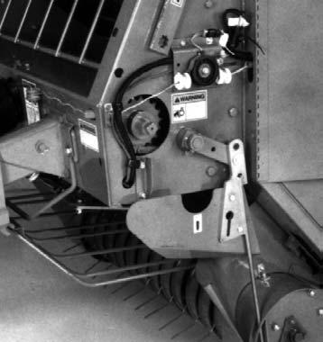
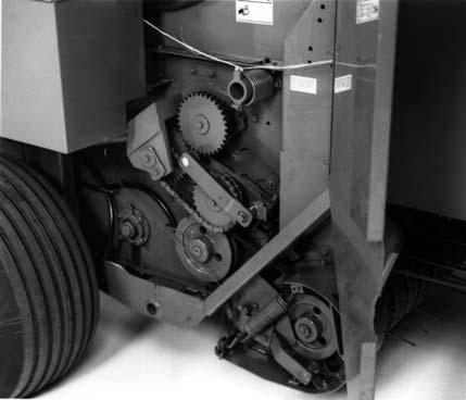
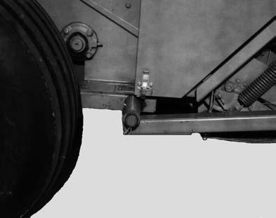
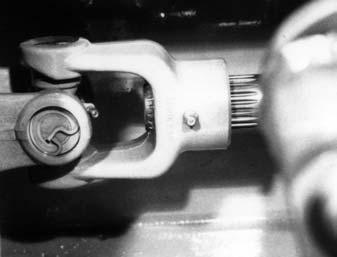
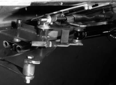
81 Chapter 8 Lubrication Front Master Printed in U.S.A /CP0600
82 Chapter 8 Lubrication The following is a duplicated listing of the Grease Fitting Locations provided for your convenience when viewing the locations in the photographs. Grease Fitting Locations Grease Every 10 hours (or Daily) 1. Telescoping Drive Crosses (3 Places) (can be either center of Cross or end of Cross) 2. Universal Jackshaft 3. Idler Arm Pivot (Right Side) 4. Lower 8 Roller Bearing Housing (1 each side) 5. Lower 16 Roller Bearing Housing (1 each side) (On right side, hidden beneath shield) 6. Packing Roller Arm Bearing (1 each side) 7. Packing Roller Arm Pivot (1 each side) 8. Bale Starter Pivot Bearing (1 each side) 9. Gate End Roller Bearing (1 each side) 10. Gate Latch Torsion Tube Pivot (1 each side) 11. Scraper Roller Bearing Housing (1 each side) Grease Every 50 hours (or Weekly) 12. Overrunning Clutch (Scraper Roll) 13. Pickup Drive Belt Idler Pivot 14. Twine Tie Pivots (2 Places) 15. Pickup Flotation Torsion Shaft Pivot (1 each side) 16. Telescoping Drive Tube 17. CV Joint Housing (2 Places) 18. Gate Cylinder Pivot (1 each side) 19. Gate Latch Bearing (1 each side) 20. PTO Overrunning Shear Device Grease Every 100 hours (or Monthly) 21. Gate Pivot Bushing (1 each side) 22. TDC Cylinder Idler Pivot (1 each side) 23. Optional Crowder Wheel Pivot (1 each side) /CP Printed in U.S.A.


83 Chapter 8 Lubrication Rear Master Printed in U.S.A /CP0600
84 CHAPTER 9 SERVICE WARNING BEFORE Servicing this unit, exercise the MANDATORY SAFETY SHUTDOWN PROCE- DURE (page 10). NOTE: The following information is referred to in both the Troubleshooting Guide and the Maintenance Schedule chapters of this manual. It should also be understood that all services covered in this chapter are Owner-Operator responsibilities. Where indicated, certain service routines should only be carried out by an authorized GEHL Dealer or GEHL Company representative. SEALED BALL BEARING REPLACEMENT (Fig. 99) 3. Press the Locking Collar against the Bearing wide inner ring and turn it, in the direction of Shaft rotation, until it tightly engages. Tighten the Collar further by tapping on a punch inserted in the drift pin hole. NOTE: Avoid damaging the Collar by overtightening it. 4. Last, tighten the Set Screw in the Locking Collar Sealed Ball Bearings are used on various Shafts around the unit. This type of Bearing is generally retained in place with a Self-locking Eccentric Collar. The Lock Collar has a counter bored recess, which is eccentric with the Collar bore. This eccentric recess engages or mates with an eccentric end of the Bearing inner ring, when the Bearing is assembled on the Shaft. The Bearing is engaged, on the inner ring cam, by the Collar. This assembly grips the Shaft tightly with a positive binding action that increases with use. The Collar Set Screw provides supplementary locking. 1 Bearing 2 Set Screw 3 Collar Cam 4 Wide Inner Cam Ring 5 Drift Pin Hole 6 Eccentric Self Locking Collar Fig A Bearing can be removed from the Shaft by loosening the Set Screw and tapping on a punch which is placed in the drift pin hole, to loosen the Collar. Install Bearings with self-locking Collars in the following manner: 1. Place the Bearing and Collar on the Shaft with the cam surfaces next to each other. Tighten the bolts on the Bearing Retainers. 2. Mate the cam of the Lock Collar with the cam of the Bearing inner ring. BALE SIZE INDICATOR CORD (AUTOMATIC & MANUAL TWINE WRAP MODELS ONLY)(Fig. 100) The Bale Size Indicator Cord links the Pointer above the Indicator Plate to the Belt Shuttle on top of the Baler. Pointer position, through appropriate Cord routing, changes with the position of the Shuttle which moves as the bale grows in size inside the Bale Chamber. If the 3/16 Cord wears out, a new Cord can be obtained and /CP Printed in U.S.A.
85 Chapter 9 Service routed as shown. For the RB1475, order part number or, for the RB1875, order part number WARNING NEVER use your hands to search for hydraulic fluid leaks. Escaping fluid under pressure can be invisible and penetrate your skin causing serious injury! If any fluid is injected into your skin, see a doctor at once! Injected fluid MUST be surgically removed by a doctor familiar with this type of injury or gangrene may result. PICKUP (Figs. 102, 103 & 104) 1 Indicator Cord 2 Pointer 3 Indicator Plate Fig. 100: Indicator Cord Routing GATE HYDRAULICS (Fig. 101) Refer to the Hydraulic Circuit Diagram provided for details on Gate Cylinder plumbing. 1 Right Gate Cylinder 2 Left Gate Cylinder 3 To Tractor Hydraulics Output 4 To Optional Chain Oiler 5 Gate Cylinder Lock Valve Fig Three Holes for 3/8 x 3/4 Cap Screws 2 Hole for 3/8 x 1-1/4 Grade 8 Cap Screws 3 Retainer 4 Reel 5 Cam Arm 6 Cam 7 Cam Follower (520175) 8 Cam Bolt (066490) 9 1/16 to 1/8 (1.6 to 3.2 mm) Fig. 102: Cam Follower Printed in U.S.A /CP0600
 away from the inside edge of the Cam Track as shown. 2.")
86 Chapter 9 Service The Pickup should be inspected on a routine basis every 100 hours of operation. The following inspections should be made: 1. The Cam Follower Bearings should be positioned from 3/16 to 5/16 (4.75 to 8 mm) away from the inside edge of the Cam Track as shown. 2. Depending on conditions, the Cam Followers will wear out and need to be replaced. When replacing, it is recommended that the Bolt (GEHL ) also be replaced. Apply Loctite 609 or equivalent and torque the Bolt to 75 ft-lb (104 N-m). NOTE: It is not necessary to remove the Pickup from the Baler to replace the Cam Follower Bearing. An access port is provided. See Fig. 103 for details. NOTE: NO lock washer is used with the Bolt. 3. To check for Cam wear and binding in the Cam, remove the V-Belt which drives the Pickup and turns the Drive over one complete revolution by hand. NOTE: Readjust any areas that are binding. 4. Inspect the (4 each side) Sintered-metal Bearings at points where the Bars pivot. Oil Seals are provided on each side of these Bearings. Also, BE SURE to check that the Tine Bar hardware is tightly secured. 5. Check for broken Pickup Tines. Best operation is only obtained after all broken Tines have been replaced. Pickup Tines can be ordered by GEHL number (for the double Tine) or (for the single Tine). The Pickup Drive Sheave has (2) set screw holes and the Driven Sheave has (2) set screw holes. The hole over the keyway contains two set screws, one screw to lock the other, similar to jam nuts. Install the appropriate Sheaves on their respective Shafts as shown. 1 TOTAL DENSITY CONTROL (TDC) SYSTEM 1 Cam Bearing Access Port Fig. 103 WARNING NEVER use your hands to search for hydraulic fluid leaks. Escaping fluid under pressure can be invisible and penetrate your skin causing serious injury! If any fluid is injected into your skin, see a doctor at once! Injected fluid MUST be surgically removed by a doctor familiar with this type of injury or gangrene may result. Reservoir Air Pressure (Fig. 105) 1 Drive Sheave 2 Two Set Screws 3 Keyway 4 Driven Sheave 5 Front of Pickup 6 Idler Fig. 104 The TDC system comes primed from the factory with a special grade of hydraulic oil capable of operating at lower ambient temperatures than normal hydraulic oils. If low temperatures and slow shuttle returns are not a problem, ATF (Dexron II) is an acceptable oil to use in the TDC system. The system is to be pressurized to 150 PSI (1050 kpa) by air pressure in the Reservoir. For normal operation, the Reservoir Pressure Gauge MUST /CP Printed in U.S.A.

87 Chapter 9 Service indicate a pressure reading of 140 to 150 PSI ( kpa). If the reading is NOT within this range, either add AIR or bleed off AIR, as necessary, using the Tank Inlet and Valve Stem at the top of the Reservoir. WARNING DO NOT pressurize the Reservoir to more than 150 PSIG (1050 kpa) when adding air and NEVER pressurize with anything other than AIR! Reservoir (Fig. 105) The Reservoir fluid level should be checked before each day of Baler operation (or at regular 10 hour intervals) using the Sight Tube located on the forward side of the Reservoir. Proper fluid level can be determined when both Density Cylinders are fully retracted. In this condition, the level of fluid in the Sight Tube should be slightly below the level mark Decal. NOTE: If the fluid level is below the bottom 1 (25 mm) level mark, add fluid BEFORE attempting to operate the Baler. Refer to the Adding Fluid to Reservoir topic below for proper refilling procedures WARNING DO NOT remove any hydraulic lines or fittings until you are sure that the system is depressurized and that there is no load on any hydraulic components. Failure to heed may result in personal injury Adding Fluid to Reservoir (Fig. 105) 8 1 Relief Valve & Adapter 2 Tank Inlet & Valve System 3 TDC Reservoir 4 Sight Tube 5 Valve Trip Mechanism 6 Trip Arm 7 Oil Level Mark 8 Density Cylinder 9 Trip Spacer 10 Adjustable Relief Valve 11 Reservoir Pressure Gauge 12 Density Cylinder Air Bleed Valve Fig. 105 NOTE: When operating this machine during times of extreme cold ambient temperatures and if a faster shuttle return speed is desired, use only oil supplied by Gehl in the TDC System. Refer to the Draining and Repriming System later in this Chapter for the proper draining procedure WARNING NEVER contaminate the reservoir fluid with any flammable liquid. ONLY use non-flammable cleaning solvents for cleaning components or containers used for storing, transporting or transferring the fluid. If the fluid should become contaminated with a flammable liquid, the resulting mixture, when combined with compressed air, can explode causing death or serious injury. To add fluid to the TDC System Reservoir, proceed as follows: 1. Make sure TDC cylinders are fully retracted (Baler empty and tailgate closed and latched). 2. Clean the top of the Reservoir to prevent any contamination during draining or refilling. 3. Fully depressurize the system by loosening or removing (and retaining) the Valve Stem from the Inlet at the top of the Reservoir. Printed in U.S.A /CP0600
88 Chapter 9 Service 4. Remove and retain the Relief Valve Adapter from the top of the Reservoir. 5. The TDC system comes primed from the factory with a special grade of hydraulic oil capable of operating at lower ambient temperatures than normal hydraulic oils. If low temperatures and slow shuttle returns are not a problem, ATF (Dexron II) is an acceptable oil to use in the TDC system. Add the necessary amount of fluid through the Relief Valve Adapter opening to bring the level in the Sight Tube in line with the lower level mark on the TDC Reservoir (both Density Cylinders MUST be fully retracted when using the lower level mark). 6. After the proper amount of fluid has been added, reinstall and secure Relief Valve Adapter (and Valve Stem, if removed) at top of the Reservoir. 7. Using AIR pressure ONLY, repressurize the system to PSI ( kpa). If the system has air in it (or gets air into it from opening a hydraulic line), it MUST be reprimed. Or, if the system requires complete draining (to change to a lighter or heavier fluid, for example), refer to the System Draining and Repriming Procedure for details. System Draining and Repriming Procedures (Fig. 105) 1. Make sure TDC cylinders are fully retracted (Baler empty and tailgate closed and latched). 2. Clean the top of the Reservoir to prevent any contamination during draining or refilling. 3. Fully depressurize the system by loosening or removing (and retaining) the Valve Stem from the Inlet at the top of the Reservoir. 4. Remove and retain the Hardware securing the Trip Spacer to the Trip Arm for the right side Density Cylinder and remove the Trip Spacer. This MUST be done to prevent accidental activation of the Valve Trip Mechanism. 5. Fully extend both Density Cylinders by pulling on the Belts at the back of the Baler (this will pull the Shuttles back and extend the Cylinders) and then block them in the extended position so they will NOT retract. 6. Check the fluid level in the Reservoir. With both Density Cylinders fully extended, the fluid level should be in line with or slightly above the upper level mark on the Reservoir. If fluid has to be added, go to Step 9. If the fluid is going to be drained and replaced, continue with Step 7. If repriming is all that is required, go to Step Place a 2 gallon or larger container near the right side Density Cylinder to catch the fluid during draining. Disconnect the TDC Reservoir Hydraulic Hose at the Manifold Disconnect and allow the fluid to drain into the container. IMPORTANT: Whenever service is performed on hydraulic components (valves, cylinders, hoses, etc.), care must be taken to prevent discharging fluid onto the ground. Catch and dispose of fluid per local waste disposal regulations. 8. After draining is completed, reconnect the Hydraulic Hose at the Manifold Disconnect. 9. Remove and retain the Relief Valve Adapter from the top of the Reservoir. 10. The TDC system comes primed from the factory with a special grade of hydraulic oil capable of operating at lower ambient temperatures than normal hydraulic oils. If low temperatures and slow shuttle returns are not a problem, ATF (Dexron II) is an acceptable oil to use in the TDC system. Add the necessary amount of fluid through the Relief Valve Adapter opening to bring the level in the Sight Tube in line with the upper level mark on the TDC Reservoir (both Density Cylinders MUST be fully extended when using the upper level mark). 11. After the proper amount of fluid has been added, reinstall and secure Relief Valve Adapter (and Valve Stem, if removed) at top of the Reservoir. 12. Check the Belts to MAKE SURE that they are NOT twisted and remove any blocking used to hold the Density Cylinders in the extended position. 13. Using AIR pressure ONLY, repressurize the system to PSI ( kpa). Repressurizing the Reservoir forces oil through the hydraulic lines and retracts the Density Cylinders. 14. Bleed any air that may have entered the Density Cylinders by carefully opening the Bleed Valve at the top of each Density Cylinder. NOTE: It may be necessary to repeat steps 3., 9., 10., 11., 12. and 13. several times in order to completely bleed the air from the Density Cylinders /CP Printed in U.S.A.
89 Chapter 9 Service 15. Reinstall the Trip Spacer and secure it to the Trip Arm. MAKE SURE that the Trip Spacer properly contacts the Valve Trip Mechanism before resuming baling. Pressure Relief Valve (Figs. 105 & 106) Faulty Valve Operation Malfunction of the Adjustable Pressure Relief Valve is suspected if one or more of the following conditions arise while baling: 1. If desired density bale can NOT be produced, contamination may be keeping the Relief Valve Poppet from seating properly. To test this: first, fully depressurize the system by loosening or removing (and retaining) the Valve Stem from the Inlet at the top of the Reservoir. Then, remove the Pipe Plug from the top of the Adjustable Relief Valve Manifold and in its place, install a 1000 PSI (7000 kpa) MINIMUM pressure gauge. Next, loosen the Locking Ring on the Adjustable Relief Valve (turn it counterclockwise) and then, gently turn the End Disc clockwise until it bottoms. Now, remove the Trip Spacer and rotate the Valve Trip Mechanism clockwise to its upper stop position. Make sure that there is sufficient fluid in the Reservoir and then open the Gate to extend the Density Cylinders. The indicated pressure on the pressure gauge (installed above) MUST be at least 500 PSI (3500 kpa), otherwise the Relief Valve Poppet is NOT seating properly. 2. If the Density Cylinders will NOT retract quickly, contamination may be blocking the Check Valve and preventing the hydraulic oil from flowing freely through the Valve. To check this, turn the Valve Trip Mechanism to its counterclockwise stop position when the Density Cylinders are extended. If the Cylinders quickly retract, the Check Valve is malfunctioning. 3. If excess power is required for baling or if frequent Belt failure is experienced, contamination may be blocking the Relief Valve Poppet, thereby preventing free flow of fluid through the Valve. To test this, use the same test procedures as for Step 1 above and if the gauge reading rises above 700 PSI (4900kPa), the Relief Valve may be blocked. If any or all of the above situations occur, the Pressure Relief Valve can be partially disassembled following details in the next topic. Relief Valve Removal & Replacement If the Adjustable Pressure Relief Valve is suspected of leaking or blockage, it can be partially disassembled in the following manner: WARNING DO NOT remove any hydraulic lines, fittings or components until you are sure that the system is depressurized and that there is no load on any hydraulic components. Failure to heed may result in personal injury. To fully depressurize the system, loosen or remove (and retain) the valve stem from the inlet at the top of the reservoir (see Ref. 2, Fig. 108). 1 Ring & Backup Washer 2 Area of Possible Contamination 3 Locking Ring 4 End Disc 5 O-Ring 6 Poppet Fig. 106: Adjustable Relief Valve Cartridge Printed in U.S.A /CP0600
90 Chapter 9 Service 1. MAKE SURE the system is depressurized. Also, MAKE SURE the Density Cylinders are fully retracted and there is NO bale in the machine. 2. Carefully disconnect the Reservoir-to-Manifold Hose at the Manifold Disconnect Coupler. 3. Remove and retain all but one of the four Manifold Bracket mounting bolts so the Manifold assembly can be swung clockwise as far as the Hose connections will allow and temporarily secured (with the remaining screw). The Manifold should be rotated to avoid excessive fluid loss. IMPORTANT: Whenever service is performed on hydraulic components (valves, cylinders, hoses, etc.), care must be taken to prevent discharging fluid onto the ground. Catch and dispose of fluid per local waste disposal regulations. WARNING BE SURE to wear a face and eye protection shield or goggles and position yourself so that your face is away from the valve to prevent contact with the escaping fluid. 4. Carefully loosen the Adjustable Relief Valve and bleed off pressure from the system. 5. After pressure has been removed, the Valve can be removed from the Manifold and the opening should be plugged to prevent contamination. 6. Inspect the Cartridge for a leaky or blocked Poppet. Force the Poppet on the front end of the Cartridge backward and, using a clean punch, rotate the Poppet to dislodge any contamination. 7. After step 5 has been performed, check the two outside O-rings for damage and then replace the Cartridge into the Manifold. 8. With the Cartridge replaced, reattach the Manifold assembly into its original mounting position and secure it. 9. Carefully and properly reconnect Quick coupler. 10. Check the Reservoir fluid level and pressurize to PSIG ( kpa) before attempting to resume operation. NOTE: If the Baler fails to operate properly after the above procedures have been carried out, contact your dealer for further directives. To order replacement Valve Cartridge, specify GEHL part # (1475) and (1875). To repair Cartridge specify GEHL part # for Seal Kit. Replace Check Valve with part # TRANSMISSION IMPORTANT: Internal Transmission component repairs and replacements should only be attempted by (or under the direction of) an authorized GEHL equipment dealer. To remove Transmission for service, proceed as follows: 1. Remove Windguard Assembly. 2. Remove Twine Tie System (5 bolts, 1 electrical connection on Manual Tie, 2 electrical connections on Auto-Electric models). 3. Release Drive Chain tension, break the Drive Chain and loosen the Bearing attaching hardware. 4. Loosen 4 flangette mounting bolts on cross shaft. 5. Slide cross shaft off of transmission output shaft. 6. Remove the (4) fasteners securing the Transmission Housing to the Crosstube. 7. Carefully remove the Transmission from the unit. After service is performed, replace the Transmission in reverse order of removal. Then, replace the oil until it comes out the Inspection Hole or reaches the full mark on the Dipstick. The Transmission requires 3 U.S. pints of SAE 80W90EP Gear Lube. Replace and readjust the Drive Chain. TWINE KNIFE When resharpening the Twine Knife, only sharpen the beveled edge. Remove the (2) bolts to take the Knife off the Cut-off Arm. BELTS WARNING BEFORE Servicing this unit, exercise the MANDATORY SAFETY SHUTDOWN PROCE- DURE (page 10) /CP Printed in U.S.A.

91 Chapter 9 Service Activating Shuttle Locks (Fig. 107) WARNING BEFORE servicing the belts, BE SURE to release the tension on the belts with the shuttle locks. NEVER have the PTO engaged while the shuttle locks are engaged. ALWAYS engage BOTH locks to make sure that belt tension is completely locked out. To use the Shuttle Locks, first open the Gate. Then, carefully climb up onto Twineboxes, remove the Hairpin Cotterpins and swing the Locks over. Reinstall the Hairpin Cotterpins, carefully climb down and then slowly close the Gate. 1 1 Shuttle Lock Engaged (One Each Side) Fig Relief Valve & Adapter 2 Valve Stem 3 Sight Tube 4 Reservoir 5 Trip Arm 6 Trip Spacer Assembly 7 Right Density Cylinder 8 Valve Trip Mechanism 9 Manifold 10 Relief Valve Cartridge (070633) 11 Pressure Gauge 12 To Left Density Cylinder 13 Magnet (Inside Reservoir) Fig. 108: Total Density Control (TDC) System Printed in U.S.A /CP0600
92 Chapter 9 Service Belt Tension (Fig. 108) If the Belts do NOT return or otherwise are NOT returning fast enough after ejecting a bale, check out the following items in the order listed to troubleshoot and correct the problem. 1. Check the Gauge pressure for the Reservoir while the Baler is empty. If the pressure reads less than PSI ( kpa), add air to bring the pressure up to PSI ( kpa). If the pressure drops again after a short time, there is most likely a leak at one of the fitting connections. To find the leak, apply a soapy water solution to the fittings and watch for air bubbles to form. As necessary, tighten the fitting connection or replace the fitting. Be careful NOT to overtighten the fittings and damage the threads. 2. Check the Reservoir hydraulic fluid level. With the Cylinders fully retracted, the fluid should be between 1 (25 mm) from the bottom of the Reservoir to just below the Oil Level Decal mark. Refer to TDC System topic in this chapter under Reservoir subtopic for additional information. 3. Check the plumbing arrangement and compare your machine to the routing shown in the TDC Hydraulic Circuit Diagram provided. 4. Check the operation of the Pressure Relief Valve following details under the Pressure Relief Valve subtopic contained within the TDC System information in this chapter. 5. Check for sticking Density Cylinders. Release the Reservoir air pressure. Remove the Trip Spacer from the Trip Arm and then fully extend both Density Cylinders by pulling the Belts at the back of the Baler. Slowly pressurize the Reservoir to 25 PSI (75 kpa). Cylinders should retract completely and smoothly. Cause of Belt Failure When a Belt fails, it will usually occur in the area of Lacing Hooks and will be caused by one or more of the following: 1. Bale improperly formed. 2. Lacing wire worn or broken. 3. Belt not properly laced. 4. Belts not tracking properly. 5. Build-up on Roller(s) or Scraper. 6. Baling when conditions are too wet. Splicing and Re lacing (Fig. 109) Belts are laced with #4-1/2HT Clipper Lacing Hooks and 3/32 diameter Nylon-coated Cable. These materials and a 6 (152 mm) Vice Lacer can be obtained as service accessories; see the Optional Features & Accessories chapter of this manual. To relace a Belt, the following additional items will be needed: small square, ball point pen, sharp knife, long-nose pliers, slip-joint pliers and a vice. To re lace a Belt, follow the procedure below: 1. Open the Rear Gate, engage the Shuttle Locks and completely close Gate to remove Belt tension. Then remove the Belt to be re laced. 2. Mark the Belt with the small square and ball point pen just behind the old hooks or 5/8 (16 mm) from the end of the Belt. Carefully cut the Belt with a sharp knife. Check the squareness from both sides after cutting. Clip the corners as shown. NOTE: Relace both ends of a pulled lacing joint. By limiting the amount of Belt cut to 5/8 (16 mm) on each end, a Belt can be re laced twice before alternative action is required; see Maintaining Belt Length section for details. 3. Install #4-1/2HT Hooks with the Vice Lacer. Make sure the ends of the Hooks protrude through the Belt and are clinched over. 4. Make sure outside Hooks are on the leading Belt end. Install relaced Belt in the Baler. 5. Cut an 8 (203 mm) long piece of Nylon-coated Cable. Bend a 3/4 (19 mm) loop in one end of the Cable. Install Cable in splice positioning loop as shown. 6. Restore Belt tension by opening the Rear Gate and returning the Shuttle Locks to storage. 7. Using the long-nose pliers, trim and bend the remaining end of the Cable into a loop with a minimum of 3/4 (19 mm) engagement into the lacing. NOTE: To keep the belt splice in good operating condition, it is recommended that the Lacing Cables be replaced every 500 bales /CP Printed in U.S.A.
93 Chapter 9 Service 1 Trailing End 2 Leading End 3 Outside Lacing Hook 4 Direction of Belt Travel 5 Lacing Pin (cable) Fig. 109 Maintaining Belt Length The length of the Belts should be maintained within 2-1/2 (63.5 mm). This 2-1/2 (63.5 mm) difference between Belt lengths can be achieved in either of two ways: a. by switching Belts around to different positions, or b. by using Dutchman Splices. a) Switching Belts The lacing on the outside Belts is more likely to fail before the inside Belt lacing. Outside Belts that have already been relaced can be switched towards the center of the Baler where less stress will be placed on the lacing. NOTE: This practice of switching is the recommended procedure for purposes of expense and repair time reduction. b) Dutchman Splice The original or matching Belt length can be restored by using a Dutchman Splice on a Belt which has been shortened excessively by repeated re lacings, a diagonal cut or a tear. NOTE: It is important to keep an accurate record of re lacing for each Belt so that a Belt can be re laced twice before the Belt is switched or a Dutchman is necessary. Dutchman Splice Installation NOTE: The Dutchman Splice MUST be at least 12 (305 mm) in Belt length for ample lacing separation. If Lacings are staged too close together, the Belt Lacings will fail quicker. BE SURE to use the longest Dutchman available as the piece that will be cut off. The long Belt will (hopefully) be good enough for more than 1 foot and then itself be usable as a Dutchman. Refer to the Optional Features & Accessories chapter for Dutchmans available. RB1475 Belt (Fig. 110) Perform the following steps to restore a short or torn RB1475 Belt: 1. Cut one end off the long Belt as close to the damaged area as possible and without including the damaged area. Relace this end. 2. Determine what overall length of Belt has to be developed (Belt length only, NOT including Lacing). To determine the overall length, consider the following: a. A new Belt is 469 ( mm) long. b. Belts should be maintained within 2-1/2 (63.5 mm) of each other. c. Check your records as the Belt may already have been reduced in length due to previous Lacing failures. 3. After the overall length required has been determined, subtract the following: a. Dutchman belt length b. Extra gap necessary of 1/2 (13 mm) 4. After the above measurements and calculations are made, cut the long Belt to the appropriate length determined and re lace it. 5. Install the Cable Lacing Pin in one joint, reassemble the Belt into the Baler and install the other Cable Lacing Pin. Example Given a 36 (915 mm) Dutchman and a full length Belt that is badly torn and now needs to be re laced. To what length should the damaged Belt be cut. Refer to Fig. 110 and follow the calculation below. Printed in U.S.A /CP0600
94 Chapter 9 Service Solution Belt Length Desired? (This may be less than 469 if all other Belts have already been cut off) 469 Minus Dutchman Belt Length -36 Minus Additional Belt Gap -1/2 (Due to additional Lacing) 432-1/2 Therefore, Belt MUST be cut to a length of 432-1/2 A + B + 1/2 (13 mm) = Belt Length Desired ( mm) 2 New Belt 3 Belt Length Desired 4 Tear 5 1/2 (13 mm) 6 3/8 (9.5 mm) /4 (895 mm) 8 1/4 (6 mm) /2 ( mm) Fig. 110: RB1475 Belt Repair Detail RB1875 Belt (Fig. 111) Perform the following steps to restore a short or torn RB1875 Belt: 1. Cut one end off of the long Belt as close to the damaged area as possible and without including the damaged area. Re lace this end. 2. Determine what overall length of Belt has to be developed (Belt length only, NOT including Lacing). To determine the overall length, consider the following: a. A new Belt is 552 ( mm) long. b. Belts should be maintained within 2-1/2 (63.5 mm) of each other. c. Check your records as the Belt may already have been reduced in length due to previous Lacing failures. 3. After the overall length required has been determined, subtract the following: a. Dutchman belt length b. Extra gap necessary of 1/2 (13 mm) 4. After the above measurements and calculations are made, cut the long Belt to the appropriate length determined and re lace it. 5. Install the Cable Lacing Pin in one joint, reassemble the Belt into the Baler and install the other Cable Lacing Pin. Example Given a 36 (915 mm) Dutchman and a full length Belt which is badly torn and now needs to be relaced. To what length should the damaged Belt be cut. Refer to Fig. 111 and follow the calculation below. Solution Belt Length Desired? (This may be less than 552 if all other Belts have already been cut off) 552 Minus Dutchman Belt Length? -36 Minus Additional Belt Gap? -1/2 (Due to additional Lacing) 515-1/2 Therefore, Belt MUST be cut to a length of 515-1/ /CP Printed in U.S.A.
95 Chapter 9 Service Check the Baler Tire pressure after every 50 hours of operation. Tires should be inflated to the 40 PSI (280 kpa). Wheel Lug Nut torque should be checked after every 50 hours of operation and tightened to 90 ft-lb (124 Nm) torque. A + B + 1/2 (13 mm) = Belt Length Desired /4 ( mm) 2 New Belt 3 Belt Length Desired 4 Tear 5 1/2 (13 mm) 6 3/8 (9.5 mm) /4 (895 mm) 8 1/4 (6 mm) /2 ( mm) Fig. 111: RB1875 Belt Repair Detail WHEELS & TIRES NOTE: Our Company does NOT sell replacement Tires. In addition, Tire mounting, repair and replacements should ONLY be attempted by a qualified tire manufacturer s representative or by properly trained personnel following the tire manufacturer s instructions. If you do not have such instructions, contact your tire dealer or our Company. WARNING Inflating or servicing tires can be dangerous. Whenever possible, trained personnel should be called to service and/or mount tires. In addition, DO NOT place your fingers on the tire bead or rim during inflation; serious injury or amputation could result. In any event, to avoid possible death or serious injury, follow the safety precautions below: BE SURE the rim is clean and free of rust. Lubricate both the tire beads and rim flanges with a soap solution. DO NOT use oil or grease. Use a clip-on tire chuck with a remote hose and gauge, which allows you to stand clear of the tire while inflating it. NEVER inflate beyond 35 PSI (240 kpa) to seat the beads. If the beads have not seated by the time the pressure reaches 35 PSI, deflate the assembly, reposition the tire on the rim, relubricate both parts and reinflate it. Inflation pressure beyond 35 PSI with unseated beads may break the bead or rim with explosive force sufficient to cause death or serious injury. After seating the beads, adjust the inflation pressure to the recommended operating pressure listed. DO NOT weld, braze, or otherwise attempt to repair and use a damaged rim. Printed in U.S.A /CP0600

 2 Knife Shield Fig. 112 2.")
96 Chapter 9 Service QUICK WRAP SERVICE Knife Removal and Installation (Figs. 112 & 113) 1. Begin by fully extending the Electric Actuator to rotate the Knife Holder away from the Knife Cutoff position. Then, unplug the Actuator to guarantee that the Knife can NOT be accidentally rotated Knives are very sharp. WARNING 4. Take special notice of the position of the Knives and Knife edges. 5. Detach the bolts and nuts and remove the Knives from the Knife Holder. 6. Sharpen or replace the Knives. 7. Reinstall the Knives on top of the Knife Holder with the beveled cutting edge facing down. 8. Reinstall the Knife Shield and tightly secure the attaching hardware before resuming operation Shield Attachment Bolt, Plain Washer & Lock Washer (1 each of 4) 2 Knife Shield Fig Remove the Knife Shield by detaching the (4) mounting fasteners. 3. Rotate the Knife Holder rearward for access to the mounting hardware. 1 Knife Holder 2 Knife (1 of 2) 3 Knife Secured to Holder with (4 each) 5/16 x 1 Cap Screws, Lock Washers and Hexagon Nuts. Fig /CP Printed in U.S.A.
97 Chapter 9 Service Notes Printed in U.S.A /CP0600
98 CHAPTER 10 PREPARING FOR FIELD OPERATION PREPARING THE MATERIAL Material to be baled should be clean and dry. Wet material will cause overloading in the Baler resulting in high Side Sheet resistance, wrapping on the Rollers and high Belt tension. In addition to baling problems, wet material when baled will have a tendency to spoil easier as well as be more prone to spontaneous combustion. Hay being prepared for round baling should be windrowed into a 45 or 24 (1143 or 610 mm) windrow for the RB1475 or, 61 or 36 (1549 or 914 mm) windrow for the RB1875 Baler. Corn stalks should be severed from their roots. Corn stalks, straw and other brittle materials should be raked into a full-width windrow, since these materials tend to break-up and deteriorate due to Side Sheet friction. In addition, the wider windrow will reduce crop loss or trash build-up. NOTE: Improper windrow widths result in barrel-shaped bales because of material overlap in the center of the bale. Narrow windrow widths will require a weaving path across the windrow to assure even crop distribution as the bale is formed. TRACTOR REQUIREMENTS & HITCH CONNECTIONS (Figs. 115 & 116) Tractor The Round Baler MUST be operated by a tractor with the following: 1. A minimum power output of 50 hp (37 kw) (RB1475) and 60 hp (45 kw)(rb1875) for level ground or 70 hp (52 kw)(rb1475) and 75 hp (56 kw)(rb1875) for hilly terrain or high density bales. 2. Having NON-tricycle type front wheels. 3. Having a minimum rear wheel inside dimension 45 (RB1475) or 61 (RB1875). 4. Equipped with a PTO which runs at 540 RPM with a standard 1-3/8 6-tooth spline (1000 RPM optional conversion is available). 5. Equipped with at least one set of double acting hydraulic outputs to operate Gate Cylinders. 6. Having standard PTO and hitch dimensions conforming to ASAE Standard S203, as shown. Figure 115 shows one of the two possible mounting positions for tractors with drawbars having 13 to 17 (330 to 432 mm) high ground clearance. Figure 116 shows one of the two possible mounting positions for tractors with drawbars having a ground clearance greater than 17 (432 mm) high. WARNING NEVER connect a 1000 RPM tractor to a baler equipped for a 540 RPM PTO drive. WARNING Because dry material is being processed, the tractor should also be equipped with a spark arrestor muffler, if the tractor emits sparks. IMPORTANT: If this unit is connected to a tractor equipped with a Hammer Strap style drawbar, the Hammer Strap parts shown in dashed lines MUST be removed to prevent damage to the unit Driveline. See Fig. 114 for details. 1 1 Hammer Strap Hitch Parts to be Removed Fig /CP Printed in U.S.A.
99 Chapter 10 Preparing For Field Operation 1 Tractor PTO Shaft* /2 (394 mm) for 540 Operation (17, 432 mm, 1000 RPM)(Measured from retaining groove in tractor PTO to center of Hitch Bolt) 3 6 to 12 (150 to 300 mm)* 4 13 to 17 (330 to 432 mm) From Ground 5 Locking Hitch Bolt (Provided) *Tractor MUST comply with ASAE Standard S203 Drawbar Connection When hooking the Baler to the tractor drawbar, BE SURE to use the Bolt, Nut and Hairpin Cotterpin provided. To prevent the bolt from becoming an obstacle to hay movement, insert the bolt from the bottom side of the tongue. Install the Hairpin Cotterpin after the Nut is secured. The proper Baler-tractor hook-up will NOT only allow maximum ground clearance but will also insure that the Baler will NOT become detached from the tractor. DRAWBAR FLAP (Fig. 117) If the Baler Drawbar is catching and bunching up the windrow below the Hitch, order and install a Drawbar Flap ( ) to help eliminate the problem. Fig. 115: Drawbar Hitchplate in Low Mounting Position (For tractors with 13 to 17 (330 to 432 mm) drawbar ground clearance 1 1 Drawbar Flap ( ) Fig. 117 PTO CONNECTION (Figs ) WARNING 1 Tractor PTO Shaft* /2 (394 mm) for 540 Operation (17, 432 mm, 1000 RPM)(Measured from retaining groove in tractor PTO to center of Hitch Bolt) 3 6 to 12 (150 to 300 mm)* 4 17 to 21 (432 to 535 mm) From Ground 5 Locking Hitch Bolt (Provided) *Tractor MUST comply with ASAE Standard S203 Fig. 116: Drawbar Hitchplate in High Mounting Position (Tractors with greater than 17 (432 mm) drawbar ground clearance DO NOT start the tractor until the locking device is positively engaged to hold the telescoping drive couplings onto the tractor pto shaft and baler transmission input shaft. Also, BE SURE that the drive shafts rotate freely inside the drive shield tubes. The Baler is equipped with a Constant Velocity Telescoping PTO Drive Shaft. This constant velocity capability, while cornering, results in a smooth, quiet running Drive Line, without power fluctuation. Printed in U.S.A /CP0600

100 Chapter 10 Preparing For Field Operation NOTE: Whether in operation or NOT, the Maximum Joint angle MUST NOT exceed 80. Any angle, greater than 80, WILL result in damage to the Joint. In addition, for continuous operation, the maximum Joint angle should be limited to 35. Wide-angle Constant Velocity Joints are NOT designed for use as angled-gearboxes. Any continuous operation, at angles greater than 35, will result in shortening Joint life. HYDRAULIC CONNECTIONS (Fig. 119) The Hoses for the Hydraulic Gate Cylinders are equipped with Pioneer ASAE S366.1 (SAE J1036, ISO 5675) quick-disconnect couplers. The Baler is delivered already primed with Type F Automatic Transmission Fluid (ATF) in the Gate Cylinder control hydraulic system. This should be changed if this is incompatible with your tractor hydraulic fluid. BE CAREFUL when handling the Hoses and fittings to insure that they are kept free of dirt and contamination to avoid damage to the Baler and/or tractor hydraulic system. NOTE: The Baler comes with the Rear Gate Cylinder system filled with Hydraulic Transmission Fluid. MAKE SURE this fluid is compatible with your tractor s hydraulic system BEFORE connecting to the tractor. If the fluid is NOT compatible, the system will have to be drained and refilled with the fluid used in your tractor. 1 A 35 (Maximum) in Continuous Operation & 80 (Maximum) at Any Time Fig. 118: PTO Constant Velocity Drive Shaft Joint 2 1 Hydraulic Disconnects (Customer Provided) 2 CV Joint Connected to Tractor PTO Shaft Fig /CP Printed in U.S.A.
 To thread the Baler with twine, proceed as follows: NOTE: Use the following twine routing procedure from each Twinebox through the Twine Tubes in the Baler Frame. 1. Place up to three balls of twine in the Twinebox.")
. On each side of the Baler, pull the end of twine from the center of the first ball and out through the hole in the side of the Twinebox.")
101 Chapter 10 Preparing For Field Operation TWINE ROUTING (Figs. 120 thru 124) To thread the Baler with twine, proceed as follows: NOTE: Use the following twine routing procedure from each Twinebox through the Twine Tubes in the Baler Frame. 1. Place up to three balls of twine in the Twinebox. If continuous feeding is desired, route the twine end through the Guide above the twine ball on the Twinebox Cover, tie the twine ends together (always tie the outside twine end of the first ball to the inside twine end of the next ball for continuous feeding). On each side of the Baler, pull the end of twine from the center of the first ball and out through the hole in the side of the Twinebox. 2 1 NOTE: The characteristics of the wrapping materials used to wrap bales varies significantly. Therefore, the way in which the twine is routed around the Twine Wheels (or through the Rope Guides on Manual Tie Models) is important. To achieve optimum placement of the wrapping material on the bale. The plastic material should be wrapped around the Twine Wheels 1-1/2 times. The sisal style twine works best with a 1/2 wrap around the Twine Wheel. However, if the Twine Wheel appears to be slipping, 1-1/2 wraps around the Twine Wheel should be considered. NOTE: The Twine Keeper is to be adjusted so the Tab of the Keeper rests on the Twine Guide while the outside corners of the Twine Keeper are flush with the outside edges of the Twine Wheels. The Twine Keeper is to be centered between the flanges of the Twine Wheel Twine Routed Through Guide in Cover 2 Twine Exiting Three-bale Twinebox 3 Twine Routed to and through Twine Tube in Front Frame Fig Feed the twine through the Twine Tube in the Front Frame, through the Rope Guide (Manual Control models) or Twine Sensor (Auto-Electric models) on the Frame, through the Twine Tube on the corner of the Hitch. 1 Twine Spring resting on Guide 2 Twine Wheel 3 Twine Guide Fig. 121: Twine Sensor (Automatic Bale Control Model) Printed in U.S.A /CP0600


102 Chapter 10 Preparing For Field Operation 1 1 Least Tension 2 Medium Tension 3 Maximum Tension Fig. 122: Automatic & Manual Twine Wrap Models 3. On RB1475 Model Balers, proceed routing the twine through the two Rope Guides on the front center of the Hitch and into one of the two Tubes on the Twine Arm. On RB1875 Model Balers, proceed routing the twine through the two upper Rope Guides on the front of the Hitch and into the one Rope Guide on the lower front of the Hitch. Continue into one of the two Tubes on the Twine Arm. 4. After the twine is through the Twine Arm, pull some twine from the Twine Arm to make sure it is dispensing freely and NOT hanging up. Cut off any excess twine which is extending from the Twine Arm more than 12 (305 mm) Twine from Twine Sensor 2 Twine to Twine Arm Fig. 124: Twine Routing on RB1875 Baler (Automatic Bale Control Model) NOTE: After the first bale has been tied, the twine (extending from the Twine Arm) will be held by the Clamp Jaws, after cutoff. The Clamp Jaws should provide a 20 (508 mm) tail of twine for starting to wrap the next bale. START-UP 2 WARNING BE SURE all bystanders are away from the baler, all tools and other objects have been removed from the baler and the windrow is clear of all obstacles BEFORE proceeding. In addition, BE SURE that the PTO shafts turn freely inside their shield tubes before starting the tractor. After the Baler is properly hooked up, start the tractor and run the PTO at a slow tractor RPM. Raise and lower the Rear Gate a few times to purge the hydraulic system of air and to make sure the Rear Gate opens and closes freely. 1 Twine Exiting Twine Tube in Front Frame 2 Twine Routed through Twine Sensor on Frame 3 Twine Routed into Guide Tube on Hitch Assy. 4 Twine Routed into Rope Guide to Twine Arm Fig. 123: Twine Routing on RB1475 Baler (Automatic Bale Control Model) /CP Printed in U.S.A.
 emblem. The Baler is also equipped with Red Reflector Strips on the rear corners of both Twineboxes.")
103 CHAPTER 11 TRANSPORTING SMV EMBLEM & REFLECTORS (Fig. 125) GEHL Company complies with all laws for safety when transporting slow-moving vehicles on public highways. The Baler is equipped with a Bracket for mounting a Slow Moving Vehicle (SMV) emblem. The Baler is also equipped with Red Reflector Strips on the rear corners of both Twineboxes. NOTE: The SMV emblem MUST be purchased locally. When the Baler is equipped with the Quick Wrap option, a SMV Decal is already attached to the back of the Quick Wrap. See Decal chapter for details Chain is sufficiently slack to allow turns and movements of either the tractor or the farm implement, without placing tension on chain. 2. Chain is of sufficient strength to hold the decoupled implement (and its load) and tow it to the shoulder. WARNING ALWAYS follow state and local regulations regarding use of a safety chain and transport lights when towing farm equipment on public highways. ONLY a safety chain (NOT an elastic or nylon/plastic tow strap) should be used to retain the connection between the towing and towed machine, in the event of separation of the primary attaching system. BE SURE to check with local law enforcement agencies for your own particular regulations. Unless otherwise prohibited, use a Slow-Moving Vehicle (SMV) emblem. 1 Transport Lights 2 Red Reflector Strip (Back of each Twinebox) 3 SMV Emblem Mounting Bracket Fig. 125 Because of the variations in safety laws for different states and localities, it may be necessary to change the Emblem Bracket location. Your local GEHL dealer can assist you in making the location change. SAFETY CHAIN & TRANSPORT LIGHTING (Figs. 125 & 126) As required or when desired, the Baler can be equipped with a Safety Chain for travel on public highways. Refer to the Optional Features & Accessories chapter for ordering information. The Safety Chain should be attached to the tractor and Baler as shown. When attached in this manner, the safety chain should have the following characteristics: 5 1 CV Stand in Storage Position 2 Locking Hitchbolt 3 Drawbar Clevis (Provided) 4 Chain Secured Around Tractor Frame Member 5 Safety Chain Attached Around Baler Frame Fig Printed in U.S.A /CP0600
104 Chapter 11 Transporting The RB1475 and RB1875 Round Balers are equipped with Transport Lights as standard equipment. A cord with a standard 7-pin connector to connect to the tractor is also provided. If your tractor is not equipped with the proper receptacle, see your tractor dealer for details. PICKUP (Fig. 127) Whether the Baler is equipped with the optional Hydraulic Lift Kit or not, BE SURE to raise the Pickup to the transport position with the Hand Crank provided anytime the Baler is being transported. The Pickup is raised by turning the Hand Crank in a clockwise direction and lowered by turning the Hand Crank in a counterclockwise direction. IMPORTANT: The Hand Crank settings act as the lower limit stop for the Hydraulic Lift Kit. BE SURE to reset this setting when resuming baling. 1 1 Pickup Lift Hand Crank Fig. 127: Baler With Pickup in Transport Position /CP Printed in U.S.A.
105 CHAPTER 12 STORAGE The following items are recommended for off-season storage of the Baler: 1. Remove all crop material and debris from behind the Sprockets, Sheaves, ends of the Rollers, Pickup... etc. 2. Grease all Fittings and make sure the Telescoping PTO Drive is completely greased. Repack the Wheel Bearings. Also, apply a light coat of grease to the Twine Knife. 3. Release tension on the Belts by locking out the Belt Shuttle. 4. Release tension from the V-belt which drives the Pickup. 5. Hydraulic Cylinder should be fully retracted and exposed Cylinder Rods should be coated with grease. 6. Apply motor oil to all Roller Chains, Telescoping Drive Shields and Guard Door Hinges. 7. Store the unit inside a shed, if possible, or cover the top half of the unit to protect the Belts, if stored outside. 8. Reorder and replace any required parts so that the Baler will be ready to operate at the start of the next baling season. 9. Cover and protect all exposed electrical connectors from dirt and corrosion. 10. Store Control Boxes in a protected dry area out of the weather. NOTE: Before starting up next season, go over the Checklists, chapter 3 in the front of this manual. PROTECTION OF UNPAINTED SURFACES Apply a rust preventative oil or grease to the following unpainted surfaces: All Roller Chains and Sprockets The Front PTO Drive Yoke and PTO Shaft Inside Side Sheets where paint is worn off Printed in U.S.A /CP0600
106 CHAPTER 13 TROUBLESHOOTING NOTE: This Troubleshooting guide presents problems, causes and suggested remedies beyond the extent of loose, worn or missing parts and it was developed with the understanding that the machine is in otherwise good operating condition. Refer to the index at the back of this manual for Chapter and Topic page references. BE SURE to exercise the MANDATORY SAFETY SHUTDOWN PROCEDURE (page 10), BEFORE making any adjustments or repairs. BALE APPEARANCE PROBLEM CAUSE REMEDY Bale density is greater in the center than on the ends (bale is barrel-shaped). Improper placement of material along edge of bale. Adjustable Relief Valve pressure is set too low. BALE DENSITY Rerake material into a proper width windrow or drive Baler in a weaving fashion. Increase Relief Valve pressure. Low Bale Density. Bale fails to rotate or rotates sporadically. Adjustable Relief Valve pressure is set too low. Low Reservoir pressure. Trip Spacer on Trip Arm is not engaging the Valve Trip Mechanism. Poppet in adjustable Relief Valve not seating properly or, 3/8 diameter Poppet is grooved. Air in the hydraulic lines or fluid level too low in Reservoir. BALE FILLING & BELTS Faulty Scraper Roller Overrunning Clutch Sprocket assembly. Material has too high of a moisture content. Pressure Relief setting too low. Low pressure in Reservoir. Increase Relief Valve pressure. Increase air pressure to between 140 to 150 PSI (980 to 1050 kpa). Adjust so that they are in line. Remove, inspect and clean Relief Valve Cartridge per instructions in Service chapter. Repair with part # Seal Kit. Re-prime system. Refill with correct oil. Lubricate Clutch. Check with wrench to see if clutch is free and overrunning in a clockwise direction. Stop baling and wait for material to dry out. Increase Relief pressure setting. Increase AIR to between 140 to 150 PSI (980 to 1050 kpa) /CP Printed in U.S.A.
107 Chapter 13 Troubleshooting BALE FILLING & BELTS (cont.) PROBLEM CAUSE REMEDY Belts getting under Bale Starter Fingers when closing Gate. Belt Lacing Hooks tearing out frequently. Belts are making squealing noise. Belts traveling to the side (excessively). Bale Starter sticking in Up Position. Low Reservoir pressure. Extremely cold conditions. TDC oil too thick for cold conditions. Bale improperly formed. Lacing Pin worn. Belt improperly laced. Belt NOT tracking properly. Build-up on Scraper or Rollers. Conditions too wet. Hooks improperly installed. Adjustable Relief Valve pressure too high for crop conditions. Baler is being run empty for too long a period of time. Gate End Roller improperly adjusted. Shuttle returning too slow. Belts rubbing together in rear. Lacing is NOT square to Belt edge. Belt Shuttle NOT square. Belt length variation greater than 2-1/2 (64 mm). Belt Tracking Roller improperly adjusted. Lubricate all of the pivots on the Bale Starter assembly. Leave PTO running while closing Gate. Increase pressure to between 140 to 150 PSI (980 to 1050 kpa). When ejecting bale, open Gate with PTO off, wait until Shuttle Stops, engage PTO and close and latch Gate. Use recommended oil for TDC system; see Lubrication chapter. Correctly form next bale; see Baling topic in Operation chapter. Replace the Lacing Pin. Correctly lace Belt. Correct Belt tracking; see Adjustments chapter. Remove build-up. Stop baling and wait for material to dry. Correct Hooks and clinch them over. Reduce Relief Valve pressure. Run Baler empty for a shorter time. Readjust End Roller; see Adjustments chapter. Increase Reservoir pressure to between 140 to 150 PSI (980 to 1050 kpa). Reduce bale diameter. Properly square edge and relace Belt. Readjust Belt Shuttle; see Adjustments chapter. Relace or replace Belts that are too short. Readjust Belt Tracking Roller; see Adjustments chapter. Printed in U.S.A /CP0600
108 Chapter 13 Troubleshooting BALE FILLING & BELTS (cont.) PROBLEM CAUSE REMEDY Gate opens prematurely while bale is still being formed. Excessive amount of material peeling off the bale resulting in large trash build-up. Gate Cylinders are NOT fully retracted to activate Latch. Gate Latch improperly adjusted. Improper use of tractor hydraulics or closing the Gate with the hydraulics in the float position. Tractor has faulty hydraulics. Tractor has low GPM output. Improper baling speed. Adjustable Relief Valve pressure is too high. Fully retract Cylinders. If NOT possible, check tractor and Baler circuits. Readjust Latch; see Adjustments chapter. When closing the Gate, tractor hydraulics should go to the Relief Pressure to insure that Gate is latched. Refer to tractor manual for repair. Close Gate as quickly as possible to force Hooks to engage Pins. Reduce the PTO speed and increase the ground travel speed. Reduce Relief Valve pressure. Material wrapping around Rollers. Moisture content too high. Stop baling and wait for material to dry. Adjustable Relief Valve pressure is high. Scraper improperly adjusted. Excessive PTO speed causing material to peel off the bale. Reduce Relief Valve pressure. Readjust Scraper; see Adjustments chapter. Reduce the PTO speed. CROP RELATED PROBLEMS PROBLEM CAUSE REMEDY Difficulty encountered in baling corn stalks, cane, etc. Improper baling speed. Reduce the PTO speed and increase the ground travel speed. Improper material preparation. Rake windrow into a full 45 (1140 mm) (1475) or 61 (1550 mm) (1875) wide row. Improper clearance between Packing Roller and Lower Roller. Higher Belt Tension is applied too soon. Material will NOT feed under Packing Roller. Readjust clearance; see Adjustments chapter. Lower position of the Trip Spacer. Adjust Wheel Spindle positions to raise Baler so that Pickup can be carried lower. Install Packing Roller Lagging Kit and/or remove right hand and left hand Crop Deflectors /CP Printed in U.S.A.
109 Chapter 13 Troubleshooting CROP RELATED PROBLEMS (cont.) PROBLEM CAUSE REMEDY Difficulty getting bale to grow in light windrow. Material is deteriorating on bale ends. Too much time spent forming bale. Gate End Roller to 16 Lower Roller clearance too great. Rake light windrows together. Reduce clearance; see Adjustments chapter. Material kicking ahead of Pickup. Improper baling speed. Reduce the PTO speed and increase ground travel speed. Improper material preparation. Increase or decrease the windrow size, as necessary. Material wraps on Packing Roller. Bale Starter does NOT drop down. Lubricate all of the pivots on the Bale Starter assembly. Leave PTO running while closing Gate. Material has too high a moisture content. Stop baling and wait for material to dry. Pickup can NOT be adjusted high enough or low enough. Material NOT feeding between Packing Roller and 8 Lower Roller. FEEDING INTO BALER Axle height improperly set. Tractor drawbar height does NOT meet specifications. Packing Roller too slippery. Windguard set too high. Improper Packing Roller to Lower Roller clearance. If occurring while starting a bale. Pickup is being carried too high for heavy windrows. Readjust Axle height; see Adjustments chapter. Readjust the drawbar height in accordance with specified dimensions listed in the Preparing for Field Operation chapter of this manual. Install Packing Roller Lagging Kit. Reduce Windguard s upward travel. Readjust clearance; see Adjustments chapter. Feed crop evenly until bale has started to rotate. Adjust Wheel Spindle positions to raise Baler so that Pickup can be carried lower. Material passes through the Baler. Gate NOT closed and latched. Close and latch Gate. Gate End Roller to 16 Lower Roller clearance too great. Readjust clearance; see Adjustments chapter. Printed in U.S.A /CP0600
110 Chapter 13 Troubleshooting MISCELLANEOUS PROBLEMS PROBLEM CAUSE REMEDY Belts return too slow or fail to return. Reservoir pressure too low. Increase pressure to PSI ( kpa). Drive Chain heating. Pickup will NOT go into Transport position. Pickup kicks up corn stalks or other lightweight materials. Pickup is NOT completely cleaning material off the field. Faulty Check Valve on Density Cylinders. Oil level is too low in Reservoir. Defective or contaminated Relief Valve. Operating in extremely cold conditions. Lack of lubrication. Install Accessory Chain Oiler. Poor Chain alignment. Relief Valve pressure is too high for crop conditions. Material has too high a moisture content. Mechanism blocked by debris. Transport position improperly adjusted. PICKING UP MATERIAL Improper baling speed. Improper material preparation. Improper baling speed. Broken or missing Tines. Pickup set too high off the ground. Windrow s too wide or the material (such as straw) is falling to the sides of the Pickup. Replace or repair faulty Check Valve. Re-prime system. Remove, inspect and clean relief Valve per instructions in Service chapter. Fill Reservoir with recommended hydraulic oil (see Lubrication chapter) and set Reservoir pressure to PSI ( kpa). Refer to Lubrication chapter. Realign Sprockets. Decrease Relief Valve pressure. Stop baling and wait for material to dry. Remove debris from on top of either the Pickup Header or Pivot Links. Correctly adjust Pickup for transport. Reduce the PTO speed and increase ground travel speed. Increase the windrow size by combining windrows. Increase the PTO speed and reduce ground travel speed. Replace broken or missing Tines. Readjust Pickup to lower the setting or lower the Baler Axle. Obtain and install Crowder Wheels /CP Printed in U.S.A.
111 Chapter 13 Troubleshooting PICKING UP MATERIAL (cont.) PROBLEM CAUSE REMEDY Pickup NOT running or running at below full speed. Difficulty is encountered in starting the bale to rotate. Pickup set too low to the ground. Improper Drive Belt tension. Pickup mechanism jammed. Overfill Clutch mechanism activated. Overfill Clutch improperly adjusted. STARTING THE BALE RPM too high. Packing Roller too slippery. Material is NOT being fed in uniformly. Material is extremely dry and windrows are too small, making it impossible for a sufficient amount of material to get into the Bale Chamber quick enough to start the core rolling. Readjust Pickup to raise the setting or raise the Baler Axle. Readjust the tension; see Adjustments chapter. Clean out blockage. Wrap and eject bale and make smaller bale the next time. Readjust Clutch mechanism and linkage. Reduce the PTO RPM to 300 on 540 RPM Balers and 700 RPM on 1000 RPM Balers. Install Packing Roller Lagging Kit. Feed crop evenly until bale has started to rotate. Increase the windrow size by combining windrows. Use Shuttle Stops to provide slackened Belts during core formation. Material wraps on Packing Roller. Bale Starter does NOT drop down. Lubricate all of the pivots on the Bale Starter assembly. Leave PTO running while closing Gate. Material has too high a moisture content. Baling below 50% moisture when making balage. Stop baling and wait for material to dry. Bale at moisture levels between 50% and 70%. Twine falls off left edge of bale. WRAPPING & EJECTING BALE Twine Tube is being extended too far to the left. Twine improperly wrapped around the bale. Bale improperly formed. Adjust Twine Arm Stop. When starting to wrap the bale with Twine, place two wraps of Twine at the center of the bale to secure the Twine on the bale. Feed more material on the edges of the bale on the next bale formed; see Baling topic in Operation chapter. Printed in U.S.A /CP0600
112 Chapter 13 Troubleshooting WRAPPING & EJECTING BALE (cont.) Twine will NOT start into the bale. Twine not routed properly. Reroute. Twine will not be placed on the left side of the Baler. Twine will NOT cut. Insufficient amount of material is being fed in with twine. Twine tails not long enough Twine itself is excessively kinky; poorly made or wet. Twine prematurely slipping out of Clamp Jaws. Obstruction in path of Twine Arm. Feeding too much crop when starting twine. Clamp Jaws will NOT latch open properly. Clamp Jaw Spring tension is too tight. Twine Knife NOT sharp. Feed in more material. Adjust Clamp Jaw Rod. Change the type of twine. Deburr the edges of the Clamp Jaws, and/or increase the Spring tension on the Clamp Jaws. Remove obstruction. Reduce amount of crop. Twine Arm is NOT being extended far enough to the left side and/or Spring Slide Rod adjustment is too long. Readjust tension; see Adjustments chapter. Sharpen or replace Knife. Gate will NOT open. Gate Latch improperly adjusted. Readjust Gate Latch; see Adjustments chapter. Bale will NOT fall out of Baler when baling cornstalks or haylage. Twine breaks when bale hits ground. Improper hydraulics connections. Gate Cylinder seals bad. Tractor has faulty hydraulics. Bale Ramps stop bale from falling. Insufficient number of wraps for size of bale and type of Twine. Twine is being cut between 8 roller and Packing Roller. Check, repair or replace connections. Replace seals. Refer to tractor manual for repair. Remove Bale Ramps. Increase number of wraps or reduce the size of the next bale. Maintain clearance of 1/4 (6 mm) above rods /CP Printed in U.S.A.
113 Chapter 13 Troubleshooting AUTOMATIC TWINE WRAP SYSTEM TROUBLESHOOTING NOTE: This Troubleshooting guide presents problems, causes and suggested remedies beyond the extent of loose, worn or missing parts and it was developed with the understanding that the machine is in otherwise good operating condition. BE SURE to exercise the MANDATORY SAFETY SHUTDOWN PRO- CEDURE (see page 10) BEFORE making any adjustments or repairs. PROBLEM CAUSE REMEDY System will not power up at all. The word SET appears in the Control Box Digital Display while operating in the AUTO mode. The word tie is continuously displayed in the Control Box Digital Display while operating in the AUTO mode. Poor connection with Wiring Harness at tractor power source. Blown fuse in Baler power Harness. Twine Arm is not in park (home) position. Twine Arm Position (Channel 5) setting is too high. Insufficient power to the Control Box. Twine Arm is not in park (home) position. End Wrap Pause Switch is not adjusted properly. Check for poor connections or broken wires in Power Harness. Repair any bare or broken wires in Harness. Replace with 20 amp automotive type fuse. 1. Switch the Mode Switch to MANUAL. 2. Using the Actuator Switch, RETRACT the Twine Arm to the park position. 3. Switch the Mode Switch back to AUTO. Check Channel 5 on the Display. If the reading is above 5.0 for a model 1475 Baler: 1. Using the DECREASE Switch, change the setting to 5.0 or lower. 2. Switch the Mode Switch to MANUAL. 3. Using the EXTEND/RETRACT Switch, RETRACT the Twine Arm to the park position. 4. Switch the Mode Switch back to AUTO. If the reading is below 5.5, do Steps 2 through 4, only. If the problem continues, see your dealer. The system requires a minimum of 11 volts D.C. and 20 amps to operate. Check all power connections and power source. 1. Switch the Mode Switch to MANUAL 2. Using the EXTEND/RETRACT Key, RETRACT the Twine Arm to the park position. 3. Switch the Mode Switch back to AUTO. Refer to the End Wrap Pause Switch Adjustment topic in the Operator s Manual. Printed in U.S.A /CP0600
114 Chapter 13 Troubleshooting AUTOMATIC TWINE WRAP SYSTEM TROUBLESHOOTING (Cont.) PROBLEM CAUSE REMEDY The word tie is continuously displayed in the Control Box Digital Display while operating in the AUTO mode. (Continued) Tie system will not start automatically. Tailgate OPEN/CLOSED Indicators do not function on Digital Display. Tailgate OPEN GATE message continues to flash on Digital Display after a bale has been discharged. Faulty Harness. End Wrap Pause Switch is faulty. Mode Switch is set to MANUAL. Trip Magnet is not activating the Bale Size Switch. Bale Size Switch is faulty. The Magnet on the Tailgate Switch Assembly is not properly adjusted. Tailgate Switch is faulty. The Magnet on the Tailgate Switch Assembly is not properly adjusted. Tailgate Switch is faulty. Check for continuity in Harness. Check for faulty End Wrap Pause Switch; Switch must close as the Magnet passes by. Set Mode Switch Fig. 30, Ref. 1 to AUTO. As the bale grows to the desired size, the Trip Magnet MUST slide within 1/8 inch (3.2 mm) of the Bale Size Switch (3/16 3/8 inch ( mm) on Early Style Baler Control). If necessary, adjust Magnet to proper location in slot and make sure the Switch is mounted in the proper location. Refer to the Adjustments chapter. Check for faulty Bale Size Switch; Switch must close when the Magnet is near the Switch. Adjust the Magnet on the Tailgate Switch Assembly so that it passes within 3/32 inch (2.4 mm) from the Switch. Check for faulty Tailgate Switch; Switch must close as the Magnet passes by. Adjust the Magnet on the Tailgate Switch Assembly so that it passes within 3/32 inch (2.4 mm) from the Switch. Check for faulty Tailgate Switch; Switch must close as the Magnet passes by /CP Printed in U.S.A.
115 Chapter 13 Troubleshooting AUTOMATIC BALE CONTROL SYSTEM TROUBLESHOOTING NOTE: This Troubleshooting guide presents problems, causes and suggested remedies beyond the extent of loose, worn or missing parts and it was developed with the understanding that the machine is in otherwise good operating condition. BE SURE to exercise the MANDATORY SAFETY SHUTDOWN PRO- CEDURE (page 10), BEFORE making any adjustments or repairs. BALE WRAPPING IMPROPERLY PROBLEM CAUSE REMEDY Bale size is inconsistent. Cab Module display powers up for a few seconds and then shuts off. System will not power up at all. Bale size sensor is not adjusted correctly (Fig. 83) or Jam Nuts are loose. Friction Block not adjusted properly; too loose. Power is not reaching the Implement Module. Poor connection with Wiring Harness at tractor power source. Blown fuse in Baler power Harness. The air gap between the tip of the Bale Size Sensor to the Sprocket Tooth should be adjusted to 0.1 to 0.12 (2.5 to 3 mm). The Friction Block is to clamp on the sprocket Hub so as to create 3-4 in-lb ( Nm) of drag when rotated up and down between stops. The power cord between the tractor and the Baler is not properly connected. Repair broken wire or poor connection between tractor power source and Implement Module. Faulty Implement Module. See dealer. Check for poor connections or broken wires in Power Harness. Replace with 20 amp automotive type fuse. Check for and repair any bare or broken wires in Harness. Printed in U.S.A /CP0600
116 Chapter 13 Troubleshooting BALE WRAPPING IMPROPERLY (cont.) PROBLEM CAUSE REMEDY The system starts before bale has reached programmed bale size. Friction Block is not adjusted correctly. Spacer/Magnet Assembly (located above left TDC Cylinder and to the rear of the Shuttle Return Switch) is set too close to Switch. Note: This assembly acts as an overall protection and starts the tie system before the Pickup assembly declutches. Clamp/Magnet Assembly located above left TDC Cylinder is not moving away from Shuttle Return Switch when TDC Cylinder is extended. The Friction Block is to clamp on the Sprocket Hub so as to create 3-4 inlb ( Nm) of drag when rotated up and down between stops. Refer to the Shuttle Return Switch topic in the Adjustments Chapter. Clamp/Magnet Assembly is to be clamped on square tube and should require 4 lbs. (18 N) of force to slide on tube. Spacer/Magnet Assembly (located above the left TDC Cylinder to the rear of the Shuttle Return Switch) is not moving away from the Shuttle Return Switch. Shuttle Return Switch stuck in closed position. Wires in Harness related to Shuttle Return Switch are short circuited. Free the Spacer/Magnet Assembly from the Shuttle Return Switch. The Spacer/Magnet Assembly should travel back and forth with the square tube located above the TDC Cylinder. The back and forth movement occurs as the TDC Cylinder Rod extends and retracts. To check for a faulty Shuttle Return Switch, separate Harness at Connector near the Switch. Check Switch continuity (using an ohmmeter or equivalent) by placing the tester leads on each Terminal of the Leads coming from the Switch. Whenever the Magnet in the mating part comes close to the Switch, the Switch should close. As the Magnet moves away from the Switch, the Switch should open. Check Wiring Harness for bare wires. Separate Harness at Connector near Switch. With a volt/ ohmmeter check the voltage across the two Terminals in the Harness end of the Connector. When the Control System is on, the voltage should be 5 volts DC /CP Printed in U.S.A.
117 Chapter 13 Troubleshooting ERROR MESSAGE EXPLANATIONS One of the functions of the Tractor Module is to display the conditions of the Bale Wrap system, both in the stages of normal and proper operation and also in recognition of errors, failures and faults. Potential Error Message codes are listed in the beginning of this chapter. E 1 - Out of Twine/Only One Twine on Bale (Twine Tie System ONLY) Twine Arm Stops at Right Side End Wrap Pause Position Push ENTER to Silence Beeper NOTE: The following information is developed in consideration of the Wrap System known to be correctly set up, properly wired and interconnected and operated in the AUTOmatic mode. For whatever reason, if the Twine Wrap system twine runs out, an E1 error message will be given and the following action should be taken: Exercise the MANDATORY SAFETY SHUTDOWN PROCE- DURE & Power-down the Wrap Control System Eject Bale Wrapped with Only One Twine & Continue Baling, if Desired Check for Cause of Error See E1 Troubleshooting Guide Reconnect PTO & Hydraulic Hoses, Restart Tractor Engine & Power-up Wrap Control System Push CYCLE to Repeat Tie Cycle Push ENTER to Re-activate System Feed in Small Amount of Crop to Get Twine Started If Wrap Material Starts, Resume Normal Operation Refer to SAFETY chapter of Baler Operator s Manual for details. E1 Troubleshooting Guide 1. Check twine supply and replenish if required. 2. Check if twine is broken, hooked, or pinched. Repair twine break and check to see if twine is routed properly. 3. Check that twine did not come off Twine Wheels. Reinstall if required. Adjust Twine Keeper, if required. 4. If E1 error is displayed just as Twine Arm comes to Home Position: a. The End Wrap Pause Switch is not adjusted correctly. Need to advance the Cam/Pause Plate. See the End Wrap Pause Switch topic in the Adjustments Chapter. b. Faulty End Wrap Pause Switch. To check for a faulty Switch, separate Harness at Connector near the Switch. Check the Switch continuity (using an ohmmeter or equivalent) by placing the tester leads on each Terminal of the Leads coming from the Switch. Whenever the Magnet in the mating part comes close to the Switch, the Switch should close. As the Magnet moves away from the Switch, the Switch should open. c. Check Wiring Harness for breaks or loose connections. Separate Harness at Connector near Switch. With a volt/ohmmeter, check the voltage across the two Terminals in the Harness end of the Connector. When the Control System is on, the voltage should be 5 volts DC. Printed in U.S.A /CP0600
118 Chapter 13 Troubleshooting E 2 - Out of Netting (Quick Wrap System ONLY) For whatever reason, if the Quick Wrap system netting runs out, the Actuator will return HOME and an E2 error message will be given. The following action should be taken: Actuator returns to Home Position Push ENTER to Silence Beeper Push CYCLE two times to find out the % of netting used from roll. Exercise the MANDATORY SAFETY SHUTDOWN PROCEDURE & Power-down the Wrap Control System Check E2 Troubleshooting Guide Reconnect PTO & Hydraulic Hoses & restart tractor engine & Power-up Wrap Control System If new roll of netting is installed, reset % of Netting by pressing CYCLE two times; on second time, hold CYCLE for 5 seconds until 0 appears in display Push CYCLE to repeat Wrap Material feeding attempt Push ENTER to Re-activate System When netting starts, normal operation can be resumed Refer to SAFETY chapter of Baler Operator s Manual for details. As desired, attempt wrapping again or stop here and eject bale. E2 Troubleshooting Guide 1. Check net supply and refill if required. 2. Check for torn netting: a. Brake is too tight. See operator s manual for brake adjustment. b. Netting is not routed properly. Check for proper net routing. c. Net roll does not rotate freely in storage position. Remove obstruction. d. Check for other foreign objects that might cause the roll of netting to rotate hard or not at all. 3. Pinch Count Switch and Magnet not functioning properly (Quick Wrap Only). Check the Pinch Count Switch located on the right side of the rubber Pinch Roller on the Quick Wrap. To check for a faulty Switch, separate Harness at Connector near the Switch. Check the Switch continuity (using an ohmmeter or equivalent) by placing the tester leads on each Terminal of the Leads coming from the Switch. Whenever the Magnet in the mating part comes close to the Switch, the Switch should close. As the Magnet moves away from the Switch, the Switch should open. The air gap between the plastic collar and the switch should be 1/16 (1.6 mm). 4. Check Wiring Harness for breaks or loose connections. Separate Harness at Connector near Switch. With a volt/ohmmeter, check the voltage across the two Terminals in the Harness end of the Connector. When the Control System is on, the voltage should be 5 volts DC. 5. Replace any broken parts. Remove any obstacles and rethread the netting outlined in the procedure on the Decal provided on the Quick Wrap /CP Printed in U.S.A.
119 Chapter 13 Troubleshooting E 3 - Twine/Netting NOT Started The Circular CYCLE Light Will Continue to Flash for Approximately 15 Seconds OR Until Both Twines or the Netting Has Started Feeding on the Bale. If the Wrapping Material Does NOT Start and an E3 Error appears, the Actuator Will Return to the Home Position Push ENTER to Silence Beeper Exercise the MANDATORY SAFETY SHUTDOWN PROCEDURE & Power down the Wrap Control System CHECK E3 TROUBLESHOOTING GUIDE Reconnect PTO & Hydraulic Hoses & restart tractor engine & Power-up Wrap Control System For Twine Tie Systems only, the Tie System works best if the cycle is started with hay. Push CYCLE to repeat Wrap Material feeding attempt Push ENTER to confirm cycle command For Twine Tie System ONLY, feed in small amount of crop to try to get twine to start If Wrap Material starts, normal operation can be resumed Push ENTER to Silence Beeper If Wrap Material does NOT start, System will Time out & E3 Error will appear CHECK E3 TROUBLESHOOTING GUIDE Refer to SAFETY chapter of Baler Operator s Manual for details. As desired, attempt wrapping again or stop here and eject bale. Printed in U.S.A /CP0600
120 Chapter 13 Troubleshooting E3 Troubleshooting Guide NOTE: E3 only appears if both twines or the net fail to wrap on the bale. System will successfully wrap bale with only one twine. 1. Check for depletion of wrapping material. 2. Wrapping material not routed correctly from storage location to discharge location. Check manual for correct routing. 3. Twine tail(s) not long enough (twine only). Check operator s manual for correct twine jaw adjustment. 4. Net not starting (Quick Wrap Only). See Quick Wrap troubleshooting section. 5. Pinch Count Switch and Magnet not functioning properly (Quick Wrap Only). Check the Pinch Count Switch located on the right side of the rubber Pinch Roller on the Quick Wrap. To check for a faulty switch, separate Harness at Connector near the Switch. Check the Switch continuity (using an ohmmeter or equivalent) by placing the tester leads on each Terminal of the Leads coming from the Switch. Whenever the Magnet on the mating part comes close to the Switch, the Switch should close. As the Magnet moves away from the Switch, the Switch should open. The air gap between the plastic collar and the switch should be 1/16 (1.6 mm). 6. Check Wiring Harness for breaks or loose connections. Separate Harness at Connector near Switch. With a volt/ohmmeter, check the voltage across the two Terminals in the Harness end of the Connector. When the Control System is on, the voltage should be 5 volts DC. 7. Both twines visually appear to be started but E3 reoccurs: a. Check that the twine has not jumped off the Twine Wheel. b. Check for faulty Twine Wheel Switch. Spinning both the Right and Left Twine Wheels independently by hand, should cause an E7 to appear on the Cab Module Display. If E7 does not occur, check for faulty Switch or missing Magnet in Twine Wheel. To check for a faulty Switch, separate Harness at Connector near the Switch. Check the Switch continuity (using an ohmmeter or equivalent) by placing the tester leads on each Terminal of the Leads coming from the Switch. Whenever the Magnet on the mating part comes close to the Switch, the Switch should close. As the Magnet moves away from the Switch, the Switch should open. c. Check Wiring Harness for breaks or loose connections. Separate Harness at Connector near Switch. With a volt/ohmmeter, check the voltage across the two Terminals in the Harness end of the Connector. When the Control System is on, the voltage should be 5 volts DC. 8. Bad wiring harness or poor connection: if both steps 5 and 6 check out OK, check out circuit for bare or broken wires or a loose connection. 9. Quick Wrap only. Check for trash in the net knife area. Also check that the Knife Carrier is being rotated away from the cutoff position and driving the Sprague Clutch. See net wrap troubleshooting section /CP Printed in U.S.A.
121 Chapter 13 Troubleshooting E 5 - Twine Arm Obstruction (Twine Tie System ONLY) NOTE: Twine may or may NOT have started; Twine Arm may return HOME automatically depending on whether Arm was moving out from HOME or moving back to HOME. Push ENTER to Silence Beeper Manually return Twine Arm to Home Position On a Twine Tie system only, an E5 error message could potentially occur, due to an obstruction in the path of the Twine Arm. The following action should be taken: Exercise the MANDATORY SAFETY SHUTDOWN PROCEDURE & Power-down the Wrap Control System CHECK E5 TROUBLE- SHOOTING GUIDE Check that twine is in the Clamps Reconnect PTO & Hydraulic Hoses & restart tractor engine & Power-up Wrap Control System Push CYCLE to repeat Wrap Material feeding attempt Push ENTER to confirm cycle command Feed in small amount of crop to try to get twine to start If Wrap Material starts, normal operation can be resumed Refer to SAFETY chapter of Baler Operator s Manual for details. As desired, attempt wrapping again or stop here and eject bale. Printed in U.S.A /CP0600
122 Chapter 13 Troubleshooting E5 Troubleshooting Guide 1. Check for and remove any visible obstructions. 2. If windrows are very large, the Windguard can be forced into the path of the Twine Arm. Slow down ground speed when full bale signal is given to reduce the amount of crop going into the baler. 3. If E5 is displayed when the Twine Arm travels completely to the left side of the baler without pausing and then returns home: a. The End Wrap Pause Switch is closing too late. See manual for End Wrap Pause Switch adjustment. b. End Wrap Pause Switch is sticking open. To check for a faulty Switch, separate Harness at Connector near the Switch. Check the Switch continuity (using an ohmmeter or equivalent) by placing the tester leads on each Terminal of the Leads coming from the Switch. Whenever Magnet on the mating part comes close to the Switch, the Switch should close. As the Magnet moves away from the Switch, the Switch should open. c. Check Wiring Harness for breaks or loose connections. Separate Harness at Connector near Switch. With a volt/ohmmeter, check the voltage across the two Terminals in the Harness end of the Connector. When the Control System is on, the voltage should be 5 volts DC. d. The gap between the End Wrap Pause Switch and magnet is too great. The air gap should be 1/16 to 3/32 ( mm). e. Twine Arm Stop Bolt (Fig. 66), used for stalling Actuator when applying end wraps to left side of bale, is extended out too far. The Twine Arm Linkage is striking the Stop Bolt before allowing Twine Arm to pause at pause position. f. Reset the Control System by disconnecting power to the Implement Module. This can be done by disconnecting the Power Chord between the Baler and tractor or by removing and reinserting the Fuse in the Baler Power Harness. 4. If E5 is displayed when Twine Arm stalls at Home Position: a. The End Wrap Pause Switch is opening too late. See manual for End Wrap Pause Switch adjustment. b. Faulty End Wrap Pause Switch. To check for a faulty Switch, separate Harness at Connector near the Switch. Check the Switch continuity (using an ohmmeter or equivalent) by placing the tester leads on each Terminal of the Leads coming from the Switch. Whenever the Magnet on the mating part comes close to the Switch, the Switch should close. As the Magnet moves away from the Switch, the Switch should open. c. Check Wiring Harness for breaks or loose connections. Separate Harness at Connector near Switch. With a volt/ohmmeter, check the voltage across the two Terminals in the Harness end of the Connector. When the Control System is on, the voltage should be 5 volts DC. 5. If E5 is displayed when Twine Arm stalls or hits an obstruction while in the extending mode: a. The Twine Arm will automatically return to Home Position. b. Exercise the Safety Shutdown and remove obstruction. c. Cycle tie system again. NOTE: If Twine Arm encounters an obstruction between the pause position and the left side of the Baler, it will continue its normal wrapping operation. However, the left portion of the bale will not be wrapped. This is usually caused by crops being fed into the Baler too heavy while starting the twine. Slow down or stop ground speed when full bale signal is given. 6. If E5 is displayed when Twine Arm stalls while in retracting position: a. System switches to manual mode and Twine Arm remains where obstruction occurred. Operator may have to manually control the Twine Arm away from the obstruction. b. Remove obstruction. c. Return Twine Arm to Home Position /CP Printed in U.S.A.
123 Chapter 13 Troubleshooting E 6 - Shuttle NOT Returned If the Tailgate closes but the Shuttle does NOT return, the Wrap system will do a self-analysis and, after 7 seconds delay, an E6 error message will be given. The following action should be taken: Push ENTER to Silence Beeper To Clear E6 from Display, operate the tractor hydraulics to open the Baler Tailgate. Next, engage the PTO. Then, slowly close and Latch Tailgate. If the System beeps and the GO Arrow appears, normal operation can be resumed If GO Arrow does NOT appear, continue with next steps. Push ENTER to Silence Beeper Exercise the MANDATORY SAFETY SHUTDOWN PROCEDURE & Power-down the Wrap Control System Check E6 Troubleshooting Guide Reconnect PTO & Hydraulic Hoses & restart tractor engine & Power-up Wrap Control System To Clear E6 from Display, operate the tractor hydraulics to open the Baler Tailgate. Next, engage the PTO. Then, slowly close and latch the Tailgate. The System should beep, the GO Arrow should appear and normal operation can be resumed. Refer to SAFETY chapter of Baler Operator s Manual for details. E6 Troubleshooting Guide 1. Check for twisted belts, or belt hooked on bale ramps. 2. Shuttle hanging up or shuttle locks engaged. 3. Check TDC system for correct air pressure and oil level. See manual for correct settings. 4. Check shuttle return switch so that trash is not obstructing the trip magnet. 5. Check that Friction Block with Magnet is properly positioned against Shuttle Switch. 6. Check for faulty Shuttle Return Switch. To check for a faulty Switch, separate Harness at Connector near the Switch. Check the Switch continuity (using an ohmmeter or equivalent) by placing the tester leads on each Terminal of the Leads coming from the Switch. Whenever the Magnet in the mating part comes close to the Switch, the Switch should close. As the Magnet moves away from the Switch, the Switch should open. 7. Check Wiring Harness for breaks or loose connections. Separate Harness at Connector near Switch. With a volt/ohmmeter, check the voltage across the two Terminals in the Harness end of the Connector. When the Control System is on, the voltage should be 5 volts DC. 8. Control system was not powered down before interrupting electrical power to the Baler (ie. starting tractor). This is important if a partial bale is in the Baler. Printed in U.S.A /CP0600
124 Chapter 13 Troubleshooting E 7 - False Start for Wrap Material NOTE: This error message may occur at any time during normal baling. If the twine starts prior to the tie cycle, an E7 error message will be given. The following action should be taken: Shut Off PTO Push ENTER to Silence Beeper Exercise the MANDATORY SAFETY SHUTDOWN PROCEDURE & Power-down the Wrap Control System Inspect the System components making sure that the twine or netting is NOT wrapping on the Pickup, Rolls, Drive components or other areas. As necessary, remove any excess wrap material. For Twine Tie System ONLY, check that the twine is in the Clamps and check the Knife for frayed twine on the Knife Power-up Wrap Control System Reconnect PTO & Hydraulic Hoses & restart tractor engine Resume baling if error message does not reoccur Refer to SAFETY chapter of Baler Operator s Manual for details. As desired, resume baling or wrapping. E7 Troubleshooting Guide 1. Inspect twine jaws to see if they are loose and working freely. (Twine Only) 2. Be sure that twine is routed correctly /CP Printed in U.S.A.
125 Chapter 13 Troubleshooting E 8 - End Wrap Pause (EWP) Faulty or Misadjusted (Twine Tie System ONLY) NOTE: When this error message occurs, the Twine Arm will return Home automatically. On a Twine Tie system only, an E8 error message could potentially occur, due to the End Wrap Pause (EWP) Switch being out of adjustment or faulty. The following action should be taken: Twine Arm will return to Home Position Push ENTER to Silence Beeper Exercise the MANDATORY SAFETY SHUTDOWN PROCEDURE & Power-down the Wrap Control System Check E8 Troubleshooting Guide Detach and unplug the Screw Plug from the tractor harness to the Baler power cord. This is located at the rear of the tractor. This should reset the system parameters. Then, re-connect the Plug. Reconnect PTO & Hydraulic Hoses & restart tractor engine & Power-up Wrap Control System Press CYCLE Push ENTER to Re-activate System Feed in small amount of crop to get the twine to start. Then, resume normal baling. Refer to SAFETY chapter of Baler Operator s Manual for details. As desired, attempt wrapping again or stop here and eject bale. E8 Troubleshooting Guide 1. If the Twine Arm hits an obstruction and stalls prior to the closing of the End Wrap Pause, an E8 will be displayed. Remove the obstruction. 2. E8 is displayed when Twine Arm travels uninterrupted to the left side of the Baler. The Switch is not closing due to misadjustment or a faulty Switch. To check for a faulty Switch, separate Harness at Connector near the Switch. Check the Switch continuity (using an ohmmeter or equivalent) by placing the tester leads on each Terminal of the Leads coming from the Switch. Whenever the Magnet in the mating part comes close to the Switch, the Switch should close. As the Magnet moves away from the Switch, the Switch should open. 3. Check Wiring Harness for breaks or loose connections. Separate Harness at Connector near Switch. With a volt/ohmmeter, check the voltage across the two Terminals in the Harness end of the Connector. When the Control System is on, the voltage should be 5 volts DC. Printed in U.S.A /CP0600
126 Chapter 13 Troubleshooting E 9 - Twine NOT Cut off (Twine Tie System ONLY) On a Twine Tie system only, an E9 error message will occur when the twine does NOT cut off. When this occurs, the following action should be taken: Shut Off PTO Push ENTER to Silence Beeper Exercise the MANDATORY SAFETY SHUTDOWN PROCEDURE & Power-down the Wrap Control System If twine is NOT cut, inspect the Knife Clamps and Blade for frayed material, dull knife edge or improper clamp tension. Check if twine is in the twine clamp. If not, place in clamps. Reconnect PTO & Hydraulic Hoses & restart tractor engine & Power-up Wrap Control System Refer to SAFETY chapter of Baler Operator s Manual for details /CP Printed in U.S.A.
127 Chapter 13 Troubleshooting E 10 - Low Voltage/Low Amperage The E10 Error Message usually occurs when the actuators are put in motion because of the additional current draw. Exercise the MANDATORY SAFETY SHUTDOWN PROCEDURE & Powerdown the Wrap Control System Check for Cause of Error and Correct Problem See E10 Troubleshooting Guide Restart Tractor Engine and Power Up the Control System Push ENTER to Silence Beeper Press the MANUAL/AUTO Key to Switch to Manual Mode and then Press the ENTER Key Manually Wrap the Bale Eject the Bale, Close the Tailgate and Wait for the GO Arrow When GO Arrow Appears, Switch to the AUTO Mode Press the MANUAL/AUTO Key and then the ENTER Key E10 Troubleshooting Guide 1. Check for poor connection at power source. 2. Power harness for the control system is not connected to an adequate power source. Connect power harness directly to battery or power source that is capable of supplying 17 amps at 12 volts. 3. Using an intermediate harness or wiring between the power cord and the power source should be 10 gauge wiring or greater and capable of supplying 17 amps at 12 volts. If at all possible, an intermediate wiring harness should be avoided. 4. Check integrity of the tractor electrical system. If E10 appears while starting tractor engine, it may be an indication of battery weakening. Check water level in the batteries. Check wiring harness connections at power source for corrosion or poor connections. If problem persists, check charging system and battery strength. Printed in U.S.A /CP0600
128 Chapter 13 Troubleshooting QUICK WRAP (NET) SYSTEM TROUBLESHOOTING NOTE: This Troubleshooting guide presents problems, causes and suggested remedies beyond the extent of loose, worn or missing parts and it was developed with the understanding that the machine is in otherwise good operating condition. BE SURE to exercise the MANDATORY SAFETY SHUTDOWN PRO- CEDURE (page 10), BEFORE making any adjustments or repairs. BALE WRAPPING IMPROPERLY PROBLEM CAUSE REMEDY The desired number of wraps is NOT being obtained. Frequent bending of Feeder Fingers. Bale is NOT being wrapped uniformly. Tear in the wrap material on bale. The Drive Roller Switch is NOT operating correctly. The Drive Roller tension is incorrect. Netting NOT started on Drive Rollers. Tailgate Roller too close to Floor Roller. Feeder Fingers NOT adjusted properly. Trash accumulation. Foreign material or crop buildup on the Feeder Fingers. Belts NOT tracking correctly. Rewrap Bar NOT locked down. An incorrect number of wraps is being placed on the bale. Foreign material, crop or wrap material buildup on the Rollers or Belts. Netting NOT routed properly. The roll of Netting material is too narrow or of inadequate quality. Rough edges or burrs on Tailgate Roller. Burrs on the Feeder Fingers. Rubber Ramp Shield NOT covering Bale Ramps. Feeder Finger snagging Netting when bale rolls out of Baler. Check that Roller Switch closes when Magnet passes by. Readjust the Drive Roller tension. Start netting on Roller per instructions on Decal. Move Tailgate Roller back away from Floor Roller approximately 1-1/2 (37 mm) from Tailgate Roller to the rib of the Floor Roller. Readjust Feeder Finger positions with Baler empty and Gate against stops. Remove trash accumulated inside Bale Forming Belts before the bottom Tailgate Roller. Remove any buildup and readjust the Finger positions, as required. Readjust the Belt tension and/or tracking per the information in this Supplement. Lock Bar in DOWN position. Readjust the wrap control to obtain at least two wraps. Carefully and properly remove crop or wrap material from Rollers and/or readjust Feeder Belt tension, as required. Properly route Netting per instructions at the beginning of this Supplement. Contact your Gehl dealer. Use ONLY Gehl approved wrap material. File off rough edges. Remove the burrs with a file. Reposition or replace Ramp Shield. Open Tailgate quicker /CP Printed in U.S.A.
129 Chapter 13 Troubleshooting BALE WRAPPING IMPROPERLY (cont.) PROBLEM CAUSE REMEDY Tear in the wrap material on bale (cont.). The Knife retracts to the Cutoff position but does NOT cut the material. Netting follows Bale Forming Belts up the front of the Baler instead of wrapping Bale. Improperly adjusted or plugged Feeder Fingers. Belts NOT tracking properly. The Knife edge has become dull. Lacing Cables exposed. Blemish (cut or fray) in belt. BALE NOT WRAPPED Readjust Feeder Finger positions. Readjust Feeder Belt tracking or reinstall Feeder Fingers on left side of their mounting Tabs. Remove the Knife, sharpen it and replace it. Re-lace main Baler belts and replace any lacing hooks. Repair Belt. Add Net Stripping Kit, as described in Optional Features Chapter. PROBLEM CAUSE REMEDY Feeder Belts stop turning or slip. Feeder Belt tension too loose. Readjust Feeder Belt tension. Wrap material wraps around Drive Rollers. Wrap material not reaching Bale at Lower Tailgate Roller. Rear Net Guide too close to Rubber Drive Roller. Too much wrap material is being indexed into Net Chute when starting Net Roll. Pinch Rollers damaged. Sticky material on Rubber Drive Roller. Feeder Finger NOT properly adjusted. Trash accumulation. Readjust Guide Roller. Install the wrap material per the instructions on the Decal. BE SURE to avoid rotating the wrapping material Roll more than 1 revolution. NEVER cut the Rubber Roller with a knife when attempting to remove wrapped material. Smooth off damaged areas with a file; it may be necessary to replace the Rubber Roller. Clean the Roller. Readjust Feeder Finger positions. Remove trash accumulation inside Bale Forming Belts by bottom Tailgate Roller. Printed in U.S.A /CP0600
130 CHAPTER 14 SET-UP & ASSEMBLY The Baler is shipped with the following parts NOT attached to the Main unit: Wheels & Tires Bale Ramp Shields (Quick Wrap Models) Bale Ramps Tractor Controls and Control Cables Hose & Cable Support WHEELS & TIRES The Baler may be shipped from the factory without Wheels and Tires mounted. Install the Tires and Rims; torque the Wheel Nuts to 90 ft-lb (124 N-m). Inflate the Tires to 40 PSI (280 kpa). Refer to the Wheels & Tires topic at the end of the Service chapter for additional information. IMPLEMENT PTO Installation of the PTO is covered in the Preparing for Field Operation chapter. BALE RAMPS (Fig. 128) The Bale Ramps and mounting hardware are packed loose in the Twine Box. Install each of the (2) Bale Ramps to the Axle mounted Ramp Anchors securing each with (4) 1/2 x 1-1/4 Cap Screws, Lock Washers and Nuts. Several mounting positions are available to allow compensation for various crop and field conditions. BALE RAMP SHIELDS & BALE RAMPS (QUICK WRAP MODELS ONLY) (Fig. 128) The Bale Ramp Shields and mounting hardware are packed loose in the Twine Box. Installation is as follows: 1. Remove the (4) 1/2 x 5 Cap Screws and 1/2 Lock Nuts that secure the (2) Ramp Anchor Assemblies and retain. 2. Install a Ramp Shield to the back of each Ramp Anchor Assembly securing with the retained (4) 1/2 x 5 Cap Screws, 1/2 Lock Nuts and adding (4) 1/2 Flat Washers as shown in Fig Install each of the (2) Bale Ramps to the Axle mounted Ramp Anchors securing each with (2) 1/2 x 1-1/4 Cap Screws, Lock Washers and Nuts. Several mounting positions are available to allow compensation for various crop and field conditions. 4. Roll the Ramp Shields over the Ramps and secure each using a Hold Down Strap, (2) 1/2 x 1-1/4 Cap Screws, Lock Washers and Nuts. 1 Ramp (2) 2 Ramp Shield (2) 3 Hold Down Strap 4 1/2 x 5 Cap Screw (4) 5 1/2 Lock Nut (4) 6 Flat Washer (4) 7 1/2 x 1-1/4 Cap Screw (8) 8 Lock Washer (8) 9 Nut (8) Fig. 128 HOSE & CABLE SUPPORT Attach the Hose & Cable Support to the right front face of the Hitch securing with (2) 5/8 x 2 Cap Screws, (2) 5/8 Flat Washers and Lock Washers. MAKE SURE to place the Flat Washers under the heads of the Cap Screws. Route the Hydraulic Hoses, Transport Lighting Cable and Baler Control Cable through the loop on the Hose & Cable Support. NOTE: To ease assembly, manually extend the Twine Arm for additional clearance /CP Printed in U.S.A.
131 Chapter 14 Set-up & Assembly TWINE TIE SYSTEMS NOTE: The Twine Arm and Actuator comes fully assembled and mounted on the Baler from the factory. Manual Twine Wrap System (Fig. 129) Tractor Control Box Installation A Bracket is provided for attaching the Receptacle onto the tractor. The Bracket should be located on the rear of the tractor in a position which prevents the Cable from being caught by the PTO. Appropriate hardware and mounting brackets are provided for attaching the Control Box to a non-supportive member (such as the cab or a fender) on the tractor. BE SURE to locate the Control Box within convenient reach. Make the Red (+) 12-volt and White (-) 12-volt tractor battery/ground connections for powering the Control Box. A 20 amp Bus Bar connection is also acceptable. Any intermediate wire or harness must be AWG 10 gauge or heavier. Bale Counter Installation 1. Pop rivet the Bale Counter to the Counter Mounting Bracket using the Pop Rivets supplied. 2. Attach one end of the Extension Spring to the Bale Counter Arm closing the loop in the Spring to secure. 3. Mount the Counter Assembly to the TDC Valve Trip Mechanism using the existing hardware on the Baler (TDC Valve Trip Stop Bolt & TDC Valve Mounting Bolt). 4. Loosen the TDC Valve Trip Mounting Bolt. Attach the other end of the Extension Spring to the end of the Bolt facing the front of the Baler and secure. Baler Actuator Cable Installation 1. Remove Windguard to gain access to the Twine Arm Actuator. 2. Route Actuator Cable through Cable and Hose Support, along Hydraulic Hoses, through the Hitch Assembly and plugging into the Actuator. Secure the Cable with the Cable Ties provided. CAUTION DO NOT secure cable to any moving parts or pinch points. 3. Replace Windguard. 1 Manual Twine Control Box 2 Control Box Mounting Bracket 3 1/4 x 3/4 Cap Screw, Lock Washer & Nut 4 Control Box to Implement Receptacle 5 Receptacle Mounting Bracket 6 1/4 x 1 Cap Screw, Lock Washer & Nut 7 Implement Harness Fig. 129: Manual Twine Control Parts 8 Wire Ties 9 Bale Counter 10 Counter Extension Spring 11 Counter Mounting Bracket (slotted hole to bottom) 12 Pop Rivet 13 Front Plate of TDC Valve Trip Printed in U.S.A /CP0600
132 Chapter 14 Set-up & Assembly Automatic Twine Wrap System (Figs ) 1. Connect the Power Harness to an adequate power source that is capable of supplying a minimum of 20 Amps at 12 Volts. Connect the RED power lead to the (+) polarity of the power source and the BLACK power lead to the ( ) polarity (Ground). Tractor Control Box Installation NOTE: If the RED power lead is connected to the wrong polarity, the system will NOT respond. 2. Avoid using an intermediate harness or wiring means between the power source and the Power Harness supplied with your Gehl Baler. 3. An inline fuse holder is manufactured into the RED (+) positive lead of the Power Harness. The holder has a 20 Amp spade type automotive fuse inside. For replacement use an equivalent 20 Amp fuse. 4. Route the Power Harness in such a way as to be protected by its location, but so it does not interfere with any other tractor controls or moving parts. Route the female connector end of the Harness to the tractor and plug the connector into the bottom of the Control Box. Route the bracket and male connector assembly to the rear of the tractor. Mount the bracket securely to the back of the tractor in a location that will keep and hold the power cord in a safe operating position. Baler Shuttle Position/Bale Size Sensor Installation (See Fig. 130) 1. Mount the Shuttle Position/Bale Size Sensor on the two rear upper Tie Rods of the left TDC Cylinder securing with two 1/2 Hex Nuts. MAKE SURE to position the Sensor Assembly so the Sensor is facing down or towards the rear of the machine. 2. Remove the special Screw, Lock Washer and Flat Washers that retain the Sprocket Assembly at the top of the left TDC Cylinder. Place the Slide Mounting Plate over the exposed Pin and secure with the removed hardware deleting one of the Flat Washers. 3. Pre assemble the Slide, Strap, Magnet Assemblies, Magnet Nuts and Nylon Washers as shown. 4. Route the Slide Assembly through the Shuttle Position/Bale Size Sensor and secure the Assembly to the outside of the Plate on the top of the TDC Cylinder clevis with a 3/8 x 1 Cap Screw and 3/8 Nylon Insert Lock Nut. Adjust the Magnet Assembly in the Slide to determine bale size. Move the Magnet closer to the sensor for smaller bales and farther from the Sensor for larger bales /CP Printed in U.S.A.
133 Chapter 14 Set-up & Assembly 1 Tractor Power Harness 2 Baler Control Module 3 Magnetic Control Stand 4 Implement Harness 5 Wire Tie 6 Tailgate Sensor Assembly 7 Clamp (13/16 Dia.) 8 Magnet Assembly 9 Nylon Washer 10 Magnet Nut 11 3/8 Flat Washer 12 3/8 x 1 Cap screw 13 Strap 14 3/8 Nylon Insert Lock Nut 15 Slide 16 Plate 17 Shuttle Position/ Bale Size Sensor Assembly 18 1/2 Nut Fig. 130 Printed in U.S.A /CP0600
134 Chapter 14 Set-up & Assembly Baler Tailgate Sensor Installation (See Fig. 130) 1. Remove the Nut and Lock Washer from the two lower Gate Stop mounting Bolts on the left side of the Baler. 2. Mount the Tailgate Sensor Assembly as shown securing with the two lower Gate Stop mounting Bolts. The Assembly has Weld Nuts for the Bolts. 1 Wire Ties 2 Clamp, 1 Dia. (25 mm) 3 5/16 Flat Washer 4 5/16 Lock Nut 5 Pause Sensor Cam Fig Upper Actuator Arm Assembly 7 Twine Tie Frame Assembly 8 5/16 x 1 Cap Screw 9 End Wrap Pause Sensor Assembly /CP Printed in U.S.A.
135 Chapter 14 Set-up & Assembly Baler End Wrap Pause Sensor Installation (See Fig. 131) 1. Remove Windguard to gain access to the Twine Tie Assembly. 2. Install Pause Sensor Assembly on Twine Tie Frame as shown securing with (2) 5/16 x 1 Cap Screws, (4) 5/16 Flat Washers and (2) 5/16 Lock Nuts. NOTE: The Pause Sensor Cam MUST pass between Magnet and Sensor without touching the Magnet or Sensor. Baler Cable Installation (See Fig. 130) 1. Route Implement Cable through Cable and Hose Support, along Hydraulic Hoses, through the Hitch Assembly and connect the Actuator leg (white & yellow wires) of the Cable into the Actuator. Also connect the End Wrap Pause leg (brown & green wires) to the End Wrap Pause Sensor. 2. Continue routing the Implement Cable through the left side of the Hitch Assembly, along the Twine Tube and to the remaining Sensors. The Connector with the grey & green wires goes to the Gate Latch Sensor and the Connector with the blue & green wires goes to the Shuttle Position/ Bale Size Sensor. 3. Secure the Implement Harness with the Wire Ties & Clamps as shown. 4. Replace Windguard (+) 4 1 ( ) 1 To Tractor 12 volt D.C. Power System 4 Power Harness 2 Inline Fuse Holder 5 Connect to Mating Round Plug On Implement Harness 3 Connect to Mating Plug On Tractor Module Fig. 132: Power Harness Printed in U.S.A /CP0600
136 Chapter 14 Set-up & Assembly To Tractor Power Harness 2 To End of Wrap Pause Switch 3 To Twine Arm Actuator 4 To Shuttle Position Switch 5 To Gate Latch Switch Fig. 133: Implement Harness AUTOMATIC BALE CONTROL SYSTEM (Figs. 134, 135 & 136) Implement Module The Implement Module is factory installed on the left side of the Baler next to the TDC Cylinder. The Implement Module is: 1. A memory storage unit 2. The controller for the Tractor Module 3. A fully pre-programmed computer 4. The component from which the Wiring Harness extends Tractor Module The Tractor Module is part of a mounting and wiring package for the tractor. The Module and mounting and wiring package comprises: 1. A cooperating Microprocessor with the Implement Module 2. A Liquid Crystal Display (LCD) Indicator 3. Eight (8) Touch Keypads which are used singly or in pairs to perform specific functions 4. Magnetic base male Spade Mount and Bracket for placement on tractor fender or other metal cab member within convenient operator arm s reach NOTE: If NO convenient metal member exists, remove Spade Mount and secure with field-supplied standard hardware. Remove protective cover from LCD Display by starting at one corner of the display and peel off plastic cover. Power Harness 1. Connect the Power Harness to an adequate power source that is capable of supplying a minimum of 17 Amps at 12 Volts. The red power lead is to be connected to the (+) polarity of the power source, and the black power lead is to be connected to the ( ) polarity (Ground) 2. Avoid using an intermediate harness or wiring means between the power source and the Power Harness supplied with your Gehl Baler 3. An inline fuse holder is manufactured into the (+) positive lead of the Power Harness (See Item 2, /CP Printed in U.S.A.
137 Chapter 14 Set-up & Assembly Fig. 134). The holder should have a 20 Amp spade type automotive fuse inside. For replacement use an equivalent 20 Amp fuse. NOTE: Do NOT reverse wiring connections because system will NOT respond. 4. Route the Power Harness in such a way as to be protected by its location, but not in interference with any other tractor controls or moving parts. The rectangular connector with the four wires is to be routed to the operator s station and plugged into the back of the Tractor Module. The bracket with the round 6-pin connector is to be routed to the back of the tractor. The bracket should be mounted securely to the back of the tractor in a location that will keep and hold the power cord in a safe operating position (+) 4 1 ( ) 1 To Tractor 12 volt D.C. Power System 4 Power Harness 2 Inline Fuse Holder 5 Connect to Mating Round Plug On Harness Extension 3 Connect to Mating Plug On Tractor Module Fig. 134: Power Harness From Harness Extension 2 To Baler Fig. 135: Implement Harness Printed in U.S.A /CP0600
138 Chapter 14 Set-up & Assembly Fig. 136: Baler Harness /CP Printed in U.S.A.
139 Chapter 14 Set-up & Assembly Pin Identifications Plug Identifications Pin A1 A2 A3 B1 B2 B3 B4 C1 C2 D1 D2 D3 D4 G1 G2 H1 H2 J1 J2 J3 J4 K1 K2 Wire Description Ground Black Twine Actuator (Yellow) Net Actuator Ground (Gate Latch - Black) Ground Gate Latch & Pinch Roll Return (Black) Bale Size Sensor +V (Red) Bale Size Sensor, Signal (Orange) Ground (Black) Left Twine Sensor (White) NOT Used Right Twine Sensor (Green) Pinch Roll Count (Violet) Shuttle Return (Pink) NOT Used Gate Latch Switch (Gray) Ground, Shuttle Return (Black) Serial Communication A. (Blue) Bale Size Sensor, Ground (Black) Left Twine Sensor Return (Black) End Wrap Pause (Brown) Serial Communication B. (Yellow) +12 Volts D.C. (Red) Twine Actuator (Red) Pin B3 B4 J1 K1 A1 C2 D2 J2 G2 B1 J3 C1 D3 B2 H2 J4 K2 A2 K3 A3 D4 H1 Wire Description Bale Size Sensor +V (Red) Bale Size Sensor, Signal (Orange) Bale Size Sensor, Ground (Black) +12 Volts D.C. (Red) Ground Black Left Twine Sensor (White) Right Twine Sensor (Green) Left Twine Sensor Return (Black) Gate Latch Switch (Gray) Ground (Gate Latch - Black) End Wrap Pause (Brown) Ground (Black) Pinch Roll Count (Violet) Ground Gate Latch & Pinch Roll Return (Black) Serial Communication A. (Blue) Serial Communication B. (Yellow) Twine Actuator (Red) Twine Actuator (Yellow) Net Actuator (Red) Net Actuator Shuttle Return (Pink) Ground, Shuttle Return (Black) K3 Net Actuator (Red) Printed in U.S.A /CP0600
140 CHAPTER 15 OPTIONAL FEATURES & ACCESSORIES GENERAL INFORMATION The following Optional Features & Accessories are available for installation on a Baler to increase its capabilities. Set-up and assembly information for all Kits, except the Twine Tie Mechanisms, are provided in separate instructions packaged with each Kit of parts RPM CONVERSION KIT The 1000 RPM Conversion Kit (806698) will convert a standard 540 RPM RB1475 or RB1875 to 1000 RPM operation. The Kit includes a 1000 RPM Transmission, a tractor to implement PTO, 8 Shear Bolts, 2 Decals and an Instruction Sheet. BELT LACING KIT The Belt Lacing Kit (802700) contains a 6 (152.5 mm) wide Clipper Vice Lacer, (6) #4-1/2 Clipper Hook Cards and a 72 (1829 mm) long piece of Nylon-coated Stainless Steel Cable. The Kit is required when it is necessary to repair a Baler Bale Forming Belt. Refer to details in the Service chapter of this manual for using the Kit. BELT RE-LACING KIT The Belt Re-lacing Kit (073390) contains the same components as the Belt Lacing Kit (802700) above with the exception of the Clipper Vice Lacer. This Kit is available to replace the supplies furnished with the above Kit. BELT LACING CABLE The Belt Lacing Cable (094104) is a 7 (178 mm) long piece of Nylon-coated Stainless Steel Cable used for rethreading a Belt splice. Refer to the instructions in the Service chapter of this manual for using this Cable. A 6 (1.83 m) roll of Lacing Cable is also available by ordering part number Instructions are included. CROWDER WHEELS KIT The Crowder Wheels Kit (806492) is available for expanding the Pickup width of either model Baler to enable taking in a wider swath of material. The Kit contains (2) Crowder Wheels, Mounts and attaching hardware. Installation, operation and adjustment details are provided with the Kit of parts. PACKING ROLLER LAGGING KIT (Fig. 137) The Packing Roller Lagging Kit (068633) is available to improve feeding into the Baler in certain crop conditions. The Kit contains (2) Strips of Lagging (Belting), (36) Rivets and (4) Cover Strips. Installation details are provided with the package of parts. 1 Lagging Strips 2 Rivets (2 of 36) 3 Cover Strips (2 of 4) Fig. 137: Packing Roller Lagging Kit (Installed) PICKUP HYDRAULIC LIFT KIT The Pickup Hydraulic Lift Kit (806946) is available for remote height control of the Crop Pickup from the tractor. The Kit contains a Hydraulic Cylinder, hydraulic connections and mounting hardware. Installation details are provided with the Kit. SHEAR BOLTS On 540 RPM model Balers, replacement Grade L9, 1/4 x 1-1/2 Shear Bolts are available in packaged quantities of (8) per package by ordering part number On 1000 RPM model Balers, replacement Grade 5, 1/4 x 1-1/2 Shear Bolts are available in packaged quantities of (8) per package by ordering part number /CP Printed in U.S.A.
 prevents the netting from following the belts up the backside of the Baler.")
141 Chapter 15 Optional Features & Accessories CHEVRONED BELT DUTCHMAN KIT The Dutchman Kit (126230) contains (1) 36 long, 6 wide section of Chevron Belt, already laced and ready for splicing. Installation details are provided with the Kit. NET STRIPPER KIT The Net Stripper Kit ( & ) prevents the netting from following the belts up the backside of the Baler. CHAIN OILER KIT The Chain Oiler Kit (806491) provides automatic oiling of all Drive Chains as the Baler is used. Installation details are provided with the Kit. SAFETY CHAIN (Fig. 138) The recommended Safety Chain for use with these Balers can be obtained in Kit NOTE: If the Baler is to be transported on a public highway, a Safety Chain Kit should be obtained and installed following the details in the Transporting chapter. Fig. 138: Safety Chain (Installed) CONNECTOR KIT This Connector Kit repairs the male and female ends of the Connectors (2 wires) that join the ends of the Baler Harness with the Left and Right Twine Feed Sensors, End Wrap Pause Sensor, Pinch Roll Count Sensor (Net Wrap models only) and the Shuttle Return & Full Size Bale Sensor on the Automatic Bale Control models. The Kit also repairs the Connectors for the End Wrap Pause Sensor, Gate Latch Sensor & Full Size Bale Sensor on the Automatic Twine Wrap models. Installation details are provided with the Kit. CONNECTOR KIT This Connector Kit repairs the male and female ends of the Connectors (3 wires) that join the ends of the Baler Harness with the Bale Size Sensor. Installation details are provided with the Kit. CONNECTOR KIT This Connector Kit repairs the male and female ends of the Connector (2 wires, 18 AWG blue and yellow) that joins the ends of the Baler Harness with the Implement Harness. Installation details are provided with the Kit. CONNECTOR KIT This Kit repairs the 6 hole Connector to the Cab Module of the Auto Electric Tie System in the tractor Power Harness. Installation details are provided with the Kit. CONNECTOR KIT This Connector Kit repairs the male and female ends of the Connector (2 wires, 10 AWG red and black) that joins the ends of the Baler Harness with the Implement Harness. Installation details are provided with the Kit. CONNECTOR KIT This Kit repairs the Fuse Holder in the tractor Power Harness on both Automatic Bale Control and Manual Twine Wrap models. Installation details are provided with the Kit. CONNECTOR KIT This Connector Kit repairs the end of the Baler Harness (30 wire Connector) that plugs into the Implement Module. Installation details are provided with the Kit. Printed in U.S.A /CP0600
142 Chapter 15 Optional Features & Accessories CONTACT KIT This Kit repairs the Contacts in the Plugs that join the tractor Power Harness to the Implement Harness on both Automatic Bale Control and Manual Twine Wrap models. The Kit also repairs the Contacts in the Plugs that join the tractor Power Harness to the Baler Control on the Manual Twine Wrap models. Installation details are provided with the Kit. CONNECTOR KIT This Kit repairs the Plug (tractor half of Connector ONLY) that joins the tractor Power Harness to the Implement Harness on both Automatic Bale Control and Manual Twine Wrap models. The Kit also repairs the Plug in the Baler Control that plugs into the tractor Power Harness on Manual Twine Wrap models. Installation details are provided with the Kit. CONNECTOR KIT This Kit repairs the Plug (Baler half of Connector ONLY) that joins Implement Harness to the tractor Power Harness on both Automatic Bale Control and Manual Twine Wrap models. The Kit also repairs the Plug in the tractor Power Harness that plugs into the Baler Control on Manual Twine Wrap models. Installation details are provided with the Kit. TWINE SENSOR JUMPER HARNESS (AUTOMATIC BALE CONTOL ONLY) This Harness provides the necessary electrical connection to enable the Baler to be operated using just one string of twine on the Automatic Bale Control models. 2 MAGNET TWINE WHEEL (AUTOMATIC BALE CONTROL ONLY) The 2 magnet Twine Wheel will speed up the twine tieing cycle. A Wheel MUST be ordered for each side of the Baler /CP Printed in U.S.A.
143 GENERAL INFORMATION Decal Locations information is provided to assist in the proper selection and application of new decals, in the event the original decal(s) become(s) damaged or the machine is repainted. Refer to the listing for the illustration reference number, part number, description and quantity of each decal provided in the Kit. Refer to the appropriate illustration(s) for replacement location(s). NOTE: Refer to the SAFETY Chapter of the Operator s Manual for the specific information provided on all of the various Safety Decals furnished in the Decal Kit(s). To insure proper selection for correct replacement decal(s), compare all of the various close-up location photographs to your machine BEFORE starting to refinish the unit. Then, circle each pictured decal (applicable to your machine) while checking off its part number in the listing. After you have verified all the decals needed for replacement, set aside unneeded decals for disposal. NEW DECAL APPLICATION Surfaces MUST be free from dirt, dust, grease and other CHAPTER 16 DECAL LOCATIONS foreign material before applying the new decal. To apply a solid-formed decal, remove the smaller portion of the decal backing paper and apply this part of the exposed adhesive backing to the clean surface while maintaining proper position and alignment. Slowly peel off the other portion of the backing paper while applying hand pressure to smooth out the decal surface. CAUTION ALWAYS observe safety rules shown on decals. If decals become damaged, or if the unit is repainted, replace the decals. If repainting, BE SURE that ALL decals from the kit(s) which apply to your machine are affixed to your unit. PAINT NOTICE Use this list to order paint for refinishing: One Gal. AG Red One Qt. Light Grey (12 oz. Spray Cans) AG Red (12 oz. Spray Cans) Light Grey Printed in U.S.A /CP0600
144 Chapter 16 Decal Locations For a complete Decal Set, order Part Number for the RB1475 model Baler or for the RB1875 model Baler. The following Decals (as required) are included in the Sets: Ref. Part No. No. Description & Quantity Operating Instructions General Operating Instructions Shuttle Lock Position (2 Places) Jack Storage Position Jack Lifting Position Belt Tracking Adjustment (2 Places) Patent Red Reflector Strip (2 Places) DANGER - Rotating Drive Line Lubrication Symbol (16 Places) IMPORTANT - Store Manual Here WARNING - Owner s Responsibility & Read Manual WARNING - General Safety WARNING - Keep Door Closed (3 Places) WARNING - Rotating Wrench WARNING - Reservoir Contamination DANGER - Belt Entanglement DANGER - No Manual Feed (2 Places) WARNING RPM Operation ONLY WARNING - Rotating Drive Line GEHL 5 x 23-1/2 (Front) Colorbar 13-1/2 (1 on Each Side) ** Bale Size Indicator ( ) ** Bale Size Indicator ( ) ** Bale Size Indicator (1475)* Oil Level Indicator Reservoir Maintenance * TDC (1 on Each Side) High Moisture (Left Side)(1475 only) High Moisture (Right Side)(1475 only)* Tailgate Lock (After SN & SN ) Tailgate Lock (Before SN & SN ) DANGER - Moving Tailgate (2 Places) DANGER - Baler Entanglement (2 Places) GEHL (1 on Each Side) DANGER - PTO Shield (under Shield) * Not Shown ** Automatic & Manual Twine Wrap Models Only NOTE: Order Part Number for 10 ft roll of replacement Striping /CP Printed in U.S.A.


145 Chapter 16 Decal Locations Front Master Printed in U.S.A /CP0600
146 Chapter 16 Decal Locations NOTE: This following is a duplicated listing of the Decals from a previous page. It is provided for your convenience when selecting Decals from the second page of photographs. For a complete Decal Set, order Part Number for the RB1475 model Baler or for the RB1875 model Baler. The following Decals (as required) are included in the Sets: Ref. Part No. No. Description & Quantity Operating Instructions General Operating Instructions Shuttle Lock Position (2 Places) Jack Storage Position Jack Lifting Position Belt Tracking Adjustment (2 Places) Patent Red Reflector Strip (2 Places) DANGER - Rotating Drive Line Lubrication Symbol (16 Places) IMPORTANT - Store Manual Here WARNING - Owner s Responsibility & Read Manual WARNING - General Safety WARNING - Keep Door Closed (3 Places) WARNING - Rotating Wrench WARNING - Reservoir Contamination DANGER - Belt Entanglement DANGER - No Manual Feed (2 Places) WARNING RPM Operation ONLY WARNING - Rotating Drive Line GEHL 5 x 23-1/2 (Front) Colorbar 13-1/2 (1 on Each Side) ** Bale Size Indicator ( ) ** Bale Size Indicator ( ) ** Bale Size Indicator (1475)* Oil Level Indicator Reservoir Maintenance * TDC (1 on Each Side) High Moisture (Left Side)(1475 only) High Moisture (Right Side)(1475 only)* Tailgate Lock (After SN & SN ) Tailgate Lock (Before SN & SN ) DANGER - Moving Tailgate (2 Places) DANGER - Baler Entanglement (2 Places) GEHL (1 on Each Side) DANGER - PTO Shield (under Shield) * Not Shown ** Automatic & Manual Twine Wrap Models Only NOTE: Order Part Number for 10 ft roll of replacement Striping /CP Printed in U.S.A.


147 Chapter 16 Decal Locations Rear Master Printed in U.S.A /CP0600
80 Series. Variable Chamber. Round Balers
 80 Series Variable Chamber Form No. 909804 Revision B Round Balers 480 - Before SN800 580 - Before SN400 680 - Before SN7800 780 - Before SN7800 880 - Before SN500 OPERATOR S MANUAL GEHL NEW AGRICULTURAL
Impeller Disc Mower Conditioner
 252 Form No. 90987 Revision B Impeller Disc Mower Conditioner OPERATOR S MANUAL GEHL NEW AGRICULTURAL EQUIPMENT IMPELLER DISC MOWER CONDITIONER WARRANTY GEHL AGRICULTURE DIVISION of the GEHL COMPANY, hereinafter
R T SERIES ROTARY TILLER
 R T SERIES ROTARY TILLER Operating and Maintenance Manual TABLE OF CONTENTS 1. PRODUCT WARRANTY. 3 2. CHECKLIST Dealer s File Copy. 4 Customer s File Copy.. 5 3. INTRODUCTION 6 4. SPECIFICATIONS.. 7 5.
ROTARY RAKE OPERATOR'S MANUAL
 MODEL 1150 ROTARY RAKE OPERATOR'S MANUAL DO NOT OPERATE THIS EQUIPMENT UNTIL THIS MANUAL HAS BEEN READ AND UNDERSTOOD. Part Number: 17.00801C May 2005 Miller-St. Nazianz, Inc. P.O. Box 127 St. Nazianz,
610 BUSHEL MANURE SPREADER
 610 BUSHEL MANURE SPREADER RODA MANUFACTURING 1008 LOCUST ST. HULL, IA. 51239 Art s-way Manufacturing 712-439-2366 Co., Inc. Hwy 9 West - PO Box 288 WWW.RODAMFG.COM Armstrong, IA. 50514 U.S.A 2 INTRODUCTION
W & A 12 ROW TOP LEVELING STACKER LEVEL BANDER
 W & A 12 ROW TOP LEVELING STACKER LEVEL BANDER NO. 3640 OPERATOR S MANUAL TO THE OWNER: Congratulations on your purchase of a new W & A Top Leveling Stacker Level Bander. Your selection is an indication
MK AUGERS POWER SWING KIT ASSEMBLY & OPERATION MANUAL
 MK AUGERS POWER SWING KIT ASSEMBLY & OPERATION MANUAL Read this manual before using product. Failure to follow instructions and safety precautions can result in serious injury, death, or property damage.
LEWIS WINDROWER OWNER / OPERATOR MANUAL
 LEWIS WINDROWER OWNER / OPERATOR MANUAL MODEL # WR-1 WINDROWER Manufactured by: LEWIS BROTHERS MANUFACTURING, INC. Post Office Box 146 Baxley, GA 31513 Tel: (912) 367-4651 Fax: (912) 367-3958 2-21-14 1
Mulcher Operators Manual
 Mulcher Operators Manual Skid Pro Attachments PO Box 982 Alexandria, MN 56308 October 2015 1 2 Contents 1. Introduction And Warranty... 4 1.1 Introduction... 4 1.2 Warranty... 4 2. Component Identification...
3800 SERIES SINGLE HYDRAULIC LOCKING TOOLBAR
 3800 SERIES SINGLE HYDRAULIC LOCKING TOOLBAR 2565-774_REV_D 02/2018 OPERATOR S MANUAL PART IDENTIFICATION YETTER MANUFACTURING CO. FOUNDED 1930 Colchester, IL 62326-0358 Toll free: 800/447-5777 309/776-3222
Operator s/parts Manual
 Operator s/parts Manual 3-Point Solid Stand Drills Pull Hitch Package Manufacturing, Inc. P.O. Box 5060 Salina, Kansas 67402-5060! Read the operator s manual entirely. When you see this symbol, the subsequent
Wheel Horse. 36 Tiller. Model No & Up. Operator s Manual
 FORM NO. 8 9 Rev. A Wheel Horse 6 Tiller for Classic Garden Tractors Model No. 7970 690000 & Up Operator s Manual IMPORTANT: Read this manual carefully. It contains information about your safety and the
Form No Replaces. Finger Wheel Rake OPERATOR'S AND SERVICE PARTS MANUAL
 Form No. 903031 Replaces 902521 Finger Wheel Rake OPERATOR'S AND SERVICE PARTS MANUAL GEHL COMPANY New Agricultural Equipment Gehl Company (Incorporated), hereinafter referred to as GEHL, as manufacturer
FORAGE BOX MODEL 5300 REAR UNLOAD OPERATOR'S MANUAL DO NOT OPERATE THIS EQUIPMENT UNTIL THIS MANUAL HAS BEEN READ AND UNDERSTOOD.
 FORAGE BOX MODEL 5300 REAR UNLOAD OPERATOR'S MANUAL DO NOT OPERATE THIS EQUIPMENT UNTIL THIS MANUAL HAS BEEN READ AND UNDERSTOOD. Miller-St. Nazianz, Inc. Art s-way Manufacturing Co., Inc. P.O. Box 127
Wheel Horse. 44 Snowthrower. for 5xi Lawn and Garden Tractors. Model No & Up. Operator s Manual
 FORM NO. 8 Rev A Wheel Horse Snowthrower for 5xi Lawn and Garden Tractors Model No. 7966 890050 & Up Operator s Manual IMPORTANT: Read this manual, and your tractor manual, carefully. They contain information
CRUSTBUSTER OWNER / OPERATOR MANUAL
 CRUSTBUSTER OWNER / OPERATOR MANUAL MODEL # CB-1 CRUSTBUSTER Manufactured by: LEWIS BROTHERS MANUFACTURING, INC. Post Office Box 146 Baxley, GA 31513 Tel: (912) 367-4651 Fax: (912) 367-3958 5-2-17 1 INTRODUCTION
Operator Manual. Includes operating, adjustment, maintenance, technical, repair parts, and safety instructions for the 8A Bumper Attachment.
 8A BUMPER ATTACHMENT Operator Manual Includes operating, adjustment, maintenance, technical, repair parts, and safety instructions for the 8A Bumper Attachment. Please retain this document for future reference.
OWNER S, INSTALLATION AND PARTS MANUAL
 OWNER S, INSTALLATION AND PARTS MANUAL QUICK HITCH CONVERSION KIT CONVERTS 24/MT TO 26 SERIES HITCH FOR PLOW SERIAL NUMBERS AFTER 24G100000 24D100000 MTD200000 MTG200000 2005 Sno-Way International 97101198A
OPERATOR and PARTS MANUAL GRAIN GRINDER MODEL GG 10
 1 Serial # GG10-AUG10-6-0701 to GG10-AUG10-276-0314 ROTO GRIND OPERATOR and PARTS MANUAL GRAIN GRINDER MODEL GG 10 ROTO GRIND BURROWS ENTERPRISES, INC. 2024 East 8 th Street Greeley, Colorado 80631 970-353-3769
HT /243 REPLACES. Tedder. OPERATOR'S AND SERVICE PARTS MANUAL l!i
 HT 24 242/243 904328 REPLACES 90434 Tedder OPERATOR'S AND SERVICE PARTS MANUAL l!i G E H I...: COMPANY New Agricultural Equipment G E H I...: Company (Inc.), hereinafter referred to as G E H...:, warrants
OPERATOR and PARTS MANUAL GRAIN GRINDER MODEL GG 7
 1 Serial # GG7-AUG10-71-1013 and Higher 2014 and up ROTO GRIND OPERATOR and PARTS MANUAL GRAIN GRINDER MODEL GG 7 ROTO GRIND BURROWS ENTERPRISES LLC 2024 East 8 th Street Greeley, Colorado 80631 970-353-3769
Operator Manual. Includes operating, adjustment, maintenance, technical, repair parts, and safety instructions for the 8A Bumper Attachment.
 8A BUMPER ATTACHMENT Operator Manual Includes operating, adjustment, maintenance, technical, repair parts, and safety instructions for the 8A Bumper Attachment. Please retain this document for future reference.
RED23305 Owner s Manual
 RED23305 Owner s Manual 5 foot, 3-Point Mounted Snow Blower 270 West Park Avenue Huron, SD 57350 866-526-5682 Serial Number: Date of Purchase: Red Devil Snow Blower See Figure 1. 1. The Red Devil Snow
TABLE OF CONTENTS. Warranty Disclaimers Delivery Checklist After Sale Checklist Safety Set Up... 8
 TABLE OF CONTENTS Pickett Equipment Warranty... 2 Warranty Disclaimers... 3 Delivery Checklist... 4 After Sale Checklist... 4 Safety... 5-7 Set Up... 8 Machine Adjustments and Operation... 9 Maintenance
4745 Drill OWNER'S MANUAL (06-08) #
 #") 4745 Drill OWNER'S MANUAL (06-08) # 605865 Identification Your CrustBuster drill is identified by a Serial Number and Model Number. Record these numbers in the spaces provided in this manual and refer
4745 Drill OWNER'S MANUAL (06-08) # 605865 Identification Your CrustBuster drill is identified by a Serial Number and Model Number. Record these numbers in the spaces provided in this manual and refer
96A Windrow Pickup Attachment For John Deere Model 3975 Pull-Type Forage Harvester. Operator's Manual
 96A Windrow Pickup Attachment For John Deere Model 3975 Pull-Type Forage Harvester Operator's Manual Includes installation, operating, adjustment, maintenance, technical, repair parts and safety instructions
MidCap Rake MCR8 MCR10 MCR12
 MidCap Rake MCR8 MCR10 MCR12 Operator s Manual Counter Balance Valves for Steady Single Side Raking Model MCR8 3 Collection width Settings Individual Spring Adjustment THIS MANUAL MUST BE READ AND UNDERSTOOD
Operator s Manual. Go Galvanized! YOU'RE ALWAYS AHEAD...WITH A MODERN BEHIND.
 fall 2010 3pt & quick attach Bale spears & 3pt bale carrier Operator s Manual YOU'RE ALWAYS AHEAD...WITH A MODERN BEHIND. 318-1006-i 318-1005-i 020-1500 020-1502 P.O. Box 790 Beaumont, Tx 77704 409.833.2665
Planting Components. Operator s/parts Manual. Row Cleaner VIII. Terra-Tine
 Operator s/parts Manual Terra-Tine Row Cleaner VIII Planting Components! Read the operator s manual entirely. When you see this symbol, the subsequent instructions and warnings are serious - follow without
Linear Actuator. Installation Manual. warranty installation parts list. Linear Actuator Installation Manual Page 1
 Linear Actuator Installation Manual warranty installation parts list January 2004 Linear Actuator Installation Manual Page 1 MA1221B12 Warranty Information Chore-Time Equipment ( Chore-Time ) warrants
Operator s Manual Baler
 Operator s Manual Operator s Manual 4600 Baler THIS IS A MANUAL PRODUCED BY JENSALES INC. WITHOUT THE AUTHORIZATION OF HESSTON OR IT S SUCCESSORS. HESSTON AND IT S SUCCESSORS ARE NOT RESPONSIBLE FOR THE
John Deere. MODEL: 510 Round Baler JD-O-OME59945
 John Deere MODEL: 510 Round Baler THIS IS A MANUAL PRODUCED BY JENSALES INC. WITHOUT THE AUTHORIZATION OF JOHN DEERE OR IT'S SUCCESSORS. JOHN DEERE AND IT'S SUCCESSORS ARE NOT RESPONSIBLE FOR THE QUALITY
HANDLING BIG BALES SAFELY
 HANDLING BIG BALES SAFELY PRE-HARVEST PRECAUTIONS Those big round bales weigh 1,000 to 2,000 pounds. Developing safety awareness begins with the operator's manual. Take time to read through it when the
KUHNS MFG LLC. Owner s Manual. Hay Accumulator. Operators Manual for the Kuhns Mfg LLC Hay Accumulators.
 KUHNS MFG LLC Hay Accumulator 2012 Operators Manual for the Kuhns Mfg LLC Hay Accumulators. 2 TABLE OF CONTENTS 1. Initial Setup... 3 Accumulator Setup... 3 Hooking Up the Baler... 5 Baler Configuration...
36 Tiller Wheel Horse Lawn and Garden Tractor Attachment
 Form No. 9 6 Rev B 6 Tiller Wheel Horse Lawn and Garden Tractor Attachment Model No. 797 890000 and Up Operator s Manual English(En) Contents Page Introduction................................ Safety.....................................
KUHNS MFG LLC. Owner s Manual. Hay Accumulator. Operators Manual for the Kuhns Mfg LLC Hay Accumulators.
 KUHNS MFG LLC Owner s Manual Hay Accumulator 2008 Operators Manual for the Kuhns Mfg LLC Hay Accumulators. Kuhns Mfg LLC Owner s Manual 2 TABLE OF CONTENTS 1. Initial Setup... 3 Accumulator Setup... 3
Smart-Till. Models ST101, ST151, ST203, and ST303. HCC, inc st Avenue Mendota, IL
 Owners Manual Smart-Till Models ST101, ST151, ST203, and ST303 HCC, inc. 1501 1st Avenue Mendota, IL 61342 815-539-9371 www.hccincorporated.com C-1159 May 2010 Safety Most work related accidents are caused
RB4 SERIES ROUND BALERS
 RB4 SERIES ROUND BALERS Header MODEL BALE SIZE BALER PICKUP BALE CHAMBER BALE WRAPPING RB444 Diameter: 2.5 4 ft. (0.76 1.2 m) Weight: 300 750 lbs. (136 340 kg) RB454 Diameter: 3 5 ft. (0.9 1.5 m)
W & A 12 ROW TOP LEVELING STACKER LEVEL BANDER
 W & A 12 ROW TOP LEVELING STACKER LEVEL BANDER NO. 3640 OPERATOR S MANUAL TO THE OWNER: Congratulations on your purchase of a new W & A Top Leveling Stacker Level Bander. Your selection is an indication
MODELS EWR820, EWR1023, EWR1227 PULL TYPE HAY RAKES PARTS MANUAL SECTION 19
 EWR MODELS EWR820, EWR1023, EWR1227 PULL TYPE HAY RAKES Published 04/11 PARTS MANUAL SECTION 19 MATERIAL HANDLING PARTS MANUAL PARTS ORDERING GUIDE The following instructions are offered to help eliminate
TITAN UNIVERSAL UNIT MOUNTED FLOATING RESIDUE MANAGER
 2967-030 TITAN UNIVERSAL UNIT MOUNTED FLOATING RESIDUE MANAGER YETTER MANUFACTURING CO. FOUNDED 1930 Colchester, IL 62326-0358 Toll free: 800/447-5777 309/776-3222 (Fax) Website: www.yetterco.com E-mail:
Predelivery Instructions
 PINK Predelivery Instructions SR5030 Split-Row Planter Manufacturing, Inc. P.O. Box 5060 Salina, Kansas 67402-5060! Read this manual entirely. When you see this symbol, the subsequent instructions and
RESIDUE MANAGER TWIN ROW PLANTER
 2966-020 RESIDUE MANAGER TWIN ROW PLANTER OPERATOR S MANUAL PART IDENTIFICATION 2565-780_REV_A 01/2014 YETTER MANUFACTURING CO. FOUNDED 1930 Colchester, IL 62326-0358 Toll free: 800/447-5777 309/776-3222
03-SERIES 4 & 6-ROW RIGID & FOLDING PEANUT VINE CONDITIONER OPERATOR S MANUAL THIS MANUAL TO ACCOMPANY MACHINE
 03-SERIES 4 & 6-ROW RIGID & FOLDING PEANUT VINE CONDITIONER OPERATOR S MANUAL THIS MANUAL TO ACCOMPANY MACHINE PART NO. 03-OM-03 Printing Date: SEPT 2012 WARRANTY POLICY KELLEY MANUFACTURING COMPANY (KMC)
ProLine. 44 Mower. for 120 Traction Unit. Model No & Up. Operator s Manual
 FORM NO. 9 ProLine Mower for 0 Traction Unit Model No. 05 99000 & Up Operator s Manual IMPORTANT: Read this manual carefully. It contains information about your safety and the safety of others. Also become
GROUNDSMASTER. 52 Recycler. for 120 Traction Unit. Model No & UP. Operator s Manual
 FORM NO. 8-980 Rev A GROUNDSMASTER 5 Recycler for 0 Traction Unit Model No. 077 79000 & UP Operator s Manual IMPORTANT: Read this manual carefully. It contains information about your safety and the safety
SUNDOWN Operation. & Parts Manual. for Box Blade Models BB15-48, 60 BB20-48, 60, 72 BB30-60, 72, 84, & 96
 SUNDOWN Operation & Parts Manual for Box Blade Models BB15-48, 60 BB20-48, 60, 72 BB30-60, 72, 84, & 96 Operations and Parts Manual Table of Contents Section Page Table of Contents 2 Retail Customer Responsibility
Update Manual. Manufacturing, Inc. 7 & 10 End Wheel No-Till Clutch Linkage. P.O. Box 218 Assaria, Kansas Effective 5/3/ M
 Update Manual 7 & 10 End Wheel No-Till Clutch Linkage Manufacturing, Inc. P.O. Box 218 Assaria, Kansas 67416 Effective 5/3/96 152-156M General Information General Information Important Notice Great Plains
Tube-Line Techno-Bale 960. Operator's Manual
 Tube-Line Techno-Bale 960 Operator's Manual One- Year Manufacturer's Warranty For Normal Use With The Exception Of Tires If the Equipment does not function properly, or if a piece is defective due to a
OPERATOR S MANUAL. 20-bu 3-Point Hitch Material Collection System. LP65048 Supplier ST /07/2017 English. North American Edition Printed in USA
 OPERATOR S MANUAL 20-bu 3-Point Hitch Material Collection System LP65048 Supplier ST48289 11/07/2017 English North American Edition Printed in USA Introduction Using Your Operator s Manual Read this entire
Part Number Mini Linear Lift Assembly Installation & Operator s Instruction Manual
 Part Number 39644 Mini Linear Lift Assembly Installation & Operator s Instruction Manual April 1999 MV1505C Chore-Time Warranty Mini Linear Lift Assembly Manual Chore-Time Warranty Chore-Time Equipment
Draper Platform Adaptation Bundle
 Draper Platform Adaptation Bundle 7050-Series Self-Propelled Forage Harvester 900D-Series Draper Platform RC042050 Operator s Manual Includes installation, operating, adjustment, technical, repair parts
ROTARY TILLER. Operation, Service & Parts Manual For "AS" Series. FORM: ASTillerBook.QXD
 ROTARY TILLER Operation, Service & Parts Manual For "AS" Series FORM: ASTillerBook.QXD April 2002 TABLE OF CONTENTS Preparation......................................1 Assembly Instructions.............................2
Instruction Manual for Operation & Maintenance
 Instruction Manual for Operation & Maintenance BigSprinkler.com 15250 Sunshine Rd. Yukon, OK. 73099 1-855-805-7901 Introduction Thank you for purchasing a ReelGreen RG25 Traveling Sprinkler System. Please
WARRANTY REGISTRATION AND POLICY
 WARRANTY REGISTRATION AND POLICY Buhler Manufacturing products are warranted for a period of twelve (12) months from original date of purchase, by original purchaser, to be free from defects in material
OWNER S, INSTALLATION AND PARTS MANUAL
 OWNER S, INSTALLATION AND PARTS MANUAL QUICK HITCH CONVERSION KIT CONVERTS ST TO 22 SERIES HITCH FOR PLOW SERIAL NUMBERS AFTER STD100000 STG100000 2006 Sno-Way International 97101306A TABLE OF CONTENTS
TABLE OF CONTENTS DESCRIPTION. Safety Instructions & Safety Sign Locations Operating Instructions Assembly Instructions...
 TABLE OF CONTENTS DESCRIPTION PAGE Warranty... 1 Safety Instructions & Safety Sign Locations... 2 Operating Instructions... 3 Assembly Instructions... 5 500 & 600 Snowblower Drawings... 8 500 & 600 Snowblower
TABLE OF CONTENTS. 2. CHECKLIST Dealer s File Copy. 4 Customer s File Copy INTRODUCTION SPECIFICATIONS... 7
 TABLE OF CONTENTS 1. PRODUCT WARRANTY. 3 2. CHECKLIST Dealer s File Copy. 4 Customer s File Copy... 5 3. INTRODUCTION. 6 4. SPECIFICATIONS... 7 5. SAFETY. 8-9 5.1 Mandatory Safety Shutdown Procedure. 9-11
Walker Loader Bucket OPERATOR S AND PARTS MANUAL
 Walker Loader Bucket OPERATOR S AND PARTS MANUAL Please Read and Save These Instructions For Safety, Read all Safety and Operation Instructions Prior To Operating Machine P/N 6690 TABLE OF CONTENTS Introduction
Operator's Manual. VC-60 & VC-60 Plus Harper Industries, Inc. 7/03 Part No
 Operator's Manual VC-60 & VC-60 Plus 2003 Harper Industries, Inc. 7/03 Part No. 970066 Thank you for purchasing a Harper/Goossen Verti-Cutter. As with all Harper/Goossen products, the Harper/Goossen Verti-Cutter
Form No Finger Wheel Rakes. OPERATOR'S AND SERVICE PARTS MANUAL l!i
 Form No. 904072 Finger Wheel Rakes. OPERATOR'S AND SERVICE PARTS MANUAL l!i GEHL COMPANY New Agricultural Equipment G E H L Company (Incorporated), hereinafter referred to as G E H L, as manufacturer of
Log Splitter. Owner/Operator Manual. Models HCWP1-26
 Log Splitter Owner/Operator Manual Models HCWP1-26 SAFETY..........................2 SAFETY WARNING SYMBOL.........3 SAFETY RULES.................. 4-5 SPECIFICATIONS................. 6 CONTROLS AND FEATURES.......
Model 35 PARTS MANUAL
 Model 35 PARTS MANUAL Version 3-2007 Ashland Industries Inc. 1115 Rail Drive P.O. Box 717 Ashland, WI. 54806 Ph: 877-634-4622 Toll Free Ph: 715-682-4622 Fx: 715-682-9717 www.ashlandind.com Model 35 Scraper
TO THE OWNER WARNING WARNING
 30608 (18/02/15) TO THE OWNER This manual contains information concerning the adjustment, assembly and maintenance of your Tube-Line Chainless Bale Feeder. You have purchased a dependable machine, but
ReelGreen RG20 Instruction Manual For Operation and Maintenance
 ReelGreen RG20 Instruction Manual For Operation and Maintenance BigSprinkler.com 15250 Sunshine Rd. Yukon, OK. 73099 800-373-9325 Introduction Thank you for purchasing a ReelGreen RG20 traveling sprinkler
tRIPr Chief Grain Cart. Operator s Manual. Operator s Manual
 125-000-01 125-000-01 1tRIPr 1tRIPr Operator s Manual 1210 Chief Grain Cart Operator s Manual Operator s Manual TO THE DEALER Predelivery/Delivery Checklist 1210 Grain Cart PREDELIVERY/DELIVERY CHECKLIST
OPERATOR'S MANUAL & PARTS CATALOG 12 TON RUNNING GEAR
 Unverferth Grain Handling Systems OPERATOR'S MANUAL & PARTS CATALOG 1 TON RUNNING GEAR Model RGE- Unverferth Manufacturing Co., Inc. Box 7 Kalida, OH 8 Part No. 00 PH: 1-- FAX: 1--8 www.unverferth.com
BEFCO. Operator s Manual BABY HOP & HOP FERTILIZER SPREADERS ACCESSORIES SIDE ROW DISCHARGE. AA4-120 (fits models Hop 209 & 212) DEFLECTOR
 DEFLECTOR") BEFCO Operator s Manual BABY HOP & HOP FERTILIZER SPREADERS ACCESSORIES SIDE ROW DISCHARGE AA-0 (fits models Hop 09 & ) DEFLECTOR AA-0 (fits models Baby Hop 0 & 06) 009-95 (fits models Hop 0 & 06) 009-968
BEFCO Operator s Manual BABY HOP & HOP FERTILIZER SPREADERS ACCESSORIES SIDE ROW DISCHARGE AA-0 (fits models Hop 09 & ) DEFLECTOR AA-0 (fits models Baby Hop 0 & 06) 009-95 (fits models Hop 0 & 06) 009-968
BEFORE YOU START!! Read the safety messages on the implement as shown in your manual. Observe the rules of safety and common sense!
 To the Owner/Operator/Dealer All implements with moving parts are potentially hazardous. There is no substitute for a cautious, safe-minded operator who recognizes the potential hazards and follows reasonable
SB SMALL SQUARE BALERS
 SB SMALL SQUARE BALERS Every day, you demand more. More from the land. More from yourself. More from your equipment. Which is why we also demand more. More capacity. More productivity-boosting features.
OWNER S MANUAL. Model 474. Hay Indicator Kit 474 INST & OPR 1/16
 OWNER S MANUAL Model 474 Hay Indicator Kit 474 INST & OPR 1/16 1 TABLE OF CONTENTS PAGE Overview 3 Tools Needed 3 Mounting Instructions for Hay Indicator on Baler 4-9 Alignment of the Sensors 4 Installation
AGRICULTURAL PRODUCTS JOHN DEERE HAY EQUIPMENT 4 foot Round Baler Accumulator Equipment for Base Machine
 4 foot Round Baler Accumulator Equipment for Base Machine Four Foot Round Baler Accumulator Select One From Each Required Category BASE MACHINE EX-Works Monterrey, Mexico. 0820P 4 foot Round Baler Accumulator
INSTALLATION AND PARTS MANUAL
 INSTALLATION AND PARTS MANUAL AUXILIARY LIGHT AND MOUNTING PACKAGE 99100195 AFTER S/N ALP100085 FOR PLOW SERIAL NUMBERS AFTER 18M100000 18DX100000 97100338A TABLE OF CONTENTS INTRODUCTION... 2 WARNINGS...
BR-48/BR-60. Parts and Operator s Manual. Bag Wrapper
 BR-48/BR-60 Parts and Operator s Manual Bag Wrapper Dealer/Customer Information dealer Owner Address address city city state/province state/province zip/postal code zip/postal code country country Bale
Trench Filler for Compact Utility Loaders
 Form No. 3353-608 Rev A Trench Filler for Compact Utility Loaders Model No. 22472 260000001 and Up Operator s Manual Register your product at www.toro.com Original Instructions (EN) Contents Page Introduction................................
Talet Equipment International Ltd. Sand Kicker
 Talet Equipment International Ltd. Sand Kicker Parts & Operators Manual P.O. Box 35 Strathmore AB Canada TP K3 www.taletattachments.com sales@taletattachments.com Toll Free -888-37-5878 Fax -403-934-304
Drive Over- Pit. Belt Accelerator & Multi-Purpose Belt Loader OWNER'S MANUAL (08/08)
") Drive Over- Pit Belt Accelerator & Multi-Purpose Belt Loader OWNER'S MANUAL 00028100 (08/08) Belt Accelerator & Multi-Purpose Belt Loader Table of Contents Warranty Information................. Inside
Drive Over- Pit Belt Accelerator & Multi-Purpose Belt Loader OWNER'S MANUAL 00028100 (08/08) Belt Accelerator & Multi-Purpose Belt Loader Table of Contents Warranty Information................. Inside
Operating Instructions and Parts Manual AHR-50 Auto Rewind Hose Reel
 Operating Instructions and Parts Manual AHR-50 Auto Rewind Hose Reel JET 427 New Sanford Road LaVergne, Tennessee 37086 Part No. M-426238 Ph.: 800-274-6848 Revision C 04/2017 www.jettools.com Copyright
INTAKE HOPPER STX/TF/TFX/WR AUGERS OPERATOR AND ASSEMBLY MANUAL
 INTAKE HOPPER STX/TF/TFX/WR AUGERS OPERATOR AND ASSEMBLY MANUAL Read this manual before using product. Failure to follow instructions and safety precautions can result in serious injury, death, or property
TO THE OWNER. Model : Product Serial Number : WARNING
 28174 (09/2/11) TO THE OWNER This manual contains information concerning the adjustment, assembly and maintenance of your Tube-Line Accelerator. You have purchased a dependable machine, but only by proper
Caution. Do not operate your Micro Rain traveler without a serious overview of this manual. Keep children and unauthorized people away from traveler
 Thank you for purchasing a Micro Rain MR25 traveling sprinkler system. Please read this manual carefully before operation in order to become familiar with all components and their function. Safety is the
Planting Components. Operator s/parts Manual Terra-Tine. Row Cleaner
 Operator s/parts Manual Terra-Tine Row Cleaner Planting Components! Read the operator s manual entirely. When you see this symbol, the subsequent instructions and warnings are serious - follow without
ROLABAR RAKES 57 I 256 I 258 I 260 I 216
 ROLABAR RAKES 57 I 256 I 258 I 260 I 216 02 ROLABAR RAKE HERITAGE AND PERFORMANCE Pick up more of your valuable hay. Proven raking for 50 years and counting When something works well, it lives on! New
New Holland Rolabar Rakes
 New Holland Rolabar Rakes 57 256 258 260 252 216 Pick up more of your valuable hay New Holland Rolabar rakes let you feed cleaner hay and more of it. Offset wheels are set close to the basket, so tines
ATV TRACK KIT. Operator s Manual Installation Instructions Service Instructions Replacement Parts List. Effective Date: October, 2012
 p/n 2258-642 ATV TRACK KIT Operator s Manual Installation Instructions Service Instructions Replacement Parts List Track Assembly Kits (p/n 1436-204) Mounting Assembly Kits (p/n 1436-205) 1436-815) Effective
Agri-Fab OWNERS MANUAL. Model No " ROUGH CUT TRAILMOWER. CAUTION: Read Rules for Safe Operation and Instructions Carefully
 Agri-Fab OWNERS MANUAL Model No. 45-0362 CAUTION: Read Rules for Safe Operation and Instructions Carefully Safety Assembly Operation Maintenance Parts 42" ROUGH CUT TRAILMOWER NOTE: Your mower deck will
BALE KING GT40 Grain Feeder Operator's & Parts Manual Last Update: November 20, 2014 Bridgeview Manufacturing Inc - 1 -
 BALE KING GT40 Grain Feeder Operator's & Parts Manual Last Update: November 20, 2014 Bridgeview Manufacturing Inc - 1 - Your Authorized Dealer: Your Serial Number: The Serial Number is located on the tank.
Airflo MANUFACTURING CO., INC.
 Airflo MANUFACTURING CO., INC. 365 UPPER OAKWOOD AVE, ELMIRA NY 14903 PHONE: 607-733-8284 / FAX: 607-733-0587 OPERATOR & PARTS MANUAL PSV-8L ELECTRIC SPREADER Visit our website at www.air-flo.com Contents
25 BUSHEL MANURE SPREADER
 25 BUSHEL MANURE SPREADER RODA MANUFACTURING 338 MAIN ST. HULL, IA. 51239 Art s-way Manufacturing 712-439-2366 Co., Inc. Hwy 9 West - PO Box 288 WWW.RODAMFG.COM Armstrong, IA. 50514 U.S.A 2 INTRODUCTION
2960 SERIES II UNIT MOUNTED CONSERVATION COULTER
 2960 SERIES II UNIT MOUNTED CONSERVATION COULTER YETTER MANUFACTURING CO. FOUNDED 1930 Colchester, IL 62326-0358 Toll free: 800/447-5777 309/776-3222 (Fax) Website: www.yetterco.com E-mail: info@yetterco.com
Wheel Horse. 52 Mowers. Model No & Up Model No & Up. Operator s Manual
 FORM NO. 9-567 Wheel Horse 5 Mowers for Lawn & Garden Tractors Model No. 7880 890000 & Up Model No. 7885 890000 & Up Operator s Manual IMPORTANT: Read this manual carefully. It contains information about
ENGINE DRIVEN ROTARY MOWER
 ENGINE DRIVEN ROTARY MOWER Operation, Service & Parts Manual For Models ERM-413, 416, & 617 April 2009 Form: ERMHydMower TABLE OF CONTENTS SECTION DESCRIPTION...PAGE 1 Introduction... 1 2 Preparation...2
INSTALLATION & PART S MANUAL
 INSTALLATION & PART S MANUAL CONVERSION KIT 96110119 FOR CONVERTING SNO-WAY S STANDARD LIGHTING KITS (96102357 and 96106606) TO THE EIS KIT Sno-Way, Down Pressure and EIS are registered trademarks of Sno-Way
TRAILER SPRAYER MODEL: 500 BW OPERATOR'S MANUAL DO NOT OPERATE THIS EQUIPMENT UNTIL THIS MANUAL HAS BEEN READ AND UNDERSTOOD.
 TRAILER SPRAYER MODEL: 500 BW OPERATOR'S MANUAL DO NOT OPERATE THIS EQUIPMENT UNTIL THIS MANUAL HAS BEEN READ AND UNDERSTOOD. Part Number: 07.09145D November 2007 MILLER-ST.NAZIANZ,INC. P.O. BOX 127 ST.
Wheel Horse. 42 Mower. for Lawn and Garden Tractors. Model No & Up. Operator s Manual
 FORM NO. 9 559 Rev A Wheel Horse 4 Mower for Lawn and Garden Tractors Model No. 78 890000 & Up Operator s Manual IMPORTANT: Read this manual carefully. It contains information about your safety and the
Z Master. 62 Mower. for Z Master Z 255 Traction Unit. Model No & UP. Operator s Manual
 FORM NO. 9 88 Z Master 6 Mower for Z Master Z 55 Traction Unit Model No. 7408 89000 & UP Operator s Manual IMPORTANT: Read this manual carefully. It contains information about your safety and the safety
GRADING SCRAPERS INDUSTRIAL SERIES OPERATION, SERVICE & PARTS MANUAL FOR MODELS: GSI7-SS, GSI7, GSI8, GSI10, & GSI12.
 GRADING SCRAPERS INDUSTRIAL SERIES OPERATION, SERVICE & PARTS MANUAL FOR MODELS: GSI7-SS, GSI7, GSI8, GSI10, & GSI12 September 2006 FORM: IndGradingScrpr.QXD TABLE OF CONTENTS Safety Information......................1-2
HD HEAVY DUTY COULTER
 2910-130-HD HEAVY DUTY COULTER OPERATOR S MANUAL PART IDENTIFICATION 2565-743_REV_A 11/2016 YETTER MANUFACTURING CO. FOUNDED 1930 Colchester, IL 62326-0358 Toll free: 800/447-5777 309/776-3222 (Fax) Website:
INSTALLATION MANUAL SWS
 INSTALLATION MANUAL SWS 30-30 Gallon Auxiliary Tank FOR RVB1500, 2000, 2500 SPREADERS Sno-Way, Down Pressure and EIS are registered trademarks of Sno-Way International, Inc. ProControl, MegaBlade, V-Wing,
OPERATOR'S MANUAL 304 Row Mulcher
 OPERATOR'S MANUAL 0 Row Mulcher PUBLICATION DATE: // Millcreek Manufacturing Company Reservoir Road Honey Brook PA MILLCREEK PART# 0 WARNING: DO NOT assemble, operate, or maintain this equipment without