Form No Finger Wheel Rakes. OPERATOR'S AND SERVICE PARTS MANUAL l!i
|
|
|
- Marshall Evans
- 5 years ago
- Views:
Transcription


1 Form No Finger Wheel Rakes. OPERATOR'S AND SERVICE PARTS MANUAL l!i
2 GEHL COMPANY New Agricultural Equipment G E H L Company (Incorporated), hereinafter referred to as G E H L, as manufacturer of quality machinery since 1859, warrants new G E H L machinery and/or attachments at the time of delivery to the original purchaser to be free from defects in material and workmanship if properly set up and operated in accordance with the recommendations set forth in G E H L's Operator Manual. G E H L 's liability for any defect with respect to accepted goods shall be limited to repairing the goods at an authorized G E H L dealer or other G E H L designated location, or replacing them, as G E H L shall elect. The above shall be in accordance with G E H L warranty adjustment policies. G E H L 's obligation shall terminate twelve (12) months after the delivery of the goods to the original user or when the equipment is first put into use. This warranty shall not apply to any machine or attachment which shall have been repaired or altered outside the G E H L factory or authorized G E H L dealership or in any way so as in G E H L'S judgment, to affect its stability or reliability, nor which has been subject to misuse, negligence or accident, norto any machine or attachment which shall not have been operated in accordance with G E H L'S printed instructions or beyond the Company recommended machine rated capacity. This warranty shall not be limited to items which are subjectto the warranties of their respective manufacturers. Such items would include but would not be limited to engines, clutches, universal joints, knives, hydraulic components, bearings, tires, belts and other trade accessories. EXCLUSION OF WARRANTIES Except as otherwise expressly stated herein, G E H L makes no representation or warranty of any kind, express or implied, AND MAKES NO WARRANTY OF MERCHANTABILITY IN RESPECT TO ITS MACHIN ERY AND / 0 R ATTACH MENTS AN D MAKES NO WARRANTY THAT ITS MACHINERY AND/OR ATTACHMENTS ARE FIT FOR ANY PARTICULAR PURPOSE. G E H L shall not be liable for incidental or consequential damages for any breach of warranty, including but not limited to inconvenience, rental or replacement equipment, loss of profits or other commercial loss. G E H L shall not be liable for, and the buyer assumes all liability for, all personal injury and property damage resulting from the handling, possession or use of the goods by the buyer. No agent, employee or representative of G E H l.,..; has any authority to bind G E H L to any affirmation, representation or warranty concerning its machinery and/or attachments except as specifically set forth herein.
3 TABLE OF CONTENTS Chapter Description Page Warranty... Inside Front Cover Introduction Specifications ' Check Lists Safety Operation Adjustments Maintenance & Service Set-up & Assembly ' Decal Locations Service Parts & Numerical Index Index Inside Back Cover Standard Hardware Torque Inside Back Cover
4 INTRODUCTION Your decision to purchase this piece of G E H L: equipment was a good one. We are sure that your decision was strongly considered and that you are looking forward to many seasons of reliable performance from this machine. We, as a Company, have invested a great deal of time and effort in developing our lines of agricultural and industrial equipment. The equipment you have purchased is built with a great deal of pride and designed to give you long life, efficient operation, durability and dependability. We ask that you study this manual carefully and familiarize yourself with the unit prior to using it; especially the information on safe operation contained in the SAFETY chapter. The information, contained within, was prepared for your assistance in preparing, adjusting, maintaining and servicing your machine. More importantly, this manual provides an operating plan for safe and proper use of your machine. Refer to the Table of Contents for an outline ofthis manual. Modern machinery has become more sophisticated and with that in mind, G E H L: Company asks that you read and understand the contents of this manual COMPLETELY and become familiar with your new machine, BEFORE you ahempt to operate it. Furthermore, we recommend if this machine is resold that this Manual accompany the unit. Typical Model & Serial No. Plate CHAPTER 1 "Right" and "Left" are determined from a position standing behind the Rake and facing the direction of travel. Our wide Dealership network stands by to provide any assistance required, including genuine G E H L: service parts. All parts should be obtained from or ordered through your G E H L: Dealer. Give complete information about the part as well as the model number and serial numbers of your machine. Record numbers, in the spaces pmvided as a handy record for quick reference. S E H L: Company reserves the right to make changes or improvements in the design or construction of any part without incurring the obligation to install such changes on any unit previously delivered. Throughout this manual, information is provided which is set in bold type and introduced by the word NOTE. BE SURE to read carefully and comply with the message or directive given. Following this information will improve your operating or maintenance efficiency, help you to avoid costly breakdowns or unnecessary damage and, extend your machine's life. The G E H L: Company, in cooperation with the Farm and Industrial Equipment Institute and the American Society of Agricultural Engineers, has adopted this SAFETY ALERT SYMBOL MODEL NO. WR21 (Fill In) SERIAL NO. (Fill In) GEHL COMPANY WEST BEND, WIS U.S.A. The Model and Serial numbers are on a decal plate located on the back side of the Width Adjustment Wheel Pivot Frame member. to pinpoint characteristics which, if NOT properly followed, can create a safety hazard. When you see this symbol in this manual or on the unit itself, you are reminded to BE ALERT! Your personal safety is involved! 2
5 CHAPTER 2 SPECIFICATIONS (All Dimensions are in Inches (Millimeters) Unless Otherwise Noted Models & Descriptions... WR217 & WR219 Finger Wheel Rakes Mounting... To Tractor Drawbar Finger Wheel Diameters /8 (1400) Number of Tines per Finger Wheel......'... Forty Minimum Power Required... ; 30 hp (22.3 kw) Operating Speed... Up to 14 mph (9 kmh) Tire Sizes x 16 Operating Weight lb (630 kg) Transport Width (3050) (for 217) or 144 (3660) (for 219) Number of Finger Wheels... Seven (for 217) or Nine (for 219) Working Width Raking (2820) (for 217) or 168 (4265) (for 219) 3
6 4 INTENTIONALLY BLANK
7 CHECKLISTS PRE-DELIVERY After the Finger Wheel Rake has been completely set-up, the following inspections should be made before delivering it to the -o c ;: Customer. Check off each item after prescribed action is cu taken. ~ CI) Check that: Q. :( _ NO parts of the unit have been damaged in shipment. > c. Check for such things as dents and loose or missing parts; o correct or replace components as required. o.! i! en... CI) _ Finger Wheel Rake has been completely and properly set-up according to the details in this manual 'ii _ All fasteners are in place and tightly secured. CI) c CI) _Hydraulic Cylinder, Hose and Fittings are NOT damaged o > leaking or loosely connected. E a: CI) _All sliding and pivoting points have been properly - lubricated; see Lubrication information in Maintenance & Service chapter of this manual. CHAPTER 3 DELIVERY The following Checklist is an important reminder of valuable information that MUST be passed on to the Customer at time the unit is delivered. Check off each item as you explain it to the Customer. _. _ Give the Operator's & Service Parts Manual to the Customer. Instruct Customer to BE SURE to read and completely understand its contents BEFORE operating the unit. _ Explain and review with Customer the SAFETY information in this manual. Explain the function and demonstrate the use of the Transport mechanism for the Hydraulic Lift Cylinder. Completely fill out the Owner's Registration, including Customer's signature, and return to the G E H L Company. I acknowledge that above points were reviewed with me at the time of delivery. _ Model and Serial Numbers ofthis unit are recorded on this page and page 2. Customer's Signature Dealership's Name Date Delivered Dealer Representative's Signature Date Checklist Filled-out (Dealer's File Copy) Model & Serial Numbers 5
8 6 INTENTIONALLY BLANK (T0 be iemoved as Deaier's FUe Copy)
9 CHECKLISTS PRE-DELIVERY After the Finger Wheel Rake has been completely set-up, the following inspections should be made before delivering it to the Customer. Check off each item after prescribed action is taken. Check that: NO parts of the unit have been damaged in shipment. Check for such things as dents and loose or missing parts; correct or replace components as required. Finger Wheel Rake has been completely and properly set-up according to the details in this manual All fasteners are in place and tightly secured. Hydraulic Cylinder, Hose and Fittings are NOT damaged leaking or loosely connected. _All sliding and pivoting points have been properly lubricated; see Lubrication information in Maintenance & Service chapter of this manual. CHAPTER 3 DELIVERY The following Checklist is an important reminder of valuable information that MUST be passed on to the Customer at time the unit is delivered. Check off each item as you explain it to the Customer. Give the Operator's & Service Parts Manual to the Customer. Instruct Customer to BE SURE to read and completely understand its contents BEFORE operating the unit. Explain and review with Customer the SAFETY information in this manual. Explain the function and demonstrate the use of the Transport mechanism for the Hydraulic Lift Cylinder. Completely fill out the Owner's Registration, including Customer's signature, and return to the G E H L Company. I acknowledge that above points were reviewed with me at the time of delivery. _ Model and Serial Numbers ofthis unit are recorded on this page and page 2. Customer's Signature Dealership'S Name Date Delivered Dealer Representative's Signature Date Checklist Filled-out (Pages 5 and 6 Have Been Removed At Perforation) Model & Serial Numbers 7
10 CHAPTER 4 SAFETY BEFORE ATTEMPTING TO OPERATE THIS EQUIP MENT, READ AND STUDY THE FOLLOWING SAFE TY INFORMATION. IN ADDITION, ALWAYS MAKE SURE THAT EVERY INDIVIDUAL WHO OPERATES OR WORKS WITH THIS EQUIPMENT IS FAMILIAR WITH THESE SAFETY PRECAUTIONS. G E H L Company always takes the operators and their safety into consideration when designing its machinery and guards exposed, moving parts for their protection; some areas, however, cannot be guarded or shielded in order to assure proper operation. In addition, the operator's manual and Decals on the machine itself warn of further danger and MUST be read and observed closely. The safety alert symbol means ATTENTION! BECOME ALERT! YOUR SAFETY IS INVOLVED! It stresses an attitude of "HEADS UP" for safety and it will be found throughout this manual and on the machine itself. Remember: The careful operator is the best operator. Most accidents are caused by human error. Certain precautions must be observed to prevent the possibility of injury or damage. The words CAUTION, WARNING and DANGER, used herein and on the machine itself, signal three degrees of hazard. CAUTION is used for a general reminder of good safety practices or to direct attention to unsafe practices. WARNING is used to denote a specific potential hazard. DANGER is used to denote the most serious specific potential hazard. Please read the rules listed below for safe operation BEFORE you operate this equipment. MANDATORY SAFETY SHUTDOWN PROCEDURE Work of any type on machinery is always more dangerous when the machine is operating. Therefore, unless otherwise expressly instructed to the contrary, BEFORE cleaning, adjusting, lubricating or servicing this machine, the following MANDATORY SAFETY SHUTDOWN PROCEDURE should AL WAYS be followed: Shut the tractor engine off and remove the ignition key and take it with you before leaving the tractor seat to remedy the problem. BE SURE that tractor transmission is in "park" and/or lock the brakes. Only when you have taken these precautions can you be sure it is safe to proceed. Failure to follow the above procedure could lead to death or serious bodily injury! BEFORE transporting the Wheel Rake on a public highway, take the time necessary to place the Rake in the "Transport" position! The Company does NOT sell replacement Tires. In addition, Tire mounting, service or inflation can be dangerous! Whenever possible, trained personnel should be called upon to service and/or mount Tires, following the Tire manufacturer's instructions. If you do NOT have such instructions, contact your tire dealer or the Company. In any event, follow the safety precautions described in the Maintenance & Service chapter! ALW A YS follow state and local regulations regarding use of a safety chain and auxiliary lighting when towing farm equipment on a public highway! A safety chain should always be used to retain the connection between the towing and towed machines, in the event of separation of the primary attaching system! BE SURE to check with local law enforcement agencies for your own particular regulations. ALWAYS use a locking hitch pin for securing the implement drawbar to the tractor drawbar! Wheel-Rake operation is a function of the travel of the tractor; to STOP the Rake, STOP the tractor! The operator MUST be seated on the tractor seat at all times while operating this machine! BE SU RE to review and comply with ALL Safety recommendations set forth in tractor operator's manual! 8
11 SAFETY (Continued) AL W A VS wear Safety Glasses with Side Shields when striking metal. In addition, it is recommended that a softer (non-chipable material) be used to cushion the blow. Failure to heed could result in serious injury to the eye(s). or other part(s) of the body. Do NOT allow minors to operate or be near this machine unless properly supervised! Do NOT allow personnel other than a qualified tractor operator near this machine! NEVER use your hands to search for hydraulic fluid leaks; use a piece of cardboard. Escaping fluid under pressure can be invisible and can penetrate the skin and cause a serious injury! If any fluid is injected into your skin, see a doctor at once! Injected fluid MUST BE surgically removed by a doctor familiar with this type of injury or gangrene may result! Do NOT wear loose or baggy clothing when operating this machine! REMEMBER! It is the owner's responsibility for communicating information on the safe use and proper maintenance of this machine! 9


 It is advisable to attach the 217 or 219 to the swinging hitch dra wbar of the tractor with a locking hitch pin at a height of 16\" (405 mm) from the ground.")
12 OPERATION A CAUTION: BEFORE starting the tractor. engine and operating the Finger Wheel Rake for the first time, review and comply with ALL SAFETY recommendations set forth in the SAFETY chapter of this manual. EMERGENCY SHUTDOWN In an emergency or in case material or a foreign object becomes lodged in or between the Finger Wheels, stop Rake operation IMMEDIATELY by stopping tractor forward movement. A C~U':rION: Following the MANDATORY SAFETY SHUTDOWN PROCEDURE, shut the tractor engine off and remove the ignition key and take it with you before leaving the tractor seat to remedy the problem. GENERAL INFORMATION (Figs. 5-1, 5-2 & 5-3) CHAPTER 5 the 3-point linkage drawbar with the tractor's hydraulic control lever stop, as applicable. After the Drawbar is connected, plug the Hydraulic Lift Control Cylinder Hose Quick Disconnect into an appropriate remote outlet on the tractor. The GEHL 217 and 219 Finger Wheel Rakes are suitable for raking hay, straw, grass, etc. Both models feature two large diameter ground Wheels, one adjustable and one free to pivot. The setting of the Adjustable Wheel establishes the working width of the Rake. The position of the Rake, with respect to the tractor, is determined by the Drawbar connection to the tractor. Best maneuverability is achieved by coupling the Drawbar directly to the swinging hitch drawbar of the tractor or to an aligning hole in the 3-point linkage drawbar. Fig. 5-2: Drawbar in "Transport" Position Proceed to adjust the Rake width, following details in the Adjustments chapter or place the Rake in the "Transport" position, for highway travel, following details under the next topic. Fig. 5-1 MOUNTING TO TRACTOR (Fig. 5-3) It is advisable to attach the 217 or 219 to the swinging hitch dra wbar of the tractor with a locking hitch pin at a height of 16" (405 mm) from the ground. For tractors that do NOT have a swinging hitch drawbar, the Rake Drawbar can be hooked onto the tractor 3-point linkage drawbar in the same manner, provided it is stabilized from moving sideways. Fix the height of Fig. 5-3: Rake Connected to Tractor Swing Hitch Drawbar TRANSPORTING (Figs. 5-4 &5-5 &see Figs. 5-1, 5-2 &5-3) A CAUTION: BEFORE transporting the Rake over a public highway, make sure that the Rake is ahached to the tractor with a locking hitch pin and that the Finger Wheels are raised to the transport position and that the Lift System is locked in the Transport position. 10
 Operation for either model Rake is quite similar with the 219 model having two additional Finger Wheels extending from the end ofthe Main Frame to provide a nominal 64\" (1625 mm).")

 Wheel to the Transport position and lock it in this position. Then, move the Drawbar to its narrowest setting.")

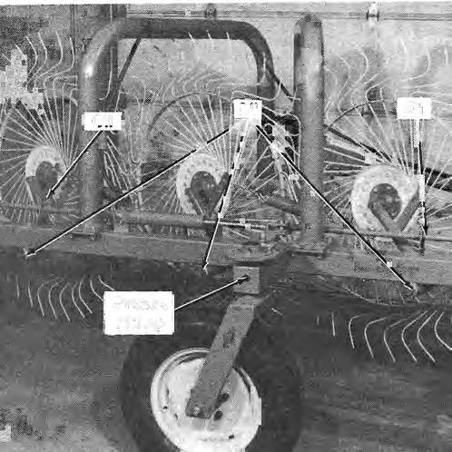
13 When desired or where required, a safety chain should also be obtained and used as a secondary coupling between the tractor and Rake Drawbar. RAKE OPERATION (Figs. 5-6 thru 5-10) Operation for either model Rake is quite similar with the 219 model having two additional Finger Wheels extending from the end ofthe Main Frame to provide a nominal 64" (1625 mm). of additional raking width. The way both model Rakes are setup, the Finger Wheels will rotate to the right (clockwise) and the crop will traverse from right to left. Fig. 5-4: Lift System Locked in "Transport" Position For transporting either model Rake on a public highway, first bring the Finger Wheels to their maximum raised position by fully extending the Hydraulic Lift Cylinder. Then, install the Transport Pin. through the hole in the Lift Tube and secure it with the Lock Pin. Next, move the Adjustable (Steering) Wheel to the Transport position and lock it in this position. Then, move the Drawbar to its narrowest setting. BE SURE the Parking Stand is placed in the storage position BEFORE proceeding to transport the Rake. Fig. 5-6 Finger Wheel pressure on the ground is most important to achieving clean raking. Iftoo much pressure is applied against the ground, unnecessary dirt and trash will be brought into the windrow. Although either model Rake has a considerably large working width, when working in grass or hay, it is recommended that the windrow is made NO larger than the pickup capacity of the baler or harvester. In straw or other light, crops, the maximum width can be utilized. Fig. 5-5: Adjustable (Steering) Wheel Locked in "Transport" Position A CAUTION: Because of the overall length of either model Rake, BE SURE to install and use a Slow-moving Vehicle Emblem (SMV) using the Emblem Mounting Bracket provided. For raking with either model Rake, it is advisable to start in the center of the field and rake in a counterclockwise direction. To make the first windrow, place the Adjustable Wheel in hole position B. After t)ie first pass, use the Hydraulic Lift Cylinder to raise the Finger Wheels. Then, turn around, lower the Finger Wheels and, rake the second and first windrows into one combined windrow. Reposition the Adjustable Wheel to hole position C or D, for a wider raking width and proceed to rake the rest of the field. At the end, rake the headlands. 11


14 Fig. 5-7 : Fig. 5-9 Fig. 5-8 Fig. 5-10: WR219 with Main Frame Extension & Two Additional Finger Wheels 12

 NOTE: Proper Finger Wheel pressure on the ground is an important factor for achieving clean raking.")

 The Rake working width is set with the Adjustable Wheel.")


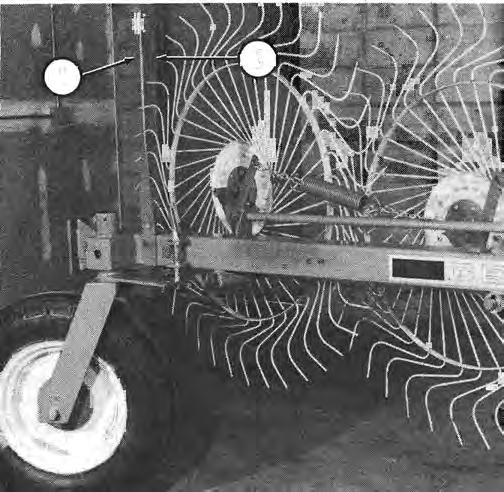
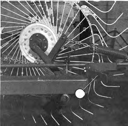
15 TMENTS CAUTION: BEFORE proceeding to make any adjustments on the Finger Wheel Rake, BE SURE to follow the MANDATORY SAFE TY SHUTDOWN PROCEDURE and place the tractor transmission in park and/or lock the brakes, to shut off the engine and, to remove the ignition key and take it with you BEFORE leaving the tractor seat. GROUND PRESSURE (Fig. 6-1) NOTE: Proper Finger Wheel pressure on the ground is an important factor for achieving clean raking. Too much pressure will cause undue stress on the Finger Wheel Tines and cause unnecessary dirt and trash to be brought into the windrow. The Finger Wheels are linked to the Frame by Rake Arms. BE SURE that the Rake Arms are free to pivot and proceed to adjust the ground pressure in the following manner: CHAPTER 6 WORKING WIDTH (Figs. 6-2, 6-3 & 6-4) The Rake working width is set with the Adjustable Wheel. The Rake position, with respect to the tractor, is adjusted with the Drawbar. It is recommended that the Drawbar be attached to the swinging hitch of the tractor. For optional hookup to the 3-point linkage drawbar of the tractor, the Rake can be connected in a hole farther to the right to obtain a better tractor-rake tracking and alignment. 1. Place the tractor and connected Rake on a flat base. 2. Connect the Lift Cylinder Hose to the tractor remote outlet. Fig Lower the Finger Wheels until they just touch the ground. Fig. 5-3: Drawbar Latched in "Transport" Position 4. Check the ground pressure of each Finger Wheel by lifting each Finger Wheel assembly. 5. Adjust the anchor point of the Lift Spring to the appropriate Chain Links position to balance all the Finger Wheels evenly. While raking, the ground pressure is correct if the crop is raked away cleanly. Too great a ground pressure will tend to distort the windrow, cause dirt to get into the crop and cause undue Tooth wear. Fig

 To maintain proper operation, all revolving parts and hinge points MUST move smoothly and be kept well lubricated. Grease the following points at regular 10 hour intervals: 1.")
 A CAUTION: Our Company does NOT sell replacement Tires.")


16 MAINTENANCE & SERVICE HARDWARE (Fig. 7-1) After the first hour of operation, check all attaching hardware, especially in the areas of the Tine anchor bolts and Finger Wheel Hubs. Hardware torques should be checked' on a routine basis after every 10 hours of operation. CHAPTER 7 Check the Rake Tire pressure after every 50 hours of operation. Tires should be inflated to 28 PSIG (196 kpa). Wheel Bolt torques should also be checked after every 50 hours of operation and tightened with 110 ft-ib (150 Nm).torque. Fig. 7-1 LUBRICATION (Figs. 7-1 thru 7-4) To maintain proper operation, all revolving parts and hinge points MUST move smoothly and be kept well lubricated. Grease the following points at regular 10 hour intervals: 1. Adjusting Wheel 2. Pivoting Wheel Oil the following points at regular 10 hour intervals: 3. Parking Stand 4. Pivot points of the Rake Arms (7 or 9 Places) 5. Lift Rod Pivot Points 6. Drawbar Pivot Points 7. Drawbar Pin TIRES & WHEELS (See Figs. 7-2 & 7-3) A CAUTION: Our Company does NOT sell replacement Tires. In addition, Tire mounting, repair and replacement should ONLY be attempted by a qualified tire manufacturer's representative or by properly trained personnel following the tire manufacturer's instruction. If you do NOT have such instructions, contact your tire dealer or the Company. Fig. 7-2: Adjustable Wheel A WARNING: Inflating or servicing tires can be dangerous. Whenever possible, trained personnel should be called to service andl or mount tires. In addition, do NOT place fingers on tire bead during inflation; serious injury or amputation could result! In any event, to avoid possible fatal or serious injury, follow the safety precautions below: BE SURE the Rim is clean and free of rust. Lubricate both the tire beads and rim flanges with a soap solution. Do NOT use oil or grease. Use a clip-on tire chuck with a remote hose and gauge which allows you to stand clear of the tire while inflating it. NEVER inflate beyond 35 PSI (240 kpa) to seat the beads. If beads have NOT seated by the time the pressure reaches 35 PSI, deflate the assembly, reposition the tire on the rim, relubricate both parts and reinflate it. Inflation pressure beyond 35 PSI with unseated beads may break the bead or rim with explosive force sufficient to cause fatal or serious injury. After seating the beads, adjust the inflation pressure to the recommended operating pressure listed. Do NOT weld, braze, or otherwise attempt to repair and use a damaged rim. 14

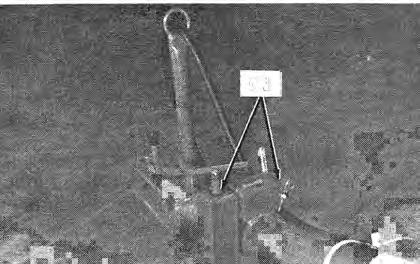

17 Fig. 7-3: Pivoting (Steering) Wheel Fig. 7-4: Parking Stand 15


 be used")

 Wheel assembly with the we,lded-on Frames using (4 each) M16 x 55mm Cap")

18 SET-UP & ASSEMBLY NOTE: These assembly procedures should be performed inside an enclosed workshop equipped with an overhead hoist to facilitate lifting some of the heavier components or otherwise another person should be available to assist in lifting. UNCRATING The model 217 Finger Wheel Rake is shipped from the factory packaged in a plywood crate. To assemble a model 219 Finger Wheel Rake, use the same procedure as for a model 217 and assemble the Main frame Extension, the two additional Finger Wheels, Rake Arms, Supports and Linkages per the details at the end of this chapter. Begin setup by removing all of the components from the crate and laying them out in an orderly fashion. RAKE ASSEMBLY (Figs. 8-1 thru 8-11) After the components have been removed from the shipping crate, refer to the exploded view parts illustrations, parts lists and the photographs provided and proceed as follows: CHAPTER 8 Fig At the Front Main Frame Bearing Pivot, install the Pivoting (Swiveling) Wheel and Brake assembly. Pass the Fork Shaft thru the top and bottom Pivot Bushings and the Brake Disc while maintaining the Disc between A (non-chipable material) be used to cushion the top and bottom halves of the Brake Plates. Then, WARNING: ALWAYS wear Safety Glasses with Side Shields when striking metal. In addition, it is recommended that a softer the blow. Failure to heed could result in secure the Disc to the Shaft with the lox 75m.riJ. Spring serious injury to the eye(s) or other partes) of Pin. the body. 5. At the Rear Main Frame Bearing Pivot, instan the 1. Properly orient and assemble the Front and Rear Main Adjusting (Steering) Wheel assembly with the we,lded-on Frames using (4 each) M16 x 55mm Cap Screws and Plate positioned below the Adjustment Pin Bracket. M16 Lock Nuts. Secure the Wheel Fork Shaft into the Bearing Pivot with the Lock Ring and the lox 75mm Spring Pin. Lock the 2. Properly orient and loosely attach the Right Hand (RH) position of the Adjusting Wheel by installing the Wheel Secondary Frame (assembly with sector) to the Front Main Frame using (4 each) M16 x 55mm Cap Screws and M 16 Lock Nuts. 3. Properly orient and loosely attach the Left Hand (LH) Secondary Frame to the Rear Main Frame using ( 4 each) M16 x 55mm Cap Screws and M16 Lock Nuts. Adjustment Pin and Hairpin Cotter Pin. Fig. 8-1 Fig


.")


19 6. Insert the two sections of the Lift Rod thru the appropriate Brackets on the sides of the Front and Rear Main Frames. Join the Lift Rod sections with the Rod Coupling and (2 each) M8 x 55mm Cap Screws and M8 Lock Nuts. -Fig. 8-6 Fig Properly orient and attach the Drawbar to the Drawbar Pivot Brackets on the Right Hand and Left Hand Secondary Frames and secure it with the large Drawbar Pivot Pin and an 8 x 55mm Spring Pin on the top and bottom. After the Drawbar is pinned to the Frames, tightly secure the hardware left loose in steps 2 & 3. Then, raise the tractor hitch end and install the Jack Stand, securing it with the Jack Stand Pin and Hairpin Cotter Pin, and the Hydraulic Hose Stand, securing it with the large Cotter Pin. 8. Using a wide-headed rubber mallet, install a Pivot Bushing into each side of the welded-on Pivot Tubes, for the Rake Arms, underneath the Main Frames. 9. Generously lubricate the pipe portions of the Rake Arms with grease and properly orient and install the Rake Arms into the Bushings (installed in step 8). Secure each Arm with a large Washer and a 8 x 55mm Spring Pin. 10. Using a Shackle and a Lift Chain Bracket, anchor one end ofa Lifting Chain to a corresponding hole in the Lift Rod. Then, pass the Chain thru a Lift Spring and attach the other end of the Chain to the Bracket on the Rake Arm with another Shackle. (Repeat this process for each ofthe Lift Chains, Springs and Rake Arms.) 11. Properly orient and secure the anchor end of the Lift Cylinder assembly to the Bracket on the Main Frame with the Hydraulic Cylinder Pivot Pin and two 6 x 50mm Cotter Pins. Properly orient and secure the Hydraulic Fig. 8-5 Fig

 and")
 the extra slack and anchor the Hose to the Drawbar using the three Nylon")

, attach the SMV Bracket and")


20 Cylinder Clamp to the Clevis on the end of the Cylinder Rod. Then, with the Cylinder Rod fully retracted, slide the Lift Rod rearward so that the Rod Coupling contacts the adjoining welded-on Lift Rod Support Bracket. Then, secure the Cylinder Clamp around the Lift Rod and anchor the Clamp to the Rod with (2 each) M8 x 55mm Cap Screws and M8 Lock Nuts. 12. Route the Cylinder connection end of the Hydraulic Hose thru the Eyelet in the Hose Stand, along the Drawbar, up, thru (the two welded-on Hose Guide Tubes) and around the Right Hand Secondary Frame and connect it to the port of the Lift Cylinder using pipe sealing compound or teflon tape. After the Hose is connected, drawback (toward the tractor connection end of the Drawbar) the extra slack and anchor the Hose to the Drawbar using the three Nylon Ties provided. Fig. 8-9 REFLECTOR & SMV EMBLEM BRACKETS (Fig & see Fig. 8-3) 16. Referring to the appropriate photograph provided and on the end of the Front Frame, attach the Mounting Reflector Bracket,in the position and direction shown, using the same two MI0 x 35mm Bolts and Nuts used to secure the Rod Support Bracket. Fig Likewise, referring to the appropriate photograph provided and on the end of the Rear Frame (or Frame Extension, for the 219 model), attach the SMV Bracket and Mounting Bracket around the Frame with (2 each) 5/16 x 3/4 Carriage Bolts and 5/16 Lock Nuts, in the manner illustrated. 13. Connect the Rake to the tractor drawbar and plug the Lift Cylinder Hose into a remote outlet on the tractor. NOTE: A standard ISO Male Quick Disconnect Coupler is furnished with either model Rake. As, required and to match the Female Disconnect port on your particular model tractor, the appropriate Quick Disconnect coupler may have to be purchased locally. 14. Start the tractor engine and operate the remote outlet control to fully extend the Lift Cylinder. Then, shut the tractor off and install the Transport Pin, thru the hole in the Lift Rod and install the Hairpin Cotter Pin to lock the Lift Cylinder in the fully extended position. 15. Install the Hubs and Finger Wheels onto the Spindles of the Rake Arms as illustrated. Readjust the Lift Chains per details in the Adjustment chapter of this manual. Fig
 M8 x 55mm Cap")
 Rake Arms, Lift Chains, Lift Springs and")


21 19. Insert the Extension Rod Tube thru the holes in the Rod Supports of the Main Frame Extension. Then, in a similar manner as step 6, join the Lift Rod sections with another Rod Coupling and (2 each) M8 x 55mm Cap Screws and M8 Lock Nuts. 20. In a similar manner as steps 8 thru 11, 14 and 15, install the (2 each) Rake Arms, Lift Chains, Lift Springs and Finger Wheels to the Frame Extension and Extension Lift Rod. Then, make similar Lift system adjustments as per details in the Adjustments chapter of this manual. 21. In a similar manner as step 9, properly orient and install the two Rake Arms into the Bushings (installed in step 18). Secure each Arm with a large Washer and a 8 x 55mm Spring Pin. Fig WHEEL RAKE ASSEMBLY (Fig & see Figs. 8-1 thru 8-11) NOTE: All of the components, installed in steps 1 thru 15, MUST be installed BEFORE proceeding to install the 9-Wheel Main Frame Extension, Rake Arms, Finger Wheels and related assemblies. Proceed as follows: 18. In the same manner as step 1, properly orient and attach the Main Frame Extension to the end of the Rear Main Frame using (4 each) M16 x 55mm Cap Screws and M16 Lock Nuts. Fig

, compare all of the various closeup location photographs to your machine, before starting to refinish the unit.")


 become(s) damaged, or if the unit is repainted,replace the Decal(s).")
22 DECAL LOCATIONS GENERAL INFORMATION Decal Locations information is provided to assist in the proper selection and application of new decals, in the event the original decal ( s) become( s) damaged or the machine is repainted. Refer to the listing for the illustration refererice number, part number, description and quantity of each decal provided in the Kit. Refer to the appropriate illustration(s) for replacement loeation(s). To insure proper selection of the correct replacement decal(s), compare all of the various closeup location photographs to your machine, before starting to refinish the unit. Then, circle each pictured decal (on or otherwise applicable to your machine) while checking-off its part number in the listing. After you have verified all the decals needed for replacement, place any unnecessary decals aside for disposal. NEW DECAL APPLICATION Surfaces MUST be free from dirt, dust, grease and other foreign material before applying the new decal. To apply a solid-formed decal, remove the smaller portion of the decal backing paper and apply this part of the exposed adhesive backing to the clean surface while maintaining proper position and alignment. Peel the other portion of the backing paper off slowly while applying hand pressure to smooth-out decal surface. f'lladtcd Q " ".... 'fij A CAUTION: ALWAYS observe Safety Rules shown on Decals. If Decal(s) become(s) damaged, or if the unit is repainted,replace the Decal(s). If repainting, BE SURE that ALL Decals from the Kit(s), which apply to your machine, are affixed to your unit. The Decal Kit for the WR217 & WR219 Finger Wheel Rakes is The Kit includes the following: Ref. Part No. No. Description & Quantity Red Reflector (2 Places) Amber Reflector WARNING - Install Transport Latch CAUTION - Operator's Responsiblility & Read Manual CAUTION -General Safety G E H l..; with Stripe G E H l..; with Stripe (2 Places) Model Only Model Only NOTICE Order paint for refinishing machines from this list: One Gallon Blaze Paint One Gallon Maize Paint (120z) Cans Blaze Spray Paint (12oz) Cans Maize Spray Paint 20

23 21
24 "uap... ~n.. o \,n I E:n I SERVICE PARTS & NUMERICAL INDEX When ordering service parts, specify the correct part number, full description, quantity required, the unit model number and serial number. The Rake Model and Serial Number is stamped on a plate located on the back side of the Moveable Head. HRight H and HLeftH are determined from a position standing behind the Rake and facing the direction of travel. G E H L Company reserves the right to make changes or improvements in the design or construction of any part of the unit without incurring the obligation to install such changes on any unit previously delivered. Common attaching hardware, such as Cotter Pins, Set Screws, Woodruff Keys, Screws, Nuts, etc., are included in the parts lists, indented below the part it is (they are) associated with. 22
25 217 MAIN FRAME 26~ ~\ i~ -~..27 ~ 24 ~& l ' I. -~ - \ 23 ~ I I ~ - ~ 22 /~1 29 r. 21 I -- ~ l ~ 2~ 20' 13~ 2-""<I!)Q'';/ REF PART QTY NO NUMBER PART DESCRIPTION...ETC. REQ SOCKET, SMV EMBLEM CS 5/16X3/ SMV BRACKET CS 5/16X3/ ~ BRACKET, MOUNTING ROD, LIFT ARM, RAKE REF PART QTY SHIELD, BEARING NO NUMBER PART DESCRIPTION...ETC.. REQ BEARING, BALL HUB BRACKET, LIFT ROD SUPPORT CS 8.8/M10X CS 8.8/M10X NUT, HEX M M10 LN WASHER M BRACKET, LIFT CHAIN BEARING, BALL CS 8. 8/M8X NUT, LOCK M18-1, M8 LN CAP, HUB PIN, TRANSPORT 10MM DIA SHACKLE PIN, HAIRPIN COTTER 2.5MM CHAIN, 65CM. LIFT BRACKET, MTG. REFLECTOR SPRING, LIFT PIN, HYD. CYLINDER ANCHOR COUPLING, ROD PIN, COTTER 6 X CS 8. 8/M8X a CYLINDER, HYDRAULIC M8 LN CLAMP, HYDRAULIC CYLINDER FRAME, SECONDARY LH CS 8. 8/M8X CS 8.8/M14X M8 LN M14 LN CONNECTOR, HyDRAULIC CS 8.8/M16X HOSE, HYDRAULIC M16 LN FRAME, FRONT MAIN FRAME, SECONDARY RH FRAME, REAR MAIN CS 8.8M16X CS 8. 8/M16X M16 LN M16 LN TIE, NYLON BUSHING, PIVOT COUPLER, HYD. DISCONNECT /4 PLAIN WASHER PIN, SPRING (8 X 55)... 7 a) FOR SEAL KIT, ORDER
26 219 MAIN FRAME EXTENSION REF NO PART NUMBER QTY PART DESCRIPTION...ETC.. REQ ~ 3 6~ ~ e>\ 8g.-@e I 7 ~@ r~ ~ l ! _~ 1 10 ~ I e ') ') ~,,/ /".,/ Y1i--~ COUPLING, ROD... 1 CS 8. 8/M8X M8 LN... 2 BRACKET, LIFT CHAIN... 2 CS 8. 8/M8X M8 LN... 2 SHACKLE... 4 CHAIN, 65CM. LIFT... 2 SPRING, LIFT... 2 CAP, HUB... 2 NUT,LOCK M BEARING, BALL... 2 HUB... 2 CS 8.8/M10X NUT, HEX M WASHER M BEARING, BALL... 2 SHIELD, BEARING... 2 ARM, RAKE... 2 BUSHING, PIVOT... 4 ROD, EXTENSION LIFT... 1 FRAME, EXTENSION... 1 CS 8. 8/M16X M16 LN /4 PLAIN WASHER... 2 PIN, SPRING (8 X 55)... 2 FINGER WHEEL ASSEMBLY REF NO PART NUMBER PART DESCRIPTION... ETC.. QTY REQ FINGER WHEEL ASSM. (RH).. CONSISTS OF: TINE... RIM... BOLT, TOOTH... NUT, M10/ CLIP... PLATE, TINE... AR
27 REF PART NO NUMBER PART DESCRIPTION...ETC.. QTY REQ REF NO PART NUMBER QTY PART DESCRIPTION...ETC.. REQ STAND, HYDRAULIC HOSE PIN, COTTER 5/16X3-1/ STAND PIN, STAND PIN, HAIRPIN COTTER 2.5MM PIN, DRAWBAR... 1 PIN, SPRING (8 X 55)... 3 PIN, DRAW BAR PIVOT... 1 SPRING, COMPRESSION... 1 DRAWBAR
28 PIVOTING (STEERING) WHEEL ASSEMBLY REF NO PART NUMBER PART DESCRIPTION... ETC.. QTY REQ REF NO PART NUMBER QTY PART DESCRIPTION...ETC.. REQ SPRING, BRAKE... PLATE, BRAKE (2 PIECE)... CS 8. 8M12X90... M12 LN... 1/4 PLAIN WASHER... DISC... PIN, SPRING 10 X BUSHING, WHEEL FORK PIVOT FITTING, GREASE M10X1... WHEEL FORK, PIVOTING BOLT, WHEEL FORK M M20-1, 5 HEX LOCK NUT... 1 RIM... 1 SPACER, WHEEL FORK... 2 COVER, DUST (WASHER)... 2 BEARING, BALL (6207-2RS). 2 HUB... 1 BOLT, HUB 16X NUT, CONICAL LUG 16MM... 5 SPINDLE
29 ADJUSTING WHEEL ASSEMBLY 8~... ~. 9 REF PART OTY REF PART OTY NO NUMBER PART DESCRIPTION... ETC.. REO NO NUMBER PART DESCRIPTION... ETC.. REO RING, LOCK RIM PIN, SPRING 10X SPACER, WHEEL FORK USHING, WHEEL FORK PIVOT COVER, DUST (WASHER) PIN, WHEEL ADJUSTMENT BEARING, BALL (6207-2RS) PIN, HAIRPIN COTTER 4MM HUB FITTING, GREASE M10X BOLT, HUB 16X WHEEL FORK, ADJUSTING NUT, CONICAL LUG 16MM BOLT, WHEEL FORK M SPINDLE M20~1.5 HEX LOCK NUT
30 ~ PART PAGE REF. PART PAGE REF. PART PAGE REF. NO. NO. NO. NO. NO. NO. NO. NO. NO PART PAGE REF. NO. NO. NO
31 INDEX Page A Adjustments Ground Pressure Working Width C Checklists Pre-delivery Delivery D Decal Locations General Information New Decal Application I Introduction... 2 M Maintenance & Service Hardware Lubrication Tires & Wheels MANDATORY SAFETY SHUTDOWN PRO CEDURE... 8 o Operation Emergency Shutdown General Information Page Mounting to Tractor Transporting Rake Operation S Safety Service Parts & Numerical Index Main Frame Main Frame Finger Wheel Assembly Drawbar & Stands Pivoting (Steering) Wheel Assembly Adjusting Wheels Assembly: Set-up & Assembly Uncrating Rake Assembly Reflector & SMV Emblem Brackets Wheel Rake Assembly Standard Hardware Torque Inside Back Cover T Table of Contents W Warranty Inside Front Cover General Bolt Torque Data in Ft-Lb* BOLT SIZE GRADE Metric M6 M8 MIO MI2 MI4 MI6 DRY LUB. DRY LUB. DRY LUB II " *Multiply by (1.355) for metric Nm to


32 FARM EQUIPMENT GEHL COMPANY WEST BEND. WISCONSIN U.S.A /1P388 (68) Gehl Company 1988 Printed in U.S.A.
Form No Replaces. Finger Wheel Rake OPERATOR'S AND SERVICE PARTS MANUAL
 Form No. 903031 Replaces 902521 Finger Wheel Rake OPERATOR'S AND SERVICE PARTS MANUAL GEHL COMPANY New Agricultural Equipment Gehl Company (Incorporated), hereinafter referred to as GEHL, as manufacturer
R T SERIES ROTARY TILLER
 R T SERIES ROTARY TILLER Operating and Maintenance Manual TABLE OF CONTENTS 1. PRODUCT WARRANTY. 3 2. CHECKLIST Dealer s File Copy. 4 Customer s File Copy.. 5 3. INTRODUCTION 6 4. SPECIFICATIONS.. 7 5.
Extreme Duty Grapple (Rock, Skeleton, Scrap & Tine) Operation and Maintenance Manual
 Operation and Maintenance Manual") Extreme Duty Grapple (Rock, Skeleton, Scrap & Tine) Operation and Maintenance Manual Revision Date: May 12, 2017 Skid Pro PO Box 982 Alexandria, MN 56308 Toll Free: 877-378-4642 www.skidpro.com TABLE OF
Extreme Duty Grapple (Rock, Skeleton, Scrap & Tine) Operation and Maintenance Manual Revision Date: May 12, 2017 Skid Pro PO Box 982 Alexandria, MN 56308 Toll Free: 877-378-4642 www.skidpro.com TABLE OF
OWNER S, INSTALLATION AND PARTS MANUAL
 OWNER S, INSTALLATION AND PARTS MANUAL QUICK HITCH CONVERSION KIT CONVERTS 24/MT TO 26 SERIES HITCH FOR PLOW SERIAL NUMBERS AFTER 24G100000 24D100000 MTD200000 MTG200000 2005 Sno-Way International 97101198A
Operator s/parts Manual
 Operator s/parts Manual 3-Point Solid Stand Drills Pull Hitch Package Manufacturing, Inc. P.O. Box 5060 Salina, Kansas 67402-5060! Read the operator s manual entirely. When you see this symbol, the subsequent
ROTARY RAKE OPERATOR'S MANUAL
 MODEL 1150 ROTARY RAKE OPERATOR'S MANUAL DO NOT OPERATE THIS EQUIPMENT UNTIL THIS MANUAL HAS BEEN READ AND UNDERSTOOD. Part Number: 17.00801C May 2005 Miller-St. Nazianz, Inc. P.O. Box 127 St. Nazianz,
OPERATO 'S AND SERVICE PARTS MANUAL
 Form No. 903468 Replaces 903033 V-Rakes ~ ~ [Q1 ~,~~,t~1"'\w\~ lil.i~ @. I ~ WR308 ((. OPERATO 'S AND SERVICE PARTS MANUAL GEHL COMPANY New Agricultural Equipment Gehl Company (incorporated), hereinafter
Planting Components. Operator s/parts Manual. Row Cleaner VIII. Terra-Tine
 Operator s/parts Manual Terra-Tine Row Cleaner VIII Planting Components! Read the operator s manual entirely. When you see this symbol, the subsequent instructions and warnings are serious - follow without
MODELS EWR820, EWR1023, EWR1227 PULL TYPE HAY RAKES PARTS MANUAL SECTION 19
 EWR MODELS EWR820, EWR1023, EWR1227 PULL TYPE HAY RAKES Published 04/11 PARTS MANUAL SECTION 19 MATERIAL HANDLING PARTS MANUAL PARTS ORDERING GUIDE The following instructions are offered to help eliminate
HT /243 REPLACES. Tedder. OPERATOR'S AND SERVICE PARTS MANUAL l!i
 HT 24 242/243 904328 REPLACES 90434 Tedder OPERATOR'S AND SERVICE PARTS MANUAL l!i G E H I...: COMPANY New Agricultural Equipment G E H I...: Company (Inc.), hereinafter referred to as G E H...:, warrants
FORAGE BOX MODEL 5300 REAR UNLOAD OPERATOR'S MANUAL DO NOT OPERATE THIS EQUIPMENT UNTIL THIS MANUAL HAS BEEN READ AND UNDERSTOOD.
 FORAGE BOX MODEL 5300 REAR UNLOAD OPERATOR'S MANUAL DO NOT OPERATE THIS EQUIPMENT UNTIL THIS MANUAL HAS BEEN READ AND UNDERSTOOD. Miller-St. Nazianz, Inc. Art s-way Manufacturing Co., Inc. P.O. Box 127
Update Manual. Manufacturing, Inc. 7 & 10 End Wheel No-Till Clutch Linkage. P.O. Box 218 Assaria, Kansas Effective 5/3/ M
 Update Manual 7 & 10 End Wheel No-Till Clutch Linkage Manufacturing, Inc. P.O. Box 218 Assaria, Kansas 67416 Effective 5/3/96 152-156M General Information General Information Important Notice Great Plains
OWNER S, INSTALLATION AND PARTS MANUAL
 OWNER S, INSTALLATION AND PARTS MANUAL QUICK HITCH CONVERSION KIT CONVERTS ST TO 22 SERIES HITCH FOR PLOW SERIAL NUMBERS AFTER STD100000 STG100000 2006 Sno-Way International 97101306A TABLE OF CONTENTS
TABLE OF CONTENTS. Warranty Disclaimers Delivery Checklist After Sale Checklist Safety Set Up... 8
 TABLE OF CONTENTS Pickett Equipment Warranty... 2 Warranty Disclaimers... 3 Delivery Checklist... 4 After Sale Checklist... 4 Safety... 5-7 Set Up... 8 Machine Adjustments and Operation... 9 Maintenance
TABLE OF CONTENTS. 2. CHECKLIST Dealer s File Copy. 4 Customer s File Copy INTRODUCTION SPECIFICATIONS... 7
 TABLE OF CONTENTS 1. PRODUCT WARRANTY. 3 2. CHECKLIST Dealer s File Copy. 4 Customer s File Copy... 5 3. INTRODUCTION. 6 4. SPECIFICATIONS... 7 5. SAFETY. 8-9 5.1 Mandatory Safety Shutdown Procedure. 9-11
INSTALLATION AND PARTS MANUAL
 INSTALLATION AND PARTS MANUAL AUXILIARY LIGHT AND MOUNTING PACKAGE 99100195 AFTER S/N ALP100085 FOR PLOW SERIAL NUMBERS AFTER 18M100000 18DX100000 97100338A TABLE OF CONTENTS INTRODUCTION... 2 WARNINGS...
Planting Components. Operator s/parts Manual Terra-Tine. Row Cleaner
 Operator s/parts Manual Terra-Tine Row Cleaner Planting Components! Read the operator s manual entirely. When you see this symbol, the subsequent instructions and warnings are serious - follow without
MidCap Rake MCR8 MCR10 MCR12
 MidCap Rake MCR8 MCR10 MCR12 Operator s Manual Counter Balance Valves for Steady Single Side Raking Model MCR8 3 Collection width Settings Individual Spring Adjustment THIS MANUAL MUST BE READ AND UNDERSTOOD
610 BUSHEL MANURE SPREADER
 610 BUSHEL MANURE SPREADER RODA MANUFACTURING 1008 LOCUST ST. HULL, IA. 51239 Art s-way Manufacturing 712-439-2366 Co., Inc. Hwy 9 West - PO Box 288 WWW.RODAMFG.COM Armstrong, IA. 50514 U.S.A 2 INTRODUCTION
SHEYENNE TELE-BOOM OWNERS MANUAL OPERATOR INSTRUCTIONS PARTS BOOK
 SHEYENNE TELE-BOOM OWNERS MANUAL OPERATOR INSTRUCTIONS PARTS BOOK 701 Lenham Ave. SW PO Box 647 Cooperstown ND 58425 1-800-797-1883 701-797-2700 * 701-797-2584 Fax www.sheyennemfg.com TABLE OF CONTENTS
VR482 Hay Rake OPERATOR & PARTS MANUAL. Last Updated: May 12, 2014
 VR482 Hay Rake OPERATOR & PARTS MANUAL Last Updated: May 12, 2014 Bridgeview Manufacturing Inc. P.O. Box 4 Gerald, SK S0A 1B0 (306) 745-2711 www.bridgeviewmanufacturing.com bmi@sasktel.net Your Authorized
MK AUGERS POWER SWING KIT ASSEMBLY & OPERATION MANUAL
 MK AUGERS POWER SWING KIT ASSEMBLY & OPERATION MANUAL Read this manual before using product. Failure to follow instructions and safety precautions can result in serious injury, death, or property damage.
Model 35 PARTS MANUAL
 Model 35 PARTS MANUAL Version 3-2007 Ashland Industries Inc. 1115 Rail Drive P.O. Box 717 Ashland, WI. 54806 Ph: 877-634-4622 Toll Free Ph: 715-682-4622 Fx: 715-682-9717 www.ashlandind.com Model 35 Scraper
Planting Components. Operator s/parts Manual
 Operator s/parts Manual Unit Mount Conservation Coulter and Spring Package Attachment for JD 7000, JD 7200, White 6100, Kinze Planters and Great Plains Row Units Planting Components! Read the operator
INSTALLATION & PART S MANUAL
 INSTALLATION & PART S MANUAL CONVERSION KIT 96110119 FOR CONVERTING SNO-WAY S STANDARD LIGHTING KITS (96102357 and 96106606) TO THE EIS KIT Sno-Way, Down Pressure and EIS are registered trademarks of Sno-Way
Operator s Manual. Go Galvanized! YOU'RE ALWAYS AHEAD...WITH A MODERN BEHIND.
 SUMMER 2008 rock & landscape rake Operator s Manual 003-7445 003-7450 003-7460 003-7440 003-7445 003-7450 YOU'RE ALWAYS AHEAD...WITH A MODERN BEHIND. P.O. Box 790 Beaumont, Tx 77704 409.833.2665 1.800.231.8198
3800 SERIES SINGLE HYDRAULIC LOCKING TOOLBAR
 3800 SERIES SINGLE HYDRAULIC LOCKING TOOLBAR 2565-774_REV_D 02/2018 OPERATOR S MANUAL PART IDENTIFICATION YETTER MANUFACTURING CO. FOUNDED 1930 Colchester, IL 62326-0358 Toll free: 800/447-5777 309/776-3222
480T All-Wheel-Steer. Loader
 480T All-Wheel-Steer Form No. 918119 Revision C Loader Beginning Serial Number: 342100107 PARTS MANUAL Introduction When ordering service parts, specify the correct part number, full description, quantity
Impeller Disc Mower Conditioner
 252 Form No. 90987 Revision B Impeller Disc Mower Conditioner OPERATOR S MANUAL GEHL NEW AGRICULTURAL EQUIPMENT IMPELLER DISC MOWER CONDITIONER WARRANTY GEHL AGRICULTURE DIVISION of the GEHL COMPANY, hereinafter
LUBRICATOR GUN INSTRUCTIONS-PARTS LIST. 10,000 psi (700 bar) Maximum Delivery Pressure. Detachable-type
 Maximum Delivery Pressure. Detachable-type") INSTRUCTIONS-PARTS LIST 306 460 INSTRUCTIONS This manual contains important warnings and information. READ AND KEEP FOR REFERENCE. Rev. E Supercedes D Detachable-type LUBRICATOR GUN 10,000 psi (700 bar)
INSTRUCTIONS-PARTS LIST 306 460 INSTRUCTIONS This manual contains important warnings and information. READ AND KEEP FOR REFERENCE. Rev. E Supercedes D Detachable-type LUBRICATOR GUN 10,000 psi (700 bar)
ATV TRACK KIT. Operator s Manual Installation Instructions Service Instructions Replacement Parts List. Effective Date: October, 2012
 p/n 2258-642 ATV TRACK KIT Operator s Manual Installation Instructions Service Instructions Replacement Parts List Track Assembly Kits (p/n 1436-204) Mounting Assembly Kits (p/n 1436-205) 1436-815) Effective
Lubricator Gun: 10,000 psi (700 bar) Maximum Delivery Pressure when disconnected from Dispenser
 Maximum Delivery Pressure when disconnected from Dispenser") INSTRUCTIONS-PARTS LIST 30 455 INSTRUCTIONS This manual contains important warnings and information. READ AND KEEP FOR REFERENCE. Rev. C Supercedes B Hand-Operated Portable Grease Dispenser Buckshot Luber
INSTRUCTIONS-PARTS LIST 30 455 INSTRUCTIONS This manual contains important warnings and information. READ AND KEEP FOR REFERENCE. Rev. C Supercedes B Hand-Operated Portable Grease Dispenser Buckshot Luber
LEWIS WINDROWER OWNER / OPERATOR MANUAL
 LEWIS WINDROWER OWNER / OPERATOR MANUAL MODEL # WR-1 WINDROWER Manufactured by: LEWIS BROTHERS MANUFACTURING, INC. Post Office Box 146 Baxley, GA 31513 Tel: (912) 367-4651 Fax: (912) 367-3958 2-21-14 1
25 BUSHEL MANURE SPREADER
 25 BUSHEL MANURE SPREADER RODA MANUFACTURING 338 MAIN ST. HULL, IA. 51239 Art s-way Manufacturing 712-439-2366 Co., Inc. Hwy 9 West - PO Box 288 WWW.RODAMFG.COM Armstrong, IA. 50514 U.S.A 2 INTRODUCTION
TABLE OF CONTENTS DESCRIPTION. Safety Instructions & Safety Sign Locations Operating Instructions Assembly Instructions...
 TABLE OF CONTENTS DESCRIPTION PAGE Warranty... 1 Safety Instructions & Safety Sign Locations... 2 Operating Instructions... 3 Assembly Instructions... 5 500 & 600 Snowblower Drawings... 8 500 & 600 Snowblower
Operator s Manual. Go Galvanized! YOU'RE ALWAYS AHEAD...WITH A MODERN BEHIND.
 SUMMER 2008 C2 tilting grader blade Operator s Manual YOU'RE ALWAYS AHEAD...WITH A MODERN BEHIND. 003-5336 003-5342 003-5531 003-5544 P.O. Box 790 Beaumont, Tx 77704 409.833.2665 1.800.231.8198 Fax: 409.726.8333
OPERATOR'S MANUAL & PARTS CATALOG 12 TON RUNNING GEAR
 Unverferth Grain Handling Systems OPERATOR'S MANUAL & PARTS CATALOG 1 TON RUNNING GEAR Model RGE- Unverferth Manufacturing Co., Inc. Box 7 Kalida, OH 8 Part No. 00 PH: 1-- FAX: 1--8 www.unverferth.com
CAM-LIFT WHEEL MOVE KIT 1500-SERIES S-DRIVE STANDARD CONVEYORS ASSEMBLY MANUAL
 CAM-LIFT WHEEL MOVE KIT ASSEMBLY MANUAL This manual applies to the following models: 1565, 1575, 1585, 1590, 15100 ORIGINAL INSTRUCTIONS Read this manual before using product. Failure to follow instructions
INSTALLATION MANUAL SWS
 INSTALLATION MANUAL SWS 30-30 Gallon Auxiliary Tank FOR RVB1500, 2000, 2500 SPREADERS Sno-Way, Down Pressure and EIS are registered trademarks of Sno-Way International, Inc. ProControl, MegaBlade, V-Wing,
Richmond Conveyor. Hydraulic Ultimate Manual. January 2013
 Richmond Conveyor Hydraulic Ultimate Manual January 2013 Table of Contents Operators Manual Removing conveyor from truck Maintenance checklist Maintenance kit material list Safety information Index Installation
Operating Instructions and Parts Manual 3-1/2 ton Farm Jack Model FJ-3-1/2A
 Operating Instructions and Parts Manual 3-1/2 ton Farm Jack Model FJ-3-1/2A JET 427 New Sanford Road LaVergne, Tennessee 37086 Part No. M-440436 Ph.: 800-274-6848 Revision A1 06/2014 www.jettools.com Copyright
GERINGHOFF. Corn Header Manual f HEADSIGHT.COM
 GERINGHOFF Corn Header Manual 09020701f HEADSIGHT.COM 574.546.5022 About Headsight Headsight Contact Info Headsight, Inc. 4845 3B Road Bremen, IN 46506 Phone: 574-546-5022 Fax: 574-546-5760 Email: info@headsight.com
OWNER S MANUAL 40 LAWN AERATOR SAT-40 BH. Assembly Installation Operation Repair Parts. Visit us on the web! MODEL:
 OWNER S MANUAL 40 LAWN AERATOR MODEL: SAT-40 BH Assembly Installation Operation Repair Parts For the latest product updates & setup tips: Visit us on the web! www.brinly.com Important: This manual contains
Operator s Manual. Go Galvanized! YOU'RE ALWAYS AHEAD...WITH A MODERN BEHIND.
 fall 2010 3pt & quick attach Bale spears & 3pt bale carrier Operator s Manual YOU'RE ALWAYS AHEAD...WITH A MODERN BEHIND. 318-1006-i 318-1005-i 020-1500 020-1502 P.O. Box 790 Beaumont, Tx 77704 409.833.2665
Operator s Manual. Sabre Crop Divider
 Operator s Manual Sabre Crop Divider Canadian Agri Technologies Inc. 47 Halparin Drive Winnipeg, MB. R3X 1Z9 ph. 204 992.2484 fax. 204 237.0552 www.sabredivider.com TOLL FREE PARTS LINE 1 866 792-8437
Predelivery Instructions
 PINK Predelivery Instructions SR5030 Split-Row Planter Manufacturing, Inc. P.O. Box 5060 Salina, Kansas 67402-5060! Read this manual entirely. When you see this symbol, the subsequent instructions and
RED23305 Owner s Manual
 RED23305 Owner s Manual 5 foot, 3-Point Mounted Snow Blower 270 West Park Avenue Huron, SD 57350 866-526-5682 Serial Number: Date of Purchase: Red Devil Snow Blower See Figure 1. 1. The Red Devil Snow
OPERATOR S MANUAL REPAIR PARTS CATALOG. Models: SCP-51 & SCP-71 SCP-52 & SCP-72 SCP-91 & SCP-111 SCP-92 & SCP-112 BRILLION FARM EQUIPMENT
 OPERATOR S MANUAL REPAIR PARTS CATALOG Subsoil Chisel Plow Models: SCP-51 & SCP-71 SCP-52 & SCP-72 SCP-91 & SCP-111 SCP-92 & SCP-112 IMPORTANT! Repairs cannot be purchased retail direct from factory. Order
16K Revolution Service Kit Instructions 86016
 86016 Equipment Required: Wrenches: 15/16, 1 1/8, Torque Wrench, Rubber Mallet Included Service Kit Items: 1 Qty. (1) Wear Plate 2 Qty. (1) Pivot Bushing 3 Qty. (1) Bearing Cup 4 Qty. (1) Bearing 1 5 Qty.
W & A 12 ROW TOP LEVELING STACKER LEVEL BANDER
 W & A 12 ROW TOP LEVELING STACKER LEVEL BANDER NO. 3640 OPERATOR S MANUAL TO THE OWNER: Congratulations on your purchase of a new W & A Top Leveling Stacker Level Bander. Your selection is an indication
BALE KING GT40 Grain Feeder Operator's & Parts Manual Last Update: November 20, 2014 Bridgeview Manufacturing Inc - 1 -
 BALE KING GT40 Grain Feeder Operator's & Parts Manual Last Update: November 20, 2014 Bridgeview Manufacturing Inc - 1 - Your Authorized Dealer: Your Serial Number: The Serial Number is located on the tank.
J. & M. Mfg. Co., Inc. 284 Railroad Street - P.O. Box 547 Fort Recovery, OH Ph: (419) Fax: (419)
 Fax: (419)") OPERATORS MANUAL Rev.8.14.17 Talc Applicator (Hydraulic) J. & M. Mfg. Co., Inc. 284 Railroad Street - P.O. Box 547 Fort Recovery, OH 45846 Ph: (419) 375-2376 Fax: (419) 375-2708 www.jm-inc.com 2 Table
OPERATORS MANUAL Rev.8.14.17 Talc Applicator (Hydraulic) J. & M. Mfg. Co., Inc. 284 Railroad Street - P.O. Box 547 Fort Recovery, OH 45846 Ph: (419) 375-2376 Fax: (419) 375-2708 www.jm-inc.com 2 Table
Two-Stage Snow Blower For 4WD Pick Up Trucks. Operator s Manual
 Two-Stage Snow Blower For 4WD Pick Up Trucks Operator s Manual Distrubuted by: Metal Fabricating LLC P.O. Box 831 Brodheadsville, PA 18322 Phone: 570-992-9989 SnowVac.com WARRANTY POLICY Metal Fabricating
KONGSKILDE Vertical Tillage - Assembly Guide ASSEMBLY INSTRUCTIONS Revision 18 Serial No current Series.
 KONGSKILDE 9100 Vertical Tillage - Assembly Guide Kongskilde 9100 Series *Model may not be exactly as shown. Kongskilde reserves the right to make changes to product designs and specifications without
WARRANTY REGISTRATION AND POLICY
 WARRANTY REGISTRATION AND POLICY Buhler Manufacturing products are warranted for a period of twelve (12) months from original date of purchase, by original purchaser, to be free from defects in material
Tube-Line Techno-Bale 960. Operator's Manual
 Tube-Line Techno-Bale 960 Operator's Manual One- Year Manufacturer's Warranty For Normal Use With The Exception Of Tires If the Equipment does not function properly, or if a piece is defective due to a
OPERATOR S MANUAL. 20-bu 3-Point Hitch Material Collection System. LP65048 Supplier ST /07/2017 English. North American Edition Printed in USA
 OPERATOR S MANUAL 20-bu 3-Point Hitch Material Collection System LP65048 Supplier ST48289 11/07/2017 English North American Edition Printed in USA Introduction Using Your Operator s Manual Read this entire
Walker Loader Bucket OPERATOR S AND PARTS MANUAL
 Walker Loader Bucket OPERATOR S AND PARTS MANUAL Please Read and Save These Instructions For Safety, Read all Safety and Operation Instructions Prior To Operating Machine P/N 6690 TABLE OF CONTENTS Introduction
Talet Equipment International Ltd. Sand Kicker
 Talet Equipment International Ltd. Sand Kicker Parts & Operators Manual P.O. Box 35 Strathmore AB Canada TP K3 www.taletattachments.com sales@taletattachments.com Toll Free -888-37-5878 Fax -403-934-304
Wheel Horse. 36 Tiller. Model No & Up. Operator s Manual
 FORM NO. 8 9 Rev. A Wheel Horse 6 Tiller for Classic Garden Tractors Model No. 7970 690000 & Up Operator s Manual IMPORTANT: Read this manual carefully. It contains information about your safety and the
Owner's Manual LAWN AERATOR MODELS: PA-40 BH PA-48 BH. Assembly Installation Operation Repair Parts
 Owner's Manual LAWN AERATOR MODELS: PA-40 BH PA-48 BH Assembly Installation Operation Repair Parts For use with Riders and Lawn/Garden Tractors IMPORTANT This manual contains information for the safety
Operator and Parts Manual
 Operator and Parts Manual Landscape Rake 60", 72", 84" & 90" Model 092010 FK349 Table of Contents - 60", 72", 84" & 90" Land Rake Table of Contents Introduction...4 Safety...5 Safety...6 General Safety...6
80 Series. Variable Chamber. Round Balers
 80 Series Variable Chamber Form No. 909804 Revision B Round Balers 480 - Before SN800 580 - Before SN400 680 - Before SN7800 780 - Before SN7800 880 - Before SN500 OPERATOR S MANUAL GEHL NEW AGRICULTURAL
General Information. Assembly Instructions. Dual Marker Option
 Installation Instructions 12 Center Pivot Hitch Used with: 12 Center Pivot Hitch General Information! When you see this symbol, the subsequent instructions and warnings are serious - follow without exception.
Tube-Line Techno-Bale 980
 Tube-Line Techno-Bale 980 Operator's Manual 28287 (05/05/11) 2 One- Year Manufacturer's Warranty For Normal Use With The Exception Of Tires If the equipment does not function properly, or if a manufacturing
1000-LB. ENGINE STAND
 1000-LB. ENGINE STAND WARNING: Read carefully and understand all ASSEMBLY AND OPERATION INSTRUCTIONS before operating. Failure to follow the safety rules and other basic safety precautions may result in
Operator and Parts Manual
 Operator and Parts Manual Utility Auger 6" Model 092010 FK339 Table of Contents - 6" Utility Auger Table of Contents Introduction...4 Safety...5 Safety...5 General Safety...6 Start-up Safety...6 Operation
INTAKE HOPPER STX/TF/TFX/WR AUGERS OPERATOR AND ASSEMBLY MANUAL
 INTAKE HOPPER STX/TF/TFX/WR AUGERS OPERATOR AND ASSEMBLY MANUAL Read this manual before using product. Failure to follow instructions and safety precautions can result in serious injury, death, or property
DURABILT INDUSTRIES, LLC
 DURABILT INDUSTRIES, LLC Pocahontas, AR 72455 Phone: 870-892-4501 www.durabiltindustries.com 1 To the Owner/Operator/Dealer All implements with moving parts are potentially hazardous. There is no substitute
LIMITED WARRANTY DISCLAIMER OF IMPLIED WARRANTIES & CONSEQUENTIAL DAMAGES
 Published 08/15 LIMITED WARRANTY Bush Hog warrants to the original purchaser of any new Bush Hog equipment, purchased from an authorized Bush Hog dealer, that the equipment be free from defects in material
TITAN UNIVERSAL UNIT MOUNTED FLOATING RESIDUE MANAGER
 2967-030 TITAN UNIVERSAL UNIT MOUNTED FLOATING RESIDUE MANAGER YETTER MANUFACTURING CO. FOUNDED 1930 Colchester, IL 62326-0358 Toll free: 800/447-5777 309/776-3222 (Fax) Website: www.yetterco.com E-mail:
36 Tiller Wheel Horse Lawn and Garden Tractor Attachment
 Form No. 9 6 Rev B 6 Tiller Wheel Horse Lawn and Garden Tractor Attachment Model No. 797 890000 and Up Operator s Manual English(En) Contents Page Introduction................................ Safety.....................................
5 th Airborne Sidewinder Service Kit Instructions 94316
 94316 Equipment Required: Wrenches: 15/16, Torque Wrench, Rubber Mallet 3 4 5 2 Included Service Kit Items: 1 Qty. (1) Wear Plate 2 Qty. (1) Wear Bushing 3 Qty. (1) Wear Disc 4 Qty. (4) 5/8-11x2 GRD8 Bolt
GRADING SCRAPERS INDUSTRIAL SERIES OPERATION, SERVICE & PARTS MANUAL FOR MODELS: GSI7-SS, GSI7, GSI8, GSI10, & GSI12.
 GRADING SCRAPERS INDUSTRIAL SERIES OPERATION, SERVICE & PARTS MANUAL FOR MODELS: GSI7-SS, GSI7, GSI8, GSI10, & GSI12 September 2006 FORM: IndGradingScrpr.QXD TABLE OF CONTENTS Safety Information......................1-2
4750 Drill. Repair Parts
 4750 Drill Repair Parts #615997-2016 Identification Your CrustBuster drill is identified by a Serial Number and Model Number. Record these numbers in the spaces provided in this manual and refer to them
MOBILE 4 AUGER MIXER OWNER S MANUAL
 MOBILE 4 AUGER MIXER OWNER S MANUAL Transcanadian Highway, Exit 170 230 Industriel Blvd, St-Germain Quebec, Canada J0C-1K0 Tel.: (819)395-4282 Fax : (819)395-2030 www.valmetal.com 1997/06 info@valmetal.com
8" - 12" Hydraulic Steel Squeeze Off Tool
 8" - 12" Hydraulic Steel Squeeze Off Tool ECN 19130 C812S Hydraulic Steel Squeeze Off Tool for Steel Pipe Page 1 of 8 This Footage Tools C812S Steel Squeeze Off Tool is sold with one pump configuration
Operator and Parts Manual. Tandem Disc. 4490N Model - Medium Duty - 3 Section
 Operator and Parts Manual Tandem Disc 4490N Model - Medium Duty - 3 Section 052011 88705164 Table of Contents - 4490N Tandem Disc Table of Contents Introduction...5 Safety...6 Safety Instructions...6
TO THE OWNER WARNING WARNING
 30608 (18/02/15) TO THE OWNER This manual contains information concerning the adjustment, assembly and maintenance of your Tube-Line Chainless Bale Feeder. You have purchased a dependable machine, but
Operator and Parts Manual. Power Mover
 Operator and Parts Manual Power Mover 042010 26089 Table of Contents - Power Mover Table of Contents Introduction...4 Safety...5 Safety...5 General Safety...6 Start-up Safety...6 Operation Safety...6
OPERATOR and PARTS MANUAL GRAIN GRINDER MODEL GG 7
 1 Serial # GG7-AUG10-71-1013 and Higher 2014 and up ROTO GRIND OPERATOR and PARTS MANUAL GRAIN GRINDER MODEL GG 7 ROTO GRIND BURROWS ENTERPRISES LLC 2024 East 8 th Street Greeley, Colorado 80631 970-353-3769
AGCO. Corn Header Manual d HEADSIGHT.COM
 AGCO Corn Header Manual 09020401d HEADSIGHT.COM 574.546.5022 About Headsight Headsight Contact Info Headsight, Inc. 4845 3B Road Bremen, IN 46506 Phone: 574-546-5022 Fax: 574-546-5760 Email: info@headsight.com
1000-lb Hydraulic Truck Crane
 1000-lb Hydraulic Truck Crane Owner s Manual WARNING: Read carefully and understand all ASSEMBLY AND OPERATION INSTRUCTIONS before operating. Failure to follow the safety rules and other basic safety precautions
16K and 19K Sidewinder TM Service Kit Instructions 86005
 86005 Equipment Required: Wrenches: 15/16, 1 1/8, Torque Wrench, Rubber Mallet Included Service Kit Items: 1 Qty. (1) Wear Plate 2 Qty. (6) 5/8 Conical Washer 3 Qty. (2) Wedge Bolt, 5/8-11 X 1 3/4 GRD
Case STX/NH TJ
 Case STX/NH TJ 0-0 Tractors MANUAL Case STX/NH TJ 0-0 Tractors Blades, pivot frames Tractor fit-up Dlock, mounting Hydraulics Operation, maintenance Safety, warranty Industrial Drive, Box 0 Regina, Sask.
OWNER'S MANUAL L A W N R O L L E R PRT-481S BH. Safety Assembly Operation Repair Parts Maintenance. Visit us on the web!
 OWNER'S MANUAL L A W N R O L L E R ROLLER MODEL: PRC- BH PRT- BH PRT-S BH PRT-S BH Safety Assembly Operation Repair Parts Maintenance Recommended for use with Riding Mowers, Lawn or Garden Tractors, and
DISC HARROW PART'S MANUAL DHP8/10/12. RHINO 1020 S. Sangamon Ave. Gibson City, IL
 DISC HARROW DHP8/10/12 Published 03/16 PART'S MANUAL P/N 00789085P An Operator's Manual was shipped with the equipment in the Manual Canister. This Operator's Manual is an integral part of the safe operation
Extreme Duty Grapple (Rock, Skeleton, Scrap & Tine) Operation and Maintenance Manual
 Operation and Maintenance Manual") Extreme Duty Grapple (Rock, Skeleton, Scrap & Tine) Operation and Maintenance Manual Revision Date: July 2017 Skid Pro PO Box 982 Alexandria, MN 56308 Toll Free: 877-378-4642 www.skidpro.com TABLE OF CONTENTS
Extreme Duty Grapple (Rock, Skeleton, Scrap & Tine) Operation and Maintenance Manual Revision Date: July 2017 Skid Pro PO Box 982 Alexandria, MN 56308 Toll Free: 877-378-4642 www.skidpro.com TABLE OF CONTENTS
2000-LB. ENGINE STAND
 2000-LB. ENGINE STAND WARNING: Read carefully and understand all ASSEMBLY AND OPERATION INSTRUCTIONS before operating. Failure to follow the safety rules and other basic safety precautions may result in
Operating and Assembly Manual
 Model 380/385-IC/385-LH Operating and Assembly Manual Midwest Equipment Manufacturing, Inc. 5225 Serum Plant Road Thorntown, IN 46071 2-0916 SAFETY RULES Remember, any power equipment can cause injury
Sidewalk-Pro SP-50 Sidewalk-Pro SP-65
 O M D Sidewalk-Pro SP-50 Sidewalk-Pro SP-65 Trynex International 200 (REV 000) Table of Contents INTRODUCTION..............................................................................................
Planting Components. Operator s/parts Manual Heavy Duty Fertilizer Coulter
 Operator s/parts Manual Heavy Duty Fertilizer Coulter Planting Components Read the operator manual entirely. When you see this symbol, the subsequent instructions and warnings are serious - follow without
ENGINE DRIVEN ROTARY MOWER
 ENGINE DRIVEN ROTARY MOWER Operation, Service & Parts Manual For Models ERM-413, 416, & 617 April 2009 Form: ERMHydMower TABLE OF CONTENTS SECTION DESCRIPTION...PAGE 1 Introduction... 1 2 Preparation...2
OPERATOR S MANUAL MODEL RS-2
 MODEL RS-2 SC500G2A THIS MANUAL CONTAINS THE OPERATING INSTRUCTIONS AND SAFETY INFORMATION FOR YOUR SCAG ACCESSORY. READING THIS MANUAL CAN PROVIDE YOU WITH AS- SISTANCE IN MAINTENANCE AND ADJUST- MENT
OPERATOR S MANUAL FABRIC 3-BAG GRASS CATCHER PART NO PRINTED 8/2012 PRINTED IN USA
 OPERATOR S MANUAL FABRIC -BAG GRASS CATCHER Models: GC-STC-V This manual contains the operating instructions and safety information for your Scag mower accessory. Reading this manual can provide you with
Hydraulic Bead Breaker Kit
 Hydraulic Bead Breaker Kit Owner s Manual WARNING: Read carefully and understand all ASSEMBLY AND OPERATION INSTRUCTIONS before operating. Failure to follow the safety rules and other basic safety precautions
Clevis Plunger & Base Instruction Manual
 MODELS: CED09 & CED16 SFA Companies 10939 N. Pomona Ave. Kansas City, MO 64153 Tel: 888-332-6419 - Fax: 816-448-2142 E-mail: sales@bvahydraulics.com Website: www.bvahydraulics.com CED09-M0_102017 Clevis
Form No Finger Wheel Rake OPERATOR'S AND SERVICE PARTS MANUAL
 Form No. 903681. Finger Wheel Rake OPERATOR'S AND SERVCE PARTS MANUAL GEHL COMPANY New Agricultural Equipment Gehl Company (ncorporated), hereinafter referred to as GEHL, as manufacturer of quality machinery
CORE BREAKER MODEL 690 & 930 OPERATOR'S MANUAL AND PARTS BOOK
 AgriMetalINC. CORE BREAKER MODEL 690 & 930 OPERATOR'S MANUAL AND PARTS BOOK AGRIMETAL INC. CORE BREAKER WARRANTY AgriMetal Incorporated (AgriMetal) warrants the new Core Breaker to be free from defects
BEFORE YOU START!! Read the safety messages on the implement as shown in your manual. Observe the rules of safety and common sense!
 To the Owner/Operator/Dealer All implements with moving parts are potentially hazardous. There is no substitute for a cautious, safe-minded operator who recognizes the potential hazards and follows reasonable