Operator Manual. Includes operating, adjustment, maintenance, technical, repair parts, and safety instructions for the 8A Bumper Attachment.
|
|
|
- Clarence Lloyd
- 5 years ago
- Views:
Transcription

1 8A BUMPER ATTACHMENT Operator Manual Includes operating, adjustment, maintenance, technical, repair parts, and safety instructions for the 8A Bumper Attachment. Please retain this document for future reference. Keep this manual available for reference to the operator at all times. RCI Engineering LLC RC Rev E 3Jan18 Copyright 2018 by RCI Engineering LLC 1
2 RCI New Agricultural Attachments and Implements Warranty Statement RCI Engineering LLC, hereinafter referred to as RCI, warrants new RCI attachments and implements, to the Original Retail Purchaser to be free from defects in material and workmanship for a period of one (1) year from the date of sale. RCI warranty includes: Genuine RCI parts costs and labor required to repair or replace equipment at the selling dealer s business location. RCI MAKES NO REPRESENTATIONS OR WARRANTIES OF ANY KIND, EXPRESSED OR IMPLIED (INCLUDING THE IMPLIED WARRANTIES OF MERCHANTABILITY AND FITNESS FOR PARTICULAR PURPOSE), EXCEPT AS EXPRESSLY STATED IN THIS WARRANTY STATEMENT. RCI WARRANTY DOES NOT INCLUDE: 1. Transportation to the selling dealer s business location or, at the option of the Original Retail Purchaser, the cost of a service call. 2. Freight costs above standard shipping costs for the replacement parts. 3. Used equipment. 4. Components covered by their own non-rci warranties, such as tires and trade accessories. 5. Normal maintenance service and expendable, high-wear items. 6. Sacrificial components designed to fail to prevent damage to other components when obstructions are encountered (i.e. shear bolts, pickup teeth) 7. Repairs or adjustments caused by: improper use; non-intended use; failure to follow recommended maintenance procedures; use of unauthorized attachments; accident or other casualty. 8. Liability for incidental or consequential damages of any type, including, but not limited to lost profits or expenses of acquiring replacement equipment or damage to machines to which the attachment is installed. No agent, employee, or representative of RCI has any authority to bind RCI to any warranty except as specifically set forth herein. Any of these limitations excluded by local law shall be deemed deleted from this warranty; all other terms will continue to apply. 2

3 8A Bumper Attachment Marketing Bulletin 3 January Series and 8000-Series SPFH The 8A Bumper Attachment is available from RCI Engineering for the John Deere and 8000-Series Self-Propelled Forage Harvesters. Intended Use: The 8A is intended to be used to provide a bumper as well as ballast for the SPFH to allow for ease of installation of larger headers. The weight rack section of the bumper can be removed and the bumper plate re-installed to provide protection for the back of the machine. IMPORTANT: When using the weight rack, the factory weights are not needed on the SPFH. The bumper provides for room for traditional tractor suitcase weights for all of the ballast needed. Product Highlights: Overall package allows for more cost-effective ballast solution than factory weights and a custom-built bumper for each customer. Modular design allows for removal of the weight rack and reinstallation of the bumper when using hay pickups. o Removing extra ballast reduces compaction in hay fields and increases yield. o Removing extra ballast improves fuel efficiency, especially in transport. o Removing extra ballast during harvesting improves harvest capacity when the engine is under full load. Fork lift pockets and lift point locations are provided for ease of removal of weight rack and bumper with forks or lift chains for ease of reconfiguration when switching between hay pickups and corn heads. Adjustable bumper height allows for ground clearance from approximately 12 to 21, depending on tire options of the SPFH. 3

4 Tow bar mount at rear of unit for ease of connection of tow straps and/or chains. A pintle hitch is provided for quick chain and strap attachment. It is NOT INTENDED to be used for pulling trailers. Multiple mounting locations for hitch plate of SPFH. Important: Always follow towing recommendations of the SPFH. Refer to John Deere 8000-Series SPFH Operator Manual for more information. Weight rack fits traditional John Deere tractor suitcase weights. Clearance is provided for access to rear SCV and electrical connection of SPFH for auxiliary functions. Specifications Base Weight: RC Bundle, 8000-Series SPFH Base 583 lbs (265 kg) RC Bundle, 7000-Series SPFH Base 525 lbs (238 kg) RC Rack, Standard Weight 400 lbs (180 kg) Combined Weight Approx. 985 lbs (445 kg) Ordering Information: RC Bundle, 8000-Series SPFH Base Qty 1 RC Bundle, 7000-Series SPFH Base Qty 1 RC Rack, Standard Weight Qty 1 Estimated Installation Times: Base Bundle Installation Weight Rack Initial Installation Field change between weight rack and bumper 1.5 hours 1 hour 0.5 hour All times are dependent on use of appropriate tools and technician experience. No modifications to the SPFH are required for the installation, only the removal of a few components at the rear mount plate. Note: For the 7000-Series, the installation is identical to the 8000-Series except that the two angle supports at the front face of the base of the bundle and the lower support are not used. All parts, service and warranty matters are handled by RCI Engineering LLC. Visit for more product information, ordering, and pictures of this bundle. RCI Engineering LLC P: River Knoll Drive P: (Toll Free) Mayville, WI F: info@rciengineering.com RCI Engineering LLC also offers an assortment of attachments for other John Deere hay and forage equipment to improve performance, increase efficiency and to increase machine capabilities in different crop and field conditions. 4
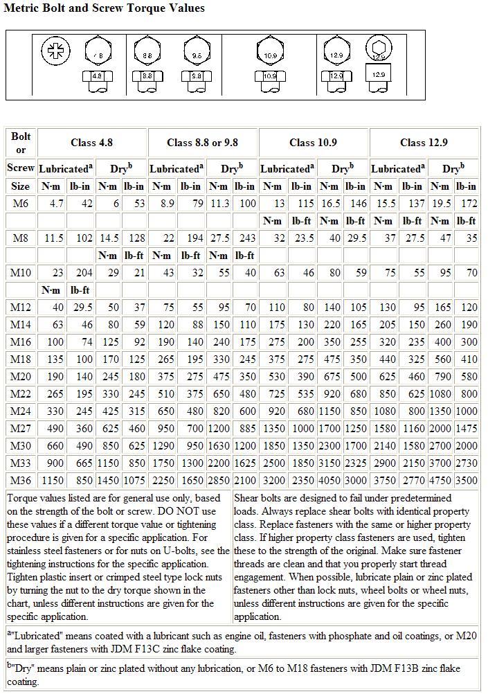
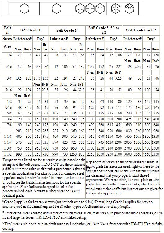
5 Table of Contents Section Page Warranty Statement... 2 Intended Use... 3 Table of Contents Ballasting... 6 Suitcase Weight Installation Bumper Clearance Height Adjustment Weight Rack Handling Bumper Installation 14 Bolt Torque Value Chart Installation Instructions Repair Parts
6 Ballasting IMPORTANT: Proper ballasting will keep efficiency of the four-wheel drive system and steering function when braking. IMPORTANT: Always put same amount of weight plates inside left and right hand weight carrier when using the Standard Bumper. Refer to 8000 Series SPFH Operator Manual for information regarding weight plate installation. IMPORTANT: Do not overload rear tires, especially when header is removed. IMPORTANT: Special field conditions may require higher ballasting to keep efficiency of the four-wheel drive system and steering function. Depending on machine/header type configurations, ballasting differs. To properly ballast the machine, ALWAYS refer to the relevant ballasting chart, then install required amount of weight. IMPORTANT: For the 7000-Series SPFH, refer to the Operator Manual for the SPFH and account for the weight of the bumper attachment in the same manner as rear, factory suitcase weights Series SPFH Field Operation Ballasting Chart The following ballasting charts for field operations are only recommendations. Keep in mind to ballast the machine so that the four-wheel drive system and steering function are ensured. Install required amount of weight plates or suitcase-type weights, depending on the style of bumper installed. 6
7 Base Bundle (Base bumper only; no weight rack) RC Ballasting Chart Field Operation Moderate Conditions Harvesting Unit 8100, 8200 Nb of weight plates on each side 8300 Nb of weight plates on each side 8400, 8500 Nb of weight plates on each side 8600 Nb of weight plates on each side 8700, 8800 Nb of weight plates on each side 639 Pickup Pickup Pickup ProfiCut 0 0 NR NR NR 620 ProfiCut NA NA /676 RHU 3 2 NR NR NR 460+/778 RHU : : 3 3 NR 475+/770+ RHU NA NA 8400:NA 8500: /696+ RHU 3 2 NR NR NR 360+/698+ RHU NR 375+/690+ RHU NR NR Notes: A. Values indicate number of plates to be used on the base machine. B. These plates are available through the John Deere parts system. C. NR = Not Recommended D. NA = Not Applicable E. RHU = Rotary Harvesting Unit F. Suitcase weights are not compatible with the Base Bundle. This is a bundle for a bumper only. G. All configurations without header support wheel option. 7
8 Base Bundle (Continued) (Base bumper only; no weight rack) RC Ballasting Chart Field Operation Hilly/Wet Conditions Harvesting Unit 8100, 8200 Nb of weight plates on each side 8300 Nb of weight plates on each side 8400, 8500 Nb of weight plates on each side 8600 Nb of weight plates on each side 8700, 8800 Nb of weight plates on each side 639 Pickup Pickup Pickup ProfiCut 0 0 NR NR NR 620 ProfiCut NA NA /676 RHU 4 4 NR NR NR 460+/778 RHU NR 475+/770+ RHU NA NA 8400: NA 8500: /696+ RHU 6 4 NR NR NR 360+/698+ RHU NR 375+/690+ RHU NA NR Notes: A. Values indicate number of plates to be used on the base machine. B. These plates are available through the John Deere parts system. C. NR = Not Recommended D. NA = Not Applicable E. RHU = Rotary Harvesting Unit F. Suitcase weights are not compatible with the Base Bundle. This is a bundle for a bumper only. G. All configurations without header support wheel option. 8
9 Standard Weight Rack RC Ballasting Chart Field Operation Moderate Conditions Harvesting Unit 8100, 8200 total weight to add 8300 total weight to add 8400, 8500 total weight to add 8600 total weight to add 8700, 8800 weight to add 639 Pickup Remove Remove Remove Remove Remove 649 Pickup Remove Remove Remove Remove Remove 659 Pickup Remove Remove Remove Remove Remove 480 ProfiCut Remove Remove NR NR NR 620 ProfiCut NA NA Remove Remove Remove 445+/676 RHU 0 0 NR NR NR 460+/778 RHU NR 475+/770+ RHU 345+/696+ RHU 360+/698+ RHU 375+/690+ RHU NA NA 8400:NA 8500: NR NR NR NR NA NA Notes: A. Values indicate total weight to be added to Weight Rack. B. No plates are to be used in the base machine. C. Suitcase weights to be evenly distributed on the weight rack. D. NR = Not Recommended E. NA = Not Applicable F. RHU = Rotary Harvesting Unit G. Remove = Remove weight rack and install bumper plate on base machine (no weights needed and weight rack to be removed to reduce weight) H. All configurations without header support wheel option. 9
10 Standard Weight Rack (Continued) RC Ballasting Chart Field Operation Hilly/Wet Conditions Harvesting Unit 8100, 8200 total weight to add 8300 total weight to add 8400, 8500 total weight to add 8600 total weight to add 8700, 8800 weight to add 639 Pickup Remove Remove Remove Remove Remove 649 Pickup Remove Remove Remove Remove Remove 659 Pickup NR NR Remove Remove Remove 480 ProfiCut Remove Remove NR NR NR 620 ProfiCut NA NA Remove Remove Remove 445+/676 RHU NR NR NR 460+/778 RHU NR 475+/770+ RHU 345+/696+ RHU 360+/698+ RHU 375+/690+ RHU Notes: NA NA 8400: NR 8500: NR NR NR : NR 8500: NR NA NA A. Values indicate total weight to be added to Weight Rack. B. No plates are to be used in the base machine. C. Suitcase weights to be evenly distributed on the weight rack. D. NR = Not Recommended E. NA = Not Applicable F. RHU = Rotary Harvesting Unit G. Remove = Remove weight rack and install bumper plate on base machine (no weights needed and weight rack to be removed to reduce weight) H. All configurations without header support wheel option. NR NR 10
 (104 lbs; 47.")
11 Suitcase Weight Installation All current standard tractor suitcase weights from John Deere should fit either weight rack. The most common part numbers of weights are as follows: R L38450 (95 lbs: 43 kg) (104 lbs; 47.4 kg) When an odd number of suitcase weights are used, place the last suitcase weight on the RH side of the machine to offset the weight of the drives of the header and feedrolls. IMPORTANT: Always install weights on the weight rack before installing the rack on the machine for ease of access to hardware. Always install weights towards the front of the rack. Standard Weight Rack Install weights on rack towards the front of the rack. Secure with threaded rod and jam nuts provided. See Figure 1. Figure 1. Standard Weight Rack Weight Installation Key 1 Suitcase Weight Key 2 Threaded Rod and Jam Nuts (provided) 11

12 Bumper Clearance Height Adjustment Bumper Adjustment The rubber stops of the bumper can be adjusted to decrease ground clearance as desired by the operator. To adjust the ground clearance, first remove the hardware for the rubber bumpers and the side bolts. Move the side rails down to a desired position. Reinstall side bolts at the highest and lowest holes possible containing both parts (4 places per side) Install the rubber stops to match the range of positions that customers trucks or other equipment may need. This is typically the highest and lowest position of the sliding rail, or about 5 (150 mm) apart. Tighten all hardware properly, but do not overtighten the hardware for the rubber stops as damage may occur. See Figure 2. Figure 2. Bumper Adjustment Key 1 Rubber Stop Key 2 Side Rail Key 3 Side Rail Hardware 12

13 Weight Rack Handling There are two different methods available to lift the weight rack into place on the machine: chains with lift mechanism or forklift. IMPORTANT: ALWAYS USE APPROPRIATE EQUIPMENT AND MEASURES WHEN LIFTING WEIGHT RACKS INTO POSITION OR SERIOUS INJURY MAY RESULT. Chain Method for Lifting Three hook points are provided on each weight rack for installation of chains. See Figures 3 and 4. Secure chains properly to hooks provided. Safely lift weight rack and bumper assembly into place. Install 8 of the ¾ x 2 Gr.8 Bolts with Lock Washers, and washers to the weld nuts in the weight rack. Tighten all hardware properly. Figure 3. Chain Method Key 1 Front Hook (center) Key 2 Rear Hooks (at back plate) Pintle Hitch Use Effective with s/n 1135, a pintle hitch replaces the bar at the rear of the bumper. Effective with s/n 1163, bumpers are equipped with both a bar and a pintle hitch. This pintle hitch is only intended for quick connections for a tow strap or chain. IMPORTANT: DO NOT USE THE PINTLE HITCH FOR PULLING ANY TRAILERS OR OTHER DEVICES AS MACHINE DAMAGE AND/OR INJURY MAY RESULT. See Figure 4. Figure 4. Pintle Hitch Location Key 1 Pintle Hitch 13

14 Forklift Method for Lifting Forklift fork holes are provided for lifting the weight rack by the use of a forklift. Align forks with the holes in the weight rack. Take care during handling to not protrude past the end of the assembly and damage other components on the base machine. Safely lift weight rack and bumper assembly into place. Install 8 of the ¾ x 2 Gr.8 Bolts with Lock Washers, and washers to the weld nuts in the weight rack. Tighten all hardware properly. Figure 5. Forklift Method Key 1 Forklift Fork Holes Key 2 Forklift Fork (ref) See Figure 5. Bumper Installation If a weight rack is not used, the bumper can be installed directly on the base plate. Use a lifting device to lift the bumper into position. Then secure bumper to base plate using 8 of the ¾ x 2 Gr.8 Bolts with Lock Washers, and washers to the weld nuts in the base plate. See Figure 6. Figure 6. Bumper Installation Key 1 Bumper Assembly Key 2 Base Plate Key 3 Bolt Location 14
15 15
16 16

17 Installation Instructions for 8000-Series SPFH 1.0 Preparing the Machine 1.1 Park Machine Park machine on a flat, hard surface. Set Park Brake. Lower header to the ground. Remove key from ignition. 1.2 Remove Hitch and Strap. Remove the Hitch Plate and Strap from the rear of the machine. See Figure Open access panel. Figure 7. Rear of Machine Key 1 Hitch Plate Key 2 - Strap Open rear door and remove cover at top of main frame. Set to side and take care to not damage the alarm. See Figure 8. Figure 8. Access Panel Removal Key 1 Access Panel Key 2 - Alarm 17
 ¾ x 2-1/4 Bolts, four (4) on top, four (4) on bottom, from the weight rack or bumper plate at the base plate. See Figure 9. 2.2 Loosen hardware on base plate Loosen all hardware remaining on base plate to make it easier to install the base plate on the machine.")
 Key 3 Support Hardware Key 4 Supports 18")
18 2.0 Preparing the Attachment 2.1 Remove the base plate from the attachment. Support the base plate at the lift holes and/or at the holes in the adapter brackets as indicated in Figure 5. Remove the eight (8) ¾ x 2-1/4 Bolts, four (4) on top, four (4) on bottom, from the weight rack or bumper plate at the base plate. See Figure Loosen hardware on base plate Loosen all hardware remaining on base plate to make it easier to install the base plate on the machine. Figure 9. Base Plate Removal Key 1 Base Plate Key 2 ¾ Bolts Key 3 Adapter Holes Key 4 Lift Hole If installing a standard weight rack, remove bag of hardware from back of base plate adapter. See Figure 10. Figure 10. Base Plate Hardware Key 1 Hardware Locations Key 2 Base Plate (Reference Only) Key 3 Support Hardware Key 4 Supports 18


19 3.0 Install Base Plate 3.1 Install base plate on machine by lifting the base plate with a lifting device at the chain holes. 3.2 Align the loose adapter brackets with the holes in the rear plate of the main frame of the base machine as shown in Fig. 11. IMPORTANT: Remember to keep all hardware loose for ease of assembly. 3.3 Inspect weld nuts on main frame or debris before installation to prevent damage. It may be beneficial to turn a M24 tap through each hole to make sure the threads are clean before installing the hardware. Install the M24 x 50 Bolts, Lock Washers, and Washers in the holes, but only hand tighten. Figure 11. Base Plate Install Key 1 Main Frame (ref) Key 2 Base Plate Key 3 Lift Holes Key 4 Main Frame Holes (qty 6) Key 5 M24 Bolt Locations (qty 6) 3.4 Install the provided 5/8 x2 Gr. 8 Bolts, Lock Washers, Washers, and Nuts at all frame locations in the center of the adapter (6 places) IMPORTANT: DO NOT TIGHTEN HARDWARE AT THIS TIME. ONLY HAND TIGHTEN. 3.5 Install the provided 5/8 x2 Gr. 8 Bolts, Lock Washers, Washers, and Nuts at the bottom support to the original mounting location for the hitch plate. Figure 12. Bottom Support Bolts Image for reference only. Key 1 Bolt Locations IMPORTANT: If unable to reach from the top access hole to install the nuts on bolts at Key 4 of Figure 12, remove the bottom support (shown in Figure 13) and access the bolt locations through the hole in the mainframe. Reinstall the bottom support after the hardware at Key 4 of Figure 11 is installed. See Figure
. D.")
20 3.6 Tighten all hardware in sequence as follows: A. Snug all hardware so all components are aligned properly. B. Tighten center bolts on rear of main frame (qty 6). See IMPORTANT note on Page 19 if unable to access this hardware and tighten before the bottom support is installed. C. Tighten M24 bolts at main frame (qty 6). D. Tighten 5/8 bolts at base plate (qty 4). E. Tighten bottom support bolts at hitch mount (qty 4). F. Tighten bottom support bolts at base plate (qty 10; 4 in center). Tighten all hardware properly. See Figure 13. Figure 13. Bolt Tightening Sequence Key A Base Plate (reference) Key B Main Frame Center Bolts Key C M24 Bolts Key D Base Plate Bolts Key E Hitch Mount Bolts Key F Bottom Support Bolts 3.7. Reinstall Cover Reinstall cover at top of main frame of base machine. Take care to not damage the alarm. See Figure 14. Figure 14. Access Panel Installation Key 1 Access Panel Key 2 Alarm NOTE: If installing only the bumper and not a weight rack, proceed to Section 5.0 Bumper Installation. 20
21 4.0 Install Weight Rack There are two different methods available to lift the weight rack into place on the machine: chains with lift mechanism or forklift. IMPORTANT: ALWAYS USE APPROPRIATE EQUIPMENT AND MEASURES WHEN LIFTING WEIGHT RACKS INTO POSITION OR SERIOUS INJURY MAY RESULT. 4.1 Chain Method For Lifting Three hook points are provided on each weight rack for installation of chains. See Figure 15. Secure chains properly to hooks provided. Safely lift weight rack and bumper assembly into place. Figure 15. Chain Method Key 1 Front Hook (center) Key 2 Rear Hooks (at back plate) Install 8 of the ¾ x 2 Gr.8 Bolts with Lock Washers, and washers to the weld nuts in the weight rack. Tighten all hardware properly. 21

22 4.2 Forklift Method for Lifting Forklift fork holes are provided for lifting the weight rack by the use of a forklift. Align forks with the holes in the weight rack. Take care during handling to not protrude past the end of the assembly and damage other components on the base machine. Safely lift weight rack and bumper assembly into place. Install 8 of the ¾ x 2 Gr.8 Bolts with Lock Washers, and washers to the weld nuts in the weight rack. Figure 16. Forklift Method Key 1 Forklift Fork Holes Key 2 Forklift Fork (ref) Tighten all hardware properly. See Figure Bumper Installation If a weight rack is not used, the bumper can be installed directly on the base plate. Use a lifting device to lift the bumper into position. Then secure bumper to base plate using 8 of the ¾ x 2 Gr.8 Bolts with Lock Washers, and washers to the weld nuts in the base plate. See Figure 17. Figure 17. Bumper Installation Key 1 Bumper Assembly Key 2 Base Plate Key 3 Bolt Location 22

23 5.1 Bumper Adjustment The rubber stops of the bumper can be adjusted to decrease ground clearance as desired by the operator. To adjust the ground clearance, first remove the hardware for the rubber bumpers and the side bolts. Move the side rails down to a desired position. Reinstall side bolts at the highest and lowest holes possible containing both parts (4 places per side) Install the rubber stops as desired on the Side Rail. Bumpers can be spaced apart or together, to accommodate different bumper heights of trucks as needed. Effective with s/n 1163, 6 bumpers are used. They can be spaced as desired. Figure 18. Bumper Adjustment Key 1 Rubber Stop Key 2 Side Rail Key 3 Side Rail Hardware Tighten all hardware properly, but do not overtighten the hardware for the rubber stops as damage may occur. See Figure 18. Note: Effective with s/n 1135, two additional rubber bumpers are added to the design. Also, the bar at the rear is replaced with a pintle hitch. Additional holes are provided for the pintle hitch. If adding these components to previous bumpers, additional holes will need to be drilled in the base plate for the pintle hitch. The additional bumpers can be added using two (2) new RC Plates for mounting. See Figure 19. Figure 19. Bumper Updates Key 1 Pintle Hitch Key 2 Additional Bumper Key 3 RC Plate 23
24 Installation Instructions For 7000-Series SPFH Installation of the bundle is nearly the same as for an 8000-Series SPFH, with a few exceptions. The vertical supports and lower support frame are not used with the 7000-SPFH. However, additional hardware is used on the base plate for mounting to the rear of the SPFH. See Figure 20 for an illustration of the extra parts provided. Refer to Parts Pages for more information. Additional holes are provided at the sides of the base plate. Hardware is provided. These METRIC bolts are used with AND without an in-frame tank. They are full-thread such that they can be used with or without spacer plates as described below. They are metric to match the hardware used for the in-frame tank mounts. If using an in-frame inoculant tank, 4 John Deere plate weights (Z48791) are needed as a spacer to allow the base of the bumper to clear the brackets supporting the tank. Longer bolts are provided with the RCI bundle to account for the increased mounting distance needed. Scrap any unused hardware after installation. Figure 20. Extra Parts Provided Key A Side Mounting METRIC Bolts Key B Hitch Spacer Plate Refer to text at left for more information. If an in-frame inoculant tank is used, the hitch plate cannot mount to the frame of the SPFH. To mount a hitch plate, the weight rack bundle from RCI must be used. If no tank is used, the hitch plate will mount to the original mounting location of the SPFH when the RCI weight rack is not used. A spacer is required, along with longer hardware. This is provided in the RCI bundle. If an RCI weight rack is used, the spacer will not be needed and can be scrapped. Longer bolts are provided as extra with the spacer. Any unused hardware should also be scrapped after installation. 24
25 REPAIR PARTS General Comments The following includes information regarding parts for the Bumper Attachment. Right or left hand parts are determined by sitting in the operator s seat facing forward. The abbreviation A.R. in the USED column indicates As Required. This is because a different number of the specific component may be needed for proper assembly depending on the tolerance of the individual machine. All parts listed for the Bumper Attachment are available through your local dealer. Attention: Dealer Contact RCI directly for all part orders for this attachment. In general, any fabricated component painted black is an RCI part and any part that is painted John Deere green is a John Deere part and can be located in the Parts Manual for the machine to which the attachment is installed. Please include a serial number and model of the attachment when placing a parts order. The serial number plate is attached to the rear plate of the belt frame. Replacement Hardware The use of improper hardware in any location can result in the failure of the component fastened with the hardware or related structures, and can cause personal injury, further damage to the product, or loss of property. Replacement Parts Replacement parts may have occasional differences to the parts being replaced. This difference is typically providing the benefit of a design change made after the release of this publication. 25
26 Repair Parts Alphabetical Index 8000-SPFH Base Bundle SPFH Base Bundle Standard Weight Rack
27 8000-SPFH Base Bundle 27
28 8000-SPFH Base Bundle Key Part Number Description QTY Comments 1 RC Frame, Mount 1 2 RC Support, Right 1 3 RC Support, Left 1 4 RC Support, Bottom 1 5 RC Washer, 3/4 SAE YZ Flat 36 6 RC Washer, 3/4, Lock 8 7 RC Bolt, 3/4-10 x 2-1/4 Gr 8 YZ Hex 22 8 RC Bolt, M x 55mm 6 9 RC Washer, 1 SAE YZ Flat 6 10 RC Washer, M24 Lock 6 11 RC Nut, 3/4-10 Gr 8 Nylock RC Bolt, 5/8-11 X 2.0 GR8 Hex RC Washer, 5/8 SAE YZ Flat RC Nut, 5/8-11 YZ Nylock RC Bumper 6 16 RC Plate, Bumper Adjuster 2 17 RC Hitch, Pintle 1 Use hardware provided 18 RC Bolt, 5/8-11 x 3-1/4" GR8 Hex RC Weldment, Front Plate 1 20 RC Bracket, Bar 1 21 RC Pin 1 22 RC Pin, 1/2 x 3.0" CZ Square Retainer 1 28
29 7000-SPFH Base Bundle 29
30 7000-SPFH Base Bundle Key Part Number Description QTY Comments 1 RC Weldment, Frame Mount 1 2 RC Assembly, Backplate 1 3 RC Weldment, Hitch Plate Spacer 1 A 4 RC Bolt, 5/8-11 x 2-1/2 Gr 8 YZ Hex 8 B 5 RC Bolt, 5/8-11 x 4-1/4 Gr 8 YZ Hex 12 C 6 RC Washer, 5/8 SAE YZ Hard Flat 24 7 RC Nut, 5/8-11 YZ Nylock 12 8 RC Bolt, 3/4-10 x 2-1/4 Gr 8 YZ Hex 8 9 RC Washer, 3/4 SAE YZ Flat 8 10 RC Washer, 3/4 YZ Lock 8 11 RC Bolt, M x 100 Gr10.9 YZ Tap 6 D 12 RC Washer, M12 YZ Hard Flat RC Washer, M12 YZ Lock 6 14 RC Nut, M YZ Hex 6 15 Deere Part Plate, Hitch E A - For use without tank kit or Standard bundle B - For use without tank kit C - For use with tank kit D - If tank kit installed, bottom two bolts thread into tank support E - Used from base machine, unless tank kit installed 30
31 Standard Weight Rack Key Part Number Description QTY Comments 1 RC Weldment, Standard Bumper 1 2 RC Nut, 3/4-10 YZ Jam 8 3 RC Rod, 3/4-10 x 14 Threaded 2 4 RC Washer, 3/4 USS 4 5 RC Bolt, 3/4-10 x 2-1/4 Gr 8 YZ Hex 16 6 RC Washer, 3/4, Lock 16 7 RC Washer, 3/4 SAE YZ Flat 16 31
32 208 River Knoll Drive Mayville, WI Fax
Operator Manual. Includes operating, adjustment, maintenance, technical, repair parts, and safety instructions for the 8A Bumper Attachment.
 8A BUMPER ATTACHMENT Operator Manual Includes operating, adjustment, maintenance, technical, repair parts, and safety instructions for the 8A Bumper Attachment. Please retain this document for future reference.
8A Bumper Attachment 17 October Series and 8000-Series SPFH
 8A Bumper Attachment 17 October 2017 7000-Series and 8000-Series SPFH The 8A Bumper Attachment is available from RCI Engineering for the John Deere 7000- and 8000-Series Self-Propelled Forage Harvesters.
Draper Platform Adaptation Bundle
 Draper Platform Adaptation Bundle 7050-Series Self-Propelled Forage Harvester 900D-Series Draper Platform RC042050 Operator s Manual Includes installation, operating, adjustment, technical, repair parts
Operator Manual 812A COMBINE HEADER ADAPTER
 812A COMBINE HEADER ADAPTER Operator Manual Includes operating, adjustment, maintenance, technical, repair parts, and safety instructions for the 812A Combine Header Adapter Attachment. Please retain this
96A Windrow Pickup Attachment For John Deere Model 3975 Pull-Type Forage Harvester. Operator's Manual
 96A Windrow Pickup Attachment For John Deere Model 3975 Pull-Type Forage Harvester Operator's Manual Includes installation, operating, adjustment, maintenance, technical, repair parts and safety instructions
186M Windrow Merger. Operator Manual
 186M Windrow Merger Operator Manual Includes operating, adjustment, maintenance, technical, repair parts and safety instructions for the 186M Windrow Merger. Please retain this document for future reference.
Installation / Owners Manual
 DEALER/INSTALLER: (1) Provide this Manual to end user END USER: Part Number: 94621 94622* *Packaged for Individual sale. (1) Read and follow this Manual for Reese Installation. (2) Save this Manual for
31075 INSTALLATION INSTRUCTIONS
 075 INSTALLATION INSTRUCTIONS Safety glasses should be worn at all times while installing this product. YEARS: 06-PRESENT MAKE: TOYOTA MODEL: TACOMA STYLE: PICKUP WARNING: NEVER EXCEED YOUR VEHICLE MANUFACTURER'S
13102 INSTALLATION INSTRUCTIONS
 1310 INSTALLATION INSTRUCTIONS Safety glasses should be worn at all times while installing this product. YEARS: 010-PRESENT MAKE: MERCEDES BENZ MODEL: ML350 BlueTEC, GL350 BlueTEC AWD, GL50, & GL550 STYLE:
15802 INSTALLATION INSTRUCTIONS
 0 INSTALLATION INSTRUCTIONS Safety glasses should be worn at all times while installing this product. YEARS: 0-PRESENT MAKE: FORD MODEL: F-0, F-0, F-0 STYLE: PICKUP WARNING: NEVER EXCEED YOUR VEHICLE MANUFACTURER'S
LIMITED WARRANTY DISCLAIMER OF IMPLIED WARRANTIES & CONSEQUENTIAL DAMAGES
 Published 08/15 LIMITED WARRANTY Bush Hog warrants to the original purchaser of any new Bush Hog equipment, purchased from an authorized Bush Hog dealer, that the equipment be free from defects in material
Please visit for the latest version of these installation instructions.
 Please visit www.blueox.com for the latest version of these installation instructions. DH2400 (Long & Standard Box) Please read these in their entirety prior to installing or operating this equipment.
Please visit for the latest version of these installation instructions.
 Please visit www.blueox.com for the latest version of these installation instructions. 2014-2017 Ram 2500 (All beds) Please read these in their entirety prior to installing or operating this equipment.
Installation Instructions
 Equipment Required: Installation Instructions Fastener Kit: F Wrenches: 15/16, 10 mm Drill Bits: 1/4 Other Tools: Drill, Reciprocating Saw 9464/9474 HIDE-A-GOOSE HITCH All Fasteners Typical, Both Sides
WARNING: NEVER EXCEED YOUR VEHICLE MANUFACTURER'S RECOMMENDED TOWING CAPACITY LBS. LBS.
 05 INSTALLATION INSTRUCTIONS Safety glasses should be worn at all times while installing this product. YEARS: 00-CURRENT MAKE: HONDA MODEL: INSIGHT STYLE: 5 DOOR WARNING: NEVER EXCEED YOUR VEHICLE MANUFACTURER'S
AGCO. Corn Header Manual d HEADSIGHT.COM
 AGCO Corn Header Manual 09020401d HEADSIGHT.COM 574.546.5022 About Headsight Headsight Contact Info Headsight, Inc. 4845 3B Road Bremen, IN 46506 Phone: 574-546-5022 Fax: 574-546-5760 Email: info@headsight.com
WARNING. Serial Number
 1999NS-2007 Chevrolet & GMC Pickup 1500 Classic (2WD & 4WD, No Heavy Duty) Please read BOTH these Installation Instructions and the Baseplate General Towing Instructions before attempting to install or
Installation Instructions READ THOROUGHLY BEFORE BEGINNING Signature Series Rail Kit Dodge Ram Trucks-all, including Mega-cabs
 INDEX Failure to follow all of these instructions may result in death or serious injury!. GUIDELINES FOR MATCHING TOW VEHICLE AND TRAILER. Pages -. DRILLED AND BOLTED INSTALLATION FIGURE. Page 4. NO-DRILL,
GERINGHOFF. Corn Header Manual f HEADSIGHT.COM
 GERINGHOFF Corn Header Manual 09020701f HEADSIGHT.COM 574.546.5022 About Headsight Headsight Contact Info Headsight, Inc. 4845 3B Road Bremen, IN 46506 Phone: 574-546-5022 Fax: 574-546-5760 Email: info@headsight.com
Installation Instructions
 Installation Instructions CUSTOM QUICK INSTALL MOUNTING KIT 2011 & UP Ford Super Duty F-250/F-350/F-50 2011 & UP Part Number: 50073 WARNING: Under no circumstances do we recommend exceeding the towing
11309 INSTALLATION INSTRUCTIONS
 09 INSTALLATION INSTRUCTIONS Safety glasses should be worn at all times while installing this product. YEARS: 0-PRESENT MAKE: NISSAN MODEL: LEAF STYLE: -DOOR WARNING: NEVER EXCEED YOUR VEHICLE MANUFACTURER'S
31087 INSTALLATION INSTRUCTIONS
 31087 INSTALLATION INSTRUCTIONS Safety glasses should be worn at all times while installing this product. YEARS: 019-PRESENT MAKE: RAM MODEL: 1500 STYLE: TRUCK WARNING: NEVER EXCEED YOUR VEHICLE MANUFACTURER'S
Installation Instructions
 Equipment Required: Fastener Kit: F Wrenches: 3/4, 15/16, 10mm, 18mm Drill Bits: 1/4 Other Tools: Drill, Reciprocating saw 9465/9475 HIDE-A-GOOSE HITCH INSTALLATION All Fasteners Typical, Both Sides WARNING:
INSTALLATION INSTRUCTIONS
 0 YEARS: 0-PRESENT Safety glasses should be worn at all times while installing this product. INSTALLATION INSTRUCTIONS MAKE: FORD MODEL: F-0 STYLE: TRUCK WARNING: NEVER EXCEED YOUR VEHICLE MANUFACTURER'S
INSTALLATION INSTRUCTIONS
 58 MAKE: HYUNDAI YEARS: 08-PRESENT Safety glasses should be worn at all times while installing this product. INSTALLATION INSTRUCTIONS MODEL: ACCENT STYLE: SEDAN WARNING: NEVER EXCEED YOUR VEHICLE MANUFACTURER'S
31015 INSTALLATION INSTRUCTIONS
 0 INSTALLATION INSTRUCTIONS Safety glasses should be worn at all times while installing this product. YEARS: 00-CURRENT MAKE: DODGE RAM MODEL: 00 STYLE: TRUCK WARNING: NEVER EXCEED YOUR VEHICLE MANUFACTURER'S
CORN HEADER MANUAL: CNH PRE-2012
 CORN HEADER MANUAL: CNH PRE-2012 09020201c HEADSIGHT.COM 574.546.5022 About Headsight Headsight Contact Info Headsight, Inc. 4845 3B Road Bremen, IN 46506 Phone: 574-546-5022 Fax: 574-546-5760 Email:
13233 INSTALLATION INSTRUCTIONS
 13233 INSTALLATION INSTRUCTIONS Safety glasses should be worn at all times while installing this product. YEARS: 2016-PRESENT MAKE: VOLVO MODEL: XC90 STYLE: SUV WARNING: NEVER EXCEED YOUR VEHICLE MANUFACTURER'S
13149 INSTALLATION INSTRUCTIONS
 39 INSTALLATION INSTRUCTIONS Safety glasses should be worn at all times while installing this product. YEARS: 006-CURRENT MAKE: TOYOTA MODEL: RAV (EXCEPT ELECTRIC) STYLE: COMPACT SUV WARNING: NEVER EXCEED
12108 INSTALLATION INSTRUCTIONS
 08 INSTALLATION INSTRUCTIONS Safety glasses should be worn at all times while installing this product. YEARS:006 - CURRENT MAKE: TOYOTA MODEL: RAV STYLE: COMPACT SUV WARNING: NEVER EXCEED YOUR VEHICLE
LIFT NAME PART NUMBER SETBACK (min) SETBACK (max)
 SETBACK (max)") Revolution 9889 Garrymore Ln Missoula, MT 59808 888-687-3552 +1-406-549-0769 www.aquacreek.com Wheelchair Attachment PART #: F-705S3 WEIGHT CAPACITY: 350 POUNDS - STANDARD REVOLUTION 300 POUNDS - DEEP
Revolution 9889 Garrymore Ln Missoula, MT 59808 888-687-3552 +1-406-549-0769 www.aquacreek.com Wheelchair Attachment PART #: F-705S3 WEIGHT CAPACITY: 350 POUNDS - STANDARD REVOLUTION 300 POUNDS - DEEP
DISC HARROW PART'S MANUAL DHP8/10/12. RHINO 1020 S. Sangamon Ave. Gibson City, IL
 DISC HARROW DHP8/10/12 Published 03/16 PART'S MANUAL P/N 00789085P An Operator's Manual was shipped with the equipment in the Manual Canister. This Operator's Manual is an integral part of the safe operation
31068 INSTALLATION INSTRUCTIONS
 0 INSTALLATION INSTRUCTIONS Safety glasses should be worn at all times while installing this product. YEARS: 009-CURRENT MAKE: FORD MODEL: F-0 STYLE: ALL WARNING: NEVER EXCEED YOUR VEHICLE MANUFACTURER'S
Installation Instructions **THIS RAIL MOUNTING KIT USES 11 BOLTS**
 Installation Instructions CUSTOM QUICK INSTALL MOUNTING KIT FORD SUPER DUTY Part Numbers: 50074 WARNING:Under no circumstances do we recommend exceeding the towing vehicle manufacturers recommended vehicle
Installation Instructions
 9049 Tyler Blvd. Mentor, Ohio 44060 Phone (440) 974-8888 Fax (440) 974-0165 Toll-Free Fax 800-841-8003 saltdogg.com TGS06 Salt Spreader Installation Instructions Safety Precautions WARNING Observe the
11529 INSTALLATION INSTRUCTIONS
 11529 INSTALLATION INSTRUCTIONS Safety glasses should be worn at all times while installing this product. YEARS: 2018-PRESENT MAKE: HYUNDAI MODEL: KONA STYLE: SUV WARNING: NEVER EXCEED YOUR VEHICLE MANUFACTURER'S
INSTALLATION INSTRUCTIONS
 08 YEARS: 07-CURRENT Safety glasses should be worn at all times while installing this product. INSTALLATION INSTRUCTIONS MODEL: RIDGELINE MAKE: HONDA STYLE: TRUCK WARNING: NEVER EXCEED YOUR VEHICLE MANUFACTURER'S
5000 SERIES STALK DEVASTATOR CORN STALK ROLLER
 5000 SERIES STALK DEVASTATOR CORN STALK ROLLER *PATENTED* 5000-025A, 5000-026A, 5000-027A, 5000-028A, 5000-034A John Deere Model Corn Heads (606C, 643, 693, 706C, 608C, 843, 893, 708C, 612C, 612FC Folding,
metric BOlTS: 42 ft/lbs.
 Subaru Outback 11-13 TP20272,Rev.1 BOlT TORQuE SPECIfICATIONS STANDARD BOlTS: Size grade Torque 5/16 5 20 ft/lbs. 3/8 5 35 ft/lbs. 7/16 5 56 ft/lbs. 1/2 5 85 ft/lbs. metric BOlTS: Size 8mm 10mm 12mm 14mm
Installation Instructions
 Equipment Required: Fastener Kit: F Wrenches: 15/16, 10 mm Drill Bits: 1/4 Other Tools: Drill, Reciprocating Saw 9464/9474 HIDE-A-GOOSE HITCH INSTALLATION All Fasteners Typical, Both Sides WARNING: Under
13163 INSTALLATION INSTRUCTIONS
 INSTALLATION INSTRUCTIONS Safety glasses should be worn at all times while installing this product. YEARS: 0-CURRENT MAKE: MITSUBISHI MODEL: OUTLANDER STYLE: SUV WARNING: NEVER EXCEED YOUR VEHICLE MANUFACTURER'S
metric BOlTS: 42 ft/lbs.
 Nissan Sentra 04-10 TP20276,Rev.0 Pin height - 12-1/2 Centers - 20-1/2 BOlT TORQuE SPECIfICATIONS STANDARD BOlTS: Size grade Torque 5/16 5 20 ft/lbs. 3/8 5 35 ft/lbs. 7/16 5 56 ft/lbs. 1/2 5 85 ft/lbs.
13541 INSTALLATION INSTRUCTIONS
 354 INSTALLATION INSTRUCTIONS Safety glasses should be worn at all times while installing this product. YEARS: 00-PRESENT MAKE: LEXUS MODEL: RX350 & RX450H STYLE: CROSSOVER SUV WARNING: NEVER EXCEED YOUR
PIVOTING TANDEM CARRIER 558P
 K PIVOTING TANDEM CARRIER 558P PARTS INCLUDED C A D I B D I G E J F part description part number qty. A front beam 1 B tail beam 1 C detent pin and tether 8535259 2 D wheel strap assembly 8535260 2 E handlebar
13136 INSTALLATION INSTRUCTIONS
 INSTALLATION INSTRUCTIONS Safety glasses should be worn at all times while installing this product. YEARS: 09-PRESENT MAKE: AUDI/PORSCHE MODEL: Q/MACAN (EXCLUDING HYBRID) STYLE: SUV WARNING: NEVER EXCEED
11381 INSTALLATION INSTRUCTIONS
 INSTALLATION INSTRUCTIONS Safety glasses should be worn at all times while installing this product. YEARS: 0-CURRENT MAKE: BMW MODEL: -SERIES STYLE: SEDAN WARNING: NEVER EXCEED YOUR VEHICLE MANUFACTURER'S
MODELS EWR820, EWR1023, EWR1227 PULL TYPE HAY RAKES PARTS MANUAL SECTION 19
 EWR MODELS EWR820, EWR1023, EWR1227 PULL TYPE HAY RAKES Published 04/11 PARTS MANUAL SECTION 19 MATERIAL HANDLING PARTS MANUAL PARTS ORDERING GUIDE The following instructions are offered to help eliminate
Complete Raised Rail Roof Rack System SR1098 SR1099
 Complete Raised Rail Roof Rack System SR1098 SR1099 7 kg/15 lbs xx kg xx lbs Max. 68 kg/150 lbs Instructions Max load capacity 68 kg/150 lbs Before you begin, please read the assembly instructions carefully.
31033 INSTALLATION INSTRUCTIONS
 10 INSTALLATION INSTRUCTIONS Safety glasses should be worn at all times while installing this product. YEARS: 011-PRESENT MAKE: JEEP / DODGE MODEL: GRAND CHEROKEE / DURANGO STYLE: SUV WARNING: NEVER EXCEED
13143 INSTALLATION INSTRUCTIONS
 13143 INSTALLATION INSTRUCTIONS Safety glasses should be worn at all times while installing this product. YEARS: 2010-PRESENT MAKE: LEXUS MODEL: RX 350 (INCLUDING F SPORT) & RX 450H STYLE: CROSSOVER SUV
OWNER'S MANUAL L A W N R O L L E R PRT-481S BH. Safety Assembly Operation Repair Parts Maintenance. Visit us on the web!
 OWNER'S MANUAL L A W N R O L L E R ROLLER MODEL: PRC- BH PRT- BH PRT-S BH PRT-S BH Safety Assembly Operation Repair Parts Maintenance Recommended for use with Riding Mowers, Lawn or Garden Tractors, and
INSTALLATION INSTRUCTIONS MOUNTING KIT FOR ELITE SERIES
 INSTALLATION INSTRUCTIONS MOUNTING KIT FOR ELITE SERIES DEALER/INSTALLER: (1) Provide this Manual to end user. END USER: (1) Save this Manual for future reference. (2) Pass on copies of Manual to any other
Installation Instructions SRC Over-Size Tire Carrier Jeep Wrangler/Unlimited Part # 2743
 NOTE: Carefully read instructions entirely before assembling/installing this product. Parts Included Qty Parts Included Qty Tire Carrier 1 8 x 70mm Hex Bolt 4 Brake Light Bracket 1 8mm Flat Washer 4 Tire
INSTALLATION INSTRUCTIONS
 YEARS: 05-PRESENT Safety glasses should be worn at all times while installing this product. INSTALLATION INSTRUCTIONS MAKE: FORD MODEL: EDGE STYLE: SUV WARNING: NEVER EXCEED YOUR VEHICLE MANUFACTURER'S
INSTALLATION INSTRUCTIONS
 119 YEARS: 01-PRESENT Safety glasses should be worn at all times while installing this product. INSTALLATION INSTRUCTIONS MODEL: SORENTO MAKE: KIA STYLE: SUV WARNING: NEVER EXCEED YOUR VEHICLE MANUFACTURER'S
Please visit for the latest version of these installation instructions.
 Please visit www.blueox.com for the latest version of these installation instructions. BX1139 2018 Jeep Wrangler / Wrangler Unlimited (JL) (All Models w/standard Bumper) Attachment Tab Height: 18 Serial
INSTALLATION INSTRUCTIONS
 0 YEARS: 0 Safety glasses should be worn at all times while installing this product. INSTALLATION INSTRUCTIONS MAKE: VOLKSWAGEN MODEL: JETTA TDI STYLE: SEDAN WARNING: NEVER EXCEED YOUR VEHICLE MANUFACTURER'S
MOUNTING RAILS ***DO NOT EXCEED VEHICLE MANUFACTURER'S RECOMMENDED TOWING CAPACITY.***
 10/30/2017 PAGE 1 OF 6 Parts List ITEM QTY PART NUMBER DESCRIPTION 1 2 CM-16150-MR MOUNTING RAILS 2 2 CM-16150-FB.375" FRONT BRACKET 3 1 CM-16150-PSRB.375" PASSENGER SIDE REAR BRACKET 4 1 CM-16150-DSRB.375"
INSTALLATION INSTRUCTIONS
 078 YEARS: 07-CURRENT Safety glasses should be worn at all times while installing this product. INSTALLATION INSTRUCTIONS MODEL: SUPER DUTY MAKE: FORD STYLE: TRUCK WARNING: NEVER EXCEED YOUR VEHICLE MANUFACTURER'S
LOWER EXHAUST FISHWIRE HARDWARE REQUIRED FASCIA & BRACKET TRIM REQUIRED
 3306 YEARS: 207 Safety glasses should be worn at all times while installing this product. INSTALLATION INSTRUCTIONS MAKE: HONDA MODEL: CR-V STYLE: SUV WARNING: NEVER EXCEED YOUR VEHICLE MANUFACTURER'S
ROTARY TILLER. Operation, Service & Parts Manual For "AS" Series. FORM: ASTillerBook.QXD
 ROTARY TILLER Operation, Service & Parts Manual For "AS" Series FORM: ASTillerBook.QXD April 2002 TABLE OF CONTENTS Preparation......................................1 Assembly Instructions.............................2
31033 INSTALLATION INSTRUCTIONS
 10 INSTALLATION INSTRUCTIONS Safety glasses should be worn at all times while installing this product. YEARS: 011-CURRENT MAKE: JEEP / DODGE MODEL: GRAND CHEROKEE / DURANGO STYLE: SUV WARNING: NEVER EXCEED
Deere G & GP Series Snow Wing Installation
 Deere G & GP Series Snow Wing Installation Model: Serial Number: Rev. 10/13 Rylind Manufacturing, Inc. 2801 Youngfield St Suite 250 Golden, CO 80401 Offices: 303-979-3548 Fax: 303-979-4730 www.rylind.com
11362 INSTALLATION INSTRUCTIONS
 116 INSTALLATION INSTRUCTIONS Safety glasses should be worn at all times while installing this product. YEARS: 01-PRESENT MAKE: LEXUS MODEL: ES 50 / ES 00h STYLE: SEDAN WARNING: NEVER EXCEED YOUR VEHICLE
Doing Our Best to Provide You the Best. Centers-25-3/4 Pin Height PARTS LIST BOLT TORQUE SPECIFICATIONS TP20076,Rev.
 11-08 TP20076,Rev.5 Ford F-150 Pick-Up (4WD) Ford Expedition (4WD) BOLT TORQUE SPECIFICATIONS STANDARD BOLTS: METRIC BOLTS: Size Grade Torque Size Torque 5/16 5 20 ft/lbs. 8mm 22 ft/lbs. /8 5 5 ft/lbs.
Please visit for the latest version of these installation instructions.
 Please visit www.blueox.com for the latest version of these installation instructions. Attachment Tab Height: 19-1/2 Serial Number Attachment Tab Width: 19 Please read BOTH these and the General Information
BMW X3 UNDERBODY PANEL TRIM DIAGRAM in
 13107 10/5/2012 BMW X3 PAGE 1 OF 2 GROSS LOAD CAPACITY WHEN USED AS A WEIGHT CARRYING HITCH: 3,500 LBS. TRAILER WEIGHT & 350 LBS. TONGUE WEIGHT. GROSS LOAD CAPACITY WHEN USED AS A WEIGHT DISTRIBUTION HITCH:
GROSS LOAD CAPACITY WHEN USED AS A WEIGHT CARRYING HITCH: 2,000 LBS. TRAILER WEIGHT & 200 LBS. TONGUE WEIGHT.
 PAGE 1 0F 6 GROSS LOAD CAPACITY WHEN USED AS A WEIGHT CARRYING HITCH: 2,000 LBS. TRAILER WEIGHT & 200 LBS. TONGUE WEIGHT. WARNING: ALL NON-TRAILER LOADS APPLIED TO THIS PRODUCT MUST BE SUPPORTED BY 18050
Rhino Long Travel Spindle Kit Yamaha Rhino FTR10072
 4331 EUCALYPTUS AVE. ~~ CHINO, CA 91710 909-597-7800 Fax 909-597-7185 Rhino Long Travel Spindle Kit 2005-08 Yamaha Rhino FTR10072 PARTS LIST: QTY. Part # Description 1 FTS95061D Rhino Spindle Driver 1
Installation Instructions
 Equipment Required: Installation Instructions Fastener Kit: F Wrenches: 3/4, 15/16 Drill Bits: 1/4 Other Tools: Drill WARNING: Under no circumstances do we recommend exceeding the towing vehicle manufacturers
INSTALLATION INSTRUCTIONS MOUNTING KIT GENERAL MOTORS Chevrolet Silverado/GMC Sierra 2500HD & 3500HD
 INSTALLATION INSTRUCTIONS MOUNTING KIT GENERAL MOTORS 2001-2006 Chevrolet Silverado/GMC Sierra 2500HD & 3500HD DEALER/INSTALLER: (1) Provide this Manual to end user. END USER: (1) Save this Manual for
12136 INSTALLATION INSTRUCTIONS
 6 INSTALLATION INSTRUCTIONS Safety glasses should be worn at all times while installing this product. YEARS: 0-PRESENT MAKE: SUBARU MODEL: OUTBACK STYLE: WAGON WARNING: NEVER EXCEED YOUR VEHICLE MANUFACTURER'S
12171 INSTALLATION INSTRUCTIONS
 1171 INSTALLATION INSTRUCTIONS Safety glasses should be worn at all times while installing this product. YEARS: 017-PRESENT MAKE: KIA MODEL: NIRO STYLE: CUV WARNING: NEVER EXCEED YOUR VEHICLE MANUFACTURER'S
31068 INSTALLATION INSTRUCTIONS
 31068 INSTALLATION INSTRUCTIONS YEARS: 009-CURRENT MAKE: FORD MODEL: EXPEDITION STYLE: SUV 009-CURRENT LINCOLN NAVIGATOR SUV 009-014 FORD F-150 TRUCK WARNING: NEVER EXCEED YOUR VEHICLE MANUFACTURER'S RECOMMENDED
Installation Instructions
 Part Numbers: ALL 5AB-XXXX DEALER/INSTALLER: (1) Provide this Manual to end user END USER: (1) Read and follow this Manual every time you use this product. PIN BOX SHOWN ASSEMBLED Equipment Required: Wrenches:
Installation Instructions
 Ford F250-F450 20K OE Series Industry Standard Adapter #4442 Industry Standard Super 5 th #1900 Gross Trailer Weight (Maximum) 16,000 lbs. Vertical Load Weight (Max. Pin Weight) 4,000 lbs. #2100 Gross
Installation Instructions
 Equipment Required: Fastener Kit: F Wrenches: 3/4, 15/16 Drill Bits: 1/4 Other Tools: Drill Short & Long Bed All Megacabs 9464/9474 HIDE-A-GOOSE HITCH INSTALLATION WARNING: Under no circumstances do we
Installation Instructions
 Equipment Required: Fastener Kit: F Wrenches: 3/4, 15/16 Drill Bits: 1/4 Other Tools: Drill, Reciprocating saw WARNING: Under no circumstances do we recommend exceeding the towing vehicle manufacturers
11221 INSTALLATION INSTRUCTIONS
 INSTALLATION INSTRUCTIONS Safety glasses should be worn at all times while installing this product. YEARS: 0-CURRENT MAKE: CHEVROLET MODEL: VOLT STYLE: SEDAN WARNING: NEVER EXCEED YOUR VEHICLE MANUFACTURER'S
Installation Instructions
 Equipment Required: Fastener Kit: F Wrenches: 15/16, 15/16 Crowfoot Adaptor Drill Bits: 1/4 Other Tools: Drill, Reciprocating saw Optional, Raise Bed: 18mm socket, 15 extension As an option you can loosen
Hollywood Racks Assembly & installation instructions for models:
 Hollywood Racks Assembly & installation instructions for models: HR1400Y (4 bike), HR1450Y (2 bike), HR1475Y, 1450Y-E & 1455Y-E (E bikes) For use on 2 hitches only. Do not use a 1 ¼ -2 hitch adapter. Maximum
INSTALLATION INSTRUCTIONS MOUNTING KIT FOR ELITE SERIES
 INSTALLATION INSTRUCTIONS MOUNTING KIT FOR ELITE SERIES DO NOT EXCEED VEHICLE MANUFACTURER S RATING FOR 5th WHEEL TOWING OR MAXIMUM GROSS TRAILER WEIGHT OF 18,000lb. / 8160kg. DEALER/INSTALLER: (1) Provide
13119 INSTALLATION INSTRUCTIONS
 9 INSTALLATION INSTRUCTIONS Safety glasses should be worn at all times while installing this product. YEARS: 0-PRESENT MAKE: HONDA MODEL: CR-V STYLE: SUV WARNING: NEVER EXCEED YOUR VEHICLE MANUFACTURER'S
Instruction Manual. ATV Manual Plow Lift
 Instruction Manual ATV Manual Plow Lift Manual Conventions This manual uses the following symbols to help differentiate between different kinds of information. The safety symbol is used with a key word
Rear Weight Kit M060
 Operator s Manual Rear Weight Kit 490-900-M060 WARNING READ AND FOLLOW ALL SAFETY RULES AND INSTRUCTIONS IN THIS MANUAL BEFORE ATTEMPTING TO OPERATE THIS MACHINE. FAILURE TO COMPLY WITH THESE INSTRUCTIONS
Doing Our Best to Provide You the Best. Toyota Tacoma. Pin height: 17 Centers: 30-1/2. BOlT TORQuE specifications TP20190,Rev 7
 10-13 TP20190,Rev 7 Toyota Tacoma BOlT TORQuE specifications standard BOlTs: metric BOlTs: size grade Torque size Torque 5/16 5 20 ft/lbs. 8mm 22 ft/lbs. 3/8 5 35 ft/lbs. 10mm 42 ft/lbs. 7/16 5 56 ft/lbs.
12185 INSTALLATION INSTRUCTIONS
 1185 INSTALLATION INSTRUCTIONS Safety glasses should be worn at all times while installing this product. YEARS: 016-PRESENT MAKE: BUICK/CHEVROLET MODEL: REGAL SPORTBACK/MALIBU STYLE: SEDAN WARNING: NEVER
INSTALLATION INSTRUCTIONS
 55 YEARS: 08-PRESENT Safety glasses should be worn at all times while installing this product. INSTALLATION INSTRUCTIONS MAKE: HONDA MODEL: ACCORD STYLE: SEDAN WARNING: NEVER EXCEED YOUR VEHICLE MANUFACTURER'S
B C A. EN bike trays with ratchet arms 2. EN front wheel holder 2. EN rear wheel holder assembly 2. EN 4mm self tapping screw 10
 T2 PRO 9036 2 BIKE ADD-ON FOR (2" HITCH) = North American English PARTS INCLUDED B C A D A E F G H I J K L M N part description qty. A add-on mast 1 B bike trays with ratchet arms 2 C front wheel holder
12167 INSTALLATION INSTRUCTIONS
 12167 INSTALLATION INSTRUCTIONS Safety glasses should be worn at all times while installing this product. YEARS: 2017-PRESENT MAKE: LINCOLN MODEL: CONTINENTAL STYLE: SEDAN WARNING: NEVER EXCEED YOUR VEHICLE
Front HD Bumper. Part No. FHDB003TI. PARTS LIST: Qty Part Description Qty Part Description
 ` HD Bumper Part No. FHDB003TI Fits: 2015-2016 Chevrolet Silverado 2500/3500 ASSISTANCE IS RECOMMENDED. REMOVE CONTENTS FROM BOX. VERIFY ALL PARTS ARE PRESENT. 60-180 min Cutting Not Required Drilling
13316 INSTALLATION INSTRUCTIONS
 13316 INSTALLATION INSTRUCTIONS Safety glasses should be worn at all times while installing this product. YEARS: 2011-PRESENT 2016-PRESENT MAKE: BMW MODEL: X3 X4 STYLE: WARNING: NEVER EXCEED YOUR VEHICLE
31074 INSTALLATION INSTRUCTIONS
 3107 INSTALLATION INSTRUCTIONS Safety glasses should be worn at all times while installing this product. YEARS: 2015 MAKE: CHEVROLET MODEL: COLORADO & CANYON STYLE: TRUCK WARNING: NEVER EXCEED YOUR VEHICLE
Model E600 Tarping System
 10 Boulder Parkway N. Oxford, MA 01537 866-353-5826 pioneersales@wastequip.com www.pioneercoverall.com Model E600 Tarping System Installation Instructions WARNING: In order to prevent damage, the tarp
11068 INSTALLATION INSTRUCTIONS
 11068 INSTALLATION INSTRUCTIONS Safety glasses should be worn at all times while installing this product. YEARS: 009-PRESENT MAKE: INFINITI MODEL: G37 & Q60 POWER RETRACTABLE HARD TOP STYLE: CONVERTIBLE
31056 INSTALLATION INSTRUCTIONS
 305 INSTALLATION INSTRUCTIONS Safety glasses should be worn at all times while installing this product. YEARS: 00-00 MAKE: JEEP MODEL: COMMANDER STYLE: SUV WARNING: NEVER EXCEED YOUR VEHICLE MANUFACTURER'S
CUB CART. S P E C I F I C A T I O N S: Model Number: 8449 Part Number: Load Capacity: 400 lbs.
 CUB CART S P E C I F I C A T I O N S: Model Number: 8449 Part Number: 108449 Load Capacity: 400 lbs. Load Size: 7 Cubic Feet Overall Dimensions: 50"L x 28"W x 29"H Overall Weight: 30 lbs. Tub Dimensions:
Please visit for the latest version of these installation instructions.
 Please visit www.blueox.com for the latest version of these installation instructions. BX2414 2019 Ram 1500 (Includes Rebel) (No Classic) Attachment Tab Height: 17 Serial Number Attachment Tab Width: 38.5
Please visit for the latest version of these installation instructions.
 Please visit www.blueox.com for the latest version of these installation instructions. BX1730 Attachment Tab Height: 16 Serial Number Attachment Tab Width: 23 Please read BOTH these and the General Information
31034 INSTALLATION INSTRUCTIONS
 0 INSTALLATION INSTRUCTIONS Safety glasses should be worn at all times while installing this product. YEARS: 00-PRESENT MAKE: HYUNDAI MODEL: SANTA FE STYLE: SUV WARNING: NEVER EXCEED YOUR VEHICLE MANUFACTURER'S