Temposonics. Magnetostrictive Linear Position Sensors. E-Series IO-Link Operation Manual
|
|
|
- Hilary Randall
- 6 years ago
- Views:
Transcription


1 Temposonics Magnetostrictive Linear Position Sensors E-Series IO-Link
2 Table of contents 1. Introduction Purpose and use of this manual Used symbols and warnings Safety instructions Intended use Forseeable misuse Installation, commissioning and operation Safety instructions for use in explosion-hazardous areas Warranty Return Identification Order code of Temposonics EH Order code of Temposonics EP Order code of Temposonics EL Order code of Temposonics EP Order code of Temposonics ER Nameplate Approvals Scope of delivery Product description and commissioning Functionality and system design Styles and installation of Temposonics EH Styles and installation of Temposonics EP Styles and installation of Temposonics EL Styles and installation of Temposonics EP Styles and installation of Temposonics ER Magnet installation Electrical connections Frequently ordered accessories Operation Identification parameter Standard commands Measuring parameter Offset Switch points Set measurement range Error / warning messages Device Access Lock Integration into Automation Studio Introduction of "Automation Studio" Import IODD files Configure process data Maintenance and troubleshooting Error conditions, troubleshooting Maintenance Repair List of spare parts Transport and storage Removal from service / dismantling Technical data Technical data of Temposonics EH Technical data of Temposonics EP Technical data of Temposonics EL Technical data of Temposonics EP Technical data of Temposonics ER Appendix...38
3 1. Introduction 1.1 Purpose and use of this manual Before starting the operation of Temposonics position sensors, read this documentation thoroughly and follow the safety information. Keep the manual for future reference! The content of this technical documentation and of its appendix is intended to provide information on mounting, installation and commissioning by qualified automation personnel 1 or instructed service technicians who are familiar with the project planning and dealing with Temposonics sensors. 1.2 Used symbols and warnings Warnings are intended for your personal safety and for avoidance of damage to the described product or connected devices. In this documentation safety information and warnings to avoid danger that might affect the life and health of operating or service personnel or cause material damage are highlighted by the preceding pictogram which is defined below. 2.2 Forseeable misuse Forseeable misuse Wrong sensor connection Operate the sensor out of the operating temperature range Power supply is out of the defi ned range Position measurement is infl uenced by an external magnetic field Cables are damaged Spacers are missing / are installed in a wrong order Wrong connection of ground / shield Use of a magnet that is not certified by MTS Sensors Consequence The sensor will not work properly or will be destroyed No signal output The sensor can be damaged Signal output is wrong / no signal output / the sensor will be damaged Signal output is wrong Short circuit the sensor can be destroyed / sensor does not respond Error in position measurement Signal output is disturbed The electronics can be damaged Error in position measurement Symbol NOTICE Meaning This symbol is used to point to situations that may lead to material damage, but not to personal injury. Do not reprocess the sensor afterwards. The sensor might be damaged. 2. Safety instructions 2.1 Intended use This product may be used only for the applications defined under item 1 and only in conjunction with the third-party devices and components recommended or approved by MTS Sensors. As a prerequisite of proper and safe operation the product requires correct transport, storage, mounting and commissioning and must be operat ed with utmost care. Do not step on the sensor. The sensor might be damaged. 1. The sensor systems of all Temposonics series are intended exclu sively for measurement tasks encountered in industrial, commercial and laboratory applications. The sensors are considered as system accessories and must be connected to suitable evaluation electron ics, e.g. a PLC, IPC, indicator or other electronic control unit. 1/ The term qualified technical personnel characterizes persons who: are familiar with the safety concepts of automation technology applicable to the particular project, are competent in the field of electromagnetic compatibility (EMC), have received adequate training for commissioning and service operations are familiar with the operation of the device and know the information required for correct operation provided in the product documentation. I 3 I
4 2.3 Installation, commissioning and operation The position sensors must be used only in technically safe condition. To maintain this condition and to ensure safe operation, installation, connection and service, work may be performed only by qualified technical personnel. If danger of injury to persons or of damage to operating equipment is caused by sensor failure or malfunction, additional safety measures such as plausibility checks, limit switches, EMERGENCY STOP systems, protective devices etc. are required. In the event of trouble, shut down the sensor and protect it against accidental operation. Safety instructions for commissioning To maintain the sensor's operability, it is mandatory to follow the instructions given below. 1. Protect the sensor against mechanical damage during installation and operation. 2. Do not open or dismantle the sensor. 3. Connect the sensor very carefully and pay attention to the polarity of connections and power supply. 4. Use only approved power supplies. 5. It is indispensable to ensure that the specified permissible limit values of the sensor for operating voltage, environmental conditions, etc. are met. 6. Check the function of the sensor regularly and provide documentation of the checks. 7. Before applying power, ensure that nobody s safety is jeopardized by starting machines. 2.5 Warranty MTS Sensors grants a warranty period for the Temposonics position sensors and supplied accessories relating to material defects and faults that occur despite correct use in accordance with the intended application 2. The MTS Sensors obligation is limited to repair or replacement of any defective part of the unit. No warranty can be provided for defects that are due to improper use or above average stress of the product, as well as for wear parts. Under no circumstances will MTS Sensors accept liability in the event of offense against the warranty rules, no matter if these have been assured or expected, even in case of fault or negligence of the company. MTS Sensors explicitly excludes any further warranties. Neither the company s representatives, agents, dealers nor employees are authorized to increase or change the scope of warranty. 2.6 Return For diagnostic purposes, the sensor can be returned to MTS Sensors. Any shipment cost is the responsibility of the sender 2. For a corresponding form, see chapter "10. Appendix" on page Safety instructions for use in explosion-hazardous areas The sensor is not suitable for operation in explosion-hazardous areas. 2/ See also applicable MTS Sensors terms of sales and delivery on I 4 I
5 3. Identification 3.1 Order code of Temposonics EH E H D K a b c d e f a Sensor model E H Rod d Connection type D 4 4 M12 (4 pin) male connector b K L M S F W Design EH rod-style sensor with housing material (AISI 303) and rod material (AISI 304) Flange M g, 7 mm rod Ø Flange ¾" - 16 UNF -3A, 7 mm rod Ø EH rod-style sensor with housing material (AISI 303) and rod material (AISI 304L) Flange M g, 10 mm rod Ø Flange ¾"- 16 UNF -3A, 10 mm rod Ø EH rod-style sensor with housing material (AISI 316L) and rod material (AISI 316L) Flange ¾"-16 UNF -3A, 10 mm rod Ø Flange M g, 10 mm rod Ø e Operating voltage VDC (±25 %) f Output K IO-Link c Stroke length X X X X M mm Standard stroke length (mm)* Ordering steps mm 5 mm mm 10 mm mm 25 mm mm 50 mm X X X. X U in. Standard stroke length (in.)* Ordering steps 2 20 in. 0.2 in in. 0.4 in in. 1.0 in in. 2.0 in. */ Non standard stroke lengths are available; must be encoded in 5 mm / 0.1 in. increments I 5 I
6 3.2 Order code of Temposonics EP E P 0 D K a b c d e f a Sensor model E P Compact profile b Design 0 Without position magnet c Stroke length X X X X M mm Standard stroke length (mm)* Ordering steps mm 25 mm mm 50 mm X X X. X U in. Standard stroke length (in.)* Ordering steps 2 20 in. 1.0 in in. 2.0 in. d Connection type D 4 4 M12 (4 pin) male connector e Operating voltage VDC (±25 %) f K Output IO-Link */ Non standard stroke lengths are available; must be encoded in 5 mm / 0.1 in. increments I 6 I
7 3.3 Order code of Temposonics EL E L 0 D K a b c d e f a Sensor model E L Ultra low profile b Design 0 Without position magnet c Stroke length X X X X M mm Standard stroke length (mm)* Ordering steps mm 25 mm mm 50 mm X X X. X U in. Standard stroke length (in.)* Ordering steps 2 20 in. 1.0 in in. 2.0 in. d Connection type D 4 4 M12 (4 pin) male connector e Operating voltage VDC (±25 %) f K Output IO-Link */ Non standard stroke lengths are available; must be encoded in 5 mm / 0.1 in. increments I 7 I
8 3.4 Order code of Temposonics EP E P 2 D K a b c d e a Sensor model E P 2 Smooth profile b Stroke length X X X X M mm Standard stroke length (mm)* Ordering steps mm 25 mm mm 50 mm X X X. X U in. Standard stroke length (in.)* Ordering steps 2 20 in. 1.0 in in. 2.0 in. c Connection type D 4 4 M12 (4 pin) male connector d Operating voltage VDC (±25 %) e K Output IO-Link */ Non standard stroke lengths are available; must be encoded in 5 mm / 0.1 in. increments I 8 I
9 3.5 Order code of Temposonics ER E R D K a b c d e f a Sensor model E R Aluminum cylinder with a guided driving rod b M S Design Inside thread M6 at end of rod (For metric stroke length measurement) Inside thread ¼"-28 UNF at end of rod (For US customary stroke length measurement) c Stroke length X X X X M mm Standard stroke length (mm)* Ordering steps mm 25 mm mm 50 mm X X X. X U in. Standard stroke length (in.)* Ordering steps 2 20 in. 1.0 in in. 2.0 in. d Connection type D 4 4 M12 (4 pin) male connector e Operating voltage VDC (±25 %) f K Output IO-Link */ Non standard stroke lengths are available; must be encoded in 5 mm / 0.1 in. increments I 9 I
10 3.6 Nameplate Connection type Stroke length (e.g. 200 mm) Sensor model Operating voltage Output Part No. Serial number EHM0200MD441K FNr.: Fig. 1: Example of nameplate of an E-Series EH sensor 3.7 Approvals certification 3.8 Scope of delivery EH (rod sensor): Sensor O-ring EP (compact profile sensor): Sensor 2 mounting clamps up to 1250 mm (50 in.) stroke length + 1 mounting clamp for each 500 mm (20 in.) additional stroke length EL (ultra low profile sensor): Sensor 2 mounting clamps up to 1250 mm (50 in.) stroke length + 1 mounting clamp for each 500 mm (20 in.) additional stroke length EP2 (smooth profile sensor): Sensor 2 mounting clamps up to 1250 mm (50 in.) stroke length + 1 mounting clamp for each 500 mm (20 in.) additional stroke length ER (aluminum cylinder with a guided driving rod sensor): Sensor I 10 I
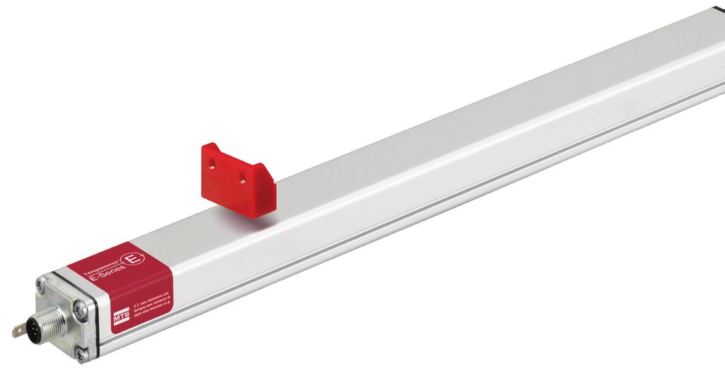
 Sensing element (Waveguide) 1 Sensor model Temposonics EH (rod sensor)")
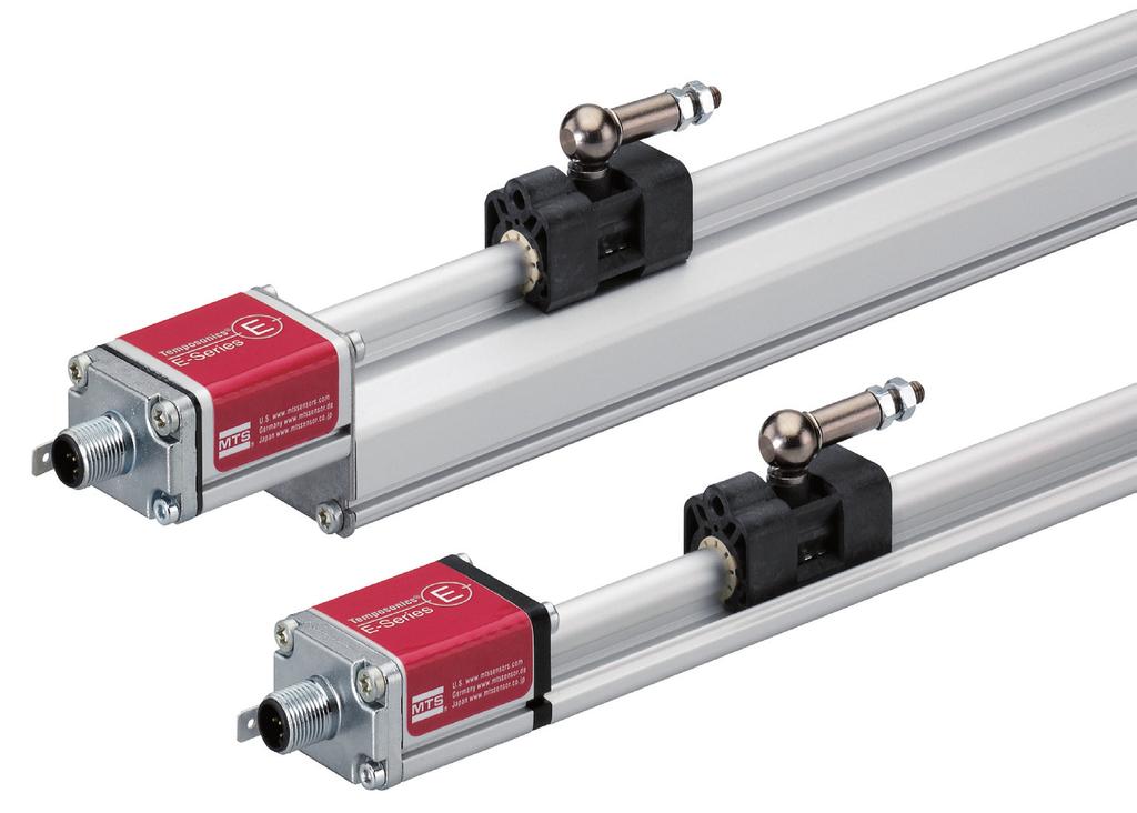
11 4. Product description and commissioning 4.1 Functionality and system design Product designation Position sensor Temposonics E-Series 2 Position magnet (Magnetic fi eld) Sensing element (Waveguide) 1 Sensor model Temposonics EH (rod sensor) Temposonics EP (compact profile sensor) Temposonics EP (ultra low profile sensor) Temposonics EP2 (smooth profile sensor) Temposonics ER (aluminum cylinder with a guided driving rod sensor) Stroke length EH mm (2 100 in.) EP mm (2 100 in.) EL mm (2 100 in.) EP mm (2 100 in.) ER mm (2 60 in.) 4 Torsional strain pulse converter Measurement cycle 1 Current pulse generates magnetic fi eld 2 Interaction with position magnet fi eld generates torsional strain pulse 3 Torsional strain pulse propagates 4 Strain pulse detected by converter 3 5 Output signal IO-Link Application The Temposonics position sensors are used for measurement and conversion of the length (position) variable in the fields of automated systems and mechanical engineering. Principle of operation and system construction The absolute, linear position sensors provided by MTS Sensors rely on the company s proprietary Temposonics magnetostrictive technology, which can determine position with a high level of precision and robustness. Each Temposonics position sensor consists of a ferromagnetic waveguide, a position magnet, a strain pulse converter and supporting electronics. The magnet, connected to the object in motion in the application, generates a magnetic field at its location on the waveguide. A short current pulse is applied to the waveguide. This creates a momentary radial magnetic field and torsional strain on the waveguide. The momentary interaction of the magnetic fields releases a torsional strain pulse that propagates the length of the waveguide. When the ultrasonic wave reaches the end of the waveguide it is converted into an electrical signal. Since the speed of the ultrasonic wave in the waveguide is precisely known, the time required to receive the return signal can be converted into a linear position measurement with both high accuracy and repeatability. 5 Time-of-fl ight converted into position Fig. 2: Time-based magnetostrictive position sensing principle Modular mechanical and electronic construction The sensor rod or profile protects the inner sensor element. The sensor electronics housing, a rugged construction, contains the complete electronic interface with active signal conditioning. The external position magnet is a permanent magnet. Mounted on the mobile machine part, it travels along the sensor rod or profile and triggers the measurement through the sensor rod wall. The sensor can be connected directly to a control system. Its electronics generates a strictly position proportional signal output between start and end position. I 11 I
12 4.2 Styles and installation of Temposonics EH E-Series EH M12 Sensor electronics housing (0.51) (1.89) Null zone 51 (2.01) Stroke length (2 100) Dead zone 63.5 (2.5) 4 pin A/F 34 A/F 34 Ø 34 (Ø 1.34) Magnet 8 (0.31) Controlling design dimensions are in millimeters and measurements in ( ) are in inches Unless otherwise stated, apply to the general tolerances according to DIN ISO 2768-m 14 (0.55) Threaded flange Type»K«,»M«,»W«: M g Type»F«,»L«,»S«: ¾"-16 UNF-3A Sensor rod Type»K«,»L«: Ø 7 ± 0.10 (Ø 0.28 ± 0.01) Type»F«,»M«,»S«,»W«: Ø 10 ± 0.13 (Ø 0.39 ± 0.01) Fig. 3: Temposonics EH sensor Installation of EH with threaded flange Fix the sensor rod via threaded flange M g or ¾"-16 UNF-3A. Fastening torque 50 Nm Hydraulics sealing The flange contact surface is sealed via an O-ring in the undercut (Fig. 4). For threaded flange (¾"-16 UNF-3A)»F«/»L«/»S«: O-ring mm ( in.) (part no ) For threaded flange (M g)»K«/»M«/»W«: O-ring mm ( in.) (part no ) Fig. 4: Mounting example of threaded flange Installation of a rod-style sensor in a fluid cylinder The rod-style version has been developed for direct stroke measurement in a fluid cylinder. Mount the sensor via threaded flange or a hex nut. Mounted on the face of the piston, the position magnet travels over the rod without touching it and indicates the exact position through the rod wall independent of the hydraulic fluid. The pressure resistant sensor rod is installed into a bore in the piston rod. Sensor electronics housing Position magnet Fig. 6: Possibility of sealing Sealing via O-ring in the flange undercut In the case of threaded flange M g, a screw hole based on ISO (Fig. 7) must be provided. See ISO for further information. Note the fastening torque of 50 Nm. Seat the flange contact surface completely on the cylinder mounting surface. The cylinder manufacturer determines the pressure-resistant gasket (copper gasket, O-ring, etc.). The position magnet should not grind on the sensor rod. The piston rod drilling (EH-K / -L: Ø 7 mm rod: Ø 10 mm ( Ø 0.40 in.); EH-M / -S / -F / -W: Ø 10 mm rod: Ø 13 mm ( Ø 0.52 in.)) depends on the pressure and piston speed. Adhere to the information relating to operating pressure. Protect the sensor rod against wear. Fig. 5: Sensor in cylinder I 12 I
13 Notice for metric threaded flanges Thread (d 1 P) d 2 d 3 d 4 d L L 2 L 3 L 4 Z EH-K M g EH-M / -W M g ±1 0.1 A 0.2 A Ød 5 Ød 2 L 3 A R0.4 Ra 3.2 Ra 3.2 A Ød 4 (Gauging) R0.3 R ±5 L 2 L 4 L 1 Z Ød 3 (Reference) Thread (d 1 P) A Pitch diameter Controlling design dimensions are in millimeters This dimension applies when tap drill cannot pass through entire boss. Fig. 7: Notice for metric threaded flange M g based on DIN ISO I 13 I
14 4.3 Styles and installation of Temposonics EP E-Series EP 13 (0.51) Sensor electronics housing 48.8 (1.92) Null zone 35 (1.38) Stroke length (2 100) Dead zone 68 (2.68) 4 pin M12 Magnet 41 (1.61) 31 (1.22) 35.6 (1.40) 50 (1.97) 68 (2.68) 2 (0.08) 14.6 (0.57) Mounting clamps Controlling design dimensions are in millimeters and measurements in ( ) are in inches Unless otherwise stated, apply to the general tolerances according to DIN ISO 2768-m Fig. 8: Temposonics EP sensor Installation of EP The position sensor can be installed in any position. Normally, the sensor is firmly installed and the position magnet is fastened to the mobile machine part. Thus it can travel along the measuring rod without touching it. The sensor is fitted on a flat machine surface using the mounting clamps (Fig. 9). A length-dependent number of these clamps are delivered with the sensor and must be distributed over the profile at regular distances. For fastening use M5 20 screws to DIN 6912 that should be tightened with a fastening torque of 5 Nm. NOTICE Take care to mount the sensor in an axially parallel position to avoid damage of the carriage, magnet and sensor rod. M5 20 max. 5 Nm Adjustable mounting clamps Fig. 9: Mounting clamps with cylinder screw M5 20 (part no ) I 14 I
15 4.4 Styles and installation of Temposonics EL E-Series EL M12 Sensor electronics housing (0.51) (1.77) Null zone 35 (1.38) Stroke length (2 100) Dead zone 68 (2.68) 4 pin 27 (1.06) 14.5 (0.57) Magnet 17 (0.67) 35.6 (1.40) 50 (1.97) 68 (2.68) 2 (0.08) 14.6 (0.57) Mounting clamps Controlling design dimensions are in millimeters and measurements in ( ) are in inches Unless otherwise stated, apply to the general tolerances according to DIN ISO 2768-m Fig. 10: Temposonics EL sensor Installation of EL The position sensor can be installed in any position. Normally, the sensor is firmly installed and the position magnet is fastened to the mobile machine part. Thus it can travel along the measuring rod without touching it. The sensor is fitted on a flat machine surface using the mounting clamps (Fig. 11). A length-dependent number of these clamps are delivered with the sensor and must be distributed over the profile at regular distances. For fastening use M5 20 screws to DIN 6912 that should be tightened with a fastening torque of 5 Nm. NOTICE Take care to mount the sensor in an axially parallel position to avoid damage of the carriage, magnet and sensor rod. M5 20 Fastening torque: 5 Nm Adjustable mounting clamps Fig. 11: Mounting clamps with cylinder screw M5 20 (part no ) I 15 I
16 Magnet Magnet Temposonics E-Series IO-Link 4.5 Styles and installation of Temposonics EP2 E-Series EP2 Null zone 73 (2.87) Mounting support Stroke length (2 100) Dead zone 73 (2.87) 4 pin 13 (0.51) 3 ± 2 (0.12 ± 0.08) 2 (0.08) 27 (1.06) M (1.40) 50 (1.97) 68 (2.68) 14.6 (0.57) Mounting clamps Controlling design dimensions are in millimeters and measurements in ( ) are in inches Unless otherwise stated, apply to the general tolerances according to DIN ISO 2768-m Fig. 12: Temposonics EP2 Installation of EP2 The position sensor can be installed in any position. Normally, the sensor is firmly installed and the position magnet is fastened to the mobile machine part. Thus it can travel along the measuring rod without touching it. The sensor is fitted on a flat machine surface using the mounting clamps (Fig. 13). A length-dependent number of these clamps are delivered with the sensor and must be distributed over the profile at regular distances. For fastening use M5 20 screws to DIN 6912 that should be tightened with a fastening torque of 5 Nm. NOTICE Take care to mount the sensor in an axially parallel position to avoid damage of the carriage, magnet and sensor rod. M5 20 Fastening torque: 5 Nm Adjustable mounting clamps Fig. 13: Mounting clamps with cylinder screw M5 20 (part no ) I 16 I
17 4.6 Styles and installation of Temposonics ER E-Series ER 25 (1) stroke length ( stroke length) 3 25 (0.12)(1) Stroke length (2 60) 17.8 (0.7) 35.5 (1.40) M pin 20 (0.79) 37.8 (1.49) 51 (2.01) Optional: Adjustable rod end M6 / ¼"-28 UNF Optional: Mounting clamps Optional: Adjustable rod end M6 / ¼"-28 UNF 50 (1.97) 68 (2.68) Controlling design dimensions are in millimeters and measurements in ( ) are in inches Unless otherwise stated, apply to the general tolerances according to DIN ISO 2768-m Fig. 14: Temposonics ER There are two ways to install the sensor ER: 1. Via the mounting clamps The position sensor can be installed in any position. The sensor is fitted on a flat machine surface using the mounting clamps (Fig. 15). A length-dependent number of must be distributed over the profile at regular distances. For fastening use M5 20 screws to DIN 6912 that should be tightened with a fastening torque of 5 Nm. NOTICE Take care to mount the sensor in an axially parallel position to avoid damage of the carriage and sensor rod. NOTICE Do not raise up the ER sensor, if the lifting rod is extended. It causes serious damage M5 20 Fastening torque: 5 Nm Adjustable mounting clamps Fig. 15: Mounting clamps with cylinder screw M5 20 (part no ) 2. Via the adjustable rod end The position sensor can be installed in any position. The sensor is mechanically connected via adjustable rod ends (part no / part no ) I 17 I
18 4.7 Magnet installation 2 Magnet Typical Sensors Benefits M4 1 Ring magnets Rod model (EH) Rotationally symmetrical magnetic field 8 ±2 (0.31 ±0.08) Air gap: 3 ±2 (0.12 ±0.08) Sensor element U-magnets Profile & rod models (EH, EP) Height tolerances can be compensated 1 Block magnet 2 Non-magnetic mounting plate Fig. 18: Mounting of block magnet (part no ), example of EL sensor Block magnets Profile & rod models (EH, EP, EL & EP2) Magnet sliders Profile models (EP & EL) The magnet can be lifted off Height tolerances can be compensated The magnet is guided through the profile The distance between the magnet and the waveguide is strictly defined Easy coupling via the ball joint Magnet mounting with magnetic material When using magnetic material the dimensions of Fig. 19 must be observed. A. If the position magnet aligns with the drilled piston rod B. If the position magnet is set further into the drilled piston rod, install another non-magnetic spacer above the magnet. A B Fig. 16: Typical use of magnets 1 Magnetic material Mounting the ring magnets, U-magnets & block magnets Install the magnet using non-magnetic material for mounting device, screws, spacers etc.. The magnet must not grind on the sensor rod. Alignment errors are compensated via the air gap. Permissible surface pressure: Max. 40 N/mm 2 (only for ring magnets and U-magnets) Fastening torque for M4 screws: 1 Nm; use washers, if necessary Minimum distance between position magnet and any magnetic material has to be 15 mm (0.6 in.) (Fig. 19). If no other option exists and magnetic material is used, observe the specified dimensions (Fig. 19). NOTICE Mount ring magnets and U-magnets concentrically. Mount block magnets centrically over the sensor rod or the sensor profile. Do not exceed the maximum acceptable gap (Fig. 17, Fig. 18). Air gap: 1.75 ±1 (0.07 ±0.04) 2 M4 1 Magnet Fig. 19: Installation with magnetic material 2 3 Sensors with stroke lengths 1 meter (3.3 ft.) Support horizontally installed sensors with a stroke length from 1 meter (3.3 ft.) mechanically at the rod end. Without the use of a support, rod and position magnet may be damaged. A false measurement result is also possible. Longer rods require evenly distributed mechanical support over the entire length (e.g. part no ). Use an U-magnet (Fig. 20) for measurement. U-magnet 3 Magnet 1 Null zone, depends on sensor model (see Fig. 21/22) 2 Distance between position magnet and any magnetic material ( 15 mm ( 0.6 in.)) 3 Non-magnetic spacer ( 5 mm ( 0.2 in.)) Recommendation: 8 mm (0.31 in.) Sensor rod Non-magnetic fixing clip 1 U-magnet 2 Non-magnetic mounting plate Fig. 20: Example of sensor support (part no ) Fig. 17: Mounting of U-magnet (part no ), example of EP sensor Controlling design dimensions are in millimeters and measurements in ( ) are in inches I 18 I
19 Start and end positions of the position magnets Consider the start and end positions of the position magnets during the installation. To ensure that the entire stroke length is electrically usable, the position magnet must be mechanically mounted as follows. E-Series EL with magnet slider S, N, V, G Start position 19 (0.75) End position 84 (3.3) E-Series EH with ring- / U-magnet Start position 51 (2.01) End position 63.5 (2.5) E-Series EL with block magnet Start position 32.5 (1.29) End position 70.5 (2.78) E-Series EH with block magnet Start position 48.5 (1.91) End position 66 (2.6) E-Series EP2 with block magnet Start position 73 (2.87) End position 73 (2.87) E-Series EP with magnet slider S, N, V, G Start position 19 (0.75) End position 84 (3.3) Fig. 22: Start- and end positions of magnets, part 2 E-Series EP with U-magnet Start position 35 (1.38) End position 68 (2.68) E-Series EP with block magnet Start position 32.5 (1.29) End position 70.5 (2.78) Fig. 21: Start- and end positions of magnets, part 1 Controlling design dimensions are in millimeters and measurements in ( ) are in inches I 19 I
20 4.8 Electrical connections Placement of installation and cabling have decisive influence on the sensor s electromagnetic compatibility (EMC). Hence correct installation of this active electronic system and the EMC of the entire system must be ensured by using suitable metal connectors, shielded* cables and grounding. Overvoltages or faulty connections can damage its electronics despite protection against wrong polarity. NOTICE 1. Do not mount the sensors in the area of strong magnetic or electric noise fields. 2. Never connect / disconnect the sensor when voltage is applied. Instructions for connection Use low-resistant twisted pair and shielded cables. Connect the shield to ground externally via the controller equipment. Keep control and sign leads separate from power cables and sufficiently far away from motor cables, frequency inverters, valve lines, relays, etc.. Use only connectors with metal housing and connect the shielding to the connector housing. Keep the connection surface at both shielding ends as large as possible. Connect the cable clamps to function as a ground. Keep all non-shielded leads as short as possible. Keep the earth connection as short as possible with a large cross section. Avoid ground loops. With potential differences between machine and electronics earth connections, no compensating currents are allowed to flow across the cable shielding. Recommendation: Install potential compensating leads with large cross section or use cables with separate double shielding, and connect only one end of the shield. Use only stabilized power supplies in compliance with the specified connecting values. D44 Signal + power supply M12 male connector (A-coded) View on sensor Fig. 24: Connector wiring D44 Pin Function VDC ( 15 / +20 %) 2 DI / DQ 3 DC Ground (0 V) 4 C / Q Grounding of profile and rod sensors Connect the sensor electronics housing to machine ground. Ground sensor types EP, EL, EP2 and ER via ground lug as shown in Fig. 23. The sensor type EH is grounded via thread. Fig. 23: Grounding via ground lug e.g. profile sensor */ The use of shielded cables is a recommendation of MTS Sensors to afford a better protection against signal disturbances I 20 I
21 Temposonics E-Series IO-Link 4.9 Frequently ordered accessories Additional options available in our Accessories Guide Ø 32.8 (Ø 1.29) Ø 23.8 (Ø 0.94) Ø 13.5 (Ø 0.53) Ø 4.3 (Ø 0.17) 7.9 (0.31) Ø 25.4 (Ø 1) Ø 4.3 (Ø 0.17) Ø 17.4 (Ø 0.69) Ø 13.5 (Ø 0.53) Ø 13.5 (Ø 0.53) 7.9 (0.31) 7.9 (0.31) Ring magnet OD17.4 Part no Ø 32.8 (Ø 1.29) 60 Ø 23.8 (Ø 0.94) Ø 13.5 (Ø 0.53) 3 (0.12) Position magnets (0.31) Ring magnet OD33 Part no Ring magnet OD25.4 Part no For: EH For: EH For: EH For: EH, EP Material: PA ferrite GF20 Weight: Ca. 14 g Surface pressure: Max. 40 N/mm2 Fastening torque for M4 screws: 1 Nm Operating temperature: C ( F) Material: PA ferrite Weight: Ca. 10 g Surface pressure: Max. 40 N/mm2 Operating temperature: C ( F) Material: PA neobind Weight: Ca. 5 g Surface pressure: Max. 20 N/mm2 Operating temperature: C ( F) Material: PA ferrite GF20 Weight: Ca. 11 g Surface pressure: Max. 40 N/mm2 Fastening torque for M4 screws: 1 Nm Operating temperature: C ( F) U-magnet OD33 Part no Position magnets M5 33 (1.3) 19.5 (0.77) M5 40 (1.58) 40 (1.58) Ø 4.3 (Ø 0.17) 20.5 (0.81) 1.5 (0.06) (1.93) 14 (0.55) 14.9 (0.59) 7.6 (0.3) 57 (2.24) 25.3 (1) Ø 19.8 (Ø 0.78) 25.3 (1) 20 (0.79) 14 (0.55) 43 (1.69) 18 Ø 30.5 (Ø 1.2) 14 (0.55) 8 ± 2 (0.31 ± 0.08) Distance to sensor element Ring magnet Part no Magnet slider S Part no Magnet slider V Part no Block magnet Part no For: EH For: EP, EL For: EP, EL For: EH, EP, EL, EP2 Material: PA ferrite coated Weight: Ca. 13 g Surface pressure: 20 N/mm2 Operating temperature: C ( F) Material: GFK, magnet hard ferrite Weight: Ca. 35 g Operating temperature: C ( F) Material: GFK, magnet hard ferrite Weight: Ca. 35 g Operating temperature: C ( F) Material: Hard ferrite Weight: Ca. 20 g Fastening torque for M4 screws: 1 Nm Operating temperature: C ( F) Magnet spacer Sealing Ø 31.8 (Ø 1.25) Ø 23.8 (Ø 0.94) Ø 14.3 (Ø 0.56) Ø 15.3 (Ø 0.6) Ø 4.3 (Ø 0.17) Ø 16.4 (Ø 0.65) Ø 2.2 (Ø 0.09) 3.2 (0.13) Ø 2.2 (Ø 0.09) Magnet spacer Part no O-ring for flange M g Part no O-ring for flange ¾"-16 UNF-3A Part no For: EH For: EH For: EH Material: Aluminum Weight: Ca. 5 g Surface pressure: 20 N/mm2 Fastening torque for M4 screws: 1 Nm Application: Flange M Material: Fluoroelastomer 75 ± 5 durometer Application: Flange ¾"-16 UNF Material: Fluoroelastomer 75 ± 5 durometer Controlling design dimensions are in millimeters and measurements in ( ) are in inches I 21 I
22 Cable connectors 7 Cable ~ 57 (~2.25) Ø 15 (Ø 0.6) M12 Ø 15 (Ø 0.6) 26.5 (1.04) Ø 20 (Ø 0.79) ~53 (~ 2.09) 38 (1.5) Ø 20 (Ø 0.79) Ø 12.2 (Ø 0.48) Ø 11.6 (Ø 0.46) 4 (0.16) 45.5 (1.8) M12 Ø 8.8 (Ø 0.35) Ø 11.6 (Ø 0.45) 12 (0.5) 31.5 (1.24) M12 female connector (5 pin), straight Part no Material: GD-Zn, Ni Termination: Screw; max. 1.5 mm² Contact insert: CuZn Cable Ø: 4 8 mm ( in.) Operating temperature: C ( F) Ingress protection: IP67 Fastening torque: 0.6 Nm M12 female connector (5 pin), angled Part no Material: GD-Zn, Ni Termination: Screw; max mm² Contact insert: CuZn Cable Ø: 5 8 mm ( in.) Operating temperature: C ( F) Ingress protection: IP67 Fastening torque: 1 Nm Cable with M12 female connector (5 pin), straight pigtail Part no Features: Shielded Cable length: 5 m (16.4 ft.) Ingress protection: IP67 Cable with M12 female connector (5 pin), angled pigtail Part no Features: Shielded Cable length: 5 m (16.4 ft.) Ingress protection: IP67 Hex nut Mounting hardware Mounting clamp A/F 27 M g 8.7 (0.34) A/F 28 ¾"-16 UNF-3A 11 (0.43) 60 (2.36) 16 (0.63) 12 (0.47) 20 (0.79) Ø 3.2 (Ø 0.13) M3 fastening screws (6 ) 3.2 (0.13) 4 Holes Ø 5.4 (Ø 0.21) 31 (1.22) 9 (0.35) 2 (0.08) 50 (1.97) 68 (2.68) Mounting clamp width: 14.6 (0.57) 10 (0.39) Hex-jam nut M18 Part no Hex-jam nut ¾" Part no Fixing clip Part no Fixing clip Mounting clamp Part no For: EH For: EH For: EH For: EP, EL, EP2, ER Application: M thread Material: Steel, 2 zinc, plated Rod ends Application: ¾"-16 UNF thread Material: Zinc plated with nylon insert Application: Used to secure sensor rods (Ø 10 mm (Ø 0.39 in.)) when using an U-magnet Material: Brass, non-magnetic Material: Stainless steel / (AISI 304 / 303) Ø 6 (Ø 0.24) Ø 6.35 (Ø 0.25) 26.5 (1.04) 36.5 (1.44) M6 9 (0.35) Tilt angle 14 (0.55) 26.5 (1.04) 36.5 (1.44) ¼"-28 UNF 9 (0.35) Tilt angle 14 (0.55) Rod end with M6 thread (for metric stroke length measurement) Part no For: ER-M Rod end with ¼"-28 thread (for US customary stroke length measurement) Part no For: ER-S 3/ Follow the manufacturer s mounting instructions Controlling design dimensions are in millimeters and measurements in ( ) are in inches Manuals & Software available at: I 22 I
23 5. Operation IO-Link IO-Link is an open standard according to IEC It is a serial, bi-directional point-to-point connection for signal transmission and energy supply. The bi-directional communication enables consistent communication between sensors and the controller as well as consistent diagnostic information down to the sensor level. The E-Series IO-Link sensor is an IO-Link device which is connected to an IO-Link master. Read the operation manual for the IO-Link master to which the IO-Link device is connected. The E-Series IO-Link parameters in the IO Device Description (IODD) file allow the identification of the sensor on the IO-Link master, adjustment of certain sensor parameters for the applicaiton and the output of warnings and errors. IO Device Description (IODD) file The IODD file stores a variety of information about the device for system integration. The IODD file for E-Series IO-Link is available at NOTICE There are two IODD files available for the E-Series IO-Link sensors. Please choose the appropiate IODD file for your E-Series IO-Link: 1. IODD short (MTS-E-Series_IOLink-xxxxxxx-IODD1.1.xml)* for sensors with stroke length 1000 mm ( 39 in.) 2. IODD long (MTS-E-Series_IOLink2ms-xxxxxxx-IODD1.1.xml)* for sensors with stroke length > 1000 mm (> 39 in.) The difference between both files is the cycle time. The E-Series IO-Link can be connected to IO-Link masters with a maximum master cycle time of 20 ms. Contact MTS Sensors if you use the sensor E-Series IO-Link in an application with a master cycle time > 20 ms. 5.1 Identification parameter These parameters are used to identify the sensor when connected to an IO-Link master. Index Subindex Parameter Data type Access Value 0x10 0x00 Vendor name string ro MTS Sensor Technologie GmbH and Co. KG 0x11 0x00 Vendor text string ro 0x12 0x00 Product name string ro E-Series IO-Link (short) / E-Series IO-Link (long) 0x13 0x00 Product ID string ro E-Series IO-Link (short) / E-Series IO-Link (long) 0x14 0x00 Product text string ro MTS Sensors E-Series 0x15 0x00 Serial number string ro e.g x16 0x00 Hardware revision string ro 1.0 0x17 0x00 Firmware revision string ro 1.16 Table 1: Identification parameters The "Application specific tag" allows the user to assign the IO-Link device a random, 32-byte string. This can only be used for application-specific identification. Index Subindex Parameter Data type Access Length Description 0x18 0x00 Application specific tag string rw 32 bytes The user can assign the sensor with a random name Table 2: Application specific tag */ xxxxxxx = date (e.g ) I 23 I
24 5.2 Standard commands The following commands can be used to reset the device, or reset all parameters to default settings. Index Subindex Parameter Access Command Description 0x02 0x00 Reset device wo 0xA0 Reset the device 0x02 0x00 Reset factory settings wo 0x82 Reset all parameters to default settings Table 3: Standard commands 5.3 Measuring parameter These parameters allow the sensor to be adapted to the application. The resolution, a filter of the measured value and the measuring direction can all be configured. Index Subindex Parameter Data type Access Length Default Value Commands Description 0x71 0x00 Resolution unsigned integer rw 4 bytes 5 5 = 5 µm 10 = 10 µm 20 = 20 µm 50 = 50 µm 100 = 100 µm The resolution of measurement is the smallest difference between two position values. It has no relation to the accuracy of the measurement. The output is in µm steps. 0x72 0x00 Filter unsigned integer rw 4 bytes 0 0 = Filter off 2 = Filter grade 2 4 = Filter grade 4 8 = Filter grade 8 The filter of the current application is based on the principle of moving average filter. The current position value is given out of the average of a previous amount of positions and the current measured position. 0x73 0x00 Measuring direction bool rw 1 byte False Table 4: Measuring parameters False = Forward True = Backwards Forward: From sensor electronics housing to rod end Backwards: From rod end to sensor electronics housing 5.4 Offset The offset is added to the current position value. Index Subindex Parameter Data type Access Length Value Description 0x70 0x00 Offset integer rw 4 bytes Value in µm Write and read the offset position Index Subindex Function Data type Access Length Command Description 0x78 0x00 Teach offset bool wo 1 byte True Read the current position and set it as the offset Table 5: Offset parameters For the teach procedure the user moves the position magnet to the required position. Click the appropriate button in the graphical user interface (GUI) of the IO-Link master in order to define the start or end position. The new position is stored in the sensor. How the offset works Example 1: 1. Offset: 0 2. Current position value: µm (80 mm) 3. New offset is set: µm (120 mm) 4. New position value: 80 mm mm = µm (200 mm) Example 2: 1. Offset: 0 2. Current position value: µm (80 mm) 3. New offset is set: µm ( 120 mm) 4. New position value: 80 mm 120 mm = µm ( 40 mm) 1 Offset: 0 µm 2 Ex-position: µm 3 Set offset: µm 4 New read position: µm 1 Offset: 0 µm 2 Ex-position: µm 3 Set offset: µm 4 New read position: µm Fig. 25: How the offset works I 24 I
25 5.5 Switch points The digital output of the sensor on pin 2 (DI / DQ) can be configured as a switch point (see "4.8 Electrical connections" on page 20). This switch point is output in parallel to the position value. The switch point respectively the switch points and the switch logic can be adjusted. Two switch modes are possible: 1. One switch point (single point mode) 2. Two switch points (window mode) The logic can also be changed between inverted and non-inverted. Teach Switch Points For the teach procedure the user moves the position magnet to the required position. Click the appropriate button in the graphical user interface (GUI) of the IO-Link master in order to define switch point 1 or switch point 2. The new position is stored in the sensor. Index Subindex Parameter Data type Access Length Value Description 0x7B 0x01 Switch point 1 integer rw 4 bytes Value in µm Write and read switch position 1 0x02 Switch point 2 integer rw 4 bytes Value in µm Write and read switch position 2 Index Subindex Function Data type Access Length Command Description 0x79 0x00 Teach switch point 1 bool wo 1 byte True Read the current position and set it as switch point 1. 0x7A 0x00 Teach switch point 2 bool wo 1 byte True Read the current position and set it as switch point 2. 0x7C 0x00 Switch logic bool rw 4 bytes 0x7D 0x00 Switch mode unsigned integer rw 4 bytes Table 6: Switch point parameters False = Non-inverted True = Inverted 0 = Deactivate (default) 1 = Single point mode 2 = Window mode Defines whether the switching information is inverted or non-inverted. Deactivate: The switch function is out of function Single point mode: Only switch point 1 will be considered by the switch function. Window mode: Switch point 1 and switch point 2 will be considered by the switch function. Switch point Deactivate (default) Single point mode Switch logic: Non-inverted Switch logic: Inverted 24 VDC VDC 24 VDC 0 VDC Switch point 1 0 VDC 24 VDC Switch point 1 Window mode Switch logic: Non-inverted Switch logic: Inverted 24 VDC 0 VDC 24 VDC Switch point 1 Switch point 2 0 VDC Switch point 1 Switch point 2 Fig. 26: Functionality of switch point parameters NOTICE The DI / DQ output must be limited to a current consumption of 100 ma. I 25 I
26 5.6 Set measurement range The start and end point of the measurement can be set by the user in order to customize the measuring range. Teach measurement points For the teach-in procedure the user moves the position magnet to the required position. Click the appropriate button in the graphical user interface (GUI) of the IO-Link master in order to define set point 1 or set point 2. The new position is stored in the sensor. Index Subindex Parameter Data type Access Length Value Description 0x74 0x75 0x00 0x00 Set start position Set end position integer integer rw rw 4 bytes 4 bytes Value in µm Value in µm The start and end point of the measurement range can be set by the user in order to customize the measurement range. If those points are set, the sensor will give a warning whenever the position magnet is above (Error code: 0x8CA3) or under (Error code: 0x8CA4) the measurement range. Index Subindex Function Data type Access Length Command Description 0x76 0x00 Teach start position bool wo 1 byte True Read the current position and set it as the start measurement point 0x77 0x00 Teach end position bool wo 1 byte True Read the current position and set it as the end measurement point Table 7: Setpoint parameters Factory setting Warning Start position Stroke length End position Warning NOTICE The default value of start position and end position are the factory default values of the start and end of the stroke length defined by the sensor model. Customer setting Use only the active stroke length for the definition of the start and end point (see chapter "4.7 Magnet installation" on page 18). Do not set the start or end position to in the null or dead zones. Warning Warning Start position End position Fig. 27: How to set the measurement range I 26 I
27 5.7 Error / warning messages If any issues happen, the following warnings and error messages will be issued. Code Mode Type Message 0x8CA1 (Dis)appear Error More than one magnet 0x8CA2 (Dis)appear Error No magnet 0x8CA3 (Dis)appear Warning Over range of measurement 0x8CA4 (Dis)appear Warning Under range of measurement Table 8: Error codes specified by MTS Sensors Code 0x8011 0x8012 0x8022 0x8023 0x8030 0x8031 0x8032 0x8033 0x8034 0x8035 Message Index not available Sub-index not available Service temporarily not available local control Access denied Parameter value out of range Parameter value above the limit Parameter value below the limit Parameter length overrun Parameter length underrun Function not available Table 9: Error codes defined by the IO-Link specification 5.8 Device Access Lock The parameter "Device Access Lock" allows the user to activate or deactivate parameter management. Set bit 1 to "0" to unlock the parameter management of the IO-Link device; so the IO-Link master can read the data storage of the IO-Link device and write to the data storage of the IO-Link device. Index Subindex Parameter Data type Access Length Default value Description 0x000C 0x00 Device access lock Table 10: Device access lock parameter Bits RecordT of BooleanT rw 2 bytes false Standardized device locking functions Hex Description x00 Data storage access unlocked (default value) x02 Data storage access locked I 27 I

. 6.2 Import IODD files Visit www.mtssensors.")
 2. IODD long (MTS-E-Series_IOLink2ms-xxxxxxxx-IODD1.1.xml)* for sensors with stroke length > 1000 mm (> 39 in.) The difference between both files is the cycle time.")
28 6. Integration into Automation Studio 6.1 Introduction of "Automation Studio" The following is a description how to integrate a Temposonic E-Series sensor with IO-Link output using Automation Studio by B&R (Bernecker + Rainer Industrie-Elektronik Ges.m.b.H.). The PLC is a X20CP1584 with connected interface card X20DS438A. After successfull file import the IODD file will be shown in the column "Toolbox - Hardware Catalog" (Fig. 29). 6.2 Import IODD files Visit and download the IO Device Description (IODD) file. NOTICE There are two IODD files for E-Series IO-Link sensors available: 1. IODD short (MTS-E-Series_IOLink-xxxxxxxx-IODD1.1.xml)* for sensors with stroke length 1000 mm ( 39 in.) 2. IODD long (MTS-E-Series_IOLink2ms-xxxxxxxx-IODD1.1.xml)* for sensors with stroke length > 1000 mm (> 39 in.) The difference between both files is the cycle time. Select the appropriate file for your sensor. You can check loaded IODD files at sensor identification (Fig. 38). When the download is finished, open Automation Studio and import the downloaded IODD file (Fig. 28). The DTM catalog will update automatically. Fig. 29: Import DTM Device Choose the correct IODD file ("short" for stroke lengths 1000 mm ( 39 in.) or "long" for stroke lengths > 1000 mm (> 39 in.). Link the E-Series IO-Link sensor with the IO-Link master card (X20DS438A) (Fig. 30) and activate the DTM server in the settings of the PLC (X20CP1584) (Fig. 31). Fig. 30: Link sensor to PLC Fig. 28: Import DTM Device */ xxxxxxxx = date (e.g ) Fig. 31: Activate DTM server I 28 I
 (\"USINT\" unsigned shot integer) which linked to the data of the sensor process data in the logical view of \"Global.var\". Fig.")
. The process data of the sensor consists of 4 bytes and contains the measurement.")
29 Configure the settings of the IO-Link master (X20DS438A) and set the operating mode of the IO-Link interface to "Operate" (Fig. 32). Create 4 single byte variables (PositionByte0 PositionByte3) ("USINT" unsigned shot integer) which linked to the data of the sensor process data in the logical view of "Global.var". Fig. 34: Configuration of "Global.var" Fig. 32: Operating mode: Operate In addition create a variable ("DINT" double integer) to store the composed position (ComposedPosition). 6.3 Configure process data Configure the input process data of the sensor (Fig. 33). The process data of the sensor consists of 4 bytes and contains the measurement. Open the I/O Mapping of the IO-Link master card (X20DS438A) and link the Input Data01_1 Input Data01_4 with the single byte variables (PositionByte3 PositionByte0). Fig. 35: Link the input data with single byte variables Fig. 33: Process data I 29 I
30 To compose the position from the position bytes create a program (in this example it is called "ComposePosition") with following code: Initialization method Initialization of variables PositionByte0...PositionByte3 and ComposedPosition.The variable ComposedPosition stores the measured position value. #include <bur/plctypes.h> #ifdef _DEFAULT_INCLUDES #include <AsDefault.h> #endif void _INIT ComposePositionInit(void) { /* initialize variables */ PositionByte0 = 0; PositionByte1 = 0; PositionByte2 = 0; PositionByte3 = 0; ComposedPosition = 0; } Cyclic Method Cyclical program call to shift the variables (PositionByte0 PositionByte3) into the variable ComposedPosition in the correct position. The ComposedPosition contains the measured value. #include <bur/plctypes.h> #ifdef _DEFAULT_INCLUDES #include <AsDefault.h> #endif void _CYCLIC ComposePositionCyclic(void) { /* compose position out of input bytes */ ComposedPosition = (PositionByte3 << 24) (PositionByte2 << 16) (PositionByte1 << 8) PositionByte0; } I 30 I


31 With that code running, you can observe how the position is composed out of the input bytes using the variable watch window. Fig. 39: Sensor parameter Fig. 36: Variable watch window With the device configuration UI the sensor configuration can be done in a convenient way. For detailed descriptions about the parameters see chapter "5. Operation" on page 23. Fig. 37: Device configuration Fig. 38: Sensor identification I 31 I
32 7. Maintenance and troubleshooting 7.1 Error conditions, troubleshooting See chapter "5. Operation" on page Maintenance The sensor is maintenance-free. 7.3 Repair Repairs of the sensor may be performed only by MTS Sensors or a repair facility explicitly authorized by MTS Sensors. 7.4 List of spare parts No spare parts are available for this sensor. 7.5 Transport and storage The conditions of transport and storage of the sensor match the operating conditions mentioned in this document. 8. Removal from service / dismantling The product contains electronic components and must be disposed of in accordance with the local regulations. I 32 I
Temposonics Magnetostrictive Linear Position Sensors. Temposonics GB-Series Brief Instructions
 Temposonics Magnetostrictive Linear Position Sensors Table of contents. Introduction...3 2. Safety instructions...4 2. Intended use...4 2.2 Forseeable misuse...4 2.3 Installation, commissioning and operation...5
Temposonics. Magnetostrictive Linear Position Sensors. R-Series Profinet IO RT Operation Manual
 Temposonics Magnetostrictive Linear Position Sensors R-Series Profinet IO RT Table of contents 1. Introduction... 3 1.1 Purpose and use of this manual... 3 1.2 Used symbols and warnings... 3 2. Safety
Temposonics Magnetostrictive Linear Position Sensors. Temposonics E-Series Brief Instructions
 Temposonics Magnetostrictive Linear Position Sensors Temposonics E-Series Table of contents 1. Introduction...3 2. Safety instructions...4 2.1 Intended use...4 2.2 Forseeable misuse...4 2.3 Installation,
Temposonics. Magnetostrictive Linear Position Sensors. GB-Series Analog Operation Manual
 Temposonics Magnetostrictive Linear Position Sensors GB-Series Analog Table of contents 1. Introduction...3 1.1 Purpose and use of this manual...3 1.2 Used symbols and warnings...3 2. Safety instructions...3
Temposonics. Magnetostrictive Linear Position Sensors. R-Series Ethernet/IP TM Operation Manual
 Temposonics ostrictive Linear Position Sensors R-Series Ethernet/IP TM Table of contents 1. Introduction... 2 1.1 Purpose and use of this manual... 2 1.2 Used symbols and warnings... 2 2. Safety instructions...
Temposonics GENERATION THE NEW I AM. Magnetostrictive Linear Position Sensors. Temposonics R-Series V Profinet RT & IRT Operation Manual
 Temposonics Magnetostrictive Linear Position Sensors Temposonics R-Series V Profinet RT & IRT I AM V THE NEW GENERATION Table of contents 1. Introduction... 3 1.1 Purpose and use of this manual... 3 1.2
Temposonics. Magnetostrictive Linear Position Sensors. MH-Series Flexible MH Installation Manual
 Temposonics Magnetostrictive Linear Position Sensors MH-Series Flexible MH Operation Manual Table of contents 1. Introduction... 3 1.1 Purpose and use of this manual... 3 1.2 Used symbols and warnings...
Temposonics. Magnetostrictive Linear Position Sensors. MHRM Analog Data Sheet. For embedded or externally threaded installation
 Temposonics ostrictive Linear Position Sensors MHRM Analog For embedded or externally threaded installation Sensor rod with Ø 7 mm or Ø 0 mm Resolution: ±0. mm typ. Compliant with EN 50-3- MEASURING TECHNOLOGY
Temposonics. Magnetostrictive, Absolute, Non-contact Linear-Position Sensors. R-Series Models RP and RH DeviceNet Output.
 Temposonics Magnetostrictive, Absolute, Non-contact Linear-Position Sensors R-Series Models RP and RH DeviceNet Output SENSORS Document Part Number 550651 Revision F Data Sheet Model RP Profile-style position
Temposonics. E-Series Analog + Start / Stop. Magnetostrictive Position Sensors. Temposonics EP Measuring range mm / mm SENSORS
 Temposonics Magnetostrictive Position Sensors m SENSORS E-Series Temposonics EP Measuring range 50-1500 mm / 50-3250 mm... innovative Sensor-Parameter Handling Linear, Absolute Measurment Contactless Sensing
Temposonics. Magnetostrictive Linear Position Sensors
 Temposonics Magnetostrictive Linear Position Sensors TH Analog ATEX / IECEx / CEC / NEC / EAC Ex certified / Japanese approval / Safety SIL 2 capable Table of contents 1. Introduction...3 1.1 Purpose and
Temposonics. G-Series Analog Redundant. Magnetostrictive Position Sensors. Redundancy for enhanced safety
 Temposonics Magnetostrictive Position Sensors m SENSORS G-Series Redundant Temposonics GT2 and GT3 Measuring length 25-1500 mm Redundancy for enhanced safety Up to 3 totally separated, independent measuring
Temposonics. Magnetostrictive Linear Position Sensors. TH Analog Data Sheet
 Temposonics ostrictive Linear Position Sensors TH Analog ATEX / IECEx / CEC / NEC / EAC Ex certified / Japanese approval Continuous operation under harsh industrial conditions Flameproof / Explosionproof
Temposonics. Magnetostrictive Linear Position Sensors
 Temposonics Magnetostrictive Linear Position Sensors TH Analog ATEX / IECEx / CEC / NEC / KCs / EAC Ex certified / Japanese approval / Safety SIL 2 capable Table of contents 1. Introduction...3 1.1 Purpose
Temposonics. Magnetostrictive, Absolute, Non-contact Linear-Position Sensors. R-Series Models RP and RH Ethernet POWERLINK.
 Temposonics Magnetostrictive, Absolute, Non-contact Linear-Position Sensors R-Series Models RP and RH Ethernet POWERLINK SENSORS Document Part Number 551191 Revision A Data Sheet Model RP Profile-style
Temposonics Magnetostrictive, Absolute, Non-contact Linear-Position Sensors
 Temposonics Magnetostrictive, Absolute, Non-contact Linear-Position Sensors E-Series Model EH Synchronous Serial Interface (SSI) Output Data Sheet SENSORS Document Part Number: 551314 Revision B Model
Temposonics. Magnetostrictive Linear Position Sensors. MH-Series MH5 Analog Data Sheet
 Temposonics Magnetostrictive Linear Position Sensors MH-Series MH5 Analog Linearity < 0.04 % F.S. Resolution typ. ±0.1 mm Stainless steel housing 1. Product description and technology Temposonics sensors
Temposonics. R-Series DeviceNet. Magnetostrictive Position Sensors. Intelligent Design. Temposonics RP and RH Measuring length mm SENSORS
 Temposonics Magnetostrictive Position Sensors m SENSORS R-Series Temposonics RP and RH Measuring length 25-7600 mm Rugged Industrial Sensor Linear and Absolute Measurement LEDs for Sensor Diagnostic Contactless
Temposonics. Magnetostrictive Linear Position Sensors. TH CANbus Data Sheet
 Temposonics ostrictive Linear Position Sensors TH CANbus ATEX / IECEx / CEC / NEC / EAC Ex certified / Japanese approval Continuous operation under harsh industrial conditions Flameproof / Explosionproof
CANBUS G. Up to mm ( in.) < ± 0.01% of full stroke or ± 0.04 mm ( in.), whichever is greater*
 < ± 0.01% of full stroke or ± 0.04 mm ( in.), whichever is greater*") 27295 8/11/03 T 7:42 AM Page 1 E M P O S O N I C S R S E R I E S CANBUS 550541 G P r o d u c t S p e c i f i c a t i o n s PARAMETER S P E C I F I C AT I O N Measured Variable: Resolution: Non-Linearity:
27295 8/11/03 T 7:42 AM Page 1 E M P O S O N I C S R S E R I E S CANBUS 550541 G P r o d u c t S p e c i f i c a t i o n s PARAMETER S P E C I F I C AT I O N Measured Variable: Resolution: Non-Linearity:
Temposonics. M-Series Analog. Magnetostrictive Position Sensors. Temposonics MH Measuring length mm SENSORS
 Temposonics Magnetostrictive Position Sensors m SENSORS M-Series Temposonics MH Measuring length 50-2500 mm Compact Sensor for Mobile Hydraulics Linear, Absolute Measurement in Hydraulic Cylinders Contactless
Temposonics. Magnetostrictive Linear Position Sensors. TH Analog SIL 2 capable Data Sheet
 Temposonics ostrictive Linear Position Sensors TH Analog SIL 2 capable ATEX / IECEx / CEC / NEC / EAC Ex certified / Japanese approval Continuous operation under harsh industrial conditions Flameproof
Temposonics. M-Series Analog. Absolute, Non-Contact Position Sensors. Temposonics MH Measuring length mm. Compact Sensor for Mobile Hydraulics
 Temposonics Absolute, Non-Contact Position Sensors M-Series Temposonics MH Measuring length 50-2500 mm Compact Sensor for Mobile Hydraulics Linear, Absolute Measurement in Hydraulic Cylinders Contactless
Temposonics. Absolute, Non-Contact Position Sensors. MH Series. Temposonics MB Analog. Technical Data / Description
 Temposonics Absolute, Non-Contact Position Sensors MH Series Technical Data / Description Document No. 551220 Revision E Compact Sensor for Mobile Hydraulics Linear, absolute Measurement in Hydraulic Cylinders
Temposonics. G-Series Analog or Start/Stop. Absolute, Non-Contact Position Sensors. Temposonics GP and GH Stroke length mm depends on output
 Temposonics Absolute, Non-Contact Position Sensors G-Series Temposonics GP and GH Stroke length 50...7600 mm depends on output C GP GH Position ~ Time Output signal indicating to magnet's position Sensor
Temposonics. Magnetostrictive Linear-Position Sensors. R-Series Model RP and RH Sensors Synchronous Serial Interface (SSI) Output D
 Output D") Temposonics Magnetostrictive Linear-Position Sensors R-Series Model RP and RH Sensors Synchronous Serial Interface (SSI) Output Product Specification 550989 D Rugged industrial sensor Linear, absolute
Temposonics Magnetostrictive Linear-Position Sensors R-Series Model RP and RH Sensors Synchronous Serial Interface (SSI) Output Product Specification 550989 D Rugged industrial sensor Linear, absolute
Temposonics. M-Series PWM. Absolute, Non-Contact Position Sensors. Temposonics MH Measuring Length mm. Document Number Revision B
 Temposonics Absolute, Non-Contact Position Sensors M-Series Temposonics MH Measuring Length 50-2500 mm Document Number 551225 Revision B Compact Sensor for Mobile Hydraulics Linear, absolute Measurement
Temposonics. M-Series Analog Redundant. Absolute, Non-Contact Positions Sensors. Temposonics MT Measuring length mm
 Temposonics Absolute, Non-Contact Positions Sensors M-Series Document Part Number 551218 Revision D Temposonics MT Measuring length 50-1500 mm Redundant Sensor for Mobile Hydraulics Redundant Sensor System
ANALOG. PARAMETER SPECIFICATION Measured Variable: Displacement, Velocity (magnitude only) 16 bit or mm, whichever is greater
 16 bit or mm, whichever is greater") T E M P O S O N I C S I I I ANALOG P r o d u c t S p e c i f i c a t i o n s F e a t u r e s Superior resolution and repeatability Absolute displacement and velocity measurement Modular, non-contacting
T E M P O S O N I C S I I I ANALOG P r o d u c t S p e c i f i c a t i o n s F e a t u r e s Superior resolution and repeatability Absolute displacement and velocity measurement Modular, non-contacting
R-Series Rod Model RS. Data Sheet. Model RS Rod-style sensor with IP68/IP69K Super Shield Housing. Interrogation Return wire.
 Temposonics Magnetostrictive, Absolute, Non-contact Linear-Position Sensors R-Series Rod Model RS SENSORS Document Part Number 551251 Revision A Data Sheet Model RS Rod-style sensor with IP68/IP69K Super
Temposonics. M-Series Analogue / SIL2* Absolute, Non-Contact Position Sensors. Temposonics MH Measuring Length mm
 Temposonics Absolute, Non-Contact Position Sensors M-Series / SIL2* Temposonics MH Measuring Length 50-2500 mm Compact Sensor for Mobile Hydraulics Linear, absolute Measurement in Hydraulic Cylinders Non-Contact
SSI. Synchronous Serial Interface
 T E M P O S O N I C S R S E R I E S SSI Synchronous Serial Interface P r o d u c t S p e c i f i c a t i o n s PARAMETER Measured Variable: Resolution: Non-Linearity: SPECIFICATION Displacement Up to 0.002
Temposonics Magnetostrictive, Absolute, Non-contact Linear-Position Sensors
 Temposonics Magnetostrictive, Absolute, Non-contact Linear-Position Sensors M-Series Mobile Hydraulic in-cylinder Sensor Model MH CANopen, CAN J1939 Output Data Sheet SENSORS Document Part Number 551027
Your Global Automation Partner. LTX Linear Position Sensors with SSI Interface. Operating instructions
 Your Global Automation Partner LTX Linear Position Sensors with SSI Interface Operating instructions Contents 2 Hans Turck GmbH & Co. KG T +49 208 4952-0 F +49 208 4952-264 more@turck.com www.turck.com
Temposonics Magnetostrictive, Absolute, Non-contact Linear-Position Sensors
 Temposonics Magnetostrictive, Absolute, Non-contact Linear-Position Sensors MH-Series Model MB Mobile Hydraulic Sensor with Analog Output Data Sheet SENSORS Document Part Number 551284 Revision A MH-Series
Temposonics. MH-Series Analog Redundant. Absolute, Non-Contact Positions Sensors. Temposonics MT Measuring length mm
 Temposonics Absolute, Non-Contact Positions Sensors MH-Series Document Part Number 551218 Revision F Temposonics MT Measuring length 50-2500 mm Redundant Sensor for Mobile Hydraulics Redundant Sensor System
Temposonics. Absolute, Non-Contact Position Sensors. MH Series. Temposonics MH Analog /Digital. Technical Data / Description
 Temposonics Absolute, Non-Contact Position Sensors MH Series Temposonics MH Analog /Digital Document Part Number 551308 Revision B Technical Data / Description Compact sensor for mobile hydraulics Designed
Profibus-DP Output. Profibus-DP output: Standard Profibus-DP signal. Profibus Output
 : Standard Profibus-DP signal Rugged fully closed design Linear, absolute measurement LEDs for sensor diagnostics Digital technology, stable and reliable Non-contact sensing technology Superior accuracy,
958A Compact Housing Linear Displacement Transducer
 958A Compact Housing Linear Displacement Transducer THEINSIDER the most trusted information comes from INSIDE Simplify Installation and Serviceability The Need for Automation is Greater Today Than Ever
Temposonics. Absolute, Non-Contact Position Sensors. OPERATION MANUAL R-Serie Analog. The Measurable Difference
 Temposonics Absolute, Non-Contact Position Sensors OPERATION MANUAL R-Serie Analog The Measurable Difference Table of contents 1. Introduction...2 1.1 Purpose and use of this manual... 2 1.2 Used symbols
958A Compact. Series 958 Compact Housing LDT. Housing ABSOLUTE PROCESS CONTROL KNOW WHERE YOU ARE... REGARDLESS
 Series 958 Compact Housing LDT Compact Housing Linear Displacement Transducer Installation Manual 958A Compact Housing ABSOLUTE PROCESS CONTROL KNOW WHERE YOU ARE... REGARDLESS Contents Chapter 1: 958A
Temposonics Magnetostrictive, Absolute, Non-contact Linear-Position Sensors
 Temposonics Magnetostrictive, Absolute, Non-contact Linear-Position Sensors MH-Series Mobile Hydraulic in-cylinder Sensor Model MH Analog Output Data Sheet SENSORS Document Part Number 550824 Revision
Temposonics. R-Series Analog. Absolute, Non-Contact Position Sensors. Temposonics RP and RH Measuring length mm
 R-Series Analog Temposonics Absolute, Non-Contact Position Sensors R-Series Analog Temposonics RP and RH Measuring length 50-7600 mm 100% field adjustable Null and Span Rugged Industrial Sensor Linear
Temposonics. Absolute, Non-Contact Position Sensors. MH Series. Temposonics MH 200. Technical Data / Description. Compact sensor for mobile hydraulics
 Temposonics Absolute, Non-Contact Position Sensors MH Series Temposonics Technical Data / Description Document Part Number 551405 Revision A Compact sensor for mobile hydraulics Designed for the mobile
INSTRUCTION MANUAL Oil level with pointer indicator
 INSTRUCTION MANUAL Oil level with pointer indicator 5COL868200 REV.B I II CONTENTS 1. SAFETY... 1 1.1 Safety instructions... 1 1.2 Specified applications... 1 1.3 Safety notes on the equipment operation...
Temposonics. R-Series Analog. Absolute, Non-Contact Position Sensors. Temposonics RP and RH Stroke length mm
 R-Series Temposonics Absolute, Non-Contact Position s R-Series Temposonics RP and RH Stroke length 50 7600 mm 100% field adjustable Null and Span Rugged industrial sensor Linear and absolute measurement
Angle sensor AN2 series 30
 Angle sensor AN2 series 30 RE 95143 Edition: 09.2016 Replaces: 06.2015 Hall-effect sensor for angular measurement Features Angle sensor element based on the Hall-effect principle Shaft can be turned through
ENC 150 REFERENCE MANUAL ACU-RITE
 ENC 150 REFERENCE MANUAL ACU-RITE ENC150 Page Introduction... 2 Mounting Preparation... 3 Mounting Information... 4 Encoder Dimensions... 5 Backup Spar Dimensions... 6 Mounting Requirements... 7 Typical
Product Information ECN 425 EQN 437. Absolute Rotary Encoders with Hollow Shaft and Expanding Ring Coupling for Safety-Related Applications
 Product Information ECN 425 EQN 437 Absolute Rotary Encoders with Hollow Shaft and Expanding Ring Coupling for Safety-Related Applications 4/2014 ECN 425, EQN 437 Rotary encoders for absolute position
Temposonics Absolute, Non-Contact Position Sensors
 Temposonics Absolute, Non-Contact Position Sensors R-Series Catalogue 1 µm Analogue CANbus Profibus-DP SSI EtherCAT The Measurable Difference R-Series Catalogue CONTENTS Company 3 Principle 4 Applications
Temposonics. Magnetostrictive Linear Position Sensors. DATA SHEET GBS Analog
 Temposonics Magnetostrictive Linear Position Sensors DATA SHEET GBS Analog High pressure resistant sensor rod High operating temperature up to 100 C Flat & compact ideal for the valve market The Measurable
INSTALLATION MANUAL XMT MAGNETOSTRICTIVE LEVEL PROBE
 INSTALLATION MANUAL XMT MAGNETOSTRICTIVE LEVEL PROBE INDEX INDEX... 2 REVISION INDEX... 2 INTRODUCTION... 3 GENERAL WARNINGS... 3 DESCRIPTION... 4 MAIN COMPONENTS... 5 MECHANICAL INSTALLATION... 6 INSTALLATION
Contamination switch VS
 Contamination switch VS RE 95148 Issue: 12.2015 Replaces: 09.2015 For detecting metallic impurities in oil Inhalt Ordering code 2 Description 2 Technical data 2 Connection 3 Dimensions 3 Safety instructions
PRODUCT SELECTOR GUIDE
 TEMPOSONICS AND HALL EFFECT POSITION SENSORS FOR MOBILE APPLICATIONS PRODUCT SELECTOR GUIDE 2 TABLE OF CONTENTS COMPANY 5 MEASURING TECHNOLOGIES 6 M12 CONNECTOR SYSTEM 7 SERIES QUICK GUIDE 9 MH-SERIES
Technical Documentation
 Technical Documentation Product manual Holding brake controller Document: 0198441113316 Edition: V1.00, 03.2006 Important information The drive systems described here are products for general use that
Angle Sensor WS1. RE Edition: Replaces:
 Angle Sensor WS1 RE 95140 Edition: 06.2017 Replaces: 07.2007 Hall-effect semiconductor elements and integrated amplifiers Robust plastic housing with moulded plug Metal inner housing and line filter for
Assembly and Maintenance Manual Type ASNU
 Assembly and Maintenance Manual Type ASNU Hatschekstr.36 69126 Heidelberg Germany Tel +49(0)6221 30470 Fax +49(0)6221 304731 info@stieber.de www.stieber.de Date of issue: 30.05.2018 GB Revision: 0 U:\EngUsers\!ProduktDoku\1AAA_Einbauerklaerung_Wartungsanleitung_Konformitaetserklaerung\1AAA_Wartungsanleitungen\Orginal_Worddatei\_ASNU.docx
Temposonics. Temposonics R-Series. Instruction Manual. EtherCAT Interface. Absolute, Non-Contact Position Sensors. Rod model Temposonics-RH
 Temposonics Absolute, Non-Contact Position Sensors m SENSORS Rod model Temposonics-RH Profile model Temposonics-RP Temposonics R-Series EtherCAT Interface Content 1. Safety and operating instructions 2.
Operating Instructions CYR52
 BA01300C/07/EN/02.14 71261315 Products Solutions Services Operating Instructions CYR52 Ultrasonic cleaning Document information Warnings The structure, signal words and safety colors of the signs comply
Temposonics Absolute, Non-Contact Position Sensors
 Temposonics Absolute, Non-Contact Position Sensors Document Part Number 551303 Revision A R-Series Catalog 0,5 µm Analog CANbus Profibus-DP SSI EtherCAT The Measurable Difference R-Series Catalog I 2 I
INTELLIGENT FLANGE STRÖTER. Magnetic pulse generator
 INTELLIGENT FLANGE STRÖTER agnetic pulse generator Incremental magnetic pulse generator addons to drive systems is now possible in an easy and economical way both in new and existing installations. The
Electronic Limit Switch Type
 Electronic Limit Switch Type 3738-20 with optional solenoid valve for on/off rotary actuators Application Electronic limit switch for on/off applications to indicate the end position of rotary actuators.
Temposonics. R-Serie Catalog. 0.5 μm. Absolute, Non-Contact Position Sensors. The Measurable Difference
 Temposonics Absolute, Non-Contact Position Sensors R-Serie Catalog 0.5 μm Analog CANbus Profibus-DP SSI EtherCAT Profinet The Measurable Difference R-Series Catalog Contents Company...3 Principle...4 Applications...5
PRODUCT SELECTOR GUIDE
 TEMPOSONICS AND HALL EFFECT POSITION SENSORS FOR MOBILE APPLICATIONS PRODUCT SELECTOR GUIDE 2 MEETING THE CHALLENGES OF MOBILE APPLICATIONS Agricultural Construction Forestry Mining Handling & Logistics
INTECH Micro 2300-RTD6
 INTECH Micro 2300-RTD6 6 Channel RTD Input Station Overview. The Intech Micro 2300 Series is a system of modular I/O Remote Stations, that add an even lower cost option to Intech s already extensive intelligent
Operating Instructions Type MPT 53
 Operating Instructions www.turnstiles.us Type MPT 53 Contents 1. Delivery... 2 2. Safety...3-4 3 Description and operation... 5 4. Technical Data 6 5. oundation...6-9 6. Assembly and installation...10-13
Compact Heat Meters. Features. -A Pulsed output. -B M-Bus output. Accessories. UK Sales Tel: International Tel:
 Compact Heat Meters Features Compact design Simple operation Pulsed output Measures heating or cooling Specification Product Codes Water Meter Temp. range 10 to 90 C Nominal pressure 16bar Installation
Bowl feeder BF20 / BF25 / BF30 BF35 / BF40 / BF50
 Bowl feeder BF20 / BF25 / BF30 BF35 / BF40 / BF50 Translation of operating and installation instructions Copyright by Afag GmbH This operation instruction applies to: Type Order number BF20 BF25 BF30 BF35
User Guide. Lubricus Lubrication System LUB-D1/LUB-D2/LUB-D3/LUB-D4 (24 VDC)
") User Guide Lubricus Lubrication System LUB-D1/LUB-D2/LUB-D3/LUB-D4 (24 VDC) version 04/2013 Content General Information 3 Warning 3 Scope of Supply 3 Overview 3 General safety details 4 Intended use 4
User Guide Lubricus Lubrication System LUB-D1/LUB-D2/LUB-D3/LUB-D4 (24 VDC) version 04/2013 Content General Information 3 Warning 3 Scope of Supply 3 Overview 3 General safety details 4 Intended use 4
Assembly and Maintenance Manual Type AS
 Assembly and Maintenance Manual Type AS Hatschekstr.36 69126 Heidelberg Germany Tel +49(0)6221 30470 Fax +49(0)6221 304731 info@stieber.de www.stieber.de Date of issue: 30.05.2018 GB Revision: 0 U:\EngUsers\!ProduktDoku\1AAA_Einbauerklaerung_Wartungsanleitung_Konformitaetserklaerung\1AAA_Wartungsanleitungen\Orginal_Worddatei\_AS.docx
0.1 mm. Actuator Position Sensor. D-MP Series. Actuator stroke position is output with an analog signal. Repeatability IP67.
 Actuator Position Sensor Actuator stroke position is output with an analog signal. IP67 Repeatability 0.1 mm (Varies depending on the operating conditions.) Analog output 4 measurement ment ranges Voltage
DL 01. Battery Powered Precision Digital Gauge for Leak Testing. Stainless Steel Sensor. class 0.05
 DL 0 Battery Powered for Leak Testing Stainless Steel Sensor class 0.05 Nominal pressure from 0 00 mbar up to 0... 00 bar Special characteristics modular sensor concept data logger graphic display stainless
Datasheet PDCSY-MW-CHM. Technical Overview. Features. Product warranty and total quality commitment. General Information.
 Datasheet Compact Heat Meters Technical Overview Heat energy is calculated by using a matched pair of high accuracy sensors to measure the difference between the forward and flow temperatures. The amount
Operating Instructions Flexdip CYA112
 BA00432C/07/EN/13.13 71207066 Products Solutions Services Operating Instructions Wastewater assembly About this document Safety messages The structure, signal words and safety colors of the signs comply
English. Instruction and operation manual S 212. Dew point sensor
 English Instruction and operation manual S 212 Dew point sensor Dear Customer, thank you for choosing our product. The operating instructions must be read in full and carefully observed before starting
MiniCoder GEL Operating Instructions. Speed and position sensor optional with amplitude control
 MiniCoder GEL 2443 Speed and position sensor optional with amplitude control Operating Instructions D-02B-2443 (V3.1) Right to technical changes and errors reserved. 2014-01 Device manufacturer and publisher:
Electropneumatic Converters i/p Converters Type 6111 Mounting and Operating Instructions EB 6111 EN
 Electropneumatic Converters i/p Converters Type 6111 Fig. 1 Type 6111 in standard version Fig. Type 6111 mounted on a supply air manifold Fig. 3 Type 6111 in field enclosure Mounting and Operating Instructions
958A Embedded Linear Displacement Transducer. THEINSIDER the most trusted information comes from INSIDE
 958A Embedded Linear Displacement Transducer THEINSIDER the most trusted information comes from INSIDE The Need for Automation is Greater Today Than Ever Before LINEAR DISPLACEMENT TRANSDUCERS (LDTs) play
Series 7000 Torque Sensor for PTO-shafts
 Properties PTO (Power Take-Off) shaft with integrated torque and angle measurement Non-contact measurement system, high robustness Special for PTO shafts 1 ¾ und 1 3/8 Plug & Play solution, no additional
Bowl Feeder BF10 / BF15 Translation of operating and installation instructions
 Bowl Feeder BF10 / BF15 Translation of operating and installation instructions Copyright by Afag GmbH This operation instruction applies to: Bowl feeder right 12 Bowl feeder left 12 Type Order number BF10
RI360P0-QR24M0- INCRX2-H1181 Contactless Encoder Incremental
 RI360P0-QR24M0- INCRX2-H1181 Contactless Encoder Incremental Features Compact, rugged housing Many mounting possibilities Status displayed via LED Immune to electromagnetic interference 1024 pulses per
INSTRUCTION MANUAL. I/P Converter DSG BXXY3Z DSG BXXY4Z
 INSTRUCTION MANUAL I/P Converter DSG BXXY3Z DSG BXXY4Z Revision 2.0 3.626 016136 en Page 1/15 Should you have any questions concerning the I/P converter, please contact the Service Department of the Product
Series 905-IV16(E) CAN/CANopen Input Modules Installation and Operating Manual
 CAN/CANopen Input Modules Installation and Operating Manual") Series 905-IV16(E) CAN/CANopen Input Modules Installation and Operating Manual Model 905 IV16 DC Input Module. Page 2 Operations Manual Table of Contents Table of Contents...2 Module Installation Procedure...3
Series 905-IV16(E) CAN/CANopen Input Modules Installation and Operating Manual Model 905 IV16 DC Input Module. Page 2 Operations Manual Table of Contents Table of Contents...2 Module Installation Procedure...3
Safety Shock Absorbers SCS33 to SCS64
 Safety Shock Absorbers SCS33 to SCS64 1 Operating Instruction SCS33-25EU SCS33-50EU SCS45-25EU SCS45-50EU SCS45-75EU Rod Button SCS64-50EU SCS64-100EU SCS64-150EU Integrated Rod Seals Main Bearing Content
Series 7000 Torque Sensor for PTO-shafts
 Properties PTO (Power Take-Off) shaft with integrated torque and angle measurement Non-contact measurement system, high robustness Special for PTO shafts 1 ¾ und 1 3/8 Plug & Play solution, no additional
Operators and Maintenance Manual. Display EEM MOT 01 FE02.02
 1/16 Operators and Maintenance Manual Display EEM MOT 01 FE02.02 Rev. 01 December 2017 2/16 Table of Contents Introduction... 3 1. General information... 3 2. Handling in transport and storage... 4 3.
Inverter / Charger Accessory for Steca Solarix PLI Phase / Parallel Kit. Installation and operating instructions Z01 17.
 Inverter / Charger Accessory for Steca Solarix PLI 5000-48 3-Phase / Parallel Kit Installation and operating instructions GB Z01 17.31 Table of Contents About this Manual... 2 Purpose... 2 Scope... 2 Keywords
KeContact P20. User manual
 KeContact P20 User manual Comments to this manual In this manual you will find warnings against possible dangerous situations. The used symbols apply to the following meanings:!! WARNING! Indicates a potentially
Exchange of rollers from the XTS-Mover
 Service documentation for AT901-0050-0550 and AT9011-00x0-0550 Version: Date: 1.0 0.10.017 Table of contents Table of contents 1 Foreword... 5 1.1 Notes on the documentation... 5 1. Documentation issue
L E V E L P L U S M - S E R I E S ANALOG
 L E V E L P L U S M - S E R I E S ANALOG P r o d u c t S p e c i f i c a t i o n s NEMA 4X Housing, Sanitary Gauge Single Chamber Housing, Rigid Gauge Dual Chamber Housing, Flexible Gauge Level Plus M-Series
BODAS Pressure sensor PR3 series 10
 BODAS Pressure sensor PR3 series 10 RE 95155 Edition: 04.2014 Replaces: 12.2013 Measurement ranges to 25, 50, 160, 200, 250, 400, 600 bar Ratiometric output signal 0.5 to 4.5 V with 5 V supply voltage
Toothed belt axis ELGC-TB-KF. Operating instruction [ ]
![Toothed belt axis ELGC-TB-KF. Operating instruction [ ]](/thumbs/83/87984161.jpg "Toothed belt axis ELGC-TB-KF. Operating instruction [ ]") Toothed belt axis ELGC-TB-KF en Operating instruction 8068220 2017-02 [8068222] Original instructions Identification of hazards and instructions on how to prevent them: Danger Immediate dangers which can
Toothed belt axis ELGC-TB-KF en Operating instruction 8068220 2017-02 [8068222] Original instructions Identification of hazards and instructions on how to prevent them: Danger Immediate dangers which can
Contactless Encoder with Stainless Steel Housing Incremental: ppr RI360P0-EQR24M0- INCRX2-H1181
 Compact, rugged housing Active face, plastic PA12-GF30 Housing, stainless steel V4A (1.4404) Status displayed via LED Immune to electromagnetic interference 1024 pulses per revolution (default) 360, 512,
Dual Channel Speed Sensor GEL 2475
 Dual Channel Speed Sensor GEL 2475 Sensor optional with current or voltage output (standstill monitoring voltage) Operating Instructions Right to technical changes and errors reserved. 2009-09 Published
NorthStar. brand. Instruction Manual. SLIM Tach SL Thru-Shaft Diameter. Magnetoresistive Encoder Designed for GE Wind Energy
 NorthStar TM brand Instruction Manual SLIM Tach SL56 1.125 Thru-Shaft Diameter Magnetoresistive Encoder Designed for GE Wind Energy Patent Pending *791-1061-00* Rev. B Page 2 Table of Contents Chapter/Paragraph/Illustration
Valve terminal VTUG-...-M/VTUG-...-V
 Valve terminal VTUG-...-M/VTUG-...-V 2 Design 2. Standard valve terminal (straight connecting plate) 2 3 4 Festo AG & Co. KG Ruiter Straße 82 73734 Esslingen Germany +49 7 347-0 www.festo.com Brief description
Pressure relief valve
 Pressure relief valve Operating manual Series DHV 712 Version BA-2015.10.20 EN Print-No. 300 510 TR MA DE Rev001 ASV Stübbe GmbH & Co. KG Hollwieser Straße 5 32602 Vlotho Germany Phone: +49 (0) 5733-799-0
Spindle axis ELGC-BS-KF. Operating instructions [ ]
![Spindle axis ELGC-BS-KF. Operating instructions [ ]](/thumbs/87/97202885.jpg "Spindle axis ELGC-BS-KF. Operating instructions [ ]") Spindle axis ELGC-BS-KF en Operating instructions 8067243 2017-01 [8067245] Original instructions Identification of hazards and instructions on how to prevent them: Danger Immediate dangers which can lead
Spindle axis ELGC-BS-KF en Operating instructions 8067243 2017-01 [8067245] Original instructions Identification of hazards and instructions on how to prevent them: Danger Immediate dangers which can lead
EBOX SMB5, SMB2 SM5, SM2 MT50, MT20
 EBOX SMB5, SMB2 SM5, SM2 MT50, MT20 User manual Description This manual describes products of the EBOX, SMB5, SMB2, SM and MT series. The purpose of these sensors is to measure linear or angular displacements
2-PHASE STEPPING MOTOR DRIVER FE Z5 DISPENSE
 2-PHASE STEPPING MOTOR DRIVER FE Z5 DISPENSE For Diaphragm Dosing Pumps FEM 1.02_.55 / FEM 1.09_.55 Controller board package, without pump: ID 160536 Operating and Installation Manual It is important to