Temposonics Magnetostrictive Linear Position Sensors. Temposonics E-Series Brief Instructions
|
|
|
- Della Clark
- 5 years ago
- Views:
Transcription

1 Temposonics Magnetostrictive Linear Position Sensors Temposonics E-Series
2 Table of contents 1. Introduction Safety instructions Intended use Forseeable misuse Installation, commissioning and operation Safety instructions for use in explosion-hazardous areas Warranty Return Maintenance & removal Identification Temposonics E-Series EH Temposonics E-Series EP Temposonics E-Series EL Temposonics E-Series EP Temposonics E-Series ER Installation & mounting Sensor mounting Magnet installation Mounting dimensions of E-Series Multi-position measurement distances Electrical connections Analog Start / Stop SSI CANopen IO-Link...14 I 2 I
3 1. Introduction 1.1 Purpose and use of this manual Before starting the operation of Temposonics position sensors read this documentation thoroughly and follow the safety information. Keep the manual for future reference! The content of this technical documentation is intended to provide information on mounting, installation and commissioning by qualified automation personnel 1 or instructed service technicians, who are familiar with the project planning and dealing with Temposonics position sensors. 1.2 Used symbols and warnings Warnings are intended for your personal safety and for avoidance of damage to the described product or connected devices. In this documentation, safety information and warnings to avoid danger that might affect the life and health of operating or service personnel or cause material damage are highlighted by the preceding pictogram, which is defined below. Symbol Meaning This symbol is used to point to situations that may lead to material damage, but not to personal injury. I 3 I 1/ The term qualified technical personnel characterizes persons who: are familiar with the safety concepts of automation technology applicable to the particular project are competent in the field of electromagnetic compatibility (EMC) have received adequate training for commissioning and service operations are familiar with the operation of the device and know the information required for correct operation provided in the product documentation
4 2. Safety instructions 2.1 Intended use This product may be used only for the applications defined under item 1 and only in conjunction with the third-party devices and components recommended or approved by MTS Sensors. As a prerequisite of proper and safe operation the product requires correct transport, storage, mounting and commissioning and must be operat ed with utmost care. Do not reprocess the sensor afterwards. The sensor might be damaged. 1. The sensor systems of all Temposonics series are intended exclusively for measurement tasks encountered in industrial, commercial and laboratory applications. The sensors are considered as system accessories and must be connected to suitable evaluation electronics, e.g. a PLC, IPC, indicator or other electronic control unit. 2.2 Forseeable misuse Forseeable misuse Wrong sensor connection Operate the sensor out off the operating temperature Power supply is out of the defined range Position measurement is influenced by an external magnetic field Cables are damaged Consequence The sensor will not work properly or will be destroyed No signal output The sensor can be damaged Signal output is wrong / no signal output / the sensor will be damaged Signal output is wrong Short circuit the sensor can be destroyed / sensor does not respond Spacers are missing / Error in position are installed in a wrong order measurement Wrong connection of ground / shield Use of a magnet that is not certified by MTS Sensors Signal output is disturbed The electronics can be damaged Error in position measurement Do not step on the sensor. The sensor might be damaged. Manuals, Software & 3D Models available at: I 4 I
5 2.3 Installation, commissioning and operation The position sensors must be used only in technically safe condition. To maintain this condition and to ensure safe operation, installation, connection and service, work may be performed only by qualified technical personnel. If danger of injury to persons or of damage to operating equipment is caused by sensor failure or malfunction, additional safety measures such as plausibility checks, limit switches, EMERGENCY STOP systems, protective devices etc. are required. In the event of trouble, shut down the sensor and protect it against accidental operation. Safety instructions for commissioning To maintain the sensor s operability, it is mandatory to follow the instructions given below. 1. Protect the sensor against mechanical damage during installation and operation. 2. Do not open or dismantle the sensor. 3. Connect the sensor very carefully and pay attention to the polarity of connections and power supply. 4. Use only approved power supplies. 5. It is indispensable to ensure that the specified permissible limit values of the sensor for operating voltage, environmental conditions, etc. are met. 6. Check the function of the sensor regularly and provide documentation of the checks. 7. Before applying power, ensure that nobody s safety is jeopardized by starting machines. 2.4 Safety instructions for use in explosion-hazardous areas The sensors are not suitable for operation in explosionhazardous areas. 2.5 Warranty MTS Sensors grants a warranty period for the Temposonics position sensors and supplied accessories relating to material defects and faults that occur despite correct use in accordance with the intended application 2. The MTS Sensors obligation is limited to repair or replacement of any defective part of the unit. No warranty can be provided for defects that are due to improper use or above average stress of the product, as well as for wear parts. Under no circumstances will MTS Sensors accept liability in the event of offense against the warranty rules, no matter if these have been assured or expected, even in case of fault or negligence of the company. MTS Sensors explicitly excludes any further warranties. Neither the company s representatives, agents, dealers nor employees are authorized to increase or change the scope of warranty. 2.6 Return For diagnostic purposes, the sensor can be returned to MTS Sensors. Any shipment cost is the responsibility of the sender 2. For a corresponding form, see detailed operation manual (available at: Maintenance & removal Error conditions, troubleshooting See detailed operation manual (available at: Maintenance The sensor is maintenance-free. Repair Repairs of the sensor may only be performed by MTS Sensors or a repair facility explicitly authorized by MTS Sensors. List of spare parts No spare parts are available for this series. Transport and storage The conditions of transport and storage of the sensor match the operating conditions mentioned in this document. Removal from service / dismantling The product contains electronic components and must be disposed of in accordance with the local regulations. 2/ See also applicable MTS Sensors terms of sales and delivery on I 5 I
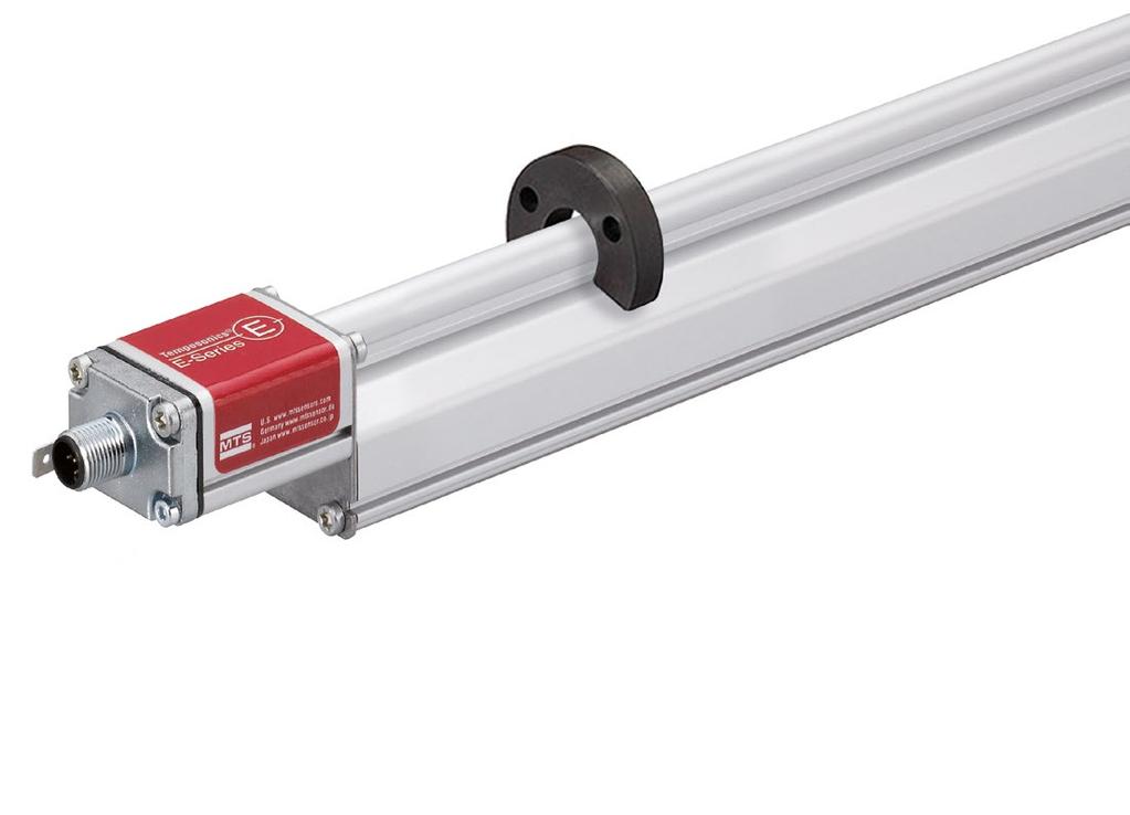
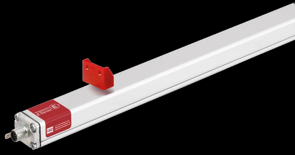
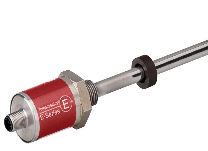
6 3. Identification Nameplate (e.g. E-Series EP CANopen) Output Connection type Stroke length (e.g. 600 mm) Sensor model Baud rate Resolution Multi-position measurement Approvals and certificates You will find approvals and certificates in the sensor specific operation manuals. Part no. Serial number EP00600MD341C304241Z02 FNr.: Year Week 3.1 Temposonics E-Series EH (rod sensor) Sensor electronics housing Pressure-proof rod with sensor element Position magnet (Ring-, U- or block magnet) Available outputs: Analog Start / Stop SSI CANopen IO-Link Threaded flange (M g or ¾"-16 UNF-3A) Connector / cable outlet 3.2 Temposonics E-Series EP (profile sensor) Sensor profile with sensor element Position magnet (Magnet slider, U- or block magnet) Sensor electronics housing Available outputs: Analog Start / Stop SSI CANopen IO-Link Ground lug Connector outlet Mounting clamp Manuals, Software & 3D Models available at: I 6 I
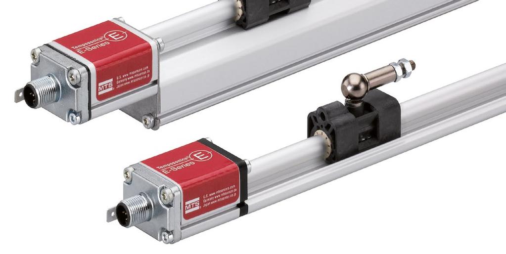
7 3.3 Temposonics E-Series EL (ultra low profile sensor) Sensor profile with sensor element Position magnet (Magnet slider or block magnet) Sensor electronics housing Available outputs: Analog Start / Stop SSI CANopen IO-Link Mounting clamp Ground lug Connector outlet 3.4 Temposonics E-Series EP2 (smooth profile sensor) Sensor electronics housing Position magnet (Block magnet) Mounting clamp Available outputs: Analog Start / Stop SSI CANopen IO-Link Sensor profile with sensor element Connector outlet Ground lug 3.5 Temposonics E-Series ER (rod & cylinder housing) Sensor profile with sensor element Connector outlet Available outputs: Analog Start / Stop SSI CANopen IO-Link Mounting clamp Adjustable rod end Manuals, Software & 3D Models available at: I 7 I
8 4. Installation & mounting 4.1 Sensor mounting Rod sensors E-Series EH Fix the sensor rod via threaded flange. Note the fastening torque of 50 Nm. Seat the flange contact surface completely on the cylinder mounting surface The cylinder manufacturer determines the pressureresistant gasket (copper gasket, O-ring, etc.). The position magnet should not grind on the sensor rod. The piston rod drilling (Ø 10 mm rod: Ø 13 mm ( Ø 0.52 in.) borehole / Ø 7 mm rod: Ø 10 mm ( Ø 0.4 in.) borehole) depends on the pressure and piston speed. Adhere to the information relating to operating pressure. Protect the sensor rod against wear. For detailed mounting instructions see operation manual. Sensors with stroke lengths 1 meter ( 3.3 ft) Support horizontally installed sensors with a stroke length from 1 meter (3.3 ft) mechanically at the rod end. Without the use of a support, rod and position magnet may be damaged. A false measurement result is also possible. Longer rods require evenly distributed mechanical support over the entire length (e.g. part no ). Use an U-magnet for measurement. Profile sensors E-Series EP / EL / ER / EP2 The sensor is fitted on a flat machine surface using mounting clamps. A length-dependent number of these clamps are delivered with the sensor and must be distributed over the profile at regular distances. For fastening, we recommend using M5 20 screws (according to DIN 6912) that should be tightened with a fastening torque of 5 Nm. Mounting clamps Screw: M5 20 (DIN 6912) Fastening torque: 5 Nm Do not raise up the ER sensor, if the lifting rod is extended. It causes serious damage Sensor support (for sensors with stroke lengths 1 meter ( 3.3 ft)) U-magnet Sensor rod Non-magnetic fixing clip I 8 I
9 4.2 Magnet installation Typical use of magnets Ring magnet For: EH Rotationally symmetrical magnetic field Concentric mounting of U-magnet Air gap: 1.75 ±1 (0.07 ±0.04) 2 M4 1 U-magnet For: EH & EP Height tolerances can be compensated Block magnet Magnet slider For: EP, EL, EP2 & EH The magnet can be lifted off Height tolerances can be compensated For: EP & EL The magnet is guided through the profile The distance between the magnet and the waveguide is strictly defined Easy coupling via the ball joint Mounting ring magnets, U-magnets & block magnets Install the magnet using non-magnetic material for mounting device, screws, spacers etc.. The magnet must not grind on the sensor rod. Alignment errors are compensated via the air gap. Permissible surface pressure: Max. 40 N/mm 2 (only for ring magnets and U-magnets) Fastening torque for M4 screws: 1 Nm; use washers, if necessary Minimum distance between position magnet and any magnetic material has to be 15 mm (0.6 in.). If no other option exists and magnetic material is used, observe the specified dimensions. Mount ring magnets and U-magnets concentrically. Mount block magnets centrically over the sensor rod or the sensor profile. Do not exceed the maximum acceptable gap. Take care to mount the sensor in an axially parallel position to avoid damage of the carriage, magnet and sensor rod. Centered mounting of block magnet 1 U-magnet 2 Non-magnetic mounting device and screws Magnet mounting with magnetic material When using magnetic material the dimensions must be observed. A. If the position magnet aligns with the drilled piston rod B. If the position magnet is set further into the drilled piston rod, install another non-magnetic spacer above the magnet Magnet mounting with magnetic material A Magnet 2 1 Magnetic material Null zone, depends on sensor model 2 3 Magnet Distance between position magnet and any magnetic material ( 15 mm ( 0.6 in.)) Non-magnetic spacer ( 5 mm ( 0.2 in.)) Recommendation: 8 mm (0.31 in.) B 2 M4 1 8 ±2 (0.31 ±0.08) Air gap: 3 ±2 (0.12 ±0.08) Sensor element 1 Block magnet 2 Non-magnetic mounting device and screws Controlling design dimensions are in millimeters and measurements in ( ) are in inches I 9 I
10 4.3 Mounting dimensions of E-Series Consider the start and end positions of the position magnets during the installation. To ensure that the entire stroke length E-Series EH with ring- / U-magnet is electrically usable, the position magnet must be mechanically mounted as follows. E-Series EP with block magnet Start position 51 (2.01) End position 63.5 (2.5) Start position 32.5 (1.29) End position 70.5 (2.78) E-Series EH with block magnet E-Series EL with magnet slider S / N / V / G Start position 48.5 (1.91) End position 66 (2.6) Start position 19 (0.75) End position 84 (3.3) E-Series EP with magnet slider S / N / V / G E-Series EL with block magnet Start position 19 (0.75) End position 84 (3.3) Start position 32.5 (1.29) End position 70.5 (2.78) E-Series EP with U-magnet E-Series EP2 with block magnet Start position 35 (1.38) End position 68 (2.68) Start position 73 (2.87) End position 73 (2.87) Manuals, Software & 3D Models available at: The mounting position of the sensor is arbitrary. Controlling design dimensions are in millimeters and measurements in ( ) are in inches I 10 I
11 4.4 Multi-position measurement distances Multi-position measurement with E-Series EH, EP, EL and EP2 sensors with Analog and CANopen output is possible with a simultaneous measuring up to 2 positions. E-Series EH with ring- / U-magnet 75 ( 3) The stroke length influences the maximum number of magnets. Note the minimum distance between the magnets. E-Series EH with block magnet 75 ( 3) E-Series EP with magnet slider S / N / V / G 75 ( 3) E-Series EP with U-magnet 75 ( 3) E-Series EP with block magnet E-Series EL with magnet slider S / N / V / G 75 ( 3) 75 ( 3) E-Series EL with block magnet E-Series EP2 with block magnet 75 ( 3) 75 ( 3) Use magnets of the same type for multi-position measurement, e.g. 2 U-magnets (part no ). Manuals, Software & 3D Models available at: Controlling design dimensions are in millimeters and measurements in ( ) are in inches I 11 I
12 5. Electrical connections Placement of installation and cabling have decisive influence on the sensor s electromagnetic compatibility (EMC). Hence correct installation of this active electronic system and the EMC of the entire system must be ensured by using suitable metal connectors, shielded cables and grounding. Overvoltages or faulty connections can damage its electronics despite protection against wrong polarity. Connect the sensor electronics housing to machine ground. Ground sensor types EP, EL, ER and EP2 via ground lug as shown. Ground the sensor type EH via thread. Sensor grounding 1. Do not mount the sensors in the area of strong magnetic or electric noise fields. 2. Never connect / disconnect the sensor when voltage is applied. Instructions for connection Use low-resistant twisted pair and shielded cables. Connect the shield to ground externally via the controller equipment. Keep control and sign leads separate from power cables and sufficiently far away from motor cables, frequency inverters, valve lines, relays, etc.. Use only connectors with metal housing and connect the shielding to the connector housing. Connect the cable clamps to function as a ground. Keep the connection surface at both shielding ends as large as possible. Keep all non-shielded leads as short as possible. Keep the earth connection as short as possible with a large cross section. Avoid ground loops. With potential differences between machine and electronics earth connections, no compensating currents are allowed to flow across the cable shielding. Recommendation: Install potential compensating leads with large cross section, or use cables with separate double shielding, and connect only one end of the shield. Use only stabilized power supplies in compliance with the specified connecting values. I 12 I
13 5.1 Analog 5.2 Start / Stop D34 M12 male connector (A-coded) View on sensor Pin Function VDC ( 15 / +20 %) 2 Output 1 3 DC Ground (0 V) 4 Output 2 5 DC Ground EH with cable outlet (EHX / ETX) Cable Color Function GY Output 1 PK GND (Signal) YE Output 2 GN Not connected BN +24 VDC ( 15 / +20 %) WH DC Ground (0 V) D84 M12 male connector (A-coded) View on sensor Pin Function 1 Start (+) 2 Start ( ) 3 Stop (+) 4 Stop ( ) 5 Not connected 6 Not connected VDC ( 15 / +20 %) 8 DC Ground (0 V) EH with cable outlet (EHX / ETX) Cable Color Function GY Stop ( ) PK Stop (+) YE Start (+) GN Start ( ) BN +24 VDC ( 15 / +20 %) WH DC Ground (0 V) I 13 I
14 5.3 SSI D84 M12 male connector (A-coded) View on sensor Pin Function 1 Clock (+) 2 Clock ( ) 3 Data (+) 4 Data ( ) 5 Not connected 6 Not connected VDC ( 15 / +20 %) 8 DC Ground (0 V) EH with cable outlet (EHX / ETX) Cable Color Function GY Data ( ) PK Data (+) YE Clock (+) GN Clock ( ) BN +24 VDC ( 15 / +20 %) WH DC Ground (0 V) 5.4 CANopen D34 M12 male connector (A-coded) IO-Link D44 M12 male connector (A-coded) View on sensor 2 View on sensor Pin Pin Function 1 Shield VDC ( 15 / +20 %) 3 DC Ground (0 V) 4 CAN_H 5 CAN_L EH with cable outlet (EHX / ETX) Cable Color Function GY CAN_L PK CAN_H YE Not connected GN Not connected BN +24 VDC ( 15 / +20 %) WH DC Ground (0 V) Function VDC (+25 %) 2 DI / DQ 3 DC Ground (0 V) 4 C / Q I 14 I
15 Notes I 15 I
16 Document Part Number: Revision C (EN) 05/2017 LOCATIONS USA MTS Systems Corporation Sensors Division 3001 Sheldon Drive Cary, N.C , USA Tel Fax info.us@mtssensors.com JAPAN MTS Sensors Technology Corp. 737 Aihara-machi, Machida-shi, Tokyo , Japan Tel Fax info.jp@mtssensors.com GERMANY MTS Sensor Technologie GmbH & Co. KG Auf dem Schüffel Lüdenscheid, Germany Tel Fax info.de@mtssensors.com CHINA MTS Sensors Room 504, Huajing Commercial Center, No. 188, North Qinzhou Road Shanghai, China Tel Fax info.cn@mtssensors.com LEGAL S MTS, Temposonics and Level Plus are registered trademarks of MTS Systems Corporation in the United States; MTS SENSORS and the MTS SENSORS logo are trademarks of MTS Systems Corporation within the United States. These trademarks may be protected in other countries. All other trademarks are the property of their respective owners. Copyright 2017 MTS Systems Corporation. No license of any intellectual property rights is granted. MTS reserves the right to change the information within this document, change product designs, or withdraw products from availability for purchase without notice. Typographic and graphics errors or omissions are unintentional and subject to correction. Visit for the latest product information. FRANCE MTS Systems SAS Zone EUROPARC Bâtiment EXA 16 16/18, rue Eugène Dupuis Creteil, Frankreich Tel Fax info.fr@mtssensors.com ITALY MTS Systems Srl Sensor Division Via Camillo Golgi, 5/ Gussago (BS), Italy Tel Fax info.it@mtssensors.com Reg.-No QM08
Temposonics Magnetostrictive Linear Position Sensors. Temposonics GB-Series Brief Instructions
 Temposonics Magnetostrictive Linear Position Sensors Table of contents. Introduction...3 2. Safety instructions...4 2. Intended use...4 2.2 Forseeable misuse...4 2.3 Installation, commissioning and operation...5
Temposonics. MH-Series Analog Redundant. Absolute, Non-Contact Positions Sensors. Temposonics MT Measuring length mm
 Temposonics Absolute, Non-Contact Positions Sensors MH-Series Document Part Number 551218 Revision F Temposonics MT Measuring length 50-2500 mm Redundant Sensor for Mobile Hydraulics Redundant Sensor System
Temposonics. Magnetostrictive Linear Position Sensors. TH CANbus Data Sheet
 Temposonics ostrictive Linear Position Sensors TH CANbus ATEX / IECEx / CEC / NEC / EAC Ex certified / Japanese approval Continuous operation under harsh industrial conditions Flameproof / Explosionproof
Temposonics ATEX. Magnetostrictive Linear Position Sensors. DATA SHEET High Pressure Housing (HPH) The Measurable Difference
 The Measurable Difference") Temposonics Magnetostrictive Linear Position Sensors DATA SHEET (HPH) ATEX The Measurable Difference PRECISION POSITION MEASUREMENT HPH This (HPH) is ATEX-IECEx as well as UL and cul approved for use in
Temposonics Magnetostrictive Linear Position Sensors DATA SHEET (HPH) ATEX The Measurable Difference PRECISION POSITION MEASUREMENT HPH This (HPH) is ATEX-IECEx as well as UL and cul approved for use in
Temposonics. Magnetostrictive Linear Position Sensors. R-Series Profinet IO RT Operation Manual
 Temposonics Magnetostrictive Linear Position Sensors R-Series Profinet IO RT Table of contents 1. Introduction... 3 1.1 Purpose and use of this manual... 3 1.2 Used symbols and warnings... 3 2. Safety
Temposonics. Magnetostrictive Linear Position Sensors. TH Analog Data Sheet
 Temposonics ostrictive Linear Position Sensors TH Analog ATEX / IECEx / CEC / NEC / EAC Ex certified / Japanese approval Continuous operation under harsh industrial conditions Flameproof / Explosionproof
Temposonics. Magnetostrictive Linear Position Sensors. MH-Series Flexible MH Installation Manual
 Temposonics Magnetostrictive Linear Position Sensors MH-Series Flexible MH Operation Manual Table of contents 1. Introduction... 3 1.1 Purpose and use of this manual... 3 1.2 Used symbols and warnings...
Temposonics. Magnetostrictive Linear Position Sensors. TH Analog SIL 2 capable Data Sheet
 Temposonics ostrictive Linear Position Sensors TH Analog SIL 2 capable ATEX / IECEx / CEC / NEC / EAC Ex certified / Japanese approval Continuous operation under harsh industrial conditions Flameproof
Level Plus. Magnetostrictive Liquid Level Transmitters with Temposonics Technology. LP-Series SE Replacement Installation Manual
 Level Plus Magnetostrictive Liquid Level Transmitters with Temposonics Technology LP-Series SE Replacement 1. Contact information United States General Tel: +1-919-677-0100 Fax: +1-919-677-2343 E-mail:
Temposonics. Magnetostrictive Linear Position Sensors. GB-Series Analog Operation Manual
 Temposonics Magnetostrictive Linear Position Sensors GB-Series Analog Table of contents 1. Introduction...3 1.1 Purpose and use of this manual...3 1.2 Used symbols and warnings...3 2. Safety instructions...3
Temposonics. Magnetostrictive Linear Position Sensors. MHRM Analog Data Sheet. For embedded or externally threaded installation
 Temposonics ostrictive Linear Position Sensors MHRM Analog For embedded or externally threaded installation Sensor rod with Ø 7 mm or Ø 0 mm Resolution: ±0. mm typ. Compliant with EN 50-3- MEASURING TECHNOLOGY
Temposonics. Absolute, Non-Contact Position Sensors. OPERATION MANUAL R-Serie Analog. The Measurable Difference
 Temposonics Absolute, Non-Contact Position Sensors OPERATION MANUAL R-Serie Analog The Measurable Difference Table of contents 1. Introduction...2 1.1 Purpose and use of this manual... 2 1.2 Used symbols
Temposonics. Magnetostrictive Linear Position Sensors. R-Series Ethernet/IP TM Operation Manual
 Temposonics ostrictive Linear Position Sensors R-Series Ethernet/IP TM Table of contents 1. Introduction... 2 1.1 Purpose and use of this manual... 2 1.2 Used symbols and warnings... 2 2. Safety instructions...
Temposonics. Magnetostrictive Linear Position Sensors. E-Series IO-Link Operation Manual
 Temposonics Magnetostrictive Linear Position Sensors E-Series IO-Link Table of contents 1. Introduction... 3 1.1 Purpose and use of this manual... 3 1.2 Used symbols and warnings... 3 2. Safety instructions...
Temposonics. Magnetostrictive Linear Position Sensors. MH-Series MH5 Analog Data Sheet
 Temposonics Magnetostrictive Linear Position Sensors MH-Series MH5 Analog Linearity < 0.04 % F.S. Resolution typ. ±0.1 mm Stainless steel housing 1. Product description and technology Temposonics sensors
Temposonics. Absolute, Non-Contact Position Sensors. MH Series. Temposonics MB Analog. Technical Data / Description
 Temposonics Absolute, Non-Contact Position Sensors MH Series Technical Data / Description Document No. 551220 Revision E Compact Sensor for Mobile Hydraulics Linear, absolute Measurement in Hydraulic Cylinders
Temposonics. G-Series Analog or Start/Stop. Absolute, Non-Contact Position Sensors. Temposonics GP and GH Stroke length mm depends on output
 Temposonics Absolute, Non-Contact Position Sensors G-Series Temposonics GP and GH Stroke length 50...7600 mm depends on output C GP GH Position ~ Time Output signal indicating to magnet's position Sensor
Temposonics Magnetostrictive, Absolute, Non-contact Linear-Position Sensors
 Temposonics Magnetostrictive, Absolute, Non-contact Linear-Position Sensors E-Series Model EH Synchronous Serial Interface (SSI) Output Data Sheet SENSORS Document Part Number: 551314 Revision B Model
R-Series Rod Model RS. Data Sheet. Model RS Rod-style sensor with IP68/IP69K Super Shield Housing. Interrogation Return wire.
 Temposonics Magnetostrictive, Absolute, Non-contact Linear-Position Sensors R-Series Rod Model RS SENSORS Document Part Number 551251 Revision A Data Sheet Model RS Rod-style sensor with IP68/IP69K Super
Temposonics. E-Series Analog + Start / Stop. Magnetostrictive Position Sensors. Temposonics EP Measuring range mm / mm SENSORS
 Temposonics Magnetostrictive Position Sensors m SENSORS E-Series Temposonics EP Measuring range 50-1500 mm / 50-3250 mm... innovative Sensor-Parameter Handling Linear, Absolute Measurment Contactless Sensing
Temposonics Magnetostrictive, Absolute, Non-contact Linear-Position Sensors
 Temposonics Magnetostrictive, Absolute, Non-contact Linear-Position Sensors M-Series Mobile Hydraulic in-cylinder Sensor Model MH CANopen, CAN J1939 Output Data Sheet SENSORS Document Part Number 551027
Temposonics. Magnetostrictive, Absolute, Non-contact Linear-Position Sensors. R-Series Models RP and RH DeviceNet Output.
 Temposonics Magnetostrictive, Absolute, Non-contact Linear-Position Sensors R-Series Models RP and RH DeviceNet Output SENSORS Document Part Number 550651 Revision F Data Sheet Model RP Profile-style position
Temposonics. M-Series PWM. Absolute, Non-Contact Position Sensors. Temposonics MH Measuring Length mm. Document Number Revision B
 Temposonics Absolute, Non-Contact Position Sensors M-Series Temposonics MH Measuring Length 50-2500 mm Document Number 551225 Revision B Compact Sensor for Mobile Hydraulics Linear, absolute Measurement
CANBUS G. Up to mm ( in.) < ± 0.01% of full stroke or ± 0.04 mm ( in.), whichever is greater*
 < ± 0.01% of full stroke or ± 0.04 mm ( in.), whichever is greater*") 27295 8/11/03 T 7:42 AM Page 1 E M P O S O N I C S R S E R I E S CANBUS 550541 G P r o d u c t S p e c i f i c a t i o n s PARAMETER S P E C I F I C AT I O N Measured Variable: Resolution: Non-Linearity:
27295 8/11/03 T 7:42 AM Page 1 E M P O S O N I C S R S E R I E S CANBUS 550541 G P r o d u c t S p e c i f i c a t i o n s PARAMETER S P E C I F I C AT I O N Measured Variable: Resolution: Non-Linearity:
Temposonics. G-Series Analog Redundant. Magnetostrictive Position Sensors. Redundancy for enhanced safety
 Temposonics Magnetostrictive Position Sensors m SENSORS G-Series Redundant Temposonics GT2 and GT3 Measuring length 25-1500 mm Redundancy for enhanced safety Up to 3 totally separated, independent measuring
SSI. Synchronous Serial Interface
 T E M P O S O N I C S R S E R I E S SSI Synchronous Serial Interface P r o d u c t S p e c i f i c a t i o n s PARAMETER Measured Variable: Resolution: Non-Linearity: SPECIFICATION Displacement Up to 0.002
Temposonics. M-Series Analog Redundant. Absolute, Non-Contact Positions Sensors. Temposonics MT Measuring length mm
 Temposonics Absolute, Non-Contact Positions Sensors M-Series Document Part Number 551218 Revision D Temposonics MT Measuring length 50-1500 mm Redundant Sensor for Mobile Hydraulics Redundant Sensor System
Temposonics. M-Series Analog. Magnetostrictive Position Sensors. Temposonics MH Measuring length mm SENSORS
 Temposonics Magnetostrictive Position Sensors m SENSORS M-Series Temposonics MH Measuring length 50-2500 mm Compact Sensor for Mobile Hydraulics Linear, Absolute Measurement in Hydraulic Cylinders Contactless
Temposonics Magnetostrictive, Absolute, Non-contact Linear-Position Sensors
 Temposonics Magnetostrictive, Absolute, Non-contact Linear-Position Sensors MH-Series Model MB Mobile Hydraulic Sensor with Analog Output Data Sheet SENSORS Document Part Number 551284 Revision A MH-Series
Temposonics. Magnetostrictive Linear Position Sensors. DATA SHEET GBS Analog
 Temposonics Magnetostrictive Linear Position Sensors DATA SHEET GBS Analog High pressure resistant sensor rod High operating temperature up to 100 C Flat & compact ideal for the valve market The Measurable
ANALOG. PARAMETER SPECIFICATION Measured Variable: Displacement, Velocity (magnitude only) 16 bit or mm, whichever is greater
 16 bit or mm, whichever is greater") T E M P O S O N I C S I I I ANALOG P r o d u c t S p e c i f i c a t i o n s F e a t u r e s Superior resolution and repeatability Absolute displacement and velocity measurement Modular, non-contacting
T E M P O S O N I C S I I I ANALOG P r o d u c t S p e c i f i c a t i o n s F e a t u r e s Superior resolution and repeatability Absolute displacement and velocity measurement Modular, non-contacting
Temposonics. M-Series Analog. Absolute, Non-Contact Position Sensors. Temposonics MH Measuring length mm. Compact Sensor for Mobile Hydraulics
 Temposonics Absolute, Non-Contact Position Sensors M-Series Temposonics MH Measuring length 50-2500 mm Compact Sensor for Mobile Hydraulics Linear, Absolute Measurement in Hydraulic Cylinders Contactless
Temposonics. Magnetostrictive, Absolute, Non-contact Linear-Position Sensors. R-Series Models RP and RH Ethernet POWERLINK.
 Temposonics Magnetostrictive, Absolute, Non-contact Linear-Position Sensors R-Series Models RP and RH Ethernet POWERLINK SENSORS Document Part Number 551191 Revision A Data Sheet Model RP Profile-style
Temposonics GENERATION THE NEW I AM. Magnetostrictive Linear Position Sensors. Temposonics R-Series V Profinet RT & IRT Operation Manual
 Temposonics Magnetostrictive Linear Position Sensors Temposonics R-Series V Profinet RT & IRT I AM V THE NEW GENERATION Table of contents 1. Introduction... 3 1.1 Purpose and use of this manual... 3 1.2
Temposonics. M-Series Analogue / SIL2* Absolute, Non-Contact Position Sensors. Temposonics MH Measuring Length mm
 Temposonics Absolute, Non-Contact Position Sensors M-Series / SIL2* Temposonics MH Measuring Length 50-2500 mm Compact Sensor for Mobile Hydraulics Linear, absolute Measurement in Hydraulic Cylinders Non-Contact
Temposonics. R-Series DeviceNet. Magnetostrictive Position Sensors. Intelligent Design. Temposonics RP and RH Measuring length mm SENSORS
 Temposonics Magnetostrictive Position Sensors m SENSORS R-Series Temposonics RP and RH Measuring length 25-7600 mm Rugged Industrial Sensor Linear and Absolute Measurement LEDs for Sensor Diagnostic Contactless
Temposonics. Magnetostrictive Linear-Position Sensors. R-Series Model RP and RH Sensors Synchronous Serial Interface (SSI) Output D
 Output D") Temposonics Magnetostrictive Linear-Position Sensors R-Series Model RP and RH Sensors Synchronous Serial Interface (SSI) Output Product Specification 550989 D Rugged industrial sensor Linear, absolute
Temposonics Magnetostrictive Linear-Position Sensors R-Series Model RP and RH Sensors Synchronous Serial Interface (SSI) Output Product Specification 550989 D Rugged industrial sensor Linear, absolute
Temposonics Magnetostrictive, Absolute, Non-contact Linear-Position Sensors
 Temposonics Magnetostrictive, Absolute, Non-contact Linear-Position Sensors MH-Series Mobile Hydraulic in-cylinder Sensor Model MH Analog Output Data Sheet SENSORS Document Part Number 550824 Revision
Temposonics. Absolute, Non-Contact Position Sensors. MH Series. Temposonics MH Analog /Digital. Technical Data / Description
 Temposonics Absolute, Non-Contact Position Sensors MH Series Temposonics MH Analog /Digital Document Part Number 551308 Revision B Technical Data / Description Compact sensor for mobile hydraulics Designed
PRODUCT SELECTOR GUIDE
 TEMPOSONICS AND HALL EFFECT POSITION SENSORS FOR MOBILE APPLICATIONS PRODUCT SELECTOR GUIDE 2 TABLE OF CONTENTS COMPANY 5 MEASURING TECHNOLOGIES 6 M12 CONNECTOR SYSTEM 7 SERIES QUICK GUIDE 9 MH-SERIES
Temposonics. Magnetostrictive Linear Position Sensors
 Temposonics Magnetostrictive Linear Position Sensors TH Analog ATEX / IECEx / CEC / NEC / EAC Ex certified / Japanese approval / Safety SIL 2 capable Table of contents 1. Introduction...3 1.1 Purpose and
PRODUCT SELECTOR GUIDE
 TEMPOSONICS AND HALL EFFECT POSITION SENSORS FOR MOBILE APPLICATIONS PRODUCT SELECTOR GUIDE 2 MEETING THE CHALLENGES OF MOBILE APPLICATIONS Agricultural Construction Forestry Mining Handling & Logistics
Temposonics. Magnetostrictive Linear Position Sensors
 Temposonics Magnetostrictive Linear Position Sensors TH Analog ATEX / IECEx / CEC / NEC / KCs / EAC Ex certified / Japanese approval / Safety SIL 2 capable Table of contents 1. Introduction...3 1.1 Purpose
Temposonics. Absolute, Non-Contact Position Sensors. MH Series. Temposonics MH 200. Technical Data / Description. Compact sensor for mobile hydraulics
 Temposonics Absolute, Non-Contact Position Sensors MH Series Temposonics Technical Data / Description Document Part Number 551405 Revision A Compact sensor for mobile hydraulics Designed for the mobile
L E V E L P L U S M - S E R I E S ANALOG
 L E V E L P L U S M - S E R I E S ANALOG P r o d u c t S p e c i f i c a t i o n s NEMA 4X Housing, Sanitary Gauge Single Chamber Housing, Rigid Gauge Dual Chamber Housing, Flexible Gauge Level Plus M-Series
Your Global Automation Partner. LTX Linear Position Sensors with SSI Interface. Operating instructions
 Your Global Automation Partner LTX Linear Position Sensors with SSI Interface Operating instructions Contents 2 Hans Turck GmbH & Co. KG T +49 208 4952-0 F +49 208 4952-264 more@turck.com www.turck.com
Temposonics. Temposonics R-Series. Instruction Manual. EtherCAT Interface. Absolute, Non-Contact Position Sensors. Rod model Temposonics-RH
 Temposonics Absolute, Non-Contact Position Sensors m SENSORS Rod model Temposonics-RH Profile model Temposonics-RP Temposonics R-Series EtherCAT Interface Content 1. Safety and operating instructions 2.
Exchange of rollers from the XTS-Mover
 Service documentation for AT901-0050-0550 and AT9011-00x0-0550 Version: Date: 1.0 0.10.017 Table of contents Table of contents 1 Foreword... 5 1.1 Notes on the documentation... 5 1. Documentation issue
Operating instructions Safety sensor BNS About this document. Content. 6 Disassembly and disposal 6.1 Disassembly Disposal...
 Safety sensor BNS Disassembly and disposal. Disassembly..... Disposal... EU Declaration of conformity Operating instructions.............pages to Original x.000 / 0.0 / v.a. - 09009- / J / 0-0-0 / AE-Nr.
Angle sensor AN2 series 30
 Angle sensor AN2 series 30 RE 95143 Edition: 09.2016 Replaces: 06.2015 Hall-effect sensor for angular measurement Features Angle sensor element based on the Hall-effect principle Shaft can be turned through
Contamination switch VS
 Contamination switch VS RE 95148 Issue: 12.2015 Replaces: 09.2015 For detecting metallic impurities in oil Inhalt Ordering code 2 Description 2 Technical data 2 Connection 3 Dimensions 3 Safety instructions
Assembly and Maintenance Manual Type RSBW
 Assembly and Maintenance Manual Type RSBW Hatschekstr. 36 69126 Heidelberg Germany Tel +49(0)6221 30470 Tel +49(0)6221 304731 info@stieber.de www.stieber.de Stieber Clutch Date of issue: 16/03/2017 GB
Temposonics Magnetostrictive Linear-Position Sensors
 Temposonics ostrictive Linear-Position Sensors Sizing and Applying ostrictive Linear-Position Sensors Technical Paper SENSORS 551045 E ostrictive Linear-Position sensor with sensing rod and position magnet
Assembly and Maintenance Manual Type ASNU
 Assembly and Maintenance Manual Type ASNU Hatschekstr.36 69126 Heidelberg Germany Tel +49(0)6221 30470 Fax +49(0)6221 304731 info@stieber.de www.stieber.de Date of issue: 30.05.2018 GB Revision: 0 U:\EngUsers\!ProduktDoku\1AAA_Einbauerklaerung_Wartungsanleitung_Konformitaetserklaerung\1AAA_Wartungsanleitungen\Orginal_Worddatei\_ASNU.docx
A company of ThyssenKrupp Elevator. ThyssenKrupp Aufzugswerke. Operating Manual. Oil buffer
 A company of ThyssenKrupp Elevator ThyssenKrupp Aufzugswerke Operating Manual Oil buffer OPERATING MANUAL Printer s imprint All rights reserved. Copyright by: THYSSENKRUPP AUFZUGSWERKE GMBH P.O. box 23
NEOTECHA NTB-NTC BALL VALVES INSTALLATION AND MAINTENANCE INSTRUCTIONS
 Before installation these instructions must be fully read and understood 2 SAFETY Please also read through these notes carefully. 2.1 General potential danger due to: a. Failure to observe the instructions
Assembly and Maintenance Manual Type AS
 Assembly and Maintenance Manual Type AS Hatschekstr.36 69126 Heidelberg Germany Tel +49(0)6221 30470 Fax +49(0)6221 304731 info@stieber.de www.stieber.de Date of issue: 30.05.2018 GB Revision: 0 U:\EngUsers\!ProduktDoku\1AAA_Einbauerklaerung_Wartungsanleitung_Konformitaetserklaerung\1AAA_Wartungsanleitungen\Orginal_Worddatei\_AS.docx
SPARKSCAN1 HIGH VOLTAGE CLAMP OPERATING MANUAL
 SPARKSCAN1 HIGH VOLTAGE CLAMP OPERATING MANUAL MOTORTECH Tools & Test Equipment for Ignition Systems P/N 01.10.019 Rev. 01/2013 Copyright Copyright 2012 MOTORTECH GmbH. All rights reserved. Distribution
Pressure relief valve
 Pressure relief valve Operating manual Series DHV 712 Version BA-2015.10.20 EN Print-No. 300 510 TR MA DE Rev001 ASV Stübbe GmbH & Co. KG Hollwieser Straße 5 32602 Vlotho Germany Phone: +49 (0) 5733-799-0
User Guide. Lubricus Lubrication System LUB-D1/LUB-D2/LUB-D3/LUB-D4 (24 VDC)
") User Guide Lubricus Lubrication System LUB-D1/LUB-D2/LUB-D3/LUB-D4 (24 VDC) version 04/2013 Content General Information 3 Warning 3 Scope of Supply 3 Overview 3 General safety details 4 Intended use 4
User Guide Lubricus Lubrication System LUB-D1/LUB-D2/LUB-D3/LUB-D4 (24 VDC) version 04/2013 Content General Information 3 Warning 3 Scope of Supply 3 Overview 3 General safety details 4 Intended use 4
Safety Shock Absorbers SCS33 to SCS64
 Safety Shock Absorbers SCS33 to SCS64 1 Operating Instruction SCS33-25EU SCS33-50EU SCS45-25EU SCS45-50EU SCS45-75EU Rod Button SCS64-50EU SCS64-100EU SCS64-150EU Integrated Rod Seals Main Bearing Content
SCOPELITE TIMING LIGHT OPERATING MANUAL
 SCOPELITE TIMING LIGHT OPERATING MANUAL MOTORTECH Tools & Test Equipment for Ignition Systems P/N 01.10.020-EN Rev. 11/2015 Copyright Copyright 2015 MOTORTECH GmbH. All rights reserved. Distribution and
These installation and maintenance instructions must be read in full and completely understood before the installation!
 These installation and maintenance instructions must be read in full and completely understood before the installation! 1. General information on the installation and maintenance instructions These instructions
BODAS Pressure sensor PR3 series 10
 BODAS Pressure sensor PR3 series 10 RE 95155 Edition: 04.2014 Replaces: 12.2013 Measurement ranges to 25, 50, 160, 200, 250, 400, 600 bar Ratiometric output signal 0.5 to 4.5 V with 5 V supply voltage
Part No Rev. E
 l T e m p o s o n i c s P o s i t i o n S e n s o r s a n d S y s t e m s Part No. 550033 Rev. E T emposonics II Position Sensors Installation & Instruction Manual 11-98 550055 Revision E GENERAL INFORMATION
Operating instructions Actuator and Emergency exit AZ/AZM 200-B30 AZ/AZM 201-B About this document. Content
 1. About this document Operating instructions............pages 1 to 10 Original 1.1 Function This operating instructions manual provides all the information you need for the mounting, set-up and commissioning
Angle Sensor WS1. RE Edition: Replaces:
 Angle Sensor WS1 RE 95140 Edition: 06.2017 Replaces: 07.2007 Hall-effect semiconductor elements and integrated amplifiers Robust plastic housing with moulded plug Metal inner housing and line filter for
Tina 4A Connection block
 Original instructions Tina 4A Connection block Instructions valid for versions of the product from ver. H ABB Jokab Safety Varlabergsvägen 11, SE-434 39 Kungsbacka, Sweden www.abb.com/jokabsafety Read
Mini slide EGSC-BS-KF. Operating instructions b [ ]
![Mini slide EGSC-BS-KF. Operating instructions b [ ]](/thumbs/87/95253800.jpg "Mini slide EGSC-BS-KF. Operating instructions b [ ]") Mini slide EGSC-BS-KF en Operating instructions 8081968 2017-11b [8081970] Translation of the original instructions EGSC-BS-KF-EN Identification of hazards and instructions on how to prevent them: Danger
Mini slide EGSC-BS-KF en Operating instructions 8081968 2017-11b [8081970] Translation of the original instructions EGSC-BS-KF-EN Identification of hazards and instructions on how to prevent them: Danger
73000 Series Masoneilan* Sweep Angle Control Valves Models XX-73471
 GE Oil & Gas 73000 Series Masoneilan* Sweep Angle Control Valves Models XX-73471 Instruction Manual GE Data Classification: Public THESE INSTRUCTIONS PROVIDE THE CUSTOMER/OPERATOR WITH IMPORTANT PROJECT-SPECIFIC
DLT-U1100 UPS Uninterruptible Power Supply Manual V1.00. Industrial PCs applied in
 Industrial PCs applied in / Logistics and Warehouse / Heavy Duty / Fleet Management / Stationary and Automation DLT-U1100 UPS Uninterruptible Power Supply Manual V1.00 IMPORTANT: Read this manual carefully.
HST -LS Interlocking device (Translation of Original Manual)
") Installation and Operating Manual for Components HST -LS Interlocking device (Translation of Original Manual) HST-LS Ident.-No.: 10268 HST-LS Ident.-No.: 10269 HST-LS, pictured Ident-Nr. 10269 The image
Installation and Operating Manual for Components HST -LS Interlocking device (Translation of Original Manual) HST-LS Ident.-No.: 10268 HST-LS Ident.-No.: 10269 HST-LS, pictured Ident-Nr. 10269 The image
Declaration of Conformity as per Directive 97/23/EC
 Declaration of Conformity as per Directive 97/23/EC The manufacturer declares that:, 47906 Kempen, Germany PTFE-lined Rotary plug valves Series 23e, with packing with lever for 90 operation with worm gear
INSTRUCTION MANUAL. I/P Converter DSG BXXY3Z DSG BXXY4Z
 INSTRUCTION MANUAL I/P Converter DSG BXXY3Z DSG BXXY4Z Revision 2.0 3.626 016136 en Page 1/15 Should you have any questions concerning the I/P converter, please contact the Service Department of the Product
Operating Instructions CYR52
 BA01300C/07/EN/02.14 71261315 Products Solutions Services Operating Instructions CYR52 Ultrasonic cleaning Document information Warnings The structure, signal words and safety colors of the signs comply
Installation manual wall-mounted distributor
 EN Installation manual wall-mounted distributor EN 60003233 Issue 11.2016 2016-14-11 Table of contents 1 About this manual 3 1.1 Structure of the warnings 3 1.2 Symbols used 4 1.3 Signal words used 4 2
WATERFLUX 3070 Quick Start
 WATERFLUX 3070 Quick Start Battery powered electromagnetic water meter Electronic Revision ER 4.3.0_ up to ER 4.3.4_ (SW.REV 4.2.2_ up to 4.2.5_) KROHNE CONTENTS WATERFLUX 3070 1 Safety instructions 4
FLENDER ARPEX Plate packs with close-fitting bolt connection. ARW-4 Sizes to Assembly instructions An 4239 en 12/2015.
 FLENDER ARPEX Plate packs with close-fitting bolt connection ARW-4 Sizes 101-4 to 292-4 Assembly instructions FLENDER couplings FLENDER ARPEX Plate packs with close-fitting bolt connection ARW-4 Sizes
SPARK PLUG CLEANING KIT OPERATING MANUAL
 SPARK PLUG CLEANING KIT OPERATING MANUAL Spark Plugs - Tools & Accessories P/N 01.20.002 Rev. 08/2015 Copyright Copyright 2015 MOTORTECH GmbH. All rights reserved. Distribution and reproduction of this
A Member of the. Integrated Metering Technologies
 I n s t a l l a t i o n M a n u a l A Member of the Integrated Metering Technologies 1.0 General and Safety Do not install, operate or maintain this flow meter without reading, understanding and followingthe
Spindle axis ELGC-BS-KF. Operating instructions [ ]
![Spindle axis ELGC-BS-KF. Operating instructions [ ]](/thumbs/87/97202885.jpg "Spindle axis ELGC-BS-KF. Operating instructions [ ]") Spindle axis ELGC-BS-KF en Operating instructions 8067243 2017-01 [8067245] Original instructions Identification of hazards and instructions on how to prevent them: Danger Immediate dangers which can lead
Spindle axis ELGC-BS-KF en Operating instructions 8067243 2017-01 [8067245] Original instructions Identification of hazards and instructions on how to prevent them: Danger Immediate dangers which can lead
Magnetostriction in Automotive Position Measurement
 l MTS Systems Corporation Sensors Division 3001 Sheldon Drive Cary, NC 27513 Phone 919-677-0100, Fax 919-677-0200 TECHNICAL PAPER Part Number: 08-02 M1163 Revision A Magnetostriction in Automotive Position
INSTRUCTION MANUAL RELAY FOR ON LOAD TAP CHANGER APPLICATIONS OR-25 5COR OR25 REV03
 INSTRUCTION MANUAL RELAY FOR ON LOAD TAP CHANGER APPLICATIONS OR-25 5COR469000 OR25 REV03 I II CONTENT: 1 SAFETY 1.1 Safety instructions 2 1.2 Specified applications 2 1.3 Safety notes on the equipment
Printed: Doc-Nr: PUB / / 000 / 00
 ORIGINAL OPERATING INSTRUCTIONS Hilti HTE-P 33 dispenser It is essential that the operating instructions are read before the tool is operated for the first time. Always keep these operating instructions
Bowl Feeder BF10 / BF15 Translation of operating and installation instructions
 Bowl Feeder BF10 / BF15 Translation of operating and installation instructions Copyright by Afag GmbH This operation instruction applies to: Bowl feeder right 12 Bowl feeder left 12 Type Order number BF10
Operating instructions Spray nozzle SDU
 Operating instructions Spray nozzle SDU INDEX Page 1. General... 2 2. Safety... 2 4 A. Nozzles type... 5 B. Nozzles inserts... 5 C. Revision... 5 D. Monitoring... 6 E. Heating... 6 F. Accessories... 6
VARIFUEL MAINTENANCE AND REPAIR INSTRUCTIONS
 VARIFUEL2 140-65 MAINTENANCE AND REPAIR INSTRUCTIONS MOTORTECH Gas Regulation P/N 01.50.008-140-65-EN Rev. 06/2015 Copyright Copyright 2015 MOTORTECH GmbH. All rights reserved. Distribution and reproduction
T1/T2 HYDRAULIC RAM INSTALLATION & SERVICE HANDBOOK
 T1/T2 HYDRAULIC RAM INSTALLATION & SERVICE HANDBOOK SERIAL NUMBER NOTIFICATION The information contained in this document is subject to change without prior notice. Navico UK Ltd. shall not be liable for
Operating instructions
 Operating instructions Digital tank contents indicator DTA 10 DTA 10 DTA 10 0 4.0 m fuel oil 0 3.5 m water Read instructions before using device! Observe all safety information! Keep instructions for future
Safety Shock Absorbers SDH38 to SDH63
 afety hock Absorbers DH38 to DH63 Operating Instruction 1 DH38-50EU DH38-100EU DH38-150EU DH38-0EU DH38-250EU DH38-300EU DH38-350EU DH38-400EU DH38-500EU DH38-600EU DH38-700EU DH38-800EU DH50-100EU DH50-150EU
VARIFUEL MAINTENANCE AND REPAIR INSTRUCTIONS
 VARIFUEL2 200-120 MAINTENANCE AND REPAIR INSTRUCTIONS MOTORTECH Gas Regulation P/N 01.50.008-200-120-EN Rev. 06/2015 Copyright Copyright 2015 MOTORTECH GmbH. All rights reserved. Distribution and reproduction
Bowl feeder BF20 / BF25 / BF30 BF35 / BF40 / BF50
 Bowl feeder BF20 / BF25 / BF30 BF35 / BF40 / BF50 Translation of operating and installation instructions Copyright by Afag GmbH This operation instruction applies to: Type Order number BF20 BF25 BF30 BF35
Sheet n 1 of 20 Doc. n WDMM/02/E MOD. WDMM INSTALLATION, USE AND SERVICE MANUAL. PETROL INSTRUMENTS S.r.l APRILIA (LT) - ITALY
 - ITALY") Sheet n 1 of 20 WATER DRAW/ MASTER METER PETROL COUNTER MOD. WDMM INSTALLATION, USE AND SERVICE MANUAL PETROL INSTRUMENTS S.r.l. - 04011 APRILIA (LT) - ITALY Sheet n 2 of 20 INSTALLATION, USE AND SERVICE
Sheet n 1 of 20 WATER DRAW/ MASTER METER PETROL COUNTER MOD. WDMM INSTALLATION, USE AND SERVICE MANUAL PETROL INSTRUMENTS S.r.l. - 04011 APRILIA (LT) - ITALY Sheet n 2 of 20 INSTALLATION, USE AND SERVICE
BODAS Temperature sensor for fluids TSF
 BODAS Temperature sensor for fluids TSF RE 95180 Issue: 09.2015 Replaces: 04.2015 Temperature measurement of cooling fluids, hydraulic oils or engine oil in vehicles Function The sensor element comprises
INSTALLATION MANUAL XMT MAGNETOSTRICTIVE LEVEL PROBE
 INSTALLATION MANUAL XMT MAGNETOSTRICTIVE LEVEL PROBE INDEX INDEX... 2 REVISION INDEX... 2 INTRODUCTION... 3 GENERAL WARNINGS... 3 DESCRIPTION... 4 MAIN COMPONENTS... 5 MECHANICAL INSTALLATION... 6 INSTALLATION
Installation Instructions. Y-Series Brushless Servo Motor
 Installation Instructions Y-Series Brushless Servo Motor Catalog Number Y-1002-1, Y-1002-2, Y-1003-1, Y-1003-2, Y-2006-1, Y-2006-2, Y-2012-1, Y-2012-2, and Y-3023-2 These installation instructions describe
Bowl feeder WV401-1 / Translation of operating and installation instructions
 Bowl feeder WV401-1 / 402-1 Translation of operating and installation instructions Copyright by Afag GmbH This operation instruction applies to: Bowl feeder WV401-1 Bowl feeder WV402-1 Type 230 V / 50
Operating and Maintenance Manual. for. HADEF overhead crane. as jointed crane TA
 5.52.714.00.1.0 Edition 03.2004 GB Operating and Maintenance Manual for HADEF overhead crane as jointed crane TA Subject to changes. 1 HADEF Table of Contents 1 General Page 3 2 Product description Page
AC 100. Operating instructions Pneumatic Crimper AC 100. Date of issue: 05/2010. Keep for future use!
 Operating instructions Pneumatic Crimper AC 100 Date of issue: 05/2010 Keep for future use! SAFETY SAFETY Basic information The basic prerequisite for ensuring safe use and continuous operation of the
Series 77 & 78. Compact & Modular Valves. solutions. Series 77 - Compact Valves. Series 77 - Sub-D. Series 77 - Fieldbus
 PNEUMATIC valves Series 77 & 78 Compact & Modular Valves Series 77 - Compact Valves Series 77 - LPP770 Series 77 - Sub-D Series 77 - Fieldbus Series 77 - LPP772 Series 77 - Coils & Plug-in sockets Series