Temposonics. Magnetostrictive Linear Position Sensors. R-Series Profinet IO RT Operation Manual
|
|
|
- Evelyn Nichols
- 6 years ago
- Views:
Transcription


1 Temposonics Magnetostrictive Linear Position Sensors R-Series Profinet IO RT
2 Table of contents 1. Introduction Purpose and use of this manual Used symbols and warnings Safety instructions Intended use Forseeable misuse Installation, commissioning and operation Safety instructions for use in explosion-hazardous areas Warranty Return Identification Order code of Temposonics RP Order code of Temposonics RH Order code of Temposonics RD Order code of Temposonics RF Nameplate Approvals Scope of delivery Product description and commissioning Functionality and system design Styles and installation of Temposonics RP Styles and installation of Temposonics RH Styles and installation of Temposonics RD Installation of RD4 with threaded flange Installation of RD4 with pressure fit flange Installation of RD4's sensor electronics housing Styles and installation of Temposonics RF Magnet installation Replacement of sensor Electrical connections Frequently ordered accessories Operation Getting started Programming and configuration Configuration of the network interface Configuration of the sensor designation Controller setting and preparation of the network Integration of GSDML files (of the sensor) Integration and configuration of the sensors with MTS profile Integration and configuration of the sensors with encoder profile Error diagnosis Maintenance and troubleshooting Error conditions, troubleshooting Maintenance Repair List of spare parts Transport and storage Removal from service / dismantling Technical data Technical data Temposonics RP Technical data Temposonics RH Technical data Temposonics RD Technical data Temposonics RF Appendix...49
3 1. Introduction 1.1 Purpose and use of this manual Before starting the operation of Temposonics position sensors, read this documentation thoroughly and follow the safety information. Keep the manual for future reference! The content of this technical documentation and of its appendix is intended to provide information on mounting, installation and commissioning by qualified automation personnel 1 or instructed service technicians who are familiar with the project planning and dealing with Temposonics sensors. 1.2 Used symbols and warnings Warnings are intended for your personal safety and for avoidance of damage to the described product or connected devices. In this documentation, safety information and warnings to avoid danger that might affect the life and health of operating or service personnel or cause material damage are highlighted by the preceding pictogram which is defined below. 2.2 Forseeable misuse Forseeable misuse Wrong sensor connection Operate the sensor out of the operating temperature range Power supply is out of the defi ned range Position measurement is infl uenced by an external magnetic field Cables are damaged Spacers are missing / are installed in a wrong order Wrong connection of ground / shield Use of a magnet that is not certified by MTS Sensors Consequence The sensor will not work properly or will be destroyed No signal output The sensor can be damaged Signal output is wrong / no signal output / the sensor will be damaged Signal output is wrong Short circuit the sensor can be destroyed / sensor does not respond Error in position measurement Signal output is disturbed The electronics can be damaged Error in position measurement Symbol NOTICE Meaning This symbol is used to point to situations that may lead to material damage, but not to personal injury. Do not reprocess the sensor afterwards. The sensor might be damaged. 2. Safety instructions 2.1 Intended use This product may be used only for the applications defined under item 1 and only in conjunction with the third-party devices and components recommended or approved by MTS Sensors. As a prerequsite of proper and safe operation the product requires correct transport, storage, mounting and commissioning and must be operat ed with utmost care. Do not step on the sensor. The sensor might be damaged. 1. The sensor systems of all Temposonics series are intended exclu sively for measurement tasks encountered in industrial, commercial and laboratory applications. The sensors are considered as system accessories and must be connected to suitable evaluation electron ics, e.g. a PLC, IPC, indicator or other electronic control unit. 1/ The term qualified technical personnel characterizes persons who: are familiar with the safety concepts of automation technology applicable to the particular project are competent in the field of electromagnetic compatibility (EMC) have received adequate training for commissioning and service operations are familiar with the operation of the device and know the information required for correct operation provided in the product documentation I 3 I
4 2.3 Installation, commissioning and operation The position sensors must be used only in technically safe condition. To maintain this condition and to ensure safe operation, installation, connection and service, work may be performed only by qualified technical personnel. If danger of injury to persons or of damage to operating equipment is caused by sensor failure or malfunction, additional safety measures such as plausibility checks, limit switches, EMERGENCY STOP systems, protective devices etc. are required. In the event of trouble, shut down the sensor and protect it against accidental operation. Safety instructions for commissioning To maintain the sensor's operability, it is mandatory to follow the instructions given below. 1. Protect the sensor against mechanical damage during installation and operation. 2. Do not open or dismantle the sensor. 3. Connect the sensor very carefully and pay attention to the polarity of connections and power supply. 4. Use only approved power supplies. 5. It is indispensable to ensure that the specified permissible limit values of the sensor for operating voltage, environmental conditions, etc. are met. 6. Check the function of the sensor regularly and provide documentation of the checks. 7. Before applying power, ensure that nobody s safety is jeopardized by starting machines. 2.5 Warranty MTS Sensors grants a warranty period for the Temposonics position sensors and supplied accessories relating to material defects and faults that occur despite correct use in accordance with the intended application 2. The MTS Sensors obligation is limited to repair or replacement of any defective part of the unit. No warranty can be provided for defects that are due to improper use or above average stress of the product, as well as for wear parts. Under no circumstances will MTS Sensors accept liability in the event of offense against the warranty rules, no matter if these have been assured or expected, even in case of fault or negligence of the company. MTS Sensors explicitly excludes any further warranties. Neither the company s representatives, agents, dealers nor employees are authorized to increase or change the scope of warranty. 2.6 Return For diagnostic purposes, the sensor can be returned to MTS Sensors. Any shipment cost is the responsibility of the sender 2. For a corresponding form, see chapter "10. Appendix" on page Safety instructions for use in explosion-hazardous areas The sensor is not suitable for operation in explosion-hazardous areas. 2/ See also applicable MTS Sensors terms of sales and delivery on: I 4 I
5 3. Identification 3.1 Order code of Temposonics RP R P D U 4 0 a b c d e f g optional a Sensor model R P Profile b Design G Magnet slider, joint on top, backslash free (part no ) M U-magnet, OD33 (part no ) S Magnet slider, joint on top (part no ) V Magnet slider, joint at front (part no ) Optional: g Magnet number for multi-position measurement 3 Z X X Z02 Z19 (2 19 positions) c Stroke length X X X X M mm Standard stroke length (mm)* Ordering steps mm 25 mm mm 50 mm mm 100 mm X X X. X U in. Standard stroke length (in.)* Ordering steps 1 20 in. 1 in in. 2 in in. 4 in. d Connection type D M12 female connectors (5 pin), 1 M12 male connector (4 pin) e Operating voltage VDC ( 15 / +20 %) f Output U Profinet IO RT, Encoder Profile, 1 magnet U Profinet IO RT, MTS Profile, 1 19 magnets */ Non standard stroke lengths are available; must be encoded in 5 mm / 0.1 in. increments 3/ Note: Specify magnet number for your sensing application and order separately I 5 I
6 3.2 Order code of Temposonics RH R H D U 4 0 a b c d e f g optional a Sensor model R H Rod b Design B Base unit 4 D H J M R S T U V Threaded flange M g (bushing on rod end) Threaded flange ¾"-16 UNF-3A (with fluoroelastomer housing-seal) Threaded flange M g (rod Ø 12.7 mm, 800 bar) Threaded flange M g (standard) Threaded flange M g (thread M4 at rod end) Threaded flange ¾"-16 UNF-3A (standard) Threaded flange ¾"-16 UNF-3A (with raised-face) Threaded flange ¾"-16 UNF-3A (with raised-face & fluoroelastomer housing-seal) Threaded flange M g (with fluoroelastomer housing-seal) d Connection type D M12 female connectors (5 pin), 1 M12 male connector (4 pin) e Operating voltage VDC ( 15 / +20 %) f Output U Profinet IO RT, Encoder Profile, 1 magnet U Profinet IO RT, MTS Profile, 1 19 magnets Optional: g Magnet number for multi-position measurement 5 Z X X Z02 Z19 (2 19 positions) c Stroke length X X X X M mm Standard stroke length (mm)** Ordering steps mm 5 mm mm 10 mm mm 25 mm mm 50 mm mm 100 mm mm 250 mm X X X. X U in. Standard stroke length (in.)** Ordering steps 1 20 in. 0.2 in in. 0.4 in in. 1.0 in in. 2.0 in in. 4.0 in in in. 4/ RH-B is for replacement (see chapter 4.7) 5/ Note: Specify magnet number for your sensing application and order separately */ Non standard stroke lengths are available; must be encoded in 5 mm / 0.1 in. increments I 6 I
7 3.3 Order code of Temposonics RD R D 4 D 5 8 U 4 0 a b c d e f g optional a Sensor model R D 4 Detached sensor electronics b Design C Threaded flange M g, A/F 46 D Threaded flange ¾"-16 UNF-3A, A/F 46 G Threaded flange M g, A/F 24 M Threaded flange M g, A/F 23 S Pressure fit flange Ø 26.9 mm f6 T Threaded flange ¾"-16 UNF-3A, A/F 23 c Integral cable of sensor rod For side cable entry on sensor electronics housing D 1 S PUR cable with M16 connector, length 250 mm (9.8 in.) D 2 S PUR cable with M16 connector, length 400 mm (15.7 in.) D 3 S PUR cable with M16 connector, length 600 mm (23.6 in.) For bottom cable entry on sensor electronics housing R 2 B PUR cable / wires with flat connector, length 65 mm (2.6 in.) R 4 B PUR cable / wires with flat connector, length 170 mm (6.7 in.) R 5 B PUR cable / wires with flat connector length 230 mm (9.1 in.) R 6 B PUR cable / wires with flat connector, length 350 mm (13.8 in.) d Stroke length X X X X M Flange»C«,»D«,»G«,»M«,»T«: mm Flange»S«: mm Standard stroke length (mm)* Ordering steps mm 5 mm mm 10 mm mm 25 mm mm 50 mm mm 100 mm X X X. X U Flange»C«,»D«,»G«,»M«,»T«: in. Flange»S«: in. Standard stroke length (in.)* Ordering steps 1 20 in. 0.2 in in. 0.4 in in. 1.0 in in. 2.0 in in. 4.0 in. e Connection type D M12 female connectors (5 pin), 1 M12 male connector (4 pin) Operating voltage +24 VDC ( 15 / +20 %); Standard, not indicated in order code f Output U Profinet IO RT, Encoder Profile, 1 magnet U Profinet IO RT, MTS Profile, 1 19 magnets Optional: g Magnet number for multi-position measurement 6 Z X X Z02 Z19 (2 19 positions) */ Non standard stroke lengths are available; must be encoded in 5 mm / 0.1 in. increments 6/ Note: Specify magnet number for your sensing application and order separately I 7 I
8 3.4 Order code of Temposonics RF R F D U 4 0 a a b c d e f g Sensor model R F Flexible sensor rod optional b C M S Design Base unit Threaded flange M g Threaded flange ¾"-16 UNF-3A c Stroke length X X X X X M ,000 mm d Standard stroke length (mm)* Ordering steps mm 50 mm mm 100 mm ,000 mm 250 mm 10,000 15,000 mm 15,000 20,000 mm Connection type 500 mm 1000 mm X X X X. X U in. Standard stroke length (in.)* Ordering steps 6 40 in. 2 in in. 4 in in. 10 in in. 20 in in. 40 in. D M12 female connectors (5 pin), 1 M12 male connector (4 pin) e Operating voltage VDC ( 15 / +20 %) f Output U Profinet IO RT, Encoder Profile, 1 magnet U Profinet IO RT, MTS Profile, 1 19 magnets Optional: g Magnet number for multi-position measurement 7 Z X X Z02 Z19 (2 19 positions) */ Non standard stroke lengths are available; must be encoded in 5 mm / 0.1 in. increments 7/ Note: Specify magnet number for your sensing application and order separately I 8 I
9 3.5 Nameplate Sensor model Part No. MAC adress Gradient Serial number RD4SD1S0100MD58U402 00:03:CA:00:58:F6 Grd.: m/s FNr.: Stroke length (e.g. 100 mm) Connection type Output version Fig. 1: Example of nameplate of a R-Series RD4 sensor 3.6 Approvals certified (RP / RH / RF) UL/cUL certified (RP / RH) EAC certified PNO certified 3.7 Scope of delivery RP (profile sensor): Sensor Position magnet 2 mounting clamps up to 1250 mm (50 in.) stroke length + 1 mounting clamp for each 500 mm (20 in.) additional stroke length RH (rod sensor): RH-B: Base unit, 2 socket screws M4 RH-D / -H / -J / -M / -R / -S / -T / -U / -V: Sensor, O-ring RD4 (detached sensor electronics): RD4-C / -D / -G / -M / -T: Sensor, O-ring RD4-S: Sensor, O-ring, back-up ring RF (flexible sensor rod): RF-C: Base unit RF-M / -S: Sensor, O-ring I 9 I
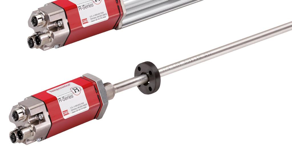
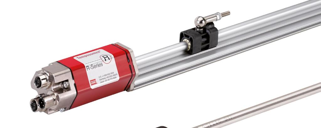
10 4. Product description and commissioning 4.1 Functionality and system design Product designation Position sensor Temposonics R-Series Sensor model Temposonics RP (profile sensor) Temposonics RH (rod sensor) Temposonics RD4 (detached sensor electronics) Temposonics RF (flexible sensor rod) Stroke length RP mm (1 200 in.) RH mm (1 300 in.) RD mm (1 200 in.) RF mm (6 787 in.) Output signal Profinet IO RT Application The Temposonics position sensors are used for measurement and conversion of the length (position) variable in the fields of automated systems and mechanical engineering. Principle of operation and system construction The absolute, linear position sensors provided by MTS Sensors rely on the company s proprietary Temposonics magnetostrictive technology, which can determine position with a high level of precision and robustness. Each Temposonics position sensor consists of a ferromagnetic waveguide, a position magnet, a strain pulse converter and supporting electronics. The magnet, connected to the object in motion in the application, generates a magnetic field at its location on the waveguide. A short current pulse is applied to the waveguide. This creates a momentary radial magnetic field and torsional strain on the waveguide. The momentary interaction of the magnetic fields releases a torsional strain pulse that propagates the length of the waveguide. When the ultrasonic wave reaches the end of the waveguide it is converted into an electrical signal. Since the speed of the ultrasonic wave in the waveguide is precisely known, the time required to receive the return signal can be converted into a linear position measurement with both high accuracy and repeatability. Position magnet (Magnetic field) Torsional strain pulse converter 2 Sensing element (Waveguide) Current pulse generates magnetic field Interaction with position magnet 1 fi eld generates torsional strain 3 pulse Torsional strain Strain pulse pulse propagates detected by 4 converter 5 Fig. 2: Time-based magnetostrictive position sensing principle Time-of-fl ight converted into position Modular mechanical and electronic construction The sensor rod or profile protects the inner sensor element. The sensor electronics housing, a rugged aluminum construction, contains the complete electronic interface with active signal conditioning. Double shielding ensures high safety of operation and optimum EMC (Electromagnetic Compatibility). The external position magnet is a permanent magnet. Mounted on the mobile machine part, it travels along the sensor rod or profile and triggers the measurement through the sensor rod wall. The sensor can be connected directly to a control system. Its electronics generates a strictly position-proportional signal output between start and end position. I 10 I
11 RP 4.2 Styles and installation of Temposonics RP M5 or #10 screw Ø 5.5 (0.21) 49 (1.93) 45 (1.77) Sensor electronics housing (5) Null zone 28 (1.1) Magnet Stroke length (1 200) Dead zone 66 / 71* (2.6 / 2.8*) 28 (1.1) 9 (0.36) 35.6 (1.4) 50 (1.97) 68 (2.68) 2 (0.08) 15.5 (0.61) Adjustable mounting clamp 14.5 (0.57) * > 5000 mm (196.9 in.) stroke length Controlling design dimensions are in millimeters and measurements in ( ) are in inches Fig. 3: Temposonics RP with U-magnet Installation of RP The position sensor can be installed in any position. Normally, the sensor is firmly installed and the position magnet is fastened to the mobile machine part. Thus it can travel along the sensor profile. The sensor is fitted on a flat machine surface using the mounting clamps (Fig. 4). A length-dependent number of these clamps are delivered with the sensor and must be distributed over the profile at regular distances. For fastening use M5 20 screws to DIN 6912 that should be tightened with a fastening torque of 5 Nm. NOTICE Take care to mount the sensor in an axially parallel position to avoid damage to magnet and sensor. Fastening torque: 5 Nm 50 (1.97) 9.5 (0.38) Bore Ø 5.5 (Ø 0.27) 14.5 (0.57) Fig. 4: Mounting clamps (part no ) with cylinder screw M5 20 Alternative: If only limited space is available, the profile sensor can be mounted also via the T-rail in the profile bottom using an T-slot nut M5 (part no ) or a sliding block (Fig. 5). M5 5 ( 0.2) Fig. 5: T-slot nut M5 (part no ) Controlling design dimensions are in millimeters and measurements in ( ) are in inches I 11 I
12 4.3 Styles and installation of Temposonics RH RH-H / -M / -S / -V 53 (2.09) 46 (1.81) 15.5 (0.61) Sensor electronics housing 130 (5.1) 10 (0.4) A/F (0.98) Null zone 51 (2.01) Magnet Stroke length (1 300) Flange»M«/»V«: M g Flange»S«/»H«: ¾"-16 UNF-3A Dead zone 63.5 / 66* (2.5 / 2.6* ) Ø 10 ±0.13 (Ø 0.39 ±0.01) * Stroke length > 5000 mm (196.9 in.) RH-D A/F 46 Dead zone 63.5 / 66* (2.5 / 2.6*) 8 (0.31) RH-T / -U Magnet Flange»D«: M g Ø 10 (Ø 0.39) Ø 12.8 ±0.1 (Ø 0.5 ±0.004) (0.12) (0.87) (0.59) * Stroke length > 5000 mm (196.9 in.) 51.3 (2.02) 9.65 (0.38) 7.11 (0.28) Null zone 51 (2.01) A/F 44.5 Stroke length (1 300) Dead zone 63.5 / 66* (2.5 / 2.6*) 44.5 (1.75) Magnet Ø 25.4 (Ø 1) Ø 10 ±0.13 (Ø 0.39 ±0.01) Flange»T«&»U«: ¾"-16 UNF-3A * Stroke length > 5000 mm (196.9 in.) RH-R A/F 46 Dead zone 70 / 72.5* (2.76 / 2.85*) M4 thread Magnet Ø 10 ±0.13 (Ø 0.39 ±0.01) Flange»R«: M g Controlling design dimensions are in millimeters and measurements in ( ) are in inches Fig. 6: Temposonics RH with ring magnet part (0.14) 6 (0.24) * Stroke length > 5000 mm (196.9 in.) I 12 I
13 R-Series RH-J A/F 46 Null zone 51 (2.01) Magnet Flange»J«: M g Stroke length (1 300) Dead zone 73.6 (2.9) 4.6 (0.18) 6.2 (0.24) Ø 12.7 ±0.13 (Ø 0.5 ±0.01) R-Series RH-B 8 49 (1.93) Sensor electronics housing 120 (4.74 ) Null zone 61 (2.4) Stroke length (1 300) Dead zone 52 / 54 / 57** (2.05 / 2.13 / 2.24) 43.7 (1.72) Magnet Ø 6.8 ±0.13 (Ø 2.68 ±0.01) Controlling design dimensions are in millimeters and measurements in ( ) are in inches ** Stroke length (1 62): 52 (2.05) dead zone Stroke length ( ): 54 (2.13) dead zone Stroke length ( ): 57 (2.24) dead zone Fig. 7: Temposonics RH with ring magnet part 2 Installation of RH with threaded flange»d«,»h«,»j«,»m«,»r«,»s«,»t«,»u«&»v«fix the sensor rod via threaded flange M g, M g or ¾"-16 UNF-3A. In the event of servicing, the sensor rod with flange remains in the cylinder Fastening torque 50 Nm Position magnet Fig. 8: Mounting example of threaded flange»d«,»h«,»j«,»m«,»r«,»s«,»t«,»u«&»v«installation of a rod-style sensor in a fluid cylinder The rod-style version has been developed for direct stroke measurement in a fluid cylinder. Mount the sensor via threaded flange or a hex nut. Mounted on the face of the piston, the position magnet travels over the rod without touching it and indicates the exact position through the rod wall independent of the hydraulic fluid. The pressure resistant sensor rod is installed into a bore in the piston rod. The base unit is mounted by means of only two screws. It is the only part that needs to be replaced if servicing is required, i.e. the hydraulic circuit remains closed. For more information see chapter "4.7 Replacement of sensor" on page 26. Fig. 9: Sensor in cylinder Base unit The sensor electronics housing with sensing element can be replaced Hydraulics sealing There are two ways to seal the flange contact surface (Fig. 10): 1. A sealing by using an O-ring (e.g mm ( in.), mm ( in.)) in a cylinder bottom groove. 2. A sealing by using an O-ring in the undercut. For threaded flange (¾"-16 UNF-3A)»H«/»S«/»T«/»U«: O-ring mm ( in.) (part no ) For threaded flange (M g)»D«/»M«/»R«/»V«: O-ring mm ( in.) (part no ) For threaded flange (M g)»J«: O-ring mm ( in.) (part no ) 8/ RH-B is for replacement (see chapter 4.7) I 13 I
14 In the case of threaded flange M g or M g, provide a screw hole based on ISO (Fig. 11). See ISO for further information. Sealing via O-ring in cylinder end cap groove Sealing via O-ring in the flange undercut Fig. 10: Possibilities of sealing Note the fastening torque of 50 Nm. Seat the flange contact surface completely on the cylinder mounting surface. The cylinder manufacturer determines the pressure-resistant gasket (copper gasket, O-ring, etc.). The position magnet should not grind on the sensor rod. The piston rod drilling (RH-H/-M/-R/-S/-T/-U/-V: rod Ø 10 mm: Ø 13 mm ( Ø 0.51 in.); RH-D: rod Ø 10 mm: Ø 16 mm ( Ø 0.63 in.); RH-J: rod Ø 12.7 mm: Ø 16 mm ( Ø 0.63 in.)) depends on the pressure and piston speed. Adhere to the information relating to operating pressure. Protect the sensor rod against wear. Notice for metric threaded flanges Thread (d 1 P) d 2 d 3 d 4 d L L 2 L 3 L 4 Z ±1 RH-M / -R / -V M g RH-D M g RH-J M g A 0.2 A Ød 5 Ød 2 L 3 A R0.4 Ra 3.2 Ra 3.2 A Ød 4 (Gauging) L 1 R0.3 R ±5 L 2 L 4 A Pitch diameter Controlling design dimensions are in millimeters Z Ød 3 (Reference) Thread (d 1 P) This dimension applies when tap drill cannot pass through entire boss. Fig. 11: Notice for metric threaded flange M g / M g based on DIN ISO I 14 I
15 4.4 Styles and installation of Temposonics RD4 Sensor electronics housing with bottom cable entry 8.2 (0.32) 7.7 (0.3) 24.7 (0.97) Ø 26.5 (Ø 1.04) 24.7 (0.97) Ø 6.2 (Ø 0.24) 25 (0.98) Ø 19 (Ø 0.75) 41 (1.61) Mounting block 45 (1.77) Sensor electronics housing 120 (4.74) 15.5 (0.61) 45 (1.77) 38 (1.5) 49 (1.93) 2 (0.08) 50 (1.97) Recommendation: Use M6 45 (ISO 4762) screws for sensor fastening. Fastening torque: 6 Nm. Sensor electronics housing with side cable entry 7.7 ( (0.97) 24.7 (0.97) 8.2 (0.32) Ø 6.2 (Ø 0.24) 41 (1.61) 49 (1.93) 45 (1.77) Ø 18 (Ø 0.71) 5 (0.2) 38 (1.5) 45 (1.77) Mounting block 45 (1.77) Sensor electronics housing 120 (4.74) Recommendation: Use M6 45 (ISO 4762) screws for sensor fastening. Fastening torque: 6 Nm (0.61) Controlling design dimensions are in millimeters and measurements in ( ) are in inches Fig. 12: Temposonics RD4 sensor electronics housings I 15 I
16 Threaded flange»c«&»d«(for bottom or side cable entry) PUR cable: Ø 6 (Ø 0.24) Bending radius: > 24 (> 0.94) Cable length (bottom cable entry): 65 / 170 / 230 / 350 (2.6 / 6.7 / 9.1 / 13.8) Cable length (side cable entry): 250 / 400 / 600 (9.8 / 15.7 / 23.6) Cable for bottom cable entry Cable for side cable entry Threaded flange»g«(for bottom or side cable entry) PUR cable: Ø 6 (Ø 0.24) Bending radius: > 24 (> 0.94) Cable length (bottom cable entry): 65 / 170 / 230 / 350 (2.6 / 6.7 / 9.1 / 13.8) Cable length (side cable entry): 250 / 400 / 600 (9.8 / 15.7 / 23.6) Cable for bottom cable entry Cable for side cable entry 26.9 (1.1) 26.9 (1.1) Threaded flange»m«&»t«(for bottom or side cable entry) PUR cable: Ø 6 (Ø 0.24) Bending radius: > 24 (> 0.94) Cable length (bottom cable entry): 65 / 170 / 230 / 350 (2.6 / 6.7 / 9.1 / 13.8) Cable length (side cable entry): 250 / 400 / 600 (9.8 / 15.7 / 23.6) Cable for bottom cable entry Cable for side cable entry Pressure fit flange»s«(for bottom or side cable entry) 26.9 (1.1) 32 (1.26) 4.5 (0.18) 32 (1.26) A/F (0.18) 32 (1.26) A/F (0.18) Null zone 51 (2.01) A/F 46 Magnet Stroke length (1 200) Dead zone 63.5 / 66* (2.5 / 2.6) Threaded flange»c«: M g Threaded flange»d«: ¾"-16 UNF-3A * Stroke length > 5000 mm (196.9 in.) Null zone 51 (2.01) 25 (0.98) 25 (0.98) Magnet Stroke length (1 200) Threaded flange»g«: M g Null zone 51 (2.01) Magnet Stroke length (1 200) Dead zone 63.5 / 66* (2.5 / 2.6*) * Stroke length > 5000 mm (196.9 in.) Threaded flange»m«: M g Threaded flange»t«: ¾"-16 UNF-3A Dead zone 63.5 / 66* (2.5 / 2.6) Ø 10 ± 0.13 (Ø 0.39 ± 0.01) Ø 10 ± 0.13 (Ø 0.39 ± 0.01) * Stroke length > 5000 mm (196.9 in.) Ø 10 ± 0.13 (Ø 0.39 ± 0.01) PUR cable: Ø 6 (Ø 0.24) Bending radius: > 24 (> 0.94) Cable length (bottom cable entry): 65 / 170 / 230 / 350 (2.6 / 6.7 / 9.1 / 13.8) Cable length (side cable entry): 250 / 400 / 600 (9.8 / 15.7 / 23.6) Cable for bottom cable entry Cable for side cable entry 26.9 f6 (1.1) Null zone (1.26) (0.84) 4.5 (0.18) 12.7 (0.5) Magnet Stroke length (1 100) Dead zone 63.5 (2.5) Ø 10 ± 0.13 (Ø 0.39 ± 0.01) Controlling design dimensions are in millimeters and measurements in ( ) are in inches Fig. 13: Temposonics RD4 flanges with ring manget I 16 I
17 NOTICE Note for installation respectively for replacement The serial numbers (S/N:) of cable and sensor electronics housing must match so that the position measurement is correct. FNr.: Serial number example Hydraulics sealing There are the following ways to seal the flange contact surface (Fig. 15): For threaded flange»c«/»d«: 1. A sealing by using an O-ring (e.g mm ( in.) mm ( in.)) in a cylinder end cap groove. For threaded flange (¾"-16 UNF-3A)»D«/»T«: 2. A sealing by using an O-ring mm ( in.) (part no ) in the undercut. For threaded flange (M g)»C«/»M«&»G«: 3. A sealing by using O-ring mm ( in.) (part no ) in the undercut. In this case a screw hole based on ISO (Fig. 16) must be provided. See ISO for further information. For threaded flange»c«/»d«for threaded flange»d«/»t«for threaded flange»c«/»m«&»g«notice Mount the sensor as follows: 1. Mount the flange with sensor rod 2. Mount the sensor electronics housing 3. Connect the cable between flange and the sensor electronics housing Sealing via O-ring e.g ( ) in cylinder end cap groove Sealing via O-ring ( ) in the flange undercut Sealing via O-ring ( ) in the flange undercut The steps mentioned above will be explained in chapter 4.4.1, chapter and chapter Installation of RD4 with threaded flange Fix the sensor rod via threaded flange M g or ¾"-16 UNF-3A. Threaded flange»c«/»d«fastening torque 50 Nm Threaded flange»m«/»t«,»g«fig. 14: Mounting example of threaded flange»c / D«,»M / T«&»G«Installation of a rod-style sensor in a fluid cylinder The rod-style version has been developed for direct stroke measurement in a fluid cylinder. Mount the sensor via threaded flange or a hex nut. Mounted on the face of the piston, the position magnet travels over the rod without touching it and indicates the exact position through the rod wall independent of the hydraulic fluid. The pressure resistant sensor rod is installed into a bore in the piston rod. Controlling design dimensions are in millimeters and measurements in ( ) are in inches I 17 I Fig. 15: Possibilities of sealing Note the fastening torque of 50 Nm. Seat the flange contact surface completely on the cylinder mounting surface. The cylinder manufacturer determines the pressure-resistant gasket (copper gasket, O-ring, etc.). The position magnet should not grind on the sensor rod. The piston rod drilling ( Ø 13 mm ( Ø 0.51 in.)) depends on the pressure and piston speed. Adhere to the information relating to operating pressure. Protect the sensor rod against wear. Notice for metric threaded flanges Thread (d 1 P) d 2 d 3 d 4 d L L 2 L 3 L 4 Z ±1 RD4-C M g RD4-G / -M M g L 3 A R0.4 R0.3 R0.1 A Ød 5 Ra 3.2 Ra 3.2 Pitch diameter Controlling design dimensions are in millimeters 0.1 A 0.2 A Z 45 ±5 L 1 Ød 3 (Reference) Thread (d 1 P) Fig. 16: Notice for metric threaded flange M g based on DIN ISO L 2 A Ød 2 Ød 4 (Gauging) L 4 This dimension applies when tap drill cannot pass through entire boss.
18 4.4.2 Installation of RD4 with pressure fit flange Cylinder mounting Install the rod using the pressure fit flange. Seal it off by means of the O-ring and the back-up ring. Block the pressure fit flange using a shoulder screw (Fig. 18). For details of the pressure fit flange»s«see Fig. 18. Also note the mounting examples in Fig. 19 and Fig (0.2) 32 (1.26) 20.3 (0.8) 2.5 (0.1) Installation of RD4's sensor electronics housing The following section explains the connection of a RD4 sensor with bottom cable entry (Fig. 19) and side cable entry (Fig. 20) based on RD4-S. The sensor electronics of RD4 sensors with threaded flange are mounted in the same way. Sensor electronics with bottom cable entry Connect the rod via the connector to the sensor electronics. Mount the sensor electronics so that you can lead the cables below the bottom of the housing. Thus the sensor system including the connection cables is fully encapsulated and protected against external disturbances (Fig. 19). Note the bending radius of the cable if you run the cable between sensor electronics and rod (see Fig. 13). 20 (0.79) Bore 27 H7 (1.07) Included in delivery: O-ring (part no ) Back-up ring (part no ) 15 Magnet For side cable entry: Ø (Ø ) bore for cable to electronics housing For bottom cably entry: Ø (Ø ) to push single wires through Fig. 17: Example of mounting detail: Shoulder screw 8-M6 (ISO 7379) with internal hexagon (0.4) 5.8 (0.23) Ø 22.9 (Ø 0.9) Fig. 18: Pressure fit flange»s«details ( ) 22.9 (0.9) 4.8 (0.2) 44.7 (1.76) 4.4 (0.17) 14.7 (0.58) Note for cylinder installation: The position magnet should not grind on the sensor rod. The piston rod drilling ( Ø 13 mm ( Ø 0.51 in.)) depends on the pressure and piston speed. Adhere to the information relating to operating pressure. Protect the sensor rod against wear. 7.1 (0.28) 12.7 (0.5) Non-magnetic material Fig. 19: Mounting example of pressure fit flange»s«and sensor electronics with bottom cable entry Sensor electronics with side cable entry Connect the rod via the cable to the sensor electronics on the side. Encapsulate the sensor system including the connection cables (Fig. 20). Note the bending radius of the cable if you run the cable between sensor electronics and rod (see Fig. 13). O-ring (part no ) Back-up ring (part no ) Magnet Non-magnetic material Fig. 20: Mounting example of pressure fit flange»s«and sensor electronics with side cable entry I 18 I Controlling design dimensions are in millimeters and measurements in ( ) are in inches
19 NOTICE To fulfill the EMC standards for emission and immunity the following points are necessary: The sensor electronics housing has to be connected to machine ground. The cable between the sensor and the electronics must be integrated into a metallic housing. Connect the flange to the sensor electronics housing via the molex connectors for bottom cable entry respectively via the 6 pin cable for side cable entry. Mounting of sensor electronics housing Mount the sensor electronics housing with 4 M6 45 (ISO 4762) screws via the mounting block. Note the fastening torque of 6 Nm. 4 M6 45 (ISO 4762) screws Fastening torque: 6 Nm Mounting block Fig. 21: Mounting of RD4 s sensor electronics housing (example of bottom cable entry) I 19 I
20 4.5 Styles and installation of Temposonics RF RF-C 49 (1.93) Sensor electronics housing 120 (4.74) 7 Null zone 61 (2.4) (0.28) Total length Stroke length ,000 (6 787) Dead zone see table 43.7 (1.72) 15.5 (0.61) Magnet 11.5 (0.45) Not flexible 107 (4.21) Ø 8 ± 0.23 (Ø 0.31 ± 0.01) Stroke length Tolerance of total length Dead zone Up to 7620 mm ( in.) +8 mm (0.31 in.) / 5 mm (0.20 in.) 94 mm (3.70 in.) Up to 10,000 mm ( in.) +15 mm (0.59 in.) / 15 mm (0.59 in.) 100 mm (3.94 in.) Up to 15,000 mm ( in.) +15 mm (0.59 in.) / 30 mm (1.18 in.) 120 mm (4.72 in.) Up to 20,000 mm ( in.) +15 mm (0.59 in.) / 45 mm (1.77 in.) 140 mm (5.51 in.) Note: Tolerance of total length has no influence on the stroke length. RF-M / -S 53 (2.09) 46 (1.81) 15.5 (0.61) Sensor electronics housing 130 (5.1) Controlling design dimensions are in millimeters and measurements in ( ) are in inches Null zone 51 (2.01) A/F 46 Magnet 25 (0.98) Not flexible 97 (3.82) Total length Stroke length ,000 (6 787) Flange»M«: M g Flange»S«: ¾"-16UNF-3A Dead zone see table Ø 8 ± 0.23 (Ø 0.31 ± 0.01) Stroke length Tolerance of total length Dead zone Up to 7620 mm ( in.) +8 mm (0.31 in.) / 5 mm (0.20 in.) 94 mm (3.70 in.) Up to 10,000 mm ( in.) +15 mm (0.59 in.) / 15 mm (0.59 in.) 100 mm (3.94 in.) Up to 15,000 mm ( in.) +15 mm (0.59 in.) / 30 mm (1.18 in.) 120 mm (4.72 in.) Up to 20,000 mm ( in.) +15 mm (0.59 in.) / 45 mm (1.77 in.) 140 mm (5.51 in.) Note: Tolerance of total length has no influence on the stroke length. Fig. 22: Temposonics RF base unit with ring magnet (top) and RF with threaded flange with ring magnet (bottom) Note the following information when mounting a RF sensor: 1. Always insert the flexible sensor rod in a support tube (e.g. pressure rod HD / HL / HP or HFP profile). The support tube with an inside diameter of 9.4 mm (0.37 in.) consists of non-magnetic material. The support tube can be straight or bent (note the bending radius in Fig. 24). 2. Do never bend beyond the minimum bending radius of 250 mm (9.84 in.). 3. Note the minimum distance to a spatial limitation of 300 mm (11.81 in.), when mounting / dismounting the sensor (Fig. 24). 4. Note that the first 107 mm (4.21 in.) (for RF-C) respectively 97 mm (3.82 in.) (for RF-M) of the sensor rod are not flexible. Position magnet Fig. 23: Sensor with support tube Non-magnetic support tube, inner-ø 9.4 (0.37) I 20 I Controlling design dimensions are in millimeters and measurements in ( ) are in inches
21 NOTICE Smaller radiuses cause damage to the flexible sensor rod. Socket head screw M (20) recommended 300 ( 11.81) Magnet R > 250 (R > 9.84) 10 (0.4) A/F 46 Customized support tube required, e.g. Ø (Ø ), inside Ø 9.4 (Ø 0.37), non-magnetic Fastening torque of socket head screw M4 90: 2 Nm Fig. 25: Mounting with socket head screws M4 90 Flange M g ¾" 16 UNF-3A NOTICE Connect the sensor electronics housing to machine ground to fulfill the EMC standards for emission and immunity. Fig. 24: Clearances for installation Installation of RF with threaded flange»m«,»s«or RF with pressure rod HD / HL / HP Fix the sensor rod via threaded flange M g or ¾"-16 UNF-3A. This is the way you mount the RF sensors: Fastening torque 50 Nm Sensor design RF-C RF-C with pressure rod HD / HL / HP or HFP profile (see accessories) RF-M / RF-S Mounting Insert the flexible sensor rod in a support tube. Mount the sensor electronics housing by means of two non-magnetic socket head screws M4 90. Fastening torque: 2 Nm (see Fig. 25) Recommendation: Seal the sensor via flange. Advantage: The flexible sensor rod is inserted in a support tube. Mount the sensor electronics housing by means of two non-magnetic socket head screws M4 90. Fastening torque: 2 Nm (see Fig. 25) Insert the flexible sensor rod in a support tube. Mount the sensor via flange. Fig. 26: Mounting example of threaded flange»m«/»s«or pressure rod HD / HL / HP Installation of a RF sensor with pressure rod HD / HL / HP in a fluid cylinder: The rod-style version has been developed for direct stroke measurement in a fluid cylinder. Mount the sensor via threaded flange or a hex nut. Mounted on the face of the piston, the position magnet travels over the rod without touching it and indicates the exact position through the rod wall independent of the hydraulic fluid. The pressure resistant sensor rod is installed into a bore in the piston rod. The base unit is mounted by means of only two screws. It is the only part that needs to be replaced if servicing is required, i.e. the hydraulic circuit remains closed. For more information see chapter "4.7 Replacement of sensor" on page 26. I 21 I
22 Hydraulics sealing when using a RF sensor in a pressure rod HD / HL / HP There are two ways to seal the flange contact surface (Fig. 27): 1. A sealing by using an O-ring (e.g mm ( in.), mm ( in.)) in a cylinder end cap groove. 2. A sealing by unsing an O-ring in the undercut. For threaded flange (¾"-16 UNF-3A)»S«: O-ring mm ( in.) (part no ) For threaded flange (M g)»M«: O-ring mm ( in.) (part no ) In this case, a screw hole based on ISO (Fig. 28) must be provided. See ISO for further information. Notice for metric threaded flanges Thread (d 1 P) d 2 d 3 d 4 d L L 2 L 3 L 4 Z ±1 RF-M / optional pressure rod HD M g L 3 A R0.4 R0.3 R A 0.2 A Ød 5 45 ±5 Ra 3.2 Ra 3.2 L 1 L 2 A Ød 2 Ød 4 (Gauging) L 4 Z Ød 3 (Reference) Thread (d 1 P) Sealing via O-ring in cylinder end cap groove Fig. 27: Possibilities of sealing Sealing via O-ring in the flange undercut A This dimension applies when Pitch diameter tap drill cannot pass through Controlling design dimensions are in millimeters entire boss. Fig. 28: Notice for metric threaded flange M g based on DIN ISO For additional information about optional accessories see: HFP Profile (document part number: ) Pressure rod HD / HL / HP (document part number: ) Note the following points when using a RF-M / -S sensor or RF-C with pressure rod HD / HL / HP: Note the fastening torque of 50 Nm. Seat the flange contact surface completely on the cylinder mounting surface. The cylinder manufacturer determines the pressure-resistant gasket (copper gasket, O-ring, etc.). The position magnet should not grind on the sensor rod. The piston rod drilling for RF sensors with pressure rod (rod Ø 12.7 mm (0.5 in.)) is 16 mm ( 0.63 in.). The borehole depends on the pressure and piston speed. Adhere to the information relating to operating pressure. Protect the sensor rod against wear. I 22 I
23 4.6 Magnet installation Magnet Typical sensors Benefits Ring magnets Rod models Rotationally symmetrical (RH, RD4, RF) magnetic field U-magnets Block magnets Magnet sliders Profile & rod models (RP, RH, RD4, RF) Profile & rod models (RP, RH, RF) Profile models (RP) Height tolerances can be compensated The magnet can be lifted off Height tolerances can be compensated The magnet is guided through the profile The distance between the magnet and the waveguide is strictly defined Easy coupling via the ball joint 8 ±2 (0.31 ±0.08) Concentric mounting of block magnet 1 Block magnet 2 Non-magnetic mounting plate Air gap: 3 ±2 (0.12 ±0.08) Fig. 31: Mounting of block magnet (part no ) Sensor element Magnet mounting with magnetic material When using magnetic material the dimensions of Fig. 32 must be observed. A. If the position magnet aligns with the drilled piston rod B. If the position magnet is set further into the drilled piston rod, install another non-magnetic spacer (e.g. part no ) above the magnet. A B M4 2 1 Fig. 29: Typical use of magnets Mounting ring magnets, U-magnets & block magnets Install the magnet using non-magnetic material for mounting device, screws, spacers etc.. The magnet must not grind on the sensor rod. Alignment errors are compensated via the air gap. Permissible surface pressure: Max. 40 N/mm 2 (only for ring magnets and U-magnets) Fastening torque for M4 screws: 1 Nm; use washers, if necessary Minimum distance between position magnet and any magnetic material has to be 15 mm (0.6 in.) (Fig. 32). If no other option exists and magnetic material is used, observe the specified dimensions (Fig. 32). NOTICE Mount ring magnets and U-magnets concentrically. Mount block magnets centrically over the sensor rod or the sensor profile. Do not exceed the maximum acceptable gap (Fig. 30 / Fig. 31). Concentric mounting of U-magnet Air gap Part no : 1.75 ±1 (0.07 ±0.04) Part no : 3 ±1 (0.12 ±0.04) 1 U-magnet 2 Non-magnetic mounting plate and fasteners Fig. 30: Mounting of U-magnet (part no or part no ) 2 M4 1 Magnet Fig. 32: Installation with magnetic material Magnetic material Sensors with stroke lengths 1 meter (3.3 ft.) Support horizontally installed sensors with a stroke length from 1 meter (3.3 ft.) mechanically at the rod end. Without the use of a support, rod and position magnet may be damaged. A false measurement result is also possible. Longer rods require evenly distributed mechanical support over the entire length (e.g. part no ). Use an U-magnet (Fig. 33) for measurement. U-magnet 3 Sensor rod Non-magnetic fixing clip Magnet 1 Null zone, depends on sensor model (see Fig. 35 / 36 / 37) 2 Distance between position magnet and any magnetic material ( 15 mm ( 0.6 in.)) 3 Non-magnetic spacer ( 5 mm ( 0.2 in.)) Recommendation: 8 mm (0.31 in.) Fig. 33: Example of sensor support (part no ) Controlling design dimensions are in millimeters and measurements in ( ) are in inches I 23 I
24 Start- and end positions of the position magnets Consider the start and end positions of the position magnets during the installation. To ensure that the entire stroke length is electrically RP with U-magnet Sensor electronics housing Reference edge of mounting Start position 28 (1.1) End position 66 / 71* (2.6 / 2.8*) usable, the position magnet must be mechanically mounted as follows. RH with block magnet Sensor electronics housing Reference edge of mounting Start position 48.5 (1.91) End position 66 / 68.5* (2.6 / 2.7*) * Stroke length > 5000 mm (196.9 in.) RP with magnet slider S, N, V, G Sensor electronics housing Reference edge of mounting Start position 12 (0.47) End position 82 / 87* (3.23 / 3.43*) * Stroke length > 5000 mm (196.9 in.) RD4-M / -T / -G with ring magnet & U-magnet Reference edge of mounting Start position 51 (2.01) End position 63.5 / 66* (2.5 / 2.6*) RP with block magnet * Stroke length > 5000 mm (196.9 in.) Sensor electronics housing Reference edge of mounting Start position 25.5 (1) End position 68.5 / 73.5* (2.7 / 2.9*) * Stroke length > 5000 mm (196.9 in.) RD4-C / -D with ring magnet & U-magnet Reference edge of mounting Start position 51 (2.01) End position 63,5 / 66* * Stroke length > 5000 mm (196.9 in.) * Stroke length > 5000 mm (196.9 in.) RH with ring magnet & U-magnet Sensor electronics housing Reference edge of mounting Start position 51 (2.01) End position 63.5 / 66* (2.5 / 2.6*) RD4-S with ring magnet & U-magnet Reference edge of mounting Start position 21.4 (0.84) End position 63.5 (2.5) * Stroke length > 5000 mm (196.9 in.) Fig. 34: Start- & end positions of magnets, part 1 Fig. 35: Start- & end positions of magnets, part 2 I 24 I Controlling design dimensions are in millimeters and measurements in ( ) are in inches
25 R-Series RF-M / -S with ring magnet & U-magnet Sensor electronics housing Reference edge of mounting Start position 51 (2.01) End position See table Multi-position measurement The minimum distance between the magnets is 75 mm (3 in.). Profile models with U-magnets 75 ( 3) R-Series RF-M / -S with block magnet Sensor electronics housing Reference edge of mounting Start position 48.5 (1.91) End position See table Profile models with magnet sliders 75 ( 3) Profile models with block magnets R-Series RF-C with ring magnet & U-magnet Sensor electronics housing Reference edge of mounting Start position 61 (2.4) End position See table 75 ( 3) Rod models with ring magnets & U-magnets 75 ( 3) R-Series RF-C with block magnet Sensor electronics housing Reference edge of mounting Start position 58.5 (2.3) End position See table Rod models with block magnets 75 ( 3) Stroke length RF Up to 7620 mm (300 in.) Up to 10,000 mm ( in.) Up to 15,000 mm ( in.) Tolerance of total length +8 mm (0.31 in.) / 5 mm (0.20 in.) +15 mm (0.59 in.) / 15 mm (0.59 in.) +15 mm (0.59 in.) / 30 mm (1.18 in.) End position of ring magnet / U-magnet 94 mm (3.70 in.) 100 mm (3.94 in.) 120 mm (4.72 in.) End position of block magnet 96.5 mm (3.8 in.) mm (4.04 in.) mm (4.82 in.) Fig. 37: Minimum distance for multi-position measurement NOTICE Use magnets of the same type (e.g. 2 ring magnets ) for multi-position measurement. Do not go below a minimal distance of 75 mm (3 in.) between the magnets for multi-position measurement.* Up to 20,000 mm (787 in.) +15 mm (0.59 in.) / 45 mm (1.77 in.) 140 mm (5.51 in.) mm (5.61 in.) Fig. 36: Start- and end positions of magnets (Part 3) NOTICE On all sensors, the areas left and right of the active stroke length are provided for null and dead zone. These zones should not be used for measurement, but the active stroke length can be exceeded. I 25 I */ Contact MTS Sensors if you need a magnet distance, which is smaller than 75 mm (3 in.). Controlling design dimensions are in millimeters and measurements in ( ) are in inches
26 4.7 Replacement of sensor The base unit of the sensor models RH (RH-B) and RF (RF-C) is replaceable as shown in Fig. 38 and Fig. 39. The sensor can be replaced without interrupting the hydraulic circuit. 3. Insert the new base unit. Mount the ground lug on a screw. Tighten the screws. Base unit Note: The base unit will be delivered without ground lug. Mount the ground lug at the base unit. Ground the sensor via the ground lug. Plastic tube with inner sensor element Fastening torque 1.3 Nm Fig. 39: Replacement of the base unit (e.g. RH sensor), part 2 1. Loosen the screws. Sensor electronics housing NOTICE If necessary, the sensor electronics of sensor model RD4 can be replaced. Contact MTS Sensors for further information. Secure the base unit screws, e.g. using Loctite 243, before re-installing. 2 socket head screw M4 (A/F 2.5) 2. Pull out the base unit. Fig. 38: Replacement of the base unit (e.g. RH sensor), part 1 I 26 I
27 4.8 Electrical connections Placement of installation and cabling have decisive influence on the sensor s electromagnetic compatibility (EMC). Hence correct installation of this active electronic system and the EMC of the entire system must be ensured by using suitable metal connectors, shielded cables and grounding. Overvoltages or faulty connections can damage its electronics despite protection against wrong polarity. Connector wiring Connect the sensor directly to the control system, indicator or other evaluating systems as follows: Bus NOTICE 1. Do not mount the sensors in the area of strong magnetic or electric noise fields. 2. Never connect / disconnect the sensor when voltage is applied. Instructions for connection Use low-resistant twisted pair and shielded cables. Connect the shield to ground externally via the controller equipment. Keep control and signal leads separate from power cables and sufficiently far away from motor cables, frequency inverters, valve lines, relays, etc.. Use only connectors with metal housing and connect the shielding to the connector housing. Keep the connection surface at both shielding ends as large as possible. Connect the cable clamps to function as a ground. Keep all non-shielded leads as short as possible. Keep the earth connection as short as possible with a large cross section. Avoid ground loops. With potential differences between machine and electronics earth connections, no compensating currents are allowed to flow across the cable shielding. Recommendation: Install potential compensating leads with large cross section, or use cables with separate double shielding, and connect only one end of the shield. Use only stabilized power supplies in compliance with the specified connecting values. Grounding of profile and rod sensors Connect the sensor electronics housing to machine ground. Ground sensor types RP, RH, RD4 and RF via ground lug as shown in Fig. 40. In addition you can ground the sensor type RH via thread. Bus Fig. 41: Location of connections D58 Signal M12 female connector (D-coded) View on sensor M12 female connector (D-coded) View on sensor Power supply Pin Function 1 Tx (+) 2 Rx (+) 3 Tx ( ) 4 Rx ( ) 5 Not connected Pin Function 1 Tx (+) 2 Rx (+) 3 Tx ( ) 4 Rx ( ) 5 Not connected M12 male connector Pin Function Operating voltage VDC ( 15 / +20 %) Do not connect* 4 3 DC Ground (0 V) View on sensor 4 Do not connect* * As a connection to this pin may influence the correct startup of sensor Fig. 42: Connector wiring D58 Fig. 40: Grounding via ground lug (e.g. profile sensor) I 27 I
28 20.5 (0.81) 1.5 (0.06) 14.9 (0.59) Temposonics R-Series Profinet IO RT 4.9 Frequently ordered accessories Additional options available in our Accessories Guide Position magnets 20 (0.79) 25.3 (1) 43 (1.69) 40 (1.58) M5 14 (0.55) (1) 57 (2.24) (1.93) (0.55) M5 40 (1.58) 18 Ø 32.8 (Ø 1.29) Ø 4.3 (Ø 0.17) Ø 23.8 (Ø 0.94) Ø 13.5 (Ø 0.53) (0.12) 7.9 (0.31) Ø 32.8 (Ø 1.29) Ø 23.8 (Ø 0.94) Ø 13.5 (Ø 0.53) Ø 4.3 (Ø 0.17) 7.9 (0.31) Magnet slider S, joint at top Part no Magnet slider V, joint at front Part no U-magnet OD33 Part no Ring magnet OD33 Part no For: RP For: RP For: RP, RH, RD4 For: RH, RD4, RF Material: GFK, magnet hard ferrite Weight: Approx. 35 g Operating temperature: C ( F) Position magnets Material: GFK, magnet hard ferrite Weight: Approx. 35 g Operating temperature: C ( F) Material: PA ferrite GF20 Weight: Approx. 11 g Surface pressure: Max. 40 N/mm 2 Fastening torque for M4 screws: 1 Nm Operating temperature: C ( F) Material: PA ferrite GF20 Weight: Approx. 14 g Surface pressure: Max. 40 N/mm 2 Fastening torque for M4 screws: 1 Nm Operating temperature: C ( F) Ø 25.4 (Ø 1) Ø 13.5 (Ø 0.53) 7.9 (0.31) Ø 30.5 (Ø 1.2) Ø 19.8 (Ø 0.78) 7.6 (0.3) Ø 4.3 (Ø 0.17) 33 (1.3) 19.5 (0.77) 14 (0.55) 8 ± 2 (0.31 ± 0.08) Distance to sensor element Ø 63.5 (Ø 2.5) Ø 42 (Ø 1.65) Ø 16 (Ø 0.63) 97 Ø 4.5 (Ø 0.18) (0.37) Ring magnet OD25.4 Part no Ring magnet Part no Block magnet L Part no U-magnet OD63.5 Part no For: RH, RD4 For: RH, RD4, RF For: RP, RH, RD4 For: RH, RD4, RF Material: PA ferrite Weight: Approx. 10 g Surface pressure: Max. 40 N/mm 2 Operating temperature: C ( F) Material: PA ferrite coated Weight: Approx. 13 g Surface pressure: 20 N/mm 2 Operating temperature: C ( F) Material: Hard ferrite Weight: Approx. 20 g Fastening torque for M4 screws: 1 Nm Operating temperature: C ( F) Material: PA 66-GF30, Magnets compound-filled Weight: Approx. 26 g Surface pressure: 20 N/mm 2 Fastening torque for M4 screws: 1 Nm Operating temperature: C ( F) Magnet spacer Sealings Ø 31.8 (Ø 1.25) Ø 23.8 (Ø 0.94) Ø 14.3 (Ø 0.56) Ø 4.3 (Ø 0.17) 3.2 (0.13) Ø 15.3 (Ø 0.6) Ø 2.2 (Ø 0.09) Ø 16.4 (Ø 0.65) Ø 2.2 (Ø 0.09) Ø 19.3 (Ø 0.76) Ø 2.2 (Ø 0.09) Magnet spacer Part no O-ring for flange M g Part no O-ring for flange ¾"-16 UNF-3A Part no O-ring for flange M g Part no For: RH, RD4 For: RH, RD4, RF For: RH, RD4, RF For: RH Material: Aluminum Weight: Approx. 5 g Surface pressure: 20 N/mm 2 Fastening torque for M4 screws: 1 Nm Material: Fluoroelastomer 75 ± 5 durometer Operating temperature: C ( F) Material: Fluoroelastomer 75 ± 5 durometer Operating temperature: C ( F) Material: FPM 75 durometer Operating temperature: C ( F) I 28 I Controlling design dimensions are in millimeters and measurements in ( ) are in inches
, straight Part no. 370 677 M12 D-coded male connector (4 pin), straight Part no.")
 Cable Ø: 4 8 mm (0.16 0.")
29 Sealing Cable connectors 9 Ø 21.9 (Ø 0.86) Ø 2.6 (Ø 0.1) Ø 27 (Ø 1.06) 2.2 (0.09) 1.4 (0.05) Ø 20 (Ø 0.79) ~53 (~ 2.09) Ø 19.5 (Ø 0.77) M12 52 (2.05) O-ring for pressure fit flange Part no Back-up ring for pressure fit flange Part no M12 A-coded female connector (5 pin), straight Part no M12 D-coded male connector (4 pin), straight Part no For: RD4 For: RD4 Material: GD-Zn, Ni Material: Nitrile rubber Operating temperature: C ( F) Accessory for M12 cable connector Cables Application: Pressure fit flange Material: Polymyte 90 durometer Material: Zinc nickel-plated Termination: Screw Termination: Insulation-displacement Contact insert: CuZn Cable Ø: mm ( in.) Cable Ø: 4 8 mm ( in.) Operating temperature: Wire: 1.5 mm² C ( F) Operating temperature: Ingress protection: IP65 / IP C ( F) (correctly fitted) Ingress protection: IP67 (correctly fitted) Fastening torque: 0.6 Nm Fastening torque: 0.6 Nm M12 Ø 16 (Ø 0.63) 16 (0.63) 6 (0.24) M12 connector end cap Part no Cable with M12 D-coded male connector M12 D-coded, male connector, 5 m (16.4 ft.) Part no Cable with M12 D-coded male connector RJ45 male connector, 5 m (16.4 ft.) Part no PUR cable Part no Female connectors M12 should be Material: PUR jacket; green covered by this protective cap Features: Cat 5e Material: Brass nickel-plated Cable length: 5 m (16.4 ft) Ingress protection: IP67 (correctly fitted) Cable Ø: 6.5 mm (0.26 in.) Fastening torque: Nm Ingress protection: IP65, IP67, IP68 (correctly fitted) Operating temperature: C ( F) Mounting hardware Material: PUR jacket; green Features: Cat 5e Cable length: 5 m (16.4 ft) Cable Ø: 6.5 mm (0.26 in.) Ingress protection M12 connector: IP67 (correctly fitted) Ingress protection RJ45 connector: IP20 (correctly fitted) Operating temperature: C ( F) Material: PUR jacket; green Features: Cat 5 Cable Ø: 6.5 mm (0.26 in.) Dimensions: mm 2 (22/7 AWG) Operating temperature: C ( F) A/F 27 M g 8.7 (0.34) A/F 28 ¾"-16 UNF-3A 11 (0.43) 4 Holes Ø 5.3 (Ø 0.21) 28 (1.1) 9 (0.35) 2 (0.08) 50 (1.97) 68 (2.68) Mounting clamp width: 14.6 (0.57) 9 (0.35) 4 (0.16) 8 (0.31) M5 thread 4.5 (1.8) 11.5 (0.45) Hex jam nut M g Part no Hex jam nut ¾"-16 UNF-3A Part no Mounting clamp Part no T-slot nut Part no For: RH, RD4, RF For: RH, RD4, RF For: RP For: RP Material: Steel, zinc, plated Material: Zinc plated with nylon insert Material: Stainless steel (AISI 304) Fastening torque for M5 screw: 4.5 Nm 9/ Follow the manufacturer s mounting instructions Controlling design dimensions are in millimeters and measurements in ( ) are in inches I 29 I
 and O-ring HD [length mm: XXXX] M HD [length in.: XXX.X] U Pressure rod with flange ¾\"-16 UNF-3A (flat-faced flange) and O-ring HL [length mm: XXXX] M HL [length in.: XXX.X] U Pressure rod with flange ¾\"-16 UNF-3A (raised-faced flange) and O-ring HP [length mm: XXXX] M HP [length in.")
![: XXX.X] U For: RH, RD4 For: RF-C For: RF-C For: RF-C Application: Used to secure sensor rods (Ø 10 mm (Ø 0.39 in.)) when using an U-magnet Material: Brass, non-magnetic Pressure rod Ø: 12.7 mm (0.](/docs-images/79/80147461/images/30-1.jpg "5 in.) Length: 255 7500 mm (10 295 in.) Operating pressure: 350 bar (5076 psi) Material flange: Stainless steel 1.4305 (AISI 303) Material rod: Stainless steel 1.")
30 Mounting hardware Pressure rods (RF) 60 (2.36) 16 (0.63) 12 (0.47) 20 (0.79) Ø 3.2 (Ø 0.13) M3 fastening screws (6 ) 3.2 (0.13) Fixing clip Part no Pressure rod with flange M g (flat-faced flange) and O-ring HD [length mm: XXXX] M HD [length in.: XXX.X] U Pressure rod with flange ¾"-16 UNF-3A (flat-faced flange) and O-ring HL [length mm: XXXX] M HL [length in.: XXX.X] U Pressure rod with flange ¾"-16 UNF-3A (raised-faced flange) and O-ring HP [length mm: XXXX] M HP [length in.: XXX.X] U For: RH, RD4 For: RF-C For: RF-C For: RF-C Application: Used to secure sensor rods (Ø 10 mm (Ø 0.39 in.)) when using an U-magnet Material: Brass, non-magnetic Pressure rod Ø: 12.7 mm (0.5 in.) Length: mm ( in.) Operating pressure: 350 bar (5076 psi) Material flange: Stainless steel (AISI 303) Material rod: Stainless steel (AISI 304) See technical bulletin RF pressure housing pipe (document part no.: ) for further information Pressure rod Ø: 12.7 mm (0.5 in.) Length: mm ( in.) Operating pressure: 350 bar (5076 psi) Material flange: Stainless steel (AISI 303) Material rod: Stainless steel (AISI 304) See technical bulletin RF pressure housing pipe (document part no.: ) for further information Pressure rod Ø: 12.7 mm (0.5 in.) Length: mm ( in.) Operating pressure: 350 bar (5076 psi) Material flange: Stainless steel (AISI 303) Material rod: Stainless steel (AISI 304) See technical bulletin RF pressure housing pipe (document part no.: ) for further information Flanges (RF) Profile (RF) Flange M g Part no Flange ¾"-16 UNF-3A Part no Profile with flange HFP [length mm: XXXXX] M HFP [length in.: XXXX.X] U For: RF-C For: RF-C For: RF-C Material: Stainless steel (AISI 303) Material: Stainless steel (AISI 303) Length: Max mm (max. 787 in.) Ingress protection: IP30 Material: Aluminum See Product Flash RF Profile (Document Part No.: ) for further information Manuals & Software available at: Controlling design dimensions are in millimeters and measurements in ( ) are in inches I 30 I
 LEDs in the sensor electronics housing lid provide information on the current sensor condition. Fig.")
31 5. Operation 5.1 Getting started The sensor is factory-set to its order sizes and adjusted, i.e. the required output signal corresponds exactly to the selected stroke length. Example: Output Profinet IO RT = % stroke length Diagnostic display (Red / green) LEDs in the sensor electronics housing lid provide information on the current sensor condition. Fig. 43: LED display Profinet LED status Status LED Green Red Information ON OFF Normal function ON ON No connection to master ON Flashing Parameterization failed OFF ON Warning! (illegal supply voltage / wrong quantity of magnets) NOTICE Observe during commissioning 1. Before initial switch-on, check carefully if the sensor has been connected correctly. 2. Position the magnet in the measuring range of the sensor during first commissioning and after replacement of the magnet. 3. Ensure that the sensor control system cannot react in an uncontrolled way when switching on. 4. Ensure that the sensor is ready and in operation mode after switching on. The bus status LED lights permanently green. 5. Check the preset span start and end values of the measuring range (see chapter 4.6) and correct them via the customer s control system, if necessary. Following network protocols are supported: RTC (Class1) (Real Time Cyclic Protocol): Protocol for cyclic IO data (process data and measured values) RTA (Real Time Acyclic Protocol): Protocol for acyclic real time data (e.g. alarms) DCP (Discover and Basic Configuration Protocol): Assignment of IP configuration and device name DCE/RPC (Distributed Computing Environment Remote Procedure Call ): Remote Procedure Calls via IP (e.g. parameter configuration) LLDP (Link Layer Discovery Protocol): Protocol used for neighborhood detection SNMP (Simple Network Management Protocol): Protocol used for network node diagnosis MRP (Media Redundancy Protocol): Searches for alternative routes in case of cable error or node error 6. Programming and configuration Software configuration These instructions describe the installation and configuration of a MTS Profinet IO RT sensor using a CP1616 Profinet IRT controller and a Siemens projecting tool (SIMATIC NCM Manager, version 5.5). For communication with the Profinet network, an ethernet connection with corresponding configuration must be selected. 1. Select Options Set PG/PC Interface (Fig. 44): Installing the software and the network card Depending on control system type. The following figures are taken from the Siemens SIMATIC NC Manager documentation. 6.1 Configuration of the network interface Step 1: Configuration of the network interface Step 2: Configuration of the sensor designation Step 3: Controller setting and preparation of the network Step 4: Integration of GSDML files (of the sensor) Step 5: Integration and configuration of the sensors a) with U402 profile (MTS profile) b) with U401 profile (encoder profile 4.1) Fig. 44: Set PG/PC Interface (source: Siemens) I 31 I
 (source: Siemens) 2. Select a sensor from the list to which a name must be assigned.")
 Note that the selected interface is configured in the same IP subnet as the CP1616 unit and that the following")

 b) with U401 profile (encoder profile 4.1) Fig. 48: List of available Profinet IO devices (source: Siemens) 3.")
: PLC Edit Ethernet Node Browse (Fig. 47) Fig.")
32 2. Select a connection from the list, which is connected with CP1616, and click OK to confirm (Fig. 45). Fig. 47: Select the MTS R-Series Profinet sensor (step 2) (source: Siemens) 2. Select a sensor from the list to which a name must be assigned. A sensor is identified by the type designation MTS-R-SERIES- PROFINET and a MAC address prefix CA. Click OK to confirm your selection (Fig. 48). Fig. 45: Set PG/PC Interface (source: Siemens) Note that the selected interface is configured in the same IP subnet as the CP1616 unit and that the following protocols are activated: QoS package planner, Profinet IO RT protocol V2.0, network monitor drivers, Internet protocol (TCP/IPv4). 6.2 Configuration of the sensor designation Step 1: Configuration of the network interface Step 2: Configuration of the sensor designation Step 3: Controller setting and preparation of the network Step 4: Integration of GSDML files (of the sensor) Step 5: Integration and configuration of the sensors a) with U402 profile (MTS profile) b) with U401 profile (encoder profile 4.1) Fig. 48: List of available Profinet IO devices (source: Siemens) 3. Assign a device name and confirm your entry with Assign name (Fig. 49). For clear sensor identification in the network, a sensor designation must be assigned. This is done in the NCM Manager. 1. Select the MTS R-Series Profinet IO RT sensor as described below (Fig. 46): PLC Edit Ethernet Node Browse (Fig. 47) Fig. 49: Select the MTS R-Series Profinet sensor (step 3) (source: Siemens) Fig. 46: Select the MTS R-Series Profinet sensor (step 1) (source: Siemens) I 32 I
 Step")

.")
 Fig.")
. Fig.")

33 6.3 Controller setting and preparation of the network Step 1: Configuration of the network interface Step 2: Configuration of the sensor designation Step 3: Controller setting and preparation of the network Step 4: Integration of GSDML files (of the sensor) Step 5: Integration and configuration of the sensors a) with U402 profile (MTS profile) b) with U401 profile (encoder profile 4.1) 3. Add a controller to the project. For this, proceed as described below (Fig. 53): Right-click project (MTS_Profinet_Example) Insert new object Select the SIMATIC PC Station 1. Start the SIMATIC NCM Manager to configure the Profinet IO RT network. 2. Create a new project under File New (Fig. 50). Subsequently, select the Name and the Path of the project file (Fig. 51). Fig. 53: Add a controller to the project (source: Siemens) Fig. 50: Create a new project (source: Siemens) The SIMATIC PC station (controller) is displayed in the right area of the project overview. Double-click the SIMATIC PC station to display the controller in the left area of the project overview (Fig. 54). Fig. 54: Controller link to project (source: Siemens) 4. Double-click Configuration with the Station selected to open the window Module HW Config to determine the network and sensor configuration (Fig. 55). Fig. 51: Assign a project name and a memory location (source: Siemens) Click OK to confirm your entry. After creating the project, the project overview opens, which will be filled with components when proceeding (Fig. 52). Fig. 55: Module HW Config (source: Siemens) Fig. 52: Project overview (source: Siemens) I 33 I
 CP Industrial Ethernet (Fig. 57) CP1616 (Fig.")
.")
. Window Properties New subnet opens (Fig. 59).")
 7.")
 (source: Siemens) Fig.")
34 5. Right-click to insert the network controller, as described below: Insert Object (Fig. 56) CP Industrial Ethernet (Fig. 57) CP1616 (Fig. 58) Select the appropriate firmware version of your CP1616. The dialog box Properties Ethernet interface opens (Fig. 58). Set the IP address of your CP To create a subnet, click button New (Fig. 58). Window Properties New subnet opens (Fig. 59). Define a name and click OK to confirm your entry. Fig. 59: Create a subnet (source: Siemens) 7. A network without sensors has been configured (Fig. 60). Fig. 56: Insert controller into the network (step 1) (source: Siemens) Fig. 60: Configuration of network without sensors (source: Siemens) Fig. 57: Insert controller into the network (step 2) (source: Siemens) Fig. 58: Set IP adress of CP1616 (source: Siemens) I 34 I

 To operate the sensor in a network, the sensor data is loaded from the GSDML file into the controller.")
. 1. For this purpose, select the following options in window HW Config (Fig.")
35 6.4 Integration of GSDML files (of the sensor) 6.5 Integration and configuration of the sensors with MTS profile Step 1: Configuration of the network interface Step 2: Configuration of the sensor designation Step 3: Controller setting and preparation of the network Step 4: Integration of GSDML files (of the sensor) Step 5: Integration and configuration of the sensors a) with U402 profile (MTS profile) b) with U401 profile (encoder profile 4.1) To operate the sensor in a network, the sensor data is loaded from the GSDML file into the controller. Step 1: Configuration of the network interface Step 2: Configuration of the sensor designation Step 3: Controller setting and preparation of the network Step 4: Integration of GSDML files (of the sensor) Step 5: Integration and configuration of the sensors a) with U402 profile (MTS profile) b) with U401 profile (encoder profile 4.1) 1. Select the MTS communication protocol from the directory displayed on the right (Fig. 62). 1. For this purpose, select the following options in window HW Config (Fig. 61): Options Install GSD file Fig. 62: Select MTS communication protocol (source: Siemens) 2. Select for U402 profile the file "MTS R-Series firmware version 1.0". Drag and drop this file from the directory into the network (dashed line). The sensor has been added to the network (Fig. 63). Fig. 61: HW Config (source: Siemens) NOTICE The U profile (encoder Profile 4.1) fulfills the requirements and functionality according to the encoder profile V4.1 (PNO no. 3162). The U profile (MTS profile) is a system developed by MTS Sensors for capturing position or velocity of up to 19 magnets. U401 and U402 are output choices of the order code. 2. Window "Install GSD File" is opened. Click button "Browse" to select one of the following GSD files (available at U402 profile (MTS profile) (GSDML) U401 profile (Encoder profile 4.1) (GSDML) Fig. 63: Add sensor to the network (source: Siemens) 10/ Depending on the integrated profile I 35 I
. Fig. 64: HW Config-Window (Source: Siemens) Select tab Parameters to realize the following sensor settings (Fig. 65): Fig.")
 Number of averages: Specifies the number of values to form an average value.")
36 3. Double-click on the MTS R-Series icon to select the sensor and enter the previously defined name into field Device name. Press OK to confirm your entries. 4. Double-click Slot 0 to open a configuration dialog box (Fig. 64). Fig. 64: HW Config-Window (Source: Siemens) Select tab Parameters to realize the following sensor settings (Fig. 65): Fig. 65: Properties MTS-R-Series (Source: Siemens) a) Resolution: Specifies the resolution for position measurement. Possible values: 1, 2, 5, 10, 50, 100 μm b) Number of averages: Specifies the number of values to form an average value. Possible values: 1, 2, 4, 8 c) Velocity window: Specifies number of position values for determining the speed of the position magnet. Possible values: 2, 4, 8, 16 d) Velocity unit: Specifies the unit of velocity output. Possible values: steps/s, steps/100ms, steps/10ms, mm/s e) Measurement direction: Specifies the measurement direction for position measurement. Possible values: Forward (from the sensor electronics housing to the rod end) Reverse (from the rod end to the sensor electronics housing) f) Measurement mode: Specifies the mode of the output value: position or velocity. Possible values: position/velocity g) Strictness: Specifies an error display in multi magnetic measurements. Possible values: Strict: Error display, when the number of magnets on the sensor Number of ordered magnets (ZXX) None: No error display, if the number of magnets < number of ordered magnets (ZXX) Loose: An error displays, if the number of magnets is outside of the range shown in the table below. Ordered magnets (ZXX) Minimum number of magnets Maximum number of magnets The system displays an error message for all three values of the parameter strictness if the number of magnets on the sensor is higher than the ordered number of magnets. In addition, a warning is given when the used number of magnets is different from the projected number of magnets. I 36 I
. 2.")
 Insert Object (Fig. 68) MTS R-Series Firmware Version X Magnet (Fig.")
 Fig. 68: Insert object (source: Siemens) Fig.")
37 1. Double-click Slot 0 Subslot 1 (Interface) (Fig. 66). Go to tab IO Cycle to enter the cycle time setting (Fig. 67). 2. Add the number of magnets specified in your order as described below: Right-click Slot 1 (Fig. 68) Insert Object (Fig. 68) MTS R-Series Firmware Version X Magnet (Fig. 69) To add another magnet, repeat the steps described under item 6 for Slot 2, etc.. Fig. 66: HW Config (source: Siemens) Fig. 68: Insert object (source: Siemens) Fig. 67: Properties interface (Subslot 1) (source: Siemens) Fig. 69: Add magnet (source: Siemens) I 37 I

 11 1. Select the encoder profile 4.1 from the directory displayed on the right (Fig. 72). Fig. 70: Adjust the position offset of the magnet (source: Siemens) 4.")
. Fig. 72: Select Encoder profile 4.1 (source: Siemens) 2. Select for U401 the file MTS R-Series firmware version 1.0 (EP).")
38 3. Double-click a magnet to open window Properties magnet. Select tab Parameters and adjust the position offset of the magnet with unit µm (Fig. 70). 6.6 Integration and configuration of the sensors with encoder profile Step 1: Configuration of the network interface Step 2: Configuration of the sensor designation Step 3: Controller setting and preparation of the network Step 4: Integration of GSDML files (of the sensor) Step 5: Integration and configuration of the sensors a) with U402 profile (MTS profile) b) with U401 profile (encoder profile 4.1) Select the encoder profile 4.1 from the directory displayed on the right (Fig. 72). Fig. 70: Adjust the position offset of the magnet (source: Siemens) 4. Transfer your settings to the controller as described below (Fig. 71): PLC Download CP1616 From your control program, you can now access the position data of the first magnet, etc., via addresses (example). Fig. 72: Select Encoder profile 4.1 (source: Siemens) 2. Select for U401 the file MTS R-Series firmware version 1.0 (EP). Drag and drop this file from the directory and drop it into the network (dashed line). The sensor has been added to the network (Fig. 73). Fig. 71: Transfer settings to the control system (source: Siemens) Fig. 73: Add sensor to the network (source: Siemens) 11/ Depending on the integrated profile 3. Double-click on the MTS R-Series icon to select the sensor and enter the previously defined name into field Device name. Click OK to confirm your entries. Now you can double-click on Slot 1, Subslot 1 (process data) to setup the sensors parameterization. Select tab Parameters to realize the following sensor settings: I 38 I
39 a) Code sequence: Specifies the measurement direction for position measurement CW = forward (from sensor electronics housing to rod end) CCW = reverse (from rod end to sensor electronics housing) b) Class 4 functionality: Activating / deactivating the following parameters: Code sequence, scaling function, measuring step, total measuring range, velocity unit and G1_XIST1 preset control. With Class 4 functionality de-activated, the sensor measures with a resolution of 1 μm. Any configured Preset is not taken into account and the measuring direction is forward. If the parameter G1_XIST1 preset control is activated this will affect G1_XIST1, G1_XIST2 and G1_XIST3. c) G1_XIST1 preset control: Specifies the effect of a preset on G1_XIST1. If Class 4 functionality is activated and G1_XIST1 preset control is disabled, the position value in G1_XIST1 will not be affected by a preset. Should be selected, if the preset should have an impact not only on G1_XIST2 and G1_XIST3, but also on G1_XIST1. d) Scaling function control: Activating / deactivating the scaling function. The Scaling function - parameter can be used to change the encoder resolution. Note that the Scaling function parameters can be activated only, if Class 4 functionality and Scaling function control are activated. Otherwise, the scaling function is disabled and the resolution is 1 µm. e) Alarm channel control: Activating / deactivating the alarm channel. This parameter is used to limit the amount of data sent. This parameter is only supported in compatibility mode and can be deactivated only in compatibility mode. f) Compatibility mode: Activating / deactivating the compatibility mode. This parameter indicates, if the sensor should run in a mode compatible with encoder profile 3.1. The functions which are affected when this parameter is activated are listed in the table below. Attribute Meaning Value Enable Disable Function Control by PLC (STW2_ENC) User parameter alarm channel control Compatibility with encoder profile V3.1 No backward compatibility (default) Compatibility mode enabled (= 0) Ignored, the control word (G1_STW) and the set point values are always valid. Control requested (ZSW2_ENC) is not supported and is set to 0. Supported 0 1 Compatibility mode disabled (= 1) Supported P965 Profile Version 31 (V3.1) 41 (V4.1) Not supported, the application alarm channel is active and controlled by a PROFIdrive parameter. g) Measurement step (high DWORD): Position measurement resolution 1, 2, 5, 10, 50, 100 μm, provided that the Scaling function is activated. h) Measurement step (low DWORD): Position measurement resolution 1, 2, 5, 10, 50, 100 μm, provided that the Scaling function is activated. i) Measurement range (high DWORD): Limits the measuring range to the number of measurement steps, provided that the Scaling function is activated. j) Measurement range (low DWORD): Limits the measuring range to the number of measurement steps, provided that the Scaling function is activated. k) Maximum master sign-of-life failures: Specifies the number of allowed failures of the masters sign-oflife. This parameter is only supported in compatibility mode. l) Velocity unit 12 : Specifies the coding of the velocity units used to configure the signals NIST_A and NIST_B. Parameter Meaning Value Velocity measuring units Velocity measuring units Definition of the units for the sensor velocity output value See below Steps/s 0 Steps/100 ms 1 Steps/10ms 2 RPM (= mm/s) 3 Value m) Preset value: The preset value function enables adaptation of the position value from the sensor to a mechanical reference point. The preset function sets the actual position of the sensor to zero (= default value) or to the selected preset value. The preset function is controlled by bits in the control word (G1_STW) and acknowledged by a bit in the status word (G1_ZSW). A preset value can be set more than once. It can be stored to the nonvolatile memory using PROFIdrive parameter 971. The preset function has an absolute and a relative operating mode selectable by bit 11 in the control word (G1_STW). Bit 11 and bit 12 in the control word controls the preset in the following way: Normal operating mode: Bit 12 = 0 In this mode the sensor will not change the output value. Preset mode absolute: Bit 11 = 0 and Bit 12 = 1 In this mode the sensor calculates an internal offset value from the preset value and the current position value. The position value is then shifted with the calculated offset value to get a position value equal to the preset value. Preset mode relative: Bit 11 = 1 and Bit 12 = 1 In this mode the position value is shifted by the preset value. This value can be a negative or a positive value and is set by sensor parameter or / A step corresponds to the selected resolution I 39 I


 Fig. 74: Properties process data (source: Siemens) 5.")
40 The following steps are recommended when modifying the preset value parameters: 1. Read the requested preset value parameter and check if the returned value meets the application requirements. If not, proceed with the following steps: 2. Write the preset value into the individual parameter. 3. Store the value in the nonvolatile memory by PROFIdrive parameter 971 if the value should be valid also after the next power on sequence. It is recommended to use the preset function only at sensors standstill. 4. Select a standard telegram for output of the sensor position (Fig. 76). For this purpose, right-click Slot 1, Subslot 2. Then, select: Insert object MTS R-Series firmware version X Process data Standard telegram For a description of the standard telegrams, see the tables on page Fig. 76: Transfer settings to the control system (source: Siemens) Fig. 74: Properties process data (source: Siemens) 5. Transfer your settings to the control system as described below (Fig. 77): PLC Download CP1616 Now you can access the input or output data of standard telegram 81 from your control program via addresses (example) 0 11 (I address) and 0 3 (Q address). Fig. 75: Properties process data (source: Siemens) Fig. 77: Select standard telegram (source: Siemens) I 40 I
41 Standard telegram 81 Standard telegram 81 uses 4 bytes for output data from the IO controller to the sensor and 12 bytes of input data from the sensor to the IO-controller. Output data from the IO controller (control sensor) IO Data 1 2 Byte Actual value STW2_ENC G1_STW Description Encoder control word 2 Sensor control word Input data to the IO controller (sensor control) IO Data Byte Actual value ZSW2_ENC G1_ZSW G1_XIST1 G1_XIST2 Description Status word 2 Status word Position value Position value 2 Standard telegram 82 Standard telegram 82 uses 4 bytes for output data from the IO controller to the sensor and 14 bytes of input data from the sensor to the controller. Output data from the IO controller (control sensor) IO Data 1 2 Byte Actual value STW2_ENC G1_STW Description Encoder Control Word 2 Sensor Control Word Input data to the IO controller (sensor control) IO Data Byte Actual value ZSW2_ENC G1_ZSW G1_XIST1 G1_XIST2 NIST_A Description Status word 2 Status word Position value Position value 2 Velocity Standard telegram 83 Standard telegram 83 uses 4 bytes for output data from the controller to the sensor and 16 bytes of input data from the sensor to the controller. Output data from the IO controller (control sensor) IO Data 1 2 Byte Actual value STW2_ENC G1_STW Description Encoder Control Word 2 Sensor Control Word Input data to the IO controller (sensor control) IO Data Byte Actual value ZSW2_ENC G1_ZSW G1_XIST1 G1_XIST2 NIST_B Description Status word 2 Status word Position value Position value 2 Velocity Standard telegram 84 Standard telegram 84 uses 4 bytes for output data from the controller to the sensor and 20 bytes of input data from the sensor to the controller. Output data from the IO controller (control sensor) IO Data 1 2 Byte Actual value STW2_ENC G1_STW Description Encoder control word 2 Sensor control word Input data to the IO controller (sensor control) IO Data Byte Actual value ZSW2_ENC G1_ZSW G1_XIST3 G1_XIST2 NIST_B Description Status word 2 Status word Position value Position value 2 Velocity Source: PROFIBUS Nutzerorganisation e.v.; 2008; Profile Encoder Technical Specification for PROFIBUS and PROFINET related to PROFIdrive Version 4.1 I 41 I
42 Control word 2 (STW2_ENC) Bit Value Significance Comments 0 6 Reserved Fault acknowledge (0 1) The fault signal is acknowledged with a positive edge; the sensor reaction to a fault depends on the type of fault. 8, 9 Reserved 10 1 Control by PLC Control via interface, EO IO data is valid. 0 No control by PLC EO IO data not valid; except sign-of-life. 11 Reserved Controller sign-of-life Not supported Status word 2 (ZSW2_ENC) Bit Value Significance Comments 0 2 Reserved 3 1 Fault present 0 No fault 4 8 Reserved Unacknowledged faults or currently not acknowledged faults (fault messages) are present (in the buffer). The fault reaction is fault-specific and device-specific. The acknowledging of a fault may only be successful, if the fault cause has disappeared or has been removed before. If the fault has been removed the sensor returns to operation. The related fault numbers are in the fault buffer. 9 1 Control request The automation system is requested to assume control. 0 No control request Control by automation system is not possible, only possible at the device or by another interface. 10, 11 Reserved Encoder sign-of-life Not supported Sensor status word (G1_ZSW) Bit Function Comments 0 7 Reference mark search, measurement on the fly 8 Probe 1 deflected 9 Probe 2 deflected position mode (preset) 10 Reserved, set to zero 11 Requirements of error acknowledgment detected 12 Set / shift of home position (preset) executed 13 Transmit absolute value cyclically 14 Parking sensor active 15 Sensor error Sensor control word (G1_STW) Bit Function Comments 0 7 Reference mark search, measurement on the fly 8 10 Reserved (without effect) 11 Home position mode position mode (preset) 12 Request set / shift of home position (preset) If bit 13 transmits absolute value cyclically or bit 15 sensor error is not set there is no valid value or error code transferred in G1_XIST2. Bit 13 transmits absolute value cyclically cannot be set at the same time as bit 15 sensor error. These bits are used to indicate either a valid position value transmission (bit 13) or the error code transmission (bit 15) in G1_XIST2. 13 Request absolute value cyclically 14 Activate parking sensor 15 Acknowledging a sensor error If the sensor parking is activated (bit 14 = 1) the sensor is still on the bus with the slave sign-of-life active and the sensor error and diagnostics switched off. Source: PROFIBUS Nutzerorganisation e.v.; 2008; Profile Encoder Technical Specification for PROFIBUS and PROFINET related to PROFIdrive Version 4.1 I 42 I

.")
. Fig.")

43 Format of G1_XIST3 G1_XIST3 is a 64 bit position value which is used to support sensors with a resolution exceeding 32 bits. Format definition for G1_XIST3: Binary format The actual position value is always right aligned, a shifting factor is not used. The settings in the encoder parameter data affect the position value in G1_XIST3 if class 4 is enabled. IO data Format 64 bit position value 6.7 Error diagnosis Devices with an error are marked with symbol (Fig. 80). From HW Config, connect with the Profinet network for error diagnosis (Fig. 78). Subsequently, the actual device and controller status is displayed (Fig. 79). Fig. 80: Device marking in case of an error (source: Siemens) For error diagnosis, double-click the device marked with symbol. Select tab IO device diagnosis to view the error details. In the example, a position magnet is missing for a Temposonics sensor with MTS profile (Fig. 81). Fig. 78: Connect to Profinet sensor (source: Siemens) Fig. 81: Error diagnosis (example) (source: Siemens) Fig. 79: Device and controller status (source: Siemens) I 43 I
Temposonics Magnetostrictive Linear Position Sensors. Temposonics GB-Series Brief Instructions
 Temposonics Magnetostrictive Linear Position Sensors Table of contents. Introduction...3 2. Safety instructions...4 2. Intended use...4 2.2 Forseeable misuse...4 2.3 Installation, commissioning and operation...5
Temposonics. Magnetostrictive Linear Position Sensors. R-Series Ethernet/IP TM Operation Manual
 Temposonics ostrictive Linear Position Sensors R-Series Ethernet/IP TM Table of contents 1. Introduction... 2 1.1 Purpose and use of this manual... 2 1.2 Used symbols and warnings... 2 2. Safety instructions...
Temposonics Magnetostrictive Linear Position Sensors. Temposonics E-Series Brief Instructions
 Temposonics Magnetostrictive Linear Position Sensors Temposonics E-Series Table of contents 1. Introduction...3 2. Safety instructions...4 2.1 Intended use...4 2.2 Forseeable misuse...4 2.3 Installation,
Temposonics. Magnetostrictive Linear Position Sensors. GB-Series Analog Operation Manual
 Temposonics Magnetostrictive Linear Position Sensors GB-Series Analog Table of contents 1. Introduction...3 1.1 Purpose and use of this manual...3 1.2 Used symbols and warnings...3 2. Safety instructions...3
Temposonics GENERATION THE NEW I AM. Magnetostrictive Linear Position Sensors. Temposonics R-Series V Profinet RT & IRT Operation Manual
 Temposonics Magnetostrictive Linear Position Sensors Temposonics R-Series V Profinet RT & IRT I AM V THE NEW GENERATION Table of contents 1. Introduction... 3 1.1 Purpose and use of this manual... 3 1.2
Temposonics. Magnetostrictive Linear Position Sensors. E-Series IO-Link Operation Manual
 Temposonics Magnetostrictive Linear Position Sensors E-Series IO-Link Table of contents 1. Introduction... 3 1.1 Purpose and use of this manual... 3 1.2 Used symbols and warnings... 3 2. Safety instructions...
Temposonics. Magnetostrictive Linear Position Sensors. MH-Series Flexible MH Installation Manual
 Temposonics Magnetostrictive Linear Position Sensors MH-Series Flexible MH Operation Manual Table of contents 1. Introduction... 3 1.1 Purpose and use of this manual... 3 1.2 Used symbols and warnings...
Temposonics. Magnetostrictive, Absolute, Non-contact Linear-Position Sensors. R-Series Models RP and RH DeviceNet Output.
 Temposonics Magnetostrictive, Absolute, Non-contact Linear-Position Sensors R-Series Models RP and RH DeviceNet Output SENSORS Document Part Number 550651 Revision F Data Sheet Model RP Profile-style position
Temposonics. Magnetostrictive Linear Position Sensors
 Temposonics Magnetostrictive Linear Position Sensors TH Analog ATEX / IECEx / CEC / NEC / EAC Ex certified / Japanese approval / Safety SIL 2 capable Table of contents 1. Introduction...3 1.1 Purpose and
Temposonics. Magnetostrictive, Absolute, Non-contact Linear-Position Sensors. R-Series Models RP and RH Ethernet POWERLINK.
 Temposonics Magnetostrictive, Absolute, Non-contact Linear-Position Sensors R-Series Models RP and RH Ethernet POWERLINK SENSORS Document Part Number 551191 Revision A Data Sheet Model RP Profile-style
Temposonics. Magnetostrictive Linear Position Sensors
 Temposonics Magnetostrictive Linear Position Sensors TH Analog ATEX / IECEx / CEC / NEC / KCs / EAC Ex certified / Japanese approval / Safety SIL 2 capable Table of contents 1. Introduction...3 1.1 Purpose
Temposonics. Magnetostrictive Linear Position Sensors. MHRM Analog Data Sheet. For embedded or externally threaded installation
 Temposonics ostrictive Linear Position Sensors MHRM Analog For embedded or externally threaded installation Sensor rod with Ø 7 mm or Ø 0 mm Resolution: ±0. mm typ. Compliant with EN 50-3- MEASURING TECHNOLOGY
Temposonics. R-Series DeviceNet. Magnetostrictive Position Sensors. Intelligent Design. Temposonics RP and RH Measuring length mm SENSORS
 Temposonics Magnetostrictive Position Sensors m SENSORS R-Series Temposonics RP and RH Measuring length 25-7600 mm Rugged Industrial Sensor Linear and Absolute Measurement LEDs for Sensor Diagnostic Contactless
Temposonics. E-Series Analog + Start / Stop. Magnetostrictive Position Sensors. Temposonics EP Measuring range mm / mm SENSORS
 Temposonics Magnetostrictive Position Sensors m SENSORS E-Series Temposonics EP Measuring range 50-1500 mm / 50-3250 mm... innovative Sensor-Parameter Handling Linear, Absolute Measurment Contactless Sensing
Temposonics. Magnetostrictive Linear-Position Sensors. R-Series Model RP and RH Sensors Synchronous Serial Interface (SSI) Output D
 Output D") Temposonics Magnetostrictive Linear-Position Sensors R-Series Model RP and RH Sensors Synchronous Serial Interface (SSI) Output Product Specification 550989 D Rugged industrial sensor Linear, absolute
Temposonics Magnetostrictive Linear-Position Sensors R-Series Model RP and RH Sensors Synchronous Serial Interface (SSI) Output Product Specification 550989 D Rugged industrial sensor Linear, absolute
Temposonics. G-Series Analog Redundant. Magnetostrictive Position Sensors. Redundancy for enhanced safety
 Temposonics Magnetostrictive Position Sensors m SENSORS G-Series Redundant Temposonics GT2 and GT3 Measuring length 25-1500 mm Redundancy for enhanced safety Up to 3 totally separated, independent measuring
Temposonics Magnetostrictive, Absolute, Non-contact Linear-Position Sensors
 Temposonics Magnetostrictive, Absolute, Non-contact Linear-Position Sensors E-Series Model EH Synchronous Serial Interface (SSI) Output Data Sheet SENSORS Document Part Number: 551314 Revision B Model
CANBUS G. Up to mm ( in.) < ± 0.01% of full stroke or ± 0.04 mm ( in.), whichever is greater*
 < ± 0.01% of full stroke or ± 0.04 mm ( in.), whichever is greater*") 27295 8/11/03 T 7:42 AM Page 1 E M P O S O N I C S R S E R I E S CANBUS 550541 G P r o d u c t S p e c i f i c a t i o n s PARAMETER S P E C I F I C AT I O N Measured Variable: Resolution: Non-Linearity:
27295 8/11/03 T 7:42 AM Page 1 E M P O S O N I C S R S E R I E S CANBUS 550541 G P r o d u c t S p e c i f i c a t i o n s PARAMETER S P E C I F I C AT I O N Measured Variable: Resolution: Non-Linearity:
Temposonics. M-Series Analog. Magnetostrictive Position Sensors. Temposonics MH Measuring length mm SENSORS
 Temposonics Magnetostrictive Position Sensors m SENSORS M-Series Temposonics MH Measuring length 50-2500 mm Compact Sensor for Mobile Hydraulics Linear, Absolute Measurement in Hydraulic Cylinders Contactless
R-Series Rod Model RS. Data Sheet. Model RS Rod-style sensor with IP68/IP69K Super Shield Housing. Interrogation Return wire.
 Temposonics Magnetostrictive, Absolute, Non-contact Linear-Position Sensors R-Series Rod Model RS SENSORS Document Part Number 551251 Revision A Data Sheet Model RS Rod-style sensor with IP68/IP69K Super
Profibus-DP Output. Profibus-DP output: Standard Profibus-DP signal. Profibus Output
 : Standard Profibus-DP signal Rugged fully closed design Linear, absolute measurement LEDs for sensor diagnostics Digital technology, stable and reliable Non-contact sensing technology Superior accuracy,
SSI. Synchronous Serial Interface
 T E M P O S O N I C S R S E R I E S SSI Synchronous Serial Interface P r o d u c t S p e c i f i c a t i o n s PARAMETER Measured Variable: Resolution: Non-Linearity: SPECIFICATION Displacement Up to 0.002
Temposonics. Absolute, Non-Contact Position Sensors. MH Series. Temposonics MB Analog. Technical Data / Description
 Temposonics Absolute, Non-Contact Position Sensors MH Series Technical Data / Description Document No. 551220 Revision E Compact Sensor for Mobile Hydraulics Linear, absolute Measurement in Hydraulic Cylinders
Temposonics. Magnetostrictive Linear Position Sensors. TH Analog Data Sheet
 Temposonics ostrictive Linear Position Sensors TH Analog ATEX / IECEx / CEC / NEC / EAC Ex certified / Japanese approval Continuous operation under harsh industrial conditions Flameproof / Explosionproof
ANALOG. PARAMETER SPECIFICATION Measured Variable: Displacement, Velocity (magnitude only) 16 bit or mm, whichever is greater
 16 bit or mm, whichever is greater") T E M P O S O N I C S I I I ANALOG P r o d u c t S p e c i f i c a t i o n s F e a t u r e s Superior resolution and repeatability Absolute displacement and velocity measurement Modular, non-contacting
T E M P O S O N I C S I I I ANALOG P r o d u c t S p e c i f i c a t i o n s F e a t u r e s Superior resolution and repeatability Absolute displacement and velocity measurement Modular, non-contacting
Temposonics. Magnetostrictive Linear Position Sensors. TH CANbus Data Sheet
 Temposonics ostrictive Linear Position Sensors TH CANbus ATEX / IECEx / CEC / NEC / EAC Ex certified / Japanese approval Continuous operation under harsh industrial conditions Flameproof / Explosionproof
Temposonics. G-Series Analog or Start/Stop. Absolute, Non-Contact Position Sensors. Temposonics GP and GH Stroke length mm depends on output
 Temposonics Absolute, Non-Contact Position Sensors G-Series Temposonics GP and GH Stroke length 50...7600 mm depends on output C GP GH Position ~ Time Output signal indicating to magnet's position Sensor
Temposonics. M-Series Analog. Absolute, Non-Contact Position Sensors. Temposonics MH Measuring length mm. Compact Sensor for Mobile Hydraulics
 Temposonics Absolute, Non-Contact Position Sensors M-Series Temposonics MH Measuring length 50-2500 mm Compact Sensor for Mobile Hydraulics Linear, Absolute Measurement in Hydraulic Cylinders Contactless
Temposonics. M-Series PWM. Absolute, Non-Contact Position Sensors. Temposonics MH Measuring Length mm. Document Number Revision B
 Temposonics Absolute, Non-Contact Position Sensors M-Series Temposonics MH Measuring Length 50-2500 mm Document Number 551225 Revision B Compact Sensor for Mobile Hydraulics Linear, absolute Measurement
Temposonics. Magnetostrictive Linear Position Sensors. MH-Series MH5 Analog Data Sheet
 Temposonics Magnetostrictive Linear Position Sensors MH-Series MH5 Analog Linearity < 0.04 % F.S. Resolution typ. ±0.1 mm Stainless steel housing 1. Product description and technology Temposonics sensors
Temposonics. M-Series Analog Redundant. Absolute, Non-Contact Positions Sensors. Temposonics MT Measuring length mm
 Temposonics Absolute, Non-Contact Positions Sensors M-Series Document Part Number 551218 Revision D Temposonics MT Measuring length 50-1500 mm Redundant Sensor for Mobile Hydraulics Redundant Sensor System
Temposonics. Magnetostrictive Linear Position Sensors. TH Analog SIL 2 capable Data Sheet
 Temposonics ostrictive Linear Position Sensors TH Analog SIL 2 capable ATEX / IECEx / CEC / NEC / EAC Ex certified / Japanese approval Continuous operation under harsh industrial conditions Flameproof
MiniCoder GEL Operating Instructions. Speed and position sensor optional with amplitude control
 MiniCoder GEL 2443 Speed and position sensor optional with amplitude control Operating Instructions D-02B-2443 (V3.1) Right to technical changes and errors reserved. 2014-01 Device manufacturer and publisher:
958A Compact Housing Linear Displacement Transducer
 958A Compact Housing Linear Displacement Transducer THEINSIDER the most trusted information comes from INSIDE Simplify Installation and Serviceability The Need for Automation is Greater Today Than Ever
Temposonics. M-Series Analogue / SIL2* Absolute, Non-Contact Position Sensors. Temposonics MH Measuring Length mm
 Temposonics Absolute, Non-Contact Position Sensors M-Series / SIL2* Temposonics MH Measuring Length 50-2500 mm Compact Sensor for Mobile Hydraulics Linear, absolute Measurement in Hydraulic Cylinders Non-Contact
Temposonics. Absolute, Non-Contact Position Sensors. OPERATION MANUAL R-Serie Analog. The Measurable Difference
 Temposonics Absolute, Non-Contact Position Sensors OPERATION MANUAL R-Serie Analog The Measurable Difference Table of contents 1. Introduction...2 1.1 Purpose and use of this manual... 2 1.2 Used symbols
Your Global Automation Partner. LTX Linear Position Sensors with SSI Interface. Operating instructions
 Your Global Automation Partner LTX Linear Position Sensors with SSI Interface Operating instructions Contents 2 Hans Turck GmbH & Co. KG T +49 208 4952-0 F +49 208 4952-264 more@turck.com www.turck.com
958A Compact. Series 958 Compact Housing LDT. Housing ABSOLUTE PROCESS CONTROL KNOW WHERE YOU ARE... REGARDLESS
 Series 958 Compact Housing LDT Compact Housing Linear Displacement Transducer Installation Manual 958A Compact Housing ABSOLUTE PROCESS CONTROL KNOW WHERE YOU ARE... REGARDLESS Contents Chapter 1: 958A
Temposonics. MH-Series Analog Redundant. Absolute, Non-Contact Positions Sensors. Temposonics MT Measuring length mm
 Temposonics Absolute, Non-Contact Positions Sensors MH-Series Document Part Number 551218 Revision F Temposonics MT Measuring length 50-2500 mm Redundant Sensor for Mobile Hydraulics Redundant Sensor System
Temposonics Absolute, Non-Contact Position Sensors
 Temposonics Absolute, Non-Contact Position Sensors R-Series Catalogue 1 µm Analogue CANbus Profibus-DP SSI EtherCAT The Measurable Difference R-Series Catalogue CONTENTS Company 3 Principle 4 Applications
Temposonics Magnetostrictive, Absolute, Non-contact Linear-Position Sensors
 Temposonics Magnetostrictive, Absolute, Non-contact Linear-Position Sensors M-Series Mobile Hydraulic in-cylinder Sensor Model MH CANopen, CAN J1939 Output Data Sheet SENSORS Document Part Number 551027
Operating Instructions ROCO Butterfly Valve with SKG Slider-crank Mechanism, with Electric Multi-turn Actuator
 Operating Instructions ROCO Butterfly Valve with SKG Slider-crank Mechanism, with Electric Multi-turn Actuator 1 Product and Performance Description 2 Design Features of ROCO Butterfly Valve 3 Installation
Dual Channel Speed Sensor GEL 2475
 Dual Channel Speed Sensor GEL 2475 Sensor optional with current or voltage output (standstill monitoring voltage) Operating Instructions Right to technical changes and errors reserved. 2009-09 Published
Contamination switch VS
 Contamination switch VS RE 95148 Issue: 12.2015 Replaces: 09.2015 For detecting metallic impurities in oil Inhalt Ordering code 2 Description 2 Technical data 2 Connection 3 Dimensions 3 Safety instructions
Installation Instructions Spector compact Conductivity Transmitter System LRGT 16-1
 Installation Instructions 810701-00 Spector compact Conductivity Transmitter System LRGT 16-1 IMPORTANT NOTES...4 SAFETY NOTES...4 Danger...4 EXPLANATORY NOTES...4 Scope of supply...4 System description...4
4-way directional servo-valve
 4-way directional servo-valve RE 29564/09.10 Replaces: 01.07 1/12 Type 4WS.2E Size 6 Component series 2X Maximum operating pressure 315 bar Maximum flow 48 l/min HD5994 Table of contents Contents age Features
Pressure relief valve
 Pressure relief valve Operating manual Series DHV 712 Version BA-2015.10.20 EN Print-No. 300 510 TR MA DE Rev001 ASV Stübbe GmbH & Co. KG Hollwieser Straße 5 32602 Vlotho Germany Phone: +49 (0) 5733-799-0
Temposonics. Absolute, Non-Contact Position Sensors. MH Series. Temposonics MH Analog /Digital. Technical Data / Description
 Temposonics Absolute, Non-Contact Position Sensors MH Series Temposonics MH Analog /Digital Document Part Number 551308 Revision B Technical Data / Description Compact sensor for mobile hydraulics Designed
Angle sensor AN2 series 30
 Angle sensor AN2 series 30 RE 95143 Edition: 09.2016 Replaces: 06.2015 Hall-effect sensor for angular measurement Features Angle sensor element based on the Hall-effect principle Shaft can be turned through
ENC 150 REFERENCE MANUAL ACU-RITE
 ENC 150 REFERENCE MANUAL ACU-RITE ENC150 Page Introduction... 2 Mounting Preparation... 3 Mounting Information... 4 Encoder Dimensions... 5 Backup Spar Dimensions... 6 Mounting Requirements... 7 Typical
Temposonics. R-Series Analog. Absolute, Non-Contact Position Sensors. Temposonics RP and RH Stroke length mm
 R-Series Temposonics Absolute, Non-Contact Position s R-Series Temposonics RP and RH Stroke length 50 7600 mm 100% field adjustable Null and Span Rugged industrial sensor Linear and absolute measurement
Angle Sensor WS1. RE Edition: Replaces:
 Angle Sensor WS1 RE 95140 Edition: 06.2017 Replaces: 07.2007 Hall-effect semiconductor elements and integrated amplifiers Robust plastic housing with moulded plug Metal inner housing and line filter for
Temposonics Absolute, Non-Contact Position Sensors
 Temposonics Absolute, Non-Contact Position Sensors Document Part Number 551303 Revision A R-Series Catalog 0,5 µm Analog CANbus Profibus-DP SSI EtherCAT The Measurable Difference R-Series Catalog I 2 I
Temposonics. R-Serie Catalog. 0.5 μm. Absolute, Non-Contact Position Sensors. The Measurable Difference
 Temposonics Absolute, Non-Contact Position Sensors R-Serie Catalog 0.5 μm Analog CANbus Profibus-DP SSI EtherCAT Profinet The Measurable Difference R-Series Catalog Contents Company...3 Principle...4 Applications...5
User Guide. Lubricus Lubrication System LUB-D1/LUB-D2/LUB-D3/LUB-D4 (24 VDC)
") User Guide Lubricus Lubrication System LUB-D1/LUB-D2/LUB-D3/LUB-D4 (24 VDC) version 04/2013 Content General Information 3 Warning 3 Scope of Supply 3 Overview 3 General safety details 4 Intended use 4
User Guide Lubricus Lubrication System LUB-D1/LUB-D2/LUB-D3/LUB-D4 (24 VDC) version 04/2013 Content General Information 3 Warning 3 Scope of Supply 3 Overview 3 General safety details 4 Intended use 4
Temposonics. Absolute, Non-Contact Position Sensors. MH Series. Temposonics MH 200. Technical Data / Description. Compact sensor for mobile hydraulics
 Temposonics Absolute, Non-Contact Position Sensors MH Series Temposonics Technical Data / Description Document Part Number 551405 Revision A Compact sensor for mobile hydraulics Designed for the mobile
RADEX -N Composite Operating/Assembly instructions
 1 of 14 RADEX -N is a torsionally stiff flexible steel lamina coupling. It is able to compensate for shaft misalignment, for example caused by thermal expansion, etc. note ISO 101. Drawn: 0.05.15 Kb/Wig
Product Information ECN 425 EQN 437. Absolute Rotary Encoders with Hollow Shaft and Expanding Ring Coupling for Safety-Related Applications
 Product Information ECN 425 EQN 437 Absolute Rotary Encoders with Hollow Shaft and Expanding Ring Coupling for Safety-Related Applications 4/2014 ECN 425, EQN 437 Rotary encoders for absolute position
Assembly Instructions
 Drive Technology \ Drive Automation \ System Integration \ Services *2450452_0617* Assembly Instructions Didactics - Gear Unit Technology Helical Gear Unit R57F AD2 Edition 06/2017 2450452/EN SEW-EURODRIVE
EBOX SMB5, SMB2 SM5, SM2 MT50, MT20
 EBOX SMB5, SMB2 SM5, SM2 MT50, MT20 User manual Description This manual describes products of the EBOX, SMB5, SMB2, SM and MT series. The purpose of these sensors is to measure linear or angular displacements
Magnetostriction in Automotive Position Measurement
 l MTS Systems Corporation Sensors Division 3001 Sheldon Drive Cary, NC 27513 Phone 919-677-0100, Fax 919-677-0200 TECHNICAL PAPER Part Number: 08-02 M1163 Revision A Magnetostriction in Automotive Position
Mini slide EGSC-BS-KF. Operating instructions b [ ]
![Mini slide EGSC-BS-KF. Operating instructions b [ ]](/thumbs/87/95253800.jpg "Mini slide EGSC-BS-KF. Operating instructions b [ ]") Mini slide EGSC-BS-KF en Operating instructions 8081968 2017-11b [8081970] Translation of the original instructions EGSC-BS-KF-EN Identification of hazards and instructions on how to prevent them: Danger
Mini slide EGSC-BS-KF en Operating instructions 8081968 2017-11b [8081970] Translation of the original instructions EGSC-BS-KF-EN Identification of hazards and instructions on how to prevent them: Danger
Operating Instructions CYR52
 BA01300C/07/EN/02.14 71261315 Products Solutions Services Operating Instructions CYR52 Ultrasonic cleaning Document information Warnings The structure, signal words and safety colors of the signs comply
Compact System NRGS 11-2 NRGS Original Installation Instructions English
 Compact System NRGS 11-2 NRGS 16-2 EN English Original Installation Instructions 810366-05 1 Contents Important Notes Page Usage for the intended purpose...4 Safety note...4 LV (Low Voltage) Directive
Bowl feeder WV401-1 / Translation of operating and installation instructions
 Bowl feeder WV401-1 / 402-1 Translation of operating and installation instructions Copyright by Afag GmbH This operation instruction applies to: Bowl feeder WV401-1 Bowl feeder WV402-1 Type 230 V / 50
Flexible. Fast. Reliable. ELM Compact Linear Module
 ELM Flexible. Fast. Reliable. ELM Compact Linear Module With linear direct drive and profiled rail guide with integrated measuring system for position detection and temperature monitoring. Field of Application
Assembly and Maintenance Manual Type ASNU
 Assembly and Maintenance Manual Type ASNU Hatschekstr.36 69126 Heidelberg Germany Tel +49(0)6221 30470 Fax +49(0)6221 304731 info@stieber.de www.stieber.de Date of issue: 30.05.2018 GB Revision: 0 U:\EngUsers\!ProduktDoku\1AAA_Einbauerklaerung_Wartungsanleitung_Konformitaetserklaerung\1AAA_Wartungsanleitungen\Orginal_Worddatei\_ASNU.docx
HF Series Incremental Magnetic Encoder Decade Count High Resolution Kit
 HF Series Incremental ic Encoder Features and Benefits ic technology offers robust performance. 100% Non-contacting design (no bearings or bushing) provides an extremely long life expectancy and is tolerant
NEOTECHA NTB-NTC BALL VALVES INSTALLATION AND MAINTENANCE INSTRUCTIONS
 Before installation these instructions must be fully read and understood 2 SAFETY Please also read through these notes carefully. 2.1 General potential danger due to: a. Failure to observe the instructions
Series 7000 Torque Sensor for PTO-shafts
 Properties PTO (Power Take-Off) shaft with integrated torque and angle measurement Non-contact measurement system, high robustness Special for PTO shafts 1 ¾ und 1 3/8 Plug & Play solution, no additional
SMB. Assembly and operating instructions Sprinkler measuring orifice SMB/SMB-OE. Sprinkler measuring orifice
 Assembly and operating instructions /-OE Fon: +49 2065 9609-0 Fax: +49 2065 9609-22 Internet: www.kt-web.de e-mail: info@kt-web.de 2 1. General...3 1.1 Exclusion of liability...3 2. Safety...4 2.1 General
Operating Instructions
 Operating Instructions ASI Control Head for Lift and Turning Valves Subject to technical modifications and innovations. Rev. 6 ASI Steuerkopf für Hub- und Drehventile Beschreibung 100xxx / Doku / Elek
Installation and Operating Instructions for EAS -NC clutch Type 45_. _. _ Sizes 02 and 03
 Table of contents: Please read and observe this Operating Instruction carefully! A possible malfunction or failure of the clutch and any damage may be caused by not observing it. Page 1: - Table of contents
Operating Instruction
 Operating Instruction Drive element LEWA - ecosmart type LCA with manual stroke adjustment, motor mounted vertically Table of contents 1 General information / safety 1.1 Important preliminary information
Operating / Assembly Instructions Type A and CS Coupling
 Page: 1 of 14 Subject Index 1. Technical Data 2. Hints 2.1. General Hints 2.2. Warning and Safety Hints. 2.3. General Hints to Danger. 2.4. Proper use. 3. Storage. 4. Assembly. 4.1. Coupling components.
Operating instructions
 Operating instructions Digital tank contents indicator DTA 10 DTA 10 DTA 10 0 4.0 m fuel oil 0 3.5 m water Read instructions before using device! Observe all safety information! Keep instructions for future
D58 Series Brake Instructions
 D58 Series Brake Instructions 4740 W. Electric Avenue Milwaukee, WI 53219 414/672-7830 FAX 414/672-5354 www. dingsbrakes.com Safety information 2 Safety information 2.1 Persons responsible for the safety
Electropneumatic Converters i/p Converters Type 6111 Mounting and Operating Instructions EB 6111 EN
 Electropneumatic Converters i/p Converters Type 6111 Fig. 1 Type 6111 in standard version Fig. Type 6111 mounted on a supply air manifold Fig. 3 Type 6111 in field enclosure Mounting and Operating Instructions
Series 7000 Torque Sensor for PTO-shafts
 Properties PTO (Power Take-Off) shaft with integrated torque and angle measurement Non-contact measurement system, high robustness Special for PTO shafts 1 ¾ und 1 3/8 Plug & Play solution, no additional
BUTTERFLY VALVE WITH WELDED ENDS INSTALLATION AND MAINTENANCE MANUAL
 BUTTERFLY VALVE 31300 SERIES INSTRUCTIONS FOR INSTALLATION, USE AND MAINTENANCE 1. Overview Read these instructions carefully before starting the valve installation and start-up work. Safe keep the instructions
T8 Torque Sensor Operation Manual
 T8 Torque Sensor Operation Manual Page 1 of 11 Imprint Valid for... Reprint Interdiction Modification Torque sensor type T8 Reprints, even in extracts, only with written authority. Technical changes reserved.
TIDALFLUX 2300 F Quick Start
 Quick Start Electromagnetic flow sensor for partially filled pipes The documentation is only complete when used in combination with the relevant documentation for the signal converter. KROHNE CONTENTS
EMC-HD. C 01_2 Subheadline_15pt/7.2mm
 C Electromechanical 01_1 Headline_36pt/14.4mm Cylinder EMC-HD C 01_2 Subheadline_15pt/7.2mm 2 Elektromechanischer Zylinder EMC-HD Short product name Example: EMC 085 HD 1 System = ElectroMechanical Cylinder
Micropulse Transducers Applications
 Areas of use in which high reliability and precision are in demand are typical application areas for. As integrated or compact versions with measuring lengths of 25 to 7,620 mm, Micropulse position measuring
PRODUCT SELECTOR GUIDE
 TEMPOSONICS AND HALL EFFECT POSITION SENSORS FOR MOBILE APPLICATIONS PRODUCT SELECTOR GUIDE 2 TABLE OF CONTENTS COMPANY 5 MEASURING TECHNOLOGIES 6 M12 CONNECTOR SYSTEM 7 SERIES QUICK GUIDE 9 MH-SERIES
PRODUCT SELECTOR GUIDE
 TEMPOSONICS AND HALL EFFECT POSITION SENSORS FOR MOBILE APPLICATIONS PRODUCT SELECTOR GUIDE 2 MEETING THE CHALLENGES OF MOBILE APPLICATIONS Agricultural Construction Forestry Mining Handling & Logistics
INSTRUCTION MANUAL Oil level with pointer indicator
 INSTRUCTION MANUAL Oil level with pointer indicator 5COL868200 REV.B I II CONTENTS 1. SAFETY... 1 1.1 Safety instructions... 1 1.2 Specified applications... 1 1.3 Safety notes on the equipment operation...
Spindle axis ELGC-BS-KF. Operating instructions [ ]
![Spindle axis ELGC-BS-KF. Operating instructions [ ]](/thumbs/87/97202885.jpg "Spindle axis ELGC-BS-KF. Operating instructions [ ]") Spindle axis ELGC-BS-KF en Operating instructions 8067243 2017-01 [8067245] Original instructions Identification of hazards and instructions on how to prevent them: Danger Immediate dangers which can lead
Spindle axis ELGC-BS-KF en Operating instructions 8067243 2017-01 [8067245] Original instructions Identification of hazards and instructions on how to prevent them: Danger Immediate dangers which can lead
Guide units. For toolmaking, fixture manufacturing and machine engineering
 Guide units For toolmaking, fixture manufacturing and machine engineering Guide units in compliance with DIN, ISO and STEINEL standards or according to your specifications Guide pillars Guide and pillar
Operating instructions Spray nozzle SDU
 Operating instructions Spray nozzle SDU INDEX Page 1. General... 2 2. Safety... 2 4 A. Nozzles type... 5 B. Nozzles inserts... 5 C. Revision... 5 D. Monitoring... 6 E. Heating... 6 F. Accessories... 6
Pump drives. Operator s manual C
 Pump drives GB Operator s manual 27217 - C Operating instruction for pump drives Contents..................................................................Page 1 Safety Instructions........................................
Directional servo-valve of 4-way design
 Courtesy of CM/Flodyne/Hydradyne Motion Control Hydraulic Pneumatic Electrical Mechanical (0) 426-54 www.cmafh.com Directional servo-valve of 4-way design Type 4WSE3E 32 Size 32 Component series 5X Maximum
Installation, Operation, and Maintenance Manual
 Industrial Process Installation, Operation, and Maintenance Manual Series PBFV Plastic Lined Butterfly Valve - Lug and Wafer Style Table of Contents Table of Contents Introduction and Safety...2 Safety
RI360P0-QR24M0- INCRX2-H1181 Contactless Encoder Incremental
 RI360P0-QR24M0- INCRX2-H1181 Contactless Encoder Incremental Features Compact, rugged housing Many mounting possibilities Status displayed via LED Immune to electromagnetic interference 1024 pulses per
Installation and Operating Instruction for Brake Caliper HW 150 HFA and HW 180 HFA E e
 Installation and Operating Instruction for Brake Caliper HW 150 HFA and HW 180 HFA E 09.736e Schaberweg 30-38 Phone +49 6172 275-0 61348 Bad Homburg Fax +49 6172 275-275 Germany www.ringspann.com info@ringspann.com
958A Embedded Linear Displacement Transducer. THEINSIDER the most trusted information comes from INSIDE
 958A Embedded Linear Displacement Transducer THEINSIDER the most trusted information comes from INSIDE The Need for Automation is Greater Today Than Ever Before LINEAR DISPLACEMENT TRANSDUCERS (LDTs) play
INSTALLATION MANUAL XMT MAGNETOSTRICTIVE LEVEL PROBE
 INSTALLATION MANUAL XMT MAGNETOSTRICTIVE LEVEL PROBE INDEX INDEX... 2 REVISION INDEX... 2 INTRODUCTION... 3 GENERAL WARNINGS... 3 DESCRIPTION... 4 MAIN COMPONENTS... 5 MECHANICAL INSTALLATION... 6 INSTALLATION
Mounting and Operating Instructions EB 8135/8136 EN. Series V2001 Valves Type 3535 Three-way Valve for Heat Transfer Oil
 Series V2001 Valves Type 3535 Three-way Valve for Heat Transfer Oil Type 3535 Three-way Valve with bellows seal and rod-type yoke (partial view) Mounting and Operating Instructions EB 8135/8136 EN Edition
For air / gas dampers and control valves of oil or gas burners
 7 803 Actuators For air / gas dampers and control valves of oil or gas burners SQN13.xxxB9 SQN14.xxxB9 Electromotoric actuators Torque: Up to 1 Nm rated output torque Direction of rotation: - SQN13 Counterclockwise
NorthStar. brand. Instruction Manual. SLIM Tach SL Thru-Shaft Diameter. Magnetoresistive Encoder Designed for GE Wind Energy
 NorthStar TM brand Instruction Manual SLIM Tach SL56 1.125 Thru-Shaft Diameter Magnetoresistive Encoder Designed for GE Wind Energy Patent Pending *791-1061-00* Rev. B Page 2 Table of Contents Chapter/Paragraph/Illustration