OPERATOR S AND PARTS MANUAL MODEL MH Beginning with Serial Number 0001MXH09 ALLMAND BROS. INC P.O. BOX 888 HOLDREGE, NE 68949
|
|
|
- Preston Melton
- 6 years ago
- Views:
Transcription
1 OPERATOR S AND PARTS MANUAL SEPTEMBER 2011 MAXI-HEAT SERIES MODEL MH-1000 Beginning with Serial Number 0001MXH09 ALLMAND BROS. INC P.O. BOX 888 HOLDREGE, NE PHONE: 308/ , 1-800/ FAX: 308/ PARTS FAX: 308/ MAXI-HEAT SERIES REV H-1 IDF 500 For Parts and Updates visit Allmand on the Web at _B
2
3 TABLE OF CONTENTS OPERATORS MANUAL I nspection Check List... 3 Introduction... 4 Safety Decals... 5 Set-up Procedure... 8 Specifications... 9 Serial Number Location...9 Fuel and Lubricating Oil Starting Procedure...11 Maintenance and Towing Instructions Troubleshooting Heaters Electrical Schematics Ductwork Installation Options PARTS MANUAL Trailer Assembly Parts and Accessories... A 1A Heater Assembly Parts and Accessories... B 1A Engine/Generator Assembly Parts and Accessories... C 1A Optional Parts and Accessories... D-1A Decals... E 1A Warranty...Inside Back Cover Note: Call out item numbers are continuous through each section of the parts manual. RECORDS Serial Number: Model Number: Engine Type: Engine Serial Number: Accessories: 2
4 INSPECTION CHECK LIST PREPARING THE MAXI HEAT FOR DELIVERY OR RENTAL The Allmand Maxi Heat requires service as well as proper operation in order to provide the performance and safety for which it was designed. Never deliver or put a machine into service with known defects or missing instructions or decals. Always instruct the customer in the proper operation and safety procedures as described in the operator s manual. Always provide the manual with the equipment for proper and safe operation. Check List: Visually inspect the equipment to ensure that all instructions and decals are in place and legible. Check the hitch assembly and safety tow chains. Check the jack to make sure it operates properly. Inspect the tires to ensure good condition and proper inflation. Check lug nuts and torque to ft. lbs. Lug nuts should be retorqued after first 100 mi of towing. Check the ground rod cable and the ground lug. Make sure they are clean, undamaged and functional. Make sure the battery is fully charged and the terminals are tight and clean. Ensure the electrolyte is at the correct level. Check the service intervals for oil filters, fuel filter, air cleaner and engine oil (see operator s manual). Check the oil, fuel and coolant levels. Start engine and turn heaters on to ensure proper operation. Check to make sure the operator s manual is with the equipment. NOTE: See operator s manual for scheduled maintenance intervals. SAFETY WARNING! NEVER ALLOW ANYONE TO OPERATE THE EOUIPMENT WITHOUT PROPER TRAINING. ALWAYS READ THE INSTRUCTIONS FIRST. 3
5 SAFETY SYMBOLS 4 INTRODUCTION This manual provides the information necessary for the safe operation and maintenance of the Allmand Maxi-Heat. Specific operating details and specifications are contained in this publication to familiarize the operator and maintenance person with the correct and safe procedures necessary to maintain and operate this equipment. Take time to read this book thoroughly. If you are uncertain about any of the information contained in this manual, contact your dealer for clarification before operation of the machine. The purpose of the SAFETY INFORMATION SYMBOL shown below is to attract your special attention to safety-related information contained in the text. SAFETY WARNING! FAILURE TO UNDERSTAND AND COMPLY WITH SAFETY RELATED INFORMATION AND INSTRUCTIONS MAY RESULT IN INJURY TO THE OPERATOR OR OTHERS. IF YOU DO NOT UNDERSTAND ANY PART OF THIS INFORMATION CONTACT YOUR DEALER FOR CLARIFICA- TION PRIOR TO OPERATING EQUIPMENT. NOTE: The word NOTE is used to bring your attention to supplementary information in relation to various aspects of proper operation and maintenance. NOTE: Keep this manual accessible during operation to provide convenient reference. NOTE: Any reference in this manual to LEFT or RIGHT shall be determined by looking at the trailer from the REAR.


6 SAFETY DECALS SAFETY WARNING! ALWAYS REPLACE ANY SAFETY AND INSTRUCTION DECALS THAT BECOME DAMAGED, PAINTED, OR OTHERWISE ILLEGIBLE. PART NO Inside Rear Door PART NO Left Side of Trailer PART NO Inside Heater Outlet Door PART NO Inside Rear Door PART NO Breaker Box Lid in Engine Compartment Refer to these reperesentations of the safety warning decals used on the Maxi-Heat to insure correct ordering if replacing becomes neces- PART NO Inside Rear Door PART NO Left Side of Trailer PART NO Inside Rear Door PART NO Right Side of Trailer PART NO Left Side of Trailer 5


7 SAFETY DECALS PART NO Inside Rear Door HEATER OPERATING INSTRUCTIONS Inside Rear Door PART NO Inside Rear Door FAN SHUTDOWN INSTRUCTIONS Inside Rear Door 6
. THE REQUIREMENTS OF LOCAL AUTHORITIES HAVING JURISDICTION SHALL BE FOLLOWED 5). DO NOT START THE HEATER WHEN EXCESS OIL HAS ACCUMULATED IN THE CHAMBER 6).")
8 SAFETY DECALS PART NO CAUTION 1). NEUTRAL BONDED TO FRAME 2). MACHINE TO BE GROUNDED IN ACCORDANCE WITH REQUIREMENTS AS OUTLINED BY LOCAL INSPECTIONS AUTHORITIES 3). TURN OFF ALL POWER BEFORE SERVICING 4). THE REQUIREMENTS OF LOCAL AUTHORITIES HAVING JURISDICTION SHALL BE FOLLOWED 5). DO NOT START THE HEATER WHEN EXCESS OIL HAS ACCUMULATED IN THE CHAMBER 6). DO NOT FILL THE TANK WHILE THE UNIT IS OPERATING 7). DO NOT TAMPER WITH THE UNIT. ONLY COMPETENT SERVICEMEN SHOULD MAKE ADJUSTMENTS 8). DO NOT OPERATE THE UNIT IN CLOSE PROXIMITY TO COMBUSTIBLE SURFACES OR MATERIALS PART NO GENERAL CAUTION STATEMENT GROUND ROD USE INSTRUCTIONS ). Remove the ground rod stowed inside trailer (on left side, near engine) 2). Unroll the electrical wire lead from the ground rod 3). Drive the ground rod a minimum of 2-1/2 FT into the earth for adequate electrical ground. Consult local authorities for more information. 4). Attach the ground rod lead wire to the ground lug 5). AFTER SHUTDOWN OF MACHINE: Remove the lead connecting the ground rod to the unit; remove the ground rod from the earth; and return ground rod to storage location inside trailer PART NO GROUND ROD USE INSTRUCTIONS
9 MAXI-HEAT SETUP PROCEDURE The Frost Fighter heater units need to be set up for each operation and tuned to operate efficiently depending on the altitude of intended use. As you go up in elevation, the air gets thinner. As the air gets thinner the ability to burn or consume a certain amount of fuel is diminished. When you move the machine to a different elevation you may need to change the nozzle size and air settings to get a clean efficient burn. The nozzle size is determined by the number of gallons per hour number (GPH). A number is stamped on the nozzle indicating the amount of fuel that the nozzle will deliver to the burning chamber. For higher elevations, selecting a nozzle that delivers less fuel allows you to make the air mixture adjustments needed to burn all of the fuel with less air (thinner air). Test Equipment: Bacharach Oil Burner Smoke Tester is used to determine the amount of soot in the exhaust gasses. This can indicate the level of combustion being achieved. It is recommended that the Smoke Tester be used for tuning the Maxi Heat Frost Fighters. Instructions for setting up the Maxi Heat at elevations above sea level. 1. Install fuel pressure gages (if not equipped). 2. Set Fuel Pressure to 140 PSI 3. Head Setting at #6. 4. Shutter Setting Full open. #5 Setting. Fine adjustment very little change in air mixture results when changing the settings from 1 to Band Setting - ½ open. #5 Setting Starting at 50% open allows adjustment in both directions during tuning. 6. Install nozzle size that gives a medium to good burn (2 or 3) on True-Spot Smoke Tester While the fuel pressure is maintained at 140 PSI, Head Setting at #6, and Shutter and Band Settings are at the #10 and #5 settings, test nozzles until you have a nozzle that gives satisfactory initial smoke tester readings. Example: 1. Initial startup with settings as noted above ( Fuel 140 PSI, Shutter #10, Band #5) gives a smoke reading between 6 & 9 (heavy smoke on test strip with visible smoke coming from the stack and possibly a rumbling sound coming from the burner. 2. Smoke indicates too much fuel or not enough air. (fuel not being totally burned) Action: 1. Turn off switch and let the Frost Fighter cool down. 2. Shut off the power to the Frost Fighter. 3. Remove Fuel Rail, and determine the nozzle rating in GPH (gallons per hour) e.g Select a nozzle that has an output lower than 3. (Read the following suggestions for selecting a nozzle size and depending on the initial startup and smoke test readings you can make an informed decision on which nozzle to select. For heavy smoke and a rumbling sound you may select a 2.5 GPH nozzle for the next test. For heavy smoke and no rumbling, you may want to select a 2.75 GPH nozzle for the next test. 5. Install nozzle, 8
10 SPECIFICATIONS AND SERIAL NUMBERING LOCATION DIMENSIONS Height: 6 Length: 16 Width: 6 8 WEIGHT Empty: 3,500 lbs. With Fuel: 4,651 lbs. ENGINE/GENERATOR ISUZU 3CE1 Diesel Engine Starting: 12V Electric 8D Battery Oil sump capacity: 6.7 qts (6.3 L) Low Oil Pressure Shutdown: Solenoid actuated fuel rack instant shutdown Generator: 8kW, 60 Hz, 1-ph, 1800 rpm CAT C1.5 Diesel Engine Starting: 12V Electric 8D Battery Oil sump capacity: 5.9 qts (5.6 L) Low Oil Pressure Shutdown: Solenoid actuated fuel rack instant shutdown Generator: 8kW, 60 Hz, 1-ph, 1800 rpm FUEL SYSTEM Fuel Requirements: Fuel Capacity: Fuel Consumption: Engine: ISUZU 3CD1 hr) Engine: CAT C1.5 No.1 fuel oil Gallons 0.5 gal/hour (1.9L/ 0.5 gal/hour (1.9L/hr) MAXI-HEAT SETUP PROCEDURE 6. Check igniter tips for correct location for the unit you are setting up. Adjust if necessary. (see owners manual) For the IDF 500: 5/32 apart ¼ above center of nozzle 1/8 in front of nozzle 7. Re-install the fuel rail, hook up fuel lines etc. 8. Restart the heater and check the flue gas for smoke using the True-Spot Smoke Tester. 9. If you get a smoke test reading in the 2 to 3 range you will be ready to fine tune the burner to achieve a #1 or possibly a 0 on the smoke scale. If you still have heavy smoke, you may have to go down another nozzle size to be able to get the burner to burn efficiently. Fine Tuning the Frost Fighter Burners 1. Use the True-Spot Smoke Tester to determine where you are on the Smoke Scale. 2. To reduce the amount of smoke, open the band 1 or 2 numbers and recheck with the True-Spot Smoke Tester. 3. Make further adjustments if necessary to achieve the lowest number you can on the Smoke Scale. 4. Tighten the air band and shutter-securing screws to prevent them from moving after you have made the adjustments. 9 HEATERS Two (2) I.C.E. Frost Fighter IDF ,000 BTU Output with 2.5 gph, 60 solid nozzle Each standard heater includes one (1) 16 in. heated air outlet, which connects easily to the ducting. Limit to 110feet of 16 ducting. Heated Air Output: 2,850 CFM per heater w/o duct. Temperature Rise:185 with duct creating 0.5 in. static pressure Operating Time: More than 24 hours without refuel- SERIAL NUMBER LOCATIONS TRAILER: Plate attached to right rear corner of frame ISUZU ENGINE: Plate attached to top of valve cover CAT ENGINE: Plate attached to injector pump on right side of engine
.")

11 FUEL AND LUBRICATING OIL The temperatures mentioned in the table are the ambient temperatures at the time the engine is started. However, if the running ambient temperatures are much higher than the starting temperatures, a compromise must be struck and a higher viscosity oil used (provided starting is satisfactory). Multigrade oils overcome the problem provided they have a suitable specification. NOTE: In testing this engine at the factory, the manufacturer uses on oil for moderate and low temperatures. This oil is specially formulated to assist in the break in period, and the manufacturer would like this oil to be left in the engine for the first 50 hours. Additional information on fuel and lubrication specifications can be found in the Engine Instruction Manual. FUEL AND LUBRICATING OIL REQUIREMENTS Periodic Maintenance Schedule Isuzu 3CD1 CAT C1.5 10
12 STARTING PROCEDURES BEFORE STARTING: HEATER STARTING: 1.Fill the engine with the specified grade and quantity of lubricating oil to correct level (check dipstick). 2.Ensure there is an adequate supply of fuel. 3.Ensure that the air cleaner is firmly attached and air joints are properly sealed. Air cleaner element should be checked and replaced if necessary. STARTING ENGINE 1.Heater switches must be in OFF position. 2.Open door for heater outlets. NOTE: Engine will not start with heater outlet door closed. 3.Turn the key switch to the PREHEAT position,hold until the glow indicator light goes out, then release switch. 4.Turn the key switch to the START position and the engine should start. Release the key immediately when the engine starts. If engine fails to start it may be necessary to cycle the glow plugs again. NOTE: If engine fails to start, see engine operators handbook for cold start procedures. NOTE: The low engine oil pressure shutdown solenoid is activated by an oil pressure switch, therefore it will take several seconds of engine cranking to build oil pressure in the switch before fuel will be allowed to the engine. OPERATING INSTRUCTIONS 1.Do not start heater when excess oil has accumulated in chamber. 2.Do not fill fuel tank while unit is operating. 3.Do not shut off by disconnecting supply cord. 4.Do not use gasoline, crankcase oil or heavier NOTE: Circuit breakers for heaters must be switched to the ON position. NOTE. Allow engine to come to full RPM and warm up before starting heaters. 1.With engine operating, turn toggle switch at heater to manual position. IF HEATER FAILS TO START: 1.Press and hold manual reset button on burner relay for 30 seconds. 2.Check fuel level. 3. Check fuel filter and suction tubing. 4. Check nozzle assembly. SAFETY WARNING! BEFORE TURNING THE ENGINE OFF, THE HEATERS MUST BE SWITCHED TO THE POSITION WHICH ALLOWS THE FANS TO COMPLETE A COOL DOWN CYCLE FOR THE HEAT EXCHANGER TO STOP HEATER: Flip switch to OFF position SAFETY WARNING! BURNERS WILL STOP BUT THE FAN WILL AUTOMATICALLY CONTINUE TO CYCLE UN- TIL THE UNIT COOLS DOWN ENGINE SHUTDOWN: 1. Shut heater off. Allow time for the fans to turn off. 2. Turn ignition switch to OFF position. 11
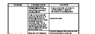
13 MAINTENANCE AND TOWING INSTRUCTIONS NOTE: DO NOT TAMPER WITH UNIT. HAVE A COMPETENT SERVICEMAN MAKE ANY ADJUST- MENTS. NOTE: Before moving guards out of position insure power cord is disconnected. SAFETY WARNING! FAN COULD CYCLE ON AUTOMATICALLY High Limit Switch: The limit switch should be checked every heating season to insure the burner will shut down if temperature exceeds 200 F *This can be done by restricting the air flow through the unit. After tests are complete, remove restrictors as ducts must be open for proper operation. Fan Switch: The adjustable fan switch will turn on the fan when the heat exchanger temperature is at 90 0 F and off at 60 0 F. If the fan fails to stop when the heat exchanger has cooled, replace switch. Fuel Filter: Replace element at least every six months of normal usage, or more frequently in dirty conditions. Flame Detector: The flame detector is located in the burner housing below the transformer. Periodically clean cell detector face with a soft nonabrasive cloth. Burner: The electrode spacing must be checked and adjusted, if necessary, after every nozzle change. Nozzles should be replaced annually or sooner if burner cannot be set up to operate properly. Nozzle size is dependent on altitude of operation. Nozzle size and type are marked on the rating plate. Motors: No lubrication is necessary since the bearings are the sealed type. Fuel System: Do not store unit containing diesel fuel for long periods. NOTE: Service intervals have been established for operation under normal conditions. Where equipment is operated under severe conditions(very dusty, extreme cold, etc.) affected items should be serviced more frequently. For detailed information see the Engine Instruction Manual for Heater Unit Installation-Operating Maintenance instructions. CLEANING PROCEDURE The unit should be cleaned periodically as follows: 1. Remove front cap. 2. Remove cover panel (jacket to front). 3. Remove fan thermostat cover on outer jacket (on the nearest burner). Loosen the ther mostat and remove from the jacket. Remove high limit thermostat. 4. Slide heat exchanger out of jacket and place front face down on floor. 5. Access for combustion chamber and heat exchanger cleaning is obtained through the burner head opening and by removing the heat exchanger cap ring(s). TOWING INSTRUCTIONS Before towing the Maxi Heat, the trailer should be inspected visually to assure that the following operations have been completed: 1. Hitch is securely attached to towing vehicle (safety chain secured). 2. Front jack retracted. 3. Ducting removed from heaters and stored. 4. Doors are closed and secure. 5. Check for adequate tire pressure. 6. Taillights are connected and operating. 7. Remove ground rod from earth and secure in trailer. 12

14 N ot fo rr ep ro du ct io n CLEANING PROCEDURE

15 N ot fo rr ep ro du ct io n CLEANING PROCEDURE


16 TROUBLESHOOTING Electrode Adjustments 13

17 TROUBLESHOOTING 14

18 TROUBLESHOOTING 15

19 TROUBLESHOOTING 16
20 TAILLIGHT WIRING SCHEMATIC 17
21 MAXI-HEAT ELECTRICAL SCHEMATIC 18

22 CONTROL BOX AND GEN SET WIRING 120 VAC 120 VAC 30A 30A FUEL CIRCUIT SCHEMATIC 19
23 ENGINE WIRING SCHEMATIC ISUZU 3CE1 ENGINE 20
24 ENGINE WIRING SCHEMATIC CAT C1.5 ENGINE 21
 for duct installation 16")
")
 installed on connecting band (pn848976) with 16 screw clamp")
25 MAXI-HEAT DUCTWORK INSTALLATION OPTIONS Illustration of lock pin and arrow on 16 slip lock connector (pn848974) for duct installation 16 screw clamp (pn848176) used here to attach duct (pn848172) Duct ready for installation on heater using 16 Slip-Lock Connectors (pn ) Connecting Band (pn848976) for connecting multiple hose lengths 22 Duct (pn848172) installed on connecting band (pn848976) with 16 screw clamp (pn848176)
26 Installation Instructions for Installing the Slip-Lock Duct Connectors (PN #848974) Heater Section Inner Ring 1. Line up the receiver section (ring with slots) inside the heater flange and slide it in to where the small rounded ridge (approximate center of connector ring) is just inside the outer edge of the heater flange. This leaves 11/16 of this inner ring exposed and will allow the compartment door to close freely. Note: Make sure that this alignment remains constant all the way around the outer edge of the flange. 2. Mark the locations of the (3) 3/16 holes and remove the receiver section from the heater flange. Using a center punch, make a dimple in the center of each mark and drill each hole out using a 3/16 drill bit. 3. Re-install the receiver section into the heater flange and connect it (large head inside heater flange) using a pop-rivet gun and (3) 3/16 pop-rivets. Duct-Work Section Outer Ring 1. Slide the end-cuff of the ducting over the larger outer ridge and stop when the cuff makes contact with the small inner ridge (approximate center of connector ring). This leaves 1 of the outer ring exposed. Note: Make sure that this alignment remains constant all the way around the outer ring. 2. Using a scratch awl, poke a hole through the ducting at the location of each of the (3) 3/16 holes and attach the ducting (large head on outside of duct-work) to the outer ring using a pop rivet gun and (3) 3/16 pop rivets 3. Take the 16 screw clamp (PN #848176) and install it right over the top of the (3) 3/16 rivets on the outer ring and tighten down securely on the ducting. Note: Make sure that this alignment remains constant all the way around the outer ring before tightening. 4. Your ductwork is now ready to be connected to the heater unit. 3/16 Pop Rivet Heads directly under screw clamp 11/16 11/ /16 Pop Rivet Head Inside Flange (Body Out) 23
27 PARTS MANUAL SEPTEMBER 2011 MAXI-HEAT SERIES MODEL MH 1000 Beginning with Serial Number 0001MXH09 ALLMAND BROS. INC P.O. BOX 888 HOLDREGE, NE PHONE: 308/ , 1-800/ FAX: 308/ PARTS FAX: 308/ MAXI-HEAT SERIES REV H-1 IDF 500 For Parts and Updates visit Allmand on the Web at
28 TRAILER ASSEMBLY PARTS AND ACCESSORIES A-1A
29 TRAILER ASSEMBLY PARTS AND ACCESSORIES A-1B REF# PART# DESCRIPTION JACK SIDE CRANK SAFETY CHAIN KIT (2 KITS REQUIRED) * REVERSIBLE HITCH ASSEMBLY * BULLDOG HITCH ONLY NS BULLDOG HITCH REPAIR KIT REFLECTOR, AMBER (2 REQUIRED) REPLACEMENT LOCK PIN NS PLASTIC JACK CAP LEGEND: NS = Not Shown ** = Purchase Locally


30 TRAILER ASSEMBLY PARTS AND ACCESSORIES A-2A
31 TRAILER ASSEMBLY PARTS AND ACCESSORIES REF# PART# DESCRIPTION NS P ROOF PANEL P ROOF PANEL 2 (AFTER 0104MXH06) P ROOF PANEL REAR ISUZU NS P ROOF PANEL REAR CAT P ROOF PANEL CENTER ISUZU NS P ROOF PANEL FRONT P ROOF PANEL - FRONT (AFTER 0104MXH06) P SIDE DOOR ASSEMBLY RIGHT P SIDEPANEL RIGHT REAR ISUZU NS P SIDEPANEL RIGHT REAR CAT P SIDE REAR PANEL - RIGHT P SIDE FRONT PANEL - RIGHT NS P SIDE TOP PANEL RIGHT P SIDE TOP PANEL - RIGHT (AFTER 0104MXH06) P SIDE BOTTOM PANEL RIGHT P REAR BUMPER NS P REAR BUMPER SPACER, 2 REQ D TAILLIGHT, 2 REQ D NS TAILLIGHT/INTERLOCK WIRE HARNESS REFLECTOR, RED (2 REQUIRED) X 18 CHIMNEY (stainless steel) CHIMNEY RAIN CAP (stainless steel) NS CHIMNEY VENT GRAB DOOR LATCH ASSEMBLY (INTERCHANGEABLE) P SIDE DOOR ASSEMBLY LEFT (19 1/2 H) P SIDE PANEL LEFT REAR ISUZU NS MANUAL STORAGE BOX P SIDE BOTTOM PANEL LEFT P DOOR FILLER - LEFT P TOP HEADER LEFT (AFTER 0104MXH06) NS TOP HEADER - LEFT P REAR DOOR ASSEMBLY P AIR INTAKE COVER ISUZU DOOR STOP BUMPER JACK SIDE CRANK P FRONT ACCESS PANEL (AFTER 0001MXH07) NS P FRONT ACCESS PANEL (0001MXH06 THRU 0216MXH06) A WHEEL AND TIRE ASSY 15 X 6 6-HOLE OUTER FENDER NS WHEEL ONLY 15 X 6 6-HOLE NS TIRE ONLY ST225/75R15BD NS WIRING HARNESS LEGEND: NS = Not Shown ** = Purchase Locally A-2B


32 TRAILER ASSEMBLY PARTS AND ACCESSORIES A-3A a 40 44
33 TRAILER ASSEMBLY PARTS AND ACCESSORIES REF# PART# DESCRIPTION OUTLET BOX ONLY NS OUTLET BOX RUBBER MOUNT CIRCUIT BREAKER SP, 30 AMP CIRCUIT BREAKER SP, 30 AMP INTERIOR LAMP FIXTURE (HEATER COMPARTMENT) 40A INTERIOR LAMP FIXTURE (ENGINE COMPARTMENT) POSITIVE DOOR HOLDER INTERLOCK SAFETY SWITCH FROST FIGHTER HEATER (2 REQ D) (IDF500HS after 0001MXH09) NS POWER CABLE, REAR HEATER NS POWER CABLE, FRONT HEATER NS FRONT HEATER FUEL SUPPLY LINE, , 81 NS FRONT HEATER FUEL RETURN LINE, , 86 NS REAR HEATER FUEL SUPPLY LINE, , 42 NS REAR HEATER FUEL RETURN LINE, , 49 NS REMOTE THERMOSTAT AXLE/SPRING/HUB ASSEMBLY HUB/BEARING ASSEMBLY FOR LEGEND: NS = Not Shown ** = Purchase Locally A-3B


34 HEATER ASSEMBLY PARTS AND ACCESSORIES B-1A
35 HEATER ASSEMBLY PARTS AND ACCESSORIES REF# PART# DESCRIPTION B-1B NS HEATER ASSEMBLY (IDF500HS after 0001MXH09) HIGH LIMIT SWITCH 200 PROBE HIGH SWITCH COVER B CAD CELL FLAME DETECTOR NS TOGGLE SWITCH NS SWITCH RECEPTACLE A OIL PUMP PRIMARY CONTROL NS PLASTIC COVER FOR A NS GEN. SYSTEM OIL PRIMARY CONTROL STARTED W/ 2012 PRODUCT NS STAINLESS STEEL HEAT EXCHANGER ASSEMBLY B ADJUSTABLE FAN SWITCH NS ADJUSTABLE TEMPERATURE FEELER SWITCH FAN MOTOR, 1.5 HP BALDOR 3/26/09 NS FAN BLADE HIGH STATIC NS FUSE HOLDER NS FUSE, 15 AMP NS AMP THERMO SWITCH NS ADAPTER NIPPLE FOR FUEL SHUTOFF A SPIN ON FUEL FILTER NS A SPIN ON FUEL FILTER AND FILTER HEAD ASSEMBLY NS A MOUNTING BRACKET FOR A FAN MOTOR MOUNT WITH SCREEN FLUE COLLAR FUEL SHUTOFF VALVE COMBU VALVE FUEL GAUGE HEATER PRE-FILTER ASSEMBLY FILTER ELEMENT FOR HEATER ELEMENT FOR NS FUEL PRESSURE GAUGE ONLY NS x 1 INSULATED END CAP NS X 2 INSULATED END CAP NS RETAINER NUT W/ WASHER SET OF 24 NS STAINLESS STEEL HEAT EXCHANGER NS COOPER LINE 9.5" NS COPPER LINE 8" NS CLEAR HOSE W/ FITTING NS GAUGE 200


36 HEATER ASSEMBLY PARTS AND ACCESSORIES B-2A
37 HEATER PARTS AND ACCESSORIES B-2B REF# PART# DESCRIPTION B A FUEL PUMP BURNER MOTOR, 1/3 HP BURNER/BLOWER FAN OIL DELIVERY TUBE OIL DELIVERY TUBE 9-1/ B BECKETT TRANSFORMER/IGNITOR FLEX COUPLING 2 3/4 long (1/4 and 1/2 dia. ends) BURNER ASSEMBLY (IDF 500, CF 800) HOUSING AIR TUBE COMBINATION (includes blast tube, electrode assy, and air diffuser) AIR BAND ASSEMBLY B AIR SHUTTER HOUSING ELECTRODE INSULATOR KIT ELECTRODE ASSEMBLY WITH END CONE COMBO VALVE AIR GUIDE NS B CAD CELL FLAME DETECTOR NS NOZZLE, 2.25 GPH NS A NOZZLE, 2.0 GPH NS B NOZZLE, 2.5 GPH NS C NOZZLE, 2.75 GPH NS NOZZLE, 3.0 GPH NS A NOZZLE, 3.25 GPH NS SMOKE TESTER LEGEND: NS = Not Shown ** = Purchase Locally


38 ENGINE ASSEMBLY AND CONTROL PANEL-ISUZU C-1A
39 ENGINE ASSEMBLY AND CONTROL PANEL-ISUZU REF# PART# DESCRIPTION ISUZU 3CE1 ENGINE ONLY C-1B kW AVR NO CAPACITOR (11/10) NS RECTIFIER BRIDGE ISUZU NEWAGE 3 *** INSTRUMENT PANEL ASSEMBLY, ISUZU IGNITION SWITCH ISUZU WITHOUT TUMBLER OR KEYS NS IGNITION TUMBLER WITH 2 KEYS NS IGNITION KEY ONLY ISUZU HOUR METER. NS CORD CONNECTOR, 3/4 NS NYLON BATTERY HOLD DOWN, 2 REQ D NS BATTERY HOLD DOWN J BOLT MUFFLER, ISUZU 3CD NS ISUZU 3CD MUFFLER GASKET/ CE/ CB AIR INTAKE HOSE FOR ISUZU AIR CLEANER ISUZU CONTROL BOX COVER GLOW LIGHT INDICATOR OIL FILTER ISUZU AIR CLEANER ASSEMBLY NS AIR FILTER ELEMENT ISUZU NS GROUND STRAP * FUEL TANK, 200 GALLON NS FUEL PICKUP TUBE (7/16 X 32.5 ) Qty 4 required NS FUEL PICKUP TUBE (7/16 X 33 ) Qty 2 required NS FUEL TANK CAP NS FUEL GAUGE NS GLOW PLUG TIMER NS RELAY ASSEMBLY NS GENERATOR MOUNT PLATE NEWAGE PERKINS NS FEUL FILTER ISUZU NS BATTERY CABLE 2 GA 48 NS BATTERY CABLE 2GA 36 NS CD ENGINE BLOCK HEATER NS OIL PRESSURE SWITCH NS TEMPERATURE SWITCH NS STOP SOLENOID NS O-RING STOP SOLENOID NS FUEL PUMP NS ALTERNATOR DIODE NS RADIATOR ISUZU 3CD NS AVR BOARD NS ISUZU RADIATOR MOUNTING BRACKET NS ENGINE BLOCK HEATER (4LE/3CD) NS CD/3CE STARTER NS FUMOTO OIL VALVE LEGEND: NS=NOT SHOWN **=PURCHASED LOCALLY ***=CALL ALLMAND FOR LOCAL ISUZU DEALER


40 ENGINE ASSEMBLY AND CONTROL PANEL-CAT C-2A
41 ENGINE ASSEMBLY AND CONTROL PANEL-CAT REF# PART# DESCRIPTION CAT C1.5 ENGINE ONLY GENERATOR ONLY 9kW CAT (AFTER 11/10 3 *** INSTRUMENT PANEL IGNITION SWITCH WITH 2 KEYS C-2B NS IGNITION KEY ONLY NS IGNITION SWITCH W / KEYS 1105/C1.1 AFTER 2/1/10 NS IGNITION KEYS 905 (PAIR) AFTER 2/1/ HOUR METER. NS CORD CONNECTOR, 3/4 NS NYLON BATTERY HOLD DOWN, 2 REQ D NS BATTERY HOLD DOWN J-BOLT MUFFLER, CAT C1.5 MXH 7 ### AIR INTAKE HOSE FOR CAT AIR CLEANER OIL FILTER CAT 9 ### AIR CLEANER ASSEMBLY NS AIR FILTER ELEMENT CAT NS FUEL FILTER CAT NS GROUND STRAP P FUEL TANK, 200 GALLON NS FUEL PICKUP TUBE (7/16 X 32.5 ) Qty 4 required NS FUEL PICKUP TUBE (7/16 X 33 ) Qty 2 required NS FUEL TANK CAP NS GENERATOR MOUNT PLATE NS BATTERY CABLE 2 GA 48 NS BATTERY CABLE 2GA 36 NS ### FUEL PUMP NS ENGINE BLOCK HEATER LEGEND: NS = Not Shown ** = Purchase Locally *** = Call Allmand for Information ### =See Local CAT Dealer
42 OPTIONAL PARTS AND ACCESSORIES D-1A
43 OPTIONAL PARTS AND ACCESSORIES D-1B PART# DUCT STORAGE BOX COMPLETE NO. QTY. PART NO. DESCRIPTION DUCT STORAGE BOX COMPLETE PNL BOTTOM P PNL TOP HINGE PNL FRONT HASP P PNL SDE LF P PNL SIDE RT P LID WELDED MOUNT PLATE X 3/4 SL-FHMS NYLOCK NUT /4-20 X 1/2 RHSSNBOLT /4-20 KEPS NUT /4-20 X 3/4 RHSSN BOLT /8-16 X 1 1/4 HHCS /8 SAE FLAT WASHER /8-16 NYLOCK NUT X 1/2 RHMS DOOR HOLDER LEGEND: NS = Not Shown ** = Purchase Locally


44 OPTIONAL PARTS AND ACCESSORIES D-2A
45 OPTIONAL PARTS AND ACCESSORIES D-2B REF# PART# DESCRIPTION SLIP LOCK CONNECTOR HEATER DUCT 16 X 20 NS HEATER DUCT 12 X CONNECTING BAND SCREW CLAMP NS SCREW CLAMP x 1 INSULATED END CAP X 2 INSULATED END CAP NS HEATER DUCT 16 X 10 W SILICONE LINER LEGEND: NS = Not Shown ** = Purchase Locally
46 DECALS E-1A PART# QTY DESCRIPTION (ENGLISH) MAXI HEAT DECAL SET, COMPLETE (INCLUDES ALL OF THE DECALS LISTED BELOW) MAXI HEAT STRIPE DECAL SET, COMPLETE (5 PCS.) DECAL HOT, DO NOT TOUCH GRIPTAPE, FENDER DECAL 40 DUCT ONLY DECAL DIESEL ONLY DECAL WARNING, FAILURE TO USE DECAL HEATER OPERATING INSTRUCTIONS DECAL ENGINE START PROCEDURE DECAL DO NOT OPERATE INSIDE DECAL DO NOT OPERATE DECAL-PROPOSITION 65 DIESEL DECAL-GROUND LUG DECAL-OPERATORS MANUAL DECAL-ATTENTION NOZZLE SIZE ALLMAND ASSURANCE MADE IN USA FOR PARTS AND SERVICE CONTACT ALLMAND.COM ELECTRIC SHOCK HAZARD INTERIOR LIGHT OPERATION UNIT SPECIFICATIONS GENERAL CAUTION STATEMENTS GROUND ROD USE INSTRUCTIONS LEGEND: NS = Not Shown ** = Purchase Locally
47 CAT C1.5 ENGINE WIRING BLACK HOUR - + METER AUTO SHUTDOWN CONTROLLER GROUND STUD Diode BLUE 3 Watt 65 OHM Resistor OIL PRESSURE SWITCH BLACK ALTERNATOR D+ W BLACK 6 BLACK B+ BROWN 4 BROWN/ORANGE BLACK BLUE 5 GRAY RED PINK B 1 ORANGE 2 ORANGE RED/BLACK HIGH WATER TEMPERATURE SWITCH RED 3 GREEN PURPLE RED YELLOW 15 AMP FUSE YELLOW INTERIOR LIGHT TOGGLE SWITCH PINK AC KEY SWITCH AMP FUSE ENGINE BLOCK 19 CASE GROUND BLUE 68" 12 GA BLACK 30 AMP BREAKER GLOW PLUGS Diode #2 RED YELLOW RED PINK SAFETY ENGINE KILL WHEN DOOR CLOSED Diode #1 YELLOW DOOR SWITCH - BATTERY + STARTER MOTOR S ORANGE FUEL SOLENOID YELLOW BLACK BLACK REAR 12V LAMP FRONT 12V LAMP STARTER MOTOR BOLT
48 Allmand Bros. Inc. PO Box West 4 th Ave Holdrege, NE / Fax / MAXI-HEAT LIMITED WARRANTY ADDENDUM THIS IS AN ADDENDUM TO THE BASIC ALLMAND LIMITED WARRANTY OF ONE (1) YEAR AFTER DELIVERY TO THE ORIGINAL PURCHASER. The following manufacturers limited warranty policy warrants their components to be free from defects in material and workmanship from date of manufacture as follows (see specific manufacturer s warranty for details): ISUZU TWO (2) YEARS 2000 HOURS Includes all Isuzu model 3-C engines As of No representative, dealer, or distributor of the company is authorized to make any changes or exceptions to this warranty unless expressly authorized in writing from the manufacturer. All warranty claims must be filed within thirty (30) days of failure. Please call the Allmand Service and Warranty Department for specific manufacturer s warranty terms and schedules. All warranties are subject to change without notice. Limited Warranty Maxi-Heat Addendum 4/08
49 LIMITED WARRANTY ALLMAND MAXI-HEAT LIMITED WARRANTY UNITED STATES and U.S. TERRITORIES THIS WARRANTY IS IN LIEU OF ALL OTHER WARRANTIES, EXPRESSED OR IMPLIED INCLUDING WARRANTIES OF MERCHANTABILITY OR OF FITNESS FOR PURPOSE, AND ANY EXCEPTIONS ARE DESCRIBED IN THE PUBLISHED LIMITED WARRANTY ADDENDUM, AVAILABLE UPON REQUEST. COMPONENTS, SUB-ASSEMBLIES, AND DEVICES MANUFACTURED BY OTHER MANUFACTURERS ARE NOT COVERED BY THIS WARRANTY. ALL WARRANTY INFORMATION FROM SUCH OTHER MANUFACTURERS IS PROVIDED WITHIN OR ACCOMPANY THESE GOODS. Subject to the foregoing, the manufacturer, Allmand Bros. Inc., hereby warrants all equipment manufactured by Allmand Bros. Inc. to be free from defects in material and workmanship for a period of (1) year after delivery to the original purchaser. Additionally, Allmand Bros. Inc. hereby warrants all replacement parts supplied by Allmand Bros. Inc. to be free from defects in material and workmanship for a period of 90 days after date of invoice. Delivery shall be deemed for the purposes of this warranty to have occurred no later than five days following the date of sale agreement or invoice unless the purchase agreement or invoice specifically states a later delivery date in which case such delivery date shall control. The original purchaser shall be deemed to be a person who places the goods or products in actual use, and any person holding such goods solely for wholesale or retail sale purposes shall not constitute an original purchaser. PROVIDED, any leasing of these goods or other use beyond normal demonstration of same shall be deemed to be in use by an original purchaser and all warranty periods shall commence at the time of such use. During the warranty period any defective goods or parts hereof shall be repaired or replaced at manufacturer s discretion. In the event it is necessary to return such goods or parts to the factory, all transportation charges shall be prepaid. The manufacturer shall in no event pay mileage expenses, but will warrant outbound ground freight. The obligations of the manufacturer is solely to repair or replace defective goods or parts or to refund the cost of the same if it is determined by the manufacturer that repair or replacement will not return the goods to proper working order or utility. THE REMEDIES SET FORTH HEREIN ARE EXCLUSIVE AND MANUFACTURER SHALL NOT BE LIABLE FOR SPECIAL, INDIRECT, OR CONSEQUEN- TIAL DAMAGES. THE OBLIGATIONS OF THE MANUFACTURER HEREUNDER SHALL IN NO WAY EXCEED THE PRICE OF THE EQUIPMENT OR PART UPON WHICH SUCH LIABILITY IS BASED. The warranty shall not extend to tires, lamps, batteries, or parts that have been altered, changed, damaged, or improperly installed, repaired, operated or maintained. Provided, this exclusion shall not apply to installations, repairs or other work done at the manufacturer s plant or under direct manufacturer s supervision. The Operator s Manual, to the extent covered therein, is deemed to set forth the proper procedures for operation, repair, installation, and maintenance of these goods. No representative, dealer or distributor of the company is authorized to make any changes or exceptions to this warranty unless expressly authorized in writing from the manufacturer. All warranty claims must be filed within forty-five (45) days of the failure. ALLMAND BROS. INC., 1502 W 4 TH AVENUE, P.O.BOX 888, HOLDREGE, NE (308) ALLMAND LIMITED WARRANTY 1YR MAXI HEAT doc
 YEAR AFTER DELIVERY TO THE ORIGINAL PURCHASER.")
50 Allmand Bros. Inc. PO Box West 4 th Ave Holdrege, NE / Fax / MAXI-HEAT LIMITED WARRANTY ADDENDUM THIS IS AN ADDENDUM TO THE BASIC ALLMAND LIMITED WARRANTY OF ONE (1) YEAR AFTER DELIVERY TO THE ORIGINAL PURCHASER. The following manufacturers limited warranty policy warrants their components to be free from defects in material and workmanship from date of manufacture as follows (see specific manufacturer s warranty for details): ISUZU 3CD1* TWO (2) YEARS 2000 HOURS CATERPILLAR C1.5 TWO (2) YEARS 2000 HOURS CUMMINS ONE (1) YEAR -- *Includes all Isuzu model 3-C engines As of No representative, dealer, or distributor of the company is authorized to make any changes or exceptions to this warranty unless expressly authorized in writing from the manufacturer. All warranty claims must be filed within thirty (30) days of failure. Please call the Allmand Service and Warranty Department for specific manufacturer s warranty terms and schedules. All warranties are subject to change without notice. Limited Warranty Maxi-Heat Addendum 11/12
51
PARTS CATALOG. Maxi-Heat MH Part No SN 0001MXH12 and UP. (308) , (800) (308) (308)
 , (800) (308) (308)") Maxi-Heat MH 000 N ot fo rr ep ro du ct io n PARTS CATALOG PHONE FAX PARTS DEPT. FAX WEB (08) 99-9, (800) -7 (08) 99-887 (08) 99-88 www.allmand.com Part No. 0807 TABLE OF CONTENTS.0 MAXI-HEAT TRAILER ASSEMBLY
Maxi-Heat MH 000 N ot fo rr ep ro du ct io n PARTS CATALOG PHONE FAX PARTS DEPT. FAX WEB (08) 99-9, (800) -7 (08) 99-887 (08) 99-88 www.allmand.com Part No. 0807 TABLE OF CONTENTS.0 MAXI-HEAT TRAILER ASSEMBLY
MAXI-LITE V-SERIES ML 7.5/ML 8 OPERATOR S MANUAL ALLMAND BROS. INC P.O. BOX 888 HOLDREGE, NE 68949
 MAXI-LITE V-SERIES ML 7.5/ML 8 OPERATOR S MANUAL ALLMAND BROS. INC P.O. BOX 888 HOLDREGE, NE 68949 PHONE: 308/995-4495, 1-800/562-1373 ALLMAND FAX: 308/995-5887 ALLMAND PARTS FAX: 308/995-4883 MAXI-LITE
MAXI-LITE HYDRAULIC TOWER 683, 695, 883, 895, and 895XL OPERATOR S MANUAL ALLMAND BROS. INC P.O. BOX 888 HOLDREGE, NE 68949
 MAXI-LITE HYDRAULIC TOWER 683, 695, 883, 895, and 895XL OPERATOR S MANUAL ALLMAND BROS. INC P.O. BOX 888 HOLDREGE, NE 68949 PHONE: 308/995-4495, 1-800/562-1373 ALLMAND FAX: 308/995-5887 ALLMAND PARTS FAX:
NIGHT-LITE PRO V SERIES VERTICAL TOWER OPERATOR S MANUAL ALLMAND BROS. INC P.O. BOX 888 HOLDREGE, NE 68949
 NIGHT-LITE NIGHT-LITE PRO V SERIES VERTICAL TOWER OPERATOR S MANUAL ALLMAND BROS. INC P.O. BOX 888 HOLDREGE, NE 68949 PHONE: 308/995-4495, -800/56-373 ALLMAND FAX: 308/995-5887 ALLMAND PARTS FAX: 308/995-4883
MAXI-LITE HYDRAULIC TOWER 683, 695, 883, 895, 895XL PARTS MANUAL ALLMAND BROS. INC P.O. BOX 888 HOLDREGE, NE 68949
 MAXI-LITE HYDRAULIC TOWER 683, 695, 883, 895, 895XL PARTS MANUAL ALLMAND BROS. INC P.O. BOX 888 HOLDREGE, NE 68949 PHONE: 308/995-4495, 1-800/562-1373 ALLMAND FAX: 308/995-5887 ALLMAND PARTS FAX: 308/995-4883
ML EX V SERIES 20KW / 30KW DOMESTIC MODEL 2010 ALLMAND BROS. INC. P.O. BOX 888 HOLDREGE, NE, USA 68949
 ML EX V SERIES 20KW / 30KW DOMESTIC MODEL 200 ALLMAND BROS. INC. P.O. BOX 888 HOLDREGE, NE, USA 68949 PHONE: (308)995-4495, -(800)562-373 ALLMAND FAX: (308) 995-5887 ALLMAND PARTS FAX: (308) 995-4883 ML
6330 AND 8330 OPERATOR S MANUAL ALLMAND BROS. INC P.O. BOX 888 HOLDREGE, NE 68949
 NIGHT-LITE 6330 AND 8330 OPERATOR S MANUAL ALLMAND BROS. INC P.O. BOX 888 HOLDREGE, NE 68949 PHONE: 308/995-4495, 1-800/562-1373 ALLMAND FAX: 308/995-5887 ALLMAND PARTS FAX: 308/995-4883 NIGHT- LITE SERIES
for Reproduction Not Brighter. Warmer. Safer. Portable Industrial Heaters Portable Light Towers Portable Light Stands Solar Flashing Arrow Boards
 Brighter. Warmer. Safer. Portable Industrial Heaters Portable Light Towers Portable Light Stands Solar Flashing Arrow Boards en Copyright 06 Allmand Bros., Inc. Holdrege, NE, USA. All rights reserved.
SELECT DIAGNOSTIC GUIDE. INST028 Doc 3.02
 SELECT DIAGNOSTIC GUIDE INST028 Doc 3.02 CONTENTS General Information...2 Select Call-Outs...3 Wire Diagram and Legend...4 Diagnostics...6 Excessive Voltage Drop Diagnostics...6 Static Diagnostics...7
Oil - kerosene burner
 Installation, use and maintenance instructions Oil - kerosene burner One stage operation CODE MODEL TYPE 374445 G5 444T50 9038 () TECHNICAL FEATURES Thermal power output 8 0 kw.3 5 kg/h Fuel Gas oil 35s,
RED23305 Owner s Manual
 RED23305 Owner s Manual 5 foot, 3-Point Mounted Snow Blower 270 West Park Avenue Huron, SD 57350 866-526-5682 Serial Number: Date of Purchase: Red Devil Snow Blower See Figure 1. 1. The Red Devil Snow
ADI-125/750 ADI-125/1500 ADI-125/2500
 Manufacturer of Dimensions TM Inverters 4467 White Bear Parkway St. Paul, MN 55110 Phone: 651-653-7000 Fax: 651-653-7600 E-mail: inverterinfo@sensata.com Web: www.dimensions.sensata.com 121094B OWNERS
Dimensions 12/800N 12/1200N D. DC to AC Power Inverters. OWNERS MANUAL for Models: OWNERS MANUAL April ISO 9001:2000 Certified Company
 Manufacturer of Dimensions Inverters 4467 White Bear Parkway St. Paul, MN 55110 Phone: 651-653-7000 Fax: 651-653-7600 E-mail: inverterinfo@sensata.com Web: www.dimensions.sensata.com OWNERS MANUAL April
HVF110, 210, 310, 410HD
 342 N. Co. Rd. 400 East Valparaiso, IN 46383 219-464-8818 Fax 219-462-7985 www.heatwagon.com Installation and Maintenance Manual Please retain this manual for future reference. HVF110, 210, 310, 410HD
NIGHT-LITE PRO PARTS MANUAL
 NIGHT-LITE PRO PARTS MANUAL Serial Number 1978PRO08 and Up ALLMAND BROS. INC P.O. BOX 888 HOLDREGE, NE 68949 PHONE: 308/995-4495, 1-800/562-1373 ALLMAND FAX: 308/995-5887 ALLMAND PARTS FAX: 308/995-4883
Operating and Assembly Manual
 Model 470-/H/PRO/IC Operating and Assembly Manual Midwest Equipment Manufacturing, Inc. 5225 Serum Plant Road Thorntown, IN 46071 11-11-11 SAFETY RULES Remember, any power equipment can cause injury if
1200+ WITH LVD (LOW VOLTAGE DISCONNECT) USER GUIDE
 USER GUIDE") 1200+ WITH LVD (LOW VOLTAGE DISCONNECT) USER GUIDE INST045 Doc 2.00 CONTENTS General Information...2 Operating Environment...6 Features...7 Installation Instructions...8 Inverter Ground and Remote Sense
1200+ WITH LVD (LOW VOLTAGE DISCONNECT) USER GUIDE INST045 Doc 2.00 CONTENTS General Information...2 Operating Environment...6 Features...7 Installation Instructions...8 Inverter Ground and Remote Sense
Operating and Assembly Manual
 Model 1080 Operating and Assembly Manual Midwest Equipment Manufacturing, Inc. 5225 Serum Plant Road Thorntown, IN 46071 08-02-16 SAFETY RULES Remember, any power equipment can cause injury if operated
INSTRUCTION MANUAL L WIND CONE
 Cooper Industries DOCUMENT September 29, 2009 Revision B Crouse-Hinds Division Crouse-Hinds Airport Lighting Products 1200 Kennedy Road Windsor, CT 06095 860 683-4300 Fax 860 683-4354 Title: INSTRUCTION
CRD610 Automatic Fitting Inserter
 CRD610 Automatic Fitting Inserter OPERATIONS MANUAL VERSION 1.2 LAST EDITED 12.12.2018 cleanroomdevices.com 1 Table of Contents Title Page. 1 Table of Contents...2 1.0 General Product & Safety Information....3
CAPACITOR ACTUATED PORTABLE STARTER CAPS USER GUIDE. INST048 Doc 3.01
 CAPACITOR ACTUATED PORTABLE STARTER CAPS USER GUIDE INST048 Doc 3.01 CONTENTS General Information...2 Charts...3 Before First Use...4 Safety Requirements...5 What to Expect from the CAPS...5 CAPS Diagram...6
Extension Hopper Installation & Operator s Instruction Manual for Model 55, 75, 90, & HMC FLEX-AUGER Feed Delivery Systems
 Extension Hopper Installation & Operator s Instruction Manual for Model 55, 75, 90, & HMC FLEX-AUGER Feed Delivery Systems April 02 Chore-Time Warranty Chore-Time Equipment warrants each new product manufactured
DIRECT PLUS/FLEX/MAX INSTALLATION GUIDE. INST165 Doc 1.04
 DIRECT PLUS/FLEX/MAX INSTALLATION GUIDE INST165 Doc 1.04 CONTENTS General Information...2 Diagrams...3 Mounting the Direct Nosebox...5 Main Harness Installation...6 Interior Light Harness Installation...10
Model 452-DIC/DH. Operating and Assembly Manual
 . Model 452-DIC/DH Operating and Assembly Manual Palmor Products Inc. 5225 Serum Plant Road Thorntown, IN 46071 02-14-12 SAFETY RULES Remember, any power equipment can cause injury if operated improperly
Model ET 5000W Operation and Service Manual
 Model ET 5000W Operation and Service Manual Patented 5/16 BALL Load Capacity: 5000 lbs The ET 5000W ESCALATE TRAILER offers ground level roll-on loading and roll-off unloading of equipment with non-tilting
Parts Manual V100G Vacuum Machine Part #E (SERIAL #1G G )
") 2006 Perimeter Road. Greenville, SC 29605 Toll Free: 800/435-9340 - Phone: 864/277-5870 Fax: 864/235-9661 - Website address: www.mightymole.com Email address: mmole@mightymole.com Parts Manual V100G Vacuum
2006 Perimeter Road. Greenville, SC 29605 Toll Free: 800/435-9340 - Phone: 864/277-5870 Fax: 864/235-9661 - Website address: www.mightymole.com Email address: mmole@mightymole.com Parts Manual V100G Vacuum
DC to AC Power Inverters
 Manufacturer of Dimensions TM Inverters 4467 White Bear Parkway St. Paul, MN 55110 Phone: 651-653-7000 Fax: 651-653-7600 E-mail: inverterinfo@sensata.com Web: www.dimensions.sensata.com 121114C OWNERS
CRD600 Automatic Fitting Inserter
 CRD600 Automatic Fitting Inserter OPERATIONS MANUAL VERSION 2.3 LAST EDITED 12.07.2018 cleanroomdevices.com 1 Table of Contents Title Page.. 1 Table of Contents. 2 1.0 General Product & Safety Information...3
MIL-24/2600Q MIL-24/3200DQ
 Manufacturer of Dimensions TM Inverters 4467 White Bear Parkway St. Paul, MN 55110 Phone: 651-653-7000 Fax: 651-653-7600 E-mail: inverterinfo@sensata.com Web: www.dimensions.sensata.com 121473B OWNER'S
for Reproduction Not Brighter. Warmer. Safer. Portable Industrial Heaters Portable Light Towers Portable Light Stands Solar Flashing Arrow Boards
 Brighter. Warmer. Safer. Portable Industrial Heaters Portable Light Towers Portable Light Stands Solar Flashing Arrow Boards en Copyright 06 Allmand Bros., Inc. Holdrege, NE, USA. All rights reserved.
MODEL 5120 Tire Repair Station
 MODEL 5120 Tire Repair Station 00-0049 Installation, Operation & Repair Parts Information Branick Industries, Inc. 4245 Main Avenue P.O. Box 1937 Fargo, North Dakota 58103 REV01182017 P/N: 81-0058G CAUTION
SELECT -24 INSTALLATION GUIDE. INST036 Doc 2.02
 SELECT -24 INSTALLATION GUIDE INST036 Doc 2.02 CONTENTS General Information...2 Select-24 Diagram...3 Mounting the Select Controller...4 Dual Pole Nosebox Installation...5 Aux Harness Installation...6
OWNERS MANUAL JANUARY 2007 ISO
 Manufacturer of Dimensions TM Inverters 4467 White Bear Parkway St. Paul, MN 55110 Phone: 651-653-7000 Fax: 651-653-7600 E-mail: inverterinfo@sensata.com Web: www.dimensions.sensata.com OWNERS MANUAL JANUARY
Instruction Manual. Fudge Puppy Display Case
 Instruction Manual Fudge Puppy Display Case Model No. 5535 10700 Medallion Drive, Cincinnati, Ohio 45241-4807 USA 2014 Gold Medal Products Co. Part No. 89074 SAFETY PRECAUTIONS DANGER Machine must be properly
Light oil - kerosene burner
 Installation, use and maintenance instructions Light oil - kerosene burner One stage operation CODE MODEL TYPE 3747455 G0KI 474T5 90403 (4) - 0/008 TECHNICAL DATA Thermal power output 95 3 kw 8 8 kg/h
CLEAN ROOM DEVICES, LLC "WHERE TUBING AND FITTINGS COME TOGETHER"
 CLEAN ROOM DEVICES, LLC "WHERE TUBING AND FITTINGS COME TOGETHER" CRD600 Automatic Fitting Inserter OPERATIONS MANUAL VERSION 2.1 LAST EDITED 7.25.14 DOCUMENT NUMBER 001 cleanroomdevices.com 1 Table of
DC to AC Power Inverters
 Manufacturer of Dimensions TM Inverters 4467 White Bear Parkway St. Paul, MN 55110 Phone: 651-653-7000 Fax: 651-653-7600 E-mail: inverterinfo@sensata.com Web: www.dimensions.sensata.com ISO 9001:2000 Certified
Operating and Assembly Manual
 Model 455-IC/PRO/H Operating and Assembly Manual Midwest Equipment Manufacturing, Inc. 5225 Serum Plant Road Thorntown, IN 46071 03-08-12 SAFETY RULES Remember, any power equipment can cause injury if
TRAILER AUXILIARY POWER SYSTEM (TAPS) INSTALLATION GUIDE V1.10
 INSTALLATION GUIDE V1.10") TRAILER AUXILIARY POWER SYSTEM (TAPS) INSTALLATION GUIDE V1.10 TAPS INSTALLATION GUIDE V1.10 1 TRAILER AUXILIARY POWER SYSTEM CONTENTS General Information and System Logic... 2 Diagrams... 3 System Diagram
TRAILER AUXILIARY POWER SYSTEM (TAPS) INSTALLATION GUIDE V1.10 TAPS INSTALLATION GUIDE V1.10 1 TRAILER AUXILIARY POWER SYSTEM CONTENTS General Information and System Logic... 2 Diagrams... 3 System Diagram
iqpc912 PARTS MANUAL PC912PM v1
 iqpc912 PARTS MANUAL PC912PM v1 See Page 10 See Page 6 & See Page 12 See Page 2 See Page 16 See Page 1 See Page 1 See Page See Page 22 See Page 20 See Page 2 See Page 26 3 16 19 1 17 1 1 11 13 12 10 9
Operating and Assembly Manual
 Model 455-IC/PRO/H Operating and Assembly Manual Palmor Products Inc. 5225 Serum Plant Road Thorntown, IN 46071 03-08-12 SAFETY RULES Remember, any power equipment can cause injury if operated improperly
DISCONTINUED VERSION Parts listed in this catalog may no longer be available. ILLUSTRATED PARTS CATALOG
 BUNN COMBO BREWER DISCONTINUED VERSION Parts listed in this catalog may no longer be available. ILLUSTRATED PARTS CATALOG Designs, materials, weights, specifications, and dimensions for equipment or replacement
CLEAN ROOM DEVICES, LLC "WHERE TUBING AND FITTINGS COME TOGETHER"
 CLEAN ROOM DEVICES, LLC "WHERE TUBING AND FITTINGS COME TOGETHER" CRD600AF Automatic Fitting Inserter With Auto Feed OPERATIONS MANUAL (Shown with optional alcohol dispenser) 1 VERSION 1.1 LAST EDITED
Part Number Mini Linear Lift Assembly Installation & Operator s Instruction Manual
 Part Number 39644 Mini Linear Lift Assembly Installation & Operator s Instruction Manual April 1999 MV1505C Chore-Time Warranty Mini Linear Lift Assembly Manual Chore-Time Warranty Chore-Time Equipment
Parts Manual V100G Vacuum Machine Part #E (SERIAL #1G G )
") 2006 Perimeter Road. Greenville, SC 29605 Toll Free: 800/435-9340 - Phone: 864/277-5870 Fax: 864/235-9661 - Website address: www.mightymole.com Email address: mmole@mightymole.com Parts Manual V100G Vacuum
2006 Perimeter Road. Greenville, SC 29605 Toll Free: 800/435-9340 - Phone: 864/277-5870 Fax: 864/235-9661 - Website address: www.mightymole.com Email address: mmole@mightymole.com Parts Manual V100G Vacuum
INSTALLATION, INSTRUCTION AND SERVICE MANUAL
 INSTALLATION, INSTRUCTION AND SERVICE MANUAL Actuator/Brake/Trailer Dealer Please provide to consumer. Consumer Read and follow instructions. Keep with trailer for reference. Page 1 of 7 1. Introduction...
DISCONTINUED VERSION Parts listed in this catalog may no longer be available. ILLUSTRATED PARTS CATALOG BUNN-O-MATIC CORPORATION
 8 4 0 0 1 BUNN Espress ES 2C DISCONTINUED VERSION Parts listed in this catalog may no longer be available. 12 0,5 1,5 CL 2 16 2,5 CAUTION HOT Liquid-Steam-Surfaces OFF ON ILLUSTRATED PARTS CATALOG Designs,
Kerosene - oil burner
 Installation, use and maintenance instructions Kerosene - oil burner Two stage operation CODE MODEL TYPE 3746686 G0D 76T8 90 (0) TECHNICAL FEATURES Thermal power output 44 / 54 0 kw 3.7 / 4.5 0 kg/h Fuel
MAXI LITE VSERIES HYDRAULIC
 MAXI LITE VSERIES HYDRAULIC 24 2 8 SHO HD 250w LAMPHOLDER 4 4 4 7 32 22 33 5 3 29 28 26 27 2 7 7 4 30 25 20 3 23 3 5 6 9 7 2 6 2 9 0 8 80025373IPL MLA-A SHO HD 250w LAMPHOLDER 3 022060 WIRE CAP SMALL 2
MODEL L/R/EF Sectional Tire Spreader
 MODEL L/R/EF Sectional Tire Spreader Installation, Operation & Repair Parts Information Branick Industries, Inc. 4245 Main Avenue P.O. Box 1937 Fargo, North Dakota 58103 REV08032016 P/N: 81-0195E TABLE
O:\Manuals\TailgateAndBumperMountedLeafVacuums\TruckMountedVacuumsSwingMountManual_rev doc 1
 O:\Manuals\TailgateAndBumperMountedLeafVacuums\TruckMountedVacuumsSwingMountManual_rev.10-30-2017.doc 1 TABLE OF CONTENTS TAILGATE MOUNT LEAF VACUUMS COVER & TABLE OF CONTENTS...Pages 1 2 STATEMENT OF
RAYPAK ILLUSTRATED PARTS LIST
 COMMERCIAL MODELS: MVB 503A THRU 2003A CATALOG NO. 9300.744 Effective: 12-01-17 Replaces: 03-01-17 RAYPAK ILLUSTRATED PARTS LIST MODEL SIZES: 503A, 753A, 1003A, 1253A, 1503A, 1753A & 2003A MODEL TYPES:
OWNERS MANUAL JANUARY 2007 ISO
 Manufacturer of Dimensions TM Inverters 4467 White Bear Parkway St. Paul, MN 55110 Phone: 651-653-7000 Fax: 651-653-7600 E-mail: inverterinfo@sensata.com Web: www.dimensions.sensata.com 121231B OWNERS
COMMERCIAL MODELS: XTHERM 1005A THROUGH 2005A
 COMMERCIAL MODELS: XTHERM 1005A THROUGH 2005A CATALOG NO. 9300.90 Effective: 12-13-13 Replaces: NEW RAYPAK ILLUSTRATED PARTS LIST MODEL SIZES: 1005A, 1505A & 2005A MODEL TYPES: MODULATING VERTICAL BOILER
 Product Name: Product Description: Product Number: Comp-Gate40 40mm External TS-0505-1XXX ------------------------------------------------------------------------------------------------------------------------
OWNER S MANUAL Z SERIES TRACKS. Rev. 355_05
 OWNER S MANUAL Z SERIES TRACKS Rev. 355_05 LOEGERING 800-373-5441 15514 37 th Street SE 701-347-5441 Casselton, ND 58012 USA Fax: 701-347-4323 E-Mail: lmi@loegering.com Internet: www.loegering.com Loegering
CODE MODEL TYPE G3BF 490T G5BF 492T G5BF 489T53
 Installation, use and maintenance instructions Kerosene burners One stage operation CODE MODEL TYPE 3749053 G3BF 490T53 374957 G5BF 49T57 3748953 G5BF 489T53 9036 (6) TECHNICAL FEATURES TYPE - Boiler
Operations and Service Manual. X30208 Load Bank
 Operations and Service Manual Read all instructions before using the load bank Contents 1. Components... 3 Total Assembly... 3 2) Specifications... 4 a)... 4 3) Receiving... 5 4) Safety... 5 a) Ground
BD SUPER B SPECIAL Dodge 5.9L Cummins 24v ISB
 1 This turbo is intended for high performance applications and is not to be used for towing applications BD SUPER B SPECIAL 1994-2002 Dodge 5.9L Cummins 24v ISB Part# 1045120 PLEASE READ ALL INSTRUCTIONS
User Manual. Posture+ Adjustable Base. For customer service call:
 User Manual Posture+ Adjustable Base For customer service call: 1-877-707-7533 1 IMPORTANT INFORMATION PLEASE READ THESE INSTRUCTIONS THOROUGHLY BEFORE USING THIS PRODUCT. PROPER OPERATION OF YOUR ADJUSTABLE
ETP-5E & ETP-10E ECO-TECH PLUS ELECTRIC CONVECTION STEAMER PARTS AND SERVICE MANUAL
 ETP-5E & ETP-10E ECO-TECH PLUS ELECTRIC CONVECTION STEAMER PARTS AND SERVICE MANUAL EFFECTIVE JANUARY 10, 2018 Superseding All Previous Parts Lists. The Company reserves the right to make substitution
RAYPAK ILLUSTRATED PARTS LIST
 RAYPAK ILLUSTRATED PARTS LIST The parts listed are for standard equipment for this model type. Raypak reserves the right to substitute, delete or change any part without notification. The addition of options
Model LA 4400 Time Delay OFF Controller
 ISIMET LA Series Model LA 4400 Time Delay OFF Controller Installation, Operation and Maintenance Manual Application: The Time Delay OFF Controller with integral 24-hr. programmable time clock operates
MODEL A96 SERIES. 130Vdc Switchmode Utility Rectifier / Battery Charger. Used with LaMarche Power Cage ECN/DATE
 MODEL A96 SERIES 130Vdc Switchmode Utility Rectifier / Battery Charger Used with LaMarche Power Cage CPN112138 ECN/DATE ISSUE DATE: ECN 17010-12/05 106 BRADROCK DRIVE DES PLAINES, IL. 60018-1967 (847)
1200+ WITH LVD (LOW VOLTAGE DISCONNECT) V1.00 OWNERS MANUAL
 V1.00 OWNERS MANUAL") 1200+ WITH LVD (LOW VOLTAGE DISCONNECT) V1.00 1 1200+ WITH LVD V1.00 OWNERS MANUAL CONTENTS General Information... 2 Operating Environment... 5 Features... 6 Installation Instructions... 7 Inverter Ground
1200+ WITH LVD (LOW VOLTAGE DISCONNECT) V1.00 1 1200+ WITH LVD V1.00 OWNERS MANUAL CONTENTS General Information... 2 Operating Environment... 5 Features... 6 Installation Instructions... 7 Inverter Ground
Harley Davidson FL Touring Current Xtreme
 ITEMS SUPPLIED Description Part # Qty Front Header (Chr/Blk) 100-0119/100-0123 1 Rear Header (Chr/Blk) 100-0120/100-0124 1 Front Heat Shield (Chr/Blk) 100-0121/100-0125 1 Rear Heat Shield (Chr/Blk) 100-0122/100-0126
Installation / Owners Manual
 DEALER/INSTALLER: (1) Provide this Manual to end user END USER: Part Number: 94621 94622* *Packaged for Individual sale. (1) Read and follow this Manual for Reese Installation. (2) Save this Manual for
Operating and Assembly Manual
 Model 380/385-IC/385-LH Operating and Assembly Manual Midwest Equipment Manufacturing, Inc. 5225 Serum Plant Road Thorntown, IN 46071 2-0916 SAFETY RULES Remember, any power equipment can cause injury
DIAMOND CONCRETE SAW PARTS LIST MODEL CC8000 P R O D U C T S. (Revised )
") DIAMOND P R O D U C T S CONCRETE SAW PARTS LIST MODEL CC8000 (Revised 10-15-2002) Table of Contents Page Saw Controls Legend. 3 Drawing 1. Frame Group. 4-5 Drawing 2. Arm Assembly... 6-7 Drawing 3. Hydraulics
DIAMOND P R O D U C T S CONCRETE SAW PARTS LIST MODEL CC8000 (Revised 10-15-2002) Table of Contents Page Saw Controls Legend. 3 Drawing 1. Frame Group. 4-5 Drawing 2. Arm Assembly... 6-7 Drawing 3. Hydraulics
INSTALLATION INSTRUCTIONS
 INSTALLATION INSTRUCTION AND SERVICE MANUAL Actuator/Trailer Dealer - Please provide these instructions to the consumer. Consumer - Read and follow these instructions. Keep them with the trailer for future
Penguin Gentoo 600B Cordless Sprayer User s Manual
 Penguin Gentoo 600B Cordless Sprayer User s Manual Please read before use. Serial Number: Date of Purchase: Distributor: LIMITED WARRANTY POLICY Masterclean Products, LLC endeavors to provide high quality
Twin Turbo Installation Instructions
 Twin Turbo Installation Instructions Pacific Performance Engineering 303 N Placentia Ave. Fullerton, CA 92831 www.ppediesel.com Legal in California only for racing vehicles which may never be used on the
INSTRUCTIONS SMOKE BLOWER WITH HONDA ENGINE PART NUMBER
 1 INSTRUCTIONS SMOKE BLOWER WITH HONDA ENGINE PART NUMBER 303-568 CHERNE INDUSTRIES INCORPORATED 1-800-THE PLUG 5700 LINCOLN DRIVE (1-800-843-7584) MINNEAPOLIS, MN 55436-1695 FAX: 1-800-843-7585 www.cherneind.com
24/3000H-3PH 24/4500H-3PH 24/6000H-3PH
 Manufacturer of Dimensions TM Inverters 4467 White Bear Parkway St. Paul, MN 55110 Phone: 651-653-7000 Fax: 651-653-7600 E-mail: inverterinfo@sensata.com Web: www.dimensions.sensata.com 120015D OWNERS
Dodge Ram 5.9L Cummins LOW FUEL PRESSURE ALARM LIGHT - Installation Manual -
 29 September 2005 Dodge Cummins Low Fuel Pressure Alarm Light Kit 1081130-33 1 1999-2005 Dodge Ram 5.9L Cummins LOW FUEL PRESSURE ALARM LIGHT - Installation Manual - Part Number Sequence: 1081130 Red 1081133
Model 858-RH. Operating and Assembly Manual. Palmor Products Inc Serum Plant Road Thorntown, IN 46071
 Model 5-RH Operating and Assembly Manual Palmor Products Inc. 55 Serum Plant Road Thorntown, IN 6071 3/31/015 SAFETY RULES Remember, any power equipment can cause injury if operated improperly or if the
RAYPAK ILLUSTRATED PARTS LIST
 RAYPAK ILLUSTRATED PARTS LIST The parts listed are for standard equipment for this model type. Raypak reserves the right to substitute, delete or change any part without notification. The addition of options
Operating Instructions & Parts Manual. Fuel Tank Adapter
 Operating Instructions & Parts Manual Fuel Tank Adapter Model Number 40080 Capacity 80 lb.! This is the safety alert symbol. It is used to alert you to potential personal injury hazards. Obey all safety
RAYPAK ILLUSTRATED PARTS LIST
 COMMERCIAL/POOL MODELS: MVB 504A THRU 2004A CATALOG NO. 9300.745 Effective: 11-01-18 Replaces: 12-01-17 RAYPAK ILLUSTRATED PARTS LIST MODEL SIZES: 504A, 754A, 1104A, 1504A & 2004A MODEL TYPES: MODULATING
Installation & Operators Manual
 Installation & Operators Manual Model Serial Number Purchase Date 2007-2008 SegVator, LLC Patent Pending All Rights Reserved Important Safety Information Make sure the vehicle has a properly installed
60 PSI Boost Gauge. For Product Numbers: MT-DV01_60, MT-WDV01_60
 60 PSI Boost Gauge For Product Numbers: MT-DV01_60, MT-WDV01_60 Red: 12v Constant (un-switched) Source (+) Orange: 12v Dimmer (switched) Source (+) (optional) White: 12v Ignition (switched) Source (+)
Hazardous Location Direct-Drive Exhaust Fans. Operating Instructions & Parts Manual
 Operating Instructions & Parts Manual EN Hazardous Location Direct-Drive Exhaust Fans Models 10D996 thru 10D999, 10E001 thru 10E007, 10E009 thru 10E020, 32ZN53 and 32ZN54 474904 PLEASE READ AND SAVE THESE
Routine Burner Service
 Routine Burner Service WARNING Rural Energy Enterprises, Inc. does not accept liability for the improper use of this information. Installation, service, and maintenance of heating equipment should be performed
Henny Penny Rotisserie Display Model SCD-6/8 TECHNICAL MANUAL
 Henny Penny Rotisserie Display Model SCD-6/8 TECHNICAL MANUAL TABLE OF CONTENTS Section Page Section 1. TROUBLESHOOTING... 1-1 1-1. Introduction... 1-1 1-2. Safety... 1-1 1-3. Troubleshooting... 1-1 1-4.
Installation Instructions PowerBoard Automatic Retracting Running Board
 Installation Instructions PowerBoard Automatic Retracting Running Board Vehicle Application Chevy Silverado/GMC Sierra Extended Cab Diesel 2011 and newer Part Number: 75147-15 Chevy Silverado/GMC Sierra
Owner s Manual & Safety Instructions
 Owner s Manual & Safety Instructions Save This Manual Keep this manual for the safety warnings and precautions, assembly, operating, inspection, maintenance and cleaning procedures. Write the product s
Firstmate Installation Manual and User's Guide May, 2003
 Firstmate Installation Manual and User's Guide May, 2003 Aqualogic Marine, Inc. 506-D Terry Lane - Washington - Missouri - 63090 Warning No user serviceable parts are located inside your Firstmate unit.
The engine exhaust from this product contains chemicals known to the State of California to cause cancer, birth defects, or other reproductive harm.
 The engine exhaust from this product contains chemicals known to the State of California to cause cancer, birth defects, or other reproductive harm. 95 2926 F 30 10 10 32 50 70 90 110 30 10W30,
NIGHT LITE PRO II OPERATOR S MANUAL
 REVISED AUGUST 2011 NIGHT LITE PRO II OPERATOR S MANUAL ALLMAND BROTHERS INC. P.O. BOX 888 HOLDREGE, NE 68949 PHONE: (308) 995-4495, 1-800- 562-1373 ALLMAND FAX: (308) 995 5887 ALLMAND PARTS DEPT. FAX
PREMIER, MARINE, & STANDARD
 INSTA LLATION INSTRUCTION AND SERVICE MANUAL I TITAN 12" x 2" BRAKES FREE BACKING. UNI-SERVO. DUO-SERVO PREMIER, MARINE, & STANDARD Limited Warranty TITAN Inc. ("TITAN') warrants its products to be free
Pellet Furnace Last SN#
 Pellet Furnace 1-70-08100 Last SN# 008353425 3 2 1 5 6 4 10 9 8 7 1 Hopper Assembly Pre 004350582 or 008350087 1-10-73329 Post 004350582 or 008350087 1-10-08224A 2 Hopper Lid Assembly - Swell latch Pre
4/3/2012 8E000024,Rev C Combine Grain Tank Extension Tip-Up Kit CIH250MX FITS CASE IH 5088 W/ 24 MANUAL FOLDING EXTENSION PANELS OPERATOR / ASSEMBLY M
 4/3/2012 8E000024,Rev C Combine Grain Tank Extension Tip-Up Kit CIH250MX FITS CASE IH 5088 W/ 24 MANUAL FOLDING EXTENSION PANELS OPERATOR / ASSEMBLY MANUAL PLACE IN COMBINE CAB AFTER ASSEMBLY FOR FUTURE
OWNER S MANUAL. LOEGERING th Street SE Casselton, ND USA Fax:
 OWNER S MANUAL TRAIL BLAZERS and D SERIES TRACKS LOEGERING 800-373-5441 15514 37 th Street SE 701-347-5441 Casselton, ND 58012 USA Fax: 701-347-4323 E-Mail: lmi@loegering.com Internet: www.loegering.com
Countertop B.I.B. Butter Dispenser Instruction Manual Model #2496
 Part No. 39177 Countertop B.I.B. Butter Dispenser Instruction Manual Cincinnati, OH 45241-4807 USA SAFETY PRECAUTIONS Installation Instructions Countertop B.I.B. Checking Shipment Unpack all cartons and
MODEL 7100 PORTABLE PIN WELDER OPERATOR S MANUAL
 Model 7100 Portable Pin Welder MODEL 7100 PORTABLE PIN WELDER OPERATOR S MANUAL Copyright: March 22, 2005 Revised: December 20, 2016 Gripnail Corporation An Employee Owned Company 97 Dexter Road East Providence,
Parts Manual Vermeer/ McLaughlin V750 Vacuum Machine (Serial #7G G )
") 2006 Perimeter Road. Greenville, SC 29605 Toll Free: 800/435-9340 - Phone: 864/277-5870 Fax: 864/235-9661 - Website address: www.mightymole.com Email address: mmole@mightymole.com Parts Manual Vermeer/
2006 Perimeter Road. Greenville, SC 29605 Toll Free: 800/435-9340 - Phone: 864/277-5870 Fax: 864/235-9661 - Website address: www.mightymole.com Email address: mmole@mightymole.com Parts Manual Vermeer/
OPERATOR S MANUAL. MODEL ORDER # MODEL HD 2.0/10 Ed HE D HD 1.8/14 Ed HE D
 OPERATOR S MANUAL MODEL ORDER # MODEL HD 2.0/10 Ed 1.575-400.0 HE-201006D HD 1.8/ Ed 1.575-401.0 HE-2006D To locate your local Kärcher Commercial Pressure Washer Dealer nearest you, visit www.karchercommercial.us
SECTION 3. PARTS INFORMATION
 SECTION 3. PARTS INFORMATION 3-1. INTRODUCTION This section identifies and lists the replaceable parts of the Henny Penny Model HHC-900 heated holding cabinet. 3-2. GENUINE PARTS Use only genuine Henny
Replacement Parts List
 Replacement s List Includes Illustrations and Replacement s Dryflo Mist Collectors and Patent s: 5,611,922 6,007,608 This manual is property of the owner. Leave with the unit when set-up and start-up are
VANGUARD Series 36" Slant Wall and Cone Direct Drive Fans Installation & Operator s Instruction Manual
 VANGUARD Series 36" Slant Wall and Cone Direct Drive Fans Installation & Operator s Instruction Manual MV1600-1C 9/99 1625-003 2/2000 March 200 Chore-Time Warranty VANGUARD Series 36" Slant Wall and Cone