SP500 Electropneumatic Smart Positioner
|
|
|
- Harry Walker
- 6 years ago
- Views:
Transcription

1 IM-P CH Issue 3 SP500 Electropneumatic Smart Positioner Installation and Maintenance Instructions 1. Index 2. Safety information 3. Technical information 4. Options 5. Installation 6. Electrical connections 7. Quick start procedure 8. Programming flow chart 9. Programming and commissioning 10. Maintenance 11. Default values and program settings 12. Glossary of display data IM-P Printed in Italy CH Issue 3 Copyright 20121
2 2 IM-P CH Issue 3
3 1. Index Section Sub-section 2.1 General requirements 2. Safety 2.2 Electrical safety requirements information 2.3 Electromagnetic compatibility 3.1 Description 3. Technical 3.2 Technical data information 3.3 Materials 3.4 Programmable functions 4. Options 4.1 Pressure gauge block 4.2 Retransmission and travel switches option board 4.3 External power supply option board 4.4 HART communication protocol option board 5.1 Mounting the SP500 positioner - General informaton 5.2 Sequence for mounting an SP500 positioner to 5. Installation a linear actuator 5.3 Sequence for mounting an SP500 positioner to a rotary actuator 5.4 Air supply and connections 6. Electrical 6.1 Guidance notes connections 6.2 Wiring diagrams 7. Quick start port valves procedure port valves 8. Programming flow chart SET-UP NOW 9.2 SP500 MENU 9.3 MANOP Programming and 9.4 AUTOS - automatic autostroke commissioning commissioning 9.5 SET - setting of valve functions 9.6 TUNE - setting of valve tune functions 9.7 RUN - automatic operation 9.8 STRVL and RTIME - valve diagnostics 9.9 RETRN - return to SP500 MENU in main menu 10. Maintenance and 10.1 Air supply quality troubleshooting 10.2 Fitting replacement filter plug kit 11. Default values and program settings 12. Glossary of 12.1 Main menu display functions display data 12.2 Sub-menu display functions IM-P CH Issue 3 3
4 2. Safety information 2.1 General requirements The flawless and safe operation of the SP500 positioners is reliant on proper transportation, storage, installation and commissioning by qualified personnel, proper use and careful maintenance. Prior to installing, using or maintaining the positioner, consideration should be given to: - The working environment. - Safe access. - Lighting. - Pipeline fluid hazards. - Temperature. - System isolation. - Location. The SP500 positioner should be mounted with sufficient space to allow opening of the hinged cover and to provide access for electrical and air connections. When fitting to an actuator, ensure that the positioner will not be exposed to an ambient temperature outside the range of -10 C to +80 C. The positioner enclosure is rated to IP65 (see BS EN ). 2.2 Electrical safety requirements The SP500 is a class III product which must only be powered from Safe Extra Low Voltage (SELV) sources whether by virtue of a 4-20 ma control signal or from a separate power supply. Similarly all signal circuits connected to an options board must operate within the confines of SELV systems. All associated wiring must be separated from other wiring containing hazardous voltages. 2.3 Electromagnetic compatibility The product complies with the Electromagnetic Compatibility Directive 2004 / 108 / EC according to: - EN : EN : EN 55011: A1: A2: EN : A1: A2: EN : EN : EN : EN : EN : 2004 This product may be affected by interference if: - The product or its wiring is located near a radio transmitter. The actual separation necessary will vary according to the power of the transmitter. - Cellular telephones or mobile radios are used within approximately one metre of the product or its wiring. - The wiring is routed alongside power cables subject to high voltage transients or current surges. 4 IM-P CH Issue 3

5 3. Technical information 3.1 Description The SP500 smart valve positioner is loop powered from a 4-20 ma input signal to provide accurate adaptive positional control of pneumatic actuated linear and quarter turn valves. Precise control is maintained through valve position feedback that automatically varies the pneumatic output pressure to overcome the effects of stem friction and flow forces to maintain desired valve position. Indication of valve position is provided through a continuous digital display of % travel. Valve position feedback is retrieved by means of a non contact technology based on Hall effect. The pneumatics are based on piezovalve technology - Therefore, high resolution, high reliability, vibration insensitivity and extremely low air consumption is guaranteed at steady state. The SP500 includes many smart functions that can be fully programmed through menu driven software using an integral keypad and LCD alphanumeric data. Valve commissioning is simplified through an autostroke routine and display of programming status, software travel switch status, ma input signal and valve diagnostics data. Moreover, the absence of mechanical linkages between valve stem and positioner, drastically simplifies the mounting procedure and reduces the time required. The SP500 is supplied with a NAMUR standard mounting kit for attachment to yoke or pillar mounted actuators. For quarter turn valves, a mounting kit compliant to VDI / VDE 3845 is supplied. The SP500 smart valve positioner supports optional expansion to include the HART communication protocol, enabling complete configuration using a PC or handheld device Fig No. Part 1. LCD display 2. Main menu functions with LCD flag indication 3. Signal pressure to activator 4. Gland connection for wiring M20 5. Terminal block 6. Increase value or toggle value key 7. Decrease value or toggle value key No. Part 8. Enter key 9. Supply pressure to positioner 10. Optional pressure gauge block with gauges 11. Spare M20 gland connection for wiring a 4-20 ma retransmission or software switches 12. External earth 13. Internal earth IM-P CH Issue 3 5
6 Fig Technical data 3 No. Features 1. indicates all is OK 2.! Indicates a delay in positioning, this disappears when the position is reached 3. Indicates that the value displayed is a percentage 4. Indicates that the value displayed is the input current measured in ma 5. Indicates that the value displayed is a time measured in seconds 6. Indicates that you're accessing the main programming menus 7. Indicates that the positioner is in manual mode 8. Indicates that the positioner is running the autocalibration 9. Indicates that you're accessing the SET menu 10. Indicates that the positioner is in automatic mode 11. Indicates that you're accessing the TUNE menu Input signal range 4-20 ma nominal Minimum input signal (loop powered) 3.6 ma Communication protocol HART communication protocol superimposed over dc current signal Minimum air supply pressure 1.0 bar g above maximum spring range pressure (Note: For the PN5120 actuator, the supply air pressure should be set at 1.5 bar g) Maximum air supply pressure 6.0 bar g Air quality Air supply must be dry, oil and dust free to ISO class 2:3:1 Output pressure 0 to 100% supply pressure Stroke range Linear valves 10 mm to 100 mm Quarter turn valves 5 to 120 Action Single action / fail vent Operating temperature -10 C to +80 C Maximum air flow 4.2 normal m 3 /h at 1.4 bar g or 8.5 normal m 3 /h at 6 bar g Steady state air consumption Less than normal m 3 /h Air connections Screwed ¼" NPT Cable gland M20 Electrical connections Spring clamp terminals for 0.2 to 1.5 mm² wire Enclosure rating IP65 Characteristic Linear, Equal % (ratio 1:50) or Fast opening (ratio 50:1) Resolution (maximum) 0.1% F.S ma retransmit (optional) 4-20 ma retransmission of valve position Software travel switches (optional) Two software configured 1 x normally closed travel switches 1 x normally open Shipping weight 2.2 kg 6 IM-P CH Issue 3
7 3.3 Materials Part Material Finish Case and cover Die cast aluminium Anti-corrosive paint to RAL5010 Magnet bracket Die cast aluminium 3.4 Programmable functions Autostroke Valve type % travel Control action Travel limits (optional) Displayed travel % Signal span Dead-band Tight shut-off Characteristic Travel time Automatic commissioning routine 2-port or 3-port Selectable 0 to 100% or 100% to 0% depending on valve / actuator configuration Direct or reverse action (4-20 or 20-4 ma) Setting of minimum and maximum travel limits (valve open and valve close % travel) 0-100% displayed over mechanical travel limits or MIN-T/ MAX-T adjusted settings 4-20 ma or split ranged (minimum span 4 ma) Positional accuracy (minimum 0.2% to max. 10% of valve travel) Fully vent or inflate at preset input signals Linear, = % or fast opening input signal to valve travel relationship Slows down valve opening or closing Travel switches Software travel switch setting (range 0-100%) Reset Calibrate Input signal Auto operation / vent Data logging Resets all programmed values to default settings Centering Visualisation of input ma signal Option of automatic operation or vent (actuator) whilst reprogramming Diagnostic record of total number of valve strokes and completed hours run time IM-P CH Issue 3 7
 can be fitted onto the SP500 positioner which includes two pressure gauges indicating air supply pressure and output air signal")
8 4. Options 4.1 Pressure gauge block An optional pressure gauge block (Figure 3) can be fitted onto the SP500 positioner which includes two pressure gauges indicating air supply pressure and output air signal pressure to the actuator. The pressure gauge block can be retrospectively fitted using 2 off M5 socket head screws. Ensure that the gauge block air connection 'O' rings are correctly located before tightening. Fig. 3 8 IM-P CH Issue 3

9 4.2 Retransmission and travel switches option board An option board can be fitted in the positioner to add valve position retransmission functionality and software travel switches functionality. The board generates a 4-20 ma current signal which represents the actual valve position. Moreover 2 output terminals are available to be configured as software travel switches. The threshold can be adjusted via software. Refer to Section 6, 'Electrical connections' for wirings. Refer to Section for travel switching configuration. An option board is optionally available and can be mounted in situ. In this case please refer to the mounting instruction below: - Open the positioner (Figure 4). Fig. 4 - Switch off the power supply. - Switch off the air supply. - Unscrew the board as shown in Figure 5. Fig. 5 IM-P CH Issue 3 9
.")


10 - Rotate the mainboard and insert the option board (as shown in Figures 6, 7, 8 and 9). - Rotate the mainboard to the initial position, fix it with the 4 screws, close the positioner and switch on the power supply and air supply. Fig. 6 Fig. 7 Fig. 8 Fig IM-P CH Issue 3
11 4.3 External power supply option board The SP500 can host an option board for 24 V power supply. It's a 4 wiring diagram: 2 wires for current loop and 2 wires for power supply through a 24 V external voltage. This reduces dramatically the voltage drop on the current loop. The drop is 7 V when the unit is powered by the loop (2 wires), it falls to 1 V when the 4 wires configuration is used. This board can be useful when you have many instruments connected on the same current loop. The fact is that in this case, the total voltage drop on the loop could be higher than the maximum voltage drop that the controller (PLC) can handle. Refer to Section 6, 'Electrical connections' for wirings. An option board is optionally available and can be mounted in situ. In this case please refer to the mounting instruction below: - Open the positioner (Figure 10). Fig Switch off the power supply. - Switch off the air supply. - Unscrew the board as shown in Figure 11. Fig. 11 IM-P CH Issue 3 11
. Fig. 14 12 IM-P343-35 CH Issue 3")
12 - Rotate the mainboard and insert the option board (as shown in Figures 12 and 13). Fig. 12 Fig Remove the Jumper J4 (Figure 14). Fig IM-P CH Issue 3

13 Fig Insert the power supply option board. Collocate Jumper J4 as shown in Figures 15 and 16. Fig Rotate the mainboard to the initial position, fix it with the 4 screws, close the positioner and switch on the power supply and air supply. Once the option board is mounted, the positioner shall be powered according to the 4 wires connection diagram, refer to Section 6.2.3, '4 wires electrical connection'. The positioner won't work if powered according to the standard 2 wires connection. IM-P CH Issue 3 13
14 4.4 HART option board An option board can be fitted into the positioner to enable communication using the HART protocol. In this case it is possible to configure and drive the positioner remotely using a PC or handheld device. For further details refer to the specific literature about SP500 HART available on the Spirax Sarco website. An option board is optionally available and can be mounted in situ. In this case please refer to the mounting instruction below: - Open the positioner (Figure 17). Fig Switch off the power supply. - Switch off the air supply. - Unscrew the board as shown in Figure 18. Fig IM-P CH Issue 3
. Fig. 21 Jumper J14 IM-P343-35 CH Issue 3 15")
15 - Rotate the mainboard and insert the option board (as shown in Figures 19 and 20). Fig. 19 Fig Remove the Jumper J14 (Figure 21). Fig. 21 Jumper J14 IM-P CH Issue 3 15


16 - Insert the HART option board as shown in Figure 22. Fig Collocate the Jumper J14 as shown in Figure 23. Fig Rotate the mainboard to the initial position, fix it with the 4 screws, close the positioner and switch on the power supply and air supply. 16 IM-P CH Issue 3
17 5. Installation 5.1 Mounting the SP500 positioner - General information Preliminary check of valve and actuator assembly - A preliminary check should be carried out on the valve and actuator assembly prior to mounting and commissioning the SP500 positioner to confirm smooth movement of the stem. This can be performed by providing an air supply directly from a filter/regulator to the actuator. The air supply pressure should be gradually increased to progressively move the stem through its full travel. Any friction or jerky movement of the stem should be investigated prior to commissioning the SP The SP500 is supplied with a NAMUR standard fixing kit for linear actuators (yoke or pillar) or with a VDI / VDE 3845 compliant mounting kit for rotary actuators The SP500 has an enclosure rating of IP65 and should be installed in a location that will not exceed its ambient temperature limits of -10 C minimum and +80 C maximum Before fitting and commissioning the SP500 positioner ensure that the valve and actuator are correctly assembled. Refer to the valve and actuator Installation and Maintenance Instructions for details. IM-P CH Issue 3 17
")

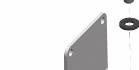
18 5.2 Sequence for mounting an SP500 positioner to a linear actuator Fig. 24 Pillar mounting kit for a linear actuator Loosely attach the magnet bracket (2) to the valve / actuator connector (refer to Figures 24 and 25). Be sure it is positioned horizontally (as shown in Figure 25). Fig. 25 Yoke mounting assembly for a linear actuator 2 18 IM-P CH Issue 3


. PN9000 PN1000 Fig.")

19 Assembled 2 Fig Slide the bracket (2) to the left or to the right (Figure 26) till the correct position is achieved. If you re using a Spirax Sarco actuator the correct position is impressed on the magnet bracket (Figure 27). PN9000 PN1000 Fig. 27 Bracket markings If you re not using a Spirax Sarco actuator, slide the bracket till the distance 'A' between the center of the magnet and the inner side of the mounting plate is 25 mm (Figure 28). Mounting plate Bracket Fig. 28 A Distance between the mounting plate and magnet Center of the magnet IM-P CH Issue 3 19

, and for the yoke")


.")
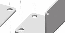
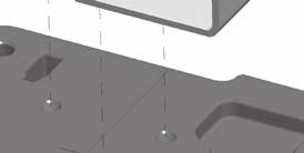
20 5.2.4 Loosely attach the positioner mounting plate to the actuator as shown in the following pictures: for the pillar actuator (Figure 29), and for the yoke actuator (Figure 30). Mounting plate Pillar actuator Assembled Fig. 29 Pillar actuator assembly Mounting plate Assembled Yoke actuator Fig. 30 Yoke actuator assembly Locate the protection plate onto the back of the SP500 positioner housing and fix in place (Figures 31 and 32). Protection plate Assembled Fig. 31 Fig IM-P CH Issue 3


 on the yoke mounted actuator (Fig.")
21 5.2.6 Attach the positioner mounting plate to the positioner as shown in Figures 33 and 34. Protection plate Adjust the vertical position of the SP500 positioner and mounting plate assembly, by sliding it up or down on the pillar style actuators, ensuring that the positioner is roughly centred on the actuator / valve stroke (Figure 30). Even if this is the ideal condition, it s not mandatory. In fact, as shown in Figure 35, the only necessary condition for correct operation is that the stroke of the magnet (dimension B) lay inside the sensor operating linear range (dimension A), i.e. the vertical dimension marked on the case of the positioner. 5 SP500 positoner A B Fig. 33 Assembled Fig. 35 Fig. 34 Attach the mounting plate When the SP500 positioner and mounting plate assembly is correctly positioned, tighten the hexagon headed screw (5) on the yoke mounted actuator (Fig. 33) to N m and tighten the 'U'bolt nuts (6) on the pillar mounted actuators (Figure 36) to N m. 6 Fig. 36 IM-P CH Issue 3 21

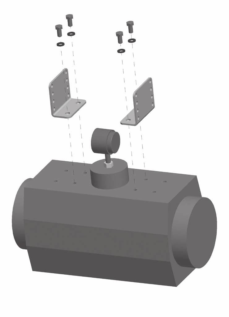
22 5.3 Sequence for mounting an SP500 positioner to a rotary actuator Assembly for fitting an SP500 on to a ¼ turn valve. Fig. 37 Mounting kit 22 IM-P CH Issue 3


23 Fig. 38 Fig. 39 Fig. 40 IM-P CH Issue 3 23


24 Fig. 41 Assembled Fig IM-P CH Issue 3
25 5.3.2 Adjust the magnet orientation as illustrated in Figures 43 and 44 and tighten the bolt to fix the magnet into position. There should be a distance of between 5 and 14 mm between the magnet and the positioner. Refer to Figure 43 for actuator with clockwise rotation. Refer to Figure 44 for actuator with anti-clockwise rotation. In fact, in this way the magnet movements will always be comprised in the sector between the directions C and D which delimit the operating area of the Hall sensor. D B A 15 C Fig. 43 View from the bottom of the positioner - Magnet orientation for clockwise actuator. B D A C Fig. 44 View from bottom of the positioner - Magnet orientation for anti-clockwise actuator. IM-P CH Issue 3 25
 and output signal to actuator (Figure 45). The supply air should be between 1.")
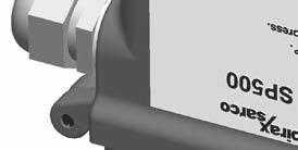
26 5.4 Air supply and connections Warning: Supply air pressure must not exceed the maximum allowable air pressure of the actuator. Air connections should be ¼" NPT for air supply (supply) and output signal to actuator (Figure 45). The supply air should be between 1.4 bar g minimum and 6 bar g maximum and be oil and dust free to IEC Mains air supply may sometimes contain traces of dirt, rust, water, oil and other deposits with the potential for contaminating the internals of the positioner. It is therefore essential that a filter / regulator is fitted in the mains air supply to the positioner. The filter / regulator should have a coalescing filter such as a Spirax Sarco type MPC2, or suitable compressed air pipework is used. ¼" NPT air signal to actuator (output 1) ¼" NPT air supply (supply) Fig IM-P CH Issue 3
27 6. Electrical connections 6.1 Guidance notes on wiring installation For heavy industrial applications it is recommended to use screened cables or signal cables run in metal conduit. Failure to do so could result in positional errors of up to ±5% in an RF field excess of 10 V/m. If screened cables are used, ensure that the screen is connected to the local earth at one end with a connection resistance of less than 1 ohm. For light industrial applications where RF fields do not exceed 3 V/m unscreened cables may be used. Cabling should be installed in accordance with BS Instrumentation in Process Control Systems: Installation design and practice or local equivalent. 6.2 Wiring diagrams Terminal block V MENU MANUAL AUTOS SET mA - + SW1 AUTOMATIC TUNE 50 % SW2 - + RTX SP500 Fig. 46 No. Pole Description V power supply option board 24 V external power supply 2 - (PWS) ma current signal input Mainboard Travel switch Retransmission and travel Travel switch switches option board (RTX) ma retransmission of valve position 10 - IM-P CH Issue 3 27
28 6.2.2 Single loop applications The SP500 is loop powered using the 4-20 ma input signal source providing a minimum signal of 3.6 ma can be maintained. Minimum current Maximum current without HART Maximum voltage drop option board with HART option board Overvoltage protection Protection against polarity inversion 3.6 ma 30 ma < 7 V < 7.4 V Up to 30 Vdc Up to 30 Vdc Fig ma signal Multi-loop applications Loop powered multi-positioner connections Fig. 48 Positioner Positioner ma signal 14 V minimum - In a loop powered application, the 4-20 ma signal must be capable of supplying a minimum of 7 V per positioner at 20 ma. In a split range application the signal source must be capable of supplying sufficient voltage, i.e. 14 V is enough to power 2 positioners. In case the SP500 smart valve positioner is equipped with the HART board the voltage drop for each positioner is 7.4 V instead of 7.0 V. 4 wires electrical connection If the controller cannot supply the voltage needed, it is possible to power one or more positioner through an external 24 V power supply connected to terminals 1 and 2. In this way the voltage drop is about 1 V per positioner with an impedance of 50 Ohm. Positioner 1 Positioner V - + Current 8 V - (1 V + 7 V) - Fig. 49 Split range with 2 positioners Please note that for this configuration the PWS option board must be fitted. The PWS option board can be specified when the product is ordered or bought later and fitted in situ - In this case reference Section 4.3 for mounting instructions. 28 IM-P CH Issue 3
29 6.2.4 Travel switchesand 4-20 ma retransmission wiring digrams 2 k 5 22 k Travel switches k 7 22 k Travel switches 2 8 Fig. 50 Software switches Example of customers external application wiring ma retransmit 10 - Fig ma retransmit Table 1 Ratings Supply Impedance On current Off current TS1 travel switch Vdc 1.8 k 13 ma 1 24 V TS2 travel switch Vdc 1.8 k 13 ma 1 24 V 4-20 ma 8-30 Vdc IM-P CH Issue 3 29
30 7. Quick start procedure port valves The following applies to positioners fitted to 2-port valves having plug above the seat and fitted to pneumatic actuators having a direct acting (DIR) 4-20 ma input signal and excludes the setting of any additional program functions (i.e. default value only). Note: For PN5100 and PN6100 series actuators an additional programming step is required. (Refer to Section 9.5.2) The positioner should be correctly assembled as described in Section 5 and Section 6 and supplied with mains air and signal pipework as described in Section Provide a minimum input signal of 3.6 ma to the positioner. SET-UP NOW should be displayed Ensure that upstream isolation valves are closed. Press and hold key for 3 seconds to advance to SP500 MENU. The display will count down the 3 seconds Press to advance to manop Press and hold key for 3 seconds to enter manual control mode MCTL In manual control press and hold or keys to drive the valve stem up or down. Check for any obstructions of valve movement. The display will indicate FILL or VENT as appropriate. Any obstruction should be investigated before proceeding to Section Press key to return to MANOP in main menu Press key to advance to AUTOS autostroke mode Press and hold key for 3 seconds to start the autostroke routine. This will take approximately 2 minutes to complete.! displayed indicates an incomplete or unsuccessful autostroke. The routine can be aborted at any time by pressing key once. If autostroke is aborted during operation ABORT will be displayed and! to indicate incomplete autostroke. On completion the program will automatically return to AUTOS in main menu. A will be displayed if successful autostroke has been completed. It is now possible to advance to RUN in main menu Press key three times to advance to RUN in main menu Press and hold key for 3 seconds to commence automatic operation. The valve will move to a control position related to the input control signal. The percentage valve travel will be displayed %. The positioner cover can now be closed and cover screws tightened. 30 IM-P CH Issue 3
31 7.2 3-port valves (with travel setting (TRAVL) 0-100%, refer to Figures 27 and 28) Proceed as above up to Section On completion of a successful autostroke press the key once to advance to SET in main menu Press key once to advance to valve type. Press key to indicate VALVE 3-PORT Press key to select VALVE 3-PORT. Continue to press key to return to SET in main menu Press key twice to advance to RUN in main menu. Proceed as described in Section IM-P CH Issue 3 31
32 8. Programming flow chart Fig. 52 SET-UP NOW Software version (Ver X.XX) SP500 MENU Mounting position check (CALIB) From RETRN (To SP500 MENU) MANOP Manual operation (MCTL) C-CAL % Travel (TRAVL 0-100% / 100-0%) AUTOS Autostroke activate (AUTOS) Note: SET, TUNE, and RUN can only be accessed on completion of a successful autostroke (AUTOS) SET Valve type (VALVE 2-PORT / VALVE 3-PORT) Actuator type (ACT) RETURN (To SP500 MENU) TUNE Dead-band (dband) Shut-off minimum (S-MIN) RUN AUTO OPERATION (% TRAVEL) Return to SP500 menu (RETRN AUTO / RETRN VENT) (RETAIN) (RESET) 32 IM-P CH Issue 3
33 Key 3 seconds enter Clear stored values (RESET) Recall stored values (RETRN) Retain temporary values (RTAIN) Enter Auto return Minimum travel (MIN-T) Maximum travel (MAX-T) Displayed % travel (DTRVL) Minimum range (MIN-R) Maximum range (MAX-R) Only if MIN-T / MAX-T not 0 / 100% Control action (CTRLA) Shut-off maximum (S-MAX) Characterisation (LIN / FAST / EQUAL) Time to open (T-UP) Time to close (T-dWN) AUTO OPERATION (ma Input signal) Stem travel (STRVL) Travel switch 2 (NC) (TS2) Travel switch 1 (NO) (TS1) Run time (RTIME) (RETAIN) (RESET) IM-P CH Issue 3 33
34 9. Programming and commissioning 9.1 Set-up now Programming notes The positioner fitted to this control valve requires programming. A minimum input signal of 3.6 ma is required to power the positioner. To program the positioner it is necessary to enter SP500 MENU and carry out an autostroke commissioning routine (AUTOS) prior to putting the control valve into automatic operation. A flow chart is included in Section 8 to guide you through the procedure. The display provides a flag indication of the active main menu function. To enter SP500 MENU press and hold key for 3 seconds. The display will count down the 3 seconds. Commissioning notes Main menu functions include: SP500 MENU View software version, mounting position check, reset default values. MANOP AUTOS SET TUNE RUN Manual control of valve movement (Actuator inflation / deflation). Automatic valve commissioning. Provides selection of % travel display. Setting of valve type, control action, travel limits and input signal span. Setting of deadband, tight shut-off, lift characterisation, travel time and software switches. Activates automatic operation plus input signal, total valve strokes and total run time. Also provides route for returning to SP500 MENU. Note: SET, TUNE and RUN functions are restricted and can only be accessed on completion of a successful autostroke routine (AUTOS). 34 IM-P CH Issue 3
35 9.2 SP500 MENU SET-UP NOW 3 seconds enter Software version (Ver X.XX) From RETRN SP500 MENU 3 seconds enter Mounting position check (CALIB) Clear stored values (RESET) Recall stored values (RETRN) Retain temporary values (RTAIN) Fig. 53 Programming notes You are now in SP500 MENU. SP500 functions include: 1. Visualisation of the embedded software version (VER--). 2. Positional setting (CALIB). 3. Resetting of programmed values to default settings (RESET). 4. To retain settings in the temporary memory (RTAIN). 5. Returning to previously stored settings (RETRN). To check the setting (CALIB) press and hold key for 3 seconds. The display will count down the 3 seconds. CALIB also provides access to RESET / RTAIN / RETRN functions. To view the embedded version of software (VER-.--) press key. To advance to manual operation (MANOP) press key VER -.-- software version Programming notes To view the version of the embedded software (VER-.--) press key. Press key to return to SP500 MENU. The display will automatically return to SP500 MENU after 10 seconds. IM-P CH Issue 3 35
36 9.2.2 CALIB - mounting position calibration Programming notes To access CALIB press and hold key for 3 seconds. The display will count down the 3 seconds. You are now in calibrate mode. The LCD shows in % the magnet position in respect to the sensor board of the positioner, without any offset or scale up or down. When the LCD shows 0% the magnet is positioned near the bottom of the positioner s case. At 50% the magnet will be in front of the cross impressed on the back of the positioner. At 100% the magnet will be roughly aligned with the top of the positioner s case. Desired setting is 50% with the valve at half stroke. The and keys can be used to manipulate the actuator inflation. In this way it is possible to check the mounting position and if necessary change it and then check again to get the positioner well centred. Press key advance to RESET / RTAIN / RETRN. 36 IM-P CH Issue 3
37 9.2.3 RETRN - RTAIN - RESET Programming notes Provides the facility to restore previous permanently stored values (RETRN), to retain values stored in the temporary memory (RTAIN) or to reset all values to factory default settings (RESET). Press and keys to select RETRN, RTAIN or RESET. To advance proceed as follows: RETRN To cancel any temporary changes to programmed values select RETRN and press key to return to SP500 MENU. RTAIN To retain temporary changes to programmed values select RTAIN and press key to return to SP500 MENU. RESET Provides the facility to reset all values to factory default settings and return to SET UP NOW. Press and hold key for 3 seconds. The display will count down the 3 seconds. Commissioning notes RETRN If changes have been made to program values they will be held in the temporary memory. To retain changes in the permanent memory it is necessary to advance to RUN in the main menu and press and hold key for 3 seconds. The display will count down the 3 seconds. If you do not wish to retain temporary changes select RETRN and press key to return to SP500 MENU. RTAIN If changes have been made to programmed values they will be held in the temporary memory. If you wish to retain these changes select RTAIN and press key to return to SP500 MENU. To retain temporary changes in the permanent memory advance to RUN in the main menu and press and hold key for 3 seconds. The display will count down the 3 seconds. RESET Resetting to default values (refer to Section 9 for default values) should be used if it is intended to use the positioner on a different control valve. If the SP500 positioner has been moved on its mounting or is to be fitted on a different control valve it will be necessary to undertake a new autostroke (AUTOS). RESET to factory default settings can also be used if it is required to recommission the valve. To reset to factory default values select RESET and press and hold The display will count down the 3 seconds. key for 3 seconds. IM-P CH Issue 3 37
38 9.3 MANOP MANOP 3 second enter Manual operation (MCTL) C-CAL Fig. 54 Programming notes Press and hold key for 3 seconds to enter manual control mode (MCTL). The display will count down the 3 seconds. Press the key to enter the current calibration mode (C-CAL). Press to return to MANOP. In MANOP press key to advance to autostroke (AUTOS). Commissioning notes Before initiating an autostroke commissioning (AUTOS) use manual control (MCTL) to manually fully inflate and deflate the actuator to ensure there are no obstructions to the full valve travel movement. Manual control is also useful during normal operation to manually control the valve position as a commissioning aid or in the event of input signal failure MCTL - manual control Programming notes Manual control enables the actuator to be manually inflated or deflated. Press key to inflate actuator and key to deflate the actuator. Press and hold or key to accelerate action. Prior to undertaking an AUTOS the display will indicate FILL or VENT. On completion of AUTOS the display will indicate % valve travel. Manual control (MCTRL) - Tight shut-off function Press and hold the key to drive the valve to its closed position. At 0% travel the! will flash to indicate limit of travel. To initiate tight shut-off release the key and press again. The actuator will be vented of air to provide dead tight shut-off. This also applies to the 100% valve position by pressing and releasing the key and pressing again to inflate the actuator to provide dead tight shut-off. Manual control (MCTRL) - Travel limits When operating in manual control any travel limit settings will be overridden therefore it is possible to manual position the valve through its full 0 to 100% travel as measured in autostroke (AUTOS). Commissioning notes Before initiating an autostroke commissioning routine (AUTOS) the actuator should be manually fully inflated and deflated to ensure there are no obstructions to the full valve travel movement. Manual control is also useful during normal operation to manually control the valve position as a commissioning aid or in the event of input signal failure. 38 IM-P CH Issue 3
39 9.3.2 C-CAL - current calibration Programming notes C-Cal provides a simple way to make a fine calibration of the input current signal (4-20 ma). To perform the calibration: 1. Enter C-CAL and press the key, then press the key. 2. Generate a 4 ma input signal and press 3. Generate a 12 ma input signal and press 4. Generate a 20 ma input signal and press If 'ERROR' is displayed the calibration routine is aborted. The value of the generated signal is too far from the expected one. Be sure that a 4 ma, 12 ma or 20 ma signal is generated as required. Press to return to C-CAL. If 'OK' is displayed the calibration has succeeded. Press to return to C-CAL. Where possible current calibration should be overtaken, to guarantee a perfect match between the input current generated and the reading of the SP500. Let s assume that the table below show the input signal generated by a PLC or DCS versus the input signal read by the SP500. Setpoint Input current from PLC Current read from SP500 0% 3.6 ma 3.8 ma 50% 12 ma 12.2 ma 100% 20 ma 20.2 ma Hence when the setpoint is 0% the PLC generates a 3.6 ma instead of 4 ma. After C-CAL is executed the SP500 recalibrates the current read to compensate the error. Setpoint Input current from PLC Current read from SP500 0% 3.6 ma 4 ma 50% 12 ma 12 ma 100% 20 ma 20 ma In this way a perfect match is achieved between the setpoint of the PLC and the setpoint of the of the SP500 (i.e. the input current read by the SP500). IM-P CH Issue 3 39
40 9.4 AUTOS - automatic autostroke commissioning % Travel (TRAVL 0-100% / 100-0%) AUTOS 3 second enter Autostroke activate (AUTOS) Fig. 55 Programming notes AUTOS provides access to: 1. Autostroke commissioning (AUTOS). 2. % travel display (TRAVL). AUTOS Autostroke provides an automatic commissioning routine which will take approximately 1 to 3 minutes to complete. Press and hold key for 3 seconds to start autostroke. The display will count down the 3 seconds. When autostroke is active a flashing AUTOS message will be displayed. On completion of a successful autostroke the programme will automatically return to AUTOS in the main menu and a will be displayed. In the event of an unsuccessful autostroke routine a flashing! will be displayed. If during AUTOS inconsistent data is obtained due to mechanical problems, the autostroke procedure will be terminated and ABORT will be displayed. It is also possible to immediately abort during an autostroke routine by pressing the key. ABORT will be displayed together with a flashing!. Error messages: ERROR 1 Indicates a wrong mechanical coupling between positioner and actuator. Check the mounting is correct. ERROR 2 Indicates that there is insufficient air pressure to achieve valve movement. Check that the air supply is adequate to overcome the actuator spring force. Fitting of a gauge block will aid the commissioning procedure. ERROR 3 Indicates that the actuator will not deflate. Check that there is no obstruction preventing the stem travel or air venting from the actuator. Error 4 indicates that the stroke measured is less than the minimum stroke allowed - 10 mm for linear valves, and 5 for quarter turn valves (output 1 and output 2 for double action applications). ABORT indicates mechanical problems have occurred during the Autostroke procedure or the key has been pressed during Autostroke to abort the procedure. On completion of a successful autostroke it will be possible to advance to SET, TUNE and RUN functions in the main menu. Press the key to advance to these functions. Commissioning notes Prior to undertaking an autostroke routine, manual operation should be used to fully inflate and deflate the actuator to ensure there are no obstructions to the full valve movement. Autostroke is an automatic commissioning routine that checks for maximum valve travel, signal response, valve characteristics, inflation / deflation times etc. Data gathered will be automatically download into the embedded software to ensure optimum performance of the valve / actuator combination. Autostroke commissioning will take approximately 1 to 3 minutes to complete depending on air pressure and actuator size etc. Autostroke commissioning must be carried out on start-up or at any other time if the valve performance is not satisfactory. 40 IM-P CH Issue 3
41 9.4.1 TRAVL - % travel display Programming notes Press key to access TRAVL. Provides selection of % valve travel display with option of 0-100% or 100-0%. Default is 0-100%. Use and keys to toggle selection. Press key to return to AUTOS. Commissioning notes The selection of % valve travel display depends on the valve and actuator configuration. Figures 56 to 59 (pages 41 and 42), and Figures 60 and 61 (page 43) provide guidance on selection. After completion of AUTOS if a change is made to TRAVL it will be necessary to initiate an AUTOS routine once again. Display = 0% Display = 100% Fig port valve normally closed - TRAVL setting = 0 to 100% Display = 0% Display = 100% Fig port valve normally open - TRAVL setting = 0 to 100% IM-P CH Issue 3 41
42 Display = 100% Display = 0% Fig port valve normally open - TRAVL setting = 100% to 0% Display = 100% Display = 0% Fig port valve normally closed - TRAVL setting = 100% to 0% 42 IM-P CH Issue 3
43 100% 0% TRAVEL setting = 0 to 100% DISPLAY = 0% TRAVL setting = 100 to 0% DISPLAY = 100% TRAVEL setting = 0 to 100% DISPLAY = 100% TRAVL setting = 100 to 0% DISPLAY = 0% 100% 0% Fig port valve and spring extend actuator 100% 0% TRAVEL setting = 0 to 100% DISPLAY = 0% TRAVL setting = 100 to 0% DISPLAY = 100% TRAVEL setting = 0 to 100% DISPLAY = 100% TRAVL setting = 100 to 0% DISPLAY = 0% 100% 0% Fig port valve and spring retract actuator IM-P CH Issue 3 43
44 9.5 SET - setting of valve functions SET Valve type (VALVE 2-PORT / VALVE 3-PORT) Actuator type (ACT) Maximum range (MAX-R) Control action (CTRLA) Minimum range (MIN-R) Minimum travel (MIN-T) Displayed % travel (DTRVL) Maximum travel (MAX-T) Fig. 62 Only if MIN-T / MAX-T not 0 / 100% Programming notes Provides access to basic valve set up functions. Press SET functions. key to scroll round all Functions include: - Valve type (2-port or 3-port) (VALVE) - Actuator type (on/ off) (ACT) - Control action (direct or reverse) (CTRLA) - Minimum travel setting (0 to 66.66%) (MIN-T) - Maximum travel setting (33.3 to 100%) (MAX T) - Displayed % travel (on/ off) (DTRVL) - Minimum span range (input ma signal) (MIN-R) - Maximum span range (input ma signal) (MAX-R) Press key to advance to valve type (VALVE). Repeat pressing of key will scroll round all SET functions. Press key to advance to TUNE in the main menu. Commissioning notes Each SET function has a default value as listed in the Installation and Maintenance Instructions. Default values are based on a 2-port normally closed valve having maximum 95% lift and an input signal span range 4-20 ma. SET values should be adjusted to suit the valve type (2-port or 3-port) and application. Functions include the facility to change the control action, limit the full travel of the valve plug (minimum and maximum) and to split range the input signal. More detailed information is provided for each SET function. 44 IM-P CH Issue 3
45 9.5.1 VALVE - valve type Programming notes Provides selection between 2-port and 3-port valves. Default is 2-port valve. Default values for travel limit settings (MIN-T and MAX-T) and early vent / inflate settings (S-MIN and S-MAX) will depend on the valve type (2-port or 3-port) and control action (direct or reverse) as follows: Valve type 2-port 3-port Display Direct Reverse Direct Reverse MIN-T 0% 0% 0% 0% MAX-T 95% 95% % S-MIN 0.1% OFF 0.1% 0.1% S-MAX OFF 0.1% 0.1% 0.1% Use and keys to select type. Press key to accept displayed type and advance to actuator type (ACT). Commissioning notes Selection of 2-port or 3-port valves will automatically alter the maximum travel default value (MAX-T) to 95% for 2-port and 100% for 3-port valves. Advance to MAX-T to change these values if required ACT - actuator type Programming notes ACT selection makes the positioner control more fluid and reactive, improving feedback to the control signal. Selection is: 'ON' or 'OFF'. Default value is 'OFF'. Use the and keys to toggle selection. Press key to accept displayed value and advance to Control action (CTRLA). Commissioning notes If the actuator or the valve have high hysteresis or high friction it is suggested to set ACT to 'OFF'. If hunting is present set ACT to 'OFF'. IM-P CH Issue 3 45
46 9.5.3 CTRLA - direct or reverse control action Programming notes Provides selection of direct (dirct) (4-20 ma) or reversed (REV) (20-4 ma) valve positioning control action. Press and keys to select desired action. Default action is dirct. Default values for travel limit settings (MIN-T and MAX-T) and early shut-off vent / inflate settings (S-MIN and S-MAX) will depend on the valve type (2-port or 3-port) and control action (direct or reverse) as follows: DIR - direct action Display 2-port 3-port MIN-T 0% 0% MAX-T 95% 100% S-MIN 0.1% 0.1% S-MAX OFF 0.1% REV - reverse action Display 2-port 3-port MIN-T 0% 0% MAX-T 95% 100% S-MIN OFF 0.1% S-MAX 0.1% 0.1% Press key to accept the displayed action and advance to minimum travel setting (MIN T). Commissioning notes Selection of direct or reverse action changes the direct of valve plug movement relative to the input signal. Refer to Figures 63 and 64, and the table shown in Figure 65 for further guidance. Valve plug position Valve stem lifting Valve plug position Valve stem falling ma Increasing input signal ma Increasing input signal Fig. 63 Direct action (DIR) Fig. 64 Reverse action (REV) 46 IM-P CH Issue 3
47 Fig. 65 CTRL Control Action dirct or REV setting guidance Installed orientation At-rest position Control action 100% dirct 0% 4 ma 20 ma 100% 0% REV 100% 0% 0% 4 ma 20 ma 100% dirct 0% 4 ma 20 ma 100% (TRAVL) 0-100% 100% 0% REV 4 ma 20 ma 100% 4 ma 20 ma dirct 0% 100% 4 ma 20 ma 0% 100% 0% 0% 100% REV 4 ma 20 ma dirct 0% (TRAVL) 100-0% Manual Selection of required % travel (TRAVL) 100% Automatic determintation Spring action only affects the rest or fail-safe position 100% 0% 4 ma 20 ma REV Manual Selection of required Control Action (CTRLA) IM-P CH Issue 3 47
48 9.5.4 MIN-T - minimum travel setting Programming notes Enables the minimum valve travel to be set as a percentage of the maximum travel obtained during autostroke. Maximum setting is MAX-T less 33.3%. Default value is 0%. Use and keys to alter the displayed value. Press key to accept the displayed value and advance to the maximum travel setting (MAX-T). Commissioning notes Minimum travel should be used where a minimum flowrate is required to be maintained through the valve, (i.e. a cooling water application). Setting a minimum travel % value will prevent the valve fully closing. The input signal span range set (MIN-R) and (MAX-R) will operate over the travel limits set. If a value for MIN T is set it will exclude the setting of shut-off minimum (S-MIN) for control action direct (DIR) and shut-off maximum (S-MAX) for control action reverse (REV) MAX-T - maximum travel setting Programming notes Enables the maximum valve travel to be set as a percentage of the maximum travel measured during autostroke. Minimum setting is MIN-T plus 33.3%. Default values will depend on the selection of valve type (2-port or 3-port) and control action (direct or reverse) as follows: Valve type Direct Reverse 2-port 95% 95% 3-port 100% 100% Use and keys to adjust the displayed value. Press key to accept displayed value and advance to the next function. Commissioning notes The maximum valve travel percentage should be used to prevent a control valve fully opening. This is useful for applications where the valve is oversized or to restrict the maximum flowrate through the valve. On 2-port valves the default value is 95% to prevent the back of the plug hitting the bonnet. On 3-port valves to ensure shut-off on both seats a 100% setting is required. The input signal span range set (MIN-R) and (MAX-R) will operate over the travel limits set. If a value for MAX-T is set it will exclude the setting of shut-off maximum (S-MAX) for direct action (DIR) and shut-off minimum control action (S-MIN) for reverse action (REV). 48 IM-P CH Issue 3
49 9.5.6 DTRVL - displayed travel percentage Programming notes The full mechanical limits of valve travel (0 to 100%) are measured during autostroke (AUTOS). It is possible to limit the minimum and maximum valve travel by programming MIN-T and MAX-T values, i.e. MAX-T maximum travel limit of 95% (Autostroke default value for 2-port valves). DTRVL (0 to 100% displayed travel value) can be displayed over the actual mechanical travel limits (as measured during Autostroke), or adjusted MIN-T and MAX-T travel settings. DTRVL programming options DTRVL - ON will display 0 to 100% over the MIN-T and MAX-T travel settings, or, DTRVL - OFF will display 0 to 100% over the actual mechanical limits of travel. Default value is DTRVL - ON. Use and keys to toggle selection. Press key to accept displayed 'ON' or 'OFF' option and advance to minimum range setting (MIN-R). Examples Example 1 Example 2 MAX-T = 95% MAX-T = 95% MIN-T = 0% MIN-T = 5% Display values DTRVL - ON DTRVL - OFF 100% 95% 0% 0% Display values DTRVL - ON DTRVL - OFF 100% 95% 0% 5% Commissioning notes DTRVL provides the choice of travel display. For 2-port valves you can adjust the MAX-T setting to achieve the actual desired valve lift (i.e. 20 mm or 30 mm, etc). Using DTRVL you can then choose to display the MAX-T valve travel you have set as 100%. IM-P CH Issue 3 49
50 9.5.7 MIN-R - minimum signal span range Programming notes Enables the minimum ma input signal span range to be set. The value set will correspond to the minimum travel setting. Default value is 4 ma. Use and keys to alter the displayed value. Minimum difference between MIN-R and MAX-R is 4 ma. Press key to accept the displayed value and advance to the maximum ma input span range (MAX-R). Commissioning notes This function can be used to set split range applications i.e ma or ma. To ensure tight shut-off refer to Section S-MIN, page MAX-R - maximum signal span range Programming notes Enables the maximum ma input signal span range to be set. The value set will correspond to the maximum travel setting. Default value is 20 ma. Use and keys to alter the displayed value. Minimum difference between MIN-R and MAX-R is 4 ma. Press key to accept the displayed value and return to SET in the main menu. Commissioning notes This function can be used to easily set split range applications i.e ma or ma. To ensure tight shut-off refer to Section S-MAX, page IM-P CH Issue 3
51 9.6 TUNE - setting of valve tune functions TUNE Dead-band (dband) Shut-off minimum (S-MIN) Travel switch 2 (TS2) Normally closed Shut-off maximum (S-MAX) Travel switch 1 (TS1) Normally open Characterisation (LIN / FAST / EQUAL) Time to close (T-dWN) Time to open (T-UP) Fig. 66 Provides access to more advanced valve tuning functions including: - Dead-band (valve positioning sensitivity) (dband) - Shut-off minimum (ensures tight closure) (S-MIN) - Shut-off maximum (ensures tight closure) (S-MAX) - Characterisation (signal / lift relationship) (CHAR) - Time open (slows down valve opening) (T-UP) - Time close (slows down valve closure) (T-dWN) - Travel switch 1 normally open (sets software travel switch) (TS1) - Travel switch 2 normally closed (sets software travel switch) (TS2) Programming notes Press key to advance to deadband (dband). Repeated pressing of key will scroll round all TUNE functions. If you do not wish to alter TUNE default values press key to advance to RUN in the main menu. Commissioning notes Each TUNE function has a default value as listed in the Installation and Maintenance Instructions. Default values are based on a 2-port normally closed valve having maximum 95% lift and an input signal span range 4-20 ma. TUNE values should be adjusted to suit the valve type and application. Functions include: 1. The facility to alter deadband positioning sensitivity (to dampen out signal fluctuations). 2. Setting input signal to achieve tight shut-off (inflation and deflation of actuator). 3. Relationship between valve lift to input signal. 4. Slowing down the valve open or closing time duration. 5. Setting the switching position for the software travel switches. More detailed information is provided for each TUNE function. IM-P CH Issue 3 51
52 9.6.1 dband - deadband setting (positional sensitivity) Programming notes Dead-band provides adjustment of the valve positioning sensitivity relative to the input signal and is expressed as a % of the input signal span. Default value based on a 4-20 ma input signal span is 0.5% with a minimum setting of 0.2%. Note: 3% may be displayed if ACT is set to 'ON'. Refer to Section 9.5.2, page 45. These values may change if the input signal span is reduced i.e. for a 4 ma input signal span the default and minimum setting is 0.8%. The maximum setting is 10% of the input signal span. To alter the displayed value press and keys. Press key to accept the displayed value and advance to the shut-off minimum (S-MIN). Commissioning notes Setting a narrow deadband may induce oscillations of valve movement caused by fluctuations in the input signal, high stem friction or operating at low ambient temperatures below 0 C. Setting a wider deadband will dampen out oscillations but may cause an inaccuracy in actual valve position. This effect will increase if valve travel is limited. It is normally recommended that the default value is used. If necessary gradually increase the % value to dampen out any oscillations in valve movement. This may be necessary for valves having graphite packed stem seals or smaller size actuators where typically a deadband of 4% may be required S-MIN - valve shut-off - minimum travel Programming notes Provides the facility to fully vent the actuator at a predetermined input signal. The value set is a percentage of the input signal span range, i.e. setting a value of 10% with an input span range of 4-20 ma (span 16 ma), will cause the valve to close with an input signal of 5.6 ma i.e. 4 ma ma (10% of 16 ma). Maximum setting is 20%. Default values will depend on the selection of valve type (2-port or 3-port) and control action (direct or reverse) as follows: Valve type Direct Reverse 2-port 0.1% Off% 3-port 0.1% 0.1% For direct control action (dirct) can only be set if MIN-T = 0% (will vent the actuator at set value). For reverse action (REV) can only be set if MAX-T = 100% (will inflate the actuator at set value). Press and keys to alter the displayed value. Press key to accept the displayed value and advance to shut-off maximum (S-MAX). Commissioning notes With an actual input signal equivalent to minimum input signal span range (MIN-R) it may cause the valve plug to hover over the seat preventing tight closure with the possibility of erosion damage to the plug and seat faces. Setting a shut-off value can help prevent this by providing early closure of the valve. 52 IM-P CH Issue 3
53 9.6.3 S-MAX - valve shut-off maximum Programming notes Provides the facility to fully inflate the actuator at a pre-determined input signal. The value set is a percentage of the input signal span range, i.e. setting a value of 10% with an input span range of 4-20 ma (16 ma), will cause the valve to close with an input signal of 18.4 ma i.e. 20 ma ma (10% of 16 ma). Maximum setting is 20%. Default values will depend on the selection of valve type (2-port or 3-port) and control action (direct or reverse) as follows: Valve type Direct Reverse 2-port Off 0.1% 3-port 0.1% 0.1% For direct action (dirct) can only be set if MAX-T = 100% (will inflate the actuator at set value). For reverse action (REV) can only be set if MIN-T = 0% (will vent the actuator at set value). Press and keys to alter displayed value. Press key to accept the displayed value and advance to the characterisation (CHAR). Commissioning notes With an actual input signal of 20 ma and a maximum span range setting (MAX-R) of 20 ma may cause the valve plug to hover over the seat preventing tight closure with the possibility of erosion damage to the plug and seat. Setting a shut-off value can help prevent this by providing early closure of the valve CHAR - valve characterisation Programming notes Provides selection of linear (LIN), equal percentage (EQUAL) or fast opening (FAST) characterisation. Characterisation is the relationship between input signal and valve lift. Default value is Linear (LIN). Use and keys to select the desired action. Press key to accept the displayed characterisation and advance to time open (T-UP). Commissioning notes The standard characterisation for 2-port and 3-port valves is linear (LIN). For special applications using 2-port valves an equal percentage (EQUAL) or fast opening (FAST) characteristic can be selected. With equal percentage the valve will start to open slowly and gradually accelerate opening related to input signal. With fast opening characteristic the valve will commence to open quickly and gradually slow down opening related to the input signal. This action is in addition to the valve trim flow characterisation (refer to Figure 67 for guidance). Ratio 1:1 Ratio 1:50 Ratio 50:1 Valve lift Linear Valve lift Equal percentage Valve lift Fast opening Fig. 67 Signal (ma) Signal (ma) Signal (ma) IM-P CH Issue 3 53
54 9.6.5 T-UP - valve slow opening action Programming notes This function slows down the time taken for the valve to travel from 0 to 100% lift. The time displayed is the fastest travel time measured during autostroke (AUTOS). 4 seconds may be displayed if ACT is set to 'ON' (refer to Section 9.5.2, page 45). Default value is the fastest time measured during autostroke. Press and keys to alter the displayed value. Press key to accept the displayed value and advance to time down (T-dWN). Commissioning notes The time displayed on start-up is the fastest time measured during autostroke commissioning (AUTOS). A time cannot be set less than the minimum recorded during autostroke. The value set will be the time taken for the valve to travel from 0 to 100% lift. The time set will apply at all times and not just at start-up. This function is useful to prevent the effects of system waterhammer, thermal shocks or slow down over-reactive systems or the effects of oversized valves. Default is the fastest time measured during autostroke. Maximum setting is 180 seconds T-dWN - valve slow closing action Programming notes This function slows down the time taken for the valve to travel from 100 to 0% lift. The time displayed on start-up is the fastest travel time measured during autostroke (AUTOS). 4 seconds may be displayed if ACT is set to 'ON' (refer to Section 9.5.2, page 45). Default value is the fastest time measured during autostroke. Press and keys to alter the displayed value. Press key to accept the displayed value and advance to travel switch 1 (TS1). Commissioning notes During autostroke routine the quickest time taken for the valve to fully close will be measured and displayed. A time cannot be set less than the minimum recorded during autostroke. The value set will be the time taken for the valve to travel from 100 to 0% lift. This action will apply at all times and not just at start-up. This function is useful to prevent the effects of system waterhammer, or to slow down over-reactive systems or the effects of oversized valves. Default is the minimum time measured during autostroke. Maximum setting is 180 seconds. 54 IM-P CH Issue 3
55 9.6.7 TS1 and TS2 software travel switches Two switches are available TS1 and TS2. TS1 is normally open and TS2 is normally closed. Switching action is set as a % of valve travel (refer to Figures 68 and 69). TS1 - software configured travel switch 1 (normally open) Programming notes The switching point can be set as a percentage of the valve travel between 0 to100%. A value can be set outside the limits of the travel settings (MIN-T) and (MAX-T). Initially OFF will be displayed indicating that the switch is not set. To set a switching point press and keys to alter the displayed value. Press key to accept the displayed value and advance to travel switch 2 normally closed (TS2). Commissioning notes Travel switch 1 (TS1) is normally open. External wiring should be made between terminals 1 (+) and 2 (-). The value set is a % of valve travel. At the set value the switch will close. The status of the switch will be shown on the LCD (refer to Figure 68). Software configured travel switches can be used to remotely indicate valve position or to operate warning devices, fans, stirrers, motors or other process equipment via a secondary switching device. Switch closed Switch open Travel 100% 50% 0% Note: Software configured travel switches can be set within the range 0% to 100% of full travel irrespective of any travel limit settings. Signal Fig. 68 TS1 Travel switch 1 (normally open) IM-P CH Issue 3 55
56 TS2 - software configured travel switch 2 (normally closed) Programming notes The switching point can be set as a percentage of the valve travel between 0 to 100%. A value can be set outside the limits of the travel settings (MIN-T) and (MAX-T). Initially OFF will be displayed indicating that the switch is not set. To set a switching point press and keys to alter the displayed value. Press key to accept the displayed value and return to TUNE in the main menu. Commissioning notes Travel switch 2 (TS2) is normally closed. External wiring should be made between terminals 3 (+) and 4 (-). The value set is a % of valve travel. At the set value the switch will open. The status of the switch will be shown on the LCD (refer to Figure 69). Software configured travel switches can be used to remotely indicate valve position or to operate warning devices, fans, stirrers, motors or other process equipment via a secondary switching device. Note: If the switch is in its 'off' status it will be an open circuit. Switch open Switch closed Travel 100% 50% 0% Note: Software configured travel switches can be set within the range 0% to 100% of full travel irrespective of any travel limit settings. Signal Fig. 69 TS2 Travel switch 2 (normally closed) 56 IM-P CH Issue 3
57 9.7 RUN - automatic operation RUN AUTO OPERATION (% TRAVEL) ma (ma input signal) Return to SP500 MENU Return to SP500 menu (RETRN AUTO / RETRN VENT) (RETAIN) (RESET) Run time (RTIME) Stem travel (STRVL) (RETAIN) (RESET) Fig. 70 Programming notes Provides the facility to put the valve into automatic operation. Press and hold key for 3 seconds to start automatic operation. The display will count down the 3 seconds. The valve will move to a position in response to the input control signal. All values stored in the temporary memory will be transferred to the permanent memory. Commissioning notes By pressing and holding the key for 3 seconds all values previously set will be entered into the permanent memory. The valve will move to a position as dictated by the input control signal. To alter or check SET or TUNE values it is necessary to return to SP500 MENU. Press and hold key for 3 seconds to return to SP500 MENU. The display will count down the 3 seconds. There are two options for returning to SP500 MENU: Option 1 is to stay in automatic control (AUTO) where the valve will continue to position itself relative to the input control signal. Option 2 is to vent the actuator (VENT) where the valve will travel to its fail-safe position. IM-P CH Issue 3 57
58 9.7.1 Automatic operation - % travel Programming notes During normal automatic operation the % valve travel will be continuously displayed together with the switch status of the software travel switches (if fitted). Additionally, a will be displayed indicating that the valve is operating satisfactorily. At any time during automatic operation the ma input signal can be displayed by pressing key. To return to SP500 MENU press and hold key for 3 seconds. The display will count down the 3 seconds. You will advance to RETRN with the option of AUTO (automatic operation) or VENT (venting air from actuator). Use and keys to select the desired option. Press key to accept the displayed option and return to SP500 MENU. Commissioning notes During normal operation the % valve travel will be continually displayed. A indicates that the valve is performing satisfactorily. Causes of fluctuations in valve movement can be related to input signal. Press key to view actual ma input signal Input signal - ma signal display Programming notes The ma input signal will be displayed. Press key to return to displaying % travel. The programme will automatically return to displaying % travel after 5 minutes. It is possible to advance to view valve diagnostics data STRVL (total valve strokes) and RTIME (total run time). To advance to STRVL press and hold key for 3 seconds. The display will count the 3 seconds. Commissioning notes This function is of assistance to visualise and check input signal relative to valve position and to investigate causes of fluctuations in valve movement. The ma input signal will be displayed for 5 minutes. Press key to return to displaying % travel. The programme will automatically return to displaying % travel after 5 minutes. 58 IM-P CH Issue 3
59 9.8 STRVL and RTIME - valve diagnostics Provides visibility of total number of valve strokes (STRVL) and total valve run time in hours (RTIME) STRVL - total stem travel Programming notes The number displayed should be multiplied by a factor of 10 to obtain the total number of complete valve strokes. A complete valve stroke is as measured in autostroke AUTOS. The number displayed can be retained (RTAIN) or reset to zero (RESET). Press the key to advance to RTAIN / RESET. Press and keys to toggle selection. Press key to accept the displayed selection and advance to run time RTIME. Commissioning notes Information displayed should be used in conjunction with total runtime RTIME to assess the valve usage and evaluate the need for routine maintenance, replacement of stem seals etc. The number displayed should be multiplyed by a factor of 10 to obtain the local total number of complete valve strokes. (A complete valve stroke is as measured in autostroke (AUTOS)). The maximum possible display value is If this value is exceeded, the display will roll over to zero and an! will be displayed. To retain the displayed value press the enter key and select RTAIN. If the valve is dismantled for maintenance inspection etc. The value can be reset if required by selecting RESET RTIME - total valve run time in hours Programming notes The number displayed is the total valve run time in hours. Run time is defined as the total time the positioner is receiving a control signal. The number displayed can be retained (RTAIN) or reset to zero (RESET). Press the key to advance to RTAIN / RESET. Press and keys to toggle selection. Press key to accept the displayed selection and return to displaying % travel. Commissioning notes Information displayed should be used in conjunction with total valve strokes (STRVL) to assess the valve usage and evaluate the need for routine maintenance, replacement of stem seals etc. To retain the displayed value press key and select RTAIN. If the valve is dismantled for maintenance inspection etc. The value can be reset to zero if required by selecting RESET. IM-P CH Issue 3 59
60 9.9 RETRN - return to SP500 MENU in main menu Return to SP500 MENU Fig. 71 Return to SP500 menu (RETRN AUTO / RETRN VENT) AUTO OPERATION (% TRAVEL) Programming notes Press and hold key for 3 seconds. The display will count down the 3 seconds. This provides the facility to return to SP500 MENU with the option of staying in automatic operation (AUTO) or venting the actuator (VENT). Use and keys to toggle selection. Press key to select and return to SP500 MENU. Commissioning notes To alter any SET or TUNE values, go into manual control (MCTL) it is then necessary to return to the SP500 MENU. Any values altered will be recorded in the temporary memory and activated immediately. To store in the permanent memory it will be necessary to advance to RUN and press and hold key for 3 seconds. The display will count down the 3 seconds. To return to the main menu but stay in automatic control select AUTO. The valve will continue in automatic operation and respond to changes in input control signal. With the exception of CALIB and MCTL functions, main menu and subroutines will timeout after 5 minutes if no key is pressed and revert to displaying % TRAVEL in automatic control mode. Any temporary changes made will not be recorded in the permanent memory. To return to main menu in a fail-safe position select VENT. The actuator will be fully vented of air and the valve will return to its fail-safe position. To return to manual control (MCTL) advance to MANOP in the main menu and advance to manual control (MCTL). The valve can now be manually controlled using the and keys to inflate or deflate the actuator. The desired % TRAVEL will be displayed. To return to automatic control advance to RUN and press key for 3 seconds. The display will count down the 3 seconds. The valve will revert to automatic control and position itself relative to the input control signal. Any SET or TUNE values altered will be recorded in the permanent memory. 60 IM-P CH Issue 3

61 10. Maintenance 10.1 Air supply quality As stated in Section 5.4, it is important for correct operation of the SP500 positioner that good quality air is supplied. It is therefore recommended that a Spirax Sarco MPC2 filter regulator or equivalent is fitted on the air supply to the positioner. In addition the SP500 positioner has an internal filter. In normal operation it is recommended that this filter is replaced every 6 to 12 months depending on the air quality and valve usage. A spare filter plug kit can be obtained from Spirax Sarco that includes: filter plug, plus 3 off 'O' rings and filter Fitting replacement filter plug kit To change the filter proceed as follows: - Ensure that the air supply to the positioner is isolated. - Unscrew the filter plug (1) from the SP500 housing using a 5 mm hex. head socket key (refer to Figure 72). The replacement filter plug can now be fitted: - Fit the 'O' ring (4) and filter (3) onto the filter plug (1) (refer to Figure 56). - Finally fit the retaining screw (2). The filter plug can now be replaced into the SP500 housing, checking that the 'O' ring (4) is correctly located. The pnuematic air supply can now be restored to the positioner and checks made to ensure that the filter plug 'O' ring has provided the neccesary air tight seal. Fig. 72 Filter plug (1) 2 3 Fig IM-P CH Issue 3 61
SP2 Electropneumatic Smart Positioner
 3439150/5 IM-P343-19 CH Issue 5 SP2 Electropneumatic Smart Positioner Installation and Maintenance Instructions 1. Index 2. Safety information 3. Technical information 4. Options 5. Installation 6. Electrical
SP2 Options Installation and Maintenance Instructions
 3439152/2 IM-P343-22 CH Issue 2 SP2 Options Installation and Maintenance Instructions 50% SP2 1 2 3 4 5 General safety information Options Electrical connections Programming and commissioning travel switches
Fig Single-Acting Rotary Smart Positioner
 Fig. 3303 Single-Acting Rotary Smart Positioner Order Information Model No. EC03303RSN52000S Econ series 3300 Smart Positioner for quarter turn actuators in single acting version. This positioner regulates
Series A Electric Linear Actuators
 3581650/3 IM-P358-11 CH Issue 3 Series A Electric Linear Actuators Installation and Maintenance Instructions 1. Safety information 2. General product information 3. Installation 4. Commissioning 5. Maintenance
SS3 Linear / Rotary. Smart Valve Positioner. Smart performance with innovative and ever-strong coil drive even under harsh working environments
 Smart Valve Positioner SS3 Linear / Rotary Smart performance with innovative and ever-strong coil drive even under harsh working environments Easy and quick auto-calibration Detecting RA (reverse acting)
SMART VALVE POSITIONER 4 to 20 ma + HART Digital Communication. smar B87
 SMART VALVE POSITIONER to ma + HART Digital Communication B87 DESCRIPTION The FY microprocessor based positioner provides fast and accurate positioning of diaphragm or cylinder actuators. The FY produces
EL5600 Series Electric Linear Actuators Installation and Maintenance Instructions
 3581050/5 IM-P358-05 CH Issue 5 EL5600 Series Electric Linear Actuators Installation and Maintenance Instructions 1 Safety information 2 General 3 Installation 4 Commissioning 5 Maintenance IM-P358-05
EL7000 Series Electric Linear Actuators
 3582050/4 IM-P358-15 CH Issue 4 EL7000 Series Electric Linear Actuators Installation and Maintenance Instructions EL7200 1. Safety information 2. General product information 3. Installation and Commissioning
Signet Pressure Transmitter
 Signet 80 Pressure 80.090 80.090 Rev. J 0/ English CAUTION! Remove power to unit before wiring input and output connections. Follow instructions carefully to avoid personal injury. Contents. Installation.
Signet Pressure Transmitter
 Signet 8450 Pressure English 8450.090 8450.090 Rev. G /06 English CAUTION! Remove power to unit before wiring input and output connections. Follow instructions carefully to avoid personal injury. Contents
Series 3730 Electropneumatic Positioner Type
 Series 3730 Electropneumatic Positioner Type 3730-1 Application Single-acting or double-acting positioner for attachment to pneumatic control valves. Self-calibrating, automatic adaptation to valve and
Installation and Operating Instructions Electro-Pneumatic Rotary Positioner SP-21. Description of Device. Part Number System
 Description of Device VALMAC Posi-Zest SP-2100 Series is the advanced control device for a rotary control valve that provides unparalleled stability in difficult environments. Easy Maintenance Precise
Instruction and Operating Manual
 M/SS2/E 01 2011 Instruction and Operating Manual Smart Valve Positioner SS2L / SS2R Series Contents 1. Introduction 2 11.5 Sub-Parameters Flow Diagram 2. Overview of Structure 3 11.5.1 Change of Input
The AEL6 series smart electric actuator
 controls and instrumentation solutions The AEL6 series smart electric actuator A E L 6 AEL6 series Our newly launched smart electric actuator The AEL6 series of smart electric linear actuators are suitable
Signet Temperature Transmitter
 Signet 80 Temperature English 80.090 80.090 Rev. G /0 English CAUTION! Remove power to unit before wiring input and output connections. Follow instructions carefully to avoid personal injury. Contents.
SP1 Smart Positioner Installation and Maintenance Instructions
 3439050/1 IM-P343-09 CH Issue 1 SP1 Smart Positioner Installation and Maintenance Instructions Operating elements Safety instructions Operating instructions in brief 1.Technical description 2. Mounting
Moniteur INSTALLATION & OPERATING INSTRUCTIONS. SERIES 40 Positioners. Installation and Operating Instructions Series 40 Positioners.
 INSTALLATION & OPERATING INSTRUCTIONS SERIES 40 Positioners Form IO2-0406 Description of Device Moniteur's Series 40 pneumatic (3-15psi) and electropneumatic (4-20mA) positioners are advanced control devices
Series 60. New Smart Positioner. Compact design Convenient & powerful function Enhanced reliability
 Series 60 New Smart Positioner Compact design Convenient & powerful function Enhanced reliability J Flow Controls, LLC 14 De Camp Cincinnati, OH 45216 Phone: 513-731-2900 Fax 513-731-6939 www.jflowcontrols.com
SMART VALVE POSITIONER 4 to 20 ma + HART Digital Communication. smar
 SMART VALVE POSITIONER to ma + HART Digital Communication smar DESCRIPTION The FY microprocessor based positioner provides fast and accurate positioning of diaphragm or cylinder actuators. The FY produces
EB EN. Type 3372 Electropneumatic Actuator. Translation of original instructions
 EB 8313-1 EN Translation of original instructions V2001-IP Control Valve Type 3372 0511/0531 Electropneumatic Actuator with Type 3321 Valve Type 3372 Electropneumatic Actuator Edition July 2013 Note on
Series 185/285 Smart Positioners
 Series 185/285 Smart Positioners Bulletin V-185/285 Specifications - Installation and Operating Instructions DOUBLE ACTION SINGLE ACTION LCD SCREEN SMART POSITIONER 3-47/64 [95.00] Series 185 3-27/32 [97.50]
SMART POSITIONER YT-3400 SERIES
 SMART POSITIONER YT-3400 SERIES USER'S MANUAL 1 V.1.02 Table of Contents Introduction 4 Manufacturer Warranty 4 Product Description 5 Main Features and Functions 5 Label Description 6 Suffix Symbol 7 Specification
SMART POSITIONER YT-3300/3301 SERIES
 SMART POSITIONER YT-3300/3301 SERIES PRODUCT MANUAL VERSION 1.02 Contents 1. Introduction 5 1.1 General information for the users. 5 1.2 Manufacturer Warranty 5 2. Product Description.. 6 2.1 General..
SKD62UA Series Electronic Valve Actuator, Advanced Features
 Document No. 29-69 October 6, 22 SKD62UA Series Electronic Valve Actuator, Advanced Features Product Description The SKD62UA electronic valve actuator requires a 24 Vac supply and receives a to Vdc or
AEL6 Series Smart Electric Actuators for ½" to 4" Control Valves
 Materials No. Part Material Case 57 lbf to 798 lbf Polycarbonate 347 lbf to 560 lbf Die-cast aluminium Housing Die-cast aluminium 3 Guidance Red brass Description The AEL6 series electric actuators are
SP-20 Input. Installation and Operating Instructions Electro-Pneumatic Linear Positioner. Description of Device. Part Number System
 Description of Device VALMAC Posi-Zest SP-2000 Series is the advanced control device for a linear control valve that provides unparalleled stability in difficult environments. Easy maintenance Precise
Electro-Pneumatic Linear Positioner Installation and Operation Instructions B GB
 Installation and Operation Instructions 99.66.02-B GB Description of Device (4-~20mA) is the advanced control device for a linear control valve that provides unparalleled stability in difficult environments
AEL6 Series Smart Electric Actuators for DN15 to DN100 Control Valves
 Local regulations may restrict the use of this product to below the conditions quoted. In the interests of development and improvement of the product, we reserve the right to change the specification without
SMART POSITIONER YT-2400 SERIES USER'S MANUAL
 SMART POSITIONER YT-2400 SERIES USER'S MANUAL YTC V.1.02 1 Table of Contents Contents Page No. Introduction 4 Manufacturer Warranty 4 Product Description 5 Main Features and Functions 5 Label Description
SS2 Linear / Rotary Smart Valve Positioner
 COTROLS A Division of AT Controls Smart performance with innovative and ever-strong coil drive even under harsh working environments Also available in REMOTE TYPE 316 STAILESS STEEL BODY Smart performance
Control Valves Positioner
 Control Valves Positioner HiFlo Valve Positioner Easy calibration Corrosion-resistant cover and base Withstands 150 psi at all parts Two -sided cam for easy field reversibility Optional / NPT for piped
Control Valves Positioner
 Control Valves Positioner HiFlo HiFlo Valve Positioner Corrosion-resistant cover and base Easy calibration Withstands 150 psi at all parts Two -sided cam for easy field reversibility Optional / NPT for
Intelligent Positioner
 Intelligent Positioner Construction The digital electro-pneumatic positioner detects the valve position with an external long life travel sensor. It possesses a solid housing with protected operating keys.
GE Energy. The Becker * DNGP: Fail-Safe Protection for Your Gas Pipeline
 GE Energy The Becker * DNGP: Fail-Safe Protection for Your Gas Pipeline DNGP with Modbus Communication protocol features ZERO Bleed * technology and control logic designed for natural gas control valves
Operating Instructions. Pneumatic Control Valve Low Temperature. Type Series GS3
 Operating Instructions Pneumatic Control Valve Low Temperature Type 8026 Series GS3 With: Digital Positioner Type 8048 Electro-pneumatic Positioner Type 8047 Pneumatic Positioner Type 8047 Version: 03/2006
PN9000 Series Pneumatic Actuators Installation and Maintenance Instructions
 3579049/14 IM-P357-29 CTLS Issue 14 PN9000 Series Pneumatic Actuators Installation and Maintenance Instructions PN9100 PN9200 1. Safety information 2. General product information PN9300 3. Installation
K10 Intrinsically Safe Electro-Pneumatic Positioner Operating Manual
 K0 Intrinsically Safe Electro-Pneumatic Positioner Operating Manual Pneumatic Connection Outlet Port Gauge Single Acting Actuator (Spring Return): For single acting actuators Outlet Port 2 is to be plugged.
SIGNET Temperature Transmitter
 SIGNET 83501 Temperature *38350.0901* English 38350.0901 Rev. G 3/06 English CAUTION! Remove power to unit before wiring input and output connections. Follow instructions carefully to avoid personal injury.
AUTOMATIC 12 WAY HEAT TREATMENT CONSOLE
 Maritime Stress PO Box 2898, 30 Estates Road Dartmouth, NS, B2W 4Y2, Canada Toll Free: 1-877-468-1781 Phone: (902) 468-7873 Fax: (902) 468-2304 Website: E-mail: info@maritimestress.com OPERATION MANUAL
SMART POSITIONER YT-2500/2501/2550 SERIES
 SMART POSITIONER YT-2500/2501/2550 SERIES PRODUCT MANUAL VERSION 1.03 Contents 1. Introduction 5 1.1 General information for the users. 5 1.2 Manufacturer Warranty 5 2. Product Description.. 6 2.1 General..
CVS 2400 SERIES SMART POSITIONER
 CVS 2400 SERIES SMART POSITIONER Product Manual PRODUCT DRIPTION YT-2400 Smart Valve Positioner accurately controls valve stroke according to input signal of 4~20mA input from a controller. In addition,
Application Note CTAN #234
 Application Note CTAN #234 The Application Note is pertinent to the Unidrive SP Family A Guide to Tuning the Unidrive SP Introduction: The Unidrive SP provides a number of features that greatly assist
CATALOG. Actuated Diaphragm Valve DN PVC-U / PVC-C / PP-H / PVDF / ABS SMART IN FLOW CONTROL.
 CATALOG Actuated Diaphragm Valve DN 15-100 PVC-U / PVC-C / PP-H / PVDF / ABS SMART IN FLOW CONTROL. TABLE OF CONTENTS Type 186 - DN 12-15 (MA 10) 04 General information - Technical specification 04 Sectional
EL5600 Series Electric Linear Actuators
 3581050/7 IM-P358-05 CH Issue 7 EL5600 Series Electric Linear Actuators Installation and Maintenance Instructions 1. Safety information 2. General information 3. Installation 4. Commissioning 5. Maintenance
AP ATEX AIRPOWER POSITIONERS AP2000 FEATURES AP1000 & AP1200 FEATURES OPTIONS OPTIONS
 AP1000-2000 Airpower positioners are a robust range of rotary or linear valve positioners in AP1000 electro-pneumatic (4-20mA), AP1200 pneumatic (3-15 psi) or AP2000 programmable smart type. Designed to
Device Description User Manual Logix MD+ Positioners with HART
 Device Description User Manual Logix MD+ Positioners with HART CONTENTS DD MENU CHART... 3 GENERAL INFORMATION... 6 INTRODUCTION... 6 QUALIFIED PERSONNEL... 6 USING THIS DOCUMENT... 6 TERMS CONCERNING
SMART POSITIONER SS3400 SERIES
 SMART POSITIONER SS3400 SERIES PRODUCT MANUAL VERSION 1.03 Contents 1. Introduction 4 1.1 General information for the users. 4 1.2 Manufacturer Warranty 4 1.3 Explosion Proof Warning. 3 2. Product Description..
Flowrite EA 599 Series SKB/C/D 62UA Series Electronic Valve Actuator 24 Vac Proportional Control Advanced Features
 Flowrite EA 599 Series SKB/C/D 62UA Series Electronic Valve Actuator 24 Vac Proportional Control Advanced Features Technical Instructions Document No. 55-77 EA-599-8 April 3, 24 EA228R EA379R SKB/C SKD
AEL6 Series Smart Electric Linear Actuators for DN15 to DN100 Control Valves
 3580450/1 IM-P358-24 CH Issue 1 AEL6 Series Smart Electric Linear Actuators for DN15 to DN100 Control Valves Installation and Maintenance Instructions 1. Safety information 2. Global information 3. Installation
Two port valves. pneumatically actuated
 Two port valves pneumatically actuated One valve - The Spirax Sarco range of KE valves and PN5000 and PN6000 pneumatic actuators are designed to give a comprehensive selection of control valves for use
FasTrak High Capacity Smart Positioner
 FasTrak High Capacity Smart Positioner 2 CCI provides the next level of control valve performance CCI provides the next level of control valve performance with FasTrak, a high capacity digital positioner
Solid State Electronic Pressure Switch with Integral LED Display Model PSD-10
 Solid State Electronic Pressure Switch with Integral LED Display Model PSD-10 Electronic Pressure Measurement WIKA Datasheet PSD-10 Applications Hydraulics and pneumatics Filter monitoring Pump control
Paddle-wheel flow controller for On/Off control
 Paddle-wheel flow controller for On/Off control Type 8032 can be combined with... Indication, monitoring, transmitting and On/Off control in one device Programmable outputs (transistor or relay) Automatic-calibration:
Positioners Converters Limit Switches Position Transmitters Solenoid Valves Accessories. Selection and Application
 Positioners Converters Limit Switches Position Transmitters Solenoid Valves Accessories Selection and Application Associated s T 8355 EN ff. Edition January 2010 Information Sheet T 8350 EN Positioners,
PNEUMATICALLY ACTUATED 2-WAY
 482 DN 25-65 The 482 diaphragm valve is particularly suitable for shutting off and regulating abrasive or dirty fluids. The new internal geometry of the body optimises fluid dynamic efficiency by increasing
GENERAL INFORMATION MECHANICAL INSTALLATION PRESSURE INDEPENDENT VALVES 2-1/2"-10" MVP INSTALLATION & OPERATION INSTRUCTIONS UNION CONNECTIONS
 GENERAL INFORMATION INSTALLATION & OPERATION INSTRUCTIONS 1. Clean the lines upstream of valve particles larger than 1/16" diameter (welding slag, pipe scale and other contaminants). Griswold Controls
AEL5 Series Electric Linear Actuators
 3580655 / 3 IM-P358-26 CH Issue 3 AEL5 Series Electric Linear Actuators Installation and Maintenance Instructions 1. Safety information 2. General information 3. Installation 4. Commissioning 5. Maintenance
Installation- Linear. I & M Mark 17X Series. Mark 17X Linear Installation
 I & M Mark 17X Series 3170 Wasson Road Cincinnati, OH 45209 Phone 513.533.5600 Fax 513.871.0105 (f) info@richardsind.com www.jordanvalve.com Installation & Maintenance Instructions for the Mark 17X Series
VA-7150 Electric Valve Actuator. Features and Benefits. G 500N force output in a compact unit G Magnetic clutch. G Unique Yoke Design
 VA-7150 Electric Valve Actuator European Electronic Controls Catalogue Section E Product Bulletin VA-7150 Issue Date 03 2000 I ntroduction The VA-7150 series synchronous motor driven actuator provides
HUMIDITY / TEMPERATURE TRANSMITTER
 HUMIDITY / TEMPERATURE TRANSMITTER SEM161, SEM16 CONFIGURATION USING USB PORT POWERED CONFIGURATOR HUMIDITY, TEMPERATURE, DEW POINT MEASUREMENT INTERCHANGEABLE DIGITAL SENSOR HIGH ACCURACY AND STABILITY
MAGPOWR Spyder-Plus-S1 Tension Control
 MAGPOWR TENSION CONTROL MAGPOWR Spyder-Plus-S1 Tension Control Instruction Manual Figure 1 EN MI 850A351 1 A COPYRIGHT All of the information herein is the exclusive proprietary property of Maxcess International,
ACTUATORS POSITION SENSOR
 POSITION SENSOR 1 2 SUMMARY P INTRODUCTION PAGE 4 P LTS POSITION SENSOR PAGE 5 P LTL POSITION SENSOR PAGE 9 SUMMARY P LTE POSITION SENSOR PAGE 12 3 INTRODUCTION INTRODUCTION Magnetic position sensors are
8000 Series Liquid Flow Meters
 PRODUCT DATA SHEET 8000 Series Liquid Flow Meters Advanced microprocessorbased flow measurement technology in a compact, leak-tight package Flow ranges from 0.2 to 227 LPM / 0.05 to 60 GPM Accuracy of
SMART POSITIONER YT-2500/2550 SERIES USER'S MANUAL
 SMART POSITIONER YT-2500/2550 SERIES USER'S MANUAL YTC 1 V.1.04 Table of Contents Introduction 4 Manufacturer Warranty 4 Product Description 5 Main Features and Functions 5 Label Description 6 Suffix Symbol
TMP-3000 VERSION 1.01
 VERSION 1.01 Contents 1. Introduction... 4 1.1 General Information for the users... 4 1.2 Safety precautions and Manufacturer Warranty... 4 2. Product Description... 5 2.1 General... 5 2.2 Main Features
SMARTRONIC MA. Type Series Booklet
 SMARRONIC MA SMARRONIC MA R131 Electro-pneumatic 4-2mA ype Series Booklet Legal information/copyright ype Series Booklet SMARRONIC MA Original operating manual KSB Aktiengesellschaft All rights reserved.
Flowrite EA 599 Series SKB/C/D 62UA Series Electronic Valve Actuator 24 Vac Proportional Control Advanced Features
 Flowrite EA 599 Series SKB/C/D 62UA Series Electronic Valve Actuator 24 Vac Proportional Control Advanced Features Technical Instructions Document No. 155-717 EA-599-18 SKB/C SKD Description The Flowrite
Use the instructions in this document to troubleshoot any issue with Digital EPIC-2.
 Use the instructions in this document to troubleshoot any issue with Digital EPIC-2. Table of contents 1. Introduction... 2 2. Calibration errors... 2 2.1 Valve close error... 3 2.2 Valve open error...
Paddle-wheel flow controller with optical principle for On/Off control
 Paddle-wheel flow controller with optical principle for On/Off control Type 8039 can be combined with... Indication, monitoring, transmitting and On/Off control in one device. Programmable s (transistor
AEL6 Series Smart Electric Linear Actuators for DN15 to DN100 Control Valves
 3580450/3 IM-P358-24 CH Issue 3 AEL6 Series Smart Electric Linear Actuators for DN15 to DN100 Control Valves Installation and Maintenance Instructions 1. Safety information 2. Global information 3. Installation
SMART POSITIONER 6000/6050 SERIES
 SMART POSITIONER 6000/6050 SERIES PRODUCT MANUAL VERSION 1.00 Contents 1. Introduction 5 1.1 General information for the users. 5 1.2 Manufacturer Warranty 5 2. Product Description.. 6 2.1 General.. 6
Technical Instructions Flowrite 599 Series SKD6xU Electronic Valve Actuators 24 Vac Proportional Control Description Features Application
 Document No. 155-180P25 Flowrite 599 Series SKD6xU Electronic Valve Actuators 24 Vac Proportional Control Description The Flowrite 599 Series SKD6xU Electronic Valve Actuators require a 24 Vac supply and
Q Range electric direct-drive quarter turn valve actuators. Instruction manual
 Contents Q Range electric direct-drive quarter turn valve actuators Instruction manual Publication number E670E Date of issue 01/07 page 1 Identifying Actuator Parts 2 1.1 Weights 2 2 Mounting Actuator
SRD998 Intelligent Positioner (Version HART Basic Diagnostic)
") Quick Guide 07.2016 QG EVE0108 A-(en) SRD998 Intelligent Positioner (Version HART Basic Diagnostic) These instructions are to be used as a guide for quick start-up. For more detailed information please
Quick Guide 07.2016 QG EVE0108 A-(en) SRD998 Intelligent Positioner (Version HART Basic Diagnostic) These instructions are to be used as a guide for quick start-up. For more detailed information please
ECONOMISER SERIES E2T USER MANUAL
 TURBO S.R.L. Electronic Control Systems for Dust Collectors e-mail: info@turbocontrols.it web: www.turbocontrols.it TEL. ++39 (0)362 574024 FAX ++39 (0)362 574092 ECONOMISER SERIES E2T USER MANUAL 24/06/2014
Product manual Oil Streak Sensor INTRODUCTION CONSTRUCTION. Master Sensor
 Product manual Oil Streak Sensor INTRODUCTION Oil streak sensors are designed to detect traces of oil travelling through air tubes, down to flows as low as 5mm 3 /min. The product utilizes a master and
P3 3-STOP POSITIONER IOM
 TO SOLENOIDS MULTI-TURN INTERNAL MID POINT SET POT Route of external pot/4-20ma signal wires Route of AR flying leads 10 11 12 13 8 9 10 F3 F2 F1 Air connections Fail-free, Spring Return, Fail Down ISO/DIN
HBLT-C1 Controller. Instruction Manual. For pump control of levels in industrial refrigeration systems
 Instruction Manual HBLT-C1 Controller For pump control of levels in industrial refrigeration systems Instruction manual HBLT-C1 Controller (006-UK) 1 / 14 Table of Contents Safety Instructions... 3 Introduction...
Flowrite EA 599 Series SKB/C/D 62UA Series Electronic Valve Actuator 24 Vac Proportional Control Advanced Features
 Flowrite EA 599 Series SKB/C/D 62UA Series Electronic Valve Actuator 24 Vac Proportional Control Advanced Features Technical Instructions Document No. 155-717 EA-599-18 SKB/C SKD Description The Flowrite
SMART POSITIONER YT-2300 SERIES USER'S MANUAL
 SMART POSITIONER YT-2300 SERIES USER'S MANUAL Table of Contents Contents Page No. Introduction 4 Manufacturer Warranty 4 Product Description 5 Main Features and Functions 5 Label Description 6 Suffix Symbols
MF /MS Series
 MF41-6153/MS41-6153 Series 24 Vac, Three-position/Modulating Non-spring Return Rotary Electronic Damper SmartX Actuators General Instructions Description The direct-coupled, 24 Vac, non-spring return electronic
Prism PI Intelligent features offer advanced performance
 Prism PI Intelligent features offer advanced performance The Prism PI integrates an advanced position sensing system and integral pneumatic control for sanitary diaphragm and other linear applications.
Operating Instructions. Angle Seat Control Valve. Type 7020
 Operating Instructions Angle Seat Control Valve Type 7020 With: Digital Positioner Type 8048 Electro-pneumatic Positioner Type 8047 Pneumatic Positioner Type 8047 Version: 02/2006 Manual-7020e.doc Art.-No:
SmarTire TPMS Maintenance Hand Tool. Revision User Manual
 SmarTire TPMS Maintenance Hand Tool Revision 1.04 User Manual Page 2 Table of Contents FCC Compliance Label... 4 User Interface Illustration... 4 Introduction... 5 Testing Tire Sensors... 5 Main Menu...
Positive displacement batch controller
 8075 Batch controller Positive displacement batch controller Type 8075 can be combined with... Compact version for DN15 to DN100 Dosing On site calibration by Teach-In Check of input/output signals Total
SAX Electronic Valve Actuator
 SAX Electronic Valve Actuator Non-spring Return, 24 Vac, Proportional Control Technical Instructions Document No. 155-506 Description The SAX Non-spring Return (NSR), Electronic Valve Actuator requires
Paddle-wheel flow controller for On/Off control
 Paddle-wheel flow controller for On/Off control Type 803 can be combined with... Indication, monitoring, transmitting and On/Off control in one device Programmable s (transistor or relay) Automatic-calibration:
Pneumatic or Electropneumatic Positioner for Rotary Actuators Type Fig. 1 Type 3761 Positioner. Mounting and Operating Instructions EB 8386 EN
 Pneumatic or Electropneumatic Positioner for Rotary Actuators Type 3761 Fig. 1 Type 3761 Positioner Mounting and Operating Instructions EB 8386 EN Edition June 2004 Contents Contents Page 1 Design and
Actuators & Positioners Pneumatic Actuators Series UP1/2/3/4/5/6
 Data Sheet Actuators & Positioners Pneumatic Actuators Series UP1/2/3/4/5/6 Wide Range of Torque Ratings - Six actuator sizes available in ratings from 122 to 6372 Newton meters (90 to 4700 foot-pounds)
SMART POSITIONER YT-2500 SERIES USER'S MANUAL
 SMART POSITIONER YT-2500 SERIES USER'S MANUAL YTC V.1.01 1 Table of Contents Introduction 4 Manufacturer Warranty 4 Product Description 5 Main Features and Functions 5 Label Description 6 Suffix Symbol
XMLR400M1N26 Pressure sensors XMLR 400bar - 1/4" 18 NPT - 24VDC ma - NPN - M12
 Characteristics Pressure sensors XMLR 400bar - 1/4" 18 NPT - 24VDC - 4..20 ma - NPN - M12 Main Range of product Product or component type Pressure sensor type Pressure switch type of operation Device short
8000 Series Liquid Flow Meter
 PRODUCT DATA SHEET 8000 Series Liquid Flow Meter Advanced microprocessorbased flow measurement technology in a compact, leak-tight package. Flow ranges from 0.02 to 60 GPM / 0.1 to 227 LPM Accuracy of
Flowrite EA 599 Series SKD Electronic Valve Actuator 24 Vac Proportional Control
 Flowrite EA 599 Series SKD Electronic Valve Actuator 24 Vac Proportional Control Document No. 55-8P25 EA 599-4 EA379R Description The Flowrite EA 599 Series SKD Electronic Valve Actuator requires a 24
FIELDVUE DVC5000f Series Digital Valve Controllers for FOUNDATION Fieldbus
 DVC5000f Series FIELDVUE DVC5000f Series Digital Valve Controllers for FOUNDATION Fieldbus Instruction Manual Form 5445 Introduction Installation Initial Setup and Calibration Detailed Setup Calibration
ROM Series. Established Leaders in Flow Control. Installation Manual. Valve Actuators
 ROM Series Installation Manual Valve Actuators Established Leaders in Flow Control Contents Section Page Health and Safety 3 Storage 4 Mounting the actuator 4 Setting the actuator stop bolts 5 Cable connections
POSITIONERS and Controls for Complete Valve Automation
 CONTROLS A Division of AT Controls Pneumatic & Electro-Pneumatic POSITIONERS and Controls for Complete Valve Automation 1 SS SERIES SS Features Easy and quick auto-calibration Detecting RA (reverse acting)
Fisher FIELDVUE DVC2000 Digital Valve
 Quick Start Guide DVC2000 Digital Valve Controller Fisher FIELDVUE DVC2000 Digital Valve Controller Contents Local Interface Flow Chart... 2 Using this Guide... 4 Installation... 5 Electrical and Pneumatic
MSC Manifolds - DIN for Steam Distribution and Condensate Collection Installation and Maintenance Instructions
 1170650/3 IM-P117-17 ST Issue 3 MSC Manifolds - DIN for Steam Distribution and Condensate Collection Installation and Maintenance Instructions 1 General safety information 2 General product information
CLA-VAL e-drive-34. User Manual. Motorised Pilots. CLA-VAL Europe LIN072UE - 04/16
 User Manual CLA-VAL Europe www.cla-val.ch cla-val@cla-val.ch 1 - LIN072UE - 04/16 Table of Contents 1 Introduction... 3 1.1 Precautions Before Starting... 3 1.2 Troubleshooting... 3 1.3 General Disclaimer...
MVF461H Series Modulating Control Valves with Magnetic Actuators, Positioning Control and Position Feedback for Hot Water and Steam
 Document No. 125-4361 VF461H Series odulating Control Valves with agnetic Actuators, Positioning Control and Position Feedback for Hot Water and Steam Description Control valves with magnetic actuators,