SMART POSITIONER YT-2500/2501/2550 SERIES
|
|
|
- Ferdinand Horn
- 5 years ago
- Views:
Transcription


1 SMART POSITIONER YT-2500/2501/2550 SERIES PRODUCT MANUAL VERSION 1.03
2 Contents 1. Introduction General information for the users Manufacturer Warranty 5 2. Product Description General Main Features and Functions Label Description Product Number Product Specification Parts and Assembly YT-2500L & YT-2500R Parts and Assembly YT Product Dimension YT-2500L YT-2500R YT-2500R Standard YT-2500R with L/S option YT-2501L & R Body YT-2501L & R Sensor Installation Safety YT-2500/2501L Installation Installation Steps YT-2500/2501R Installation YT-2501R Installation Example Bracket Information <For YT-2500/YT-2550R> Installation Steps <For YT-2500/YT-2550R> Connections Safety Supply Pressure Condition Piping Condition Connection Actuator Single acting actuator YT-2500/ Double acting actuator YT-2500/ Singe acting actuator YT Double acting actuator YT Connection Power Safety Terminal Overview YT-2500/2501/2550 series
3 Limit Switch Terminal-Mechanical Type <YT-2500> Limit Switch Terminal-Proximity Type <YT-2500> Ground Adjustment Limit Switch Adjustment <YT-2500 Mechanical Type> Limit Switch Adjustment <YT-2500 Proximity Type> Variable Orifice Adjustment Option PCB Adjustment Operation Safety Button Description Run Mode (RUN) Auto Calibration (AUTO CAL) AUTO1 Calibration (AUTO1) AUTO2 Calibration (AUTO2) Manual Mode (MANUAL) Parameter Mode (PARAM) Dead-Zone (deadzone) P Value (KP) D Value (Kd) I Value (KI) P_(KP_), D_(Kd_), I_(KI_) values Hand Calibration Mode (HAND CAL) Zero-Point (PV_ZERO) and End-Point (PV_END) for Valves Zero-Point (TR_ZERO) and End-Point (TR_END) for Transmitter End-Point Ratio for Valve (PE_TRIM) Normal / Reverse Feedback Signal (TR_NORM / REV) Normal / Reverse HART Signal (HT_NORM / REVS) Valve Mode (VALVE) Acting Adjustment (ACT) Characteristic Adjustment (CHAR) User Characteristics (USER SET) Tight Shut Open (TSHUT OP) Tight Shut Close (TSHUT CL) Split Range Mode (SPLIT) Custom Zero Setting Mode (CST ZERO) Custom End Setting Mode (CST ENd) Interpolation Mode (ITP OFF / ON) View Mode (VIEW) YT-2500/2501/2550 series
4 7. Error and Warning Code Error Code Warning Code Main Software Map YT-2500/2501/2550 series
5 1. Introduction 1.1 General Information for the users Thank you for purchasing Young Tech Co., Ltd products. Each product has been fully inspected after its production to offer you the highest quality and reliable performance. Please read the product manual carefully prior to installing and commission the product. For the safety, it is important to follow the instructions in the manual. Young Tech Co., Ltd will not be responsible for any damages caused by user s negligence. The manual should be provided to the end-user. Any modifications or repairs to the product may only be performed if expressed in this manual. The manual can be altered or revised without any prior notice. Any changes in product s specification, design, and/or any components may not be printed immediately but until the following revision of the manual. The manual should not be duplicated or reproduced for any purpose without prior approval from Young Tech Co., Ltd, Gimpo-si, South Korea. 1.2 Manufacturer Warranty For the safety, it is important to follow the instructions in the manual. Manufacturer will not be responsible for any damages caused by user s negligence. Manufacturer will not be responsible for any damages or accidents as a result of any alteration or modification of the product and its parts. If any alteration or modifications are necessary, please contact Young Tech Co., Ltd directly. Manufacturer warrants the product from the date of original purchase of the product for one (1) year, except as otherwise stated. Manufacturer warranty will not cover products that have been subjected to abuse, accidents, alterations, modifications, tampering, negligence, misuse, faulty installation, lack of reasonable care, repair or service in any way that is not contemplated in the documentation for the product, or if the model or serial number has been altered, tampered with, defaced or removed; damages that occurs in shipment, due to act of God, failure due to power surge, or cosmetic damage. Improper or incorrectly performed maintenance will void this limited warranty. For detailed warranty information, please contact Young Tech Co., Ltd South Korea. 5 YT-2500/2501/2550 series

 yield to lower plant operating costs. The YT-2500/2501/2550 is compatible with most of controllers.")
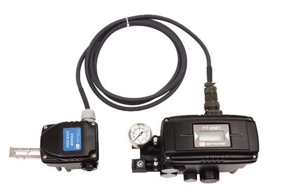
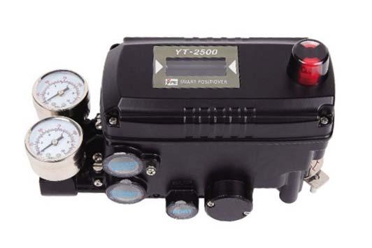
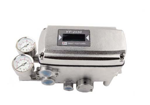
6 2. Product Description 2.1 General YT-2500/2501/2550 series Smart Valve Positioner accurately controls valve stroke in response to an input signal of 4-20mA from the controller. Built-in micro-processor optimizes the positioner s performance and provides unique functions such as Auto- Calibration, PID Control, Alarms, and HART Protocol Communications. 2.2 Main Features and Functions LCD display enables users to monitor the positioner status. Positioner operates normally during sudden changes in supply pressure and / or high vibration environment. Low air consumption level and low voltage use (8.5 V) yield to lower plant operating costs. The YT-2500/2501/2550 is compatible with most of controllers. Variable orifice can be used to minimize the hunting occurrence and optimize operating conditions. Valve system feedback is greatly improved by the accuracy and fast response of the YT- 2500/2501/2550 Different valve characteristics can be adjusted Linear, Quick Open, Equal Percentage, and Custom which user can make 16 points characterizations. Tight Shut Close and Shut - Open can be set. PID parameters can be adjusted in the field without any additional communicator. A/M switch can be used to direct supply air to the actuator or to manually operate the positioner or valve. Split range 4-12mA or 12-20mA can be set. Operating temperature for sensor module (YT-2501 series) is -40 ~ 85 C. YT- 2500/2501 series operating temperature is -30 ~ 85 C. Manual Operation allows the user to operate the valve manually. 2.3 Label Description YT-2500/2501/2550 Body Label A. Model: Indicates the model number of the positioner. B. Explosion Proof: Indicates certified explosion proof grade. C. Input Signal: Indicates input signal range. D. Operating Temp.: Indicates the allowable operating temperature. E. Supply Pressure: Indicates the supply pressure range. F. Serial Number: Indicates the unique serial number. 6 YT-2500/2501/2550 series
7 2.4 Product Number ** YT-2501 standard cable length is 5 meters. Maximum cable length is 20 meters. 7 YT-2500/2501/2550 series
8 2.5 Product Specification Model YT-2500 YT-2550 YT-2501 Motion Type Linear Rotary Linear Rotary Linear Rotary Input Signal Supply Pressure 4~20mA DC 0.14~0.7 MPa (1.4~7 bar) Stroke 10~150mm 0~90 10~150mm 0~90 10~150mm 0~90 Impedance 20mA DC Air Connection PT, NPT 1/4 Gauge Connection PT, NPT 1/8 Conduit Entry PF(G) 1/2 Protection Grade Explosion Proof IP66 Ex ia IIC T6 / T5 Ambient Temp. Operating Temp: -30~80C Explosion Temp: -40~40 C(T6) -40~60 C(T5) Sensor: -40 ~ 120 C Body: -30 ~ 80 C Explosion Temp: -40~40 C(T6) -40~60 C(T5) Linearity ±0.5% F.S. (cable length: 5 m) Hysteresis 0.5% F.S.(cable length: 5 m) Sensitivity ±0.2% F.S (cable length: 5 m) Repeatability ±0.3% F.S.(cable length: 5 m) Flow Capacity Air Consumption Output Characteristic Vibration Feedback Signal 60 LPM (Sup.=0.14 MPa) 0.01 LPM (sup=0.14 MPa) Linear, Quick Open, EQ%, User Set (16 point) No Resonance upto 6G 4~20mA (DC 10~30V) Material Aluminum Diecasting STS316 Aluminium Diecasting Weight 1.5 kg 3.5 kg 3.5 kg Painting Epoxy Powder Coating 8 YT-2500/2501/2550 series
9 2.6 Parts and Assembly YT-2500L & YT-2500R YT-2500L series exploded view YT-2500R series exploded view 9 YT-2500/2501/2550 series
10 2.7 Parts and Assembly YT Product Dimension YT-2500L 10 YT-2500/2501/2550 series
11 2.8.2 YT-2500R YT-2500R standard YT-2500R with L/S option 11 YT-2500/2501/2550 series
12 2.8.3 YT-2501L & R BODY 12 YT-2500/2501/2550 series
13 2.8.4 YT-2501L & R Sensor 13 YT-2500/2501/2550 series
14 3. Installation 3.1 Safety When installing a positioner, please ensure to read and follow safety instructions. Any input or supply pressures to valve, actuator, and / or to other related devices must be turned off. Use bypass valve or other supportive equipment to avoid entire system shut down. Ensure there is no remaining pressure in the actuator. 3.2 YT-2500/2501L Installation YT-2500/2501L should be installed on linear motion valves such as globe or gate type which uses spring return type diaphragm or piston actuators. Before proceeding with the installation, ensure following components are available. Positioner unit Feedback lever and lever spring Flange nut (bottom side of YT-2500/2501L) 4 pcs x hexagonal headed bolts (M8 x 1.25P) 4 pcs x M8 plate washer Installation Steps 1. Proper bracket must be made in order to adapt the positioner on the actuator yoke. Please consider following important points when a bracket is being designed. Positioner s feedback lever must be parallel to the ground at 50% of the valve stroke. Feedback lever connection with the pin of the actuator clamp should be installed in such a way that the valve stroke length coincides with the corresponding figure in mm marked on the feedback lever. Improper setting may cause poor linearity and may create unnecessary hunting during the operation. 2. Assemble the positioner with the bracket made in previous step by fastening the bolts. Please refer to the backside of the positioner for size of the bolts. The standard bolt size is M8 x 1.25P. Please contact Young Tech Co., Ltd for other bolt sizes. YT-2500L 14 YT-2500/2501/2550 series YT-2501L
15 3. Attach the positioner with bracket to the actuator yoke DO NOT TIGHTEN POSITIONER COMPLETELY. 4. Connect positioner s feedback lever to the actuator clamp. The hole gap on the feedback lever is 6.5mm. The connection pin s outer diameter should be less than 6.3mm. 5. Connect supply pressure to the actuator temporarily. Supply enough supply pressure to the actuator in order to position the actuator clamp at 50% of the total valve stroke. 6. Insert connection pin into the feedback lever. The pin should be inserted when the actuator clamp is at 50% of the total valve stroke. Proper way to connect feedback lever, connection pin, and lever spring <YT-2500 and YT-2501 sensor> 7. Check if feedback lever is parallel to the ground at 50% of the valve stroke. If it is not parallel, adjust the bracket or feedback link bar to make parallel. Improper installation may cause poor linearity and may create unnecessary hunting during the operation. 8. Check the valve stroke. The stroke marks are indicated on the feedback lever of the positioner. Position the connection pin at the number on the feedback lever which corresponds to the desired valve stroke. To adjust, move the bracket, the connection pin or both. Proper way of Pin Insertion 9. After installing the positioner, operate the valve from 0% to 100% stroke by using direct air to the actuator (manual set). On both 0% and 100%, the feedback lever should not touch the lever stopper, which is located on the back of the positioner. If the feedback lever touches the stopper, the positioner should be installed further away from the yoke. 15 YT-2500/2501/2550 series
16 Feedback lever should not touch lever stopper 0% ~ 100% valve stroke. 10. After the installation, tighten all of the bolts on the bracket, the feedback lever, and the connection pin. 3.3 YT-2500/2501R Installation YT-2500R should be installed on rotary motion valve such as ball or butterfly type which uses rack and pinion, scotch yoke or other type of actuators which stem rotates 90 degrees. Before proceeding with the installation, ensure following components are available. Positioner unit Fork lever and lever spring Standard rotary bracket (included with the positioner) 4 pcs x hexagonal headed bolts (M8 x 1.25P) 4 pcs x M8 plate washer YT-2501R Installation Example 16 YT-2500/2501/2550 series
17 3.3.2 Bracket information <For YT-2500/2550R> YT-2500R series is supplied with standard bracket. This bracket can be used for both fork and NAMUR lever. Please refer to below table how to adjust the bracket. Actuator stem Markings of bolt holes height (H) A-L B-L A-R B-R 20mm H : 20 H : 20, 30 H : 20 H : 20, 30 30mm H : 30 H : 20, 30 H : 30 H : 20, 30 50mm H : 50 H : 50 H : 50 H : 50 Using hexagonal bolts and washer, fasten YT-2500R with the supplied bracket. Do not tighten bolts completely before correct mounting of YT-2500R has been confirmed. Insert YT-2500R s main shaft into actuator s stem, and place the bracket align to the actuator s bolt holes. After the alignment, please fasten all of the bolts Installation Steps <For YT-2500/2550R> 1. Please check the actuator s stem height and adjust the bracket by referring to the bracket table. 2. Attached the bracket onto the actuator. It is recommended to use spring washer so the bolts will not be loosen from vibration. 3. Set rotation position of the actuator stem at 0%. For single acting actuator, it is easy to check 0% point by supplying no pressure to the actuator. For double acting actuator, check actuator stem s rotation direction clockwise or counter-clockwise - by supplying pressure to the actuator. 17 YT-2500/2501/2550 series
18 4. Install the fork lever after setting actuator s stem at 0%. Check the actuator stem s rotation direction clockwise or counter-clockwise. Installation angle of the fork lever should be 45 degrees in relation to the linear shaft. For NAMUR shaft installation, the angle does not matter. Fig. 6: Counter-clockwise and clockwise rotation. 5. After setting fork lever position, assemble lock nuts which are located on the bottom of the fork lever. Ensure to set the height of the upper fork lever between 6~11mm, which is lower than the upper bracket s height. 6. Attach the positioner to the bracket. Fix the clamping pin on the main shaft s center of the positioner and insert connection pin into the fork lever slot. This will lock to the fork lever spring. Setting alignment of the main shaft of the positioner and center of the actuator s stem is very important. Poor alignment of the main shaft and the actuator s stem decreases the positioner s durability due to unnecessary forces on the main shaft. 7. Tighten the positioner and the bracket with hexagonal-headed bolts and plate washer after checking the positioner s position. 4. Connections 4.1 Safety Supply pressure should be clean and dry air avoiding moisture, oil or dust. Always recommended to use air filter regulator (i.e. YT-200 series). Young Tech Co., Ltd has not tested positioner s operation with any other gases other than clean air. Please contact Young Tech Co., Ltd for any questions. 18 YT-2500/2501/2550 series
19 4.2 Supply Pressure Condition Dry air with at least 10 lower than ambient temperature. Avoid from dusty air. Positioner s inner filter can only filter 5 micron or larger. Avoid oil. Comply with ANSI/ISA (R1981) or ISA S (R1981). Supply pressure range is 1.4 ~ 7 kgf/cm 2 ( kpa) Set air filter regulator s pressure level 10% higher than actuator s spring range pressure. 4.3 Piping Condition Ensure inside of pipe is clean of obstructions. Do not use pipeline that is squeezed or shows any type of damamges. Pipeline should have more than 6mm of inner diameter (10mm outer diameter) to maintain flow rate. The length of pipeline system should not be extremely long. Longer pipeline system may affect flow rate due to the friction inside of the pipeline. 4.4 Connection Actuator Single acting actuator YT-2500/2550 Singe acting type positioner is set to use OUT1 port. OUT1 port should be connected with supply pressure port from actuator when using single acting type of spring return actuator. Singe acting linear (left) and rotary (right) type actuator Double acting actuator YT-2500/2550 Double acting type positioner is set to use OUT1 and OUT2 port. As input signal increases, the supply pressure will be supplied through OUT1 port. Double acting linear (left) and rotary (right) type actuator 19 YT-2500/2501/2550 series
20 4.4.3 Single acting actuator YT-2501 Single acting linear (left) and rotary (right) type actuator Double acting actuator YT-3301 Double acting linear (left) and rotary (right) type actuator 4.5 Connection Power Safety Conduit entry connection tap is PF 1/2 or G 1/2. Before connecting terminal, ensure that the power is off completely. Do not open the cover when the power is still alive. Please use ring-type rug to protect against vibration or any other external impact. Positioner with PTM options must be supplied 10~28V DC separately. For L/S option, separate 12-24V DC must be supplied. For both options, it should not exceed 30V DC. Positioner should be grounded. Please use twisted cable with conductor section are 1.25mm 2 and that is suitable for 600V (complying to the conductor table of NEC Article 310.) The outer diameter of the cable should be between 6.35 ~ 10mm. Use shield wire to protect against electromagnetic field and noise. Please do not install the cable near high noise equipments, such as high-capacity transformer or motor. 20 YT-2500/2501/2550 series
21 4.5.2 Terminal Overview Positioner Terminal IN +: Input Signal (+) IN -: Input Signal (-) FG: Ground OUT+: Feedback Signal (+) OUT-: Feedback Signal (-) Limit Switch Terminal Mechanical Type <YT-2500> 21 YT-2500/2501/2550 series

22 Limit Switch Terminal Proximity Type <YT-2500> Ground 1. Ground must be done before operating the positioner. 2. Open terminal cover and locate ground terminal plate on the right hand bottom side of the terminal plate. The outer cable entry is located at outside of the terminal. Please make sure that the resistance is less than 100ohm. 3. When using external ground, use (+) screw driver to unscrew the ground bolts. Insert outside ground bolts and spring washer into ring type terminal of the ground cables and tighten them with bolts. 4. When using inside ground, use 3mm wrench to loosen locking bolts of the terminal box cover. 5. Adjustments 5.1 Limit Switch Adjustment <YT-2500 Mechanical Type> YT-2500 series can have limit switch option. If user wants to adjust the position, please loosen cam bolts and adjust cam. 22 YT-2500/2501/2550 series
23 5.2 Limit Switch Adjustment (YT-2500 Proximity Type) 5.3 Variable Orifice Adjustment Positioner can cause hunting with extremely small size of the actuator, and by adjusting the variable orifice, the air flow rate to the actuator can be adjusted. 5.4 Option PCB Adjustment By adding option sub-pcb, the positioner can have options. There are 3 types of sub-pcb s HART only PTM only PTM + HART Installation Steps 1. Open the cover and remove the main PCB from the positioner. 2. Mount support PCB and plug sub-pcb into main PCB connector. 23 YT-2500/2501/2550 series

24 . Option Jumper ** Option Jumper must be removed, when HART option included sub-pcb is being mounted. 6. Operation 6.1 Safety Following process will operate valve and actuator. Before proceed with any AUTO Calibration, please separate valve from the entire system, so AUTO Calibration will affect entire valve process. 6.2 Button Description Positioner has 4 buttons, and they enable to perform various functions. : : <UP> & : Enter to main and sub menus, and save Return to previous menu Move to next menu, and adjust. 6.3 Run Mode (RUN) After power connection to the positioner, Run Mode will be appeared on positioner s LCD screen within 6 seconds. RUN indicates that the positioner adjusts the valve stroke according to the receiving signal. There are six types of display message in RUN Mode. 24 YT-2500/2501/2550 series
25 1. Run PV: Process Value - valve stroke % 2. Run SV %: Set Value input signal 0~100% 3. Run SV ma: Set Value input signal 4~20mA 4. Run MV: Manipulate Valve Motor Manipulate Value (digit) 5. Run Vel: Velocity Current valve stem s velocity (digit) 6. Run Err: Error Difference between SV and PV (%) To change display, push + <UP> buttons at the same time. The display will change in the order indicated above. If + pushed, the order will be appeared in opposite order. By pressing, the display will return to RUN mode Auto Calibration (AUTO CAL) Auto Calibration (AUTO CAL) automatically calibrates the positioner. AUTO CAL process takes about 2~3 minutes, and the duration of the process varies upon the size of the actuator. There are 3 types of AUTO CAL. Zero Point End Point KP, KI, KD RA / DA BIAS V_D AUTO 1 O O X X X X AUTO 2 O O O O O O AUTO HF O O O O O O BIAS X X X X O X It is recommend to perform AUTO2 calibration for initial positioner setting AUTO1 Calibration (AUTO1) AUTO1 changes zero and end points; however, KP, KI, KD will not be adjusted. It is recommended to perform AUTO1 when the positioner has been set by the valve manufacturer already, and the field user wants to re-calibrate the positioner. 6 seconds 25 YT-2500/2501/2550 series
26 AUTO2 Calibration (AUTO2) AUTO2 changes all of the parameters. It is recommended to perform AUTO2 when the positioner has been installed on the valve for the first time. 6 seconds Manual Mode (MANUAL) Manual mode is used to maneuver valve stem manually. During MANUAL, the positioner bypasses supply air to the actuator. The movement of the stroke does not affect the positioner s save data valves. 6 seconds <UP> Parameter Mode (PARAM) AUTO CAL optimizes most of the valve actuator control values. However, in some instances, hunting or oscillation may occur when the valve actuator control values are not optimized. Hunting or oscillation can be prevented by adjusting parameter values. Once parameter values have been changed, the changed values are being affected as soon as you save the value. To save the changes, please ensure to press ENTER button. There is no need to go back to RUN mode after changes are being made to observe the changes Dead-Zone (deadzone) Dead-Zone indicates the percentage of error allowance. In case of high level of packing friction, which may cause hunting, creating Dead-Zone can stable the valve operation. 26 YT-2500/2501/2550 series
 P value indicates the ratio of the compensation")

 D value indicates the derivative value of the")

27 6 seconds 2 times <UP>/ P value (KP) P value indicates the ratio of the compensation signal based on the percentage of error allowance. As the value increase, the positioner finds the target value quickly, but it is more likely to have hunting. 1time <UP>/ D value (Kd) D value indicates the derivative value of the compensation signal based on the percentage of error allowance. As the value increase, it is more likely to have hunting. As the value decreases, it can have poor linearity. 2 times <UP>/ 27 YT-2500/2501/2550 series
28 I value (KI) I value indicates the additional compensation signal based on the percentage of error allowance. As the value increase, it is more likely to have hunting. As the value decreases, the positioner will move slowly to the target position. <UP> P_ (KP_), D_ (Kd_), I_(KI_) values P_, D_, and I_ values principles are same as P, D, and I values, but these values will be activated when the error percentage is within 1% Hand Calibration Mode (HAND CAL) The positioner can be manually calibrated by entering into Hand Calibration Mode Zero-Point (PV_ZERO) and End-Point (PV_END) for Valves PZ_ZERO adjusts the zero point of the valve, and PV_END adjusts the end point of the valve. 6 seconds <UP>/ Zero Adjustment <UP>/ End Adjustment 28 YT-2500/2501/2550 series
 and End-Point (TR_END) for Transmitter TR_ZERO")
.")
 Match feedback signal with 20mA 3 End-Point")

 4 Normal / Reverse Feedback Signal (TR_NORM / REV)")
29 Zero-Point (TR_ZERO) and End-Point (TR_END) for Transmitter TR_ZERO adjusts the zero point of the transmitter (4-20mA feedback), and TR_END adjusts the end point of the transmitter (4-20mA feedback). <UP>/<DOWN) Zero Adjustment Match feedback signal with 4mA End Adjustment <UP>/<DOWN) Match feedback signal with 20mA End-Point Ratio for Valve (PE_TRIM) When reverse acting operating is used, End-Point can be adjusted within 10% of total valve stroke, without adjusting valve s zero point. 4 times <UP>/<DOWN) Normal / Reverse Feedback Signal (TR_NORM / REV) The feedback signal from the positioner can be viewed as normal or as reverse. Zero Adjustment 5 times 29 YT-2500/2501/2550 series
30 Normal / Reverse HART Signal (HT_NORM / REVS) HART signal from the positioner can be viewed as normal or as reverse. 6 times Zero Adjustment Valve Mode (VALVE) Acting Adjustment (ACT) The positioner can be set as Direct Action (DA) or Reverse Action (RA). 6 seconds <UP>/ Characteristic Adjustment (CHAR) The valve characteristic can be set on the field s requirement. There are 3 types of characteristics linear (LIN), equal percentage (EQ), and quick open (QO). 30 YT-2500/2501/2550 series
 Tight Shut Open allows the valve to open completely as the input signal reaches around 20mA.")
31 <UP>/ User Characteristics (USER SET) In case positioner requires a specific characteristic, the valve characteristic curve can be made by selecting up to 16 points of the curve. 6 seconds 2 times <UP>/ <UP> Repeat step if necessary Tight Shut Open (TSHUT OP) Tight Shut Open allows the valve to open completely as the input signal reaches around 20mA. 6 seconds <UP>/ 31 YT-2500/2501/2550 series
32 Tight Shut Close (TSHUT CL) Tight Shut Close allows the valve to close completely as the input signal reaches around 4mA. 6 seconds 4 times <UP>/ Split Range Mode (SPLIT) The valve can be operated by split range control 4~12mA or 12~20mA. 6 seconds 5 times <UP>/ Custom Zero Setting Mode (CST ZERO) Custom Zero Setting Mode allows the user to set any specific point as zero position. For example, the zero point can be set at input signal of 7mA. 6 times <UP>/ Custom End Setting Mode (CST ENd) Custom End Setting Mode allows the user to set any specific point as end position. For example, the end point can be set at input signal of 11mA. The difference between zero and end point must be greater or equal to 4mA. 32 YT-2500/2501/2550 series
33 7 times <UP>/ Interpolation Mode (ITP OFF / ON) Positioner can control the valve accurately if the feedback lever angle range is within designed range. For some instance, the angle exceeds the suggested range angle. Positioner can reduce the error through interpolation. 8 times <UP>/ View Mode (VIEW) Different information can be shown on the positioner s LCD. 4 times <UP>/ Description YT-25XX VERSION HART V POL AddR Positioner model Main software version HART protocol version HART protocol channel address bias 25 BIAS value when valve position is at 25% bias 75 BIAS value when valve position is at 75% 33 YT-2500/2501/2550 series
34 0Y 0d FULL_OP FULL_CL VM NOR Erro VALUE I ABS Total used time duration. If a unit was used less than 1 minute, the time will not accumulate. Time elapsed for valve to fully open Time elapsed for valve to fully close. Type of valve stroke on LCD. (in percentage or in value) Error code or warning message. Current I value Absolute resistance value. 7. Error and Warning Code 7.1 Error code Error Code Code Description and Cause Action MT ERR L MT ERR H CHK AIR Positioner is improperly installed. Positioner is not parallel to the ground at 50% point. Lever is at lower position than actual 50% point. Positioner is improperly installed. Positioner is not parallel to the ground at 50% point. Lever is at higher position than actual 50% point. Valve does not operate when positioner receive Full Open signal during the auto calibration. Re-install the positioner. Ensure the feedback lever does not touch the lever stopper at 0% and 100%. Re-install the positioner. Ensure the feedback leer does not touch the lever stopper at 0% and 100%. Check supply pressure level. RNG ERR C D Adjust bracket so the positioner Operating angle is too small due to can be mounted closer to improper positioner installation. actuator. Error of 10% or more persists more than 1 minute. Perform BIAS calibration. No valve movement. Check setting pressure of actuator. High level of valve friction Changes in setting pressure of actuator. I-value reaches at maximum or minimum limit. Perform auto calibration. Changes in valve friction. Check setting pressure of actuator. Changes in setting pressure of actuator. 34 YT-2500/2501/2550 series
35 7.2 Warning code Warning Code Description Action B F G H Re-install the positioner. Ensure the feedback lever does not Pv Span Pv Zero range is below 500. touch the lever stopper at 0% and The angle of feedback lever is too small. 100%. After re-installation, perform AUTO1. Full open/close elapsed time is less Use variable orifice. than 1 second. Use larger actuator. Actuator size is too small. Re-install the positioner. Ensure the feedback lever does not Pv is below 100. touch the lever stopper at 0% and The angle of feedback lever is too large. 100%. After re-installation, perform AUTO1 Re-install the positioner. Ensure the feedback lever does not Pv is over touch the lever stopper at 0% and The angle of feedback lever is too large. 100%. After re-installation, perform AUTO1 35 YT-2500/2501/2550 series
36 8. Main Software Map 36 YT-2500/2501/2550 series
37 Manufacturer: Young Tech Co., Ltd #3022, Hagun-ri, Yangchon-myeon Kimpo-si, Kyeonggi-do, South Korea Tel: Fax: Copyright Young Tech Co., Ltd. All Rights Reserved. 37 YT-2500/2501/2550 series
SMART POSITIONER YT-3300/3301 SERIES
 SMART POSITIONER YT-3300/3301 SERIES PRODUCT MANUAL VERSION 1.02 Contents 1. Introduction 5 1.1 General information for the users. 5 1.2 Manufacturer Warranty 5 2. Product Description.. 6 2.1 General..
SMART POSITIONER 6000/6050 SERIES
 SMART POSITIONER 6000/6050 SERIES PRODUCT MANUAL VERSION 1.00 Contents 1. Introduction 5 1.1 General information for the users. 5 1.2 Manufacturer Warranty 5 2. Product Description.. 6 2.1 General.. 6
SMART POSITIONER SS3400 SERIES
 SMART POSITIONER SS3400 SERIES PRODUCT MANUAL VERSION 1.03 Contents 1. Introduction 4 1.1 General information for the users. 4 1.2 Manufacturer Warranty 4 1.3 Explosion Proof Warning. 3 2. Product Description..
SMART POSITIONER YT-3400 SERIES
 SMART POSITIONER YT-3400 SERIES USER'S MANUAL 1 V.1.02 Table of Contents Introduction 4 Manufacturer Warranty 4 Product Description 5 Main Features and Functions 5 Label Description 6 Suffix Symbol 7 Specification
SMART POSITIONER YT-2400 SERIES USER'S MANUAL
 SMART POSITIONER YT-2400 SERIES USER'S MANUAL YTC V.1.02 1 Table of Contents Contents Page No. Introduction 4 Manufacturer Warranty 4 Product Description 5 Main Features and Functions 5 Label Description
SMART POSITIONER YT-3400 / 3450 SERIES PRODUCT MANUAL
 SMART POSITIONER YT-3400 / 3450 SERIES PRODUCT MANUAL VERSION 1.03 Contents 1. Introduction 4 1.1 General information for the users. 4 1.2 Manufacturer Warranty 4 1.3 Explosion Proof Warning. 3 2. Product
Installation- Linear. I & M Mark 17X Series. Mark 17X Linear Installation
 I & M Mark 17X Series 3170 Wasson Road Cincinnati, OH 45209 Phone 513.533.5600 Fax 513.871.0105 (f) info@richardsind.com www.jordanvalve.com Installation & Maintenance Instructions for the Mark 17X Series
Electro-Pneumatic Positioner YT-1000 / 1050 SERIES
 Electro-Pneumatic Positioner YT-1000 / 1050 SERIES PRODUCT MANUAL VERSION 1.01 Contents 1. Introduction 4 1.1 General information for the users. 4 1.2 Manufacturer Warranty 4 1.3 Explosion Proof Warning.
SMART POSITIONER YT-2500 SERIES USER'S MANUAL
 SMART POSITIONER YT-2500 SERIES USER'S MANUAL YTC V.1.01 1 Table of Contents Introduction 4 Manufacturer Warranty 4 Product Description 5 Main Features and Functions 5 Label Description 6 Suffix Symbol
SMART POSITIONER YT-2300 SERIES USER'S MANUAL
 SMART POSITIONER YT-2300 SERIES USER'S MANUAL Table of Contents Contents Page No. Introduction 4 Manufacturer Warranty 4 Product Description 5 Main Features and Functions 5 Label Description 6 Suffix Symbols
SMART POSITIONER YT-2500/2550 SERIES USER'S MANUAL
 SMART POSITIONER YT-2500/2550 SERIES USER'S MANUAL YTC 1 V.1.04 Table of Contents Introduction 4 Manufacturer Warranty 4 Product Description 5 Main Features and Functions 5 Label Description 6 Suffix Symbol
Electro-Pneumatic Positioner YT-1000 / 1050 SERIES
 Electro-Pneumatic Positioner YT-1000 / 1050 SERIES PRODUCT MANUAL VERSION 1.01 Contents 1. Introduction 4 1.1 General information for the users. 4 1.2 Manufacturer Warranty 4 1.3 Explosion Proof Warning.
INSTRUCTION MANUAL. CVS Series 3400 Flameproof Smart Positioner. Introduction
 INSTRUCTION MANUAL CVS Series 3400 Flameproof Smart Positioner Introduction The CVS 3400 is a CSA approved and Explosion Proof Rated EX d IIC T6/T5, Class 1, Zone 1, Group A. Additional certifications
Series 185/285 Smart Positioners
 Series 185/285 Smart Positioners Bulletin V-185/285 Specifications - Installation and Operating Instructions DOUBLE ACTION SINGLE ACTION LCD SCREEN SMART POSITIONER 3-47/64 [95.00] Series 185 3-27/32 [97.50]
Pneumatic Positioner PNY Series USER'S MANUAL. Max-Air Technology. Version 1.0
 USER'S MANUAL Max-Air Technology Version 1.0 Table of Contents Introduction 3 Manufacturer Warranty 3 Product Description 4 Main Features and Functions 4 Operation Logic 4 Specification 5 Parts and Assembly
User s Manual. Pneumatic Positioner. Series 58. J Flow. Series 58. J Flow
 Pneumatic Positioner Series 58 User s Manual J Flow Series 58 J Flow Series 58 J Flow Controls, LLC 14 De Camp Cincinnati, OH 45216 Phone: 513-731-2900 Fax 513-731-6939 www.jflowcontrols.com Introduction
VOLUME BOOSTER RELAYS YT-310 / 315 SERIES
 VOLUME BOOSTER RELAYS YT-310 / 315 SERIES PRODUCT MANUAL VERSION 1.02 Contents 1. Introduction 3 1.1 General information for the users. 3 1.2 Manufacturer Warranty 3 2. Product Description.. 4 2.1 General..
CVS 2400 SERIES SMART POSITIONER
 CVS 2400 SERIES SMART POSITIONER Product Manual PRODUCT DRIPTION YT-2400 Smart Valve Positioner accurately controls valve stroke according to input signal of 4~20mA input from a controller. In addition,
YT-2600 SERIES VERSION 1.07
 SMART POSITIONER YT-2600 SERIES PRODUCT MANUAL VERSION 1.07 Contents 1. Introduction... 4 1.1 General Information for the users... 4 1.2 Manufacturer Warranty... 4 1.3 Explosion Proof Warning & Specific
YT-2500 / 2550 / 2501 SERIES
 SMART POSITIONER YT-2500 / 2550 / 2501 SERIES PRODUCT MANUAL VERSION 1.10 Contents 1. Introduction... 5 1.1 General Information for the users... 5 1.2 Manufacturer Warranty... 5 1.3 Explosion Proof Warning
TMP-3000 VERSION 1.01
 VERSION 1.01 Contents 1. Introduction... 4 1.1 General Information for the users... 4 1.2 Safety precautions and Manufacturer Warranty... 4 2. Product Description... 5 2.1 General... 5 2.2 Main Features
RTX1000 SERIES ELECTRO-PNEUMATIC POSITIONER
 RTX1000 SERIES ELECTRO-PNEUMATIC POSITIONER Installation Operation and Maintenance Manual RTX-IOM-RTX1000/1000L-R01-0416 Page 1 of 26 Contents 1. Introduction... 4 1.1. General information... 4 1.2. Definitions...
YT-1200 Series VERSION 1.02
 YT-1200 Series PRODUCT MANUAL VERSION 1.02 Contents 1. Introduction... 4 1.1 General Information for the users... 4 1.2 Manufacturer Warranty... 4 1.3 Explosion Proof Warning (Only for external explosion
YT-720 SERIES. Rotork YTC Limited VERSION 1.07
 YT-720 SERIES PRODUCT MANUAL YT-720S YT-720D Rotork YTC Limited VERSION 1.07 Contents 1. Introduction... 3 1.1 General Information for the users... 3 1.2 Manufacturer Warranty... 3 1.3 Explosion Proof
Fig Single-Acting Rotary Smart Positioner
 Fig. 3303 Single-Acting Rotary Smart Positioner Order Information Model No. EC03303RSN52000S Econ series 3300 Smart Positioner for quarter turn actuators in single acting version. This positioner regulates
Series 60. New Smart Positioner. Compact design Convenient & powerful function Enhanced reliability
 Series 60 New Smart Positioner Compact design Convenient & powerful function Enhanced reliability J Flow Controls, LLC 14 De Camp Cincinnati, OH 45216 Phone: 513-731-2900 Fax 513-731-6939 www.jflowcontrols.com
Pneumatic-Pneumatic Positioner YT-1200L,R Installation manual
 Installation Safety Warning When installing a positioned, please ensure to read and follow safety instruction. All input and supply pressure to valve, actuator, and other related devices must be turned
Smart Positioner YT-2400L,R Installation manual
 Installation Safety Warning When installing a positioner, please ensure to read and follow safety instruction. All input and supply pressure to valve, actuator, and other related devices must be turned
Pneumatic Positioner RTX - Series USER S MANUAL. ROTEX P/P Ver. 0.1 Dated: MAY / 2009 REV 01: SEP/2010 Page 1 of 16
 Pneumatic Positioner RTX - Series USER S MANUAL MODEL RTX 1200 AMBIENT TEMP. 20 C ~ 70 C WEATHER PROOF IP 65 SUPPLY PR. 1.4 ~ 7.0 bar INPUT SIGNAL 0.2 ~ 1.0 bar SERIAL NO. ROTEX P/P Ver. 0.1 Dated MAY
YT-200 / 205 / 220 / 225 Series YT-200 YT-205 YT-220 YT-225 VERSION 1.01
 YT-200 / 205 / 220 / 225 Series PRODUCT MANUAL YT-200 YT-205 YT-220 YT-225 VERSION 1.01 Contents 1. Introduction... 3 1.1 General Information for the users... 3 1.2 Manufacturer Warranty... 3 2. Product
Electro-Pneumatic Positioner RTX - Series USER S MANUAL. ROTEX E/P Ver. 0.1 Dated: dd / mm / yy Page 1 of 18
 Electro-Pneumatic Positioner RTX - Series USER S MANUAL ROTEX E/P Ver. 0.1 Dated dd / mm / yy Page 1 of 18-1 - RTX1000-R2-2011 Table of Contents Introduction 3 Manufacturer Warranty 3 General Service Information
YT-3300 / 3350 / 3303 / 3301 SERIES
 SMART POSITIONER YT-3300 / 3350 / 3303 / 3301 SERIES PRODUCT MANUAL YT-3300 YT-3300 with limit switch YT-3350 YT-3303 YT-3303 YT-3301 VERSION 1.11 Contents 1. Introduction... 5 1.1 General Information
SS3 Linear / Rotary. Smart Valve Positioner. Smart performance with innovative and ever-strong coil drive even under harsh working environments
 Smart Valve Positioner SS3 Linear / Rotary Smart performance with innovative and ever-strong coil drive even under harsh working environments Easy and quick auto-calibration Detecting RA (reverse acting)
Operation Manual Electro-Pneumatic Positioner Model: NT-1000R (Rotary Type) NUTORK CORPORATION
 NUTORK CORPORATION") Operation Manual Electro-Pneumatic Positioner Model: NT-1000R (Rotary Type) Integral Mounted Air Set Dome Indicator NUTORK CORPORATION Table of Contents Introduction 2 Manufacturer Warranty Product Description
Operation Manual Electro-Pneumatic Positioner Model: NT-1000R (Rotary Type) Integral Mounted Air Set Dome Indicator NUTORK CORPORATION Table of Contents Introduction 2 Manufacturer Warranty Product Description
YT-1000 / 1050 Series
 YT-1000 / 1050 Series PRODUCT MANUAL VERSION 1.07 Contents 1. Introduction... 5 1.1 General Information for the users... 5 1.2 Manufacturer Warranty... 5 1.3 Explosion Proof Warning (Only for explosion
YT-520S YT-520D YT-525S YT-525D YT-530S YT-530D YT-535S YT-535D
 YT-520 / 525 / 530 / 535 Series PRODUCT MANUAL YT-520S YT-520D YT-525S YT-525D YT-530S YT-530D YT-535S YT-535D VERSION 1.04 Rotork YTC Limited Contents 1 Introduction...3 1.1 General Information for the
AP ATEX AIRPOWER POSITIONERS AP2000 FEATURES AP1000 & AP1200 FEATURES OPTIONS OPTIONS
 AP1000-2000 Airpower positioners are a robust range of rotary or linear valve positioners in AP1000 electro-pneumatic (4-20mA), AP1200 pneumatic (3-15 psi) or AP2000 programmable smart type. Designed to
SP-20 Input. Installation and Operating Instructions Electro-Pneumatic Linear Positioner. Description of Device. Part Number System
 Description of Device VALMAC Posi-Zest SP-2000 Series is the advanced control device for a linear control valve that provides unparalleled stability in difficult environments. Easy maintenance Precise
Electro-Pneumatic Linear Positioner Installation and Operation Instructions B GB
 Installation and Operation Instructions 99.66.02-B GB Description of Device (4-~20mA) is the advanced control device for a linear control valve that provides unparalleled stability in difficult environments
Installation and Operating Instructions Electro-Pneumatic Rotary Positioner SP-21. Description of Device. Part Number System
 Description of Device VALMAC Posi-Zest SP-2100 Series is the advanced control device for a rotary control valve that provides unparalleled stability in difficult environments. Easy Maintenance Precise
POSITIONERS and Controls for Complete Valve Automation
 CONTROLS A Division of AT Controls Pneumatic & Electro-Pneumatic POSITIONERS and Controls for Complete Valve Automation 1 SS SERIES SS Features Easy and quick auto-calibration Detecting RA (reverse acting)
Moniteur INSTALLATION & OPERATING INSTRUCTIONS. SERIES 40 Positioners. Installation and Operating Instructions Series 40 Positioners.
 INSTALLATION & OPERATING INSTRUCTIONS SERIES 40 Positioners Form IO2-0406 Description of Device Moniteur's Series 40 pneumatic (3-15psi) and electropneumatic (4-20mA) positioners are advanced control devices
SS2 Linear / Rotary Smart Valve Positioner
 COTROLS A Division of AT Controls Smart performance with innovative and ever-strong coil drive even under harsh working environments Also available in REMOTE TYPE 316 STAILESS STEEL BODY Smart performance
Instruction and Operating Manual
 M/SS2/E 01 2011 Instruction and Operating Manual Smart Valve Positioner SS2L / SS2R Series Contents 1. Introduction 2 11.5 Sub-Parameters Flow Diagram 2. Overview of Structure 3 11.5.1 Change of Input
Smart Valve Positioner. TS800Series. Instruction Manual
 Smart Valve Positioner TS800Series Instruction Manual Ver. PM-TS800EN-8/2017 Table of Contents 1 Introduction------------------------------------------------------------------------------------- 4 1.1
PRODUCTS CATALOG (2018) TISSIN CO.,LTD. Smart Valve Positioner. Electro-Pneumatic Positioner. Volume Booster. Lock Up Valve. Air Filter Regulator
 TISSIN CO.,LTD. Smart Valve Positioner. Electro-Pneumatic Positioner. Volume Booster. Lock Up Valve. Air Filter Regulator") PRODUCTS CATAOG (08) TISSIN CO.,TD. Smart Valve Positioner Electro-Pneumatic Positioner Volume Booster ock Up Valve Air Filter Regulator Solutions for control valve system About Tissin Solutions for control
PRODUCTS CATAOG (08) TISSIN CO.,TD. Smart Valve Positioner Electro-Pneumatic Positioner Volume Booster ock Up Valve Air Filter Regulator Solutions for control valve system About Tissin Solutions for control
Smart Valve explorer Smart Valve Positioner for Rotary Valve. Model SVX100 / SVX102
 No. SS2-SVX100-0100 Smart Valve explorer Smart Valve Positioner for Rotary Valve Model SVX100 / SVX102 OVERVIEW Smart Valve explorer (SVX) models SVX100 and SVX102 are microprocessor-equipped, currentpneumatic
Electro-Pneumatic Positioner Series 830/831-WP/EX. Operation & Maintenance Manual
 Electro-Pneumatic Positioner Series 830/831-WP/EX Operation & Maintenance Manual Electro-Pneumatic Positioner Model 830/831- WP/EXP This operation & maintenance manual corresponds to Forbes Marshall Arca
TOP-QUALITY PNEUMATIC ACTUATOR
 TOP-QUALITY PNEUMATIC ACTUATOR BS EN ISO 9001:2000 INTRODUCTION PDS series Pneumatic Actuators are designed using Scotch-Yoke technology from PDS 50 to the largest of PDS 200. Scotch-Yoke technology is
Type Installation, Operation and Maintenance Instructions. Ordering Information. Contents CA20 -
 Type 2000 Pneumatic and Electropneumatic Valve Positioner Installation, Operation and Maintenance Instructions Ordering Information Use this coding system to order Model CA20 - Type of Positioner 00 P/P
TECHNICAL BULLETIN. Logix 510si Series Digital Positioner. Experience In Motion FCD LGENTB /09
 Logix 510si Series Digital Positioner TECHNICAL BULLETIN FCD LGENTB0510-01 09/09 Experience In Motion Introduction The Logix 510si series are single acting, user-friendly digital positioners. As all positioners
Features. Flexibility
 The V100 positioner can be ordered as a base model pneumatic positioner, converted to standard NEMA 4X electropneumatic, EX model, or FF (fail freeze) model in a matter of minutes, without removing the
SMART VALVE POSITIONER 4 to 20 ma + HART Digital Communication. smar B87
 SMART VALVE POSITIONER to ma + HART Digital Communication B87 DESCRIPTION The FY microprocessor based positioner provides fast and accurate positioning of diaphragm or cylinder actuators. The FY produces
V200 Positioner. V200 P Pneumatic Positioner. V200 E Electropneumatic Positioner. Housing Material: Cast aluminium with polyester coating
 V200 Positioner Housing Material: Cast aluminium with polyester coating Indicator Options: Flat pointed indicator or raised indicator (red/green or yellow/black) One housing for pneumatic or electropneumatic
V200 Series Positioners
 V200 Series Positioners In a single compact and rugged housing The V200 positioner incorporates the flexibility of converting from a pneumatic unit to several versions of an electropneumatic unit, and
Series 3730 Electropneumatic Positioner Type
 Series 3730 Electropneumatic Positioner Type 3730-1 Application Single-acting or double-acting positioner for attachment to pneumatic control valves. Self-calibrating, automatic adaptation to valve and
Control Valves Positioner
 Control Valves Positioner HiFlo Valve Positioner Easy calibration Corrosion-resistant cover and base Withstands 150 psi at all parts Two -sided cam for easy field reversibility Optional / NPT for piped
Control Valves Positioner
 Control Valves Positioner HiFlo HiFlo Valve Positioner Corrosion-resistant cover and base Easy calibration Withstands 150 psi at all parts Two -sided cam for easy field reversibility Optional / NPT for
LTX RF LEVEL SENSOR. Instruction Manual
 LTX RF LEVEL SENSOR Instruction Manual FOR MODELS LTX01, LTX02, LTX05 Intempco Document No: LTX - M01 Rev. 1 Issue Date: April 2005 LTX01 RF LEVEL SENSOR USER MANUAL Software Rev : Rev. Date : June 2004
Instruction and Operating Manual
 Instruction and Operating Manual Electro-Pneumatic Positioner Power-Genex Ltd. Contents 1. Safety Instructions / Precautions 2 2. Description 7 3. Description 7 4. Specifications 8 5. Part Numbering System
Valve Positioners Series 760P/E Valve Positioners
 Introduction Features & Benefits Universal design and choice of interchangeable AMUR IEC 54-6 rectilinear or VDI/VDE 845 rotary mountings provide wide application flexibility Double-acting or single-acting
V200 Series Positioners
 V200 Series Positioners In a single compact and rugged housing The V200 positioner incorporates the flexibility of converting from a pneumatic unit to several versions of an electropneumatic unit, and
Type Type 1001 Transducers. I/P & E/P Transducers
 Type 1001 I/P & E/P Description The Type 1001 is a patented family of electropneumatic instruments that is used to reduce a supply pressure to a regulated output pressure which is directly proportional
CONTROL VALVE ACCESSORIES CVA : 0611 ELECTRO PNEUMATIC / PNEUMATIC POSITIONER POSITION TRANSMITTER SIL
 ELECTRO PNEUMATIC / PNEUMATIC POSITIONER POSITION TRANSMITTER CVA : 0611 SIL Next generation of Positioner design featuring better performance and ease of setup has taken ELECTRO-PNEUMATIC POSITIONER RTX1000
ARCAPRO positioner. Positioner customized for specific tasks
 ARCAPRO ARCAPRO Positioner customized for specific tasks 2 3 1 A linear function between the input signal and stroke is the best way to ensure maximum control precision. Control valves with pneumatic actuators,
EB EN. Type 3372 Electropneumatic Actuator. Translation of original instructions
 EB 8313-1 EN Translation of original instructions V2001-IP Control Valve Type 3372 0511/0531 Electropneumatic Actuator with Type 3321 Valve Type 3372 Electropneumatic Actuator Edition July 2013 Note on
Pneumatic or Electropneumatic Positioner for Rotary Actuators Type Fig. 1 Type 3761 Positioner. Mounting and Operating Instructions EB 8386 EN
 Pneumatic or Electropneumatic Positioner for Rotary Actuators Type 3761 Fig. 1 Type 3761 Positioner Mounting and Operating Instructions EB 8386 EN Edition June 2004 Contents Contents Page 1 Design and
Accord Logix Series 1000 Digital Positioner
 Accord GENERAL INFORMATION The following instructions are designed to assist in unpacking, installing and performing maintenance as required on Logix Series 1000 Digital Positioners. Series 1000 is the
TZIM. Electropneumatic Analog Positioner 10/ EN
 TZIM Electropneumatic Analog Positioner EP001XA.tif Q Convenient, simple design Q Easy to handle Q User-friendly operation, easy to understand Q Reliable concept, I/P conversion through the 500,000 times
Spring Cylinder Rotary Actuator
 Spring Cylinder Rotary Actuator Rotary Actuator Spring Cylinder Rotary Actuators High torque and pneumatic stiffness combine together in the Mascot "Spring cylinder rotary actuator" These characteristics
Jordan Control Valve Series
 Jordan Control Valve Series Control Valves A control valve is used to manipulate flowing fluids like, gas, water, steam or process solutions. It compensates for changes in flow or pressure and regulates
FasTrak High Capacity Smart Positioner
 FasTrak High Capacity Smart Positioner 2 CCI provides the next level of control valve performance CCI provides the next level of control valve performance with FasTrak, a high capacity digital positioner
TECHNICAL BULLETIN. Logix 520MD Series Digital Positioner. Experience In Motion FCD LGENTB /09
 Logix 520MD Series Digital Positioner TECHNICAL BULLETIN FCD LGENTB0520-01 11/09 Experience In Motion Introduction The Logix 520MD Series combines superior positioning and tuning functions with convenient
Smart Valve Positioner for Rotary Valve
 OVERVIEW Smart Valve Positioner for Rotary Valve Model SVX is microprocessor-equipped, electropneumatic smart valve positioner for rotary valves. The SVX receives a DC current signal from control devices
Corrosion Resistant Pneumatic Positioners Model 4700P and 4700E
 Corrosion Resistant Pneumatic Positioners Specification Data CS2007 4/98 Table of Contents Foreword............................................................. 2 Numbering System.....................................................
SP500 Electropneumatic Smart Positioner
 3.568.5275.300 IM-P343-35 CH Issue 3 SP500 Electropneumatic Smart Positioner Installation and Maintenance Instructions 1. Index 2. Safety information 3. Technical information 4. Options 5. Installation
ELECTRONIC CONTROL ACTUATOR
 ELECTRONIC CONTROL ACTUATOR Nucom Series LINEAR TYPE Nucom L25 Nucom L50 OPERATION MANUAL Koei Industry Co., Ltd. FOR YOUR SAFETY In order for better and safety use of the product for a long period, please
Operation and Maintenance Instructions Manual BOOSTER. Volume amplifier
 Operation and Maintenance Instructions Manual BOOSTER Volume amplifier 1. GENERAL INFORMATION... 3 2. TECHNICAL SPECIFICATIONS... 3 3. DIMENSIONAL DESIGN... 4 3.1 BOOSTER WITHOUT SIGNAL ADAPTER... 4 3.2
The T5220 Series Electro-Pneumatic Transducer converts a DC current or voltage input signal to a directly proportional pneumatic output.
 GENERAL INFORMATION T5220 SERIES TRANSDUCER Electro-Pneumatic (I/P, E/P) APPLICATIONS The T5220 Series Electro-Pneumatic Transducer converts a DC current or voltage input signal to a directly proportional
FIELDVUE DVC5000f Series Digital Valve Controllers for FOUNDATION Fieldbus
 DVC5000f Series FIELDVUE DVC5000f Series Digital Valve Controllers for FOUNDATION Fieldbus Instruction Manual Form 5445 Introduction Installation Initial Setup and Calibration Detailed Setup Calibration
Valve Positioners Series 760P/E Valve Positioners
 Introduction Features & Benefits Universal design and choice of interchangeable AMUR IEC 54-6 rectilinear VDI/VDE 845 rotary mountings provide wide application flexibility Double-acting or single-acting
Operating Instructions. Pneumatic Control Valve Low Temperature. Type Series GS3
 Operating Instructions Pneumatic Control Valve Low Temperature Type 8026 Series GS3 With: Digital Positioner Type 8048 Electro-pneumatic Positioner Type 8047 Pneumatic Positioner Type 8047 Version: 03/2006
Pneumatic Actuators. TGA Specifications
 Pneumatic Actuators The TGA model is a double-action pneumatic actuator perfect for on/off control of the various types of butterfly valves. With an optional positioner, it can also be used for flow rate
TOP-QUALITY PNEUMATIC ACTUATOR
 TOPQUALITY PNEUMATIC ACTUATOR BS EN ISO 9001:2000 INTRODUCTION PDS series Pneumatic Actuars are designed using ScotchYoke technology from PDS 50 the largest of PDS 200. ScotchYoke technology is well known
SMART VALVE POSITIONER 4 to 20 ma + HART Digital Communication. smar
 SMART VALVE POSITIONER to ma + HART Digital Communication smar DESCRIPTION The FY microprocessor based positioner provides fast and accurate positioning of diaphragm or cylinder actuators. The FY produces
Installation & Operation Manual
 Installation & Operation Manual (I-TORK PDS Series Pneumatic Actuator) PDS-M0108/1010 74-6, Chun Ui-Dong, Won Mi-Gu, Bucheon, Kyoung Ki-Do, Korea Tel : 82-2-855-1365, 66 Fax : 82-2-855-1367 E-mail : roy75@i-tork.com
Smart Valve Positioner 700 Series with HART Communication Protocol
 No. SS2-AVP702-0100 Smart Valve Positioner 700 Series with HART Communication Protocol OVERVIEW The Smart Valve Positioner 700 Series (model number: AVP7**) not only inherits the reliability of the core
Damper Actuator Installation
 FANs 268.1, 977, 1628.3 Installation Bulletin EPP-1000 Issue Date 0800 EPP-1000 Series Electro-Pneumatic Positioners A pplication The EPP-1000 is designed for applications where electronic control of pneumatic
Mounting and operating instructions EB 5801 EN. Electric Actuators Type 5801 (Rotary Actuator) Type 5802 (Linear Actuator)
 Type 5802 (Linear Actuator)") Electric Actuators Type 5801 (Rotary Actuator) Type 5802 (Linear Actuator) Linear Actuator with Type 3260 Control Valve Rotary actuator with lever system Linear actuator with Type 3321 (V2001) Control
Electric Actuators Type 5801 (Rotary Actuator) Type 5802 (Linear Actuator) Linear Actuator with Type 3260 Control Valve Rotary actuator with lever system Linear actuator with Type 3321 (V2001) Control
Smart Valve Positioner 700 Series with HART Communication Protocol
 No. SS2-AVP702-0100 Smart Valve Positioner 700 Series with HART Communication Protocol OVERVIEW The Smart Valve Positioner 700 Series (model number: AVP7**) not only inherits the reliability of the core
Model WEP Electro-pneumatic positioner. WEP positioner A valve control without compromise
 Data Sheet DS/WEP-EN Rev. C Model WEP Electro-pneumatic positioner WEP positioner A valve control without compromise Standard - ma input Single acting, force-balance operating principle Excellent dynamic
V200 Series Positioners
 V200 Series Positioners In a single compact and rugged housing The V200 incorporates the flexibility of converting from a pneumatic unit to several versions of an electropneumatic unit, and the ability
VALVE ACCESSORIES & CONTROLS V200 POSITIONER A POSITIONER THAT OFFERS IT ALL IN ONE COMPACT, SIMPLE, HOUSING
 VALVE ACCESSORIES & CONTROLS V200 POSITIONER A POSITIONER THAT OFFERS IT ALL IN ONE COMPACT, SIMPLE, HOUSING WWW.VACACCESSORIES.COM 205-678-0507 The V200 Positioner Internal I/p with simple loop test points.
Type 3761 Pneumatic or Electropneumatic Positioner for Rotary Actuators. Fig. 1 Type 3761 Positioner. Mounting and Operating Instructions EB 8386 EN
 Type 3761 Pneumatic or Electropneumatic Positioner for Rotary Actuators Fig. 1 Type 3761 Positioner Mounting and Operating Instructions EB 8386 EN Edition July 2007 Contents Contents Page 1 Design and
Metal tube flowmeters. Series SC250. Metal Tube Flow Meters. Series SC250. Variable area flowmeter for liquids, gases and steam
 Metal tube flowmeters Variable area flowmeter for liquids, gases and steam Metallic or plastic tube with a robust construction Indication by means of magnetic coupling Scales calibrated in l/h, m 3 /h,
ELECTRONIC CONTROL ACTUATOR
 ELECTRONIC CONTROL ACTUATOR Nucom Series LINEAR TYPE Nucom L50S OPERATION MANUAL Koei Industry Co., Ltd. FOR YOUR SAFETY In order for better and safety use of the product for a long period, please observe
Installation, Operation & Maintenance Manual
 APL-2 Series Valve Position Monitor Installation, Operation & Maintenance Manual Address : Seonggok-dong, 155, Byeolmang-ro, Danwon-gu, Ansan-si, Gyeonggi-do, South Korea Tel : +82-31-488-8266, Fax : +82-31-488-8269,
K10 Intrinsically Safe Electro-Pneumatic Positioner Operating Manual
 K0 Intrinsically Safe Electro-Pneumatic Positioner Operating Manual Pneumatic Connection Outlet Port Gauge Single Acting Actuator (Spring Return): For single acting actuators Outlet Port 2 is to be plugged.
SP2 Options Installation and Maintenance Instructions
 3439152/2 IM-P343-22 CH Issue 2 SP2 Options Installation and Maintenance Instructions 50% SP2 1 2 3 4 5 General safety information Options Electrical connections Programming and commissioning travel switches
Type 4746 Electric or Pneumatic Limit Switch
 Type 4746 Electric or Pneumatic Limit Switch Application Limit switches with inductive, electric or pneumatic contacts for attachment to pneumatic or electric control valves, to Type 4763 Electropneumatic