CVS 2400 SERIES SMART POSITIONER
|
|
|
- Amelia Walker
- 5 years ago
- Views:
Transcription


1 CVS 2400 SERIES SMART POSITIONER Product Manual PRODUCT DRIPTION YT-2400 Smart Valve Positioner accurately controls valve stroke according to input signal of 4~20mA input from a controller. In addition, a highly efficient micro-processor performs various, powerful functions like Auto-calibration, PID control, alarm, and HART protocol. MANUAL DRIPTION Our products are produced and inspected under strict standards. In order to use our products appropriately and efficiently, we recommend that users read this manual carefully. This manual could change without prior notice. This manual, in whole, or part, should not be transcribed or copied without approval by SAFETY & WARRANTY *Before handling the YT-2400, it is absolutely imperative that users read and observe the safety instructions in this manual to ensure the protection and safety of its operators. * is not responsible for the damage caused by users repair or conversions of the item. If the repair or conversion is necessary please contact CVS Controls Ltd. WARNING: The following information is related to the explosion proof rating, so please note that operations/distribution should be handled with great care. 1. Open cover once power is off. After operation, close the cover, screwing it back on. Be careful not to damage the threads or screws. 2. Be careful not to lose the E-Stopping Ring. (2) Hex. Head socket screw(m6x20) Don t unscrew (4EA) (1) Hex. Head socket screw(m4x5) Don t unscrew (1EA) (3) Hex. Head socket screw (M4X 15) Don t unscrew (2EA) (4) Hex. Head socket screw(m5x25) Don t unscrew (5EA) Retaining Ring E type (#7) Don t remove from the shaft (1EA)

2 Notes on Maintenance of Explosion Proof Structure in Hazardous Area Confirm that the power is shut off before opening the cover. Confirm the operating conditions so that the explosion proof rating is available and ensure not to use beyond that rating. The explosion proof of the YT-2400 is flame-proof, which is marked ExdIIBT6. and can be used in Zone 1 & 2. In hazardous areas with explosive gas, ensure connecting explosion proof conduit or pressure-proof packing cable must be sealed using a gasket. When opening the PCB Terminal or cover, of the terminal or PCB, the current or voltage must not remain in the wires or electronic parts after the power is shut down. YT-2400 has two conduit entries. When one explosion proof conduit or pressure-proof packing cable is used, the other port must be blocked to ensure explosion proof rating. 2
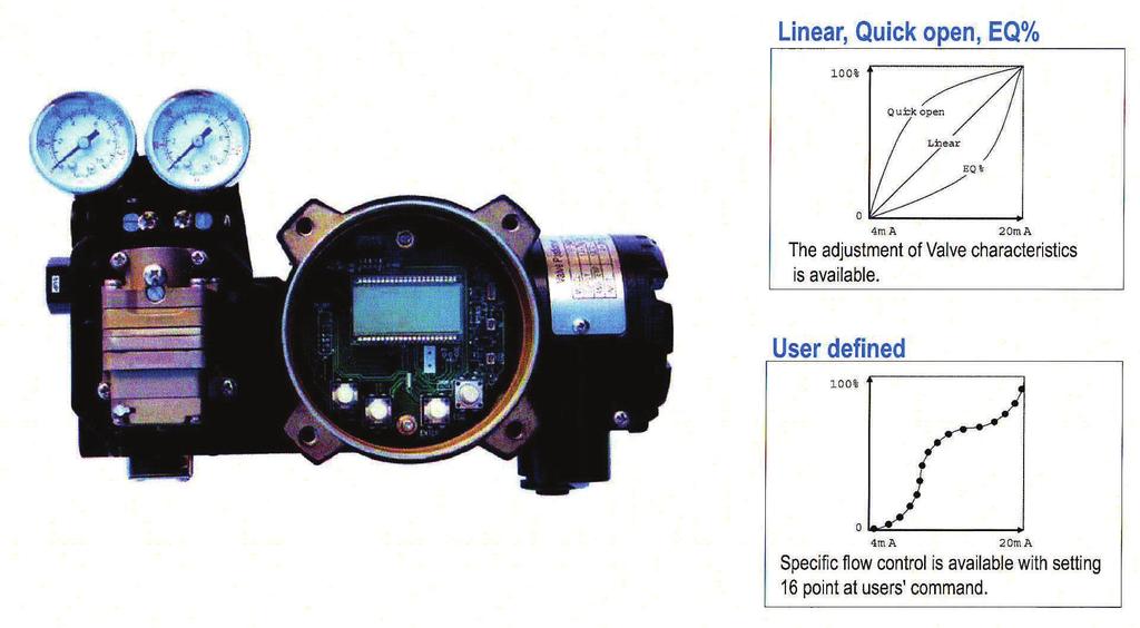
3 FEATURES and FUNCTIONS 1. There are four buttons on the outside of the positioner which allows for adjustment of parameters and menus without opening the cover in explosive gas areas. 2. The smart positioner is ExdIIBT6 explosion proof rated. 3. Endures severe vibration. 4. The pilot relay valve is installed on the outside of the positioner body, which allows for easy serviceability. 5. It operates normally regardless of the change in supply pressure during operation. 6. This positioner is easy to auto-calibrate. 7. Its compact size allows for easy installation on small actuators. 8. Plant operating costs may be reduced due to its low air consumption. 15. Specific flow control is available with 16 specified user points. 16. Tight shut-off and open can be set by the user. 17. Regulated filtered air flows to the actuator by using the A/M switch. 18. Split range input is 4-20mA, 12-20mA. 19. The Hand Calibration function can be used to set zero and span. 20.The positioner has a self diagnose function for greater reliability. 21. It is equipped with a manual override. 22. The protection class is IP The epoxy powder coating allows for long periods of exposure to a corrosive environment. 24. Very easy to maintain with its modular design. 9. Due to the low voltage (8.5V) usage, there is no limitations with the controller. 10. An adjustable orifice is used to accommodate small actuators so control is optimized during operation. 4~20 ma INPUT (10-30V) Feed Back Signal V+ OUT V- V+ OUT V- Limit Limit Limit Switch Circuit V+ OUT OUT Voltage load Circuit V- 11.The valve positioner has HART communication capability. Detecting Limit Load Out Voltage 12. The positioner output uses an analog feedback system. 13. An alarm function is available when using a limit switch. 14. Available valve flow characteristics are linear, quick opening, and equal percent. 3


4 STRUCTURE The structure of the YT-2400L is as follows. The YT-2400R is the same as the linear type except for the feedback lever. Pilot Relay Cover Button Cover Body Cover Pilot Relay Potentiometer Main PCB Variable Orifice Manifold Main Shaft Piezo Filter Plug Terminal Cover Base Body Terminal Plate Feedback Spring Flange Nut Feedback Lever YT-2400L (Linear Type) YT-2400R (Rotary Type) 4


5 FEATURES & FUNCTIONS 5
6 INSTALLATION NOTE: When the positioner is installed or replaced with the actuator, ensure the following: 6 WARNING: To avoid damage to the process system or personal injury, isolate the valve from the system and relieve any pressure contained within prior to disassembly. Disconnect any operating lines providing air pressure, control signals, or electrical power to the actuator TOOLS FOR INSTALLATION Tools and bolts used for assembly are: 1. Hexagonal wrenches 2. (+) screw driver 3. (-) screw driver 4. Spanners for hexagon head bolts YT-2400L Installation YT-2400L is used for linear motion valves such as globe valves or gate valves using spring return type diaphragm actuators or piston actuators. YT-2400L consists of the following components. Be sure that all the components are prepared M8 TAP YT-2400 body 2. Feedback lever and spring lever 3. Flange nut (attached on the body of the main shaft of the YT-2400L body) 4. 4 pcs of hexagon head bolt M8x1.25P 5. 4 pcs of M8 plate washer YT-2400L Drawing YT-2400R Drawing YT-2400 Installation Example M3 TAP
 YT-2400L feedback lever should be level at 50% of the valve stroke (Refer to point #7) B) Feedback lever connection bar of the")
 If the bracket meets the above conditions, installation of the YT-2400L is simple. Installation of the actuator clamp and connection bar 5.")
7 Installing YT-2400L with Bracket 1. It is necessary to make a proper bracket to attach onto the actuator yoke. The most important notes in making the bracket are as follows: A) YT-2400L feedback lever should be level at 50% of the valve stroke (Refer to point #7) B) Feedback lever connection bar of the actuator clamp should be connected at the position that the valve and stroke numbers engraved on the feedback lever match. (Refer to point #8) If the bracket meets the above conditions, installation of the YT-2400L is simple. Installation of the actuator clamp and connection bar 5. Temporarily connect the air filter regulator to the actuator temporarily. Set the supply pressure of the air filter regulator to ensure that the actuator clamp is positioned at 50% of the valve stroke. 2. Assemble the YT-2400L and bracket with supplied bolts. Installing YT-2400L with Bracket Connection of supply pressure pipe between the actuator and air filter regulator 6. Insert connection bar attached on the actuator clamp into the slot of the YT-2400 feedback lever. Ensure the connection bar looks like the diagram below in order to reduce hysterisis. 3. After assembling the YT-2400L attach it using the bolt holes of the actuator yoke. Do not tighten bolts completely - there must be some space remaining. 4. Install the bar connected to the YT-2400 feedback lever on the actuator clamp. The slot length between the YT-2400L feedback lever is 6.5mm, so the diameter of the connection bar should be less than 6.3mm. The connection bar inserted correctly between the feedback lever and lever spring 7

8 90% 7. Ensure the YT-2400L feedback lever is level at 50% of the valve stroke. If not, make it level by moving the bracket of feedback link bar. If the YT-2400 is installed and not level at 50% of the valve stroke, product linearity becomes worse. No Touch Feedback lever being leveled correctly 50% Check whether or not the lever stopper and feedback lever is contacted 9. If the YT-2400L is installed correctly as shown in the above procedures, tighten the nuts and bolts on the bracket and feedback lever connection bar. YT-2400R Installation 8. Check the valve stroke. The numbers indicating stroke are engraved on the YT-2400L feedback lever. Set the connection bar attached on the actuator clamp on the number so the feedback lever is applicable to the valve stroke as shown in the following picture. YT-2400R is used for a rotary motion valve such as a ball or butterfly valve using rack and pinion, scotch yoke or complex type actuators whose stem is rotated 90 degrees. YT-2400R consists of the following components: Stroke 30mm Stroke 70mm 1. YT-2400R main body 2. Fork spring & lever attach onto the actuator 3. 1 set of brackets 4. 4pcs of Hexagon head bolt M8x1.25P 5. 4pcs of M8 plate washer YT-2400R Installation Example Installation position of the connection bar for the valve stroke NOTE: After installation, operate the valve from 0% stroke to 100% when using the air filter regulator on the actuator. When the stroke is both at 0% and 100%, the feedback lever should not reach the lever stoppers on the backside of the YT If the feedback lever reaches the lever stopper, move the attachment position of the YT-2400L to the direction becoming more distant from the yoke center. 8 YT-2400R Installation example of fork lever YT-2400R Installation example of NAMUR shaft

9 Installing YT-2400R with Bracket The YT-2400R is supplied with a standard bracket. The bracket consists of 2 parts and can be used with a fork lever and NAMUR shaft. The bracket is assembled in the factory based on 20mm of actuator stem height. If the actuator stem height exceeds 20mm, such as 30mm, or 50mm, reassemble the bracket adjusting to the height. Referring to the following table, check the hole positions Upper Bracket A 2. Attach the bracketed YT-2400R to the actuator by using the supplied bolts. The size of the bracket hole is 6mm. When tightening the bolts, use the spring washer or similar washer for firm attachment to the actuator. The direction of the bracket is different from the operating condition, but normal direction is shown in the following picture. So that, when the piping of the actuator and YT-2400R is in direction A, the bracket hole and indicator attached on the bottom of the YT-2400R main shaft should be the same direction as the half circle. H: 50 H: 30 H: H: 20 H: 30 H: A-L A-R H: 20,30 H: H: 50 H: 20, B-L B-R Upper Bracket B Direction A Bracket Assembly method by actuator stem height H Actuator Stem Height (H) Markings of Bolt Holes A-L B-L A-R B-R 20mm H: 20 H: 20, 30 H: 20 H: 20, mm H: 30 H: 20, 30 H: 30 H: 20, mm H: 50 H: 50 H: 50 H:50 Ex: In case that H is 30mm, A-L should be locked in H:30 hole B-L in H: 20,30; A-R in H:30, B-R in H:20, 30 with bolts. 1. In general, the height of an actuator (H) is 20, 30, or 50mm. After checking (H), assemble brackets as explained in the previous paragraph. The bracket is set as 20mm type in the factory. 20 Actuator Stem Actuator Actuator Stem Height (H=20mm) Attachment Direction of bracket and Actuator 3. Set the rotation position of the actuator stem at the initial zero point which is stroke 0%. In the case of the spring return type actuator, the actuator stem is always rotated at zero point without supply pressure, it is easy to check zero point. If the actuator is double acting, check whether it is clockwise or counter-clockwise or the rotation direction of the actuator stem with using supply pressure. 4. Set the actuator stem at the initial zero point and install the fork lever as in the following picture. Ensure the position of the initial zero point when the actuator stem is clockwise or counter-clockwise. Installation angle of the fork lever should be 45 degrees based on the linear shaft, but the angle is not related to the NAMUR shaft. 9


10 45 Counter-clockwise Connection Shaft Clamping Pin 45 Fork Lever Clockwise Fitting the pin on the YT-2400R main shaft into the fork lever hole. Installation position of the fork lever 5. If the fork lever position is set, check lock nuts assembled on the bottom of the fork lever when turning clockwise. Set the upper height of the fork lever as 6-11mm lower than the brackets upper height. 7. Fix the YT-2400R base and the bracket with the hexagon head bolts and plate washer. It is better to lock the bracket and YT-2400R after checking the position of the YT-2400R by inserting four bolts. Bracket 6-11 mm Fork Lever Actuator Height of bracket, fork and fork lever 6. Attach the YT-2400R to the bracket. Fix the clamping pin on the main shaft center of the YT-2400R into the hole of the fork lever and insert the connection bar attached on the main shaft lever into the fork lever slot to be locked. This is to fit the main shaft of the YT-2400R and the center of the actuator stem. If they are not fitted correctly, the product durability is reduced due to excess force on the main shaft of the YT-2400R. Assembly status of the YT-2400R. PIPING CONNECTION NOTE: -To prevent moisture, oil and dust from getting inside the product, give careful consideration to the choice of supply pressure compressor and its system. -We recommend to attach filter or air filter regulator in front of the supply port of the YT-2400R. 10
. 5. Not to be used beyond the range of 1.4-7 kgf/cm 2 (140-700 kpa). 6. Set air filter regulator s supplied pressure 10% higher than actuator s spring range pressure. Pipe Condition 1.")
11 Supply Pressure Condition 1. Dry air with at least 10 C lower than ambient temperature. 2. Keep away from dusty air. The filter is for 5 microns or larger. 3. Avoid oil. 4. Comply with ANSI/ISA (R1981). 5. Not to be used beyond the range of kgf/cm 2 ( kpa). 6. Set air filter regulator s supplied pressure 10% higher than actuator s spring range pressure. Pipe Condition 1. Make sure inside of pipe is empty. 2. Do not use pipeline that is squeezed or has holes. 3. To maintain flow rate, use the pipeline that has more than 6mm inner diameter. 4. Do not use an extremely long pipeline system. It may affect flow rate due to the friction inside the pipeline. Piping Connection with Actuator YT-2400 series single acting type is set out to use OUT1 port. OUT1 port should be connected with the supply pressure port from the actuator when using single acting type spring return actuator. Double Acting Actuator In the case of the YT-2400 series, double acting type, when inserting current signal, supply pressure is from OUT1 port. Piping connection example of the YT-2400L with double acting actuator. Piping connection example of the YT-2400R with double acting actuator. POWER CONNECTION 1. In hazardous areas like explosive gas areas, conduit tube or pressure-proof packing union must be used. In case of pressure-proof packing union, use the cable that has appropriate outer diameter, considering inner rubber packing size. And in case of the conduit tube, ensure that it is fully sealed with using gaskets or sealing materials. Explosion Protected Nipple Compound Charging Box (Flameproof Type Sealing Fitting) Union Conduit Tube Insert Wire Pressure Proof Packing union Conduit Tube Piping connection example of YT-2400R with single acting actuator. 2. Conduit entry size is PF 1/2 or G 1/2. 11

12 3. When the power is connected, do not open the cover. Confirm that the power is shut down before opening the cover. Ensure that there is no remaining current voltage. 4. Use an approved flexible cable to protect against vibration, impact, and, tension. 5. If the position transmitter or limit switch is installed,12-24vdc power should be additionally supplied to each switch. Ensure not to exceed the maximum 30VDC. 6. For product protection, ground with the ground terminal on terminal box or PCB plate. 7. Use a ring type wire terminal to prevent vibration or impact. 8. Do not install the cable near the equipment such as a high capacity transformer or motor generating noise. 9. Use shielded cable to protect against noise. Terminal Connection of Current Impact Signal 1. Loosen bolts of terminal box cover with a 3mm wrench. 2.Open the cover by turning counter-clockwise by grabbing the terminal box cover or using a driver head. 3. There are two entries on the right bottom of the YT When connecting power, a pressureproof packing union or conduit tube can be used. Choose an approved connection type considering explosion proof and installation conditions. 4. The terminal of the current input signal is on the bottom left of the terminal plate, as in the following picture. Insert terminal bolts in cable terminal holes and lock them with a (+) terminal and (-) terminal each on the terminal plate. Refer to the following diagram. 5. Ensure not to change the polarity of the terminal. 6. Set the terminal cover box with the terminal box and turn clockwise until the bolts are tightened. 7. Lock the locking bolts of the terminal box cover clockwise using a 3mm wrench. Terminal Plate Position ~ IN+: Current Input Signal (+) ~ IN-: Current Input Signal (-) ~ OUT+: Feedback Signal (+) ~ OUT-: Feedback Signal (-) Connection Position of Current input signal terminal ~ Top 3 terminals on second row : stroke 0% limit switch ~Bottom 3 terminals on second row: stroke 100% limit switch Terminal Connection of the Feedback Signal 1. Loosen the bolts of the terminal box cover with a 3mm wrench. 2. Open the cover by turning counter-clockwise by grabbing the terminal box cover or using the driver head. 3. There are two entries on the right bottom of the YT When connecting power, a pressure-proof packing union or conduit tube can be used. Choose an approved connection type considering explosion proof and installation conditions. 4. The terminal of the current input signal is on the bottom left of the entire terminal plate, as in the following picture. Insert terminal bolts in cable terminal holes and lock them with a (+) terminal and (-) terminal each on the terminal plate. Refer to the following diagram. 12

13 5. Ensure not to change the polarity of the terminal. 6. Set the terminal cover box with the terminal box and tighten the bolts. 7. Lock the bolts of the terminal box cover clockwise while using a 3mm wrench. 5. Ensure not to change the polarity of the terminal. 6. Install the terminal cover with the terminal box and tighten the bolts. 7. Tighten the bolts of the terminal cover with a 3mm wrench. 8. The adjustment of RA and DA is done by moving the dip switch on the right of the terminal plate. (+) terminal (-) terminal Limit Switch Circuit V+ load Com Circuit Out Voltage V- Terminal Connection Transmitter Detecting Limit Load Out Voltage LED Terminal Connection of Limit Switch Terminal Connection of Limit Switch 1. Loosen the bolts of the terminal box cover with a 3mm wrench. 2.Open the cover by turning counter-clockwise by grabbing the terminal box cover or using a driver head. 3. There are two entries on the right bottom of the YT When connecting power, a pressureproof packing union or conduit tube can be used. Choose an approved connection type considering explosion proof and installation conditions. 4. Limit switch terminals are at the top of the terminal plate as shown in the following picture. The top three terminals on the right is the valves 0% position and the three terminal on the bottom is the valves 100% position. Insert the terminal bolts into the cable ring terminal holes and lock them with a (+) and (-) terminal on the terminal plate. Terminal Connection for Ground 1. The ground connection is necessary for the safety of the YT-2400 and its system. 2. The inside terminal is on the right bottom of the terminal plate and the outside terminal is beside the outer cable entry. Use any ground terminal when available and resistance must be less than 100 ohm. 3. When using an inside ground, loosen ground bolts. Insert outside ground bolts and spring washer into the ring type terminal of the cable ground and tighten them with bolts. 4. When using an outside ground, loosen the bolts of the terminal box cover with a 3mm wrench. 5. Open the cover by turning counter-clockwise by grabbing the terminal box cover or using a driver head. 13


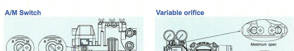
14 6. There are two entries on the right bottom of the YT When connecting power a pressureproof packing union or conduit tube can be used. Choose an approved connection type considering explosion proof and installation conditions. 7. Inside ground terminals are at the bottom of the terminal plate as shown in the following picture. There are two terminals on the right, both terminals can be used. Choose a suitable connection type considering explosion proof and installation conditions and insert cable ground into the terminal box. 8. Tighten the bolts of the terminal cover to with a 3mm wrench. 2. Turn the switch clockwise and supply pressure of the air filter regulator is transmitted to the actuator. 3. If turning the switch counter-clockwise, the YT-2400 is operated normally. AUTO MANUAL Adjustment of A/M Switch Variable Orifice Ground Out Ground Out If the actuator volume is too small, hunting may occur. In this case, adjust the variable orifice using a slot screw driver, then hunting will be prevented by reducing the flow rate of supply pressure to the actuator. Ground Terminal Connection Maximum Open Minimum open ~ Maximum open the direction of the screw slot is parallel with the indicator arrow on both ports. ~Minimum open The direction of the screw slot is perpendicular to the indicator arrow on both ports. A/M SWITCH - (AUTO/MANUAL SWITCH) There is an A/M switch on the bottom of the YT If this switch is set as auto, supply pressure is transmitted to the actuator by the operation of the YT If it is set as manual, supply pressure of the air filter regulator is transmitted to the actuator regardless of the YT * When the A/M switch is set as manual, ensure that too much pressure is not transmitted to the actuator. 1. Ensure the supply pressure of the air filter regulator is correct. AUTO CALIBRATION & BASIC OPERATIONS WARNING: Since this makes the valve or actuator move, before auto calibration, the valve must be disconnected from the entire system. Button Adjustment of Variable Orifice The YT-2400 series performs various functions using four buttons. 14

15 The shape and position of buttons are as follows: <>: To return to the previous menu <Enter>: To go to the main menu, save adjusted parameter values or choose sub menus. <DOWN>: To move to another menu or change parameter values. <UP>: To move to another menu or change parameter values. Run Mode After connecting power to the YT-2400, the following is displayed on LCD in 6 seconds. Run Mode The Buttons of the YT-2400 Run on the bottom line means that the YT-2400 adjusts the valve stroke when receiving an outside signal (4-20mA) and PV means the number on the LCD. In RUN mode, the valve stroke is changed according to the input signal. There are six types displayed in RUN mode. In order to change the display, push <> and <UP> at the same time. Whenever pushing the buttons, the display is changed in that order. If pushing <> and <DOWN> simultaneously, the order is opposite and if only pushing <>, display is returned to RUN mode. PV Currently displayed on LCD (1) Run PV Process Value First Auto Calibration Valve Stroke (%) (2) Run SV% Set Value Input Signal (0-100%) (3) Run SV ma Set Value Input Signal (4-20mA) (4) Run MV Manipulate Value Motor Controlled Variable (Digit) (5) Run Vel Velocity Current Valve Speed (Digit) (6) Run Err Error Difference between SV and PV % The first auto calibration is usually used when the YT-2400 has not been set, this occurs when the initial setting of the valve at the valve company or replacement with other products in the field. In this case, entire parameters are set by using AUTO2 calibration. WARNING: When the YT-2400 is installed on the valve in the field, after setting, we recommend that you use AUTO1 Calibration rather than AUTO2. This allows optimum parameters set by the valve company and it is better if those parameters are not changed by AUTO1 calibration. 1. Connect power. Any values between 4-30mA (DC) can be used for power. After connecting power READY 6, 5, 4, 3, 2, 1 message appears on the LCD, in order, that indicates the start time to operate the PCB unit and parts. The following message is displayed in 6 seconds. Push <ENTER> for 6 sec. at RUN mode and AUTO CAL message appears. 15
16 2. Push <ENTER> and AUTO1 mode is started. 3. Push <DOWN> and AUTO2 mode is displayed. 4. Push <ENTER> at AUTO2 mode. Auto 2 calibration is started and the next modes are displayed in order on the LCD. Normally it takes 3-5 minutes for auto calibration in AUTO2 mode, but it can differ depending on the actuator volume and other factors, such as conditions. 5. When auto calibration is done COMPLETE message appears on the LCD. After 4 seconds the procedure is returned to RUN mode and the valve stroke by current input signal is displayed as a percentage. 6. Zero, Span, PID parameters and RA/DA are automatically set when Auto 2 calibration is complete. ZERO POINT END POINT KP / KI / KD Auto Calibration Types Auto 1 Calibration (AUTO1) BIAS V_O RA / DA AUTO 1 O O X O O O AUTO 2 O O O O O O AUTO 3 X X O O O O BIAS X X X O X X V_O X X X X O X In this mode all parameters necessary for valve operation are set except KP, KI, and KD. It is used to re-execute calibration by users in the field after being supplied a YT-2400 whose parameters were set by a valve company. 1. Keep pushing <ENTER> for 6 seconds. 2. Push <ENTER> 3. Push <DOWN> 1. Push <ENTER> for 6 seconds at RUN mode and an AUTO CAL message will appear. 2. Push <ENTER> and then AUTO1 mode is displayed. 4. Push <ENTER> 5. Complete RUN MODE Entire Modes and Functions *Auto calibration = (AUTO CAL) The calibration of the YT-2400 is simply performed by auto calibration and there are 5 types of auto calibration as AUTO1, AUTO2, AUTO3, BIAS, V_0. 3. Push <ENTER> again at AUTO1 mode and Auto1 calibration is started. 4. When Auto calibration is done, COMPLETE message will appear. After 4 seconds, the procedure is returned to RUN mode and the valve stroke by current input signal is displayed as a percentage. AUTO1 calibration is useful for users in the field and AUTO2 is for valve companies or setting the initial parameters of the YT AUTO1, AUTO2, AUTO3 calibration set RA/DA automatically. 1. Keep pushing <ENTER> for 6 seconds 2. Push <ENTER> 3. Push <ENTER> 5. Completed 6. RUN MODE after 4 seconds. 16
17 Auto 2 Callibration (AUTO2) All parameters necessary to operate the valve are set. The calibration is used when the YT-2400 is first installed with the valve. Refer to the section on first auto calibration. Auto 3 Calibration (AUTO3) All parameters necessary to operate the valve are set except zero and end point. This function is used to re-execute auto calibration without changing zero and the end point after manually adjusting them. 1. Push <DOWN> at AUTO2 and AUTO3 is displayed. 2. Push <ENTER> and AUTO3 calibration is started. The next procedure of this calibration is the same as the other calibrations. BIAS Calibrations BIAS means standard value of motor control that is used in the positioner. It is affected by supply pressure, KP and other values, therefore it should be re-adjusted if supply pressure or KP is changed. Unless the value is correctly set, accuracy can be very low. 1. Push <DOWN> at AUTO3 mode and BIAS mode is displayed. 2. Push <ENTER> and BIAS calibration is started. The next procedure of this calibration is the same as the other calibrations. Velocity Calibrations (V_0) This is the function to find the standard value to recognize accurate valve speed. Unless this value is correctly set, KI control can be slower or impossible. In order to check if this value is accurately set, push <> at RUN mode and RUN Vel is displayed. At this time the number on the bottom line of the LCD indicated the value close to zero. (After the valve is stopped) Usually the number is between 2 and 2. If the number is over 5, execute this function again and reset the V_0 value. 1. Push <DOWN> at BIAS mode and V_0 mode is displayed. 2. Push <ENTER> and V_0 calibration is started. The next procedure of this calibration is the same as the other calibrations. Manual Mode Manual mode is used to raise or lower the valve stem manually. In this mode valve stroke is adjusted only by operating buttons, not by the current input signal. This mode doesn't affect controlling data registered in the YT-2400 and only moves the valve stem up & down. 1. Keep pushing <ENTER> at RUN mode and the AUTO CAL message is displayed. 2. Push <DOWN> and MANUAL MODE is displayed. 3. Push <ENTER> again. Two lines on the LCD are displayed. The upper one indicates valve stroke by percentage and the lower one indicates the absolute value of inner resistance of the YT *MA indicates manual mode is in operation. 4. Push <UP> or <DOWN> and the valve stem moves up or down. Regardless of RA or DA, if you push <UP>, the valve stem moves up (in case of linear valve) and if you push <DOWN> the valve stem moves down. In order to make the valve stem move faster, push <ENTER> with <UP> and <DOWN>. Push <UP> Push <UP> + <ENTER> at the same time Push <DOWN> Push <DOWN> + <ENTER> at the same time Valve stem moves up slowly Valve stem moves up quickly Valve stem moves down slowly Valve stem moves down quickly 17
18 5. Push <> and MANUAL MODE is displayed. KI This is an integral constant value, adding or subtracting the correction that is correcting by Error % on the previous correction signal. If this value is too high, there can be oscillation. If it is too low, the time to find the exact position is longer. KD Parameter Mode (PARAM) With auto calibration, optimum operation is available for most actuator control. But if the optimum operation is difficult because of hunting or oscillation, it can be solved by PID parameters and DeadZone. Parameter Types There are four types of parameters: Dead Zone, KD, KP, & KI. These values are reflected as soon as they are changed, therefore the appropriate values are found when checking the valves motion in real time. Dead Zone (deadzone) This is the section of Error % that the control is not operated. If there is hunting or oscillation continuously due to the friction between stem and packing, they are prevented with this parameter. KP This is the proportion constant value of correction that is correcting the Error %. If this value is too high, there can be hunting to find its position by input signal. If the value is too low, accuracy gets worse. This is a differential constant value adding previous correction signal when changing correction signal by Error % change rate. If this value is too high, there can be hunting. If this value is too low, dynamic characteristics during the time to find the position get worse. Adjustment of Parameter Dead Zone (deadzone) (1) Push <ENTER> at RUN mode for 6 seconds and AUTO CAL message apprears. (2) Push <DOWN> twice and PARAM mode is displayed. (3) Push <ENTER> and deadzone mode is displayed. (4) Push <ENTER> again and *EAdZONE message appears. (5) Adjust deadzone value by <UP> or <DOWN>. Adjusted value is applied right away without additional operation, so users can easily check its adjustment by changing the current input signal to YT It means that optimum control value is found by adjusting values during valve operation. (6) Push <ENTER> to save the value. +EAdZONE message is on LCD. (7) Push <> three times to return to RUN mode. 18
19 KP (1) - (3) Adjustment method and procedure is the same as the deadzone. (4) Push <DOWN> at deadzone mode and KP mode is displayed. (5) Push <ENTER> and *KP message is on LCD. (6) Adjust KP values with <UP> or <DOWN>. Adjusted value is applied right away without additional operation, so users can easily check its adjustment by changing the current input signal to YT It means that optimum control value is found by adjusting values during valve operation. (7) Push <ENTER> to save the value. +KP message is on the LCD. (8) Push <> (9) Push <> twice to return to RUN mode. KI (1) - (3) Adjustment method and procedure is the same as the deadzone. (4) Push <DOWN> at deadzone mode and KI mode is displayed. (4) Push <DOWN> at deadzone mode and KI mode is displayed. (5) Push <ENTER> and *KI message is on LCD. (6) Adjust KI values with <UP> or <DOWN>. Adjusted value is applied right away without additional operation, so users can easily check its adjustment by changing the current input signal to YT It means that optimum control value is found by adjusting values during valve operation. (7) Push <ENTER> to save the value. +KI message is on the LCD. (8) Push <> (9) Push <> twice to return to RUN mode. KD (1) - (3) Adjustment method and procedure is the same as the deadzone. (4) Push <DOWN> at deadzone mode and KD mode is displayed. (5) Push <ENTER> and *KD message is on LCD. (6) Adjust KP values with <UP> or <DOWN>. Adjusted value is applied right away without additional operation, so users can easily check its adjustment by changing the current input signal to YT It means that optimum control value is found by adjusting values during valve operation. (7) Push <ENTER> to save the value. +KD message is on the LCD. (8) Push <> (9) Push <> twice to return to RUN mode. 19
20 HAND CAL When auto calibration is started YT-2400 sets zero point and end point based on a full stroke. But when there is a necessity of re-adjusting zero and end points to a specific section in an entire stroke. Hand calibration is used, and both the valve and transmitter can be re-adjusted. Hand Calibration Types: PV_ZERO: Edit mode to change the zero point of valve. PV_END: Edit mode to change the end point of valve. TR-ZERO: Edit mode to change the zero point of transmitter. TR_END: Edit mode to change the end point of transmitter. On the LCD valve stroke is displayed as 0%. *PZ message indicating edit mode of zero point and inner value showing current zero point position are also displayed. 4. Adjust valve stem while pushing <UP>, <DOWN>. When valve stem is at the desirable zero point, save it with <ENTER>. +PZ message is appeared on LCD. 5. Push <> at this mode to return PV_ZERO mode. (Push <> twice at this mode to return to RUN mode) 6. In order to change valve end point, push <DOWN> at PV_ZERO mode and PV+_END mode is started. 7. Push <ENTER> at PV_END mode and *PE mode is displayed. In this mode it is possible to change the valve end point and the valve stem moves automatically to the current end point. On the LCD the valve stroke is displayed at 100%. *PE message indicating edit mode of end point and inner value of end point are also displayed. 8. Adjust valve stem with using <UP> or <DOWN>. When the valve stem arrives at a desirable end point, save it with <ENTER>. +PE message is appeared on the LCD. 9. Push <> to return to PV_END mode. 10. Push <> twice and RUN mode is displayed.(push <DOWN> at PV_END mode to go to TR_ZERO mode) Adjustment of valve zero point ((1)-(5)) and end point ((6)-(10)) 1. Push <ENTER> at RUN mode for 6 seconds and then AUTO CAL mode is displayed. Push <DOWN> three times, then HAND CAL mode is displayed. 2. Push <ENTER> at HAND CAL mode and PV_ZERO mode is started. 3. Push <ENTER> at PV_ZERO mode and *PZ mode is started. In this mode it is possible to change valve zero point and valve stem moves automatically to current zero point. 20
21 Adjustment of zero point ((1)-(4)), end point ((5)-(9)) of transmitter. If valve zero point and end point are changed, the transmitter is also changed automatically. So usually there is no need for the transmitter zero point and end point to be adjusted by users, but if the transmitter output signal is unstable, transmitter zero point and end point should be adjusted. The ammeter showing feedback signal is necessary and the connection should be done as in the following picture. 7. Adjust the measured current value to be 20mA on ammeter with <UP> or <DOWN>. Push <ENTER> to save it. +R_END message appears. 8. Push <>. TR_END mode is displayed. 9. Push <> twice at this mode to return to RUN mode. 1. Push <DOWN> at PV_END mode and then TR_ZERO mode is displayed. 2. Push <ENTER>. *R_ZERO mode is started and in this mode users can adjust zero point of transmitter. Valve stem is moved to zero point automatically. 3. Push <UP> or <DOWN>. The number on the above on the LCD is changed and the measured current value is changed accordingly to the ammeter. Adjust it to be 4mA and push <ENTER> to save it. +R_ZERO message appears. 4. Push <>. TR_ZERO mode is displayed. 5. Push <DOWN> at TR_ZERO mode. Then TR_END mode is displayed. (Push <> twice to return to RUN mode) 6. Push <ENTER>. *TR_END mode is started and in this mode users can adjust the end point of the transmitter. The valve stem is moved to end point automatically. Valve Mode: This mode is to adjust the various characteristics. Action Type (ACT): It sets direct action (DA) and reverse action (RA). Characteristics (CHAR): It sets characteristics. There are 3 types of valve characteristics, which are Linear (LIN), Equal percent (EQ), and Quick Open (QO). The following is an example of the 3 characteristic curves. Stroke 21
22 User Characteristics (USER SET): When a specific characteristic which is not included in the above characteristics is needed, it is possible to make a specific characteristic curve by choosing 16 points voluntarily according to field conditions and users need. Adjustment of Characteristics (CHAR): 1. Push <ENTER> at VALVE mode and then push <DOWN>. CHAR LIN (in case of linear characteristic) mode is displayed. 2. Push <ENTER>. *HAR LIN mode is displayed and characteristics can be adjusted at this mode. Tight Shut Open (TSHUT OP): This is to press down the valve fully at any valve around 20mA current input signal. Tight Shut Close (TSHUT CL): This is to close valve completely at setting value around 4mA input signal from outside. Split Range Control (SPLIT): This is to control the entire stroke by 3 input signals of 4-20mA, 4-12mA and 12-20mA. Adjustment of Acting Type (ACT): 1. Push <ENTER> at RUN mode for 6 seconds and then AUTO CAL mode is displayed. Push <DOWN> 4 times to go into VALVE mode. 2. Push <ENTER> and ACT RA (in case of RA) is displayed. 3. Push <ENTER> again, then *ACT RA is displayed. 4. Adjust to *ACT DA by pushing <UP> or <DOWN> and save it by pushing <ENTER>. +ACT DFA message is on. 5. Push <> 3 times to return to RUN mode. 3. Adjust characteristics (ex: EQ) by pushing <UP> or <DOWN> and save by pushing <ENTER>. +HAR EQ is displayed. 4. Push <> 3 times to return to RUN mode. Adjustment of User Characteristics (USER SET): 1. Push <ENTER> at VALVE mode and ACT RA or ACT DA is displayed. 2. Push <DOWN> twice, then USER SET mode is started. 3. Push <ENTER>. *P0 SET mode is displayed and at this mode users can adjust the first point of characteristic in 16 points. The number on the LCD is the valve stroke percentage set to P0. 4. Adjust valve stroke percentage by pushing <UP> or <DOWN>. 5. Save it by pushing <ENTER>. While P0 value is being saved, *P1 SET mode is displayed. 6. *P1 SET mode is to adjust the second point of characteristic in 16 points. Adjustment method is the same as *P1 SET mode. 7. Save valve stroke percentage from P2 to P15 in the same way. 8. After adjustment of valve stroke percentage at *P15 SET mode, save it with <ENTER>. 9. +SER SET is displayed. Total 16 points of valve stroke percentage are all set. Push <> 3 times to return to RUN mode. 22
23 Adjustment of Tight Shut Open (TSHUT OP): 1. Push <ENTER> at VALVE mode and ACT RA or ACT DA is displayed. Push <DOWN> 3 times at this mode, then TSHUT OP is displayed. 2. Push <ENTER> *SHUT OP mode is displayed and in this mode users can set the stroke at the time of Tight Open. Initial setting is done at 100%, which means cancellation of this function. Adjust the value (ex: 95.0%) by pushing <UP> or <DOWN> and save it by pushing <ENTER>. +SHUT OP is displayed. 3. Push <> 3 times to return to RUN mode. Adjustment of Tight Shut Close (TSHUT CL): 1. Push <ENTER> at VALVE mode and ACT RA or ACT DA is displayed. Push <DOWN> 4 times at this mode, then TSHUT CL is displayed. 2. Push <ENTER> *SHUT CL mode is displayed and in this mode users can set the stroke at the time of Tight Close. Initial setting is done at 0.3%. 0% which means cancellation of this function. Adjust the value (ex: 0.5%) by pushing <UP> or <DOWN> and save it by pushing <ENTER>. +SHUT CL is displayed. 3. Push <> 3 times to return to RUN mode. Adjustment of Split Range (SPLIT): 1. Push <ENTER> at VALVE mode and ACT RA or ACT DA is displayed. 2. Push <DOWN> 5 times and SPLIT mode is displayed. The numbers on the LCD is the range of the current signal input to the YT mA current signal is set as the standard. 3. Push <ENTER> *SPLIT mode is displayed and input signal range can be adjusted. Adjust signal range by pushing <UP> or <DOWN> and save it by pushing <ENTER>. 4. +SPLIT mode is displayed while saving the adjusted range. Push <> 3 times to return to RUN mode. VIEW mode: This mode provides users with various information about the YT And in this mode users can change the valve stroke types displayed on the LCD as % or numbers. Refer to the next table for information and description displayed on VIEW mode. 1. Push <DOWN> at AUTO CAL mode and VIEW mode is displayed. 2. Push <ENTER> at VIEW mode then the information mode is started. 3. Check information by pushing <UP> or <DOWN> and push <>. 4. Push <> again to return to RUN mode. 23
24 Information Checked on View Mode DRIPTION YT-2400L Product Model Version Main Software Version HART V HART Protocol Version POL AddR Channel Address used in HART protocol bias V 0Y 0d FULL_OP FULL_CL VM NOR Erro VALUE 1 BIAS valve necessary to motor control (This variable is only used by the manufacturer.) Total using time But if the product is used less than one minute from power-on to power off it is not added to total time. Full Open Time ( Sec.) of valve Full Close Time (Sec.) of valve Display type of valve stroke on LCD Error or warning code currently occurred Refer to the code table Currently controlled 1 value (This variable is only used by the manufacturer) Error and Warning Code: If there are problems during YT-2400 operation you can check the error and warning code at VIEW mode as follows. Error code: This code is displayed when YT-2400 control gets impossible and code C, D is applied. Warning Code: This code is displayed when YT-2400 control is unavailable but there is possibility of a malfunction or low accuracy. Code B, F,G, H, is applied. 24
25 Error / Warning Code Code Description and Cause Measures A None None B C D The range of Pv Span - Pv Zero is less than 500. > Operating angle of feedback is too small. More than 10% error is continued over 1 minute. > There is no valve movement. > Valve friction is getting larger. > Regulator pressure setting has changed. I value is at 1 max. or min. limit. > Valve friction has changed > Regulator pressure setting has changed. >Adjust operating angle of feedback lever to be bigger and execute AUTO 1 Calibration. > Check the setting pressure of the air filter regulator. Adjust it to the recommended pressure, and execute BIAS calibration. > Check the setting pressure of the air filter regulator. Adjust it to the recommended pressure, and execute BIAS calibration. E None None F Full open - close time is less than one second. > Actuator size is too small. G Pv is set below 100. >Operating angle of the feedback lever is too large. H Pv is over > Operating angle of the feedback lever is too large. > Use variable orifice. > Replace actuator to larger one. > Adjust operating angle of feedback lever to be smaller, and execute AUTO 1 calibration. > Adjust operating angle of feedback lever to be smaller, and execute AUTO 1 calibration. 25
26 Firmware MAP Error Code View Method Full Close Time : Up Button : Down Button KD Full Open Time ENT : Button : Enter Button KI User Set Used Time V_0 KP Split Control I Value BIAS KD TR End Point Tight Shut-on BIAS AUTO 3 KI TR Start Point Tight shut-off Polling Ad. AUTO 2 KP End Point Character HART Ver. AUTO 1 Dead Zone Start Point RA/DA Sol Ver. ENT ENT ENT ENT ENT AUTO CAL Manual Mode Parameter Hand Cal Valve View (5 Sec) RUN MODE 26
27 NOTES strives for the highest levels of quality and accuracy. The information included in this publication is presented for informational purposes only. reserves the right to modify or change, and improve design, process, and specifications without written notice. Under no circumstance is the information contained to be interpreted to be a guarantee/warranty with regard to our products or services, applicability or use. Selection, use and maintenance are the sole responsibility of the end user and purchaser. CVS Controls assumes no liability for the selection use and maintenance of any product. 27
28 Head Office Street Edmonton, Alberta, Canada T6E 0A5 Office: (780) Fax: (780) Calgary Sales Office 205, Avenue NE Calgary, Alberta, Canada T2E 6Z3 Office: (403) Fax: (403) Website: Rev. 1 02/09 28
Series 185/285 Smart Positioners
 Series 185/285 Smart Positioners Bulletin V-185/285 Specifications - Installation and Operating Instructions DOUBLE ACTION SINGLE ACTION LCD SCREEN SMART POSITIONER 3-47/64 [95.00] Series 185 3-27/32 [97.50]
Installation- Linear. I & M Mark 17X Series. Mark 17X Linear Installation
 I & M Mark 17X Series 3170 Wasson Road Cincinnati, OH 45209 Phone 513.533.5600 Fax 513.871.0105 (f) info@richardsind.com www.jordanvalve.com Installation & Maintenance Instructions for the Mark 17X Series
INSTRUCTION MANUAL. CVS Series 3400 Flameproof Smart Positioner. Introduction
 INSTRUCTION MANUAL CVS Series 3400 Flameproof Smart Positioner Introduction The CVS 3400 is a CSA approved and Explosion Proof Rated EX d IIC T6/T5, Class 1, Zone 1, Group A. Additional certifications
SMART POSITIONER YT-2400 SERIES USER'S MANUAL
 SMART POSITIONER YT-2400 SERIES USER'S MANUAL YTC V.1.02 1 Table of Contents Contents Page No. Introduction 4 Manufacturer Warranty 4 Product Description 5 Main Features and Functions 5 Label Description
SMART POSITIONER YT-3400 SERIES
 SMART POSITIONER YT-3400 SERIES USER'S MANUAL 1 V.1.02 Table of Contents Introduction 4 Manufacturer Warranty 4 Product Description 5 Main Features and Functions 5 Label Description 6 Suffix Symbol 7 Specification
SMART POSITIONER YT-3300/3301 SERIES
 SMART POSITIONER YT-3300/3301 SERIES PRODUCT MANUAL VERSION 1.02 Contents 1. Introduction 5 1.1 General information for the users. 5 1.2 Manufacturer Warranty 5 2. Product Description.. 6 2.1 General..
SMART POSITIONER SS3400 SERIES
 SMART POSITIONER SS3400 SERIES PRODUCT MANUAL VERSION 1.03 Contents 1. Introduction 4 1.1 General information for the users. 4 1.2 Manufacturer Warranty 4 1.3 Explosion Proof Warning. 3 2. Product Description..
SMART POSITIONER YT-2500/2501/2550 SERIES
 SMART POSITIONER YT-2500/2501/2550 SERIES PRODUCT MANUAL VERSION 1.03 Contents 1. Introduction 5 1.1 General information for the users. 5 1.2 Manufacturer Warranty 5 2. Product Description.. 6 2.1 General..
SMART POSITIONER YT-2300 SERIES USER'S MANUAL
 SMART POSITIONER YT-2300 SERIES USER'S MANUAL Table of Contents Contents Page No. Introduction 4 Manufacturer Warranty 4 Product Description 5 Main Features and Functions 5 Label Description 6 Suffix Symbols
SMART POSITIONER YT-2500 SERIES USER'S MANUAL
 SMART POSITIONER YT-2500 SERIES USER'S MANUAL YTC V.1.01 1 Table of Contents Introduction 4 Manufacturer Warranty 4 Product Description 5 Main Features and Functions 5 Label Description 6 Suffix Symbol
SMART POSITIONER 6000/6050 SERIES
 SMART POSITIONER 6000/6050 SERIES PRODUCT MANUAL VERSION 1.00 Contents 1. Introduction 5 1.1 General information for the users. 5 1.2 Manufacturer Warranty 5 2. Product Description.. 6 2.1 General.. 6
SMART POSITIONER YT-2500/2550 SERIES USER'S MANUAL
 SMART POSITIONER YT-2500/2550 SERIES USER'S MANUAL YTC 1 V.1.04 Table of Contents Introduction 4 Manufacturer Warranty 4 Product Description 5 Main Features and Functions 5 Label Description 6 Suffix Symbol
SMART POSITIONER YT-3400 / 3450 SERIES PRODUCT MANUAL
 SMART POSITIONER YT-3400 / 3450 SERIES PRODUCT MANUAL VERSION 1.03 Contents 1. Introduction 4 1.1 General information for the users. 4 1.2 Manufacturer Warranty 4 1.3 Explosion Proof Warning. 3 2. Product
Series 60. New Smart Positioner. Compact design Convenient & powerful function Enhanced reliability
 Series 60 New Smart Positioner Compact design Convenient & powerful function Enhanced reliability J Flow Controls, LLC 14 De Camp Cincinnati, OH 45216 Phone: 513-731-2900 Fax 513-731-6939 www.jflowcontrols.com
TMP-3000 VERSION 1.01
 VERSION 1.01 Contents 1. Introduction... 4 1.1 General Information for the users... 4 1.2 Safety precautions and Manufacturer Warranty... 4 2. Product Description... 5 2.1 General... 5 2.2 Main Features
Smart Positioner YT-2400L,R Installation manual
 Installation Safety Warning When installing a positioner, please ensure to read and follow safety instruction. All input and supply pressure to valve, actuator, and other related devices must be turned
Pneumatic-Pneumatic Positioner YT-1200L,R Installation manual
 Installation Safety Warning When installing a positioned, please ensure to read and follow safety instruction. All input and supply pressure to valve, actuator, and other related devices must be turned
YT-2600 SERIES VERSION 1.07
 SMART POSITIONER YT-2600 SERIES PRODUCT MANUAL VERSION 1.07 Contents 1. Introduction... 4 1.1 General Information for the users... 4 1.2 Manufacturer Warranty... 4 1.3 Explosion Proof Warning & Specific
User s Manual. Pneumatic Positioner. Series 58. J Flow. Series 58. J Flow
 Pneumatic Positioner Series 58 User s Manual J Flow Series 58 J Flow Series 58 J Flow Controls, LLC 14 De Camp Cincinnati, OH 45216 Phone: 513-731-2900 Fax 513-731-6939 www.jflowcontrols.com Introduction
YT-2500 / 2550 / 2501 SERIES
 SMART POSITIONER YT-2500 / 2550 / 2501 SERIES PRODUCT MANUAL VERSION 1.10 Contents 1. Introduction... 5 1.1 General Information for the users... 5 1.2 Manufacturer Warranty... 5 1.3 Explosion Proof Warning
Pneumatic Positioner PNY Series USER'S MANUAL. Max-Air Technology. Version 1.0
 USER'S MANUAL Max-Air Technology Version 1.0 Table of Contents Introduction 3 Manufacturer Warranty 3 Product Description 4 Main Features and Functions 4 Operation Logic 4 Specification 5 Parts and Assembly
Electro-Pneumatic Positioner YT-1000 / 1050 SERIES
 Electro-Pneumatic Positioner YT-1000 / 1050 SERIES PRODUCT MANUAL VERSION 1.01 Contents 1. Introduction 4 1.1 General information for the users. 4 1.2 Manufacturer Warranty 4 1.3 Explosion Proof Warning.
Electro-Pneumatic Positioner YT-1000 / 1050 SERIES
 Electro-Pneumatic Positioner YT-1000 / 1050 SERIES PRODUCT MANUAL VERSION 1.01 Contents 1. Introduction 4 1.1 General information for the users. 4 1.2 Manufacturer Warranty 4 1.3 Explosion Proof Warning.
SS3 Linear / Rotary. Smart Valve Positioner. Smart performance with innovative and ever-strong coil drive even under harsh working environments
 Smart Valve Positioner SS3 Linear / Rotary Smart performance with innovative and ever-strong coil drive even under harsh working environments Easy and quick auto-calibration Detecting RA (reverse acting)
RTX1000 SERIES ELECTRO-PNEUMATIC POSITIONER
 RTX1000 SERIES ELECTRO-PNEUMATIC POSITIONER Installation Operation and Maintenance Manual RTX-IOM-RTX1000/1000L-R01-0416 Page 1 of 26 Contents 1. Introduction... 4 1.1. General information... 4 1.2. Definitions...
Pneumatic Positioner RTX - Series USER S MANUAL. ROTEX P/P Ver. 0.1 Dated: MAY / 2009 REV 01: SEP/2010 Page 1 of 16
 Pneumatic Positioner RTX - Series USER S MANUAL MODEL RTX 1200 AMBIENT TEMP. 20 C ~ 70 C WEATHER PROOF IP 65 SUPPLY PR. 1.4 ~ 7.0 bar INPUT SIGNAL 0.2 ~ 1.0 bar SERIAL NO. ROTEX P/P Ver. 0.1 Dated MAY
YT-1200 Series VERSION 1.02
 YT-1200 Series PRODUCT MANUAL VERSION 1.02 Contents 1. Introduction... 4 1.1 General Information for the users... 4 1.2 Manufacturer Warranty... 4 1.3 Explosion Proof Warning (Only for external explosion
YT-3300 / 3350 / 3303 / 3301 SERIES
 SMART POSITIONER YT-3300 / 3350 / 3303 / 3301 SERIES PRODUCT MANUAL YT-3300 YT-3300 with limit switch YT-3350 YT-3303 YT-3303 YT-3301 VERSION 1.11 Contents 1. Introduction... 5 1.1 General Information
TOP-QUALITY PNEUMATIC ACTUATOR
 TOP-QUALITY PNEUMATIC ACTUATOR BS EN ISO 9001:2000 INTRODUCTION PDS series Pneumatic Actuators are designed using Scotch-Yoke technology from PDS 50 to the largest of PDS 200. Scotch-Yoke technology is
AP ATEX AIRPOWER POSITIONERS AP2000 FEATURES AP1000 & AP1200 FEATURES OPTIONS OPTIONS
 AP1000-2000 Airpower positioners are a robust range of rotary or linear valve positioners in AP1000 electro-pneumatic (4-20mA), AP1200 pneumatic (3-15 psi) or AP2000 programmable smart type. Designed to
Electro-Pneumatic Linear Positioner Installation and Operation Instructions B GB
 Installation and Operation Instructions 99.66.02-B GB Description of Device (4-~20mA) is the advanced control device for a linear control valve that provides unparalleled stability in difficult environments
Installation and Operating Instructions Electro-Pneumatic Rotary Positioner SP-21. Description of Device. Part Number System
 Description of Device VALMAC Posi-Zest SP-2100 Series is the advanced control device for a rotary control valve that provides unparalleled stability in difficult environments. Easy Maintenance Precise
SS2 Linear / Rotary Smart Valve Positioner
 COTROLS A Division of AT Controls Smart performance with innovative and ever-strong coil drive even under harsh working environments Also available in REMOTE TYPE 316 STAILESS STEEL BODY Smart performance
CVS Rack and Pinion Pneumatic Actuator
 Instruction Manual CVS Rack and Pinion Pneumatic Actuator Introduction These instructions apply specifically to the CVS Rack and Pinion pneumatic actuator. This manual provides sizing, maintenance, operation,
INSTRUCTION MANUAL. CVS P32 LP Gas Reducing Regulator
 INSTRUCTION MANUAL CVS P32 LP Gas Reducing Regulator The CVS Controls P32 Regulator is a non-relieving, pressure reducing regulator suitable for use in lower flow, LP gas applications (Natural Gas and
POSITIONERS and Controls for Complete Valve Automation
 CONTROLS A Division of AT Controls Pneumatic & Electro-Pneumatic POSITIONERS and Controls for Complete Valve Automation 1 SS SERIES SS Features Easy and quick auto-calibration Detecting RA (reverse acting)
Instruction and Operating Manual
 M/SS2/E 01 2011 Instruction and Operating Manual Smart Valve Positioner SS2L / SS2R Series Contents 1. Introduction 2 11.5 Sub-Parameters Flow Diagram 2. Overview of Structure 3 11.5.1 Change of Input
SP-20 Input. Installation and Operating Instructions Electro-Pneumatic Linear Positioner. Description of Device. Part Number System
 Description of Device VALMAC Posi-Zest SP-2000 Series is the advanced control device for a linear control valve that provides unparalleled stability in difficult environments. Easy maintenance Precise
Smart Valve Positioner. TS800Series. Instruction Manual
 Smart Valve Positioner TS800Series Instruction Manual Ver. PM-TS800EN-8/2017 Table of Contents 1 Introduction------------------------------------------------------------------------------------- 4 1.1
Fig Single-Acting Rotary Smart Positioner
 Fig. 3303 Single-Acting Rotary Smart Positioner Order Information Model No. EC03303RSN52000S Econ series 3300 Smart Positioner for quarter turn actuators in single acting version. This positioner regulates
CVS Series 35, 50, 60, 70. Scotch Yoke Hydraulic Actuators. Introduction. Instruction Manual
 Instruction Manual Figure 1: CVS Series 35 SRM100 Actuator CVS Series 35, 50, 60, 70 Scotch Yoke Hydraulic Actuators Introduction The CVS Hydraulic Actuator uses a scotch yoke mechanism to convert linear
CVS 7970 High-Low Pressure Pilot
 Instruction Manual CVS 7970 High-Low Pressure Pilot Introduction This instruction manual includes the following information for CVS 7970 High-Low Pressure Pilot: 1. Description 2. Piston Arrangement Changeover
Type Installation, Operation and Maintenance Instructions. Ordering Information. Contents CA20 -
 Type 2000 Pneumatic and Electropneumatic Valve Positioner Installation, Operation and Maintenance Instructions Ordering Information Use this coding system to order Model CA20 - Type of Positioner 00 P/P
Electro-Pneumatic Positioner RTX - Series USER S MANUAL. ROTEX E/P Ver. 0.1 Dated: dd / mm / yy Page 1 of 18
 Electro-Pneumatic Positioner RTX - Series USER S MANUAL ROTEX E/P Ver. 0.1 Dated dd / mm / yy Page 1 of 18-1 - RTX1000-R2-2011 Table of Contents Introduction 3 Manufacturer Warranty 3 General Service Information
Moniteur INSTALLATION & OPERATING INSTRUCTIONS. SERIES 40 Positioners. Installation and Operating Instructions Series 40 Positioners.
 INSTALLATION & OPERATING INSTRUCTIONS SERIES 40 Positioners Form IO2-0406 Description of Device Moniteur's Series 40 pneumatic (3-15psi) and electropneumatic (4-20mA) positioners are advanced control devices
Mounting and operating instructions EB 5801 EN. Electric Actuators Type 5801 (Rotary Actuator) Type 5802 (Linear Actuator)
 Type 5802 (Linear Actuator)") Electric Actuators Type 5801 (Rotary Actuator) Type 5802 (Linear Actuator) Linear Actuator with Type 3260 Control Valve Rotary actuator with lever system Linear actuator with Type 3321 (V2001) Control
Electric Actuators Type 5801 (Rotary Actuator) Type 5802 (Linear Actuator) Linear Actuator with Type 3260 Control Valve Rotary actuator with lever system Linear actuator with Type 3321 (V2001) Control
Operation Manual Electro-Pneumatic Positioner Model: NT-1000R (Rotary Type) NUTORK CORPORATION
 NUTORK CORPORATION") Operation Manual Electro-Pneumatic Positioner Model: NT-1000R (Rotary Type) Integral Mounted Air Set Dome Indicator NUTORK CORPORATION Table of Contents Introduction 2 Manufacturer Warranty Product Description
Operation Manual Electro-Pneumatic Positioner Model: NT-1000R (Rotary Type) Integral Mounted Air Set Dome Indicator NUTORK CORPORATION Table of Contents Introduction 2 Manufacturer Warranty Product Description
TECHNICAL BULLETIN. Logix 510si Series Digital Positioner. Experience In Motion FCD LGENTB /09
 Logix 510si Series Digital Positioner TECHNICAL BULLETIN FCD LGENTB0510-01 09/09 Experience In Motion Introduction The Logix 510si series are single acting, user-friendly digital positioners. As all positioners
Jordan Control Valve Series
 Jordan Control Valve Series Control Valves A control valve is used to manipulate flowing fluids like, gas, water, steam or process solutions. It compensates for changes in flow or pressure and regulates
YT-1000 / 1050 Series
 YT-1000 / 1050 Series PRODUCT MANUAL VERSION 1.07 Contents 1. Introduction... 5 1.1 General Information for the users... 5 1.2 Manufacturer Warranty... 5 1.3 Explosion Proof Warning (Only for explosion
EB EN. Type 3372 Electropneumatic Actuator. Translation of original instructions
 EB 8313-1 EN Translation of original instructions V2001-IP Control Valve Type 3372 0511/0531 Electropneumatic Actuator with Type 3321 Valve Type 3372 Electropneumatic Actuator Edition July 2013 Note on
Pneumatic or Electropneumatic Positioner for Rotary Actuators Type Fig. 1 Type 3761 Positioner. Mounting and Operating Instructions EB 8386 EN
 Pneumatic or Electropneumatic Positioner for Rotary Actuators Type 3761 Fig. 1 Type 3761 Positioner Mounting and Operating Instructions EB 8386 EN Edition June 2004 Contents Contents Page 1 Design and
Operating Instructions. Pneumatic Control Valve Low Temperature. Type Series GS3
 Operating Instructions Pneumatic Control Valve Low Temperature Type 8026 Series GS3 With: Digital Positioner Type 8048 Electro-pneumatic Positioner Type 8047 Pneumatic Positioner Type 8047 Version: 03/2006
Type 3761 Pneumatic or Electropneumatic Positioner for Rotary Actuators. Fig. 1 Type 3761 Positioner. Mounting and Operating Instructions EB 8386 EN
 Type 3761 Pneumatic or Electropneumatic Positioner for Rotary Actuators Fig. 1 Type 3761 Positioner Mounting and Operating Instructions EB 8386 EN Edition July 2007 Contents Contents Page 1 Design and
Positioners Converters Limit Switches Position Transmitters Solenoid Valves Accessories. Selection and Application
 Positioners Converters Limit Switches Position Transmitters Solenoid Valves Accessories Selection and Application Associated s T 8355 EN ff. Edition January 2010 Information Sheet T 8350 EN Positioners,
Automation is the techniques and equipment used to achieve automatic operation or control.
 VALVE AUTOMATION What is Automation? Automation is the techniques and equipment used to achieve automatic operation or control. Automation is an automatic operation and control of machinery or processes
TOP-QUALITY PNEUMATIC ACTUATOR
 TOPQUALITY PNEUMATIC ACTUATOR BS EN ISO 9001:2000 INTRODUCTION PDS series Pneumatic Actuars are designed using ScotchYoke technology from PDS 50 the largest of PDS 200. ScotchYoke technology is well known
Accord Logix Series 1000 Digital Positioner
 Accord GENERAL INFORMATION The following instructions are designed to assist in unpacking, installing and performing maintenance as required on Logix Series 1000 Digital Positioners. Series 1000 is the
Electro-Pneumatic Positioner Series 830/831-WP/EX. Operation & Maintenance Manual
 Electro-Pneumatic Positioner Series 830/831-WP/EX Operation & Maintenance Manual Electro-Pneumatic Positioner Model 830/831- WP/EXP This operation & maintenance manual corresponds to Forbes Marshall Arca
VPA Series and VAP Actuator
 VPA Series and VAP Actuator PN6 Flanged Pressure Independent Balancing and Control Valve Product Bulletin PB_VPA_06 204 VPA Pressure Independent Control Valve is a combination of a differential pressure
Instruction Manual. CVS Series H-900, H-1500 and H-2500 Design Valve Bodies. Contents. Figure 1: Typical CVS Series H Design Body with Trim and Seals
 Instruction Manual CVS Series H-900, H-1500 and H-2500 Design Valve Bodies Contents Contained in this manual are installation instructions, maintenance procedures and parts information for the CVS Series
PP Series Pneumatic Actuators
 PDF Published February 4, 07 PP Series Pneumatic Actuators for Chemline ball valves up to 6 MATERIAL: Polyamide SERIES: PPS Spring Return PPD Double Acting CONTROL PRESSURE: 40 to 0 psi OUTPUT TORQUES:
Damper Actuator Installation
 FANs 268.1, 977, 1628.3 Installation Bulletin EPP-1000 Issue Date 0800 EPP-1000 Series Electro-Pneumatic Positioners A pplication The EPP-1000 is designed for applications where electronic control of pneumatic
Installation, Operation and Maintenance Manual
 HQ 005. ELECTRIC ACTUATORS QUARTER-TURN ELECTRIC ACTUATORS Installation, Operation and Maintenance Manual s Version Ver. 1 Revision Rev. 1 Document No. HKQI-611 Small & Compact Design High corrosion resistance
Product Manual. CVS Series D Globe and Series DA Angle Style Valves. Introduction. Applications and Features
 Product Manual CVS Series D Globe and Series DA Angle Style Valves Introduction Contained in this manual are installation instructions, maintenance procedures and parts information for the -inch and 2-inch
TECHNICAL BULLETIN. Logix 520MD Series Digital Positioner. Experience In Motion FCD LGENTB /09
 Logix 520MD Series Digital Positioner TECHNICAL BULLETIN FCD LGENTB0520-01 11/09 Experience In Motion Introduction The Logix 520MD Series combines superior positioning and tuning functions with convenient
ESD Systems. CVS Controls Ltd is dedicated to providing you with the right Emergency Shut Down System to best suit your applications needs.
 ESD Systems CVS Controls Ltd is dedicated to providing you with the right Emergency Shut Down System to best suit your applications needs. A wide array of individual products to add to your current configurations,
ARCAPRO positioner. Positioner customized for specific tasks
 ARCAPRO ARCAPRO Positioner customized for specific tasks 2 3 1 A linear function between the input signal and stroke is the best way to ensure maximum control precision. Control valves with pneumatic actuators,
Instruction Manual. CVS Series E 1 through 6-Inch Globe Valves. Design ED and ET Introduction. Contents. Applications and Features
 Instruction Manual CVS Series E 1 through 6-Inch Globe Valves Design ED and ET Introduction Contents Contained in this manual are installation instructions, maintenance procedures and parts information
Device Description User Manual Logix MD+ Positioners with HART
 Device Description User Manual Logix MD+ Positioners with HART CONTENTS DD MENU CHART... 3 GENERAL INFORMATION... 6 INTRODUCTION... 6 QUALIFIED PERSONNEL... 6 USING THIS DOCUMENT... 6 TERMS CONCERNING
SMART VALVE POSITIONER 4 to 20 ma + HART Digital Communication. smar B87
 SMART VALVE POSITIONER to ma + HART Digital Communication B87 DESCRIPTION The FY microprocessor based positioner provides fast and accurate positioning of diaphragm or cylinder actuators. The FY produces
YT-720 SERIES. Rotork YTC Limited VERSION 1.07
 YT-720 SERIES PRODUCT MANUAL YT-720S YT-720D Rotork YTC Limited VERSION 1.07 Contents 1. Introduction... 3 1.1 General Information for the users... 3 1.2 Manufacturer Warranty... 3 1.3 Explosion Proof
LTX RF LEVEL SENSOR. Instruction Manual
 LTX RF LEVEL SENSOR Instruction Manual FOR MODELS LTX01, LTX02, LTX05 Intempco Document No: LTX - M01 Rev. 1 Issue Date: April 2005 LTX01 RF LEVEL SENSOR USER MANUAL Software Rev : Rev. Date : June 2004
CVS Type 667 Diaphragm Actuator Sizes 30-70
 Instruction Manual CVS Type 667 Diaphragm Actuator Sizes 30-70 All CVS Controls actuators are to be installed and maintained in accordance with instructions supplied by CVS Controls. This manual includes
CENTAC Inlet and Bypass Valve Positioners
 CENTAC Inlet and Bypass Valve Positioners INGERSOLL-RAND AIR COMPRESSORS INLET AND BYPASS VALVE POSITIONERS Copyright Notice Copyright 1992, 1999 Ingersoll-Rand Company THIS CONTENTS OF THIS MANUAL ARE
PG Series 180º Rotation Pneumatic Actuators
 PDF Published April 18, 2016 PG Series 180º Rotation Pneumatic Actuators for Chemline 3-way ball valves up to 4 material: Epoxy and Rilsan coated aluminum SERIES: PGS Spring Return PGD Double Acting control
Operating Instructions. Angle Seat Control Valve. Type 7020
 Operating Instructions Angle Seat Control Valve Type 7020 With: Digital Positioner Type 8048 Electro-pneumatic Positioner Type 8047 Pneumatic Positioner Type 8047 Version: 02/2006 Manual-7020e.doc Art.-No:
Installation & Operation Manual
 Installation & Operation Manual (I-TORK PDS Series Pneumatic Actuator) PDS-M0108/1010 74-6, Chun Ui-Dong, Won Mi-Gu, Bucheon, Kyoung Ki-Do, Korea Tel : 82-2-855-1365, 66 Fax : 82-2-855-1367 E-mail : roy75@i-tork.com
V200 Positioner. V200 P Pneumatic Positioner. V200 E Electropneumatic Positioner. Housing Material: Cast aluminium with polyester coating
 V200 Positioner Housing Material: Cast aluminium with polyester coating Indicator Options: Flat pointed indicator or raised indicator (red/green or yellow/black) One housing for pneumatic or electropneumatic
Terminator PICV. Technical Manual
 Terminator PICV Technical Manual Table of Contents Introduction 1 Advantages and Ease of Use 1 Applications examples 2 Technical specifications Start Up Charts 6 Start Up Charts 7 Start Up Charts 8 Flow
E-training. Positioners (Pneumatic, Electro pneumatic, I to P converters) Pneumatically actuated valves can be positioned in a number of ways.
 Pneumatically actuated valves can be positioned in a number of ways.") Welcome to the K Controls e-training course designed to deliver useful Pneumatic Valve Actuation application information in small instalments. To unsubscribe or to register a colleague to receive these
Welcome to the K Controls e-training course designed to deliver useful Pneumatic Valve Actuation application information in small instalments. To unsubscribe or to register a colleague to receive these
12 Series Linear Actuators. Operation & Maintenance Manual, Analog Positioner Installation
 12 Series Linear Actuators Operation & Maintenance Manual, Analog Positioner Installation 6810 POWERLINE DR.-FLORENCE, KY. 41042 - TELEPHONE 859-727-7890, TOLL FREE 1-800-662-9424 FAX. 859-727-4070, E-MAIL:
PRODUCTS CATALOG (2018) TISSIN CO.,LTD. Smart Valve Positioner. Electro-Pneumatic Positioner. Volume Booster. Lock Up Valve. Air Filter Regulator
 TISSIN CO.,LTD. Smart Valve Positioner. Electro-Pneumatic Positioner. Volume Booster. Lock Up Valve. Air Filter Regulator") PRODUCTS CATAOG (08) TISSIN CO.,TD. Smart Valve Positioner Electro-Pneumatic Positioner Volume Booster ock Up Valve Air Filter Regulator Solutions for control valve system About Tissin Solutions for control
PRODUCTS CATAOG (08) TISSIN CO.,TD. Smart Valve Positioner Electro-Pneumatic Positioner Volume Booster ock Up Valve Air Filter Regulator Solutions for control valve system About Tissin Solutions for control
User s Manual OM th edition
 FloWing Eccentric Rotary type Control Valves Model: VFR (1, 1½, 2 inches) User s Manual OM2-8130-0300 5th edition Copyright, Notices and Trademarks 2012 Azbil Corporation All Rights Reserved. While this
Type 2000 Transducer Product Instructions
 Type 2000 Transducer Product Instructions The Type 2000 is an electro-pneumatic device that regulates an unregulated supply pressure down to an electronically-controlled output pressure. There are two
Double Acting & Spring Return. SERIES 92/93 Rack & Pinion PNEUMATIC ACTUATOR. The High Performance Company
 PNEUMATIC ACTUATOR SERIES 92/93 Rack & Pinion Double Acting & Spring Return The High Performance Company SERIES 92/93 Styling, strength, compactness, and simplicity of design have been combined to produce
Python Series Control Valves
 Python - 1500 Series Control Valves Control valves are a key component in any pressure or temperature control application. With the increasing cost of fuel, delivering media in the most efficient way increases
Model DFR 070/156/220 Rotary Actuator
 Figure 1 DFR 156 TABLE OF CONTENTS General 2 Actuator Assembly 18 Scope 2 Bushing / Yoke Assembly 18 Principles of Operation 2 Spring Barrel Assembly 18 Safety Caution 2 Diaphragm Plate Assembly 20 Specifications
PP Series Pneumatic Actuators
 PDF Published September 9, 0 PP Series Pneumatic Actuators for Chemline ball valves up to 6 for Chemline butterfly valves up to 6 MATERIAL: Polyamide SERIES: PPS Spring Return PPD Double Acting CONTROL
AE Installation Operation & Maintenance Instructions
 AE-1400 Installation Operation & Maintenance Instructions IMPORTANT Please read the installation operation and maintenance instruction prior to using any Jomar Valve component. Failure to follow the instructions
Control Valves Positioner
 Control Valves Positioner HiFlo Valve Positioner Easy calibration Corrosion-resistant cover and base Withstands 150 psi at all parts Two -sided cam for easy field reversibility Optional / NPT for piped
Control Valves Positioner
 Control Valves Positioner HiFlo HiFlo Valve Positioner Corrosion-resistant cover and base Easy calibration Withstands 150 psi at all parts Two -sided cam for easy field reversibility Optional / NPT for
SAX Electronic Valve Actuator
 Document No. 129-561 SAX Electronic Valve Actuator Product Description The SAX Electronic Valve Actuator requires a 24 Vdc or 24 Vac, Class 2, supply signal to control a Flowrite 599 Series valve or a
SMART VALVE POSITIONER 4 to 20 ma + HART Digital Communication. smar
 SMART VALVE POSITIONER to ma + HART Digital Communication smar DESCRIPTION The FY microprocessor based positioner provides fast and accurate positioning of diaphragm or cylinder actuators. The FY produces
SECTION CONTROL VALVE ACTUATORS
 SECTION 23 09 13.34 - CONTROL VALVE ACTUATORS PART I GENERAL 1.0 OVERVIEW [Background for PSC] A. Control Valve/Actuator Applications 1. See Exhibit 23 09 13.33-1, Control Valve/Actuator Worksheet for
Fisher 2052 Diaphragm Rotary Actuator
 Instruction Manual 2052 Actuator Fisher 2052 Diaphragm Rotary Actuator Contents Introduction... 1 Scope of Manual... 1 Description... 1 Specifications... 4 Installation... 4 Actuator Mounting and Changing
Actuated Valves PRICING
 Electric & Pneumatic Actuated Valves Actuated Valves PRICING Page Suitable for Oil-Free air handling to 5 psi, not for distribution of compressed air or gas Spears Manufacturing Company Due to Material
OAKLEAF INVESTMENT HOLDINGS 52 (Pty) ltd
 ltd") REV. 04 04 14 OAKLEAF INVESTMENT HOLDINGS 52 (Pty) ltd is by contract the exclusive import agent and service provider in South Africa for various foreign specialist manufacturers of FIELD PROCESS MEASURING
REV. 04 04 14 OAKLEAF INVESTMENT HOLDINGS 52 (Pty) ltd is by contract the exclusive import agent and service provider in South Africa for various foreign specialist manufacturers of FIELD PROCESS MEASURING
MD50Y Intelligent Linear Actuator
 Product Sheet AT.00 Actuator Type MD50Y MD50Y Intelligent Linear Actuator The compact MD50Y is an intelligent modulating actuator that has an actuating force of 500 N. They can be used with two and three
ELECTRONIC CONTROL ACTUATOR
 ELECTRONIC CONTROL ACTUATOR Nucom Series LINEAR TYPE Nucom L100 OPERATION MANUAL Koei Industry Co., Ltd. FOR YOUR SAFETY In order for better and safety use of the product for a long period, please observe