Lesson 1 - Make The Car Move Points of this section
|
|
|
- Ethan Hawkins
- 6 years ago
- Views:
Transcription
1 Lesson 1 - Make The Car Move Points of this section Learning part: Learn how to use Arduino IDE Make the car move by uploading program Preparations: One car (with a battery) One USB cable
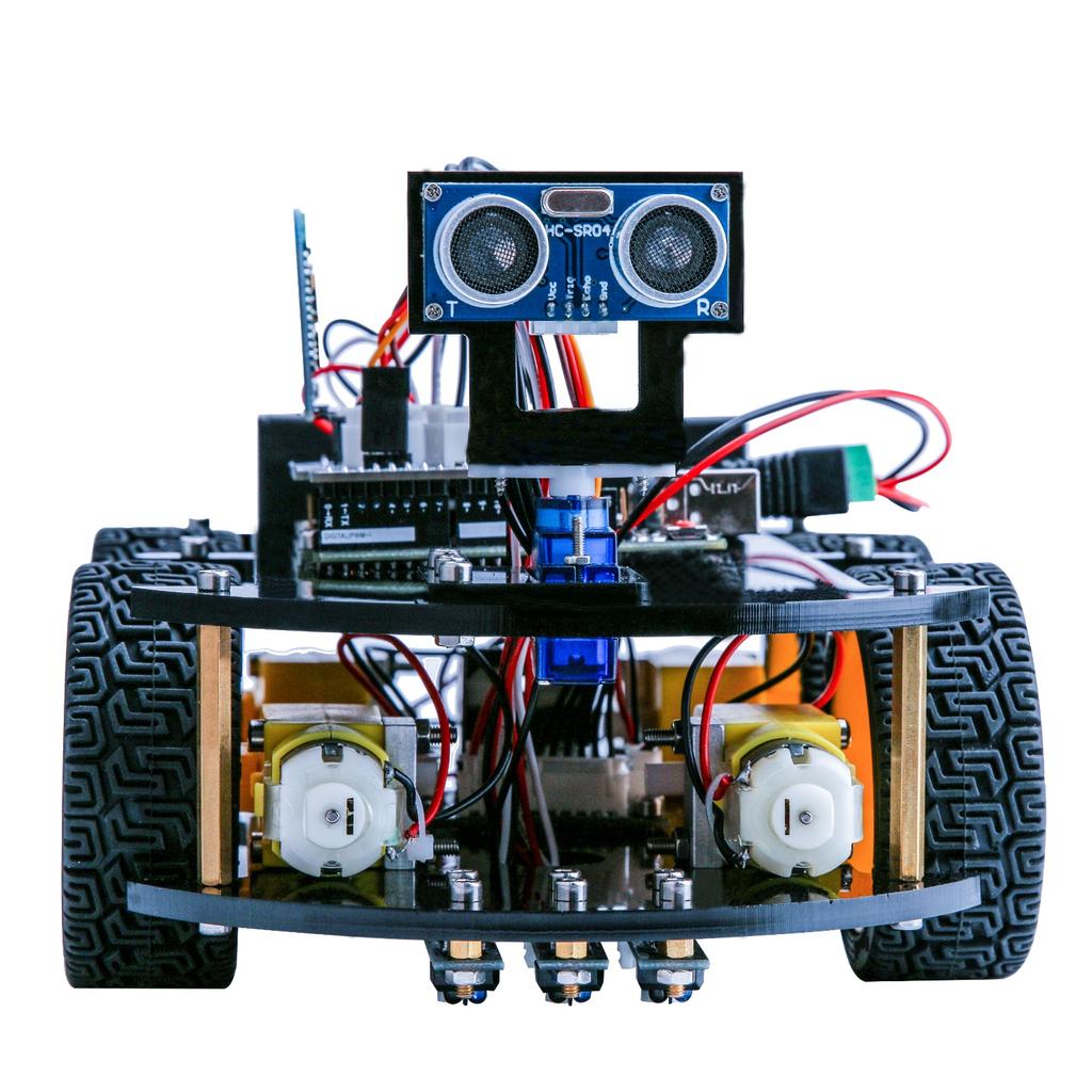
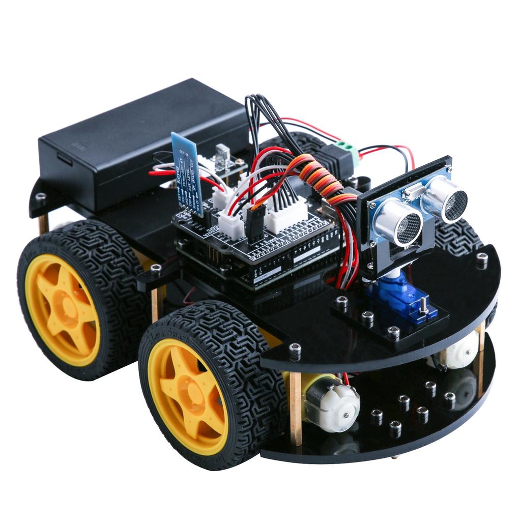
2 Ⅰ. Introduction of the car This kit is an extremely flexible vehicular kit particularly designed for education, competition and entertainment purposes. The upper panel of the kit is directly compatible with 9-gram steering engine. It also carries supersonic sensor, battery and other fixed holes to facilitate installation of various sensors. This is a very funny and versatile robot that meets learning and production purposes. With it, you can implement diverse interesting ideas, such as Bluetooth and infrared remote control, automatic avoidance of obstacles, and line inspection. Let s describe the small vehicle that will accompany us for a long time in the future.
3
4

5 Each parts of the car is as below:
6
7
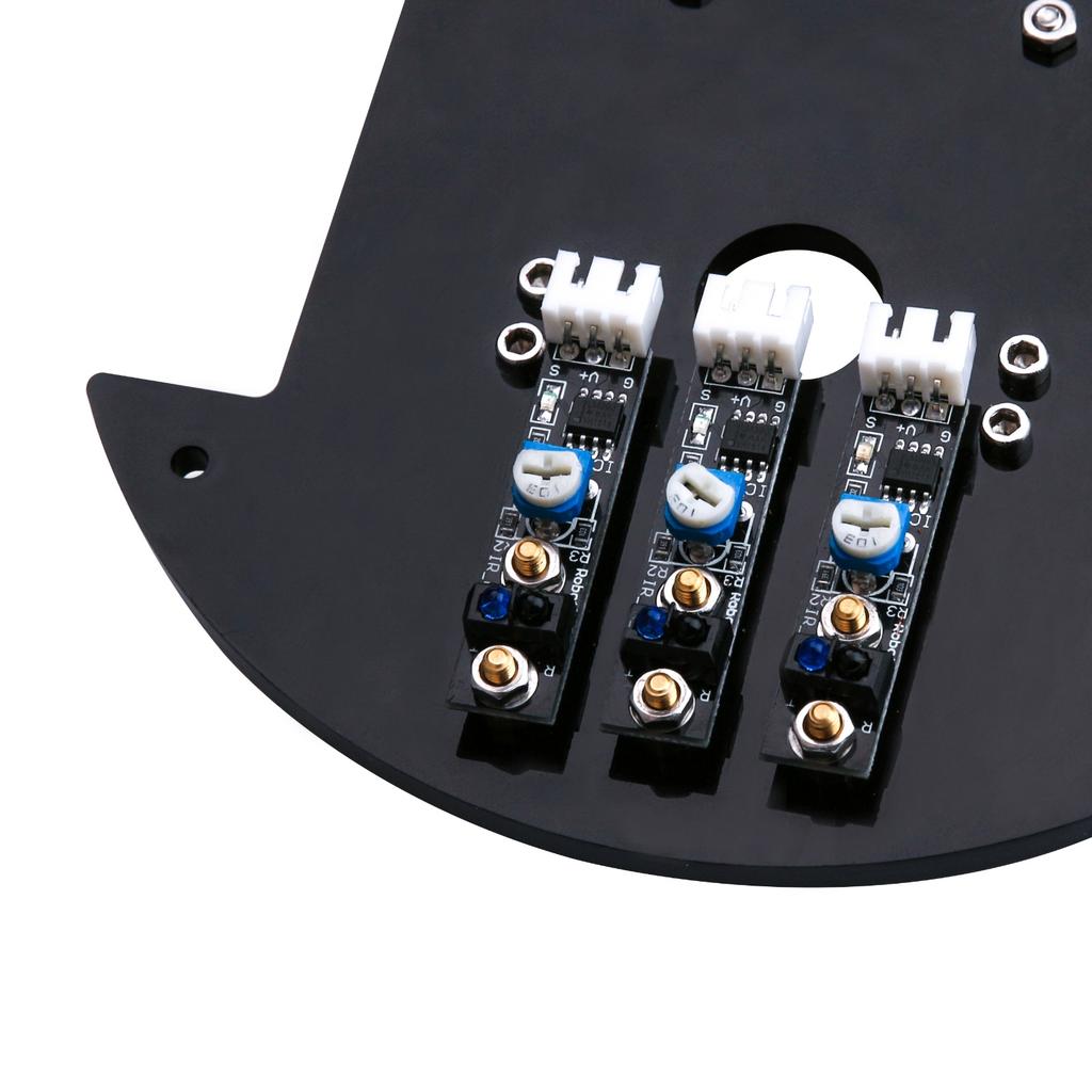
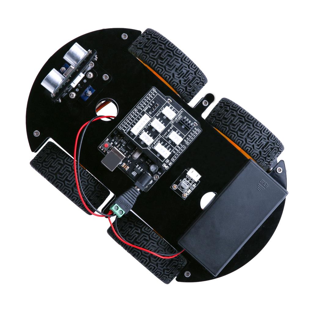
8 Function of each part: 1. Battery holder with a switch: provide power supply for the vehicle 2. Electric motor + wheel: drive the vehicle to move 3. acrylic plate: the frame of the car 4. L298N motor driving board: drive the motor to rotate 5. UNO controller board: the brain of the car, controls all the parts 6. V5 sensor expansion board: combined with the UNO, make the connection become more easier 7. Servo and cloud platform: enable the GP2Y0A21 distance sensor to rotate 180 degrees 8. Ultrasonic sensor module: distance measurement and obstacle avoidance 9. Line tracking module: black and white sensor for recognition of the white and black lanes 10. Infrared receiver and remote control: provide the infrared remote control function 11. Bluetooth module: provide the Bluetooth control function


9 Ⅱ. Upload program Each movement of the vehicle is controlled by the program so it s necessary to get the program installed and set up correctly. STEP 1: Go to and find below page. The version available at this website is usually the latest version, and the actual version may be newer than the version in the picture. STEP2:Download the development software that is suited for the operating system of your computer. Take Windows as an example here. You can install it using the EXE installation package or the green package. Press the button JUST DOWNLOAD to download the software.


10 These are available in the materials we provide, and the versions of our materials are the latest versions when this course was made. Choose I Agree to see the following interface Choose Next


11 Press Install to initiate installation Finally, the following interface appears, you should choose Install to ensure correctness of development Next, the following icon appears on the desktop

12 Double-click to enter the desired development environment

13 STEP3:Connect the car to the computer. STEP 4: Open IDE Tool Port. If you see the right port, it means that the vehicle has been connected correctly to the computer. In this case, you can jump to STEP 5 directly. Otherwise, you need to install the driver in the following way. Open Device Manager by right clicking My Computer Management Device Manager

14 Right click unknown device-----update device software It shows that the driver has not been installed, and you need to click Browse my computer for driver software to find the drivers. The drives is in the Arduino folder. Normally you will install the folder in C:\Program Files (x86)\arduino.
15 Arduino install folder

16 Select the Arduino driver folder Install Arduino USB device


17 STEP5: After the driver is installed, please open the IDE and then click Tools---Board--- Arduino/Genuino Uno
 STEP7:Open")

18 STEP6: Click Tools---Port---COMx (Arduino/Genuino Uno) STEP7:Open the file AUTO_GO_\AUTO_GO_.ino and upload to the UNO controller board
 The picture below shows that it is uploaded successfully. STEP8:Let s have a look at the results. Upload the program to the UNO controller board.")
19 Push the Button with arrow to upload program. (TIPS: The bluetooth module should be pulled out when you upload the program every time, or it will be failed to upload the program.) The picture below shows that it is uploaded successfully. STEP8:Let s have a look at the results. Upload the program to the UNO controller board. After disconnecting the car to the computer, you can turn on the power switch and put the car on the ground. Then you will see the car moving.
20 Ⅲ. Description of Principles motor UNO L298N motor driver board motor motor motor How to use L298N motor driver board Definition of the connection ports on L298N board have been marked above. The motors should be connected to the L298N board as the picture above, and if you find the rotational direction of one of the motors is opposite, please change the connecting position of its black and red wires. L298N GND is connected to battery box GND; L298N VCC is connected to battery box VCC; UNO board is also connected to battery box. L298N 5V here cannot be connected to UNO 5V; ENA and ENB control the speed of right motor and speed of left motor separately by PWM. IN1, IN2, IN3, IN4 : IN1 and IN2 are used to control right motor, IN3 and IN4 are used to control left motor. About the principle, please look at the sheet below: (We take right motor for example) ENA IN1 IN2 DC MOTOR STATUS O X X STOP 1 0 O BRAKING FORWARD BACKWARD BARKING
21 Ⅳ. Make The Car Move The first step: Drive the motor We will try to move the motor without speed controlling. Because it is easy to write program without speed controlling. First of all, let's see the connection of the motor the L298N board, we will use Arduino 5, 6, 7, 8, 9, 10 pins to control the car. 6 and 7 pins control the right wheel. 8 and 9 pins control the left wheel. 5 and 10 pins control ENA and ENB. So the connection is as below: L298N V5 expansion board ENA 5 IN1 6 IN2 7 IN3 8 IN4 9 ENB 11 Based on the sheet given above, we first design a simple program to make the right wheel turn 0.5s in positive direction, stop 0.5s, turn 0.5s in negative direction and stop 0.5s. And the wheel will repeat the reaction. Connect the UNO controller board to the computer, Open the file right_wheel_rotation\ right_wheel_rotation.ino Code is as follow: /*In1 connected to the 9 pin, In2 connected to the 8 pin, ENA pin 10,*/ int ENA=5; int IN1=6; int IN2=7; void setup() { pinmode(in1,output); pinmode(in2,output); pinmode(ena,output);
22 digitalwrite(ena,high); void loop() { digitalwrite(in1,high); digitalwrite(in2,low); //Right wheel forward delay(500); digitalwrite(in1,low); digitalwrite(in2,low); //Right wheel stop delay(500); digitalwrite(in1,low); digitalwrite(in2,high); //Right wheel back delay(500); digitalwrite(in1,low); digitalwrite(in2,low); //Right wheel stop delay(500); Upload the program to the UNO board, disconnect it from the computer, and then switch on the car s power supply. You will see that the right wheel moves as you expected. If the car is not moving, press the reset button on the UNO board. If the moving direction of the motor is different from the direction you set, you can change the connection of black and red lines from the motor to L298N board. Then, we make the left wheel rotate in the same way. Connect the UNO controller board to the computer, Open the file Left_wheel_rotation\ Left_wheel_rotation.ino Code is as follow: /*In3 connected to the 7 pin, In4 connected to the 6 pin, ENB pin 5,*/ int ENB=11; int IN3=8; int IN4=9; void setup()
23 { pinmode(in3,output); pinmode(in4,output); pinmode(enb,output); digitalwrite(enb,high); void loop() { digitalwrite(in3,low); digitalwrite(in4,high); //Left wheel forward delay(500); digitalwrite(in3,low); digitalwrite(in4,low); //Left wheel stop delay(500); digitalwrite(in3,high); digitalwrite(in4,low); //Left wheel back delay(500); digitalwrite(in3,low); digitalwrite(in4,low); //Left wheel stop delay(500); Upload the program to the UNO board, disconnect it from the computer, and then switch on the car s power supply. You will see that the right wheel moves as you expected. The second step: Move forward and backward After finishing debugging the car, you can write programs to make the car move. Below is the way how car moves: CAR forward back stop Left wheel Forward back stop Right wheel Forward back stop CAR Turn left Turn right stop Left wheel back Forward Stop Right wheel forward back stop Next, we will write a simple program to make the car go forward 0.5s, then stop 0.5s, 0.5s and then stop 0.5s. then back up
24 Connect the UNO controller board to the computer, Open the file forward_back\ forward_back.ino Code is as follow: int ENA=5; int IN1=6; int IN2=7; int ENB=11; int IN3=8; int IN4=9; void setup() { pinmode(in1,output); pinmode(in2,output); pinmode(in3,output); pinmode(in4,output); pinmode(ena,output); pinmode(enb,output); digitalwrite(ena,high); digitalwrite(enb,high); void loop() { digitalwrite(in1,high); digitalwrite(in2,low); digitalwrite(in3,low); digitalwrite(in4,high); delay(500); digitalwrite(in1,low); digitalwrite(in2,low); digitalwrite(in3,low); digitalwrite(in4,low); delay(500); // left wheel goes forward // right wheel goes forward //left wheel holds still // right wheel holds still
25 digitalwrite(in1,low); digitalwrite(in2,high); //left wheel is back up digitalwrite(in3,high); digitalwrite(in4,low); // right wheel is back up delay(500); digitalwrite(in1,low); digitalwrite(in2,low); // left wheel holds still digitalwrite(in3,low); digitalwrite(in4,low); // right wheel holds still delay(500); Upload the program to the UNO board, disconnect it from the computer, and then switch on the car s power supply. You will see that the right wheel moves as you expected. The third step: Write the program It may be a difficult for you to write the whole program to make the car move automatically. So we separate the movements into different function, for example moving forward and turning left. And when we write the program in the final step, we can call the function. Next, we begin to write programs for each movement: Code is as follow: /********************************************** **** Forward sub function functions:move forward *********************************************** ***/ void forward( ) { digitalwrite(in1,high); digitalwrite(in2,low); //Left wheel forward digitalwrite(in3,low); digitalwrite(in4,high); //Right wheel forward /**********************************************
26 **** Forward sub function functions:move backward *********************************************** ***/ void back( ) { digitalwrite(in1,low); digitalwrite(in2,high); //Left wheel back digitalwrite(in3,high); digitalwrite(in4,low); //Right wheel back
27 /********************************************** **** turnleftsub function functions:turn left *********************************************** ***/ void turnleft( ) { digitalwrite(in1,high); digitalwrite(in2,low); //Left wheel back digitalwrite(in3,high); digitalwrite(in4,low); //Right wheel forward /********************************************** **** turn Right sub function functions:turn right *********************************************** ***/ void turnright( ) { digitalwrite(in1,low); digitalwrite(in2,high); //Left wheel forward digitalwrite(in3,low); digitalwrite(in4,high); //Right wheel back /********************************************** **** stop sub function functions:stop *********************************************** ***/ void _stop() { digitalwrite(in1,low); digitalwrite(in2,low); //Left wheel stop digitalwrite(in3,low); digitalwrite(in4,low); //Right wheel stop 21
28 The fourth step: Move automatically Finally, we start to write program to make the car move automatically: go forward 0.4s - back up 0.4s - turn left 0.4s - turn right 0.4s. Connect the UNO controller board to the computer, Open the file AUTO_GO_\ AUTO_GO_.ino The code is as below: /*define logic control output pin*/ int in1=6; int in2=7; int in3=8; int in4=9; /*define channel enable output pins*/ int ENA=5; int ENB=11; /*define forward function*/ void _mforward() { digitalwrite(ena,high); digitalwrite(enb,high); digitalwrite(in1,high);//digital output digitalwrite(in2,low); digitalwrite(in3,low); digitalwrite(in4,high); Serial.println("Forward"); /*define back function*/ void _mback() 22
29 { digitalwrite(ena,high); digitalwrite(enb,high); digitalwrite(in1,low); digitalwrite(in2,high); digitalwrite(in3,high); digitalwrite(in4,low); Serial.println("Back"); /*define left function*/ void _mleft() { digitalwrite(ena,high); digitalwrite(enb,high); digitalwrite(in1,high); digitalwrite(in2,low); digitalwrite(in3,high); digitalwrite(in4,low); Serial.println("Left"); /*define right function*/ void _mright() { digitalwrite(ena,high); digitalwrite(enb,high); digitalwrite(in1,low); digitalwrite(in2,high); digitalwrite(in3,low); digitalwrite(in4,high); Serial.println("Right"); /*put your setup code here, to run once*/ void setup() { 23
30 Serial.begin(9600); //Open the serial port and set the baud rate to 9600 /*Set the defined pins to the output*/ pinmode(in1,output); pinmode(in2,output); pinmode(in3,output); pinmode(in4,output); pinmode(ena,output); pinmode(enb,output); /*put your main code here, to run repeatedly*/ void loop() { _mforward(); delay(1000); _mback(); delay(1000); _mleft(); delay(1000); _mright(); delay(1000); Upload the program to the UNO board, disconnect it from the computer, and then switch on the car s power supply. You will see that the right wheel moves as you expected. 24
8 Channel 5V Optical Isolated Relay Module
 Handson Technology Data Specification 8 Channel 5V Optical Isolated Relay Module This is a LOW Level 5V 8-channel relay interface board, and each channel needs a 15-20mA driver current. It can be used
EGG 101L INTRODUCTION TO ENGINEERING EXPERIENCE
 EGG 101L INTRODUCTION TO ENGINEERING EXPERIENCE LABORATORY 11: AUTOMATED CAR PROJECT DEPARTMENT OF ELECTRICAL AND COMPUTER ENGINEERING UNIVERSITY OF NEVADA, LAS VEGAS GOAL: This section combines the motor
EGG 101L INTRODUCTION TO ENGINEERING EXPERIENCE
 EGG 101L INTRODUCTION TO ENGINEERING EXPERIENCE LABORATORY 8: DC MOTOR CONTROL DEPARTMENT OF ELECTRICAL AND COMPUTER ENGINEERING UNIVERSITY OF NEVADA, LAS VEGAS GOAL: This section will introduce DC motors
Lab 4.4 Arduino Microcontroller, Resistors, and Simple Circuits
 Lab 4.4 Arduino Microcontroller, Resistors, and Simple Circuits A microcontroller is a "brain" of a mechatronic system that interfaces sensors with a computer. Microcontrollers can perform math operations,
ARDUINO 2WD SMART ROBOT CAR KIT
 EN ARDUINO 2WD SMART ROBOT CAR KIT P a g e 2 PARTS LIST Please make sure that the following pieces are included in your kit Component Quantity Remarks Arduino Sensor Shield v5.0 1 Align pins using needle
BEGINNER EV3 PROGRAMMING LESSON 1
 BEGINNER EV3 PROGRAMMING LESSON 1 Intro to Brick and Software, Moving Straight, Turning By: Droids Robotics www.ev3lessons.com SECTION 1: EV3 BASICS THE BRICK BUTTONS 1 = Back Undo Stop Program Shut Down
Hi-Z USB Wireless. Introduction/Welcome
 Hi-Z USB Wireless Introduction/Welcome Thank you for selecting the Hi-Z Antennas USB Wireless system. The Hi-Z USB Wireless system provides control functions from a personal computer to operate a Hi-Z
Huf Group. Your Preferred Partner for Tire Pressure Monitoring Systems. IntelliSens App
 IntelliSens App For Android & ios devices Revision 2.0 17.10.2016 Overview Function flow... 3 HC1000... 4 First Steps... 5 How to Read a Sensor... 7 How to Program a Sensor... 10 Program a Single Universal
Warning! Before continuing further, please ensure that you have NOT mounted the propellers on the MultiRotor.
 Mission Planner Setup ( optional, do not use if you have already completed the Dashboard set-up ) Warning! Before continuing further, please ensure that you have NOT mounted the propellers on the MultiRotor.
FLL Workshop 1 Beginning FLL Programming. Patrick R. Michaud University of Texas at Dallas September 8, 2016
 FLL Workshop 1 Beginning FLL Programming Patrick R. Michaud pmichaud@pobox.com University of Texas at Dallas September 8, 2016 Goals Learn basics of Mindstorms programming Be able to accomplish some missions
FireBeetle Covers-DC Motor & Stepper Driver SKU:DFR0508
 FireBeetle Covers-DC Motor & Stepper Driver SKU:DFR0508 Introduction DFRobot FireBeetle series are low power consumption microcontrollers designed for Internet of Things (IoT) development. FireBeetle Covers-DC
Starter Robot Kit IR Version. Robot Tank Three-wheeled Robot Car
 D1.1.1_M402010088 USER MANUAL Starter Robot Kit IR Version Robot Tank Three-wheeled Robot Car Quick Guide Warning: Keep this kit out of the reach of small children or animals. Small parts may cause choking
EPAS Desktop Pro Software User Manual
 Software User Manual Issue 1.10 Contents 1 Introduction 4 1.1 What is EPAS Desktop Pro? 4 1.2 About This Manual 4 1.3 Typographical Conventions 5 1.4 Getting Technical Support 5 2 Getting Started 6 2.1
IDL Dragonfly Manual
 2015 IDL-20003 Dragonfly Manual FIRMWARE VERSION 3.00 IRIS DYNAMICS LTD. IDL-20003 Manual IrisDynamics.com V1.00 December, 2015 IDL-20003 Manual IrisDynamics.com V1.00 December, 2015 Unpacking, Setup,
Model: K0072. Smart Bluetooth Robot Car Kit User Guide
 Model: K0072 Wheel 4 pieces Ultrasonic bracket M330 socket screws 2 bars M36 socket screws 6 bars Ultrasonic module Battery container Servo accessory 1 set M330 round head screws 8 bars Motor drive board
IDUINO for Maker s life. User manual. For. Arduino Ultrasonic Car Kit(SC010)
") User manual For Arduino Ultrasonic Car Kit(SC010) Introduction: This ultrasonic DIY car is based on Arduino development board(open source electronic platform). In this manual, we mainly use four Arduino
User manual For Arduino Ultrasonic Car Kit(SC010) Introduction: This ultrasonic DIY car is based on Arduino development board(open source electronic platform). In this manual, we mainly use four Arduino
Issue 2.0 December EPAS Midi User Manual EPAS35
 Issue 2.0 December 2017 EPAS Midi EPAS35 CONTENTS 1 Introduction 4 1.1 What is EPAS Desktop Pro? 4 1.2 About This Manual 4 1.3 Typographical Conventions 5 1.4 Getting Technical Support 5 2 Getting Started
index Page numbers shown in italic indicate figures. Numbers & Symbols
 index Page numbers shown in italic indicate figures. Numbers & Symbols 12T gear, 265 24T gear, 265 36T gear, 265 / (division operator), 332 % (modulo operator), 332 * (multiplication operator), 332 A accelerating
Barrier Gate Manual. (DZX2.1 Control Board) (The third version) (Pictures for reference only, the product prevail in kind)
 (The third version) (Pictures for reference only, the product prevail in kind)") Barrier Gate Manual (DZX2. Control Board) (The third version) (Pictures for reference only, the product prevail in kind) Contents. Brief Introduction... 2. Functions and Features... 3. Technical Data...2
Barrier Gate Manual (DZX2. Control Board) (The third version) (Pictures for reference only, the product prevail in kind) Contents. Brief Introduction... 2. Functions and Features... 3. Technical Data...2
Build Manual. for Studying Electrical Conductivity using a 3D Printed 4-Point Probe Station
 Build Manual for Studying Electrical Conductivity using a 3D Printed 4-Point Probe Station 1 Materials 1. 3D printed parts Head support Trigger Front Probe head panel Right panel Middle panel Left panel
The Easy Driver gives you the capability to drive bipolar stepper motors between 150mA to 700mA per phase.
 Introduction The Easy Driver gives you the capability to drive bipolar stepper motors between 150mA to 700mA per phase. Hardware Overview The Easy Driver is designed by Brian Schmalz, and is designed around
Educational Robot. Revision 2.0
 Educational Robot www.ridgesoft.com Revision 2.0 IntelliBrain-Bot Assembly Guide 1 Introduction This document provides instructions to guide you through assembly of your IntelliBrain -Bot. It takes approximately
User manual. For. Arduino Ultrasonic Car Kit
 User manual For Arduino Ultrasonic Car Kit Introduc on: This ultrasonic DIY car is based on Arduino development board(open source electronic pla orm). In this manual, we mainly use four Arduino parts:
index changing a variable s value, Chime My Block, clearing the screen. See Display block CoastBack program, 54 44
 index A absolute value, 103, 159 adding labels to a displayed value, 108 109 adding a Sequence Beam to a Loop of Switch block, 223 228 algorithm, defined, 86 ambient light, measuring, 63 analyzing data,
When you finish the running, power off the receiver BEFORE turning off the transmitter.
 Thanks for purchasing Turnigy AQUASTAR ESC speed controllers. Turnigy AQUASTAR ESC are specifically developed to supply stable and strong power for r/c model boats beyond you expected. Please read the
(for example A0) on the Arduino you can expect to read a value of 0 (0V) when in its upright position and 1023 (5V) when it is tilted.
 on the Arduino you can expect to read a value of 0 (0V) when in its upright position and 1023 (5V) when it is tilted.") Tilt Sensor Module Tilt sensors are essential components in security alarm systems today. Standalone tilt sensors sense tilt angle or movement. Tilt sensors can be implemented using mercury and roller
Tilt Sensor Module Tilt sensors are essential components in security alarm systems today. Standalone tilt sensors sense tilt angle or movement. Tilt sensors can be implemented using mercury and roller
RB-See-218. Seeedstudio Solar Charger Shield for Arduino V2. Introduction
 RB-See-218 Seeedstudio Solar Charger Shield for Arduino V2 Introduction The solar charger is a stackable shield to Arduino compatible platforms, enables adaptive battery power and act as energy harvester
Huf Group. Your Preferred Partner for Tire Pressure Monitoring Systems
 IntelliSens App Interactive Guide For Android & ios devices Revision 2.0 17.10.2016 Overview Function flow... 3 HC1000... 4 First Steps... 5 How to Read a Sensor... 7 How to Program a Sensor... 10 Program
DLF-220L Digital Label Finishing System
 USER MANUAL DLF-220L Digital Label Finishing System this product is certified: IMPORTANT: Please keep the original packaging in case of return. If we receive the system in non-original packaging, the warranty
Please Handle Carefully!
 ELEC 3004/7312: Digital Linear Systems: Signals & Control! Prac/Lab 3 LeviLab: Part I: System Modelling May 11, 2015 (by C. Reiger & S. Singh) Pre-Lab This laboratory considers system modelling and control
PLEASE READ ALL DIRECTIONS BEFORE STARTING INSTALLATION
 PARTS LIST 2006-2007 Yamaha R6 Installation Instructions 1 Power Commander 1 USB Cable 1 Installation Guide 2 Power Commander Decals 2 Dynojet Decals 2 Velcro strips 1 Alcohol swab 1 Posi-tap THE IGNITION
Monnit Wireless Range Extender Product Use Guide
 Monnit Wireless Range Extender Product Use Guide Information to Users This equipment has been tested and found to comply with the limits for a Class B digital devices, pursuant to Part 15 of the FCC Rules.
DFE PARTS LIST INSTALLATION INSTRUCTIONS PLEASE READ ALL DIRECTIONS BEFORE STARTING INSTALLATION
 1 Fusion Module 1 USB Cable 1 Installation Guide PARTS LIST INSTALLATION INSTRUCTIONS 2 Velcro Strips 1 Alcohol Swab 1 O2 Optimizer 2014 KAWASAKI TERYX 4 DFE-17-054 PLEASE READ ALL DIRECTIONS BEFORE STARTING
Temperature Sensor. Positive + (to 5 volts.) Ground. To A0 To GND Signal. To 5v
 Ground. To A0 To GND Signal. To 5v") Temperature Sensor This system measures the change in temperature and converts it to a colorful thermometer using LEDs. The first time you run the sketch, you will use the serial monitor to find the lowest
Temperature Sensor This system measures the change in temperature and converts it to a colorful thermometer using LEDs. The first time you run the sketch, you will use the serial monitor to find the lowest
IFC-BL02 Interface Free Controller Brushless Motor Card
 IFC-BL02 Interface Free Controller Brushless Motor Card User s Manual V1.1 Apr 2008 Information contained in this publication regarding device applications and the like is intended through suggestion only
1. Overview Power output & conditioning 5 2. What is included Software description 6 3. What you will need 2
 Control system for Horizon fuel cell stack Refillable metal hydride hydrogen storage with pressure regulators Complete component kit to build and create your own hydrogen fuel cell power plant Development
INDEX 1 Introduction 2- Software installation 3 Open the program 4 General - F2 5 Configuration - F3 6 - Calibration - F5 7 Model - F6 8 - Map - F7
 SET UP MANUAL INDEX 1 Introduction 1.1 Features of the Software 2- Software installation 3 Open the program 3.1 Language 3.2 Connection 4 General - F2 4.1 The sub-folder Error visualization 5 Configuration
PowerJet Sequential Injection INDEX. 1 Introduction 1.1 Features of the Software. 2- Software installation
 INDEX 1 Introduction 1.1 Features of the Software 2- Software installation 3 Open the program 3.1 Language 3.2 Connection 4 Folder General - F2. 4.1 The sub-folder Error visualization 5 Folder Configuration
About the moto:bit Board
 About the moto:bit Board The moto:bit is a carrier board for the micro:bit. Similar to an Arudino shield, it is designed to add functionality to the micro:bit without the hassle of a number of other boards,
Overview of operation modes
 Overview of operation modes There are three main operation modes available. Any of the modes can be selected at any time. The three main modes are: manual, automatic and mappable modes 1 to 4. The MapDCCD
TB6612FNG Hookup Guide
 Page 1 of 10 TB6612FNG Hookup Guide Introduction The TB6612FNG is an easy and affordable way to control motors. The TB6612FNG is capable of driving two motors at up to 1.2A of constant current. Inside
Memorial University of Newfoundland Faculty of Engineering and Applied Science
 Memorial University of Newfoundland Faculty of Engineering and Applied Science ENGR 1040 Mechanisms & Electric Circuits Prof. Nicholas Krouglicof Prof. Dennis Fifield Laboratory Exercise ML3: Assembly
12 VOLT BATTERY & ELECTRICAL SYSTEM ANALYSER
 12 VOLT BATTERY & ELECTRICAL SYSTEM ANALYSER P/No. BLT700 KIT CONTENTS 1. Battery analyser 2. Storage case 3. Battery chart 4. USB Cable 5. Software on CD 6. Printer paper OVERVIEW 1. LCD display 2. Red
Enter your and password then drag the car to the right.
 QUICK START MANUAL THANK YOU! Thank you for purchasing a Team Orion Brushless ESC based on HMX Technology. This ESC features some of the latest brushless technologies developed by our world championship
Introduction to Elementary and Middle School Robotics. John Heffernan 8/17/2014
 Introduction to Elementary and Middle School Robotics John Heffernan 8/17/2014 Introduction Elementary and Middle School Engineering Education with a focus on robotics Some background Activities Wrap-Up
ET9500 BEMS Interface Box Configuration Guide
 ET9500 BEMS Interface Box Configuration Guide APPLICABILITY & EFFECTIVITY Explains how to install and configure ET9500 BEMS Interface Box. The instructions are effective for the above as of August, 2015
Sensor Suit for the Visually Impaired
 Sensor Suit for the Visually Impaired Proposed Completion Date 2013 People today that are visually impaired at birth or by misfortune have few options for methods of getting around in their every-day lives.
Throttle Quadrant Operating Manual English Version
 Throttle Quadrant Operating Manual English Version Cockpitsonicversion1 Page1 Contents 1. Introduction... 3 2. Installation... 3 3. Calibration... 5 4. Using Your Throttle Quadrant... 9 5. Contact Details...
Name Date Period. MATERIALS: Light bulb Battery Wires (2) Light socket Switch Penny
 Light socket Switch Penny") Name Date Period Lab: Electricity and Circuits CHAPTER 34: CURRENT ELECTRICITY BACKGROUND: Just as water is the flow of H 2 O molecules, electric current is the flow of charged particles. In circuits of
Name Date Period Lab: Electricity and Circuits CHAPTER 34: CURRENT ELECTRICITY BACKGROUND: Just as water is the flow of H 2 O molecules, electric current is the flow of charged particles. In circuits of
Welcome to VBar Express 5.3
 Bar Express Welcome to VBar Express 5.3 The VBar with V 5.3 Express software is an innovative product setting new standards for model helicopters in terms of flight performance and programming capacity.
DJI E1200 Standard. Tuned Propulsion System. User Manual V
 DJI E1200 Standard Tuned Propulsion System User Manual V1.2 2015.8 Disclaimer Thank you for purchasing the E1200 Standard Tuned Propulsion System (hereinafter referred to as product ). Read this disclaimer
Instruction of connection and programming of the VECTOR controller
 Instruction of connection and programming of the VECTOR controller 1. Connection of wiring 1.1.VECTOR Connection diagram Fig. 1 VECTOR Diagram of connection to the vehicle wiring. 1.2.Connection of wiring
Product Manual L293D BREAKOUT Updated on 24 June 2017
 Product Manual L293D BREAKOUT Updated on 24 June 2017 Index Index 1 Introduction 2 Specification 2 Variants 2 Supported cables: 3 Details 3 How to interface? 4 Example Codes 8 Arduino 8 Contributors 10
Load Cell Amplifier HX711 Breakout Hookup Guide
 Load Cell Amplifier HX711 Breakout Hookup Guide CONTRIBUTORS: SARAH AL-MUTLAQ, ALEX THE GIANT FAVORITE 0 Getting Started The HX711 load cell amplifier is used to get measurable data out from a load cell
DJI E800 Multirotor Propulsion System
 DJI E800 Multirotor Propulsion System User Manual V1.0 2015.01 Disclaimer Thank you for purchasing the E800 (hereinafter referred to as product ). Read this disclaimer carefully before using this product.
PLEASE READ ALL DIRECTIONS BEFORE STARTING INSTALLATION
 PARTS LIST FUEL AND IGNITION 2010-2012 Ducati Multistrada 1200 Installation Instructions 1 Power Commander 1 USB Cable 1 Installation Guide 2 Power Commander Decals 2 Dynojet Decals 2 Velcro strips 1 Alcohol
TPMS Adapter Instruction Manual. (Tire Pressure Monitoring System)
") TPMS Adapter Instruction Manual (Tire Pressure Monitoring System) Rev 1.1 BEFORE YOU START READ INSTRUCTIONS CAREFULLY BEFORE USE IF YOU HAVE ANY QUESTIONS ABOUT THE USE OF THIS DEVICE, CONTACT YOUR BIMMER
TPMS Adapter Instruction Manual (Tire Pressure Monitoring System) Rev 1.1 BEFORE YOU START READ INSTRUCTIONS CAREFULLY BEFORE USE IF YOU HAVE ANY QUESTIONS ABOUT THE USE OF THIS DEVICE, CONTACT YOUR BIMMER
Quick Starter Manual for PrusaM201
 Quick Starter Manual for PrusaM201 Copyright Declaration The copyright of this specification belongs to the Shenzhen GETECH CO., LTD. (hereinafter referred to as the "Geeetech"), and all rights reserved.
TL UNIVERSAL WIRING PROCEDURE
 UNIVERSAL WIRING PROCEDURE 3nov11jh TABLE OF CONTENTS 1 Control Kits 1.1. TIK10100 Universal Manual Hand Control 1.2. TIK10103 Universal Automatic Foot Control for Hydraulic Brakes 1.3. TIK10104 Universal
Build your own omni robot
 Build your own omni robot Copyright C 2014 by DAGU Hi-tech Electronic Co., Ltd. All rights reserved. No portion of this instruction sheet or any artwork contained herein may be reproduced in any shape
THE INTELLIGENT MOTION SENSOR TRACKING LIGHT
 THE INTELLIGENT MOTION SENSOR TRACKING LIGHT INSTALLATION INSTRUCTIONS Read all instructions before proceeding with the installation OVERVIEW OF AEC-9336CU Lamp Cover Front housing Lamp 150W Antenna Video
D1.4.6_
 Makeblock Co., Ltd. Address: 4th Floor, Building C3, Nanshan ipark, No.1001 Xueyuan Avenue, Nanshan District, Shenzhen, Guangdong Province, China Technical support: support@makeblock.com www.makeblock.com
PLEASE READ ALL DIRECTIONS BEFORE STARTING INSTALLATION
 Parts List 2013-2014 Honda CBR600RR Installation Instructions 1 Power Commander FC 1 USB Cable 1 Installation Guide 2 Dynojet Decals 2 Velcro 1 Alcohol swab 1 O2 Optimizer THE IGNITION MUST BE TURNED OFF
PLEASE READ ALL DIRECTIONS BEFORE STARTING INSTALLATION
 PARTS LIST 2015 Yamaha FJ-09 Installation Instructions 1 Power Commander 1 USB Cable 1 Installation Guide 2 Power Commander Decals 2 Dynojet Decals 3 Velcro strips 1 Alcohol swab 1 Posi-tap 1 O2 Optimizer
PRODUCT MANUAL Desktop LED Dimmer and Receiver
 Product Description Solid Apollo s premium Desktop LED Dimmer is specifically designed as a tabletop dimmer. The elegant and seamless design perfectly complements any modern environment. The dimmer and
CurveMaker HD v1.0 2Ki Programmable Ignition programming software
 Contents CurveMaker HD v1.0 2Ki Programmable Ignition programming software Dynatek 164 S. Valencia St. Glendora, CA 91741 phone (626)963-1669 fax (626)963-7399 page 1) Installation 1 2) Overview 1 3) Programming
PARTS LIST. Beams: 72x. 16x. 64x. 16x. 12x. 2x Breadboards CYB x TotemDuino 1x LabBoard 1x 30cm 34way Flat Cable 1x Power Supply 12v 1,5A
 Totem Mini Lab is a great platform to experiment, learn basics of electronics and Arduino coding. We have made an all-in-one breadboarding and testing unit, that gives you several useful features: Different
Quick Guide. Unipro Laptimer Version September Go faster faster. UNIPRO ApS
 Quick Guide Unipro Laptimer 6003 Version 1.45 5. September 2009 Go faster faster UNIPRO ApS VIBORG HOVEDVEJ 24 DK-7100 VEJLE DENMARK Tel.: +45 75 85 11 82 Fax: +45 75 85 17 82 www.uniprolaptimer.com mail@uniprolaptimer.com
Quick Guide. Unipro Laptimer Version Go faster faster. UNIPRO ApS
 Quick Guide Unipro Laptimer 5004 Version 1.32 Go faster faster UNIPRO ApS VIBORG HOVEDVEJ 24 DK-7100 VEJLE DENMARK Tel.: +45 75 85 11 82 Fax: +45 75 85 17 82 www.uniprolaptimer.com mail@uniprolaptimer.com
ROBOT C CHALLENGE DESIGN DOCUMENT TEAM NAME. Sample Design Document. Bolt EVA. Lightning. RoboGirls. Cloud9. Femmebots
 ROBOT C CHALLENGE DESIGN DOCUMENT TEAM NAME (SELECT TEAM NAME TO NAVIGATE TO THE TEAM S DESIGN DOCUMENT) Sample Design Document Bolt EVA Lightning RoboGirls Cloud9 Femmebots SAMPLE ROBOT C DESIGN DOCUMENT
PLEASE READ ALL DIRECTIONS BEFORE STARTING INSTALLATION
 Parts List 2009-2010 BV300 / Vespa 300GTS Installation Instructions 1 Power Commander FC 1 USB Cable 1 Installation Guide 2 Dynojet Decals 2 Velcro strips 1 Alcohol swab THE IGNITION MUST BE TURNED OFF
AXi-GMBOX1 INSTALLATION MANUAL
 AXi-GMBOX1 INSTALLATION MANUAL PLEASE REVIEW THIS INSTALLATION MANUAL CAREFULLY BEFORE BEGINNING ANY WORK COMPATIBLE PLUG & PLAY WIRING HARNESSES AXI-GM1-C AXI-GMMLX-C AXI-GMQUAD1-C AXI-GMDTS-C AXI-GMSTS-C
(If this step is missed, then OBD software is not going to work. So it's CRUCIAL that you follow below steps).
.") How to Install ELM327 USB/Bluetooth on Mac and OBD Software Posted by Alex (Im) E. on 28 January 2013 02:53 AM This article will guide you on how to install ELM327 USB Cable / Bluetooth scanner on your
How to Install ELM327 USB/Bluetooth on Mac and OBD Software Posted by Alex (Im) E. on 28 January 2013 02:53 AM This article will guide you on how to install ELM327 USB Cable / Bluetooth scanner on your
Smart Sensor Pro+ User Guide
 Smart Sensor Pro+ User Guide Important Information FCC Notice This device complies with part 15 of the FCC Rules. Operation is subject to the following two conditions: 1. This device may not cause harmful
Begin to Use The New ESC: Before use the new ESC please carefully check every connections are correct or not. Yellow motor wire B Blue motor wire A
 HIMOTO ZTW Brushless Electronic Speed Control for car or truck Thank you for purchasing ZTW Brushless Electronic Speed Controller(ESC). The ZTW electronic speed control (ESC) is specifically designed for
Index. sequencing, 21, 26 starting off, 22 using, 28 code sequence, 28 custom pallete, 28
 Index A, B Blocks, 21 builder dialog, 24 code, DelaySequence, 25 editing, 26 delay sequence, 26 in robot, 27 icon builder, 25 manage and share, 37 broken blocks, 39 custom palette, 37 folder selection,
PRODUCT MANUAL Gecko Wireless 2 Zone LED Dimmer and Receiver
 Product Description The Gecko Wireless 2 Zone Wall LED Dimmer has been designed to bring light control easily. No wires or switch box locations are needed, just stick or mount the Gecko to any flat location
IMEON 9.12 USER MANUAL
 IMEON 9.12 USER MANUAL USER MANUAL IMEON Modifications Index Indiex Date Modified pages Modification description Author A 30/09/2015 - Initial drafting F.M. Reference IMEON 9.12 Indiex A IMEON 9.12 Smart
PLEASE READ ALL DIRECTIONS BEFORE STARTING INSTALLATION
 PARTS LIST 2009-2011 Yamaha R1 Installation Instructions 1 Power Commander 1 USB Cable 1 Installation Guide 2 Power Commander Decals 2 Dynojet Decals 2 Velcro strips 1 Dual Lock strip 1 Alcohol swab 1
Introduction. E-Trac Xchange is versatile and easy to use, so make the most of your E-Trac with this great new feature. Enjoy!
 User Guide Introduction 2 A significant feature of E-Trac is the inclusion of a USB connection facility, allowing you to connect your E-Trac to a Personal Computer (PC) to download and upload detector
Brushless ESC Instructions
 Kingkong-series ESC Manuals Brushless ESC Instructions Thanks for purchasing Kingkong-series brushless speed controller for R/C electric model airplane and helicopters manufactured by Chongqing HIFEI Technology
PRODUCT MANUAL Gecko Wireless One Zone LED Dimmer and Receiver
 Product Description The Gecko Wireless One Zone Wall LED Dimmer has been designed to bring light control easily. No wires or switch box locations are needed, just stick or mount the Gecko to any flat location
PLEASE READ ALL DIRECTIONS BEFORE STARTING INSTALLATION
 PARTS LIST 2008-2009 Yamaha R6 Installation Instructions 1 Power Commander 1 USB Cable 1 CD-ROM 1 Installation Guide 2 Power Commander Decals 2 Dynojet Decals 2 Velcro 1 Alcohol swab 1 Posi-tap 1 O2 optimizer
Idle Timer Controller - A-ITC620-A Chevrolet Express/GMC Savana
 Introduction An ISO 9001:2015 Registered Company Idle Timer Controller - A-ITC620-A1 2009-2019 Chevrolet Express/GMC Savana Contact InterMotive for additional vehicle applications The A-ITC620-A1 is an
ELECTRIC MOTOR DYNO. Quick Start Guide V2.0
 ELECTRIC MOTOR DYNO Quick Start Guide V2.0 USING THIS GUIDE Before Using the Dyno The dyno is a high-quality motor analyzing tool intended for persons aged 18 years and older with previous experience
ZT-USB Series User Manual
 ZT-USB Series User Manual Warranty Warning Copyright All products manufactured by ICP DAS are under warranty regarding defective materials for a period of one year, beginning from the date of delivery
EBIKE DIAGNOSIS FLOWS
 EBIKE DIAGSIS FLOWS 1 SUMMARY Check Tool Instructions 2 Display and Controller check tool 3 Display Holder check tool 7 Motor check tool 8 Battery check tool 9 Torque Sensor check tool 12 Customized controller
Instruction Manual Installation and Operation Guidelines for DWL5000XY and DWL5500XY Tilt Sensor Modules (Version 2.2)
") Instruction Manual Installation and Operation Guidelines for DWL5000XY and DWL5500XY Tilt Sensor Modules (Version 2.2) INTELLECTUAL PROPERTY This manual contains propriety information, which is protected
Instruction Manual Installation and Operation Guidelines for DWL5000XY and DWL5500XY Tilt Sensor Modules (Version 2.2) INTELLECTUAL PROPERTY This manual contains propriety information, which is protected
Slip Ring Connection Board Version 1.0 User s Manual
 Slip Ring Connection Board Version 1.0 User s Manual Document Revision: 1.0 8/21/2010 Copyright by Scott Gray, 2010. Replication or reproduction in whole or in part is strictly prohibited without express
A GUIDE TO YOUR NEW JUMPING ROBOTIC TIGER
 A GUIDE TO YOUR NEW JUMPING ROBOTIC TIGER CREATED BY: TREVOR CRANDELL ANDREW PACE PHILE BROWN SEAN MOSIER JEFF MANICONE TABLE OF CONTENTS Unpacking and Setup of the Tiger.3 Operation via LabView....4 Operation
Mechanical Components and Programming. Ken Youssefi Introduction to Engineering E10 1
 Mechanical Components and Programming Ken Youssefi Introduction to Engineering E10 1 7.2 V, 3000 mah battery pack and charger Ken Youssefi Introduction to Engineering E10 2 Controller (Cortex) Motor and
The CMPE 118 Cockroach Robot Dept. of Computer Engineering, UCSC
 The CMPE 118 Cockroach Robot Dept. of Computer Engineering, UCSC Background: The CMPE-118 Cockroach robot is designed to be an accessible mobile platform to teach you basic state machine programming. This
ROBOTICS BUILDING BLOCKS
 ROBOTICS BUILDING BLOCKS 2 CURRICULUM MAP Page Title...Section Estimated Time (minutes) Robotics Building Blocks 0 2 Imaginations Coming Alive 5...Robots - Changing the World 5...Amazing Feat 5...Activity
ATTENTION. Magic Zone Bluetooth Command Remote Installation Instructions
 Magic Zone Bluetooth Command Remote Installation Instructions We thank you for purchasing the Custom Dynamics Magic Zone Command Remote. Our products utilize the latest technology and high quality components
HP Series Smart Solar Charge Controller HP2430/2440/2450/2460 HP4830/4840 UserManual
 HP Series Smart Solar Charge Controller HP2430/2440/2450/2460 HP4830/4840 UserManual Dear users Thank you for choosing our product. Before using the product, please read this manual carefully.productfeatur
Cloudprinter.com Integration
 Documentation Cloudprinter.com Integration Page 1/ Cloudprinter.com Integration Description Integrating with a Cloudprinter.com has never been easier. Receiving orders, downloading artwork and signalling
Introduction to 3D Printing
 TAKE HOME LABS OKLAHOMA STATE UNIVERSITY Introduction to 3D Printing by Sean Hendrix 1 OBJECTIVE The objective of this experiment is to introduce you to 3D printing, by having you print some simple parts
2600T Series Pressure Transmitters Custom Linearization Table with ABB Asset Vision Basic
 Technical Information TI/266LT-EN Rev.A 2600T Series Pressure Transmitters Custom Linearization Table with ABB Asset Vision Basic Measurement Made Easy Engineered solutions for all applications Improved
Introduction The aim of this application note is to outline how to configure an ACSM1 drive to run with an ABB BSM series AC servo motor.
 Motion Control Products Application note Configuring ACSM1 for use with BSM series servo motors The ABB ACSM1 AC servo drive can provide basic speed or torque control modes as well as versatile motion
The Design of Vehicle Tire Pressure Monitoring System Based on Bluetooth
 5th International Conference on Advanced Engineering Materials and Technology (AEMT 2015) The Design of Vehicle Tire Pressure Monitoring System Based on Bluetooth Liqing Geng 1, a *, Li Zhao 2,b, Zeyu