Build your own omni robot
|
|
|
- Deirdre Dean
- 5 years ago
- Views:
Transcription


1 Build your own omni robot Copyright C 2014 by DAGU Hi-tech Electronic Co., Ltd. All rights reserved. No portion of this instruction sheet or any artwork contained herein may be reproduced in any shape or form without the express written consent of DAGU Hi-tech Electronic Co., Ltd. The manufacturer and distributor cannot be held responsible for any damages occurred by mishandling, mounting mistakes or misuse due to non-respect of the instructions contained in this manual. Manufacturer: DAGU Hi-Tech Electronic Co.,LTD Manual RS038


2 Product Description Thank you for selecting the Scamper robot kit as your next do-it-yourself project. This kit will allow you to build an omni wheeled robot that can move in any direction. Using the demo code and IR sensor PCB provided the robot will act as a spinning line follower. The ComMotion controller is also an Arduino shield. Experienced users can add an Arduino controller and use the ComMotion controller as an I²C controlled motor controller. We recommend the SparkFun RedBoard as the larger USB socket used on many Arduino boards can short circuit the ComMotion shield. Product Features 1. High quality anodized aluminium chassis - light weight and strong. 2. Omni wheels with rubber rollers for better traction on smooth floors. 3. Metal geared motors with rear shaft for encoders. 4. Hall-effect encoder on each motor for precise speed control. 5. Pre-programmed ComMotion Shield with demonstration software. Build it now! Realize your dream! Create your next masterpiece!! Warnings Opened packages cannot be returned. Please check package contents before opening. Read instructions carefully before assembling. Use all tools carefully. Small parts are a choking hazard. Keep this kit away from young children and babies during construction and operation. Not for children under 8 years. Not to be used by children except under adult supervision. Observe correct polarity of the battery. Reverse polarity will permanently damage the controller. Keep dry at all times. Remove the batteries if the robot gets wet. Do not mix battery types. Do not mix partially charged and fully charged batteries. Do not use carbon-zinc or alkaline batteries. Use NiMh batteries only. Remove batteries if the kit is not to be used for a long time. Tools The kit is supplied with all tools required to assemble it. The supplied spanner fits the hex spacers, 3mm nuts and the nut on the switch. A small Philips Head screw driver is also included for use with the 2.5mm and 3mm screws.


3 Part List Chassis 6x Omni wheel 3x Geared motor with cable x Magnetic encoder disc 3x Hall effect sensor with cable ComMotion shield Battery holder with switch and cable IR sensor PCB Sensor PCB bracket IR sensor PCB cable 3x 3mm x 8mm screw 3x 3mm Nyloc nut Fiberglass battery strap 12x 3mm x 6mm screw x 2.5mm x 8mm screw 3x Fiber washer 20 4x 25mm M-F hex spacer 2x 17mm F-F hex spacer 4x 12mm F-F hex spacer 12x cable ties


4 Optional 3D assembly instructions The assembly steps shown in this manual are also available as a series of 3D models drawn in SketchUp. If you have trouble understanding any step in the assembly instructions then you can view that step in 3D. This allows you to view the model from any angle and zoom in on any detail. The 3D models and the installation file for the SketchUp Viewer can be downloaded here: O096vyVYqT3d0Y1FsVDF3a3c/edit?usp=sharing To open a model, click on the file menu or the open folder icon and select a step from the "Scamper 3D Assembly Manual" file. Open File Once the file is opened you can use the Orbit tool to rotate the model in any direction. Your mouse scroll wheel can be used to zoom in or out. Orbit tool


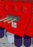
5 1 Install the power switch Align the tab with the hole 2 3x8mm screw 3mm nyloc nut Attach sensor PCB to mounting bracket. 3 Mount sensor PCB on the chassis. 3mm nyloc nuts 3x8mm screws


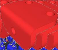
6 4 3x6mm screws 17mm F-F hex spacers 5 2.5x8mm screws Install the motors. Feed motor wires through the hole Feed the sensor through the hole and bend leads at 90 angle. 3. Gently tighten the cable tie so that wires can still be adjusted. 2. Wrap cable tie around the motor to hold sensor and motor cables in place.


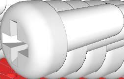
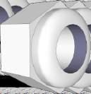
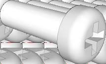
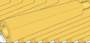
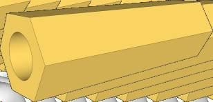
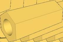
7 7 Align screws with flat sections on the shaft. 5mm fiber washer 8 Push encoder disc onto rear motor shafts. Leave about 3mm (1/8th) space between encoder disc and sensor. 9 3x6mm screws 12mm Hex Spacers


8 10 Optional controller 25mm M-F hex spacers 11 3x6mm screws 12 Fiberglass battery strap 3x6mm screws 6x AA NiMh batteries (not included)


9 13 Connect the wires to the switch. Note position of metal tab.! Warning! Make sure the switch is "OFF" during assembly to prevent accidental short circuit. 14 Pay attention to the wire colours! Battery M3 Wheel 3 You must connect the wires as shown to ensure the robot works correctly with the demonstration software. + - Wheel 2 M1 M2 Wheel 1 15 Encoder 1 Encoder 2 Encoder 3 Pay attention to the wire colours! You must connect the wires as shown to ensure the robot works correctly with the demonstration software. Triangles on PCB indicate signal pin (white wire).

10 16 Use sensor cable to connect the sensor PCB to A7 on the ComMotion controller. Pay attention to the wire colours! You must connect the wires as shown to ensure the robot works correctly with the demonstration software. Connector A7 on ComMotion controller. Testing with the demonstration software The ComMotion shield comes pre-programmed with demonstration software for the Scamper robot. Once the robot is fully assembled check that the encoder disc are a few millimeters away from the sensor and do not touch anything as they spin. Check all the wiring carefully before turning it on. Pay careful attention to the colour of the wires and especially the battery wires. If the power LEDs on the PCB do not light up then quickly turn the robot off and check all power wiring again. When you turn the robot on it should start playing music using the motors for speakers. The robot will then spin as it looks for a line to follow. If the robot had been placed over a line it should start following the line. Pressing the reset button or cycling the power will toggle the demonstation mode on or off. If the robot just beeps a few times then press reset again. If the robot cannot detect the line then try adjusting the small potentiometer on the sensor PCB fully clockwise. Do not use in bright sunlight, this will blind the IR sensor. Black electrical tape is ideal for making lines for the robot to follow.
11 Optional Controller The Scamper robot kit uses the ComMotion PCB as a "stand alone" controller running demonstration software however the ComMotion PCB can also be used as an I²C motor control shield. The advantage of I²C control is that almost all of your IO pins (except A4 and A5) are free for use with other shields, sensors or circuits. Unfortunately most Arduino boards use a large metal USB connector that will short out many shields including the ComMotion shield. We recommend using the SparkFun RedBoard or any other compatible controller that uses a mini or micro USB connector to avoid this problem. Troubleshooting No Power: Turn off the robot and check that the black wire from the battery holder is connected to the negative battery terminal of the controller PCB. Check that the red wire from the battery holder goes to one of the outer pins on the switch. Check that the red wire from the center pin of the switch goes to the positive battery terminal of the controller PCB. Turn on the switch, if the power LEDs do not light up then check all batteries have their positive terminal pressed against the metal connector in the battery holder. Some battery brands can be a tight fit in the battery holder. This prevents the springs from pushing the battery against the opposite contact. Check your batteries are fully charged and inserted the correct way around. Motors constantly speed up and slow down again: This indicates no signal from the encoder. Please check the encoder wiring carefully as shown in step 15. Make sure the sensor is about 3mm (1/8th of an inch) away from the surface of the magnetic encoder disc. Make sure the encoders are plugged into the correct header on the controller. Motors spin in the wrong direction: When the robot powers up it should spin in a clockwise direction, if one or more motors are spinning in the wrong direction then check that the motor is connected to the correct terminal and that the wire colours match those in step 14. Robot does not follow the line: The IR sensor will not work in bright sunlight. If you are indoors then try closing the curtains. Best conditions are a black line about 15-20mm wide on a light coloured floor. Check that the sensor cable is plugged in correctly as shown in step 16. Adjust the small potentiometer on the sensor PCB so that it is fully clockwise. If the robot still does not work then adjust the potentiometer anti-clock wise in small increments and try again.

12 Kit Specifications Chassis: Rollers: Battery: 2mm thick anodized aluminium Natural rubber 6xAA Motor voltage nominal: 6V Motor voltage maximum: 8.4V Motor current no load: Motor current stall: 150mA 6V Gearbox ratio: :1 Encoder disc: 8 pole neodymium magnet Encoder sensor: Open drain hall-effect sensor (3V 22V) Encoder resolution: 625 state changes per wheel revolution ComMotion Specifications Processors: Supply voltage: Logic voltage: Wireless support: Xbee / WiFly power: Battery monitor range: Battery monitor resolution: Analog Inputs: 2x ATmega328P (16MHz) 6V 16V 5V Xbee / WiFly socket with voltage translation 300mA 0V 17V 0.02V 5x 10bit (A3,A6 MCU1 A3,A6,A7 MCU2) Motor drivers: 4x FET H bridge Motor current continuous: 2.5A (each motor) Motor current stall: 4A (each motor) Current monitor range: 0A 5A (each motor) Current monitor resolution: 5mA (each motor) I²C bus voltage: 5V or 3.3V (determined by IO_REF pin) I²C bus speed: 100 kbit/s I²C addresses: 16 selectable pairs (software configurable) Serial ports: 2x 5V TTL logic (FTDI headers)
UGV r o b ot c hassis
 UGV r o b ot c hassis Manual:RS021 Copyright C 2012 by DAGU Hi-tech Electronic Co., Ltd. All rights reserved. No portion of this instruction sheet or any artwork contained herein may be reproduced in any
Assembly Guide for RedBot with Shadow Chassis
 Page 1 of 32 Assembly Guide for RedBot with Shadow Chassis Introduction The SparkFun RedBot is a platform for teaching basic robotics and sensor integration! It is based on the SparkFun RedBoard and fully
SPIDER-MAN 2CH IR HEROCOPTER
 SPIDER-MAN 2CH IR HEROCOPTER I N S T R U C T I O N M A N U A L ITEM NO: 34896 Stabilizer Bar Main Rotor Blades LED Light BOTTOM VIEW PRODUCT INCLUDES: - IR Helicopter - Transmitter - User Manual - Spare
CAPTAIN AMERICA 2CH FLYING FIGURE IR HELICOPTER
 I N S T R U C T I O N M A N U A L ITEM NO: 33190 CAPTAIN AMERICA 2CH FLYING FIGURE IR HELICOPTER Stabilizer Bar Main Rotor Blades LED Light PRODUCT INCLUDES: - IR Helicopter - Remote - User Manual - Main
Educational Robot. Revision 2.0
 Educational Robot www.ridgesoft.com Revision 2.0 IntelliBrain-Bot Assembly Guide 1 Introduction This document provides instructions to guide you through assembly of your IntelliBrain -Bot. It takes approximately
Installation Instructions
 Quick-Mount Visual Instructions for Quick-Mount Visual Instructions 1. Rotate the damper to its failsafe position. If the shaft rotates counterclockwise, mount the CCW side of the actuator out. If it rotates
Installation Instructions
 Quick-Mount Visual Instructions for Mechanical Installation Quick-Mount Visual Instructions 1. Rotate the damper to its failsafe position. If the shaft rotates counterclockwise, mount the CCW side of the
Mobile Robot Design Notes
 Mobile Robot Design Notes The mobile robot is a simple design with two-wheel differential steering and a rear castor. It is designed for teaching use in MTRX3700 Mechatronics 3 and other units of study.
Norcal Power/SWR Meter Assembly & Operating Manual. Revision 1D 10/15/2008
 Norcal Power/SWR Meter Assembly & Operating Manual Revision 1D 10/15/2008 Copyright 2008 NorCal QRP Club Page 1 of 21 Contents CONTENTS...2 INTRODUCTION...3 SPECIFICATIONS...3 ASSEMBLY...4 OPERATING GUIDE...15
Chapter 2. Battery Charger and Base Assembly
 Chapter 2 Battery Charger and Base Assembly 11 CHAPTER 2. BATTERY CHARGER AND BASE ASSEMBLY 2.1 Section Overview This Lab teaches students how to assemble a Tekbot, in the following steps: Describe the
BUMP AND SPIN KIT ESSENTIAL INFORMATION. Version 1.0 PROGRAM AND DESIGN YOUR OWN BUGGY WITH THIS
 ESSENTIAL INFORMATION BUILD INSTRUCTIONS CHECKING YOUR PCB & FAULT-FINDING MECHANICAL DETAILS HOW THE KIT WORKS PROGRAM AND DESIGN YOUR OWN BUGGY WITH THIS BUMP AND SPIN KIT Version 1.0 Build Instructions
ROPE DANCER INSTRUCTION MANUAL:
 Educational Design Robot ROPE DANCER INSTRUCTION MANUAL: Model WTR-RD1 2010 AREXX - THE NETHERLANDS CONTENT 1. Product information Rope Dancer 3 2. General assembly information 4 2.1 Parts list Rope Dancer
WARNING: CHOCKING HAZARD
 Hover Racer WARNING: CHOCKING HAZARD - Small parts. Not for Children under 3 years. To Parents: Please read all instructions before giving guidance to your children. A. SAFETY MESSAGES 1. This kit is intended
Useless Box Kit. Rev 2. March 24, 2014 Kansas State University Electronics Design Club Nathan Reichenberger
 Required Materials: Useless Box Kit Rev 2 March 24, 2014 Kansas State University Electronics Design Club Nathan Reichenberger Quantity Description 1 Double Pole Double Throw Switch 1 Micro Switch 1 Battery
INSTRUCTION MANUAL. Wireless Level Indicator
 INSTRUCTI MANUAL Wireless Level Indicator MODEL S207E www.aquatel.co.nz Aquatel NZ Ltd P.O.Box 225, Orewa 0943 North Auckland, New Zealand External Power Jack 6V DC 4 x AA Alkaline batteries (supplied)
Web Site: Forums: forums.parallax.com Sales: Technical:
 Web Site: www.parallax.com Forums: forums.parallax.com Sales: sales@parallax.com Technical: support@parallax.com Office: (916) 624-8333 Fax: (916) 624-8003 Sales: (888) 512-1024 Tech Support: (888) 997-8267
Installation Instructions 1812 Folder Disk Clutch Retrofit Kit Martin Yale #WRA
 Installation Instructions 1812 Folder Disk Clutch Retrofit Kit Martin Yale #WRA1812510 Background: Early production Martin Yale Model 1812 Folders were originally equipped with a spring-clutch type feed
FlexJet Carriage Circuit Board (PCB) Replacement
 Replacement") P/N: 111484 R0 14140 NE 200th St. Woodinville, WA. 98072 PH: (425) 398-8282 FX: (425) 398-8383 ioline.com FlexJet Carriage Circuit Board (PCB) Replacement Notices: Warning! Ensure that all AC power cables
P/N: 111484 R0 14140 NE 200th St. Woodinville, WA. 98072 PH: (425) 398-8282 FX: (425) 398-8383 ioline.com FlexJet Carriage Circuit Board (PCB) Replacement Notices: Warning! Ensure that all AC power cables
K Wiring and Electronics
 HKBay.com K Wiring and Electronics Written By: HKBay 2017 hkbay.dozuki.com Page 1 of 12 TOOLS: Hex key; ball ended, long arm, 2.5mm (1) PARTS: Arduino Mega (blue) (1) RAMPS board (red) (1) glass tabs (3)
EPAS Desktop Pro Software User Manual
 Software User Manual Issue 1.10 Contents 1 Introduction 4 1.1 What is EPAS Desktop Pro? 4 1.2 About This Manual 4 1.3 Typographical Conventions 5 1.4 Getting Technical Support 5 2 Getting Started 6 2.1
 WWW.MORETRACTION.COM TMS-5500-SL ELECTRONIC TRACTION CONTROL US PATENT 6,577,944 Other Patents Pending COPYRIGHT NOTICE Copyright 1999-2013 Davis Technologies, LLC. All rights reserved. Information in
Issue 2.0 December EPAS Midi User Manual EPAS35
 Issue 2.0 December 2017 EPAS Midi EPAS35 CONTENTS 1 Introduction 4 1.1 What is EPAS Desktop Pro? 4 1.2 About This Manual 4 1.3 Typographical Conventions 5 1.4 Getting Technical Support 5 2 Getting Started
Instruction Manual Installation and Operation Guidelines for DWL5000XY and DWL5500XY Tilt Sensor Modules (Version 2.2)
") Instruction Manual Installation and Operation Guidelines for DWL5000XY and DWL5500XY Tilt Sensor Modules (Version 2.2) INTELLECTUAL PROPERTY This manual contains propriety information, which is protected
Instruction Manual Installation and Operation Guidelines for DWL5000XY and DWL5500XY Tilt Sensor Modules (Version 2.2) INTELLECTUAL PROPERTY This manual contains propriety information, which is protected
To Purchase This Item, Visit BMI Gaming
 Table of Contents General Operation. 3 How Slam-A-Winner plays How the Wheel Scores How the Ball Lift works Programming Options... 4-6 Troubleshooting Guide. 7-8 Parts Identification 9 Schematics 10-13
CENTROIDTM. AC Brushless Drive. Product Spec Sheet
 4 Axis, up to 2 KW motors Brake Output for each axis Overtemp and Overcurrent Protection All-software Configuration Self-cooled Fiber Optic Control CENTROIDTM AC Brushless Drive Product Spec Sheet AC Brushless
Lab 4.4 Arduino Microcontroller, Resistors, and Simple Circuits
 Lab 4.4 Arduino Microcontroller, Resistors, and Simple Circuits A microcontroller is a "brain" of a mechatronic system that interfaces sensors with a computer. Microcontrollers can perform math operations,
TIMED NIGHT LIGHT KIT
 ESSENTIAL INFORMATION BUILD INSTRUCTIONS CHECKING YOUR PCB & FAULT-FINDING MECHANICAL DETAILS HOW THE KIT WORKS RELAX YOUR WAY TO SLEEP WITH THIS TIMED NIGHT LIGHT KIT Version 2.0 Build Instructions Before
VTCM Installation Manual Table of Contents
 VTCM Installation Manual Table of Contents 1. Introduction:... 2 2. Disclaimer:... 2 3. Software / Drivers:... 2 a. Plugging in the controller:... 2 b. Install 4.0.NET Frame work:... 3 c. Install COM port
Motor, Bracket and Wheel Kit (# )
") Web Site: www.parallax.com Forums: forums.parallax.com Sales: sales@parallax.com Technical: support@parallax.com Office: (916) 624-8333 Fax: (916) 624-8003 Sales: (888) 512-1024 Tech Support: (888) 997-8267
Web Site: www.parallax.com Forums: forums.parallax.com Sales: sales@parallax.com Technical: support@parallax.com Office: (916) 624-8333 Fax: (916) 624-8003 Sales: (888) 512-1024 Tech Support: (888) 997-8267
Uno Compatible Pogobed Kit
 Uno Compatible Pogobed Kit Intermediate Level The pogobed kit is a hardware fixture that enables you to temporarily connect from your Arduino development board to any Arduino shield. Using the springloaded
Circuit Basics and Components
 Circuit Basics Electric circuits are arrangements of conductors and components that permit electrical current to flow. A circuit can be as simple as a battery and lamp or as sophisticated as a computer.
CV SINGALONG KEYBOARD STAND & STOOL
 CV SINGALONG KEYBOARD STAND & STOOL POWER SUPPLY Open the battery compartment. Insert 4 x 1,5V batteries LR6/AA (not included). Re-fit battery cover. Use new batteries for best performance. ATTENTION BATTERY
3/6/16 Tetrix first build robot instructions J. La Favre
 Figure 1 mount for Omni wheels - make two of these Figure 2 mount for Omni wheels, add bushing and tighten set screw of axle collar set screw should be tightened down on flat part of axle 1 Figure 3 Insert
BATTERY CHARGER RS-1000 Instruction Manual
 BATTERY CHARGER RS-1000 Instruction Manual BEFORE USING OUR BATTERY CHARGER RS1000, READ IN DETAILS ALL INSTRUCTIONS CONTAINED IN THIS MANUAL. KEEP THIS MANUAL IN A SAFE PLACE AS YOU MAY NEED TO USE IT
Model WS-6020U Solar Station QUICK SETUP GUIDE
 Model WS-6020U Solar Station QUICK SETUP GUIDE Solar-powered Transmitter: Remote transmission of outdoor temperature to the Solar Station by 915 MHz signals LCD displays the outdoor temperature data Recharge
Squarebot Upgrade (2.0 to 3.0) Conversion Instructions (cont.)
 Conversion Instructions (cont.)") Squarebot Upgrade (2.0 to 3.0) Conversion Instructions 1 Collect and identify the parts from the list of materials below: materials qty Squarebot 2.0 1 8-32 hex screw x 1/4 16 8-32 hex screw x 1/2 10 6-32
Squarebot Upgrade (2.0 to 3.0) Conversion Instructions 1 Collect and identify the parts from the list of materials below: materials qty Squarebot 2.0 1 8-32 hex screw x 1/4 16 8-32 hex screw x 1/2 10 6-32
DR-2000 Customer Benefits
 DR-2000 Customer Benefits Security; Tamper resistant programming protects your customer and you! Low maintenance, long battery life & long squeeze tube life; fewer service calls! Compact, Plastic, Water
INSTRUCTIONS ASSEMBLY. CONNECT the RESISTOR. The resistor (re-zis-ter) is the tube-shaped piece with two purple legs. Here we go!
 is the tube-shaped piece with two purple legs. Here we go!") BEFORE YOU BEGIN ASSEMBLING YOUR VOICE CHANGER You will need One 9-volt battery Masking tape or clear tape Adult help (if you re under 10) Now remove the parts from the plastic tray. 1 CONNECT the RESISTOR
BEFORE YOU BEGIN ASSEMBLING YOUR VOICE CHANGER You will need One 9-volt battery Masking tape or clear tape Adult help (if you re under 10) Now remove the parts from the plastic tray. 1 CONNECT the RESISTOR
DIY Bi-Metallic Strip
 DIY Bi-Metallic Strip An introduction to the applications of thermal expansion and two-way switching. Written By: Mahaaveer BN 2018 Page 1 of 14 INTRODUCTION A bi-metallic strip is used to convert a temperature
FlexJet - Flex Cable Replacement
 P/N: 109515R0 14140 NE 200th St. Woodinville, WA. 98072 PH: (425) 398-8282 FX: (425) 398-8383 FlexJet - Flex Cable Replacement Notices: Warning! Ensure that all AC power cables are removed from the printer
Wild Thumper Robot Kit (#28192) Information and Assembly Guide
 Information and Assembly Guide") Web Site: www.parallax.com Forums: forums.parallax.com Sales: sales@parallax.com Technical: support@parallax.com Office: (916) 624-8333 Fax: (916) 624-8003 Sales: (888) 512-1024 Tech Support: (888) 997-8267
Web Site: www.parallax.com Forums: forums.parallax.com Sales: sales@parallax.com Technical: support@parallax.com Office: (916) 624-8333 Fax: (916) 624-8003 Sales: (888) 512-1024 Tech Support: (888) 997-8267
INSTALLATION INSTRUCTIONS
 INSTALLATION INSTRUCTIONS Accessory Application Publications No. SYSTEM 2005 ACCORD All 27511 (DX, LX) 2-AND 4-DOOR Issue Date AUG 2004 PARTS LIST Security System Attachment (LX): P/N 08E55-SDA-100A Unit
ROBOT SOUND REVERSING CAR KIT C-9802
 ROBOT SOUND REVERSING CAR KIT TOOLS you'll need Alimentation 2 batteries 1,5 V AA (not included) You will find fun to learn electronics and mechanics assembling robot by reversing sound. This is a simple
IV-3 VFD Shield for Arduino. Assembly Manual
 June 2014 Table of Contents 1 Overview Features Applications 3 3 3 2 Assembly Hints 4 3 PCB Overview 5 4 Circuit Diagram 6 5 Assembly Diodes and IC socket Electrolytic capacitors Ceramic capacitors 10K
EMG SpikerShield v1.2 Instructions
 EMG SpikerShield v1.2 Instructions Prepare yourself. In 2-4 hours, you will have built your own Arduino compatible EMG SpikerBox, so you can control robots and anything you wish with your EMG muscle activity.
SSV2BR INSTRUCTIONS INSTALLATION INSTRUCTIONS
 SSV2BR INSTRUCTIONS INSTALLATION INSTRUCTIONS CONTROLLER MOUNTING: Find a suitable location to mount the control box. Ideally, as with all pool equipment it should be installed out of direct weather and
DPS32001 and DPS32PS1
 DPS32001 and DPS32PS1 Driver Pack User s Guide A N A H E I M A U T O M A T I O N 4985 E. Landon Drive Anaheim, CA 92807 e-mail: info@anaheimautomation.com (714) 992-6990 fax: (714) 992-0471 website: www.anaheimautomation.com
ReadyPay tm Power System User Manual
 ReadyPay tm Power System User Manual 1 Quick Start Guide Table of Contents Solar Charging Using ReadyPay Power 1 Battery Charge Level Error Reset Place solar panel in the sun The solar panel can be placed
BLHV, BLHV-1. High Voltage Step Motor Driver. User s Guide. (714) fax: (714) website:
 fax: (714) website:") BLHV, BLHV-1 High Voltage Step Motor Driver User s Guide A N A H E I M A U T O M A T I O N 910 East Orangefair Lane, Anaheim, CA 92801 e-mail: info@anaheimautomation.com #L010015 (714) 992-6990 fax: (714)
BLHV, BLHV-1 High Voltage Step Motor Driver User s Guide A N A H E I M A U T O M A T I O N 910 East Orangefair Lane, Anaheim, CA 92801 e-mail: info@anaheimautomation.com #L010015 (714) 992-6990 fax: (714)
Experimental Procedure
 1 of 19 9/10/2018, 11:03 AM https://www.sciencebuddies.org/science-fair-projects/project-ideas/robotics_p023/robotics/line-following-robot (http://www.sciencebuddies.org/science-fair-projects/projectideas/robotics_p023/robotics/line-following-robot)
MCL-3000 SERIES OIL TEMP PART# MCL-3K-TMP
 MCL-3000 SERIES OIL TEMP PART# MCL-3K-TMP Thank you for purchasing the Dakota Digital MCL-3K-TMP gauge for your Harley Davidson Touring bike. This gauge is designed to be a direct, plug in replacement
Installation Instructions
 Quick-Mount Visual Instructions for Mechanical Installation Quick-Mount Visual Instructions. Rotate the damper to its failsafe position. If the shaft rotates counterclockwise, mount the CCW side of the
Combine Cover Manual
 Combine Cover Manual Installation Instructions Page 26 Operating Instructions Page 7 Warranty Page 7 Trouble Shooting Page 8 10 For Big Top Extension Model s: Case I.H. 8010, 8120 Please forward onto Customer
INSTALLATION INSTRUCTIONS
 INSTALLATION INSTRUCTIONS Accessory Application Publications No. AII 31716 HONDA (For ipod ) FIT Issue Date MAR 2006 PARTS LIST Attachment Kit P/N 08A28-1H1-800 4 Cushion tapes Honda Music Link Kit P/N
Step #1 From your spool of 18 gauge primary wire, cut between 11 and 21 three inch strips of wire. You will only need 11 for the ROV, but it is good t
 How to make a ROV! Step #1 From your spool of 18 gauge primary wire, cut between 11 and 21 three inch strips of wire. You will only need 11 for the ROV, but it is good to have extras. Using the wire cutter,
TM4500. Track Mounted Step Motor Driver. User s Guide. CE Certified and RoHS Compliant #L010060
 TM4500 Track Mounted Step Motor Driver User s Guide CE Certified and RoHS Compliant A N A H E I M A U T O M A T I O N 4985 E. Landon Drive Anaheim, CA 92807 e-mail: info@anaheimautomation.com (714) 992-6990
PILOT'S MANUAL 8+ OUTDOOR USE RECOMMENDED. ADULT ASSEMBLY REQUIRED. CAUTION: Surfaces may become hot and cause burns if electronics get wet.
 PILOT'S MANUAL TM 8+ OUTDOOR USE RECOMMENDED. ADULT ASSEMBLY REQUIRED. Keep these instructions for future reference as they contain important information. IMPORTANT: Please read all instructions before
Product Instruction. Door Control Board: Board 1Ø4 for PM/SSC (R3)
") Door Control Board: Board 1Ø4 for PM/SSC 61111-149 (R3) 2000-08-31 2000, 1992 KONE Inc. Unpublished work. All rights reserved. No portion of this volume may be used or reproduced in any manner without
Door Control Board: Board 1Ø4 for PM/SSC 61111-149 (R3) 2000-08-31 2000, 1992 KONE Inc. Unpublished work. All rights reserved. No portion of this volume may be used or reproduced in any manner without
DLF-220L Digital Label Finishing System
 USER MANUAL DLF-220L Digital Label Finishing System this product is certified: IMPORTANT: Please keep the original packaging in case of return. If we receive the system in non-original packaging, the warranty
DJI E2000 Standard Tuned Propulsion System
 DJI E2000 Standard Tuned Propulsion System User Manual V1.0 2016.02 Disclaimer Thank you for purchasing the E2000 Standard Tuned Propulsion System (hereinafter referred to as product ). Read this disclaimer
BLD75-1. Bilevel Step Motor Driver. User s Guide. 910 East Orangefair Lane, Anaheim, CA
 BLD75-1 Bilevel Step Motor Driver User s Guide A N A H E I M A U T O M A T I O N 910 East Orangefair Lane, Anaheim, CA 92801 e-mail: info@anaheimautomation.com (714) 992-6990 fax: (714) 992-0471 website:
Arlo Power Distribution Board Kit Rev B (#28996)
") Web Site: www.parallax.com Forums: forums.parallax.com Sales: sales@parallax.com Technical: support@parallax.com Office: (916) 624-8333 Fax: (916) 624-8003 Sales: (888) 512-1024 Tech Support: (888) 997-8267
Web Site: www.parallax.com Forums: forums.parallax.com Sales: sales@parallax.com Technical: support@parallax.com Office: (916) 624-8333 Fax: (916) 624-8003 Sales: (888) 512-1024 Tech Support: (888) 997-8267
Installation instructions
 Installation instructions Akrapovič Exhaust System: Slip-On for the Porsche 911 Carrera (type 991) Porsche 911 Carrera S (type 991) Porsche 911 Carrera 4 (type 991) Porsche 911 Carrera 4S (type 991) Please
6945 (12v) 6944 (24V) installation instructions
 6944 (24V) installation instructions") 6945 (12v) 6944 (24V) installation instructions included: tools needed: Cordless drill Breezeeasy Fan Mounting brackets 1/4 Drill Bit 10mm Socket Hardware Pack 10mm Wrench Fuse Assembly Wire Stripper Crimper
6945 (12v) 6944 (24V) installation instructions included: tools needed: Cordless drill Breezeeasy Fan Mounting brackets 1/4 Drill Bit 10mm Socket Hardware Pack 10mm Wrench Fuse Assembly Wire Stripper Crimper
CHILDREN S ELECTRONIC TOY ATV
 CHILDREN S ELECTRONIC TOY ATV Suitable for + Years Maximum user weight: 50 kg OWNERS MANUAL with Assembly Instructions Read and understand this entire manual before using! Please keep this manual for future
CCL LLC 88 Black Falcon Ave., Ste. 247, Boston, MA USA Contact: Antea Risso
 88 Black Falcon Ave., Ste. 247, Boston, MA 02210 USA Contact: Antea Risso Digi-Key Corporation e-mail: antea@arduino.org 701 Brooks Ave.South PRODUCT CHANGE NOTIFICATION Thief River Falls, MN 5670 January
Motor, Bracket and Wheel Kit (# )
") Web Site: www.parallax.com Forums: forums.parallax.com Sales: sales@parallax.com Technical: support@parallax.com Office: (916) 624-8333 Fax: (916) 624-8003 Sales: (888) 512-1024 Tech Support: (888) 997-8267
Web Site: www.parallax.com Forums: forums.parallax.com Sales: sales@parallax.com Technical: support@parallax.com Office: (916) 624-8333 Fax: (916) 624-8003 Sales: (888) 512-1024 Tech Support: (888) 997-8267
Table 1: 2-pin Terminal Block J1 Functional description of BSD-02LH Module Pin # Pin Description Table 2: 10-pin Header J2 Pin # Pin Description
 Functional description of BSD-02LH Module The BSD-02LH module is the part of the BSD-02 family of drivers. The main difference is higher microstepping resolution. The BSD-02LH is suitable for driving bipolar
FOR AGES 8 AND UP. 2.4GHz 3.5CH REMOTE CONTROL HELICOPTER ITEM NO
 8+ FOR AGES 8 AND UP 2.4GHz 3.5CH REMOTE CONTROL HELICOPTER ITEM NO. 35922 INTRODUCTION Thank you for purchasing this World Tech Toys product. Please make sure you carefully read the entire manual before
Mini EV Prize Solar Car Kit
 Mini EV Prize Solar Car Kit Each Kit includes 2 x Solar Panels 8 x Wheels 4 x 50mm, 4 x 40mm 2 x Axels (short & long) & 4 x Axel Collars 1 x Motor - F18 & 3D printed mount 2 x Large Spur Gear 60T & 48T
READ AND FOLLOW ALL SAFETY INSTRUCTIONS SAVE THESE INSTRUCTIONS
 7.5 Swift Lock Ready Shape Tree (Patent Pending) Instructions IMPORTANT SAFETY INSTRUCTIONS When using electrical products, basic precautions should always be followed including the following: READ AND
ELECTRIC BICYCLE OWNER S MANUAL
 ELECTRIC BICYCLE OWNER S MANUAL For Owners of EG Kyoto 350 Electric Bicycle Table of Contents Descriptions: Page Installation Instructions 2 How to install the bicycle out of the box 2 Operation Instructions
Contents. Preparing the motor Winding the rotating secondary Winding the primary... 8
 120732-130389 Propeller Clock Construction Notes Revision E, December 2, 2013 Contents Preparing the motor... 2 Winding the rotating secondary... 5 Winding the primary... 8 UltiProp Clock (Elektor Dec.
INSTALLATION INSTRUCTIONS
 INSTALLATION INSTRUCTIONS Accessory USB ADAPTER Application 2014 INSIGHT Publications No. AII 50655 Issue Date OCT 2013 PARTS LIST USB Adapter Attachment Kit P/N 08B28-TM8-100A 6 mm Flange nut Control
LAND ROVER DISCOVERY 3 ARB BULL BAR AND WINCH BAR WARNING
 LAND ROVER DISCOVERY 3 ARB BULL BAR AND WINCH BAR PART No 3432150 DISCOVERY 3 WINCH BAR PART No 3232150 DISCOVERY 3 BULL BAR WARNING FOR VEHICLES EQUIPPED WITH SRS AIRBAG WHEN INSTALLED IN ACCORDANCE WITH
Make Your Own Electricity
 Make Your Own Electricity Topic Electromagnetic induction Introduction Electromagnetic induction the creation of a difference in electric potential between the ends of a conductor moving in a magnetic
AXi-GMBOX1 INSTALLATION MANUAL
 AXi-GMBOX1 INSTALLATION MANUAL PLEASE REVIEW THIS INSTALLATION MANUAL CAREFULLY BEFORE BEGINNING ANY WORK COMPATIBLE PLUG & PLAY WIRING HARNESSES AXI-GM1-C AXI-GMMLX-C AXI-GMQUAD1-C AXI-GMDTS-C AXI-GMSTS-C
BFF Motorised Trim Wheel - Set-up
 BFF Motorised Trim Wheel - Set-up Table of Contents Summary of Set-up Steps...1 BFF Motorised Trim Wheel - Setup Details...2 Final Set-Up For Direct Connection To FSUIPC/XPUIPC...5 Final Set-Up For Direct
DJI E1200 Standard. Tuned Propulsion System. User Manual V
 DJI E1200 Standard Tuned Propulsion System User Manual V1.2 2015.8 Disclaimer Thank you for purchasing the E1200 Standard Tuned Propulsion System (hereinafter referred to as product ). Read this disclaimer
Daymak Drive Application ios. User Guide
 Daymak Drive Application ios User Guide Thank You Thank you for your purchase of our Daymak product. By choosing to utilize an electric vehicle, you are actively doing your part to reduce your carbon footprint.
D1.4.6_
 Makeblock Co., Ltd. Address: 4th Floor, Building C3, Nanshan ipark, No.1001 Xueyuan Avenue, Nanshan District, Shenzhen, Guangdong Province, China Technical support: support@makeblock.com www.makeblock.com
Conflicts: Vehicles with a sunroof
 Toyota 4Runner Non/MR 2010-10.2 Overhead Video Part Number: 00016-00110; Fit Kit -00110-15, Beige 00016-00120; Fit Kit -00120-15, Gray Accessory Code: ED6 Conflicts: Vehicles with a sunroof Kit Contents:
Overhead Twin Line Irrigation Installation Guide COM 2 Copyright First Tunnels Ltd 2012.
 www.firsttunnels.co.uk/quality Overhead Twin Line Irrigation Installation Guide COM 2 Copyright First Tunnels Ltd 2012. Warnings General Please keep children and pets away from the work area. If any holes
DJI E800 Multirotor Propulsion System
 DJI E800 Multirotor Propulsion System User Manual V1.0 2015.01 Disclaimer Thank you for purchasing the E800 (hereinafter referred to as product ). Read this disclaimer carefully before using this product.
Azatrax MRX3 Grade Crossing Signal Controller Installation Guide
 Azatrax MRX3 Grade Crossing Signal Controller Installation Guide What it is: The MRX3 is a sophisticated controller that realistically operates model railroad / highway crossing signals. The MRX3 includes
Week 11. Module 5: EE100 Course Project Making your first robot
 Week 11 Module 5: EE100 Course Project Making your first robot Dr. Ing. Ahmad Kamal Nasir Office Hours: Room 9-245A Tuesday (1000-1100) Wednesday (1500-1600) Course Project: Wall-Follower Robot Week 1
Quick Starter Manual for PrusaM201
 Quick Starter Manual for PrusaM201 Copyright Declaration The copyright of this specification belongs to the Shenzhen GETECH CO., LTD. (hereinafter referred to as the "Geeetech"), and all rights reserved.
SPREADER SYSTEM. Proportional three function. 1. Features and Specifications. User Manual 12 INPUTS 12 OUTPUTS CONNECTIVITY MAIN FEATURES
 User Manual SPREADER SYSTEM Proportional three function 12 INPUTS 3 interrupt digital inputs. 3 digital inputs for engine control (alternator, accelerator, oil alarm). 1 digital input for tachometer (squared,
INSTALLATION INSTRUCTIONS
 INSTALLATION INSTRUCTIONS Accessory Application Publications No. BII 39552 ENGINE BLOCK 2009 RDX Issue Date P/N 08T44-SJA-200 MAY 2008 PARTS LIST NOTE: NOTE: Installation of the engine block heater requires
WS-9116U Wireless 433 MHz Temperature Station. Instruction Manual
 WS-9116U Wireless 433 MHz Temperature Station Instruction Manual 1 TABLE OF CONTENTS Topic Page Inventory of Contents 3 Quick Setup 4-6 Detailed Setup Guide Battery Installation 7-8 Features Minimum and
BATTERY CHARGER Instruction Manual
 BATTERY CHARGER Instruction Manual BEFORE USING OUR BATTERY CHARGER, READ IN DETAILS ALL INSTRUCTIONS CONTAINED IN THIS MANUAL. KEEP THIS MANUAL IN A SAFE PLACE AS YOU MAY NEED TO USE IT LATER. We draw
USER'S MANUAL MODEL DPS32PG1 DRIVER PACK
 USER'S MANUAL MODEL DPS32PG1 DRIVER PACK ANAHEIM AUTOMATION 4985 E. Landon Drive Anaheim, CA 92807 Phone: (714) 992-6990 Fax: (714) 992-0471 http://www.anaheimautomation.com Email: info@anaheimautomation.com
Owner s Manual Folding Trike
 Owner s Manual Folding Trike THIS MANUAL CONTAINS IMPORTANT SAFETY, ASSEMBLY, OPERATION AND MAINTENANCE INFORMATION. PLEASE READ AND FULLY UNDERSTAND THIS MANUAL BEFORE OPERATION. SAVE THIS MANUAL FOR
The CMPE 118 Cockroach Robot Dept. of Computer Engineering, UCSC
 The CMPE 118 Cockroach Robot Dept. of Computer Engineering, UCSC Background: The CMPE-118 Cockroach robot is designed to be an accessible mobile platform to teach you basic state machine programming. This
NANO HERCULES ITEM NO INSTRUCTION MANUAL 3.5 CHANNEL IR HELICOPTER AGES 8+
 NANO HERCULES 3.5 CHANNEL IR HELICOPTER INSTRUCTION MANUAL AGES 8+ ITEM NO. 35939 REMOTE CONTROL TRANSMITTER LIGHT BUTTON INFRARED EMITTER TURBO BUTTON CHANNEL SELECTOR THROTTLE FORWARD/BACKWARD/ LEFT
Stevens Type A/F Encoder. For Stand-Alone Encoder Part # AND Encoder Attachment Part # INSTRUCTION 90044
 Stevens Type A/F Encoder For Stand-Alone Encoder Part # 90043 AND Encoder Attachment Part # 44903 INSTRUCTION 90044 Table of Contents SAFETY AND EQUIPMENT PROTECTION 3 1 INTRODUCTION... 5 1.1 GENERAL DESCRIPTION...
Toyota 4RUNNER With/MR Overhead Video
 Toyota 4RUNNER With/MR 2010-10.2 Overhead Video Part Number: 00016-00110; Fit Kit-00110-14, Beige 00016-00120; Fit Kit-00120-14, Gray Accessory Code: ED7 Conflicts: Vehicles without a sunroof Kit Contents:
OWNERS MANUAL. Gold Series
 LUNAR OWNERS MANUAL Comfort Base Gold Series Contents Safety Information...3 What Is Included...6 Assembly - Base...7 Location of Controls - Remote...11 Operation - Main...11 Operation - Linking the Remote...12
Prusa i3 Printer Assembly Guide
 Prusa i3 Printer Assembly Guide Special thanks to Carlos Sanchez and Miguel Sanchez for the graphics. All graphics captured from their great animation: http://www.carlos-sanchez.com/ Prusa3/ For copyright
Electronic Dynamo Regulator INSTRUCTION MANUAL. COPYRIGHT 2014 CLOVER SYSTEMS All Rights Reserved
 DRM TM DRM-HP TM Electronic Dynamo Regulator INSTRUCTION MANUAL COPYRIGHT 2014 CLOVER SYSTEMS All Rights Reserved INTRODUCTION The Clover Systems DRM is a state-of-the art all-electronic voltage and current