Wye or Delta Systems DS9181 (CSA Approved)
|
|
|
- Rudolf Shepherd
- 6 years ago
- Views:
Transcription
1
2 6-2 High-resistance Grounding Equipment Wye or Delta Systems DS9181 (CSA Approved) 240, 480, 600 Volts WHERE TO USE The function of a high-resistance grounding equipment is: 1. To provide a ground for neutral of an ungrounded three-phase power system, utilizing the high-resistance method. Using this equipment allows the system to operate basically as an ungrounded system. The equipment is designed to eliminate the danger of high transient overvoltages during certain types of ground faults. NOTE: The use of high-resistance grounding on 600-volt maximum systems precludes line-to-neutral loading. 2. To provide an immediate warning when the first ground fault occurs through an alarm system. 3. To provide a method for quickly locating and removing the fault before another fault develops on another phase, thereby preventing circuit outages due to double line-to-ground faults. This is done by using the pulsing ground current feature and portable detector. Equipment Range Taps are provided on the standard DS9181 grounding resistor to adjust for a system charging current maximum of 3.5 amps or less. Since the normal charging current for most 600-volt or less systems is usually below one ampere, our standard equipment is adequate; however, for systems with greater charging currents refer to the Company. Data for estimating the system charging current is shown in GEI DESCRIPTION OF OPERATION OF STANDARD EQUIPMENT LOW VOLTAGE The circuits used for low-voltage systems are shown in Fig. 1 and Fig. 2. During normal conditions, with no ground fault on the system, only a small magnetizing current (capacitance-charging current) flows in the grounding transformers and no voltage appears across the resistor. When a ground fault occurs, the resistor limits the ground current to a low value. Taps are provided on the resistor to adjust the magnitude of the ground current in the range of 0.9 to 3.6 amperes, depending on the size of the system, so that the current supplied by the resistor to a ground fault will be slightly greater than the system s natural capacitance-charging current. The voltage appearing across the resistor will be sensed by the meter relay. Auxiliary contacts in the control, operated by the meter relay, are available for remote indication and annunciation of a ground. A green indicating light on the equipment indicates the control voltage is available and that the system is normal. When a fault develops, a red indicating light on the equipment will light and remain lighted until the ground fault is removed. To trace the ground fault, the operator turns the selector switch to the pulse position. This initiates cycle timing, alternately energizing and de-energizing a shorting contactor at the secondary resistor, resulting in a rhythmic fluctuation in the magnitude of the ground current. The portable hook-on detector is then used to trace the fluctuations in ground current through the system to the point of fault. After the ground point has been located and removed from the system, the operator then resets the selector switch to de-energize the pulse-cycle timing circuits. The grounding transformer for delta systems will consist of three single-phase transformers connected wye-delta. For wye systems, where system neutral is available, these grounding transformers are not needed. Fig volts maximum wye systems Fig volts maximum delta systems
3 High-resistance Grounding Equipment 6-3 Wye or Delta Systems DS , 480, 600 Volts Fig. 3. DS9181WB Type 1 wall-mounted panel for 600-volt (max) wye or delta systems Fig. 4. DS9181 Type 1CV floor-mounted panel for 600-volt (max) wye or delta systems SPECIFICATIONS Equipment Included in Standard 240-, 480-, or 600- volt Wye and Delta Systems 1 Line Isolator, three phase, interlocked with the door 3 Line fuses, 600 volts, 10 amp, interrupt 200,000 amps RMS symmetrical 3 Neutral deriving transformers, dry-type (delta system only) 1 Control power transformer (CPT) 1 Meter relay (double set point) 1 Pulsing contactor, set to produce approximately 40 current pulsations per minute 1 Neutral-grounding resistor (separately mounted), cont. rated 1 Relay for pulsing contactor 1 Control relay, with interlocks for remote alarm 1 Ground Fault red indicating light 1 Normal green indicating light 1 Normal-Pulse selector switch 1 TEST resistor 1 TEST pushbutton (momentary type) 1 Instruction plate on door 1 Wall-mounted enclosure (floor mounted is optional) 1 Portable ground-current detector with carrying case. (Optional must be ordered as a separate item.) X Control circuit operates from 120 volts supplied by secondary of CPT. X All connections to control and annunciator circuits wired to terminal boards X Cable entry from top or bottom X Optional Modifications (See page 6-7.) Resistor is mounted inside DS9181L floor-mounted panel. DIMENSIONS All dimensions in inches. Type 1 (outline 273A3617 Sh. 1) Approximate Weight Wye pounds Delta pounds Type 3 (outline 273A3617 Sh. 2) Approximate Weight Wye pounds Delta pounds Fig. 5. Dimensions and weights of DS9181W (240-, 480- or 600 volt, wye or delta systems) in wall-mounted enclosure
4 6-4 High-resistance Grounding Equipment Wye or Delta Systems DS , 4160 Volts Equipment Range Taps are provided on the standard DS9181 grounding resistor to adjust for a system charging current maximum of 5.8 amps or less (maximum 3.3 amps or less for 4160 volts delta). Since the normal charging current for most 4160-volt or less systems is usually below this, our standard equipment is adequate; however, for systems with greater charging currents refer to Company. Data for estimating the system charging current is shown in GEI DESCRIPTION OF OPERATION OF STANDARD EQUIPMENT HIGH VOLTAGE SPECIFICATIONS The system operation is the same as was described for the 600-volt (max) systems. One line diagrams for or 4160-volt systems are as shown in Fig. 9 and 10. Taps are provided on the secondary resistor to adjust the magnitude of the ground current, in the range of 2 to 6 amperes (1.2 to 3.5 amperes on 4160-volt delta). The resistor tap value should be set slightly higher than the system s natural capacitance-charging current. For example, if the system capacitance-charging current is measured at 1.9 amperes, the resistor taps should be set for approximately 2 amperes ground current, with a periodic increase during pulsing to 4 amperes. Equipment included in standard or 4160-volt wye and delta systems: 1 Draw-out line isolator with 1 line fuse (3 fuses for delta system) 1 Grounding transformer, dry-type (3 for delta system) 1 Meter relay 1 Door switch (DSW) 1 Pulsing contactor, set to produce approximately 40 current pulsations per minute 1 Neutral-grounding resistor (mounted on top of panel or separately mounted), cont. rated 1 Relay for pulsing contactor 1 Control relay, with interlocks for remote alarm 1 Control-power disconnect switch 2 Control fuses 1 Ground Fault red indicating light 1 Normal green indicating light 1 Normal-Pulse selector switch 1 TEST pushbutton (momentary type) 1 Instruction plate on door 1 Floor-mounted enclosure (wall mounted not available) 1 Portable ground-current detctor with carrying case. (Optional must be ordered as a separate item.) X Control circuit operates from remote source supplied by purchaser X All connections to control and annunciator circuits wired to terminal boards X Cable entry from top or bottom X Optional modifications (See Table 6, page 6-8 for description.) Fig. 6. DS9181, 4160-volt delta system in Type 1 floormounted enclosure with resistors mounted on top Fig. 7. DS9181, 4160-volt delta system, panel doors open, with resistors mounted on top Fig. 8. DS9181, 4160-volt delta system, in Type 3 floormounted enclosure
5 High-resistance Grounding Equipment 6-5 Wye or Delta Systems DS , 4160 Volts DESCRIPTION OF OPERATION (Cont d) DIMENSIONS Fig or 4160-volt wye systems Voltage Encl Type D (In Inches) Net Weight (lbs) Wye Delta Wye Delta 2400, , A Resistors may be mounted separate. See Table 3, page 6-7. B Incoming terminal connection C Recommended position for incoming power conduit Fig. 11. Dimensions of DS9181HA or HC (2400- or 4160-volt wye or delta systems) Fig or 4160-volt delta systems
6 6-6 High-resistance Grounding Equipment Wye or Delta Systems DS9181 Ground-current Detector* (Cat # 245A2006P1) The ground-current detector is a modified portable hook-on type ammeter and includes the following special features: Multi-range switch. Large window, suitable for conduits up to 5 inches nominal diameter. Removable arm to facilitate use in limited spaces where conduits are closely adjacent. Shorting switch to provide transient protection while detector is being positioned around conductors. Closed magnetic core to minimize effects of stray fields. For use on systems rated up to 4160 volts nominal, the handle is insulated making it suitable for use where cables are not in conduit. * Minimum quantity one (1) required at the installation site. Fig. 12. Portable detector with carrying case HOW TO ORDER DS9181 SYSTEMS (See TABLES 1-6) Order by complete DS9181 catalog number. EXAMPLE: Quantity 1 Type 1 wall-mounted panel with pulser for 480-volt wye, 60-Hertz system. Order 1 DS9181WAY108B1XX1 (from TABLE 1) (includes grounding resistor in NEMA 1 enclosure for separate mounting) and order 1 DS9181 Cat. No. 245A2006P1 ground-current detector with carrying case each from TABLE 4). 240, 480, 600, 2400, 4160 Volts TABLE , 480-, and 600-volt systems Standard wall-mounted panels Description Catalog Number DS9181W TYPE }PANEL Standard, with pulser A } Standard, without pulser B-Use A form NEC/Calif Code, with pulser C NEC/Calif Code, without pulser D-Use C form SYSTEM TYPE Delta, 60 Hertz DO Wye, 60 Hertz Y1 Delta, 50 Hertz OBS Wye, 50 Hertz OBS SYSTEM VOLTAGE AND RELAY MODIFICATIONS 240-volt, Standard volt UV 02-Use 04 form 240-volt TR 03-Use 04 form 240-volt UV TR volt, Standard volt UV 09-Use 11 form 480-volt TR 10-Use 11 form 480-volt UV TR volt, Standard volt UV 16-Use 18 form 600-volt TR 17-Use 18 form 600-volt UV TR 18 RESISTOR MOUNTING For separate mounting and wiring by Customer. (Cannot be mounted inside or on top of Panel) B TYPE OF ENCLOSURE FOR RESISTOR Open (no enclosure) X Indoor Cover 1 Outdoor Weatherproof 3 MODIFICATIONS None (standard) XX AM & separate mounted CT (Delta form only) AM Holding relay, reset push button, AM, CT (Wye form only) HM EQUIPMENT ENCLOSURES Type 1 1 Type 3 3 Type 12 C See TABLE 6 for description of Modifications. For dimensions of wall-mounted panels see Fig. 5, page 6-3. Approximate dimensions of resistor: W D H Open (Fig. 23, Part 24, page 3-2) Indoor Cover (Fig. 23, Part 24, Note 1, page 3-10) Outdoor Weatherproof (Fig. 24, Part 25, Page 3-11)
7 } } } } High-resistance Grounding Equipment 6-7 Wye or Delta Systems DS9181 HOW TO ORDER (Cont d) TABLE , 480-, and 600-volt systems Optional floor-mounted panels Description Catalog Number DS9181L PANEL TYPE Standard, with pulser A Standard, without pulser B-OBSOLETE Use A form NEC/Calif Code, with pulser* C NEC/Calif Code, without pulser* D-OBSOLETE Use C form SYSTEM TYPE Delta, 60 Hertz D0 Wye, 60 Hertz Y1 Delta, 50 Hertz D2-OBSOLETE Wye, 50 Hertz Y3-OBSOLETE SYSTEM VOLTAGE AND RELAY MODIFICATIONS* 240-volt, Standard volt UV 02-Use 04 form 240-volt TR 03-Use 04 form 240-volt UV TR volt, Standard volt UV 09-Use 11 form 480-volt TR 10-Use 11 form 480-volt UV TR volt, Standard volt UV 16-Use 18 form 600-volt TR 17-Use 18 form 600-volt UV TR 18 RESISTOR MOUNTING Mounted and wired inside equipment enclosure AX MODIFICATIONS* None (standard) XX CT and AM AM Holding Relay, Reset push button, Ammeter, CT (Wye form only) HM EQUIPMENT ENCLOSURES Type 1 CV 1 Type 3 CV 3 Type 12 CV C Approximate Dimensions and Weights Equipment Enclosure W D H With Pulser Without Pulser In Pounds In Pounds (In Inches) Wye Delta Wye Delta Type 1CV Type 3CV Type 12CV FOOTNOTES FOR TABLES 2&3 * See TABLE 6 for description of modifications. CV is convection cooled. Wall-mounted enclosure not available for and 4160-volt applications. Refer to Company for dimensions. Resistor is for separate mounting and wiring by Customer. Refer to Fig. 11, page 6-5, for dimensions and weights. 240, 480, 600, 2400, 4160 Volts TABLE and 4160-volt systems Standard floor-mounted panels with pulser Description Catalog Number DS9181H PANEL TYPE Standard, with pulser A NEC/Calif Code, with pulser C SYSTEM TYPE Delta, 60 Hertz D0 Wye, 60 Hertz Y1 Delta, 50 Hertz D2-OBSOLETE Wye, 50 Hertz Y3-OBSOLETE SYSTEM VOLTAGE AND RELAY MODIFICATIONS* 2400-volt, Standard volt UV 02-Use 04 form 2400-volt TR 03-Use 04 form 2400-volt UV TR volt, Standard volt UV 09-Use 11 form 4160-volt TR 10-Use 11 form 4160-volt UV TR volt, Standard 15-OBSOLETE 3300-volt UV 16-OBSOLETE 3300-volt TR 17-OBSOLETE 3300-volt UV TR 18-OBSOLETE RESISTOR MOUNTING Panel mounted (on top in own enclosure) A Shipped separate in own enclosure B TYPE OF ENCLOSURE FOR RESISTOR Open (no enclosure all systems) 0 Type 1 (4160 volts wye) 1 Type 3 (4160 volts wye) 2 Type 1 (4160 volts delta, 2400 volts wye or delta) 3 Type 3 (4160 volts delta, 2400 volts wye or delta) 4 MODIFICATIONS* Holding Relay, Reset push button, Ammeter, CT HM None (standard) XX CT and AM AM EQUIPMENT ENCLOSURES Type 1 1 Type 3 3 Type 12 C TABLE 4 Ground-current detector (modified portable hook-on type ammeter) and carrying case Maximum System Cat. No. Voltage 245A2006P TABLE 5 (Description of modifications applicable to all panels) Mod. Item Function UV Undervoltage Relay Drops out on low voltage and provides auxiliary contacts for meter relay failure remote alarm. TR Timing Relay Prevents nuisance tripping on temporary transient faults. NEC/Calif. Code Door Switches Allows panel to meet California Code and NEC. CT Current Transformer Detects ground current AM Ammeter Indicates ground current
8 6-8 Neutral Grounding Resistors Type DS300C Stainless-steel Neutral Grounding Resistors WHERE TO USE Use for resistance grounding of industrial power systems. Connect between ground and neutral of wye-wound transformers or generators. Neutral grounding resistors are rated in line-to-neutral voltage, initial current amperes and allowable-time-on. The line-toneutral voltage corresponds to the system s voltage divided by The initial current is the current which would flow if rated voltage were present and resistance not affected by temperature rise. Listed neutral grounding resistors are designed, tested, and rated in accordance with IEEE Standards No Typical grounding resistor schematic SERVICE REQUIREMENTS The two classes of service requirements for neutral grounding resistors, as established by IEEE Standard , are steady state and rated time. RATED TIME Ten-second Rating This is the shortest time rating applied to neutral grounding devices which are used to reduce the ground current that may flow through a piece of equipment. The current permitted is usually considerably greater than the fullload current, so that dependence must be placed upon the relay operation to prevent damage not only to the neutral device but also to the main equipment. One-minute Rating A common use of neutral grounding devices has been to limit ground currents on outgoing feeders during faults to ground in order to reduce damage at the fault, limit overvoltages between sound phases and ground, and improve voltage regulation. Extended-time Rating For all applications where a ground fault is permitted to persist for longer than ten minutes, the grounding device should have a rating based upon the temperature reaching a constant maximum value, but selected on the basis that such operation will be infrequent. The temperature rise permitted may be higher than the standard temperature rise for steady-state service, assuming that operations at maximum temperature will not be required for more than an average of 90 days per year with an average ambient not exceeding 30 C. STEADY STATE The IEEE standards have established for the continuous-current-rated neutral grounding resistors an allowable temperature rise of 385 C under steady-state conditions. For the extended-time rating, a temperature rise of 610 C is permitted for stainless-steel resistors. Thus, if the lower temperature rise is desired for stainlesssteel-type resistors or if the resistor is to be on for an average above 90 days per year, a steady-state rating should be specified. Mine Service Requirements Where neutral grounding resistors have been specified for mining service applications, the Department of the Interior, Bureau of Mines-Mandatory Safety Standards for Coal Mines, sections and , specifies that the ground fault current rating of grounding resistors shall meet the extended time rating set forth in AIEE #32 (IEEE # ). Therefore, an extended time rating should be specified for such applications. Seismic Shock Requirements Where the application requires the neutral grounding resistor to be rated for seismic shock, specific requirements in terms of magnitude and frequency of the vibration should be obtained. Hazardous Location Requirements In areas where fire or explosion hazards may exist, the temperature rises allowed by IEEE are likely to exceed the ignition temperature of the gas or vapor involved. It will be necessary to refer requests for neutral grounding resistors for hazardous locations to the company for a quotation, specifying the ignition temperature in degrees celsius of the gas or vapor involved. Resistors will be designed for a maximum operating temperature of the resistive element not to exceed 80 percent of the ignition temperature. Altitudes above 3300 Ft (1000 M) Resistors listed in this section are designed and rated for use at altitudes not exceeding 3300 ft (1000 M). For applications at higher altitudes, it will be necessary to refer to the company for a quotation. Resistance Tolerance The listed 85A and DS300C resistors are manufactured to a resistance tolerance of plus or minus 10 percent of the nominal furnished value. Rated Current The rated current for a neutral grounding resistor is the initial value of current, assuming a constant voltage is applied to the resistor. Resistors with ten-second, 60-second or extended-time rating have zero (0) continuous-duty-current rating. Tests Standard factory tests performed on the 85A and DS300C resistor consist of resistance measurement and applied potential tests only in accordance with routine tests as defined by IEEE , Sections and (second paragraph), respectively. EQUIPMENT DESCRIPTION DS300C Stainless-steel Resistors (Open frame) DS300C neutral grounding resistors consist of ceramic-core ribbon-wound units arranged in tiers within an open frame. (Fig. 1). Each unit is insulated from the tier structure. For systems above 600 volts, the frame assembly is supported on ANSI-70 gray insulators rated 7.5 kv or higher to provide insulation from ground. The standard frame is constructed of hot dipped galvanized steel with zinc plated hardware. (Optional frame constructions available are aluminum or stainless steel, each with stainlesssteel hardware. Refer to company for quotation.) Fig. 17. DS300C stainless-steel resistor in open frame with support insulators DS300C Stainless-steel Resistors (Open Frame) (Cont d) Line and ground connections on DS300C resistor are external to frame and consist of through-stud-type entrance bushings with 5/8-inch - 11 stud. For systems with line-to-neutral, voltages greater than 4160 volts, resistor will consist of two or more frames. Frames may be stacked (2-high frames maximum) for most 10- and 60-second ratings. DS300C open resistors can be installed indoors or outdoors. No weather-protective enclosure is required. Support insulators are shipped separately to prevent breakage in transit. See page 4-13 for principal characteristics.
9 Neutral Grounding Resistors 6-9 Type DS300C Stainless-steel Neutral Grounding Resistors (Cont d) EQUIPMENT DESCRIPTION (Cont d) DS300C Resistor with Bolt-on Ventilated Covers Bolt-on ventilated covers (attached to all six sides of the resistor frame) are intended to protect the resistor from falling objects, and prevent entry of birds and rodents. Cover plates are furnished for the lifting holes in the resistor frame. The ventilated covers are constructed of hot dipped galvanized steel with 0.25-inch 1.50-inch rectangular openings spaced 0.2-inch apart, providing approximately 49-percent opening for ventilation. Refer to Fig. 18. Fig. 18. DS300C neutral-grounding resistor with ventilated covers attached to frame DS300C Resistor with Grounded Safety-screen Enclosures For indoor or outdoor pad-mounted applications on systems rated greater than 600 volts line-to-line, the DS300C open frame resistor with grounded safety-screen enclosure should be used to provide for personnel safety (Refer to Fig. 19). Fig. 19. DS300C resistor in grounded safety-screen enclosure The open frame resistor is then surrounded at top and 4 sides by a self-supporting screen enclosure that provides adequate electrical clearance from the resistor frame based on system voltage. The safety enclosure is bolted to the floor (on concrete pad) by purchaser. There is no bottom screen. Sides are removable for customer access. The screens are constructed of galvanized expanded metal with 1.2-inch by 2.6-inch diamond-shaped openings. Entrance of the purchaser s incoming neutral connection is normally made through the top screen utilizing an optional stud-type entrance bushing. (Refer to TABLE 1, page 4-20.) Stands DS300C Resistor Stand Resistor mounting stands are structures which elevate the resistor frame (frames) above ground level and can be used to provide personnel safety (refer to Fig. 20). The stand provides support for the resistor and is available with either 4-foot or optional 8-foot legs. The standard offering is a stand assembly made with steel angle legs and support members which are hot dipped galvanized steel for outdoor service. The top of the stand is covered with galvanized welded-wire screening. The stand includes a grounded safetyscreen enclosure. Standard enclosure is galvanized expanded-metal construction (as previously described). All stands with the grounded safety enclosure include mounting provisions on the top screen for one entrance bushing, one stand-off insulator and one JKW current transformer, each rated up to 15 kv. The current transformer may be mounted outside on the top screen or suspended from the top screen inside the enclosure (Refer to Fig. 31 and 32). Stands with 4-foot legs always include the grounded safety enclosure to provide personnel protection, because the closest electrical live point would be a maximum of 4 feet 9 inches above ground level. All stands and safety enclosures are bolted construction. All stands are shipped partially assembled. Safety enclosures used with the stands may be shipped completely unassembled or assembled (depending on size). DS300C Entrance Bushing Entrance bushings are available for mounting on top screen of pad-mounted or stand-mounted safety enclosures to allow Fig. 20. Stand with 4-foot legs and grounded galvanized safety-screen enclosure for means of connecting customer s incoming neutral conductor to the resistor. These ANSI-70 light gray bushings are assembled through stud type rated 400 amperes continuous, which is adequate for use with all catalog-listed DS300C resistors. Optional universal clamp-type terminal assembly for entrance bushing is available for use with copper or aluminum cable from Size #2 to 600 MCM. DS300C Current Transformers (CT) JKW wound-type current transformers are available for applications up to 15 kv maximum with a maximum ratio of 800:5 for JKW-3 (5 kv) and JKW-4 (8.7 kv) and 1200:5 for JKW-5 (15 kv). These current transformers may be used indoors or outdoors without a weather-protective enclosure. The bottom insulators for resistor frame are commonly referred to as stand-off insulators or support insulators and are included in the price of the resistor. DS300C Resistor Terminations Type DS300C resistors are supplied with line and ground connection points external to the frame consisting of through stud type entrance bushings with 5/8-inch - 11 copper studs. DS300C Cabling Where the resistor rating requires two frames or more and the frames are stacked, the connection between frames is included. Where the rating requires two or more frames that are not stackable (such as extended time ratings), the connection between frames must be supplied by purchaser. Cabling to and from entrance bushing and current transformer must also be supplied by the purchaser.
10 6-10 Neutral Grounding Resistors Type DS300C Stainless-steel Neutral Grounding Resistors (Cont d) Specifications DS300C Stainless-steel Resistors Characteristic or Property DS300C Stainless-steel Type RESISTANCE MATERIAL a. Short time rating 10 minutes or below a. AISI-430 chrome stainless steel or AISI-406 iron, chromium, stainless steel as determined by rating b. Extended time ratings b. AISI-406 iron, chromium, aluminum, stainless steel TEMPERATURE RISE (in accordance with IEEE-32 Standards). 30 C ambient a. Short time ratings a. 760 C rise b. Extended time ratings* b. 610 C rise c. Continuous ratings c. 385 C rise TEMPERATURE COEFFICIENT OF a. AISI RESISTANCE b. AISI CHANGE IN RESISTANCE WITH TEM- PERATURE (over the Operating Temperature Range) a. Short time ratings a. 90% increase b. Extended time ratings Per IEEE-32 b. 13% increase CORROSION RESISTANCE RESISTANCE TOLERANCE The stainless-steel type resistors are inherently corrosion resistant and virtually immune to progressive pitting and rusting. The ceramic insulators are not appreciably affected by exposure to condensation, dust and other foreign materials. These resistors may be used outdoors completely exposed to the weather without an enclosure. 10 percent
11 Neutral Grounding Resistors 6-11 Type DS300C Stainless-steel Neutral Grounding Resistors 10-second Rating for Indoor or Outdoor Service Initial Current in Amperes Total Resistance Ohms Calculated Nominal Furnished Resistor Catalog Number DS300C Number of Frames Fig. No. Dimensions Part No. Enclosure or Stand Group Number 139 VOLTS LINE-TO-NEUTRAL (240-VOLT SYSTEM) 10-SECOND RATING A A A A VOLTS LINE-TO-NEUTRAL (480-VOLT SYSTEM) 10-SECOND RATING A A A A A A VOLTS LINE-TO-NEUTRAL (2400-VOLT SYSTEM) 10-SECOND RATING A B A B A B A B A B A B VOLTS LINE-TO-NEUTRAL (4160-VOLT SYSTEM) 10-SECOND RATING A25 435C A50 423C A C A C A C A C A C A C A C A C A C A C A C VOLTS LINE-TO-NEUTRAL (7200-VOLT SYSTEM) 10-SECOND RATING A25 449C A50 433C A C A C A C A C A C A C VOLTS LINE-TO-NEUTRAL (12,470-VOLT SYSTEM) 10-SECOND RATING A G A G A G A G A G A G A G A G VOLTS LINE-TO-NEUTRAL (13,900-VOLT SYSTEM) 10-SECOND RATING A G A G A G A G A G A G A G A G A G A G A G * If resistor open frame, insert A in this space. If resistor with bolt-on covers, insert B in this space.
12 6-12 Neutral Grounding Resistors Type DS300C Stainless-steel Neutral Grounding Resistors MODIFICATIONS DS310 Enclosures and/or Stands and Accessories Using TABLE 1 below, select complete DS310 catalog number for enclosure and/or stand assembly and accessories required for the application. (When an enclosure and/or stand assembly is selected from TABLE 1, a complete DS310 catalog number is required. Refer to pricing example on page 4-13.) TABLE 1 Enclosures, Stands and Accessories Catalog Number DS310 TYPE OF ENCLOSURE OR STAND Galvanized safety-screen enclosure A Aluminum louvered safety enclosure B Galvanized-steel stand with 4 ft legs and galvanized safety screen enclosure For resistor - one frame or two frames stacked... E For resistor - two frames side by side M Galvanized-steel stand with 8 ft. legs, and galvanized safety screen enclosure.... For resistor - one frame or 2 frames stacked... K Galvanized-steel stand with 8 ft. legs, no enclosure... For resistor - one frame or 2 frames stacked... H No enclosure, no stand... N CURRENT TRANSFORMER FUNCTION Without CT mounting provisions... 0 With CT mounting provisions ENCLOSURE OR STAND GROUP NUMBER Insert group number from last column of resistor pricing tables, pages 4-14 to 4-18 here (Note: Price adder per group no. depends on type of enclosure or stand.) GROUP NUMBER TYPE OF ENCLOSURE OR STAND N or H A, E or K A, E or K 47, 48, A, E or K 30, A or M 33, A or M 35, 37, A or M B B 47, 48, B ENTRANCE BUSHING AND STAND OFF INSULATORS None N Entrance bushing only: kv A 15.0 kv B { 23.0 kv C 34.5 kv D Stand-off Insulator only: kv... F 15.0 kv G { 23.0 kv H 34.5 kv J Entrance bushing and Stand-off Insulator: kv L 15.0 kv M { 23.0 kv P 34.5 kv R TERMINALS Cable lugs for resistors for Size #2 to 600 MCM cable None required lug lugs lugs lugs Cable or tube clamp for stand-off insulator None required for cable size #6-500 MCM or tube IPS for cable size #4/ MCM or tube IPS... 2 Entrance bushing terminal assembly for #2-600 MCM cable None required Asm Asm Ground clamp for leg of stand None required for cable size #8 solid to #4 stranded for cable size #4 solid to #2/0 stranded for cable size #2/0 solid to #250 MCM for cable size 300 MCM to 500 MCM Ground lug for enclosure or stand (for cable size #2 to 600 MCM) CURRENT TRANSFORMER (1 only) (Refer to TABLE 2 for Form Letters. Selection of CT based on voltage and ratio.) None required (Form NN)... * 5.0 kv class Type JKW-3 (Forms AA-AR)... * 8.7 kv class Type JKW-4 (Forms BB-BR)... * 15.0 kv class Type JKW-5 (Forms CA-CT)... * *Insert TWO letter form. When ordering resistors only (open frame or with bolt-on cover) cable lugs may be ordered as a separate item. by Cat. No. 259A5970G1.
13 Type DS300C Stainless-steel Neutral Grounding Resistors DIMENSIONS (FOR ESTIMATING ONLY) All dimensions in inches. Outlines: 273A4742-open frame 273A4733-with covers (600V) Part Dimensions in Inches Front Max. Weight (Lb) No. View Width B Height D Open Frame Covers With 1* E * E * E * E F F F F F F F F F F F * These parts furnished with only 2 mounting locations. Refer to Front View E. Insulation Class: 600 volts (max). Neutral Grounding Resistors 6-13 Fig. 23. Dimensions and weights of DS300B 600-volt (maximum) resistors (open or with bolt-on covers) Outlines: open frame with covers (7.5KV) Part Dimension in Inches Front Max. Weight (Lb) No. View Width B Height D Open Frame Covers With E E E E F F F F F F F F F F F These parts furnished with only 2 support insulators. Refer to front view E. Insulation class: 7.5 kv (max). Fig. 24. Dimensions and weights of DS300C 7.5 kv single-frame resistors (open or with bolt-on covers)
14 6-14 Neutral Grounding Resistors Type DS300C Stainless-steel Neutral Ground Resistors DIMENSIONS (For Estimating Only) All dimensions in inches. Outlines: 273A open frame 273A with covers (7.5KV) Outlines: 273A open frame 273A with covers (15KV) Part. No. Dimensions in Inches Max. Weight (Lb)* Dimensions in Inches Max. Weight (Lb)* Part. Width B Height D E F Open With No. Frame Covers Width B Height D E F Open With Frame Covers Fig. 25. Dimensions and weights of IC300B two-frame (stacked) 7.5 kv and 15 kv resistors (open or with bolt-on covers) * Weight of 2 frame stack
15 Type DS300C Stainless-steel Neutral Grounding Resistors Neutral Grounding Resistors 6-15 DIMENSIONS DS310 SAFETY-SCREEN ENCLOSURE Hot-dipped Galvanized Construction (A) DImensions in Inches Enclosure Part No. C Max. Weight DS310 Width Height JKW-3, (Lb.) 4 JKW-5 A044 A A045 A A046 A A047 A A048 A A049 A Fig. 26. Dimensions of grounded safety-screen enclosure for one- or two-frame (stacked) resistors (Fig. 27) DIMENSIONS DS310 GALVANIZED-STEEL STAND With Hot-dipped Galvanized Safety-screen Enclosure All dimensions in inches. Enclosure Part No. Dimensions in Inches DS310 AorB B* D E F 044, , , , , , * Refer to Figures 24 and 25. Refer to company for DS300B mounting dimensions. Stand Assembly Part No. DS310 Assembly Height E K Dimensions in Inches Width C Enclosure Height JKW-3, 4 E Maximum Weight (Lb.) JKW-5 E K E044, E K044, K144 E045, E145 K045, K E046, E146 K046, K E047, E147 K047, K E048, E148 K048, K Fig. 31. Dimensions of stand with grounded safety-screen enclosure for one-frame resistors and two-frame (stacked) resistors E049, E K049, K149
16
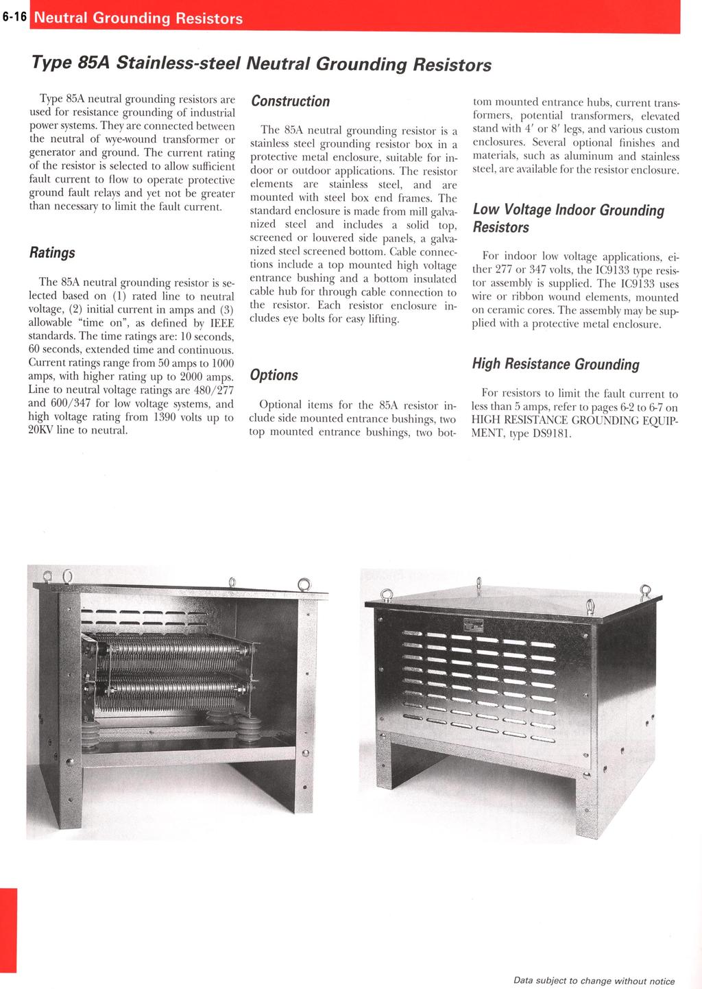
17 Type 85A Stainless-steel Neutral Grounding Resistors Neutral Grounding Resistors 6-17 Description Catalog Number 85A SYSTEM VOLTAGE L-N 1300 volts volts volts volts volts volts volts 100 TIME RATING 10 sec on time A extended time E continuous C 60 sec B 30 sec D CURRENT RATING 50 amps amps amps amps amps amps amps amps amps amps amps 2000 ENCLOSURE TYPE Mill finish Mx Painted finish Px Hot dip galvanized finish Hx Aluminum Ax Stainless steel Sx Standard enclosure xa Std enclosure with 4 ft stand xe Std enclosure with 6 ft stand xf Std enclosure with 8 ft stand xg BUSHINGS top bushing and bottom hub (basic version) 1 top bushing and bottom hub (w/terminals) 2 top and bottom bushings w/terminals 4 bottom entrance and exit with hubs 3 special per specifications 9 CURRENT TRANSFORMERS none NN 5kv CT Ax 8.5kv ct Bx 15kv ct Cx 100:5 xk 200:5 xm 300:5 xn 400:5 xp 600:5 xq 800:5 xr 1000:5 xs 1200:5 xt heater, anti-condensation Hx special per specification Yx OTHER MODIFICATIONS none none Special Customer Nameplate 2 Special Customer Drawings 3
18 6-18 Neutral Grounding Resistors Type 85A Stainless-steel Neutral Grounding Resistors Rating DIMENSIONS CATALOG NUMBER without CT with CT AMPS OHMS W D H W D H 1390 Volts line to neutral (2,400 volt system) 10 second rating A 13 A 50 MA 1NN A 13 A 100 MA 1NN A 13 A 200 MA 1NN A 13 A 300 MA 1NN A 13 A 400 MA 1NN A 13 A 500 MA 1NN A 13 A 600 MA 1NN A 13 A 800 MA 1NN A 13 A 1000 MA 1NN Volts line to neutral (4,160 volt system) 10 second rating A 24 A 50 MA 1NN A 24 A 100 MA 1NN A 24 A 200 MA 1NN A 24 A 300 MA 1NN A 24 A 400 MA 1NN A 24 A 500 MA 1NN A 24 A 600 MA 1NN A 24 A 800 MA 1NN A 24 A 1000 MA 1NN A 24 A 1200 MA 1NN Volts line to neutral (7,200 volt system) 10 second rating A 41 A 50 MA 1NN A 41 A 100 MA 1NN A 41 A 200 MA 1NN A 41 A 300 MA 1NN A 41 A 400 MA 1NN A 41 A 500 MA 1NN A 41 A 600 MA 1NN A 41 A 800 MA 1NN A 41 A 1000 MA 1NN A 41 A 1200 MA 1NN Volts line to neutral (13,900 volt system) 10 second rating A 80 A 50 MA 1NN A 80 A 100 MA 1NN A 80 A 200 MA 1NN A 80 A 300 MA 1NN A 80 A 400 MA 1NN A 80 A 500 MA 1NN A 80 A 600 MA 1NN A 80 A 800 MA 1NN A 80 A 1000 MA 1NN A 80 A 1200 MA 1NN
Grounding Systems. Resistance. Resistance Grounding Systems Contents
 Resistance Systems.0-1 Resistance Systems Contents Resistance Systems High Resistance System Medium Voltage...............1-1 High Resistance System Low Voltage..................2-1 Specifications See
A. Submit manufacturer's literature and technical data before starting work.
 SECTION 16425 SWITCHBOARD PART 1 GENERAL 1.01 SUMMARY A. Related Section: 1. 16450 - Grounding. 1.02 SUBMITTALS A. Submit manufacturer's literature and technical data before starting work. B. Submit Shop
Section SWITCHBOARDS. Introduction. Part 1 - General. Related Work
 Section 16435 - SWITCHBOARDS Introduction Part 1 - General Related Work Section 16070 Seismic Anchorage and Restraint Section 16075 Electrical Identification Section 16080 Power Distribution Acceptance
Medium Voltage Standby non-paralleling Control GUIDE FORM SPECIFICATION
 Medium Voltage Standby non-paralleling Control 1. GENERAL GUIDE FORM SPECIFICATION A. The requirements of the contract, Division 1, and part 16 apply to work in this section. 1.01 SECTIONS INCLUDE A. Medium
C1000 Series Automatic Cap Bank
 C1000 Series Automatic Cap Bank Metal Enclosed - Medium Voltage Capacitors Assemblies Fixed / Auto Medium Voltage 5, 15, 25 and 35 kv Class Customized to your specifications The Reactive Power Solution
Michigan State University Construction Standards SECONDARY UNIT SUBSTATIONS PAGE
 PAGE 261116-1 SECTION 261116 PART 1 - GENERAL 1.1 RELATED DOCUMENTS A. Drawings and general provisions of the Contract, including General and Supplementary Conditions and Division 01 Specification Sections,
Transformer Installation, Operation, and Maintenance Manual
 Transformer Installation, Operation, and Maintenance Manual CONTENTS INTRODUCTION......................................... 2 INSPECTION UPON RECEIVING... 2 STORAGE...............................................
A system fault contribution of 750 mva shall be used when determining the required interrupting rating for unit substation equipment.
 General Unit substations shall be 500 kva minimum, 1500 kva maximum unless approved otherwise by the University. For the required configuration of University substations see Standard Electrical Detail
Switchgear Skid, C1192
 CUSTOM SOLUTIONS 15kV Modular Stairs stored on floor in front of battery bay Ground grid stored on front tongue of trailer Stairs deployed for unit access Storage box for fencing materials and other parts
SECTION MOTOR CONTROL
 SECTION 26 24 19 MOTOR CONTROL PART 1 - GENERAL 1.1 SECTION INCLUDES A. Manual motor starters B. Magnetic motor starters C. Combination magnetic motor starters D. Solid-state reduced voltage motor starters
Horizontal Circuit Switchers
 > Transformer Protection > CIRCUIT SWITCHERS C A T A L O G B U L L E T I N General Application Southern States Types CSH and CSH-B Horizontal Circuit Switchers provide an economical, versatile, space saving
ME Switchgear with Vacuum Circuit Breaker and Auto-jet II Switch with Ground Position
 LET S BE PACIFIC November 0 Volume Number 5 ME Switchgear with Vacuum Circuit Breaker and Auto-jet II Switch with Ground Position Federal Pacific has the capability to engineer, fabricate and assemble
Horizontal Circuit Switchers
 > Transformer Protection > CIRCUIT SWITCHERS C A T A L O G B U L L E T I N General Application Southern States Types CSH and CSH-B Horizontal Circuit Switchers provide an economical, versatile, space saving
Indoor or Outdoor 2400 to 14,400 Volts 600 to 14,400 Kvac, 3 Phase, 60 Hz
 c February, 1979 Supersedes DB 39-485, pages 1-4, dated November, 1973 Mailed to: E, D, C/2001, 2002/DB Benefits There are many capacitor applications in which factors such as physical location, personnel
7. SERVICES OVER 600 VOLTS
 7. SERVICES OVER 600 VOLTS 7.1 GENERAL The Company shall always be consulted to obtain required design criteria where service is contemplated.preliminary plans of the Customer shall be submitted for review
CONTROLLIX CORPORATION CONTROLLIX.COM LOW VOLTAGE AUTOMATIC SWITCH CAPACITOR BANK SPECIFICATIONS
 LOW VOLTAGE AUTOMATIC SWITCH CAPACITOR BANK SPECIFICATIONS I. SCOPE a. This specification describes the necessary requirements for the design, fabrication, and operation of automatically switched, low
A. This Section includes ac, enclosed controllers rated 600 V and less, of the following types:
 SECTION 262913 600 VOLT ENCLOSED CONTROLLERS PART 1 - GENERAL 1.1 RELATED DOCUMENTS A. Drawings and general provisions of the Contract, including General and Supplementary Conditions and Division 0 Specification
SUBSTATION VACUUM CIRCUIT BREAKER (15.5KV)
") SUBSTATION VACUUM CIRCUIT BREAKER (15.5KV) For more than four decades, Myers Power Products has led the switchgear market in quality for the electric industry, delivering highly reliable products for utilities
SUBSTATION VACUUM CIRCUIT BREAKER (15.5KV) For more than four decades, Myers Power Products has led the switchgear market in quality for the electric industry, delivering highly reliable products for utilities
SUBSTATION VACUUM CIRCUIT BREAKER (25.8 / 27KV)
") SUBSTATION VACUUM CIRCUIT BREAKER (25.8 / 27KV) For more than four decades, Myers Power Products has led the switchgear market in quality for the electric industry, delivering highly reliable products
SUBSTATION VACUUM CIRCUIT BREAKER (25.8 / 27KV) For more than four decades, Myers Power Products has led the switchgear market in quality for the electric industry, delivering highly reliable products
SUBSTATION VACUUM CIRCUIT BREAKER (38KV)
") SUBSTATION VACUUM CIRCUIT BREAKER (38KV) For more than four decades, Myers Power Products has led the switchgear market in quality for the electric industry, delivering highly reliable products for utilities
SUBSTATION VACUUM CIRCUIT BREAKER (38KV) For more than four decades, Myers Power Products has led the switchgear market in quality for the electric industry, delivering highly reliable products for utilities
Solid Dielectric Load Break Switch SPECIFICATION. 25kV, 630A, 4 WAYS, 4 WAYS SWITCHED PADMOUNTED VACUUM LOAD INTERRUPTER
 Solid Dielectric Load Break Switch SPECIFICATION 25kV, 630A, 4 WAYS, 4 WAYS SWITCHED PADMOUNTED VACUUM LOAD INTERRUPTER MANUALLY OPERATED / REMOTELY OPERATED DEAD FRONT PADMOUNTED VACUUM LOAD INTERRUPTING
AIR CORE REACTORS. Phoenix Electric Corporation
 AIR CORE REACTORS Phoenix Electric Corporation PHOENIX ELECTRIC CORPORATION designs and manufactures Dry Type Air Core Reactors for operation on systems rated through 800 kv. All reactors are custom designed
A. This Section includes Low Voltage Switchgear Work, as indicated on the drawings, and as specified herein.
 16425 SWITCHBOARD ************************************************************************************************************* SPECIFIER: CSI MasterFormat 2004 number: 26 24 13 An optional keynote to
A. Three-phase, oil filled self-cooled, padmounted transformers are installed outdoors on pads in the EWEB distribution system.
 1. APPLICATION A. Three-phase, oil filled self-cooled, padmounted transformers are installed outdoors on pads in the EWEB distribution system. 2. REFERENCE STANDARDS A. The transformers supplied shall
Specifications. S&C Power Fuses Types SM and SMLa. For use with SM Refill Units or SMU Fuse Units. Indoor Distribution (4.16 kv through 34.
 S&C Power Fuses s SM and SMLa Indoor Distribution (4.16 through 34. ) For use with SM Refill Units or SMU Fuse Units Specifications Conditions of Sale STANDARD: Seller s standard conditions of sale set
TRI-SERVICE ELECTRICAL WORKING GROUP (TSEWG) 03/05/09 TSEWG TP-11: UFC N BEST PRACTICES
 03/05/09 TSEWG TP-11: UFC N BEST PRACTICES") TSEWG TP-11: UFC 3-500-10N BEST PRACTICES UFC 3-500-10N was developed by NAVFAC and was used as the starting point for the tri-services development of UFC 3-500-10, Design: Electrical Engineering. UFC
TSEWG TP-11: UFC 3-500-10N BEST PRACTICES UFC 3-500-10N was developed by NAVFAC and was used as the starting point for the tri-services development of UFC 3-500-10, Design: Electrical Engineering. UFC
GE 8000-Line Motor Control Centers
 GE 8000-Line -1 ENCLOSURE TYPES TYPE 1 General Purpose, Indoor Intended for use indoors, primarily to prevent accidental contact of personnel with the enclosed equipment, in areas where unusual service
Quick Start Guide TS 910
 Quick Start Guide TS 910 DANGER HAZARD OF ELECTRICAL SHOCK, EXPLOSION, OR ARC FLASH Read and understand this quick start guide before installing and operating the transfer switch The installer is responsible
Unit Substation Transformers 5 and 15 KV Class
 Transformers 5 and 15 KV Class 85 General Information Description Federal Pacific unit substation transformers are available in a wide variety of types and ratings to provide reliable and versatile electrical
SECTION ENCLOSED SWITCHES AND CIRCUIT BREAKERS
 SECTION 26 28 16 ENCLOSED SWITCHES AND PART 1 - GENERAL 1.1 SUMMARY A. Section includes the following individually mounted, enclosed switches and circuit breakers rated 600V AC and less: 1. Fusible switches.
2000 Cooper Bussmann, Inc. Page 1 of 9 10/04/00
 DO YOU KNOW THE FACTS ABOUT SINGLE-POLE INTERRUPTING RATINGS? YOU MAY BE IN TROUBLE! Typical plant electrical systems use three-phase distribution schemes. As an industry practice, short-circuit calculations
Volt Instrument Transformers
 www. kuhlman. com Kuhlman Electric Corporation Instrument Transformers 1 Table of Contents Description Model Page Wound, Oil-Filled VT (High Accuracy available) UTE-145-OH 3-4 Wound, Oil-Filled CCVT (High
INSTRUCTION BOOK SYSTEM 2001 GROUNDING EQUIPMENT FOR FAULT LOCATION. W/ High Resistance Neutral Grounding. for use on
 PCIB-1031 INSTRUCTION BOOK SYSTEM 2001 GROUNDING EQUIPMENT FOR FAULT LOCATION W/ High Resistance Neutral Grounding for use on 480 VOLT 3 PHASE 60HZ UNGROUNDED SYSTEMS WARNING FOLLOW THE SAFETY INSTRUCTIONS
Design Standard. Purpose: Design Standard:
 Design Standard Purpose: This design standard has the purpose of creating a consistent application of motor-control centers throughout the East Side Union High School District, therefore achieving a standard
Quick Start Guide TS 910 & TS 920
 Quick Start Guide TS 910 & TS 920 DANGER HAZARD OF ELECTRICAL SHOCK, EXPLOSION, OR ARC FLASH Read and understand this quick start guide before installing and operating the transfer switch The installer
Metal-enclosed medium-voltage power factor correction system
 Technical Data TD02607011E Supersedes June 2011 Metal-enclosed medium-voltage power factor correction system Contents Description Page Medium-voltage power factor correction... 1 Product description...
OTEC Transfer switch open transition
 Specification sheet OTEC Transfer switch open transition 40 1200 amp Description OTEC transfer switches are designed for operation and switching of electrical loads between primary power and Standby generator
University of Houston Master Construction Specifications Insert Project Name
 SECTION 26 13 13 MEDIUM VOLTAGE SWITCHGEAR PART 1 - GENERAL 1.1 RELATED DOCUMENTS: A. The Conditions of the Contract and applicable requirements of Divisions 0 and 1 and Section 26 00 01, Electrical General
2018 Consultant s Handbook Division 26 Electrical 2413 Switchboards
 1 General 1.1 Switchboards shall be U.L. listed and labeled. 1.2 Each switchboard shall have its own main disconnecting means unless it is located in the same room as its source of origin. In most cases
Technical Specification for Pole Mounted Capacitor Rack
 Technical Specification for Pole Mounted Rack Page 1 1. Scope and Function a) Pole mounted capacitor racks shall be installed on a distribution feed as an economical means of applying capacitor units to
Medium Voltage Metal-Enclosed Switches
 Medium Voltage Metal-Enclosed Switches Outdoor Medium Voltage Switch.1 Introduction Product Selection Guide....................................2 Medium Voltage Switch MVS Product Description......................................
Generator Fire Safety: Generator assemblies should be located outside the building.
 SECTION 33 70 00 - ELECTRICAL DISTRIBUTION PACKAGED GENERATOR ASSEMBLIES Generator Fire Safety: Generator assemblies should be located outside the building. All fuel piping from the outside of the building
Specifications. S&C Alduti-Rupter Switches with Power Fuses Outdoor Distribution (14.4 kv through 46 kv)
") Outdoor Distribution (4.4 kv through 46 kv) Specifications Conditions of Sale STANDARD: Seller s standard conditions of sale set forth in Price Sheet 50 apply, except as modified under WARRANTY QUALIFICATIONS
Outdoor Distribution (4.4 kv through 46 kv) Specifications Conditions of Sale STANDARD: Seller s standard conditions of sale set forth in Price Sheet 50 apply, except as modified under WARRANTY QUALIFICATIONS
Drive Duty Transformer Specification Virginia Transformer Corp. Power Up! Selecting the Right Transformer
 Drive Duty Transformer Specification Virginia Transformer Corp. Power Up! Selecting the Right Transformer This document contains sample specifications for Liquid-Filled Type Drive Transformers You may
SECTION ENCLOSED CONTROLLERS
 SECTION 16420 ENCLOSED CONTROLLERS PART 1 - GENERAL 1.1 RELATED DOCUMENTS A. Drawings and general provisions of the Contract, including General and Supplementary Conditions and Division 1 Specification
Medium Voltage Metal-Enclosed Switches
 Medium Voltage Metal-Enclosed Switches Outdoor Medium Voltage Switch.1 Medium Voltage Switch MVS Product Description............................................. 2 Application Description..........................................
M T E C o r p o r a t i o n. MTE Series RL. Line/ load Reactors USER MANUAL PART NO. INSTR -011 REL MTE Corporation
 M T E C o r p o r a t i o n MTE Series RL Line/ load Reactors USER MANUAL PART NO. INSTR -011 REL. 050516 2002 MTE Corporation IMPORTANT USER INFORMATION NOTICE MTE Series RL Line/Load Reactors are components
Technical Specification For Outdoor Substation Harmonic Filter Banks
 Technical Specification For Outdoor Substation Harmonic Filter Banks One of Three 5th, 11th & 23rd, 34.5 kv, Rated Harmonic Filter Assemblies Provided for a Central Venezuela Heavy Oil Production Field
IN2 Enclosed Switches and Circuit Breakers
 Illinois Math and Science Academy DigitalCommons@IMSA Project Manuals IN2 2015 IN2 Enclosed Switches and Circuit Breakers Illinois Mathematics and Science Academy Follow this and additional works at: http://digitalcommons.imsa.edu/facility_in2_manuals
CLARK PUBLIC UTILITIES TECHNICAL SPECIFICATIONS THREE-PHASE PADMOUNTED TRANSFORMERS
 CLARK PUBLIC UTILITIES TECHNICAL SPECIFICATIONS THREE-PHASE PADMOUNTED TRANSFORMERS Originated 1/85 Revised 6/95 Revised 6/02 Revised 11/05 Revised 4/08 Revised 11/09 Revised 1/12 Revised 11/12 Revised
SECTION 500 METERING AND ASSOCIATED EQUIPMENT
 SECTION 500 METERING AND ASSOCIATED EQUIPMENT 500.0 General Meter sockets shall be provided, installed and maintained by Customer. When the ratings of meter sockets are exceeded, transockets shall be used.
5kV to 38kV, 630 Amp to 4000 Amp Indoor or Outdoor Application
 The most advanced Arc-Resistant Switchgear, designed and built to provide maximum safety in the event of an Internal Arcing Fault. 5kV to 38kV, 630 Amp to 4000 Amp Indoor or Outdoor Application Page 1
Three-Phase Pole Mounted Recloser
 Three-Phase Pole Mounted Recloser Page 1 of 8 Table of Contents 1 GENERAL... 3 2 CONSTRUCTION... 3-5 3 BUSHINGS... 5 4 LINE CONNECTOR... 5 5 TOOLS....5 6 NAMEPLATES..6 7 PAINT... 6 8 EXTERNAL HARDWARE
University of Houston Master Construction Specifications Insert Project Name SECTION ELECTRONIC VARIABLE SPEED DRIVES PART 1 - GENERAL
 SECTION 23 04 10 ELECTRONIC VARIABLE SPEED DRIVES PART 1 - GENERAL 1.1 RELATED DOCUMENTS: A. The Conditions of the Contract and applicable requirements of Division 1, "General Requirements", and Section
SECTION LOW VOLTAGE DISTRIBUTION EQUIPMENT
 SECTION 16400 LOW VOLTAGE DISTRIBUTION EQUIPMENT A. General 1. The University does not accept Series-Rated equipment for power distribution switchboards, distribution panels and branch circuit panelboards.
BGE STRATEGIC CUSTOMER ENGINEERING
 TABLE OF CONTENTS 1. GENERAL.. 2 2. BGE SUPPLY FEEDER.. 4 3. SWITCHGEAR ENCLOSURE AND ASSEMBLY... 5 4. SWITCHGEAR MANUFACTURERS.. 8 5. CIRCUIT BREAKER.. 8 6. SWITCHGEAR EQUIPMENT.... 10 7. MAIN AND GROUND
AIR COOLED RECTIFIER SPECIFICATION S-50-A
 SPECIFICATIONS AIR COOLED RECTIFIER Spec50a1 5JAN1999 SPECIFICATION S-50-A HIGH VOLTAGE SINGLE TRANSFORMER AIR COOLED RECTIFIER Standard output power range: 250 to 600 volts at 100 to 1,200 amperes TECHNICAL
ADVANTAGE MOTOR CONTROL CENTERS INSTALLATION AND MAINTENANCE MANUAL
 CUTLER-HAMMER I.B. 8922-1A MODEL A ADVANTAGE MOTOR CONTROL CENTERS INSTALLATION AND MAINTENANCE MANUAL TABLE OF CONTENTS PART DESCRIPTION PAGE 1 General Information 2 2 Receiving, Handling, & Storage 4
INSTRUCTION MANUAL. Type SWF. Sine Wave Filters 480 Volts, 60Hz. Page 1 of 14. April 15, 2010: updated capacitor UL File number)
") POWER QUALITY INSTRUCTION MANUAL Type SWF Sine Wave Filters 480 Volts, 60Hz April 15, 2010: updated capacitor UL File number) Page 1 of 14 Contents 1. Introduction & SAFETY 2. Theory of operation 3. Advantage
POWER QUALITY INSTRUCTION MANUAL Type SWF Sine Wave Filters 480 Volts, 60Hz April 15, 2010: updated capacitor UL File number) Page 1 of 14 Contents 1. Introduction & SAFETY 2. Theory of operation 3. Advantage
Pretest Module 24 Three-phase Service Entrance
 Pretest Module 24 Three-phase Service Entrance 1. What is the most widely used three-phase service entrance system? 2. What are the three most common voltage combinations for three-phase, four-wire systems?
Features, Benefits and Functions
 -8 Buck-Boost and Lighting Single- and Three-Phase February 007 Single- and Three-Phase Applications, 60 Hz Type EP Product Description Types EP, EPT Sand and Resin Encapsulated design. Suitable for indoor
Issued Revised Approved Reviewed October 31, 1984 October 22, 2002 J. Ross J. Fuller
 Number: 5344-1.1.311 Rev. 8 Portable Mine Power Centres Issued Revised Approved Reviewed October 31, 1984 October 22, 2002 J. Ross J. Fuller SCOPE This specification covers general material and design
MTE SERIES RLW. World REACTORS USER MANUAL PART NO. INSTR 030 REL MTE Corporation
 MTE SERIES RLW World REACTORS USER MANUAL PART NO. INSTR 030 REL. 090529 2009 MTE Corporation IMPORTANT USER INFORMATION NOTICE MTE Series RLW Line/Load Reactors are components designed to improve the
Type SDV6 distribution circuit breaker. Top performance - proven reliability. Answers for energy.
 Type SDV6 distribution circuit breaker Top performance - proven reliability Answers for energy. Table of contents Introduction 2-4 Type 3AH3 stored-energy operating mechanism 6 Vacuum interrupters 7 Ratings
Extensible Unit - VCE2a
 ELECTRICAL INDUSTRIAL COMPANY (EICo) LUCY SWITCHGEAR Extensible Unit - VCE2a (Sabre) Electrical Industrial Company (EICo) Lucy Switchgear Extensible Unit VCE2a Front Panel: ELECTRICAL INDUSTRIAL COMPANY
TEMPORARY ELECTRIC WIRING FOR CARNIVALS, CONVENTIONS, EXHIBITIONS, FAIRS AND SIMILAR USES
 INFORMATION BULLETIN / PUBLIC - ELECTRICAL CODE REFERENCE NO.: LAMC 93.0230 Effective: 3-24-69 DOCUMENT NO. P/EC 2002-006 Revised: 11-17-00 Previously Issued As: RGA #7-69 TEMPORARY ELECTRIC WIRING FOR
Low Voltage Switchgear Type WL Low Voltage Metal-Enclosed Switchgear
 13 Low Voltage Switchgear Siemens Type WL low voltage metal-enclosed switchgear is designed, constructed and tested to provide superior power distribution, power monitoring and control. At the heart of
SERIES G100 / G110 SPECIFICATION 15KV & 25KV SUBMERSIBLE & VAULT MOUNTED SF 6 -INSULATED VACUUM LOAD INTERRUPTING SWITCHES
 SERIES G100 / G110 SPECIFICATION 15KV & 25KV SUBMERSIBLE & VAULT MOUNTED SF 6 -INSULATED VACUUM LOAD INTERRUPTING SWITCHES MANUALLY OPERATED / REMOTELY OPERATED DEAD FRONT SUBMERSIBLE AND VAULT MOUNTED
A. Products shall be designed, manufactured, tested, and installed in compliance with the following standards:
 SECTION 26 29 13 ENCLOSED MOTOR CONTROLLERS PART 1 - GENERAL 1.1 RELATED DOCUMENTS: A. The Conditions of the Contract and applicable requirements of Divisions 0 and 1 and Section 26 00 01, Electrical General
Typical Specification
 Engineered to Order Built to Last Typical Specification VAULT VRPFI, TWO POSITION, ROTARY PUFFER SWITCHGEAR PART 1- GENERAL 1.1 DESCRIPTION A. The switch shall consist of manually operated load interrupting,
Transfer switch OTEC open or delayed transition
 Transfer switch OTEC open or delayed transition 40-1000 Amp Description OTEC transfer switches are designed for operation and switching of electrical loads between primary power and standby generator sets.
3.2. Current Limiting Fuses. Contents
 .2 Contents Description Current Limiting Applications................. Voltage Rating.......................... Interrupting Rating....................... Continuous Current Rating................ Fuse
CON EDISON EQUIPMENT
 CON EDISON EQUIPMENT Con Ed Navtech Size Volts Amps List Spec. Cat. No Description Price 205 N-205 10x10x5 100 $72.00 205 RTN-205 10x10x5 100 190.00 215 N-215 24x12x8 200 144.00 215 RTN-215 24x12x8 200
Metal-enclosed medium voltage power factor correction system
 Supersedes November 2008 Contents Description Page Medium voltage power factor correction... 1 Product description... 1 Application description.... 2 Benefits.... 2 Univar XV (5 kv class).... 3 Product
SECTION PANELBOARDS
 SECTION 16470 PANELBOARDS PART 1 - GENERAL 1.1 RELATED DOCUMENTS A. The general provisions of the contract including General and Special Conditions and General Requirements shall apply to all work under
Specifications. S&C Power Fuses Types SM- 4, SM-5, SMD-20, and SMD-40 Outdoor Distribution (4.16 kv through 34.5 kv)
") S&C Power Fuses Types SM- 4, SM-5, SMD-0, and SMD-40 Outdoor Distribution (4.16 kv through kv) For use with SM Refill Units or SMU Fuse Units Specifications Conditions of Sale STANDARD: The seller s standard
S&C Power Fuses Types SM- 4, SM-5, SMD-0, and SMD-40 Outdoor Distribution (4.16 kv through kv) For use with SM Refill Units or SMU Fuse Units Specifications Conditions of Sale STANDARD: The seller s standard
15-kV Wall-Mount Switchgear Three-Phase Indoor/Outdoor 600 Amp S&C Mini-Rupter Switch
 Page 1 2015 Kinked roof prevents standing moisture Glass reinforced barriers meet NEMA GPO-3 Standards 0.625" diameter copper ground bar Elliott air-insulated bushings accept IEEE Standard inserts and
www. ElectricalPartManuals. com SPECIFICATIONS Page 1 of 24 March 24, 2003
 Types SM-4, SM-5, SMD-20, and SMD-40 Outdoor Distribution (4.16 kv through kv) Conditions of Sale STANDARD: Seller s standard conditions of sale set forth in Price Sheet apply, except as modified under
Customer Requirements Downtown Secondary Network Service
 Application This standard describes the limitations and requirements for receiving service from the Tacoma Power secondary network system within the City of Tacoma downtown core area. In This Standard
SERIES 802 / 812 SPECIFICATION 15KV & 25KV PADMOUNTED LIQUID-INSULATED VACUUM LOAD INTERRUPTERS AND FUSE ASSEMBLIES
 SERIES 802 / 812 SPECIFICATION 15KV & 25KV PADMOUNTED LIQUID-INSULATED VACUUM LOAD INTERRUPTERS AND FUSE ASSEMBLIES MANUALLY OPERATED / REMOTELY OPERATED DEAD FRONT PADMOUNTED SWITCHGEAR WITH VACUUM LOAD
Longest Life Product for Electric Furnace Applications! 100,000 Operations No Routine Maintenance Required!
 DB 750-205 January 2007 Supercedes: December 2006 Now available with Vacuum Interrupter Monitor VBT Switch 15kV - 69kV VBU-T Switch 69kV - 230kV Longest Life Product for Electric Furnace Applications!
Data Bulletin. Ground-Censor Ground-Fault Protection System Type GC Class 931
 Data Bulletin 0931DB0101 July 2001 Cedar Rapids, IA, USA Ground-Censor Ground-Fault Protection System Type GC Class 931 09313063 GT Sensor Shunt Trip of Circuit Interrupter Window Area for Conductors GC
AGRICULTURAL UNDERGROUND SERVICE 500 HP OR LESS
 Prepared by: ABB1 AGRICULTURAL UNDERGROUND SERVICE 500 HP OR LESS 05619 Asset Type: Electric Metering Function: Design and Construction Issued by: Lisseth Villareal (LDV2) Date: 07-31-15 Rev. #10: This
Page 2 DS LOW VOLTAGE POWER CIRCUIT BREAKERS Digitrip Trip Unit Inside Wiring Guide Outside Wiring Guide Shutter Drawout Unit Position Indicator Escut
 Page 1 Supersedes Renewal Parts Data 33-790-1G pages 1-20 dated December, 1988 Mailed to: C, D, E/33-700 Westinghouse DS and DSL Low Voltage Power Circuit Breakers and Cell Parts Contents Pages DS Breaker
56-SDMS-07 REV. 01 SPECIFICATIONS FOR
 56-SDMS-07 REV. 01 SPECIFICATIONS FOR UNIT SUBSTATIONS UP TO 36 kv ALUMINUM TRANSFORMER ALUMINUM BUS BARS LVDP This specification is property of SEC and subject to change or modification without any notice
CHPC Transfer switch closed transition
 Specification sheet CHPC Transfer switch closed transition 125-800 Amp Description The Cummins series CHPC PowerCommand automatic transfer switch monitors the primary power source, signals the generator
Freedom FlashGard Motor Control Center Instruction Manual IM E
 Freedom FlashGard Motor Instruction Effective August 2008 Part Description Page 1 General Information..................... 2 2 Receiving, Handling and Storage........... 4 3 Installing Sections..........
L. Photo. Figure 2: Types CA-16 Relay (rear view) Photo. Figure 1: Types CA-16 Relay (front view)
 Photo. Figure 1: Types CA-16 Relay (front view)") Figure 1: Types CA-16 Relay (front view) Photo Figure 2: Types CA-16 Relay (rear view) Photo 2 Sub 5 185A419 Sub 6 185A443 Figure 3: Internal Schematic of the Type CA-16 bus Relay or CA-26 Transformer
Figure 1: Types CA-16 Relay (front view) Photo Figure 2: Types CA-16 Relay (rear view) Photo 2 Sub 5 185A419 Sub 6 185A443 Figure 3: Internal Schematic of the Type CA-16 bus Relay or CA-26 Transformer
Power System Solutions (PSS)
") About Power System Solutions mission The Power System Solutions Mission Statement To achieve customer satisfaction by providing innovative solutions to improve upon power quality, energy efficiency, and
About Power System Solutions mission The Power System Solutions Mission Statement To achieve customer satisfaction by providing innovative solutions to improve upon power quality, energy efficiency, and
Guide Specification. Three-Phase Solid Dielectric Trident-SR with SafeVu Integral Visible Break
 Part 1-GENERAL 1.1 DESCRIPTION Guide Specification Three-Phase Solid Dielectric Trident-SR with SafeVu Integral Visible Break The switchgear shall consist of magnetically actuated solid dielectric insulated
SWITCHGEAR DIVISION PRODUCT PROFILES
 SWITCHGEAR DIVISION PRODUCT PROFILES Metal-Enclosed Load-Interrupter Switchgear Product Profiles Three-Phase, Group-Operated Load-Interrupter Switches with Fuses in Single and Multi-Bay Assemblies Manual,
MAGNETIC MOTOR STARTERS
 Chapter 6 MAGNETIC MOTOR STARTERS 1 The basic use for the magnetic contactor is for switching power in resistance heating elements, lighting, magnetic brakes, or heavy industrial solenoids. Contactors
VOLUME: IIIC SCHEDULE IIIC/4 11 KV AND 3.3 KV SWITCHGEARS
 VOLUME: IIIC SCHEDULE IIIC/4 11 KV AND 3.3 KV SWITCHGEARS A. 11 KV SWITCHGEAR 1.0 SWITCHGEAR ASSEMBLY 1.1 Make : 1.2 Type : 1.3 Reference Standard : 1.4 Voltage (Nom./Max.) KV : 1.5 Phase, Frequency No,Hz.
A. Work Included: Provide low voltage switchboard work as shown, scheduled, indicated, and as specified.
 SECTION 26 24 13 LOW VOLTAGE SWITCHBOARDS PART 1 - GENERAL 1.1 RELATED DOCUMENTS: A. The Conditions of the Contract and applicable requirements of Divisions 0 and 1 and Section 26 00 01, Electrical General
43-SDMS-04 REV. 00 SPECIFICATIONS FOR
 43-SDMS-04 REV. 00 SPECIFICATIONS FOR SHUNT CAPACITOR BANK 13.8 kv THROUGH 69 kv FOR PRIMARY DISTRIBUTION SUBSTATIONS This specification is property of SEC and subject to change or modification without
9. Non-Residential Services (Commercial, Industrial, and Agricultural)
") Section 9 2016 Electric Service Requirements, 3rd Edition Section 9 Non-Residential Services Directory Page 9.1 General Requirements 68 9.2 Direct-Connect Metering, Single Installations 69 9.3 Direct-Connect
Section 9 2016 Electric Service Requirements, 3rd Edition Section 9 Non-Residential Services Directory Page 9.1 General Requirements 68 9.2 Direct-Connect Metering, Single Installations 69 9.3 Direct-Connect
Publication No.: PSG
 TABLE OF CONTENTS PAGE 1.0 SCOPE...2 2.0 STANDARDS...2 3.0 DESIGN REQUIREMENTS...2 3.01 Service Conditions... 2 3.02 Ratings... 3 3.03 Resistors... 3 3.04 Interrupter... 4 3.05 SF 6 Gas System... 4 3.06
Kuhlman Electric Corporation Volt Instrument Transformers
 Kuhlman Electric Corporation 46000 Volt Instrument Transformers 46000 Volt Table of Contents Description Model Page Wound, Dry-Type VT (High Accuracy available) U/VRU-52(H) 3-4 Wound, Oil-Filled VT (High
35-kV Safefront SuperWell Mini-Switch Source Isolated Pad-Mounted Switchgear 50 Amp (Max) Clip-Mounted Current Limiting Fuses
 Clip-Mounted Current Limiting Fuses") Page 1 2016 EPMR-35-311S-R2/ESW-CM9 Three Phase Two Ways per Phase 200 Amp 35 kv Class Eaton s CPS LRTPs 50 Amp (Max) 27 kv Clip-Mounted NX Fuse Provisions 21.1/36.6 kv Grounded Wye Max Design, 150 kv
Page 1 2016 EPMR-35-311S-R2/ESW-CM9 Three Phase Two Ways per Phase 200 Amp 35 kv Class Eaton s CPS LRTPs 50 Amp (Max) 27 kv Clip-Mounted NX Fuse Provisions 21.1/36.6 kv Grounded Wye Max Design, 150 kv
Metal-Enclosed Switches. Medium Voltage. Medium Voltage Metal-Enclosed Switches Contents
 January 2003 Vol. 1, Ref. No. [1011] -1 Medium Voltage Metal-Enclosed Switches Contents Description Page MVS................................... -2 and Breaker MSB........................ -3 Metal-Enclosed