2 - HANDLING AND HOISTING COMMISSIONING...5
|
|
|
- Erica Craig
- 6 years ago
- Views:
Transcription
1 Contents Instructions for use Page I 1- GENERAL GENERAL SAFETY RECOMMENDATIONS STANDARD SAFETY DEVICES FIELD OF APPLICATION OVERALL DIMENSIONS SPECIFICATION HANDLING AND HOISTING COMMISSIONING ANCHORING ELECTRICAL CONNECTION PNEUMATIC CONNECTION (Versions P) EXTRA SAFETY DEVICES (VERSION P) ADAPTER MOUNTING...5 SE2 MOUNTING...6 SE2 DISMOUNTING GUARD MOUNTING AND ADJUSTMENT SPACER WD CONTROLS AND COMPONENTS BRAKE PEDAL PNEUMATIC LOCKING PEDAL (Version P) AUTOMATIC DISTANCE AND DIAMETER GAUGE AUTOMATIC WIDTH GAUGE (OPTION) AUTOMATIC WHEEL POSITIONING KEYBOARD INDICATIONS AND USE OF THE WHEEL BALANCER INITIAL SCREEN SCREEN-SAVE SCREEN MENU ACCESS DIAGRAM PRESETTING OF WHEEL DIMENSIONS AUTOMATIC PRESETTING STEEL OR ALUMINUM WHEEL RIMS. SPRUNG COUNTERWEIGHTS AUTOMATIC WIDTH MEASUREMENT (OPTIONAL) ALU AND STATIC MODES RIMS WITH INTERNAL COUNTERWEIGHT USER CONTROL USER MEMORIZATION TO CALL USER RESULT OF MEASUREMENT INDICATION OF EXACT CORRECTION WEIGHT POSITION SPLIT CONTROL UNBALANCE OPTIMIZATION TO CANCEL STATIC UNBALANCE ECCENTRICITY MEASUREMENT (OPTIONAL) SETUP LANGUAGE UNIT OF UNBALANCE MEASUREMENT UNBALANCE DISPLAY THRESHOLD UNBALANCE DISPLAY PITCH SPIN WITH GUARD CLOSED SCREEN-SAVER TIME VISUAL ECCENTRICITY CHECK ACOUSTIC SIGNAL ECCENTRICITY MEASUREMENT UNIT FIRST HARMONIC LIMIT MANUAL PRESETTING STEEL WHEEL RIMS RIMS WITH INTERNAL COUNTERWEIGHTS (ALU S)...25 WARNING 7 - SPECIAL CALIBRATIONS AND FUNCTIONS ENABLING OF WIDTH MEASUREMENT ENABLING OF ECCENTRICITY MEASUREMENT (OPTION) PRESETTING THE CUSTOMER AND USER NAME CALIBRATIONS GAUGE CALIBRATION WHEEL BALANCER CALIBRATION ROOM TEMPERATURE MACHINE SELF-TEST TO CHECK THE ENCODER CONTROL OF SERIAL OUTPUT RS232C (OPTIONAL) ERRORS...28 I 0355 GB - 1
2 9 - ROUTINE MAINTENANCE TO REPLACE THE FUSES RECOMMENDED SPARE PARTS LIST...30 I 0355 GB - 2
3 1 - General General safety recommendations - The balancing machine should only be used by duly authorized and trained personnel. - The balancing machine should not be used for purposes other than those described in the instruction manual. - Under no way should the balancing machine be modified except for those modifications made explicitly by the manufacturer. - Never remove the safety devices. Any work on the machine should only be carried out by duly authorized specialist personnel. - Do not use strong jets of compressed air for cleaning. - Use alcohol to clean plastic panels or shelves (AVOID LIQUIDS CONTAINING SOLVENTS). - Before starting the wheel balancing cycle, make sure that the wheel is securely locked on the adapter. - The machine operator should not wear clothes with flapping edges. Make sure that unauthorized personnel do not approach the balancing machine during the work cycle. - Avoid placing objects in the base which could impair the correct operation of the balancing machine Standard safety devices - STOP push button for stopping the wheel under emergency conditions. - The safety guard of high impact plastic is with shape and size designed to prevent risk of counterweights from flying out in any direction except towards the floor. - A microswitch prevents starting the machine if the guard is not lowered and stops the wheel whenever the guard is raised Field of application The machine is designed for balancing car or motorcycle wheels weighing less than 75 kg. It can be operated within a temperature range of 0 to +45 C. It can measure the geometric radial run-out of the wheels (optional) Overall dimensions (42") I 0355 GB - 3
4 1.4 - Specification Weight with guard (excluding adapter) Kg Single phase power supply V Hz Protection class... IP 54 Max. power consumption... 1,1 Kw Monitor... SVGA 15 Balancing speed r.p.m. Cycle time for average wheel (14 kg)... 6 seconds Balancing accuracy... 1 gram Position resolution... ± 1.4 Average noise level... < 70 db(a) Distance rim - machine mm Rim width setting range or mm Diameter setting range or mm Total wheel diameter within guard mm (standard) mm (42 ) Total wheel width within guard mm (standard) mm (42 ) Min/max. compressed air pressure Kg/cm² MPa BAR PSI 2 - Handling and hoisting 2 2a N.B.: DO NOT HOIST THE MACHINE USING OTHER LIFTING POINTS. I 0355 GB - 4
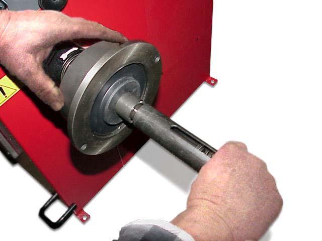
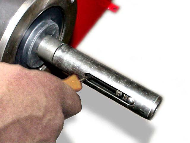
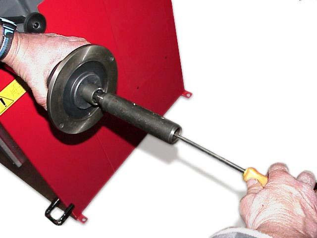
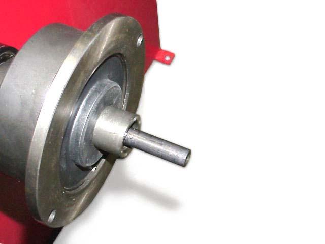
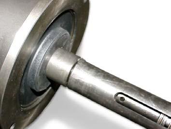
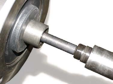
5 3 - Commissioning Anchoring The machine can be operated on any flat non-resilient floor. Make sure that the machine rests solely on the three support points provided (fig. 2a). It is advisable to secure the machine to the ground in the event of continual use with wheels weighing over 35 Kg Electrical connection The machine is supplied with a single phase mains cable plus earth (ground). The supply voltage (and mains frequency) is given on the machine nameplate. It may not be changed. Connection to the mains should always be made by expert personnel. The machine should not be started up without proper earth (ground) connection. Connection to the mains should be through a slow acting safety switch rated at 4A (230V) or 10A (115V) Pneumatic connection (versions P) For operation of the spindle with pneumatic locking (costant thrust air spring) connect the balancing to the compressed air main. The connection fitting is located at the back of the machine. At least 7 Kg/cm 2 (~ 0.7 MPa; ~ 7 BAR; ~ 100 PSI) pressure is needed for correct operation of the release device Extra safety devices (version P) - Wheel always locked even when there is pressure failure during the balancing cycle. - Always actuate the unlocking control pedal with the machine stationary in order to avoid stress and abnormal wear on the adapter Adapter mounting The balancing machine is supplied complete with cone adapter for fastening wheels with central bore. Other optional flanges can be mounted once the terminal part is removed (also see enclosed brochures) N.B.: Carefully clean the coupling surfaces before performing any operation DISMOUNTING THREADED END PIECE (standard spindle) 3 A B a) Back-off screw B and remove threaded end-piece A. b) Fit the new adapter. I 0355 GB - 5
6 1-2 mm SE2-Mounting 0 mm a b c d e f g SE2_ 0140


7 SE2-Dismounting 360 a b c d Cone e - Quando possibile, centrare le ruote con cono dall'interno (vedi disegno). - Evitare di usare il manicotto RL con cerchi di ferro. - Whenever possible, centre the wheels with the cone from the inside (see the drawing). - Avoid using the RL sleeve with metal rims. - Lorsque c est possible, centrer les roues avec le cône de l intérieur (voir dessin). - Eviter d utiliser le manchon RL avec les jantes en fer. - Wenn möglich, die Räder mit Konus von Innen heraus zentrieren (siehe Zeichnung). - Bei Eisenfelgen die Verwendung der Muffe RL vermeiden. - Siempre que sea posible, centrar las ruedas con cono desde dentro (véase dibujo). - Evitar usar el manguito RL con llantas de hierro. SE2_ 0140
8 3.6 - Guard mounting and adjustment a) Fasten the components to the base as illustrated in specific exploded view. b) The position of the wheel guard when closed can be adjusted with relative screw accessible at the back. Correct position is horizontal with guard closed. c) Check that the microswitch is held down when the guard is closed. d) Adjust the angular position of microswitch control Spacer WD When balancing very wide wheels (9 ), there is not enough space to turn the distance gauge. To withdraw the wheel from the machine side, fit spacer WD on the adapter body and secure it with the standard issue nuts. When centring the wheel with the cone on the inside, fit the spacer DC to obtain spring thrust. 5 DC WD Spring Cone I 0355 GB - 8
9 4 - Controls and components Brake pedal 6 This pedal allows the operator to hold the wheel when fitting the counterweights. It must not be actuated during the measuring cycle Pneumatic locking pedal (Version P) 7 This pedal allows releasing the device fastening the wheel on the adapter. Do not actuate this pedal during the machine cycle and/or when adapters other than the standard cone adapter are mounted. The pedal has two stable positions: top, wheel unclamped; bottom, wheel clamped Automatic distance and diameter gauge This gauge allows measurement of the distance of the wheel from the machine and the wheel diameter at the point of application of the counterweight. It also allows correct positioning of the counterweights inside rim by using the specific function (see INDICATION OF EXACT CORRECTION WEIGHT POSITION) which allows reading, on the monitor, the position used for the measurement inside the rim (For calibration, see GAUGE CALIBRATION) Automatic width gauge (option) Width gauging is through a SONAR device which measures the distance of the wheel without mechanical contact, merely by closing the guard and each time a valid measurement has been made with gauge DISTANCE AND DIAMETER GAUGE Automatic wheel positioning At the end of the spin, the wheel is positioned according to the unbalance on the outside or else according to the static unbalance (when selected). Positioning is disabled automatically for wheels less than 13 in diameter. Accuracy is ± 20 degrees for wheels weighing up to 25 kg. I 0355 GB - 9
10 4.6 - Keyboard 8 FUNCTION KEYS: they immediately select function indicated on the monitor selection of special confirm starts measuring cycle interrupts machine cycle NB : - Press the buttons with the fingers only: never use the counterweight pincers or other pointed objects. - When the beep signal is enabled (see section ACOUSTIC SEGNAL), pressing of any push button is accompanied by a beep. I 0355 GB - 10
 : type of correction (see ALU AND STATIC MODES) : balancing spin (see RESULT OF MEASUREMENT) Dimensions gauge:")
11 5 - Indications and use of the wheel balancer The monitor shows several information and suggests various alternative ways of use to the operator. This is done through various screens Initial screen Buttons enabled : main functions screen (see MENU ACCESS DIAGRAM) : type of correction (see ALU AND STATIC MODES) : balancing spin (see RESULT OF MEASUREMENT) Dimensions gauge: when extracted, the Dimensions screen is selected (see PRESETTING OF WHEEL DIMENSIONS). If the machine remains on the initial screen for a certain amount of time without being used, the system is automatically switched to a screen-save. Striking of any key, movement of the wheel or distance + diameter gauge will cause automatic switching from the screen-save menu to the initial screen. From the screen-save, the automatic start actuated by the guard is not available for safety reasons Screen-save screen N.B.: Name of the wheel balancer s owner. Can be preset via the monitor. I 0355 GB - 11


12 5.2 - Menu access diagram N.B. : - The symbol indicates the presence of a further menu - To return to the previous menu, press button - To return to the initial screen, press button Machine parameters set-up Language English Unbalance measuring unit Unbalance threshold Visualization step Start by wheel guard lowering Screensaver time More A User control B Abort Load user Save user Optimization Dimensions Set-up D Special functions G Abort Set-up machine parameters Visual Eccentricity check Acustic signal Eccentricity measuring unit 1st harmonic limit Previous C D Selections User control PASSWORD: RESERVED FOR EXPERT PERSONNEL Special functions Width measure Eccentricity measure Owner address Users names Calibration RS232 Abort Abort F E Sensors Calibrations Calibrations Distance Diameter Width Machine self-calibration Room temperature Machine test Abort Abort I 0355 GB - 12

13 5.3 - Presetting of wheel dimensions Automatic presetting The screen appears upon extracting the distance + diameter gauge. The indication dimension acquired is given by the symbol of the correction weight which changes from blue to red Steel or aluminum wheel rims. Sprung counterweights Using the special handle, move the tip of the gauge against the rim in one of the positions A/B shown in fig Hold the gauge still in position for at least 2 seconds. N.B. Always use the round part of the striking surface. 9 When the acoustic beep is enabled (see section ACOUSTIC SIGNAL), acquisition of the dimensions is accompanied by a beep. This calibration is valid for ALU 1, 2, 3, 4, CTS, Static and Dynamic modes. The current width value appears inside the tyre. POS. A POS. B I 0355 GB - 13
14 b - Preset the nominal width, which is normally stamped on the rim, or else measure the width b with the calliper gauge (standard accessory). The other enabled buttons are: - User recall/save management 9a - Press button to switch to manual setting of all wheel dimensions. - Press button to return to the Measurement screen. b 9b Automatic width measurement (optional) Gradually lower the guard after carrying out measurement of distance + diameter in automatic mode. If the width measured is incorrect (out of range), the following message appears: Sonar measure is out of range: F1 = repeat F2 = manual set-up Press F1 to re-lower the guard and repeat the width measurement. Press F2 to go to the dimensions panel for manual insertion of the width measurement. The calibration performed as such is necessary for modes AL1,2,3,4,CTS,Static, Dynamic. Manually presetting is possible by using the push buttons as described in MANUAL PRESETTING. Only for automatic width option: The key L.T. (LIGHT TRUCK) is used to improve the dimensional calibration of large wheels, such as off-road, trucks and wheels protrude significantly from the rim. Press the key L.T. after the distance measurement, immediately before lowering the width measurement guard. This option is disengaged at the end of the current width measurement. I 0355 GB - 14

15 Alu and static modes From the Measurement screen, press button : a window with the possible modes appears. Select the type required through the numeric keys. The return to the Measurement screen with the recalculated values is automatic. The enabled weight application position is always displayed inside the section of the circle. CORRECTION TYPE STATIC DYNAMIC STANDARD Balancing of steel or light alloy rims with application of clip-on weights on the rim edges. STATIC The STATIC mode is necessary for motorcycle wheels or when it is not possible to place the counterweights on both sides of the rim. ALU - 1 Balancing of light alloy rims with application of adhesive weights on the rim shoulders. ALU - 2 Balancing of alloy rims with hidden application of the adhesive weight on the outside. The position of the outside weight is fixed. 12/13 mm piano resting d'appoggio surface ALU - 3 Combined application: clip-on weight inside and hidden adhesive weight on the outside (Mercedes). Outside weight position is the same as ALU-2. ALU - 4 Combined application: clip-on weight the outside and hidden adhesive weight inside CTS Special balancing with snap-in adhesive weights between the edge of the tyre and rim, for both sides. I 0355 GB - 15
16 Rims with internal counterweight After measurement made on inside FI, as illustrated in fig. 10, move the gauge out further to memorize the data regarding the outside FE. Select position A or B in fig. 9 as required and hold the position for at least 2 seconds. The counterweight symbols change colour. When the acoustic beep is enabled (see section ACOUSTIC SEGNAL), acquisition of the dimensions is accompanied by a beep. 10 FI FE The following buttons are enabled: - User recall/save management - Selection of Manual dimensions setting screen / - Return to Initial screen - Balancing spin I 0355 GB - 16
. 5.4.")
17 5.4 - User control Save user Abort The wheel balancer can be used simultaneously by 4 different users who, through a simple sequence, can memorize their work condition and call it when needed. The users names can be memorized (PRESETTING THE CUSTOMER AND USER NAME) User memorization - Preset the dimensions correctly according to the procedures already described in section PRESETTING OF WHEEL DIMENSIONS. - Press ; the MENU window appears on the monitor - Press ; a window appears with the list of available USERS. The current USER is displayed in red. - Press the number corresponding to the required USER. The system returns to the initial screen automatically To call user - Perform a measuring spin with any dimensions. - Press button ; the MENU window appears on the screen. - Press : a window appears with the list of available USERS. The current user is displayed in red. - Press the number corresponding to the required USER. The system automatically returns to the initial screen with recalculation of the unbalance values on the basis of the effective dimensions of the USER called. N.B. - The dimensions memorized as USER are lost when the machine is switched off. - The USER control is also valid for the ALU-S dimensions. - The current USER is always displayed in the Measurement and Dimensions screens. I 0355 GB - 17
18 5.5 - Result of measurement After performing a balancing spin, the unbalance values are displayed as well as arrows useful for positioning the point of application of the correction weight. After positioning the wheel, apply the weight in the 12 o clock position. When the acoustic beep is enabled (see section ACOUSTIC SEGNAL), reaching of the correction position is indicated by a beep. If the unbalance is less than the chosen threshold value, the OK message appears instead of the unbalance value to indicate, on that particular side, the wheel is in tolerance; the residual unbalance can be displayed by pressing button with an accuracy of 0.5 g (0.1 oz). The following buttons are enabled : Display of residual unbalance. Selection of correction mode (DYNAMIC, STATIC, ALU1, ALU2, ALU3, ALU4, CTS). When the mode is changed, the unbalance values are recalculated automatically on the basis of the previous spin (ALU AND STATIC MODES). Eccentricity measurement graph (optional). The symbol above the key turns red if the first harmonic eccentricity exceeds the limit defined by setup parameters (see FIRST HARMONIC LIMIT). Split control for splitting of unbalance over presettable components ( SPLIT CONTROL). Button only enabled in STATIC or ALU S correction. Indication of the longitudinal position of the unbalance (INDICATION OF EXACT CORRECTION WEIGHT POSITION) is enabled For selection of special functions Balancing spin. N.B. : If the machine remains on this screen without being used for more than the time preset in the Setup parameters (6), the screen automatically returns to the screen-save I 0355 GB - 18

19 Indication of exact correction weight position It is recommended to always use this function when correcting the unbalance through adhesive weights: ALU S, STATIC, ALU 2, ALU 3. In all cases this function allows cancelling approximations in the mounting of counterweights with consequent reduction of the residual unbalance - Press button from the Measurement results screen. - Pull out the gauge in position A in fig Approach of the weight to the correction position is indicated by a moving coloured arrow [ ]. - When a fixed arrow [ ], is reached, rotate the wheel to correction position (FI or FE) and apply the counterweight by turning the pincers until they adhere to the wheel. - The position for application of the correction weights is automatically rephased according to the position of the distance + diameter gauge (position A in fig. 9). When the acoustic beep is enabled (see section ACOUSTIC SIGNAL), reaching of a fixed arrow [ ], arrow is indicated by a beep. 11 I 0355 GB - 19

20 Split control The SPLIT function is only possible in the case of static unbalance or ALU-S on the outside. It serves for concealing any stick-on unbalance correction weights behind the rim spokes. TO PRESET THE NUMBER OF RIM SPOKES - From the STATIC or ALU-S measurement screen, press ; - a window appears on the display indicating the currently preset number of spokes. - set the required number of spokes in the range 3 to 12 by pressing and - press to confirm the presetting - bring a spoke to the 12 o clock position. - press ; the Measurement Screen reappears with the unbalance values already split. The ALU-S unbalance on the inside does not vary while as regards the STATIC and ALU-S unbalance on the outside two weights appears for the same side: - Gradually turn the wheel until an unbalance value appears. - Apply an adhesive weight of the value indicated on the screen for the outside or STATIC, behind the spoke in the 12 o clock position. - Again turn the wheel until a new unbalance value appears. - Apply an adhesive weight of the value indicated on the screen for the outside or STATIC, behind the spoke in the 12 o clock position. - Perform a spin to check for correct wheel balancing. N.B. : - When SPLIT is enabled, the icon appears at the bottom of the screen. - When the position repeat function (see INDICATION OF EXACT CORRECTION WEIGHT POSITION) is enabled, the weight application position is re-phased according to the position of the distance + diameter gauge (position A in fig. 9). I 0355 GB - 20

21 Unbalance optimization UNBALANCE OPTIMIZATION - Make sure that the previous spin was made with the wheel now fitted on the wheel balancer. - Trace the rim adaptor position with a reference mark to allow re-assembling on the adaptor in the same position. - Remove the wheel from the balancer - Turn the tyre 180 on the rim. - Re-assemble the wheel on the balancer by positioning the rim reference mark with the adaptor s. - Close the wheel guard and push (START). Abort The symbol is displayed automatically for static unbalance exceeding 30 grams (1.1 oz). The program allows reducing the total unbalance of the wheel by compensating, when possible, the unbalance of the tyre with that of the rim. It requires two spins with rotation of the tyre on the rim in the second spin. After performing a spin, press: + and follow the instructions appearing on the monitor To cancel static unbalance This function can be selected from the Setup screen. It serves for optimizing the residual unbalance by correcting a wheel with standard counterweights in steps of 5 grams (1/4 oz.). Thanks to this particular function, the position and best correction value are calculated in order to cancel the static unbalance: the main cause of the vibrations which can be felt inside the car. I 0355 GB - 21

22 5.6 - Eccentricity measurement (optional) The much enlarged figures show the outer tyre surface and axis of wheel rotation. Fig. A shows measurement of the total Peak-to-Peak eccentricity defined as maximum radial deviation of the tyre surface. Fig. B shows measurement of the eccentricity of the 1st harmonic, i.e. the eccentricity of that circle which recopies the tyre shape, by averaging the local deviations of the tyre from the round shape. Obviously the P.P. measurement is normally greater than that of the 1st harmonic. Tyre manufacturers normally supply two different tolerances for the two eccentricities. At the end of the balancing spin it is possible to automatically measure the eccentricity of the tyre through the SONAR sensor installed on the guard. The sensor should be positioned by hand in front of the tyre tread. V.p/p V. 1h V.actual GRAPH 1 : represents the actual Peak-to-Peak eccentricity. GRAPH 2 : represents the eccentricity of the 1st harmonic. For a wheel in optimum conditions, such graph should approach a straight line. When the wheel is moved, the cursor on the screen indicates the actual value, with the phase referred to the eccentricity measurement sensor. Note : eccentricity measure is valid for tyre with max mm Ø. I 0355 GB - 22
23 6 - Setup (See Diagram showing access to the menus) The Setup screen provides the user with many possibilities required for presetting the machine according to his own requirements. Such settings remain unaltered even when the machine is switched off. The following buttons are enabled: : return to previous window; : return to Measurement screen; from to : for selection of the parameter Language This function allows selecting the language to be used for displaying descriptive and diagnostic messages regarding machine operation Unit of unbalance measurement It is possible to select whether to display the unbalance values expressed in grams or ounces Unbalance display threshold This consists of the unbalance threshold below which the wording OK appears on the screen at the end of the spin instead of the unbalance; the presettable values vary according to the unit of measurement selected Unbalance display pitch This represents the display pitch of the unbalance and varies according to the unit of measurement selected. The selection 5 g (1/4 oz) enables display of the correction values on both sides such as to bring the static unbalance to 0 (theoretical). It is recommended to preset this function as standard use of the machine as it improves the balancing quality. The computer makes a complex calculation which allows cancelling the residual static unbalance by varying the value and position of the counterweights fixed in steps of 5 grams (1/4 oz) Spin with guard closed When ON is selected the automatic start of the spin is enabled upon closing the guard Screen-saver time When the machine remains unused for longer than the time preset with this function, the processor automatically returns to the Initial screen. Preset the time in seconds Visual eccentricity check At the end of wheel acceleration, as soon as the motor is disengaged, the guard can be opened for visual control of any wheel eccentricity as the rotation speed gradually drops. Do not strike the wheel during the entire deceleration stage; to brake the wheel, close the guard. However, avoid using the brake as far as possible because this may compromise unbalance measurements. The unbalance values measured are only displayed when the wheel has come to a standstill. This function is active for only one machine run Acoustic signal When ON is selected, an acoustic signal (beep) is given in the following cases: - when any button is pressed; - when dimensions are acquired in automatic mode - upon reaching the correct angular weight application position, in the Measurements screen; - upon reaching the correct weight application distance, in the Position repeat screen Eccentricity measurement unit It is possible to select display of eccentricity measurements in mm or inches First harmonic limit This is the first harmonic limit beyond which more detailed analysis of eccentricity is advisable. In the event of first harmonic eccentricity higher than the set limit, the symbol above the button for input in the eccentricity control panel ( ) turns red (recommended limit 1.2 mm/0.05 inch). I 0355 GB - 23
24 Manual presetting (Use only in special cases or for checking) Steel wheel rims (use for setting dimensions in AUTOCALIBRATION) Unit If necessary, the dimensions can be inserted or edited in manual mode as follows: - press + or else press from the Dimensions screen in automatic mode (which can be reached by pulling out the distance + diameter gauge); - press to select the dimension to be preset (highlighted in red); - press / to preset the required value; - press to change unit of measurement. - press to preset the dimensions for the ALUS correction mode. Definition of dimensions: = DIAMETER : Preset the nominal diameter stamped on the rim. = WIDTH : Preset the nominal width indicated on the rim. = DISTANCE : Set the wheel-machine distance in mm, and check with the special gauge as described in fig I 0355 GB - 24
25 Rims with internal counterweights (ALU S) Unit Also in the ALUS correction mode, the dimensions can be entered or edited manually. Use the buttons indicated on the monitor and follow the screen indicated by the graphics. To access the Manual presetting screen for ALUS dimensions, press: 1) CURRENT SETTING TYPE OF CORRECTION = ALUS + or else from the Dimensions screen in automatic mode (can be reached by pulling out the distance + diameter gauge). 2) CURRENT SETTING TYPE OF CORRECTION ALUS + + For a clearer understanding of what is displayed by the graphics, consult the following scheme: 12a 14 mm Distance reading - To return to the presetting screen for standard wheel dimensions, press button I 0355 GB - 25
26 - WARNING Special calibrations and functions (See ACCESS DIAGRAM) Any incorrect operation within the functions described below could impair the operation of the wheel balancing machine. Unauthorized use will cause cancellation of the warranty on the machine Enabling of width measurement (optional) This function enables/disables automatic width measurement with SONAR; select OFF under normal conditions and SONAR if the machine has provision for automatic width measurement Enabling of eccentricity measurement Enables/disables measurement of the tyre eccentricity during an unbalance measurement spin Presetting the customer and user name The machine can be customized by presetting: a) The name appearing on the Initial screen (screen-save). b) The name of 4 different machine users ( USER NAME). An ideal keyboard appears on the monitor with the set of characters available for composition of the wordings. The Customer s name consists of three lines, each max. 30 characters. The USER NAME consists of a wording max. 15 characters Calibrations When is pressed from the Special Functions menu, access is gained to the Calibration menu Gauge calibration Select the gauge to be calibrated and follow the instructions appearing on the monitor. N.B.: - In the width gauge calibration it is necessary to enter two dimensions which can be measured as follows: A - GAUGE ZERO DISTANCE SONAR ZERO DISTANCE Wheel balancer calibration For calibration of the machine, proceed as follows: - Use a medium-sized metal wheel. Example: 6 x 14 (± 1 ) - Preset the wheel dimensions with GREAT CARE. - Follow the instructions appearing on the monitor. I 0355 GB - 26

27 Ambient temperature Ambient temperature is important for correct use of the sonars. Set the average temperature of the area where the wheel balancer is installed Machine self-test An automatic self-diagnostics cycle is provided for easier trouble shooting. At the end of the self-diagnostics cycle, several parameters are displayed which are useful for the Technical Service Department in order to identify machine faults. Return to previous menu To check the encoder When the spindle is rotated: - the angular position POS should vary from 0 to 128; - the wording UP should appear when rotated clockwise and DOWN when rotated in the opposite direction. Encoder check Width FVB Check for correct operation of the diameter gauge; the number increases when the gauge is rotated outwards Check for correct operation of the distance gauge; the number increases when the gauge is pulled out. Abort Check of the eccentricity sonar (option): the number decreases when a surface is approached to the sonar. Check of the width sonar (option): the number decreases when a surface is approached to the sonar. In the event of failure or faulty operation of the wheel balancing machine, notify the Technical Service of all the parameters displayed Control of serial output RS232C (optional) Enables/disables sending of unbalance values and phases measured to serial output RS232C. Transmission speed = 9600 baud Data format = 1 bit Start 7 bit Data 1 bit Even parity 1 bit Stop At the end of each unbalance measuring spin, the balancing machine enables the RTS signal and then remains in wait for the $ character in order to transmit the data; all functions remain on hold until the transmission is enabled, at the end of which the RTS signal is given in the inactive status. Data transmitted via serial line are in ASCII format and are separated between each other with the <cr> character (0x0d). Send sequence is as follows: <cr> - Correction weight, left side <cr> - Correction phase, left side <cr> - Correction weight, right side <cr> - Correction phase, right side <cr> The first 5 bytes at zero represent the transmission start message. The correction values are expressed in grams with steps of 0.1 gram. The phase values are expressed in degrees in the range 0% 359 (See specific computer board on exploded drawings). I 0355 GB - 27

28 8 - Errors ERROR Nr Open guard ERRORS CAUSES CONTROLS Err. 1 No rotation signal. 1. Verify belt tautness. 2. Verify the function of the phase pick-up board and, in particular, the reset signal. 3. Replace the phase pick-up board. 4. Replace the computer board. Err. 2 Speed too low during detection. During unbalance measurement rotation, wheel speed is less than 42 rpm. 1. Make sure that a vehicle wheel is mounted on the wheel balancer. 2. Verify belt tautness. 3. Verify the function of the phase pick-up board and, in particular, the reset signal. 4. Replace the computer board. Err. 3 Unbalance too high. 1. Verify wheel dimension settings. 2. Check detection unit connections. 3. Perform machine calibration. 4. Mount a wheel with more or less known unbalance (less than 100 grammes) and verify the response of the machine. 5. Replace the computer board. Err. 4 Err. 5 Err. 7 / Err. 8 Rotation in opposite direction. After pressing [START], the wheel begins to rotate in the opposite direction (anticlockwise). Guard open The [START] pushbutton was pressed without first closing the guard. 1. Verify the connection of the UP/DOWN RESET signals on the phase pick-up board. 1. Reset the error by pressing pushbutton [7]=End. 2. Close the guard. 3. Verify the function of the protection uswitch. 4. Press the [START] pushbutton. NOVRAM parameter read error 1. Repeat machine calibration 2. Shut down the machine. 3. Wait for a minimum time of ~ 1 Min. 4. Re-start the machine and verify correct operation. 5. Replace the computer board. Err. 9 NOVRAM parameter write error. Replace the computer board. Err. 11 Speed too high error. During unbalance measurement rotation, wheel speed is more than 270 rpm. 1. Check if there is any damage or dirt on the timing disc. 2. Verify the function of the phase pick-up board and, in particular, the reset signal. 3. Replace the computer board. Err. 12 Unbalance measuring cycle error. 1. Verify phase pick-up board function. 2. Verify correct motor operation. 3. Verify belt tautness. 4. Replace the computer board. Err.13/ Err.14/ Err.15/ Err.16/ Err.17/ Err.18 Unbalance measurement error. 1. Verify phase pick-up board function. 2. Check detection unit connections. 3. Verify machine earth/ground connection. 4. Mount a wheel with more or less known unbalance (less than 100 grammes) and verify the response of the machine. 5. Replace the computer board. I 0355 GB - 28
29 Err. 20 Err.40/ Err.41/ Err.42/ Err.43 Err.45/ Err.46/ Err.47/ Err.48 Err.50/ Err.51/ Err.52/ Err.53 Err.54 Err.55 The wheel comes to a halt before completing positioning correctly. Eccentricity graph plotting procedure error. Eccentricity graph value display readout error. Eccentricity graph current value cursor plotting procedure error. Sonar readout error. Sonar value readout impossible. Sonar readout error. Sonar values are insufficient for correct measurement of eccentricity. 1. Make sure that the wheel to be balanced is at least 10 in diameter. 2. Verify the correct setting of wheel dimensions on screen. 3. Verify belt tautness. 4. For wheels less than 12 in diameter wheels: disenable the eccentricity measurement procedure. Perform a new eccentricity measurement. Perform a new eccentricity measurement. Perform a new eccentricity measurement. 1. Position the eccentricity measurement sonar correctly before performing the measurement. 2. Check eccentricity sonar connections. 3. Check the power supplies on the power card. 4. Replace the eccentricity measurement sonar. 5. Make sure that the wheel does not halt before completing at least 4/5 revolutions after the first braking impulse. 6. Verify belt tautness. 7. Replace the computer board. 1. Position the eccentricity measurement sonar correctly before performing the measurement. 2. Make sure that the wheel does not halt before completing at least 4/5 revolutions after the first braking impulse. 3. Verify belt tautness. 4. Mount a wheel of medium dimensions (14 x5 3 4 ) and perform an eccentricity measurement. If in these conditions error 55 no longer occurs, this means that the wheel inertia causing the problem is such as to half the wheel before having acquired the minimum number of values necessary for reliable eccentricity measurement. 9 - Routine maintenance To replace the fuses Remove the weight holder shelf to gain access to the power supply board where the 4 fuses are located (see Exploded Drawings). If fuses require replacement, use ones of the same current rating. If the fault persists, contact Technical Service. NONE OF THE OTHER MACHINE PARTS REQUIRE MAINTENANCE. I 0355 GB - 29
30 10 - Recommended spare parts list (For further details, see exploded drawings) CODE DESCRIPTION Bearing Z Ø 25/47/ Spring 19863P Rigid belt - Poly V - TB Vee s 67M38954H Position pick-up board with cable Spring, brake lever 24587P 05PR61835 Control panel Spring, distance gauge 67M48208A Power board with 2 relays Fuses DM 5x20-2A Oscillating switch 16A 86SC61890 PC board (standard) 86SB36752 Cable, automatic rim distance gauge 86SB36751 Cable, automatic diameter gauge 86SB40113 Cable with microswitch protection, 42 guard 86SB34144 Cable with microswitch protection, standard guard SPECIAL PARTS FOR 230V MACHINES 50FG55641 Single phase motor 230V/50-60 Hz -0.18Kw 63/B3-4p HB63D-4 86SZ52433 Complete power board Braking transformer 30VA 230-0/ Capacitor 14MF 450 V FASTON screw M Power transformer 40VA 230 SPECIAL PARTS FOR 115V MACHINES 50FG55643 Single phase motor 115V/50-60Hz- 0.18Kw - 63/ B3-4p HB63D-4 86SZ52434 Complete power board Braking transformer 30VA 115-0/ Capacitor 25MF 450V FASTON screw M Power transformer 40VA 115 SPECIAL PARTS FOR OPTION SONAR EMS 86SB43702 Sonar SPECIAL PARTS FOR SPINDLE SE Bearing LLB/2AV1 (Ø 35/62x14) Bearing Z Ø 35/62x14 18FP29329 Air spring 115 kg. stroke 75 mm. 16FB42177 Coil valve 18FB42639 Spring, pneumatic pedal SPECIAL PARTS FOR OPTION SONAR WIDTH 86SB35179 WIDTH sonar (STANDARD protection) 86SB45568 WIDTH sonar (42" protection) I 0355 GB - 30
2 - HANDLING, HOISTING START-UP...5
 Instructions for use I Contents Page 1 - GENERAL...3 1.1 - GENERAL SAFETY REGULATIONS...3 1.1.1 - STANDARD SAFETY DEVICES...3 1.2 - FIELD OF APPLICATION...3 1.3 - OVERALL DIMENSIONS...3 1.4- SPECIFICATION...4
TABLE OF CONTENTS 1 - GENERAL...3
 Instructions for use I TABLE OF CONTENTS Page 1 - GENERAL...3 1.1 - GENERAL SAFETY REGULATIONS...3 1.1.1 - STANDARD SAFETY DEVICES...3 1.2 - FIELD OF APPLICATION...3 1.3 - OVERALL DIMENSIONS...3 1.4- TECHNICAL
2 - HANDLING, HOISTING START-UP...4
 Instructions for use I INDEX Page 1 - GENERAL...3 1.1 - GENERAL SAFETY REGULATIONS...3 1.1.1 - STANDARD SAFETY DEVICES...3 1.2 - FIELD OF APPLICATION...3 1.3 - OVERALL DIMENSIONS (standard protection)...3
Instructions for use CONTENTS
 Instructions for use I CONTENTS 1 - GENERAL 3 1.1 - GENERAL SAFETY REGULATIONS 3 1.1.1 - STANDARD SAFETY DEVICES 3 1.2 - FIELD OF APPLICATION 3 1.3 - OVERALL DIMENSIONS (standard guard) 3 1.4 - TECHNICAL
2 - HANDLING AND HOISTING START-UP...5
 Instructions for use I INDEX page 1 - GENERAL... 3 1.1 - GENERAL SAFETY REGULATIONS...3 1.1.1 - STANDARD SAFETY DEVICES...3 1.2 - FIELD OF APPLICATION...3 1.3 - OVERALL DIMENSIONS...3 1.4 - TECHNICAL DATA...4
Wheel Products. WP8300 Operators Manual Rev: 910
 Wheel Products by WP8300 Operators Manual Rev: 910 Table of Contents Warranty Page 1 1. General Page 2 General Safety Regulations Page 2 Field of Application Page 2 Overall Dimensions Page 2 Technical
2 - HANDLING, HOISTING START-UP...5
 Instructions for use I Contents Page 1 - GENERAL...3 1.1 - GENERAL SAFETY REGULATIONS...3 1.1.1 - STANDARD SAFETY DEVICES...3 1.2 - FIELD OF APPLICATION...3 1.3 - OVERALL DIMENSIONS...3 1.4- SPECIFICATION...4
Model 1650 Vibration Control Diagnostic System
 Model 1650 Vibration Control Diagnostic System Operating instructions I Index Page 1- GENERAL...3 1.1 - GENERAL SAFETY RECOMMENDATIONS...3 1.1.1 - STANDARD SAFETY DEVICES...3 1.2 - FIELD OF APPLICATION...3
6275HS Wheel Balancer
 6275HS Wheel Balancer Installation Instructions Operating Instructions Safety Instructions Maintenance Instructions READ these instructions before placing unit in service KEEP these and other materials
1. FOREWORD 3 2. TECHNOLOGICAL DESCRIPTION PURPOSE TECHNICAL SPECIFICATIONS DIMENSIONS AND WEIGHTS 6 3.
 GB Use and maintenance manual General Index 1. FOREWORD 3 1.1 GENERAL 3 1.2 PURPOSE OF THE MANUAL 3 1.3 WHERE AND HOW TO KEEP THE MANUAL 3 1.4 MANUAL UPGRADES 3 1.5 COLLABORATION WITH USERS 4 1.6 MANUFACTURER
Equilibreuses de roues
 Equilibreuses de roues 3607 NOTICE D UTILISATION Notice réf. G-NOT-3607C4 Indice : 0 Instructions for use I TABLE OF CONTENTS Page 1 - GENERAL...3 1.1 - GENERAL SAFETY REGULATIONS...3 1.1.1 - STANDARD
Wheel Balancer Manual(A)
") Wheel Balancer Manual(A) Contents 1.General ----------------------------------------------------------------------------------------------------------------------------------2 2.Machine assembly------------------------------------------------------------------------------------------------------------------------2
Wheel Balancer Manual(A) Contents 1.General ----------------------------------------------------------------------------------------------------------------------------------2 2.Machine assembly------------------------------------------------------------------------------------------------------------------------2
User's manual Manual por el usuario
 ESPAÑOL FRANÇAIS ITALIANO EN ES User's manual Manual por el usuario ER75TD PORTUGUÊS ESPAÑOL DEUTSCH CEMB S.p.A. Via Risorgimento, 9 23826 Mandello del Lario (LC) ITALY Telefono: + 39 0341 706369 Fax:
Models CB6 Series (CB66-VE)
") Models CB6 Series (CB66-VE) 1. CONTROL PANEL The machine control panel is shown in Figure F1. The control panel allows the operator to give commands and enter or modify data. The same control panel displays
Models CB6 Series (CB66-VE) 1. CONTROL PANEL The machine control panel is shown in Figure F1. The control panel allows the operator to give commands and enter or modify data. The same control panel displays
Instructions for use I 0375 GB - 1
 Instructions for use I INDEX pae 1 - GENERAL...3 1.1 - GENERAL SAFETY REGULATIONS...3 1.1.1 - STANDARD SAFETY DEVICES...3 1.2 - FIELD OF APPLICATION...3 1.3 - OVERALL DIMENSIONS...3 1.4 - TECHNICAL DATA...4
Model 1850 Wheel Balancer
 Model 1850 Wheel Balancer Instructions for use I INDEX page 1 - GENERAL...3 1.1 - GENERAL SAFETY REGULATIONS...3 1.1.1 - STANDARD SAFETY DEVICES...3 1.2 - FIELD OF APPLICATION...3 1.3 - OVERALL DIMENSIONS...3
WHEEL BALANCER WITH MICROPROCESSOR FOR CARS, LIGHT COMMERCIAL VEHICLES AND MOTORCYCLES ( Series A )
") 0052-1 HofmannIndustrial GmbH A - 5302 Henndorf Hauptstraße 59 Tel +43-6214-6466-12 \ Fax -20 WHEEL BALANCER WITH MICROPROCESSOR FOR CARS, LIGHT COMMERCIAL VEHICLES AND MOTORCYCLES ( Series A ) Nr. 0052-1998.10
0052-1 HofmannIndustrial GmbH A - 5302 Henndorf Hauptstraße 59 Tel +43-6214-6466-12 \ Fax -20 WHEEL BALANCER WITH MICROPROCESSOR FOR CARS, LIGHT COMMERCIAL VEHICLES AND MOTORCYCLES ( Series A ) Nr. 0052-1998.10
 VOLUME 2.0 2 This page intentionally left blank JWB 100 Operator s Manual page 3 Table of Contents 1 Summary 1.1 Features 4 1.2 Specifications 4 2 Installation 2.1 Installation 5 3 Structure 3.1 Main Structure
K&L MC200 ELITE WHEEL BALANCER Product Manual - MC Wheel Balancing
 Product Manual - MC Wheel Balancing Thank you for purchasing this K&L Product. Please inspect this unit for damage prior to use. This manual will review balancing a motorcycle wheel. Please read the entire
ProRide Diagnostic ProRide Diagnostic PL Wheel Balancer Models
 ProRide Diagnostic ProRide Diagnostic PL Wheel Balancer Models See Balancing Your First Tire on page 5. Safety Instructions Set-up Instructions Operation Instructions Maintenance Instructions READ these
2 - HANDLING AND HOISTING COMMISSIONING...5
 Instructions for use I CONTENTS pae 1 - GENERAL...3 1.1 - GENERAL SAFETY REGULATIONS...3 1.1.1 - STANDARD SAFETY DEVICES...3 1.2 - FIELD OF USE...3 1.3 - OVERALL DIMENSIONS...3 1.4 - SPECIFICATION...4
1. GENERAL INFORMATION
 Instructions for use I Index 1. GENERAL INFORMATION 3 1.1 - GENERAL SAFETY RECOMMENDATIONS 3 1.2 - FIELDS OF APPLICATION 4 1.3 - OVERALL DIMENSIONS 4 1.4 - TECHNICAL DATA 5 2. MOVING THE CABINET 5 3. POWER
WHEEL BALANCER INSTRUCTION MANUAL DWC ATTENTION
 WHEEL BALANCER INSTRUCTION MANUAL DWC ATTENTION This manual is an integral part of the product. The warnings and instructions in this manual provide important information about SAFETY IN USE and MAINTENANCE
1. FOREWORD 3 2. MACHINE DESCRIPTION PURPOSE TECHNICAL SPECIFICATIONS DIMENSIONS 6 3. STARTING 7 4.
 GB Use and maintenance manual General Index 1. FOREWORD 3 1.1 GENERAL 3 1.2 PURPOSE OF THE MANUAL 3 1.3 WHERE AND HOW TO KEEP THE MANUAL 3 1.4 MANUAL UPGRADES 3 1.5 COLLABORATION WITH USERS 3 1.6 MANUFACTURER
INSTALLATION, OPERATION AND MAINTENANCE MANUAL
 TW F - 150 Wheel balancing machine INSTALLATION, OPERATION AND MAINTENANCE MANUAL Read this entire manual carefully before installation or operation of the TW F-150. Follow the instructions strictly. 1
1. FOREWORD 3 2. MACHINE DESCRIPTION PURPOSE TECHNICAL SPECIFICATIONS DIMENSIONS AND WEIGHTS 6 3. STARTING 7 4.
 GB Use and maintenance manual General Index 1. FOREWORD 3 1.1 GENERAL 3 1.2 PURPOSE OF THE MANUAL 3 1.3 WHERE AND HOW TO KEEP THE MANUAL 3 1.4 MANUAL UPGRADES 3 1.5 COLLABORATION WITH USERS 4 1.6 MANUFACTURER
1. FOREWORD 3 2. MACHINE DESCRIPTION PURPOSE TECHNICAL SPECIFICATIONS DIMENSIONS 6 3. STARTING 7 4.
 EN Use and maintenance manual General Index 1. FOREWORD 3 1.1 GENERAL 3 1.2 PURPOSE OF THE MANUAL 3 1.3 WHERE AND HOW TO KEEP THE MANUAL 3 1.4 MANUAL UPGRADES 3 1.5 COLLABORATION WITH USERS 4 1.6 MANUFACTURER
**Detailed instructions for balancing aluminum wheels in Section 15 of manual.
 PWB-1530 Manual Please read this Manual before using the Machine. You will need to know the safety instructions, System Settings, Wheel Parameters Input and Calibration process before you can properly
INSTALLATION, OPERATION, MAINTENANCE MANUAL KEEP THE MANUAL NEAR THE MACHINE ALL TIME AND MAKE SURE ALL USERS HAVE READ THIS WHEEL BALANCER
 INSTALLATION, OPERATION, MAINTENANCE MANUAL KEEP THE MANUAL NEAR THE MACHINE ALL TIME AND MAKE SURE ALL USERS HAVE READ THIS WHEEL BALANCER FOLLOW THE INSTRUCTIONS CAREFULLY TO GRANT THE MACHINE A CORRECT
NTB-550 Manual. Contents
 1 NTB-550 Manual Please read this Manual before using the Machine. You will need to know the safety instructions, System Settings, Wheel Parameters Input and Calibration process before you can properly
NOTE: THESE PROCEDURES ARE THE SAME AS BEING IN THE SERVICE MODE. NOTE: ONCE THE UNIT IS POWERED DOWN THE VALUES FOR C4 WILL BE GONE.
 SERVICE CODES There are only two service codes that are accessible in a Users Mode. These are C4 (Unbalance Compensation) and C12 (Display Counter Indication). To access these service code in Users Mode
WHEEL BALANCERS & TYRE CHANGERS QUALITY YOU EXPECT AT A PRICE YOU WOULDN T THE STANDARD IN INFORMATION, EQUIPMENT AND DIAGNOSTICS SYSTEMS
 QUALITY YOU EXPECT AT A PRICE YOU WOULDN T THE STANDARD IN INFORMATION, EQUIPMENT AND DIAGNOSTICS SYSTEMS http://diagnostics.snapon.co.uk INTRODUCTION TYRE AND WHEEL BROCHURE The Sun range of Tyre Changers
NGW & HGW SERIES CONTENTS OPERATION MANUAL CAUTIONS HIGH RESOLUTION MULTI-FUNCTION DIGITAL SCALE 1. INSTALLATION 2. SPECIFICATIONS
 NGW & HGW SERIES HIGH RESOLUTION MULTI-FUNCTION DIGITAL SCALE CONTENTS CAUTIONS 1. INSTALLATION 2. SPECIFICATIONS OPERATION MANUAL 3. KEYBOARD LAYOUT AND DESCRIPTION 4. INITIAL SETUP PLEASE READ THIS MANUAL
2 - HANDLING, HOISTING START-UP...5
 Instructions for use I Contents Page 1 - GENERAL...3 1.1 - GENERAL SAFETY REGULATIONS...3 1.1.1 - STANDARD SAFETY DEVICES...3 1.2 - FIELD OF APPLICATION...3 1.3 - OVERALL DIMENSIONS...3 1.4- SPECIFICATION...4
NTB-800 Manual. Contents
 NTB-800 Manual Please read this Manual before using the Machine. You will need to know the safety instructions, System Settings, Wheel Parameters Input and Calibration process before you can properly balance
BALATRON 221/212 USER S MANUAL For any information, please contact:
 BALATRON / USER S MANUAL FIG. Balatron FIG. Balatron For any information, please contact: e-mail: www.fasep.it info@fasep.it FASEP 000 srl Via Faentina 96 50030 Ronta (Fi) Italy Tel. #39 055 840 36 Fax
geodyna 2600 Hofmann Werkstatt-Technik
 geodyna 2600 Operation manual Car wheel balancer Hofmann Werkstatt-Technik Contents Safety rules and function Contents Page. Safety rules and function... 2 2. Installation of the machine... 5 3. Electrical
775/875 Wheel Balancer
 775/875 Wheel Balancer See Balancing Your First Tire on page 1. Installation Instructions Operating Instructions Safety Instructions Maintenance Instructions READ these instructions before placing unit
1. FOREWORD 3 2. MACHINE DESCRIPTION PURPOSE TECHNICAL SPECIFICATIONS DIMENSIONS AND WEIGHTS 6 3. STARTING 7 4.
 GB Use and maintenance manual General Index 1. FOREWORD 3 1.1 GENERAL 3 1.2 PURPOSE OF THE MANUAL 3 1.3 WHERE AND HOW TO KEEP THE MANUAL 3 1.4 MANUAL UPGRADES 3 1.5 COLLABORATION WITH USERS 4 1.6 MANUFACTURER
GLO-1060 (WHEEL BALANCER)
") GLO-1060 (WHEEL BALANCER) OPERATION MANUAL DATE INSTALLED: SERIAL # MANUFACTURING DATE: (EAGLE - GLOBAL : UNITE) -1- GLO-1060 WHEEL BALANCER -2- INDEX 1- Introduction ---------------------------------------------------------------------------------Page
GLO-1060 (WHEEL BALANCER) OPERATION MANUAL DATE INSTALLED: SERIAL # MANUFACTURING DATE: (EAGLE - GLOBAL : UNITE) -1- GLO-1060 WHEEL BALANCER -2- INDEX 1- Introduction ---------------------------------------------------------------------------------Page
MODEL 520 REMOTE START ENGINE MANAGEMENT SYSTEM
 MODEL 520 REMOTE START ENGINE MANAGEMENT SYSTEM DSE 520 ISSUE 4 4/4/02 MR 1 TABLE OF CONTENTS Section Page INTRODUCTION... 4 CLARIFICATION OF NOTATION USED WITHIN THIS PUBLICATION.... 4 1. OPERATION...
180 PRO3DAUTO 3DTECHNOLOGY EQUIPPED WITH AUTOMATIC WHEEL DIMENSION SONAR AND LASER RIM PROFILE SCANNER ELECTRONIC WHEEL BALANCERS WITH MICROPROCESSOR
 WHEEL BALANCERS 180 PRO3DAUTO EQUIPPED WITH AUTOMATIC WHEEL DIMENSION SONAR AND LASER RIM PROFILE SCANNER 3DTECHNOLOGY ELECTRONIC WHEEL BALANCERS WITH MICROPROCESSOR AUTOMATIC BALANCING MODE Perfect balancing
DSP Wheel Balancer
 Form 3584T, 02-96 Supersedes Form 3584T, 06-95 OPERATION INSTRUCTIONS DSP9000-9500 Wheel Balancer Copyright 1994-1996 Hunter Engineering Company OWNER INFORMATION Model Number Serial Number Date Installed
1175 Wheel Balancer. Installation Instructions Operating Instructions Safety Instructions Maintenance Instructions
 1175 Wheel Balancer See Balancing Your First Tire on page 1. Installation Instructions Operating Instructions Safety Instructions Maintenance Instructions READ these instructions before placing unit in
C88 (A) 6-B 8-42-GP 1-BP BP 2-BP 10-LR 3-BP1. * Particolari reperibili in commercio * Parts on the market
 6-B 8-42-GP 1-BP BP 2-BP 10-LR 3-BP1. * Particolari reperibili in commercio * Parts on the market") C88 (A) E-060-C88-GB.PDF 6-B TOUCH 8--GP 1-BP 1.-BP -BP -LR -BP1 D0618-1-BP 0618-1-BP 1-BP MANDRINO PNEUMATICO PNEUMATIC SHAFT ASSEMBLY D08-1.-BP 08-1.-BP 1.-BP TERMINALE SE/C SHAFT END PIECE SE/C D060--BP
C88 (A) E-060-C88-GB.PDF 6-B TOUCH 8--GP 1-BP 1.-BP -BP -LR -BP1 D0618-1-BP 0618-1-BP 1-BP MANDRINO PNEUMATICO PNEUMATIC SHAFT ASSEMBLY D08-1.-BP 08-1.-BP 1.-BP TERMINALE SE/C SHAFT END PIECE SE/C D060--BP
RESISTIVE LOAD XP300C
 RESISTIVE LOAD XP300C Via della Torricella, 22 50012 ANTELLA (FI) - Italy Tel. +39 055 620508 Fax +39 055 620338 e-mail: marelita@tin.it www.marelweb.it INDEX GENERAL...3 OPERATION AND USE...3 WARNINGS...3
Instruction of connection and programming of the VECTOR controller
 Instruction of connection and programming of the VECTOR controller 1. Connection of wiring 1.1.VECTOR Connection diagram Fig. 1 VECTOR Diagram of connection to the vehicle wiring. 1.2.Connection of wiring
PWB 50 Use and maintenance instruction manual
 PWB 50 Use and maintenance instruction manual English PWB50 INDEX Introduction 5 1.0 Foreword 6 1.1 General 6 1.2 Manual pourpose 6 1.3 Where And How To Keep The Manual 7 1.4 Manual Upgrades 7 1.5 Collaboration
SAC SERIES CONTENTS TRIPLE-INTERVAL HIGH PRECISION COUNTING SCALE OPERATION MANUAL 1. INSTALLATION 2. SPECIFICATIONS
 CONTENTS SAC SERIES TRIPLE-INTERVAL HIGH PRECISION COUNTING SCALE 1. INSTALLATION 2. SPECIFICATIONS 2.1 GENERAL SPECIFICATIONS 2.2 MINIMUM PIECES, WEIGHT APPLIED & SAMPLE SIZE WEIGHT SPECIFICATIONS OPERATION
New car Wheel Balancers for car, van and motorcycle wheel
 The MONDOLFO FERRO balancer range has been improved with the new model, presented to the public for the first time during Autopromotec and available for sale already since September. 32 The new completed
Model 1250 Wheel Balancer
 Model 1250 Wheel Balancer Instructions for use I CONTENTS page 1 - GENERAL...3 1.1 - GENERAL SAFETY RECOMMENDATIONS...3 1.1.1 - STANDARD SAFETY DEVICES...3 1.2 - FIELD OF APPLICATION...3 1.3 - OVERALL
SI AT A22. English. Printed: Doc-Nr: PUB / / 000 / 01
 SI AT A22 English 1 Information about the documentation 1.1 About this documentation Read this documentation before initial operation or use. This is a prerequisite for safe, trouble-free handling and
VAS 6230B Road Force Touch. Customized for All Audi, Bently, Seat, Skoda and Volkswagen Vehicles NEW!
 VAS 6230B Road Force Touch Customized for All Audi, Bently, Seat, Skoda and Volkswagen Vehicles VAS 6230B at a glance ow With More Speed!* 3 Perform a Road Force test and balance faster than a traditional
ECONOMISER SERIES E2T USER MANUAL
 TURBO S.R.L. Electronic Control Systems for Dust Collectors e-mail: info@turbocontrols.it web: www.turbocontrols.it TEL. ++39 (0)362 574024 FAX ++39 (0)362 574092 ECONOMISER SERIES E2T USER MANUAL 24/06/2014
HGM-MZ Multi-Zone Monitor Annual Maintenance And Troubleshooting Guide
 HGM-MZ Multi-Zone Monitor Annual Maintenance And Troubleshooting Guide Service, Testing and Maintenance procedures BACHARACH Inc. HGM-MZ Routine Annual Maintenance And Operating Parameter Verification
CENTROIDTM. AC Brushless Drive. Product Spec Sheet
 4 Axis, up to 2 KW motors Brake Output for each axis Overtemp and Overcurrent Protection All-software Configuration Self-cooled Fiber Optic Control CENTROIDTM AC Brushless Drive Product Spec Sheet AC Brushless
CATALOGUE 1. Introduction Specification and Features Specification Features Working Environment
 CATALOGUE 1. Introduction... 3 2. Specification and Features... 3 2.1 Specification... 3 2.2 Features... 3 2.3 Working Environment... 4 3. The Constitution of Dynamic Balancer... 4 3.1 Machine... 4 3.2
S 820. Giuliano Industrial S.p.A.
 Digital electronic wheel-balancer with adjustable LED display Digital electronic wheel-balancer with adjustable LED display. Equipped with balancing programs for wheels with alu-rims, static and dynamic
T P M S. Multi Wheel Bluetooth. Tire Pressure Monitoring System. User Manual. Model: External
 T P M S Multi Wheel Bluetooth Tire Pressure Monitoring System User Manual Model: External Table of Contents 1. PRODUCT INTRODUCTION... 2 2. NOTICE... 2 3. BLE TPMS SPECIFICATION... 3 4. BLE TPMS PACKAGE...
SI AT A22. English. Printed: Doc-Nr: PUB / / 000 / 03
 SI AT A22 English 1 Information about the documentation 1.1 About this documentation Read this documentation before initial operation or use. This is a prerequisite for safe, trouble-free handling and
Operating Instructions. Angle Seat Control Valve. Type 7020
 Operating Instructions Angle Seat Control Valve Type 7020 With: Digital Positioner Type 8048 Electro-pneumatic Positioner Type 8047 Pneumatic Positioner Type 8047 Version: 02/2006 Manual-7020e.doc Art.-No:
Issue 2.0 December EPAS Midi User Manual EPAS35
 Issue 2.0 December 2017 EPAS Midi EPAS35 CONTENTS 1 Introduction 4 1.1 What is EPAS Desktop Pro? 4 1.2 About This Manual 4 1.3 Typographical Conventions 5 1.4 Getting Technical Support 5 2 Getting Started
BRAKE TESTER DECELEROMETER
 OC3010_GBM_21009 BRAKE TESTER DECELEROMETER OWNER S MANUAL Version 8.++ ORBIT CONTROLS AG Zürcherstrasse 137 CH-8952 Schlieren/ZH Tel: + 41 44 730 2753 Fax: + 41 44 730 2783 info@orbitcontrols.ch www.orbitcontrols.ch
geodyna The Fully Automatic Wheel Balancer with 3D Laser Technology
 geodyna The Fully Automatic Wheel Balancer with 3D Laser Technology Optimum Use of Laser Technology What is geodyna OPTIMA? The geodyna OPTIMA is a diagnostic wheel balancer using a patented non-contact
Positive displacement batch controller
 8075 Batch controller Positive displacement batch controller Type 8075 can be combined with... Compact version for DN15 to DN100 Dosing On site calibration by Teach-In Check of input/output signals Total
Type 3761 Pneumatic or Electropneumatic Positioner for Rotary Actuators. Fig. 1 Type 3761 Positioner. Mounting and Operating Instructions EB 8386 EN
 Type 3761 Pneumatic or Electropneumatic Positioner for Rotary Actuators Fig. 1 Type 3761 Positioner Mounting and Operating Instructions EB 8386 EN Edition July 2007 Contents Contents Page 1 Design and
Operating Instructions for the WABCO Diagnostic Controller with Program Card ABS-Hydraulic
 WABCO Operating Instructions for the WABCO Diagnostic Controller with Program Card ABS-Hydraulic 446 300 782 0 Operating Instructions for the WABCO Diagnostic Controller with Program Card ABS-Hydr. 446
INSTALLATION AND OPERATION INSTRUCTION
 INSTALLATION AND OPERATION INSTRUCTION ATi Max 2-1/2-6, 65-150mm Install the ATi Max valve either in the supply or return pipework for the unit. It is recommended that a strainer be installed prior to
SAFETY INFORMATION. For your safety, read this manual thoroughly before operating the EEWB300A Wheel Balancer
 SAFETY INFORMATION For your safety, read this manual thoroughly before operating the EEWB300A Wheel Balancer The Model EEWB300A Wheel Balancer is intended for use by properly trained automotive technicians.
Hopkinsons Fig 9052 VALVE ACTUATOR
 Excellent Power & Industrial Solutions Standard Operating & Maintenance Instructions Hopkinsons Fig 9052 VALVE ACTUATOR CUT-AWAY OF FIG. 9052 GEAR BOX, WITH LIMIT SWITCH & VALVE POSITION INDICATOR HOP
WP37 & HT37 User Manual
 WP37 & HT37 User Manual Origio WP37 & HT37 Warming Plates & Heated Trolley Warming Plates WP37 300 WP37 500 Heated Trolley HT37 Origio WP37 Component Description Heated work surface Model WP37 300 Power
M1000 (B) - M1000P (B)
 - M1000P (B)") M1000 (B) - M1000P (B) E-0868-0869-M1000-GB.PDF 01-2011 D0854-1 0854-1 1 MANDRINO SHAFT ASSEMBLY D0868-0869-1BP 0856-0857-1BP 1BP MANDRINO PNEUMATICO PNEUMATIC SHAFT ASSEMBLY D0487-1.2BP 0487-1.2BP 1.2BP
M1000 (B) - M1000P (B) E-0868-0869-M1000-GB.PDF 01-2011 D0854-1 0854-1 1 MANDRINO SHAFT ASSEMBLY D0868-0869-1BP 0856-0857-1BP 1BP MANDRINO PNEUMATICO PNEUMATIC SHAFT ASSEMBLY D0487-1.2BP 0487-1.2BP 1.2BP
Contents. Page. 1. Product description. 2. The AXC line of linear axes. 3. AXLT line of linear tables. AXC and AXS product overview...
 SNR Industry Contents Page 3 1. Product description AXC and AXS product overview... 6-8 Dynamic load ratings of the linear motion systems... 9 Compact modules... 10-11 Linear tables... 12 Telescopic axes...
TYRE TEMPERATURE AND PRESSURE REVEALING SYSTEM
 TYRE TEMPERATURE AND PRESSURE REVEALING SYSTEM S E C U R I T Y C A R T E C H N O L G O Y English MOUNTING INSTRUCTIONS 6/950 TABLE OF CONTENTS Warnings..........................................................
WORKSHOP EQUIPMENT. Tyre changers Recommended by Volkswagen AG
 WORKSHOP EQUIPMENT Tyre changers VAS 6313-C and VAS 6314-C wdk-certified Tyre changer VAS 6313-C Certified by wdk for handling of UHP and run-flat tyres. With pneumatic mounting tool VAS 6312-1 and kit
Operators Manual. FHX Series by Fairbanks Scales, Inc. All rights reserved. . Revision 1 07/2017
 Operators Manual FHX Series 2017 by Fairbanks Scales, Inc. All rights reserved 51395. Revision 1 07/2017 Amendment Record FHX Series Operators Manual Operators Manual Document 51395 Fairbanks Scales 821
Accessories smart additions for efficiency and intelligent performance
 smart additions for efficiency and intelligent performance Metal bellows couplings Perfectionists you can count on Metal bellows couplings are designed for the highest requirements in servo drive technology.
INDUCTIVE CONDUCTIVITY SENSOR. Instruction Manual. Bürkert 2001 Subject to technical change without notice
 INDUCTIVE CONDUCTIVITY SENSOR Instruction Manual Bürkert 00 Subject to technical change without notice INTRODUCTION Table of Contents. INTRODUCTION.... Symbols used.... General safety instructions....
OPERATING INSTRUCTIONS ECON-M
 OPERATING INSTRUCTIONS ECON-M INDEX 1.0 Introduction 2.0 Salient features, Protection & Supervision 3.0 Display/ Front Panel 4.0 Switches Description 5.0 LED Annunciations Description 6.0 Lamp Test 7.0
SURFACE VEHICLE RECOMMENDED PRACTICE
 SURFACE VEHICLE RECOMMENDED PRACTICE J1095 Issued 1982-06 Revised 2003-03 REV. MAR2003 Superseding J1095 MAR1995 Spoke Wheels and Hub Fatigue Test Procedures 1. Scope This SAE Recommended Practice provides
USER INSTRUCTION FOR PROGRAMMING INVERTER FUJI FRENIC LIFT
 Quadri di Manovra per Ascensori Lifts Control Panels PELAZZA PEPPINO S.r.l. 20063 CERNUSCO SUL NAVIGLIO (MI) ITALY Via Ponchielli, 6/8 Tel. 02/92.31.694 Fax 02/92.42.706 Tel. 02/92.42.706 Web Site: www.pelazza.com
User Manual. Solar Charge Controller 3KW
 User Manual Solar Charge Controller 3KW 1 CONTENTS 1 ABOUT THIS MANUAL... 3 1.1 Purpose... 3 1.2 Scope... 3 1.3 SAFETY INSTRUCTIONS... 3 2 INTRODUCTION... 4 2.1 Features... 4 2.2 Product Overview... 5
Motor Tuning Instructions
 6/20/12 Motor Tuning Instructions Before you begin tuning: 1. Make sure Pro-Motion is installed. 2. Hook up motor drive, motor, and computer. - Connect motor drive to computer using a USB to Serial Com
1.Safe testing IMPORTANT:
 Electricity is dangerous and can cause injury and death. Always treat it with the greatest of respect and care. If you are not quite sure how to proceed, then stop, take advice from a qualified person.
OPERATING INSTRUCTIONS IC-2, 3,4,5,6 INTELLICUT SERVO CUTTER Version 5.1xx Created 11/2009
 OPERATING INSTRUCTIONS IC-2, 3,4,5,6 INTELLICUT SERVO CUTTER Version 5.1xx Created 11/2009 "CAUTION" "DO NOT OPERATE MACHINE WITH GUARD REMOVED" UNCRATE AND INSPECT This machine has been carefully crated
User Manual Solar Charge Controller 3KW
 User Manual Solar Charge Controller 3KW Version: 1.3 CONTENTS 1 ABOUT THIS MANUAL... 1 1.1 Purpose... 1 1.2 Scope... 1 1.3 SAFETY INSTRUCTIONS... 1 2 INTRODUCTION... 2 2.1 Features... 2 2.2 Product Overview...
WHEEL AND TYRE GROUP CONTENTS WHEEL AND TYRE DIAGNOSIS WHEEL AND TYRE SPECIFICATIONS ON-VEHICLE SERVICE...
 31-1 GROUP 31 WHEEL AND TYRE CONTENTS... 31-2 DIAGNOSIS........................ 31-2 WHEEL BALANCE ACCURACY........ 31-3 ON-VEHICLE SERVICE........... 31-7 TYRE INFLATION PRESSURE CHECK.. 31-7 TYRE WEAR
T100 Vector Impedance Analyzer. timestechnology.com.hk. User Manual Ver. 1.1
 T100 Vector Impedance Analyzer timestechnology.com.hk User Manual Ver. 1.1 T100 is a state of the art portable Vector Impedance Analyzer. This powerful yet handy instrument is specifically designed for
Generator Sets Controller 210. Operation Manual. Ver1.0
 Generator Sets Controller 210 Operation Manual Ver1.0 Note This information could include technical inaccuracies or typographical error. Manufacturer may make improvements and/or changes in the product(s)
Tension Control Inverter
 Tension Control Inverter MD330 User Manual V0.0 Contents Chapter 1 Overview...1 Chapter 2 Tension Control Principles...2 2.1 Schematic diagram for typical curling tension control...2 2.2 Tension control
EXCELLENCE IN WHEEL BALANCERS
 PREMIUM BALANCERS WHEEL BALANCERS EXCELLENCE IN WHEEL BALANCERS geodyna 9000p geodyna 8250-2p 2p geodyna 8200-2p geodyna 7850-2p geodyna 7800-2p Hofmann innovation WHEEL BALANCERS AUTOMATIC WHEEL ACQUISITION
Inlet Controller TC5-ITA USER'S MANUAL. M rev. 02 K rev. 00
 Inlet Controller TC5-ITA USER'S MANUAL M 890-00047 rev. 02 K 895-00458 rev. 00 TABLE OF CONTENTS PRECAUTIONS... 3 FEATURES... 4 LOCATION OF THE CONTROLS... 5 Status Leds...5 Internal Switches...6 INSTALLATION
Product manual Oil Streak Sensor INTRODUCTION CONSTRUCTION. Master Sensor
 Product manual Oil Streak Sensor INTRODUCTION Oil streak sensors are designed to detect traces of oil travelling through air tubes, down to flows as low as 5mm 3 /min. The product utilizes a master and
KD LV Motor Protection Relay
 1. Protection Features KD LV Motor Protection Relay Overload (for both cyclic and sustained overload conditions) Locked rotor by vectorial stall Running stall / jam Single phasing / Unbalance Earth leakage
Model TUR-200D Turbine Flowmeter
 General Specifications Model TUR-200D Turbine Flowmeter Liquid flows through the turbine housing causing an internal rotor to spin. As the rotor spins, an electrical signal is generated in the pickup coil.
Declaration of Conformity
 Declaration of Conformity We, Manufacturer: Spartanics Ltd. 3605 Edison Place Rolling Meadows, Illinois 60008 Phone: 847-394-5700 Fax: 847-394-0409 USA ENGLISH declare under our sole responsibility that
Twin Power. Manual. Pneumatic Multiturn actuator in Standard and ATEX design WARNING! WARNING! Mounting. Assembly example
 Top Quality Valve Actuators Made in Sweden Twin Power Manual Pneumatic Multiturn actuator in Standard and ATEX design Mounting The Twin Power actuator works beyond reproach in all positions. Valves with
CENTOR TORQUE GAUGE - EASY VERSION INSTRUCTION MANUAL. Version 1.3
 CENTOR TORQUE GAUGE - EASY VERSION INSTRUCTION MANUAL Version 1.3 Instructions Manual - 1.3 CENTOR Torque Gauge EASY version CONTENTS 1. Introduction to the CENTOR Page 1 2. Starting your measurement Page
TOWER MAXI T SINGLE CONVERSION ON LINE UPS SYSTEMS
 INSTRUCTION MANUAL TOWER MAXI T SINGLE CONVERSION ON LINE UPS SYSTEMS September 2000 TOWER UPS DISTRIBUTION (PTY) LTD 1 1. INTRODUCTION T A B L E O F C O N T E N T S 1.1 General Description... 3 1.2 Features...