1. FOREWORD 3 2. TECHNOLOGICAL DESCRIPTION PURPOSE TECHNICAL SPECIFICATIONS DIMENSIONS AND WEIGHTS 6 3.
|
|
|
- Heather Clark
- 6 years ago
- Views:
Transcription


 13 5.5 DOUBLE OPERATOR PROGRAM 13 5.6 UNBALANCE OPTIMISATION 14 5.")

1 GB Use and maintenance manual General Index 1. FOREWORD GENERAL PURPOSE OF THE MANUAL WHERE AND HOW TO KEEP THE MANUAL MANUAL UPGRADES COLLABORATION WITH USERS MANUFACTURER MANUFACTURER'S RESPONSIBILITY AND WARRANTY Terms of warranty TECHNICAL ASSISTANCE SERVICE COPYRIGHT 5 2. TECHNOLOGICAL DESCRIPTION PURPOSE TECHNICAL SPECIFICATIONS DIMENSIONS AND WEIGHTS 6 3. STARTING 7 4. CONTROL PANEL 10 5 USE OF THE WHEEL BALANCER PRESETTING OF WHEEL DIMENSIONS Modifying set dimensions MEASUREMENT RESULT EXACT POSITIONING OF THE ADHESIVE WEIGHT BY MEANS OF THE GAUGE WITH CLIPS SPLIT FUNCTION (UNBALANCE RESOLUTION) DOUBLE OPERATOR PROGRAM UNBALANCE OPTIMISATION AUTOMATIC MINIMIZATION OF STATIC UNBALANCE ECCENTRICITY MEASUREMENT (OPTION) SETUP MENU Self-diagnostics Type of display of unbalance phase Calibration AUTOMATIC GAUGES CALIBRATION Rim distance Diameter gaugee Width sonar (option) DIAGNOSTICS 20 I 0854_ /09 - Rev. 01
2 7.1 INCONSISTENT UNBALANCE READINGS ALARM SIGNAL MAINTENANCE GENERAL Introductory notes Safety rules Replacing fuses DISPOSAL DISPOSING OF THE BALANCER DISPOSING OF ELECTRONICS COMPONENTS SPARE PARTS IDENTIFICATION AND ORDERING METHOD ATTACHED DOCUMENTATION 24
3 1. Foreword 1.2 PURPOSE OF THE MANUAL This manual, and the installation manual, contains the instructions required to use the machine safely and carry out routine maintenance work. WARNING THIS MANUAL IS AN INTEGRAL PART OF THE INSTALLATION MANUAL WHICH SHOULD BE CONSULTED CONCERNING STARTING AND USING THE MACHINE SAFELY. 1.1 GENERAL The machine has been constructed in conformity with the current EC Directives and the technical standards implementing the requirements, as stated in the declaration of conformity issued by the manufacturer and attached to the manual. This publication, hereinafter simply referred to as manual, contains all the information required to safely use and service the machine referred to in the Declaration of Conformity. This appliance, hereinafter is generically referred to as machine. The manual addresses operators instructed on the precautions to take in relation to the presence of electric current and moving devices. This publication is intended for all users who as far as within their competence need to and/or are obliged to give instructions to others or operate on the machine themselves. These persons can be identified as follows: - operators directly involved in transporting, storing, installing, using and servicing the machine from when it is put on the market until when it is scrapped; - direct private users. The original Italian text of this publication constitutes the only reference to resolve any interpretation controversies related to the translation into the European Community languages. This publication forms an integral part of the machine and must therefore be kept for future reference until final dismantling and scrapping of the machine. Any calibrations, adjustments and extraordinary maintenance operations are not considered in this document as they may only be performed by the service engineer who must work on the machine according to the technical and rated characteristics for which it was built. Though it is fundamental to read this manual, it cannot replace skilled technical staff who must be adequately trained beforehand. The foreseen use and configurations of the machine are the only ones allowed by the manufacturer; do not attempt to use the machine in a different way. Any other use or configuration must be agreed in advance with the manufacturer in writing and in this case an annex will be attached to this manual. For use, the user must also comply with the specific workplace legislation in force in the country where the machine is installed. The manual also refers to laws, directives, etc., that the user must know and consult in order to accomplish the goals that the manual sets out to achieve. 1.3 WHERE AND HOW TO KEEP THE MANUAL This manual (and relative attachments) must be kept in a safe and dry place and must always be available for consultation. Make a copy and keep it in the archive. When exchanging information with the manufacturer or the technical assistance staff authorised by the former, quote the rating plate information and the serial number of the machine. This manual must be kept for the entire lifetime of the machine, and if necessary (e.g.: damage making all or some of it illegible, etc.) the user must request another copy exclusively from the manufacturer, quoting the publication code indicated on the cover. 1.4 MANUAL UPGRADES This manual is an integral part of the machine and reflects the state of the art at the moment it was put on the market. The publication complies with the directives in force on that date; the manual cannot be considered inadequate Introduction 3

4 as a result of regulatory updates or modifications to the machine. Any manual upgrades that the manufacturer may see fit to send to users will become an integral part of the manual and must be kept together with it. 1.5 COLLABORATION WITH USERS in this manual - use of the machine by people who have not read and fully understood the contents of this manual; - use in breach of specific regulations in force in the country of installation; - modifications made to the machine, software and operating logic, unless authorised by the manufacturer in writing; - unauthorised repairs; - exceptional events. The manufacturer will be pleased to provide its customers with any further information they may require and will consider proposals for improving this manual in order to more fully satisfy the requirements it was written for. In case of transfer of ownership of the machine, which must always be accompanied by the use and maintenance manual, the original user must inform the manufacturer of the name and address of the new user in order to allow it to send the new user any communications and/or updates deemed to be indispensable. This publication is the property of the Manufacturer and may not be fully or partly reproduced without prior written agreement. 1.6 MANUFACTURER The machine identification data is indicated on the plate mounted on the machine. The plate below is shown for the sake of example. Transfer of the machine to a third party must also include this manual; failure to include the manual automatically invalidates all the rights of the purchaser, including the terms of warranty, where applicable. If the machine is transferred to a third party in a country with a different language from the one written in this manual, the original user shall provide a faithful translation of this manual in the language of country in which the machine will operate Terms of warranty The Manufacturer guarantees the machines it manufacturers against all manufacturing or assembly faults for 12 (twelve) months from the date of collection or delivery. The Manufacturer undertakes to replace or repair any part which it deems to be faulty free of charge at its factory, carriage paid. If a Manufacturer's repairman (or a person authorised by the same) is required to work at the user's facilities, the relative travel expenses and board and lodging shall be charged to the user. The free supply of parts under warranty is always subject to the faulty part being inspected by the manufacturer (or a person authorised by the same). The warranty is not extended following repairs or other work done to the machine. 1.7 MANUFACTURER'S RESPONSIBILITY AND WARRANTY In order to make use of the manufacturer's warranty, the user must scrupulously observe the precautions contained in the manual, in particular he must: - never exceed the limits of use of the machine; - always constantly and carefully clean and service the machine; - have the machine used by people of proven capacity and attitude, adequately trained for the purpose. The manufacturer declines all direct and indirect liability caused by: - use of the machine in a different way from that indicated The warranty does not cover damage to the machine deriving from: - transport; - neglect; - improper use and/or use not in compliance with the instructions in the operating manual - incorrect electrical connections. The warranty is invalidated in case of: - repairs made by people who were not authorised by the manufacturer; - modifications that were not authorised by the manufacturer; - use of parts and/or equipment that were not supplied or approved by the manufacturer; - removal or alteration of the machine identification plate. 4 Introduction
5 1.8 TECHNICAL ASSISTANCE SERVICE For technical assistance requirements, contact the Manufacturer or authorised Dealer directly, always quoting the model and serial number of the machine punched on the identification plate. 1.9 COPYRIGHT The information contained in this manual may not be disclosed to third parties. Partial or total duplication, unless authorised by the Manufacturer in writing, through photocopying, duplication or other systems, including electronic acquisition, is breach of copyright and can lead to prosecution. Introduction 5
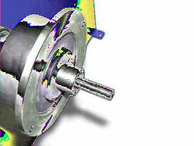
6 2. Technological description 2.1 PURPOSE C72/2 EVO C72SE/2 EVO is used to balance the wheels of cars, vans, 4-WD, motorcycles and scooters weighing less than 75 Kg. It can be operated in the temperature range of 0 to + 45 C The machine can operate only on fl at non resilient floor. To lift the machine, lever only on the base where the 3 support points are located. never, under any circustance, apply force to other points such as the spindle, head, or accessory shelf. It functions properly without having to fasten it to the floor with wheels weighing up to 35 kg; for heavier wheels, fasten it at the points indicated. Thanks to the new and exclusive VDD (Virtual Direct Drive) system, reliable unbalance measurements can be made in a short time, almost half the time of the cycle used with respect to other balancers in this range. The main features include: machine settings menu. optimisation of tyre and rim unbalance. static programme, ALUS; SPLIT; Unbalance optimization; Double operator; Self diagnostics; Self calibration. automatic minimisation of static unbalance wheel locking; gauge locking (only SE) automatic width (option) eccentricity measurement (option) 2.2 TECHNICAL SPECIFICATIONS The following data refers to the balancer in its standard configuration. Single-phase power supply 115 / 230 V 50/60 Hz Protection class IP 54 Max.power consumption 0,65 Kw Balancing speed 100 min -1 Cycle time for wheel 4.7 sec. (5 3/4 x14 ) 15 Kg. Max.resolution of measurement 1 gram Position resolution ± 1.4 Average noise < 70 db (A) Rim-machine distance mm Rim width setting range or mm Diameter setting range or mm Min/max. compressed air pressure 8 10 Kg/cm 2 approx. 0.8 to 1 Mpa; approx. 8 to 10 BAR; approx. 115 to 145 PSI. Air consumption for wheel lock/release 4 lt. (8 Kg./cm 2 ) 2.3 DIMENSIONS AND WEIGHTS CONTROL PANEL WEIGHT-TOOL HOLDER LOCK NUT AUTOMATIC GAUGE COLLAR (VERS. SE) BRAKE/BP PEDAL The machine weighs 130 kg. 6 Technological description
7 3. Starting WARNING BEFORE SWITCHING ON THE MACHINE, MAKE SURE THAT ALL THE CONNECTIONS DESCRIBED IN THE INSTALLATION CHAPTER HAVE BEEN MADE CORRECTLY. THE FOLLOWING OPERATIONS INVOLVE A POTENTIAL RISK FOR THE OPERATOR, GIVEN THE PRESENCE OF VOLTAGE ON THE EQUIPMENT. THE PERSONAL PROTECTIVE EQUIPMENT DESCRIBED IN THE INSTALLATION MANUAL MUST BE WORN AND WORK MUST BE DONE WITH DUE CARE AND ATTENTION. OPERATIONS MAY ONLY BE PERFORMED BY A SPECIALISED TECHNICIAN. Before powering the machine, carry out the following checks: 1. check that the balancing machine touches the floor at the three support points; 7. Firmly attach the wheel to the balancer shaft using the lock nut. In the pneumatic version, use the spe cific collar provided. For operation of the spindle with pneumatic locking (constant thrust air spring) connect the wheel balancer to the compressed air mains. The connection fitting is located at the back of the machine. At least 8 Kg/cm 2 (~ 0.8 MPa; ~ 8 BAR; ~ 115 PSI) pressure is needed for correct operation of the release device. 8. In the normal version, the pedal controls a mechani cal brake which facilitates locking the locking ring and positioning the wheel for correction. In the pneumatic version, it allows fastening/relea sing the wheel on the adapter using the collar. The pedal has two stable positions: upper position for unlocking; lower position for locking the wheel. 2. make sure that all the parts of the balancer are cor rectly connected and fixed; 3. make sure that the parameters (voltage and frequency) of the mains power supply are compatible with those indicated on the rating plate of the balancer; 4. make sure the power cable is correctly connected; 5. make sure the machine shaft and flange hole are clean. 9. The wheel is automatically locked when reaching the correct angular position for weight application on the inside and outside, turning it slowly by hand. To unlock the wheel, turn it hard to move it from the correct correction position. 10. To switch on the balancer press the switch on the left-hand side of the machine. CAUTION ANY TRACES OF DIRT MAY AFFECT BALANCING ACCURACY. 6. Position the wheel on the terminal with the inner part facing the balancer; Starting 7


8 SE2-Mounting 0m m B A 1-2 mm C D E F G SE2 MOUNTING
.")
.")
.")
9 SE2-Dismounting 360 A B C D Cone E - Quando possibile, centrare le ruote con cono dall'interno (vedi disegno). - Evitare di usare il manicotto RL con cerchi di ferro. - Whenever possible, centre the wheels with the cone from the inside (see the drawing). - Avoid using the RL sleeve with metal rims. - Lorsque c est possible, centrer les roues avec le cône de l intérieur (voir dessin). - Eviter d utiliser le manchon RL avec les jantes en fer. - Wenn möglich, die Räder mit Konus von Innen heraus zentrieren (siehe Zeichnung). - Bei Eisenfelgen die Verwendung der Muffe RL vermeiden. - Siempre que sea posible, centrar las ruedas con cono desde dentro (véase dibujo). - Evitar usar el manguito RL con llantas de hierro. - Quando possível, centre as rodas com cone pelo lado de dentro (ver fi gura). - Evite utilizar a luva RL com jantes de ferro. SE2 DISMOUNTING
10 4. Control panel Digital readouts, AMOUNT OF UNBALANCE, inside/outside 3-4 Digital readouts, POSITION OF UNBALANCE, inside/outside 5 Indicators, correction mode selected 6 Indicators, selection made 7 Push button, unbalance reading < 5 g (25 oz) 8 Push button, operator selection 9 Push button, selection of mode of correction 10 Push button, SPLIT (unbalance spread) 11 Push button, FUNCTIONS MENU 12 Push button, menu selection confi rmation 13 Push button, cycle start 14 Push button, emergency/home 15 Push button position repeater 16 Manual dimension setting buttons (only possible after specifi c activation) 17 Push button, unbalance optimization 18 Push button, eccentricity measurement (option) 19 Indicator, distance gauge position 20 Push button, grams/ounces selection 21 Push button, HOME (terminate function) CAUTION PRESS THE BUTTONS WITH YOUR FINGERS. NEVER USE THE COUNTERWEIGHT GRIPPERS OR OTHER POINTED OBJECTS! 10 Control panel
11 5 Use of the wheel balancer 5.1 PRESETTING OF WHEEL DIMENSIONS The balancing data is set by means of an intelligent automatic gauge; confi rmation of the measurement and the position appear on the display. The round part of the gauge must rest on the rim where the weight will be positioned. The correct measurement is that which can be measured with the compass gauge provided. b b) adhesive weights: make two successive measurements on two correction planes inside the rim. The balancing machine automatically interprets that the correction will be made with adhesive weights and the following appears: a For a different combination of the type or position of the weights on the rim, use the button. b AUTOMATIC WIDTH (OPTION) At the end of automatic distance and diameter measurement, if the LA sonar is present, the machine prepares for acquisition of this value: While the gauge is moving the following appears: when the measurement has been stored: a) standard weights: when only one measurement is made, the machine interprets the presence of a rim with clip-on weight correction The LT script on the LH matrix display indicates that LIGHT TRUCK wheel measurement is set (large dimension wheels such as off-road, trucks or wheels which protrude signifi cantly from the rim). This function can be enabled/disenabled by pressing push button. Slowly close the wheel guard until a The width value (b) must be set with the buttons. beep is heard. If AUTOMATIC START is enabled when the guard is closed, the balancing machine performs a cycle to measure the imbalance, otherwise the width value just acquired is shown. Use of the wheel balancer 11
12 Press the button to perform a spin Modifying set dimensions If the wheel dimensions have been entered incorrectly, the parameters can be modified without repeating the balancing spin by pressing for 2 seconds : For unbalance within tolerance 0 (zero); using values within tolerance can be viewed. If the static unbalance is greater than 30 g, the LED fl ashes to suggest an unbalance optimisation operation (see UNBALANCE OPTIMISATION). (select access parameter modifi cation to modify: (a) distance, (b) width, (d) diameter 5.3 EXACT POSITIONING OF THE ADHESIVE WEIGHT BY MEANS OF THE GAUGE WITH CLIPS In the case of standard weights: (a)distance,(b)width,(d)diameter In the case of adhesive weights: (a1) inside distance,(a2) outside distance,(d1) inside diameter,(d2) outside diameter Press if using the correction method with adhesive weights on the inside of the rim FI FE press to select (a) (b) or (d) to recalculate the unbalance or: pull out the gauge to repeat the measurement to obtain the new measurement. 5.2 MEASUREMENT RESULT Fit the correction weight in the specific gauge seat with the adhesive part facing upwards Bring the wheel into correct angular position for the plane to be corrected If the wheel clamp option is enabled (see MENU),the wheel is automatically clamped in the correction position. Pull out the gauge up to the distance set (see WHEEL DIMENSIONS PRESETTING b/c) If the buzzer is enabled (see MENU), the attainment of the weight application distance is accompanied by a beep. Using the special weight pusher, rotate the gauge until the correction weight adheres to the rim. If gauge locking is enabled (see MENU), the gauge is automatically locked when the weight application distance is reached. To release the gauge, lower it to below 10 diameter the fact that the weight application position is no longer vertical is automatically compensated. INDICATION The approach of the weights to the correction positions is indicated by the LEDs number 19 Inside Move the wheel manually until all the LED s corresponding to the side light up. The display shows the measured unbalance. If the wheel clamp option is enabled (see MENU), the wheel is automatically clamped in the correction position. Pressing the chuck can be locked/released in any position to facilitate mounting the wheel (see MENU). 12 Use of the wheel balancer
13 Use and maintenance manual Rev Outside 2 1 d. Move spoke 1 to the correction position as indicated by the position LED s 1 To cancel the function, press the close the guard and press the spin. 5.4 button again button to start a new SPLIT FUNCTION (unbalance resolution) The SPLIT function is used to position the adhesive weights behind the wheel spokes (angle > 18 ) so that they are no longer visible (for alloy rims). Use this function in the ALU or STATIC mode where the adhesive weight is applied to the outer side of the rim. Enter the wheel dimensions in the ALU S mode and press START. a. Turn the wheel to the outer side unbalance correction position To return to the normal unbalance indication press any button. INFORMATION The spoke-to-spoke distance must be a minimum of 18 and a maximum of 120 (if not, errors 24, 25 or 26 appear). Spokes with irregular or inconstant angles can be compensated b. Move one of the spokes to 12 o clock (e.g.: 1) and DOUBLE OPERATOR PROGRAM This program allows memorizing the dimensions of two types of wheels. Thus two operators can work simultaneously on two differents cars using the same balancing machine. The system memorizes two programs with various present dimensions. Press to select the operator (1 or 2). 2. Enter the dimensions (see WHEEL DIMENSIONS PRESETTING) press 3. Press 1 2 and to automatically store the program to the curren tly selected user. Press c. Following the direction of rotation indicated by the position LED s, move spoke 2 to12 o clock and press to carry out the balancing as usual to select program 1 or 2 for subsequent balancing operations without setting the dimensions again.. The value to use for correction in position 2 is displayed. Use of the wheel balancer 13
14 5.6 UNBALANCE OPTIMISATION This operation is performed to reduce the static unbalance of the wheel. It is suitable for static unbalance values in excess of 30 grams. 5.7 AUTOMATIC MINIMIZATION OF STATIC UNBALANCE Initial unbalance sx dx g g Phase shift 50 Possible approximations a. If no unbalance was measured before, START appears on the display. Press this button to proceed. b. Make a reference mark on the flange and the rim (using a piece of chalk, for example). With the aid of a tyre remover, turn the tyre on the rim by 180. Refi t the wheel in such a way that the reference marks on the rim and the fl ange coincide. Press START to begin reading. c. RH display: percentage reduction value LH display: actual static unbalance value which can be reduced by rotation sx dx sx dx g g g g g g g static residue static residue static residue static residue With traditional wheel balancer sx 4 g 3 g 1 g 6 g dx sx Choice with minimum static unbalance This program is designed to improve the quality of balancing without any mental effort or loss of time by the operator. In fact by using the normal commercially available weights, with pitch of 5 in every 5 g, and by applying the two counterweights which a conventional wheel balancer rounds to the nearest value, there could be a residual static unbalance of up to 4 g. The damage of such approximation is emphasized by the fact that static unbalance is cause of most of disturbances on the vehicle. This new function, resident in the machine, automatically indicates the optimum entity of the weights to be applied by approximating them in an intelligent way according to their position in order to minimize residual static unbalance. 5.8 ECCENTRICITY MEASUREMENT (OPTION) The much enlarged fi gures show the outer tyre surface and axis of wheel rotation. dx g A B d. Mark the two positions of the rim and tyre, and turn the tyre on the rim until the positions coincide to achieve the optimisation shown on the display TYRE POSITION RIM POSITION To cancel optimisation at any time, press. Fig. A - shows measurement of the total Peak-to-Peak eccentricity defi ned as maximum radial deviation of the tyre surface. Fig. B - shows measurement of the eccentricity of the 1st harmonic, i.e. the eccentricity of that circle which recopies the tyre shape, by averaging the local deviations of the tyre from the round shape. Obviously the P.P. measurement is normally greater than that of the 1st harmonic. Tyre manufacturers normally supply two different tolerances for the two eccentricities. The radial eccentricity measurements is automatically carried out after the unbalance measurement without having to go into particular procedures. Remember to position the sonar sensor in front of the surface to be measured before pressing the button. 14 Use of the wheel balancer
15 INDICATION The eccentricity measurement can be enabled/disenabled by a specific SETUP function (see MENU). Measurement results: Pressing the value of the fi rst harmonic with the relative phase is displayed. Hold down the value. button to display the Peak-Peak Release the button to return to the display of the fi rst harmonic value. Press to return to the measurement screen. INDICATION The eccentricity measurement is valid up to max. tyre Ø of 1000 mm. Use of the wheel balancer 15
16 6. Setup 6.1 MENU This is used to personalise some balancer functions and to perform calibrations. To access this section, press the FUNCTIONS MENU button. Eccentricity measurement on/off (option) diameter mm/inch width mm/inch start from guard closing approximates 1-5g oz on/off beep signal See AUTO-DIAGNOSTICS See SELF-CALIBRATION screen saver operating time in minutes (SE) Type of display of unbalance phase on/off wheel locking (SE) * * * Calibration of automatic RIM DISTANCE gauge Calibration of automatic DIAMETER gauge WIDTH calibration on/off gauge locking (SE) RETURN TO MEASUREMENT SCREEN INFORMATION * N.B. If such indications fail to appear, contact Technical Service. 16 Menu
17 Use and maintenance manual Rev Inside correction Self-diagnostics The machine can perform self-diagnostics to check the LED s on the control panel and make sure the encoder reads correctly. To perform this operation, view the SETUP menu. - Outside correction In the self-diagnostics sequence, all the LED s on the panel light up for a few seconds in order to check operation. When the LED s go out, the machine automatically moves on to the encoder reading phase. When the wheel is turned manually (forwards and backwards), the display shows its exact position. The value lies between 0 (zero) and 255. MEASURING RESULT OF SPLIT UNBALANCE: Each weight to be applied has its own display (1 for the inside and 2 for the outside in ALUS) Type of display of unbalance phase Unbalance inconsistent NOT in position The type of display of the unbalance phase can be selected, different from what is described in the manual to date. Display the SETUP menu: 1 2 Correction position 1 1. Press 2 to view the unbalance phase 1 display function Correction position 2 to modify the type of unbalance 2. Press phase display and confirm 1 2 In this case the unbalance phase is indicated in the following way: INFORMATION The standard type of display is type 1, i.e. that described throughout the manual. Menu 17
18 6.1.3 Calibration To calibrate the machine, proceed as follows: Fit an average size wheel with a metal rim on the shaft. Example: 6 x 15 (± 1 ). Set the wheel measurements as described in paragraph USE OF THE WHEEL BALANCER. 6.2 AUTOMATIC GAUGES CALIBRATION Rim distance gauge Display the SETUP menu 1. Press to view the rim distance gauge CALIBRATION function. CAUTION SETTING INCORRECT DIMENSIONS WOULD MEAN THAT THE MACHINE IS NOT CORRECTLY CALIBRATED, THEREFORE, ALL SUBSEQUENT MEASUREMENTS WILL BE INCORRECT UNTIL CALIBRATION IS PER- FORMED ONCE AGAIN WITH THE CORRECT DIMENSIONS. 2. Leave the distance gauge in rest position and press Display the SETUP menu: 3. Bring the gauge in line with the adapter flange and press 1. Press to view the CALIBRATION function. CORRECT CALIBRATION Return the gauge to rest position. The wheel balancer is ready for operation. 2. Add a standard weight of 60 g (2.00 oz) to the outer side, in any position.. 3. Shift the standard weight from the outside to the inside keeping the same position. 4. Turn the wheel until the standard weight is at the top (12 o clock). INDICATION In the event of errors or faulty operation, the writing r.p. : appears on the display : shift the gauge to the rest position and repeat the calibration operation exactly as described above. If the error persists, contact the Technical Service Department. In the event of incorrect input in the rim distance gauge calibration function, press Diameter gaugee Display the SETUP menu to cancel it. 5. End of calibration. 1. Press to view the diameter gauge CALIBRATION function. m 2. Place the round part of the gauge terminal on the To cancel calibration at any time, press. flange as shown in the figure and press 18 Menu


 Display the SETUP menu 1.")
19 3. The number 353 ± 3 appears on the left display. A = Distance: Gauge at rest to 0 sonar In the event of incorrect input in the width gauge calibration 4. Turn the gauge downward position the round part of the gauge terminal at 40 mm (radial distance) from the flange as indicated in the figure; alternati vely use one of the cones provided as shown in the images function, press to cancel it. 40 mm 5. The number 254 ± 3 should appear on the left display. The calibration is already correct. If not, press the button holding the gauge still at 40 mm: the number 254 appears on the left display. Return the gauge to rest position Width sonar (option) Display the SETUP menu 1. Press to view the width sonar CALIBRATION function. 2. Set with the distance in mm betwe en the Sonar sensor (0 sonar) and the end of the distance gauge (at rest). Menu 19
20 7. Diagnostics 7.1 INCONSISTENT UNBALANCE READINGS In some cases, when a wheel that has just been balanced is repositioned on the balancer, the machine can detect an unbalance. This is not a machine problem but is due to faulty mounting of the wheel on the flange. In other words, when mounting the wheel after initial balancing, it has taken another position with respect to the balancer shaft axis. If the wheel has been mounted on the flange with screws, the screws may not have been tightened correctly (crisscross sequence) or the tolerances of the holes drilled in the wheel may be too large. Small errors, up to 10 grams (0.4 oz), are to be considered normal in wheels locked with the relative cone: The error is normally greater for wheels locked with screws or studs. If, after balancing, the wheel is still unbalanced when refitted on the vehicle, this could be due to an unbalanced brake drum or, very often, the tolerances of the holes drilled in the rim and drum are too large. In this case, balancing should be performed using a balancer with the wheel mounted on the vehicle. 7.2 ALARM SIGNAL The machine has a self-diagnostics cycle which identifies the most frequent malfunctions during the normal work cycle. These malfunctions are processed by the system and shown on the display. 20 Diagnostics
21 WARNING THE INFORMATION IN THE POSSIBLE REMEDY COLUMN REQUIRES WORK TO BE PERFORMED BY SPECIALIST TECHNICIANS OR OTHER AUTHOR- ISED PEOPLE WHO MUST ALWAYS WORK USING THE PERSONAL PROTECTIVE EQUIPMENT INDICATED IN THE INSTALLATION MANUAL. IN SOME CASES, THIS WORK CAN BE PERFORMED BY A NORMAL OPERATOR. ERROR CAUSE POSSIBLE REMEDY Black The wheel balancer does not switch on. 1. Check the machine is properly connected to the mains power supply. 2. Check the fuses on the power board and replace if necessary. 3. Replace the CPU board. Err. 1 No rotation signal. 1. Use the self-diagnostics function to check the encoder. 2. Replace the encoder. 3. Replace the CPU board. Err. 2 Speed too low during detection. During the unbalance measurement revolutions, the wheel speed has fallen to below 42 rpm. 1. Make sure that a vehicle wheel is mounted on the wheel balancer. 2. Use the self-diagnostics function to check the encoder. 3. Disconnect the piezo connectors from the board and do a spin (if no error is detected, replace the piezo sensors). 4. Replace the CPU board. Err. 3 Unbalance too high. 1. Check the wheel dimensions setting. 2. Check the detection unit connections. 3. Run the machine calibration function. 4. Mount a wheel with more or less known unbalance (less than 100 grams) and check the response of the machine. 5. Replace the CPU board. Err. 4 Rotation in opposite direction. 1. Use the self-diagnostics function to check the encoder. 2. Check the encoder bearing/spring. Err. 5 Err. 7 Err. 8 Err. 9 Guard open The [START] pushbutton was pressed without fi rst closing the guard. NOVRAM parameter read error 1. Reset the error. 2. Close the guard. 3. Verify the function of the protection switch. 4. Press the [START] button. 1. Switch off the machine and wait for at least ~ 1 min; re-start the machine and check it works properly. 2. Repeat machine calibration. 3. Replace the CPU board. Err. 11 Too high speed error. The average spinning speed is more than 240 rpm. 1. Check functioning of the phase encoder and, in particular, the reset signal. 2. Replace the computer board. Err. 12 Unbalance measuring cycle error. 1. Verify phase pick-up board function. 2. Verify correct motor operation. 3. Replace the computer board. Err.14 Err.15 Err.16 Err.17 Err.18 Err. 19 Err. 20 Unbalance measurement error. Wheel still. The wheel must remain still for more than one second after START Use the self-diagnostics function to check the encoder. Check the detection unit connections. Check the machine earthing connection. Mount a wheel with more or less known unbalance (less than 100 grams) and check the response of the machine. Replace the CPU board. Use the self-diagnostics function to check the encoder. Check the connections on the power board. Replace the CPU board. Err. 21 Motor on for more than 15 seconds. 1. Use the self-diagnostics function to check the encoder. 2. Check the connections on the power board. 3. Replace the CPU board. Diagnostics 21
22 Err. 22 Err. 24 Maximum number of spins possible for the unbalance measurement has been exceeded. Distance between the spokes less than 18 degrees. 1. Check that a vehicle wheel has been mounted on the wheel balancer. 2. Check functioning of the phase encoder and, in particular, the reset signal. 3. Replace the computer board. 1. The minimum distance between the spokes where the unbalance is to be split must be greater than 18 degrees. 2. Repeat the SPLIT function increasing the distance between the spokes. Err. 25 Distance between the spokes greater than 120 degrees. 1. The maximum distance between the spokes where the unbalance is to be split must be less than 120 degrees. 2. Repeat the split function increasing the distance between the spokes. Err. 26 First spoke too far from the unbalance 1. The maximum distance between the unbalance position and the spoke must be less than 120 degrees. 2. Repeat the split function increasing the distance between the spokes and the unbalance. Err. 55 Err. 56 Sonar readout error. Sonar values are insuffi cient for correct measurement of eccentricity. Lateral Sonar readout error. Lateral Sonar value readout impossible. 1. Position the eccentricity measurement sonar correctly before performing the measurement. 2. Make sure that the wheel does not halt before completing at least 4/5 revolutions after the fi rst braking impulse. 3. Mount a wheel of medium dimensions (14 x5 ¾ ) and perform an eccentricity measurement. If in these conditions error 55 no longer occurs, this means that the wheel inertia causing the problem is such as to half the wheel before having acquired the minimum number of values necessary for reliable eccentricity measurement. 1. Position the eccentricity measurement lateral sonar correctly before performing the measurement. 2. Check eccentricity lateral sonar connections. 3. Check the power supplies on the power board. 4. Replace the eccentricity lateral sonar. 5. Make sure that the wheel does not stop before completing at least 4/5 revolutions after the fi rst braking impulse. 6. Replace the computer board. 22
23 8. Maintenance 8.1 GENERAL CAUTION BEFORE PERFORMING ANY MAINTENANCE OPERATIONS, MAKE SURE THE MACHINE HAS BEEN DISCONNECTED FROM THE MAINS POWER SUPPLY. ALWAYS USE THE PERSONAL PROTECTIVE EQUIPMENT INDICATED IN THE INSTALLATION MANUAL Introductory notes This machine has been designed so as not to require routine maintenance, apart from accurate periodic cleaning. It is important to keep the machine perfectly clean in order to prevent dust or impurities from compromising the operation of the balancer. WARNING THE PEOPLE RESPONSIBLE FOR CLEANING THE AREA WHERE THE MACHINE IS INSTALLED MUST WEAR PERSONAL PROTECTIVE EQUIPMENT IN ORDER TO WORK IN SAFETY AND ACCORDING TO THE CURRENT OCCUPATIONAL HEATH AND SAFETY REGULATIONS. Specialist staff must be authorised and especially trained concerning the dangers that may arise during operation and the correct methods for avoiding them. They must always work with great care and pay full attention. If, exceptionally, the staff removes the guards to carry out a particular specialist technical maintenance, inspection or repair job, they are required to put them back after work. After work, staff must make sure that foreign objects, in particular mechanical pieces, tools or devices used during the operative procedure that could cause damage or malfunctions are not left inside the balancer. For safety, before starting work, maintenance, inspection and repair staff must disconnect all power sources and take all the necessary preventive safety measures. As well as operating frequencies, the operations described below indicate the qualifications that staff must possess in order to perform the operation Replacing fuses Some protection fuses are located on the power board (see wiring diagrams) accessible by dismantling the weight shelf). If fuses require replacement, use ones with an identical current intensity. As extraordinary maintenance must be performed by service staff or, in any case, by specifically authorised and trained people, is not dealt with in this manual Safety rules Performing specialist activities on the equipment, particularly if the guards need to be dismounted, exposes people to serious danger due to the presence of potentially live parts. The rules shown below must be scrupulously followed. People must always use the Personal Protective Equipment indicated in the Installation Manual. During activities, unauthorised people may not access the equipment and WORK IN PROGRESS signs will be erected in the department in such a way that they are visible from every place of access. Maintenance 23

24 9. Disposal 10. Spare parts 10.1 IDENTIFICATION AND ORDERING METHOD CAUTION THE INSTRUCTIONS IN THIS CHAPTER ARE INDICATIVE. REFER TO THE REGULATIONS IN FORCE IN THE COUNTRY WHERE THE EQUIP- MENT IS USED. 9.1 DISPOSING OF THE BALANCER The balancer must be disposed of after dismounting the various parts. For disposal operations, as well as wearing the Personal Protective Equipment indicated in the INSTALLATION MANUAL, refer to the instructions and diagrams in this manual. If necessary, request specific information from the manufacturer. After dismounting the various parts, sort the various components, separating metal from plastic, from copper, etc., according to the sorted waste disposal regulations in force in the country in which the equipment is dismantled. If the various components must be stored before being taken to the dump, make sure to keep them in a safe place protected from atmospheric agents in order to prevent them from contaminating the ground and the water table. 9.2 DISPOSING OF ELECTRONICS COMPONENTS Community directive 2002/96/EC, assimilated in Italy with legislative decree n 151 of 25th July 2005, requires electrical and electronic equipment manufacturers and users to comply with a number of obligations concerning the collection, treatment, recovery and disposal of this waste. The various parts can be identified using the drawings and diagrams in the machine technical file which is archived by the Manufacturer to which a request can be made. For off-the-shelf parts, the technical manuals or the supplier's original documents can be provided if the Manufacturer deems this to be useful. If not supplied, this documentation is also included in the machine Technical File, archived by the Manufacturer, as regards by Ministerial Decree 98/37/EC. In this case, contact the Technical Service to identify the required piece. If the required pieces are not in any position or they cannot be identified, contact the Technical Service, specifying the type of machine, its serial number and year of construction. This information is indicated on the machine identification plate. 11. Attached documentation If not supplied, this documentation is included in the Technical File of the machine, archived by the Manufacturer. In this case, contact the Technical Service for detailed information concerning the machine. Please scrupulously comply with these waste disposal regulations. Remember that abusive dumping of this waste leads to the application of the administrative penalties established by current law. 24 Disposal Spare parts Attached documents
1. FOREWORD 3 2. MACHINE DESCRIPTION PURPOSE TECHNICAL SPECIFICATIONS DIMENSIONS 6 3. STARTING 7 4.
 GB Use and maintenance manual General Index 1. FOREWORD 3 1.1 GENERAL 3 1.2 PURPOSE OF THE MANUAL 3 1.3 WHERE AND HOW TO KEEP THE MANUAL 3 1.4 MANUAL UPGRADES 3 1.5 COLLABORATION WITH USERS 3 1.6 MANUFACTURER
1. FOREWORD 3 2. MACHINE DESCRIPTION PURPOSE TECHNICAL SPECIFICATIONS DIMENSIONS AND WEIGHTS 6 3. STARTING 7 4.
 GB Use and maintenance manual General Index 1. FOREWORD 3 1.1 GENERAL 3 1.2 PURPOSE OF THE MANUAL 3 1.3 WHERE AND HOW TO KEEP THE MANUAL 3 1.4 MANUAL UPGRADES 3 1.5 COLLABORATION WITH USERS 4 1.6 MANUFACTURER
1. FOREWORD 3 2. MACHINE DESCRIPTION PURPOSE TECHNICAL SPECIFICATIONS DIMENSIONS 6 3. STARTING 7 4.
 EN Use and maintenance manual General Index 1. FOREWORD 3 1.1 GENERAL 3 1.2 PURPOSE OF THE MANUAL 3 1.3 WHERE AND HOW TO KEEP THE MANUAL 3 1.4 MANUAL UPGRADES 3 1.5 COLLABORATION WITH USERS 4 1.6 MANUFACTURER
Wheel Products. WP8300 Operators Manual Rev: 910
 Wheel Products by WP8300 Operators Manual Rev: 910 Table of Contents Warranty Page 1 1. General Page 2 General Safety Regulations Page 2 Field of Application Page 2 Overall Dimensions Page 2 Technical
1. FOREWORD 3 2. MACHINE DESCRIPTION PURPOSE TECHNICAL SPECIFICATIONS DIMENSIONS AND WEIGHTS 6 3. STARTING 7 4.
 GB Use and maintenance manual General Index 1. FOREWORD 3 1.1 GENERAL 3 1.2 PURPOSE OF THE MANUAL 3 1.3 WHERE AND HOW TO KEEP THE MANUAL 3 1.4 MANUAL UPGRADES 3 1.5 COLLABORATION WITH USERS 4 1.6 MANUFACTURER
Instructions for use CONTENTS
 Instructions for use I CONTENTS 1 - GENERAL 3 1.1 - GENERAL SAFETY REGULATIONS 3 1.1.1 - STANDARD SAFETY DEVICES 3 1.2 - FIELD OF APPLICATION 3 1.3 - OVERALL DIMENSIONS (standard guard) 3 1.4 - TECHNICAL
TABLE OF CONTENTS 1 - GENERAL...3
 Instructions for use I TABLE OF CONTENTS Page 1 - GENERAL...3 1.1 - GENERAL SAFETY REGULATIONS...3 1.1.1 - STANDARD SAFETY DEVICES...3 1.2 - FIELD OF APPLICATION...3 1.3 - OVERALL DIMENSIONS...3 1.4- TECHNICAL
2 - HANDLING, HOISTING START-UP...5
 Instructions for use I Contents Page 1 - GENERAL...3 1.1 - GENERAL SAFETY REGULATIONS...3 1.1.1 - STANDARD SAFETY DEVICES...3 1.2 - FIELD OF APPLICATION...3 1.3 - OVERALL DIMENSIONS...3 1.4- SPECIFICATION...4
2 - HANDLING, HOISTING START-UP...5
 Instructions for use I Contents Page 1 - GENERAL...3 1.1 - GENERAL SAFETY REGULATIONS...3 1.1.1 - STANDARD SAFETY DEVICES...3 1.2 - FIELD OF APPLICATION...3 1.3 - OVERALL DIMENSIONS...3 1.4- SPECIFICATION...4
2 - HANDLING AND HOISTING START-UP...5
 Instructions for use I INDEX page 1 - GENERAL... 3 1.1 - GENERAL SAFETY REGULATIONS...3 1.1.1 - STANDARD SAFETY DEVICES...3 1.2 - FIELD OF APPLICATION...3 1.3 - OVERALL DIMENSIONS...3 1.4 - TECHNICAL DATA...4
6275HS Wheel Balancer
 6275HS Wheel Balancer Installation Instructions Operating Instructions Safety Instructions Maintenance Instructions READ these instructions before placing unit in service KEEP these and other materials
2 - HANDLING, HOISTING START-UP...4
 Instructions for use I INDEX Page 1 - GENERAL...3 1.1 - GENERAL SAFETY REGULATIONS...3 1.1.1 - STANDARD SAFETY DEVICES...3 1.2 - FIELD OF APPLICATION...3 1.3 - OVERALL DIMENSIONS (standard protection)...3
1. FOREWORD 3 2. TECHNOLOGICAL DESCRIPTION PURPOSE TECHNICAL SPECIFICATIONS DIMENSIONS AND WEIGHTS 6 3.
 GB Use and maintenance manual General Index 1. FOREWORD 3 1.1 GENERAL 3 1.2 PURPOSE OF THE MANUAL 3 1.3 WHERE AND HOW TO KEEP THE MANUAL 3 1.4 MANUAL UPGRADES 3 1.5 COLLABORATION WITH USERS 4 1.6 MANUFACTURER
2 - HANDLING AND HOISTING COMMISSIONING...5
 Contents Instructions for use Page I 1- GENERAL...3 1.1 - GENERAL SAFETY RECOMMENDATIONS...3 1.1.1 - STANDARD SAFETY DEVICES...3 1.2 - FIELD OF APPLICATION...3 1.3 - OVERALL DIMENSIONS...3 1.4 - SPECIFICATION...4
PWB 50 Use and maintenance instruction manual
 PWB 50 Use and maintenance instruction manual English PWB50 INDEX Introduction 5 1.0 Foreword 6 1.1 General 6 1.2 Manual pourpose 6 1.3 Where And How To Keep The Manual 7 1.4 Manual Upgrades 7 1.5 Collaboration
Model 1650 Vibration Control Diagnostic System
 Model 1650 Vibration Control Diagnostic System Operating instructions I Index Page 1- GENERAL...3 1.1 - GENERAL SAFETY RECOMMENDATIONS...3 1.1.1 - STANDARD SAFETY DEVICES...3 1.2 - FIELD OF APPLICATION...3
User's manual Manual por el usuario
 ESPAÑOL FRANÇAIS ITALIANO EN ES User's manual Manual por el usuario ER75TD PORTUGUÊS ESPAÑOL DEUTSCH CEMB S.p.A. Via Risorgimento, 9 23826 Mandello del Lario (LC) ITALY Telefono: + 39 0341 706369 Fax:
Equilibreuses de roues
 Equilibreuses de roues 3607 NOTICE D UTILISATION Notice réf. G-NOT-3607C4 Indice : 0 Instructions for use I TABLE OF CONTENTS Page 1 - GENERAL...3 1.1 - GENERAL SAFETY REGULATIONS...3 1.1.1 - STANDARD
Models CB6 Series (CB66-VE)
") Models CB6 Series (CB66-VE) 1. CONTROL PANEL The machine control panel is shown in Figure F1. The control panel allows the operator to give commands and enter or modify data. The same control panel displays
Models CB6 Series (CB66-VE) 1. CONTROL PANEL The machine control panel is shown in Figure F1. The control panel allows the operator to give commands and enter or modify data. The same control panel displays
INSTALLATION, OPERATION AND MAINTENANCE MANUAL
 TW F - 150 Wheel balancing machine INSTALLATION, OPERATION AND MAINTENANCE MANUAL Read this entire manual carefully before installation or operation of the TW F-150. Follow the instructions strictly. 1
Mod: KLD6-12/35XLAS-N
 12/2011 Mod: KLD6-12/35XLAS-N Production code: 1914070 INSTRUCTION MANUAL LOGIC LINE PLUS HOOD Reseller Stamp for Warranty Dear customer, Above all, thank you for choosing our product and we would like
WHEEL BALANCER INSTRUCTION MANUAL DWC ATTENTION
 WHEEL BALANCER INSTRUCTION MANUAL DWC ATTENTION This manual is an integral part of the product. The warnings and instructions in this manual provide important information about SAFETY IN USE and MAINTENANCE
WHEEL BALANCER WITH MICROPROCESSOR FOR CARS, LIGHT COMMERCIAL VEHICLES AND MOTORCYCLES ( Series A )
") 0052-1 HofmannIndustrial GmbH A - 5302 Henndorf Hauptstraße 59 Tel +43-6214-6466-12 \ Fax -20 WHEEL BALANCER WITH MICROPROCESSOR FOR CARS, LIGHT COMMERCIAL VEHICLES AND MOTORCYCLES ( Series A ) Nr. 0052-1998.10
0052-1 HofmannIndustrial GmbH A - 5302 Henndorf Hauptstraße 59 Tel +43-6214-6466-12 \ Fax -20 WHEEL BALANCER WITH MICROPROCESSOR FOR CARS, LIGHT COMMERCIAL VEHICLES AND MOTORCYCLES ( Series A ) Nr. 0052-1998.10
Model 1850 Wheel Balancer
 Model 1850 Wheel Balancer Instructions for use I INDEX page 1 - GENERAL...3 1.1 - GENERAL SAFETY REGULATIONS...3 1.1.1 - STANDARD SAFETY DEVICES...3 1.2 - FIELD OF APPLICATION...3 1.3 - OVERALL DIMENSIONS...3
 VOLUME 2.0 2 This page intentionally left blank JWB 100 Operator s Manual page 3 Table of Contents 1 Summary 1.1 Features 4 1.2 Specifications 4 2 Installation 2.1 Installation 5 3 Structure 3.1 Main Structure
INSTALLATION, OPERATION, MAINTENANCE MANUAL KEEP THE MANUAL NEAR THE MACHINE ALL TIME AND MAKE SURE ALL USERS HAVE READ THIS WHEEL BALANCER
 INSTALLATION, OPERATION, MAINTENANCE MANUAL KEEP THE MANUAL NEAR THE MACHINE ALL TIME AND MAKE SURE ALL USERS HAVE READ THIS WHEEL BALANCER FOLLOW THE INSTRUCTIONS CAREFULLY TO GRANT THE MACHINE A CORRECT
NOTE: THESE PROCEDURES ARE THE SAME AS BEING IN THE SERVICE MODE. NOTE: ONCE THE UNIT IS POWERED DOWN THE VALUES FOR C4 WILL BE GONE.
 SERVICE CODES There are only two service codes that are accessible in a Users Mode. These are C4 (Unbalance Compensation) and C12 (Display Counter Indication). To access these service code in Users Mode
Instructions for use I 0375 GB - 1
 Instructions for use I INDEX pae 1 - GENERAL...3 1.1 - GENERAL SAFETY REGULATIONS...3 1.1.1 - STANDARD SAFETY DEVICES...3 1.2 - FIELD OF APPLICATION...3 1.3 - OVERALL DIMENSIONS...3 1.4 - TECHNICAL DATA...4
ECONOMISER SERIES E2T USER MANUAL
 TURBO S.R.L. Electronic Control Systems for Dust Collectors e-mail: info@turbocontrols.it web: www.turbocontrols.it TEL. ++39 (0)362 574024 FAX ++39 (0)362 574092 ECONOMISER SERIES E2T USER MANUAL 24/06/2014
2 - HANDLING AND HOISTING COMMISSIONING...5
 Instructions for use I CONTENTS pae 1 - GENERAL...3 1.1 - GENERAL SAFETY REGULATIONS...3 1.1.1 - STANDARD SAFETY DEVICES...3 1.2 - FIELD OF USE...3 1.3 - OVERALL DIMENSIONS...3 1.4 - SPECIFICATION...4
Wheel Balancer Manual(A)
") Wheel Balancer Manual(A) Contents 1.General ----------------------------------------------------------------------------------------------------------------------------------2 2.Machine assembly------------------------------------------------------------------------------------------------------------------------2
Wheel Balancer Manual(A) Contents 1.General ----------------------------------------------------------------------------------------------------------------------------------2 2.Machine assembly------------------------------------------------------------------------------------------------------------------------2
1. GENERAL INFORMATION
 Instructions for use I Index 1. GENERAL INFORMATION 3 1.1 - GENERAL SAFETY RECOMMENDATIONS 3 1.2 - FIELDS OF APPLICATION 4 1.3 - OVERALL DIMENSIONS 4 1.4 - TECHNICAL DATA 5 2. MOVING THE CABINET 5 3. POWER
WHEEL BALANCERS & TYRE CHANGERS QUALITY YOU EXPECT AT A PRICE YOU WOULDN T THE STANDARD IN INFORMATION, EQUIPMENT AND DIAGNOSTICS SYSTEMS
 QUALITY YOU EXPECT AT A PRICE YOU WOULDN T THE STANDARD IN INFORMATION, EQUIPMENT AND DIAGNOSTICS SYSTEMS http://diagnostics.snapon.co.uk INTRODUCTION TYRE AND WHEEL BROCHURE The Sun range of Tyre Changers
Armon Edero. User manual
 User manual Armon Edero Foreword.... 2 Symbols used 2 Intended use.... 2 About the Armon Edero... 2 Mounting options of the Edero 2 Braces. 3 How to set up the Armon Edero.. 3 How to attach the brace to
HST -LS Interlocking device (Translation of Original Manual)
") Installation and Operating Manual for Components HST -LS Interlocking device (Translation of Original Manual) HST-LS Ident.-No.: 10268 HST-LS Ident.-No.: 10269 HST-LS, pictured Ident-Nr. 10269 The image
Installation and Operating Manual for Components HST -LS Interlocking device (Translation of Original Manual) HST-LS Ident.-No.: 10268 HST-LS Ident.-No.: 10269 HST-LS, pictured Ident-Nr. 10269 The image
CO 3-WAY PNEUMATIC VALVE INSTRUCTION MANUAL 2080
 CO 3-WAY PNEUMATIC VALVE INSTRUCTION MANUAL 2080 STI S.r.l has taken every care in collecting and verifying the documentation contained in this Instruction Manual. The information herein contained are
Operating instructions
 Operating instructions Digital tank contents indicator DTA 10 DTA 10 DTA 10 0 4.0 m fuel oil 0 3.5 m water Read instructions before using device! Observe all safety information! Keep instructions for future
USE AND INSTALLATION HANDBOOK
 Date : 10/02/14 Rev. 01 PR.T : FG006172 USE AND INSTALLATION HANDBOOK DUPLEX-UP CONTROL PANEL FOR 2 ELECTRIC PUMPS WITH CURRENT CONTROL. DUPLEX-UP Via Enrico Fermi 8-35020 Polverara PD Tel.049/9772407
775/875 Wheel Balancer
 775/875 Wheel Balancer See Balancing Your First Tire on page 1. Installation Instructions Operating Instructions Safety Instructions Maintenance Instructions READ these instructions before placing unit
Instruction of connection and programming of the VECTOR controller
 Instruction of connection and programming of the VECTOR controller 1. Connection of wiring 1.1.VECTOR Connection diagram Fig. 1 VECTOR Diagram of connection to the vehicle wiring. 1.2.Connection of wiring
Relay Retrofit Program Cutting Tool Safety Guide
 Relay Retrofit Program Cutting Tool Safety Guide Copyright This document and parts thereof must not be reproduced or copied without written permission from ABB, and the contents thereof must not be imparted
NTB-550 Manual. Contents
 1 NTB-550 Manual Please read this Manual before using the Machine. You will need to know the safety instructions, System Settings, Wheel Parameters Input and Calibration process before you can properly
Instruction Manual PC104/PC105 3-PHASE SOCKET TESTER. Check out what else you can get from Martindale:
 Check out what else you can get from Martindale: 17th Edition Testers Accessories Calibration Equipment Continuity Testers Electricians Kits Environmental Products Full Calibration & Repair Service Fuse
K&L MC200 ELITE WHEEL BALANCER Product Manual - MC Wheel Balancing
 Product Manual - MC Wheel Balancing Thank you for purchasing this K&L Product. Please inspect this unit for damage prior to use. This manual will review balancing a motorcycle wheel. Please read the entire
SI AT A22. English. Printed: Doc-Nr: PUB / / 000 / 01
 SI AT A22 English 1 Information about the documentation 1.1 About this documentation Read this documentation before initial operation or use. This is a prerequisite for safe, trouble-free handling and
Atlas ESR and ESR + Equivalent Series Resistance and Capacitance Meter. Model ESR60/ESR70. Designed and manufactured with pride in the UK.
 GB60/70-9 Atlas ESR and ESR + Equivalent Series Resistance and Capacitance Meter Model ESR60/ESR70 Designed and manufactured with pride in the UK User Guide Peak Electronic Design Limited 2004/2016 In
Operating Instructions Precision balance
 KERN & Sohn GmbH Ziegelei 1 D-72336 Balingen E-Mail: info@kern-sohn.com Tel: +49-[0]7433-9933-0 Fax: +49-[0]7433-9933-149 Internet: www.kern-sohn.com Operating Instructions Precision balance KERN Version
Safety Shock Absorbers SCS33 to SCS64
 Safety Shock Absorbers SCS33 to SCS64 1 Operating Instruction SCS33-25EU SCS33-50EU SCS45-25EU SCS45-50EU SCS45-75EU Rod Button SCS64-50EU SCS64-100EU SCS64-150EU Integrated Rod Seals Main Bearing Content
2 - HANDLING, HOISTING START-UP...5
 Instructions for use I Contents Page 1 - GENERAL...3 1.1 - GENERAL SAFETY REGULATIONS...3 1.1.1 - STANDARD SAFETY DEVICES...3 1.2 - FIELD OF APPLICATION...3 1.3 - OVERALL DIMENSIONS...3 1.4- SPECIFICATION...4
These operating instructions apply for: NCX 380 NCZ 300 NCX 480 NCZ 370 NCX 580 L NCZ 480 NCX 660 K NCZ 560 NCZ 660 NCZ 800
 Original instructions Operating Instructions for May 2010 Electric Internal Vibrators BA No. 1092E Series NCX and NCZ These operating instructions apply for: NCX 380 NCZ 300 NCX 480 NCZ 370 NCX 580 L NCZ
1175 Wheel Balancer. Installation Instructions Operating Instructions Safety Instructions Maintenance Instructions
 1175 Wheel Balancer See Balancing Your First Tire on page 1. Installation Instructions Operating Instructions Safety Instructions Maintenance Instructions READ these instructions before placing unit in
SI AT A22. English. Printed: Doc-Nr: PUB / / 000 / 03
 SI AT A22 English 1 Information about the documentation 1.1 About this documentation Read this documentation before initial operation or use. This is a prerequisite for safe, trouble-free handling and
Instruction manual. RP800 - HYDRAULIC actuator, load 150Kg. RP815 - LINAK actuator, load 150Kg
 HYDRAULIC patient lift RP800 - HYDRAULIC actuator, load 150Kg MA RP800_805_806_ 807_810_811_815 02 A_12-2010 Electric patient lifts RP805 - LINAK actuator, load 150Kg RP806 - HIWIN actuator, load 150Kg
NTB-800 Manual. Contents
 NTB-800 Manual Please read this Manual before using the Machine. You will need to know the safety instructions, System Settings, Wheel Parameters Input and Calibration process before you can properly balance
Atlas ESR. User Guide. Capacitance and Equivalent Series Resistance Meter. Model ESR60 (Enhanced)
") Atlas ESR Capacitance and Equivalent Series Resistance Meter Model ESR60 (Enhanced) User Guide Peak Electronic Design Limited 2004/2008 In the interests of development, information in this guide is subject
Atlas ESR Capacitance and Equivalent Series Resistance Meter Model ESR60 (Enhanced) User Guide Peak Electronic Design Limited 2004/2008 In the interests of development, information in this guide is subject
BoWex FLE-PA. BoWex FLE-PAC. KTR-N Sheet: Edition: EN 1 of BoWex FLE-PA / FLE-PAC Operating/Assembly instructions
 1 of 17 is a torsionally rigid flange coupling. It is able to compensate for shaft misalignment, for example caused by manufacturing inaccuracies, thermal expansion, etc. BoWex FLE-PA BoWex FLE-PAC Drawn:
Wilo-Control SC-Fire Jockey
 Pioneering for You Wilo-Control SC-Fire Jockey de en fr Einbau- und Betriebsanleitung Installation and operating instructions Notice de montage et de mise en service nl Inbouw- en bedieningsvoorschriften
3. Operating instructions: Minor 200
 1. Technical specifications 3. Operating instructions: Minor 200 Copyright 2015 by Endecotts Ltd. 13 1. Setting up Technical specifications SIEVE SHAKER MODEL: Minor 200 General Information The Minor 200
Repair Manual. General Pump is a member of the Interpump Group. Ref Rev.A 09-13
 Repair Manual General Pump is a member of the Interpump Group 8 INDEX 1. INTRODUCTION..................................................Page 3 2. REPAIR GUIDELINES..............................................Page
Sheet n 1 of 20 Doc. n WDMM/02/E MOD. WDMM INSTALLATION, USE AND SERVICE MANUAL. PETROL INSTRUMENTS S.r.l APRILIA (LT) - ITALY
 - ITALY") Sheet n 1 of 20 WATER DRAW/ MASTER METER PETROL COUNTER MOD. WDMM INSTALLATION, USE AND SERVICE MANUAL PETROL INSTRUMENTS S.r.l. - 04011 APRILIA (LT) - ITALY Sheet n 2 of 20 INSTALLATION, USE AND SERVICE
Sheet n 1 of 20 WATER DRAW/ MASTER METER PETROL COUNTER MOD. WDMM INSTALLATION, USE AND SERVICE MANUAL PETROL INSTRUMENTS S.r.l. - 04011 APRILIA (LT) - ITALY Sheet n 2 of 20 INSTALLATION, USE AND SERVICE
Valor 1000W Series Instruction Manual. Serie Valor 1000W Manual de Instrucciones. Série Valor 1000W Guide de I utilisateur
 Valor 1000W Series Instruction Manual Serie Valor 1000W Manual de Instrucciones Série Valor 1000W Guide de I utilisateur Serie Valor 1000W Bedienungsanleitung Serie Valor 1000W Manuale d instruzioni OHAUS
EC MACHINE DIRECTIVE COMPLIANCE DECLARATION
 EC MACHINE DIRECTIVE COMPLIANCE DECLARATION (DIRECTIVE 89/392 EEC, APPENDIX II, PART B) Manufacturer: FAAC S.p.A. Address: Via Benini, 1 40069 - Zola Predosa BOLOGNA - ITALY Hereby declares that: the 770
ProRide Diagnostic ProRide Diagnostic PL Wheel Balancer Models
 ProRide Diagnostic ProRide Diagnostic PL Wheel Balancer Models See Balancing Your First Tire on page 5. Safety Instructions Set-up Instructions Operation Instructions Maintenance Instructions READ these
230V DIESEL FUEL TRANSFER PUMP MODEL NO: DFT230
 230V DIESEL FUEL TRANSFER PUMP MODEL NO: DFT230 PART NO: 7160050 OPERATION & MAINTENANCE INSTRUCTIONS GC0816 INTRODUCTION Thank you for purchasing this CLARKE Pump. The DFTP230 pump is a self-priming rotary
INSTALLATION INSTRUCTIONS
 POWERED ELECTRONIC LOCK INSTALLATION INSTRUCTIONS RECHARGEABLE F 1.0 TABLE OF CONTENTS 1 - GENERAL INSTRUCTIONS... pag. 3 1.1 - WARRANTY TERMS 1.2 - LIMITS OF LIABILITY 2 - INSTALLATION... 4 2.1 - DRILLING
DSP Wheel Balancer
 Form 3584T, 02-96 Supersedes Form 3584T, 06-95 OPERATION INSTRUCTIONS DSP9000-9500 Wheel Balancer Copyright 1994-1996 Hunter Engineering Company OWNER INFORMATION Model Number Serial Number Date Installed
NEOTECHA NTB-NTC BALL VALVES INSTALLATION AND MAINTENANCE INSTRUCTIONS
 Before installation these instructions must be fully read and understood 2 SAFETY Please also read through these notes carefully. 2.1 General potential danger due to: a. Failure to observe the instructions
Installation Instructions
 85-4341 rev. 04 10-15 Installation Instructions Thank you for purchasing this antisway bar kit. Please read through these instructions before installation. Rear Anti-Sway Bar Kit for Chevy 2500/3500/4500
Electro-hydraulic crimping tool AH-12. Art convincing solutions. Video
 Hydraulic crimping tools INSTRUCTION MANUAL Electro-hydraulic crimping tool AH-12 Art. 216503 Video 216503... convincing solutions 1. Technical data Area of application: For the creation of an electrical
E N G L I S H HYDRAULIC TRUCK-MOUNTED LIFT. Art. 1120/E Art. 1120/F Art. 1120/G INSTRUCTIONS FOR USE, MAINTENANCE AND SPARE PARTS A 01 03
 HYDRAULIC TRUCK-MOUNTED LIFT E N G L I S H Art. 1120/E Art. 1120/F Art. 1120/G INSTRUCTIONS FOR USE, MAINTENANCE AND SPARE PARTS A 01 03 Before use, place on the lift the adhesive labels enclosed with
english Die holder Pushbutton to advance Pushbutton for return movement
 Hydraulic pliers INSTRUCTION MANUAL Electro-hydraulic crimping tools AC25-12 Art. 216601 TC25-12 Art. 216620 AC42-12 Art. 216622 TC42-12 Art. 216624 DIN EN ISO 9001 QZERTIFIKAT 1. Technical data Area of
Service - Safety Manual
 Service - Safety Manual Mounting and maintenance instructions Linear Units LT50 series Code Unit Serial number Date by Linear Units LT50 series Table of contents 1 Safety 3 1.1 Significance of the manual
**Detailed instructions for balancing aluminum wheels in Section 15 of manual.
 PWB-1530 Manual Please read this Manual before using the Machine. You will need to know the safety instructions, System Settings, Wheel Parameters Input and Calibration process before you can properly
Operating & Maintenance Instructions Thermobend Elite Range
 Operating & Maintenance Instructions Thermobend Elite Range Table of Contents 1. Setting Up... 2 1.1 Introduction... 2 1.2 Location & Assembly... 4 1.3 Electrical Supply & Connection... 5 1.4 Pneumatic
Installation and user manual. 5SC 500i 5SC 750i 5SC 1000i 5SC 1500i ENGLISH. Copyright 2013 EATON All rights reserved.
 ENGLISH Installation and user manual 5SC 500i 5SC 750i 5SC 1000i 5SC 1500i Copyright 2013 EATON All rights reserved. Service and support: Call your local service representative Certification Standards
HIGH TECH SECURES YOUR FUTURE SBA 1200 GB SUN BRAKE ANALYSER. Operating Manual
 HIGH TECH SECURES YOUR FUTURE SUN BRAKE ANALYSER Operating Manual 2 Operating Manual SUN BRAKE ANALYSER Copyright December 2009 Snap-on Equipment GmbH All rights reserved Part number: 2000618380 Rev: 3
Relay Retrofit Program for REX 521 Cutting Tool Safety Guide
 SAFET Y GUIDE Relay Retrofit Program for REX 521 Cutting Tool Safety Guide Copyright This document and parts thereof must not be reproduced or copied without written permission from ABB, and the contents
Copyright Information. Trademark Information. General Notice. owners. LAUNCH disclaims any and all rights in those marks.
 LAUNCH Copyright Information KWB-4xx User s Manual owners. LAUNCH disclaims any and all rights in those marks. All rights reserved! No part of this publication may be reproduced and stored in any form
Operating Instructions (Translation of the original operating instructions) Leister TAPEMAT Hot-Air welding machine
 Leister TAPEMAT Hot-Air welding machine") GB TAPEMAT Leister Process Technologies Galileo-Strasse 10 CH-6056 Kaegiswil/Switzerland Tel. +41 41 662 74 74 Fax +41 41 662 74 16 www.leister.com sales@leister.com Operating Instructions (Translation
GB TAPEMAT Leister Process Technologies Galileo-Strasse 10 CH-6056 Kaegiswil/Switzerland Tel. +41 41 662 74 74 Fax +41 41 662 74 16 www.leister.com sales@leister.com Operating Instructions (Translation
OWNER'S MANUAL AIR MOTION
 OWNER'S MANUAL AIR MOTION OWNER'S MANUAL AIR MOTION Air Air Features Close tolerance and durable components provide increased reliability and greater output. High power internal crossover for easy of setup.
HYDRAULIC PALLET TRUCK. MODEL No: PTE550 PART Nos OPERATION & MAINTENANCE INSTRUCTIONS
 HYDRAULIC PALLET TRUCK MODEL No: PTE550 PART Nos 7630171 OPERATION & MAINTENANCE INSTRUCTIONS 0604 Please read these instructions carefully before operating the truck Thank you for purchasing this CLARKE
1.Safe testing IMPORTANT:
 Electricity is dangerous and can cause injury and death. Always treat it with the greatest of respect and care. If you are not quite sure how to proceed, then stop, take advice from a qualified person.
HALOGEN FLOODLIGHTS Models CHL1260C & 1260T Part Nos: &
 HALOGEN FLOODLIGHTS Models CHL1260C & 1260T Part Nos: 5460600 & 5460595 OPERATING & MAINTENANCE INSTRUCTIONS GC0610 INTRODUCTION Thank you for purchasing this CLARKE Halogen Floodlight. Before attempting
Installation Instructions
 85-3909 rev. 01 09-09 Installation Instructions Thank you for purchasing this anti-sway bar kit. Please read through these instructions before installation. Rear Anti-Sway Bar Kit for Chevrolet G30 part
OWNER'S MANUAL MYCRO 8
 OWNER'S MANUAL MYCRO 8 OWNER'S MANUAL MYCRO 8 Mycro Mycro Features Close tolerance and durable components provide increased reliability and greater output. Accurately machined birch plywood cabinets for
Maintenance Bypass Switch
 Part. LE09522AA-08/16-01 GF 3 109 53 Maintenance Bypass Switch Installation Manual 3 109 53 Maintenance Bypass Switch EN FR ENGLISH 3 2 3 109 53 Maintenance Bypass Switch Index 1 Introduction 4 1.1 Overview
EC MACHINE DIRECTIVE COMPLIANCE DECLARATION
 770 EC MACHINE DIRECTIVE COMPLIANCE DECLARATION (DIRECTIVE 89/392 EEC, APPENDIX II, PART B) Manufacturer: FAAC S.p.A. Address: Via Benini, 1 40069 - Zola Predosa BOLOGNA - ITALY Hereby declares that: the
Swing Piston Compressors and Vacuum Pumps
 Swing Piston Compressors and Vacuum Pumps NPK 018 AC Pressure NPK 018 DC Pressure NPK 018 AC Vacuum NPK 018 DC Vacuum Operating and Installation Instructions Read and observe these Operating and Installation
-SQA- SCOTTISH QUALIFICATIONS AUTHORITY NATIONAL CERTIFICATE MODULE: UNIT SPECIFICATION GENERAL INFORMATION. -Module Number Session
 -SQA- SCOTTISH QUALIFICATIONS AUTHORITY NATIONAL CERTIFICATE MODULE: UNIT SPECIFICATION GENERAL INFORMATION -Module Number- 2210034 -Session-1994-95 -Superclass- -Title- ZJ MOTOR VEHICLE INSPECTION: TACHOGRAPHS
Mounting and Operating Instructions EB EN. Type 3372 Electropneumatic Actuator. Actuator area: 120 and 350 cm² With Type 3725 Positioner
 Type 3372 Electropneumatic Actuator Actuator area: 120 and 350 cm² With Type 3725 Positioner Translation of original instructions Type 3372 with 120 cm² actuator area Type 3372 with 350 cm² actuator area
Installation manual portable distributors
 EN Installation manual portable distributors EN 60003206 Issue 11.2016 15/11/2016 Table of contents 1 About this manual 3 1.1 Structure of the warnings 3 1.2 Symbols used 4 1.3 Signal words used 4 2 Intended
Unit 2, Rivington View Business Park, Station Road, Blackrod, Bolton BL6 5BN Tel: +44(0)
") The P900 enteral syringe pump has been designed to deliver small s of enteral feeds, accurately and safely, using enteral syringes, but cannot be used with IV syringes Unit 2, Rivington View Business Park,
The P900 enteral syringe pump has been designed to deliver small s of enteral feeds, accurately and safely, using enteral syringes, but cannot be used with IV syringes Unit 2, Rivington View Business Park,
Compensation unit AGE-XY 50-80
 Translation of the origninal manual Compensation unit AGE-XY 50-80 Assembly and operating manual Superior Clamping and Gripping Imprint Imprint Copyright: This manual remains the copyrighted property of
GLO-1060 (WHEEL BALANCER)
") GLO-1060 (WHEEL BALANCER) OPERATION MANUAL DATE INSTALLED: SERIAL # MANUFACTURING DATE: (EAGLE - GLOBAL : UNITE) -1- GLO-1060 WHEEL BALANCER -2- INDEX 1- Introduction ---------------------------------------------------------------------------------Page
GLO-1060 (WHEEL BALANCER) OPERATION MANUAL DATE INSTALLED: SERIAL # MANUFACTURING DATE: (EAGLE - GLOBAL : UNITE) -1- GLO-1060 WHEEL BALANCER -2- INDEX 1- Introduction ---------------------------------------------------------------------------------Page
USER INSTRUCTIONS FOR SLIDING DOORS
 ENGLISH USER INSTRUCTIONS FOR SLIDING DOORS SL3L LIGHT SL4A ADVANCED SL5A ADVANCED SL5H HEAVY SLTA TELESCOPIC-ADVANCED SL4E EMERGENCY SL5E EMERGENCY SL5B BIG SLTE TELESCOPIC-EMERGENCY FACE S.p.A. Viale
These installation and maintenance instructions must be read in full and completely understood before the installation!
 These installation and maintenance instructions must be read in full and completely understood before the installation! 1. General information on the installation and maintenance instructions These instructions
Operating Instructions For The X-Seal Manual Thermal Sealer
 Operating Instructions For The X-Seal Manual Thermal Sealer Version 1 Release 1 May 2009 FluidX Ltd. FluidX Ltd. Monks Heath Hall, Chelford Road, Nether Alderley, Cheshire, SK10 4SY, UK. T: +44(0) 1625
TROUBLESHOOTING TP. Index
 TROUBLESHOOTING TP Index E1 POWER CUT DETECTED... 2 E2 LOCK ERROR... 3 E3 DRAINAGE FAILURE / WATER IN TUB... 6 E4 MAXIMUM WATER LEVEL REACHED... 6 E5 FAULT WATER INLET... 6 E6 HEATING FAULT... 6 E7 MAXIMUM
Installation Instructions
 85-3207 rev. 03 05-06 Installation Instructions Thank you for purchasing this anti-sway bar kit. Please read through these instructions before installation. Rear Anti-Sway Bar Kit for the Freightliner
Proposal for a DIRECTIVE OF THE EUROPEAN PARLIAMENT AND OF THE COUNCIL
 EUROPEAN COMMISSION Brussels, 11.11.2011 COM(2011) 710 final 2011/0327 (COD) Proposal for a DIRECTIVE OF THE EUROPEAN PARLIAMENT AND OF THE COUNCIL amending Directive 2006/126/EC of the European Parliament