2 - HANDLING AND HOISTING START-UP...5
|
|
|
- Eleanor Wiggins
- 6 years ago
- Views:
Transcription
1 Instructions for use I INDEX page 1 - GENERAL GENERAL SAFETY REGULATIONS STANDARD SAFETY DEVICES FIELD OF APPLICATION OVERALL DIMENSIONS TECHNICAL DATA HANDLING AND HOISTING START-UP ANCHORING ELECTRICAL CONNECTION PNEUMATIC CONNECTION (Model P) FURTHER SAFETY DEVICES (Model P) ADAPTER MOUNTING...5 SE2 MOUNTING P-SHAFT SE2 DISMOUNTING P-SHAFT WHEEL GUARD ASSEMBLY AND ADJUSTMENT SPACER WD / DC (OPTION) CONTROLS AND COMPONENTS BRAKE PEDAL PNEUMATIC LOCKING PEDAL (Version P) MEGASTICK - AUTOMATIC DISTANCE AND DIAMETER GAUGE AUTO SENSE - AUTOMATIC WIDTH GAUGE (OPTION) AUTOMATIC WHEEL POSITIONING CONTROL PANEL AND DISPLAY HANDLING OF THE FUNCTIONS MENU INDICATIONS AND USE OF THE WHEEL BALANCER AUTO SELECT AUTO SELECT FOR STEEL RIMS AUTO SENSE - AUTOMATIC WIDTH (OPTION) AUTO SELECT FOR ALUM AND PAX RIMS AUTO SELECT FOR ALU 3M RIMS ALU 1 & ALU 2 RIMS MANUAL PRESETTING (Use only in particular cases or for test) RESULT OF MEASUREMENT DOUBLE OPERATOR PROGRAM SPLIT FUNCTION (unbalance spread) UNBALANCE OPTIMIZATION ALU AND STATIC MODES MINISTAT - AUTOMATIC MINIMIZATION OF STATIC UNBALANCE SET-UP AUTODIAGNOSTICS SELF-CALIBRATION ERRORS INCONSISTENT UNBALANCE READINGS ROUTINE MAINTENANCE REPLACING THE PROTECTION FUSES LIST OF RECOMMENDED SPARE PARTS...26 I 0318 GB - 1
2 Hinweis: Diese Maschine darf aufgrund internationaler Bestimmungen in folgende Länder nicht verkauft werden: Deutschland, Frankreich, Italien, USA I 0318 GB - 2
3 1 - GENERAL GENERAL SAFETY REGULATIONS - The wheel balancer may only be used by duly authorized and trained personnel. - The wheel balancer must not be used for purposes other than those described in the instruction manual. - The wheel balancer must not be modified in any way except for those modifications made explicitly by the manufacturer. - Do not remove the safety devices. Any work on the machine must be carried out by specialised personnel only. - Avoid using strong jets of compressed air for cleaning. - Use alcohol to clean plastic panels or shelves (AVOID LIQUIDS CONTAINING SOLVENTS). - Before starting the wheel balancing cycle, make sure that the wheel is securely locked on the adapter. - The machine operator must not wear clothes with flapping parts. Do not allow unauthorized personnel to approach the wheel balancer when the cycle is running. - Avoid placing objects in the base which could impair the correct operation of the wheel balancing machine STANDARD SAFETY DEVICES - Stop push button for stopping the wheel under emergency conditions. - The plastic safety guard of high impact strength is with shape and size designed to avoid risk of counterweights from flying out in any direction except towards the floor. - A microswitch prevents starting the machine if the guard is not lowered and stops the motor whenever the guard is raised FIELD OF APPLICATION The machine is designed for balancing wheels of cars, light commercial vehicles or motorcycles weighing less than 75 kg. It can be operated in a temperature range of 0 to + 45 C. The following functions are provided: AUTO SELECT; ALU-M; ALU-3M; SPLIT; Unbalance optimisation; Double operator; Autodiagnostics; Self calibration OVERALL DIMENSIONS 1 I 0318 GB - 3
4 1.4 - TECHNICAL DATA Weight with guard (excluding adapter) Kg version with spindle Kg version with pneumatic spindle 400P Single-phase power supply /230V Hz Protection class... IP 54 Max. power absorbed... 1,1 Kw Balancing speed min -1 Cycle time for average wheel (14 Kg)... 6 seconds Max. resolution of measurement... 1 gram Position resolution... ± 1.4 Average noise... < 70dB (A) Rim-machine distance mm Rim width setting range or mm Diameter setting range or mm Total wheel diameter within guard mm (42 ) Total wheel width inside guard mm Min/max. compressed air pressure Kg/cm 2 (0.7 ~ 1MPa; 7 ~ 10 BAR; ~ 145 PSI) 2 - HANDLING AND HOISTING 2 2a N.B.: NEVER USE OTHER POINTS TO HOIST THE MACHINE I 0318 GB - 4
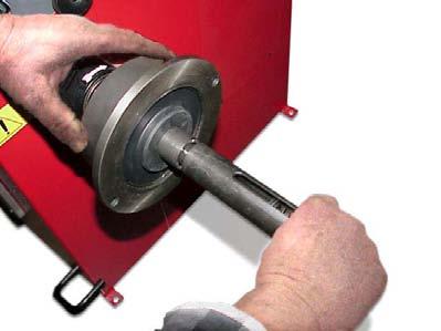
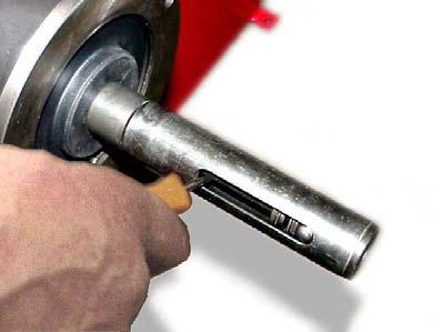
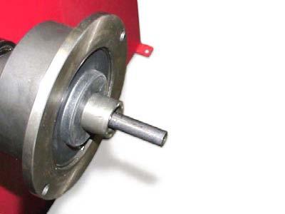
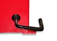
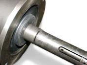
5 3 - START - UP ANCHORING The machine can operate on any flat non resilient floor. Make sure that the machine rests solely on the three support points provided. (Fig.2). If possible, it is advisable to anchor to the floor using relative mounting feet (see fig. 2a) if the machine is continually used with wheels weighing over 35 kg ELECTRICAL CONNECTION The machine is supplied with a single- phase mains cable plus earth (ground). The power supply voltage (and mains frequency) is indicated on the machine identification plate and cannot be changed. Connection to the mains must always be made by expert personnel. The machine must not be set up without proper earthing. Connection to the mains should be through a slow acting safety switch rated at 4A (230V) or 10A (115V). See enclosed diagram PNEUMATIC CONNECTION (Model P) For operation of the spindle with pneumatic locking (costant thrust air spring) connect the wheel balancer to the compressed air main. The connection fitting is located at the back of the machine. At least 7 Kg/cm 2 (~ 0.7 MPa; ~ 7 BAR; ~ 100 PSI) pressure is needed for correct operation of the release device FURTHER SAFETY DEVICES (Model P) - Wheel always locked even when there is pressure failure during the balancing cycle. - Always actuate the unlocking control pedal with the machine stationary in order to avoid stress and abnormal wear on the adapter ADAPTER MOUNTING The wheel balancer is supplied complete with cone type adapter for fastening wheels with central bore. Other optional flanges can be mounted once the terminal part is removed (also see enclosed brochures). N.B.: CAREFULLY CLEAN THE COUPLING SURFACES BEFORE PERFORMING ANY OPERATION. DISASSEMBLY OF THE THREADED END PIECE a) Loosen screw B and remove threaded end-piece A. b) Mount the new adapter. 3 A B I 0318 GB - 5


6 1-2 mm SE2-Mounting 0 mm a b c d e f g SE2_ 0140
. - Avoid using the RL sleeve with metal rims.")
. - Bei Eisenfelgen die Verwendung der Muffe RL vermeiden.")
7 SE2-Dismounting 360 a b c d Cone e - Quando possibile, centrare le ruote con cono dall'interno (vedi disegno). - Evitare di usare il manicotto RL con cerchi di ferro. - Whenever possible, centre the wheels with the cone from the inside (see the drawing). - Avoid using the RL sleeve with metal rims. - Lorsque c est possible, centrer les roues avec le cône de l intérieur (voir dessin). - Eviter d utiliser le manchon RL avec les jantes en fer. - Wenn möglich, die Räder mit Konus von Innen heraus zentrieren (siehe Zeichnung). - Bei Eisenfelgen die Verwendung der Muffe RL vermeiden. - Siempre que sea posible, centrar las ruedas con cono desde dentro (véase dibujo). - Evitar usar el manguito RL con llantas de hierro. SE2_ 0140
8 3.6 - WHEEL GUARD ASSEMBLY AND ADJUSTMENT a) Fasten the components to the base as illustrated in the specific exploded drawing. b) The position of the wheel guard when closed can be adjusted with relative screw accessible at the back. Correct position: horizontal. c) Check that the microswitch is held down when the guard is closed. d) Adjust the angular position of microswitch control SPACER WD/DC (OPTION) When balancing very wide wheels (9 ), there is not enough space to turn the distance gauge. To keep the wheel off the machine side, fit the WD spacer on the flange body and secure it with the standard issue nuts. When centring the wheel with cone from the inside, mount the DC spacer to obtain spring thrust. 4 DC WD Spring Cone I 0318 GB - 8
9 4 - CONTROLS AND COMPONENTS BRAKE PEDAL 5 It allows the operator to hold the wheel when fixing the counterweights. It must not be used during the measuring cycle PNEUMATIC LOCKING PEDAL (Version P) 6 It allows the fixing/releasing of the wheel on the flange. It must not be used during the machine cycle and/or when different flanges are mounted from that with standard cones. The pedal has two stable positions: upper position for unlocking; lower position for locking the wheel MEGASTICK - AUTOMATIC DISTANCE AND DIAMETER GAUGE Allows measuring the distance from the machine and the diameter at the point of application of the counterweight. The same gauge allows proper positioning of the counterweights inside using the specific function which allows reading on the display the position used for the measurement within the rim AUTO SENSE - AUTOMATIC WIDTH GAUGE (OPTION) Width gauging is through a SONAR device which measures the width of the wheel without mechanical contact, simply by closing the guard and each time a valid measurement has been made with the MEGASTICK AUTOMATIC WHEEL POSITIONING At the end of the spin, the wheel is positioned according to unbalance on the outside or static unbalance (when selected). Positioning is disabled automatically for wheels with diameter less than 13. Accuracy is about +/-20 degrees for wheels weighing up to 25 kg. I 0318 GB - 9
10 4.6 - CONTROL PANEL AND DISPLAY / Digital readouts, AMOUNT OF UNBALANCE, inside/outside 3-4 Digital readouts, POSITION OF UNBALANCE, inside/outside 5 Indicators, correction mode selected 6 Indicators, selection made 7 Push button, unbalance reading < 5 g (.25 oz) 8 Push button, operator selection 9 Push button, selection of mode of correction 10 Push button, SPLIT (unbalance spread) 11 Push button, FUNCTION MENU 12 Confirm selection button 13 Push button, cycle start 14 Push button, emergency 15 Push button, manual DISTANCE / DIAMETER / WIDTH setting 16 HOME button 17 AUTO-SELECT button 18 Push button, diameter and width unit of measure selection 19 Push button, unbalance optimization N.B.: Press buttons only with your fingers. Do not use the counterweight pincers or other pointed objects. - When the beep signal is enabled (see FUNCTIONS MENU MANAGEMENT), pressing of any push button is accompanied by a Beep. I 0318 GB - 10
11 HANDLING OF THE FUNCTIONS MENU on/off beep signal guard on/off on/off start from guard closing approx. -5 g or oz CONFIRM CONFIRM CONFIRM CONFIRM See chapter on AUTODIAGNOSTICS 6.1 See chapter on SELF CALIBRATION 6.2 g/oz unit of measure unbalance CONFIRM Calibration of automatic RIM DISTANCE gauge (Only for service-personnel) Calibration of automatic DIAMETER gauge (Only for service-personnel) Calibration of automatic WIDTH gauge (optional) (Only for service-personnel) temperatura Ambient ambiente temperature in CONFIRM (in C C) (opzione) (optional) RETURN TO MEASUREMENT SCREEN I 0318 GB - 11
12 5 - INDICATIONS AND USE OF THE WHEEL BALANCER AUTO SELECT The machine automatically detects the correct balancing program for Steel-, ALU M-, PAX-, and ALU 3M-rims AUTO SELECT FOR STEEL RIMS Move the gauge tip of the MEGASTICK into contact against the rim using the special grip. Hold it in ths position until a beep is heard. 8 Return the MEGASTICK to rest position. The machine has automatically detected the steel rim-mode. b Set the rated width, which is generally indicated on the rim, or measure the width using the compass gauge (standard accessory). Perform a measuring spin, turn the wheel to the correct angles, fix the clip-on weights and perform a control spin. To balance more tyres of the same type and dimensions, the machine automatically stores the data for the current mounted wheel. I 0318 GB - 12
13 AUTO SENSE - AUTOMATIC WIDTH (OPTION) If width measurement by means of the SONAR device is enabled, the following appears at the end of the automatic measurement of the distance and diameter with the MEGASTICK: For large wheels (e.g. off-road vehicles, light trucks or wheels protruding far out from the rim) press the button switch from: to N.T. = NORMAL TYRE L.T. = LIGHT TRUCK Slowly close the wheel guard until a beep is heard. If AUTOMATIC START is enabled when the wheel guard is closed, the wheel balancer spins once to measure the unbalance, otherwise the following appears: Press the button to perform a spin. I 0318 GB - 13
14 AUTO SELECT FOR ALU M AND PAX RIMS 9 Slide out the MEGASTICK to the left side, at the point where an adhesive weight is to be fitted. Hold the MEGASTICK in this position until a beep is heard. Slide it out further towards the right side and wait for the second beep. The machine has automatically detected the ALU M mode. The ALU-M LED lights up. Return the MEGASTICK to rest position and Perform a measuring spin. 10 For the adhesive weight in the left position, turn the wheel to the correct angle, secure the weight in the clamp with the adhesive facing upwards and slide out the MEGASTICK until a beep is heard. Push the clamp upwards until the weight adheres to the wheel. Return the MEGASTICK to the rest position and proceed for the right position in the same way. Move the MEGASTICK further to the right until a beep is heard. Move the MEGASTICK further to the left until a beep is heard. Perform a control spin To balance more tyres of the same type and dimensions, the machine automatically stores the data for the current mounted wheel. To input other dimensions or change the balancing program, press. I 0318 GB - 14
15 AUTO SELECT FOR ALU 3M RIMS 11 Slide out the MEGASTICK to the edge of the rim, at the point where the clip-on weight is to be fitted. Hold the MEGASTICK in this position until a beep is heard. Slide the MEGASTICK further out towards the right side, at the point where an adhesive weight is to be fitted. Wait for the second beep. The machine confirms with ALU 3M To indicate the free choice of the position planes the ALU M LED is also lighting up. NOTE: In very rare cases the difference between the inner and the outer diameter is extremely little. The machine will confirm with ALU M then. For these cases press positions manually. to switch to the ALU 3M Perform a measuring spin For the clip-on weight in the left position turn the wheel to the correct angle and fix the weight manually in the12 o clock position. For the adhesive weight in the right position turn the wheel to the correct angle, secure the weight in the clamp with the adhesive facing upwards, and slide out the MEGASTICK until a beep is heard. Push the MEGASTICK upwards until the weight adheres to the wheel. Push the MEGASTICK further to the right until a beep is heard. Push the MEGASTICK further to the left until a beep is heard. Perform a control spin To balance more tyres of the same type and dimensions, the machine automatically stores the data for the current mounted wheel. To input other dimensions or change the balancing program, press. I 0318 GB - 15
16 ALU 1 & ALU 2 RIMS Input the wheel data as for the steel rims (see AUTO SELECT FOR STEEL RIMS). Perform a measuring spin Press as many times as the LEDS ALU 1 or ALU 2 light up. Fix the weights in correspondence to the points indicated. Perform a control spin. To balance more tyres of the same type and dimensions, the machine automatically stores the data for the current mounted wheel MANUAL PRESETTING (Use only in particular cases or for test) Standard wheels To enable manual dimension setting, hold the button down for at least 3 seconds the first time it is pressed. - Press until a symbol is shown. - With the gauge in rest position, measure the distance wheel-machine (in cm). Set the value substracting 1 cm. - Select by pressing - Set the nominal diameter indicated on the tyre. - Select by pressing - Set the nominal width, which is normally stamped on the rim, or proceed to measure the width with the caliper gauge (supplied as standard). I 0318 GB - 16
17 ALU-M wheels Measure the values according to the diagram hereunder mm SETTING: Select the value to be set by pressing N.B.: Set the values 1 and 2 in cm deducting 1 cm from the value measured. N.B.: Not setting the value of the outside diameter ( ) the system automatically calculates: outside diameter ( ) = 0.8 x inside diameter ( ). I 0318 GB - 17
18 5.3 - RESULT OF MEASUREMENT 12 Inside correction Outside correction After performing a balancing spin, the amounts of unbalance are shown on the digital readouts. Digital readouts with LED s 3-4 lit up indicate the correct angular wheel position to mount the counterweights (12 o clock position). If the audible alarm is enabled (see FUNCTION MENU MANAGEMENT), the acquisition of the correction position is confirmed by a beep alarm. If the unbalance is less than the threshold value selected,, is displayed instead of the unbalance value; with the values below the threshold can be read, selected gram by gram DOUBLE OPERATOR PROGRAM This program allows memorizing the dimensions of two types of wheels. In this way two operators can service two different vehicles at the same time, using the same wheel balancer. The system memorizes two programs with various preset dimensions. 1. Press to select operator (1 or 2). Selection is confirmed by panel-mounted LED. 2. Input the dimensions (see 5.1 AUTO SELECT) 3. Press to carry out the balancing as usual and to store the program. With program 1 or 2 is called for subsequent balancing operations without having to newly enter the dimensions. I 0318 GB - 18
19 5.5 - SPLIT FUNCTION (unbalance spread) The SPLIT function is used to position the adhesive weights behind the wheel spokes so that they are not visible. It is advisable to use this function only in the event of ALU M/PAX or ALU 3M unbalance. Input the wheel dimensions and start a spin. To start the SPLIT function, input the following data: Example of display prior to SPLIT function - Input the number of spokes ( 3-12 ) - Move a spoke at random to the 12 o clock position Place the first split unbalance in correction position Correction position Set the second split unbalance to correction position Correction position 2 To return to normal unbalance display, press the button To perform a new spin, subsequently press the button I 0318 GB - 19
20 5.6 - UNBALANCE OPTIMIZATION - This function serves to reduce the amount of weight to be added in order to balance the wheel - It is suitable for static unbalance of more than 30 g. - It improves the residual eccentricity of the tyre. A) - With a piece of chalk make a reference mark on the flange and the rim - With the aid of a tyre changer, turn the tyre on the rim by Refit the wheel in such a way that the reference marks on the rim and the flange coincide. TYRE POSITION RIM POSITION - Right display: percentage reduction value - Left display: actual static unbalance value which can be reduced by rotation - Mark the two positions of the rim and tyre, and turn the rim on the tyre until the positions correspond in order to obtain the optimization on the display. or RETURN TO MEASUREMENT SCREEN If a spin was not executed before pressing the button the machine requests a spin as follows: The procedure resumes from point A). I 0318 GB - 20
21 5.7 - ALU AND STATIC MODES From the measurement screen, press button or to select the type required. The 5-LED displaysshow the position where to apply the weights. If a spin has already been carried out, each time the mode is changed, the processor automatically recalculates the unbalance values on the basis of the new setting. 13 Button DYNAMIC STATIC DYNAMIC DYNAMIC Balancing of steel or light alloy rims with application of clip-on weights on the rim edges. STATIC Button ALU M/PAX The static mode is necessary for motorcycle wheels or when it is not possible to place the counterweights on both sides of the rim. ALU M ALU 3M ALU 1 ALU 2 ALU M Balancing of alloy rims with hidden application of adhesive weights. ALU 3M Combined application: clip-on weight inside and hidden adhesive weight on outside (Mercedes). ALU - 1 Balancing of light alloy rims with application of adhesive weights on the rim shoulders. ALU - 2 Combined application: adhesive weight outside and clip-on weight inside MINISTAT - AUTOMATIC MINIMIZATION OF STATIC UNBALANCE Initial unbalance sx dx g g Phase shift 50 Possible approximations sx g dx sx dx sx dx sx dx g g g 4 g static residue 3 g 1 g 6 g static residue static residue static residue g g g g With traditional wheel balancer Choice with minimum static unbalance This program is designed to improve the quality of balancing without any mental effort or waste of time by the operator. In fact, using the normal weights available on the market (pitch of 5 in every 5 g) and applying the two counterweights which a conventional wheel balancer rounds to the nearest value, a residual static unbalance of up to 4 g may result. The damage of such approximation is emphasized by the fact that static unbalance is the cause of most disturbances on vehicles. This new function automatically indicates the optimum entity of the weights to be applied by approximating them in an intelligent way according to their position in order to minimize residual static unbalance. If it is not possible to minimize completely the static unbalance keeping in tolerance the dynamic unbalance, this function has the solution to minimize the static unbalance. I 0318 GB - 21
22 6 - SET-UP AUTODIAGNOSTICS DISPLAY TEST - All displays and LEDs should light up in sequence. - Turn the wheel in direction of rotation. The following appears: - Turn the wheel in reverse direction of rotation. The following appears: - In one complete wheel revolution (in direction of rotation), this should appear once - Control parameter (values are not relevant) - Displays values of rim DISTANCE sensor - Displays values of DIAMETER sensor - Displays values of WIDTH sensor (option) END OF AUTODIAGNOSTICS CANCELS AUTODIAGNOSTICS IN ANY PHASE I 0318 GB - 22
23 6.2 - SELF-CALIBRATION For machine self-calibration proceed as follows: - Fit a medium-sized steel wheel on the shaft. Example: 6 x 14 (± 1 ) - Set the exact dimensions of the wheel mounted. CAUTION!! Setting incorrect dimensions will result in the machine not being properly calibrated and hence all the subsequent measurements will be incorrect until a new selfcalibration is performed with the correct dimensions!! - Perform a spin under normal conditions. - Add 100 g (3.5 oz) on the outside in any position. - Shift the 100 g weight from the outside to the inside keeping the same position. - Rotate the wheel WITH the 100 g weight to the 12 o clock position. END OF SELF-CALIBRATION CANCELS SELF-CALIBRATION IN ANY PHASE I 0318 GB - 23
24 7 - ERRORS During machine operation there may be various causes of malfunctioning which, if detected by the microprocessor, are indicated on the display: ERRORS CAUSE CHECKS Err. 1 No rotation signal. 1. Check belt tautness. 2. Check functioning of the phase generator and, in particular, the reset signal. 3. Replace the phase generator. 4. Replace the computer board. Err. 2 Too low speed during measurement. During the unbalance measurement revolutions, the wheel speed has fallen to below 42 rpm. 1. Check that a car wheel has been mounted on the wheel balancer. 2. Check belt tautness. 3. Check functioning of the phase generator and, in particular, the reset signal. 4. Replace the computer board. Err. 3 Unbalance to high. 1. Check the wheel dimension setting. 2. Check the sensor connections. 3. Run the machine calibration function. 4. Mount a wheel with a more or less known unbalance (less than 100 grams) and check the machine response. 5. Replace the computer board. Err. 4 Err. 5 Rotation in opposite direction. After pressing [START], the wheel starts turning in the opposite direction (anticlockwise). Guard open The [START] pushbutton was pressed without first closing the guard. 1. Verify the connection of the UP/DOWN - RESET signals on the phase pick-up board. 1. Reset the error by pressing pushbutton STOP/HOME. 2. Close the guard. 3. Verify the function of the protection-switch. 4. Press the [START] button. Err. 7 / Err. 8 NOVRAM parameter read error 1. Repeat machine calibration 2. Shut down the machine. 3. Wait for at least ~ 1 min. 4. Restart the machine and check proper functioning. 5. Replace the computer board. Err. 9 NOVRAM parameter write error. Replace the computer board. Err. 10 Err. 11 Measured width too small. N.B.: The minimum width the wheel balancer accepts is 1.5 or 40 mm. Too high speed error. During unbalance measurement rotation, wheel speed is more than 270 rpm. 1. Repeat the distance measurement. 2. Repeat the width measurement. 3. Verify the calibration of the distance gauge and replace the distance gauge potentiometer if necessary. 4. Verify the calibration of the width gauge and replace the width gauge potentiometer as necessary. 5. Replace the computer board. 1. Check if there is any damage or dirt on the timing disc. 2. Check functioning of the phase generator and, in particular, the reset signal. 3. Replace the computer board. Err. 12 Unbalance measuring cycle error. 1. Check functioning of the phase generator. 2. Verify correct motor operation. 3. Check belt tautness. 4. Replace the computer board. Err.13/ Err.14/ Err.15/ Err.16/ Err.17/ Err.18 Unbalance measurement error. 1. Check functioning of the phase generator. 2. Check the Piezo-Sensor connections. 3. Check the machine earthing connection. 4. Mount a wheel with a more or less known unbalance (less than 100 grams) and check the machine response. 5. Replace the computer board. Procedure error in automatic distance acquisition in ALU M, ALU 3M and PAX. 1. Pull out the gauge and measure the external side distance. 2. Verify the calibration of the distance gauge. 3. Verify the operation of the distance potentiometer. I 0318 GB - 24
25 7.1 - INCONSISTENT UNBALANCE READINGS It may occur that after balancing a wheel, when removing it from the wheel balancer and then remounting it, the wheel is not balanced. This is not the result of an incorrect indication by the machine, but only of incorrect mounting of the wheel on the flange, i.e. in the two mountings the wheel has assumed a different position with respect to shaft axis of the wheel balancer. If the wheel has been mounted on the flange with screws, it may be that the screws have not been tightened correctly in gradual criss-cross manner one after the other, or (as often occurs) holes have been drilled in the wheel with too wide tolerances. Small errors, up to 10 grams (0.4 oz), are to be considered normal in wheels locked with a cone: the error is normally greater for wheels locked with screws or studs. If, after balancing, the wheel is still unbalanced when refitted on the vehicle, this could be due to the unbalance of the brake drum or very often is due to the screw holes in the rim and the drum drilled with too wide tolerances. In this case a readjustment would be advisable using the wheel balancer with the wheel mounted. 8 - ROUTINE MAINTENANCE Before carrying out any operation on the machine, cut the power supply to the machine REPLACING THE PROTECTION FUSES Some protection fuses are located on the power board (see exploded drawings) accessible by dismantling the weight shelf). If fuses require replacement, use ones with an identical current rating. If the fault persists, contact Technical Service. NONE OF THE OTHER MACHINE PARTS REQUIRE MAINTENANCE. I 0318 GB - 25
26 9 - LIST OF RECOMMENDED SPARE PARTS (For further details, see exploded drawings enclosed) CODE DESCRIPTION Bearing Z Ø 25/47/ Spring 19863P Rigid belt Poly V - TB crested 67M38954C Phase generator board with cable Spring brake lever 24587P 18FC38385 Spiral spring 86SB39034 Cable, automatic rim distance gauge 86SB36493 Cable, automatic diameter gauge 05PR59382 LEXAN Panel Two-pole switch 16A 67M48208A Power board 2 relays/2 sonar Fuses DM 5x20-2A 86SC59519 Computer board 86SB38585 Cable with protective microswitch guard SPECIAL PARTS FOR 230 V MACHINES 50FG55641 Single phase motor 230 V/50-60 Hz Kw 4p HB63D-4 86SZ52433 Complete power board Braking transformer 30VA 230-0/ Capacitor 14MF 450 V FASTON screw M Power supply transformer 40VA 230 SPECIAL PARTS FOR 115 V MACHINE 50FG55643 Single phase motor 115 V/50-60 Hz Kw - 4p HB63D-4 86SZ52434 Complete power board Braking transformer 30VA 115-0/ Capacitor 25MF 450V FASTON screw M Power supply transformer 40VA 115 SPECIAL PARTS FOR SPINDLE SE Bearing LLB/2AV1 (Ø 35/62X14) Bearing Z Ø 35/62X14 18FP29329 Air spring 115 Kg. stroke 75 mm 16FB42177 Ball valve 18FB42639 Automatic pedal spring SPECIAL DETAILS - SONAR WIDTH OPTION 86SB58646 WIDTH Sonar prot. 42 Pneumatic diagram 16SP43470P I 0318 GB - 26
TABLE OF CONTENTS 1 - GENERAL...3
 Instructions for use I TABLE OF CONTENTS Page 1 - GENERAL...3 1.1 - GENERAL SAFETY REGULATIONS...3 1.1.1 - STANDARD SAFETY DEVICES...3 1.2 - FIELD OF APPLICATION...3 1.3 - OVERALL DIMENSIONS...3 1.4- TECHNICAL
Instructions for use CONTENTS
 Instructions for use I CONTENTS 1 - GENERAL 3 1.1 - GENERAL SAFETY REGULATIONS 3 1.1.1 - STANDARD SAFETY DEVICES 3 1.2 - FIELD OF APPLICATION 3 1.3 - OVERALL DIMENSIONS (standard guard) 3 1.4 - TECHNICAL
2 - HANDLING, HOISTING START-UP...4
 Instructions for use I INDEX Page 1 - GENERAL...3 1.1 - GENERAL SAFETY REGULATIONS...3 1.1.1 - STANDARD SAFETY DEVICES...3 1.2 - FIELD OF APPLICATION...3 1.3 - OVERALL DIMENSIONS (standard protection)...3
2 - HANDLING, HOISTING START-UP...5
 Instructions for use I Contents Page 1 - GENERAL...3 1.1 - GENERAL SAFETY REGULATIONS...3 1.1.1 - STANDARD SAFETY DEVICES...3 1.2 - FIELD OF APPLICATION...3 1.3 - OVERALL DIMENSIONS...3 1.4- SPECIFICATION...4
Wheel Products. WP8300 Operators Manual Rev: 910
 Wheel Products by WP8300 Operators Manual Rev: 910 Table of Contents Warranty Page 1 1. General Page 2 General Safety Regulations Page 2 Field of Application Page 2 Overall Dimensions Page 2 Technical
2 - HANDLING, HOISTING START-UP...5
 Instructions for use I Contents Page 1 - GENERAL...3 1.1 - GENERAL SAFETY REGULATIONS...3 1.1.1 - STANDARD SAFETY DEVICES...3 1.2 - FIELD OF APPLICATION...3 1.3 - OVERALL DIMENSIONS...3 1.4- SPECIFICATION...4
2 - HANDLING AND HOISTING COMMISSIONING...5
 Contents Instructions for use Page I 1- GENERAL...3 1.1 - GENERAL SAFETY RECOMMENDATIONS...3 1.1.1 - STANDARD SAFETY DEVICES...3 1.2 - FIELD OF APPLICATION...3 1.3 - OVERALL DIMENSIONS...3 1.4 - SPECIFICATION...4
6275HS Wheel Balancer
 6275HS Wheel Balancer Installation Instructions Operating Instructions Safety Instructions Maintenance Instructions READ these instructions before placing unit in service KEEP these and other materials
Equilibreuses de roues
 Equilibreuses de roues 3607 NOTICE D UTILISATION Notice réf. G-NOT-3607C4 Indice : 0 Instructions for use I TABLE OF CONTENTS Page 1 - GENERAL...3 1.1 - GENERAL SAFETY REGULATIONS...3 1.1.1 - STANDARD
Model 1650 Vibration Control Diagnostic System
 Model 1650 Vibration Control Diagnostic System Operating instructions I Index Page 1- GENERAL...3 1.1 - GENERAL SAFETY RECOMMENDATIONS...3 1.1.1 - STANDARD SAFETY DEVICES...3 1.2 - FIELD OF APPLICATION...3
1. FOREWORD 3 2. TECHNOLOGICAL DESCRIPTION PURPOSE TECHNICAL SPECIFICATIONS DIMENSIONS AND WEIGHTS 6 3.
 GB Use and maintenance manual General Index 1. FOREWORD 3 1.1 GENERAL 3 1.2 PURPOSE OF THE MANUAL 3 1.3 WHERE AND HOW TO KEEP THE MANUAL 3 1.4 MANUAL UPGRADES 3 1.5 COLLABORATION WITH USERS 4 1.6 MANUFACTURER
Instructions for use I 0375 GB - 1
 Instructions for use I INDEX pae 1 - GENERAL...3 1.1 - GENERAL SAFETY REGULATIONS...3 1.1.1 - STANDARD SAFETY DEVICES...3 1.2 - FIELD OF APPLICATION...3 1.3 - OVERALL DIMENSIONS...3 1.4 - TECHNICAL DATA...4
WHEEL BALANCER WITH MICROPROCESSOR FOR CARS, LIGHT COMMERCIAL VEHICLES AND MOTORCYCLES ( Series A )
") 0052-1 HofmannIndustrial GmbH A - 5302 Henndorf Hauptstraße 59 Tel +43-6214-6466-12 \ Fax -20 WHEEL BALANCER WITH MICROPROCESSOR FOR CARS, LIGHT COMMERCIAL VEHICLES AND MOTORCYCLES ( Series A ) Nr. 0052-1998.10
0052-1 HofmannIndustrial GmbH A - 5302 Henndorf Hauptstraße 59 Tel +43-6214-6466-12 \ Fax -20 WHEEL BALANCER WITH MICROPROCESSOR FOR CARS, LIGHT COMMERCIAL VEHICLES AND MOTORCYCLES ( Series A ) Nr. 0052-1998.10
1. FOREWORD 3 2. TECHNOLOGICAL DESCRIPTION PURPOSE TECHNICAL SPECIFICATIONS DIMENSIONS AND WEIGHTS 6 3.
 GB Use and maintenance manual General Index 1. FOREWORD 3 1.1 GENERAL 3 1.2 PURPOSE OF THE MANUAL 3 1.3 WHERE AND HOW TO KEEP THE MANUAL 3 1.4 MANUAL UPGRADES 3 1.5 COLLABORATION WITH USERS 4 1.6 MANUFACTURER
Wheel Balancer Manual(A)
") Wheel Balancer Manual(A) Contents 1.General ----------------------------------------------------------------------------------------------------------------------------------2 2.Machine assembly------------------------------------------------------------------------------------------------------------------------2
Wheel Balancer Manual(A) Contents 1.General ----------------------------------------------------------------------------------------------------------------------------------2 2.Machine assembly------------------------------------------------------------------------------------------------------------------------2
1. FOREWORD 3 2. MACHINE DESCRIPTION PURPOSE TECHNICAL SPECIFICATIONS DIMENSIONS 6 3. STARTING 7 4.
 EN Use and maintenance manual General Index 1. FOREWORD 3 1.1 GENERAL 3 1.2 PURPOSE OF THE MANUAL 3 1.3 WHERE AND HOW TO KEEP THE MANUAL 3 1.4 MANUAL UPGRADES 3 1.5 COLLABORATION WITH USERS 4 1.6 MANUFACTURER
Model 1850 Wheel Balancer
 Model 1850 Wheel Balancer Instructions for use I INDEX page 1 - GENERAL...3 1.1 - GENERAL SAFETY REGULATIONS...3 1.1.1 - STANDARD SAFETY DEVICES...3 1.2 - FIELD OF APPLICATION...3 1.3 - OVERALL DIMENSIONS...3
1. FOREWORD 3 2. MACHINE DESCRIPTION PURPOSE TECHNICAL SPECIFICATIONS DIMENSIONS AND WEIGHTS 6 3. STARTING 7 4.
 GB Use and maintenance manual General Index 1. FOREWORD 3 1.1 GENERAL 3 1.2 PURPOSE OF THE MANUAL 3 1.3 WHERE AND HOW TO KEEP THE MANUAL 3 1.4 MANUAL UPGRADES 3 1.5 COLLABORATION WITH USERS 4 1.6 MANUFACTURER
2 - HANDLING AND HOISTING COMMISSIONING...5
 Instructions for use I CONTENTS pae 1 - GENERAL...3 1.1 - GENERAL SAFETY REGULATIONS...3 1.1.1 - STANDARD SAFETY DEVICES...3 1.2 - FIELD OF USE...3 1.3 - OVERALL DIMENSIONS...3 1.4 - SPECIFICATION...4
1. FOREWORD 3 2. MACHINE DESCRIPTION PURPOSE TECHNICAL SPECIFICATIONS DIMENSIONS 6 3. STARTING 7 4.
 GB Use and maintenance manual General Index 1. FOREWORD 3 1.1 GENERAL 3 1.2 PURPOSE OF THE MANUAL 3 1.3 WHERE AND HOW TO KEEP THE MANUAL 3 1.4 MANUAL UPGRADES 3 1.5 COLLABORATION WITH USERS 3 1.6 MANUFACTURER
 VOLUME 2.0 2 This page intentionally left blank JWB 100 Operator s Manual page 3 Table of Contents 1 Summary 1.1 Features 4 1.2 Specifications 4 2 Installation 2.1 Installation 5 3 Structure 3.1 Main Structure
WHEEL BALANCER INSTRUCTION MANUAL DWC ATTENTION
 WHEEL BALANCER INSTRUCTION MANUAL DWC ATTENTION This manual is an integral part of the product. The warnings and instructions in this manual provide important information about SAFETY IN USE and MAINTENANCE
INSTALLATION, OPERATION AND MAINTENANCE MANUAL
 TW F - 150 Wheel balancing machine INSTALLATION, OPERATION AND MAINTENANCE MANUAL Read this entire manual carefully before installation or operation of the TW F-150. Follow the instructions strictly. 1
Models CB6 Series (CB66-VE)
") Models CB6 Series (CB66-VE) 1. CONTROL PANEL The machine control panel is shown in Figure F1. The control panel allows the operator to give commands and enter or modify data. The same control panel displays
Models CB6 Series (CB66-VE) 1. CONTROL PANEL The machine control panel is shown in Figure F1. The control panel allows the operator to give commands and enter or modify data. The same control panel displays
1. FOREWORD 3 2. MACHINE DESCRIPTION PURPOSE TECHNICAL SPECIFICATIONS DIMENSIONS AND WEIGHTS 6 3. STARTING 7 4.
 GB Use and maintenance manual General Index 1. FOREWORD 3 1.1 GENERAL 3 1.2 PURPOSE OF THE MANUAL 3 1.3 WHERE AND HOW TO KEEP THE MANUAL 3 1.4 MANUAL UPGRADES 3 1.5 COLLABORATION WITH USERS 4 1.6 MANUFACTURER
1. GENERAL INFORMATION
 Instructions for use I Index 1. GENERAL INFORMATION 3 1.1 - GENERAL SAFETY RECOMMENDATIONS 3 1.2 - FIELDS OF APPLICATION 4 1.3 - OVERALL DIMENSIONS 4 1.4 - TECHNICAL DATA 5 2. MOVING THE CABINET 5 3. POWER
INSTALLATION, OPERATION, MAINTENANCE MANUAL KEEP THE MANUAL NEAR THE MACHINE ALL TIME AND MAKE SURE ALL USERS HAVE READ THIS WHEEL BALANCER
 INSTALLATION, OPERATION, MAINTENANCE MANUAL KEEP THE MANUAL NEAR THE MACHINE ALL TIME AND MAKE SURE ALL USERS HAVE READ THIS WHEEL BALANCER FOLLOW THE INSTRUCTIONS CAREFULLY TO GRANT THE MACHINE A CORRECT
2 - HANDLING, HOISTING START-UP...5
 Instructions for use I Contents Page 1 - GENERAL...3 1.1 - GENERAL SAFETY REGULATIONS...3 1.1.1 - STANDARD SAFETY DEVICES...3 1.2 - FIELD OF APPLICATION...3 1.3 - OVERALL DIMENSIONS...3 1.4- SPECIFICATION...4
User's manual Manual por el usuario
 ESPAÑOL FRANÇAIS ITALIANO EN ES User's manual Manual por el usuario ER75TD PORTUGUÊS ESPAÑOL DEUTSCH CEMB S.p.A. Via Risorgimento, 9 23826 Mandello del Lario (LC) ITALY Telefono: + 39 0341 706369 Fax:
K&L MC200 ELITE WHEEL BALANCER Product Manual - MC Wheel Balancing
 Product Manual - MC Wheel Balancing Thank you for purchasing this K&L Product. Please inspect this unit for damage prior to use. This manual will review balancing a motorcycle wheel. Please read the entire
NOTE: THESE PROCEDURES ARE THE SAME AS BEING IN THE SERVICE MODE. NOTE: ONCE THE UNIT IS POWERED DOWN THE VALUES FOR C4 WILL BE GONE.
 SERVICE CODES There are only two service codes that are accessible in a Users Mode. These are C4 (Unbalance Compensation) and C12 (Display Counter Indication). To access these service code in Users Mode
PWB 50 Use and maintenance instruction manual
 PWB 50 Use and maintenance instruction manual English PWB50 INDEX Introduction 5 1.0 Foreword 6 1.1 General 6 1.2 Manual pourpose 6 1.3 Where And How To Keep The Manual 7 1.4 Manual Upgrades 7 1.5 Collaboration
Model 1250 Wheel Balancer
 Model 1250 Wheel Balancer Instructions for use I CONTENTS page 1 - GENERAL...3 1.1 - GENERAL SAFETY RECOMMENDATIONS...3 1.1.1 - STANDARD SAFETY DEVICES...3 1.2 - FIELD OF APPLICATION...3 1.3 - OVERALL
1175 Wheel Balancer. Installation Instructions Operating Instructions Safety Instructions Maintenance Instructions
 1175 Wheel Balancer See Balancing Your First Tire on page 1. Installation Instructions Operating Instructions Safety Instructions Maintenance Instructions READ these instructions before placing unit in
C88 (A) 6-B 8-42-GP 1-BP BP 2-BP 10-LR 3-BP1. * Particolari reperibili in commercio * Parts on the market
 6-B 8-42-GP 1-BP BP 2-BP 10-LR 3-BP1. * Particolari reperibili in commercio * Parts on the market") C88 (A) E-060-C88-GB.PDF 6-B TOUCH 8--GP 1-BP 1.-BP -BP -LR -BP1 D0618-1-BP 0618-1-BP 1-BP MANDRINO PNEUMATICO PNEUMATIC SHAFT ASSEMBLY D08-1.-BP 08-1.-BP 1.-BP TERMINALE SE/C SHAFT END PIECE SE/C D060--BP
C88 (A) E-060-C88-GB.PDF 6-B TOUCH 8--GP 1-BP 1.-BP -BP -LR -BP1 D0618-1-BP 0618-1-BP 1-BP MANDRINO PNEUMATICO PNEUMATIC SHAFT ASSEMBLY D08-1.-BP 08-1.-BP 1.-BP TERMINALE SE/C SHAFT END PIECE SE/C D060--BP
WHEEL BALANCERS & TYRE CHANGERS QUALITY YOU EXPECT AT A PRICE YOU WOULDN T THE STANDARD IN INFORMATION, EQUIPMENT AND DIAGNOSTICS SYSTEMS
 QUALITY YOU EXPECT AT A PRICE YOU WOULDN T THE STANDARD IN INFORMATION, EQUIPMENT AND DIAGNOSTICS SYSTEMS http://diagnostics.snapon.co.uk INTRODUCTION TYRE AND WHEEL BROCHURE The Sun range of Tyre Changers
775/875 Wheel Balancer
 775/875 Wheel Balancer See Balancing Your First Tire on page 1. Installation Instructions Operating Instructions Safety Instructions Maintenance Instructions READ these instructions before placing unit
M1000 (B) - M1000P (B)
 - M1000P (B)") M1000 (B) - M1000P (B) E-0868-0869-M1000-GB.PDF 01-2011 D0854-1 0854-1 1 MANDRINO SHAFT ASSEMBLY D0868-0869-1BP 0856-0857-1BP 1BP MANDRINO PNEUMATICO PNEUMATIC SHAFT ASSEMBLY D0487-1.2BP 0487-1.2BP 1.2BP
M1000 (B) - M1000P (B) E-0868-0869-M1000-GB.PDF 01-2011 D0854-1 0854-1 1 MANDRINO SHAFT ASSEMBLY D0868-0869-1BP 0856-0857-1BP 1BP MANDRINO PNEUMATICO PNEUMATIC SHAFT ASSEMBLY D0487-1.2BP 0487-1.2BP 1.2BP
geodyna 2600 Hofmann Werkstatt-Technik
 geodyna 2600 Operation manual Car wheel balancer Hofmann Werkstatt-Technik Contents Safety rules and function Contents Page. Safety rules and function... 2 2. Installation of the machine... 5 3. Electrical
GLO-1060 (WHEEL BALANCER)
") GLO-1060 (WHEEL BALANCER) OPERATION MANUAL DATE INSTALLED: SERIAL # MANUFACTURING DATE: (EAGLE - GLOBAL : UNITE) -1- GLO-1060 WHEEL BALANCER -2- INDEX 1- Introduction ---------------------------------------------------------------------------------Page
GLO-1060 (WHEEL BALANCER) OPERATION MANUAL DATE INSTALLED: SERIAL # MANUFACTURING DATE: (EAGLE - GLOBAL : UNITE) -1- GLO-1060 WHEEL BALANCER -2- INDEX 1- Introduction ---------------------------------------------------------------------------------Page
DSP Wheel Balancer
 Form 3584T, 02-96 Supersedes Form 3584T, 06-95 OPERATION INSTRUCTIONS DSP9000-9500 Wheel Balancer Copyright 1994-1996 Hunter Engineering Company OWNER INFORMATION Model Number Serial Number Date Installed
Microprocessor wheel balancer equipped with motor S 445. Ed. 03/02. Operating and maintenance instruction manual. Cod
 Microprocessor wheel balancer equipped with motor S 445 Ed. 03/02 Operating and maintenance instruction manual Cod. 3007600 DECLARA ARATION DE CONFORMITE CE CE DECLARA ARATION OF CONFORMITY DICHIARAZIONE
Operating Instructions. Angle Seat Control Valve. Type 7020
 Operating Instructions Angle Seat Control Valve Type 7020 With: Digital Positioner Type 8048 Electro-pneumatic Positioner Type 8047 Pneumatic Positioner Type 8047 Version: 02/2006 Manual-7020e.doc Art.-No:
CATALOGUE 1. Introduction Specification and Features Specification Features Working Environment
 CATALOGUE 1. Introduction... 3 2. Specification and Features... 3 2.1 Specification... 3 2.2 Features... 3 2.3 Working Environment... 4 3. The Constitution of Dynamic Balancer... 4 3.1 Machine... 4 3.2
ProRide Diagnostic ProRide Diagnostic PL Wheel Balancer Models
 ProRide Diagnostic ProRide Diagnostic PL Wheel Balancer Models See Balancing Your First Tire on page 5. Safety Instructions Set-up Instructions Operation Instructions Maintenance Instructions READ these
Control Panel...3 Special Key Functions...4 Switching From Grams to Ounces...4 Calibration...5
 1 INDEX PAGE Control Panel...3 Special Key Functions...4 Switching From Grams to Ounces...4 Calibration...5 2 Function Press to switch between static and dynamic balancing modes. Aluminum Mode Press to
2006 MINI Cooper SUSPENSION Wheels & Tires - Repair Instructions - Cooper (1.6L) R50/W10 & Cooper S
 R50/W10 & Cooper S") WHEELS 2002-05 SUSPENSION Wheels & Tires - Repair Instructions - Cooper (1.6L) R50/W10 & Cooper S 36 10 300 REMOVING OR INSTALLING FRONT OR REAR WHEEL NOTE: For Special Tool identification, see WHEEL AND
WHEELS 2002-05 SUSPENSION Wheels & Tires - Repair Instructions - Cooper (1.6L) R50/W10 & Cooper S 36 10 300 REMOVING OR INSTALLING FRONT OR REAR WHEEL NOTE: For Special Tool identification, see WHEEL AND
180 PRO3DAUTO 3DTECHNOLOGY EQUIPPED WITH AUTOMATIC WHEEL DIMENSION SONAR AND LASER RIM PROFILE SCANNER ELECTRONIC WHEEL BALANCERS WITH MICROPROCESSOR
 WHEEL BALANCERS 180 PRO3DAUTO EQUIPPED WITH AUTOMATIC WHEEL DIMENSION SONAR AND LASER RIM PROFILE SCANNER 3DTECHNOLOGY ELECTRONIC WHEEL BALANCERS WITH MICROPROCESSOR AUTOMATIC BALANCING MODE Perfect balancing
NTB-550 Manual. Contents
 1 NTB-550 Manual Please read this Manual before using the Machine. You will need to know the safety instructions, System Settings, Wheel Parameters Input and Calibration process before you can properly
Type 3761 Pneumatic or Electropneumatic Positioner for Rotary Actuators. Fig. 1 Type 3761 Positioner. Mounting and Operating Instructions EB 8386 EN
 Type 3761 Pneumatic or Electropneumatic Positioner for Rotary Actuators Fig. 1 Type 3761 Positioner Mounting and Operating Instructions EB 8386 EN Edition July 2007 Contents Contents Page 1 Design and
Operating & Maintenance Instructions Thermobend Elite Range
 Operating & Maintenance Instructions Thermobend Elite Range Table of Contents 1. Setting Up... 2 1.1 Introduction... 2 1.2 Location & Assembly... 4 1.3 Electrical Supply & Connection... 5 1.4 Pneumatic
S 820. Giuliano Industrial S.p.A.
 Digital electronic wheel-balancer with adjustable LED display Digital electronic wheel-balancer with adjustable LED display. Equipped with balancing programs for wheels with alu-rims, static and dynamic
M ALU-S
 CATALOGUE 1. Introduction...1 2. Specification and Features...1 2.1 Specification... 1 2.2 Features... 1 2.3 Working Environment... 1 3. The Constitution of Dynamic Balancer...1 3.1 Machine... 1 3.2 Electricity
SAFETY INFORMATION. For your safety, read this manual thoroughly before operating the EEWB300A Wheel Balancer
 SAFETY INFORMATION For your safety, read this manual thoroughly before operating the EEWB300A Wheel Balancer The Model EEWB300A Wheel Balancer is intended for use by properly trained automotive technicians.
INSTRUCTION MANUAL G 2000RC. \Jï::) YAESU MUSEN CO., LTD. \ "I// C.P.O. BOX vv TOKYO, JAPAN
 YAESU MUSEN CO., LTD. \ I// C.P.O. BOX vv TOKYO, JAPAN") INSTRUCTION MANUAL G 2000RC \Jï::) YAESU MUSEN CO., LTD. \ "I// C.P.O. BOX 1500 vv TOKYO, JAPAN Y AESU G-2000RC HEAVY- DUTY ANTENNA ROTATOR & CONTROLLER The Yaesu G-2000RC is designed to support and rotate
INSTRUCTION MANUAL G 2000RC \Jï::) YAESU MUSEN CO., LTD. \ "I// C.P.O. BOX 1500 vv TOKYO, JAPAN Y AESU G-2000RC HEAVY- DUTY ANTENNA ROTATOR & CONTROLLER The Yaesu G-2000RC is designed to support and rotate
**Detailed instructions for balancing aluminum wheels in Section 15 of manual.
 PWB-1530 Manual Please read this Manual before using the Machine. You will need to know the safety instructions, System Settings, Wheel Parameters Input and Calibration process before you can properly
1. introduction 3 2. Wheel bearing special features 4 3. Wheel bearing units from an economical point of view 5
 Motor chassis Service Technical BROCHuRE Wheel Bearing Repair Solutions for Light Commercial Vehicles CONTENT 1. introduction 3 2. Wheel bearing special features 4 3. Wheel bearing units from an economical
Wheel Balancers. Safety Instructions Set Up Instructions Operation Instructions Maintenance Instructions
 Wheel Balancers See Balancing Your First Tire on page 7. Model 350 Shown Safety Instructions Set Up Instructions Operation Instructions Maintenance Instructions Model 550 Shown READ these instructions
WORKSHOP EQUIPMENT. Tyre changers Recommended by Volkswagen AG
 WORKSHOP EQUIPMENT Tyre changers VAS 6313-C and VAS 6314-C wdk-certified Tyre changer VAS 6313-C Certified by wdk for handling of UHP and run-flat tyres. With pneumatic mounting tool VAS 6312-1 and kit
WP37 & HT37 User Manual
 WP37 & HT37 User Manual Origio WP37 & HT37 Warming Plates & Heated Trolley Warming Plates WP37 300 WP37 500 Heated Trolley HT37 Origio WP37 Component Description Heated work surface Model WP37 300 Power
Operating manual and installation instructions ENGLISH. Electronic engine remote control. Copyright 2001 Vetus den Ouden n.v.
 Operating manual and installation instructions ENGLISH Electronic engine remote control Copyright 00 Vetus den Ouden n.v. Schiedam Holland Contents Introduction... General conditions of use... Operating....
Pneumatic or Electropneumatic Positioner for Rotary Actuators Type Fig. 1 Type 3761 Positioner. Mounting and Operating Instructions EB 8386 EN
 Pneumatic or Electropneumatic Positioner for Rotary Actuators Type 3761 Fig. 1 Type 3761 Positioner Mounting and Operating Instructions EB 8386 EN Edition June 2004 Contents Contents Page 1 Design and
Operating Instructions. Pneumatic Control Valve Low Temperature. Type Series GS3
 Operating Instructions Pneumatic Control Valve Low Temperature Type 8026 Series GS3 With: Digital Positioner Type 8048 Electro-pneumatic Positioner Type 8047 Pneumatic Positioner Type 8047 Version: 03/2006
POMPE AUTOADESCANTI SELF-PRIMING ELECTRO PUMP ACM DISASSEMBLY AND ASSEMBLY INSTRUCTIONS FOR MULTISTAGE SELF-PRIMING PUMPS
 POMPE AUTOADESCANTI SELF-PRIMING ELECTRO PUMP ACM DISASSEMBLY AND ASSEMBLY INSTRUCTIONS FOR MULTISTAGE SELF-PRIMING PUMPS Ed. 02/2011 5 WARNING These instructions are for the maintenance personnel for
Model 8.6 and Model 8.7 High Performance Wheel Balancer Operation Instructions FORM #5608
 â 7 Model 8.6 and Model 8.7 High Performance Wheel Balancer Operation Instructions FORM #5608 (BLANK PAGE) Page 2 â John Bean Company 309 Exchange Avenue Conway, AR 72032 USA Phone (501) 450-1500 Fax (501)
Axial-radial cylindrical roller bearings
 Axial-radial cylindrical roller bearings Designs and variants.............. 320 Bearing data..................... 321 (Boundary dimensions, tolerances) Product table 5.1 Axial-radial cylindrical roller
Kerosene - oil burner
 Installation, use and maintenance instructions Kerosene - oil burner Two stage operation CODE MODEL TYPE 3746686 G0D 76T8 90 (0) TECHNICAL FEATURES Thermal power output 44 / 54 0 kw 3.7 / 4.5 0 kg/h Fuel
NTB-800 Manual. Contents
 NTB-800 Manual Please read this Manual before using the Machine. You will need to know the safety instructions, System Settings, Wheel Parameters Input and Calibration process before you can properly balance
INSTRUCTION & MAINTENANCE MANUAL. Read this entire manual carefully before installation or operation of the TW F-95. Follow the instructions strictly.
 TW F-95 Wheel balancing machine INSTRUCTION & MAINTENANCE MANUAL Read this entire manual carefully before installation or operation of the TW F-95. Follow the instructions strictly. I II CATALOGUE V2016.08
Wheel Balancers. b9005. Digital wheel balancer for small garages and service stations
 b9005 Digital wheel balancer for small garages and service stations Hand-spin wheel balancer Including many patented features such as virtual plane imaging technique (VPI), adhesive wheel weight clamp,
Control Panel...3 Special Key Functions...4 Switching From Grams to Ounces...4 Calibration...5 Automatic Gauge Calibration...11
 INDEX PAGE Control Panel...3 Special Key Functions...4 Switching From Grams to Ounces...4 Calibration...5 Automatic Gauge Calibration...11 2 Function Press to switch between static and dynamic balancing
Quality Stainless Products DB-8000-XL Strut Compressor
 Quality Stainless Products DB-8000-XL Strut Compressor Thank you for choosing Quality Stainless Products DB-8000-XL, Strut Compressor. In order to operate your new Strut Compressor safely, we suggest you
LINEAR ACTUATORS INDEX
 LINEAR ACTUATORS INDEX Linear actuators LMR Series LMR 01 thrust force up to 1 300 N DC motor... page 2 LMR 03 thrust force up to 6 000 N DC motor... page 3 Linear actuators ATL Series ATL 02 thrust force
Oil - kerosene burner
 Installation, use and maintenance instructions Oil - kerosene burner One stage operation CODE MODEL TYPE 374445 G5 444T50 9038 () TECHNICAL FEATURES Thermal power output 8 0 kw.3 5 kg/h Fuel Gas oil 35s,
VAS 6230B Road Force Touch. Customized for All Audi, Bently, Seat, Skoda and Volkswagen Vehicles NEW!
 VAS 6230B Road Force Touch Customized for All Audi, Bently, Seat, Skoda and Volkswagen Vehicles VAS 6230B at a glance ow With More Speed!* 3 Perform a Road Force test and balance faster than a traditional
Declaration of Conformity
 Declaration of Conformity We, Manufacturer: Spartanics Ltd. 3605 Edison Place Rolling Meadows, Illinois 60008 Phone: 847-394-5700 Fax: 847-394-0409 USA ENGLISH declare under our sole responsibility that
SECTION 25 FRONT AXLE. Chapter 2 Terraglide (Front Axle Suspension)
") SECTION 25 MECHANICAL FRONT AXLE CHAPTER 2 1 SECTION 25 FRONT AXLE Chapter 2 Terraglide (Front Axle Suspension) CONTENT Section Description Page 25 000 Specifications................................................................
SECTION 25 MECHANICAL FRONT AXLE CHAPTER 2 1 SECTION 25 FRONT AXLE Chapter 2 Terraglide (Front Axle Suspension) CONTENT Section Description Page 25 000 Specifications................................................................
Quarter turn actuator DAPS..R..-F..
 Quarter turn actuator DAPS..R..-F.. Festo AG & Co. KG Postfach D-73726 Esslingen +49 711 347-0 www.festo.com (en) Operating instructions 8030408 1309g [8030416] Original: de Quarter turn actuator DAPS..R..-F.....
Contents. Page. 1. Product description. 2. The AXC line of linear axes. 3. AXLT line of linear tables. AXC and AXS product overview...
 SNR Industry Contents Page 3 1. Product description AXC and AXS product overview... 6-8 Dynamic load ratings of the linear motion systems... 9 Compact modules... 10-11 Linear tables... 12 Telescopic axes...
KEWTECH. KT56 digital multi function tester. Instruction manual
 KEWTECH KT56 digital multi function tester Instruction manual Contents 1 Safety Notice 1 2 Features and Principles of Measurement 3 3 Introduction 6 4 Specifications 7 5 Instrument layout 9 6 Operating
Installation and operating manual Quick closing valve (Bellow sealed) LK product no:
 LK product no:") LK product no: 902002 Article no: 74506 Revision: 2 Contents 1. General information... 3 2. Safety precautions... 3 2.1 Significance of symbols... 3 2.2 Explanatory notes on safety information... 3 3.
LK product no: 902002 Article no: 74506 Revision: 2 Contents 1. General information... 3 2. Safety precautions... 3 2.1 Significance of symbols... 3 2.2 Explanatory notes on safety information... 3 3.
Digitrip Retrofit System for ITE K-3000, K-3000 S, K-4000 and K-4000 S Breakers
 Supersedes IL 33-858-4 Dated 05/02 Digitrip Retrofit System for ITE K-3000, K-3000 S, K-4000 and K-4000 S Breakers Digitrip Retrofit System for ITE K-3000, Digitrip Retrofit System for ITE K-3000, K-3000
Double piston rotary drive DRQD-6/... / b [ ] (en) Operating instructions
![Double piston rotary drive DRQD-6/... / b [ ] (en) Operating instructions](/thumbs/95/124095546.jpg "Double piston rotary drive DRQD-6/... / b [ ] (en) Operating instructions") Double piston rotary drive (en) Operating instructions 8068584 2017-05b [8068586] Original instructions Symbols: Warning, Caution Fitting and commissioning to be carried out by qualified personnel only
Double piston rotary drive (en) Operating instructions 8068584 2017-05b [8068586] Original instructions Symbols: Warning, Caution Fitting and commissioning to be carried out by qualified personnel only
 www.motiontech.com.au Copyright SERVOMECH This catalogue contents are under publisher copyright and may not be reproduced unless permission is agreed. Every care has been taken to ensure the accuracy of
FAG Wheel Bearing Repair Solution for Light Commercial Vehicles
 FAG Wheel Bearing Repair Solution for Light Commercial Vehicles Mercedes-Benz Sprinter, Viano, Vito and Volkswagen Crafter Front Axle The content of this brochure shall not be legally binding and is for
Copyright Information. Trademark Information. General Notice. owners. LAUNCH disclaims any and all rights in those marks.
 LAUNCH Copyright Information KWB-4xx User s Manual owners. LAUNCH disclaims any and all rights in those marks. All rights reserved! No part of this publication may be reproduced and stored in any form
KEYSTONE FIGURE 79 PNEUMATIC ACTUATOR OPERATING AND MAINTENANCE INSTRUCTIONS
 Operating and Maintenance Instructions for: Figure 79 Pneumatic Actuators (U/E options) Double Acting Actuator 4. If pipelines are hydraulically tested, then the lines should be blown down with high pressure
Fisher 2052 Diaphragm Rotary Actuator
 Instruction Manual 2052 Actuator Fisher 2052 Diaphragm Rotary Actuator Contents Introduction... 1 Scope of Manual... 1 Description... 1 Specifications... 4 Installation... 4 Actuator Mounting and Changing
MODEL 520 REMOTE START ENGINE MANAGEMENT SYSTEM
 MODEL 520 REMOTE START ENGINE MANAGEMENT SYSTEM DSE 520 ISSUE 4 4/4/02 MR 1 TABLE OF CONTENTS Section Page INTRODUCTION... 4 CLARIFICATION OF NOTATION USED WITHIN THIS PUBLICATION.... 4 1. OPERATION...
Mounting and operating instructions EB 5801 EN. Electric Actuators Type 5801 (Rotary Actuator) Type 5802 (Linear Actuator)
 Type 5802 (Linear Actuator)") Electric Actuators Type 5801 (Rotary Actuator) Type 5802 (Linear Actuator) Linear Actuator with Type 3260 Control Valve Rotary actuator with lever system Linear actuator with Type 3321 (V2001) Control
Electric Actuators Type 5801 (Rotary Actuator) Type 5802 (Linear Actuator) Linear Actuator with Type 3260 Control Valve Rotary actuator with lever system Linear actuator with Type 3321 (V2001) Control
Installation and Operating Instruction for Brake Caliper HW 150 HFA and HW 180 HFA E e
 Installation and Operating Instruction for Brake Caliper HW 150 HFA and HW 180 HFA E 09.736e Schaberweg 30-38 Phone +49 6172 275-0 61348 Bad Homburg Fax +49 6172 275-275 Germany www.ringspann.com info@ringspann.com
WORKSHOP EQUIPMENT. Recommended by Volkswagen AG
 WORKSHOP EQUIPMENT WORKSHOP EQUIPMENT Recommended by Volkswagen AG BALANCING TECHNOLOGY AT ITS FINEST VAS 741 055 VAS 6309 Digital car wheel balancer with geotouch display Digital wheel balancer with large
geodyna The Fully Automatic Wheel Balancer with 3D Laser Technology
 geodyna The Fully Automatic Wheel Balancer with 3D Laser Technology Optimum Use of Laser Technology What is geodyna OPTIMA? The geodyna OPTIMA is a diagnostic wheel balancer using a patented non-contact
SIT-LOCK self locking elements
 self locking elements Advantages of on the shaft-hub connection compared with traditional systems Easy assembly and disassembly Both actions take place by locking and unlocking the clamping screws with
Centrifuge Operator / Service Manual
 3000 Centrifuge Centrifuge Operator / Service Manual cat.# 26230 & 26231 The Q-sep 3000 centrifuge complies with all requirements of UL standard 3101 20, Can/CSA C22.2 No. 1010.1, and Can/CSA C22.2 No.
Mounting and Operating Instructions EB 8097 EN. Pneumatic Control Valves Type and Type
 Pneumatic Control Valves Type 3347-1 and Type 3347-7 Hollow-mold cast body with welding ends Full-mold cast body with threaded connections Fig. 1 Type 3347-7 Control Valve with Type 3277 Actuator and integral
New car Wheel Balancers for car, van and motorcycle wheel
 The MONDOLFO FERRO balancer range has been improved with the new model, presented to the public for the first time during Autopromotec and available for sale already since September. 32 The new completed
geodyna & WHEEL BALANCERS
 geodyna & WHEEL BALANCERS montytyre CHANGERS excellence in wheel service For performance that never falters Built on a strong foundation of German engineering, HOFMANN has been providing leading-edge technology
OPERATING MANUAL Digital Diesel Control Remote control panel for WhisperPower generator sets
 Art. nr. 40200261 OPERATING MANUAL Digital Diesel Control Remote control panel for WhisperPower generator sets WHISPERPOWER BV Kelvinlaan 82 9207 JB Drachten Netherlands Tel.: +31-512-571550 Fax.: +31-512-571599
Service Manual W365H, W375H, W3105H, W3130H, W3180H, W3240H, W3300H Exacta
 Service W365H, W375H, W3105H, W3130H, W3180H, W3240H, W3300H Exacta 438 9201-81/EN 06.42 Overview Safety precautions Technical data Machine presentation 1 2 3 4 5 Service instructions Machine components