Powered by Safety Powell GIS Type G81 Switchgear
|
|
|
- Abraham Eaton
- 6 years ago
- Views:
Transcription


1 Powell GIS Type G81 Switchgear Application Guide for Powell GIS IEC Switchgear
2 TABLE OF CONTENTS Introduction 1 Switchgear Design 2 Standards 2 Normal Operating Conditions 2 Environmental Conditions 2 Degree of Protection 2 General Description 3 Section Design and Compartments 3 Low Voltage Compartment 3 Vacuum Circuit Breaker 4 General 4 Classification 5 Control and Auxiliary Circuit 5 Interlocking 5 Switchgear Accessories 5 Ratings 6 Section Component Identification 7 7 Typical Section Views 8 Guide Specification 10 Contact Us 16


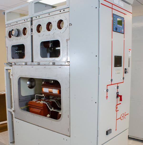
3 1 INTRODUCTION A POWELL PROVEN SOLUTION Powell GIS Type G81 switchgear combines proven GIS design with Powell superior technical integration capabilities. The factory assembled GIS switchgear can be incorporated into any of Powell s integrated turnkey solutions. This includes all switchgear engineering design, integration, control and monitoring capabilities. World class GIS custom-engineered switchgear complimented by Powell s proven project management and support will continue to deliver a safe and reliable operation under the most critical service conditions. We can meet your most demanding requirements. COMPACT, SAFE AND CLIMATE INDEPENDENT By combining SF 6 gas insulation, vacuum interrupter technology and arc-resistant design; the Powell GIS solution extends safety for equipment and personnel to a maximum. All live parts are enclosed within SF 6 gas at the factory during the manufacturing process, eliminating the need for gas handling during installation and commissioning. With all current-carrying parts sealed in a laser-welded compartments, your project receives the benefit of a compact, space-saving design and equipment with a low maintenance requirement.
4 2 SWITCHGEAR DESIGN STANDARDS Powell GIS Type G81 switchgear is manufactured and has been design tested to following IEC standards. Switchgear Device Degree of Protection SF 6 Gas Insulation Transformer Powell GIS IEC IEC Circuit Breaker IEC Position Switch IEC Fuse Combination Switch IEC IEC Specification IEC Diagnosis Guide IEC Current Transformer IEC Voltage Transformer IEC NORMAL OPERATING CONDITIONS The rated current is based on the normal operating conditions for indoor switchgear with an ambient temperature range from -5 C to +40 C. If the ambient temperature is higher than +40 oc, the permissible current is different from the rated current (please consult factory for appropriate derating details). However, the maximum ambient temperature should not be higher than +55 oc. ENVIRONMENTAL CONDITIONS All live parts in the circuit breaker and bus bar compartments are sealed by gas-tight enclosure of IP65. These compartments are safe to touch and suitable for applications under aggressive ambient conditions such as salt, humidity, dust and condensation. The compartment design provides protection from small animals. SF 6 gas is a non-flammable, non-toxic and a non-ozone depleting insulating medium. DEGREE OF PROTECTION Protection against entry of hazardous parts and water according to the IEC and IEC following degree of protection. High Voltage Live Parts Low Voltage Compartment IP65 IP4X GENERAL DESCRIPTION Dust-tight and protected against water jet Protected for a diameter or strips of a thickness greater than 1.0 mm The switchgear is an indoor gas-insulated and metalenclosed 3-phase cubicle design with segregated SF 6 insulated compartments for circuit breaker and bus systems. Configurations are available with single or double bus systems. It is suitable for local and remote control. The high voltage elements consist of two or three gastight stainless steel tanks (SUS 304L), built as a sealed pressure system. Each of the gas compartments has a filling valve, gas monitoring by means of a pressure sensor, and its own pressure relief system. With non bolted plug-in bus bar connections, Powell GIS does not require any handling of SF 6 gas at the jobsite. The power cables enter from the bottom and connect to the switchgear by means of plug-in connectors. An optional test socket is available for cable testing and current and voltage injection. The cable compartment has a pressure relief system leading to the pressure relief duct. The switchgear is designed for a maximum leakage rate of 0.1% per year. The gas tanks are constructed utilizing state-of-the art manufacturing techniques out of laser cut and welded stainless steel. The operation safety and insulation properties (power frequency voltage and BIL) are still maintained even in case the gas drops to atmospheric pressure at sea level.
5 3 GENERAL DESCRIPTION (CONT.) For operator safety the switchgear has an active and passive protection system against internal faults in each partitioned gas compartment. The passive safety section ensures that hot gases generated in the vent of an internal arc fault are directed via pressure relief disks from each SF 6 compartment and into the pressure relief duct system. The pressure relief duct is guided outside of the building or vented to an area to prevent harm to personnel. This maximizes safety to personnel and risk of fire. Switchgear gas tank components have been type tested to IEC , IAC class BFLR at 40kA, 1s. The temperature-compensated sensors for pressure measurement are used to continuously monitor the SF 6 gas tank compartment pressure. Theses sensors provide operator warning in the event of pressures outside the normal operating window. The high voltage switchgear components do not require maintenance for the life of the equipment when applied under normal operating conditions. The circuit breaker drive mechanisms are accessible for inspection and maintenance and do not require opening any portion of the gas enclosed components. Pressure relief duct must be provided for all high voltage SF 6 gas filled compartments. This duct may not utilize the cable connection space or be vented below the switchgear through a false floor or similar design. LOW VOLTAGE COMPARTMENT The low voltage compartment is a self-contained assembly and all operating mechanisms are motorized. Manual emergency operation and mechanical position indicators are provided. Normal operation such as switching, reading of measurements and messaging is possible without special instruction or operator training. The low voltage compartment can also contain a custom-engineered Powell Automation control and monitoring solution designed specifically to meet your application. Powell provides custom-engineered automation solutions ranging from transfer schemes to power management and load-shed applications. Our proven experience includes oil and gas production, refineries, power generation, mining, and data centers. Around the world today, varying degrees of control and monitoring philosophies are rapidly being implemented. Our experience and application knowledge of intelligent electronic devices (IEDs) and networking solutions allows us to engineer a modern, open architecture system for your control and monitoring needs. Powell also provides embedded resources to ensure a successful project integration and delivery. Contact our application team today! SECTION DESIGN AND COMPARTMENTS The switchgear sections are divided into the following compartments: 1. Core sealed SF 6 gas compartment containing vacuum circuit breaker, current transformers and current/voltage sensors. 2. Bus sealed SF 6 gas compartment with built-in 2 or 3 position switches. 3. Open air cable termination compartment including provisions for conventional voltage transformer plug-in connection. 4. Open air low voltage compartment to house secondary control devices, meters, relays and other monitoring equipment.

6 4 VACUUM CIRCUIT BREAKER GENERAL The circuit breakers are three-pole vacuum interrupter type and comply with IEC Publication Within the core gas compartment the vacuum circuit breaker is stationary mounted. Type test certificates can be supplied upon request. The high voltage part of the circuit breaker is maintenance-free for life time under normal operating conditions as specified by IEC The circuit breaker drive mechanism does require periodic maintenance and is accessible from the front of the switchgear without having to enter or depressure any SF 6 gas filled compartment. First maintenance interval occurs after 10 years service. All circuit breakers are subjected to routine testing in accordance with IEC The circuit breaker is equipped as follows: 1. Stored energy spring mechanism for motor charging and emergency manual operation 2. Mechanical push buttons for closing and opening 3. Mechanical indicators for switch position and mechanism position 4. Mechanical operations counter 5. Shunt release OFF 6. Shunt release ON 7. Switch positions are determined by wear and tear free proximity sensors. The vacuum interrupters retain high dielectric strength and short-circuit breaking capability with a vacuum of 10-7 mbar. They are mounted rigidly so as to be able to withstand the forces generated by switching operation and contact pressure. The operating mechanism is motor-charged, spring stored-energy type and consists of a charging mechanism, closing spring, trip spring, motor, solenoids, auxiliary switches, spring-charged indicator and on/off indicator. The released closing spring is automatically recharged by the charging motor and capable of the operating sequence openclose-open which is required when unsuccessful autoreclosing operation is attempted. 1 - Close/Open Indicator 2 - Manual Open Pushbutton 3 - Manual Close Pushbutton 4 - Operations Counter 5 - Hole for Manual Charging 6 - Spring Charge Indicator 7 - Charging Mechanism 8 - Closing Spring 9 - Trip Spring 10 - Contact Pressure Spring 11 - Tripping Coil (Y1) 12 - Closing Coil (Y9) 13 - Auxiliary Switch (S1) 14 - Motor (M1) 15 - Vacuum Interrupter 16 - VI Housing 17 - Mechanism Housing
7 5 CLASSIFICATION Mechanical Endurance M2 Electrical Endurance E2 Capacitive Current Switching Type G81 Circuit Breaker Class C2 S2 10,000 times with minimal maintenance No maintenance of the interrupting parts Very low probability of re-strike Used in cable and line systems SWITCHGEAR ACCESSORIES The following Switchgear accessories are provided for each switchgear assembly. 1. Handle for disconnector mechanism 2. Handle for grounding switch mechanism 3. Hand crank for circuit breaker manual charge 4. Padlockable pushbutton cover for disconnector, ground switch, and circuit breaker CONTROL AND AUXILIARY CIRCUIT Charging Motor Closing Coil Opening Coil Auxiliary Contact 500 VA at DC 110V / 220V 150 VA at DC 110V / 220V 300 VA at DC 110V / 220V 6NO, 6NC or 10NO,10NC INTERLOCKING In order to ensure proper operation and maximize safety, a series of interlocks is provided to protect the operators and the switchgear.. The protection against improper operation is accomplished electrically or by software in case of a multifunctional control and protection unit. The following interlocking dependencies are provided: 1. Limit position blocking of the switching devices. 2. Interdependence of disconnector and earthing switch in the same panel. 3. Interdependence of the disconnector and the circuit breaker in the same panel. 4. Interdependence of the circuit breaker and the earthing switch in the same panel. 5. Dependence of the disconnector on the bus coupler circuit breaker and vice versa.
8 6 RATINGS The Type G81 switchgear is designed for use up to 36kV for single or double bus according to IEC Type of available panels: Incoming/outgoing feeder Bus section and bus riser Bus coupler Bus VT panel Rated Voltage (kv) up to 36 Power Frequency Withstand Voltage (kv) up to 80 Lightning Impulse Withstand Voltage (kv) up to 170 Rated Frequency (Hz) 50 / 60 Normal Current (A) Main Bus 3150 Feeder 630/1250 / 2000 / 2500 / 3150 Rated Short Time Withstand Current, 3s (ka) 40 Rated Peak Withstand Current (ka, peak) 104 Rated Short Circuit Breaking Current (ka) 40 Rated Short Circuit Making Current (ka) 104 Rated Operating Sequence O-0.3s-CO--15s-CO Closing Time (ms) 70 Opening Time (ms) 50 Breaking Time (cycles) 3, 5 Auxiliary Voltage (V) DC110 / Insulation Gas SF 6 Rated Pressure at 20 oc (bar) 0.4 Minimum Operating Pressure at 20 oc (bar) 0.3 Arc Classification BFLR, 40kA / 1s Bus Bar System Single / Double 1250A 23.6/600, 31.5/800 3 Width (W) 2000A 31.5/800 Size (inches/mm) 2 Depth (D) 69.3/1760, 77.2/ Height (H) 94.5/2400 Notes: 1 - The auxiliary voltage can be changed on request. 2 - The size of actual panel can be different according to the rating, quantity and arrangement of components. 3 - Width of the panel when voltage transformer is installed. 4 - Depth of the panel can increase according to the numbers and size of components in low voltage compartment.
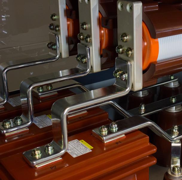
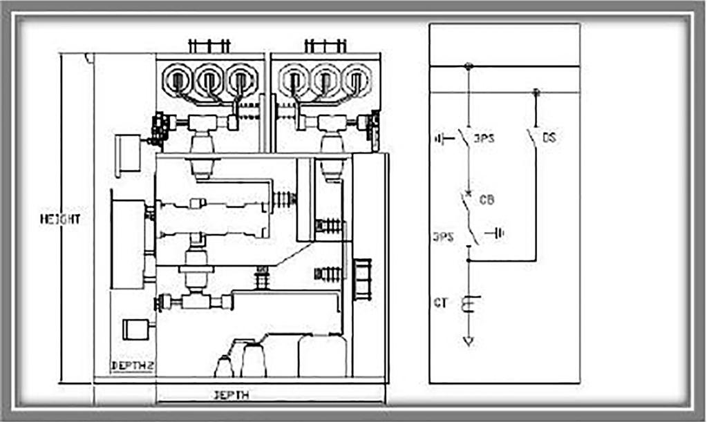
9 7 SECTION COMPONENT IDENTIFICATION SINGLE BUS CROSS SECTION a b c d e f g h i j k a. Main Bus b. Position Switch c. 3-Position Switch Mechanism d. Bushing e. Vacuum Interrupter f. Rupture Disc g. Circuit Breaker Mechanism h. Current Transformer (Block Type) i. Inner Cone Socket j. Surge Arrestor k. Zero Sequence Current Transformer


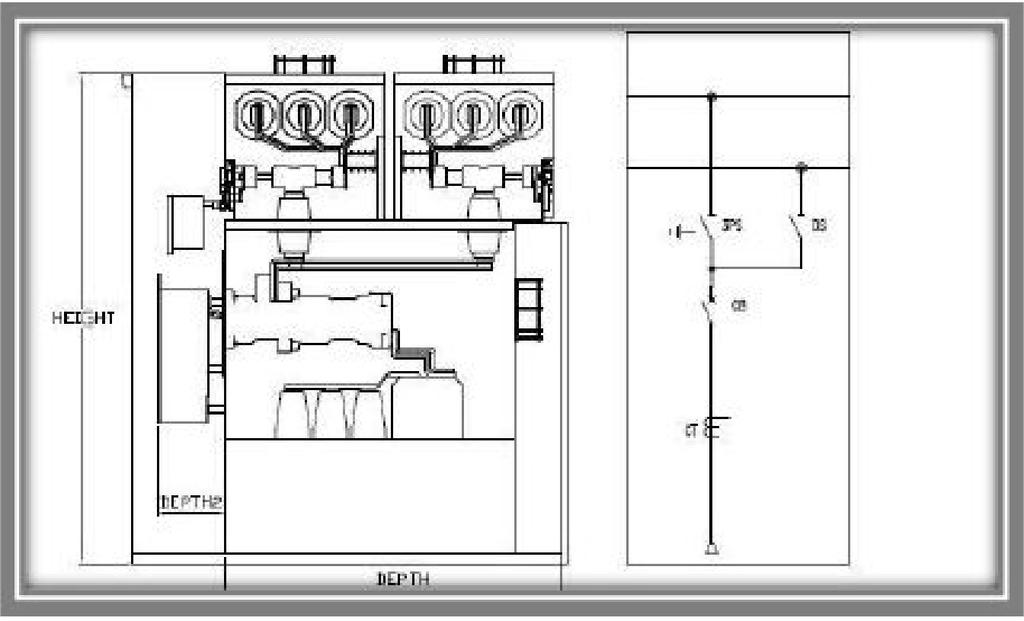
10 8 TYPICAL SECTION VIEWS Single Bus - Incoming Section Double Bus - Incoming Section Single Bus - Incoming Section with Line Side Disconnect Double Bus - Incoming Section with Line Side Disconnect Single Bus Bus Tie Double Bus Bus Coupler


11 9 Single Bus - Bus VT Double Bus - Bus VT Single Bus - Outgoing Section Double Bus - Outgoing Section Transfer Bypass Bus - Incoming Section Transfer Bypass Bus - Outgoing Section Powered by Safety
12 10 GUIDE SPECIFICATION 1.0 General 1.1 The intent of this specification is to have the manufacturer furnish the equipment and material specified herein complete and operable. 1.2 All standard accessories to the equipment specified shall be supplied even if not specifically mentioned in this specification. 1.3 Material used in the fabrication of the specified equipment shall be new, unused, and of the highest quality available. 2.0 Scope 2.1 Work Included Furnish gas insulated switchgear as detailed in these specifications. Any drawings or data sheets attached to the inquiry shall be considered part of this specification. The equipment shall be complete and operable Provide production tests and inspections as detailed in this specification To reasonably prevent the possibility of shipping damage, the manufacturer shall prepare the equipment for transportation to the jobsite and monitor the load out of this material It shall be the responsibility of the manufacturer to furnish all material, connections, splices, links, special tools, and information required to completely reassemble the switchgear in the field or to facilitate the installation of the switchgear when performed by an electrical contractor Guarantee the performance of the switchgear during a reasonable warranty period. This warranty shall, at a minimum, cover the equipment for eighteen (18) months from time of shipment or twelve (12) months from date of energization whichever occurs first Supply all drawings, documentation, and information as detailed. 2.2 Work Not Included Field installation of switchgear, unless otherwise specified Connection of incoming cables or bus Connection of outgoing branch feeder cables or bus Connection of external control cables or wiring Supply or installation of the required pressure relief duct system for the safe venting of gases generated during an internal arc fault. 3.0 Codes, Standards and Classifications The applicable codes and standards listed below should be considered as part of this specification. The latest revision in effect at time of inquiry shall apply for all standards referenced. 3.1 Switchgear IEC High-voltage switchgear and controlgear Part 1: Common specifications IEC High-voltage switchgear and controlgear Part 200: AC metal-enclosed switchgear and controlgear for rated voltages above 1kV and up to and including 52kV 3.2 Circuit Breaker IEC High-voltage switchgear and controlgear Part 100: High-voltage alternating current circuit breaker 3.3 Instrument Transformers IEC Instrument transformers Part 1: General requirements IEC Instrument transformers Part 2: Additional requirements for current transformers IEC Instrument transformers-part 3: Additional requirements for inductive voltage transformers 3.4 Disconnector and Earthing Switch IEC High-Voltage Switchgear and Controlgear Part 102: Alternating current disconnectors and earthing switches 3.5 Classifications to IEC Partition Class: PM Loss of Service Continuity Category LSC No classification due to gas-filled compartments LSC2B Cable termination compartments
13 11 GUIDE SPECIFICATION (cont.) Classification IAC BLFR 40kA, 1s with pressure relief duct and absorber or discharge into open air 3.6 It shall be the manufacturer s responsibility to be knowledgeable of these standards and codes. 4.0 Design Criteria 4.1 Rated Normal Currents The rated normal currents of components shall be valid for 40 C. 4.2 Temperature Limits and Environments Environmental conditions according to VDE and IEC Maximum Ambient Temperature 40 C Minimum Ambient Temperature -5 C (corresponds to minus 5 C indoor class) Maximum Relative Humidity 90% The equipment shall be suitable for installation and service at an altitude not exceeding 1000 meters above mean sea level. 5.0 Design Parameters 5.1 The equipment shall be designed for a rated maximum voltage of 36kV 5.2 The equipment shall have a nominal system voltage not to exceed 33kV 5.3 The equipment shall have a Rated Power Frequency Withstand Voltage of 80kV 5.4 The equipment shall have a Rated Lightning Impulse Withstand Voltage of 170kV 5.5 The equipment shall be rated for 50/60Hz 5.6 The main power bus bar current rating of 3150A or less. 5.7 The equipment shall have a rated short-time withstand current of 40kA for 3 seconds 5.8 The equipment shall have a rated peak withstand current of 104kA 5.9 The rated operating sequence shall be O-0.3s-CO- 3min-CO or O-0.3s-CO-15s-CO 5.10 The insulating gas shall be SF The Degree of Protection for the high-voltage live parts shall be IP The Degree of Protection for the low-voltage compartment shall be IP4X 5.13 The equipment shall be internal arc resistance accessibility Type BFLR and contain pressure relief ducts 6.0 Basic Construction 6.1 The switchgear shall be an indoor gas-insulated and metal-enclosed 3-phase design with segregated SF 6 insulated compartments for circuit breaker and bus bar systems. 6.2 The switchgear shall be designed to ensure optimum continuity, reliability of supply and safety of operation. 6.3 The high-voltage section shall consist of gas-tight stainless steel tanks built as a sealed pressure system. Each of these gas compartments shall have a filling valve, gas density monitoring pressure sensor and a pressure relief system. 6.4 The bus bar connections between each switchgear section will be non-bolted plug-in type. No gas filling shall be required for onsite assembly. 6.5 The power cables shall enter the bottom and connect by plug-in connectors. 6.6 The cable compartment shall have a pressure relief system leading to the pressure relief duct. 6.7 The switchgear gas compartment leakage rate shall be less than 0.1% per year. 6.8 All high-voltage parts with the exception of cable plugs will be located within SF 6 gas filled enclosure. 6.9 Operational safety and insulating properties shall be maintained as long as the SF 6 gas is at sea-level atmospheric pressure or greater The switchgear shall contain a passive protection system against internal arc faults in each partitioned compartment in order to maximize operator safety The passive safety section shall ensure that hot gases are guided via pressure relief disks from each SF 6 filled compartment. The pressure relief duct ends must be guided to a vented area for personnel safety Temperature-compensated sensors for pressure measurement shall continually monitor each gas compartment The high-voltage compartments shall be maintenance free for the lifetime of the equipment as long as operated within normal service conditions
14 12 GUIDE SPECIFICATION (cont.) 6.14 Compartments SF 6 Gas Compartments, each section shall have: Core module with built in vacuum circuit breaker and current transformers or sensors Bus bar modules with built in 2 or 3 position switches Air Compartments Cable termination compartment including provisions for conventional voltage transformer plug in connection Low voltage compartment including built in switch drives and secondary control components. It shall be a self-contained unit with an access door and incorporated into the switchgear section. All operating mechanisms will be motorized. Manual emergency operation and mechanical position indicators will be provided Bus Bars Main bus bars shall be high conductivity copper, uninsulated and silver plated at connection areas Ground bus bars shall be uninsulated, unplated copper Control and Secondary Wiring Control and Secondary Wiring Supplied Integral to the High Voltage, Bus Bar and Circuit Breaker Sealed Tanks DC control wiring shall be Type XHHW, Class 5 flexible conductor, 1.5mm AC control wire shall be Type XHHW, Class 5 flexible conductor, 2.5mm PT secondary wiring shall be Type XHHW, Class 5 flexible conductor, 4.0mm CT secondary wiring shall be Type XHHW, Class 5 flexible conductor, 4.0mm Ground wiring shall be Type XHHW, Class 5 flexible conductor, 6.0mm Interface Between Integral and External Secondary Wiring All integral control and secondary wiring shall be terminated on to terminal blocks, shorting type in the case of CT wiring Control and Secondary Wiring External to the Sealed Tanks Control wiring shall be SIS type #14 AWG, 41 strand extra flexible, stranded copper or larger Current transformer secondary wiring shall be SIS type #12 AWG, 65 strand, extra flexible, stranded copper or larger with braided metallic armor covering Current transformer secondary wiring shall terminate on shorting type terminal blocks All control wiring shall be UL listed and have a VW-1 flame retardant rating Exposed wiring shall be suitably protected against contact with sharp edges. Throughout the assembly it must be neatly bundled and secured with nylon wire ties. Where control wiring passes from cubicle to door it must be wrapped with suitable protection so as to prevent damage. Holes cut to allow control wires to pass from cubicle to cubicle will have a grommet for protection Splicing of control wire is not permitted. Control wiring must be a continuous length from terminal to terminal Each control wire shall be marked at both terminations to agree with wiring diagrams. Plastic wire markers of either the slip on or heat shrink variety shall be provided Control wires leaving the cubicle of origin must first terminate on a terminal block. No control wire may leave a cubicle directly from any other device Control wire tags shall follow Destination Method and must match the drawings Where possible, a minimum of 10% spare terminals shall be provided in each cubicle Meters, Switches, and Relays Indicating meters shall be three phase large digital display type visible 6 feet away from the front of the lineup and require minimum operator interface Control switches shall be rotary cam type with engraved face plates Ammeter and voltmeter transfer switches shall have an off position and shall be provided with knurled knob handles.
15 13 GUIDE SPECIFICATION (cont.) Selector type control switches (Auto-Manual or Hand-Off-Auto) shall have oval handles Protective relays shall be switchboard drawout type with removable dust tight viewing covers, front accessible connection plugs, built-in test capability, and mechanical targets that may be externally reset. Other electronic or multi-function relays may be specified for particular applications Current and voltage test switches for field monitoring and maintenance shall be provided when specified Indicating lights shall be provided as shown on the control schemes. Lamps shall be replaceable from the front of the switchgear without opening the cubicle door Nameplates Laminated plastic engraved nameplates shall be provided Identification nameplates shall be white with black letters, caution nameplates shall be yellow with black letters, and warning nameplates shall be red with white letters Each externally visible device or component shall have an identification nameplate. Lettering shall be, at a minimum, 5/32 inches in height Each internal device or component shall have an identification marking A single large permanent metal nameplate shall identify the sales order No, switchgear ratings and date and place of manufacture Finish All non stainless steel members shall be cleaned, rinsed and phosphatized prior to finishing Coating process shall be an electrostatically applied polyester powder with a final baked on average thickness between 1.5 and 2.0 mils Interior instrument compartments shall be White finish for enhanced visibility All internal parts shall be painted for corrosion protection, no bare parts allowed Standard exterior finish will be light gray. 7.0 Circuit Breakers 7.1 The circuit breakers shall be vacuum type and comply with IEC Publication The circuit breakers will be stationary mounted and type tested. Test certificates available after receipt of purchase order. 7.3 The high-voltage portion of the circuit breaker will be maintenance free for the lifetime of the equipment when operated within normal service conditions. 7.4 The circuit breaker drive mechanism shall be accessible for maintenance. 7.5 Each circuit breaker shall include: A stored-energy spring mechanism for motor charging and emergency manual operation Mechanical push buttons for closing and opening Mechanical indicators for switch position and circuit breaker operating mechanism position Circuit breaker operations counter Shunt release off Shunt release on Switch position wear-and-tear free proximity sensors. 8.0 Isolators and Earthing Switches 8.1 Isolators and earthing switches shall be motor operated with emergency manual operation capability. 8.2 The earthing position for all three phases must be visible through camera, laptop or monitor display located on the front door. 9.0 Instrument Transformers 9.1 Current transformers may be single or multi-ratio type with taps 9.2 Zero-sequence current transformers suitable for outdoor environments may be located below the switchgear assembly. 9.3 Voltage transformers shall be equipped with primary fuses and protected on the secondary side with molded case circuit breakers.
16 14 GUIDE SPECIFICATION (cont.) 10.0 Cable Compartment and Cable Terminations 10.1 The primary cable compartment shall contain cable sockets accessible for the connection of the power cables with the related cable termination plugs Power cables and terminations must be done in accordance DIN EN 50180/1 and be inner cone type sizes 2, 3 or 4 with a touch-proof system Interlocking 11.1 Limit position blocking of the switching devices Interdependence of the disconnector and earthing switch in the same section Interdependence of the disconnector and circuit breaker in the same section Interdependence of the circuit breaker and the earthing switch in the same section Dependence of the disconnector on the bus coupler circuit breaker and vice versa Accessories 12.1 Handle for disconnector mechanism Handle for earthing switch mechanism Hand crank for circuit breaker manual charge Padlockable pushbutton cover for disconnector, earthing switch and circuit breaker operating pushbuttons Inspection and Production Testing 13.1 Component bill of material shall be checked for proper quantity, description, and part number Physical dimensions shall be checked against approved drawings Equipment shall be subjected to a primary current injection procedure to determine proper operation of all current sensitive components Equipment shall be subjected to a primary voltage injection procedure to determine proper operation of all voltage sensitive components Complete assembly shall have a low frequency withstand (an AC high potential) test performed to assure insulation system integrity Each gas filled module shall have a gas tank integrity test Manufacturer shall have in place a system of recording, correcting, and verifying resolution of discrepancies discovered during the inspection and testing process Certified production test reports indicating satisfactory completion of all inspection procedures shall be available upon request Upon request the equipment shall be made available for customer inspection prior to shipment Test reports for design tests shall be available upon request Documentation 14.1 Drawings Prior to fabrication the following drawings shall be submitted by the manufacturer for approval Front elevation view Base plan including mounting details, cable entry area, and door swing requirements Cross section view of each different section Three line diagram Component bill of material indicating quantity, description, and part number Control or schematic diagram for each different unit Following the return of approval drawings the manufacturer shall prepare and submit wiring diagrams indicating physical location of secondary control components and the appropriate wiring connections. Each control wire will be labeled. Copies of these drawings shall be submitted to the customer, upon completion, for record After the return of approval drawings or after any change made to previously approved drawings, the manufacturer shall submit a record copy of any and all drawings that contained revisions After completion of the inspection and testing procedures the manufacturer shall submit a complete set of as built drawings. These drawings shall function
17 15 GUIDE SPECIFICATION (cont.) as a record of the final construction of the equipment at the time it left the factory Drawings may be provided in any of the following forms as requested by the customer: Full size plotted reproducible drawings size as required. D size measuring approximately 34 x 22, C size measuring approximately 22 x 17, B size measuring approximately 17 x 11, or A size measuring approximately 11 x 8½ Digital files in the latest version of Autodesk AutoCAD Digital file format may be dwf, pdf, dgn, or dwg as specified Each drawing prepared by manufacturer shall show, at a minimum, the name, jobsite location, purchase order or contract number, and equipment identification number in addition to any information required by manufacturer Operating and Maintenance Manuals At time of shipment the manufacturer shall provide a copy of the operating and maintenance instructions for all major components contained in the switchgear assembly Manuals shall contain a table of contents to allow for easy reference Operating and maintenance manual will be provided as pdf files on a CD for easy reference Spare Parts List Upon completion of the engineering phase, a quotation for one (1) year s recommended spare parts shall be submitted.


.1274.")
18 Contact Us Powell Electrical Systems, Inc Airport Blvd. Houston, Texas powellind.com Powell Canada Inc Range Road 263A Acheson, Alberta T7X 5A Powell (UK) Ltd. Ripley Road Bradford, West Yorkshire BD4 7EH +44.(0) Publication No Powell Industries, Inc.. all rights reserved. 06/2015 v4
NXPLUS C Single busbar. Maintenance-free for lifetime
 NXPLUS C Single busbar Maintenance-free for lifetime Energy Distribution Welcome! Page 2 Content Overview Technical data Typicals Panel design Circuit-Breaker panel Busbar Operation Metering Low-voltage
with Vacuum Circuit Breaker HAF
 M E T A L - C L A D S W I T C H G E A R Safety and Reliability with Vacuum Circuit Breaker HAF Flexible Design and Compact with Vacuum Circuit Breaker HVF Easy Installation and Maintenance We build a better
Gas Insulated Metal-clad Switchgear, HMGS!
 Medium Voltage HMGS-G10 HYUNDAI Medium Voltage Gas Insulated Metal-clad Switchgear, HMGS! SF6 Gas Insulated Metal-clad Switchgear is an integrated assembly of vacuum circuit breaker, 3-position switch,
TECHNICAL SPECIFICATION OF 11KV SF6 / VCB METAL ENCLOSED, INDOOR (PANEL TYPE) / OUTDOOR RING MAIN UNIT (RMU). (IEC standard equipment)
 / OUTDOOR RING MAIN UNIT (RMU). (IEC standard equipment)") TECHNICAL SPECIFICATION OF 11KV SF6 / VCB METAL ENCLOSED, INDOOR (PANEL TYPE) / OUTDOOR RING MAIN UNIT (RMU). (IEC standard equipment) 1 SCOPE OF SUPPLY This specification covers design, manufacture, shop
TECHNICAL SPECIFICATION OF 11KV SF6 / VCB METAL ENCLOSED, INDOOR (PANEL TYPE) / OUTDOOR RING MAIN UNIT (RMU). (IEC standard equipment) 1 SCOPE OF SUPPLY This specification covers design, manufacture, shop
AIR INSULATED EXTENDABLE SWITCHGEAR UP TO 12KV GUIDE
 AIR INSULATED EXTENDABLE SWITCHGEAR UP TO 12KV GUIDE Certificate Number FM35831 APPLICATION Typical Uses and Classification The MSGair switchgear is used in transformer and switching substations mainly
University of Houston Master Construction Specifications Insert Project Name
 SECTION 26 13 13 MEDIUM VOLTAGE SWITCHGEAR PART 1 - GENERAL 1.1 RELATED DOCUMENTS: A. The Conditions of the Contract and applicable requirements of Divisions 0 and 1 and Section 26 00 01, Electrical General
PIX-H Metal-clad switchgear up to 17.5kV
 AIR INSULATED SWITCHGEAR PIX-H Metal-clad switchgear up to 17.5kV for high rated applications Technical Specifications AREVA T&D Summary - Technical description... 3 - Standards... 6 - PIX in detail...
ZX2 Gas-insulated medium voltage switchgear
 Gas-insulated medium voltage switchgear Double busbar 13 8 10 12 11 10 9 8 7 2 1 3 4 5 6 2 Versatile Partitioned single or double busbar system for all applications even with the most demanding parameters
GE Consumer & Industrial Power Protection. New. SecoGear kV Metal-clad Switchgear. GE imagination at work
 GE Consumer & Industrial Power Protection New SecoGear 12-24kV GE imagination at work General SecoGear metal-clad switchgear is designed and manufactured with advance technology and has been comprehensively
SYSclad switchboard equipped with draw out type vacuum circuit breaker closed dooroperationoperation. SYSclad 12 17,5kV A.
 SYSclad switchboard equipped with draw out type vacuum circuit breaker closed dooroperationoperation 630 3150A SYSclad 12 17,5kV 16 31,5kA Generalities SYSclad is a medium voltage switchboard metal clad
ZX1.5-R. Gas-insulated medium voltage for railway application DISTRIBUTION SOLUTIONS. Gas-insulated medium voltage for railway application ZX1.
 DISTRIBUTION SOLUTIONS ZX1.5-R Gas-insulated medium voltage for railway application Safety and reliability 20% footprint saving Easy operation Complete solution ZX1.5-R Gas-insulated medium voltage for
CPG.1 Gas insulated, single busbar cubicle range Up to 27 kv / 2000 A / 31.5 ka Up to 38 kv / 2000 A / 31.5 ka IEEE Standards
 Medium Voltage Switchgear Primary Distribution CPG.1 Gas insulated, single busbar cubicle range Up to 27 kv / 2000 A / 31.5 ka General description Presentation Ormazabal s CPG System includes the CPG.1
Type SIMOPRIME A4, up to 24 kv, Air-Insulated Medium-Voltage Switchgear
 Circuit-Breaker www.siemens.com/energy Switchgear Type SIMOPRIME A4, up to 24 kv, Air-Insulated Medium-Voltage Switchgear s Technology Circuit-Breaker Switchgear Type SIMOPRIME, up to 17.5 kv, Air-Insulated
CPG.0 Single busbar gas-insulated cubicles
 MV Switchgear Primary Distribution CPG.0 Single busbar gas-insulated cubicles Up to 36 kv CPG System The quality of products designed, manufactured and installed by Ormazabal is underpinned by the implementation
Safe and Reliable. Flexible, Compact Design. Easy Installation and Maintenance
 M E T A L - C L A D S W I T C H G E A R Safe and Reliable Flexible, Compact Design Easy Installation and Maintenance We build a better future! Hyundai HMS medium-voltage metal-clad switchgears and control-gears,
ZX-Family Gas-insulated medium voltage switchgear
 ZX-Family Gas-insulated medium voltage switchgear Minimum overall costs ZX offers maximum economy The compact design of the panels reduces the space required and therefore the size of the station. Freedom
Our brand POWER DYNAMIC PASSION COMMITMENT CREATIVITY. A strong brand for strong products: 8PU Premium. MV Energy
 Our brand A strong brand for strong products: The ENERGOLINE brand represents our product portfolio of INDUSTRIAL SWITCHGEAR SYSTEMS. Our products are characterized by a high degree of safety, flexibility
MV Air Insulated Switchgear TAP17. Technical Data TGOOD
 MV Air Insulated Switchgear TAP17 Technical Data TGOOD 2017.1 Operating environmental conditions Place of installation: Indoor or outdoor Ambient temperature: 25 ~ +40 (higher or lower temperature optional)
SUBSTATION VACUUM CIRCUIT BREAKER (38KV)
") SUBSTATION VACUUM CIRCUIT BREAKER (38KV) For more than four decades, Myers Power Products has led the switchgear market in quality for the electric industry, delivering highly reliable products for utilities
SUBSTATION VACUUM CIRCUIT BREAKER (38KV) For more than four decades, Myers Power Products has led the switchgear market in quality for the electric industry, delivering highly reliable products for utilities
SUBSTATION VACUUM CIRCUIT BREAKER (25.8 / 27KV)
") SUBSTATION VACUUM CIRCUIT BREAKER (25.8 / 27KV) For more than four decades, Myers Power Products has led the switchgear market in quality for the electric industry, delivering highly reliable products
SUBSTATION VACUUM CIRCUIT BREAKER (25.8 / 27KV) For more than four decades, Myers Power Products has led the switchgear market in quality for the electric industry, delivering highly reliable products
SUBSTATION VACUUM CIRCUIT BREAKER (15.5KV)
") SUBSTATION VACUUM CIRCUIT BREAKER (15.5KV) For more than four decades, Myers Power Products has led the switchgear market in quality for the electric industry, delivering highly reliable products for utilities
SUBSTATION VACUUM CIRCUIT BREAKER (15.5KV) For more than four decades, Myers Power Products has led the switchgear market in quality for the electric industry, delivering highly reliable products for utilities
8DJ. Maintenance-free for lifetime
 8DJ Maintenance-free for lifetime Energy Distribution Welcome! Page 2 October 1 st 2008 8DJ Main Applications for Medium-Voltage Switchgear Power generation Power stations G Power transmission High and
Product Specification Guide. Title: Southern States 362 kv RLSwitcher Vertical Interrupter Style Reactor Switcher
 TABLE OF CONTENTS PAGE 1.0 SCOPE... 2 2.0 STANDARDS... 2 3.0 DESIGN REQUIREMENTS... 2 3.01 Service Conditions... 2 3.02 Ratings... 2 3.03 Interrupter... 3 3.04 SF6 Gas System... 4 3.05 Terminal Pads...
Switchgear Type SIMOSEC, up to 24 kv, Air-Insulated, Extendable
 www.siemens.com/medium-voltage-switchgear Switchgear Type SIMOSEC, up to 24 kv, Air-Insulated, Extendable Medium-Voltage Switchgear Catalog HA 41.43 2012 Answers for infrastructure and cities. Neue Bilder
Circuit-Breaker Switchgear Type SIMOPRIME, up to 17.5 kv, Air-Insulated Medium-Voltage Switchgear.
 Circuit-Breaker Switchgear Type SIMOPRIME, up to 17.5 kv, Air-Insulated Medium-Voltage Switchgear www.siemens.com/energy Technology s Contents Application Page Benefits 2 Typical uses 2 and 3 Technical
B kv T&D GAS INSULATED SWITCHGEAR
 GAS INSULATED SWITCHGEAR B 105 170 300 kv The increasing demand for electrical power in cities and industrial centers necessitates the installation of a compact and efficient distribution and transmission
ZX2.2 Gas-insulated medium voltage switchgear
 ZX2.2 Gas-insulated medium voltage switchgear 2 Brochure ZX2.2 Power engineering from ABB Solutions for the future As a technology group with global operations, ABB supplies the solutions of the future
Publication No.: PSG
 TABLE OF CONTENTS PAGE 1.0 SCOPE...2 2.0 STANDARDS...2 3.0 DESIGN REQUIREMENTS...2 3.01 Service Conditions... 2 3.02 Ratings... 3 3.03 Resistors... 3 3.04 Interrupter... 4 3.05 SF 6 Gas System... 4 3.06
DISTRIBUTION SOLUTIONS. GSec Gas-insulated switching and isolating apparatus
 DISTRIBUTION SOLUTIONS GSec Gas-insulated switching and isolating apparatus GSec is a three-position SF6 gas-insulated switchdisconnector designed for use in medium voltage switchgear for secondary distribution
UniGear. Technical Guide
 UniGear Technical Guide CONTENTS 0 CONTENTS 1.1 Compartments 1/2 1.2 Components of the structure 1/3 1.2.1 Hot-galvanized steel sheet 1/3 1.2.2 Painted steel sheet 1/4 1.2.3 Copper 1/5 1.2.4 Insulating
Metal Clad Air Insulated Switchgear
 Metal Clad Air Insulated Switchgear 1/ SecoGear Metal Clad Switchgear Features Fully metal-clad Equipped with Embedded pole VCB Full Front access (can be installed against wall) Perfect interlocking system
MESG 12 / 17.5 / 24 / 36 KV
 MESG 12 / 17.5 / 24 / 36 KV Medium Voltage Air Insulated Metal Enclosed Switchgear up to 36 kv- up to 1250 A - up to 25 ka for 1 sec. with SF6 or vacuum circuit breakers. 750 METAL ENCLOSED 1 1 ) GENERAL
SION Vacuum Circuit-Breakers. Answers for energy. Medium-Voltage Equipment Selection and Ordering Data. Catalog HG
 Medium-Voltage Equipment Selection and Ordering Data Catalog HG 11.0 008 Answers for energy. R-HG11-17.tif Siemens HG 11.0 008 Contents Contents Page SION Vacuum Circuit-Breakers Description General Construction
GE Industrial Solutions. User/Installation Manual for 4.76kV -15kV SecoBloc
 GE Industrial Solutions User/Installation Manual for 4.76kV -15kV SecoBloc Index General Scope...3 Standards...3 Operating conditions...3 Technical specification...3 Basic structure Features...4 Operation...4
MEDIUM VOLTAGE CE-B36 METAL CLAD SWITCHBOARDS. CE - B36 - C - en - REV
 CE - B36 - C - en - REV.00 2011.9 EDIU VOLTAGE EDIU VOLTAGE APPLICATION CE-B etal Clad switchboards are designed for use in public and industrial distribution system up to 36kV for the operation and protection
Benefits, typical uses
 R-HA26-013. eps Switchgear Type 8BT1, up to 24kV,Air-Insulated Contents Application Page Application Benefits 2 Typical uses 2 and 3 Technical Data Ratings 4 Classification, dimensions, 5 room planning
MEDIUM VOLTAGE CE-B METAL CLAD SWITCHBOARDS. CE-B-C-en-REV
 CE--C-en-REV.04 2016.1 MEDIUM VOLTAGE MEDIUM VOLTAGE APPLICATION CE- Metal Clad switchboards family are designed for use in public and industrial distribution system up to 40,5kV for the operation and
Catalog HA Edition up to 24 kv, Air-Insulated, Extendable. Medium-Voltage Switchgear. siemens.com/simosec
 Catalog HA 41.43 Edition 2018 Switchgear Type SIMOSEC, up to 24 kv, Air-Insulated, Extendable Medium-Voltage Switchgear siemens.com/simosec Application Typical uses R-HA41-135.tif R-HA40-112.tif R-HA41-115.tif
Typical Specification
 Engineered to Order Built to Last Typical Specification VAULT VRPFI, TWO POSITION, ROTARY PUFFER SWITCHGEAR PART 1- GENERAL 1.1 DESCRIPTION A. The switch shall consist of manually operated load interrupting,
Switchgear Type 8BT1, up to 24 kv, air-insulated. Medium Voltage Switchgear Catalog HA 26.
 www.siemens.com/medium-voltage-switchgear Switchgear Type 8BT1, up to 24 kv, air-insulated Medium Voltage Switchgear Catalog HA 26.31 2012 Answers for infrastructure and cities. R-HA26-013. eps Contents
Submersible Vacuum Fault Interrupters
 Submersible Vacuum Fault Interrupters UG Distribution Medium Voltage Vacuum Fault Interrupters Functional Specification Guide PS024002EN Functional Specification for 2.4kV to 17.5kV UG Distribution Medium
EMC 24 SERIES METAL CLAD SWITCHGEAR. We engineer, we assure. Up to 24 kv - 25 ka With Withdrawable, Air-Insulated, Medium Voltage Distribution Panel
 We engineer, we assure. EMC 24 SERIES METAL CLAD SWITCHGEAR Up to 24 kv - 25 ka With Withdrawable, Air-Insulated, Medium Voltage Distribution Panel Saudi Cable Company REF: EMC24-EN-16-04 2 www.elimsan.com
SafeLink The Ultimate RMU. Rex de Bruyn PTMV New Zealand. ABB Ltd - Page 1 ABB
 Rex de Bruyn PTMV New Zealand SafeLink The Ultimate RMU Ltd - Page 1 TheSafe Range of Ring Main Switchgear SafeLink : 12kV Compact Fuse Technology SafeRing : 12-24kV Fuse & Circuit Breaker Technology SafePlus
Section SWITCHBOARDS. Introduction. Part 1 - General. Related Work
 Section 16435 - SWITCHBOARDS Introduction Part 1 - General Related Work Section 16070 Seismic Anchorage and Restraint Section 16075 Electrical Identification Section 16080 Power Distribution Acceptance
COMPACT AND EXTENSIBLE RING MAIN UNIT. insulated Ring Main Unit with load break switch or integrated vacuum circuit breaker
 DR-6/DT-6 COMPACT AND EXTENSIBLE RING MAIN UNIT BUILT TO LAST! DR-6/DT-6 Compact and/or extensible SF 6 insulated Ring Main Unit with load break switch or integrated vacuum circuit breaker SAFETY, RELIABILITY,
Product Specification Guide. Title: Southern States 72 kv RLSwitcher Vertical Interrupter Style Reactor Switcher
 TABLE OF CONTENTS PAGE 1.0 SCOPE... 2 2.0 STANDARDS... 2 3.0 DESIGN REQUIREMENTS... 2 3.01 Service Conditions... 2 3.02 Ratings... 3 3.03 Interrupter... 3 3.04 SF6 Gas System... 4 3.05 Terminal Pads...
with Vacuum Circuit Breaker HAF
 M E T A L - C L A D S W I T C H G E A R Safety and Reliability with Vacuum Circuit Breaker HAF Flexible Design and Compact with Vacuum Circuit Breaker HVF Easy Installation and Maintenance We build a better
2018 Consultant s Handbook Division 26 Electrical 2413 Switchboards
 1 General 1.1 Switchboards shall be U.L. listed and labeled. 1.2 Each switchboard shall have its own main disconnecting means unless it is located in the same room as its source of origin. In most cases
All rights reserved. Neither this catalogue nor any part of it may be copied using any method or for any purposes. Most studies are legally protected.
 Issued: January 2013 Copyright by ZPUE Katowice S.A. All rights reserved. Neither this catalogue nor any part of it may be copied using any method or for any purposes. Most studies are legally protected.
BHARAT HEAVY ELECTRICALS LIMITED, JHANSI
 BHARAT HEAVY ELECTRICALS LIMITED, JHANSI DESIGN, MANUFACTURING, TESTING, SUPPLY INSTALLATION AND COMMISSIONING OF 11KV VACUUM CIRCUIT BREAKER NOTE : 1 VENDOR must submit complete information against clause
DESIGN GUIDELINES LOW VOLTAGE SWITCHGEAR PAGE 1 of 5
 DESIGN GUIDELINES LOW VOLTAGE SWITCHGEAR PAGE 1 of 5 1.1. APPLICABLE PUBLICATIONS 1.1.1. Publications listed below (including amendments, addenda, revisions, supplements, and errata), form a part of this
Michigan State University Construction Standards SECONDARY UNIT SUBSTATIONS PAGE
 PAGE 261116-1 SECTION 261116 PART 1 - GENERAL 1.1 RELATED DOCUMENTS A. Drawings and general provisions of the Contract, including General and Supplementary Conditions and Division 01 Specification Sections,
36kV Gas Insulated Medium Voltage Switchgear
 GE Industrial Solutions 36kV Gas Insulated Medium Voltage Switchgear User Manual Safety first! Important recommendations: Switchgear should be installed in a clean, dry, ventilated room suitable for electrical
Medium Voltage Metal-Enclosed Switches
 Medium Voltage Metal-Enclosed Switches Outdoor Medium Voltage Switch.1 Medium Voltage Switch MVS Product Description............................................. 2 Application Description..........................................
MEDIUM VOLTAGE AIR INSULATED ARC-RESISTANT LOAD BREAK AND DISCONNECT SWITCHES
 MEDIUM VOLTAGE AIR INSULATED ARC-RESISTANT LOAD BREAK AND DISCONNECT SWITCHES Description JRS arc-resistant fused/non-fused load break and fused/non-fused disconnect switches are available for applications
MEDIUM VOLTAGE CE-B METAL CLAD SWITCHBOARDS. CE - B - C - en - REV
 MEDIUM VOLTAGE MEDIUM VOLTAGE APPLICATION CE-B Metal Clad switchboards are designed for use in public and industrial distribution system up to 24kV for the operation and protection of lines, generators,
the safe, reliable, and efficient choice for MV switchgear
 Power Xpert UX IEC Medium Voltage switchgear Tested to IEC 62271-200 17.5 kv up to 50 ka - 3 s 24 k V up to 25 ka - 3 s Air insulated switchgear Internal arc classified LSC2B-PM UX the safe, reliable,
SECTION PANELBOARDS
 SECTION 16470 PANELBOARDS PART 1 - GENERAL 1.1 RELATED DOCUMENTS A. The general provisions of the contract including General and Special Conditions and General Requirements shall apply to all work under
AIR INSULATED METAL ENCLOSED SWITCHGEAR AND CONTROLGEAR
 AIR INSULATED METAL ENCLOSED SWITCHGEAR AND CONTROLGEAR ANGLER SWITCHING DEVICES CONTENTS 1. General 2. Switchgear Types - Switch Disconnector - Disconnector 3. Cubicle Types - Cubicle with Switch Disconnector
Medium Voltage Metal-Enclosed Switches
 Medium Voltage Metal-Enclosed Switches Outdoor Medium Voltage Switch.1 Introduction Product Selection Guide....................................2 Medium Voltage Switch MVS Product Description......................................
Medium voltage products UniSec DY800 New 24 kv air-insulated medium voltage switchgear to e-distribuzione specifications
 Medium voltage products UniSec Y800 New 24 kv air-insulated medium voltage switchgear to e-istribuzione specifications UniSec Y800 ubicles available Unit e-istribuzione specifications (Ed. 4) UniSec IS/1
33KV INDOOR SWITCHGEAR
 33KV INDOOR SWITCHGEAR September 2017 Engineering Department WEST BENGAL STATE ELECTRICITY TRANSMISSION COMPANY LIMITED Regd. Office: VidyutBhawan, Block DJ, Sector-II, Bidhannagar, Kolkata 700091. CIN:
General. Main electric circuits Fuses compartment Operating mechanisms Cables connection compartment
 General The switchgear must be suitable for 36 kv rated voltage and specifically conceived for the secondary distribution substations in M.V. with either ring or radial type networks. The switchgear must
This small footprint makes a BIG impact
 Power Xpert XGIS Gas-insulated medium voltage switchgear This small footprint makes a BIG impact Saving space is just one benefit of our gas-insulated switchgear. Big where it matters, small where it counts.
Unified requirements for systems with voltages above 1 kv up to 15 kv
 (1991) (Rev.1 May 2001) (Rev.2 July 2003) (Rev.3 Feb 2015) (Corr.1 June 2018) Unified requirements for systems with voltages above 1 kv up to 15 kv 1. General 1.1 Field of application The following requirements
SF 6 Gas Insulated Switchgear Type SDH314 / SDHa314 for 72.5 to 145 kv
 Three Phase Encapsulated Type SF 6 Gas Insulated Switchgear Type SDH314 / SDHa314 for 72.5 to 145 kv 06B1-E-0002 Small Space Requirement, High Reliability and Safety ー 72.5 to 145 kv GIS, SDH314/SDHa314
Switchgear Type SIMOSEC, up to 24 kv, Air-Insulated, Extendable
 Switchgear Type SIMOSEC, up to 24 kv, Air-Insulated, Extendable Medium-Voltage Switchgear Totally Integrated Power SIMOSEC Catalog HA 41.43 Edition Sept. 2014 Answers for infrastructure and cities. Neue
Power Xpert UX 36 High-voltage switchgear system. Reliable and safe for high performance applications
 Power Xpert UX 36 High-voltage switchgear system Reliable and safe for high performance applications A high-performance solution for high-voltage power distribution Eaton s Power Xpert UX 36 IEC high-voltage
UP TO 17,5 kv LSC 2B PM (METAL-CLAD) WITHDRAWABLE VACUUM CIRCUIT BREAKER MEDIUM VOLTAGE CUBICLES
 WITHDRAWABLE VACUUM CIRCUIT BREAKER MEDIUM VOLTAGE CUBICLES") UP TO 17,5 kv LSC 2B PM (METAL-CLAD) WITHDRAWABLE VACUUM CIRCUIT BREAKER MEDIUM VOLTAGE CUBICLES 1 TABLE OF CONTENTS 1. SCOPE 2. GENERAL 2.1 STANDARDS AND REGULATIONS 2.2 OPERATING CONDITIONS 2.3 DOCUMENTATION
UP TO 17,5 kv LSC 2B PM (METAL-CLAD) WITHDRAWABLE VACUUM CIRCUIT BREAKER MEDIUM VOLTAGE CUBICLES 1 TABLE OF CONTENTS 1. SCOPE 2. GENERAL 2.1 STANDARDS AND REGULATIONS 2.2 OPERATING CONDITIONS 2.3 DOCUMENTATION
Medium Voltage Standby non-paralleling Control GUIDE FORM SPECIFICATION
 Medium Voltage Standby non-paralleling Control 1. GENERAL GUIDE FORM SPECIFICATION A. The requirements of the contract, Division 1, and part 16 apply to work in this section. 1.01 SECTIONS INCLUDE A. Medium
voltage switchgear ZX ABB ZX Family 1
 Gas-insulated medium voltage switchgear ZX ABB ZX Family 1 ZX family general presentation Agenda Medium Voltage Switchgear Definition and application ABB Calor Emag in Ratingen Location, experience and
VOLUME: IIIC SCHEDULE IIIC/4 11 KV AND 3.3 KV SWITCHGEARS
 VOLUME: IIIC SCHEDULE IIIC/4 11 KV AND 3.3 KV SWITCHGEARS A. 11 KV SWITCHGEAR 1.0 SWITCHGEAR ASSEMBLY 1.1 Make : 1.2 Type : 1.3 Reference Standard : 1.4 Voltage (Nom./Max.) KV : 1.5 Phase, Frequency No,Hz.
A. Submit manufacturer's literature and technical data before starting work.
 SECTION 16425 SWITCHBOARD PART 1 GENERAL 1.01 SUMMARY A. Related Section: 1. 16450 - Grounding. 1.02 SUBMITTALS A. Submit manufacturer's literature and technical data before starting work. B. Submit Shop
020: 2013 CEB SPECIFICATION MINIATURE CIRCUIT BREAKER (MCB)
") 020: 2013 CEB SPECIFICATION MINIATURE CIRCUIT BREAKER (MCB) CEYLON ELECTRICITY BOARD SRI LANKA Telephone: +94 11 232 0953 Fax: +94 11 232 3935 CONTENTS Page 1.0 Scope 3 2.0 System Parameters 3 3.0 Service
020: 2013 CEB SPECIFICATION MINIATURE CIRCUIT BREAKER (MCB) CEYLON ELECTRICITY BOARD SRI LANKA Telephone: +94 11 232 0953 Fax: +94 11 232 3935 CONTENTS Page 1.0 Scope 3 2.0 System Parameters 3 3.0 Service
SafeGear Motor Control Center Arc Resistant Metal-Clad Construction Brochure
 2017 SafeGear Motor Control Center Arc Resistant Metal-Clad Construction Brochure SafeGear Motor Control Center Arc resistant Metal-Clad construction Brochure Table of Contents 1. Description 1 1 2. SafeGear
5kV to 38kV, 630 Amp to 4000 Amp Indoor or Outdoor Application
 The most advanced Arc-Resistant Switchgear, designed and built to provide maximum safety in the event of an Internal Arcing Fault. 5kV to 38kV, 630 Amp to 4000 Amp Indoor or Outdoor Application Page 1
ME Switchgear with Vacuum Circuit Breaker and Auto-jet II Switch with Ground Position
 LET S BE PACIFIC November 0 Volume Number 5 ME Switchgear with Vacuum Circuit Breaker and Auto-jet II Switch with Ground Position Federal Pacific has the capability to engineer, fabricate and assemble
Underground Distribution Switchgear
 Underground Distribution Switchgear Functional Specification Guide Functional Specification for 15 kv, 25 kv, or 35 kv Underground Distribution Switchgear 1. Scope 1.1. This specification applies to three-phase,
SION Vacuum Circuit-Breakers. Answers for energy. Medium-Voltage Equipment Selection and Ordering Data. Catalog HG
 Medium-Voltage Equipment Selection and Ordering Data Catalog HG 11.02 2011 Answers for energy. R-HG11-172.tif 2 Siemens HG 11.02 2011 Contents SION Vacuum Circuit-Breakers Medium-Voltage Equipment Catalog
OVERVIEW DESCRIPTION AND CHARACTERISTICS APPARATUS AND TYPES AVAILABLE SWITCHGEAR CHARACTERISTICS INSTRUMENT TRANSFORMERS MEASUREMENT SENSORS
 OVERVIEW DESCRIPTION AND CHARACTERISTICS APPARATUS AND TYPES AVAILABLE SWITCHGEAR CHARACTERISTICS INSTRUMENT TRANSFORMERS MEASUREMENT SENSORS PROTECTION AGAINST INTERNAL ARCS TYPICAL UNITS 3 Characteristics
Fixed-Mounted Circuit-Breaker Switchgear Type 8DA and 8DB up to 40.5 kv, Gas-Insulated
 www.siemens.com/medium-voltage-switchgear Fixed-Mounted Circuit-Breaker Switchgear Type 8D and 8DB up to 0.5 kv, Gas-Insulated Medium-Voltage Switchgear Catalog H 35.11 201 nswers for infrastructure and
CONTENT. EPE METALCLAD SWITCHGEARS AMS SERIES 12kV AMS METALCLAD SWITCHGEAR 24kV AMS METALCLAD SWITCHGEAR 40.5KV AMS METALCLAD SWITCHGEAR
 CONTENT EPE METLCLD SWITCHGERS SERIES EPE 1220 / - 12KV METLCLD SWITCHGER EPE 10D - 12KV METLCLD SWITCHGER EPE 24-24KV METLCLD SWITCHGER EPE 36-36KV METLCLD SWITCHGER EPE METLCLD SWITCHGERS MS SERIES 12
Gas-Insulated Switchgear. Type 8VN1 blue GIS up to 145 kv, 40 ka, 3150 A
 Gas-Insulated Switchgear Type 8VN1 blue GIS up to 145 kv, 40 ka, 3150 A siemens.com/energy-management Table of content Gas-insulated switchgear Product portfolio 72.5 550 kv Vacuum interrupters for switching
ATLV MaxSG. Low Voltage Metal Enclosed Switchgear
 ATLV MaxSG Low Voltage Metal Enclosed Switchgear ABB, INC. Product General Description MaxSG Switchgear ABB MaxSG switchgear is a further continuation in the development of innovative products from ABB,
SF 6 Gas Insulated Switchgear Type SDH714 for 72.5 to 145 kv
 Three-phase Encapsulated Type SF 6 Gas Insulated Switchgear Type SDH714 for 72.5 to 145 kv 06B1-E-0020 Small Space Requirement, High Reliability and Safety ー 72.5 to 145kV GIS, SDH714 The number of application
A system fault contribution of 750 mva shall be used when determining the required interrupting rating for unit substation equipment.
 General Unit substations shall be 500 kva minimum, 1500 kva maximum unless approved otherwise by the University. For the required configuration of University substations see Standard Electrical Detail
Air-insulated switchgear UniGear type ZS1
 Air-insulated switchgear UniGear type ZS1 ABB Power Technologies / 1-7074 D 12-03-2003 - Air-insulated switchgear UniGear type ZS1 ABB Power Technologies / 2-7075 D 1 2-03-2003 - Rated voltage kv 12 17.5
GMA. Medium-voltage switchgear
 Medium-voltage switchgear Gas-insulated switchgear up to 24 kv - 2500 A - 31.5 ka Earthing without automatically CLOSE / OPEN of the Circuit Breaker Operation - Maintenance Technical Manual No. AGS 531
B kv Gas-insulated Substations
 72.5 145 kv Gas-insulated Substations The increasing demand for electrical power in cities and industrial centres requires the installation of a compact and efficient distribution and transmission network.
>> WI. up to 52 kv. Gas-Insulated Switchgear with Vacuum Circuit-Breaker 1, 2 or 3-phase. System configuration AREVA T&D
 GAS-INSULATED SWITCHGEAR UNITS >> WI up to 52 Gas-Insulated Switchgear with Vacuum Circuit-Breaker 1, 2 or 3-phase System configuration AREVA T&D Conditions of Delivery The General Conditions of Delivery
A. This Section includes Low Voltage Switchgear Work, as indicated on the drawings, and as specified herein.
 16425 SWITCHBOARD ************************************************************************************************************* SPECIFIER: CSI MasterFormat 2004 number: 26 24 13 An optional keynote to
AF series contactors (9 2650)
") R E32527 R E39322 contactors General purpose and motor applications AF series contactors (9 2650) 3- & 4-pole contactors General purpose up to 2700 A Motor applications up to 50 hp, 900 kw NEMA Sizes 00
R E32527 R E39322 contactors General purpose and motor applications AF series contactors (9 2650) 3- & 4-pole contactors General purpose up to 2700 A Motor applications up to 50 hp, 900 kw NEMA Sizes 00
SECTION ENCLOSED SWITCHES AND CIRCUIT BREAKERS
 SECTION 26 28 16 ENCLOSED SWITCHES AND PART 1 - GENERAL 1.1 SUMMARY A. Section includes the following individually mounted, enclosed switches and circuit breakers rated 600V AC and less: 1. Fusible switches.
Outdoor live tank vacuum circuit breaker Type OVB-VBF for 24/36/40.5 kv applications
 Outdoor live tank vacuum circuit breaker Type OVB-VBF for 24/36/40.5 kv applications ABB a global leader ABB is a global leader in power and automation technologies that enable utility and industry customers
Low Voltage Switchgear Type WL Low Voltage Metal-Enclosed Switchgear
 13 Low Voltage Switchgear Siemens Type WL low voltage metal-enclosed switchgear is designed, constructed and tested to provide superior power distribution, power monitoring and control. At the heart of
CITY OF LOMPOC UTILITIES DEPARTMENT ELECTRICAL DIVISION SPECIFICATION NO. ELE-112 SUBSTATION CLASS VACUUM CIRCUIT BREAKERS OCTOBER 2008
 CITY OF LOMPOC UTILITIES DEPARTMENT ELECTRICAL DIVISION SPECIFICATION NO. ELE-112 SUBSTATION CLASS VACUUM CIRCUIT BREAKERS OCTOBER 2008 SPECIFICATION NO: ELE_112_R1.doc Page 1 of 3 Rev. 10/28/2008 SPECIFICATION
Switchgear Type 8DJH for Secondary Distribution Systems up to 24 kv, Gas-Insulated
 Catalog HA 40.2 Edition 2017 Switchgear Type 8DJH for Secondary Distribution Systems up to 24 kv, Gas-Insulated Medium-Voltage Switchgear siemens.com/8djh Application Typical uses R-HA40-111.tif R-HA40-112.tif
Switchgear Type 8DJH 36 for Secondary
 Catalog HA 40.3 Edition 2017 Switchgear Type 8DJH 36 for Secondary Distribution Systems up to 36 kv, Gas-Insulated Medium-Voltage Switchgear siemens.com/8djh36 Application Typical uses R-HA40-135.tif R_HA40-150a
ACCESSORIES FOR LPOF, HPPT AND XLPE HIGH VOLTAGE CABLE SYSTEMS PRODUCT CATALOGUE
 ACCESSORIES FOR LPOF, HPPT AND XLPE HIGH VOLTAGE CABLE SYSTEMS PRODUCT CATALOGUE hvgrid-tech designs and manufactures high voltage cable accessories for all types of cable systems, ranging from 69 kv to
TGI Vacuum Circuit-Breaker Air isolator Earthing switch
 TGI Vacuum Circuit-Breaker Air isolator Earthing switch PATENT Versatile Visible isolation Simple Removable Index 3 in 1 2 Simple and versatile 4 Operations sequence ON Commissioning 8 Operations sequence