IYJM Rev E. SafeLink Manual. 12kV SF 6 Insulated Ring Main Unit Installation and Operating Instructions. Copyright 2009 ABB, All rights reserved
|
|
|
- Nigel Booker
- 6 years ago
- Views:
Transcription


1 IYJM Rev E SafeLink Manual 12kV SF 6 Insulated Ring Main Unit Installation and Operating Instructions Copyright 2009 ABB, All rights reserved
2 1YJM Rev E 2 / 33 Product Overview ABB's type-tested SafeLink ring main unit (RMU) is an SF 6 insulated RMU utilising the latest developments in switchgear technology to provide a very compact switchgear solution. SafeLink is a completely sealed system with a stainless steel tank containing all live parts and switching functions. A hermetically sealed tank separated from the outside environment ensures a high level of reliability as well as personal safety and a virtually maintenance free system. SafeLink is manufactured according to the latest environmental and quality standards. The ABB assembly plant is certified according to ISO9001 (Quality) and ISO14001 (Environmental). SafeLink equipment conforms to all applicable IEC standards. This manual provides detailed information on the handling, installation, commissioning and operation of SafeLink. The range of SafeLink products and the specifications of the equipment are subject to change without notice as product features and benefits are added. For further information, or to discuss SafeLink operation, please contact your local ABB office or the ABB factory in New Zealand: ABB Limited Power Products Medium Voltage PO Box Edmonton, Auckland New Zealand Tel: Fax: Web:
3 1YJM Rev E 3 / 33 Table of contents Product Overview General Description SafeLink Features CFC, CCC, DF, DC CFCC, CCCC, CFCD CFCF Outdoor Enclosure Technical Data Operating Conditions Electrical Data Rating Label Standards Compliance Transport & Handling Storage Transporting Shock Monitored Shipment Instruction for Switchgear: Instructions for Customer Inward Goods Personnel: Dimensions & Weights Installation Foundations Main Cable Boxes Cable Connection Outdoor Enclosure Operation Gas Density Gauge General Switch Operation Fuse Types and Replacement Fuse Tables Cable Box Interlock Cable Testing Voltage and phase balance test Maintenance Environmental SF 6 Gas Maintenance Gas Filling Environmental Certification Life Expectancy of Product Recycling Capability End-Of-Life Accessories Fault Passage Indicators Remote LED indicator Voltage Indicator Phase Comparator Auxiliary Switch Motor Operator Gas Density Monitor... 30
4 1YJM Rev E 4 / Shunt Trip Cable Clamp Rail Bottom Cover/Gland Plates Manual Trip Gas Filling/Sampling Adaptor Kit Extended Height Plinth TB-A 12 Kabeldon Termination Boot Lifting Frame... 32
5 1YJM Rev E 5 / 33 1 General Description This manual provides details needed to install and operate the SafeLink ring main unit. The SafeLink unit is certified for use on distribution systems operating at up to 12kV. SafeLink is available in several configurations based on ring and fuse-protected switches: e.g. CFC, CCC, CFCC, and CFCF; where C denotes a load break switch and F a switch-fuse combination. The switch-fuse combination has three-phase tripping and when the switch is earthed, both ends of the fuses are connected to earth. SafeLink units can be supplied with direct busbar connections (D) in place of load break switches to allow SafeLink units to be joined with an external cable connection. For example, units configured as CFCD and DFC, when joined, will give three ring switches and two switch-fuse combinations. Each switch is in the form of a three-position switch giving on, off and earthed conditions with respect to the connected cable. The status of each switch is indicated by the symbol visible in the round hole towards the top of the mimic panel and confirmed by the mimic diagram. Active flags in the diagram match the circuit condition with black confirming open switches and white indicating switches that are closed. Access to the cable box and fuse compartment is interlocked with the switch status. The operating handle is designed to give a delay between switching operations. Insertion of the operating handle is controlled by a rotary selector, which has one of three possible states: 1. Handle access blocked. 2. Switching between off and on and switch-fuse reset possible. 3. Switching between off and earth possible. The selector handle can be padlocked in any of these three positions.

 2 Lift up lid 3 Gas density")


6 1YJM Rev E 6 / SafeLink Features Item No. Description 1 Short circuit indicator (optional) 2 Lift up lid 3 Gas density indicator 4 Fuse blown indicator 5 Switch position symbol 6 Switch handle socket 7 Switch mode selector (on/off, blocked, off/earth) 8 Capacitive voltage indicator 9 Padlocking device 10 Interlocked cable compartment door 11 Interlocked fuse access door catch 12 Fuses contained behind door 13 Rating plate, serial number 14 Lifting lugs 15 Cable-door handle bracket includes door padlock facility
7 1YJM Rev E 7 / CFC, CCC, DF, DC Left Hand View (end panel removed) Front View Single line diagrams Foundation View (Section AA) CFC Mass: 300 kg
8 1YJM Rev E 8 / CFCC, CCCC, CFCD Left Hand View (end panel removed) Front View Single line diagrams Foundation View (Section AA) CFCC Mass: 320 kg
9 1YJM Rev E 9 / CFCF Left Hand View (end panel removed) Front View Foundation View (Section AA) Single Line Diagram Mass: 400 kg
10 1YJM Rev E 10 / Outdoor Enclosure CFC, CCC DF, DC CFCC, CCCC CFCD CFCF Dim A Dim B
11 1YJM Rev E 11 / 33 2 Technical Data 2.1 Operating Conditions Normal Ambient Temperature: Altitude: Installation: Degree of protection: High Voltage live parts, SF6 tank Front cover mechanism Cable covers Protection class of fuse compartment Mounted in Outdoor Enclosure -25 C to +40 C Up to 1000m above sea level Indoor or outdoor with an enclosure IP 67 IP 2X IP 3X IP 67 IP55W Insulating Gas Type: SF 6 (IEC 60376) Filling 20 C: 1.2bar abs Quantity: 0.8kg approximately (CFC) Minimum Operating Pressure: 1.1bar abs 2.2 Electrical Data General 1.1bar abs SF 6 Pressure Ring Switch Switch Fuse Main Switch Earthing Switch Main Switch Earthing Switch Rated Voltage Ur 12 kv 12 kv 12 kv 12 kv Frequency Fr 50 Hz 50 Hz 50 Hz 50 Hz Rated Current Ir 630 A Lightning Impulse Withstand Voltage Short-Time Withstand current * See reference list Up 95 kv / 110 kv 95 kv / 110 kv Ik 21 ka 21 ka 3.15 ka Duration of Short Circuit tk 3 s 3 s 3 s Short Circuit Making Current Number of Load Break operations Power Frequency Withstand Voltage Electrical Endurance Class Ima 52.5 ka 52.5 ka 7.9 ka n Ud 28 kv / 32 kv 28 kv / 32 kv Er E3 E2 E2 Switch-Fuse Rated Current: Prospective Fault Withstand: 200A 21kA rms Bushings Series 400 (DIN 47632) with adapted in-line bolted connection Rated Current: 630A Fuses DIN Maximum. Barrel Length: 292mm Maximum. Diameter: 87mm Maximum. Fuse Current Rating: 160A * Refer to Section 5.4 on page 21 for the fuse selection chart.

12 1YJM Rev E 12 / Rating Label The rating label is integrated into the main mimic panel. This panel is UV stabilized weather resistant polycarbonate. The label information satisfies the requirements of IEC and includes RMU configuration. The rating label includes a serial number, which matches the serial number on the label used to identify each tank throughout its production. 2.4 Standards Compliance IEC High voltage switchgear and controlgear, common specifications. IEC Alternating current disconnectors and earthing switches. IEC Alternating current switch-fuse combinations. IEC A.C. metal-enclosed switchgear and controlgear for rated voltages above 1kV and up to and including 52kV. IEC ( ) High-voltage switches - Part 1: Switches for rated voltages above 1kV and less than 52kV. IEC ( ) Insulating bushings for alternating voltages above 1000V. IEC ( ) Degrees of protection provided by enclosures (IP Code). IEC ( ) Voltage Detecting Systems


.")


13 1YJM Rev E 13 / 33 3 Transport & Handling 3.1 Storage SafeLink units must be stored under cover in a dry and well-ventilated area. Product will either be packed in a wooden crate or plastic wrap with carton top. 3.2 Transporting The units are supplied packed on a wooden pallet or concrete pad to allow fork hoist movement. Lifting eyes are also provided for lifting the RMU only. (They are not to be used for lifting units pre-fitted with concrete pads). Lifting beams are available where SafeLink RMU s are transported to site pre-fitted to concrete plinth and/or with outdoor enclosure. This allows direct positioning of the unit by crane or hiab truck. 3.3 Shock Monitored Shipment Instruction for Switchgear: This product is fitted with an impact detector type Shockwatch. This device senses and indicates a magnitude of shock. It features a small liquid filled glass tube housed in a self adhesive label. If the product or packaging bearing a Shockwatch label is dropped or roughly handled the Shockwatch reacts instantly. The liquid in the tube changes from clear to bright red providing evidence that excessive impact has occurred. Normal movement or road shock will not activate Shockwatch only the specific 25g impact for which it was designed. Product will have a Shockwatch attached to the side of the switchgear tank.
14 1YJM Rev E 14 / Instructions for Customer Inward Goods Personnel: If the Shockwatch indicator is RED upon initial receipt of goods: 1. Do not immediately refuse shipment. 2. Make a notation on delivery receipt document that Shockwatch Indicator is RED and if packing is damaged. Clearly write your contact name, signature and obtain the same from the carrier who delivered the goods. 3. Contact your ABB sales office where order was placed and provide a copy of the delivery receipt document. 4. ABB will make contact advising appropriate actions and arrange return of goods. Note: For purposes of making warranty and insurance claims it is very important to ensure that an appropriate goods inspection is made upon first receipt of the product from the carrier. During this inspection the necessary documentation needs to be completed and signed by all parties. 3.5 Dimensions & Weights SafeLink with ABB stand: Configuration CFC, CCC, DF, DC CFCC, CCCC, CFCD CFCF Height (mm):* Width (mm): Depth (mm): Weight (kg): * Note that extended height plinths are available to increase standard height to 1650mm Optional outdoor enclosure: Configuration CFC, CCC, DF, DC CFCC, CCCC, CFCD CFCF Height (mm): Width (mm): Depth (mm): Weight (kg): Optional concrete mounting pad: Configuration CFC,CCC, DF, DC CFCC, CCCC, CFCD CFCF Height (mm): Width (mm): Depth (mm): Weight (kg):
15 1YJM Rev E 15 / 33 4 Installation 4.1 Foundations The equipment shall be mounted on a concrete base designed to support the equipment weight of the switchgear and for the outdoor enclosure if used. The base pad shall be mounted on a prepared and compacted base. The concrete base should be smooth and must be installed such that it is level. The units are fastened to the concrete base by four M10 bolts. Ensure that there is free air movement around the stand and prevent build up of material (vegetation, bark, etc.) around the base of the stand. ABB is able to supply a suitable concrete base as an optional item. The concrete pads have a removable step to improve access for laying cables. The pad is designed for seismic load and is suitable for seismic loads up to 1g.


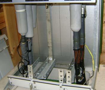
16 1YJM Rev E 16 / Main Cable Boxes The front cable box compartment covers can be removed provided the circuit earth is applied. Side and division panels can then be removed to expose all the cable bushings to give maximum cable termination room. Stands available include optional bolt on cable box inner panels, gland plates, cable support brackets. 4.3 Cable Connection The maximum cable recommended is 300mm² three-core or 500mm² for single-core cables. The bushings for each switch are arranged front to rear. The cable should be prepared for jointing with L1 to the rear. The cable-bushing stem is 25mm wide and lugs should be fitted using high tensile M12 bolts tightened to a maximum of 72Nm (max. bolt length recommended M12 x 35mm). Unused switches should be appropriately terminated with a blank termination Steps for Cable Connection Ensure that the switch is in the earth position to allow the front cover to be removed. Segregated cable boxes are provided. When the extreme left and right switches are earthed the outside cable box plates can be removed. Where the centre switch and one of the outside switches are turned to the earth position (for example during commissioning) the side plate between the two cable boxes can be removed to give more working space. Steps to install cabling: (a) Bolting lugs to the cable bushings (b) Right hand cable termination completed Cable termination boots The following cable termination boots have been type tested with SafeLink for a voltage impulse level of 95kV BIL in accordance with IEC Manufacturer Termination insulating boot type Cable size ABB Kabeldon KAP 300 XLPE 300 mm² Paper insulated 240 mm² ABB Kabeldon TB-A 12 U XLPE mm² Raychem RCAB-4120 XLPE mm² Euromold 15TS/NSS (cold shrink) XLPE mm² The SafeLink product is not designed to have heat shrink termination boots. The manufacturer s installation instructions are supplied with each kit and must be followed. For special situations (i.e. earth screen terminations) please seek further advice from your local ABB agent.

17 1YJM Rev E 17 / Outdoor Enclosure The outdoor enclosure to suit the SafeLink attaches to the ring main unit. It is padlockable and no special tools are required for its installation only an M8 socket and 4mm allen key are needed. Once installed all critical fixings are hidden. For access to the SafeLink unit, the top lifts up, and the door is hinged. The enclosure can be supplied in a flat-pack form for retrofitting or fully assembled. Full instructions for assembly and mounting are supplied with each enclosure. Dimensions and weights are detailed in section 3.5 on page 14.

18 1YJM Rev E 18 / 33 5 Operation The following sections describe the operating procedure for SafeLink. There are no parts within the SafeLink unit that require user attention other than the fuses and the gas density gauge. Equipment suffering faults or damage must be returned to your supplier for servicing. Ensure the gauge reads in the green area before switching. 5.1 Gas Density Gauge During operation, the gas density of the SafeLink unit should be in the green region. The gas pressure has been factory set to 1.2bar absolute (at 20 C). The gas density gauge differs from a simple pressure indicator in that it is temperature compensated The accuracy of the gas density gauge varies slightly with temperature; it is ± 1% at + 20 C (i.e. ± 20 mbar) and ± 2.5 % (i.e. ± 50 mbar) at the working limits of the gauge - 20 C/+60 C. All units are tested for gas tightness during production to ensure any gas leakage rate is less than 0.1% per annum (maximum mbarl/s using helium). Gas filling is through a valve at the front of the unit. See section 6.3 on page 27 for further details.
 General: Insertion of the operating handle is controlled by a rotary selector, which has one of")


19 1YJM Rev E 19 / General Switch Operation SafeLink Operating Instructions (Check gauge pressure before operating) General: Insertion of the operating handle is controlled by a rotary selector, which has one of three possible states: 1. Handle access BLOCKED & switch is padlockable in all states. 2. Switching between OFF & ON possible. 3. Switching between OFF & EARTH possible. Cable access cover can only be removed when the associated switch is in EARTH, the operating handle removed and the selector in the middle, BLOCKED, position. Configuration CFC Fuse access door Ring switch Ring switch Fuse access door can only be opened when the switch fuse is in EARTH and the selector in the middle, BLOCKED, position. Selector Switch Fuse SWITCHING RING SWITCHES & SWITCH FUSE OFF to EARTH: Move selector to the LEFT Insert operating handle Rotate handle ANTI-CLOCKWISE EARTH to OFF: Move selector to the LEFT Insert operating handle Rotate handle CLOCKWISE Check mimic panel and switch position indicators as shown OFF to ON: Move selector to the RIGHT Insert operating handle Rotate handle CLOCKWISE ON to OFF Move selector to the RIGHT Insert operating handle Rotate handle ANTI-CLOCKWISE Check mimic panel and switch position indicators as shown Earthing switch Circuit switch Earth Open Close Rotation Close Close Open Rotation SWITCH FUSE RESET RESET (after fuse initiated TRIP) Switch will automatically TRIP to OFF. RESET appears above the handle socket. Switch must be RESET to allow further operation. Move selector to the right. Insert operating handle. Rotate handle ANTI-CLOCKWISE to end of travel. Once RESET the selector will operate as normal. Check mimic panel and switch position indicators as shown Open Open Open Reset


 will be indicated by the canister(s) with the extended white plastic pin(s).")

20 1YJM Rev E 20 / 33 FUSE ACCESS (Switch fuse must be in EARTH & Selector in middle Blocked position) When a fuse is blown, there is indication via the striker mimic on the fuse door. This indicator is BLACK when all fuses are healthy and the door is closed, and turns RED if there is a blown fuse. To gain access to the fuse compartment the switch fuse must be in the earth position and the selector in blocked position before the door can be opened. The door knob will not fully rotate and release the door unless these conditions are met. This ensures that the internal earthing of both ends of the fuse is in place before access is available. Rotate the fuse access door knob anti-clockwise to open. Ensure knob is rotated fully to lock or unlock. Fuses healthy Unlocked Locked Fuse Blown Once the door is opened, the fuse canisters are visible. The blown fuse(s) will be indicated by the canister(s) with the extended white plastic pin(s). All three fuses should be replaced as a set. With the fuse door open, the roof section can be hinged up to allow improved access to the fuse handles. Pull the red handle on the front of the canister fully downwards. This will allow the fuse assembly to be removed. Central fuse assembly and fuse being withdrawn. Release the fuse from the fuse assembly clamp with a screwdriver. Fit the new fuse into fuse assembly and tighten clamp. Do not over tighten the clamp screw. Make sure that the striker is in the direction of the fuse sealing cap. Carefully refit the fuse and fuse assembly into the canister. The cap must be clean of grease or dirt. Push the red handle fully upwards to lock the fuse and fuse sealing cap into position. When the fuse door is closed ensure that nothing obstructs the fuse striker mechanism slots. If these slots are blocked, fuse tripping operation may not occur. Do not obstruct these holes CABLE BOX ACCESS The cable box access covers can only be removed with the corresponding switch in EARTH position and with the selector in the middle BLOCKED position. For cable testing it is possible to switch from EARTH to OFF only. The switch must be returned to EARTH to replace the cover. Once the cover is removed the switch can only be operated in the EARTH OFF sector. The selector will not move into the ON OFF sector, so the switch cannot be ON with a cable box cover removed. EARTH state & selector in middle Cover removed
21 1YJM Rev E 21 / Fuse Types and Replacement The fuses used must comply with IEC :1994 (High-voltage fuses - Part 1: Current-limiting fuses) having medium striker energy of 1J ± ½J. It is important that care is taken with the fuse alignment when installing small diameter fuses (i.e. less than 87mm). The fuse canister is completely sealed to IP65. Fuse links must have a barrel length of 292mm and dimensional compliance to DIN To replace a fuse, undertake the steps outlined above. For switch-fuse reset procedure see section 5.2 on page 19. Note that the switch will not remain in the closed position if a blown fuse is present. Auxiliary switches are available to give an additional indication of the fuse trip status. Avoid dirt on the rubber plug; do not apply grease, apply dry lubricant (talc). The fuse canister and tripping mechanism must be kept clean and dry. Discard and replace all three fuses when any fuse has operated (refer to fuse manufacturer s recommendations). 5.4 Fuse Tables 100% Transformer rating (kva) 630A Un (kv) Fuse Link Rating (A) The table is based on using fuse types ABB CEF (SIBA 160A) Fuse barrel length = 292mm Normal operating conditions with no transformer overload Ambient temperature 25 C + 40 C 130% Transformer rating (kva) 630A Un (kv) Fuse Link Rating (A) * *160 The table is based on using fuse types ABB CEF (SIBA 160A) Fuse barrel length = 292mm Normal operating conditions with 30% transformer overload Ambient temperature 25 C + 40 C * Maximum continuous overload 120%

22 1YJM Rev E 22 / Cable Box Interlock The cable box has been designed for arc fault containment using a double skin on the side and front panels. To gain access to the cable box the associated switch must first be in the earth position and the selector switch in the blocked position. This action also engages an interlock to prevent the switch being closed while the cover is removed. This allows the cable box cover to be lifted off. Type B has a secondary inner bolt on type panel. When refitting the cable box covers ensure that all bolts are in place, tightened and the cover is pushed fully down onto the locating pins. SafeLink Cable Box Covers & Panels removal instructions - Configuration CFC Type A and Type B (with secondary inner bolt on type panels) All Switches to be in the EARTH position & Selectors in middle Blocked position) Lift cable box covers upwards and pull out from the bottom section (same procedure for type A & B) Lift up and pull out Cable box covers removed


23 1YJM Rev E 23 / 33 Type B has secondary inner bolt on type panels. Remove the bolts on the inside to remove inner panel. To remove the two side panels, remove the two top and bottom mounting bolts. (same procedure for type A & B) Pull right hand side panel forward to remove (same procedure for type A & B)


 Pull")


24 1YJM Rev E 24 / 33 Removing inner partitions Remove top and bottom bolts (same procedure for type A & B) Pull forward to remove right and left hand centre partitions (same procedure for type A & B) Pull left hand side panel forward to remove. (same procedure for type A & B) All side panels and inner partitions removed


25 1YJM Rev E 25 / 33 Remove kick plate cover (type B only) Remove the 2 bolts and the kick plate cover. Then remove the kick plates same as type A below. Remove kick plates Remove bolts as shown and remove kick plates (type A & B) When re assembling, the bolts holding the kick plates are to be left loose to allow proper alignment prior to tightening securely. Cable box ready for cables to be terminated. Note: All bolts have to be replaced during assembly. If this is not done it could affect the proper operation of the interlocking and compromise safety. 5.6 Cable Testing Cable testing first requires that the cable box cover be removed as described above. The switch can then be taken out of the earth position to the off position. To allow test connections to be made to the cable, the termination boots must be slid down to reveal the bushing stems and the terminations. Once the cable box cover is removed a mechanical interlock prevents the switch being turned to the on position. The switch must be returned to the earth position before the cover is refitted. The cover catch locks automatically once the switch is taken out of the earth position. Cable testing should be carried out in accordance with the cable manufacturer s recommended practice. It is important that the terminations be done in the manner outlined in section 4.3 on page 16
26 1YJM Rev E 26 / Voltage and phase balance test It is recommended to conduct voltage and phase balance tests with the equipment shown below Voltage Indicator Phase balance tester

27 1YJM Rev E 27 / 33 6 Maintenance 6.1 Environmental The SafeLink switching enclosure is a gas-tight welded stainless steel compartment able to withstand a harsh environment. However, it is important that the base of the SafeLink installation be kept free of vegetation or other material to prevent corrosion of the stand and/or enclosure SF 6 Gas This equipment contains SF 6 gas; SF 6 is a fluorinated greenhouse gas covered by the Kyoto Protocol and has a global warming potential factor of The equipment is a sealed pressure system according to IEC The fluorinated greenhouse gas in this equipment may not be vented to the atmosphere. The SF 6 gas contained in this electrical equipment shall be recycled. The mass of SF 6 placed into the SafeLink equipment at the time of filling is approximately as follows: Configuration Mass CFC, CCC, XXX 0.8kg UK, CFCC, CCCC, XXXX 1.0kg CFCF 1.1kg A label identifying the equipment as containing SF 6 gas is placed adjacent to the filling point, and has the following format: 6.2 Maintenance All components within the SF 6 insulated tank are maintenance free for the life expectancy of the unit. The tank is made of stainless steel. Scratches or other damage to panels must be repaired. Mechanical parts located outside the sealed tank are surface treated or made of corrosion resistant materials. Moving parts are lubricated, as necessary during manufacture, for the unit s life expectancy. Units installed in harsh environments will require regular inspection and maintenance. Where an outdoor enclosure is used, this should be checked periodically and the base of the stand must be kept clear of vegetation and well ventilated. 6.3 Gas Filling The gas density gauge on the front of the SafeLink shows the density of SF 6 gas in the unit. All units are tested to ensure that any leakage rate is so low as to give a thirty-year service life. During switching, the arc formed will cause the gas to dissociate. Once the arc is extinguished the SF 6 reforms. A molecular sieve is fitted inside the switching enclosure to absorb any remaining decomposition products.
28 1YJM Rev E 28 / 33 Gas filling is performed through the gas density gauge fitting on the front of the unit. The ABB filling adaptor should be used and this allows the pressure inside the switch to be monitored during filling. This will ensure that any gas escaping during the filling process is minimised. Full details are included with the filling adaptor kit. 6.4 Environmental Certification Environmental Declaration for SafeLink SF 6 Insulated Ring Main Unit Life Expectancy of Product The product complies with the requirements denoted by (IEC ). The designed life span under indoor service condition exceeds 30 years. The switchgear is gas-tight with an expected diffusion rate of less then 0.1% per annum. Referring to the reference-pressure of 1.2 bar, the switchgear will maintain gas-tightness and a gas-pressure better than 1.1 bar* throughout its designed life span. (* at 20 C) 6.5 Recycling Capability Raw Material Amount (kg) % of total weight Recycle Environmental effects & recycle/reuse processes Iron Stainless Steel Copper Zinc Brass Silver Thermoplastic % 27.24% 10.85% 2.31% 0.74% 0.03% 1.33% Yes Yes Yes Yes Yes Yes Yes Separate and (re)melt Separate and (re)melt Separate and (re)melt Separate and (re)melt Separate and (re)melt Separate and (re)melt Separate and make pellets or burn for energy Rubber SF 6 gas % 0.41% Yes Yes Burn for energy ABB reclaims used SF 6 gas Total for recycling % Epoxy % Returns 60% silicon ash if burned for energy Epoxy Resin Fibre % Landfill Total Weight ** Wood (packing) Yes Reuse or burn for energy ** All figures were collected from first generation CFC 3-way ring main unit End-Of-Life ABB is committed to the protection of the environment and adheres to ISO standards. It is our obligation to facilitate end-of-life recycling for our products. ABB can arrange to reclaim SF 6 gas from discarded switchgears. There are no explicit requirements for how to handle discarded switchgears at end-of-life. ABB s recycling service is according to IEC edition 1995 section 6: {End of life SF 6 filled equipment} and in particular a: {Low decomposition}: No special action is required; non-recoverable parts can be disposed of normally according to local regulations.


29 1YJM Rev E 29 / 33 7 Accessories 7.1 Fault Passage Indicators Earth Fault and/or Short Circuit Indicator To DIN standard 7.2 Remote LED indicator This module gives a bright red LED indication if there is a fault. The module is mounted on the inside of the enclosure door in such a way that it is visible externally. 7.3 Voltage Indicator This device plugs into the panel mounted voltage detector system interface and monitors the voltage on the cable bushings. Each cable bushing has a built in capacitive screen, which is wired to 4mm plugs on the front panel. Each switch has a plug-set to accept the display module. This gives a flashing LED indication when voltage is present.


30 1YJM Rev E 30 / Phase Comparator Before closing a new incoming feeder or ring current to a live SafeLink ring main unit, check phase balance with the phase comparator. 7.5 Auxiliary Switch Snap action double-break switch with forced contact opening and self cleaning contacts. 1 x Normally Open contact and 1 x Normally Closed contact per block. It is possible to fit two blocks per Main switch and two blocks per Earth switch including the switch-fuse module. One block can also be fitted to indicate fuse blown. Ratings: I th 10A Vac 380 Vdc 450 V withstand 2500V 7.6 Motor Operator Available to be fitted to any main ring switch Fitted behind mimic panel Available in 24Vdc and 230Vac, other voltages on request Manual override is standard Plug-in control box that houses battery and remotes can be supplied to fit within the outdoor enclosure space. 7.7 Gas Density Monitor Pressure indicator is supplied as standard on all SafeLink Ring Main Units. Remote indication can also be provided as an option providing 1 or 2 micro switches 5A / 250 Vac, 50 Hz. The gas density monitor must be specified with order.


 Durable 3mm Hot Dip Galvanised construction 7.")
31 1YJM Rev E 31 / Shunt Trip Available in 24Vdc and 230Vac, other voltages on request The shunt trip can be retrofitted to any SafeLink RMU. 7.9 Cable Clamp Rail Adjustable for cable size Suitable for Unistrut K series clamps or equivalent. (Not included) Durable 3mm Hot Dip Galvanised construction 7.10 Bottom Cover/Gland Plates 7.11 Manual Trip Available to be fitted to the switch-fuse transformer feed.


32 1YJM Rev E 32 / Gas Filling/Sampling Adaptor Kit Allows access to gas enclosure via the density gauge shut-off connecting valve Fitted with ¼ NPT nipple for connection to bottle regulator set (not supplied) See instruction sheets for connection and procedure details 7.13 Extended Height Plinth Extends the height by 300mm Fits to the base of a SafeLink RMU Available in three sizes to suit width of the RMU 7.14 TB-A 12 U Kabeldon Termination Boot 12kV mm² 7.15 Lifting Frame Suitable for lifting SafeLink RMU s fitted to standard concrete plinths. Text and illustrations are not binding. The right to make alterations is reserved.
33 1YJM Rev E 33 / 33 Copyright Document 2009 ABB, All rights reserved Document Title SafeLink Manual Document No. Lang. Rev. Date No. of Pages Page 1YJM Rev E 14/01/
abb SafeLink SF 6 Insulated Ring Main Unit Installation and Operating Instructions Switchgear Division Auckland, New Zealand SLMIO ver 2.
 Installation and Operating Instructions Switchgear Division Auckland, New Zealand SLMIO ver 2.12 Product Overview ABB's type-tested ring main unit (RMU) is an SF 6 insulated RMU utilising the latest developments
SafeLink SF 6 Insulated Ring Main Unit Installation and Operating Instructions. ABB Power Technology Products Division NZABBSL 3001.
 ABB Power Technology Products Division abb Product Overview ABB's type-tested ring main unit (RMU) is an SF 6 insulated RMU utilising the latest developments in switchgear technology to provide a very
SafeLink The Ultimate RMU. Rex de Bruyn PTMV New Zealand. ABB Ltd - Page 1 ABB
 Rex de Bruyn PTMV New Zealand SafeLink The Ultimate RMU Ltd - Page 1 TheSafe Range of Ring Main Switchgear SafeLink : 12kV Compact Fuse Technology SafeRing : 12-24kV Fuse & Circuit Breaker Technology SafePlus
DISTRIBUTION SOLUTIONS. GSec Gas-insulated switching and isolating apparatus
 DISTRIBUTION SOLUTIONS GSec Gas-insulated switching and isolating apparatus GSec is a three-position SF6 gas-insulated switchdisconnector designed for use in medium voltage switchgear for secondary distribution
TECHNICAL SPECIFICATION OF 11KV SF6 / VCB METAL ENCLOSED, INDOOR (PANEL TYPE) / OUTDOOR RING MAIN UNIT (RMU). (IEC standard equipment)
 / OUTDOOR RING MAIN UNIT (RMU). (IEC standard equipment)") TECHNICAL SPECIFICATION OF 11KV SF6 / VCB METAL ENCLOSED, INDOOR (PANEL TYPE) / OUTDOOR RING MAIN UNIT (RMU). (IEC standard equipment) 1 SCOPE OF SUPPLY This specification covers design, manufacture, shop
TECHNICAL SPECIFICATION OF 11KV SF6 / VCB METAL ENCLOSED, INDOOR (PANEL TYPE) / OUTDOOR RING MAIN UNIT (RMU). (IEC standard equipment) 1 SCOPE OF SUPPLY This specification covers design, manufacture, shop
Product manual. SafeRing/SafePlus 36 kv SF 6. insulated Ring Main Unit and Compact Switchgear
 Product manual SafeRing/SafePlus 3 kv SF insulated Ring Main Unit and Compact Switchgear 2 SAFERING/SAFEPLUS 3 KV PRODUCT MANUAL Contents 003 005 00 007 009 0 01 015 020 021 022 022 023 1. General description
CGMCOSMOS. Reliable innovation. Personal solutions. Fully gas insulated modular and compact (RMU)system.
system.") MV Switchgear for CGMCOSMOS Fully gas insulated modular and compact (RMU)system Up to 24 kv Up to 27 kv mediumvoltage mediumvoltageag AG Langackerstrasse Langackerstrasse 25 25 CH CH 6330 6330 Cham Cham
MV Switchgear for CGMCOSMOS Fully gas insulated modular and compact (RMU)system Up to 24 kv Up to 27 kv mediumvoltage mediumvoltageag AG Langackerstrasse Langackerstrasse 25 25 CH CH 6330 6330 Cham Cham
SABRE VRN2a ENGINEERING BRILLIANT SOLUTIONS
 SABRE VRN2a ENGINEERING BRILLIANT SOLUTIONS Design The Sabre VRN2a is a compact SF6 insulated Vacuum Ring Main Unit (RMU). The unit can be mounted to the smallest distribution transformer or be sited in
SafeRing / SafePlus SafeRing / SafePlus
 SafeRing / SafePlus ABB / PTMV 1 Contents 1. General description... 3 1.1 Table of locations... 4 1.2 Dimensional drawings... 5 2. Transport and handling... 6 2.1 By receiving Inspection... 6 2.2 Storage...
Switchgear Type 8BT1, up to 24 kv, air-insulated. Medium Voltage Switchgear Catalog HA 26.
 www.siemens.com/medium-voltage-switchgear Switchgear Type 8BT1, up to 24 kv, air-insulated Medium Voltage Switchgear Catalog HA 26.31 2012 Answers for infrastructure and cities. R-HA26-013. eps Contents
ZX1.5-R. Gas-insulated medium voltage for railway application DISTRIBUTION SOLUTIONS. Gas-insulated medium voltage for railway application ZX1.
 DISTRIBUTION SOLUTIONS ZX1.5-R Gas-insulated medium voltage for railway application Safety and reliability 20% footprint saving Easy operation Complete solution ZX1.5-R Gas-insulated medium voltage for
Type SIMOPRIME A4, up to 24 kv, Air-Insulated Medium-Voltage Switchgear
 Circuit-Breaker www.siemens.com/energy Switchgear Type SIMOPRIME A4, up to 24 kv, Air-Insulated Medium-Voltage Switchgear s Technology Circuit-Breaker Switchgear Type SIMOPRIME, up to 17.5 kv, Air-Insulated
AIR INSULATED METAL ENCLOSED SWITCHGEAR AND CONTROLGEAR
 AIR INSULATED METAL ENCLOSED SWITCHGEAR AND CONTROLGEAR ANGLER SWITCHING DEVICES CONTENTS 1. General 2. Switchgear Types - Switch Disconnector - Disconnector 3. Cubicle Types - Cubicle with Switch Disconnector
Outdoor live tank SF 6. circuit breaker Type OHB for 24/36/40.5 kv applications
 Outdoor live tank SF 6 circuit breaker Type OHB for 24/36/40.5 kv applications ABB a global leader ABB is a global leader in Power and Automation technologies that enable utility and industry customers
Benefits, typical uses
 R-HA26-013. eps Switchgear Type 8BT1, up to 24kV,Air-Insulated Contents Application Page Application Benefits 2 Typical uses 2 and 3 Technical Data Ratings 4 Classification, dimensions, 5 room planning
Circuit-Breaker Switchgear Type SIMOPRIME, up to 17.5 kv, Air-Insulated Medium-Voltage Switchgear.
 Circuit-Breaker Switchgear Type SIMOPRIME, up to 17.5 kv, Air-Insulated Medium-Voltage Switchgear www.siemens.com/energy Technology s Contents Application Page Benefits 2 Typical uses 2 and 3 Technical
Key features. DESIGNS: - Conservator type - Hermetically sealed
 Package Substations OTDS manufactures a large range of oil filled hermitically sealed and conservator type transformers to be used in conjunction with our package substations. We are able to utalise the
56-SDMS-07 REV. 01 SPECIFICATIONS FOR
 56-SDMS-07 REV. 01 SPECIFICATIONS FOR UNIT SUBSTATIONS UP TO 36 kv ALUMINUM TRANSFORMER ALUMINUM BUS BARS LVDP This specification is property of SEC and subject to change or modification without any notice
PIX-H Metal-clad switchgear up to 17.5kV
 AIR INSULATED SWITCHGEAR PIX-H Metal-clad switchgear up to 17.5kV for high rated applications Technical Specifications AREVA T&D Summary - Technical description... 3 - Standards... 6 - PIX in detail...
Extensible Unit - VCE2a
 ELECTRICAL INDUSTRIAL COMPANY (EICo) LUCY SWITCHGEAR Extensible Unit - VCE2a (Sabre) Electrical Industrial Company (EICo) Lucy Switchgear Extensible Unit VCE2a Front Panel: ELECTRICAL INDUSTRIAL COMPANY
NXPLUS C Single busbar. Maintenance-free for lifetime
 NXPLUS C Single busbar Maintenance-free for lifetime Energy Distribution Welcome! Page 2 Content Overview Technical data Typicals Panel design Circuit-Breaker panel Busbar Operation Metering Low-voltage
UniPack compact secondary substations (CSS) upto 36 kv For safe, reliable and space saving power distribution solutions
 upto 36 kv For safe, reliable and space saving power distribution solutions") UniPack compact secondary substations (CSS) upto 36 kv For safe, reliable and space saving power distribution solutions ABB a global leader ABB is a global leader in power and automation technologies that
UniPack compact secondary substations (CSS) upto 36 kv For safe, reliable and space saving power distribution solutions ABB a global leader ABB is a global leader in power and automation technologies that
Typical Specification
 Engineered to Order Built to Last Typical Specification VAULT VRPFI, TWO POSITION, ROTARY PUFFER SWITCHGEAR PART 1- GENERAL 1.1 DESCRIPTION A. The switch shall consist of manually operated load interrupting,
M-RING 24. SF6 Insulated Ring Main Unit Metal-Enclosed (LSC2A)
") M-RING 24 SF6 Insulated Ring Main Unit Metal-Enclosed (LSC2A) Contents General Description Advanced facilities and process Advanced design philosophy Definition of M-RING 24 Standards Service conditions
M-RING 24 SF6 Insulated Ring Main Unit Metal-Enclosed (LSC2A) Contents General Description Advanced facilities and process Advanced design philosophy Definition of M-RING 24 Standards Service conditions
All rights reserved. Neither this catalogue nor any part of it may be copied using any method or for any purposes. Most studies are legally protected.
 Issued: January 2013 Copyright by ZPUE Katowice S.A. All rights reserved. Neither this catalogue nor any part of it may be copied using any method or for any purposes. Most studies are legally protected.
Gas Insulated Metal-clad Switchgear, HMGS!
 Medium Voltage HMGS-G10 HYUNDAI Medium Voltage Gas Insulated Metal-clad Switchgear, HMGS! SF6 Gas Insulated Metal-clad Switchgear is an integrated assembly of vacuum circuit breaker, 3-position switch,
the safe, reliable, and efficient choice for MV switchgear
 Power Xpert UX IEC Medium Voltage switchgear Tested to IEC 62271-200 17.5 kv up to 50 ka - 3 s 24 k V up to 25 ka - 3 s Air insulated switchgear Internal arc classified LSC2B-PM UX the safe, reliable,
Medium Voltage Products SafeLink CB SF 6. insulated secondary distribution compact Ring Main Unit
 Medium Voltage Products SafeLink CB SF 6 insulated secondary distribution compact Ring Main Unit Table of contents Applications 3 Design philosophy 5 Features overview 6 Configurations 7 Technical data
COMPACT SUBSTATION GUIDE
 COMPACT SUBSTATION GUIDE Certificate Number FM35831 1 The substation is a compact enclosure consisting of MV switchgear, a transformer and an LV switchboard located in three separate compartments which
SF 6. -insulated Ring Main Unit, SafeRing 36 and -insulated Compact Switchgear SafePlus kv ABB
 - Ring Main Unit, SafeRing 36 and - Compact Switchgear SafePlus 36 36 kv Contents 1. Contents 1. Application... 3 1.1 Applications SafeRing... 3 1.2 Applications SafePlus... 5 2. Design Philosophy... 7
CONTENT. EPE METALCLAD SWITCHGEARS AMS SERIES 12kV AMS METALCLAD SWITCHGEAR 24kV AMS METALCLAD SWITCHGEAR 40.5KV AMS METALCLAD SWITCHGEAR
 CONTENT EPE METLCLD SWITCHGERS SERIES EPE 1220 / - 12KV METLCLD SWITCHGER EPE 10D - 12KV METLCLD SWITCHGER EPE 24-24KV METLCLD SWITCHGER EPE 36-36KV METLCLD SWITCHGER EPE METLCLD SWITCHGERS MS SERIES 12
VD4 Installation and service instructions kv A ka
 Medium voltage products VD4 Installation and service instructions 12... 36 kv - 630... 3150 A - 16... 50 ka Index For your safety! 1 I. Introduction 2 II. Programme for environmental protection 2 1. Packing
GE Industrial Solutions. User/Installation Manual for 4.76kV -15kV SecoBloc
 GE Industrial Solutions User/Installation Manual for 4.76kV -15kV SecoBloc Index General Scope...3 Standards...3 Operating conditions...3 Technical specification...3 Basic structure Features...4 Operation...4
SF 6 Gas Insulated Switchgear Type SDH314 / SDHa314 for 72.5 to 145 kv
 Three Phase Encapsulated Type SF 6 Gas Insulated Switchgear Type SDH314 / SDHa314 for 72.5 to 145 kv 06B1-E-0002 Small Space Requirement, High Reliability and Safety ー 72.5 to 145 kv GIS, SDH314/SDHa314
EMPAC Metal enclosed capacitor bank for wind applications
 EMPAC Metal enclosed capacitor bank for wind applications Introduction The EMPAC is a Metal Enclosed Capacitor Bank suitable for voltages between 1 kv and 36 kv for reactive compensation in MV networks
Pantograph disconnector type GW54, up to 550 kv Maximum reliability and minimal maintenance
 Pantograph disconnector type GW54, up to 550 kv Maximum reliability and minimal maintenance Table of contents 02 03 04 05 06 07 08 Disconnectors from ABB Maximum reliability and minimal maintenance Technical
Metal Clad VCBs ~ Mk1
 Metal Clad VCBs ~ Mk1 DUVI 150/40 ROLL ON FLOOR VCBs Range: 6kV, 00A, 1.5kA, 12kV, 150A, 40kA ( 4A000A Bus-Bars ) ` Widest range for MV (up to 6kV) Distribution Networks Megawin make metal clad VCB Panels
Content. Uniswitch. 1. Design philosophy Applications Switchgear construction Cubicle types... 9
 Content 1. Design philosophy... 3 2. Applications... 5 3. Switchgear construction... 6 4. Cubicle types... 9 4.1 Cubicle program... 9 4.2 Cubicle type SDC... 11 4.3 Cubicle with fuse, type SDF...12 4.4
Semi-pantograph disconnector type DSSP, up to 300 kv Maximum reliability and minimal maintenance
 Semi-pantograph disconnector type DSSP, up to 300 kv Maximum reliability and minimal maintenance Semi-pantograph disconnector type DSSP, up to 300 kv Maximum reliability and minimal maintenance 2 Semi-pantograph
SF6 LOAD BREAK SWITCH. Remote Controlled OCR TELE_1_2013.EN
 SF6 LOAD BREAK SWITCH Remote Controlled OCR TELE_1_2013.EN INDEX Overview IA780 MOTOR OPERATED Presentation Standards Structural Characteristics 3 3 3 Construction characteristics Components Breaking technology
TGK Prefabricated Substation Technical Data
 TGK Prefabricated Substation Technical Data Ref Item Data 1 General Technical 1.1 Frequency (Hz) 50 1.2 Transformer Rating (kva) 315/750 1.3 Transformer Primary Voltage (kv) 11 1.4 Transformer Secondary
DIN HV Distribution. DIN HV fuses are partial-range high voltage currentlimiting fuses for use in distribution circuits from kV.
 DIN HV Distribution DIN HV fuses are partial-range high voltage currentlimiting fuses for use in distribution circuits from 2.3-38kV. Their compact dimensions and non-venting characteristics make them
Descriptive bulletin. Medium voltage load interrupter switchgear Reliable, low maintenance and economical for distribution applications
 Descriptive bulletin Medium voltage load interrupter switchgear Reliable, low maintenance and economical for distribution applications General overview Reliable, low maintenance and economical Load Interrupter
SWITCHGEAR FOR SERVICE UP TO 36kV (CABLE AND OVERHEAD CONDUCTOR CONNECTED)
") PRODUCED BY THE OPERATIONS DIRECTORATE OF ENERGY NETWORKS ASSOCIATION Issue 3 2012 SWITCHGEAR FOR SERVICE UP TO 36kV (CABLE AND OVERHEAD CONDUCTOR CONNECTED) www.energynetworks.org 2012 Energy Networks
PRODUCED BY THE OPERATIONS DIRECTORATE OF ENERGY NETWORKS ASSOCIATION Issue 3 2012 SWITCHGEAR FOR SERVICE UP TO 36kV (CABLE AND OVERHEAD CONDUCTOR CONNECTED) www.energynetworks.org 2012 Energy Networks
017: 1998 CEB STANDARD RING MAIN UNIT CEYLON ELECTRICITY BOARD SRI LANKA
 017: 1998 CEB STANDARD RING MAIN UNIT CEYLON ELECTRICITY BOARD SRI LANKA CONTENTS PAGE 1. Scope 2 2. System Parameters 2 3. Service Conditions 2 4. Applicable Standards 3 5. Basic Features 4 6. Quality
Submersible Vacuum Fault Interrupters
 Submersible Vacuum Fault Interrupters UG Distribution Medium Voltage Vacuum Fault Interrupters Functional Specification Guide PS024002EN Functional Specification for 2.4kV to 17.5kV UG Distribution Medium
Product catalogue. ABB AS, Power Products Division SF 6. -insulated Ring Main Unit, SafeRing 36 and -insulated Compact Switchgear SafePlus 36
 Product catalogue ABB AS, Power Products Division SF 6 -insulated Ring Main Unit, SafeRing 36 and SF 6 -insulated Compact Switchgear SafePlus 36 Content Applications SafeRing 36... 3 Applications SafePlus
AIR INSULATED EXTENDABLE SWITCHGEAR UP TO 12KV GUIDE
 AIR INSULATED EXTENDABLE SWITCHGEAR UP TO 12KV GUIDE Certificate Number FM35831 APPLICATION Typical Uses and Classification The MSGair switchgear is used in transformer and switching substations mainly
General. Main electric circuits Fuses compartment Operating mechanisms Cables connection compartment
 General The switchgear must be suitable for 36 kv rated voltage and specifically conceived for the secondary distribution substations in M.V. with either ring or radial type networks. The switchgear must
Voltage Rated operating voltage [kv] Rated power frequency withstand voltage [kv] Rated lightning impulse withstand voltage [kv]
![Voltage Rated operating voltage [kv] Rated power frequency withstand voltage [kv] Rated lightning impulse withstand voltage [kv]](/thumbs/80/82203973.jpg "Voltage Rated operating voltage [kv] Rated power frequency withstand voltage [kv] Rated lightning impulse withstand voltage [kv]") BasisBlock MC 1 Standards and Regulations IEC 62271-200 ; VDE 0671-200 ; BS EN 62271-200 Technical Data MC1-12 MC1-24 Voltage Rated operating voltage [kv] 12 24 Rated power frequency withstand voltage
BasisBlock MC 1 Standards and Regulations IEC 62271-200 ; VDE 0671-200 ; BS EN 62271-200 Technical Data MC1-12 MC1-24 Voltage Rated operating voltage [kv] 12 24 Rated power frequency withstand voltage
cpg.0 GIS-type medium-voltage switchgear with full insulation in SF 6 gas, up to 40.5 kv in accordance with IEC Standards
 GIS-type medium-voltage switchgear with full insulation in SF 6 gas, up to 40.5 kv in accordance with IEC Standards General Instructions IG-123-EN, version 09; 04/09/2017 CAUTION! When medium-voltage equipment
ME Switchgear with Vacuum Circuit Breaker and Auto-jet II Switch with Ground Position
 LET S BE PACIFIC November 0 Volume Number 5 ME Switchgear with Vacuum Circuit Breaker and Auto-jet II Switch with Ground Position Federal Pacific has the capability to engineer, fabricate and assemble
013 : 2009 CEB SPECIFICATION MOULDED CASE CIRCUIT BREAKERS
 013 : 2009 CEB SPECIFICATION MOULDED CASE CIRCUIT BREAKERS FOR OVERHEAD NETWOKS CEYLON ELECTRICITY BOARD SRI LANKA Specification for MOULDED CASE CIRCUIT BREAKERS FOR OVERHEAD NETWOKS CEB Specification
vertical fuse switch disconnectors
 SWITCHGEAR ARS vertical fuse switch disconnectors - touch protection IP 30 from the front - fibre glass extra strenghtened, self extinguishing thermoplastics - double clearance between open contacts -
ZX2 Gas-insulated medium voltage switchgear
 Gas-insulated medium voltage switchgear Double busbar 13 8 10 12 11 10 9 8 7 2 1 3 4 5 6 2 Versatile Partitioned single or double busbar system for all applications even with the most demanding parameters
CGMCOSMOS Fully gas-insulated modular and compact (RMU) system Up to 24 kv
 system Up to 24 kv") Medium Voltage Switchgear Secondary Distribution CGMCOSMOS Fully gas-insulated modular and compact (RMU) system MV Switchgear Secondary Distribution Networks General description Introduction Ormazabal
Medium Voltage Switchgear Secondary Distribution CGMCOSMOS Fully gas-insulated modular and compact (RMU) system MV Switchgear Secondary Distribution Networks General description Introduction Ormazabal
Metal Clad Air Insulated Switchgear
 Metal Clad Air Insulated Switchgear 1/ SecoGear Metal Clad Switchgear Features Fully metal-clad Equipped with Embedded pole VCB Full Front access (can be installed against wall) Perfect interlocking system
ZX-Family Gas-insulated medium voltage switchgear
 ZX-Family Gas-insulated medium voltage switchgear Minimum overall costs ZX offers maximum economy The compact design of the panels reduces the space required and therefore the size of the station. Freedom
SF6 GAS INSULATED METAL ENCLOSED SWITCHGEAR (GIS)
") SF6 GAS INSULATED METAL ENCLOSED SWITCHGEAR (GIS) About company The «Elektroapparat» plant starts its operation in 1922 as a plant manufacturing high-voltage electrical equipment. During the first two
SF6 GAS INSULATED METAL ENCLOSED SWITCHGEAR (GIS) About company The «Elektroapparat» plant starts its operation in 1922 as a plant manufacturing high-voltage electrical equipment. During the first two
32-SDMS-01 REV. 02 SPECIFICATIONS FOR
 32-SDMS-01 REV. 02 SPECIFICATIONS FOR NON-EXTENSIBLE SF6 INSULATED RING MAIN UNIT, 17.5 KV This specification is property of SEC and subject to change or modification without any notice CONTENTS PAGE 1.0
32-SDMS-03 SPECIFICATIONS FOR
 SPECIFICATIONS FOR EXTENSIBLE SF6 INSULATED RING MAIN UNIT, 17.5 KV This specification is property of SEC and subject to change or modification without any notice CONTENTS PAGE 1.0 SCOPE 3 2.0 CROSS REFERENCES
Fuse-links type CEF-S Rated voltages: 6/12 kv 30/40.5 kv Rated currents: 6.3 A 63 A
 DISTRIBUTION SOLUTIONS Fuse-links type CEF-S Rated voltages: 6/12 kv 30/40.5 kv Rated currents: 6.3 A 63 A Superior performance versus standard fuses ensuring up to 40% faster protection in case of low
Medium Voltage Distribution PIX. Air Insulated Switchgear up to 24 kv PARS TABLEAU
 Medium Voltage Distribution PIX Air Insulated Switchgear up to kv PIX Air Insulated Switchgear up to kv The PIX system has been designed in accordance with international (IEC) standards, and gives an optimal
Technical Specification for 12kV and 24kV Powder Filled Current Limiting Fuse Links for Use in Switchgear (In Air)
") Ergon Energy Corporation Limited Technical Specification for 12kV and 24kV Powder Filled Current Limiting Fuse Links for Use in Switchgear ETS12-01-02 Specification ETS12-01-02 Ver 3 Contents 1. Purpose
Ergon Energy Corporation Limited Technical Specification for 12kV and 24kV Powder Filled Current Limiting Fuse Links for Use in Switchgear ETS12-01-02 Specification ETS12-01-02 Ver 3 Contents 1. Purpose
Fuse-links type CEF-VT Rated voltages 3/7.2 kv - 10/24 kv Rated current 0.5 A 6.3 A
 DISTRIBUTION SOLUTIONS Fuse-links type CEF-VT Rated voltages 3/7.2 kv - 10/24 kv Rated current 0.5 A 6.3 A Efficient protection of voltage transformer circuits Extending the lifetime of installed electrical
MEDIUM VOLTAGE AIR INSULATED ARC-RESISTANT LOAD BREAK AND DISCONNECT SWITCHES
 MEDIUM VOLTAGE AIR INSULATED ARC-RESISTANT LOAD BREAK AND DISCONNECT SWITCHES Description JRS arc-resistant fused/non-fused load break and fused/non-fused disconnect switches are available for applications
Guide Specification. Three-Phase Solid Dielectric Trident-SR with SafeVu Integral Visible Break
 Part 1-GENERAL 1.1 DESCRIPTION Guide Specification Three-Phase Solid Dielectric Trident-SR with SafeVu Integral Visible Break The switchgear shall consist of magnetically actuated solid dielectric insulated
Cable arrangement 15 Preparation for cable installation. 15 Installation of the cables 16 Finishing of the cable installation. 17 Examples.
 Transportation and storage.. 3 General. 3 Unpacking at installation site....... 3 Transfer of cubicles at installation site... 3 Weight.. 4 Temporary storage. 4 Erection at site 5 General. 5 The switchgear
CGMCOSMOS-2LV. MEDIUM-VOLTAGE SF 6 GAS-INSULATED RING MAIN UNIT UP TO 12 kv LIB
 IG-179-GB GENERAL INSTRUCTIONS FOR IG-179-GB General Instructions MEDIUM-VOLTAGE SF 6 GAS-INSULATED RING MAIN UNIT UP TO 12 kv LIB Transformer Substations Primary Distribution Switchgear Secondary Distribution
CPG.1 Gas insulated, single busbar cubicle range Up to 27 kv / 2000 A / 31.5 ka Up to 38 kv / 2000 A / 31.5 ka IEEE Standards
 Medium Voltage Switchgear Primary Distribution CPG.1 Gas insulated, single busbar cubicle range Up to 27 kv / 2000 A / 31.5 ka General description Presentation Ormazabal s CPG System includes the CPG.1
MV Air Insulated Switchgear TAP17. Technical Data TGOOD
 MV Air Insulated Switchgear TAP17 Technical Data TGOOD 2017.1 Operating environmental conditions Place of installation: Indoor or outdoor Ambient temperature: 25 ~ +40 (higher or lower temperature optional)
Contents. The RM6 range
 Ring Main Unit RM6 24 kv Catalogue 2009 The RM6 range Contents Presentation Applications 2 Range advantages 4 Experience of a world leader 6 Protecting the environment 7 Quality - Standards 8 The RM6 range
32-SDMS-02 SPECIFICATIONS FOR
 SPECIFICATIONS FOR MV METERED RING MAIN UNIT UP TO 36 KV This specification is property of SEC and subject to change or modification without any notice CONTENTS PAGE 1.0 SCOPE 3 2.0 CROSS REFERENCES 3
Medium Voltage Products SafeLink CB SF6 Insulated Secondary Distribution Compact Ring Main Unit
 Medium Voltage Products SafeLink CB SF6 Insulated Secondary Distribution Compact Ring Main Unit 1 Table of Contents Applications.. 3 Design Philosophy. 5 Features Overview. 6 Configurations 8 Technical
Manual for installation and operation HB 602/05 en. ZX2 Gas-insulated medium voltage switchgear
 Manual for installation and operation HB 602/05 en ZX2 Gas-insulated medium voltage switchgear Your safety first always! That s why our instruction manual begins with these recommendations: Operate the
UniGear. Technical Guide
 UniGear Technical Guide CONTENTS 0 CONTENTS 1.1 Compartments 1/2 1.2 Components of the structure 1/3 1.2.1 Hot-galvanized steel sheet 1/3 1.2.2 Painted steel sheet 1/4 1.2.3 Copper 1/5 1.2.4 Insulating
Michigan State University Construction Standards SECONDARY UNIT SUBSTATIONS PAGE
 PAGE 261116-1 SECTION 261116 PART 1 - GENERAL 1.1 RELATED DOCUMENTS A. Drawings and general provisions of the Contract, including General and Supplementary Conditions and Division 01 Specification Sections,
11kV Compact Switchgear. tec - range. Minimum to Zero SF6 Insulation Gas. Outec Controls
 11kV Compact Switchgear tec - range Minimum to Zero SF6 Insulation Gas. Outec Controls 1 tec xx - 11kV Switchgear Contents 1 tec CB - SF6 Free Switchgear... 3 1.1 Description:... 3 1.2 1.3 Features the
020: 2013 CEB SPECIFICATION MINIATURE CIRCUIT BREAKER (MCB)
") 020: 2013 CEB SPECIFICATION MINIATURE CIRCUIT BREAKER (MCB) CEYLON ELECTRICITY BOARD SRI LANKA Telephone: +94 11 232 0953 Fax: +94 11 232 3935 CONTENTS Page 1.0 Scope 3 2.0 System Parameters 3 3.0 Service
020: 2013 CEB SPECIFICATION MINIATURE CIRCUIT BREAKER (MCB) CEYLON ELECTRICITY BOARD SRI LANKA Telephone: +94 11 232 0953 Fax: +94 11 232 3935 CONTENTS Page 1.0 Scope 3 2.0 System Parameters 3 3.0 Service
Low-voltage switchgear MNS Light W. Installation, handling and operation. ABB LV Systems
 Low-voltage switchgear MNS Light W Installation, handling and operation ABB LV Systems MNS Light W switchgear is a flexible system that is primarily designed for motor control. The rated service voltage
SafeRing / SafePlus. SF6 insulated ring main unit and compact switchgear Installation and operating instructions
 Your safety first - Always That s why our instruction manual begins with the following recommendations: Only install / operate switchgear in an environment suitable for the installation / operation of
Q pole Pole Mounted Capacitor System
 Q pole Pole Mounted Capacitor System Introduction The ABB Qpole pole mount capacitor system is an economical solution for shunt reactive compensation on overhead distribution networks. The Qpole is suitable
GE Consumer & Industrial Power Protection. New. SecoGear kV Metal-clad Switchgear. GE imagination at work
 GE Consumer & Industrial Power Protection New SecoGear 12-24kV GE imagination at work General SecoGear metal-clad switchgear is designed and manufactured with advance technology and has been comprehensively
Air-insulated switchgear UniGear type ZS1
 Air-insulated switchgear UniGear type ZS1 ABB Power Technologies / 1-7074 D 12-03-2003 - Air-insulated switchgear UniGear type ZS1 ABB Power Technologies / 2-7075 D 1 2-03-2003 - Rated voltage kv 12 17.5
RAPIER DSB Disconnectors
 RAPIER DSB Disconnectors and Copper and Aluminium Substation Connectors ENGINEERING BRILLIANT SOLUTIONS Rapier DSB disconnector The Rapier Double Side Break 'DSB' range provides a powerful and cost effective
1ZSC AAA en, Rev. 6. Resin impregnated paper bushing, oil to SF 6., type GSBK Technical guide
 1ZSC563-AAA en, Rev. 6 Resin impregnated paper bushing, oil to SF 6, type GSBK Technical guide Original instruction The information provided in this document is intended to be general and does not cover
HHD. High Voltage Fuses German DIN Standard. The temperature limiting function of the fuse striker pin. Design and construction.
 HHD High Voltage Fuses German DIN Standard For Air & Gas Insulated Switchgear Indoor and Outdoor Application The striker pin system is connected by means of a high resistance parallel conductor. After
Outdoor live tank SF6 circuit breaker EDT with integrated current transformer up to 72.5 kv
 Outdoor live tank SF6 circuit breaker EDT with integrated current transformer up to 72.5 kv SF6 circuit breaker EDT with integrated current transformer ABB is a world leader in live tank circuit breaker
Technical Specification of GECOL. Packaged Transformers
 GES 26211 Technical Specification of GECOL Packaged Transformers (Revision history) Issued on: Jan. 01, 2007 General Electricity Company of Libya Contents 1 SCOPE AND SERVICE CONDITIONS... 6 1.1 SCOPE...
045 : 2000 CEB STANDARD
 045 : 2000 CEB STANDARD LOW VOLTAGE FUSE SWITCH DISCONNECTOR CEYLON ELECTRICITY BOARD SRI LANKA Specification for LOW VOLTAGE FUSE SWITCH DISCONNECTOR CEB Standard 045 : 2000 CEYLON ELECTRICITY BOARD No.
SWITCHCRAFT. Switchcraft Europe GmbH SWITCHCRAFT
 SWITCHCRAFT Switchcraft Europe GmbH Switchgear Product Overview igis Gas Insulated Switchgear isis Solid Insulated Switchgear icb - Vacuum Circuit Breaker iair - Air insulated switchgear panel Switchcraft
HHD HIGH VOLTAGE FUSES GERMAN DIN STANDARD. The temperature limiting function of the fuse striker pin. Design and construction.
 HHD HIGH VOLTAGE GERMAN DIN STANDARD FOR AIR & GAS INSULATED SWITCHGEARS OUTDOOR SWITCHGEARS The striker pin system is connected by means of a high resistance parallel conductor. After melting the main
SUBSTATION VACUUM CIRCUIT BREAKER (38KV)
") SUBSTATION VACUUM CIRCUIT BREAKER (38KV) For more than four decades, Myers Power Products has led the switchgear market in quality for the electric industry, delivering highly reliable products for utilities
SUBSTATION VACUUM CIRCUIT BREAKER (38KV) For more than four decades, Myers Power Products has led the switchgear market in quality for the electric industry, delivering highly reliable products for utilities
SUBSTATION VACUUM CIRCUIT BREAKER (25.8 / 27KV)
") SUBSTATION VACUUM CIRCUIT BREAKER (25.8 / 27KV) For more than four decades, Myers Power Products has led the switchgear market in quality for the electric industry, delivering highly reliable products
SUBSTATION VACUUM CIRCUIT BREAKER (25.8 / 27KV) For more than four decades, Myers Power Products has led the switchgear market in quality for the electric industry, delivering highly reliable products
MODEL ELC-12/60-D BATTERY CHARGER
 *32198* NATIONAL RAILWAY SUPPLY Installing, Operating and Service Instructions for the 12/60 Solid State Charger MODEL ELC-12/60-D BATTERY CHARGER PLEASE SAVE THESE IMPORTANT SAFETY AND OPERATING INSTRUCTIONS
SUBSTATION VACUUM CIRCUIT BREAKER (15.5KV)
") SUBSTATION VACUUM CIRCUIT BREAKER (15.5KV) For more than four decades, Myers Power Products has led the switchgear market in quality for the electric industry, delivering highly reliable products for utilities
SUBSTATION VACUUM CIRCUIT BREAKER (15.5KV) For more than four decades, Myers Power Products has led the switchgear market in quality for the electric industry, delivering highly reliable products for utilities
MEDIUM VOLTAGE PRODUCTS. Powerbloc Pre-assembled modules for building medium voltage switchgear
 MEDIUM VOLTAGE PRODUCTS Powerbloc Pre-assembled modules for building medium voltage switchgear Powerbloc are the ideal solution for replacing fixed circuit breakers with withdrawable circuit breakers,
Metal Clad Switchgears
 SNC Series Metal Clad Switchgears > up to 36 kv Rated Voltage > up to 2500 A Rated Current > up to 40 ka Rated Short Time Withstand Current > LSC-2B, PM, AFLR > In Confirmity with IEC 62271-1, 100, 102,
Power IT Air Insulated Cubicle Uniswitch
 - 1-4/2/2003 Secondary Distribution Switchgear Power IT Air Insulated Cubicle Uniswitch Table of Contents Market segment Ratings New for 2003 Technical features Advantages Market segment Uniswitch Switchgear
5kV to 38kV, 630 Amp to 4000 Amp Indoor or Outdoor Application
 The most advanced Arc-Resistant Switchgear, designed and built to provide maximum safety in the event of an Internal Arcing Fault. 5kV to 38kV, 630 Amp to 4000 Amp Indoor or Outdoor Application Page 1