Cable arrangement 15 Preparation for cable installation. 15 Installation of the cables 16 Finishing of the cable installation. 17 Examples.
|
|
|
- Elinor Long
- 5 years ago
- Views:
Transcription

1
2 Transportation and storage.. 3 General. 3 Unpacking at installation site Transfer of cubicles at installation site... 3 Weight.. 4 Temporary storage. 4 Erection at site 5 General. 5 The switchgear bed 5 Fastening of the switchgear to the floor. 5 Cubicle dimensions 6 Bottom dimension drawings. 7 Connecting cubicles.. 9 The busbar compartment. 10 The busbar connections 11 Connecting the switchgear to the earth electrode 14 Cable arrangement 15 Preparation for cable installation. 15 Installation of the cables 16 Finishing of the cable installation. 17 Examples. 17 Mounting of equipment.. 19 Mounting of circuit-breakers.. 19 Mounting of motor operating device UEMC 40 K8_ for UES-K3/2. 22 Mounting of auxiliary switches for UES-K3/2. 23 Mounting of position indication and operation set. 24 Mounting of motor operating device for UES-A3M/2 24 Mounting of auxiliary switches for UES-A3(M)/ Mounting of shunt trip-coil. 25 Installing of indicating system for current transformers afterwards 25 2
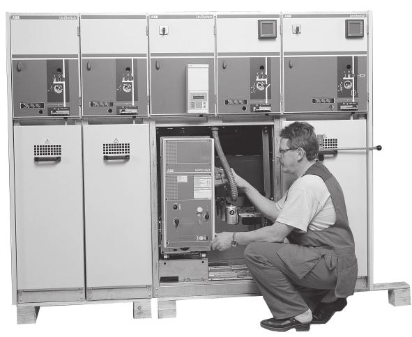
3 UniSwitch is delivered either as single cubicles or switchgear units with a length of no more than 2,0 m. The size of the package depends upon the number of cubicles and has to be defined separately for each case. The package of the switchgear is made according to ABB Transmit instruction 353 PAK 1A1. The switchgear can be transferred by a manual forklift or a forklift truck. The packages should be placed on a smooth base. The UniSwitch switchgear should only be installed indoors. Therefore it is important to store the switchgear cubicles in their transportation packages as long as possible. The packages should be opened only for inspection of possible transportation damages. After the inspection the package should be restored to original condition. Possible transportation damages should be reported immediately to the carrier/forwarder. If the installation of the switchgear is made right after the delivery, the transportation packages can be removed except the plastic film of the cubicles, which is to be removed at the final switchgear installation site. The cubicles can be transferred in a horizontal plane by a manual forklift or a forklift truck, exceptionally by means of rolling tubes (using at least four tubes). The switchgear cubicles are usually transferred in upright position. Leaning or overturning should be avoided. If necessary single cubicles can be leaned to horizontal plane e.g. because of low door height. In such a case the cubicle has to be supported from a wide area. If a crane is available lifting of a single cubicle is made with two lifting wire cables from the lifting lugs situated on the roof of the cubicle. When lifting several cubicles or a whole switchgear unit (4 cubicles at the most or a maximum length of 2 m) four lifting wires, long enough, should be used. Circuit-breaker cubicles must not be lifted with circuit-breaker installed in the cubicle. 3
4 Table 1a. The weight of different cubicles without packing. Approximate weight/kg Cubicle type Height = 1635mm Depth = 900 mm Width mm Height = 1885mm Depth = 900 mm Width mm SDC 1) SDF 2) CBC 3) DBC SEC SBC 3) BRC 1) SMC 3) ) without instrument transformers 2) without fuses 3) without circuit-breaker Table 1b. The weight of different devices. Device Approximate weight/kg Instrument transformer 12/17,5 kv 25 Instrument transformer 24 kv 30 Circuit-breaker HAD-US 100 Circuit-breaker VD4S 75 The package should immediately be taken indoors after having arrived. The conditions have to meet the environmental demands of the IEC standard, classification 1K3 (table 2). The maximum temporary storage time of the cubicles is 12 months. Inhibitors, placed in the cubicles for protection against humidity during temporary storage and transport, should not be removed before the end of the installation. Table 2. Climatic conditions according to IEC , classification 1K3. Low air temperature - 5 C High air temperature + 40 C Low relative humidity 5 % High relative humidity 95 % Rate of change of temperature 0,5 C/min 4
5 The switchgear is to be erected on a metal frame casted in the floor of the switchgear room or on a raised floor. When preparing the floor, the demands of the DIN standard should be applied. Particularly the straightness and uniformity of the base are important for a successful installation and should therefore be paid special attention to. The straightness of the floor should be ± 1 mm on the switchgear area. The load capacity of the floor should also be sufficient. If the switchgear consists of only a few cubicles, and there are no heavy cubicles included, it can be installed on the concrete floor. The metal frame is made of one or several parts depending of the size of the switchgear. The frame is casted in the floor when casting the surface of the floor. There is no height adjustment of the cubicles. Adjustment is made by installing steel plates under the cubicles. When designing cable ducts in the concrete floor the dimensioning drawings in chapter 2.5 should be applied. The switchgear can be fastened to the metal frame by welding through the holes of the bottom of the cubicle (2 welding seams/cubicle) or by two spline bolts/cubicle (M12) straight to the concrete floor. Fastening of a switchgear consisting of several cubicles can be done by fastening every second cubicle. The end cubicles of the switchgear should always be fastened according to the enclosed figure. The left-hand end cubicle is fastened from the left-hand front and the right-hand back corners of the cubicle floor. The right-hand end cubicle is fastened from the right-hand front and left-hand back corners. 5
6 The following drawings illustrate the main dimensions and the need of space of different cubicle types C 40 H = 1635 Alt H = 1885 A D B Cubicle types: SDC Cubicle types: CBC SDF SMC DBC SBC BRC SEC Table 3. Dimensions of CBC, SMC and SBC cubicles. Circuit breaker A B C D HAD-US 652 mm 215 mm 1155 mm 230 mm by H = mm by H = 1885 VD4S 652 mm 195 mm 1135 mm 130 mm by H = mm by H = 1885 There should be at least 250 mm pressure release space between the back of the switchgear and the switchgear room wall. This space should be closed by fastening a metalsheet (thickness at least 2 mm) between the back of the switchgear and the wall of the switchgear room (depth 250 mm and height 1865 mm). If the switchgear is situated in the middle of the switchgear room it has to be equipped with pressure relief channels. 6
7 W = 375 W = 500 W = D = D = D = 940 Ø Ø Ø W = 375 W = 500 W = D = D = D = Ø Ø Ø
8 W = 375 W = 500 W = D = D = D = 940 Ø Ø Ø


9 There are four 11x mm holes for 1635 mm high cubicles (five holes for 1885 mm high cubicles) in the front and back of the sidewalls for connecting the cubicles to each other in the cable compartment. The holes are vertical on the righthand sidewalls and horizontal on the lefthand sidewalls thus a small tolerance for erection is acceptable. The connection is made by a 10,5 washer, a M10x bolt and a M10 nut. The torque of the fastening bolts should be 10 Nm. In the secondary compartment the cubicles are connecting to each other through three 8 holes nearest the front of the secondary compartment. The connection is made with a 6,5 washer, a M6x slotheaded screw and a M6 nut. The torque of the fastening screws should be 5 Nm. To ensure the connection of the back upper part of the cubicles a back up strip of approximately cm length is mounted from above. The back up strip is pushed into the seam of the back upper part of the cubicles as down as possible. 9


10 As a final step in connecting the cubicles to each other the roof seams between the cubicles are secured. This is made by mounting a back up strip of the same length as the cubicle depth into the seams. The strip should be pushed so deep that the bending on the end of it touches the bottom edge of the seam. The strip must be fixed with a screw from its middle point. The busbar compartment is covered with the top plate. The top plate is fixed to the cubicle by screws from its front and back. There are 6 screws in the 375 mm wide and 8 screws in the 500 mm wide cubicle. The busbar compartment can be accessed by loosening the screws and removing the top plate. Note that the top plates of the end cubicles of the switchgear can not be removed. A warning sign is placed on the top plate indicating highvoltage beneath the roof. 10


11 The top plate of the cubicle is removed according section 2.7 before making busbar connections. The busbar connections in the end cubicles are made through the top openings of adjacent cubicles. The busbars are mounted with their bended end always to the right. In the left-hand end cubicle the busbar end is mounted to the terminal of the SFG switch-disconnector. A busbar shim made of copper and with the same thickness as busbar, is mounted on the busbar. In the right-hand end cubicle of the switchgear the busbar shim is mounted between the bended end of the busbar and the upper terminal of the SFG switch-disconnector. The busbar joints are made with a 10,5 spring washer and a M10x40 hexagon head bolt. The torque of the joint is 35 Nm. a,b c d d a,b d d a,b c Lefthand end cubicle Middle cubicle Righthand end cubicle a: Hexagon head bolt M10x40 b: Spring washer, hole 10,5 c: Copper busbar shim, outer diameter 30, height 8 mm, hole 10,5 d: Nonisolated 40x8 copper bar with rounded edges 24 kv busbar joints are made in the same manner as 12 and 17,5 kv busbar joints with the following exceptions. 24 kv busbars are always isolated. On the 24 kv busbar joints two-piece field control caps, consisting of aluminium part and EPDM-rubber part, are mounted according to the following figures. Aluminium cap with one cutout for end cubicles. Aluminium cap with two cutouts for middle cubicles (upsidedown). 11

12 EPDM-rubber cap with a low cutout for lefthand end cubicles. EPDM-rubber cap with a high cutout for righthand end cubicles. EPDM-rubber cap with two cutouts for middle cubicles (upsidedown). a,b c e f a,b e e e a,b c f f Lefthand end cubicle Middle cubicle Righthand end cubicle a: Hexagon head bolt M10x40 b: Spring washer, hole 10,5 c: Copper raising ring, outer diameter 30, height 8 mm, hole 10,5 d: Isolated 40x8 copper bar with rounded edges f: Field control cap (aluminium and EPDM-rubber) 12


13 Aluminium field control caps. Aluminium field control caps covered by EPDMrubber caps. The torque of the joint for other busbar connections is 35 Nm. Notice that the 24 kv busbar connections should be covered by a shrink tube according to the figure below. This applies also to the voltage transformer primary connection cable except the construction in which the connection cable is joined in a CBC-cubicle to a busbar between a current transformer and a fixed contact of earthing switch EM. 13

.")
14 The earth electrode is to be connected to the main earthing bar of the cubicle (3x30 mm Cu). The connecting point is marked with the equipment earth symbol. The connection is made with a 10,5 spring washer, M10x25 hexagonal head bolt and a M10 hexagonal nut. The connection bolt is tightened to a torque of 40 Nm. In larger switchgears (more than 8 cubicles) the earth electrode is connected to the both end cubicles of the switchgear. To secure the grounding via metal frame of the switchgear the main earthing bars can be connected together in the front of cubicles using additional earthing bars (3x30 mm Cu). The connection is made with an 8,4 spring washer, M8x30 hexagonal socket-head bolt and a M8 hexagonal nut. The connection bolt is tightened to a torque of Nm. 3 x 30 Cu 14


 Loose 4 screws from the baseboard in front of")
 Loose 4 screws from the door step and remove the")
15 a) Remove the door from the cable compartment. Notice. The door can be opened only when the switchdisconnector is in the earthed position and the locking unit is in the door open position. b) Loose 4 screws from the baseboard in front of the door step of the cubicle. c) Loose 4 screws from the door step and remove the door step from the cubicle by pushing it straight forward in its side steering tracks. 15
 Remove the front floor plate and the plastic cable sealing of phase L3. The rearmost floor plate of phase L3 should not be removed. Pull the cables through the open bottom into the cubicle.")
16 d) Remove the floor plates, including plastic parts, from phases L1 and L2 by pulling them forward in their side steering tracks. e) Remove the front floor plate and the plastic cable sealing of phase L3. The rearmost floor plate of phase L3 should not be removed. Pull the cables through the open bottom into the cubicle. Measure and cut the cables to sufficient length considering the installation of cable terminations and cable lugs. Bend the conductors of phase L1 and L2 out through the open front of the cubicle during the installation of the conductor of phase L3. a) Connection of the conductor of phase L3 Take the plastic cable sealing and thread it on the conductor. Measure the right length of the cable considering the right location of the sealing. Install the necessary cable termination and clamp an appropriate cable lug to the conductor. Loose the nut and spring washer of the connector. Hang the conductor from its cable lug on the bolt of the connector. Install the pressure relief washer, the spring washer and the nut. Tighten the connection to suitable tightness, in the switch-disconnector and circuit-breaker cubicles 55 Nm and the fuse switch-disconnector cubicle 35 Nm. Pull the front floor plate (aluminium) in its side guides tight to the rearmost floor plate and attach them together with M6 bolts. Considering the size of the conductor, take the right size of cable clamp and attach the cable with sufficient tightness to the rearmost bushing considering the straightness of the cable from the fixture to the connection bolt. b) Connection of the conductor of phase L2 Pull the rearmost floor plate (steel) of phase L2 in its side guides tight to the floor bushing of phase L3. Take the precut conductor of phase L2 and continue according to section 3.2 a. c) Connection of the conductor of phase L1 Pull the rearmost floor plate (steel) of phase L1 in its side guides tight to the floor bushing of phase L2. Take the precut conductor of phase L1 and continue according to section 3.2 a. 16
17 UniSwitch Installation manual a) Install and attach the door step of the cubicle, which was removed when preparing for cable connections (see 3.1 c). b) Install the baseboard in front of the threshold of the cubicle. (See 3.1 b). c) Check that the shields of the feeder (outgoing) cables are connected to the main earthing bar of the cubicle. Check also the wiring if current transformers are installed. 3.4 Examples Cable arrangements for switch-disconnector (SDC) cubicles. 17
18 By H/1635 fuse length 292 => 605 fuse length 442 => 455 By H/1885 fuse length 292 => 855 fuse length 442 => 705 L L By H/1635 = 400 mm By H/1885 = 650 mm Cable arrangements for switch-disconnector cubicle with fuse (SDF) and circuit-breaker cubicle (CBC). The clearance (L) of the VT primary connection cable should be at least 80 mm. 18

 35 (lower")

19 The circuit-breaker is to be lifted, preferably with a lifting truck. The correct tightening torques according to table 4 should be applied during the installation. Table 4. Tightening torques for different connections. Connection Torque/Nm Busbar-busbar 35 Busbar-HAD-US (upper poles) 35 (lower poles) Busbar-VD4-S 68 Busbar-SFG 35 Busbar-CT Before lifting the circuit-breaker take off the plastic covers and remove connection bars from the upper poles. 19


20 Lift the circuit-breaker up to the same level as the mounted circuit-breaker floor. Slide the circuit-breaker manually into its leader and push it in. Do not move lifting truck before the circuit-breaker is totally inside the cubicle because the breaker is very heavy in front. Mount the fixing plate at the bottom of circuit-breaker front with 4 fixing screws/nuts. Install the busbars starting with the lower poles of circuit-breaker. After that connect the busbar to the upper poles of circuit-breaker using the connection bar.


21 If 24 kv HAD circuit-breaker is to be installed the connection bars of the upper poles should be covered by field control cups before connecting the plastic covers. The busbars of 24 kv CBC, SMC and SBC cubicles should be covered by a shrink tube where possible. After mounting of the circuit-breaker put the white control pin into the cable terminal and connect the terminal to the circuit-breaker. Notice the correct position of the flexible tube (HAD-US). 21

 by pressing it with two fingers.")


22 Operate the SFG switch-disconnector to the earthed position. Move the interlocking selector to the Door open position. Open the cable compartment door and the secondary apparatus compartment door. Take off the plastic cover (A) by pressing it with two fingers. Loosen the four screws (B) and remove the interlocking unit. A B B B B Operate the SFG switch-disconnector to the open position. Unlock the position indication and operation set by loosening the locking ring and remove the set. Remove the cover plates (2 pcs) of UES-K3/2 and install the motor operating device. 22


23 Pull up the brass operation shaft and adjust the lifting arm in correct position according to the figure. Push the operation shaft back to the original position. Notice that the motor operating device does not have any fixing screws to tighten. The small play between the motor operating device and the limiting surface does not effect the operation of the mechanism mm Refit the cover plates, the position indication and operation set and the interlocking unit. Further information is available in installation and operating manual for UEMC 40 K8_. The auxiliary switches are to be mounted on the uppermost cover plate of UES-K3/2. Remove the uppermost cover plate and tighten the screws with a torque of max. 1,3 Nm. Use nyloc locking nuts behind the cover plate. Both screws must be tightened with a similar torque. Make sure that the mounting position of the auxiliary switches is correct and they are moving normally after mounting by pushing them. Earthing indication switches are located in the right hand side of cover plate. 23


24 The auxiliary switches are to be mounted on the cover plate of UES-A3(M)/2. Tighten the screws with a torque of max. 1,3 Nm. Both screws must be tightened with a similar torque. Make sure that the mounting position of the auxiliary switches is correct and they are moving normally after mounting by pushing them. Earthing indication switches are located on the right hand side of cover plate. The shunt trip-coil is to be mounted by means of 2 screws and washers. Some of the customers use current transformers which are not manufactured by ABB Transmit. In such cases the CT s are usually installed by a customer. If voltage indication via CT s is needed the following information should be taken into account. Voltage indicating system CL497/CL498 for CT s meets the requirements of IEC , if the value of capacitive divider C1 in CT is according to table 5. Table 5. The recommended values for capacitive dividers in CT s. Operating voltage (kv) Value of C1 (pf) 6 7, ,8 17, It is also recommended that the stray capacitance value of CT is between 90 pf. 25


25 The SFG switch-disconnector should be in open position. Lock the position indication and operation set with the locking ring. Check that the location of position indication shaft and disc is in accordance with the figure below. Notice the location of position indication shaft and disc in open position. Motor operating device for UES-A3M/2 is to be mounted by means of 3 screws and washers and the cover for it by means of a screw and a washer. 24
26
Power IT Air Insulated Cubicle Uniswitch
 - 1-4/2/2003 Secondary Distribution Switchgear Power IT Air Insulated Cubicle Uniswitch Table of Contents Market segment Ratings New for 2003 Technical features Advantages Market segment Uniswitch Switchgear
Content. Uniswitch. 1. Design philosophy Applications Switchgear construction Cubicle types... 9
 Content 1. Design philosophy... 3 2. Applications... 5 3. Switchgear construction... 6 4. Cubicle types... 9 4.1 Cubicle program... 9 4.2 Cubicle type SDC... 11 4.3 Cubicle with fuse, type SDF...12 4.4
Low-voltage switchgear MNS Light W. Installation, handling and operation. ABB LV Systems
 Low-voltage switchgear MNS Light W Installation, handling and operation ABB LV Systems MNS Light W switchgear is a flexible system that is primarily designed for motor control. The rated service voltage
Air-insulated switchgear UniGear type ZS1
 Air-insulated switchgear UniGear type ZS1 ABB Power Technologies / 1-7074 D 12-03-2003 - Air-insulated switchgear UniGear type ZS1 ABB Power Technologies / 2-7075 D 1 2-03-2003 - Rated voltage kv 12 17.5
Uniswitch M1 motor control kit installation instructions. Handled by Date Page Knutar K (14) 1MRS A
 1MRS A") Uniswitch M1 motor control kit installation instructions Handled by Date Page Knutar K. 26.5.2014 1 (14) 1MRS758190 A 1. Contents 2. Introduction... 2 3. Preparations... 3 3.1. Tools needed... 3 3.2. Preparations
Uniswitch M1 motor control kit installation instructions Handled by Date Page Knutar K. 26.5.2014 1 (14) 1MRS758190 A 1. Contents 2. Introduction... 2 3. Preparations... 3 3.1. Tools needed... 3 3.2. Preparations
KYN28A-12 (GZS1) A.C METALCLAD REMOVABLE SWITCHGEAR FOR INDOOR USE CHINATCS
 A.C METALCLAD REMOVABLE SWITCHGEAR FOR INDOOR USE CHINATCS") KYN28A-12 (GZS1) A.C METALCLAD REMOVABLE SWITCHGEAR FOR INDOOR USE CHINATCS 2001.09 KYN28A-12 (GZS1) A.C Metalclad Removable Switchgear for Indoor Use --------The Leader in Switchgear Up to 12kV 1. The
KYN28A-12 (GZS1) A.C METALCLAD REMOVABLE SWITCHGEAR FOR INDOOR USE CHINATCS 2001.09 KYN28A-12 (GZS1) A.C Metalclad Removable Switchgear for Indoor Use --------The Leader in Switchgear Up to 12kV 1. The
AIR INSULATED METAL ENCLOSED SWITCHGEAR AND CONTROLGEAR
 AIR INSULATED METAL ENCLOSED SWITCHGEAR AND CONTROLGEAR ANGLER SWITCHING DEVICES CONTENTS 1. General 2. Switchgear Types - Switch Disconnector - Disconnector 3. Cubicle Types - Cubicle with Switch Disconnector
AIR INSULATED EXTENDABLE SWITCHGEAR UP TO 12KV GUIDE
 AIR INSULATED EXTENDABLE SWITCHGEAR UP TO 12KV GUIDE Certificate Number FM35831 APPLICATION Typical Uses and Classification The MSGair switchgear is used in transformer and switching substations mainly
Energy Australia Chamber Substation indoor switchgear. installation,operation and maintenance instructions version 1.
 Energy Australia Chamber Substation indoor switchgear installation,operation and maintenance instructions version 1.6 / February 2009 1 Details of revision Version Comment Date 1.0 First Draft Issue May
PIX-H Metal-clad switchgear up to 17.5kV
 AIR INSULATED SWITCHGEAR PIX-H Metal-clad switchgear up to 17.5kV for high rated applications Technical Specifications AREVA T&D Summary - Technical description... 3 - Standards... 6 - PIX in detail...
MNS Light F. Low-voltage switchgear with fixed units. ABB LV Systems
 MNS Light F Low-voltage switchgear with fixed units ABB LV Systems Cubicle design MNS Light F switchgear is a flexible system with a large selection of cubicle variants that can be built together in optional
MEDIUM VOLTAGE CE-B36 METAL CLAD SWITCHBOARDS. CE - B36 - C - en - REV
 CE - B36 - C - en - REV.00 2011.9 EDIU VOLTAGE EDIU VOLTAGE APPLICATION CE-B etal Clad switchboards are designed for use in public and industrial distribution system up to 36kV for the operation and protection
ZX-Family Gas-insulated medium voltage switchgear
 ZX-Family Gas-insulated medium voltage switchgear Minimum overall costs ZX offers maximum economy The compact design of the panels reduces the space required and therefore the size of the station. Freedom
Gas Insulated Metal-clad Switchgear, HMGS!
 Medium Voltage HMGS-G10 HYUNDAI Medium Voltage Gas Insulated Metal-clad Switchgear, HMGS! SF6 Gas Insulated Metal-clad Switchgear is an integrated assembly of vacuum circuit breaker, 3-position switch,
MCset 4-24 kv Withdrawable SF6 circuit breaker
 Medium Voltage switchgear MCset 4-24 kv Withdrawable SF6 circuit breaker Instruction for use Contents General 2 Glossary 2 Symbols 2 Recommendations 3 General description 4 AD4 unit 4 AD4 unit with toroidal
UniSec Installation manual
 DISTRIBUTION SOLUTIONS UniSec Installation manual Index Safety 2 Introduction. Product information 4. Unit dimensions 4.2 Weights 7 2. Transport and storage 8 2. Condition on delivery 8 2.2 Unpacking at
Manual for installation and operation HB 602/05 en. ZX2 Gas-insulated medium voltage switchgear
 Manual for installation and operation HB 602/05 en ZX2 Gas-insulated medium voltage switchgear Your safety first always! That s why our instruction manual begins with these recommendations: Operate the
MEDIUM VOLTAGE CE-B METAL CLAD SWITCHBOARDS. CE-B-C-en-REV
 CE--C-en-REV.04 2016.1 MEDIUM VOLTAGE MEDIUM VOLTAGE APPLICATION CE- Metal Clad switchboards family are designed for use in public and industrial distribution system up to 40,5kV for the operation and
Units with pedestal and busbars on the short side (+H360, flat mounting)
") 91 Units with pedestal and busbars on the short side (+H360, flat mounting) Delivery check Check that there are no signs of damage. Before attempting installation and operation, check the information on
91 Units with pedestal and busbars on the short side (+H360, flat mounting) Delivery check Check that there are no signs of damage. Before attempting installation and operation, check the information on
SF 6 gas insulated RMU SafePlus 24 kv. ABB SafePlus 24 kv SF6 gas insulated RMU 1
 SF 6 gas insulated RMU SafePlus 24 kv 25.03.2010 SafePlus 24 kv SF6 gas insulated RMU 1 Secondary distribution 400 kv Transmission substation Transformer 40-70 kv 130 kv Main Substation Secondary distribution
Manual for installation and operation HB 602/14 en. ZX2 Gas-insulated medium voltage switchgear
 Manual for installation and operation HB 602/14 en ZX2 Gas-insulated medium voltage switchgear Your safety first always! That s why our instruction manual begins with these recommendations: Operate the
Environmental Product Declaration
 Environmental Product Declaration UniSwitch Medium Voltage Equipment Table of contents:. Environmental Product Declaration... 2. ABB... 2 2. ABB Transmit Oy... 2 2.2 ABB Transmit Oy, MV Systems Division...
All rights reserved. Neither this catalogue nor any part of it may be copied using any method or for any purposes. Most studies are legally protected.
 Issued: January 2013 Copyright by ZPUE Katowice S.A. All rights reserved. Neither this catalogue nor any part of it may be copied using any method or for any purposes. Most studies are legally protected.
CPG.1 Gas insulated, single busbar cubicle range Up to 27 kv / 2000 A / 31.5 ka Up to 38 kv / 2000 A / 31.5 ka IEEE Standards
 Medium Voltage Switchgear Primary Distribution CPG.1 Gas insulated, single busbar cubicle range Up to 27 kv / 2000 A / 31.5 ka General description Presentation Ormazabal s CPG System includes the CPG.1
Air-insulated switchgear with
 AIR-INSULATED SWITCHGEARS PIX 7 4 kv Air-insulated switchgear with vacuum switching devices Installation Operation Maintenance No. AMTNoT 060-0 Edition 03/009 Technical Manual AREVA T&D AREVA T&D Worldwide
DISTRIBUTION SOLUTIONS. GSec Gas-insulated switching and isolating apparatus
 DISTRIBUTION SOLUTIONS GSec Gas-insulated switching and isolating apparatus GSec is a three-position SF6 gas-insulated switchdisconnector designed for use in medium voltage switchgear for secondary distribution
Instruction for Installation and Operation
 KYN79 (i-ax) Metalclad Removable AC Metal-Enclosed Switchgear Instruction for Installation and Operation K 15 24 SM 01 02 Tianshui Changcheng Switchgear Factory January, 2007 Warning: This instruction
Gas Insulated Switchgear
 Gas Insulated Switchgear Your partner in energy solutions CG Electric Systems Hungary CG Electric Systems Hungary (previously known as Ganz Electric) has a history of over a 130 years as a high technology
PIX High. Medium-voltage switchgear. Air-insulated switchgear kv ( 50 ka) Assembly - Operation - Maintenance Technical Manual
 Assembly - Operation - Maintenance Technical Manual") Medium-voltage switchgear PIX High Air-insulated switchgear 7.5 kv ( 50 ka) Assembly - Operation - Maintenance Technical Manual No. AGS 53 50-0 Edition /04 www.schneider-electric.com Manufacturer: Schneider
Medium-voltage switchgear PIX High Air-insulated switchgear 7.5 kv ( 50 ka) Assembly - Operation - Maintenance Technical Manual No. AGS 53 50-0 Edition /04 www.schneider-electric.com Manufacturer: Schneider
Persian Tajhiz Niroo Engineering Co.
 01 blank 3 03 Persian Tajhiz Niroo Engineering Co. 05 07 19 51 61 Briefs History LV MV Prefabricated Substetion Pad Mounted Substetion Brief History 5 www.persiantajhiz.com Persian Tajhiz Engineering Group
UniGear. Technical Guide
 UniGear Technical Guide CONTENTS 0 CONTENTS 1.1 Compartments 1/2 1.2 Components of the structure 1/3 1.2.1 Hot-galvanized steel sheet 1/3 1.2.2 Painted steel sheet 1/4 1.2.3 Copper 1/5 1.2.4 Insulating
Persian Tajhiz Niroo Engineering Co.
 01 blank 3 Persian Tajhiz Niroo Engineering Co. 05 09 40 48 56 Briefs History MV LV Pad Mounted Prefabricated 5 www.persiantajhiz.com Brief History Stay Strong in Their own way... PERSIAN Tajhiz Engineering
10/2015 CUBICLE AND METAL-CLAD MEDIUM VOLTAGE SWITCHGEARS WEGA 07 WEGA 12 WEGA 17 WEGA 24 WEGA 36
 10/2015 CUBICLE AND METAL-CLAD MEDIUM VOLTAGE SWITCHGEARS WEGA 07 WEGA 12 WEGA 17 WEGA 24 WEGA 36 Gdańsk, October 2015 Improving the competitiveness of the company ELMOR through investments introducing
33KV INDOOR SWITCHGEAR
 33KV INDOOR SWITCHGEAR September 2017 Engineering Department WEST BENGAL STATE ELECTRICITY TRANSMISSION COMPANY LIMITED Regd. Office: VidyutBhawan, Block DJ, Sector-II, Bidhannagar, Kolkata 700091. CIN:
Page. Circuit-Breakers M4 2 for motor protection. Auxiliary contacts 3 Signalling switch Auxiliary releases
 Circuit Breakers M4 Page Circuit-Breakers M4 2 for motor protection Auxiliary contacts 3 Signalling switch Auxiliary releases Insulated 3-pole busbar system 4 Terminal block DIN-rail adapters 5 Busbar
24 k B788 ELEKTROTECHNISCHE WERKE FRITZ DRIESCHER & SÖHNE GMBH
 788 Instructions for Installation, Operation and Maintenance for DRIESCHER - Air - Insulated Medium - Voltage Compact Switchgears for Substations Rated voltage 12 kv and 24 kv Rated current 630 A 24 k
NXPLUS C Single busbar. Maintenance-free for lifetime
 NXPLUS C Single busbar Maintenance-free for lifetime Energy Distribution Welcome! Page 2 Content Overview Technical data Typicals Panel design Circuit-Breaker panel Busbar Operation Metering Low-voltage
MULTIBLOC 2.RST8 Size 2, 400A, 690VAC, Design for bus bar installation, Triple Pole
 MULTIBLOC 2.RST8 IEC FUSE SWITCH DISCONNECTORS NH FUSE SWITCH DISCONNECTOR The production programme of MULTIBLOC 2.RST8 comprises NH fuse switch disconnectors for 400A. Products are designed in triple
ZX1.5-R. Gas-insulated medium voltage for railway application DISTRIBUTION SOLUTIONS. Gas-insulated medium voltage for railway application ZX1.
 DISTRIBUTION SOLUTIONS ZX1.5-R Gas-insulated medium voltage for railway application Safety and reliability 20% footprint saving Easy operation Complete solution ZX1.5-R Gas-insulated medium voltage for
MEDIUM VOLTAGE CE-B METAL CLAD SWITCHBOARDS. CE - B - C - en - REV
 MEDIUM VOLTAGE MEDIUM VOLTAGE APPLICATION CE-B Metal Clad switchboards are designed for use in public and industrial distribution system up to 24kV for the operation and protection of lines, generators,
Safesix. ABB Switchgear. 12 kv switchgear manual. Instruction 1VES Edition 97-11
 Safesix Instruction 1VES 580901-902 Edition 97-11 12 kv switchgear manual ABB Switchgear CONTENTS Page 0. Access zones...1 1. General description...1 1.1. Standards...3 1.2. Cubicle design...4 1.2.1. Personnel
Voltage Rated operating voltage [kv] Rated power frequency withstand voltage [kv] Rated lightning impulse withstand voltage [kv]
![Voltage Rated operating voltage [kv] Rated power frequency withstand voltage [kv] Rated lightning impulse withstand voltage [kv]](/thumbs/80/82203973.jpg "Voltage Rated operating voltage [kv] Rated power frequency withstand voltage [kv] Rated lightning impulse withstand voltage [kv]") BasisBlock MC 1 Standards and Regulations IEC 62271-200 ; VDE 0671-200 ; BS EN 62271-200 Technical Data MC1-12 MC1-24 Voltage Rated operating voltage [kv] 12 24 Rated power frequency withstand voltage
BasisBlock MC 1 Standards and Regulations IEC 62271-200 ; VDE 0671-200 ; BS EN 62271-200 Technical Data MC1-12 MC1-24 Voltage Rated operating voltage [kv] 12 24 Rated power frequency withstand voltage
Switchgear Type 8DJH for Secondary Distribution Systems up to 24 kv, Gas-Insulated
 Switchgear Type 8DJH for Secondary Distribution Systems up to 24 kv, Gas-Insulated Medium-Voltage Switchgear Catalog HA 40.2 2009 Answers for energy. -HA40-111.eps -HA40-110.eps -HA40-109.eps -HA40-112.eps
MESG 12 / 17.5 / 24 / 36 KV
 MESG 12 / 17.5 / 24 / 36 KV Medium Voltage Air Insulated Metal Enclosed Switchgear up to 36 kv- up to 1250 A - up to 25 ka for 1 sec. with SF6 or vacuum circuit breakers. 750 METAL ENCLOSED 1 1 ) GENERAL
General. Main electric circuits Fuses compartment Operating mechanisms Cables connection compartment
 General The switchgear must be suitable for 36 kv rated voltage and specifically conceived for the secondary distribution substations in M.V. with either ring or radial type networks. The switchgear must
CPG.0 Single busbar gas-insulated cubicles
 MV Switchgear Primary Distribution CPG.0 Single busbar gas-insulated cubicles Up to 36 kv CPG System The quality of products designed, manufactured and installed by Ormazabal is underpinned by the implementation
Air Insulated Switchgear NXAirS, 40.5kV Answers for infrastructure and cities.
 www.siemens.com.cn/medium-voltage-switchgear Air Insulated Switchgear NXAirS, Answers for infrastructure and cities. Applications Page Application Type 2 Typical uses 3 Classification 3 Type NXAirS withdrawable
METAL-CLAD SWITCHGEAR TYPE SRUP 12, SRP kv A...25 ka. Manual for mounting, operation and maintenance. ABB Power Distribution
 METAL-CLAD SWITCHGEAR TYPE SRUP 12, SRP 12 12 kv...1250 A...25 ka Manual for mounting, operation and maintenance ABB Power Distribution Your safety first - always! WARNING Always observe the instruction
with Vacuum Circuit Breaker HAF
 M E T A L - C L A D S W I T C H G E A R Safety and Reliability with Vacuum Circuit Breaker HAF Flexible Design and Compact with Vacuum Circuit Breaker HVF Easy Installation and Maintenance We build a better
COMMERCIAL INFORMATION TECHNICAL INFORMATION BA511*33
 BA511*33 COMMERCIAL INFORMATION Type designation specification for ordering...146 (design and circuit breaker and switch-disconnector accessories selection, circuit breaker rated current selection) Connecting
TECHNICAL SPECIFICATION OF 11KV SF6 / VCB METAL ENCLOSED, INDOOR (PANEL TYPE) / OUTDOOR RING MAIN UNIT (RMU). (IEC standard equipment)
 / OUTDOOR RING MAIN UNIT (RMU). (IEC standard equipment)") TECHNICAL SPECIFICATION OF 11KV SF6 / VCB METAL ENCLOSED, INDOOR (PANEL TYPE) / OUTDOOR RING MAIN UNIT (RMU). (IEC standard equipment) 1 SCOPE OF SUPPLY This specification covers design, manufacture, shop
TECHNICAL SPECIFICATION OF 11KV SF6 / VCB METAL ENCLOSED, INDOOR (PANEL TYPE) / OUTDOOR RING MAIN UNIT (RMU). (IEC standard equipment) 1 SCOPE OF SUPPLY This specification covers design, manufacture, shop
UniSwitch Withdrawable type Circuit Breaker Cubicles. Installation, service and maintenance instruction manual
 UniSwitch Withdrawable type Circuit Breaker Cubicles Installation, service and maintenance instruction manual 1 Your safety first at all times! This is why our instruction manual begins with the following
Product Specification
 KYN28-12 Series H.V Metal Clad Switchgear Product Specification 10/08/2015 Electrical Treasure One-Stop Supplier Of Electrical Equipment 1 KYN28-12 Series With Prevent Wrong Operation Of Metal Clad Switchgear
Pretest Module 29 High Voltage Unit 1
 Pretest Module 29 High Voltage Unit 1 1. Is a person qualified to work on high-voltage installations when this module is completed? 2. What is the code definition of high-voltage? 3. What is the IEEE definition
Type SIMOPRIME A4, up to 24 kv, Air-Insulated Medium-Voltage Switchgear
 Circuit-Breaker www.siemens.com/energy Switchgear Type SIMOPRIME A4, up to 24 kv, Air-Insulated Medium-Voltage Switchgear s Technology Circuit-Breaker Switchgear Type SIMOPRIME, up to 17.5 kv, Air-Insulated
DMX 3 -I 2500 switch disconnectors
 8704 LIMOGES Cedex Telephone : 0 0 87 87 Fax : 0 0 88 88 DMX 3 200 circuit breakers DMX 3 -I 200 switch disconnectors References: 0 28 20 / 21 / 22 / 23 / 24 / 2 / 2 / 30 / 31/ 32/ 33/ 34 / 3 / 3 / 40
Air-insulated medium-voltage secondary distribution switchgear
 DISTRIBUTION SOLUTIONS UniSec for solar applications Air-insulated medium-voltage secondary distribution switchgear Safe, tested application Complete, compact solution Can be installed in containers UniSec
GHA. Medium-voltage switchgear. Gas-insulated switchgear 40.5 kv ( 40 ka) for single and double busbar panels. Assembly Instructions
 for single and double busbar panels. Assembly Instructions") Medium-voltage switchgear GHA Gas-insulated switchgear 40.5 kv ( 40 ka) for single and double busbar panels Assembly Instructions No. AGS 53 446-0 Edition 04/04 www.schneider-electric.com Manufacturer:
Medium-voltage switchgear GHA Gas-insulated switchgear 40.5 kv ( 40 ka) for single and double busbar panels Assembly Instructions No. AGS 53 446-0 Edition 04/04 www.schneider-electric.com Manufacturer:
SF 6 Gas Insulated Switchgear Type SDH314 / SDHa314 for 72.5 to 145 kv
 Three Phase Encapsulated Type SF 6 Gas Insulated Switchgear Type SDH314 / SDHa314 for 72.5 to 145 kv 06B1-E-0002 Small Space Requirement, High Reliability and Safety ー 72.5 to 145 kv GIS, SDH314/SDHa314
Switchgear Type 8DJH for Secondary Distribution Systems up to 24 kv, Gas-Insulated
 Switchgear Type 8DJH for Secondary Distribution Systems up to 24 kv, Gas-Insulated Medium-Voltage Switchgear Catalog HA 40.2 2010 Answers for energy. -HA40-110.eps -HA40-109.eps -HA40-112.eps -HA40-111.eps
Circuit-Breakers M4 166 for motor protection. Auxiliary contacts 167 Signalling switch Auxiliary releases
 Index Page Circuit-Breakers M4 166 for motor protection Auxiliary contacts 167 Signalling switch Auxiliary releases Insulated 3-pole busbar system 168 Terminal block DIN-rail adapters 169 Busbar adapters
CGMCOSMOS. Reliable innovation. Personal solutions. Fully gas insulated modular and compact (RMU)system.
system.") MV Switchgear for CGMCOSMOS Fully gas insulated modular and compact (RMU)system Up to 24 kv Up to 27 kv mediumvoltage mediumvoltageag AG Langackerstrasse Langackerstrasse 25 25 CH CH 6330 6330 Cham Cham
MV Switchgear for CGMCOSMOS Fully gas insulated modular and compact (RMU)system Up to 24 kv Up to 27 kv mediumvoltage mediumvoltageag AG Langackerstrasse Langackerstrasse 25 25 CH CH 6330 6330 Cham Cham
B kv Gas-insulated Substations
 72.5 145 kv Gas-insulated Substations The increasing demand for electrical power in cities and industrial centres requires the installation of a compact and efficient distribution and transmission network.
Power distribution. RiLine fuse elements. NH fuse-switch disconnectors, size 000. For mounting plate assembly
 NH fuse-switch disconnectors, size 000 Version -pole, cable outlet at the top/bottom For the use of fuse inserts to EN 60 - Technical specifications to IEC/EN 60 947-, see chapter -5, page 6 see chapter
Manual for installation and operation HB 601/03 en. ZX1.2 Gas-insulated medium voltage switchgear
 Manual for installation and operation HB 601/03 en ZX1.2 Gas-insulated medium voltage switchgear Your safety first - always! That s why our instruction manual begins with these recommendations: Operate
SYSclad switchboard equipped with draw out type vacuum circuit breaker closed dooroperationoperation. SYSclad 12 17,5kV A.
 SYSclad switchboard equipped with draw out type vacuum circuit breaker closed dooroperationoperation 630 3150A SYSclad 12 17,5kV 16 31,5kA Generalities SYSclad is a medium voltage switchboard metal clad
MULTIBLOC 3.ST8 Size 3, 630A, 690VAC, Design for Bottom Fitting, 3-,4-pole
 MULTIBLOC 3.ST8 IEC FUSE SWITCH DISCONNECTORS NH FUSE SWITCH DISCONNECTOR The production programme of MULTIBLOC series 3.ST8 comprises NH fuse switch disconnectors for 630A. They are designed for bottom
Catalog HA Edition up to 24 kv, Air-Insulated, Extendable. Medium-Voltage Switchgear. siemens.com/simosec
 Catalog HA 41.43 Edition 2018 Switchgear Type SIMOSEC, up to 24 kv, Air-Insulated, Extendable Medium-Voltage Switchgear siemens.com/simosec Application Typical uses R-HA41-135.tif R-HA40-112.tif R-HA41-115.tif
Extensible Unit - VCE2a
 ELECTRICAL INDUSTRIAL COMPANY (EICo) LUCY SWITCHGEAR Extensible Unit - VCE2a (Sabre) Electrical Industrial Company (EICo) Lucy Switchgear Extensible Unit VCE2a Front Panel: ELECTRICAL INDUSTRIAL COMPANY
SF 6. -insulated Ring Main Unit, SafeRing 36 and -insulated Compact Switchgear SafePlus kv ABB
 - Ring Main Unit, SafeRing 36 and - Compact Switchgear SafePlus 36 36 kv Contents 1. Contents 1. Application... 3 1.1 Applications SafeRing... 3 1.2 Applications SafePlus... 5 2. Design Philosophy... 7
MV Air Insulated Switchgear TAP17. Technical Data TGOOD
 MV Air Insulated Switchgear TAP17 Technical Data TGOOD 2017.1 Operating environmental conditions Place of installation: Indoor or outdoor Ambient temperature: 25 ~ +40 (higher or lower temperature optional)
GE Consumer & Industrial Power Protection. New. SecoGear kV Metal-clad Switchgear. GE imagination at work
 GE Consumer & Industrial Power Protection New SecoGear 12-24kV GE imagination at work General SecoGear metal-clad switchgear is designed and manufactured with advance technology and has been comprehensively
Overcurrent releases - description, specifications, characteristics specifications specifications description...
 BA5*37 COMMERCIAL INFORMATION Type designation specification for ordering...68 (design and circuit breaker and switch-disconnector accessories selection, circuit breaker rated current selection) Connecting
voltage switchgear ZX ABB ZX Family 1
 Gas-insulated medium voltage switchgear ZX ABB ZX Family 1 ZX family general presentation Agenda Medium Voltage Switchgear Definition and application ABB Calor Emag in Ratingen Location, experience and
8DJ. Maintenance-free for lifetime
 8DJ Maintenance-free for lifetime Energy Distribution Welcome! Page 2 October 1 st 2008 8DJ Main Applications for Medium-Voltage Switchgear Power generation Power stations G Power transmission High and
MEDIUM VOLTAGE AIR INSULATED ARC-RESISTANT LOAD BREAK AND DISCONNECT SWITCHES
 MEDIUM VOLTAGE AIR INSULATED ARC-RESISTANT LOAD BREAK AND DISCONNECT SWITCHES Description JRS arc-resistant fused/non-fused load break and fused/non-fused disconnect switches are available for applications
MOULDED CASE CIRCUIT BREAKERS BC160N
 D MOULDED CASE CIRCUIT BREAKERS BC160N D BC160N COMMERCIAL INFORMATION Circuit breakers...d4 Switch-disconnectors...D5 Connecting sets......d6 Mounting sets......d6 Switches...D7 Shunt trips...d7 Undervoltage
Gas-Insulated Switchgear. Type 8VN1 blue GIS up to 145 kv, 40 ka, 3150 A
 Gas-Insulated Switchgear Type 8VN1 blue GIS up to 145 kv, 40 ka, 3150 A siemens.com/energy-management Table of content Gas-insulated switchgear Product portfolio 72.5 550 kv Vacuum interrupters for switching
DATA SHEET FOR 1 TYPE COMPARTMENTALISED / NON - COMPARTMENTALISED. ( a ) CIRCUIT BREAKER FEEDERS FULLY DRAWOUT / NON DRAWOUT
 CIRCUIT BREAKER FEEDERS FULLY DRAWOUT / NON DRAWOUT") 44LK-500/E.04/002A/A4 PROJECT NO 44LK-500 CHKD. BY VDV VDV A CLIMATIC CONDITIONS THIS DATA SHEET IS APPLICABLE FOR IN UTILITY BOILER PACKAGE DESIGN AMBIENT TEMPERATURE 45 C 2 ALTITUDE ( ABOVE MSL ) 6.7
44LK-500/E.04/002A/A4 PROJECT NO 44LK-500 CHKD. BY VDV VDV A CLIMATIC CONDITIONS THIS DATA SHEET IS APPLICABLE FOR IN UTILITY BOILER PACKAGE DESIGN AMBIENT TEMPERATURE 45 C 2 ALTITUDE ( ABOVE MSL ) 6.7
For your safety! Foreword
 Medium voltage products UniSec DY800 in accordance with Enel specifications Installation, service and maintenance instructions for 24 kv prefabricated assemblies with arc-proof metal enclosures and multi-function
Medium Voltage Distribution PI 100. up to 24 kv Air-insulated circuit-breaker switchgear for primary distribution. System configuration
 Medium Voltage Distribution PI 100 up to 24 kv Air-insulated circuit-breaker switchgear for primary distribution System configuration Delivery conditions The General Conditions of Delivery as amended shall
EMPAC Metal enclosed capacitor bank for wind applications
 EMPAC Metal enclosed capacitor bank for wind applications Introduction The EMPAC is a Metal Enclosed Capacitor Bank suitable for voltages between 1 kv and 36 kv for reactive compensation in MV networks
Ed rev.0 CATALOGUE SWITCHGEAR 2015
 Ed. 2015 rev.0 CATALOGUE SWITCHGEAR 2015 SV24NC GENERAL SV24NC voltage metal enclosed switchgears for indoor use are constructed by placing standardized units side by side in a coordinated way. Insulation
SafeLink The Ultimate RMU. Rex de Bruyn PTMV New Zealand. ABB Ltd - Page 1 ABB
 Rex de Bruyn PTMV New Zealand SafeLink The Ultimate RMU Ltd - Page 1 TheSafe Range of Ring Main Switchgear SafeLink : 12kV Compact Fuse Technology SafeRing : 12-24kV Fuse & Circuit Breaker Technology SafePlus
Switchgear Type SIMOSEC, up to 24 kv, Air-Insulated, Extendable
 www.siemens.com/medium-voltage-switchgear Switchgear Type SIMOSEC, up to 24 kv, Air-Insulated, Extendable Medium-Voltage Switchgear Catalog HA 41.43 2012 Answers for infrastructure and cities. Neue Bilder
ZX2 Gas-insulated medium voltage switchgear
 Gas-insulated medium voltage switchgear Double busbar 13 8 10 12 11 10 9 8 7 2 1 3 4 5 6 2 Versatile Partitioned single or double busbar system for all applications even with the most demanding parameters
MULTIBLOC 1.RST8 Size 1, 250A, 690VAC, Design for bus bar installation, Triple Pole
 MULTIBLOC 1.RST8 IEC FUSE SWITCH DISCONNECTORS NH FUSE SWITCH DISCONNECTOR The production programme of MULTIBLOC 1.RST8 comprises NH fuse switch disconnectors for 250A. Products are designed in triple
Our brand POWER DYNAMIC PASSION COMMITMENT CREATIVITY. A strong brand for strong products: 8PU Premium. MV Energy
 Our brand A strong brand for strong products: The ENERGOLINE brand represents our product portfolio of INDUSTRIAL SWITCHGEAR SYSTEMS. Our products are characterized by a high degree of safety, flexibility
MULTIBLOC 2.ST8 Size 2, 400A, 690VAC, Design for Bottom Fitting, 3-,4-pole
 MULTIBLOC 2.ST8 IEC FUSE SWITCH DISCONNECTORS NH FUSE SWITCH DISCONNECTOR The production programme of MULTIBLOC series 2.ST8 comprises NH fuse switch disconnectors for 400A. They are designed for bottom
GE Industrial Solutions. User/Installation Manual for 4.76kV -15kV SecoBloc
 GE Industrial Solutions User/Installation Manual for 4.76kV -15kV SecoBloc Index General Scope...3 Standards...3 Operating conditions...3 Technical specification...3 Basic structure Features...4 Operation...4
UniGear ZS3.2 Air-insulated medium voltage switchgear
 Instruction manual UniGear ZS3.2 Air-insulated medium voltage switchgear 1 Summary 1.1 General 1.2 Standards and specifications 1.3 Service conditions 1.3.1 Normal service conditions 1.3.2 Special service
the safe, reliable, and efficient choice for MV switchgear
 Power Xpert UX IEC Medium Voltage switchgear Tested to IEC 62271-200 17.5 kv up to 50 ka - 3 s 24 k V up to 25 ka - 3 s Air insulated switchgear Internal arc classified LSC2B-PM UX the safe, reliable,
1ZSE EN, REV. 7. Oil SF 6. bushings type GOEK Technical guide
 1ZSE 2750-106 EN, REV. 7 Oil SF 6 bushings type GOEK Technical guide Original instruction The information provided in this document is intended to be general and does not cover all possible applications.
PIX. Operation - Replacement of Fuses Replacement of Voltage Transformers Technical manual. Medium Voltage Distribution
 Medium Voltage Distribution PIX Withdrawable Voltage Transformer Operation - Replacement of Fuses Replacement of Voltage Transformers Technical manual Nr. Edition 11/2011 www.schneider-electric.com Schneider
MCSG 12kV / A
 MCSG 12kV / 630-5000A Air-insulated Metal-clad Withdrawable Switchgear A D B C W METAL CLAD 1 INDEX 1. Summary.4 1.1 General 4 1.2 Service Conditions 4 1.2.1 Normal Operating Conditions 1.2.2 Special Operating
Switchgear Type 8DJH for Secondary Distribution Systems up to 24 kv, Gas-Insulated
 Catalog HA 40.2 Edition 2017 Switchgear Type 8DJH for Secondary Distribution Systems up to 24 kv, Gas-Insulated Medium-Voltage Switchgear siemens.com/8djh Application Typical uses R-HA40-111.tif R-HA40-112.tif
Unified requirements for systems with voltages above 1 kv up to 15 kv
 (1991) (Rev.1 May 2001) (Rev.2 July 2003) (Rev.3 Feb 2015) (Corr.1 June 2018) Unified requirements for systems with voltages above 1 kv up to 15 kv 1. General 1.1 Field of application The following requirements
AIR INsULATeD switchgear >> PIX. up to 24 kv. Air-insulated switchgear with vacuum circuit-breaker. system configuration.
 IR INsULTeD switchger >> PIX up to 24 kv ir-insulated switchgear with vacuum circuit-breaker system configuration ReV T&D Delivery conditions The General Conditions of Delivery as amended shall apply.
Schedules 1 to 4, Lot B: Extension of the Lessos Substation
 1.0 LIGHTNING ARRESTORS 1.1 ZNO lightning arrester, 192 kv rated voltage, 10 ka nominal discharge current 2.0 CAPACITIVE VOLTAGE TRANSFORMER ea. 45 2.1 220 kv capacitive voltage transformer 220/ 3 / 0.11/
Switchgear Type SIMOSEC, up to 24 kv, Air-Insulated, Extendable
 Switchgear Type SIMOSEC, up to 24 kv, Air-Insulated, Extendable Medium-Voltage Switchgear Totally Integrated Power SIMOSEC Catalog HA 41.43 Edition Sept. 2014 Answers for infrastructure and cities. Neue