Process Technology. Product Catalogue.
|
|
|
- Alexandra Gallagher
- 6 years ago
- Views:
Transcription

1 Process Technology. Product Catalogue. E /03.11

2 HYDAC Filters and Filter Elements for Process Technology HYDAC has been a leading manufacturer of hydraulic components for well over 40 years. Part of the HYDAC group of companies, HYDAC Process Technology GmbH is your contact for filtration applications in the process technology, chemical and plastic processing industry. Today HYDAC Process Technology GmbH is a market leader, providing sales and service worldwide. Our declared aim is to implement the filtration requirements of our customers. The story of our success is founded on our experience in the widest variety of applications, the quality of our products and services and essentially in the benefits to customers of our products. Filters for process technology are high performance, quality products which contribute through their high quality to ensuring the function and to a large degree to extending the service life of components, systems and machines: a longer service life, maximisation of the quality of the fluid being filtered and the possibility of re-using the filter element together with low maintenance costs will reduce your production costs and the environmental impact. From our comprehensive filter range, you can choose between individual filter elements, filters in single or duplex form and complete filter systems with or without automatic backflushing. Furthermore, we manufacture filter elements according to customer specifications. Our filter elements made of Chemicron (metal fibre), wire mesh or in slotted tube design have already proven themselves in various applications in process technology. The outstanding features of our high quality filter materials include high porosity combined with consistent retention rates and a high pressure and temperature stability up to an absolute filtration rating of 1.0 µm. To make selecting the correct filter easier, you should weigh up the most important economic aspects such as ongoing costs for maintenance and operation against purchase costs and costs in the event of system breakdown. Other crucial factors for consideration should be pressure drop, contamination load, filter area and the cleanability of the filter material. The products which you will find in this catalogue are the culmination of numerous field tests, research in HYDAC's own laboratory and decades of experience. Our aim is also to become your partner in the field of filtration. Our expertise in filtration technology, high quality produts and tireless dedication and service to the customer on site are reasons why we also wish to become your partner. D E / XX.0/
3 Note The information in this brochure relates to the operating conditions and applications described. For applications or operating conditions not described, please contact the relevant technical department. Subject to technical modifications. Introduction Industries / Applications / Product Range Backflushing Filter AutoFilt RF3 Brochure no.: /.. Backflushing Filter AutoFilt RF4 Brochure no.: /.. Backflushing Filter AutoFilt RF5 Brochure no.: /.. Backflushing Filter AutoFilt RF7 Brochure no.: /.. TwistFlow Strainer AutoFilt ATF Brochure no.: /.. Backflush Treatment Unit BTU Brochure no.: /.. Backflushing High Pressure Filter AutoFilt RFH Brochure no.: /.. Process Inline Filter PRFL Brochure no.: /.. Process Inline Filter, Duplex PRFLD Brochure no.: /.. Process Screen Basket Filter PRFS Brochure no.: /.. Process Screen Basket Filter, Duplex PRFSD Brochure no.: /.. Process Multi-Rheo Filter PMRF Brochure no.: /.. Process Multi-Rheo Filter, Duplex PMRFD Brochure no.: /.. Process Filter Low, Medium, High Pressure PFL, PFM, PFH Brochure no.: /.. Process Filter Low, Medium, High Pressure PFLD, PFMD, PFHD Brochure no.:../.. Stainless Steel Pressure Filter EDF Brochure no.: /.. Process Bag Filter PBF Brochure no.: /.. Clogging Indicators for Process Filters Brochure no.: /.. Page: E /03.11 HYDAC Process Technology GmbH Am Wrangelflöz Neunkirchen Tel.: +49 (0) Fax: +49 (0) Internet: prozess-technik@hydac.com Filter Element Technology Brochure no.: /.. Filter Questionnaire 155 Check List ATEX
4 2. Industries and applications HYDAC Process Technology GmbH filters can be used in many industries and applications. Steel industry Filtration of the process water to protect the nozzles and pumps during high pressure descaling and for water conditioning for the cooling of blast furnaces and rolling mills. Emulsion filtration in rolling mills. Paper industry Protection of nozzles of all types on paper machines. Treatment of fresh water (e.g. river water) for cooling and as process water. Sealing water filtration for vacuum pumps. Power plants Conditioning of used water for generator cooling and sealing water filtration to extend service life of the rotary seals on turbine shafts in hydroelectric power plants. Protection of heat exchangers in thermal power plants. Automotive industry Filtration of cooling lubricants and washing fluids to extend service intervals and so economise on costs of new purchase and disposal. In addition, conditioning of cooling and process water for different applications in the automotive industry. Machine tools Optimisation of cooling lubricant quality and therefore extension of lifetimes. In addition, protection of tools and therefore uniform quality of parts produced. Mining Filtration of water for sprinkling the shield and cutting machines. Cooling water treatment for mine ventilation. Protective filtration with backflushable block filters for the water hydraulics underground. Special filters for filtering HFA fluids. Oil and gas industry Filtration of injection water, cooling water, service water, flushing water (pipeline flushing) and MEG fluids in onshore and offshore systems. Filtration solutions for the subsea sector. Marine Pre-filtration for ballast water conditioning systems. Water / waste water conditioning Protective filter for membrane systems (e.g. for ultrafiltration membranes or reverse osmosis systems) for extension of lifetimes of the upstream candle filters or regeneration times of the membranes. Conditioning of industrial water in sewage treatment plants. District heating Protection of heat exchangers to prevent blockages in the cooling channels. Chemical industry Cooling and process water filtration in many sectors of the chemical industry. Filtration of a wide variety of chemicals. Other industry sectors Polymer melt filtration using special elements manufactured according to customer requirements. D E / XX.0/
5 3. Product range l l l l l l l General If you are considering using a filter from HYDAC Process Technology GmbH, you can choose from the following product portfolio: Inline filters in single and duplex versions Strainer filters in single and duplex versions High pressure filters in stainless steel Automatic backflushing filters from the series AutoFilt Filter systems with combinations of a wide variety of components (BTU, PTS) Complete filtration skids Filter element technology Basically there are 8 main design principles which should be taken into consideration: Material resistance to the medium which materials are required? Do you need special sealing materials for the medium? etc. In this context, HYDAC can offer you a variety of materials and solutions. Flow rate what are the minimum and maximum flow rates? Pressure at what pressure does your system operate? Pressure drop what pressure drop is permitted in your system? Temperature at what temperature does your system operate? Connection sizes what connection sizes are required? Filtration rating what filter rating do you require? Remember the principle: Not as fine as possible, but as fine as necessary. At the end of the catalogue you will find our filter questionnaire which you can fill in for your personal filtration application and let us have all the necessary information. Together we will then work out a filtration solution which is tailored to your system. HYDAC also has products which are suitable for use in potentially explosive locations. Please see our ATEX questionnaire at the end of the catalogue. l l 3.2 Filter materials / filtration ratings The core of each filter is the filter element. This product is the result of many year's research and development work. In order to provide solutions for the most varied filtration applications, a wide range of filter materials and element models is available. Most filter materials can be cleaned, thus avoiding the considerable costs of repurchase, storage and disposal. The filtration performance of the filter materials is defined as follows: Filtration performance Retention rates for wire mesh and slotted tubes: Nominal retention rates The filtration ratings given in the model code for these qualities are based on a factory standard filter test. This test is carried out by introducing a large amount of dust (ISO MTD) at the beginning of the filter test and subsequently separating the contamination particles over 1 hour. The test filter must retain % of all particles larger than the given filtration rating. Retention rates for Betamicron (glass fibre) and Chemicron (metal fibre): Absolute retention rate The filtration ratings given in the brochure are determined by the multi-pass test carried out on the HYDAC test rig, based on ISO 4572 (multi-pass test for the determination and proof of the filtration performance, extended to finest filtration). In this test at least 99 % of all particles larger than the given filtration rating must be retained and this up to the max. permissible differential pressure across the filter element. A filtration rate of 99 % corresponds to a βx-value of 100, which denotes absolute filtration. 8 Economic factors would you like manual or automatic operation? For further product-specific calculation criteria, please see the relevant catalogue pages on the individual products. D E / XX.0/


6 3.2.2 Summary of filter materials and filtration ratings Filtration rating Material Description µm Cleanable perforated sheet: nominal Preferred application in strainer filters; Filtration direction from inside to outside; Allstainless steel µm Cleanable slotted tube: nominal Used in backflushing filters AutoFilt RF3, RF4, RF5, RF7 and ATF in conical design and in many inline filters. The extremely robust construction allows maximum cleaning of the elements. Material: stainless steel µm Cleanable square mesh: nominal Stainless steel filter material which can be cleaned many times; can be used in all inline filters. 25, 40, 60 µm Cleanable dutch weave: nominal Specially woven wire mesh with increased stability. For use in all inline filters and as specially sintered mesh combination (SuperMesh) in the AutoFilt RF3, RF4 and RF7. Material: stainless steel 1-75 µm Cleanable metal fibre Chemicron : absolute Depth filter medium with 3-dimensional structure and very high contamination retention capacity with excellent retention characteristics. Material: stainless steel 3-20 µm Noncleanable glass fibre Betamicron : absolute Very high contamination retention capacity and retention characteristics with low purchase costs µm Noncleanable filter candles absolute in polypropylene or polyester: Melt-blown or pleated FlexMicron candles with very high contamination retention capacities. D E / XX.0/01.07 The selection of filter materials and filtration ratings is based on the system available and the components to be protected. In some cases coarse filtration is sufficient, but in others very fine filtration is required; complete cascade solutions are also possible. 6
7 3.2.3 Cleaning filter elements In general the filter elements must be divided into cleanable and noncleanable filter materials. The choice of filter materials should be made according to economic, ecological and system specific criteria. In the area of process filtration, a cleanable filter material is usually used. The choice of cleaning methods depends essentially on the type of contamination and the filter material. To achieve a better cleaning effect, individual processes can also be combined together. In this context, ensure that the cleaning parameters and the chosen solvents do not attack the filter material. Not all types of cleaning can be carried out by the customer themselves. By agreement with Head Office, specialist firms can be recommended who will carry out element cleaning for the cutomer. On request the customer will receive a cleaning log with bubble test point and weight records. l l In order to have the greatest possible transfer of matter at every point of the element, a special flow manipulation is required. After flushing, the solvent can be cooled and the element taken out. Pyrolysis: This is a cleaning method which is based on the degradation of organic material which has collected on the element. In so doing, the organic material is vaporised at high temperatures in a low oxygen environment. In order to prevent damage to the filter material, the temperature must be controlled accurately and and evenly throughout the process.in addition, the proportion of oxygen must be precisely metered to prevent combustion. Vacuum pyrolysis: This method of cleaning filter elements is based on degrading synthetic materials in two stages. The process takes place in a vacuum chamber. Here too, the material to be removed is heated by internal radiation heating whilst oxygen is excluded. The first stage is melting i.e. changing to the fluid state. Any remaining synthetic residue is then removed by increasing the temperature to approx. 500 C in a second stage, i.e. changing into a gaseous state. Note: The information given here is intended only for reference and is to serve as a guideline when selecting filters, elements, materials and resistance. If you have any further questions, please contact HYDAC Process Technology GmbH directly, or the HYDAC representatives in your country / region. The cleaning can be carried out using different processes according to the filter material and type of contamination: When noncleanable filter elements are used, HYDAC Process Technology GmbH and the whole HYDAC group of companies sets great store by filter elements which can be incinerated for thermal recovery. l l High pressure cleaning: Suitable for cleaning coarse and loose particles manually and automatically with high pressure jets. This must be carried out correctly, taking the spray pressure, water temperature and spray direction into account to avoid damage. Ultrasound cleaning: Cleaning filter elements in an ultrasound bath works by breaking down and flushing out the contamination particles which have become embedded in the element. The ultrasound bath is operated in the range from 20 to 40 khz using water and a surfactant additive. Alternatively. specific solvents can also be used. l Scalding in solvents: Scalding of the filter elements is a method whereby the elements are placed in a closed circuit, as in a rinsing machine. The system is operated with a solvent at high temperature. D E / XX.0/
8 D E / XX.0/


9 Backflushing Filter AutoFilt RF3 RF3-C RF3-0 RF3-1 RF3-2 RF3-2.5 RF3-3 RF3-4 RF3-5 RF3-6 RF3-7 RF Technical Specifications 1.1 General The AutoFilt RF3 is a selfcleaning system for extracting particles from low viscosity fluids. Its robust construction and automatic backflushing capability make a major contribution to operational reliability and reduce operating and maintenance costs. The slotted tube or SuperMesh elements in the filter with filtration rates from 25 to 3000 μm ensure highly effective filtration of contaminating particles from the process medium. Automatic cleaning starts as soon as the elements become contaminated. The flow of filtrate is not interrupted during the backflushing procedure. A range of filters of different sizes allow flow rates of up to m³ per hour. Numerous combinations of materials and equipment as well as individually adjustable control parameters allow optimum adaptation of the filter to any application. 1.2 Operation Of The AutoFilt RF3 Filtration The fluid to be filtered flows through the slotted tube filter elements of the backflushing filter, passing from the inside to the outside. Contamination particles then collect on the smooth inside of the filter elements. As the level of contamination increases, the differential pressure between the contaminated and clean sides of the filter increases. When the differential pressure reaches its preset value, backflushing starts automatically. Filtration E /

10 Triggering automatic backflushing Backflushing is triggered automatically: When the triggering differential pressure is exceeded By means of an adjustable timer (optional) By pressing the TEST key As soon as backflushing has been triggered, the filter starts to clean the filter elements. Backflushing of the filter elements - backflushing cycle The gear motor rotates the rinsing arm under the filter elements to be cleaned. The backflushing valve is opened. The pressure drop between the filtrate side and the backflushing line rinses a small partial flow of the filtrate in the opposite direction into the filter elements to be cleaned. The contamination particles deposited on the inside of the filter elements are detached and carried out via the rinsing arm into the backflushing line. After the "backflushing time per element" is complete, the backflushing valve is closed. In this way, all the filter elements are backflushed, one after the other. A backflushing cycle is complete once all filter elements have been cleaned. Backflushing 1.3 Special Features of the AutoFilt RF3 Isokinetic filtering and backflushing The special conical shape and configuration of the filter elements allows even flow, resulting in low pressure drops and complete cleaning of the elements. The advantage: fewer backflushing cycles and reduced loss of backflushing fluid. Pulseaided backflushing On the control types EPT and PT; the filter element to be backflushed remains in the flushing position for only a few seconds. Rapid opening of the pneumatic backflushing valve generates a pressure surge in the filter element openings, providing an additional cleaning effect to the backflushing process. Low backflushing quantities due to cyclic control The backflushing valve opens and closes during backflushing of each filter element. The filter, which produces particularly good flow rates, is of a compact construction with high filtration performance and low pressure drops. E /
11 2. Filter Specifications 2.1. Standard Configurations Control parameters EPT: electro-pneumatic cyclic control EU: electrical circulation control (electric only) PT: pneumatic cyclic control (pneumatic only) PTZ: pneumatic cyclic control with timer function (pneumatic only) Connection voltages 3 x 400V / 50 Hz with or without neutral wire 3 x 500V / 50 Hz without neutral wire 3 x 230V / 50 Hz with or without neutral wire 3 x 415V / 50 Hz without neutral wire 3 x 415V / 60 Hz with neutral wire 3 x 460V / 60 Hz without neutral wire 3 x 440V / 60 Hz without neutral wire 3 x 525V / 50 Hz without neutral wire 3 x 575V / 60 Hz without neutral wire 3 x 690V / 50 Hz without neutral wire 1 x 230V / 50 Hz 1 x 230V / 60 Hz 1 x 115V / 60 Hz Housing calculation / flange connections AD 2000 / PED 97/23/EC Pressure Equipment Directive DIN flanges Variable flange geometry Inlet/outlet and backflushing line, rotatable Housing materials Carbon steel Cast iron (only for sizes CG and 0G) Stainless steel Material of internal parts Stainless steel Material of elements Stainless steel Differential pressure gauge Aluminium Stainless steel Brass Chemical seal Filtration ratings 25 µm, 40 µm and 60 µm SuperMesh 50 µm to 3000 µm slotted tube Electrical protection class IP Pressure ranges 6 bar 10 bar 16 bar 25 bar 40 bar 64 bar (on request) 100 bar (on request) 2.2. Optional Versions The are a range of optional version available for the AutoFilt RF3. For technical details and prices, please contact our Technical Sales Department at Head Office Control /electrical components / voltage supply Manual version of the AutoFilt RF3 PLC control Filter without control for integration into customer's PLC Filter interlocking for parallel operation UL/CSA approved controls and components Special IP protection classes Safe in tropical conditions Customised special solutions Housing manufacture ASME Code Design (with or without U-Stamp) Flange connections ANSI JIS Housing materials Duplex Superduplex Various qualities of stainless steel Various qualities of carbon steel Cover plate lifting device Carbon steel Stainless steel Cover plate lifting device for retrofitting Materials of internal parts and elements Duplex Superduplex Various qualities of stainless steel Elements with magnetic filtration technology Superflush element technology External corrosion protection Multiplelayer coatings Special paints / coatings for offshore use Special paint/coatings according to customer specifications Colours to customer specification Internal corrosion protection Glass flake lining Special paint/coatings according to customer specifications Explosion protection ATEX according to Directive 94/9/EC Documentation Manufacturer's test certificates Material certificates 3.1 according to DIN EN GOST certificate 3rd parties (TÜV, ABS, Lloyds, etc.) Welding procedure specifications (WPS) / Procedure Qualification Record (PQR) Inspection plan And many others available on request External corrosion protection 2-coat primer (not required for stainless steel housing) Further optional models on request Internal corrosion protection 2K epoxy paint 2K polyurethane coating rubber lined E /
12 2.3 Overview of Technical Specifications of Standard Models Frame Size Pressure range [bar] Connection 2) Inlet/outlet Connection backflushing line (PN 16) Weight 3) [kg] Volume [l] No. of elements Filtration area [cm²] Backflush volume 4) [l] C 16 DN 50 DN x KC CG 16 DN 50 DN x KC ) DN 100 DN x K G 16 DN 100 DN x K DN 150 DN x K1 3 x K DN 200 DN x K1 4 x K DN 250 DN x K DN 300 DN x K DN 400 DN x K DN 500 DN DN 600 DN DN 700 DN x K3 8 x K4 32 x K3 8 x K4 24 x K3 20 x K DN 900 DN x K Max. permissible temperature for all AutoFilt RF3: 90 C 2.4 Circuit Diagram 1) Pressure range size 0 in stainless steel: 16 bar 2) According to DIN/EN standard / reservoir manufacture to AD2000, application of Pressure Equipment Directive 97/23/EC if required 3) Approx. empty weight based on standard pressure range 4) Per cycle, based on EPT/PT control mode with opening time of backflushing valve of 1.5 seconds and 1.5 bar differential pressure between outlet and backflushing line, with EU control the backflushing volume increases by a factor of 5. Inlet bypass line shut-off valve "a" prefilter with approx. 3 mm filtration rating shut-off valve backflushing filter backflushing valve shut-off valve "b" Outlet p min. = 1.5 bar p max. = 6 bar with EU control backflushing line CAUTION! For cleaning, there must be a minimum pressure difference between the outlet and the backflushing line of 1.5 bar. equipment supplied by HYDAC E /
13 3. Model Code AutoFilt RF3 RF3-5 - EPT1 - NG - N X / KS Type AutoFilt Filter size C = DN 50 PN16 CG = DN 50 PN16 (SG cast iron) 0 = DN100 PN10 1) 0G = DN100 PN16 (SG cast iron) 1 = DN150 PN10 2 = DN200 PN = DN250 PN10 3 = DN300 PN10 4 = DN400 PN 6 5 = DN500 PN 6 6 = DN600 PN 6 7 = DN700 PN 6 8 = DN900 PN 6 Type of control / Input supply voltage EPT = electro-pneumatic cyclic control EU = electrical circulation control PT = pneumatic cyclic control PTZ = pneumatic cyclic control with timer function 0 = without control, all users on terminal strip/block 1 = 3 x 400V / N / PE 50Hz 2 = 3 x 400V / x / PE 50Hz 9 = 3 x 440V / x / PE 60Hz 3 = 3 x 500V / x / PE 50Hz A = 3 x 525V / x / PE 50Hz 4 = 3 x 230V / N / PE 50Hz B = 3 x 575V / x / PE 60Hz 5 = 3 x 230V / x / PE 50Hz C = 3 x 690V / x / PE 50Hz 6 = 3 x 415V / x / PE 50Hz D = 1 x 230V / N / PE 50Hz 7 = 3 x 415V / N / PE 60Hz E = 1 x 230V / N / PE 60Hz 8 = 3 x 460V / x / PE 60Hz F = 1 x 115V / N / PE 60Hz Housing material / corrosion protection N = carbon steel or SG cast iron, external primer (RAL 9006) NM = carbon steel or SG cast iron, external primer (RAL 9006), 2K epoxy paint, internal NP = carbon steel, external primer (RAL 9006), 2K polyurethane paint, internal NG = carbon steel, external primer (RAL 9006), rubber lining E = stainless steel A = for ANSI flanges, add A J = for JIS flanges, add J Material of backflushing valve N = butterfly: housing SG cast iron coated, washer stainless steel (only up to p max 16 bar!) B = butterfly: housing SG cast iron coated, washer bronze (only up to p max 16 bar!) S = ball valve: ball stainless steel, housing carbon steel to nominal width 50 mm E from nominal width 50 mm SG cast iron coated (from p max > 16 bar!) = ball valve: ball stainless steel, housing stainless steel (from p max > 16 bar!) Differential pressure gauge 1 = pressure chamber aluminium (only to p max = 25 bar!) 2 = pressure chamber stainless steel 3 = with chemical seal stainless steel 4 = pressure chamber brass Flange position inlet and outlet 1 = filter outlet opposite filter inlet (standard) 2 = Filter outlet offset by 90 clockwise to standard 3 = Filter outlet offset by 180 clockwise to standard 4 = Filter outlet offset by 270 clockwise to standard Modification number X = the latest version is always supplied Element set KS = conical slotted tubes ( µm) KD = conical SuperMesh (25, 40, 60 µm) SKS = conical slotted tube Superflush SKD = conical SuperMesh Superflush Size of element set Identical to size of filter Drawing number For special models (number is allocated after technical clarification at Head Office) 1) Stainless steel housing PN 16 E /
14 4. Filter Calculation / Sizing 4.1 Pressure Drop Curves The pressure drop curves apply to water and other fluids up to a viscosity of 15 mm²/s. size size size size size size size size Q in m³/h size size size size size CAUTION The flow rate ranges given apply to filtration ratings 100 µm µm. At 50 µm, the pressure drop increases by approx. 30 %. This only applies for the size 0-8. There is no p increase for size C. differential pressure in bar E /03.11 It is crucial when operating the AutoFilt RF3 that there is a differential pressure between the backflushing line and the filter outlet of at least 1.5 bar. This minimum pressure differential ensures the operation of the filter. In order to be able to size the filter correctly, the following design data should be available: Flow rate Type of medium Materials/resistance Viscosity Required filtration rating Particulate loading in the fluid Type of contamination Operating pressure Operating pressure must be below the boiling point of the medium Power supply and compressed air supply Pressure ratios after the AutoFilt RF3 (is there any back pressure?) Integration of the AutoFilt RF3 into the whole system The AutoFilt RF3 is sized based on the pressure drop curve and, especially for emulsion applications, on the sizing table. Generally speaking, an initial p (clean filter condition) of 0.2 bar should not be exceeded. The pressure drop curve is valid for filtration ratings of µm slotted tube and 25 µm, 40 µm and 60 µm SuperMesh. Using 50 µm slotted tubes, the stated pressure drop increases for sizes C to 8 by approx. 30 %. A further factor in the calculation is the flow velocity through the flange inlet. It should not exceed 4 m/s. With reference to the sizing of AutoFilt RF3, a separate consideration and sizing must be applied for water applications and emulsion applications due to different contamination loads (see 4.2 CALCULATION TABLES) Calculation Tables The calculation tables form an important basis for selection of the AutoFilt RF3. In particular the high contamination load in the emulsion applications requires that the filter should be calculated more generously. The following points must also be observed for emulsion applications: Validity of the tables for emulsions and oils up to a viscosity of 15 mm²/s. For applications in the field of cast iron processing, grinding, honing and for fluids with a viscosity over 15 mm²/s, you must contact the Head Office! The flow rate ranges given apply to filtration ratings 100 µm Water applications Size Typical flow rate range C / CG 5-28 m³/h 0 / OG m³/h m³/h m³/h m³/h m³/h m³/h m³/h m³/h m³/h m³/h Emulsion applications (cooling lubricants, washing fluids) Size Typical flow rate range C / CG 5-15 m³/h 0 / OG m³/h m³/h m³/h m³/h m³/h m³/h m³/h m³/h m³/h m³/h 14
15 5. Dimensions The dimensions indicated relate to the standard pressure ranges acc. table Dimensions of Sizes C to 2 installation height The filter must not be used as a pipe support. G2 drain Sizes C to 4 drainage plug Sizes 5 to 8 Flange DIN 2633 Sizes C to 1 threaded connection Sizes 2 to 8 Flange DIN 2642 vent valve G1 The dimensions indicated have ± 5 mm tolerances. Size DN DN1 b1 b2 c H h1 h2 M N G1 G2 h3 h4 D d1 d2 d3 b3 b4 RF3-C G1/4 G1/ RF G1/4 G1/ RF G1/4 G3/ RF G1/4 G3/ E /
16 5.2 Dimensions Of Sizes 2.5 to 8 installation height The filter must not be used as a pipe support. G2 drain Sizes C to 4 drainage plug Sizes 5 to 8 Flange DIN 2633 Sizes C to 1 threaded connection Sizes 2 to 7 Flange DIN 2642 vent valve G1 The dimensions indicated have ± 10 mm tolerances. Size DN DN1 b1 b2 c H h1 h2 N M G1 G2 h3 h4 D d1 d2 d3 b3 b4 RF G1/4 G3/ RF G1/4 G3/ RF G1/4 G3/ RF G1/4 DN RF G1/4 DN RF G1/4 DN RF G1/4 DN E /03.11 Note The information in this brochure relates to the operating conditions and applications described. For applications or operating conditions not described, please contact the relevant technical department. Subject to technical modifications. Process Technology GmbH Am Wrangelflöz 1 D Neunkirchen Tel.: +49 (0) Fax: +49 (0) Internet: prozess-technik@hydac.com 16


17 Backflushing Filter AutoFilt RF4 RF4-1 RF Technical Specifications 1.1 General The automatic backflushing AutoFilt RF4 is a selfcleaning system for extracting particles from low viscosity fluids. Its robust construction and automatic backflushing capability make a major contribution to operational reliability and reduce operating and maintenance costs. The slotted tube or SuperMesh elements in the filter with filtration rates from 25 to 1000 μm ensure highly effective filtration of contaminating particles from the process medium. Automatic or manual cleaning starts as soon as the elements become contaminated. The flow of filtrate is not interrupted during the backflushing procedure. Two sizes allow flow rates of 40 l/min to 220 l/min. The AutoFilt RF4 is available as a fully automatic or purely manual version. Numerous combinations of materials and equipment as well as individually adjustable control parameters allow optimum adaptation of the filter to any application. 1.2 Operation Of The AutoFilt RF4 Filtration The fluid to be filtered flows through the slotted tube filter elements of the backflushing filter, passing from the inside to the outside. Contamination particles then collect on the smooth inside of the filter elements. As the level of contamination increases, the differential pressure between the contaminated and clean sides of the filter increases. When the differential pressure reaches its pre set value, backflushing starts automatically. Filtration E /
18 Triggering automatic backflushing Backflushing is triggered automatically when the triggering differential pressure is exceeded. As soon as backflushing has been triggered, the filter starts to clean the filter elements. Triggering backflushing on manual version As soon as the visual clogging indicator responds, backflushing is started manually. Backflushing of the filter elements - backflushing cycle The turning drive turns the element plate through an angle of 90. This brings a clean filter element into filtration, and a contaminated filter element is positioned over the fixed flushing connection. The backflushing valve is opened. The pressure drop between the filtrate side and the backflushing line rinses a small partial flow of the filtrate in the opposite direction into the filter elements to be cleaned. The contamination particles deposited on the inside of the filter elements are detached and carried out via the rinsing arm into the backflushing line. After the "backflushing time per element", the backflushing valve is closed. In this way, all the filter elements are backflushed, one after the other. A backflushing cycle is complete once all filter elements have been cleaned. On the AutoFilt RF4 with manual backflushing, the element plate including filter elements is turned and the backflushing valve is opened by hand. Backflushing 1.3 Special Features Of The AutoFilt RF4 Isokinetic filtering and backflushing The special conical shape and configuration of the filter elements allows even flow, resulting in low pressure drops and complete cleaning of the elements. The advantage: fewer backflushing cycles and reduced loss of backflushing fluid. Pulse aided backflushing The filter element to be backflushed remains in the flushing position for only a few seconds. Rapid opening of the backflushing valve generates a pressure surge in the filter element openings, providing an additional cleaning effect to the backflushing process. Low backflushing quantities due to cyclic control The backflushing valve opens and closes during backflushing of each filter element. E /
19 2. Filter Specifications 2.1. Standard Configurations Control parameters EPT: electro-pneumatic cyclic control ET: electrical cyclic control (electric only) M: manual Connection voltages 230 V AC main voltage 230 V AC or 24 V DC control voltage Only for ET control versions: Control voltage 24 V DC, drive 3 x 400 V/N/PE, 50 Hz Housing materials (combinations) Aluminium, anodised Stainless steel Carbon steel, nickel-plated Material of internal parts Stainless steel Material of elements Stainless steel Backflushing valve Coaxial valve Stainless steel ball valve Ball valve, nickel-plated brass Differential pressure monitoring Differential pressure switch with or without adjustment option Filtration ratings 25 µm, 40 µm and 60 µm SuperMesh 30 µm to 1000 µm slotted tube Electrical protection class IP Pressure ranges 6 bar (only stainless steel designs) 16 bar 2.2. Optional Versions There are a range of optional versions available for the AutoFilt RF4. For technical details and prices, please contact our Technical Sales Department at Head Office Control /electrical components / voltage supply Special voltages Customised special solutions Pressure ranges 25 bar Filter elements Superflush element technology Elements with magnetic filtration technology Documentation Manufacturer's test certificates Material certificates 3.1 according to DIN EN And many others available on request Further optional models on request. E /
20 2.3 Overview Of Technical Specifications Of Standard Models Frame Size Pressure range [bar] Connection Inlet/outlet Backflushing line connection (PN16) Weight 1) [kg] Volume [l] No. of elements Filtration area [cm²] Backflush volume [l] RF4-1 6 G 1" G 1/2" x KM RF G 1" G 1/2" x KM RF4-2 6 G 1 1/2" G 3/4" x KN RF G 1 1/2" G 3/4" x KN Max, permissible temperature for all AutoFilt RF4: 90 C 1) related to EPT version 2.4 Circuit Diagram bypass line shut-off valve backflushing filter Inlet shut-off valve "a" prefilter with approx. 1 mm filtration rating shut-off valve "b" Outlet p min. = 1.5 bar CAUTION! For cleaning, there must be a minimum pressure difference between the outlet and the backflushing line of 1.5 bar. The required pressure difference may be higher depending on the application. backflushing valve backflushing line equipment supplied by HYDAC E /
21 3. Model Code AutoFilt RF4 RF4-2 - EPT 2 - NN - E - CO X / SKNS Filter type RF4-1 = AutoFilt RF4, size 1 RF4-2 = AutoFilt RF4, size 2 Control M = manual EPT = electro-pneumatic control (incl. pneumatic drive) ET = electrical control Type of voltage 0 = without control, without solenoid valve 1 = with control* and solenoid valve 230 V AC 2 = with control* and solenoid valve 24 V DC 3 = without control, with solenoid valve 230 V AC 4 = without control, with solenoid valve 24 V DC only for ET control: 0C = without control*, drive 3 x 400 V/N/PE, 50 Hz 1C = with control*, drive 3 x 400 V/N/PE, 50 Hz other voltages on request! Materials Lower part of filter Upper part of filter Note AA = Aluminium ALMG3 Aluminium ALMG3 Only RF4-1, 16 bar NN = Carbon steel, nickel-plated Carbon steel, nickel-plated Only RF4-2, 16 bar EE = Stainless steel Stainless steel RF4-1, RF4-2, 6 bar Internal parts E = Stainless steel Backflushing valve 0 = without backflushing valve CO = coaxial valve, brass CON = coaxial valve, nickel-plated brass (only on request!) COE = coaxial valve, stainless steel (only on request!) KN = ball valve, nickel-plated brass(only on M or EPT control models) KE = ball valve, stainless steel (only on M or EPT control models) (only on request!) Differential pressure monitoring 0 = without differential pressure monitoring 1 = fixed value: 0,5 bar, Type DS 32, N/O contact 2 = adjustable: bar, Type DS 31, (N/O) contact 3 = fixed value: 0.5 bar, Type DS 32, N/C valve 4 = Adjustable: bar, Type DS 31, N/C valve 5 = visual clogging indicator (only for manual version) 7 = fixed value 0.5 bar, Type GW, N/C contact Pressure range 06 = 6 bar (housing fastened with clamp), only for housings in stainless steel design 16 = 16 bar (filter upper section threaded) 25 = 25 bar, only for RF4-1 (only on request!) Modification number X = the latest version is always supplied Elements / filtration rating M = For magnet technology, add M S = for Superflush, add S For RF4-1: KMS = slotted tube 30 µm to 1000 µm KMD = SuperMesh 25 µm, 40 µm, 60 µm; other filtration ratings available on request For RF4-2: KNS = slotted tube30 µm to 1000 µm KND = SuperMesh 25 µm, 40 µm, 60 µm; other filtration ratings available on request Drawing number For special models Preferred versions are marked in bold! * Supply voltage of control V AC, 50 Hz / V AC, 60 Hz E /
22 4. Filter Calculation / Sizing 4.1 Pressure Drop Curves The pressure drop curves apply to water. differential pressure in bar Flow rate in l/min E /03.11 It is crucial when operating the AutoFilt. RF4 that there is a differential pressure between the backflushing line and the filter outlet of at least 1.5 bar. This minimum pressure differential ensures the operation of the filter. In order to be able to size the filter correctly, the following design data should be available: Flow rate Type of medium Materials/resistance Viscosity Required filtration rating Particulate loading in the fluid Type of contamination Operating pressure Operating pressure - must be below the boiling point of the medium Power supply and compressed air supply Pressure ratios after the AutoFilt RF4 (is there any back pressure?) Integration of the AutoFilt RF4 into the whole system The AutoFilt RF4 is sized based on the pressure drop curve and, especially for emulsion applications, on the sizing table. Generally speaking, an initial p (clean filter condition) of 0.2 bar should not be exceeded. The pressure drop curve is valid for filtration ratings of µm slotted tube and 25 µm, 40 µm and 60 µm SuperMesh. A further factor in the calculation is the flow velocity through the filter inlet. It should not exceed 4 m/s. With reference to the sizing of AutoFilt RF4, a separate consideration and sizing must be applied for water applications and emulsion applications due to different contamination loads (see 4.2 Cooling Lubricant Calculation Tables) Calculation Tables The calculation tables form an important basis for selection of the AutoFilt RF4. In particular the high contamination load in the emulsion applications requires that the filter should be calculated more generously. The following points must also be observed for emulsion applications: Validity of the tables for emulsions and oils up to a viscosity of 15 mm²/s. For applications in the field of cast iron processing, grinding, honing and for fluids with a viscosity over 15 mm²/s, you must contact the Head Office! Water applications Fluid Max. flow rate [l/min] RF4-1 RF4-2 Water The flow rate ranges indicated apply to filtration ratings 100 µm Cooling lubricants Fluid: Emulsion 1) Machined material Type of machining Max. flow rate [l/min] RF4-1 RF4-2 Aluminium Cutting Cast iron 1) Cutting Carbon Cutting steel Stainless Cutting steel Aluminium Cutting Cast iron Grinding Carbon Grinding steel Stainless steel Grinding The flow rate ranges indicated apply to filtration ratings 100 µm and a maximum contamination capacity of 120 mg/l. 1) For other application contact our Technical Sales Department at Head office. 22
 RF4-1 (16 bar with coaxial valve) RF4-2 (6 bar, stainless steel with coaxial")
 490 258 405 190 245 185 1\" 1\" 1/2\" RF4-1 ( 6 bar stainless steel with coaxial valve) 457 250 405 190 245 185 1\"")
23 5. Dimensions 5.1 Dimensions of RF4 with coaxial valve RF4-1 (6 bar, stainless steel with coaxial valve) RF4-1 (16 bar with coaxial valve) RF4-2 (6 bar, stainless steel with coaxial valve) RF4-2 (16 bar with coaxial valve) The filter must not be used as a pipe support. The dimensions quoted have ± 5 mm tolerances. Type A B C D E F H I J RF4-1 (16 bar with coaxial valve) " 1" 1/2" RF4-1 ( 6 bar stainless steel with coaxial valve) " 1" 1/2" RF4-2 (16 bar with coaxial valve) /2" 1 1/2" 3/4" RF4-2 ( 6 bar stainless steel with coaxial valve) /2" 1 1/2" 3/4" E /

 614 340 439 250 320 248 3/4\" 1 1/2\" 1 1/2\" E 7.722.1/03.11 24 Note The information in this brochure relates to the operating conditions and applications described.")
24 5.2 Dimensions Of Sizes 2 RF4-1-M-16 bar, manual design RF4-2-M-16 bar, manual design RF4-1-ET-16 bar, electrical design RF4-2-ET-16 bar, electrical design The filter must not be used as a pipe support. The dimensions quoted have ± 5 mm tolerances. Type A B C D E F G H I RF4-1-M-16 bar " 103 1" 1/2" RF4-2-M-16 bar /2" /2" 3/4" RF4-1-ET-16 bar (with coaxial valve) /2" 1" 1" RF4-2-ET-16 bar (with coaxial valve) /4" 1 1/2" 1 1/2" E / Note The information in this brochure relates to the operating conditions and applications described. For applications or operating conditions not described, please contact the relevant technical department. Subject to technical modifications. Process Technology GmbH Am Wrangelflöz 1 D Neunkirchen Tel.: +49 (0) Fax: +49 (0) Internet: prozess-technik@hydac.com


25 Backflushing Filter AutoFilt RF5 RF5-25 RF5-50 RF Technical Specifications 1.1 General The AutoFilt RF5 is a self cleaning system for extracting particles from low viscosity fluids. Its robust construction and automatic backflushing capability make a major contribution to operational reliability and reduce operating and maintenance costs. The slotted tube elements in the filter with filtration rates from 200 to 3000 μm ensure highly effective filtration of contaminating particles from the process medium. Automatic cleaning starts as soon as the elements become contaminated. The flow of filtrate is not interrupted during the backflushing procedure. A range of filters of different sizes allow flow rates of up to 4200 m³ per hour. Numerous combinations of materials and equipment as well as individually adjustable control parameters allow optimum adaptation of the filter to any application. 1.2 Operation Of The AutoFilt RF5 Filtration The fluid to be filtered flows through the slotted tube filter elements of the backflushing filter, passing from the inside to the outside. Contamination particles then collect on the smooth inside of the filter elements. As the level of contamination increases, the differential pressure between the contaminated and clean sides of the filter increases. When the differential pressure reaches its pre set value, backflushing starts automatically. Filtration E /

26 Triggering automatic backflushing Backflushing is triggered automatically: When the triggering differential pressure is exceeded By means of an adjustable timer (optional) By pressing the TEST key As soon as backflushing has been triggered, the filter starts to clean the filter elements. Backflushing of the filter elements - backflushing cycle Type of control: EPZ: Electro-pneumatic cyclic control. The pneumatic backflushing valve opens, the gear motor rotates the rinsing arm continuously under and past the filter elements to be cleaned. The pressure drop between the filtrate side and the backflushing line rinses a minimal partial flow of the filtrate in the opposite direction, into the filter elements to be cleaned. The contamination particles deposited on the inside of the filter elements are detached and carried out via the rinsing arm into the backflushing line. Once the set backflushing time period has ended, the drive motor stops and the backflushing valve is closed. EZ: Electrical cyclic control Like EPZ, but with an electrical backflushing valve. EPT: Electro-pneumatic cyclic control. The gear motor rotates the rinsing arm under the filter elements to be cleaned and stops. The backflushing valve is opened and this or the elements are cleaned due to the pressure drop between the filtrate side and the backflushing line. After the "backflushing time per element" has ended, the backflushing valve is closed. The gear motor then rotates the arm further to the next filter elements to be cleaned. The backflushing valves is opened again and the filter elements are backflushed. The complete backflushing cycle is ended once all filter elements have been cleaned. PT: Pneumatic cyclic control: Like EPT, but with purely pneumatic components. PTZ: Pneumatic cyclic control with timer function Like PT, but a maximum filtration time can be set, independent of the differential pressure, between two backflushing cycles. Backflushing 1.3 Special Features of the AutoFilt RF5 High flow rates with compact construction Pressure drop optimised Conical filter elements Filtration rating µm AE AF AF EFQX = AE X = Filtration rating in µm Example: EFQ100 < 3 for elements with filtration rating 100 µm Element opening quotient EFQ X The element opening quotient (EFQ X ) is decisive for an even and tailback free flow through the filter element during filtering and backflushing. The EFQ X value is the ratio open filter surface of an element to opening cross-section on the element inlet. E /
27 2. Filter Specifications 2.1. Standard Configurations Control parameters EPZ: electro-pneumatic cyclic control EZ: electrical cyclic control EPT: electro-pneumatic cyclic control PT: pneumatic cyclic control PTZ: pneumatic cyclic control with timer function Connection voltages 3 x 400V / 50 Hz with or without neutral wire 3 x 500V / 50 Hz without neutral wire 3 x 230V / 50 Hz with or without neutral wire 3 x 415V / 50 Hz without neutral wire 3 x 415V / 60 Hz without neutral wire 3 x 460V / 60 Hz without neutral wire Others available on request Flange connections DIN / ANSI / JIS Housing materials Carbon steel Stainless steel Material of internal parts Stainless steel Material of elements Stainless steel , External corrosion protection 2-coat primer (not required for stainless steel housing) Internal corrosion protection Epoxy coating Polyurethane coating Differential pressure gauge Aluminium Stainless steel Brass Filtration ratings 200 µm to 3000 µm slotted tube Electrical protection class IP Pressure ranges 10 bar or 6 bar depending on size Operating temperature Max. operating temperature 90 C 2.2. Optional Versions There are a range of optional versions available for the AutoFilt RF5. For technical details and prices, please contact our Technical Sales Department at Head Office Control /electrical components / voltage supply PLC control Filter without control for integration into customer's PLC Filter interlocking for parallel operation UL/CSA approved controls and components Special IP protection classes Safe in tropical conditions Customised special solutions Housing manufacture ASME Code design U-stamp Flange connections ANSI JIS Housing materials Duplex Superduplex Various qualities of stainless steel Various qualities of carbon steel Materials of internal parts and elements Duplex Superduplex Various qualities of stainless steel Superflush element technology External corrosion protection Multiple layer coatings Special paints / coatings for offshore use Special paints / coatings according to customer specifications Colours to customer specification Internal corrosion protection Glass flake lining Special paint/coatings according to customer specifications Explosion protection ATEX according to Directive 94/9/EC Documentation Manufacturer's test certificates Material certificates 3.1 GOST certificate 3rd parties (TÜV, ABS, Lloyds, etc.) WPS / PQR Inspection plan And many others available on request E /
28 2.3 Overview of Technical Specifications of Standard Models Filter Size Pressure range [bar] Connection 1) Inlet Connection 1) Outlet Connection backflushing line 1 Weight 2) [kg] Volume [l] No. of elements Filtration area [cm²] Backflush volume 3) [l] DN 250 DN 200 DN x E DN 300 DN 250 DN x E DN 400 DN 300 DN x E DN 500 DN 400 DN x E DN 600 DN 500 DN x E DN 700 DN 600 DN x E DN 900 DN 800 DN x E Max. permissible temperature for all AutoFilt RF5: 90 C 2.4 Circuit Diagram 1) According to DIN/EN standard / reservoir manufacture to AD2000, application of Pressure Equipment Directive 97/23/EC if required 2) Approx. empty weight based on standard pressure range 3) Based on EPT/PT control mode with opening time of backflushing valve of 1.5 seconds and 1.5 bar differential pressure between outlet and backflushing line, with EU control the backflushing volume increases by a factor of 5. Inlet bypass line shut-off valve "a" prefilter with approx. 3 mm filtration rating shut-off valve backflushing filter shut-off valve "b" Outlet p min. = 1.5 bar p max. = 6 bar with EU control backflushing valve backflushing line CAUTION! For cleaning, there must be a minimum pressure difference between the outlet and the backflushing line of 1.5 bar. equipment supplied by HYDAC E /
29 3. Model Code AutoFilt RF5 RF EPT - N - N / ES Type AutoFilt Size / filter inlet - filter outlet 25 = DN250 - DN200 PN10 30 = DN300 - DN250 PN10 40 = DN400 - DN300 PN6 50 = DN500 - DN400 PN6 60 = DN600 - DN500 PN6 70 = DN700 - DN600 PN6 90 = DN900 - DN800 PN6 Type of control / Input supply voltage EPZ = electro-pneumatic cyclic control EZ = electrical control EPT = electro-pneumatic cyclic control PT = pneumatic cyclic control PTZ = pneumatic cyclic control with timer function 0 = without control, all users on terminal strip/block 1 = 3 x 400V / N / PE 50Hz 2 = 3 x 400V / x / PE 50Hz 9 = 3 x 440V / x / PE 60Hz 3 = 3 x 500V / x / PE 50Hz A = 3 x 525V / x / PE 50Hz 4 = 3 x 230V / N / PE 50Hz B = 3 x 575V / x / PE 60Hz 5 = 3 x 230V / x / PE 50Hz C = 3 x 690V / x / PE 50Hz 6 = 3 x 415V / x / PE 50Hz D = 1 x 230V / N / PE 50Hz 7 = 3 x 415V / N / PE 60Hz E = 1 x 230V / N / PE 60Hz 8 = 3 x 460V / x / PE 60Hz F = 1 x 115V / N / PE 60Hz Housing material N = carbon steel, external primer (RAL 9006) NM = carbon steel, external primer (RAL 9006), 2K epoxy paint, internal NP = carbon steel, external primer (RAL 9006), 2K polyurethane paint, internal E = stainless steel A = for ANSI flanges, add A J = for JIS flanges, add J Material of backflushing valve N = butterfly: housing SG cast iron coated, washer stainless steel B = butterfly: housing SG cast iron coated, washer bronze Differential pressure gauge 1 = pressure chamber aluminium 2 = pressure chamber stainless steel 4 = pressure chamber brass Control cabinet fixtures 1 = Control cabinet offset by 90 clockwise to filter outlet 2 = Control cabinet offset by 180 clockwise to filter outlet (opposite) 3 = Control cabinet offset by 270 clockwise to filter outlet Modification number X = the latest version is always supplied Element set ESx = conical slotted tubes (200 µm µm) SESx = conical slotted tubes, Superflush-coated Size of element set Identical to size of filter Drawing number For special models (number is allocated after technical clarification at Head Office) E /
30 Model code element set AutoFilt RF5 S ES V - R Superflush coating optional, appears only if selected Filter element ES = conical slotted tube Filtration rating ES = µm Size of element set (according to size of filter) 25, 30, 40, 50, 60, 70, 90 Seal material V = Viton N = NBR E = EPDM T = FEP coated Viton seal End cap R = welded on with O-ring seal Model code single element AutoFilt RF5 S E 25 S 200 R - V Superflush coating optional, appears only if selected Filter element E = conical element Element size 25, 30, 40, 50, 60, 70, 90 Filter material S = slotted tube Filtration rating µm End cap R = welded on with O-ring seal Seal material V = Viton N = NBR E = EPDM T = FEP coated Viton seal E /
31 4. Filter Calculation / Sizing 4.1 Pressure Drop Curves The pressure drop curves apply to water size 90 size 70 size size 50 size 40 size 30 size ,05 0,1 0,15 0,2 0,25 0,3 0,35 0,4 It is crucial when operating the AutoFilt RF5 that there is a differential pressure between the backflushing line and the filter outlet of at least 1.5 bar. This minimum pressure differential ensures the operation of the filter. In order to be able to size the filter correctly, the following design data should be available: (see also Filter questionnaire) Flow rate Type of medium Materials Viscosity Required filtration rating Particulate loading in the fluid Type of contamination Operating pressure Operating temperature Power supply and compressed air supply Pressure ratios after the AutoFilt RF5 (is there any back pressure?) Integration of the AutoFilt RF5 into the whole system E /03.11 Q in m³/h differential pressure in bar The AutoFilt RF5 is sized based on the pressure drop curve and the calculation table. Generally speaking, an initial Dp (clean filter condition) of 0.2 bar should not be exceeded. The pressure drop curve is valid for filtration ratings of µm slotted tube. A further factor in the calculation is the flow velocity through the filter outlet. It should not exceed 3 m/s Calculation Tables Water applications The calculation tables form an important basis for selection of the AutoFilt RF5. Filter Size Flow rate range m³/h m³/h m³/h m³/h m³/h m³/h m³/h The flow rate ranges given apply to filtration ratings 200 µm. 31
32 5. Dimensions The dimensions indicated relate to the standard pressure ranges. Sizes Sizes b1 installation height h5 b1 h4 h4 DN3 DN2 h3 DN3 h2 h1 DN2 installation height h5 h3 h2 h1 DN1 b2 DN1 b2 b4 b3 b4 b3 Filter Size DN1 DN2 DN3 h1 h2 h3 h4 h5 b1 b2 b3 b E / Note The information in this brochure relates to the operating conditions and applications described. For applications or operating conditions not described, please contact the relevant technical department. Subject to technical modifications. Process Technology GmbH Am Wrangelflöz 1 D Neunkirchen Tel.: +49 (0) Fax: +49 (0) Internet: prozess-technik@hydac.com


33 Backflushing Filter AutoFilt RF7 RF7-1 RF7-2.5 RF7-4 RF Technical Specifications 1.1 General The AutoFilt RF7 is a self cleaning system for extracting particles from low viscosity fluids. Its robust construction and automatic backflushing capability make a major contribution to operational reliability and reduce operating and maintenance costs. The slotted tube or SuperMesh elements in the filter with filtration rates from 25 to 3000 μm ensure highly effective filtration of contaminating particles from the process medium. Automatic cleaning starts as soon as the elements become contaminated. The flow of filtrate is not interrupted during the backflushing procedure. A range of filters of different sizes allow flow rates of up to 7500 m³ per hour. Numerous combinations of materials and equipment as well as individually adjustable control parameters allow optimum adaptation of the filter to any application. The new horizontal backflushing filter AutoFilt RF7 supplements the Hydac backflushing filter family by a further, particularly user-friendly, compact series which is especially applicable for systems where there is little space. The series pivoting lid device allows easy access to the inside of the filter without requiring a lot of force or time. A special holding device allows the filter elements to be removed if necessary without hoisting equipment being required. They can easily be reinstalled without damaging the filter elements or the housing wall. 1.2 Operation of the AutoFilt RF7 Filtration The fluid to be filtered flows through the slotted tube filter elements of the backflushing filter, passing from the inside to the outside. Contamination particles then collect on the smooth inside of the filter elements. As the level of contamination increases, the differential pressure between the contaminated and clean sides of the filter increases. When the differential pressure reaches its pre set value, backflushing starts automatically. Filtration E /


34 Triggering automatic backflushing Automatic backflushing is triggered: When the triggering differential pressure is exceeded By means of an adjustable timer (optional) By pressing the TEST key As soon as backflushing has been triggered, the filter starts to clean the filter elements. Backflushing of the filter elements - backflushing cycle The backflushing function depends on the selected control type: EPT: Electro-pneumatic cyclic control The gear motor rotates the rinsing arm under the filter elements to be cleaned and stops. The backflushing valve is opened and this or the elements are cleaned due to the pressure drop between the filtrate side and the backflushing line. After the "backflushing time per element" has ended, the backflushing valve is closed. The gear motor then rotates the arm further to the next filter elements to be cleaned. The backflushing valve is opened again and the filter elements are backflushed. A complete backflushing cycle is complete once all filter elements have been cleaned. PT: Pneumatic cyclic control: Like EPT, but with purely pneumatic components. PTZ: Pneumatic cyclic control with timer function Like PT, but a maximum filtration time can be set, independent of the differential pressure, between two backflushing cycles. EU: Electrical circulation control The electrical backflushing valve opens. The gear motor rotates the rinsing arm continually past and under the filter elements to be cleaned. The pressure drop between the filtrate side and the backflushing line rinses a small partial flow of the filtrate in the opposite direction into the filter elements to be cleaned. The contamination particles deposited on the inside of the filter elements are detached and carried out via the backflushing arm into the backflushing line. Once the rinsing arm has reached its position, the gear motor stops and the electrical backflushing valve closes automatically. EPU: Electro-pneumatic circulation control as EU but with pneumatic actuator on backflushing valve. Backflushing 1.3 Special Features of the AutoFilt RF7 Isokinetic filtration and backflushing The patented conical shape and configuration of the filter elements allows even flow, resulting in low pressure drops and complete cleaning of the elements across the entire installed filter area. The advantage: fewer backflushing cycles and reduced loss of backflushing fluid. Pulse aided backflushing On the cyclic control types EPT and PT, the rinsing arm remains under each filter element for only a few seconds. Rapid opening of the pneumatic backflushing valve generates a pressure surge in the filter element openings, providing an additional cleaning effect to the backflushing process. Small backflushing quantities due to cyclic control The backflushing valve opens and closes during backflushing of each filter element. E /
35 2. Filter Specifications 2.1. Standard Configurations Control parameters EPT: electro-pneumatic cyclic control EU: electrical circulation control (electric only) PT: pneumatic cyclic control (pneumatic only) PTZ: pneumatic cyclic control with timer function (pneumatic only) EPU: electro-pneumatic circulation control Connection voltages 3 x 400V / 50 Hz with or without neutral wire 3 x 500V / 50 Hz without neutral wire 3 x 230V / 50 Hz with or without neutral wire 3 x 415V / 50 Hz without neutral wire 3 x 415V / 60 Hz with neutral wire 3 x 460V / 60 Hz without neutral wire Others available on request Flange connections DIN / ANSI / JIS Housing materials Carbon steel Stainless steel Material of internal parts Stainless steel Material of elements Stainless steel , External corrosion protection 2-coat primer (not required for stainless steel housing) Internal corrosion protection Epoxy coating Polyurethane coating Rubber lined Differential pressure gauge Aluminium Stainless steel Brass Chemical seal Filtration ratings 25 µm, 40 µm and 60 µm SuperMesh 50 µm to 3000 µm slotted tube Electrical protection class IP Pressure ranges 10 bar or 6 bar depending on size Operating temperature Max. operating temperature 90 C 2.2. Optional Versions There are a range of optional versions available for the AutoFilt RF7. For technical details and prices, please contact our Technical Sales Department at Head Office Control /electrical components / voltage supply PLC control Filter without control for integration into customer's PLC Filter interlocking for parallel operation UL/CSA approved controls and components Special IP protection classes Safe in tropical conditions Customised special solutions Housing manufacture ASME Code Design U-Stamp Flange connections ANSI JIS Housing materials Duplex Superduplex Various qualities of stainless steel Various qualities of carbon steel Materials of internal parts and elements Duplex Superduplex Various qualities of stainless steel Superflush element coating External corrosion protection Multiple layer coatings Special paints / coatings for offshore use Special paint/coatings according to customer specifications Colours to customer specification Internal corrosion protection Glass flake lining Special paint/coatings according to customer specifications Explosion protection ATEX according to Directive 94/9/EC Documentation Manufacturer's test certificates Material certificates 3.1 GOST certificate 3rd parties (TÜV, ABS, Lloyds, etc.) WPS / PQR Inspection plan And many others available on request E /
36 2.3 Overview of Technical Specifications of Standard Models Filter Size Pressure range [bar] Connection 1) Inlet Connection 1) Outlet Connection backflushing line Weight 2) [kg] Volume [l] No. of elements Filtration area [cm²] Backflush volume 3) [l] C 16 DN 50 DN 50 DN x KC DN 100 DN 100 DN x K DN 150 DN 150 DN x K1 3 x K DN 200 DN 200 DN x K1 4 x K DN 250 DN 250 DN x K DN 300 DN 300 DN x K DN 400 DN 400 DN x K DN 500 DN 500 DN x K3 8 x K DN 600 DN 600 DN x K3 8 x K DN 700 DN 700 DN x K3 20 x K DN 900 DN 900 DN x K Max. permissible temperature for all AutoFilt RF7: 90 C 2.4 Circuit Diagram 1) According to DIN/EN standard / reservoir manufacture to AD2000, application of Pressure Equipment Directive 97/23/EC if required 2) Approx. empty weight based on standard pressure range 3) Based on EPT/PT control mode with opening time of backflushing valve of 1.5 seconds and 1.5 bar differential pressure between outlet and backflushing line, with EU / EPU control the backflushing volume increases by a factor of 5. Inlet bypass line shut-off valve "a" prefilter with approx. 3 mm filtration rating shut-off valve backflushing filter shut-off valve "b" Outlet p min. = 1.5 bar p max. = 6 bar with EU control backflushing valve backflushing line CAUTION! For cleaning, there must be a minimum pressure difference between the outlet and the backflushing line of 1.5 bar. equipment supplied by HYDAC E /
37 3. Model Code AutoFilt RF7 RF7-3B - EPT1 - NP - N - 1-1A - x / SKS Type AutoFilt Size / filter inlet - filter outlet C = DN 50 PN16 0 = DN100 PN10 1 = DN150 PN10 2 = DN200 PN = DN250 PN10 3 = DN300 PN10 4 = DN400 PN6 5 = DN500 PN6 6 = DN600 PN6 7 = DN700 PN6 8 = DN900 PN6 A = PN6 (follows size) B = PN10 (follows size) C = PN16 (follows size) D = PN25 (follows size) Type of control / Input supply voltage EU = electrical time-controlled circulation control EPT = electro-pneumatic cyclic control PT = pneumatic cyclic control EPU = electro-pneumatic circulation control PTZ = pneumatic cyclic control with timer function 0 = without control, all users on terminal strip/block 1 = 3 x 400V / N / PE 50Hz 9 = 3 x 440V / x / PE 60Hz 2 = 3 x 400V / x / PE 50Hz A = 3 x 525V / x / PE 50Hz 3 = 3 x 500V / x / PE 50Hz B = 3 x 575V / x / PE 60Hz 4 = 3 x 230V / N / PE 50Hz C = 3 x 690V / x / PE 50Hz 5 = 3 x 230V / x / PE 50Hz D = 1 x 230V / N / PE 50Hz 6 = 3 x 415V / x / PE 50Hz E = 1 x 230V / N / PE 60Hz 7 = 3 x 415V / N / PE 60Hz F = 1 x 115V / N / PE 60Hz 8 = 3 x 460V / x / PE 60Hz Housing material N = carbon steel, external primer (RAL 9006) NM = carbon steel, external primer (RAL 9006), 2K epoxy paint, internal NP = carbon steel, external primer (RAL 9006), 2K polyurethane paint, internal E = stainless steel A = for ANSI flanges, add A J = for JIS flanges, add J Material of backflushing valve N = butterfly: housing SG cast iron coated, washer stainless steel B = butterfly: housing SG cast iron coated, washer bronze Differential pressure gauge 1 = pressure chamber aluminium 2 = pressure chamber stainless steel 3 = with chemical seal stainless steel 4 = pressure chamber brass Flange setting/ backflushing line setting (each in the direction of the filter inlet) 1 = outlet to right 2 = outlet up 3 = outlet to left A = backflushing line to left B = backflushing line downwards C = backflushing line to right Modification number X = the latest version is always supplied Element set KS = conical slotted tube (50 µm µm) KD = conical SuperMesh (25, 40, 60 µm) SKS = conical slotted tube, coated with SuperMesh SKD = conical SuperMesh coated with Superflush Size of element set Identical to size of filter Drawing number For special models (number is allocated after technical clarification at Head Office) E /
38 4. Filter Calculation / Sizing 4.1 Pressure Drop Curves The pressure drop curves apply to water. size size size size size size size Q in m³/h size size size size differential pressure in bar E /03.11 It is crucial when operating the Autofilt RF7 that there is a pressure differential between the backflushing line and the filter outlet of at least 1.5 bar. This minimum pressure differential ensures the operation of the filter. In order to be able to size the filter correctly, the following design data should be available: (see also Filter questionnaire) Flow rate Type of medium Materials Viscosity Required filtration rating Particulate loading in the fluid Type of contamination Operating pressure Operating temperature Power supply and compressed air supply Pressure ratios after the AutoFilt RF7 (is there any back pressure?) Integration of the AutoFilt RF7 into the whole system The AutoFilt RF7 is sized based on the pressure drop curve and the calculation table. Generally speaking, an initial Dp (clean filter condition) of 0.2 bar should not be exceeded. The pressure drop curve is valid for filtration ratings of µm slotted tube and 25 µm, 40 µm and 60 µm SuperMesh. Using 50 µm slotted tubes, the stated pressure drop increases for sizes C to 8 by approx. 30 %. A further factor in the calculation is the flow velocity through the filter inlet. It should not exceed 4 m/s. With reference to the sizing of the AutoFilt RF7, a separate consideration and sizing must be applied for water applications and emulsion applications due to different contamination loads (see 4.2 Calculation Tables) Calculation Tables The calculation tables form an important basis when deciding on the AutoFilt RF7. In particular the higher contamination load in emulsion applications demands more generous sizing of the filter. The following points must also be observed for emulsion applications: Validity of the tables for emulsions and oils up to a viscosity of 15 mm²/s. For applications in the field of cast iron processing, grinding, honing and for fluids with a viscosity over 15 mm²/s, you must contact the Head Office! The flow rate ranges given apply to filtration ratings 100 µm Water applications Filter Size Flow rate range C 5-28 m³/h m³/h m³/h m³/h m³/h m³/h m³/h m³/h m³/h m³/h m³/h Emulsion applications (cooling lubricants, washing fluids) Filter Size Flow rate range C 5-15 m³/h m³/h m³/h m³/h m³/h m³/h m³/h m³/h m³/h m³/h m³/h 38
39 5. Dimensions The dimensions indicated relate to the standard pressure ranges. vent G1 h1 h2 h3 D drain G2 installation height la DN L l1 d1 DN b l2 Filter Size DN DN1 l1 b h1 h2 h3 D d1 L l2 G1 G2 la C G1/4 G1/ G1/4 G1/ G1/4 G3/ G1/4 G3/ G1/4 G3/ G1/4 G3/ G1/4 G3/ G1/4 DN G1/4 DN G1/4 DN G1/4 DN Note The information in this brochure relates to the operating conditions and applications described. For applications or operating conditions not described, please contact the relevant technical department. Subject to technical modifications. Process Technology GmbH Am Wrangelflöz 1 D Neunkirchen Tel.: +49 (0) Fax: +49 (0) Internet: prozess-technik@hydac.com E /
40 E /


41 TwistFlow Strainer AutoFilt ATF Flow rate: up to 400 m³/h, up to 16 bar Filtration rating: 200 to 3000 µm ATF-1 ATF-2 ATF-2.5 ATF-3 ATF-3.5 ATF-4 1. Technical Specifications 1.1 General The HYDAC AutoFilt TwistFlow Strainer ATF is used to filter solid particles from water and other fluids similar to water. With filtration ratings of between 200 and 3000 µm, the AutoFilt TwistFlow Strainer ATF is particularly suitable for separating suspended solid particles up to several g per litre from preferably low viscosity fluids. 1.2 Applications The AutoFilt ATF can be used to separate solids and fluids in low viscosity fluids and if, for example, used for zzpre-separation before the AutoFilt RF3 / RF4 zzprefiltration in order to relieve the load on sand filters zzprefiltration before membrane systems zzfiltration of surface water zzfiltration of sea water zzfiltration of process water zzfiltration of wastewater 1.3 Construction and Function This filter is a hybrid system consisting of a centrifuge separator and an inline filter. The fluid to be cleaned enters the housing tangentially similar to a centrifuge separator and accelerates down as a result of the tapered housing cross-section. The resulting spiral flow with its centrifugal force carries the coarsest contamination first its density is obviously higher than that of the fluid to the inner wall of the housing. E /


 part of the untreated water flow is used for a few seconds to clean the elements and to rinse the filter.")
42 1.4 Function When pressed against the filter wall, the particles sediment at a higher density in the lower part of the filter, where they are finally carried out. The remaining particles, which only marginally differ in density from the fluid, are separated by a conical filter element which is located in the middle of the filter. Filtration phase Cleaning phase This conical filter element specially developed for the filter ensures optimum flow characteristics, and on the one hand makes possible continual self-cleaning of the filter during operation, and on the other makes the pressure drop of the whole filter much lower compared with a centrifugal separator of a similar size. Both the sedimented particles and those separated by the filter element finally collect in the lower part of the housing and are discharged periodically from the system by opening the contamination flap. During this cleaning procedure (depending on the installation situation of the strainer) part of the untreated water flow is used for a few seconds to clean the elements and to rinse the filter. Because only a partial flow is used for rinsing, the filtration operation is continuous. In addition, the unit is of course excellent for bypass flow applications which are able to do without a partial flow for short periods. Depending on the application and the amount of solid particles, the contamination interval can be adapted individually to the preparation process via a timer function. In order to filter high flow rates, the TwistFlow Strainer AutoFilt ATF can also be supplied as a skid solution. 1.5 Special Features of the TwistFlow Strainer The ATF is particularly suited to high levels of contamination and large fluctuations in the solid particle content of the untreated water. Due to the use of conical slotted tube and sintered wire meshes with filtration ratings of between 200 and 3000 µm, a precise selectivity and therefore a constant filtrate quality is ensured independent of fluctuations in operating pressure or flow rate. Due to the special flow conditions resulting from the element geometry and their arrangement, the pressure drop on the overall unit is relatively low at < 1.0 bar. The pre-filtration of solid particles of a higher density means that the filter surface area can take a correspondingly higher load and the filter size can therefore be comparatively small. The filter elements are cleaned solely by flushing with untreated fluid. The ATF saves on space in comparison to conventional separating units such as lamellar separators or sand filters. Several TwistFlow Strainers can be integrated in almost any quantity into systems and as a result can be flexibly adapted to the required flow rates. E /03.11 The filter unit ATF is maintenancefriendly, as it is equipped with a flange cover. On sizes 2 to 4, it is also possible to replace the filter element without having to open the filter. 42
 Size Pressure range Connection Connection Filter Temperature Weight Volume [bar] Inlet/outlet cleaning line area [")
![C] [kg] PN10 PN16 [cm²] [l] 1 l G 1" G 1" 150 15 1.8 2 l l DN 50 DN 50 360 60 13.5 2.5 l l DN 80 DN 80 966 0 135 28 to 3 l l DN 100 DN 100 1720 90 200 55 3.](/docs-images/74/71376347/images/43-1.jpg "5 l l DN 150 DN 100 3500 26")

43 2. Filter Specifications 2.1 Summary of Technical Specifications of the Filter Housing (Standard Configuration) Size Pressure range Connection Connection Filter Temperature Weight Volume [bar] Inlet/outlet cleaning line area [ C] [kg] PN10 PN16 [cm²] [l] 1 l G 1" G 1" l l DN 50 DN l l DN 80 DN to 3 l l DN 100 DN l l DN 150 DN l l DN 200 DN Further Specifications of the Filter Housing (Standard Configuration) Material of seal zzasbestos-free gasket (C4400) Control parameters 0: without valve, without control M: manual EP: electro-pneumatic drain valve without timer function EPZ: electro-pneumatic drain valve with timer function E: electrical drain valve without timer function EZ: electrical drain valve with timer function Flange connections zzdin flanges zzansi flanges zzjis flanges zznpt thread optional (only ATF-1) Housing materials zzstainless steel (AISI 304 / ) zzcarbon steel Materials for elements zzstainless steel 2.3. Optional Versions Housing manufacture zzasme Code Design with or without U-Stamp Housing materials zzduplex, Superduplex zzdifferent stainless steel and carbon steel qualities Documentation zzmanufacturer's test certificates zzmaterial certificates 3.1 according to DIN EN zzand many others available on request Accessories zzframe for ATF-2, ATF-2.5 and ATF-3 zzmounting clips for ATF-2, ATF-2.5 and ATF-3 zzdifferential pressure gauge for customer use Solenoid valve on ATF-1 Flap on ATF-2, 2.5 Flap on ATF-3, 3.5, External corrosion protection zz2 coats of primer RAL 9006 (not required for stainless steel housings) Internal corrosion protection zz2k polyurethane coating, internal Filtration ratings zzconical slotted tube with or without Superflush 200 to 3000 µmm Pressure ranges zz10 bar zz16 bar Operating temperatures zz0 to 90 C Documentation zzoperating and maintenance instructions E /
44 3. Model Code TwistFlow Strainer ATF 2 EPZ1 E NN 10 0 X / UKS E /03.11 TwistFlow Strainer Size/ connections 1 = inlet/outlet G 1" 2 = inlet/outlet DN = inlet/outlet DN 80 3 = inlet/outlet DN = inlet/outlet DN = inlet/outlet DN 200 Control 0 = without valve, without control M = manually-operated drain valve EP = electro-pneumatically-operated drain valve, without timer function EPZ = electro-pneumatically-operated drain valve, with timer function E = electrically-operated drain valve, without timer function EZ = electrically-operated drain valve, without timer function Type of voltage (EP, EPZ, E and EZ) 1 = control voltage 230 V AC, HZ 2 = control voltage 110 V AC, HZ 3 = control voltage 24 V AC, HZ 4 = control voltage 24 V DC Housing materials N = carbon steel or SG cast iron (RAL 9006) E = stainless steel A = For ANSI flanges, add A J = For JIS flanges, add J T = NPT threaded connection (only for size 1) also add T P = internal coating with 2-K polyurethane paint (also add P) Drain valve 0 = without drain valve NN = flap GGG 40 coated, cuff NBR, washer, stainless steel NE = flap GGG 40 coated, cuff EPDM, washer, stainless steel NV = flap GGG 40 coated, cuff Viton, washer, stainless steel BN = flap GGG 40 coated, cuff NBR, washer, bronze BE = flap GGG 40 coated, cuff EPDM, washer, bronze BV = flap GGG 40 coated, cuff Viton, washer, bronze E = ball valve, stainless steel (only size 1) M = ball valve, brass ( only size 1) Pressure ranges 10 = PN = PN 16 Equipment 0 = without accessories 1 = with base frame (onlyatf-2, ATF-2.5 and ATF-3) 2 = mounting clips set (only ATF-2, ATF-2.5 and ATF-3) 3 = differential pressure gauge pressure chamber aluminium (only for customer use) 4 = differential pressure gauge stainless steel (only for customer use) 5 = differential pressure gauge pressure chamber brass (only for customer use) Modification number Element set UKS1 = conical slotted tube for size 1 UKS2 = conical slotted tube for size 2 UKS2.5 = conical slotted tube for size 2.5 UKS3 = conical slotted tube for size 3 UKS3.5 = conical slotted tube for size 3.5 UKS4 = conical slotted tube for size 4 SUKS1 = conical slotted tube Superflush for size 1 SUKS2 = conical slotted tube Superflush for size 2 SUKS2.5 = conical slotted tube Superflush for size 2.5 SUKS3 = conical slotted tube Superflush for size 3 SUKS3.5 = conical slotted tube Superflush for size 3.5 SUKS4 = conical slotted tube Superflush for size 4 Filtration ratings 200 = 200 μm (not for size 4) 300 = 300 μm (not for size 4) 500 = 500 μm 1000 = 1000 μm 2000 = 2000 μm 3000 = 3000 μm Drawing number 44
 ATF-4 (100-400 m³/h) 1,0 0,9 0,8 0,7 Dp v [bar] 0,6 0,5 0,4 0,3 0,2 0,1 0,0 0,1 1 10 100 1000 Flow rate [m³/h] In order to be able to size the filter correctly, the following design")
45 4. Filter Calculation / Sizing 4.1 Pressure Drop Curves ATF-1 (2-8 m³/h) ATF-2 (5-25 m³/h) ATF-2.5 (15-60 m³/h) ATF-3 ( m³/h) ATF-3.5 ( m³/h) ATF-4 ( m³/h) 1,0 0,9 0,8 0,7 Dp v [bar] 0,6 0,5 0,4 0,3 0,2 0,1 0,0 0, Flow rate [m³/h] In order to be able to size the filter correctly, the following design data should be available: zzflow rate zztype of medium zzmaterials / resistance zzviscosity zzrequired filtration rating zzparticulate loading in the fluid zzsolid particle type and density/ densities zzoperating Pressure zzoperating temperature The AutoFilt TwistFlow Strainer ATF is sized based on the pressure drop curve. A further factor in the calculation is the flow velocity through the flange inlet. It should not exceed 4 m/s. E /03.11 In order to filter high flow rates, the TwistFlow Strainer AutoFilt ATF can also be supplied as a skid solution. 45
46 5. Dimensions 5.1 ATF-1, ATF-2, ATF-2.5 and ATF-3 installation height Outlet installation height Outlet Inlet Inlet drain drain Filter Size NW H max. h1 h2 h3 b1 b2 D d1 installation height TwistFlow Strainer-1 1" TwistFlow Strainer TwistFlow Strainer TwistFlow Strainer ATF-3.5 and ATF-4 b2 D b1 Outlet NW1 H max. installation height h3 NW1 Inlet h1 d Ø 22 x (4x) NW2 drain E /03.11 Filter Size NW1 NW2 H max. h1 h2 h3 b1 b2 D d1 installation height TwistFlow Strainer TwistFlow Strainer


47 5.3 Frame for ATF-2, ATF-2.5 and ATF-3 (ATF-3.5 and ATF-4 with support brackets) Filter Size H max. h1 h2 b1 b2 t1 t2 t3 d1 TwistFlow Strainer TwistFlow Strainer TwistFlow Strainer Note The information in this brochure relates to the operating conditions and applications described.for applications and operating conditions not described, please contact the relevant technical department. Subject to technical modifications. Process Technology GmbH Am Wrangelflöz 1 D Neunkirchen Tel.: +49 (0)6897 / Fax: +49 (0)6897 / Internet: prozess-technik@hydac.com E /
48 E /


 is a component which is fitted downstream from the backflushing filter to filter the backflushed volume.")

49 Backflush Treatment Unit BTU BTU1 BTU3 1. Technical Specifications 1.1 General The BTU unit with integral backflushing filter is a turnkey automatic filtration unit for watermiscible cooling lubricants, oils or washing water which continuously filters solid particles, such as very fine magnetic and non-magnetic metal particles, corundum, sand particles etc. It provides long-term filtration producing reduced-particle filtrate. The quality of the filtrate is dependent on the separation limit of the filter used. A BTU unit generally consists of: Backflushing filter for the main filtration Process twist sieve (PTS) to treat the backflushed volume Buffer tank with components (only BTU1) Control The process twist sieve (PTS) is a component which is fitted downstream from the backflushing filter to filter the backflushed volume. In this way, with the help of the twist sieve, a further filtration process is carried out via the backflushing line. The solid particles from the backflushing volume are collected in a bag filter which is suspended under the twist sieve. When this is full, it is easy to dispose of by pulling open the drawer. The fluid filtered by the twist sieve or the bag flows back to the buffer tank (BTU1). As soon as the fluid level in the buffer tank reaches the upper switch point of the level gauge (optional, the tank pump (optional) empties the tank. Due to the short-term pressure shock when backflushing the automatic filter and due to the tangential inlet flow, the fluid is filtered by the wire mesh inside the twist sieve. Approx. 70 % of the backflushing volume passes through the twist sieve and is therefore already filtered when it flows into the buffer tank below the filter via the channel on one side of the twist sieve. The remaining 30 % of fluid which is heavily contaminated with particles is forced by the centrifugal force and gravity through an opening in the floor of the twist sieve down into a bag filter. The fluid is filtered though the bag from the inside to the outside. Particles are retained and the cleaned emulsion flows into the buffer tank. The pressure shock ensures that the wire mesh (TopMesh) is flushed at every backflushing process, i.e. the twist sieve is self-cleaning and practically maintenance-free. Function principle PTS Twist sieve in wire mesh 100% Backflushing line of RF3 [100 %] (inlet of the twist sieve) Filter bag Outlet of bag filter (20-40 % of the fluid) Outlet of bag filter (60-80 % of the fluid) ~35% Drawer to enable simple change of bag filter Solid particles ~65% E /
50 2. System Specifications 2.1. Standard Configurations Tank configuration BTU1: add-on unit (incl. buffer tank, tank volume 150 l) BTU3: tank-top unit (for retrofitting to existing tank) Filtration rating of twist sieve 25 µm to 150 µm SuperMesh Backflushing filter Series AutoFilt RF3, sizes C, 0 and 1 Size 2 on request Series AutoFilt RF4, sizes 1 and Bag filter PE: Polyester PP: Polypropylene N: Nylon Filtration rating: 25 µm to 150 µm Material of twist sieve housing and buffer tank Stainless steel Carbon steel (for the backflushing filter, the available materials are as listed in the relevant brochure for the standard pressure ranges) Control versions Without control for integration into customer's own control system Level monitoring for buffer tank and/or bag filter Complete control (power unit control (Siemens CPU), monitoring of the backflushing filter, return pump level monitoring) 2.2 Circuit Diagram HYDAC BTU Twist sieve with bag filter backflushing filter Level switch (optional) Filtrate from twist sieve backflushing line Filtrate from bag filter 2.3 Optional Versions There are a range of optional versions available for the Backflush Treatment Unit. For technical details and prices, please contact our Technical Sales Department at Head Office. Customised special solutions can also be made available, for example, for retrofitting to existing backflushing filters. Tank pump (optional) drain Interface from the machine to the machine to the supply tank 2.4 Calculating the Filtration System / Sizing When calculating the main filtration in the filtration unit, the relevant data sheets for the series AutoFilt RF3 and AutoFilt RF4 must be consulted. The type of backflush fluid treatment is selected according to the backflushing filter used: Size PTS180 for RF4-1 / RF4-2 Size PTS250 for RF3-C / RF3-0 Size PTS450 for RF Return pump (BTU1 only) Buffer tank with or without return pump Connection voltages 3 x 400V / 50 Hz with or without neutral wire 3 x 500V / 50 Hz without neutral wire 3 x 230V / 50 Hz with or without neutral wire 3 x 415V / 50 Hz without neutral wire 3 x 415V / 60 Hz with neutral wire 3 x 460V / 60 Hz without neutral wire Filtration ratings for the RF 25 µm, 40 µm, 60 µm SuperMesh 50 µm to 150 µm slotted tube Electrical protection class IP54 E /
51 3. Model Code 3.1 Backflush Treatment Unit BTU BTU AS1EEE2L - P 50 - EE - S - T - X Type BTU1 = add-on unit BTU3 = tank-top unit Filtration rating of twist sieve 25 = D25 40 = D40 60 = D60 80 = D = D = D150 Backflushing filter type As per separate model code Bag filter material PE = polyester PP = polypropylene N = nylon Filtration rating of bag filter 25 = 25 µm 50 = 50 µm 100 = 100 µm 150 = 150 µm Material of twist sieve housing and buffer tank EE = housing and buffer tank: stainless steel EN = housing: stainless steel; buffer tank; carbon steel NN = housing and buffer tank: carbon steel NE = housing: carbon steel; buffer tank; stainless steel EEE = housing, buffer tank, filter frame: stainless steel Control functions 0 = unit without control function N1 = level monitoring of buffer tank N2 = level monitoring of bag filter N3 = level monitoring of buffer tank and bag filter S = control complete Pump 0 = without pump T = return pump in buffer tank (only possible with BTU1) Modification number X = the latest version is always supplied Drawing number For special models only E /
52 3.2 AutoFilt for BTU A E 1 E E E 2 L E /03.11 Size AutoFilt A = RF3-C B = RF3-CG D = RF3-0 E = RF3-0G F = RF3-1 G = RF4-1 H = RF4-2 Type of control 0 = without E = EPT Type of voltage For RF3: For RF4: 0 = without control M = with control*; with solenoid valve 230 V AC 1 = 3x 400 V/N/PE, 50 Hz N = with control*; with solenoid valve 24 V DC 2 = 3x 400 V/X/PE, 50 Hz O = without control*; with solenoid valve 230 V AC 3 = 3x 500 V/X/PE, 50 Hz P = without control; with solenoid valve 24 V DC 4 = 3x 230 V/N/PE, 50 Hz 5 = 3x 230 V/X/PE, 50 Hz 6 = 3x 415 V/X/PE, 50 Hz 7 = 3x 415 V/N/PE, 50 Hz 8 = 3x 460 V/N/PE, 50 Hz * Supply voltage of the control 230 V AC, 50 Hz Materials of housing For RF3 only: 0 = carbon steel, external primer ("N") 1 = carbon steel, external primer, internal coating ("NM") 3 = stainless steel ("E") For RF4-1 only: AA = Configuration (AAE): aluminium, aluminium, stainless steel EE = Configuration (EEE): stainless steel, stainless steel, stainless steel For RF4-2 only: NN = Configuration (NNE): carbon steel, carbon steel, stainless steel EE = Configuration (EEE): stainless steel, stainless steel, stainless steel Note: The backflushing filter is supplied in the standard pressure range! Materials of backflushing valve For RF3 only: N = carbon steel E = stainless steel For RF4 only: 1 = coaxial valve 2 = ball valve Differential pressure gauge For RF3 only: 1 = pressure chamber aluminium 2 = pressure chamber stainless steel 3 = with chemical seal / stainless steel For RF4 only: F = fixed value: 0.5 bar A = adjustable: bar G = GW indicator, N/C Flange options (RF3 only) 1 = filter outlet opposite filter inlet (standard) (not for RF3-C) 2 = filter outlet offset by 90 clockwise to standard 3 = filter outlet offset by 180 clockwise to standard Filter elements with: RF3 RF4-1 RF4-2 B = KD25 KMD25 KND25 C = KD40 KMD40 KND40 D = KD60 KMD60 KND60 E = KD80 KMD80 KND80 L = KS50 KMS50 KNS50 M = KS100 KMS100 KNS100 N = KS150 KMS150 KNS150 52
53 3.3 Process twist sieve PTS PTS E - L P 50 - X Type PTS = Process twist sieve Filtration rating PTS in µm 25 = D25 40 = D40 60 = D60 80 = D = D = D150 Diameter 180 = Ø 180 mm (only for RF4, without) 180/1 = Ø 180 mm (only for RF4-1, with bracket) 180/2 = Ø 180 mm (only for RF4-2, with bracket) 250 = Ø 250 mm (only for RF3-C and RF3-0) 450 = Ø 450 mm (only for RF3-1) Housing material N = carbon steel, primed E = stainless steel Housing length K = short (standard for PTS-180) L = long (standard for PTS-250/-450) Level switch 0 = without 1 = with level switch stainless steel (only for diameters 250 mm, 450 mm) Bag filter material PE = polyester PP = polypropylene N = nylon Bag filtration rating 25 = 25 µm 50 = 50 µm 100 = 100 µm 150 = 150 µm Modification number X = the latest version is always supplied Drawing number For special models only E /
54 4. Dimensions 4.1 Dimensions of BTU1 with RF4-1 or RF4-2 BTU1 with RF4-1 BTU1 with RF4-2 Type A B C D E F G BTU1 with RF4-1, 16 bar BTU1 with RF4-2, 16 bar Dimensions of BTU3 with RF4-1 or RF4-2 BTU3 with RF4-1 BTU3 with RF4-2 Type A B C D E F G H I BTU3 with RF4-1, 16 bar BTU3 with RF4-2, 16 bar E /
55 4.3 Dimensions of BTU1 BTU1 with RF3-CG BTU1 with RF3-0G Type A B C D E F G BTU1 with RF3-CG BTU1 with RF3-0G Dimensions of BTU3 BTU3 with RF3-CG BTU3 with RF3-0G Type A B C D E F G H I J BTU3 with RF3-CG BTU3 with RF3-0G Note The information in this brochure relates to the operating conditions and applications described. For applications or operating conditions not described, please contact the relevant technical department. Subject to technical modifications. Process Technology GmbH Am Wrangelflöz 1 D Neunkirchen Tel.: +49 (0) Fax: +49 (0) Internet: prozess-technik@hydac.com E /
56 E /


57 Backflushing High Pressure Filter AutoFilt RFH RFH-1 RFH-2 RFH-2 RFH-3 RFH-3 RFH-4 RFH-4 1. Technical Specifications 1.1 General The backflushing high pressure filter AutoFilt RFH is an easy-to-operate backflushing filter for water-based fluids at operating pressures of up to 350 bar. The main area of application is to protect shield hydraulics in mining. However, other applications are possible, such as rotary valve hydraulics of pumped storage hydrostations, paint filtration or the protection of high pressure nozzles. Three sizes are available and volumes of up to 800 l/min can be achieved. The backflushing is carried out manually using switch levers. To some extent the filters can also be controlled remotely electrohydraulically or purely hydraulically. As the working fluid, the customer's own operating fluid or an external hydraulic fluid is used. Robust filter materials in stainless steel are available, such as slotted tube or multi-layered wire mesh. 1.2 Construction and Function The sizes RFH-1 and RFH-2 consist of stainless steel housing blocks which can be mounted to the supporting structure by means of the bore holes in the corners of the housing. On the RFH-4, just the filter head is designed as a housing block; in this version the elements are in two screw-in cylinder bowls. The inlet and outlet connections are opposite each other (inline model). The backflushing ports are on the side. Ensure that connection of the backflushing lines to these ports is secure because of the high pressures. A slotted tube or a wire mesh element, which is divided into two filter chambers, is fitted into the filters RFH-1 and RFH-2 respectively. In the RH-3 and RH-4, two divided elements are fitted. Each filter chamber or each element is backflushed manually by switching a ball valve. Construction of RFH-1 / 2 Manual Version 1 Inlet 2 Housing block 3 Backflushing connections 4 Switch locking mechanism 5 Mounting borehole 6 Outlet 7 Retaining clip for element 8 Element 9 Change-over ball valve E /


58 Filtration: The fluid to be filtered flows through both chambers of the filter element from the outside to the inside. The filtrate flows through a T-piece between the two element halves to the outside. Both switch levers indicate the direction of filtration. Filtration Backflushing: Both filter chambers are backflushed one after the other using their own filtrate when the relevant lever is switched. When backflushing, the flow is reversed into the relevant element segment and removes the contamination from the surface. During the backflushing process, filtration continues via the other half of the element. The flushing time should be 1 to 2 seconds per element half. In order to prevent both filter chambers being flushed at the same time, the change-over lever is fitted with a rotating lock mechanism. This prevents any interruption to the flow of filtered fluid as a result of incorrect operation. Backflushing left chamber 2. Filter Specifications 2.1 Standard Configurations Control parameters Manual backflushing with two manual levers for all sizes Automatic backflushing - hydraulic actuation (only sizes 2 & 4) via external operating fluid, pilot operation of the actuators via hydraulic fluid The operating fluid requires an operating pressure of between 150 and 350 bar. Automatic backflushing - electrohydraulic actuation (only sizes 2 & 4) via external fluid (p > 100 bar), pilot operation of the actuators via weather-proof solenoid values (12V DC); for operating pressures > 100 bar filter's own filtrate can be used as the operating medium Connection voltages 12 V DC - only on electrohydraulic version Housing materials (combinations) Stainless steel Brass Carbon steel, nickel-plated (bowls RFH-4) Material of elements (combinations) Filter material stainless steel End caps and support tubes stainless steel or brass Seal materials Sealing cups for ball change-over valves in Victrex Peek NBR Others on request Differential pressure monitoring (only RFH-3, RFH-4) Two individual pressure gauges Separately piped PVD indicator with adaptor block Minimum flushing pressure The pressure difference between the filter outlet and the backflushing line outlet must not underrun 10 bar Permissible differential pressure on the element p max. 350 bar for wire mesh elements p max. 100 bar for slotted tube elements Documentation Operating and maintenance instructions ATEX according to Directive 94/9/EC (M2 c) 2.2. Optional Versions There is a range of optional versions available for the RFH. For technical details and prices, please contact our Technical Sales Department at Head Office Connections Threaded connections instead of SteckO (staple lock type) DN 32 or G 1¼" for RFH Seal materials FPM (Viton) Others on request Documentation Manufacturer's test certificates Material certificates 3.1 according to DIN EN and many others on request Other Protective guard for pressure gauge Further optional models on request. Backflushing right chamber Filter materials and filtrating ratings Wire mesh: 25 µm, 40 µm, 60 µm Slotted tube: 50 µm, 100 µm, 200 µm, 500 µm Pressure range of filter housing 350 bar for sizes 1, 2 and 4 in stainless steel version 200 bar for size 4 in brass version 160 bar for size 3 E /
59 2.3 Overview of Technical Specifications of Standard Models RFH-1 RFH-2 RFH-3 RFH-4 Operating Pressure 350 bar 350 bar 160 bar 350 bar Control pressure (only for automatic version) Not available bar bar bar Max. p on element 1) 350 bar 350 bar 160 bar 350 bar Max. operating temperature 90 C 90 C 60 C 90 C Main dimensions (WxLxH) (manual version) 230 x 155 x x 265 x x 570 x x 475 x 265 Weight (with actuator) 8.5 kg 20.5 kg (38 kg) 88 kg (105 kg) 95 kg (112 kg) Volume of pressure chamber 0.25 l 0.42 l 3.9 l 4.2 l Control options Manual Manual, hydraulic, electrohydraulic Manual, hydraulic, electrohydraulic Manual, hydraulic, electrohydraulic Inlet/Outlet SteckO DN 25 SteckO DN 25 G 2 G 2 / SteckO DN 50 Backflushing line SteckO DN 12 SteckO DN 12 SteckO DN 25 SteckO DN 19 Control pressure connection Not available SteckO DN 10 SteckO DN 10 SteckO DN 10 Filter area 50 cm² 80 cm² 928 cm² 1094 cm² Nominal flow rate 400 l/min 600 l/min 600 l/min 800 l/min Material housing Stainless steel, brass Stainless steel, brass Stainless steel, brass Brass: up to 200 bar, Stainless steel: up to 350 bar bowl nickel-plated steel 1) applies to wire mesh elements, p for slotted tube elements 100 bar 2.4 Sectional Functional Drawing Manual Inlet Backflushing line Backflushing line Electro-hydraulic Outlet Inlet Backflushing line Backflushing line Outlet E /
60 3. Model Code RFH S E N X / RH D - N Type RFH = Backflushing filter, high pressure Size 1 = 50 cm² / 400 ltr 2 = 80 cm² / 600 ltr 3 = 930 cm² / 600 ltr 4 = 1100 cm² / 800 ltr Connection size S = SteckO G = thread (inch) Others on request Connection size e.g. 25 mm Material Important: pressure range is dependent on material M = brass E = stainless steel M/E = combined brass/stainless steel Special equipment 0 = without 1 = with 2 pressure gauges (0-600 bar)* 2 = with 2 pressure gauges (0-600 bar) and protective guard* Seal material N = NBR (Standard) V = Viton Type of control 1 = Manual 2 = actuator, hydraulic, (only for RFH-2, RFH-3 and RFH-4) 3 = actuator, electrohydraulic, (only for RFH-2, RFH-3 and RFH-4) Supplementary details 0 = without 1 = ATEX certificate EX.M2C (mining) Modification number X = the latest version is always supplied Element type RH = backflushing high pressure element Element size Identical to filter size Filtration rating Slotted tube: 50; 100; 200; 500 µm wire mesh: 25; 40; 60 µm Material of filter element D = wire mesh S = slotted tube Seal material on element 0 = without* N = NBR (standard) V = Viton Drawing number For special models E /03.11 * only RFH4 60
61 4. Filter Calculation / Sizing 4.1 Pressure Drop Curves The pressure drop curves apply to water and other fluids up to a viscosity of 15 mm²/s RFH-1-25/40 µm 30 RFH-2-25/40 µm 25 p [bar] 20 RFH-1 - housing RFH-2 - housing 15 RFH-3-25/40 µm 10 RFH-3 - housing 5 RFH-4-25/40 µm RFH-4 - housing Flow rate in l/min For slotted tube filter inserts of 100 µm and 200 µm, the pressure drop curves apply, similar to the 25 µm and 40 µm wire meshes. When using 50 µm slotted tube filter inserts, 30% more pressure drop must be added to the valid curves. Please take into account the lower permissible differential pressure of the elements when using slotted tube elements (see Permissible differential pressure across the element). In order to be able to size the filter correctly, the following design data should be available: Flow rate Type of medium Materials/resistance Viscosity Required filtration rating Particulate loading in the fluid Type of contamination Operating pressure Operating temperature - must be below the boiling point of the medium Integration of the RFH into the whole system Filter sizes 1and 2 are designed as a back-up filter for low levels of solid particle contamination. Due to the greater filter area, the RFH-3 and RFH-4 is also suitable for higher particle concentrations. As with all backflushing filters, fibres and sticky substances cause problems when backflushing with this filter, too. Use the flow rate curves for water and emulsion applications to calculate the filter. The initial pressure drop for clean elements can be selected between 0.1 bar and 5 bar depending on the operating pressure and level of contamination. The shield hydraulics in coal mining represent a special case. For this application, initial differential pressures of up to 25 bar are usual. The maximum flow rates for this application are: RFH-1 max = 400 l/min initial p approx. 23 bar RFH-2 max = 600 l/min initial p approx. 17 bar RFH-3 max = 600 l/min initial p approx. 8 bar RFH-4 max = 800 l/min initial p approx. 8 bar E /


62 5. Dimensions 5.1 Dimensions RFH-1 Manual 5.3 Dimensions RFH-2 Hydraulic Inlet Outlet Backflushing Backflushing Outlet Inlet Backflushing Backflushing Element 5.2 Dimensions RFH-2 Manual 5.4 Dimensions RFH-2 Electrohydraulic Intlet Outlet Backflushing Intlet Backflushing Outlet Backflushing Element E /03.11 Element Backflushing 62


63 5.5 Dimensions RFH-3 Manual 5.7 Dimensions RFH-4 Manual Inlet andoutlet Backflushing Backflushing Outlet Backflushing Backflushing 5.6 Dimensions RFH-3 Electrohydraulic 5.8 Dimensions RFH-4 hydraulic Inlet andoutlet Backflushing Backflushing Inlet Outlet Inlet Backflushing Backflushing E /

64 5.9 Dimensions RFH-4 Electrohydraulic Note The information in this brochure relates to the operating conditions and applications described. For applications or operating conditions not described, please contact the relevant technical department. Subject to technical modifications. Inlet andoutlet Backflushing Backflushing E / Process Technology GmbH Am Wrangelflöz 1 D Neunkirchen Tel.: +49 (0) Fax: +49 (0) Internet: prozess-technik@hydac.com


65 Process Inline Filter PRFL PRFL 50x PRFL 85x PRFL 130x PRFL 250x PRFL 520x PRFL 650x PRFL 1500x PRFL 2500x 1. Technical Specifications 1.1 General Inline filters, type PFRL are designed for process engineering and chemical plants. They are suitable for filtering solid contamination from water based fluids. The choice of eight standard sizes means that a suitable filter can be found for the particular application. According to the required cleanliness level, various filter materials with different filtration ratings can be used. By using clogging indicators which monitor the differential pressure, the condition of the filter can be determined at any time. Some filter materials can be cleaned and reused, therefore reducing operating costs. Filter housings are available in carbon steel with an internal epoxy coating and in stainless steel. 1.2 Summary of Available Sizes and Connections Connection size Series 50x 85x 130x 250x 520x 650x 1500x 2500x DN 50 DN 80 DN 100 DN 150 DN 200 DN 250 DN 300 DN 400 DN 500 DN 600 DN 700 The selection of the connection size depends on the level of contamination of the fluid and the associated filter area. 1.3 Circuit Diagram shut-off valve option: clogging indicator process inline filter Inlet Outlet shut-off valve "a" shut-off valve "b" equipment supplied by HYDAC E /
66 E / Filter Specifications 2.1 Summary of Technical Specifications of the Filter Housing (Standard Configuration) Series Type Connection size SAE Pipe thread G DIN DN Materials Stainless steel Casted stainless steel * Other pressure ranges for welded versions on request. 2.2 Further Specifications of the Filter Housing (Standard Configuration) Seal materials FPM (Viton), asbestos free gasket Carbon steel Welded without int. corrosion protection Welded with int. corrosion protection Corrosion protection, external 2 layer primer (not required for stainless steel filters) Corrosion protection, internal 2K-epoxy primer (not required for stainless steel filters) Documentation Operating and maintenance instructions Cast without int. corrosion protection Cast with internal corrosion protection Pressure range* PN 16 PN 25 PN40 PN64 50x " 2" x x / / x / / x / / x / / x / / 400 / x / / Temp. 2.3 Summary of Technical Specifications of Filter Elements Series No. of filter elements Filter element type Overall filter area [cm²] Slotted tube Pleated materials 50x 1 L x 1 L x 1 L x 3 L x 4 L x 5 L x 10 L x 17 L [ C] -10 to 90 Filter materials and filtration ratings [µm] Betamicron (glass fibre) 3, 5, 10, 20 Chemicron (metal fibre) 3, 5, 10, 20 not available Wire mesh 25, 40, 60, 100, 150, 200, 250, 500 Slotted tube 50, 100, 150, 200, 250, 300, 400, 500, 1000, 2000, 3000 Weight [kg] Volume [l] Permiss. diff. pressure across element [bar] 10 bar except for slotted tube Size 853 Size 1303 Size bar 2.4 Optional Versions There is a range of optional versions available for the process inline filter PRFL. For technical details and prices, please contact our Technical Sales Department at Head Office Housing manufacture AD Rules / PED 97/23/EC ASME Code Design (with or without U-Stamp) Flange connections ANSI JIS Housing materials Various qualities of stainless steel* Various qualities of carbon steel* *(not for cast versions) Materials of internal parts and elements Various qualities of stainless steel Various qualities of carbon steel* Various qualities of Duplex/ Superduplex Cover lifting devices Stainless steel version Carbon steel version Seal materials Various seal materials on request, depending on the resistance to the fluid Corrosion protection and external finishes RAL colours acc. customer requirements (for carbon steel qualities) Various multi layer coatings Differential pressure monitoring Visual Electrical Visual electrical Differential pressure gauge with 2 microswitches Documentation Manufacturer's test certificates Material certificates (3.1 according to DIN EN 10204) 3rd parties (TÜV, ABS, Lloyds, etc.) Welding procedure specifications (WPS) / Procedure Qualification Record (PQR) Inspection plan and many other documents available on request Further optional models on request.
67 3. Model Code 3.1 Inline Filter PRFL / PRFLD Type PRFL = Inline filter PRFLD = Inline filter duplex (change-over) Material of filter element BN = Betamicron D = wire mesh (cleanable) S = slotted tube (cleanable) end cap: polyamide, bonded SW = slotted tube (cleanable) end cap: stainless steel, welded M = Chemicron (only size 50x) Size 50x = DN 50 85x = DN x = DN 50 / 80 / 100 / x = DN 100 / 150 / x = DN 150 / 200 / x = DN 200 / 250 / x = DN 250 / 300 / 400 / x = DN 500 / 600 / 700 (only for single filter PRFL) End code x x = 3 stainless steel housing x = 4 housing carbon steel + epoxy internal coating x = 5 housing carbon steel without coating Type of connection (see table) F = flange to followed by nominal width e.g. F100 AF = flange to ANSI followed by nominal width in inches G = threaded connection followed by nominal width in inches (only for size PRFLD 504/505) S = SAE connection followed by nominal width in inches (only for size 3") SC = SAE connection with mating flange and welding end Filtration rating in µm 3, 5, 10, 20 (absolute) (Betamicron ) 1, 3, 5, 10, 20 (absolute) (Chemicron ) 25, 40, 60, 100, 150, 200, 250, 500 (wire mesh) 50, 100, 200, 300, 500, 1000, 2000, 3000 (slotted tube) Equipment 0 = without additional equipment 1 = cover plate lifting device 2 = vent and drain ball valve Type of clogging indicator 0 = without clogging indicator 1 = visual indicator PVD 2 B.1 2 = visual-electrical indicator PVD 2 D.0 3 = visual-electrical-analogue indicator V01 4 = visual-analogue indicator in aluminium with 2 adjustable contacts (0...4 bar) 5 = visual-analogue indicator in stainless steel with 2 adjustable contacts (0...4 bar) 6 = electrical differential pressure switch PVD 2 C.0 Modification number Supplementary details Drawing number for special equipment PRFL - BN AF X (only conditionally possible with cast iron, contact Head Office!) 3.2 Inline Filter Element L D V Element construction Inline filter element Size 113, 503, 853, 1303, 2603 Material of filter element D = wire mesh S = slotted tube, end cap: polyamide, bonded SW = slotted tube, end cap: stainless steel, welded BN3HC = Betamicron glass fibre M = Chemicron metal fibre (only size L-503) Filtration rating in µm Betamicron 3, 5, 10, 20 (absolute) Chemicron 1, 3, 5, 10, 20 (absolute) wire mesh 25, 40, 60, 100, 150, 200, 250, 500 slotted tube 50, 100, 200, 300, 500, 1000, 2000, 3000 Seal material V = Viton E /
68 4. Filter Calculation / Sizing 4.1 Pressure Drop Curves Housing The curves apply to water at 20 C or fluids to 15 mm²/s! PRFL 2500X Flow rate in l/min PRFL 1500X PRFL 650X DN250 PRFL 520X DN200 PRFL 250X DN150 PRFL 130X DN100 PRFL 85X DN80 PRFL 50X DN Differential pressure in bar E /03.11 In order to be able to size the filter correctly, the following design data should be available: Flow rate Type of medium Materials/resistance Viscosity Required filtration rating Particulate loading in the fluid Type of contamination Operating pressure Operating temperature Use the pressure drop curves to calculate the Process Inline Filter PRFL. Generally speaking, an initial - p (clean filter condition) of > 0.2 bar should not be exceeded. The pressure drop curves are valid for filtration ratings of µm slotted tube. The stated housing pressure drop increases by approx. 30 % for filtration ratings of 50 µm. A further factor in the calculation is the flow velocity through the flange inlet. It should not exceed 4 m/s. 4.2 Filtration Performance Retention rates for wire mesh and slotted tube: Nominal retention rates The filtration rating given in the model code is based on a HYDAC factory standard filter test. This test is carried out by introducing a large amount of dust (ISO MTD) at the beginning of the filter test and subsequently separating the contamination particles over 1 hour. The test filter must retain % of all particles larger than the given filtration rating. Retention rates for Betamicron (glass fibre), Chemicron (metal fibre): Absolute retention rate The filtration rates given in the brochure are determined by the multipass test carried out on the HYDAC test rig, based on ISO 4572 (multipass test for the determination and proof of the filtration performance, extended to finest filtration). In this test at least 99 % of all particles larger than the given rating must be retained, and this up to the max. permissible differential pressure across the filter element. A filtration rate of 99 % corresponds to a βxvalue of 100, which denotes absolute filtration. 68
69 5. Dimensions 5.1 Filter Housing PRFL 503 (cast version, stainless steel) PRFL 504 (cast version, carbon steel) PRFL 503 (welded version, stainless steel) vent G1/4 PRFL 85x (cast version) Inlet Outlet The filter must not be used as a pipe support. The dimensions quoted have ± 5 mm tolerances. E /
70 + VERSCHMUTZUNGSANZEIGER p bar2.0 - PRFL 853 (welded version, stainless steel) vent G1/4 PRFL 130x Inlet Outlet PRFL 250x PRFL 520x Ø E / The filter must not be used as a pipe support. The dimensions quoted have ± 5 mm tolerances
71 PRFL 650x PRFL 1500x 1380 Ø Ø PRFL 2500x The filter must not be used as a pipe support. The dimensions quoted have ± 5 mm tolerances. E /
72 5.2 Dimensions Of Elements Pleated element Slotted tube element Size A B C D L L L L All dimensions in mm Note The information in this brochure relates to the operating conditions and applications described. For applications or operating conditions not described, please contact the relevant technical department. Subject to technical modifications. E /03.11 Process Technology GmbH Am Wrangelflöz 1 D Neunkirchen Tel.: +49 (0) Fax: +49 (0) Internet: prozess-technik@hydac.com 72

73 Process Inline Filter Change-over PRFLD PRFLD- PRFLD x PRFLD- 130x PRFLD- 250x PRFLD- 520x PRFLD- 650x PRFLD- 1500x 1. Technical Specifications 1.1 General Duplex inline filters, type PFRLD are designed for process engineering and chemical plants. They are suitable for filtering solid contamination from water based fluids. The choice of seven standard sizes means that a suitable filter can be found for the particular application. According to the required cleanliness level, various filter materials with different filtration ratings can be used. By using clogging indicators which monitor the differential pressure, the condition of the filter can be determined at any time. The filter materials can be cleaned and reused, and this therefore reduces operating costs. Filter housings are available in carbon steel with an internal epoxy coating and in stainless steel. 1.2 Summary of Available Sizes and Connections Connection size Series 50x 85x 130x 250x 520x 650x 1500x DN 50 DN 80 DN 100 DN 150 DN 200 DN 250 DN 300 DN 400 The selection of the connection size depends on the level of contamination of the fluid and the associated filter area. 1.3 Circuit Diagram Inlet Outlet option: clogging indicator E /
74 2. Filter Specifications 2.1 Summary of Technical Specifications of the Filter Housing (Standard Configuration) Series Type Connection size SAE Pipe thread G DIN DN Materials Stainless steel Casted stainless steel Carbon steel Welded without int. corrosion protection Welded with int. corrosion protection Cast without int. corrosion protection * Other pressure ranges for welded versions on request. Cast with internal corrosion protection 2.2. Further Specifications of the Standard Filter Housing Seal materials FPM (Viton), EPDM, PTFE, asbestos free gasket Corrosion protection, external 2 layer primer (not required for stainless steel filters) Pressure range* PN 16 PN 25 PN40 PN64 50x " 2" x " 3" x / / 100 / x / / x / / x / / x / / Corrosion protection, internal 2K-epoxy primer (not required for stainless steel filters) Temp. [ C] -10 to 90 Weight [kg] Volume [l] 38 2 x x x x x x x Optional Versions There is a range of optional versions available for the process inline filter PRFLD. For technical details and prices, please contact our Technical Sales Department at Head Office Housing manufacture AD Rules / PED 97/23/EC ASME Code Design (with or without U-Stamp) Flange connections ANSI JIS Housing materials Various qualities of stainless steel* Various qualities of carbon steel* *not for cast versions Materials of internal parts and elements Various qualities of stainless steel Various qualities of carbon steel* Various qualities of Duplex/ Superduplex Cover lifting devices Stainless steel version Carbon steel version Seal materials Various seal materials on request, depending on the resistance to the fluid Corrosion protection and external finishes RAL colours acc. customer requirements (for carbon steel qualities) Various multi layer coatings E / Documentation Operating and maintenance instructions 2.3 Summary of Technical Specifications of Filter Elements Series Number of filter elements per side part Filter element type Filtration area [cm²] per side part Slotted tube Pleated materials 50x 1 L x 1 L x 1 L x 3 L x 4 L x 5 L x 10 L Filter materials and filtration ratings [µm] Betamicron (glass fibre) 3, 5, 10, 20 Chemicron (metal fibre) 3, 5, 10, 20 not available Wire mesh 25, 40, 60, 100, 150, 200, 250, 500 Slotted tube 50, 100, 150, 200, 250, 300, 400, 500, 1000, 2000, 3000 Permiss. diff. pressure across element [bar] 10 bar except for Slotted tube Size bar Differential pressure monitoring Visual Electrical Visual electrical Differential pressure gauge with 2 microswitches Documentation Manufacturer's test certificates Material certificates (3.1 according to DIN EN 10204)) 3rd parties (TÜV, ABS, Lloyds, etc.) Welding procedure specifications (WPS) / Procedure Qualification Record (PQR) Inspection plan and many other documents available on request Further optional models on request. 74
75 3. Model Code 3.1 Inline Filter PRFL / PRFLD PRFL - BN AF X Type PRFL = Inline filter PRFLD = Inline filter duplex (change-over) Material of filter element BN = Betamicron D = wire mesh (cleanable) S = slotted tube (cleanable) end cap: polyamide, bonded SW = slotted tube (cleanable) end cap: stainless steel, welded M = Chemicron (only size 50x) Size 50x = DN 50 (with PRFLD-*-504 only SAE 2" flanges possible!) 85x = DN x = DN 50 / 80 / 100 / x = DN 100 / 150 / x = DN 150 / 200 / x = DN 200 / 250 / x = DN 250 / 300 / 400 / x = DN 500 / 600 / 700 (only with single filter PRFL) End code x x = 3 stainless steel housing x = 4 housing carbon steel + epoxy internal coating x = 5 housing carbon steel without coating Type of connection (see table) F = flange to followed by nominal width e.g. F100 AF = flange to ANSI followed by nominal width in inches G = threaded connection followed by nominal width in inches (only for size PRFLD 504/505) S = SAE connection followed by nominal width in inches (only for size 3") SC = SAE connection with mating flange and welding end Filtration rating in µm 3, 5, 10, 20 (absolute) (Betamicron ) 1, 3, 5, 10, 20 (absolute) (Chemicron ) 25, 40, 60, 100, 150, 200, 250, 500 (wire mesh) 50, 100, 200, 300, 500, 1000, 2000, 3000 (slotted tube) Equipment 0 = without additional equipment 1 = cover plate lifting device 2 = vent and drain ball valve Type of clogging indicator 0 = without clogging indicator 1 = visual indicator PVD 2 B.1 2 = visual-electrical indicator PVD 2 D.0 3 = visual-electrical-analogue indicator V01 4 = visual-analogue indicator in aluminium with 2 adjustable contacts (0...4 bar) (only conditionally possible with cast material) 5 = visual-analogue indicator in stainless steel with 2 adjustable contacts (0...4 bar) Please contact the Head Office 6 = electrical differential pressure switch PVD 2 C.0 Modification number Supplementary details Drawing number for special equipment 3.2 Inline Filter Element L D V Element construction Inline filter element Size 113, 503, 853, 1303, 2603 Material of filter element BN3HC = Betamicron glass fibre M = Chemicron metal fibre (only size L-503) D = wire mesh S = slotted tube, end cap: polyamide, bonded SW = slotted tube, end cap: stainless steel, welded Filtration rating in µm Betamicron 3, 5, 10, 20 (absolute) Chemicron 1, 3, 5,10, 20 (absolute) wire mesh 25, 40, 60, 100, 150, 200, 250, 500 slotted tube 50, 100, 200, 300, 500, 1000, 2000, 3000 Seal material V = Viton E /
76 4. Filter Calculation / Sizing 4.1 Pressure Drop Curves Housing INCLUDING Change-over Valve The curves apply to water at 20 C or fluids to 15 mm²/s Flow rate in l/min PRFLD 1500X DN300 PRFLD 650X DN250 PRFLD 520X DN200 PRFLD 250X DN150 PRFLD 130X DN100 PRFLD 85X DN80 PRFLD 50X DN Differential pressure in bar E /03.11 In order to be able to size the filter correctly, the following design data should be available: Flow rate Type of medium Materials/resistance Viscosity Required filtration rating Particulate loading in the fluid Type of contamination Operating pressure Operating temperature Use the pressure drop curves to calculate the Process Inline Filter PRFLD. Generally speaking, an initial - p (clean filter condition) of > 0.2 bar should not be exceeded. When using 50 µm slotted tubes, the pressure drop increases by approx. 30 %. The pressure drop curves are valid for filtration ratings of µm slotted tube. The stated housing pressure drop increases by approx. 30 % for filtration ratings of 50 µm. A further factor in the calculation is the flow velocity through the flange inlet. It should not exceed 4 m/s. 4.2 Filtration Performance Retention rates for wire mesh and slotted tube: Nominal retention rates The filtration rating given in the model code is based on a HYDAC factory standard filter test. This test is carried out by introducing a large amount of dust (ISO MTD) at the beginning of the filter test and subsequently separating the contamination particles over 1 hour. The test filter must retain % of all particles larger than the given filtration rating. Retention rates for Betamicron (glass fibre), Chemicron (metal fibre): Absolute retention rate The filtration rates given in the brochure are determined by the multi-pass test carried out on the HYDAC test rig, based on ISO 4572 (multi-pass test for the determination and proof of the filtration performance, extended to finest filtration). In this test at least 99 % of all particles larger than the given rating must be retained, and this up to the max. permissible differential pressure across the filter element. A filtration rate of 99 % corresponds to a βx-value of 100, which denotes absolute filtration. 76
77 5. Dimensions 5.1 Filter Housing PRFLD 503 (cast version, stainless steel) PRFLD 503 (welded version, stainless steel) vent G1/4 drain G 1/2 PRFLD 50x (cast version, carbon steel) PRFLD 85x (cast version) The filter must not be used as a pipe support. The dimensions quoted have ± 5 mm tolerances. E /
78 + VERSCHMUTZUNGSANZEIGER p bar2.0 - PRFLD 853 (welded version, stainless steel) PRFLD 130x PRFLD 250x PRFLD 520x 1108 Ø Ø Ø406.4 Ø DN150 DN E /03.11 The filter must not be used as a pipe support. The dimensions quoted have ± 5 mm tolerances. 78
79 PRFLD 650x 1380 Ø Ø DN PRFLD 1500x 1498 Ø711 Ø DN The filter must not be used as a pipe support. The dimensions quoted have ± 10 mm tolerances. E /
80 5.2 Dimensions of Elements Pleated element Slotted tube element Size A B C D L L L L All dimensions in mm Note The information in this brochure relates to the operating conditions and applications described. For applications or operating conditions not described, please contact the relevant technical department. Subject to technical modifications. E /03.11 Process Technology GmbH Am Wrangelflöz 1 D Neunkirchen Tel.: +49 (0) Fax: +49 (0) Internet: prozess-technik@hydac.com 80


81 Process Screen Basket Filter PRFS PRFS- 130x PRFS- 250x PRFS- 520x PRFS- 650x PRFS- 1500x PRFS- 2500x 1. Technical Specifications 1.1 General Screen basket filters are used mainly as coarse filters or prefilters. The direction of flow is from the inside to the outside. The separated solid contamination is collected in the stainless steel screen basket and can be disposed of quickly and conveniently. By using clogging indicators which monitor the differential pressure, the condition of the screen basket filter can be determined at any time. The filter materials can be cleaned and reused, and this therefore reduces operating costs. Filter housings are available in carbon steel with an internal epoxy coating and in stainless steel. 1.2 Summary of Available Sizes and Connections Connection size Series 130x 250x 520x 650x 1500x 2500x DN 50 DN 80 DN 100 DN 150 DN 200 DN 250 DN 300 DN 400 DN 500 DN 600 DN 700 The selection of the connection size depends on the level of contamination of the fluid and the associated filter area. 1.3 Circuit Diagram shut-off valve Option: Clogging indicator Process inline filter Inlet Outlet shut-off valve "a" shut-off valve "b" equipment supplied by HYDAC E /
82 2. Filter Specifications 2.1 Summary of Technical Specifications of the Standard Filter Housing Series Type Connection size according to DIN DN Materials Carbon steel 130x / / 100/ x / / x / / x / / x / / x / / * Other pressure ranges on request Further Technical Specifications of the Standard Filter Housing Seal materials FPM (Viton), asbestos free gasket Corrosion protection, external 2 layer primer (not required for stainless steel filters) Corrosion protection, internal 2K-epoxy primer (not required for stainless steel filters) Documentation Operating and maintenance instructions Stainless steel without int. corrosion protection Pressure range* Temp. 2.3 Summary of Technical Specifications of Filter Elements with int. corrosion protection PN 16 [ C] -10 to 90 Weight [kg] Volume [l] Optional Versions There is a range of optional versions available for the Process Screen Basket Filter PRFS. For technical details and prices, please contact our Technical Sales Department at Head Office Housing manufacture AD Rules / PED 97/23/EC ASME Code Design (with or without U-Stamp) Flange connections ANSI JIS Housing materials Various qualities of stainless steel* Various qualities of carbon steel* Materials of internal parts and elements Various qualities of stainless steel Various qualities of carbon steel* Various qualities of duplex/ superduplex Cover lifting devices Stainless steel version Carbon steel version Seal materials Various seal materials on request, depending on the resistance to the fluid Corrosion protection and external finishes RAL colours acc. customer requirements (for carbon steel qualities) Various multi layer coatings E /03.11 Series No. of screen baskets Filter element type Overall filter area [cm²] Filter materials and filtration ratings [µm] Wire mesh (reinforced with perforated plate) 130x 250x 520x 650x 1500x 2500x SK SK SK SK SK SK , 40, 60, 80, 100, 150, 200, 250, 500, 1000 Slotted tube 50, 100, 200, 250, 300, 500, 1000, 2000, 3000 Perforated plate Permiss. diff. pressure across element [bar] Differential pressure monitoring Visual Electrical Visualel ectrical Differential pressure gauge with 2 microswitches Documentation Manufacturer's test certificates Material certificates (3.1 according to DIN EN 10204) 3rd parties (TÜV, ABS, Lloyds, etc.) Welding procedure specifications (WPS) / Procedure Qualification Record (PQR) Inspection plan and many other documents available on request Further optional models on request. 82
83 3. Model Code 3.1 Screen Basket Filter PRFS / PRFSD Filter type PRFS = Screen basket filter PRFSD = Screen basket filter, duplex (change-over) Filter material D = wire mesh, reinforced with perforated plate (cleanable) DS = wire mesh, reinforced with perforated plate on both sides (cleanable) S = slotted tube (cleanable) L = perforated plate (cleanable) Size 130x = DN 50 / 80 / 100 / x = DN 100 / 150 / x = DN 150 / 200 / x = DN 200 / 250 / x = DN 250 / 300 / x = DN 500 / 600 / 700 (only for single filter PRFS) End code x x = 3 stainless steel housing x = 4 housing carbon steel + epoxy internal coating x = 5 housing carbon steel without coating Type of connection (see table) F = flange to DIN followed by nominal width e.g. F100 AF = flange to ANSI followed by nominal width in inches Filtration rating in µm 25, 40, 60, 80, 100, 150, 200, 250, 500, 1000 (wire mesh) 50, 100, 200, 300, 500, 1000, 2000, 3000 (slotted tube) 3000 (perforated plate) Equipment 0 = without additional equipment 1 = cover plate lifting device 2 = bleed and drain ball valve Type of clogging indicator 0 = without clogging indicator 1 = visual indicator PVD 2 B.1 2 = visual-electrical indicator PVD 2 D.0 3 = visual-electrical-analogue indicator V01 4 = visual-analogue indicator in aluminium with 2 adjustable contacts (0...4 bar) 5 = visual-analogue indicator in stainless steel with 2 adjustable contacts (0...4 bar) 6 = electrical differential pressure switch PVD 2 C.0 Modification number Supplementary details Drawing number for special equipment PRFS - S AF X 3.2 Screen Basket Filter Element SK S Element construction Screen basket element with handle Size 1, 2, 3, 4, 5 Material of filter element D = wire mesh, reinforced with perforated plate DS = wire mesh, reinforced with perforated plate on both sides S = slotted tube L = perforated plate Filtration rating in µm 25, 40, 60, 80, 100, 150, 200, 250, 500, 1000 wire mesh 50, 100, 200, 300, 500, 1000, 2000, 3000 slotted tube 3000 perforated plate Seal material 0 = no seal for filtration rating > 500 V = Viton N = NBR EP = EPDM SI = Silicon K = Klingersil gasket (only on L, D, DS versions) E /
84 4. Filter Calculation / Sizing 4.1 Pressure Drop Curves Housing Including Basket Insert The curves apply to water at 20 C or fluids to 15 mm²/s! PRFS 2500X DN Calculation Criteria In order to be able to size the filter correctly, the following design data should be available: Flow rate Type of medium Materials/resistance Viscosity Required filtration rating Particulate loading in the fluid Type of contamination Operating pressure Operating temperature Use the pressure drop curves to calculate the Process Screen Basket Filter PRFS. Generally speaking, an initial - p (clean filter condition) of > 0.2 bar should not be exceeded. The pressure drop curves are valid for all filtration ratings and basket materials. Exception: With 50 µm slotted tube screen baskets, the pressure drop increases by 30 %. A further factor in the calculation is the flow velocity through the flange inlet. It should not exceed 4 m/s. E /03.11 Flow rate in l/min PRFS 1500X DN300 PRFS 650X DN250 PRFS 520X DN200 PRFS 250X DN150 PRFS 130X DN Differential pressure in bar 84
85 5. Dimensions 5.1 Filter Housing PRFS 130x PRFS 250x The filter must not be used as a pipe support. The dimensions quoted have ± 5 mm tolerances. E /
86 + VERSCHMUTZUNGSANZEIGER p bar2.0 - PRFS 520x PRFS 650x 365 Ø E /03.11 The filter must not be used as a pipe support. The dimensions quoted have ± 10 mm tolerances. 86
87 PRFS 1500x PRFS 2500x Ø The filter must not be used as a pipe support. The dimensions quoted have ± 10 mm tolerances. E /
88 5.2 Screen Basket Insert Type S Types L, D and DS Size A B C D SK SK SK Note The information in this brochure relates to the operating conditions and applications described. For applications or operating conditions not described, please contact the relevant technical department. Subject to technical modifications. E / Process Technology GmbH Am Wrangelflöz 1 D Neunkirchen Tel.: +49 (0) Fax: +49 (0) Internet: prozess-technik@hydac.com

89 Process Screen Basket Filter Change-over PRFSD PRFSD-130x PRFSD-250x PRFSD-520x PRFSD-650x PRFSD-1500x 1. Technical Specifications 1.1 General Screen basket filters are used mainly as coarse filters or prefilters. The direction of flow is from the inside to the outside. The separated solid contamination is collected in the stainless steel screen basket and can be disposed of quickly and conveniently. By using clogging indicators which monitor the differential pressure, the condition of the screen basket filter can be determined at any time. The filter materials can be cleaned and reused, and this therefore reduces operating costs. Filter housings are available in carbon steel with an internal epoxy coating and in stainless steel. 1.2 Summary of Available Sizes and Connections Connection size Series 130x 250x 520x 650x 1500x DN 50 DN 80 DN 100 DN 150 DN 200 DN 250 DN 300 DN 400 The selection of the connection size depends on the level of contamination of the fluid and the associated filter area. 1.3 Circuit Diagram Inlet Outlet Option: Clogging indicator E /
90 2. Filter Specifications 2.1 Summary of Technical Specifications of the Standard Filter Housing Series Type Connection size according to DIN DN Materials Carbon steel 250x / / x / / x / / x / / * Other pressure ranges on request. Pressure range* 2.2. Further Specifications of the Standard Filter Housing Seal materials FPM (Viton), EPDM, PTFE, asbestos free gasket Corrosion protection, external 2 layer primer (not required for stainless steel filters) Stainless steel without int. corrosion protection with int. corrosion protection 130x / / 100/ PN 16 Temp. [ C] -10 to 90 Weight [kg] Volume [l] x x x x x Optional Versions There is a range of optional versions available for the Process Screen Basket Filter PRFSD. For technical details and prices, please contact our Technical Sales Department at Head Office Housing manufacture AD Rules / PED 97/23/EC ASME Code Design (with or without U-Stamp) Flange connections ANSI JIS Housing materials Various qualities of stainless steel Various qualities of carbon steel Materials of internal parts and elements Various qualities of stainless steel Various qualities of carbon steel Various qualities of Duplex/ Superduplex Cover lifting devices Stainless steel version Carbon steel version E / Corrosion protection, internal 2K-epoxy primer (not required for stainless steel filters) Documentation Operating and maintenance instructions 2.3 Summary of Technical Specifications of Filter Elements Series Number of screen baskets / per side part Filter element type Overall filtration area / per side part [cm²] Filter materials and filtration ratings [µm] Wire mesh (reinforced with perforated plate) 130x 1 SK , 40, 250x 520x 650x 1500x SK SK SK SK , 80, 100, 150, 200, 250, 500, 1000 Slotted tube 50, 100, 200, 250, 300, 500, 1000, 2000, 3000 Perforated plate Permiss. diff. pressure across element [bar] Seal materials Various seal materials on request, depending on the resistance to the fluid Corrosion protection and external finishes RAL colours acc. customer requirements (for carbon steel qualities) Various multi layer coatings Differential pressure monitoring Visual Electrical Visual electrical Differential pressure gauge with 2 microswitches Documentation Manufacturer's test certificates Material certificates (3.1 according to DIN EN 10204)) 3rd parties (TÜV, ABS, Lloyds, etc.) Welding procedure specifications (WPS) / Procedure Qualification Record (PQR) Inspection plan and many other documents available on request Further optional models on request. 90
91 3. Model Code 3.1 Screen Basket Filter PRFS / PRFSD PRFS - S AF X Filter type PRFS = Screen basket filter PRFSD = Screen basket filter, duplex (change-over) Filter material D = wire mesh, reinforced with perforated plate (cleanable) DS = wire mesh, reinforced with perforated plate on both sides (cleanable) S = slotted tube (cleanable) L = perforated plate (cleanable) Size 130x = DN 50 / 80 / 100 / x = DN 100 / 150 / x = DN 150 / 200 / x = DN 200 / 250 / x = DN 250 / 300 / x = DN 500 / 600 / 700 (only for single filter PRFS) End code x x = 3 stainless steel housing x = 4 housing carbon steel + epoxy internal coating x = 5 housing carbon steel without coating Type of connection (see table) F = flange to DIN followed by nominal width e.g. F100 AF = flange to ANSI followed by nominal width in inches Filtration rating in µm 25, 40, 60, 80, 100, 150, 200, 250, 500, 1000 (wire mesh) 50, 100, 200, 300, 500, 1000, 2000, 3000 (slotted tube) 3000 (perforated plate) Equipment 0 = without additional equipment 1 = cover plate lifting device 2 = vent and drain ball valve Type of clogging indicator 0 = without clogging indicator 1 = visual indicator PVD 2 B.1 2 = visual-electrical indicator PVD 2 D.0 3 = visual- electrical-analogue indicator V01 4 = visual-analogue indicator in aluminium with 2 adjustable contacts (0...4 bar) 5 = visual-analogue indicator in stainless steel with 2 adjustable contacts (0...4 bar) 6 = electrical differential pressure switch PVD 2 C.0 Modification number Supplementary details Drawing number for special equipment 3.2 Screen Basket Filter Element SK S Element construction Screen basket element with handle Size of basket filter 1, 2, 3, 4, 5 Material of filter element D = wire mesh, reinforced with perforated plate DS = wire mesh, reinforced with perforated plate on both sides = slotted tube L = perforated plate Filtration rating in µm 25, 40, 60, 80, 100, 150, 200, 250, 500, 1000 wire mesh 50, 100, 200, 300, 500, 1000, 2000, 3000 slotted tube 3000 perforated plate Seal material 0 = no seal for filtration rating > 500 V = Viton N = NBR EP = EPDM SI = Silicon K = Klingersil gasket (only on L, D, DS versions) E /
92 4. Filter Calculation / Sizing 4.1 Pressure Drop Curves Housing with Screen Baskets (Inc. Change-over Valve) The curves apply to water at 20 C or fluids to 15 mm²/s! Flow rate in l/min PRFSD 1500X DN300 PRFSD 650X DN250 PRFSD 520X DN200 PRFSD 250X DN150 PRFSD 130X DN Calculation Criteria In order to be able to size the filter correctly, the following design data should be available: Flow rate Type of medium Materials/resistance Viscosity Required filtration rating Particulate loading in the fluid Type of contamination Operating pressure Operating temperature Use the pressure drop curves to calculate the Process Screen Basket Filter PRFSD. The pressure drop curves are valid for all filtration ratings and basket materials. Exception: With 50 µm slotted tube screen baskets, the pressure drop increases by 30 %. A further factor in the calculation is the flow velocity through the flange inlet. It should not exceed 4 m/s. E / Differential pressure in bar 92
93 5. Dimensions 5.1 Filter Housing PRFSD 130x PRFSD 250x The filter must not be used as a pipe support. The dimensions quoted have ± 10 mm tolerances. E /
94 PRFSD 520x Ø PRFSD 650x Ø E / The filter must not be used as a pipe support. The dimensions quoted have ± 10 mm tolerances
95 PRFSD 1500x Ø The filter must not be used as a pipe support. The dimensions quoted have ± 10 mm tolerances. 5.2 Screen Basket Insert Type S Types L, D and DS Size A B C D SK SK SK Note The information in this brochure relates to the operating conditions and applications described. For applications or operating conditions not described, please contact the relevant technical department. Subject to technical modifications. Process Technology GmbH Am Wrangelflöz 1 D Neunkirchen Tel.: +49 (0) Fax: +49 (0) Internet: prozess-technik@hydac.com E /
96 E /
 Process Multi- Rheo Filter completes the HYDAC Process Technology inline filter series.")
97 Process Multi-Rheo Filter PMRF PMRF-1 PMRF-2 PMRF-3 PMRF-5 PMRF-6 PMRF-7 1. Technical Specifications 1.1 General The filter series PMRF (for duplex filters see PMRFD) Process Multi- Rheo Filter completes the HYDAC Process Technology inline filter series. These filters use HYDAC FlexMicron filter elements. The elements feature outstanding contamination retention capacities. The filter housings are available in 7 different sizes and lengths and therefore a suitable filter can be found for every process. By using clogging indicators which monitor the differential pressure, the condition of the filter can be determined at any time. Typical areas of application for this filter series are: Process water treatment Filtration of cooling lubricants and washing fluids Pure and ultrapure water production Boiler feed water Extending the service life of circulating fluids Protection filtration for UV and membrane systems 1.3 Filter Elements FlexMicron E (Economy) The filter elements in the FlexMicron E (Economy) product line are depth filter elements produced using melt-blown technology. They are used particularly in applications where an average level of fluid cleanliness and material purity is required and they provide a costeffective solution. Available lengths 10", 20", 30", 40" with filtration rates of 95 % FlexMicron S (Standard) The filter elements in the FlexMicron S (Standard) product line are SpunSpray depth filter elements produced using melt-blown technology. They are used particularly in applications where a high level of fluid cleanliness and material purity is required. Available lengths 10", 20", 30", 40" with filtration rates of up to 99.8 % FlexMicron P (Premium) The filter elements in the FlexMicron P (Premium) product line are heavyduty elements using Pleat Technology, produced in melt-blown or high-quality glass fibre technology. They are used particularly in applications requiring high levels of cleanliness. Available lengths 10", 20", 30", 40" with a filtration rate of up to %. 1.2 Housing The filter housings in the PMRF series are designed in accordance with international regulations. They are available in carbon steel or stainless steel and in various lengths. E /
98 2. Filter Specifications 2.1 Summary of Technical Specifications of the Filter Housing (Standard Configuration)) Size Length [inches] Connection Materials Pressure range SAE Pipe thread G DIN DN Stainless steel 1) Carbon steel with int. corrosion protection Carbon steel without int. corrosion protection PN6 PN10 PN16 PN25 PN40 1 1" 2 2" 2", 1.5" Temperature Weight Volume [ C] [kg] [l] ", 2" " 65 50/ 4 3) 80/ -10 to / 5 3) 100/ / 6 3) 150/ / 7 3) 200/ ) Size 1 in stainless steel , sizes 2 to 7 in stainless steel ) based on length of 40 inches 3) includes cover lifting device 2.2 Further Specifications of the Filter Housing Seal materials NBR FPM (Viton) EPDM Corrosion protection, external 2 layer primer (not required for stainless steel filters) Corrosion protection, internal 2K epoxy coating (not required for stainless steel filters or for type NU) Documentation Operating and maintenance manual 2.3 Optional Versions of Filter Housing There are a range of optional versions available for the PRMF. For technical details and prices, please contact our Technical Sales Department at Head Office Housing manufacture ASME Code Design (with or without U-Stamp) Flange connections ANSI JIS Housing materials Various qualities of stainless steel Various qualities of carbon steel Seal materials Various seal materials on request, depending on the resistance to the fluid Corrosion protection and external finishes RAL colours acc. customer requirements Various multi layer coatings Differential pressure monitoring Visual Electrical Visual electrical Differential pressure gauge with 2 microswitches E / Documentation Manufacturer's test certificates Material certificates (3.1 according to DIN EN 10204) 3rd parties (TÜV, ABS, Lloyds, etc.) Welding procedure specifications (WPS) / Procedure Qualification Record (PQR) Inspection plan and many other documents available on request Further optional models on request. 98
99 2.4 Summary of Technical Specifications of Filter Elements FlexMicron E (Economy) Size No. of filter elements Filter element type Filter materials and filtration ratings [µm] Polypropylene 1 1 FlexMicron E Not available 2 3 or 5 FlexMicron E 3 7 or 11 FlexMicron E 4 17 FlexMicron E 1, 3, 5, 10, 20, 30, 40, 50, 70, FlexMicron E 6 36 FlexMicron E 7 52 FlexMicron E FlexMicron S (Standard) Size No. of filter elements Filter element type Filter materials and filtration ratings [µm] Polypropylene Polyamide 1 1 FlexMicron S Not available 2 3 or 5 FlexMicron S 3 7 or 11 FlexMicron S 4 17 FlexMicron S 1, 3, 5, 10, 20, 30, 40, 50, 70, 90 1, 3, 5, 10, 20, 30, 40, 50, 70, FlexMicron S 6 36 FlexMicron S 7 52 FlexMicron S FlexMicron P (Premium) Size No. of filter elements Filter element type Filter materials and filtration ratings [µm] Polyester Glass fibre 1 1 FlexMicron P 2 3 or 5 FlexMicron P 3 7 or 11 FlexMicron P 4 17 FlexMicron P 1, 3, 5, 10, 20, 30, 40, 50, 70, 90 1, 3, 5, 10, 20, 30, 40, 50, 70, FlexMicron P 6 36 FlexMicron P 7 52 FlexMicron P Permissible differential pressure The maximum permissible differential pressure of the elements is dependent on the temperature in the application. Please refer to the table below: Temperature Filter material PES / PP PA GF C 8 bar 4 bar 7 bar C 6.5 bar 2 bar 5.5 bar C 5 bar 3.5 bar 2.5 Circuit Diagram bypass line shut-off valve Process inline filter Inlet Outlet shut-off valve "a" shut-off valve "b" equipment supplied by HYDAC E /
100 3. Model Code PMRF 1/2/3/4/5/6/7 PMRF E / 17 - Q F X E /03.11 Type PMRF = Process Multi Rheo Filter Size 1 = approx. 76 mm housing diameter 2 = approx. 223 mm housing diameter 3 = approx. 274 mm housing diameter 4 = approx. 355 mm housing diameter 5 = approx. 406 mm housing diameter 6 = approx. 508 mm housing diameter 7 = approx. 610 mm housing diameter Housing material for size E = stainless steel* NU = carbon steel uncoated* NM = carbon steel with internal 2K epoxy coating* * For quality, see technical specifications Bold = standard Number of elements for size 1 = 1 filter element 1 3 = 3 filter elements 2 5 = 5 filter elements 2 7 = 7 filter elements 3 11 = 11 filter elements 3 17 = 17 filter elements 4 22 = 22 filter elements 5 36 = 36 filter elements 6 52 = 52 filter elements 7 Connection type for size D = G 1" F = G1/ 1/2" 2 3 G = G 2" 2 3 L = SAE DN J = DIN DN Q = DIN DN 80 4 R = DIN DN V = DIN DN W = DIN DN Element size for size 10 = 10 " = 20 " = 30 " = 40 " Pressure range for size 6 = 6 bar 3 10 = 10 bar = 16 bar = 25 bar = 40 bar Bold = standard Seal material N = NBR F = FPM (Viton) E = EPDM Clogging indicator 0 = without 1 = with visual indicator (PVD 2B.1) 2 = with visual-electrical indicator (PVD 2D.0/-L..) 3 = V01 4 = differential pressure gauge AL (measuring range 4 bar) 5 = differential pressure gauge Stainless steel (measuring range 4 bar) 6 = with electrical indicator (PVD 2C.0) See Brochure no.:d /.. Clogging Indicators for Process Filters Modification number X = the latest version is always supplied 100
101 3.1 Model Code FlexMicron E (Economy) Filter Elements N FM-E PP F Element length 10 = 10" 30 = 30" 20 = 20" 40 = 40" Element type FM-E = FlexMicron E (Economy) Filtration rating 001 = 1 µm 010 = 10 µm 040 = 40 µm 090 = 90 µm 003 = 3 µm 020 = 20 µm 050 = 50 µm 005 = 5 µm 030 = 30 µm 070 = 70 µm Material of filter element PP = polypropylene End cap type 0 = compression ring (DOE), no cap or seal (Ø 64 mm) 1 = plug-in adapter (1x 222 O-ring), flat end cap (Ø 64 mm) 2 = plug-in adapter (2x 222 O-ring), flat end cap (Ø 64 mm) 10 = gasket (DOE) (Ø 64 mm) 13 = plug-in adapter (2x 222 O-ring), locating spigot (Ø 64 mm) 14 = bayonet (2x 226 O-ring), locating spigot (Ø 64 mm) others on request Seal material N = NBR F = FPM (Viton) E = EPDM Other element models available on request 3.1 Model Code FlexMicron S (Standard) Filter Elements N FM-S PP F Element length 10 = 10" 30 = 30" 20 = 20" 40 = 40" Element type FM-S = FlexMicron S (Standard) Filtration rating 001 = 1 µm 010 = 10 µm 040 = 40 µm 090 = 90 µm 003 = 3 µm 020 = 20 µm 050 = 50 µm 005 = 5 µm 030 = 30 µm 070 = 70 µm Material of filter element PP = polypropylene PA = polyamide End cap type 0 = compression ring (DOE), no cap or seal (Ø 64 mm) 1 = plug-in adapter (1x 222 O-ring), flat end cap (Ø 64 mm) 2 = plug-in adapter (2x 222 O-ring), flat end cap (Ø 64 mm) 10 = gasket (DOE) (Ø 64 mm) 13 = plug-in adapter (2x 222 O-ring), locating spigot (Ø 64 mm) 14 = bayonet (2x 226 O-ring), locating spigot (Ø 64 mm) others on request Seal material N = NBR E = EPDM F = FPM (Viton) Z = No seal (only for end cap form 0) Other element models available on request 3.1 Model Code FlexMicron P (Premium) Filter Elements N FM-P PES F Element length 10 = 10" 30 = 30" 20 = 20" 40 = 40" Element type FM-P = FlexMicron P (Premium) Filtration rating 001 = 1 µm 010 = 10 µm 040 = 40 µm 003 = 3 µm 020 = 20 µm 005 = 5 µm 030 = 30 µm Filter material PES = Polyester GF = Glass fibre End cap type 1 = plug-in adapter (1x 222 O-ring), flat end cap, (Ø 64 mm) 2 = plug-in adapter (2x 222 O-ring), flat end cap, (Ø 64 mm) 3 = plug-in adapter (2x 222 O-ring), flat end cap, (Ø 70 mm) 5 = plug-in adapter (2x 222 O-ring), locating spigot, (Ø 70 mm) 7 = bayonet (2x 226 O-ring), locating spigot, (Ø 70 mm) 10 = open (gasket DOE), (Ø 64 mm) 12 = Cuno adapter (hanging elements), (Ø 64 mm) others on request Seal material N = NBR F = FPM (Viton) E = EPDM Other element models available on request E /
102 4. Filter Calculation / Sizing 4.1 Pressure Drop Curves Housing The pressure drop curves apply to water and other fluids up to a viscosity of 15 mm²/s. Flow rate in l/min Differential pressure in bar E /03.11 The total pressure drop of the filter at a certain flow rate is the sum of the housing Δp and the element Δp. The housing pressure drop can be determined using the following pressure drop curves. The pressure drop of the elements is calculated using the R factors. In order to be able to size the filter correctly, the following design data should be available: Flow rate Type of medium Materials/resistance Viscosity Required filtration rating Particulate loading in the fluid Type of contamination Operating pressure Operating temperature Integration of the PMRF into the whole system A further factor in the calculation is the flow velocity through the flange inlet. It should not exceed 4 m/s. 4.2 Pressure Drop Calculation for Elements The pressure drop for elements in clean condition is calculated as follows: p [bar] = R x V [mm²/s] x Q [l/min] n x l [inch] x 1000 R = R factor V = viscosity [mm²/s] Q = flow rate [l/min] n = no. of elements L = element length [inch] FlexMicron E (Economy) R (resistance) factor Filtration rating [µm] Water-based fluids PP FlexMicron S (Standard) R (resistance) factor Filtration rating Water-based fluids [µm] PA PP FlexMicron P (Premium) R (resistance) factor Filtration Water-based Oils rating [µm] fluids PES* PES* GF** * b > 5000 ** b >
103 5. Dimensions 5.1 Dimensions of Filter Housing The dimensions given below are based on standard pressure ranges in combination with stainless steel or uncoated carbon steel housings. For carbon steel with internal coating, the filter housing is divided into an upper and lower section. This increases the overall height of the housing. PMRF 1 PMRF 2 PMRF 3 Vent G1/2 Vent G1/2 Output drain G1/2 Input G2 Input Output Length A Volume [l] 10" " " " Length A Volume [l] 10" " " " Length A Volume [l] 10" " " " The filter must not be used as a pipe support. The dimensions quoted have ± 5 mm tolerances for sizes up to 3. The dimensions quoted have ± 10 mm tolerances for sizes 4 upwards. E /
104 PMRF 4 PMRF 5 bracket screws 8xM16 bracket screws 6xM16 Inlet Inlet Outlet drain G1 Outlet drain G1 drain G1 drain G1 vent G1/4 vent G1/4 E /03.11 The filter must not be used as a pipe support. The dimensions quoted have ± 5 mm tolerances for sizes up to 3. The dimensions quoted have ± 10 mm tolerances for sizes 4 upwards. 104
105 PMRF 6 PMRF 7 bracket screws 10xM16 bracket screws 12xM16 drain G1 drain G1 Inlet Inlet Outlet Outlet drain G1 drain G1 vent G1/4 vent G1/4 The filter must not be used as a pipe support. The dimensions quoted have ± 5 mm tolerances for sizes up to 3. The dimensions quoted have ± 10 mm tolerances for sizes 4 upwards. E /
106 5.2 Dimensions Of FlexMicron E Elements Type 0: Compression ring (DOE), no cap or seal Code L1 in mm N10FM-E N20FM-E N30FM-E N40FM-E Type 1: Plug-in adapter (1 x 222 O-ring), flat end cap Designation L1 in mm L2 in mm N10FM-E N20FM-E N30FM-E N40FM-E Type 2: Plug-in adapter (2 x 222 O-ring), flat end cap Designation L1 in mm L2 in mm N10FM-E N20FM-E N30FM-E N40FM-E Type 10: Gasket (DOE) Designation L1 in mm N10FM-E N20FM-E N30FM-E N40FM-E Type 13: Plug-in adapter (2x 222 O-ring), locating spigot Designation L1 in mm L2 in mm N10FM-E N20FM-E N30FM-E N40FM-E Type 14: Bayonet (2x 226 O-ring), locating spigot Designation L1 in mm L2 in mm N10FM-E N20FM-E N30FM-E N40FM-E E /
107 5.3 Dimensions Of FlexMicron S Elements Type 0: Compression ring (DOE), no cap or seal Code L1 in mm N10FM-S N20FM-S N30FM-S N40FM-S Type 1: Plug-in adapter (1 x 222 O-ring), flat end cap Designation L1 in mm L2 in mm N10FM-S N20FM-S N30FM-S N40FM-S Type 2: Plug-in adapter (2 x 222 O-ring), flat end cap Designation L1 in mm L2 in mm N10FM-S N20FM-S N30FM-S N40FM-S Type 10: Gasket (DOE) Designation L1 in mm N10FM-S N20FM-S N30FM-S N40FM-S Type 13: Plug-in adapter (2x 222 O-ring), locating spigot Designation L1 in mm L2 in mm N10FM-S N20FM-S N30FM-S N40FM-S Type 14: Bayonet (2x 226 O-ring), locating spigot Designation L1 in mm L2 in mm N10FM-S N20FM-S N30FM-S N40FM-S E /
108 5.4 Dimensions Of FlexMicron P (PREMIUM) Type 1: Plug-in adapter (1 x 222 O-ring), flat end cap L1 L Code L1 in mm L2 in mm N10MR-P N13MR-P N20MR-P N30MR-P N40MR-P Type 2: Plug-in adapter (2 x 222 O-ring), flat end cap L1 L Designation L1 in mm L2 in mm N10MR-P N13MR-P N20MR-P N30MR-P N40MR-P Type 3: Plug-in adapter (2 x 222 O-ring), flat end cap L1 L Designation L1 in mm L2 in mm N10FM-P N13FM-P N20FM-P N30FM-P N40FM-P Type 5: Plug-in adapter (2x 222 O-ring), locating spigot 25.5 L1 L Designation L1 in mm L2 in mm N10FM-P N13FM-P N20FM-P N30FM-P N40FM-P Type 7: Bayonet (2x 226 O-ring), locating spigot 25.5 L Designation L1 in mm N10FM-P N13FM-P N20FM-P N30FM-P N40FM-P Designation L1 in mm N10MR-P N13MR-P N20MR-P N30MR-P N40MR-P N40MR-P Designation L1 in mm N37FM-P E / Type 10: Gasket (DOE), open L Type 12: Cuno adaptor (suspended elements) L
109 Note The information in this brochure relates to the operating conditions and applications described. For applications or operating conditions not described, please contact the relevant technical department. Subject to technical modifications. Process Technology GmbH Am Wrangelflöz 1 D Neunkirchen Tel.: +49 (0) Fax: +49 (0) Internet: prozess-technik@hydac.com E /
110 E /
 Process Multi-Rheo Change-over Filter completes the HYDAC Process Technology inline filter series.")


 The filter elements in the FlexMicron E (Economy) product line are depth filter elements produced using melt-blown technology.")
111 Process Multi-Rheo Filter, Duplex Change-Over PMRFD PMRFD-2 PMRFD-3 PMRFD-5 1. Technical Specifications 1.1 General The filter series PMRFD (for single filters see PMRF) Process Multi-Rheo Change-over Filter completes the HYDAC Process Technology inline filter series. These filters use HYDAC FlexMicron filter elements. The elements feature outstanding contamination retention capacities. The filter housings are available in 7 different sizes and lengths and therefore a suitable filter can be found for every process. By using clogging indicators which monitor the differential pressure, the condition of the filter can be determined at any time. Typical areas of application for this filter series are: Process water treatment Filtration of cooling lubricants and washing fluids Pure and ultrapure water production Boiler feed water Extending the service life of circulating fluids Protection filtration for UV and membrane systems 1.3 Filter Elements FlexMicron E (Economy) The filter elements in the FlexMicron E (Economy) product line are depth filter elements produced using melt-blown technology. They are used particularly in applications where an average level of fluid cleanliness and material purity is required and they provide a costeffective solution. Available lengths 10", 20", 30", 40" with a filtration rate of 95 % FlexMicron S (Standard) The filter elements in the FlexMicron S (Standard) product line are SpunSpray depth filter elements produced using melt-blown technology. They are used particularly in applications where a high level of fluid cleanliness and material purity is required. Available lengths 10", 20", 30", 40" with a filtration rate of 99.8 % FlexMicron P (Premium) The filter elements in the FlexMicron P (Premium) product line are heavy-duty pleated elements, produced using melt-blown or top-quality glass fibre technology. They are used particularly in applications requiring high levels of cleanliness. Available lengths 10", 20", 30", 40" with a filtration rate of up to %. 1.2 Housing The filter housings in the PMRFD series are designed in accordance with international regulations. They are available in carbon steel or stainless steel and in various lengths. E /
112 2. Filter Specifications 2.1 Summary of Technical Specifications of the Filter Housing (Standard Configuration) Size Length [inches] Connection Materials Pressure range SAE Pipe thread G DIN DN Stainless steel 1) Carbon steel with int. corrosion protection Temperature 2", 3 2" " 50/ 4 3) 80/ -10 to / 5 3) 100/ / 6 3) 150/ / 7 3) 200/ ) Size 1 in stainless steel , sizes 2 to 7 in stainless steel ) based on length of 40 inches 3) includes cover lifting device Carbon steel without int. corrosion protection PN6 PN10 PN16 PN25 PN40 1 1" 2 2" 2", 1.5" Weight Volume [ C] [kg] [l] 14 2x x 38 2x 65 2x 120 2x 180 2x 240 2x Further Specifications of the Filter Housing Seal materials NBR FPM (Viton) EPDM Corrosion protection, external 2 layer primer (not required for stainless steel filters) Corrosion protection, internal 2K epoxy coating (not required for stainless steel filters or for type NU) Documentation Operating and maintenance instructions 2.3 Optional Versions of Filter Housing There are a range of optional versions available for the PRMFD. For technical details and prices, please contact our Technical Sales Department at Head Office Housing manufacture ASME Code Design (with or without U-Stamp) Flange connections ANSI JIS Housing materials Various qualities of stainless steel Various qualities of carbon steel Seal materials Various seal materials on request, depending on the resistance to the fluid Corrosion protection and external finishes RAL colours acc. customer requirements Various multi layer coatings Differential pressure monitoring Visual Electrical Visual electrical Differential pressure gauge with 2 microswitches E / Documentation Manufacturer's test certificates Material certificates (3.1 according to DIN EN 10204) 3rd parties (TÜV, ABS, Lloyds, etc.) Welding procedure specifications (WPS) / Procedure Qualification Record (PQR) Inspection plan and many other documents available on request Further optional models on request. 112
113 2.4 Summary of Technical Specifications of Filter Elements FlexMicron E (Economy) Size No. of filter elements Filter element type Filter materials and filtration ratings [µm] Polypropylene 1 1 FlexMicron E Not available 2 3 or 5 FlexMicron E 3 7 or 11 FlexMicron E 4 17 FlexMicron E 1, 3, 5, 10, 20, 30, 40, 50, 70, FlexMicron E 6 36 FlexMicron E 7 52 FlexMicron E FlexMicron S (Standard) Size No. of filter elements Filter element type Filter materials and filtration ratings [µm] Polypropylene Polyamide 1 1 FlexMicron S Not available 2 3 or 5 FlexMicron S 3 7 or 11 FlexMicron S 4 17 FlexMicron S 1, 3, 5, 10, 20, 30, 40, 50, 70, 90 1, 3, 5, 10, 20, 30, 40, 50, 70, FlexMicron S 6 36 FlexMicron S 7 52 FlexMicron S FlexMicron P (Premium) Size No. of filter elements Filter element type Filter materials and filtration ratings [µm] Polyester Glass fibre 1 1 FlexMicron P 2 3 or 5 FlexMicron P 3 7 or 11 FlexMicron P 4 17 FlexMicron P 1, 3, 5, 10, 20, 30, 40, 50, 70, 90 1, 3, 5, 10, 20, 30, 40, 50, 70, FlexMicron P 6 36 FlexMicron P 7 52 FlexMicron P Permissible differential pressure The maximum permissible differential pressure of the elements is dependent on the temperature in the application. Please refer to the table below: 2.5 Circuit Diagram Temperature Filter material PES PP PA C 8 bar 4 bar 7 bar C 6.5 bar 2 bar 5.5 bar C 5 bar 3.5 bar Inlet Outlet E /
114 3. Model Code PMRFD PMRFD E / 17 - Q F X E /03.11 Type PMRFD = Process Multi Rheo Change-Over Filter Size 1 = approx. 76 mm housing diameter 2 = approx. 223 mm housing diameter 3 = approx. 274 mm housing diameter 4 = approx. 355 mm housing diameter 5 = approx. 406 mm housing diameter 6 = approx. 508 mm housing diameter 7 = approx. 610 mm housing diameter Housing material for size E = stainless steel* NU = carbon steel uncoated* NM = carbon steel with internal 2K epoxy coating* * For quality, see technical specifications Bold = standard Number of elements for size 1 = 1 filter element 1 3 = 3 filter elements 2 5 = 5 filter elements 2 7 = 7 filter elements 3 11 = 11 filter elements 3 17 = 17 filter elements 4 22 = 22 filter elements 5 36 = 36 filter elements 6 52 = 52 filter elements 7 Connection type for size D = G 1" F = G1/ 1/2" 2 3 G = G 2" 2 3 L = SAE DN J = DIN DN Q = DIN DN 80 4 R = DIN DN V = DIN DN W = DIN DN Element size for size 10 = 10" = 20" = 30" = 40" Pressure range for size 6 = 6 bar 3 10 = 10 bar = 16 bar = 25 bar = 40 bar Bold = standard Seal material N = NBR F = FPM (Viton) E = EPDM Clogging indicator 0 = without 1 = with visual indicator (PVD 2B.1) 2 = with visual-electrical indicator (PVD 2D.0/-L..) 3 = V01 4 = differential pressure gauge AL (measuring range 4 bar) 5 = differential pressure gauge stainless steel (measuring range 4 bar) 6 = with electrical indicator (PVD 2C.0) See Brochure no.:d /.. Clogging Indicators for Process Filters Modification number X = the latest version is always supplied 114
115 3.1 Model Code FlexMicron E (Economy) Elements Element length 10 = 10" 30 = 30" 20 = 20" 40 = 40" Element type FM-E = FlexMicron E (Economy) Filtration rating 001 = 1 µm 010 = 10 µm 040 = 40 µm 090 = 90 µm 003 = 3 µm 020 = 20 µm 050 = 50 µm 005 = 5 µm 030 = 30 µm 070 = 70 µm Material of filter element PP = polypropylene End cap type 0 = compression ring (DOE), no cap or seal (Ø 64 mm) 1 = plug-in adapter (1x 222 O-ring), flat end cap (Ø 64 mm) 2 = plug-in adapter (2x 222 O-ring), flat end cap (Ø 64 mm) 10 = gasket (DOE) (Ø 64 mm) 13 = plug-in adapter (2x 222 O-ring), locating spigot (Ø 64 mm) 14 = bayonet (2x 226 O-ring), locating spigot (Ø 64 mm) others on request Seal material F = FPM N = NBR E = EPDM Z = no seal (only for end cap form 0) Other types of element on request 3.2 Model Code FlexMicron S (Standard) Elements Element length 10 = 10" 30 = 30" 20 = 20" 40 = 40" Element type FM-S = FlexMicron S (Standard) Filtration rating 001 = 1 µm 010 = 10 µm 040 = 40 µm 090 = 90 µm 003 = 3 µm 020 = 20 µm 050 = 50 µm 005 = 5 µm 030 = 30 µm 070 = 70 µm Material of filter element PP = polypropylene PA = polyamide End cap type 0 = compression ring (DOE), no cap or seal (Ø 64 mm) 1 = plug-in adapter (1x 222 O-ring), flat end cap (Ø 64 mm) 2 = plug-in adapter (2x 222 O-ring), flat end cap (Ø 64 mm) 10 = gasket (DOE) (Ø 64 mm) 13 = plug-in adapter (2x 222 O-ring), locating spigot (Ø 64 mm) 14 = bayonet (2x 226 O-ring), locating spigot (Ø 64 mm) others on request Seal material F = FPM N = NBR E = EPDM Z = no seal (only for end cap form 0) Other types of element on request N FM-E PP F N FM-S PP F 3.1 Model Code FlexMicron P (Premium) Elements Element length 10 = 10" 30 = 30" 20 = 20" 40 = 40" Element type FM-P = FlexMicron P (Premium) Filtration rating 001 = 1 µm 010 = 10 µm 020 = 20 µm 040 = 40 µm 003 = 3 µm 005 = 5 µm 030 = 30 µm Material of filter element PP = polypropylene GF = glass fibre End cap type 0 = compression ring (DOE), no cap or seal (Ø 64 mm) 1 = plug-in adapter (1x 222 O-ring), flat end cap (Ø 64 mm) 2 = plug-in adapter (2x 222 O-ring), flat end cap (Ø 64 mm) 10 = gasket (DOE) (Ø 64 mm) 13 = plug-in adapter (2x 222 O-ring), locating spigot (Ø 64 mm) 14 = bayonet (2x 226 O-ring), locating spigot (Ø 64 mm) others on request Seal material F = FPM N = NBR E = EPDM Other types of element on request N FM-P PES F E /
116 4. Filter Calculation / Sizing 4.1 Pressure Drop Curves Housing The pressure drop curves apply to water and other fluids up to a viscosity of 15 mm²/s. Flow rate in l/min Differential pressure in bar E /03.11 The total pressure drop of the filter at a certain flow rate is the sum of the housing Δp and the element Δp. The housing pressure drop can be determined using the following pressure drop curves. The pressure drop of the elements is calculated using the R factors. In order to be able to size the filter correctly, the following design data should be available: Flow rate Type of medium Materials/resistance Viscosity Required filtration rating Particulate loading in the fluid Type of contamination Operating pressure Operating temperature Integration of the PMRFD into the whole system A further factor in the calculation is the flow velocity through the flange inlet. It should not exceed 4 m/s. 4.2 Pressure Drop Calculation For Elements The pressure drop for elements in clean condition is calculated as follows: p [bar] = R x V [mm²/s] x Q [l/min] n x l [inch] x 1000 R = R factor V = viscosity [mm²/s] Q = flow rate [l/min] n = no. of elements L = element length [inch] FlexMicron E (Economy) R (resistance) factors R factors Water-based fluids PP Filtration rating [µm] FlexMicron S (Standard) R (resistance) factors) R factors Water-based fluids PA PP Filtration rating [µm] FlexMicron P (Premium) R (resistance) factors R factors Waterbased fluids Oils PES* PES* GF** Filtration rating [µm] *b > 5000 **b >
117 5. Dimensions 5.1 Dimensions of Filter Housing The dimensions given below are based on standard pressure ranges in combination with stainless steel or uncoated carbon steel housings. For carbon steel with internal coating, the filter housing is divided into an upper and lower section. This increases the overall height of the housing. PMRFD 1 Length A Volume [l] 10" x " x " x 3 40" x 4 The filter must not be used as a pipe support. The dimensions quoted have ± 5 mm tolerances for sizes up to 3. The dimensions quoted have ± 10 mm tolerances for sizes 4 upwards. E /
118 PMRFD 2 PMRFD 3 outlet SAE 2" 3000PSI Inlet Outlet inlet SAE 2" 3000PSI drain G1/2 vent G1/2 Length A Volume [l] 10" x 17 20" x 26 30" x 35 40" x 45 Length A Volume [l] 10" x 20 20" x 40 30" x 50 40" x 65 E /03.11 The filter must not be used as a pipe support. The dimensions quoted have ± 5 mm tolerances for sizes up to 3. The dimensions quoted have ± 10 mm tolerances for sizes 4 upwards. 118
119 PMRFD 4 PMRFD 5 PMRFD 6 PMRFD 7 The filter must not be used as a pipe support. The dimensions quoted have ± 5 mm tolerances for sizes up to 3. The dimensions quoted have ± 10 mm tolerances for sizes 4 upwards. E /
120 5.2 Dimensions of FlexMicron E Elements Type 0: Compression ring (DOE), no cap or seal Code L1 in mm N10FM-E N20FM-E N30FM-E N40FM-E Type 1: Plug-in adapter (1 x 222 O-ring), flat end cap Designation L1 in mm L2 in mm N10FM-E N20FM-E N30FM-E N40FM-E Type 2: Plug-in adapter (2 x 222 O-ring), flat end cap Designation L1 in mm L2 in mm N10FM-E N20FM-E N30FM-E N40FM-E Type 10: Gasket (DOE) Designation L1 in mm N10FM-E N20FM-E N30FM-E N40FM-E Type 13: Plug-in adapter (2x 222 O-ring), locating spigot Designation L1 in mm L2 in mm N10FM-E N20FM-E N30FM-E N40FM-E Type 14: Bayonet (2x 226 O-ring), locating spigot Designation L1 in mm L2 in mm N10FM-E N20FM-E N30FM-E N40FM-E E /
121 5.3 Dimensions of FlexMicron S Elements Type 0: Compression ring (DOE), no cap or seal Code L1 in mm N10FM-S N20FM-S N30FM-S N40FM-S Type 1: Plug-in adapter (1 x 222 O-ring), flat end cap Designation L1 in mm L2 in mm N10FM-S N20FM-S N30FM-S N40FM-S Type 2: Plug-in adapter (2 x 222 O-ring), flat end cap Designation L1 in mm L2 in mm N10FM-S N20FM-S N30FM-S N40FM-S Type 10: Gasket (DOE) Designation L1 in mm N10FM-S N20FM-S N30FM-S N40FM-S Type 13: Plug-in adapter (2x 222 O-ring), locating spigot Designation L1 in mm L2 in mm N10FM-S N20FM-S N30FM-S N40FM-S Type 14: Bayonet (2x 226 O-ring), locating spigot Designation L1 in mm L2 in mm N10FM-S N20FM-S N30FM-S N40FM-S E /
122 5.4 Dimensions of FlexMicron P (Premium) Type 1: Plug-in adapter (1 x 222 O-ring), flat end cap L1 L Code L1 in mm L2 in mm N10MR-P N13MR-P N20MR-P N30MR-P N40MR-P Type 2: Plug-in adapter (2 x 222 O-ring), flat end cap L1 L Designation L1 in mm L2 in mm N10MR-P N13MR-P N20MR-P N30MR-P N40MR-P Type 3: Plug-in adapter (2 x 222 O-ring), flat end cap L1 L Designation L1 in mm L2 in mm N10FM-P N13FM-P N20FM-P N30FM-P N40FM-P Type 5: Plug-in adapter (2x 222 O-ring), locating spigot 25.5 L1 L Designation L1 in mm L2 in mm N10FM-P N13FM-P N20FM-P N30FM-P N40FM-P Type 7: Bayonet (2x 226 O-ring), locating spigot 25.5 L Designation L1 in mm N10FM-P N13FM-P N20FM-P N30FM-P N40FM-P Designation L1 in mm N10MR-P N13MR-P N20MR-P N30MR-P N40MR-P N40MR-P Designation L1 in mm N37FM-P E / Type 10: Gasket (DOE), open L Type 12: Cuno adaptor (suspended elements) L
123 Note The information in this brochure relates to the operating conditions and applications described. For applications or operating conditions not described, please contact the relevant technical department. Subject to technical modifications. Process Technology GmbH Am Wrangelflöz 1 D Neunkirchen Tel.: +49 (0) Fax: +49 (0) Internet: prozess-technik@hydac.com E /
124 E /


125 Process Filter Low, Medium, High Pressure PFL, PFM, PFH up to 120 l/min, up to 100 bar PFM-0 PFM-1 PFM-2 PFM-3 1. Technical Specifications 1.1 General HYDAC stainless steel inline filters, types PFL, PFM and PFH are designed for use in process engineering and chemical plants. They are suitable for separating contamination from low and high viscosity fluids. The range of different sizes, filter materials and sealing materials means that the filters can be adapted to the particular application conditions. Depending on the required cleanliness level, the following stainless steel filter elements can be used: Chemicron, pleated wire mesh or slotted tube. Contamination of the filter elements can be monitored by means of a clogging indicator (differential pressure monitoring) fitted to the filter. The direction of flow through the filter elements is from the outside to the inside. They can be cleaned several times, thereby saving the costs of disposal and re-purchase. 1.2 Summary of Available Sizes and Connections Series Connection Pressure size range PFL G 1 PN 10 PFM G 1 PN 40 PFH G 1 PN 100 The selection of the filter bowl length depends on the level of contamination of the fluid and on the associated filter area. 1.3 Sectional Functional Drawing D /
126 2. Filter Specifications 2.1 Summary of Technical Specifications of the Filter Housing (Standard Configuration) Series Size Connection size PFL Synthetic PN PFM 1 Stainless G 1 PN steel Stainless steel PFH PN * max. operating temperatures will reduce the pressure range: PFM: max. 200 C at Pmax = 16 bar PFH: max. 200 C at Pmax = 75 bar 2.2 Further Specifications of the Filter Housing (Standard Configuration) Material of seal FPM (Viton) Documentation Operating and Maintenance Instructions 2.3 Summary of Technical Specifications of Filter Elements Size Filter area Filter materials and filtration ratings [µm] Pleated element SZ SZ SZ SZ Materials Cover Slotted tube Chemicron (metal fibre) 1, 3, 5, 10, 20 Lock nut Wire mesh 25, 40, 60, 100, 150, 200, 250 Max. operating pressure [bar] Slotted tube (with bonded end caps) Max. temperature [ C] 50, 100, 200, 300, 500, 1000, 1500, 2000 Slotted tube (with welded end caps) Weight [kg] Volume [l] Permiss. diff. pressure across element [bar] Optional Versions There are a range of optional versions available for the PFL/PFM/ PFH process filters. For technical details and prices, please contact our Technical Sales Department at Head Office Flange connections Various adaptations to the cylindrical pipe thread are available to suit flanges DIN ANSI JIS These can either be piped or welded Seal materials FEP encapsulated Viton seals Various seal materials on request, depending on the resistance to the fluid Differential pressure monitoring Visual Electrical Visual electrical Option of piping indicator separately for fluid temperatures > 100 C Filter elements Welded end caps on slotted tube filter elements Support spring Duplex filter model All PFL, PFM, PFH are available as duplex filters including pipework and change-over valve Documentation Manufacturer's test certificates Material certificates (3.1 according to DIN EN 10204) and many others on request Further optional models on request. D /
127 3. Model Code 3.1 Filter Housing PFL/PFM/PFH 3.2 Filter Element Filter type PFL (synthetic lock nut) PFM (stainless steel lock nut) PFH (stainless steel lock nut) Size 0 = short filter bowl 1 = medium filter bowl 2 = long filter bowl 3 = very long filter bowl Type of connection G = threaded connection 1" Clogging indicator 0 = without clogging indicator 1 = visual indicator (PVD 2 B.1) 2 = visual-electrical * indicator (PVD 2 D.0/-L..) 6 = electrical clogging indicator(pvd 2 C.0) PFL G V - X - L24 / ES Seal material V = FPM (Viton), (max C, standard) E = EPDM (max C) N = NBR (max C) T = FEP encapsulated O-ring (max C) Other seals on request Element type Size SZ M - V Filtration rating in µm 1; 3; 5; 10; 20 Chemicron (metal fibre) 25; 40; 60; 100; 150; 200; 250 (wire mesh) 50; 100; 200; 300; 500; 1000; 1500; 2000 (slotted tube) Material of filter element M = Chemicron (metal fibre) MS = Chemicron (metal fibre) with support spring D = wire mesh DS = wire mesh with support spring S = slotted tube Seal material V = FPM (Viton) (max C, standard) E = EPDM (max C) N = NBR (max C) T = FEP encapsulated O-ring (max C) Other seals on request Modification number Supplementary details Element code * see Brochure on Clogging Indicators for Process Filters No /... D /
128 4. Filter Calculation / Sizing The curves apply to water at 20 C or fluids to 15 mm²/s Pressure Drop Curves Housing Pressure drop PFL/PFM/PFH Size 0 Differential pressure in bar Flow rate in m³/h Pressure drop PFL/PFM/PFH Size 1 Differential pressure in bar Flow rate in m³/h Pressure drop PFL/PFM/PFH Sizes 2 and 3 Differential pressure in bar In order to be able to size the filter correctly, the following design data should be available: Flow rate Type of medium Materials/resistance Viscosity Required filtration rating Particulate loading in the fluid Type of contamination Operating pressure Operating temperature Use the pressure drop curves to calculate the Stainless Steel Process Inline Filters PFL, PFM, PFH. Generally speaking, an initial - p (clean filter condition) of 0.2 bar should not be exceeded. A further factor in the calculation is the flow velocity through the filter inlet. It should not exceed 4 m/s Filtration Performance Retention rates for wire mesh and slotted tube: Nominal retention rates The filtration rating given in the model code is based on a HYDAC factory standard filter test. This test is carried out by introducing a large amount of dust (ISO MTD) at the beginning of the filter test and subsequently separating the contamination particles over 1 hour. The test filter must retain % of all particles larger than the given filtration rating. Retention rates for Chemicron (metal fibre): Absolute retention rate The filtration rates given in the brochure are determined by the multipass test carried out on the HYDAC test rig, based on ISO 4572 (multipass test for the determination and proof of the filtration performance, extended to finest filtration). In this test at least 99 % of all particles larger than the given rating must be retained, and this up to the max. permissible differential pressure across the filter element. A filtration rate of 99 % corresponds to a βxvalue of 100, which denotes absolute filtration. D /03.11 Flow rate in m³/h 128
129 5. DIMENSIONS 5.1 Single housing PFL / PFM 5.2 Single housing PFh Clogging indicator optional Clogging indicator optional Installation height F Installation height 35 Size A Installation height Size A B C D E F G G G G D /
130 5.3. Clogging Indicators Visual clogging indicator 5.4. Filter elements Wire mesh support spring O-ring direction of flow Visual-electrical clogging indicator Designation model code Size L LG O-ring dimensions x x x x Slotted tube O-ring Electrical clogging indicator direction of flow bonded Designation model code Size L LG O-ring dimensions x x x x 2.6 D / Note The information in this brochure relates to the operating conditions and applications described. For applications or operating conditions not described, please contact the relevant technical department. Subject to technical modifications. Process Technology GmbH Am Wrangelflöz 1 D Neunkirchen Tel.: +49 (0) Fax: +49 (0) Internet: prozess-technik@hydac.com


 fitted to the filter.")
131 Process Duplex Filter Low, Medium, High Pressure PFLD, PFMD, PFHD up to 120 l/min, up to 100 bar PFxD-0 PFxD-1 PFxD-2 PFxD-3 1. TECHNiCAL SPECIFICATIONS 1.1 General HYDAC stainless steel inline duplex filters, types PFLD, PFMD and PFHD, are designed for use in process engineering and chemical plants. They are suitable for removing contamination from low and high viscosity fluids. The range of different sizes, filters and sealing materials means that the filters can be adapted to the particular application conditions. 1.3 Sectional function drawing Depending on the required cleanliness level, the following stainless steel filter elements can be used: Chemicron, pleated wire mesh or slotted tube. Contamination of the filter elements can be monitored by means of a clogging indicator (differential pressure monitoring) fitted to the filter. outlet inlet The direction of flow through the filter elements is from the outside to the inside. They can be cleaned several times, thereby saving the costs of disposal and re-purchase. 1.2 Sizes and Connections Series Connection size Pressure range PFLD G 1 / SAE 1" PN 10 PFMD G 1 / SAE 1" PN 40 PFHD G 1 / SAE 1" PN 100 The selection of the filter bowl length depends on the level of contamination of the fluid and on the associated filter area. clogging indicator optional E /
132 2. FILTER SPECIFICATIONS 2.1 Summary of Technical Specifications for Filter Housing (Standard Configuration) Series Size Connection size PFLD Synthetic PN PFMD 1 G 1 Stainless PN SAE 1" steel Stainless steel PFHD PN * max. operating temperatures will reduce the pressure range: PFMD: max. 200 C at Pmax = 16 bar PFHD : max. 200 C at Pmax = 75 bar 2.2 Further Specifications for Filter Housing (Standard Configuration) Material of seal FPM (Viton) Documentation Operating and maintenance instructions 2.3 Summary of Technical Specifications for Filter Elements Size Filter area Filter materials and filtration ratings [µm] Pleated Slotted element tube SZ SZ SZ SZ Materials Cover Chemicron (metal fibre) 1, 3, 5, 10, 20 Lock nut Wire mesh 25, 40, 60, 100, 150, 200, 250 Max. operating pressure [bar] Slotted tube (with bonded end caps) Max. temperature [ C] 50, 100, 200, 300, 500, 1000, 1500, 2000 Wt. [kg] Slotted tube (with welded end caps) Volume [l] Permiss. diff. pressure across element [bar] Optional Versions There is a range of optional versions available for the PFLD/PFMD/PFHD process filters. For technical details and prices, please contact our Technical Sales Department at Head Office Flange connections SAE 1", available with mating flange as an option (see model code) Seal material FEP encapsulated seals Various seal materials on request, depending on the resistance to the fluid Differential pressure monitoring Visual Electrical Visual-electrical Option of piping indicator separately for fluid temperatures > 100 C Filter elements Welded end caps on slotted tube filter elements Support spring Documentation Manufacturer's test certificates Material certificates (3.1 according to DIN EN 10204) and many others on request Further optional models on request. E /
133 3. Model code 3.1 Filter housing PFLD/PFMD/PFHD 3.2 Filter Element Filter type PFLD = Filter PN 10 (synthetic lock nut) PFMD = Filter PN 40 (stainless steel lock nut) PFHD = Filter PN 100 (stainless steel lock nut) Size 0 = short filter bowl 1 = medium filter bowl 2 = long filter bowl 3 = extra long filter bowl Type of connection G = threaded connection 1" S = SAE connection 1" SC = SAE connection 1" with mating flange and butt-weld collar Clogging indicator 0 = without clogging indicator 1 = with visual indicator (PVD 2 B.1) 2 = with visual-electrical indicator (PVD 2 D.0/-L..) 6 = with electrical (PVD 2 C.0) PFLD G V - X - L24 / ES Seal material V = FPM (Viton), (max C, standard) E = EPDM (max C) N = NBR (max C) T = FEP encapsulated O-ring (max C) Other seals on request Type of element Size Filtration rating in µm Chemicron (metal fibre) 1; 3; 5; 10; 20 Wire mesh 25; 40; 60; 100; 150; 200; 250 Slotted tube 50; 100; 200; 300; 500; 1000; 1500; 2000 Material of filter element M = Chemicron (metal fibre) MS = Chemicron (metal fibre) with support spring D = wire mesh DS = wire mesh with support spring S = slotted tube SZ M - V Seal material V = FPM (up to max C) E = EPDM (up to max C) NV = NBR (up to max C) T = FEP-encapsulated O-ring (up to max C) Other seals on request Modification number Supplementary details Element code E /
134 4. FILTER CALCULATION / SIZING The curves apply to water at 20 C or fluids up to 15 mm²/s 4.1. Pressure Drop Curves Pressure drop PFLD/PFMD/PFHD Size 0 Differential pressure in bar Flow rate in m³/h Pressure drop PFLD/PFMD/PFHD Size 1 Differential pressure in bar Flow rate in m³/h Pressure drop PFLD/PFMD/PFHD Sizes 2 and 3 Differential pressure in bar In order to be able to size the filter correctly, the following design data should be available: Flow rate Type of medium Materials/resistance Viscosity Required filtration rating Particulate loading in the fluid Type of contamination Operating pressure Operating temperature Use the pressure drop curves to calculate the stainless steel process inline filters PFLD, PFMD and PFHD. Generally speaking, an initial p (clean filter condition) of > 0.2 bar should not be exceeded. A further factor in the calculation is the flow velocity through the filter inlet. It should not exceed 4m/s. 4.2 Filtration Performance Retention rates for wire mesh and slotted tube: Nominal retention rates The filtration rating given in the model code is based on a HYDAC factory standard filter test. This test is carried out by introducing a large amount of dust (ISO MTD) at the beginning of the filter test and subsequently separating the contamination particles over 1 hour. The test filter must retain % of all particles larger than the given filtration rating. Retention rates for Chemicron (metal fibre): Absolute retention rate The filtration rates given in the brochure are determined by the multi-pass test carried out on the HYDAC test rig, based on ISO 4572 (multi-pass test for the determination and proof of the filtration performance, extended to finest filtration). In this test at least 99 % of all particles larger than the given rating must be retained, and this up to the max. permissible differential pressure across the filter element. A filtration rate of 99 % corresponds to a βxvalue of 100, which denotes absolute filtration. E /03.11 Flow rate in m³/h 134
135 5. DIMENSIONS 5.1 Filter housing PFLD / PFMD / PFHD vent G1/4 flange interface: SAE 1" (3000 PSI) vent G1/4 flange interface: SAE 1" (3000 PSI) M12 / 15 deep outlet M12 / 15 deep inlet drain G 1/4 drain G 1/4 clogging indicator optional Size A Installation height E /
136 5.3. Clogging Indicators Visual clogging indicator 5.4. Filter elements Wire mesh support spring O-ring flow direction Visual-electrical clogging indicator label with model code Size L LG O-ring dimensions x x x x Slotted tube O-ring Electrical clogging indicator flow direction bonded label with model code Size L LG O-ring dimensions x x x x 2.6 E / Note The information in this brochure relates to the operating conditions and applications described. For applications and operating conditions not described, please contact the relevant technical department. Subject to technical modifications. Process Technology GmbH Am Wrangelflöz 1 D Neunkirchen Tel.: +49 (0)6897 / Fax: +49 (0)6897 / Internet: prozess-technik@hydac.com

 or wire mesh.")
137 Stainless Steel Pressure Filters EDF up to 300 l/min, up to 400 bar EDF 060 EDF 160 EDF 330 EDF 660 EDF Technical Specifications 1.1 General HYDAC stainless steel pressure filters are designed for use in the chemical industry and in industrial processing plants. The range of 6 different sizes, filter materials and sealing materials means that the filters can be adapted to a wide variety and application conditions. Depending on the particular application, reusable stainless steel filter elements are available in either Chemicron (metal fibre) or wire mesh. Disposable filter elements are available in Betamicron (glass fibre). The element can be changed quickly and easily without removing the filter from the pipe system. This means that the filter can be used up to 200 C. The max. permissible operation pressure for HYDAC stainless steel pressure filters is 400 bar (higher pressures on request) at 200 C for all sizes. Contamination of the filter elements can be monitored by means of a clogging indicator fitted to the filter. The filter elements can be cleaned several times, thereby saving the costs of disposal and re-purchase. 1.2 Summary of Available Sizes and Connections Connection Series size G ½" X G ¾" X G 1 ¼" X G 1 ½" X X X G 2" X X X SAE 1 ½" X X X SAE 2" X X X The selection of connection size depends on the level of contamination in the fluid and on the corresponding filter area load. 1.3 Sectional Functional Drawing E /
138 2. Filter Specifications 2.1 Summary of Technical Specifications of the Filter Housing (Standard Configuration) Size Connection size Materials Max. SAE Pipe operating thread overpressure* G 030 ½" ¾ FPM +200 C ¼ Stainless EPDM +120 C steel 400 bar FEP +200 C NBR +150 C ½" 1 ½" FFKM +240 C 2" 2" * at T max = 200 C ** depending on the seal material 2.2. Summary of Technical Specifications of Filter Elements There is an element type with radial sealing (EDFR) available for the stainless steel pressure filter EDF: DR elements In addition, filter elements from HYDAC Process Technology are available for the pressure filters of HYDAC Filtertechnik (DF series): DH elements: suitable for D elements (HYDAC Filtertechnik) Filter elements DR Size Filter area [cm²] Filter element type DR DR DR DR DR DR Filter elements DH Size Filter area [cm²] Filter element type DH DH DH DH DH DH DH DH DH Filter materials and filtration ratings [µm] Betamicron (glass fibre) 3, 5, 10, 20 Chemicron (metal fibre) 1, 3, 5, 10, 20 Filter materials and filtration ratings [µm] Betamicron (glass fibre) 3, 5, 10, 20 Chemicron (metal fibre) Temperature [ C]** 1, 3, 5, 10, 20 Wire mesh 25, 40, 60, 100, 150, 200, 250 Wire mesh 25, 40, 60, 100, 150, 200, 250 Weight [kg] Volume [l] Permiss. diff. pressure across element [bar] 210 Permiss. diff. pressure across element [bar] Further Specifications of the Filter Housing (Standard Configuration) Seal material FPM (Viton) up to +200 C EPDM up to +120 C FEP encapsulated up to +200 C NBR up to +150 C FFKM up to +240 C Documentation Operating and Maintenance Instructions 2.4. Optional Versions There is a range of optional versions available for EDF stainless steel pressure filters. For technical details and prices, please contact our Technical Sales Department at Head Office Flange connections SAE connection Housing materials Various qualities of stainless steel Seal materials FEP encapsulated Viton seals Various seal materials on request, depending on the resistance to the fluid Differential pressure monitoring Visual Electrical Visual electrical Option of piping indicator separately for fluid temperatures > 100 C Duplex filter model All sizes of EDF are available as duplex filters including pipework and change-over valve Documentation Manufacturer's test certificates Material certificates (3.1 according to DIN EN 10204) and many others on request Further optional models on request. E /
139 3. Model Code 3.1 Stainless Steel Pressure Filter 3.3 Filter Element Filter type EDFR EDFRU (on request) Filter material M = Chemicron D = 1 µm - 20 µm absolute wire mesh 25 µm µm nominal BH/HC = Betamicron 3 µm - 20 µm absolute (see brochure on Filter Elements No /) Size 030, 060, 160, 330, 660, 990 Type of connection G = threaded EDFR - D G V -X- L24 Filtration rating in µm 1, 3, 5, 10, 20 (Chemicron ) 25, 40, 60, 100, 150, 200, 250 (wire mesh) 3, 5, 10, 20 (Betamicron ) Size 030, 060, 160, 330, 660, 990 (DR/DA) 060, 110, 140, 160, 240, 280, 330, 500, 660 (DH) DR D - V Type of element DR suitable for EDFR (up to max C) DA suitable for EDFA (up to max C) DH suitable for hydraulic filter (up to max C) Filtration rating in µm 1, 3, 5, 10, 20 (Chemicron ) 25, 40, 60, 100, 150, 200, 250 (wire mesh) Filter material M = Chemicron ( µm absolute) D = wire mesh ( µm nominal) Seal material V = FPM (Viton) E = EPDM T = FEP encapsulated(teflon) N = NBR M = FFKM Other seals on request Clogging indicator 0 = without clogging indicator 1 = visual indicator (PVD 5 B.1) 2 = visual-electrical indicator (PVD 5 D.0/-L..) 6 = electrical clogging indicator (PVD 5 C.0) See brochure on Clogging Indicators for Process Filters No Seal material V = FPM (Viton) (max C ) E = EPDM (max C ) T = FEP encapsulated (Teflon) (max C ) N = NBR (nitrite butyl rubber max C) M = FFKM (perfluorelastomer max C) Modification number Supplementary details Light voltage for visual-electrical clogging indicator (L24 or L220) E /
140 4. Filter Calculation / Sizing The curves apply to water at 20 C or fluids to 15 mm²/s Pressure Drop Curves Curve for size 060 Differential pressure in bar Curve for size 160 Differential pressure in bar Curve for size 330 / 660 / 990 Flow rate in l/min Flow rate in l/min In order to be able to size the filter correctly, the following design data should be available: Flow rate Type of medium Materials/resistance Viscosity Required filtration rating Particulate loading in the fluid Type of contamination Operating pressure Operating temperature Use the pressure drop curves to calculate the stainless steel pressure filters EDF. 4.2 Filtration Performance Retention rates for wire mesh and slotted tube: Nominal retention rates The filtration rating given in the model code is based on a HYDAC factory standard filter test. This test is carried out by introducing a large amount of dust (ISO MTD) at the beginning of the filter test and subsequently separating the contamination particles over 1 hour. The test filter must retain % of all particles larger than the given filtration rating. Retention rates for Betamicron (glass fibre), Chemicron (metal fibre): Absolute retention rate The filtration rates given in the brochure are determined by the multipass test carried out on the HYDAC test rig, based on ISO 4572 (multipass test for the determination and proof of the filtration performance, extended to finest filtration). In this test at least 99 % of all particles larger than the given rating must be retained, and this up to the max. permissible differential pressure across the filter element. A filtration rate of 99 % corresponds to a βxvalue of 100, which denotes absolute filtration. Differential pressure in bar E /03.11 Flow rate in l/min 140
141 5. Dimensions 5.1. Filter elements DR DH O-ring O-ring DR Nominal- area L d d2 O-ring Size x x 2.62 x x 3.5 X x 3.5 X x 3 X x 3 X x 3 E /03.11 Direction of flow Direction of flow Nominal Filter area L D D2 O-ring Size x x x x x x x x x Clogging Indicators Visual clogging indicator and visual-electrical clogging indicator Size
142 5.3. Clogging Indicators Visual clogging indicator and visual-electrical clogging indicator Size Single housing Filter element removal height H4 Size A B1 B2 B3 D1 D2 D3 H1 H2 H4 SW 030 G 1/ G 3/ M G 1 1/ M G 1 1/ M G 1 1/ M G 1 1/ M E / Note The information in this brochure relates to the operating conditions and applications described. For applications or operating conditions not described, please contact the relevant technical department. Subject to technical modifications. Process Technology GmbH Am Wrangelflöz 1 D Neunkirchen Tel.: +49 (0) Fax: +49 (0) Internet: prozess-technik@hydac.com


143 Process Bag Filter PBF Flow rate: up to 500 l/min, up to 10 bar PBF-F PBF-F PBF-F50-2-2A E /03.11 PBF 1. Technical Specifications 1.1 General The HYDAC Process Bag Filter PBF is suitable for continuous filtering of solid contamination from low-viscosity fluids, such as cooling lubricants, washing emulsions and processing oils. The separated contamination particles can be disposed of together with the filter bag. In order to allow larger flow rates, bag filters can be arranged in parallel switching. Optionally, the filters can be blocked individually in order to operate continuous filtration. The housings are delivered with an adjustable base frame. 1.2 Construction and Function The filter housings consist of simple and easy to handle welding constructions made of stainless steel to hold filter bags in Sizes 1 or 2. The standard series features a vent screw and a connection for a pressure gauge. The process bag filter housing has a pressure absorbing basket made of stainless steel and a pressure device which fixes both bags with steel ring and bags with plastic sealing lip securely and bypass-free. The fluid enters into the side of the filter cover and flows through the filter bag from the inside to the outside. The outlet is in the centre of the lower dished end. 143
144 2. Filter Specifications 2.1 Summary of Technical Specifications of the Filter Housing (Standard Configuration) Series Filter bag type PBF Connection size Filter area Filtration ratings Max. operating overpressure Max. temp. Weight (empty) Volume DIN DN [cm²] [µm] [bar] [ C] [kg] [l] x x 35 2A 50 2 x x Further Specifications of the Filter Housing (Standard Configuration) Material of seal Lid: FPM (Viton), Flanges: asbestos free gasket (C4400) Flange connections DIN flanges DN 50 (housing) DIN flanges DN 50 or DN 80 (piping) Housing materials Stainless steel (AISI 304 / ) 2.3. Summary of Technical Specifications of Filter Bags Materials Polypropylene Polyethylene Nylon monofilament Filtration rating between 1 µm and 1000 µm Sealing collar made of polypropylene, optional with stainless steel supporting ring 2.4. Optional Versions There are a range of optional versions available for the Process Bag Filter PBF. For technical details and prices, please contact our Technical Sales Department at Head Office Seal materials zzvarious seal materials on request, depending on the resistance to the fluid Multiple filters zzparallel piping up of several filters. Also further optional models on request Differential pressure monitoring zzvisual zzelectrical zzvisual electrical zzdifferential pressure gauge with microswitches zzdynamic pressure gauge Material of internal parts Stainless steel (AISI 304 / ) Pressure range 10 bar Operating temperature 0 to 90 C Documentation Operating and maintenance instructions E / Subject to technical modifications. The dimensions indicated have ± 3 mm tolerances.
145 3. Model Code For Process Bag Filter PBF Type PBF = Process bag filter Housing connection flange DIN = F 50 Size 1 = standard housing Size 1 2 = standard housing Size 2 Filter type 1 = one housing 2 = 2 housings, piped up in parallel, 2A = 2 housings, piped up in parallel and individually lockable Type of connection (customer interface) F50 = connection DIN flange DN 50, for filter types 1 and 2A F80 = connection DIN flange DN 50, for filter type 2 PBF - F F80 - E - F X - L Filter Calculation / Sizing 4.1 Calculation Criteria In order to be able to size the filter correctly, the following design data should be available: z z Flow rate z z Type of medium z z Materials / resistance z z Viscosity z z Required filtration rating z z Particulate loading in the fluid z z Type of contamination z z Operating pressure z z Operating temperature At filtration ratings > 100 µm, the flow rate 30 m³/h should not be exceeded on single housings. At filtration ratings < 100 µm, the flow rate 25 m³/h should not be exceeded. Housing material E = stainless steel (AISI 304) Sealing material F = FPM (Viton) Ventilation 0 = ventilation plug 1 = with ball valve Clogging indicator 0 = without clogging indicator 1 = with visual indicator (PVD2B.1) 2 = with visual-electrical indicator (PVD 2D.0/-L...) 3 = with visual-analogue indicator (V01) 4 = with differential pressure gauge, aluminium (measuring range 4 bar) 5 = with differential pressure gauge, stainless steel (measuring range 4 bar) 6 = with electrical indicator only (PVD 2C.0) E = with dynamic pressure gauge Modification number X = the latest version is always supplied Supplementary information Lamp voltage visual-electrical clogging indicator: L24 = 24V power supply L110 = 110V power supply L230 = 230V power supply Drawing number For special models E /
146 5. Dimensions 5.1 PBF-F50-x-1, single housing crosssection A-A installation height pressure indicator connection G 1 1/4" inlet flange EN /11 B1 DN50*PN16 (DIN2633) outlet flange EN /11 B1 DN50*PN16 (DIN2633) vent connection G 1 1/4" pressure indicator connection G 1 1/4" 5.2 PBF-F50-x-2 DN80, 2 housings piped up in parallel pitch circle inlet flange EN /11 B1 DN80*PN16 (DIN2633) outlet flange EN /11 B1 DN80*PN16 (DIN2633) vent connection G 1 1/4" pitch circle installation height drain G 1/2" E /03.11 pressure indicator connection G 1 1/4" connection for differential pressure indicator G 1 1/4" Subject to technical modifications. The dimensions indicated have ± 3 mm tolerances. 146
147 5.3 PBF-F50-x-2A DN50, 2 housings piped up in parallel, individually lockable pitch circle installation height inlet flange EN /11 B1 DN50*PN16 (DIN2633) drain G 1/2" outlet flange EN /11 B1 DN50*PN16 (DIN2633) connection for vent G1 1/4" connection for pressure indicator G1 1/4" connection for differential pressure indicator G 1 1/4" Subject to technical modifications. The dimensions indicated have ± 3 mm tolerances. Note The information in this brochure relates to the operating conditions and applications described. For applications and operating conditions not described, please contact the relevant technical department. Process Technology GmbH Am Wrangelflöz 1 D Neunkirchen Tel.: +49 (0) Fax: +49 (0) Internet: prozess-technik@hydac.com E /
148 E /

149 Clogging Indicators for Process Filters 1. Technical Specifications 1.1 General HYDAC clogging indicators are designed to indicate visually and/or electrically when the filter elements must be cleaned or changed. The use of clogging indicators guarantees both the operational safety of the system and the efficient utilisation of the filter elements. 1.2 Seals V (=Viton) or T (=FEP encapsulated) 1.3 Construction Differential pressure indicators are used on all process filters. They react to the pressure differential between the filter inlet and the filter outlet, which rises as the level of contamination in the element increases. Simplest fitting of the differential pressure indicator: G ½" cavity (acc. HYDAC works standard HN 28-22) The differential pressure indicator type V01 is piped up separately. For duplex filter housings, the differential pressure indicators are connected using an adaptor block. 1.4 Special Indicators Electrical ATEX indicators: Optional: electrical indicator for process filters for use in potentially explosive atmospheres subject to the ATEX equipment directive 94/9/EC and the ATEX operator directive 1999/92/EC. 1.5 Torque Values - Differential Pressure Indicators Note: The clogging indicators must only be tightened or adjusted on the spanner flats. PVD..B.1: SW27 PVD..C.0: SW30 PVD..D.0/L...: SW30 max. torque value: 100 Nm Contaminated side Clean side 2. Quick Selection: Clogging Indicators According To Filter Type Please select from the table the clogging indicator required for your filter. Type Filter types PRFL PRFS PRFLD PRFSD PFL PFM PFH EDF PMRF PMRFD PVD..B l l l l l PVD..C l l l l l PVD..D l l l l l V01...VZ l l l on request Differential pressure gauge l l l E /
150 3. Model Code PVD 2 D. 0 / -L24 Differential pressure clogging indicator PVD = Clogging indicator V01 = Clogging indicator Cracking pressure 0.8 = +0.8 bar (only for V01 indicator) 1 = +1 bar (PVD indicator) 1.5 = +1.5 bar (PVD indicator) 2 = +2 bar (all clogging indicators) 3 = +3 bar (PVD indicator) 4.3 = +4.3 bar (only for V01 indicator) 5 = +5 bar (only for PVD indicator) 8 = +8 bar (only for PVD indicator) Type of clogging indicator B. = visual indicator with automatic reset C. = electrical indicator D. = visual/electrical indicator VZ = visual/analogue indicator with 75% and 100% switch contacts Modification number 0 = all clogging indicators 1 = only B. type Supplementary details (only PVD) -L24 = light with 24 V -L48 = light with 48 V -L110 = light with 110 V -L220 = light with 220 V Differential pressure gauge DS11 electrical Display range: bar Permitted operating pressure: 25 bar Pressure chamber in aluminium: Order no Pressure chamber in stainless steel: Order no Other versions available on request E /


 230 V")
 PVD 5 C.0 M20x1.5 gem. EN 50262 PVD x D.")


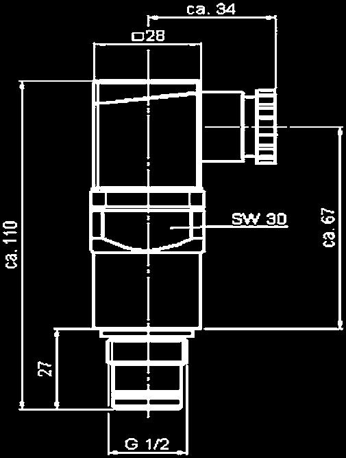
151 4. Specifications PVD x B.x PVD x C.x Type of indication Weight Cracking pressure or indication range Perm. operating pressure Perm. temperature range Thread Max. torque value Switching type Max. switching voltage Electrical connection Max. switching voltage at resistive load Switching capacity Protection class acc. DIN Order example Type of indication Visual, red/green band Automatic reset 110 g 1 bar ± 10% 3 bar ± 10% 1.5 bar ± 10% 5 bar ± 10% 2 bar ± 10% 8 bar ± 10% 420 bar -20 C to +100 C G ½ 100 Nm PVD 2 B.1 Electrical switch Weight Cracking pressure or indication range Perm. operating pressure Perm. temperature range Thread Max. torque value Switching type Max. switching voltage Electrical connection Max. switching voltage at resistive load Switching capacity Protection class acc. DIN Order example 220 g 1 bar ± 10% 3 bar ± 10% 1.5 bar ± 10% 5 bar ± 10% 2 bar ± 10% 8 bar ± 10% 420 bar -20 C to +100 C G ½ 100 Nm N/C or N/O (change-over contacts) 230 V Male connection M20x1.5 acc. EN Female connector acc. DIN W = 100 VA ~ Ohmic 3 A at 24 V = Ohmic 0.03 to 5 A at max. 230 V ~ IP 65 (only if the connector is wired and fitted correctly) PVD 5 C.0 M20x1.5 gem. EN PVD x D.x /-L... Type of indication Visual indicator and electrical switch Weight Cracking pressure or indication range Perm. operating pressure Perm. temperature range Thread Max. torque value Switching type Max. switching voltage Electrical connection Max. switching voltage at resistive load Switching capacity Protection class acc. DIN Order example 250 g 1 bar ± 10% 3 bar ± 10% 1.5 bar ± 10% 5 bar ± 10% 2 bar ± 10% 8 bar ± 10% 420 bar -20 C to +100 C G ½ 100 Nm N/C or N/O (change-over contacts) 24, 48, 110, 230 V depending on the light insert Male connection M20x1.5 acc. EN Female connector acc. DIN W = 100 VA ~ Ohmic 3 A at 24 V = Ohmic 0.03 to 5 A at max. 230 V ~ IP 65 (only if the connector is wired and fitted correctly) PVD 2 D.0 /-L24 E /


152 V01 x VZ.x Type of indication Weight Cracking pressure or indication range Perm. operating pressure Perm. temperature range Thread Max. torque value Switching type Max. switching voltage Electrical connection Max. switching voltage at resistive load Switching capacity Protection class acc. DIN Order example Differential pressure gauge DS11 Type of indication Weight Cracking pressure or indication range Perm. operating pressure Perm. temperature range Thread Max. torque value Switching type Max. switching voltage Electrical connection Visual/analogue indicator and 1 electrical switching contact at 75% and 100% of the cracking pressure 650 g 0.8 bar ± 10% 2.0 bar ± 10% 4.3 bar ± 10% 160 bar -20 C to +100 C G ¼ 75% - N/O contact 100% - N/C contact 250 V Threaded connection M20x1.5 acc. EN % contact 100% contact 120 W = 30 W = 120 VA ~ 60 VA ~ Ohmic 2.5 A at 24 V = Ohmic 1 A at 250 V ~ IP 55 V01 2 VZ.0 2 microswitches, 1-pole change-over contacts, can be adjusted manually to recommended set values kg bar 0-4 bar on request 25 bar, 40 bar on request -10 C to +100 C G ¼ Change-over contacts U~max = 250 V AC U~max = 30 V DC Hard-wired numbered cable, cable connector, 7 pole plug-in connection Max. switching voltage Imax = 5 A, Pmax. = 250VA at resistive load Imax = 0.4 A, Pmax. = 10 W Switching capacity Protection class to DIN IP 55 Order numbers Pressure chamber in aluminium: Pressure chamber in stainless steel: Note The information in this brochure relates to the operating conditions and applications described. For applications or operating conditions not described, please contact the relevant technical department. Subject to technical modifications. E / Process Technology GmbH Am Wrangelflöz 1 D Neunkirchen Tel.: +49 (0) Fax: +49 (0) Internet: prozess-technik@hydac.com

 which are joined together using a sintering process.")

153 Filter Element Technology 1. General The product range comprises components for the filtration of low and high viscosity fluids for the process engineering, chemical and plastic processing industry, e.g. acids, alkalis, water, superheated steam/gas and polymer melts. 2. Technology Different filter media (Chemicron metal fibre and wire mesh) or a combination of these are used for the filtration process. Chemicron metal fibres consist of a multitude of very fine and evenly distributed stainless steel fibres (316L, special materials on request) which are joined together using a sintering process. The essential advantages of this highly porous filter material over other materials, such as wire mesh and sintered metals, are the high contamination retention capacity and the high porosities up to 90 %. 3. Application A specialist area of fluid filtration is in the production and processing of plastics. In addition to the contamination brought in from outside and present in the manufacture of raw materials, the presence of gels often causes further problems in product quality assurance. Filtration using special filter elements Application schematic for production of pellets, fibres and films Pellets Fibres Reactor Gear pump Plastic extruder Filter with Chemicron (metal fibre), in filtration ratings of 1 and 100 µm absolute, has proven most effective in this field. The filter elements are supplied in pleated form as standard or special elements. Filter Granulator Pellets Spinning nozzles Fibres Films Filter Nozzles Films Plastic extruder Chemicron metal fibre For further information on element technology from Hydac Process Technology, please contact our technical sales department. NOTE The information in this brochure relates to the operating conditions and applications described. For applications or operating conditions not described, please contact the relevant technical department. Subject to technical modifications. Process Technology GmbH Am Wrangelflöz 1 D Neunkirchen Tel.: +49 (0) Fax: +49 (0) Internet: prozess-technik@hydac.com E /
154 E /
155 Filter Questionnaire Company: Name: Address: Telephone: Fax: Mobile: Description of application (if necessary, enclose sketches): Fluid type: Medium Viscosity cst. Type of contamination Contamination content mg/l Fluid group (PED 97/23/EC) Group 1 c Group 2 c (hazardous) (non-hazardous) Safety data sheet / CAS No.: (only if applicable) Operating specifications: P1: Operating pressure/ Pressure at inlet bar P2: Pressure at outlet*** bar P3: Backflushing line pressure*** bar Operating temperature* C Flow rate m³/h Design data: Design pressure bar Design temperature * C Flow rate m³/h Filtration rating μm Connection inlet/outlet Materials Required filter type Single filter c Duplex filter c Automatic filter c Filter material Disposable c Re-usable c Clogging indicator** Visual c Visualelectrical Type of control*** Electropneumatic c Electrical c c Electrical only c Pneumatic only Compressed air*** Yes c No c if yes, please indicate: bar Power supply voltage*** V Hz Neutral Yes c No c Required approvals/certificates Quantity c * If the maximum operating temperature of the fluid exceeds its boiling point, please contact Head Office ** Not required when using an automatic backflushing filter *** This information is only required when using an automatic backflushing filter D E / XX.0/
156 ATEX Check List Customer: Project: Which product is to be used? Production Groups According to EC Directive 94 / 9 / EC, Appendix I Group I Mines, methane and/or combustible dust Group II Potentially explosive atmosphere of gas/air, dust/air mixtures, vapours or mists Category M Category 1 Category 2 Category G (Gas) (Zone 0) D (Dust) (Zone 20) G (Gas) (Zone 1) D (Dust) (Zone 21) G (Gas) (Zone 2) D (Dust) (Zone 22) For equipment with a very high level of safety. Continued operation under occasional malfunctions. For equipment with a high level of safety. Intended to be de-energized in event of explosive atmosphere. For equipment with a very high level of safety. Designed for environments where a potentially explosive atmosphere is to be always or frequently expected. For equipment with a high level of safety. Designed for environments where a potentially explosive atmosphere is to be expected. For equipment with a normal level of safety. Designed for environments where a potentially explosive atmosphere is rarely expected and then only for a short time. Annex II / No or Annex II / No. 2.1 Annex II / No. 2.2 Annex II / No. 2.3 Temperature class max. surface temperature in C T1 450 T2 300 T3 200 T4 135 T5 100 T6 85 Types of ignition protection (only for electrical units) without ignition protection d flameproof enclosure i intrinsic safety m encapsulation e increased safety p pressurized encapsulation q powder filling o oil immersion s special protection n various protection principles for Zone 2 E /03.11 Note The information in this brochure relates to the operating conditions and applications described. For applications or operating conditions not described, please contact the relevant technical department. Subject to technical modifications. Process Technology GmbH Am Wrangelflöz 1 D Neunkirchen Tel.: +49 (0) Fax: +49 (0) Internet: prozess-technik@hydac.com 156
157 D E / XX.0/
158 E /
159 AUS BG BLR BR CDN CH CZ (Slovenia, Croatia, Bosnia- Herzegovina, Serbia and Montenegro, Macedonia) HYDAC Hydraulik Ges. m.b.h. Industriestr. 3 A-4066 Pasching Tel.: (0043) / Fax: (0043) / info@hydac.at AUSTRALIA HYDAC Pty. Ltd. 111 Dohertys Road, Altona North. AUS-Vic postal address: P.O. Box 224, Altona North. AUS-Vic Tel.: (0061) 3 / Fax: (0061) 3 / info@hydac.com.au A ÖSTERREICH HYDAC sprl Overhaemlaan 33 B-3700 Tongeren Tel.: (0032) Fax: (0032) B BELGIQUE BULGARIA HYDAC EOOD Business Center Iskar Yug München-Str. 14 BG-1528 Sofia Tel.: (00359) , (00359) Fax: (00359) office@hydac.bg Internet: BELARUS HYDAC Belarus Timirjazeva 65a, biura BY Minsk Belarus Tel.: (00375) Fax: (00375) info@hydac.com.by Internet: BRASIL HYDAC Limitada Rua Fukutaro Yida, 225 CEP BR-Sao Bernardo do Campo-SP Tel. (0055) 11/ Fax: (0055) 11/ hydac@hydac.com.br CANADA HYDAC Corporation 14 Federal Road Welland, Ontario L3B 3P2 Tel.: (001) 905 / Fax: (001) 905 / Internet: sales@hydac.ca SCHWEIZ HYDAC S.A. Zona Industriale 3 CH-6805 Mezzovico Tel.: (0041) 91 / Fax: (0041) 91 / info.coolingsystems@hydac.ch Internet: HYDAC AG Allmendstr. 11 CH-6312 Steinhausen/Zug Tel.: (0041) 41 / Fax: (0041) 41 / hydac-engineering-ag@hydac.com Internet: ČESKÁ REPUBLIKA HYDAC S.R.O. Kanadska 794 CZ Planá nad Luznici Tel.: (00420) 381/ Fax: (00420) 381/ hydac@hydac.cz HYDAC-Büro Berlin IBH Ingenieurbüro und Handelsvertretung Hammer GmbH Kaiser-Wilhelm-Str. 17 D Berlin Tel.: 0 30 / Fax: 0 30 / HYDAC-Büro Südost Wiesestr. 189 D Gera Tel.: / Fax: / D DEUTSCHLAND HYDAC-Büro Nordost Pankstraße 8-10 (Gebäude H) D Berlin Tel.: 0 30 / Fax: 0 30 / HYDAC-Büro Hamburg Mühlenweg D Norderstedt Tel.: 040 / Fax: 040 / HYDAC-Büro Nord Kirchhorster Str. 39 D Hannover Tel.: / Fax: / HYDAC-Büro West Riedinger Str. 6 D Essen Tel.: / Fax: / HYDAC-Büro Mitte Dieselstr. 9 D Darmstadt Tel.: / Fax: / HYDAC-Büro Südwest Rehgrabenstr. 3 D Dudweiler Tel.: / Fax: / HYDAC-Büro Süd Dieselstraße 30 D Aspach Tel.: / Fax: / HYDAC-Büro München Danziger Str. 21 D Gröbenzell Tel.: / Fax: / DK ET F GB GR HK I IND J L MAL HYDAC-Büro Nürnberg Ginsterweg 4 D Leinburg Tel.: / Fax: / DENMARK HYDAC A/S Havretoften 5 DK-5550 Langeskov Tel.: (0045) Fax: (0045) hydac@hydac.dk HYDAC TECHNOLOGY SL Capcir 5, P.O. Box 162 E Castellar del Valles Tel.: (0034) 93 / Fax: (0034) 93 / E ESPAÑA EGYPT Yasser Fahmy Hydraulic Eng Saudi Building, Kobba P.O. Box 6550 Sawah ET-Cairo Tel.: (0020) 2 / , , Fax: (0020) 2 / yasserf@yf-hydraulic.eg FRANCE HYDAC S.à.r.l. Technopôle Forbach Sud BP F Forbach Cedex Tel.: (0033) Fax: (0033) (siège): hydac_france@hydac.com (agence Nord-Est): ag_nest@hydac.com AGENCE DE PARIS: Tel.: (0033) ag_paris@hydac.com AGENCE DE LYON: Tel.: (0033) ag_lyon@hydac.com AGENCE DE BORDEAUX: Tel.: (0033) HYDAC OY Kisällintie 5 FI Vantaa Tel.: (00358) Fax: (00358) hydac@hydac.fi FI FINLAND GREAT BRITAIN HYDAC TECHNOLOGY Limited De Havilland Way, Windrush Park OX29 0YG Tel.: (0044) Fax: (0044) Internet: info@hydac.co.uk GREECE Delta-P Technologies Ltd. 2, Grevenon Str. GR Athens Tel.: (0030) Fax: (0030) delta_pi@otenet.gr HYDAC Hidraulika és Szüréstechnika Kft. Jász u.152/a H-1131 Budapest Tel.: (0036) Fax: (0036) hydac@axelero.hu H MAGYARORSZÁG HONG KONG Hydac Technology (Hongkong) Ltd. Unit 02 E, 10/F East Ocean Centre No. 98 Granvilla Road Tsim Sha Tsui, Kln. Hong Kong Tel.: (00852) Fax: (00852) ITALIA HYDAC S.p.A. Via Archimede, 76 I Agrate Brianza Tel.: (0039) 039 / Fax: (0039) 039 / Internet: hydac@hydac.it INDIA HYDAC (India) Pvt. Ltd. A-58 TTC Industrial Area MIDC, Mahape IND-Navi Mumbai Tel. (0091) /02/03/04/ /54/55 Fax: (0091) k.venkat@hydacindia.com Iran Hydraulic Systems Co. Ltd. 310, Mirdamad Ave. Bazar Bozorg Mirdamad P.O. Box IR-Teheran Tel.: (0098) 21 / Fax: (0098) 21 / IR IRAN JAPAN HYDAC Co. Ltd. KSK Bldg. West-9F Hatchobori, Chuo-ku Tokyo, Japan Tel.: (0081) 3 / Fax: (0081) 3 / LUXEMBURG FRIEDERICH-HYDROPART S.A.R.L. Route d Esch, C.P. 38 L-3801 Schifflange Tel.: (00352) Fax: (00352) MALAYSIA HYDAC Technology Sdn Bhd 28, Jalan PJU 3/44 Sunway Damansara MAL Petaling Jaya Tel.: (0060) 3 / Fax: (0060) 3 / common@hydac.com.my MEX NL NZ PL PRC RUS RA RCH MEXICO HYDAC International SA de CV Pirul, Los Reyes Ixtacala Tlalnepantla (Edo. de Mexico) MEXICO Tel.: (0052) 555 / Fax: (0052) 555 / HYDAC AS Postboks 657 N-1401 SKI Tel.: (0047) Fax: (0047) firmapost@hydac.no N NORGE NETHERLANDS HYDAC B.V. Vossenbeemd 109 NL-5705 CL Helmond Tel.: (0031) 492 / Fax: (0031) 492 / info@hydac.nl NEW ZEALAND HYDAC Ltd. Unit 14, 13 Highbrook Drive East Tamaki NZ-Auckland Tel.: (0064) Fax: (0064) Gustavo Cudell Lda. Rua Eng. Ferreira Dias, 954 P Porto Tel.: (00351) 22 / Fax: (00351) 22 / Internet: info-es@cudell.pt MOVICONTROL S.A. Rua Prof. Henrique de Barros 5 B Prior Velho P-1801 Lisboa Codex Tel.: (00351) Fax: (00351) Internet: geral@movicontrol.pt P PORTUGAL POLSKA HYDAC Sp. z o.o. ul. Reymonta 17 PL Mikołȯw Tel.: (0048) 32 / Fax: (0048) 32 / info@hydac.com.pl CHINA HYDAC Technology (Shanghai) Ltd. 28 Zhongpin Lu Shanghai Minhang Economic & Technological Development Zone P.R.C.-Shanghai Tel.: (0086) 21 / Fax: (0086) 21 / hydacsh@hydac.com.cn RUSSIA HYDAC International ul. 4-ya Magistralnaya, 5, office 31 RUS Moscow Tel.: (007) Fax: (007) info@hydac.com.ru Internet: Technical Office St. Petersburg Obvodnyi chanel emb., 138, blok 101, of 401 RUS St. Petersburg Tel.: (007) Fax: (007) petersb@hydac.com.ru Technical Office Chelyabinsk Pr-t Pobedy, 100 RUS Chelyabinsk Tel.: (007) , Fax: (007) chel@hydac.com.ru Technical Office Novokuznetsk ul. Nevskogo, 1, office 300 RUS Novokuznetsk Kemerovskaya Obl. Tel.: (007) Tel./Fax: (007) novokuz@hydac.com.ru Technical Office Ulyanovsk ul. Efremova, 29, office 418 RUS Ulyanovsk Tel.: (007) Fax: (007) uljan@hydac.com.ru ARGENTINA HYDAC TECHNOLOGY ARGENTINA S.R.L. Av. Belgrano 2729 (B1611DVG) Don Torcuato RA-Tigre / Buenos Aires Tel.:(0054) /0770/2323 Celular argentina@hydac.com CHILE MAURICIO HOCHSCHILD S.A.I.C. Avenida Senador Jaime Guzman 3535 RCH-Renca-Santiago Tel.: (0056) 2 / , Fax: (0056) 2 / Hydac Technology Pte Ltd Rep Office Indonesia Perwate Tower - CBD Pluit 6th Floor, Suite A Jl. Pluit Selatan Raya RI INDONESIA Tel.: (006221) Fax: (006221) info@hydac.co.id Internet: ROK ROM SGP SK SL T TR TW UKR USA VN ZA KOREA HYDAC Duwon Co. 4 th floor Wonwook Bldg Bangbae, Seocho ROK-Seoul Tel.: (0082) 2/ Fax: (0082) 2/ johnkim@hydackorea.co.kr ROMANIA HYDAC SRL Str. Vanatori Nr. 5 B RO Ploiesti Tel.: (0040) Fax: (0040) hydac@hydac.ro HYDAC Fluidteknik AB Domnarvsgatan 29 S Spånga Tel.: (0046) 8 / Fax: (0046) 8 / Internet: hydac@hydac.se S SVERIGE SINGAPORE Hydac Technology Pte Ltd. 2A Second Chin Bee Road Singapore Tel.: (0065) Fax: (0065) SLOVAKIA HYDAC, s.r.o. Schmidtova 14 SK Martin Tel.: (00421) , Fax: (00421) hydac@hydac.sk SLOVENIA HYDAC d.o.o. Slovenia Zagrebska c. 20 SL-2000 Maribor Tel.: (00386) 2 / Fax: (00386) 2 / hydac.slovenia@hydac.si THAILAND Aerofluid Co. Ltd. 169/4, 169/5 Moo 1 Rangsit-Nakhonnayok Rd. Lampakkud, Thanyaburi Patumthanee Tel.: (0066) (30 lines) Fax: (0066) info@aerofluid.com TURKEY HYDAC Ltd. Şti. Namık Kemal Mahallesi Adile Naşit Bulvarı 174 Sok. No.9 TR-Esenyurt - İstanbul Tel.: (0090) 212 / Fax: (0090) 212 / info@hydac.com.tr TAIWAN HYDAC Technology Ltd. No. 6 Shuyi Road, South District TW-Taichung City/Taiwan Tel.: (00886) 4 / Fax: (00886) 4 / sales@hydac.com.tw UKRAINE HYDAC Ukraine ul. B. Chmelniykogo 55, office 811 UA Kiev Tel.: (00380) Fax: (00380) info@hydac.com.ua Internet: USA HYDAC TECHNOLOGY CORPORATION Hydraulic Division 445 Windy Point Drive USA-Glendale Heights, IL Tel.: (001) Fax: (001) Internet: sales@hydacusa.com VIETNAM HYDAC International E-Town Building, Mezzanine Floor Executive office, Room 7, 364, Cong Hoa Street, Tan Binh District VN-Ho Chi Minh City Tel.: (00848) Etx: 215 & 214 Fax: (00848) SOUTH-AFRICA (Namibia, Zimbabwe) HYDAC Technology Pty Ltd. 165 Van der Bijl Street Edenvale 1614 ZA-Johannesburg Tel.: (0027) Fax: (0027) hydacza@hydac.com Hytec S.A. P.O. Box Koornhof Str. Meadowdale ZA-Edenvale 1610 Tel.: (0027) 11 / Fax: (0027) 11 / olivern@hytec.co.za 96 D E / XX.0/


6897-509-1241")
160 E / Brochure: Cooling Systems Catalogue: Electronics Catalogue: Accessories Brochure: Compact Hydraulics Catalogue: Fluid Service Catalogue: Process Technology Catalogue: Filter Technology Catalogue: Storage Technology Global Presence. Local expertise. HYDAC Headquarters HYDAC Companies HYDAC Distributors and Service Partners Head Office HYDAC Process Technology GmbH Industriegebiet Grube König Am Wrangelflöz Neunkirchen Germany Phone: +49 (0) Fax: +49 (0) Internet: prozess-technik@hydac.com D /03.11
Backflushing Filter AutoFilt RF3
 Backflushing Filter AutoFilt C 2,5 4 6 8 1. TECHNICAL SPECIFICATIONS 1.1 GENERAL The automatic back-flushing filter AutoFilt is a self-cleaning system for extracting particles from lowviscosity fluids.
Backflushing Filter AutoFilt RF4
 1. Technical Specifications 1.1 General The automatic backflushing AutoFilt RF4 is a selfcleaning system for extracting particles from low viscosity fluids. Its robust construction and automatic backflushing
Automatic back-flushing filter AutoFilt RF4
 Automatic back-flushing filter AutoFilt RF4 RF4-1 RF4-2 Specifications Nominal size: G1 G 1½ Q max: 220 l/min p max: 16 bar Filtration ratings: 30 1000 µm 1. GENERAL Product description Self-cleaning automatic
Automatic Back-Flushing Filter for Process Technology AutoFilt RF3.
 Automatic Back-Flushing Filter for Process Technology AutoFilt RF3. AutoFilt RF3: So automatic, The Challenge Particle contamination in process water and other operating fluids accelerates the rate of
Process Multi-Rheo Filter PMRF
 Process Multi-Rheo Filter PMRF PMRF-1 PMRF-2 PMRF-3 PMRF-5 PMRF-6 PMRF-7 1. Technical Specifications 1.1 General The filter series PMRF (for duplex filters see PMRFD) Process Multi- Rheo Filter completes
Process screen basket filter PRFS
 Process screen basket filter PRFS PRFS- PRFS- PRFS- PRFS- PRFS- PRFS- 130x 250x 520x 650x 1500x 2500x Nominal size: Q s max: p s max: Filtration ratings: Specifications DN 50 DN 700 3600 m³/h 16 bar 25
Process Inline Filter Protective filter PLF2-9HF
 Process Inline Filter Protective filter PLF2-9HF Specifications Nominal size: DN 300 - DN 600 Q s max: 3000 m 3 /h p s max: 16 bar Filtration ratings: 1-90 µm 1. GENERAL Product description Protective
AutoFilt RF3 Automatic Self-Cleaning Filter
 AutoFilt RF3 Automatic Self-Cleaning Filter DESIGN The AutoFilt RF3 is an automatic self-cleaning filtration system designed for continuous maintenance-free filtration for all major manufacturing and processing
AutoFilt RF3 Automatic Self-Cleaning Filter
 AutoFilt RF3 Automatic Self-Cleaning Filter DESIGN COST EFFECTIVENESS TECHNICAL DATA Courtesy of CMA/Flodyne/Hydradyne Motion Control Hydraulic Pneumatic Electrical Mechanical (800) 426-5480 www.cmafh.com
HYDAC AutoFilt Automatic Filters Product Overview
 HYDAC AutoFilt Automatic Filters Product Overview Your Partner for Expertise in Automatic Filtration The HYDAC AutoFilt Concept Challenge Particle contamination in process water and other operating fluids
Inline Filters for Process Technology
 Inline Filters for Process Technology Inline Filters for Every Process. HYDAC inline filters feature high filtration capacity and easy handling and therefore contribute to safe and economical system operation.
Process Inline Filter PLF1
 Process Inline Filter PLF1 10 bar 16 bar Specifications Nominal size: DN 50 DN 150 Q s max: 200 m 3 /h p s max: 16 bar Filtration ratings: 1 90 µm 1. GENERAL Product description Continuous separation of
Process Inline Filter Medium / High Pressure PFM / PFH
 Process Inline Filter Medium / High Pressure PFM / PFH PFx-0 PFx-1 PFx-2 PFx-3 Specifications Connection: G 1 Q S max: 8 m 3 /h p S max: 100 bar Filtration ratings: 1 2000 µm 1. GENERAL Product description
HYDAC Process Technology Water Filtration Product Overview
 HYDAC Process Technology Water Product Overview Solutions for Water Filtr ation in Different Applications Offshore wind power Marine Oil platforms / FPSO Power plant Desalination plants Refinery Chemical
Automatic Back-Flushing Filter AutoFilt RF9.
 Automatic Back-Flushing Filter AutoFilt RF9. AutoFilt RF9 Clearing the Way. The Challenge: In response to the Tier III standard which will come into effect in 2016, the International Maritime Organization
Automatic filter AF 172 G
 Automatic filter AF 172 G with external pressure cleaning and integrated cyclone effect Connection sizes: DN 40/G1 1/2, cast design 1. Short description MAHLE automatic backflush filters are suitable for
Automatic filter AF 112 G
 Automatic filter AF 112 G Cast design with internal pressure cleaning and integrated cyclone effect Connection size: flange DN 40 or G1 1/2 1 Short description MAHLE automatic backflush filters are suitable
Automatic filter AF 173 G
 Automatic filter AF 7 G with external pressure cleaning and integrated cyclone effect Connection sizes: G, screw-in flange DN 0 and DN, cast design Short description MAHLE automatic backflush filters are
Automatic filter AF 113 G
 Automatic filter AF 113 G Cast design with internal pressure cleaning and integrated cyclone effect Connection sizes: G2, screw in flange DN 50 and DN 65 1 Short description MAHLE automatic backflush filters
Filter module AF Features. MAHLE Industrialfiltration is now Filtration Group. For more information, visit
 MAHLE Industrialfiltration is now Filtration Group. For more information, visit www.filtrationgroup.com Filter module AF 43 Nominal pressure 16 bar, nominal temperature 180 C; nominal width DN 80 to DN
Automatic filter AF 113 G
 Automatic filter AF G Cast design with internal pressure cleaning and integrated cyclone effect Connection sizes: G, screw in flange DN 0 and DN Short description MAHLE automatic backflush filters are
Automatic filter AF 153 G
 Automatic filter AF 153 G with scraper and external pressure cleaning Connection sizes: DN 50/G2, cast stainless steel 1 Features MAHLE automatic backflush filters are suitable for all applications where
Automatic filter AF 173 G
 Automatic filter AF 7 G with external pressure cleaning and integrated cyclone effect Connection size DN 0/G, cast stainless steel Short description MAHLE automatic backflush filters are suitable for all
Automatic metal-edge filter AF 73 G/AF 93 G
 Automatic metal-edge filter AF 73 G/AF 93 G with radial scraper cleaning Connection size G2, screw-in flange DN 50 and DN 65 1 Features MAHLE automatic metal-edge filters are suitable for all applications
Automatic metal-edge filter AF 75 S / AF 95 S
 Automatic metal-edge filter AF 75 S / AF 95 S with radial scraper cleaning housing in welded design, optionally with cyclone effect Connection size DN 150, DN 200, DN 250 others upon request 1. Features
Automatic metal-edge filters AF 72 G
 Automatic metal-edge filters AF 72 G with radial scraper cleaning Connection size G1 1/2, flange DN 40 1 Short description MAHLE automatic metal-edge filters are suitable for all applications where low
Industrial automatic self-cleaning filters made in stainless steel AISI 316
 Industrial automatic self-cleaning filters made in stainless steel AISI 316 FilBlue Introduction The automatic industrial selfcleaning filters are designed to remove all suspended solids from surface water
PRODUCT BROCHURE AUTOMATIC AND MANUAL. filtration systems BOLLFILTER UK LIMITED
 PRODUCT BROCHURE AUTOMATIC AND MANUAL filtration systems UK LIMITED EFFICIENT, LOW MAINTENANCE filtration systems The Boll & Kirch Product Range incorporates a comprehensive selection of quality filters
MAHLE Automatic Filter Series R8-30W
 MAHLE Automatic Filter Series R8-30W With internal pressure segment cleaning, rated pressure to 150 psi Connection Sizes: ANSI 8" to ANSI 20", welded design 1. Features Powerful, fully automatic filtration
Change-Over Inline Filter RFLD Welded Version
 Change-Over Inline Filter RFLD Welded Version up to 15000 l/min, up to 16 bar RFLD 1300 CAS to RFLD 15000 CBW 1. TECHNICAL SPECIFICATIONS 1.1 FILTER HOUSING Construction The filter housings are designed
Change-Over Pressure Filter DFDK
 Change-Over Pressure Filter up to 2500 l/min, up to 315 bar 30 60 110 140 160 240 280 330 500 660 1.x 660 2.x 990 2.x 1320 2.x 1320 3.x 2640 3.x 3960 3.x 1. TECHNiCAL SPECIFICATIONS 1.1 FILTER HOUSING
HYDAC Process Technology Gas Filters Product Overview
 HYDAC Process Technology Gas Filters Product Overview HYDAC Gas Filtration Service-life Insurance for your System The areas of application Media to be filtered Components to be protected Worldwide and
KWF KRONEFILTER.COM SOLUTIONS IN FILT RATION. Single filter. Application areas. Approvals PN DN ANSI ½ 40 JIS GOST
 KWF Single filter Steel, stainless steel, plastic, GRP PN 10 64 DN 15 1000 ANSI ½ 40 JIS 15 1000 GOST 15 1000 ISO 9001:2015 Application areas The KWF single filter is a versatile implementation filter
Proportional Pressure Reducing Valve PDM08130
 Proportional Pressure Reducing Valve PDM08130 up to 80 bar up to 10 l/min Cartridge valves Control electronics Connection housings 486 1. DESCRIPTION 1.1. GENERAL According to DIN-ISO 1219, HYDAC proportional
Automatic metal-edge filter AF 71 G
 Automatic metal-edge filter AF 71 G with radial scraper cleaning Connection size G1 1 Features MAHLE automatic metal-edge filters are suitable for all applications where low or high-viscosity liquids or
Profluid and Gap-type tube filters. Automatic filters
 and Gap-type tube filters Automatic filters and Gap-type tube filters the efficient answer for multi-purpose applications Identical technology two different cleaning principles Automatic filters such as
Return Line Filter RF
 Return Line Filter up to 15000 l/min, up to 25 bar 30 60 110 160 240 330 450 580 660 950 1300 2500 4000 5200 6500-7800 15000 1. TECHNiCAL SPECIFICATIONS 1.1 FILTER HOUSING Construction The filter housings
Inline Filters NF. Flow rates up to 3,500 l/min Pressure range 25 bar Material: Aluminium / Aluminium-Cast Iron
 NF filters are designed for inline mounting and as tank-top mounted return line filters. These filters can also be used on filling, flushing and off-line units. Inline Filters NF Flow rates up to 3,500
modern, unique, versatile
 The BOLLFILTER TYPE BFD modern, unique, versatile THE TASK Efficiency, profitability and environmental sustainability Efficiency, profitability and environmental sustainability are increasingly setting
Inline Filter RFL. Cast version Volume rates up to 1300 l/min* Pressure range 25/40 bar
 RFL inline filters are designed for inline mounting in hydraulic and lubrication systems. Inline Filter RFL Cast version Volume rates up to 1300 l/min* Pressure range 25/40 bar * For larger flow rates,
Pressure Filter DF...K P, DF...M P, Flange Mounted
 Pressure Filter, DF...M P, Flange Mounted up to 550 l/min, up to 260 bar DF...M P 330...1.X 160 240 280 500...1.X 660...1.X 660...2.X 990...2.X 1320...2.X 660...3.X 990...3.X 1320...3.X 1. TECHNICAL SPECIFICATIONS
MAHLE Industrial Filters. Dust Filter Equipment
 MAHLE Industrial Filters Dust Filter Equipment Pioneering systems, modules and components of the highest precision and quality for engines and vehicles as well as for industrial applications that s what
ACOUSTIC CLEANING SYSTEMS. Information Brochure.
 ACOUSTIC CLEANING SYSTEMS Information Brochure www.aw-akustik.de Introduction to acoustic cleaning The operation principle of acoustic cleaning is based on high-energy sound waves generating pressure differences
Pressure Filter DF Pressure Filter for Reversible Oil Flow DFF/DFFX
 Pressure Filter DF Pressure Filter for Reversible Oil Flow DFF/DFFX up to 2000 l/min, up to 420 bar DF/DFF...1.X/2.X 30 60 110 140 160 240 280 330 500 660 990 1320 1500 2000 3000 4000 DF...3.X DFFX...1.X/2.X
Inline Filter RFLD. Change-Over. Cast Version Flow Rates up to 1300 l/min* Pressure Range 25/40/64 bar With Ball Change-Over Valve E /01.
 Change-Over Inline Filter RFLD Cast Version Flow Rates up to 3 l/min* Pressure Range 25/4/64 bar With Ball Change-Over Valve * For higher flow rates, please refer to brochure RFLD Welded Version E 7.9.2/.4
Return Line Filter RFM with 4-Hole Mounting
 Return Line Filter with 4-Hole Mounting Tank-top mounted versions: up to 850 l/min, up to 10 bar 75 90 150 165 185 210 270 330 500 600 661 851 1. TECHNiCAL SPECIFICATIONS 1.1 FILTER HOUSING Construction
Inline filters NF NF 1350 NF 330 NF 750 NF 500 NF FILTER SPECIFICATIONS Nominal pressure
 Inline filters up to 3500 l/min, up to 25 bar 160 240 280 330 500 750 950 1350 2650 on request 1310 2.x on request 2610 2.x 1340 2640 5240 7840 10440 1. TECHNICAL SPECIFICATIONS 1.1 FILTER HOUSING Construction
The JET Filter. Scope of Delivery. patented. The New Definition of Purity for Your Medium. Our Filter Systems Protect
 GB JET Filter The New Definition of Purity for Your Medium Our Filter Systems Protect The JET Filter Cooling Water River Water Plate Heat Exchangers Spray Nozzles Sea Water Sinter and Scale Separation
Mounting and Operating Instructions EB 5894 EN. Electric control valves with jet pump. Flanged version of valve with jet pump
 Electric control valves with jet pump Type 3267/5824, Type 3267/5825, Type 3267/3374, Type 3267/3274 Pneumatic control valves with jet pump Type 3267-1, Type 3267-7 Flanged version of valve with jet pump
HAWLE-AIR RELEASE VALVES
 HAWLE-AIR RELEASE VALVES HAWLE-AIR RELEASE VALVES Contents: Dimensions of Air Release Valve Page 2 Why use Air Release Valves? Page 3 Application: Potable water Air Release Valves, DN 1" - DN 2" Page 4
22PD/32PD Series High Pressure Duplex Filters Max 260 l/min bar
 / Series Max 26 l/min - 21 bar A duplex design with a wide application capability Designed to offer continuous operation during element change The / Series utilizes a duplex design with integrated balancing
Pressure Filter for Manifold Mounting DFP and for Reversible Flow DFPF
 Pressure Filter for Manifold Mounting DFP and for Reversible Flow DFPF up to 600 l/min, up to 315 bar 60 110 140 160 240 280 330 500 660 1.X 660 2.X 990 1320 1. TECHNiCAL SPECIFICATIONS 1.1 FILTER HOUSING
Low / Medium Pressure Duplex Filter Inline mounting. Type : 40/160-LD/LDN. Filters. Accumulators. Hydraulic Symbol. Technical Data
 Filters. Accumulators Low / Medium Pressure Duplex Filter Inline mounting Type : 0/60LD/LDN Hydraulic Symbol Technical Data Material of Construction Head : GGG50. Bowl : Carbon Steel. Seals : Nitrile /
Return Line Filter RFM with 4-Hole Mounting
 Return Line Filter with 4-Hole Mounting Tank-top mounted versions: up to 850 l/min, up to 10 bar 75 90 150 165 185 195 210 270 330 500 600 661 851 1. TECHNICAL SPECIFICATIONS 1.1 FILTER HOUSING Construction
HYDAC Quality for Pall Housings: Ecomicron 2-fit.
 HYDAC Quality for Pall Housings: Ecomicron 2-fit. Your Reliable Partner for Complete Fluid Management. HYDAC Experts for complete solutions. Numerous customers and applications are the proof of HYDAC s
herborner.x -C Technical data brochure 50 Hz
 herborner.x -C % COATING = % CORROSION! Technical data brochure z The coated pool water circulation pump with a close coupled design with heat exchanger motor: Efficient, flexible and long-lasting all
Sectional Directional Control Valve RS 220
 Sectional Directional Control Valve RS 0 RS 0 is a sectional open center valve designed for max. operating pressures up to 00 bar and max. pump flows up to 0 l/min. Technical data Pressure and flow values*
Return Line Filter HF4R up to 450 l/min, up to 10 bar
 Return Line Filter HF4R up to 450 l/min, up to 10 bar 9" 18" 27" 1. TECHNiCAL SPECIFICATIONS 1.1 FILTER HOUSING Construction The filter housings are designed in accordance with international regulations.
Air Cooler Industry AC-LN 8-14 / ACA-LN 8-11 / ACAF-LN 8-11
 Air Cooler Industry AC-LN 8-14 / ACA-LN 8-11 / ACAF-LN 8-11 Symbol General The AC-LN 8-14 air cooler series can be used in all areas where either oil or water-glycol is to be cooled with air. The coolers
Change-Over Inline Filter AFLD to API 614
 Change-Over Inline Filter to API 614 up to 17 l/min, up to 4 bar 112/ 113 122/ 123 232/ 233 242/243 332/333 52/53 542/543 882/883 142/143 272/273 1. TECHNICAL SPECIFICATIONS 1.1 FILTER HOUSING Construction
YARWAY NARVIK STANDARD DUTY A.T.-TEMP DESUPERHEATER MODEL 38/48
 Yarway covers requirements for Desuperheaters, pneumatic actuators, strainers with a wide range of models, sizes and materials to satisfy all the specifications of the power-pulp and paper industry and
Filtration and separation technology. Lenzing OptiFil Automatic backwash filter
 Filtration and separation technology Lenzing OptiFil Automatic backwash filter Lenzing OptiFil 3 Lenzing OptiFil Automatic backwash filter filtration down to 1 µm OptiFil is a fully automatic, continuous
Suction Filter SF/SFM/SFF and Suction Filter Elements S/S..
 Suction Filter /M/F and Suction Filter Elements S/S.. up to 500 l/min Filters: 60 110 160 240 330 M 330 F 400 F 500 Elements: S SH. SU. SG. 1. TECHNICAL SPECIFICATIONS 1.1 FILTER HOUSING Construction The
GSR - your partner for valve technology. Welcome to the world of valve technology. Your GSR Team
 Welcome to the world of valve technology GSR - your partner for valve technology This is the world of solenoid valves, with and without explosion protection, of external medium-controlled valves and motorised
LINEAR AND ROTATING TYPE AUTOMATIC SELF-CLEANING LIQUID FILTERS
 AUTO-LINE LINEAR AND ROTATING TYPE AUTOMATIC SELF-CLEANING LIQUID FILTERS HiFlux Auto-line is designed as a compact self-cleaning filter Its robust construction makes it suitable for industrial applications
Series RFLD Duplex In-Line Filter
 APPLICATION Series RFLD Duplex In-Line Filter Welded Pressures to 230 psi Flows to 3900 gpm HYDAC RFLD in-line filters are designed for in-line mounting and are mainly used in continuously operating systems.
Electrohydraulic Drive System EHC-A
 Electrohydraulic Drive System EHC-A HYDAC Denmark HYDAC Poland HYDAC Brazil HYDAC India HYDAC China HYDAC USA HYDAC France HYDAC Germany Your Professional Partner for Electrohydraulic Drive Systems. With
YARWAY NARVIK MODEL 88 SPID SMALL PIPE INLINE DESUPERHEATER
 A wide range of desuperheaters, pneumatic actuators, strainers to satisfy all specifications of the power, pulp and paper industry and process gas applications FEATURES Fabricated construction Special
NARVIK-YARWAY. Heavy Duty A.T. - Temp Desuperheater Model: 18/54 and 28/64
 NARVIK-YARWAY Narvik-Yarway covers requirements for Desuperheaters, pneumatic actuators, strainers with a wide range of models, sizes and materials to satisfy all the specifications of the power-pulp &
Filter elements for installation in Pall filter housings. Type 16. filter elements. Contents. Features. RE Edition:
 Filter elements for installation in Pall filter housings Type 16. filter elements RE 51464 Edition: 2014-04 Frame sizes: 6200 to 9801 Collapse pressure rating: 10 to 210 bar [145 to 3045 psi] Temperature
Return Line Filter RF
 HYDAC return line filters type RF are designed to be mounted directly on tank tops. Inline mounting is also possible. Return Line Filter RF Flow rates up to 5, l/min Pressure range up to 25 bar Material:
Return Line Filter RFM with 2-Hole Mounting
 Return Line Filter RFM with 2-Hole Mounting Tank-top versions: up to 200 l/min, up to 10 bar RFM 75 RFM 90 RFM 150 RFM 165 RFM 185 In-tank versions: up to 2,600 l/min, up to 10 bar RFM S RFM KIT RFM SET
The JET Filter. Scope of Delivery. patented. The New Definition of Purity for Your Medium. Our Filter Systems Protect
 GB JET Filter The New Definition of Purity for Your Medium Our Filter Systems Protect The JET Filter Cooling Water River Water Plate Heat Exchangers Spray Nozzles Sea Water Sinter and Scale Separation
Standard Duty A.T.S.A. - Temp Desuperheater Model 24 / 34
 Narvik-Yarway covers requirements for desuperheaters, pneumatic actuators, strainers with a wide range of models, sizes and materials to satisfy all the specifications of the power, pulp & paper industry
EN. SKF Grease Spraying System For Large Open Gears. Extend the lifetime of large gear drives
 1-4012-EN SKF Grease Spraying System For Large Open Gears Extend the lifetime of large gear drives Gear drives Large gear drives are used to transmit movement under very heavy loads. They are open gear
Off-line filter / cooler unit FGSL
 Fluidcontrol Off-line filter / cooler unit FGSL Coolers are used to stabilise the operating temperature in hydraulic and lubrication systems. This can be implemented particularly cost-efficiently by integrating
Change-Over Inline Filter RFLD Weld Version
 Change-Over Inline Filter RFLD Weld Version up to 15000 l/min, up to 16 bar RFLD 1300 CAS to RFLD 15000 CBW 1. TECHNICAL SPECIFICATIONS 1.1 FILTER HOUSING Construction The fi lter housings are designed
ERHARD is a company of. Data sheet ERHARD needle valves
 ERHARD is a company of Data sheet ERHARD needle valves ERHARD RKV needle valves The innovative needle valve with the four positive points Based on decades of experience in the design and production of
YARWAY NARVIK MODEL 33/43 STANDARD DUTY QUE-TEMP DESUPERHEATER
 Yarway covers requirements for desuperheaters, pneumatic actuators, strainers with a wide range of models, sizes and materials to satisfy all the specifications of the power-pulp and paper industry and
KAESER FILTER. KF F350 to F3360 Series Reliable purity for high flow rates Flow rate 35.4 to m³/min, Pressure 2 to 16 bar COMPRESSORS
 COMPRESSORS KAESER FILTER KF F350 to F3360 Series Reliable purity for high flow rates Flow rate 35.4 to 336.3 m³/min, Pressure 2 to 16 bar www.kaeser.com KF F350 to F3360 series Clean compressed air at
Standard Duty Que - Temp Desuperheater Model: 33 / 43
 Model: 33 / 43 Narvik-Yarway covers requirements for desuperheaters, pneumatic actuators, strainers with a wide range of models, sizes and materials to satisfy all the specifications of the power-pulp
MultiRheo Filter MRF 1/2/3/4/5/6/7
 MultiRheo Filter MRF 1/2/3/4/5/6/7 Description The MultiRheo filters of the MRF series are filter housings for use in open systems which are continually exposed to contamination. The candle filter elements
Series RFL In-Line Filter
 APPLICATION Series RFL In-Line Filter Pressures 2 bar Flows to 400 l/min HYDAC RFL In-Line Filters are designed for in-line mounting. These filters can be used in hydraulic, flushing, and for extraction
Filter Elements. for use in HYDAC filters* Pressure filter. Pressure filter. filter element (DIN 24550) elements. long seam weld
 elements. long seam weld") 1. TECHNiCAL SPECIFICATIONS 1.1 Construction As the core of the, it is the element which performs the actual filtration and/or dewatering function in the housing. They consist of several pleated filtration
1. TECHNiCAL SPECIFICATIONS 1.1 Construction As the core of the, it is the element which performs the actual filtration and/or dewatering function in the housing. They consist of several pleated filtration
12CS Series. Coreless Spin-on Filter Max. 75 l/min - 35 bar. Environmentally friendly alternative for spin-in filtration.
 12CS Series Coreless Spin-on Filter Max. 7 l/min - 3 bar Environmentally friendly alternative for spin-in filtration Lightweight, non-metallic element that can be incinerated The 12CS Series features a
EN / Modern Duplex Filters for Large Engines
 Modern Duplex Filters for Large Engines Modern Duplex Filters for Diesel, HFO and Lube Oil Filtration has a key role to play in developing and optimising heavy engine technology. The quality of the fuel
Subject title Pipeline Strainers Cover subheadline Titel_englisch.indd :42:10 Uhr
 Subject Pipeline title Strainers Cover subheadline Protecting Your Pumps, Filters, Nozzles, Flowmeters, Valves, Heat Exchangers, Condensers, Oil Burners, and Boilers From Pipeline Debris For over 75 years,
MAP Automatic Strainers In-Line Series
 MAP Automatic Strainers In-Line Series flow rate filtration degrees inlet / outlet diameters min. operating pressure up to 4.500 m 3 /h (19.800 gpm) 5.000 200 micron up to DN800 (32 ) 1 bar (15 psi) Heavy
HYDAC KineSys Motion Control Systems
 HYDAC KineSys Motion Control Systems Thermal power plants Materials handling Iron and steel industry Renewable energies Presses Plastic injection machines Your Partner for Expertise in Motion Control Solutions.
Replacement cartridge filter
 Replacement cartridge filter RE 426/0. /2 Type 7 SL 0 to 260; 7 SLS 90 to 260; SL 0 to 80 D Size 7 SL: 0 to 260 7 SLS: 90 to 260 SL: 0 to 80 D Nominal pressure 7 and/or bar Port up to G /4, SAE /2 (000
SYSTEM & PROCESS FILTERS
 SYSTEM & PROCESS FILTERS Automatic backwashing & Process filters FILTROMATIC automatic backwashing water filters Filtromatic automatic backwashing filters are designed to remove solid particles from
485 - NC NO/DA DN
 485 - NC 285 - NO/DA DN 25-100 The 485/285 diaphragm valve is particularly suitable for shutting off and regulating abrasive or dirty fluids. The new internal geometry of the body optimises fluid dynamic
High Pressure Filter Pi 4230
 High Pressure Filter 4230 Nominal pressure 315 bar (4570 psi), nominal size 160 to 400 according DIN 24550 1. Features High performance filters for modern hydraulic systems Modular system Compact design
Return line and Suction Boost Filter RKM
 Return line and Suction Boost Filter up to 850 l/min, up to 10 bar 80 100 120 151 201 251 201/-TH 300 350 400 800 1. TECHNICAL SPECIFICATIONS 1.1 FILTER HOUSING Construction The filter housings are designed
Type 6213 EV, 6281 EV
 Type 6213 EV, 6281 EV 2/2-way solenoid valve 2/2-Wege-Magnetventil Électrovanne 2/2 voies Operating Instructions Bedienungsanleitung Manuel d utilisation 1 OPERATING INSTRUCTIONS The operating instructions
High Pressure Filter Pi 4000
 High Pressure Filter Pi 4000 Nominal pressure 400 bar (5690 psi), nominal size up to 400 according DIN 24550 1. Features High performance filters for modern hydraulic systems Modular system Compact design
VARIO. VARIO Separation of fine dust particles. The VARIO series is particularly suitable for separation of fine dust.
 VARIO VARIO Separation of fine dust particles The VARIO series is particularly suitable for separation of fine dust. The VARIO units are of modular construction in order to meet different requirements,
MultiRheo Filter MRF 1/2/3/4/5/6/7
 MultiRheo Filter MRF 1/2/3/4/5/6/7 Description The MultiRheo filters of the MRF series are filter housings for use in open systems which are continually exposed to contamination. The candle filter elements
Magnetic-inductive flow meter for hazardous areas
 Magnetic-inductive flow meter for hazardous areas Technical Datasheet EPX / UMF3 high accuracy: 0.3 % of actual maintenance-free no pressure drop numerous lining materials numerous electrode materials
Spare parts list Inline filter FLND switchable
 Spare parts list Inline filter switchable to DIN 24550*, up to 400 l/min, up to 63 bar *Filters and fi lter elements also available in HYDAC dimensions 60 110 140 40 63 100 160 250 400 1. MAINTENANCE 1.1