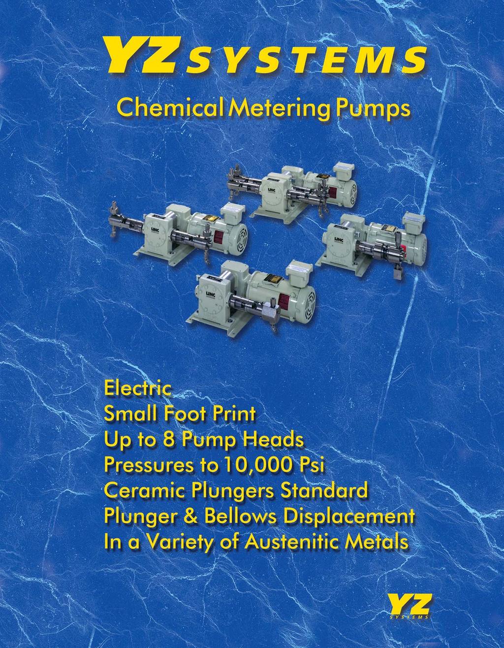
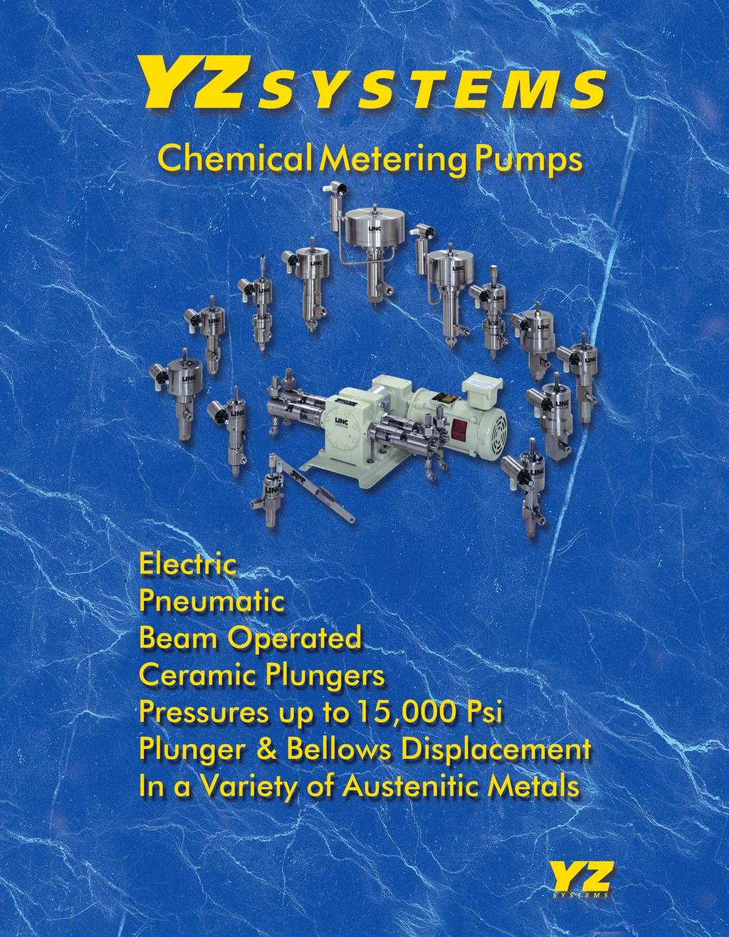
M E T E R I N G P U M P S
|
|
|
- Bernard Hubbard
- 6 years ago
- Views:
Transcription
1 T E C H N I C A L S P E C I F I C A T I O N S
2 T A B L E O F C O N T E N T S LINC Electric Pumps LINC 86 SERIES Electric Pump... 5 Plunger sizes: 1/4", 3/8", 1/2", 3/4" and 1". Pressures to 10,000 psi LINC 82 SERIES Beam Pump...29 Plunger sizes: 1/4" and 1/2". Pressures to 3,000 psi LINC Pneumatic Pumps LINC 84T-10, 11, 12, & 14 SERIES Plunger sizes: 3/16", 1/4", 1/2" and 1". Pressures to 10,000 psi LINC 84T-13 SERIES Plunger sizes: 1/2". Pressures to 9,000 psi LINC 84T-17, 18, & 20 SERIES Plunger sizes: 1", 1 1/2" and 2 1/4". Pressures to 10,000 psi LINC 85T-11 & 12 SERIES Pneumatic Bellows Plunger sizes: 1/4", 1/2". Pressures to 2,400 psi LINC 87TA 11 SERIES Plunger size: 1/4". Pressures to 2,500 psi LINC 94P-11 & 12 SERIES Plunger sizes: 1/4" and 1/2". Pressures to 15,000 psi LINC Chemical Pump Gas Consumption Chart Accessories Page 2 YZ SYSTEMS INC POLLOK DRIVE CONROE, TEXAS USA LINC LINC 86 ver pn 15107
3

4
5 I N S T R U C T I O N M A N U A L M E T E R I N G P U M P S LINC86 Series Electric Chemical Metering Pump Plunger Type Bellows Type
6 O R D E R I N G & S E R V I C E To Order, Call LINC Or FAX your order anytime to For the Nearest Authorized Representative: By Telephone: LINC for the US & Canada, for International customers By Fax: Sales@yzhq.com Technical Support Toll free, 7 days a week, 24 hours a day: By Telephone: LINC or By Service@yzhq.com Convenient Hours Our phone lines are open Monday Friday 8:00 AM 5:00 PM (CST) LINC Warranty One year limited warranty on all our products against defects in materials. LINC Technical Support Technical service and support begins with an easy toll-free call. Many times, our experienced customer service reps can isolate and resolve problems over the phone or provide a referral to our authorized representatives nationwide. We also offer factory repair services with facilities in Snyder,Texas. Purchase Orders All mail-in purchase orders must be signed by an authorized person. When ordering please list: Quantity Description of Items Shipping Address Billing Address Purchase Order Number Request for Quotation RFQ s Please send RFQ s to: By Mail: YZ Systems, Inc. Attn: Customer Service 3101 Pollok Drive Conroe, TX USA By Fax: By Sales@yzhq.com Freight Charges All shipments are F.O.B., factory. Shipping and handling are included on the invoice, prepay and add. Special Pricing Call about our corporate purchase pricing and for quantity discounts. Terms With credit approval, net 30 days. Page 6 YZ SYSTEMS INC POLLOK DRIVE CONROE, TEXAS USA LINC LINC 86 ver pn 15107
7 T A B L E O F C O N T E N T S Contents - 86 Series Electric Pump Manual... Page General Specifications (5,000 psi Pumps)... 8 Pump Head Selection Chart (5,000 psi Pumps)... 8 General Specifications (10,000 psi Pumps)... 9 Pump Head Selection Chart (10,000 psi Pumps)... 9 Gear Box Selection Chart... 9 Ordering Chart Scope Of This Manual Installation Maintenance Removing the Pump from Service Plunger Type Pump Head Service Replace The Plunger Replace The Power Plunger or Spring Replace The Seals Suction Check Valve Discharge Check Valve Bellows Type Pump Head Service Replace Seals, and Bellows Drive Housing Assembly Remove Bearings From The Cam Shaft Assembly Drawings & Parts Lists Figure 1, 86-1, -2, -3 Series Standard Plunger Pump Assembly Drawing Pump Assembly Parts List: 86-1, -2, -3 Standard Series Pumps Figure 2, 86-2, -3 Series Bellows Pump Assembly Drawing Pump Assembly Parts List: 86-2, -3 Bellows Series Pumps Figure 3, ,000 psi Pump Assembly Drawing Pump Assembly Parts List: ,000 psi Pump Figure 4, 86-4, -6 Series Pump Assembly Drawing/Parts List Figure 5, Discharge Check Valves Figure 6, Suction Check Valves Figure 7, Drive Housing Figure 8, Double Drive Housing YZ SYSTEMS INC POLLOK DRIVE CONROE, TEXAS USA LINC Page 7 LINC 86 ver pn 15107
8 E L E C T R I C P L U N G E R General Specifications: 86 Series Electric Metering Pumps; 5,000 psi Parts: Wetted Parts: Pump Body: Plunger- Standard: Hydraulic Seal: Plunger Seal: Plunger Sizes: Bellows Head: Plunger Head: Check Valves : Body: Ball: Spring - Discharge: Seat: 316 Stainless Steel 303 Stainless Steel 1/4", 3/8" & 1/2" heads, ceramic 3/4" & 1" heads, 316 ss/ceramic coated Lubrithane (Bellows Head only) Refer to Ordering Chart 3/8" & 1/2" plunger diameters 1/4", 3/8" & 1/2", 3/4" & 1" plunger diameters 316 Stainless Steel Carbide 316 Stainless Steel TFE Drive Components: Pump Drive Housing: Ductile, manufactured to ASTM-A536 Gear Box: Manufactured to ASTM-A536 Motor Option: Drip-Proof Enclosure: Typically used indoor in clean locations. TEFC - Totally Enclosed Fan Cooled: Typically used in dirty and/or damp locations. Explosion Proof: Listed as explosion proof for Class I, Division 1, Group C & D. Pressure: To 5,000 psi maximum Optional Materials: 316 ss, Hastelloy, Monel & Titanium The LINC 86 Series: Pump Head Selection Chart Model Plunger Gear Maximum Maximum Minimum Minimum Maximum Maximum Strokes Volume Stroke Number Diameter Ratio Rate Rate Rate Rate Pressure Pressure Per Per Length Gal/Hr Liter/Hr Gal/Hr Liter/Hr psi Bar Minute Stroke 86-1X1 1/4" 20: , cc 3/4" 86-1X2 1/4" 30: , cc 3/4" 86-1X3 1/4" 60: , cc 3/4" 86-2X1 3/8" 20: , cc 3/4" 86-2X2 3/8" 30: , cc 3/4" 86-2X3 3/8" 60: , cc 3/4" 86-3X1 1/2" 20: , cc 3/4" 86-3X2 1/2" 30: , cc 3/4" 86-3X3 1/2" 60: , cc 3/4" 86-4X1 3/4" 20: , cc 3/4" 86-4X2 3/4" 30: , cc 3/4" 86-4x3 3/4" 60: , cc 3/4" 86-6X1 1" 20: cc 3/4" 86-6X2 1" 30: cc 3/4" 86-6X3 1" 60: cc 3/4" Notes: 1. Maximum Rate and Minimum Rate columns are for each pump head. 2. Strokes per minutes is based on the use of a 1725 RPM motor. 3. When creating a Model Number using the Ordering Chart, the "X" in the Model Number column above will be replaced by a single digit representing the plunger seal selection. The plunger seal is shown in the Ordering Chart. Page 8 YZ SYSTEMS INC POLLOK DRIVE CONROE, TEXAS USA LINC LINC 86 ver pn 15107
9 E L E C T R I C P U M P General Specifications: 86 Series Electric Metering Pump; 10,000 psi Parts: Wetted Parts: Pump Body: Plunger, Standard: Plunger Seal: Plunger Sizes: Check Valves : Body: Ball: Spring - Discharge: Seat: 316 Stainless Steel 303 Stainless Steel Ceramic See Ordering Chart (Options 4 & 6 only) 1/4" Diameter 316 Stainless Steel Carbide 316 Stainless Steel TFE Drive Components: Pump Drive Housing: Ductile, manufactured to ASTM-A536 Gear Box: Manufactured to ASTM-A536 Motor Option: Drip-Proof Enclosure: Typically used indoor in clean locations. TEFC - Totally Enclosed Fan Cooled: Typically used in dirty and/or damp locations. Explosion Proof: Listed as explosion proof for Class I, Division 1, Group C & D. Pressure: To 10,000 psi maximum Optional Materials: 316 ss, Hastelloy, Monel & Titanium The LINC 86 Electric Series: Pump Head Selection Chart; 10,000 psi Model Plunger Gear Maximum Maximum Minimum Minimum Maximum Maximum Strokes Volume Maximum Number Diameter Ratio Rate Rate Rate Rate Pressure Pressure Per Per Stroke Gal/Hr Liter/Hr Gal/Hr Liter/Hr psi Bar Minute Stroke Length 86-1X1 1/4" 20: , *0.6 cc 3/4" 86-1X2 1/4" 30: , *0.6 cc 3/4" 86-1X3 1/4" 60: , *0.6 cc 3/4" Notes: *1. Volume per stroke decreases to 0.25 cc per 10,000 psi. 2. Strokes per minute is based on the use of a 1725 RPM motor. 3. Maximum Rate and Minimum Rate columns are for each pump head. Gear Box/Motor Selection Chart Plunger Diameter: 1/4" 1/4" 1/4" 3/8" 3/8" 3/8" 1/2" 1/2" 1/2" 3/4" 3/4" 3/4" 1" 1" 1" Gear Ratio: 20:1 30:1 60:1 20:1 30:1 60:1 20:1 30:1 60:1 20:1 30:1 60:1 20:1 30:1 60:1 Pump Heads: Part Number Code for Gear Box Size and Motor Horsepower YZ SYSTEMS INC POLLOK DRIVE CONROE, TEXAS USA LINC Page 9 LINC 86 ver pn 15107
10 E L E C T R I C P U M P LINC ( ) Example: Electric Metering Pump LINC86 Series Ordering Chart Series: 86 - Electric plunger and/or bellows type metering pump Plunger: 1-1/4" plunger diameter, ceramic 2-3/8" plunger diameter, ceramic 3-1/2" plunger diameter, ceramic 4-3/4" plunger diameter, 316 ss/ceramic coated 5 - Multi-Head Pump, specify the plunger sizes required 6-1" plunger diameter, 316 ss/ceramic coated Plunger Seal for 1/4", 3/8" & 1/2" Plungers: 0 - Packing mechanical seal - Lubrithane, wetted o-rings-tfe, for bellows head only 1 - Packing mechanical seal - Fluorocarbon, wetted o-rings, Fluorocarbon 2 - Packing mechanical seal - Fluoromyte, wetted o-rings - TFE 3 - Packing mechanical seal - Nitrile, wetted o-rings - Nitrile 4 - Packing mechanical seal - TFE/Graphite wetted o-rings - TFE 6 - Packing mechanical seal - Ultra High Molecular Weight Polyethylene, wetted o-rings - TFE 7 - O-rings packing seal - Fluorocarbon, wetted o-rings - Fluorocarbon 8 - O-rings packing seal - Nitrile, wetted o-rings - Nitrile 9 - O-rings packing seal - Kalrez, wetted o-rings - Kalrez, for 1/4" & 1/2" plungers. Plunger Seal for 3/4" & 1" Plungers: 1 - Packing mechanical seal - TFE/Graphite wetted o-rings - TFE 2 - Packing mechanical seal - Ultra High Molecular Weight Polyethylene, wetted o-rings - TFE 3 - Packing mechanical seal - Lubrithane, wetted o-rings - TFE Gear Ratio: 1-20:1 ratio running at RPM 2-30:1 ratio running at RPM 3-60:1 ratio running at RPM 4 - No gear box required Tank: 1 - No tank required 2 - Plastic tank, 5 U.S. gallon capacity 3 - Stainless Steel tank, 5 U.S. gallon capacity Other: 1 - None 2 - Bellows head with Lubrithane seal, per head for 3/8" & 1/2" ss wetted parts 5 - Specify your requirements 6 - Bellows heads ss wetted parts 7-10,000 psi maximum working pressure, 1/4" plunger only Number of Pump Heads: Specify the number of heads, one to a maximum of eight Gear Box Size: 0 - None 1 - # # #200 Motor Horse Power: 0 - None 1-1/3 H.P. 2-1/2 H.P. 3-3/4 H.P. Motor Enclosure Rating: 21 - Single phase 110/220 VAC, 60 Hz, TEFC, Standard enclosure 31 - Single phase 110/220 VAC, 60 Hz, DP, Drip Proof enclosure 41 - Single phase 110/220, 60 Hz, XP, Explosion Proof enclosure 23 - Three phase 220/440 VAC, 60 Hz, TEFC, Standard enclosure 33 - Three phase 220/440 VAC, 60 Hz, DP, Drip Proof enclosure 43 - Three phase 220/440 VAC, 60 Hz, XP, Explosion Proof enclosure Option Number: (x) - If the pump does not require any special modifications, Omit Option Number from the part number. If the pump does require special modifications, use 5 for Other, and (x) for the option number when placing an order. The factory will replace the (x) with an unique option code at the time of pump production. Example (6). Page 10 YZ SYSTEMS INC POLLOK DRIVE CONROE, TEXAS USA LINC LINC 86 ver pn 15107
11 E L E C T R I C P L U N G E R Scope Of This Manual: This manual describes and provides instructions and parts list for the LINC86 Chemical Metering Pump. These pumps are electrically operated plunger and/or bellows pumps. Installation: This manual assumes that the motor that drives this pump has been connected to the power source by a qualified electrician and meets all the required electrical standards of the area where it is installed. These pumps require a flooded suction and must be located lower than the chemical supply tank. Horizontal installation of the pump head assembly is required. 1. Connect the suction line through a filter or strainer to the suction check valve (fig. 1 & 2). 2. Connect the discharge line from the discharge check valve to the desired location (fig. 1 & 2). Note: An inline check valve is recommended at the point of injection to prevent back flow to the pump during shutdown or servicing. Caution: A pressure relief valve must be installed in the discharge line and set at 10 to 20% above the normal discharge pressure to prevent dead-heading and over pressuring the pump. This pump is capable of producing pressures that will rupture the discharge line. The output of the relief valve should be connected back to the suction line or the chemical supply tank. 3. Prime the pump by loosening the bleed screw (fig. 1, item 33, fig. 2, item 18). Allow the liquid (chemical) to flow into the pump chamber, venting the trapped air or gas. 4. Start the pump and run for sufficient time for the pump to discharge continuously and smoothly. Close the bleed screw. 5. After the pump has been operating for a period of time and does not seem to be discharging the proper volume per stroke, loosen the bleed screw slightly until all entrapped air or gas is evacuated from the pump chamber. Tighten the bleed screw. 6. To vary the volume that the pump delivers on each stroke, loosen the set screw (fig. 1 item 4, fig. 2, item 5) and rotate the stroke adjustment collet (fig. 1, item 18, fig. 2, item 6). Clockwise rotation will increase the volume and counterclockwise rotation will reduce the volume. The stroke may be adjusted while the pump is running. The edge of the collet aligns with an indicator that shows percentage of full stroke. 7. After the collet has been adjusted so that the pump is delivering the desired volume, tighten the set screw to lock the collet in place. Maintenance: Refer to all sectional drawing and parts list in this manual. All repairs should be performed in a clean environment. The following steps must be taken before proceeding with any maintenance operations. Removing the Pump from Service: 1. Turn off the electrical power to the pump and make sure it is locked out. 2. Close the upstream and downstream valves on the chemical lines. 3. Open the bleed screw to release the pressure in the pump. 4. Disconnect the suction and discharge lines from the check valves. Pump Head Assembly 86-1, 86-2, 86-3, 86-4, 86-6; 1/4", 3/8", 1/2", 3/4" & 1" Plungers: 1. The entire pump head assembly may be removed as a unit. 2. Loosen the set screw (fig. 5, item 11) on the boss of the drive housing assembly. 3. Unscrew the pump head assembly by turning the hex mounting adapter (fig. 1, item 19) counterclockwise. YZ SYSTEMS INC POLLOK DRIVE CONROE, TEXAS USA LINC Page 11 LINC 86 ver pn 15107
12 E L E C T R I C P U M P To replace the Plunger: 1. Loosen the four set screws around the head spacer (fig. 1, item 4) closest to the hex mounting adapter (fig. 1, item 19). The pump head may now be removed without removing the packing. 2. Pull the assembly straight out, away from the adapter, being careful not to damage the plunger. 3. Drive out the pin and remove the plunger (fig. 1, items 7 & 8). Replace the new plunger and pin. To replace the Power Plunger or Spring, fig. 1, items 1 & 2: 1. Remove the retaining ring (fig. 1, item 6). 2. Pull the power plunger out of the mounting adapter and collet assembly (fig. 1, items 19 & 18). 3. Screw the collet off of the mounting and inspect the seal (fig. 1, item 34). Replace any of the parts that are worn or damaged and reassemble. 4. After the parts have been reassembled, compress the spring completely and let it return pulling the retaining ring up against the collet making certain there is no binding. To replace the Seals: 1/4", 3/8" & 1/2" Only 1. Loosen the four cap screws that attach the end cap to the seal body (fig. 1, items 11, 12 & 16). 2. Separate the seal body from the head spacer by removing the four set screws (fig. 1, item 4) nearest the fluid end of the pump head assembly. 3. Push the old seals, spacer and split bushing out of the seal body (fig.1, items 23, 22 & 21). Note: These seals can either be uniseals (seal back-up built into the seal) or seals with separate backup rings. 4. Lubricate the new seals to prevent damage during installation. 5. Replace the seals by first placing the split bushing into the seal body followed by the spacer and seal (expander ring side facing out toward the fluid end of the pump. If a seal with a backup is being used, the back-up goes in first. 6. Place this assembly over the plunger and reattach to the heads spacer with the four set screws. 7. Install a new o-ring (fig. 1, item 15) in the seal body and attach the end cap with the four cap screws. To Replace the Seals: 3/4 & 1 Only 1. Remove the four screws that attach the end cap to the seal body (fig. 2 item 20). Pull the end cap out of the seal body. 2. Remove the four screws that attach the head spacer to the seal body (fig. 2 item 24). Pull the head spacer away from the seal body. 3. Pull the center ring (fig. 2 item 23) out of the seal body. 4. Remove the plunger seals (one in each end of the seal body) and the seal backup (one per seal if used) from the seal body, being care ful not to scratch the wall of the seal gland. The seal spacer (fig. 2 item 13) can remain in the seal body. 5. Before reinstalling the plunger seals, lubricate them and their glands with a light grease. Install the seals with their lips facing the end of the pump that is equipped with check valves. If the seals that are being installed require seal backup rings, install the backup rings behind the heel of the seal. 6. Using the screws that were previously removed, reattach the head spacer and the end cap to the seal body. 7. Lubricate the plunger be fore reinserting it into the seal body. 8. Remove 1/8" npt lube plug (fig. 2 item 14). Fill with 30wt motor oil or silicone grease. Replace plug. Page 12 YZ SYSTEMS INC POLLOK DRIVE CONROE, TEXAS USA LINC LINC 86 ver pn 15107
13 E L E C T R I C P U M P To replace or repair the Suction and/or Discharge Check Valve: Two-Piece, fig. 1, items 10 & 13, fig. 2, items 10 & 16, fig. 3 & 4: Field repair of check valves is not recommended. However, if the checks are to be repaired, the repairs should be done in a clean environment that has the necessary equipment to check the valves for leakage after they are repaired. The discharge check valve contains a spring to hold the ball against the seat. In the suction check valve, the ball floats freely. To repair the Check Valves: 1. Separate the two halves for the check valve (fig. 3 & 4, items 1 & 4). 2. Replace the o-rings, ball and spring as required (fig. 3 & 4 items 2, 3, 5 & 6). In the majority of the check valve the seat o-ring will be Teflon (fig. 3 & 4, item 2). This o- ring may be removed, turned around and reused if a new o-ring is not available. During this procedure, extreme care should be exercised. The ball should be "peened" on the Teflon seat to ensure proper sealing (fig. 3 & 4, items 2, 5 & 1). 3. Connect the outlet of the check valve to an air pressure source and apply 10 psig. Place the inlet of the check valve into water or bubble test fluid. If bubbles appear, reset the ball to the seat o-ring and retest. Increase the air pressure to 100 psig and again check for leaks as above. 4. Ensure that the proper flow direction, as marked on the valve body, is observed when installing or replacing the check valve. 5. Install the repaired check valves into the pump body and tighten securely. Optional Bellows Pump Head & /8" & 1/2" Plungers: To replace the Seals, Split Bushings & Bellows: 1. Remove the entire bellows pump head assembly from the drive housing assembly as previously described for the standard pump head assembly. 2. Loosen the four set screws (fig. 1, item 4) that mount the bellows seal body to the head spacer (fig. 1, items 24 & 17). Pull the head spacer assembly, with the plunger attached (fig. 1, item 8), out of the bellows seal body. Loosen the six cap screws (fig. 1, item 31) that hold the bellows seal body to the bellows housing (fig. 1, item 26). Separate the seal body and housing. 3. The split bushings, the spacer and seals (fig. 1, items 21, 22 & 32) can be removed from the bellows seal body by pushing the round shank of a drill bit through the plunger hole in the bellows seal body. Use a 25/64" diameter bit for the 3/8" plunger pump and a 33/64" diameter bit for the 1/2" plunger pump. Note: Be careful not to scratch the bore that houses the seals. 4. Remove the bellows from the bellows housing (fig. 1, item 28). The bellows will be tight in its housing and may be hard to remove. Do not damage the sealing surfaces while removing the bellows. 5. To reassemble the pump, position the bellows housing in the vertical position, possibly in a vise. Start by placing the bellows spring and bellows (fig. 1, item 27 & 28) in the bellows housing. Then, install the bellows retainer and o-rings (fig. 1, items 29, 25 & 30). Lubricate the o-rings before installation. 6. Fill the bellows with 10W-30 or 5W-30 motor oil depending on temperature conditions using the following procedure. 7. Slowly fill the bellows cavity until oil is flush with the top of the bellows. Air will be trapped in the bellows convolutions. YZ SYSTEMS INC POLLOK DRIVE CONROE, TEXAS USA LINC Page 13 LINC 86 ver pn 15107
14 E L E C T R I C P U M P Note: It is important to remove this air. Insert a small wire or similar item into the cavity and gently stir the oil in the convolutions to release any air. If necessary, add additional oil until it is flush with the top of the bellows. 8. Install the split bushings, spacer and seals in the bellows seal body as shown in Figure 1. The lips of both seals should point toward the bellows. Lubricate the parts before installation. Insert the plunger (with the head spacer assembly attached) into the bellows seal body, through the parts that have just been installed. 9. Fill the small cavity between the seal lip that shows in the end of the bellows seal body and the plunger with silicone grease. This will eliminate an air pocket when the pump is fully assembled. Install the plunger (with the seal body assembly and the head spacer assembly attached) into the bellows housing and bellows. Oil will oveflow. 10. Install and tighten the six cap screws (fig. 1, item 31). The screws will need to be tightened several times because of the cold flow of the bellows flange. 11. Screw this entire assembly into the drive housing and tighten the set screw that holds it in place. Drive Housing Assembly: The shaft bearing and cam bearing in the drive housing assembly (fig. 5, items 5 & 10) are roller bearings which will provide a long, trouble-free life. If for some reason the bearings are to be replaced,: 1. Remove the pump head assembly or assemblies from the drive housing. 2. Remove the drive housing from the pump base and remove the coupling half from the drive cam shaft (fig. 5, item 7). Remove the eight screws and bearing plate (fig. 5, items 3 & 4) on the shaft side of the drive housing. 3. Remove the cam shaft and bearing mounting plate from the drive housing. 4. Remove the eight cap screws from the bearing mounting on the outside of the drive housing and remove this plate from the drive housing. The bearing in the mounting plates are pressed in and may have to be removed with a bearing puller. The bearing plate that has the opening for the shaft, also has a shaft oil seal (fig. 5, item 8). Inspect this seal and replace if needed. To remove the Bearing from the Cam Shaft, fig. 5, items 10 & 7: 1. Remove the snap ring (fig. 5, item 9) from one side of the bearing and pull the bearing off of the cam. 2. Replace with a new bearing and snap ring if needed. 3. Scrape the old gaskets from the drive housing and bearing mounting plates. Clean these surfaces with a solvent to remove the old gasket compound. 4. Using a new gasket and a gasket compound (Permatec Form-A-Gasket #2) replace the blind bearing plate with new bearing installed with the eight cap screws. From the other side of the drive housing case, place the other end of the cam shaft with new bearing in place into the inner bearing race. 5. Again, using a new gasket and gasket compound, place the other bearing mounting plate with new bearing and oil seal over the shaft and fasten to the drive housing with the eight cap screws. This mounting plate has an 1/8" socket head pipe plug in it which should be at the very bottom of the assembly when installed. 6. When in operation, the drive housing should always be properly filled with oil. The oil used in the drive housing should be high quality 90W motor oil. Page 14 YZ SYSTEMS INC POLLOK DRIVE CONROE, TEXAS USA LINC LINC 86 ver pn 15107
15 E L E C T R I C P U M P 7. Replace oil every 4000 hours by draining the case through the drain plug (fig. 5, item 17) and refilling through the oil fill/vent cup (fig. 5, item 14). Fill housing to the level that the oil will run out the 1/8" NPT hole in the back bearing mounting plate when the socket head plug is removed. When full to this point, replace the plug. Note: See Figure 6 for pumps that are equipped with more than two plunger heads. YZ SYSTEMS INC POLLOK DRIVE CONROE, TEXAS USA LINC Page 15 LINC 86 ver pn 15107
16 E L E C T R I C P U M P Figure 1, LINC 86-1, -2, -3 Series Plunger Pump Head; 5,000 psi Standard Head Assembly Size Part # Seal Material 1/4" UHMWPE 3/8" UHMWPE 1/2" UHMWPE Standard Head Assembly Size Part # Seal Material 1/4" TFE/Graphite 3/8" TFE/Graphite 1/2" TFE/Graphite Page 16 YZ SYSTEMS INC POLLOK DRIVE CONROE, TEXAS USA LINC LINC 86 ver pn 15107
17 E L E C T R I C P U M P Series 86-1, -2, -3 Plunger Pump Head Parts List; 5,000 psi Model Plunger Size 1/4" 3/8" 1/2" Item Part # Part # Part # Description Material Qty Power Plunger PH ss Spring... Chrome/Silicone Bushing... Bronze Set Screw ss Stroke Length Plate ss Retaining Ring PH ss Pin PH ss Plunger... Ceramic Lubrication Plug ss Discharge Check Valve Assembly... See Parts page Cap Screw ss End Cap ss Suction Check Valve Assembly... See Parts page Elbow ss O-Ring... TFE Encapsulated Seal Body ss Head Spacer ss Collet ss Mounting Adapter ss Spring Bushing... Acetal Split Bushing... PTFE Filled Spacer ss Plunger Seal... TFE Graphite a Plunger Seal... UHMWPE Bleed Screw ss Seal... Nitrile Dust Cover (not shown)... Polycarbonate Drive Screw (not shown) ss Name Plate (not shown) ss... 1 YZ SYSTEMS INC POLLOK DRIVE CONROE, TEXAS USA LINC Page 17 LINC 86 ver pn 15107
18 E L E C T R I C P U M P Figure 2, LINC 86-20, -30 Series Bellows Pump Head 6 DISCHARGE 1/4"NPT(F) STANDARD PLUNGER SEAL DETAIL FOR BELLOWS HEAD BELLOWS HEAD MODEL 86-20, 30 SUCTION 1/4"NPT(F) Bellows Head Assembly Size Part # Seal Material 3/8" Lubrithane 1/2" Lubrithane The LINC 86 Electric Series: Bellows Pump Head Selection Chart; 2400 PSI Max. Model Plunger Gear Maximum Maximum Minimum Minimum Maximum Maximum Strokes Volume Stroke Number Diameter Ratio Rate Rate Rate Rate Pressure Pressure Per Per Length Gal/Hr Liter/Hr Gal/Hr Liter/Hr psi Bar Minute Stroke* /8" 20: , cc 3/4" /8" 30: , cc 3/4" /8" 60: , cc 3/4" /2" 20: , cc 3/4" /2" 30: , cc 3/4" /2" 60: , cc 3/4" *Volume per stroke shown is maximum available. Actual volume per stroke may decrease by up to 20% at maximum pressure. Page 18 YZ SYSTEMS INC POLLOK DRIVE CONROE, TEXAS USA LINC LINC 86 ver pn 15107
19 E L E C T R I C P U M P Series 86-20, -30 Series Bellows Pump Head Parts List Assembly P/N Bellows Pump Head Model Plunger Size 3/8" 1/2" Item Part # Part # Description Material Qty Bellows Seal Body ss O-Ring... Fluorocarbon O-Ring... Fluorocarbon O-Ring... Fluorocarbon O-Ring... TFE Encapsulated Discharge Check Valve Assembly... See Parts page Bleed Screw ss Bellows Housing ss Bellows Spring ss Bellows... TFE Elbow ss Bellows Retainer ss Cap Screw ss a Cap Screw ss Split Bushing... PTFE Filled Spacer ss Plunger Seal... Lubrithane Suction Check Valve Assembly... See Parts page Drive Screw (not shown) ss Name Plate (not shown) ss... 1 YZ SYSTEMS INC POLLOK DRIVE CONROE, TEXAS USA LINC Page 19 LINC 86 ver pn 15107
20 E L E C T R I C P U M P Figure 3, LINC 86-1 Series Plunger Pump Head; 10,000 psi 1/4" NPT /4" NPT 14 Head Assembly, # Page 20 YZ SYSTEMS INC POLLOK DRIVE CONROE, TEXAS USA LINC LINC 86 ver pn 15107
21 E L E C T R I C P U M P Series 86-1, Series Plunger Pump Head Parts List; 10,000 psi Assembly P/N Metering Pump Head; 10,000 psi Model 86-1 Plunger Size 1/4" Item Part # Description Material Qty Spring... Chrome Silicon Steel Bushing... Bronze Collet ss Seal, Power Plunger... Nitrile Retaining Ring PH ss Roll Pin PH ss Split Bearing... PTFE Spacer ss Plunger Seal... TFE/Graphite O-Ring... TFE Encapsulated Discharge Check Valve Assembly... See Parts Below A Body, Discharge Check Valve ss B Spring ss C Ball 3/8"... Carbide D O-Ring... TFE E O-Ring... TFE Bleed Screw ss Suction Check Valve Assembly... See parts page A O-Ring... TFE B O-Ring... TFE C Ball, 3/8"... Carbide D Body, Suction Check Valve ss o Elbow 1/4" NPT(F) 150# ss Lubricant Plug 1/8" NPT ss /4" Plunger... Ceramic Seal Body ss Head Spacer ss Set Screw ss Spring Bushing... Acetal Mounting Adapter ss Power Plunger PH ss Seal Back-Up... Glass Filled Peek End Cap ss Plate Stroke Length (not shown) ss Drive Screw (not shown) ss Nameplate (not shown) ss Dust Cover (not shown)... Polycarbonate... 1 YZ SYSTEMS INC POLLOK DRIVE CONROE, TEXAS USA LINC Page 21 LINC 86 ver pn 15107
22 E L E C T R I C P U M P Figure 4, LINC 86-4, -6 Series Plunger Pump Head /2" FNPT Assembly P/N Metering Plunger Pump Head Model Plunger Size 3/4" 1" Item Part # Part # Description Material Qty Power Plunger PH Spring Plunger PH Mounting Adapter ss Bushing... Bronze Set Screw ss Collet ss Seal Oil-Lip... Nitrile Stroke Length Plate ss Drive Screw ss Retaining Ring ss not used Seal, High Heel... TFE/Graphite Seal Spacer ss Plug 1/8" NPT ss Seal Body ss O-Ring TFE/Encapsulated... Viton/TFE Discharge Check Valve Assy ss See Parts page Bleed Screw ss End Cap ss Screw 5/16-18 x 3/4" ss Suction Check Valve Assy ss See Parts page Plunger /Ceramic Coated Center Ring ss Screw 5/16-18 x 1" ss Roll Pin ss Head Spacer ss Name Plate (not shown) ss Dust Cover (not shown)... Polycarbonate...1 Page 22 YZ SYSTEMS INC POLLOK DRIVE CONROE, TEXAS USA LINC LINC 86 ver pn 15107
23 E L E C T R I C P U M P Figure 5, Discharge Check Valves For 1/4", 3/8" & 1/2" fig. 1, or fig 2 item 10 Part #24940 For 3/4" & 1" fig. 4, item 17 Part # /2"FNPT 1/4"FNPT /4"MNPT 1/2"MNPT Assembly P/N Discharge Check Valve -Two Piece Body or Model 86-1, -2, , -6 Bleed Screw Item Part # Part # Description Material Qty Inlet Body ss Seat... TFE Seal... Fluorocarbon Outlet Body ss Ball 1/2"... Carbide Spring ss Bleed Screw ss... 1 YZ SYSTEMS INC POLLOK DRIVE CONROE, TEXAS USA LINC Page 23 LINC 86 ver pn 15107
24 E L E C T R I C P U M P Figure 6, Suction Check Valve Reference fig. 1, or fig. 2 item 13 Reference fig. 4, item 21 For 3/4" & 1" Only 1/2"MNPT For 1/4", 3/8" & 1/2" Only 1/4"MNPT /2"FNPT 1/4"MNPT Assembly P/N Suction Check Valve-Two Piece Body Model 86-1,-2, , -6 Item Part # Part # Description Material Qty Inlet Body ss Seat... TFE Seal... Fluorocarbon Outlet Body ss Ball... Carbide... 1 Page 24 YZ SYSTEMS INC POLLOK DRIVE CONROE, TEXAS USA LINC LINC 86 ver pn 15107
25 E L E C T R I C P U M P Figure 7, Drive Housing "A" "A" SINGLE DRIVE HOUSING ASSEMBLY SECTION "A - A" Assembly P/N Drive Housing Model 86-1, -2, -3-4, -6 Part # Part# Description Material Qty Drive Housing... Ductile Gasket... Paper Cap Screw... Plated Bearing Plate (Shaft)... Ductile Bearing... Steel Key... Steel Shaft Assembly ss Oil Seal... Nitrile Retainer Ring... Steel Plunger Bearing... Steel Set Screw ss Bearing Plate (Blind)... Ductile Hex Plug... Steel Oil Fill/Vent... Plated Nameplate ss Drive Screw ss Oil Drain Plug... Steel Coupling (not shown) Coupling Spider (not shown) Seal Washer (not shown)... Nitrile YZ SYSTEMS INC POLLOK DRIVE CONROE, TEXAS USA LINC Page 25 LINC 86 ver pn 15107
26 E L E C T R I C P U M P Figure 8, Double Drive Housing Assembly P/N Double Drive Housing Model # 86-1, -2, -3-4, -6 Item Part # Part# Description Material Qty Plunger Bearing... Steel Bearing Plate (Blind)... Ductile Cap Screw... Plated Gasket... Paper Bearing... Steel Drive Housing... Ductile Retainer Ring... Stainless Steel Housing Spacer... Steel Shaft Assembly ss Main Drive Housing... Ductile Bearing Plate (Shaft)... Ductile Cap Screw... Plated Oil Seal... Nitrile Key... Steel Set Screw ss Pipe Plug (not shown)... Carbon Steel Oil Fill/Vent (not shown)... Plated Coupling (not shown) Coupling Spider (not shown) Seal Washer (not shown)... Nitrile Page 26 YZ SYSTEMS INC POLLOK DRIVE CONROE, TEXAS USA LINC LINC 86 ver pn 15107
27 E L E C T R I C P U M P Plunger 1/4" 3/8" 1/2" 3/4" 1" A /4" /16" /16" /4" /4" (286 mm) (295 mm) (295 mm) (324 mm) (324 mm) B /8" /8" /8" /16" /16" (314 mm) (314 mm) (314 mm) (360 mm) (360 mm) C /8" /4" /8" /8" /8" (181 mm) (184 mm) (187 mm) (206 mm) (206 mm) D... 1/4" NPTM... 1/4" NPTM... 1/4" NPTM... 1/2" NPTF... 1/2" NPTF J... 3"... 3"... 3" /2" /2" (76mm) (76 mm) (76 mm) (89 mm) (89 mm) Gear Box #150 #175 #200 PUMP HEAD COUPLING WITH GUARD 7/16" DIA E /4" /8" /8" (135 mm) (140 mm) (150 mm) F /4" /8" /8" DRIVE HOUSING #2 BASE PLATE GEAR BOX (95 mm) (100 mm) (100 mm) G /16" /16" /4" (198 mm) (198 mm) (210 mm) H /16" /16"... 5" H (115 mm) (125 mm) (130 mm) Note: Because of various pump head diameters, not all arrangements shown on this page are available in all pump sizes. B A #1 G NEMA 56C FACE C D E F 9" 10" 11" 13" #4 #2 #4 #2 #6 #8 #3 #1 #3 #1 #5 #7 3" J 3" J 8 1/2" 8 1/2" 13" 13" 19" 28" YZ SYSTEMS INC POLLOK DRIVE CONROE, TEXAS USA LINC Page 27 LINC 86 ver pn 15107
28 N O T E S Page 28 YZ SYSTEMS INC POLLOK DRIVE CONROE, TEXAS USA LINC LINC 86 ver pn 15107
29 I N S T R U C T I O N M A N U A L B E A M O P E R A T E D P L U N G E R LINC82 Series Chemical Metering Pump Beam Operated Plunger
30 B E A M O P E R A T E D P L U N G E R General Specifications: 82 Series Beam-Operated Plunger Pumps Wetted Parts: Pump Body: 316 Stainless Steel Plunger Sizes: Pressure: Plunger: 17-4 PH Stainless Steel Optional Materials: Plunger Seal: Refer to Ordering Chart Check Valves : Body: 316 Stainless Steel Ball: 316 Stainless Steel Spring - Discharge: 316 Stainless Steel Seat: TFE, Standard 1/4" & 1/2" plunger diameters To 3,000 psi, maximum 316 Stainless Steel, Hastelloy, Monel, & Titanium The LINC 82 Series: Beam-Operated Plunger Pump Selection Chart Model Plunger Maximum Maximum Minimum Minimum Maximum Maximum Volume Stroke Number Diameter Rate Rate Rate Rate Pressure Pressure Per Length Gal/24Hr Liter/24Hr Gal/24Hr Liter/24Hr PSI Bar Stroke /4" , cc 1" /2" , cc 1" Notes: 1. Pump rate is dependent on beam actuation frequency. 2. One beam turnbuckle is included as standard 82 Series equipment. LINC 82 Series Ordering Chart: Series: 82 - Pneumatic, plunger-type metering pump Plunger: 11-1/4" plunger diameter 12-1/2" plunger diameter Seal Materials: 4 - Packing mechanical seal - TFE/Graphite, wetted o-rings - TFE 5 - Specify your requirements 6 - Packing mechanical seal - Ultra High Molecular Weight Polyethylene, wetted o-rings - TFE 7 - O-rings packing seal - Fluorocarbon, wetted o-rings - Fluorocarbon 8 - O-rings packing seal - Nitrile, wetted o-rings - Nitrile 9 - O-rings packing seal - Kalrez, wetted o-rings - Kalrez Option Number: 0 - Standard unit 5 - Specify your requirements ss wetted parts 7 - Mounting Kit LINC - - ( ) Example: LINC Beam-Operated Injection Pump Page 30 YZ SYSTEMS INC POLLOK DRIVE CONROE, TEXAS USA LINC LINC 82 ver pn 15104
31 B E A M O P E R A T E D P L U N G E R Scope Of This Manual: This manual describes the LINC82 Chemical Metering Pump, which is a beam-operated plunger pump. Installation: This pump requires a flooded suction and must be located lower than the chemical supply tank. Vertical installation of the pump body is required. 1. Bolt or weld the pump mounting bracket from the mounting kit to the steel base of the pumping unit. It is recommended that the chemical pump is mounted so that the cable (wire rope) is as close to vertical as possible. 2. Attach the cable assembly from the mounting kit to the walking beam near the fulcrum point of the pumping unit with the beam clamp provided. Ensure that the cable does not interfere with the walking beam supports. Refer to Figures 4 or 5 of this manual for desired stroke length. 3. Attach the cable to the turnbuckle of the chemical pump using the cable clamp provided (fig. 1, item 23). 4. Adjust the cable length to obtain desired approximate plunger stroke length. Final adjustment of the stroke may be obtained with the turnbuckle. 5. Secure the turnbuckle position with locknuts (fig. 1, items 22 & 24). Caution: Care must be exercised to assure that the cable is of sufficient length and is attached to the walking beam at a point so that the plunger stroke does not exceed 1". 6. Connect the suction line from the chemical drum through a filter or strainer to the suction check valve (fig. 1, item 14). 7. Connect the discharge line from the discharge check valve to the desired location (fig. 1, item 15). Note: An inline check valve at the point of injection is recommended to prevent back flow to the pump during shutdown or servicing. Start-Up: 1. To prime the pump, loosen the bleed screw to vent the trapped air allowing the liquid (chemical) to flow into the pump chamber (fig. 1, item 12). Tighten the bleed screw. 2. Start the pump and run for a minimum of one minute. Then, open the bleed screw again to evacuate all the remaining air or gas from the pump chamber. Refer to Figures 4 or 5 for desired injection rate. Determine the stroke length by adjusting the cable and turnbuckle. Stroke length must be adjusted when changes are made to the pumping unit cycles per minute to maintain a fixed rate of flow. If a drum gauge has been installed, depress test level on drum gauge to cause the pump suction to be drawn from the gauge glass. With a stop watch, note the change of liquid level on drum gauge glass for one minute. Most drum gauge scales are calibrated directly in quarts per day for one minute of operation. The liquid level remaining in the drum is displayed on the gauge with the test level released. Maintenance: Pump parts are subject to normal wear and must be inspected and replaced as necessary. Inspection and maintenance frequency depends on severity of service conditions. Instructions are given in this section for maintaining the pump as units; i.e. suction check valve, discharge check valve and plunger packing. Suction Check Valve, Figure 1, item 14 & Figure 3: 1. Assure that the pump is isolated from the rest of the system. 2. Disconnect the piping from the check valve. 3. Unscrew the check valve body (fig. 3, item 1) from the pump lower housing (fig. 1, item 13). 4. Remove and discard the o-rings (fig. 3, items 3 & 4). 5. Inspect the ball for damage (fig. 3, item 2). Replace if necessary. Reassemble the check valve using new o-rings. If the seat o-ring is Teflon, install it into the check valve YZ SYSTEMS INC POLLOK DRIVE CONROE, TEXAS USA LINC Page 31 LINC 82 ver pn 15104
32 B E A M O P E R A T E D P L U N G E R body (fig. 3, item 1) and "peen" the ball onto the seat to ensure proper sealing. 6. Install the repaired suction check valve into the pump body. Tighten securely. 7. Reconnect the suction piping. Discharge Check Valve, Figure 1, item 15 & Figure 2: 1. Assure that the pump is isolated from the rest of the system. 2. Disconnect the piping from the check valve. 3. Unscrew the check valve body (fig. 2, item 1) from the pump lower housing (fig. 1, item 13). 4. Remove and discard the o-rings (fig. 2, items 4 & 5). 5. Inspect the ball and spring (fig. 2, items 2 & 3) for damage. Replace if necessary. Reassemble the check valve using new o-rings. If the seat o-ring is Teflon, install in into the pump lower housing (fig. 1, item 13) and "peen" the ball onto the seat to ensure proper sealing. 6. Install the repaired discharge check valve into the pump lower housing. Place the ball on the o-ring seat followed by the spring (small end of the spring toward the ball) and screw the discharge check valve body into the pump lower housing. Tighten securely. 7. Reconnect the discharge piping. Plunger and Plunger Seal, Figure 1, item 6 & 16: 1. Assure that the pump is isolated from the rest of the system. 2. Remove the pin retainer and pins separating the plunger assembly from the beam (fig. 1, items 4 & 5). Remove the retaining ring and loosen the set screw and separate the swivel ring (fig. 1, items 7, 9 & 8) from the packing block. 3. Grasp the plunger assembly (fig. 1, item 6) and pull up out of the packing block (fig. 1, item 11) to remove. Inspect the plunger for wear, especially longitudinal grooves. Replace the plunger assembly if necessary. 4. With a pipe or strap wrench separate the packing block (fig. 1, item 11) from the lower housing (fig. 1, item 13). 5. Remove the plunger seal and seal back-ups, where used, from the lower housing (fig. 1, items 16 & 13). Carefully remove the seal back-up and seal. Inspect for wear or deterioration from being at tacked by the chemical the pump is pumping. 6. Replace the plunger seal and plunger seal back-ups if needed (see parts lists on page 7). If the plunger seal is the o-ring type, it should be installed with a plunger seal back-up on each side of the o-ring. If the plunger seal is of the Uniseal type, it should be installed with the expander ring down toward the lower housing. Extreme care should be taken not to scratch or distort these parts. 7. After the seal has been replaced, lubricate with a light oil to protect against possible damage during assembly. 8. Screw the packing block onto the lower housing and tighten securely. Slide the plunger assembly into the packing block and down into place. Install the swivel ring with the retaining ring and beam with the pin and pin retainer. See step 2 above under this section. 9. If the bleed screw has been removed, install and tighten securely. Plunger and Plunger Seal Lubrication: 1. Remove the plug from the pump body (fig. 1, item 10). 2. Add silicone base lubricant (Dow Corning DC-7, part #10354) or equal into the port where the plug was removed. Approximately 0.5cc will be required for each refill. Replace the plug. Note: Do not use a grease gun or any metal tool to insert the lubricant into the pump to prevent damage to the plunger or plunger seal. 3. Silicone lubricant should be added every 4-6 weeks depending upon operation conditions. Page 32 YZ SYSTEMS INC POLLOK DRIVE CONROE, TEXAS USA LINC LINC 82 ver pn 15104
33 B E A M O P E R A T E D P L U N G E R 24 Figure 1, LINC82 Series Pump E D 21 F C H B 14 G MODEL A Model A /8" /4" B... 3" /4" C /4" /2" D... 13/16"... 13/16" E... 9"... 9" F /8" /8" GSuction... 1/4" NPTM... 1/2" NPTM H Discharge... 1/4" NPTF... 1/4" NPTF YZ SYSTEMS INC POLLOK DRIVE CONROE, TEXAS USA LINC Page 33 LINC 82 ver pn 15104
34 B E A M O P E R A T E D P L U N G E R LINC82 Series Parts List 82 Pump Assembly Model Plunger Size 1/4" 1/2" Item Part# Part# Description Material Qty Pin ss Pin Retainer PH Connecting Rod ss Pin ss Pin Retainer PH Plunger Assembly PH Retaining Ring PH Swivel Ring ss Set Screw ss Plug ss Packing Block ss Bleed Screw ss Lower Housing ss See page Suction Check Valve Assembly ss See page Discharge Check Valve Assembly ss See page Seal Assembly Roll Pin PH Name Plate ss Drive Screw ss Beam ss Shackle... Galvanized Jam Nut (Left Handed)... Plated Turnbuckle... Aluminum Jam Nut (Right Handed)... Plated Beam Weight (Not Shown)... Steel Set Screw (Not Shown) ss... 2 Model Assembly Mounting Kit Item Part# Part# Description Material Qty Beam Clamp... Steel Eye-Bolt... Galvanized Pump U-Bolts... Galvanized Wire Rope (1/3")... Galvanized Rope Clips... Galvanized Bracket... Steel... 1 Page 34 YZ SYSTEMS INC POLLOK DRIVE CONROE, TEXAS USA LINC LINC 82 ver pn 15104
35 P N E U M A T I C B E L L O W S M E T E R I N G P U M P S B E A M O P E R A T E D P L U N G E R Figure 2, Discharge Check Valve Reference fig. 1, item 15 Figure 3, Suction Check Valve, Reference fig. 1, item 14 Assembly Discharge Check Valve Port Size 1/4" NPTF One Piece Body Item Part # Part # Part # Description Material Qty Body ss Ball... Carbide Spring ss Seat... Fluorocarbon Seat... Nitrile Seat... TFE Seal... Fluorocarbon Seal... Nitrile Seal... TFE... 1 Seal Assembly Model Item # Part # Part # Material Fluorocarbon Nitrile Kalrez TFE/Graphite UHMWPE YZ SYSTEMS INC POLLOK DRIVE CONROE, TEXAS USA LINC Page 35 LINC 82 ver pn 15104
36 B E A M O P E R A T E D P L U N G E R Suction Check Valves - One Piece Body Part Number Port Size 1/4" NPTM Item Description Part # Material Qty 1... Inlet Body ss Ball Carbide Seat TFE Seal Fluorocarbon... 1 Part Number Port Size 1/4" NPTM Item Description Part # Material Qty 1... Inlet Body ss Ball Carbide Seat Fluorocarbon Seal Fluorocarbon... 1 Part Number Port Size 1/4" NPTM Item Description Part # Material Qty 1... Inlet Body ss Ball Carbide Seat TFE Seal Nitrile... 1 Part Number Port Size 1/4" NPTM Item Description Part # Material Qty 1... Inlet Body ss Ball Carbide Seat Nitrile Seal Nitrile... 1 Part Number Port Size 1/2" NPTM Item Description Part # Material Qty 1... Inlet Body ss Ball Carbide Seat TFE Seal TFE... 1 Part Number Port Size 1/2" NPTM Item Description Part # Material Qty 1... Inlet Body ss Ball Carbide Seat Fluorocarbon Seal Fluorocarbon... 1 Part Number Port Size 1/2" NPTM Item Description Part # Material Qty 1... Inlet Body ss Ball Carbide Seat Nitrile Seal Nitrile... 1 Page 36 YZ SYSTEMS INC POLLOK DRIVE CONROE, TEXAS USA LINC LINC 82 ver pn 15104
37 B E A M O P E R A T E D P L U N G E R Figure /4" 1/2" 3/4" 1" STROKES/MINUTE QUARTS / DAY Strokes vs. Quarts at Various Stroke Lengths 1/4" Plunger Figure /4" 1/2" 3/4" 1" STROKES/MINUTE QUARTS / DAY Strokes vs. Quarts at Various Stroke Lengths 1/2" Plunger YZ SYSTEMS INC POLLOK DRIVE CONROE, TEXAS USA LINC Page 37 LINC 82 ver pn 15104
38 N O T E S Page 38 YZ SYSTEMS INC POLLOK DRIVE CONROE, TEXAS USA LINC LINC 82 ver pn 15104
39
I N S T R U C T I O N M A N U A L
 I N S T R U C T I O N M A N U A L M E T E R I N G P U M P S LINC84T-10, 11, 12, & 14 Series Chemical Metering Pump Pneumatic Plunger Contents - 84T-10, 11, 12, & 14 Pump Manual... Page General Specifications...
I N S T R U C T I O N M A N U A L
 I N S T R U C T I O N M A N U A L M E T E R I N G P U M P S LINC84T-17, 18 & 20 Series Chemical Metering Pump Pneumatic Plunger T A B L E O F C O N T E N T S Contents - 84T-17, -18 & -20 Pump Manual...
I N S T R U C T I O N M A N U A L
 I N S T R U C T I O N M A N U A L M E T E R I N G P U M P S LINC84T-13 Series Chemical Metering Pump Pneumatic Plunger T A B L E O F C O N T E N T S Contents - 84T-13 Pump Manual... Page General Specifications...
Instructions Parts List
 Instructions Parts List : RATIO Fast Flo Pump Air operated piston transfer pump for low viscosity fluids. For professional use only. Only models that are EX certified are approved for use in European explosive
series2500 TEXSTEAM Pumps ELECTRIC DRIVEN INJECTION PUMP PRODUCT FEATURES MODEL DESIGNATION
 TEXSTEAM Pumps series2500 ELECTRIC DRIVEN INJECTION PUMP PRODUCT FEATURES Maximum discharge pressure: 6,000 PSI (1 bar) w/ 3/16 plunger Maximum volume gallons per day (52 liters per day) w/ 1/2 plunger
Fast-Flo Pump INSTRUCTIONS-PARTS LIST. Table of Contents 1:1 RATIO
 INSTRUCTIONS-PARTS LIST INSTRUCTIONS This manual contains important warnings and information. READ AND KEEP FOR REFERENCE. First choice when quality counts. 07 7 Rev. Z Supersedes W Includes Rev. Y changes
M E T E R I N G P U M P S L I N C P U M P A C C E S S O R I E S
 T A B L E O F C O N T E N T S Contents - LINC Pump Accessories... Page In Line Check Valves 1/4" NPT x 1/4" NPT (pressures to 6,000 psi)... 143 1/2" NPT x 1/2" NPT (pressures to 12,000 psi)... 144 1/4"
NEECO INDUSTRIES INC. INSTRUCTION MANUAL 7 1/16 10K SLAB GATE BODY
 INSTRUCTION MANUAL 7 1/16 10K SLAB GATE BODY INTRODUCTION The NF-700 type gate valves provided by Neeco Industries are full-bore through conduit non-rising stem manually (w/ball screw) operated valves.
Pneumatic Chemical Metering Pump
 Timberline s was designed with the well pumper and the chemical man in mind. Each pump has a simple but rugged design that can be repaired in the field within minutes on the tailgate of a pickup truck.
series 5100 GAS/PNEUMATIC DRIVEN INJECTION PUMP DESCRIPTION APPLICATIONS
 TEXSTEAM Pumps series 5100 GAS/PNEUMATIC DRIVEN INJECTION PUMP Series 5100 LP Wt. 45 pounds Microswitch Option Available DESCRIPTION The 5100 Series performs accurately because (1) the head is designed
TRUNNION MOUNTED BALL VALVE INSTALLATION, MAINTENANCE, & REPAIR MANUAL
 TRUNNION MOUNTED BALL VALVE INSTALLATION, MAINTENANCE, & REPAIR MANUAL Corporation 3245 S. Hattie Oklahoma City, Oklahoma 73129 Telephone: (405) 677-3321 Fax: (405) 677-3917 Email:Balon@balon.com www.balon.com
Binks MODELS & AGITATOR DRIVE UNITS
 Binks MODELS 31-393 & 31-394 AGITATOR DRIVE UNITS for Agitator Equipped Drum MODEL 31-393 Includes the following items: 1, 2, and 3. 1 MODEL 31-394 shown. 17 4 3 2 12 13 14 15 2 3 8 5 9 11 8 10 6 7 17
MODEL 5540 CONTENTS. Installation, Operation and Maintenance Instructions 1.0 GENERAL
 Installation, Operation and Maintenance Instructions MODEL 5540 Sep 20 CONTENTS.0 GENERAL. Model Number---------------------------------------------------------------------------------------------------------------
6200 Series. Specifications. Fluid End Power End Models 6211, 6212, 6221, & 6222 Models 6241 & 6242 Part Material Part Material Part Material
 5.2018.12.i 6200 Series Specifications The Flomore 6200 Series Pump line consists of a series of basic pump options all developed from a modular power unit. All units are pneumatically driven positive
Material Specifications
 5.2012.12.b 6200 Series Specifications The Flomore 6200 Series Pump line consists of a series of basic pump options all developed from a modular power unit. All units are pneumatically driven positive
Maintenance Information
 16573370 Edition 2 February 2014 Air Grinder 99V Series Maintenance Information Save These Instructions Product Safety Information WARNING Failure to observe the following warnings, and to avoid these
855 Filtrate Pump, Close Coupled and Overhead Mounted Pumps
 855 Filtrate Pump, Close Coupled and Overhead Mounted Pumps Technical Specification Pages This page left intentionally blank. 1.0 Overview. The 855 Series is Carver s offering specifically designed to
SERVICE MANUAL 200 SERIES MOTORIZED 20352, 20452, 20551, 20552, AND MODELS
 Section: MOYNO 500 PUMPS Page:1 of 4 Date: March 1, 1998 SERVICE MANUAL MOYNO 500 PUMPS 200 SERIES MOTORIZED 20352, 20452, 20551, 20552, 22051 AND 22052 MODELS DESIGN FEATURES Housing: AISI 316 stainless
INSTRUCTION MANUAL INTERNAL GEAR PUMP TITAN G-4124A SERIES=> FLANGED TITAN G-124A SERIES => FLANGED MODELS:
 INSTRUCTION MANUAL INTERNAL GEAR PUMP TITAN G-4124A SERIES=> FLANGED TITAN G-124A SERIES => FLANGED MODELS: G-H, G-HL, G-K, G-KK, G-L, G-LQ, G-LL, GLS, G-Q, G-QS 1 Contents Maintenance Thrust bearing adjustment
300 SERIES 331, 332, 333, 344, 356 AND 367 MODELS
 Section: MOYNO 500 PUMPS Page: 1 of 8 Date: March 1, 1998 SERVICE MANUAL MOYNO 500 PUMPS 300 SERIES 331, 332, 333, 344, 356 AND 367 MODELS Mechanical Seal Models Packing Gland Models MODELS DESIGN FEATURES
4000SS. For other repair kits and service parts, send for Ames Repair Parts Price List, PL-A-RP-BPD.
 Series 4000SS RP/IS-A-4000SS 4000SS Reduced Pressure Zone Assemblies Sizes: 8" 10" (200 250mm) Installation Service Repair Kits Maintenance For other repair kits and service parts, send for Ames Repair
GH-BETTIS SERVICE INSTRUCTIONS DISASSEMBLY & REASSEMBLY FOR MODELS HD521-M4, HD721-M4 AND HD731-M4 DOUBLE ACTING SERIES PNEUMATIC ACTUATORS
 GH-BETTIS SERVICE INSTRUCTIONS DISASSEMBLY & REASSEMBLY FOR MODELS HD521-M4, HD721-M4 AND HD731-M4 DOUBLE ACTING SERIES PNEUMATIC ACTUATORS WITH HYDRAULIC CONTROL PACKAGE PART NUMBER: SE-023 REVISION:
Maintenance Instructions. World Leader in Modular Torque Limiters. JSE AEA Extruder Clutch
 World Leader in Modular Torque Limiters PROTECTING EQUIPMENT& MACHINERYYEARSInstallation and Maintenance Instructions JSE.5-0234AEA Extruder Clutch 1304 Twin Oaks Street Wichita Falls, Texas 76302 (940)
OPERATOR S MANUAL X INCLUDING: OPERATION, INSTALLATION & MAINTENANCE INCLUDE MANUAL: S-632 GENERAL INFORMATION MANUAL (PN )
") OPERATOR S MANUAL 650110-X INCLUDING: OPERATION, INSTALLATION & MAINTENANCE INCLUDE MANUAL: S-632 GENERAL INFORMATION MANUAL (PN 97999-624) 2 AIR MOTOR 2:1 RATIO 6 STROKE 2 DIFFERENTIAL TRANSFER PUMP (CARBON
OPERATOR S MANUAL 650110-X INCLUDING: OPERATION, INSTALLATION & MAINTENANCE INCLUDE MANUAL: S-632 GENERAL INFORMATION MANUAL (PN 97999-624) 2 AIR MOTOR 2:1 RATIO 6 STROKE 2 DIFFERENTIAL TRANSFER PUMP (CARBON
CP-1, CP-2, CP-2L & CPD-2 Series Overhaul
 Replacement of Mechanical Seals for CM, CMU, CS and CSU Series Pumps Installation Instructions Form No. F-1031 Section 5013 Issue Date 03/01/85 Rev. Date 02/08/11 CP-1, CP-2, CP-2L & CPD-2 Series Overhaul
Paint/Solvent/Dump Valve and Flow-Through Valve
 Instruction Sheet P/N 08573D Paint/Solvent/Dump Valve and Flow-Through Valve. Description See Figure. The paint/solvent/dump valve is a normally-closed valve that opens to trigger and/or dump coating material.
SOLAROY 12 VDC Metering Pump
 SOLAROY 12 VDC Metering Pump INSTALLATION, OPERATION, AND MAINTENANCE MANUAL MODEL NUMBER: SR-1PS-TC250 and SR-1PS-TC375 Manual #23858 Revision 2/2012 Precautions / Warnings: Proper fuse installation (to
Maintenance Information
 16573347 Edition 2 February 2014 Air Grinder Series 88H Maintenance Information Save These Instructions Product Safety Information WARNING Failure to observe the following warnings, and to avoid these
ONYX VALVE CO MODEL DAO-PFC Installation & Maintenance
 ONYX VALVE CO MODEL DAO-PFC Installation & Maintenance OPERATION: (4-2010) The Onyx DAO-PFC pinch valve is an open frame valve without housing enclosure and fails closed on loss of air. The actuator drives
INSTALLATION, OPERATION AND MAINTENANCE MANUAL (IOM)
") INSTALLATION, OPERATION AND MAINTENANCE MANUAL (IOM) IOM-1088 03-16 Model 1088 Vacu-Gard Blanketing Valve ISO Registered Company SECTION I I. DESCRIPTION AND SCOPE The Model 1088 Vacu-Gard is a tank blanketing
INSTALLATION, OPERATION AND MAINTENANCE MANUAL (IOM) IOM-1088 03-16 Model 1088 Vacu-Gard Blanketing Valve ISO Registered Company SECTION I I. DESCRIPTION AND SCOPE The Model 1088 Vacu-Gard is a tank blanketing
ONYX VALVE CO MODEL DAO-ADA Installation & Maintenance
 ONYX VALVE CO MODEL DAO-ADA Installation & Maintenance OPERATION: (4-2010) The Onyx DAO-ADA pinch valve is an open frame valve without housing enclosure and fails last position on loss of air. This actuator
FOR FUTURE REFERENCE SERIES 93HPS
 Hypro Series 93HPS Hydraulically Driven Wetseal Multistage Pumps Repair Manual KEEP FOR FUTURE REFERENCE Form L-1578R Rev. A SERIES 93HPS Hydraulically Driven Stainless Steel Multistage Centrifugal Pumps
Maintenance Instructions 100, 150, 200 & 400 Series Water & Waste Water Safety Element Torque Limiters with Externally Adjustable Modules
 World Leader in Modular Torque Limiters PROTECTING EQUIPMENT& MACHINERYYEARSInstallation and Maintenance Instructions 00, 50, 200 & 400 Series Water & Waste Water Safety Element Torque Limiters with Externally
SECTION 4 - FUEL/LUBRICATION/COOLING
 For Arctic Cat Discount Parts Call 606-678-9623 or 606-561-4983 SECTION 4 - FUEL/LUBRICATION/COOLING 4 TABLE OF CONTENTS Carburetor Specifications... 4-2 Carburetor Schematic... 4-2 Carburetor... 4-3 Cleaning
LEVEL CONTROL SWITCHES
 The LINC-282 & LINC-282SC Series: Snap Acting, Non-Bleed Pneumatic Level Control Switches Application: These units are used as a level control or as a high or low level alarm. The pneumatic output can
Welker Sampler. Installation, Operation, & Maintenance Manual. Model GSS-4HP
 Installation, Operation, & Maintenance Manual Welker Sampler Model GSS-4HP The information in this manual has been carefully checked for accuracy and is intended to be used as a guide to operations. Correct
GH-BETTIS OPERATING & MAINTENANCE INSTRUCTIONS DISASSEMBLY & ASSEMBLY FOR THE T80X-M4-S DOUBLE ACTING SERIES HYDRAULIC ACTUATORS
 GH-BETTIS OPERATING & MAINTENANCE INSTRUCTIONS DISASSEMBLY & ASSEMBLY FOR THE T80X-M4-S DOUBLE ACTING SERIES HYDRAULIC ACTUATORS -S INDICATES CYLINDERS ARE IN TANDEM PART NUMBER: 100121 REVISION "A" ECN
Check-Mate Displacement Pumps
 Instructions - Parts Check-Mate Displacement Pumps 3375H EN With priming piston and Severe Duty or MaxLife rod and cylinder. For professional use only. Not for use in explosive atmospheres. Important Safety
Ideal Installation. I & M Mark 67 (1/2 6 ) Control Line. Installation & Maintenance Instructions for Mark 67 Pressure Regulators
 Control Line. Installation & Maintenance Instructions for Mark 67 Pressure Regulators") I & M Mark (/ ) 0 Wasson Road Cincinnati, OH 0 USA Phone --00 Fax -8-00 info@richardsind.com www.jordanvalve.com Installation & Maintenance Instructions for Mark Pressure Regulators Warning: Jordan Valve
I & M Mark (/ ) 0 Wasson Road Cincinnati, OH 0 USA Phone --00 Fax -8-00 info@richardsind.com www.jordanvalve.com Installation & Maintenance Instructions for Mark Pressure Regulators Warning: Jordan Valve
Back Pressure Regulator
 Back Pressure Regulator SkoFlo Valve Model BPR10000MFB OPERATION AND MAINTENANCE INSTRUCTIONS 11/13/2002 protected SkoFlo Valve Model BPR10000MFB OPERATION AND MAINTENANCE INSTRUCTIONS INSTALLATION PROCEDURES:
CIRCLE SEAL CONTROLS
 CIRCLE SEAL CONTROLS ATKOMATIC SOLENOID VALVES INSTALLATION, MAINTENANCE, AND OPERATION INSTRUCTIONS 13000 SERIES Stainless, Normally Closed, Direct Lift, 3-Way Valve Installation Instructions WARNING:
Installation Instructions Capacity 10,000 lbs. (100 Series Lift)
") Installation Instructions Capacity 10,000 lbs. (100 Series Lift) IMPORTANT Reference ANSI/ALI ALIS, Safety Requirements for Installation and Service of Automotive Lifts before installing lift. OPERATING
Installation Instructions Capacity 10,000 lbs. (100 Series Lift) IMPORTANT Reference ANSI/ALI ALIS, Safety Requirements for Installation and Service of Automotive Lifts before installing lift. OPERATING
Hydraulics. Part B, Section 1. This section covers the following unit configurations. 3700V 3800V 3900V
 Part B, Section 1 Model Voltage Pump Manifold Control This section covers the following unit configurations. 3500V 3700V 3800V 3900V All Piston (F) 4-Port (A) 6-Port (B or C) -Port (S or T) Vista Standard
INSTALLATION INSTRUCTIONS FOR THE TRUCK MOUNTED VIPER ADDITIVE INJECTION SYSTEM GTP-8776C
 INSTALLATION INSTRUCTIONS FOR THE TRUCK MOUNTED VIPER ADDITIVE INJECTION SYSTEM GTP-8776C This additive injection system was designed to be used with five gallon jug of additive. The system is supplied
PRODUCT SERVICE MANUAL FOR BK12DHZ PUMPS
 PRODUCT SERVICE MANUAL FOR BK12DHZ PUMPS WARNING This manual, and the GENERAL INSTRUCTION MANUAL SRM00046, should be read thoroughly prior to pump installation, operation or maintenance. Manual No. SRM00095
IMPORTANT!!!! Read this manual before attempting any installation, wiring or operation.
 Industrial Turbo Meters Sizes 2" through 6" Installation & Operation Manual IMPORTANT!!!! Read this manual before attempting any installation, wiring or operation. BadgerMeter,Inc. IOM-003-15 Part No.
Hydraulics. Part B, Section 1. This section covers the following unit configurations. 3400V 3500V 3700V
 Part B, Section 1 This section covers the following unit configurations. Model Voltage Pump Manifold Control 3100V 3400V 3500V 3700V All Piston (E) 4-Port (A) 6-Port (B or C) 2-Port (S or T) Vista Standard
OPERATION MANUAL INTERNAL GEAR PUMP. Models: NG-H, NG-HL, NG-K, NG-KK, NG-L, NG-LQ, NG-LL, NG-LS, NG-Q, NG-QS. Tel: Fax:
 OPERATION MANUAL INTERNAL GEAR PUMP Models: NG-H, NG-HL, NG-K, NG-KK, NG-L, NG-LQ, NG-LL, NG-LS, NG-Q, NG-QS. 1 Contents Pump Designation System Maintenance Thrust bearing adjustment Pressure Relief Valve
Scope. Applicability. Caution. I & M CV3000 Series. Storage. Installation & Maintenance Instructions for Marwin CV3000 Series Three Piece Ball Valves
 I & M CV3000 Series 3170 Wasson Road Cincinnati, OH 45209 USA Phone 513-533-5600 Fax 513-871-0105 marwin@richardsind.com www.marwinvalve.com Installation & Maintenance Instructions for Marwin CV3000 Series
Low Profile J Series Power Unit with Vane Pump
 Low Profile J Series Power Unit with Vane Pump READ ALL INSTRUCTIONS CAREFULLY BEFORE ATTEMPTING TO ASSEMBLE, INSTALL, OPERATE OR MAINTAIN THE PRODUCT DESCRIBED. PROTECT YOURSELF AND OTHERS BY OBSERVING
12 SERIES. Product Information. Performance & Specs. All 300 Series S.S. construction. Compact, easy to mount 11" x 9" x 3", weighs only 7lb. 2 oz.
 AEPB0 March 2009 2 SERIES 2 Features All 300 Series S.S. construction Compact, easy to mount " x 9" x 3", weighs only 7lb. 2 oz. Mounts in vertical position for easy operation Up to a maximum 5500 PSI
Anderson Greenwood Series 800 POSRV Installation and Maintenance Instructions
 Before installation these instructions must be fully read and understood Table of contents 1. General valve description and start-up... 1 2. Main valve maintenance... 2 3. Pilot maintenance... 6 4. Pilot
Flow Line Controls. Installation & Operations Manual SERIES 20/21 Pneumatic Actuators
 Flow Line Controls Installation & Operations Manual SERIES 20/21 Pneumatic Actuators Flow Line Controls, Inc. P.O. Box 677 Schriever, LA 70395 Phone: 985-414-6003 Toll Free 1-800-815-9226 Fax 985-414-6072
Transmission Overhaul Procedures-Bench Service
 How to Assemble the Lower Reverse Idler Gear Assembly Special Instructions In 1996 Eaton changed the reverse idler system design. In the nut design, the reverse idler bearing was lubricated through a hole
Back Pressure Regulator
 protected Back Pressure Regulator SkoFlo Valve Model BPR10000C OPERATION AND MAINTENANCE INSTRUCTIONS 4/18/2001 protected SkoFlo Valve Model BPR10000C OPERATION AND MAINTENANCE INSTRUCTIONS INSTALLATION
KAM E-IAS ELECTRIC ISOKINETIC AUTOMATIC SAMPLER
 KAM E-IAS ELECTRIC ISOKINETIC AUTOMATIC SAMPLER PER API 8.2, ASTM D4177 AND ISO 3171 User Manual EIASMANUAL0718 TEL +1 713 784-0000 FAX +1 713 784-0001 Email Sales@Kam.com 3939 Ann Arbor Drive Houston,
Maintenance Information
 45528270 Edition 1 June 2007 Barring Motor T480 Series Maintenance Information Save These Instructions WARNING Always wear eye protection when operating or performing maintenance on this Barring Motor.
IMPORTANT OPERATING CONDITIONS. Failure to comply with any of these conditions invalidates the warranty. STANDARD CONFIGURATIONS
 X-SERIES TRIPLEX CERAMIC PLUNGER PUMPS OPERATING MANUAL MODELS X8 X10 X20 IMPORTANT OPERATING CONDITIONS Failure to comply with any of these conditions invalidates the warranty. Lubrication - Prior to
KP-C Series. Close Coupled End Suction Centrifugal Pumps. Installation, Operation and Maintenance
 KP-C Series Close Coupled End Suction Centrifugal Pumps Installation, Operation and Maintenance PUMP MODEL NOMENCLATURE KP - 8 x 6 x 16 - E C - AI - BCM Pump Series Suction Pipe Size (in) Discharge Pipe
Kits (with shocks), (no shocks) Audi B9
, (no shocks) Audi B9") Kits 78670 (with shocks), 78671 (no shocks) Audi B9 Rear Application MN-1074 (011808) ERN 8788 INSTALLATION GUIDE For maximum effectiveness and safety, please read these instructions completely before
Kits 78670 (with shocks), 78671 (no shocks) Audi B9 Rear Application MN-1074 (011808) ERN 8788 INSTALLATION GUIDE For maximum effectiveness and safety, please read these instructions completely before
TWO-STAGE HYDRAULIC PUMP. RWP55-IBT-Air
 ORIGINAL INSTRUCTIONS Form No.1000458 5 SPX Corporation 5885 11th Street Rockford, IL 61109-3699 USA Tech. Services: (800) 477-8326 Fax: (800) 765-8326 Order Entry: (800) 541-1418 Fax: (800) 288-7031 Internet
SAFETY MANUAL READ FIRST!
 966-05-XX SAFETY MANUAL READ FIRST! IMPORTANT: READ THESE WARNINGS AND SAFETY PRECAUTIONS PRIOR TO INSTALLATION OR OPER- ATION. FAILURE TO COMPLY WITH THESE INSTRUC- TIONS COULD RESULT IN PERSONAL INJURY
SERIES 270A HIGH SIDE FLOAT VALVES BULLETIN 270A-SB11-02 SERVICE BULLETIN
 VALVES VESSELS SYSTEMS CONTROLS SERIES 270A HIGH SIDE FLOAT VALVES BULLETIN 270A-SB11-02 SERVICE BULLETIN System drawings shown in this bulletin are for illustration purposes only. Refrigeration systems
Industrial Turbo Meters, Sizes 2" through 6"
 Industrial Turbo Meters Sizes 2" through 6" TUR-UM-00530-EN-19 (October 2014) User Manual Industrial Turbo Meters, Sizes 2" through 6" User Manual CONTENTS Scope of the Manual 5 Specifications 5 Product
SERVICE INSTRUCTIONS. Material Pump
 TM TM SERVICE INSTRUCTIONS Material Pump 9618 DESCRIPTION Model 9618 is designed for pumping petroleum products from the original container to a desired location. Due to its non-corrosive (aluminum and
Texsteam SolarLite C1D2 Solar Chemical Injection Pump
 DATASHEET Texsteam SolarLite C1D2 Solar Chemical Injection Pump Product Information GE Oil & Gas Texsteam SolarLite C1D2 solar chemical injection pump is designed for hazardous locations with its Class
INSTALLATION/OPERATION/MAINTENANCE INSTRUCTIONS FOR ARCHON MODELS WD2010L, WD2010, WD2010H WASHDOWN STATIONS. ARCHON Industries, Inc.
 ARCHON Industries, Inc. Washdown Stations Models WD2010L, WD2010, WD2010H Installation / Operation / Maintenance Instructions 1 This manual has been prepared as an aid and guide for personnel involved
Milroyal C. PD 3661 Effective 6/2009. MilRoyal C
 Milroyal C Milroyal C Pumps Milroyal C DUPLEX with HPD Liquid End GENERAL SPECIFICATIONS Drive Polar crank design all moving parts sub merged in oil. Front end scavenging The plunger always set to top
HIGH PRESSURE CONTROL VALVE PISTON BALANCED
 PISTON BALANCED All Rights Reserved. All contents of this publication including illustrations are believed to be reliable. And while efforts have been made to ensure their accuracy, they are not to be
ONYX VALVE CO MODEL CAR, CAP-PFO Installation & Maintenance
 ONYX VALVE CO MODEL CAR, CAP-PFO Installation & Maintenance OPERATION: (4-2010) The Onyx series CAR-PFO and CAP-PFO pinch valves fail open on loss of air. The simple spring and air bag arrangement drives
Baumann Series Flexsleev Control Valve Instructions
 Instruction Baumann 86000 Series Instructions Baumann 86000 Series Flexsleev Control Valve Instructions Contents Introduction...1 Scope...1 Safety Precautions...1 Maintenance...2 Installation...3 Air Piping...3
Type 644 and 645 Differential Pressure Pump Governors
 Instruction Manual 644 and 645 Pump Governors Type 644 and 645 Differential Pressure Pump Governors Introduction Scope of Manual This instruction manual provides information on installation, adjustment,
ONYX VALVE CO MODEL DAO-PFO Installation & Maintenance
 ONYX VALVE CO MODEL DAO-PFO Installation & Maintenance OPERATION: (4-2010) The Onyx DAO-PFO pinch valve is an open frame valve without housing enclosure and fails open on loss of air. The actuator drives
NOTE: Visit our website at for video repair procedures, under the Tools section.
 Repair Instructions Hypro Repair Tools: Tool Box No. 3010-0168 1/4" Allen Wrench No. 3020-0008 Support Bars (2) No. 3010-0064 Port Brush No. 3010-0066 1/16" Allen Wrench No. 3020-0009 Brush Holder No.
series4300 ELECTRIC DRIVEN INJECTION PUMP DESCRIPTION FEATURES
 TEXSTEAM Pumps series4300 ELECTRIC DRIVEN INJECTION PUMP DESCRIPTION The series 4300 chemical injectors are electric motor driven, positive displacement pumps utilizing an integral worm gear drive available
Model DF233 Control Valve
 Figure 1 DF233 Control Valve TABLE OF CONTENTS Introduction 2 Body and Packing Reassembly 7 Specifications 3 Fail Closed Actuator Reassembly 8 Valve Sizes 3 Fail Open Actuator Reassembly 9 Unpacking 4
WARNING CAUTION. CAUTION Do not exceed 120 psig (8.3 bar) air-inlet pressure.
 air-inlet pressure.") 13966-100-BP SAFETY MANUAL READ FIRST! IMPORTANT: READ THESE WARNINGS AND SAFETY PRECAUTIONS PRIOR TO INSTALLATION OR OPER- ATION. FAILURE TO COMPLY WITH THESE INSTRUC- TIONS COULD RESULT IN PERSONAL INJURY
13966-100-BP SAFETY MANUAL READ FIRST! IMPORTANT: READ THESE WARNINGS AND SAFETY PRECAUTIONS PRIOR TO INSTALLATION OR OPER- ATION. FAILURE TO COMPLY WITH THESE INSTRUC- TIONS COULD RESULT IN PERSONAL INJURY
Model DF269 Control Valve
 Figure 1 DF269 Control Valve TABLE OF CONTENTS Introduction 2 Fail Open Actuator Disassembly 6 General 2 Body and Packing Reassembly 7 Scope 2 Fail Closed Actuator Resassembly 8 Specifications 3 Fail Open
DESCRIPTION FEATURES. facilities, pipelines, process plants and other applications where a rugged, easy to maintain proportioning pump is required.
 DESCRIPTION The series 4300 chemical injectors are electric motor driven, positive displacement pumps utilizing an integral worm gear drive available in three different standard ratios and 6 plunger sizes
Chemical Hydraulic Valve Designed for hauling a variety of products U.S. Pat. No. 3,065,949 Patented 1962
 Chemical Hydraulic Valve Designed for hauling a variety of products U.S. Pat. No. 3,065,949 Patented 962 Schematic Tel. (84) 723-250 Fax (84) 723-7030 E-Mail: betts@bettsind.com Web Site: www.bettsind.com
DPS. The SSV Dual Pump System
 DPS The SSV Dual Pump System A Full Range of Product Features The DPS series of 36L stainless steel vertical multi-stage pumps from G&L has been designed to provide reliable high pressure boosting to serve
INSTALLATION & MAINTENANCE MANUAL
 INSTALLATION & MAINTENANCE MANUAL 3-WAY/4-WAY/5-WAY MULTI-PORT BALL VALVES T TEFLON PARTS - 1. Seat x 5 pcs. 2. Joint Gasket x 5 pcs. 3. Retainer Seal x 5 pcs. 4. Thrust Washer x 1 pc. 5. O-Ring x 1 pc
LOW PRESSURE BALANCED VALVE DIAPHRAGM BALANCED
 DIAPHRAGM BALANCED All Rights Reserved. All contents of this publication including illustrations are believed to be reliable. And while efforts have been made to ensure their accuracy, they are not to
Welker Automatic Insertion Diffusing Probe Model AIP-3DP
 Installation, Operation, and Maintenance Manual Welker Automatic Insertion Diffusing Probe Model AIP-3DP The information in this manual has been carefully checked for accuracy and is intended to be used
Model 8329 Table of Contents
 SERVICE & OPERATING MANUAL Original Instructions Instructions Sheet: 670991 Model 8329 Table of Contents Engineering Data and Temperature Limitations... 1 Performance Curve... 2 Dimensions... 3 Metric
STOP CITY PRESSURE BOOSTER PUMP INSTRUCTION MANUAL
 CITY PRESSURE BOOSTER PUMP INSTRUCTION MANUAL MODEL #VP05, VP10 C US NSF/ANSI 372 255405 For loose, missing or damaged parts, or if the unit does not seem to be operating properly, please call before returning
Suggested Installation & Operating Instructions for Sidewinder Pumps
 Models 40G / H / 80G P.O. Box 80769 Lafayette, LA 70598-0769 (337) 235-9838 FAX (337) 235-9852 www.sidewinderpumps.com Pneumatic Powered - Plunger Pumps Suggested Installation & Operating Instructions
SINGLE ACTION FLUID PUMP
 SINGLE ACTION FLUID PUMP MODELS 4490, 4491, 4492 S SERIES A Model 4492 (Stub Pump) Model 4491 (250-275 Gal) Model 4490 (16-55 Gal) Model A52347R-248 (250-275 Gal NOV - 2006 Section -A6 Page -63A Table
Welker Jet Insert Model Control Valve
 Welker Jet Insert Model Control Valve Model WJ-1N, WJ-2N, WJ-4N, WJ-6N, & WJ-8N The information in this manual has been carefully checked for accuracy and is intended to be used as a guide for the installation,
PRODUCT SERVICE MANUAL. BK6DHZ(C)-250, 275, 312 and 400 PUMPS
-250, 275, 312 and 400 PUMPS") PRODUCT SERVICE MANUAL BK6DHZ(C)-250, 275, 312 and 400 PUMPS WARNING This manual, and the GENERAL INSTRUCTION MANUAL, SRM00046, should be read thoroughly prior to pump installation, operation or maintenance.
PRODUCT SERVICE MANUAL BK6DHZ(C)-250, 275, 312 and 400 PUMPS WARNING This manual, and the GENERAL INSTRUCTION MANUAL, SRM00046, should be read thoroughly prior to pump installation, operation or maintenance.
Installation, Operation and Maintenance Guide II NIBCO High Performance Butterfly Valves Series 6822 and 7822
 Installation, Operation and Maintenance Guide II NIBCO High Performance Butterfly Valves Series 6822 and 7822 Statements: NIBCO High Performance Butterfly Valves, Series 6822 and 7822, have been designed
Technical Specifications 11/2014. GE Oil & Gas. Series Texsteam* Electric Driven Injection Pump. GE Data Classification : Public
 GE Oil & Gas Technical Specifications 11/2014 Series 2500 Texsteam* Electric n Injection Pump GE Data Classification : Public Contents Product Features...1 Options:...1 Model Designation...1 Gear Reducer
Baumann Way Control Valve
 Instruction Manual 24003 Valve Baumann 24003 3-Way Control Valve Contents Introduction... 1 Scope of Manual... 1 Safety Precautions... 2 Educational Services... 3 Maintenance... 3 Installation... 3 Air
CONTENTS. Product Features and Specifications Installation Requirement Installation Exploded View Operation Instruction...
 1 CONTENTS Product Features and Specifications... 3 Installation Requirement... 5 Installation... 6 Exploded View... 20 Test... 22 Operation Instruction... 25 Maintenance... 26 Trouble Shooting... 27 Parts
Property of American Airlines
 Date: November 22, 1999 MALABAR INTERNATIONAL AIRCRAFT MAINTENANCE & SUPPORT EQUIPMENT READ AND SAVE THIS INSTRUCTION MANUAL OWNER'S MANUAL FOR MALABAR MODEL 60P10 TWO STAGE HYDRAULIC AVIATION FLOATING
and 1/4 TURN SECOND STAGE REGULATOR TAL 502 (L) Rev. 0 MSA 2005 Prnt. Spec (I) Mat Doc
 Rev. 0 MSA 2005 Prnt. Spec (I) Mat Doc") and 1/4 TURN SECOND STAGE REGULATOR TAL 502 (L) Rev. 0 MSA 2005 Prnt. Spec. 10000005389 (I) Mat. 10064383 Doc. 10064383 REGULATOR COMPONENTS Item Part No. Description 1 MASK MOUNTED REGULATOR ASSEMBLY
and 1/4 TURN SECOND STAGE REGULATOR TAL 502 (L) Rev. 0 MSA 2005 Prnt. Spec. 10000005389 (I) Mat. 10064383 Doc. 10064383 REGULATOR COMPONENTS Item Part No. Description 1 MASK MOUNTED REGULATOR ASSEMBLY
ITT. Goulds Pumps G&L Series NPO. Engineered for life. Commercial Water. Open Impeller All Stainless Steel End Suction Pumps.
 ITT Goulds Pumps G&L Series NPO Open Impeller All Stainless Steel End Suction Pumps www.goulds.com Engineered for life A Full Range of Product Features NPO Product Line Numbering System Superior Materials
I & M Mark 78 Series. Ideal Installation. Start-Up. Installation & Maintenance Instructions for Mark 78 Control Valves (1-1/2-2 )
") I & M Mark 8 Series 0 Wasson Road Cincinnati, OH 4509 USA Phone 5-5-5600 Fax 5-8-005 info@richardsind.com www.jordanvalve.com Installation & Maintenance Instructions for Mark 8 Control Valves (-/ - ) Warning:
I & M Mark 8 Series 0 Wasson Road Cincinnati, OH 4509 USA Phone 5-5-5600 Fax 5-8-005 info@richardsind.com www.jordanvalve.com Installation & Maintenance Instructions for Mark 8 Control Valves (-/ - ) Warning:
WARNING CAUTION. CAUTION Do not exceed 120 psig (8.3 bar) air-inlet pressure.
 air-inlet pressure.") 13966-300-BM SAFETY MANUAL READ FIRST! IMPORTANT: READ THESE WARNINGS AND SAFETY PRECAUTIONS PRIOR TO INSTALLATION OR OPER- ATION. FAILURE TO COMPLY WITH THESE INSTRUC- TIONS COULD RESULT IN PERSONAL INJURY
13966-300-BM SAFETY MANUAL READ FIRST! IMPORTANT: READ THESE WARNINGS AND SAFETY PRECAUTIONS PRIOR TO INSTALLATION OR OPER- ATION. FAILURE TO COMPLY WITH THESE INSTRUC- TIONS COULD RESULT IN PERSONAL INJURY
OPERATOR S MANUAL SERVICE KITS PUMP DATA MODEL DESCRIPTION CHART INCLUDING: OPERATION, INSTALLATION & MAINTENANCE RELEASED:
 OPERATOR S MANUAL 670097 INCLUDING: OPERATION, INSTALLATION & MAINTENANCE RELEASED: 2-2-10 REVISED: 10-16-15 (REV. H) 3" DIAPHRAGM PUMP 1:1 RATIO (METALLIC) READ THIS MANUAL CAREFULLY BEFORE INSTALLING,