Material Specifications
|
|
|
- Juniper Fitzgerald
- 5 years ago
- Views:
Transcription


1 b
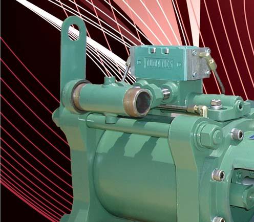
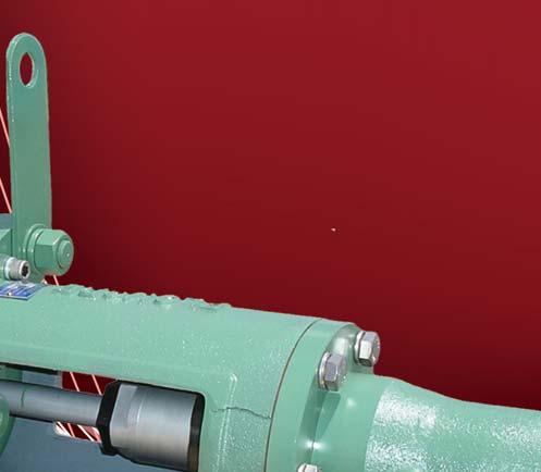
2 6200 Series Specifications The Flomore 6200 Series Pump line consists of a series of basic pump options all developed from a modular power unit. All units are pneumatically driven positive displacement, single or double acting, reciprocating pumps. The basic pump is designed for use with three fluid ends, a 1¼ and 2¾ diameter plunger, and a 4 piston. The fluid ends are interchangeable with the modular power unit and can be assembled as single ended units or double ended units in any combination of sizes. All fluid ends are designed to withstand maximum output force of the power unit. Due to the balanced valving of the power cylinder it is, in theory, possible to operate the pump against a back pressure equal to the inlet power gas pressure; however, a differential in these two pressures must be maintained for the pump to stroke. See Power to Fluid Ratio below. When the exhaust gas is piped off to other areas, the pilot valves may also be connected to the pump exhaust manifold system. Fluid ends are designed with removable check valves. These valves may be replaced without disconnecting the suction and discharge piping. Material Specifications Fluid End Fluid End Power End Models 6211, 6212, 6221, & 6222 Models 6241 & 6242 Part Material Part Material Part Material Main Power Cylinder Carbon Steel Pump Head Body Cast Steel (316SS Optional) Pump Head Body Cast Steel (316SS Optional) Power Cylinder End Cap Carbon Steel Valve Cover Carbon Steel Valve Cover Carbon Steel Power Piston Aluminum Valve Plug Stainless Steel Valve Plug Stainless Steel Power Piston Seals Buna-N Plunger Stainless Steel Roll Pin Stainless Steel Power Cylinder Seals Buna-N Valve Ball Stainless Steel Valve Ball Stainless Steel Power Piston Rod Stainless Steel Valve Seat Insert Stainless Steel Valve Seat Insert Stainless Steel Piston Rod Packing Gland Carbon Steel Valve Seat Gasket Teflon Valve Seat Gasket Teflon Piston Rod Packing Optional Valve Seat Seals Buna-N Piston Carbon Steel Packing Optional Piston Cup Buna-N Lantern Ring Stainless Steel Piston Rod Stainless Steel Packing Gland Delrin Cylinder Cast Ductile Iron Packing Nut Carbon Steel Cylinder Sleeve Stainless Steel 2
3 Installation and Operating Instructions 1. Remove pump from shipping container and inspect for possible shipping damage. If damaged, file a claim with the carrier. 2. Mount pump by bolting to a stable foundation. Four legs are supplied on the power unit for this purpose. 3. Connect fluid suction and discharge lines. Caution should be exercised to avoid piping stresses to the fluid head of the pump. A relief valve should be installed in the discharge line between the discharge check valve and the nearest shut off valve or auxiliary check valve. Caution: When pump is installed in a closed or hazardous area, power gas exhaust (including pilot devices) must be vented in a safe manner. All gas connections must be checked periodically for leaks. If power gas or air supply pressure exceeds 250 PSIG, a regulator and pressure relief valve of proper size must be installed. 4. Connect power supply lines as shown in Figure 1. Power supply pressure must not exceed 250 PSIG. 5. Fill lubricator reservoir with 1 quart SAE 10, SAE 20, or SAE 30 non-detergent oil dependent upon operating temperature. 6. For connections where it is necessary to pipe off exhaust gas such as back pressure service or pollution control, refer to Figure 3. Order Exhaust Manifold B-1126 and make all connections shown in Figure Open supply line slowly in order to check pump and system operation. 8. Adjust supply volume and pressure to regulate operating speed to meet desired conditions of discharge pressure and volume. 9. Adjust lubricator to minimum supply rate. 10. On 6200 pumps maintain plunger lubrication by adjusting grease jack periodically. *For safe operation, a safety valve sized to meet the maximum capacity of the supply source should be installed in the supply line at or near the pump. Operational Data Plunger Size 1¼ 2¾ 4 Pump Model Number Fluid Discharge Pressure Maximum 9000 PSI 1800 PSI 900 PSI Fluid Discharge Volumes up to Maximum Pressure See Chart Page 12 See Chart Page 12 See Chart Page 12 Operating Speed Maximum and Minimum See Chart Page 12 See Chart Page 12 See Chart Page 12 Power/Fluid Power Ratio (Inlet Gas Pressure - Exhaust Back Pressure) x Power to Fluid Ratio = 40:1 8:1 4:1 Maximum Fluid Discharge Pressure at Stall Pneumatic Pressure Required to Operate Pump See Chart Page 12 See Chart Page 12 See Chart Page 12 Maximum Temperature 200 F with Buna-N Trim 400 F with Viton Trim Minimum NPSHR 8 Feet of Water 3
4 Dimensional Data NOTE: Do not use for construction. Contact factory for certified dimensions when required. Figure 1: Model 6211 & 6221 The throttling valve filter and lubricator are included in the price of the pump and are furnished as loose pieces, along with the required nipples for field assembly. 3½ 12½ ¾ FNPT Air or Gas Inlet Throttling Valve Filter Lubricator 16¾ 14½ 13 6½ 2 1⅛ DIA 4 Holes Exhaust Manifold Piping B-1126 Exhaust Manifold (Optional) 17⅜ ± ¼ Figure 2: Model 6212 & ⅝ 1⅜ ½ FNPT Exhaust Ports 1⅜ C L ½ NPT Inlet 30⅝ ± ½ E NPT Discharge / 16 " 13⅛ Pilot Valve B-0928 ⅜ NPT 6¾ D C Pilot Valve B-0928 ⅜ NPT A ± ½ (Simplex) F NPT Suction B ± 1 (Duplex) Weights & Dimensions Model # A B C D E F Weight ¼ 8 ⅝ 4 11 /16 ¾ ¾ ¼ 8 ⅝ 4 11 /16 ¾ ¾ ¼ 9 5 /16 4 ¼ ¼ 9 5 /16 4 ¼ ½ 9 23 /32 3 ⅝ ⅝ 9 23 /32 3 ⅝
5 Dimensional Data NOTE: Do not use for construction. Contact factory for certified dimensions when required. Figure 3: Model 6241 E Discharge 1 2⅝ F Suction Figure 4: Exhaust Manifold B-1126 (optional) Cap 3 ¼ NPT Connect to pump exhaust ports ½ NPT Connect to pilot valve ¼ NPT located on each end of power cylinder ¼ NPT 1⅜ 1⅜ 1 15 / 32 1½ Exhaust outlet either end. Cap off end not in use. 5
6 6200 Series Power Unit (D-0365) Top View ¾ FNPT 1, ½ Exhaust Port ½ Exhaust Port Side View Stroke Pilot Valve Exhaust ⅜ FNPT Pilot Valve Exhaust ⅜ FNPT REF B-0928 REF B-0813 Page 8 See page13 for servicing instructions
7 Parts List Item Part # # Reqd. Description Material 1 A Lock Washer 304 Stainless Steel P015 4 Hex Head Cap Screw 316 Stainless Steel 3 A Nipple Steel 4 A Lubricator (1 quart capacity) Aluminum 5 A Nipple Steel 6 A Filter Aluminum 7 A Hex Bushing Steel 8 A ¼ Capacity Control Ball Valve 316 Stainless Steel 9 B Spool Valve Assembly Various 10 A Line 304 Stainless Steel 11 A Lifting Eye Steel 12 A Male Elbow Cadmium Plated Steel 13 C End Cap Steel 14 A Stud and Nut Assembly 304 Stainless Steel / Steel 15 A Male Elbow Cadmium Plated Steel *16 A Hex Head Cap Screw 304 Stainless Steel / Steel 17 A-0163SS 8 Hex Head Cap Screw 304 Stainless Steel 18 A Packing Plate Steel 19 A Gasket Buna-N and Cork 20 A Wire Screen Filter Brass 21 B Power Piston Assembly Aluminum 22 A Piston Seals Buna-N 23 C Manifold Ductile Iron 24 B Power Cylinder Steel 25 A O Ring Buna-N *26 A Power Rod Packing Buna-N 27 A O Ring Buna-N *28 A Gland Bushing Cast Iron *29 A Wiper Ring Buna-N *30 A Retainer Steel *31 A Belleville Washer Steel *32 A Back-up Ring Steel *33 A Ball Bearing Connection Carbon Steel *34 A Thrust Bearing Carbon Steel 35 A End Plug Cast Iron 36 B Pilot Valve See Page 8 *37 B Power Piston Rod 17-4 ph Stainless Steel 38 A-2813LW 8 Lock Washer 304 Stainless Steel *39 A Set Screw Steel *40 D Spacer Ductile Iron 41 A Pin (not shown) Brass 42 A Nameplate (not shown) Stainless Steel Notes: Recommended Spare Parts *Two parts or sets required on double head confi gurations Required only on single head confi guration 7
8 6200 Series Components Power Piston B-0813 Pilot Valve B-0928 Two Required (See Servicing Instructions - Page 13 & 14) Item Part # # Reqd. Description Material 1 C Piston Aluminum 2 B Bushing Steel 3 A Bushing Nut Steel 4 A Locking Ring Steel 1-Simplex 5 A Duplex Set Screw Steel Spool Valve B , (See Servicing Instructions - Page 13) Item Part # # Reqd. Description Material 1 A Sleeve Adapter Stainless Steel 2 A Gasket 304 Stainless Steel 3 A Spring Steel 4 A O Ring Buna-N 5 B Pilot Valve Body Steel 6 A O Ring Buna-N 7 A O Ring Buna-N 8 A Plunger Delrin *Recommended Spare Parts Item Part # # Reqd. Description Material 1 A End Cap Aluminum 2 A Detent Assembly Aluminum 3 A Bumper Urethane 4 A Screw Carbon Steel 5 A Lock Washer Carbon Steel 6 1 Body Assembly Aluminum 7 A Bumper Urethane 8 A O Ring Buna-N 9 A Screw Carbon Steel 10 A Lock Washer Carbon Steel 11 A Gasket Buna-N 12 A Sleeve Assembly Stainless Steel 13 A O Ring Seal Buna-N 8
9 Models 6211 & ¼ High Pressure Pump Head Assembly (D-0318 Cast Steel) (C Stainless Steel) ¼ Packing Chart Part # Material Max W.P. A-2850 Buna-N 3000 A-1014 Teflon 500 A-5290 Viton 3000 A-4133 Hard ¾ Suction and Discharge Parts List Item Part # # Reqd. Description Material 1 A Hex Head Cap Screw 316 Stainless Steel 2 A Washer 316 Stainless Steel 3 B Cover Steel 4 A Valve Plug Stainless Steel 5 A Back-up Ring Teflon 6 B Spacer 316 Stainless Steel P004 3 Gasket Teflon P023 2 Valve Seat Insert 316 Stainless Steel P /8 Valve Ball 440C Stainless Steel 10 A Pipe Plug Steel 11 D Pump Head Body Cast Steel 11.1 D-0500-SS 1 Pump Head Body Stainless Steel 12 B Plunger 17-4 ph Stainless Steel 13 See Packing Chart 1 Packing See Packing Chart 14 A Lantern Ring 304 Stainless Steel 15 A Cap Screw 316 Stainless Steel 16 A Lock Washer 316 Stainless Steel 17 A Packing Gland Delrin 18 A Packing Nut Steel 19 A Set Screw (S.H.) 303 Stainless Steel 20 A Ball Cup Connection Steel 21 A-2856 Buna-N or 3 O Ring A-4479 Viton 22 A Lube Stick A Stick Carton 23 A Grease Jack Steel *Recommended Spare Parts Not Included in Assembly 9
10 Models 6221 & ¾ Pump Head Assembly (D-0314 Cast Steel) (C Stainless Steel) ¾ Packing Chart Part # Material Max W.P. A-2861 Buna-N 1800 A-3296 TFE Buna 1800 A-4456 Viton Parts List Item Part # # Reqd. Description Material 1 A Hex Head Cap Screw 316 Stainless Steel 2 A Washer 316 Stainless Steel 3 A Cover Steel 4 A Valve Plug Stainless Steel 5 A-3853 Buna-N or 3 O Ring A-4479 Viton P ¼ Valve Ball 440C Stainless Steel 7 B Valve Seat Insert 316 Stainless Steel 8 A Pipe Plug Steel 9 D Pump Head Body Cast Steel 9.1 D-0501-SS 1 Pump Head Body Stainless Steel 10 See Packing Chart 1 Packing See Packing Chart 11 A Packing Gland Delrin 12 B Packing Nut Steel 13 B Plunger 17-4 ph Stainless Steel 14 A Thrust Plate Steel 15 A Lock Washer 316 Stainless Steel 16 A Cap Screw 316 Stainless Steel *Recommended Spare Parts Not Included in Assembly
11 Models 6241 & Pump Head Assembly (D-0348 Cast Steel) (C Stainless Steel) Parts List Item Part # # Reqd. Description Material 1 A Connector Cup Steel 2 A Wiper Ring Buna-N 3 B End Plug Steel 4 A Lock Washer 304 Stainless Steel 5 A Hex Head Screw 304 Stainless Steel 6 B Armaloy Piston Rod 17-4 ph Stainless Steel 7 A-3226 Buna-N or 1 O Ring A-4254 Viton 8 B Piston Carbon Steel 9 A Piston Cup Buna-N 10 A Backup Retainer 304 Stainless Steel 11 A Hex Nut 304 Stainless Steel 12 A Hex Head Screw 304 Stainless Steel 13 B Cover Steel 14 A Valve Plug 316 Stainless Steel 15 A-2104 Buna-N or 2 O Ring A-2171 Viton 16 A Roll Pin 316 Stainless Steel P Valve Ball 440C Stainless Steel 18 B Valve Seat Insert 316 Stainless Steel 19 D Pump Head Body Cast Steel 19.1 D-504-SS 1 Pump Head Body Stainless Steel P006 2 Gasket Teflon 21 A Set Screw 304 Stainless Steel 22 A Breather Assembly 23 C Cylinder Cast Ductile Iron 24 B Sleeve 304 Stainless Steel 25 A Backup Ring Buna-N 26 A-3218 Buna-N or 1 O Ring A-2155 Viton 27 A Plug Extension 303 Stainless Steel *Recommended Spare Parts 11
12 Discharge Pressure PSIG Discharge Pressure PSIG Minimum Recommended SPM Minimum Recommended SPM Performance Data Models 6211 & 6212 Models 6221 & 6222 Air Consumption Models 6211 & 6212 (Zero Back Pressure) Air Consumption Models 6221 & 6222 (Zero Back Pressure) Duplex 6211 Simplex Discharge Pressure PSIG Duplex 6221 Simplex ¼ Plunger ¾ Plunger Standard Cubic Feet of Air Required to Pump 1 Gallon of Liquid Standard Cubic Feet of Air Required to Pump 1 Gallon of Liquid 9000 Capacity Data Model 6211 Pump P=Inlet Air or Gas Supply Pressure Minus Exhaust (Back) Pressure 1800 Capacity Data Model 6221 Pump P=Inlet Air or Gas Supply Pressure Minus Exhaust (Back) Pressure Discharge Pressure PSIG Note: When air or gas P will be less than 100 PSIG. Contact factory for pump performance data. Discharge Pressure PSIG ΔP = 200 PSIG ΔP = 150 PSIG ΔP = 100 PSIG Note: When air or gas P will be less than 100 PSIG. Contact factory for pump performance data Gallons Per Minute Strokes Per Minute (6" Stroke Length Gallons Per Stroke) Air Consumption Models 6241 & 6242 (Zero Back Pressure) Models 6241 & Gallons Per Minute Strokes Per Minute (6" Stroke Length Gallons Per Stroke) Capacity Data Model 6241 Pump P = Inlet Air or Gas Supply Pressure Minus Exhaust (Back) Pressure Duplex 6241 Simplex Discharge Pressure PSIG PSIG (Max. Allowable), P = 200 PSIG P = 150 PSIG P = 100 PSIG Zero Back Pressure Note: When air or gas P will be less than 100 PSIG. Contact factory for pump performance data " Piston Standard Cubic Feet of Air Required to Pump 1 Gallon of Liquid Gallons Per Minute Strokes Per Minute (6" Stroke Length Gallons Per Stroke) 12
13 Servicing Instructions Power Unit D-0365, Page 6 & 7 CAUTION: Prior to performing any maintenance on the power or fluid end of this pump, all pneumatic and hydraulic pressure must be removed and isolated from the unit. Item #9 B-1510 (page 8) valve is a 2-position, 4-way spool valve with internal parts for bleeder pilot operation. To inspect, proceed as follows: 1. Remove 4 allen head cap screws #9 from pilot end caps. 2. Remove pilot end cap. (One end cap contains the detent body springs and balls.) 3. Remove bumper #7. 4. Remove spool and examine. 5. If required, the sleeve assembly #12 can be removed; however, this assembly contains the static o ring seals and may be difficult to reassemble. 6. To remove valve from pump, loosen 4 cap screws. NOTE: When reassembling, extreme care must be exercised to eliminate damage to the static o rings, to eliminate contamination on the sleeve and/or spool, and to protect end gaskets. Item #11 Control Lines: All connections must be tight and leak free. Item #23: Manifold must be securely fastened at both end cap connections and to the spool valve. When reassembling this unit, care must be exercised to protect o ring seals as leakage in this area will cause unit to short stroke or make unit entirely inoperative. Pilot valve assembly may be removed from the power end cap #13 as a unit. In reassembling this unit, care must be exercised to protect o ring seals as leakage in this area will cause unit to short stroke or make unit entirely inoperative. Disassembly of Pilot Valve B-0928, Page 8 1. Remove adapter #1 from sleeve #5. 2. Remove spring #3 and examine for set and stress failure. 3. Remove plunger #8 and examine angled seat face and O.D. surface of probe end. Probe end must be smooth enough to effect a pneumatic seal with o ring #7. 4. Examine all o rings and replace if necessary. Disconnect Fluid Head from Power Cylinder Page 6 1. Position pump in discharge position if possible. 2. Remove retainer #30 from cup (this is a right hand thread). Disconnect Fluid Head from Power Cylinder Page 6 Continued 3. Slowly apply power to withdraw power piston rod #37 from cup. If pump does not operate this connection may be pried apart. Disassembly of Power Cylinder (Power Unit D-0365, Page 6 & 7) 1. Loosen set screw #39 and remove connector bearing ball #33 from end of rod # Remove back-up ring #32, Belleville washers #31 and retaining nut # Remove 4 hex head screws #17 and packing plate # Disconnect both pilot control lines # Remove 4 manifold bolts #2. The valve and manifold assembly may be removed from the power cylinder. 6. Remove tie down bolts. 7. Remove hex nuts #1 from one end of each tie rod # Remove end caps #13 from cylinder # Remove piston #21 and power piston rod #37 from cylinder #24. Disassembly of Power Piston B-0813, Page 8 1. Bend down tab on both locking rings #4. 2. Remove bushing nut #3 from bushing #2. 3. Remove bushing #2 (with piston rod attached) from piston #1. 4. Remove set screw #5 from bushing #2. 5. Remove power piston rod from bushing #2. Assembly of Power Piston B-0813, Page 8 1. Install B-0810 power piston rod/rods into bushing #2 using Loctite #242 and tighten securely. 2. Install set screw/screws #5 using Loctite #242 and tighten firmly against power piston rod/rods. 3. Bend one (1) tab on each of two (2) locking rings #4, 90 to the plane of the ring. 4. Place one (1) locking ring #4 over bushing #2 (bent tab positioned away from bushing shoulder) and install assembly into piston #1 using Loctite #242. Postition locking ring #4 with bent tab engaged in hole in piston #1. Tighten bushing assembly into piston as tightly as possible. 13
14 Servicing Instructions Assembly of Power Piston B-0813, Page 8 Continued 3. Place other locking ring #4 over exposed thread on bushing #2 with bent tab positioned to engage hole in piston #1. Install bushing nut #3 and tighten as tight as possible. 4. Bend one exposed tab on each locking ring #4 up against a flat surface of the hex on both the bushing #2 and bushing nut #3. 5. Allow assembly to set one hour minimum for Loctite to fix. Assembly of Power Unit D-0365, Page 6 & 7 1. Lubricate I.D. of cylinder #24 and examine for surface defects. 2. Install piston seals ring #22 into last groove to inner cylinder #24 and insert piston #21 into cylinder. 3. Pass piston #21 though cylinder #24 until second groove is exposed. 4. Install other piston seal ring #22 and draw piston #21 back into cylinder # Examine ends of cylinder for possible damage. Place o ring #25 into groove in end cap #13 and install cylinder #24 into recess taking care not to pinch or otherwise damage o ring. 6. Place o ring #25 into groove in other end cap # Insert power piston rod #37 through center hole in end cap # Install tie rods #14. Torque hex nuts to approximately 130 ft/lbs. Make sure end plates #13 are brought up uniformly. 9. Position manifold gaskets #19 and manifold #23 over ports in end caps #13 making sure that gaskets do not block ports. 10. Secure manifold #23 with hex head cap screws #2 by tightening to approximately ft/lbs. 11. Install valve gasket and spool valve #9 and secure to manifold #23 with 4 socket head cap screws # Install pilot control lines # Lubricate center bore of end cap #13 and O.D. of power piston rod #37 and install rod packing # Install o ring #27 and wiper ring #29 into gland bushing # Place gland bushing #28 over power piston rod #37 and seat into place against packing # Position packing plate #18 against gland bushing #28 and tighten into place with 4 hex head cap screws #17. Do not overtighten. Assembly of Power Unit D-0365, Page 6 & 7 Continued 17. For double ended pumps, repeat steps 14 through 17 for opposite end. For single ended pumps, place o rings #27 onto end plug #35. Lubricate with a suitable grease and install end plug into end cap # Secure end plug #35 with packing plate #18 and 4 hex head cap screws #17 at approximately 10 ft/lbs. torque. 19. Assemble 2 pilot valves B-0928, Page 8, steps (a) through (e) (a) Install o ring #7 into I.D. of sleeve #5. (b) Install o rings #6 and #4 onto O.D. of sleeve #5. (c) Lubricate plunger #8 and insert into sleeve #5. (d) Place spring #3 over exposed end of plunger #8. (e) Install gasket #2 over end of adapter #1 and install adapter into sleeve # Lubricate O.D. seals of adapter #36 and install one pilot valve assembly into each end cap # Place retainer #30, 3 Belleville washers #31 and a back-up ring #32 over the end of the power piston rod # Install spacer #40 onto end cap #13 using 8 cap screws #16. Spacer should be oriented with ½ drain on bottom. (Two spacers required for double ended pumps.) Assembly of 6211 Head Assembly, Page 9 1. Examine head body #11 to make sure valve cage seating surface and packing areas are free of nicks and burrs. Check all thread areas for condition of threads. 2. Install seal #7 onto seal surface. 3. Install lower valve cage #8 and ball #9 into valve bore of pump head # Install o rings #21 and back-up rings #5 onto spacer cage #6 and lubricate seal area. 5. Install spacer cage #6 from step 4 into pump head # Install seal #7 onto seal surface inside spacer cage #6. 7. Install upper valve cage #8 and ball #9 into spacer cage. 8. Install o ring #21 and back-up ring #5 onto valve plug #4. 9. Place seal #7 on top surface of upper valve cage # Install valve plug #4 from step 8 into top of pump body. 14
15 Servicing Instructions Assembly of 6211 Head Assembly, Page 9 Continued 11. Place cover plate #3 over valve plug #4 and secure cover using 4 hex head cap screws #1 with lock washers #2. Torque to approximately ft/lbs. 12. Install pipe plug #10 using Loctite pipe sealant or equal. 13. Install packing #13 and lantern ring # Place packing gland #17 into packing gland nut #18 and thread assembly into pump body #11. Do not tighten more than hand tight. 15. Assemble ball connector cup #20 onto plunger #12 using Loctite #222 if availiable. Secure connection with set screw # Lubricate plunger #12 and insert through packing end of pump head # Install grease jack #23, containing 2 sticks of Chennola lubricant. NOTE: When using teflon packing, replace grease jack with pipe plug. Assembly of 6221 Head Assembly, Page Examine head body #9 to insure valve cage seating surfaces and packing areas are free of nicks and burrs. Check threaded areas for thread condition. 2. Install seal #5 onto lower seal surface. 3. Install lower valve cage #7 and valve ball #6 into pump head #9. 4. Install spacer cage #7. 5. Install seal #5 onto top surface of spacer cage #7. 6. Install top valve cage #7 and valve ball #6 into pump head # Place top seal #5 onto top surface of top valve cage #7. 8. Install valve plug #4. 9. Position cover plate #3 over valve plug #4 and secure using 2 hex head cap screws #1 with locknuts #2. Torque to approximately ft/lbs. 10. Install pipe plug #8 using Loctite pipe seal or equal. 11. Insert packing #10 into packing bore of pump body # Install packing gland #11 into packing gland nut #12 and thread assembly into pump body #9. Do not tighten more than hand tight. 13. Lubricate O.D. of plunger #13 and insert through packing end of pump head #19. Assembly of 6241 Head Assembly, Page Examine pump head #19 to insure valve cage sealing surfaces and cylinder sealing surface are free of defects. Check thread areas for thread condition. 2. Install seals #21 onto lower seal surfaces of each cavity in pump head # Install valve ball #17 into valve cage #18. Insert valve plug #14 into valve cage #18 and fasten with roll pin #16. Install o ring #15 onto valve plug #14 and lubricate each cavity in pump head # Insert plug and insert assembly into each cavity of pump head # Install plug #27 as shown. 6. Position cover plate #13 and secure using 3 hex head cap screws #12. Torque to approximately ft/lbs. 7. Assemble bell connector #1 onto end of piston rod #6 and secure with set screw # Install breather #22 and wiper ring #2 into end plug #3. 9. Insert piston rod #6 through end plug #3 as shown. 10. Position end plug #3 onto spacer and position cylinder #23 using 6 screws #5 and 6 washers #4. Flat end of cylinger must be used. Do not tighten this joint, leave at least ¼ gap. 11. Install sleeve #24 into cylinder # With piston rod #6 moved to full forward position, install o ring #7, piston #8, piston cup #9, back-up retainer #10 and nut # Install o ring #26 and back-up #25 onto end of sleeve # Place assembled pump head from step 10 over end of sleeve #24. Secure cylinder #23 to pump head using 6 screws #5 and 6 washers #4. This joint should be brought face to face. If a gap exists, loosen joint made in step After tightening cylinder to head connection, then tighten cylinder to spacer connection. A gap will exist at this joint - do not overtighten. Assembly of Fluid End to Power Units, Page 6 1. Insert ball joint thrust bearing #33 into connector cup. 2. Insert connector bearing ball #32 (on end of preassembled power piston rod #35) into connector cup and tighten retainer #29. Retainer should shoulder against end of connector cup without excessive pressure. 15
 599-9630 Fax: (817) 599-9167 Mike.Mayes@flomore.")
 984-3070 Fax: (903) 984-7901 Tammy.Hunt@flomore.")
16 Richart Distributors, Inc. Corporate Office 3415 South I-35 Service Road Oklahoma City, OK Fax: (405) Weatherford Branch 2041 FM 920 Weatherford, TX (817) Fax: (817) Dickinson Branch 533 East Villard Suite B Dickinson, ND (701) Fax: (701) RichartND@flomore.com Kilgore Branch 820 South Commerce Street Kilgore, TX (903) Fax: (903) Tammy.Hunt@flomore.com Louisiana Branch Cardon Sales Company, LLC 213 Cummings Road Broussard, LA (337) Fax: (337) bcardon@cardonsales.com Odessa Branch Patterson Equipment Sales, Inc 1610 S. Regal Avenue Odessa, TX (432) Fax: (432) chad@pattersonequipsalesinc.com IndustrialZone P.O. Box Houston, Texas United States (713) Fax: (713) support@industrialzone.com 16 June 28, 2011
6200 Series. Specifications. Fluid End Power End Models 6211, 6212, 6221, & 6222 Models 6241 & 6242 Part Material Part Material Part Material
 5.2018.12.i 6200 Series Specifications The Flomore 6200 Series Pump line consists of a series of basic pump options all developed from a modular power unit. All units are pneumatically driven positive
Parts List. Item # Part # # Reqd. Description
 5.2017.6.f 1 3800 Series Injector 1 2 3 4 5 6 7 21 8 9 20 10 11 12 19 18 17 16 15 14 13 Parts List Item # Part # # Reqd. Description 1 A-0664 1 5 Gallon 430 Reservoir 2 A-0575 1 Thumb Screw 3 A-0172 1
5020 Series Injector
 5.2018.9.k 1 5020 Series Injector 1 2 3 4 5 6 10 11 7 12 13 8 2 14 Parts List 15 16 17 Item # Part # # Reqd. Description Material Alternate Part # 1 A-1854 1 0-12 PSI Pressure Gauge A-1295SS 2 A-0022 1
Item # Part # Description Item # Part # Description
 5.2018.5.h 1 1300 Series Injector Item # Part # Description 1 F-0871 Stainless Steel Tank Gauge Assembly 2 A-0535 Base Assembly 3 A-3118 Connector Compression Nut Assembly 4 A-3117 Suction Line 5 A-1497
More Drum Gauge Features
 5.20..f Features Unique Features Offered By Flomore» Red-lined sight glass.» Acrylic covers for protection with screen printed markings.» Multiple material options to choose from.» Buna or Viton sealing
Solar Power Injector. Parts List. For A Complete Pump As Shown 3/ SS 1/ SS 3/ SS 1/ SS 3/ SS
 5.2016.25.j 1 2000 Solar Power Injector 10 9 For A Complete Pump As Shown 3/16 20-04SS 1/4 20-01SS 3/8 20-03SS 1/2 20-05SS 3/4 20-06SS 11 7 8 1 2 6 3 5 4 2 Parts List Item # Part# Description 1 2000 Series
series5000 GAS/PNEUMATIC DRIVEN INJECTION PUMP TEXSTEAM Pumps DESCRIPTION APPLICATIONS
 TEXSTEAM Pumps series5000 GAS/PNEUMATIC DRIVEN INJECTION PUMP DESCRIPTION Texsteam Series 5000 chemical injectors are positive displacement units powered by integral gas/air motor. These pumps fill the
AF0465-XX SERVICE KITS GENERAL DESCRIPTION MODEL DESCRIPTION CHART OPERATING AND SAFETY PRECAUTIONS THIS MANUAL COVERS THE FOLLOWING MODELS
 OPERATOR S MANUAL INCLUDING: SERVICE KITS, TROUBLESHOOTING, PARTS LIST, DISASSEMBLY & REASSEMBLY. 4-1/4 AIR MOTORS AF044X-XX (4 STROKE) and AF046X-XX (6 STROKE) Also covers 637489 service kits AF044X-XX
series 5100 GAS/PNEUMATIC DRIVEN INJECTION PUMP DESCRIPTION APPLICATIONS
 TEXSTEAM Pumps series 5100 GAS/PNEUMATIC DRIVEN INJECTION PUMP Series 5100 LP Wt. 45 pounds Microswitch Option Available DESCRIPTION The 5100 Series performs accurately because (1) the head is designed
CUSTOM COMBINATION AIR VALVE
 INSTALLATION / OPERATION / MAINTENANCE CUSTOM COMBINATION AIR VALVE INTRODUCTION This manual will provide you with the information to properly install and maintain this valve to ensure a long service life.
series4300 ELECTRIC DRIVEN INJECTION PUMP DESCRIPTION FEATURES
 TEXSTEAM Pumps series4300 ELECTRIC DRIVEN INJECTION PUMP DESCRIPTION The series 4300 chemical injectors are electric motor driven, positive displacement pumps utilizing an integral worm gear drive available
DESCRIPTION FEATURES. facilities, pipelines, process plants and other applications where a rugged, easy to maintain proportioning pump is required.
 DESCRIPTION The series 4300 chemical injectors are electric motor driven, positive displacement pumps utilizing an integral worm gear drive available in three different standard ratios and 6 plunger sizes
series2500 TEXSTEAM Pumps ELECTRIC DRIVEN INJECTION PUMP PRODUCT FEATURES MODEL DESIGNATION
 TEXSTEAM Pumps series2500 ELECTRIC DRIVEN INJECTION PUMP PRODUCT FEATURES Maximum discharge pressure: 6,000 PSI (1 bar) w/ 3/16 plunger Maximum volume gallons per day (52 liters per day) w/ 1/2 plunger
HIGH PRESSURE CONTROL VALVE PISTON BALANCED
 PISTON BALANCED All Rights Reserved. All contents of this publication including illustrations are believed to be reliable. And while efforts have been made to ensure their accuracy, they are not to be
KP-C Series. Close Coupled End Suction Centrifugal Pumps. Installation, Operation and Maintenance
 KP-C Series Close Coupled End Suction Centrifugal Pumps Installation, Operation and Maintenance PUMP MODEL NOMENCLATURE KP - 8 x 6 x 16 - E C - AI - BCM Pump Series Suction Pipe Size (in) Discharge Pipe
Bulletin C Dean Pump Division. Heavy Duty, High Temperature Process Pumps. R4140 Telescoping Guard. R4140 C-Face Motor Support
 Bulletin C 1.4.43 Dean Pump Division Heavy Duty, High Temperature Process Pumps R4140 Telescoping Guard R4140 C-Face Motor Support Dean Pump Series R Centrifugal Process Pumps Capacities to 5000 GPM (1135
Product Manual. CVS Series 51 Chemical Injection Pump. Applications. Description
 Product Manual CVS Series 51 Chemical Injection Pump Applications 1. The introduction of De-Emulsifiers, corrosion Inhibitors De-scaling Agents, Solvents and Oxygen Scavengers. 2. Water Treatment 3. Methanol
Appendix D Outline Dimensions
 Appendix D Outline Dimensions Model D81 Bare with Flywheel Suction valve unloaders (optional) 5-1/2" (13.) 5-1/2" (13.) 1/4" NPT drain Inlet 2" Weld flange Inlet pressure guage Outlet pressure gauge Outlet
Instruction Manual. CVS Series 50 Chemical Injection Pump. Introduction. Applications
 Instruction Manual CVS Series 50 Chemical Injection Pump Introduction The CVS Series 50 Chemical Injection Pump is a positive displacement pump that uses a molded diaphragm to drive a piston through packing
OPERATION MANUAL 1 POLYPROPYLENE PUMP DURA-FLO TM AIR DISTRIBUTION SYSTEM
 OPERATION MANUAL 1 POLYPROPYLENE PUMP DURA-FLO TM AIR DISTRIBUTION SYSTEM CAUTIONS - READ FIRST CAUTION: Do not apply compressed air to the exhaust port pump will not function. CAUTION: Do not exceed 82
GH-BETTIS OPERATING & MAINTENANCE INSTRUCTIONS DISASSEMBLY & ASSEMBLY FOR THE T80X-M4-S DOUBLE ACTING SERIES HYDRAULIC ACTUATORS
 GH-BETTIS OPERATING & MAINTENANCE INSTRUCTIONS DISASSEMBLY & ASSEMBLY FOR THE T80X-M4-S DOUBLE ACTING SERIES HYDRAULIC ACTUATORS -S INDICATES CYLINDERS ARE IN TANDEM PART NUMBER: 100121 REVISION "A" ECN
OPERATION MANUAL INTERNAL GEAR PUMP. Models: NG-H, NG-HL, NG-K, NG-KK, NG-L, NG-LQ, NG-LL, NG-LS, NG-Q, NG-QS. Tel: Fax:
 OPERATION MANUAL INTERNAL GEAR PUMP Models: NG-H, NG-HL, NG-K, NG-KK, NG-L, NG-LQ, NG-LL, NG-LS, NG-Q, NG-QS. 1 Contents Pump Designation System Maintenance Thrust bearing adjustment Pressure Relief Valve
GH-BETTIS SERVICE INSTRUCTIONS DISASSEMBLY & REASSEMBLY FOR MODELS HD521-M4, HD721-M4 AND HD731-M4 DOUBLE ACTING SERIES PNEUMATIC ACTUATORS
 GH-BETTIS SERVICE INSTRUCTIONS DISASSEMBLY & REASSEMBLY FOR MODELS HD521-M4, HD721-M4 AND HD731-M4 DOUBLE ACTING SERIES PNEUMATIC ACTUATORS WITH HYDRAULIC CONTROL PACKAGE PART NUMBER: SE-023 REVISION:
OPERATOR S MANUAL C INCLUDING: OPERATION, INSTALLATION & MAINTENANCE RELEASED:
 OPERATOR S MANUAL 650719-C INCLUDING: OPERATION, INSTALLATION & MAINTENANCE RELEASED: 8-11-03 REVISED: 12-3-10 (REV. 08) 2" DIAPHRAGM PUMP U.L. LISTED, 1:1 RATIO, METALLIC READ THIS MANUAL CAREFULLY BEFORE
Appendix D Outline Dimensions
 Appendix D Outline Dimensions Models 91 691 and F91 F691 Bare with Flywheel L L1 M M1 M M1 L L1 Outline Dimensions Inches (Centimeters) Model A B C D E F G H J K 91, F91 1-13/16 2-3/8 3-11/16 13/32 5/8
SERVICE INSTRUCTIONS. Material Pump
 TM TM SERVICE INSTRUCTIONS Material Pump 9618 DESCRIPTION Model 9618 is designed for pumping petroleum products from the original container to a desired location. Due to its non-corrosive (aluminum and
INDUSTRIAL PUMPS MODEL: D-35-SD PARTS MANUAL SLURRY DUTY PUMP WANNER ENGINEERING, INC. IMPORTANT
 PARTS MANUAL INDUSTRIAL PUMPS IMPORTANT Record your pump model number and serial number here for easy reference: Model No. MODEL: D-35-SD SLURRY DUTY PUMP Serial No. Date of Purchase When ordering parts
KAM IAS ISOKINETIC AUTOMATIC SAMPLER. User Manual IASMANUAL-0513 KAM CONTROLS, INC Ann Arbor Drive Houston, Texas USA
 An ISO 900 certified company TEL + 73 784-0000 FAX + 73 784-000 Email Sales@Kam.com KAM IAS ISOKINETIC AUTOMATIC SAMPLER PER API 8.2, ASTM D477 AND ISO 37 User Manual IASMANUAL-053 3939 Ann Arbor Drive
MODEL 5540 CONTENTS. Installation, Operation and Maintenance Instructions 1.0 GENERAL
 Installation, Operation and Maintenance Instructions MODEL 5540 Sep 20 CONTENTS.0 GENERAL. Model Number---------------------------------------------------------------------------------------------------------------
PARTS LIST FOR AIR COMPRESSORS AC-SH20-2 AC-SV20-2 ENGINE OIL GRADE: HONDA: SAE 10W-30. Below 40 F=SAE 10W-30 ENGINE OIL CAPACITY:
 PARTS LIST FOR AIR COMPRESSORS AC-SH20-2 AC-SV20-2 ENGINE OIL GRADE: HONDA: SAE 10W-30 VANGUARD: Above 40 F=SAE30 Below 40 F=SAE 10W-30 ENGINE OIL CAPACITY: HONDA: 37 oz. VANGUARD: 40 oz. MAXIMUM PRESSURE
Property of American Airlines
 Date: September, 00 MALABAR INTERNATIONAL AIRCRAFT MAINTENANCE & SUPPORT EQUIPMENT READ AND SAVE THIS INSTRUCTION MANUAL OWNER'S MANUAL FOR MALABAR MODEL A SINGLE STAGE VARIABLE HEIGHT HYDRO - MECHANICAL
Type 644 and 645 Differential Pressure Pump Governors
 Instruction Manual 644 and 645 Pump Governors Type 644 and 645 Differential Pressure Pump Governors Introduction Scope of Manual This instruction manual provides information on installation, adjustment,
Specifications Information and Repair Parts Manual , , , &
 Please read and save this Repair Parts Manual. Read this manual and the General Operating Instructions carefully before attempting to assemble, install, operate or maintain the product described. Protect
Chemical Injection Pump
 TEXSTEAM MX3 SERIES Chemical Injection Pump TEXSTEAM INC. Chemical Injection Pump Product Features Up to 62 gallons (235 liters) per day Lightweight Discharge pressures to 10,000 PSI (690 bars) Adjustable
ACHL Series Pump. Operation and Maintenance Manual Air Driven, Hand Operated High Pressure Liquid Pump
 ACHL Series Pump Operation and Maintenance Manual Air Driven, Hand Operated High Pressure Liquid Pump Catalog: 02-9245ME February 2013 Model # Serial # Drawing # Order # Mfg. Date Table of Contents page
ASSEMBLY MANUAL SMC 2491 LOADER VALVE AND PLUMBING KIT INSTRUCTIONS KUBOTA TRACTORS
 ASSEMBLY MANUAL Keep With Loader Operator's Manual SMC 2491 LOADER VALVE AND PLUMBING KIT INSTRUCTIONS KUBOTA TRACTORS MODEL 2WD 4WD LESS CAB WITH CAB L5450 X X Valve and plumbing kit can be installed
High Lift Transmission Jack
 SPX Corporation 655 Eisenhower Drive Owatonna, MN 55060-0995 USA Phone: (507) 455-7000 Tech. Serv.: (800) 533-6127 Fax: (800) 955-8329 Order Entry: (507) 455-1480 Fax: (800) 283-8665 International Sales:
Fisher 1061 Pneumatic Piston Rotary Actuator with Style H & J Mounting Adaptations
 Instruction Manual 1061 H & J Actuator Fisher 1061 Pneumatic Piston Rotary Actuator with Style H & J Mounting Adaptations Contents Introduction... 1 Scope of Manual... 1 Description... 2 Specifications...
OPERATOR S MANUAL SERVICE KITS PUMP DATA MODEL DESCRIPTION CHART INCLUDING: OPERATION, INSTALLATION & MAINTENANCE RELEASED:
 OPERATOR S MANUAL 670097 INCLUDING: OPERATION, INSTALLATION & MAINTENANCE RELEASED: 2-2-10 REVISED: 10-16-15 (REV. H) 3" DIAPHRAGM PUMP 1:1 RATIO (METALLIC) READ THIS MANUAL CAREFULLY BEFORE INSTALLING,
OPERATION MANUAL NT50 NOMAD TRANS-FLO AIR-OPERATED DOUBLE DIAPHRAGM PUMPS. A JDA Global Company. 7/11 rev. 1
 OPERATION MANUAL NT50 NOMAD TRANS-FLO AIR-OPERATED DOUBLE DIAPHRAGM PUMPS A JDA Global Company 7/11 rev. 1 CAUTION SAFETY POINTS TEMPERATURE LIMITS: Neoprene -17.8 C to 93.3 C 0 F to 200 F Buna-N -12.2
12 SERIES. Product Information. Performance & Specs. All 300 Series S.S. construction. Compact, easy to mount 11" x 9" x 3", weighs only 7lb. 2 oz.
 AEPB0 March 2009 2 SERIES 2 Features All 300 Series S.S. construction Compact, easy to mount " x 9" x 3", weighs only 7lb. 2 oz. Mounts in vertical position for easy operation Up to a maximum 5500 PSI
HYDRAULICS. TX420 & & lower. Hydraulic Tandem Pump Removal. 4. Remove the LH side panel (Fig. 0388).
.") TX420 & 425 240000299 & lower 4. Remove the LH side panel (Fig. 0388). Hydraulic Tandem Pump Removal Note: Cleanliness is a key factor in a successful repair of any hydraulic system. Thoroughly clean all
TX420 & 425 240000299 & lower 4. Remove the LH side panel (Fig. 0388). Hydraulic Tandem Pump Removal Note: Cleanliness is a key factor in a successful repair of any hydraulic system. Thoroughly clean all
INSTRUCTION MANUAL AND PARTS LIST FOR A3D SERIES PUMPS
 TM INSTRUCTION MANUAL AND PARTS LIST FOR A3D SERIES PUMPS WARNING This Instruction Manual and General Instructions Manual SRM00046, should be read thoroughly prior to pump installation, operation or maintenance.
Fast-Flo Pump INSTRUCTIONS-PARTS LIST. Table of Contents 1:1 RATIO
 INSTRUCTIONS-PARTS LIST INSTRUCTIONS This manual contains important warnings and information. READ AND KEEP FOR REFERENCE. First choice when quality counts. 07 7 Rev. Z Supersedes W Includes Rev. Y changes
Instructions Parts List
 Instructions Parts List : RATIO Fast Flo Pump Air operated piston transfer pump for low viscosity fluids. For professional use only. Only models that are EX certified are approved for use in European explosive
66M170-XXX-C RELEASED: REVISED: (REV. 05) 1-1/2" DIAPHRAGM PUMP
 1-1/2 DIAPHRAGM PUMP") OPERATOR S MANUAL INCLUDING: OPERATION, INSTALLATION & MAINTENANCE 1-1/2" DIAPHRAGM PUMP 1:1 RATIO, METALLIC 66M150-XXX-C 66M170-XXX-C RELEASED: 11-3-08 REVISED: 8-25-10 (REV. 05) READ THIS MANUAL CAREFULLY
OPERATOR S MANUAL INCLUDING: OPERATION, INSTALLATION & MAINTENANCE 1-1/2" DIAPHRAGM PUMP 1:1 RATIO, METALLIC 66M150-XXX-C 66M170-XXX-C RELEASED: 11-3-08 REVISED: 8-25-10 (REV. 05) READ THIS MANUAL CAREFULLY
Type N550 Snappy Joe Emergency Shutoff Valves
 Instruction Manual MCK-1149 Type N550 March 2010 Type N550 Snappy Joe Emergency Shutoff Valves Failure to follow these instructions or to properly install and maintain this equipment could result in an
UV PROCESS SUPPLY, INC. CON-TROL-CURE ½ DIAPHRAGM PUMP INSTRUCTION MANUAL PART # J
 1 IMPORTANT: READ THIS MANUAL CAREFULLY BEFORE INSTALLING, OPERATING OR SERVICING. PUMP DATA TYPE: MAT'L: WEIGHT: Air Operated Double Diaphragm Polypropylene or PVDF or Acetal PVDF (Polyvinylidene Fluoride)
1-1/2 DIAPHRAGM PUMP 1:1 RATIO (METALLIC)
") OPERATOR S MANUAL INCLUDING: OPERATION, INSTALLATION & MAINTENANCE 1-1/2 DIAPHRAGM PUMP 1:1 RATIO (METALLIC) 66615X-X-C RELEASED: 5-31-88 REVISED: 1-2-07 (REV. X) READ THIS MANUAL CAREFULLY BEFORE INSTALLING,
OPERATOR S MANUAL INCLUDING: OPERATION, INSTALLATION & MAINTENANCE 1-1/2 DIAPHRAGM PUMP 1:1 RATIO (METALLIC) 66615X-X-C RELEASED: 5-31-88 REVISED: 1-2-07 (REV. X) READ THIS MANUAL CAREFULLY BEFORE INSTALLING,
1-1/2" DIAPHRAGM PUMP 1:1 Ratio (metallic) with Cone Checks
 with Cone Checks") OPERATOR S MANUAL 670053-X-X INCLUDING: OPERATION, INSTALLATION & MAINTENANCE RELEASED: 3-24-06 REVISED: 5-11-15 (REV. F) 1-1/2" DIAPHRAGM PUMP 1:1 Ratio (metallic) with Cone Checks READ THIS MANUAL CAREFULLY
OPERATOR S MANUAL 670053-X-X INCLUDING: OPERATION, INSTALLATION & MAINTENANCE RELEASED: 3-24-06 REVISED: 5-11-15 (REV. F) 1-1/2" DIAPHRAGM PUMP 1:1 Ratio (metallic) with Cone Checks READ THIS MANUAL CAREFULLY
Pneumatic Chemical Metering Pump
 Timberline s was designed with the well pumper and the chemical man in mind. Each pump has a simple but rugged design that can be repaired in the field within minutes on the tailgate of a pickup truck.
OPERATION MANUAL. ALUMINUM Models DUCTILE Models 316 S.S. Models AIR-OPERATED DOUBLE DIAPHRAGM PUMPS
 OPERATION MANUAL 3 METALLIC PUMP (CLAMPED) PWR-FLO TM AIR DISTRIBUTION SYSTEM NPF80 AIR-OPERATED DOUBLE DIAPHRAGM PUMPS ALUMINUM Models DUCTILE Models 316 S.S. Models A JDA Global Company CAUTIONS - READ
Amarillo PUMP DRIVES (250 HP THROUGH 350 HP) INSTRUCTIONS FOR REPAIRING MODELS 250, 300, and 350
 INSTRUCTIONS FOR REPAIRING MODELS 250, 300, and 350") Amarillo PUMP DRIVES (250 HP THROUGH 350 HP) INSTRUCTIONS FOR REPAIRING MODELS 250, 300, and 350 Amarillo Right Angle Pump Drives, if properly installed and maintained, should provide years of service
Amarillo PUMP DRIVES (250 HP THROUGH 350 HP) INSTRUCTIONS FOR REPAIRING MODELS 250, 300, and 350 Amarillo Right Angle Pump Drives, if properly installed and maintained, should provide years of service
E8 Mini-Matic 3/8" Bolted Plastic Pumps Operating Instructions
 E8 Mini-Matic 3/8" Bolted Plastic Pumps Operating Instructions Polypropylene SAFETY WARNINGS Read these instructions completely before installation and start-up. It is the responsibility of the purchaser
Fisher 657 Diaphragm Actuator Sizes and 87
 Instruction Manual 657 Actuator (30-70 and 87) Fisher 657 Diaphragm Actuator Sizes 30 70 and 87 Contents Introduction... 1 Scope of Manual... 1 Description... 2 Specifications... 2 Installation... 3 Mounting
INSTRUCTION MANUAL INTERNAL GEAR PUMP TITAN G-4124A SERIES=> FLANGED TITAN G-124A SERIES => FLANGED MODELS:
 INSTRUCTION MANUAL INTERNAL GEAR PUMP TITAN G-4124A SERIES=> FLANGED TITAN G-124A SERIES => FLANGED MODELS: G-H, G-HL, G-K, G-KK, G-L, G-LQ, G-LL, GLS, G-Q, G-QS 1 Contents Maintenance Thrust bearing adjustment
Tech. Services: (800) Fax: (800) Order Entry: (800) Fax: (800)
 Fax: (800) Order Entry: (800) Fax: (800)") SPX Corporation 5885 11th Street Rockford, IL 61109-3699 USA Tech. Services: (800) 477-8326 Fax: (800) 765-8326 Order Entry: (800) 541-1418 Fax: (800) 288-7031 Parts List for: Form No. 108184 RSST-20 Internet
SPX Corporation 5885 11th Street Rockford, IL 61109-3699 USA Tech. Services: (800) 477-8326 Fax: (800) 765-8326 Order Entry: (800) 541-1418 Fax: (800) 288-7031 Parts List for: Form No. 108184 RSST-20 Internet
D 25 POLYPROPYLENE (BOLTED)
") www.tablapump.com A COMPLETE RANGE OF AIR DIAPHRAGM PUMPS CONGRATULATIONS ON PURCHASING YOUR NEW TABLA PUMP! IMPORTANT: Please read all the installation and safety information carefully before you start
www.tablapump.com A COMPLETE RANGE OF AIR DIAPHRAGM PUMPS CONGRATULATIONS ON PURCHASING YOUR NEW TABLA PUMP! IMPORTANT: Please read all the installation and safety information carefully before you start
STAINLESS STEEL SERIES LSSW HIGH PRESSURE HYDRAULIC CYLINDERS INSTALLATION & OPERATING INSTRUCTIONS
 CATALOG: LSSW-00 STAINLESS STEEL SERIES LSSW HIGH PRESSURE HYDRAULIC CYLINDERS INSTALLATION & OPERATING INSTRUCTIONS REMEMBER.... WHEN PERFORMANCE COUNTS SPECIFY LEHIGH LEHIGH FLUID POWER, INC. 1413 ROUTE
GROOVED END FLO-TREX COMBINATION VALVE
 FILE NO.: 35.80L DATE: Feb. 20, 2010 SUPERSEDES: 6-1/OM/1 DATE: Jan. 2005 INSTALLATION AND OPERATING INSTRUCTIONS GROOVED END FLO-TREX COMBINATION VALVE Angle Pattern Model FTV-A Pattern Model FTV-S TABLE
VALVE AND PLUMBING KIT 2409 LOADER CUB CADET & KIOTI TRACTORS
 ASSEMBLY MANUAL Keep With Operator s Manual VALVE AND PLUMBING KIT 2409 LOADER CUB CADET & KIOTI TRACTORS TRACTOR MODELS CUB CADET 8404, 8454 KIOTI DK45, DK50 ROPS X X TRACTOR AND VALVE KIT GENERAL INFORMATION
OPERATION AND MAINTENANCE MANUAL 2-66 SERIES 2500 RESILIENT WEDGE GATE VALVE
 OPERATION AND MAINTENANCE MANUAL 2-66 SERIES 2500 RESILIENT WEDGE GATE VALVE INDEX SERIES 2500 DUCTILE IRON RESILIENT WEDGE GATE VALVE OPERATION and MAINTENANCE MANUAL. OPERATION AND MAINTENANCE Operation,
Corken Compressor Repair
 Corken Compressor Repair Click photo to make move Gauge Openings Inspection plate with model and serial #s Oil filter and oil pump assembly Crankcase breather vent Crankcase breather location. If excess
OPERATION MANUAL. ALUMINUM Models DUCTILE Models 316 S.S. Models AIR-OPERATED DOUBLE DIAPHRAGM PUMPS
 OPERATION MANUAL 2 METALLIC PUMP (CLAMPED) PWR-FLO TM AIR DISTRIBUTION SYSTEM NPF50 AIR-OPERATED DOUBLE DIAPHRAGM PUMPS ALUMINUM Models DUCTILE Models 316 S.S. Models A JDA Global Company CAUTIONS - READ
OPERATION, MAINTENANCE AND OVERHAUL INSTRUCTIONS FOR PB18 SERIES PORTABLE PUMPS
 WATEROUS COMPANY Form No. F 2058 South St. Paul, Minnesota 55075 January, 1992 OPERATION, MAINTENANCE AND OVERHAUL INSTRUCTIONS FOR PB18 SERIES PORTABLE PUMPS Printed in U.S.A. Waterous Company F 2058
D 40 ALUMINIUM (CLAMPED)
") www.tablapump.com A COMPLETE RANGE OF AIR DIAPHRAGM PUMPS CONGRATULATIONS ON PURCHASING YOUR NEW TABLA PUMP! IMPORTANT: Please read all the installation and safety information carefully before you start
www.tablapump.com A COMPLETE RANGE OF AIR DIAPHRAGM PUMPS CONGRATULATIONS ON PURCHASING YOUR NEW TABLA PUMP! IMPORTANT: Please read all the installation and safety information carefully before you start
3.2 DRIVE TORQUE HUB. Roll, Leak and Brake Testing SECTION 3 - CHASSIS & TURNTABLE. 3-2 JLG Lift
 3.2 DRIVE TORQUE HUB Roll, Leak and Brake Testing 10 LUG PATTERN Torque-Hub units should always be roll and leak tested before disassembly and after assembly to make sure that the unit's gears, bearings
TECHNICAL DATA 1-1/2 (dn40)
") July 1, 2011 Deluge Valves 209a DESCRIPTION The Viking Model E-3 1-1/2 Deluge Valve is a quick-opening, differential type flood valve with a rolling diaphragm clapper. The deluge valve is used to control
July 1, 2011 Deluge Valves 209a DESCRIPTION The Viking Model E-3 1-1/2 Deluge Valve is a quick-opening, differential type flood valve with a rolling diaphragm clapper. The deluge valve is used to control
VALVE AND PLUMBING KIT INSTRUCTIONS SMC 84Q & 2408 LOADERS NEW HOLLAND TRACTORS MODEL 2WD 4WD LESS CAB WITH CAB 1720 X X X 1920 X X X
 ASSEMBLY MANUAL Keep With Operator s Manual VALVE AND PLUMBING KIT INSTRUCTIONS SMC 84Q & 2408 LOADERS NEW HOLLAND TRACTORS MODEL 2WD 4WD LESS CAB WITH CAB 1720 X X X 1920 X X X TRACTOR AND VALVE KIT GENERAL
OPERATION MANUAL 2 POLYPROPYLENE PUMP DURA-FLO TM AIR DISTRIBUTION SYSTEM
 OPERATION MANUAL 2 POLYPROPYLENE PUMP DURA-FLO TM AIR DISTRIBUTION SYSTEM CAUTIONS - READ FIRST CAUTION: Do not apply compressed air to the exhaust port pump will not function. CAUTION: Do not exceed 82
Versa-Matic. Operating Manual. 3/8" Bolted Plastic Pumps. Polypropylene Kynar
 Versa-Matic Operating Manual 3/8" Bolted Plastic Pumps Polypropylene Kynar E8 SAFETY WARNINGS Read these instructions completely before installation and start-up. It is the responsibility of the purchaser
Model SMA3-A SLUDGEMASTER
 SERVICE AND OPERATING MANUAL Model SMA3-A SLUDGEMASTER PLEASE NOTE! The photos shown in this manual are for general instruction only. YOUR SPECIFIC MODEL MAY NOT BE SHOWN. Always refer to the parts list
VALVE AND PLUMBING KIT NEW HOLLAND 7310 LOADER NEW HOLLAND TRACTORS
 ASSEMBLY MANUAL Keep With Operator s Manual VALVE AND PLUMBING KIT NEW HOLLAND 73 LOADER NEW HOLLAND TRACTORS MODEL 2WD FWA LESS CAB WITH CAB TT55 X X X TT75 X X X Valve and plumbing kit can be installed
Quincy QR-25. Series Model 325. Quincy. Compressor. Parts Manual Record of Change 105
 Quincy QR- Series Model 3 s Manual Record of Change 10 This manual contains important safety information and should be made available to all personnel who operate and/or maintain this product. Carefully
VALVE AND PLUMBING KIT 2408TL LOADER AGCO & MASSEY FERGUSON TRACTORS
 ASSEMBLY MANUAL Keep With Operator s Manual VALVE AND PLUMBING KIT 2408TL LOADER AGCO & MASSEY FERGUSON TRACTORS AGCO MASSEY FERGUSON CAB ROPS ST34A 1533 X ST41A 1540 N/A X TRACTOR AND VALVE KIT GENERAL
1 HIGH PRESSURE DIAPHRAGM PUMP 3:1 RATIO (METALLIC)
") OPERATOR S MANUAL INCLUDING: OPERATION, INSTALLATION & SERVICE 1 HIGH PRESSURE DIAPHRAGM PUMP 3:1 RATIO (METALLIC) RELEASED: 7-7-00 REVISED: 3-2-06 (REV. H) READ THIS MANUAL CAREFULLY BEFORE INSTALLING,
OPERATOR S MANUAL INCLUDING: OPERATION, INSTALLATION & SERVICE 1 HIGH PRESSURE DIAPHRAGM PUMP 3:1 RATIO (METALLIC) RELEASED: 7-7-00 REVISED: 3-2-06 (REV. H) READ THIS MANUAL CAREFULLY BEFORE INSTALLING,
CONTENTS. VIKING PUMP, INC. A Unit of IDEX Corporation Cedar Falls, IA USA SECTION TSM 710.1
 TECHNICAL SERVICE MANUAL industrial heavy duty motor speed pumps SERIES 4076 AND 4176 SIZES hle, ate and ale SECTION TSM 710.1 PAGE 1 of 8 ISSUE B CONTENTS Introduction....................... 1 Safety
PRESSURE REGULATOR BACK PRESSURE TO ATMOSPHERE WITH OUTSIDE SUPPLY
 PRESSURE REGULATOR BACK PRESSURE TO ATMOSPHERE WITH OUTSIDE SUPPLY All Rights Reserved. All contents of this publication including illustrations are believed to be reliable. And while efforts have been
Form No Parts List for: MODEL B HYDRAULIC PUMP GENERAL SECTION PG PG553-2UK FT600 PG554. PG120A Series Y70G Series. Sheet No.
 MODEL B HYDRAULIC PUMP GENERAL SECTION Parts List for: Form No. 100520 60208 PG553 65820 PG553-2UK FT600 PG554 FT700-001 PG554-LEAD FT700-002 PG554-2UK PG55A Series Y26G Series PG90A Series Y60G Series
Technical Data P3 PISTON POWER PUMP NON-ELECTRIC CONDENSATE PUMP SD 9952B
 Technical Data SD 9952B SPENCE ENGINEERING COMPANY, INC. 150 COLDENHAM ROAD, WALDEN, NEW YORK, 12586-2035 P3 PISTON POWER PUMP NON-ELECTRIC CONDENSATE PUMP Pressures To 250 PSIG (20.7 barg) Temperatures
Maintenance Information
 45528270 Edition 1 June 2007 Barring Motor T480 Series Maintenance Information Save These Instructions WARNING Always wear eye protection when operating or performing maintenance on this Barring Motor.
OPERATION MANUAL. ALUMINUM Models. 316 S.S. Models NTG25 NOMAD TRANS-FLO AIR-OPERATED DOUBLE DIAPHRAGM PUMPS. A JDA Global Company. 1/14 rev.
 OPERATION MANUAL NTG25 NOMAD TRANS-FLO AIR-OPERATED DOUBLE DIAPHRAGM PUMPS ALUMINUM Models 316 S.S. Models A JDA Global Company 1/14 rev. 3 CAUTION SAFETY POINTS TEMPERATURE LIMITS: Neoprene -17.8 C to
SERIES 8100 HAND-OPERATED PRESSURE CALIBRATION UNITS
 SERIES 8100 HAND-OPERATED PRESSURE CALIBRATION UNITS PORTABLE PRESSURE SOURCE USED WITH A PRESSURE GAUGE TO FIELD CALIBRATE A VARIETY OF PRESSURE DEVICES, i.e., PRESSURE SWITCHES, GAUGES, DIFFERENTIAL
liu OIL TRANSFERING BETWEEN
 4007-9 When the lift spool is in the float position, oil from the pump flows through the open center passage to the outlet. The two work ports are directly connected through the hollow center of the spool.
Fisher 644 and 645 Differential Pressure Pump Governors
 Instruction Manual 644 and 645 Pump Governors Fisher 644 and 645 Differential Pressure Pump Governors Contents Introduction... 1 Scope of Manual... 1 Description... 1 Specifications... 2 Educational Services...
DI PUMP PARTS PRICE LIST
 ITEM 1 2 2A PUMP 5040 Pump Body, 1-1/2" NPT Mech. Seal 1 40058 1 5040 Pump Body, 1-1/2" NPT, Packing 1 40057 1 5040 Pump Body, 1-1/2" 150# Flg., Mech. Seal 1 40787 1 5040 Pump Body, 1-1/2" 150# Flg., Packing
Technical Specifications 11/2014. GE Oil & Gas. Series Texsteam* Electric Driven Injection Pump. GE Data Classification : Public
 GE Oil & Gas Technical Specifications 11/2014 Series 2500 Texsteam* Electric n Injection Pump GE Data Classification : Public Contents Product Features...1 Options:...1 Model Designation...1 Gear Reducer
SERVICE KITS PUMP DATA MODEL DESCRIPTION CHART INCLUDING: OPERATION, INSTALLATION & MAINTENANCE RELEASED: X X - X X X - C
 OPERATOR S MANUAL 666300-XXX-C INCLUDING: OPERATION, INSTALLATION & MAINTENANCE RELEASED: 3-13-06 REVISED: 10-28-16 (REV: K) 3" DIAPHRAGM PUMP 1:1 RATIO (METALLIC) READ THIS MANUAL CAREFULLY BEFORE INSTALLING,
ASSEMBLY MANUAL. Keep With Operator s Manual
 ASSEMBLY MANUAL Keep With Operator s Manual 2-6347 VALVE AND PLUMBING KIT INSTRUCTIONS SMC 64Q LOADER KUBOTA TRACTORS MODEL 2WD 4WD LESS CAB WITH CAB B2150DT & B2150HSD X X B8200DT & B8200HSD X X B9200DT
SERVICE KITS PUMP DATA MODEL DESCRIPTION CHART 6662A3-XXX-C 6662X X X X X C INCLUDING: OPERATION, INSTALLATION & MAINTENANCE RELEASED:
 OPERATOR S MANUAL INCLUDING: OPERATION, INSTALLATION & MAINTENANCE RELEASED: 5-3-88 REVISED: 10-28-16 (REV: V) 2 DIAPHRAGM PUMP 1:1 RATIO (NON-METALLIC) READ THIS MANUAL CAREFULLY BEFORE INSTALLING, OPERATING
3" DIAPHRAGM PUMP SERVICE KITS PUMP DATA MODEL DESCRIPTION CHART INCLUDING: OPERATION, INSTALLATION & MAINTENANCE RELEASED:
 OPERATOR S MANUAL 666300-XXX-C INCLUDING: OPERATION, INSTALLATION & MAINTENANCE RELEASED: 3-13-06 REVISED: 7-27-15 (REV. J) 3" DIAPHRAGM PUMP 1:1 RATIO (METALLIC) READ THIS MANUAL CAREFULLY BEFORE INSTALLING,
OPERATION MANUAL. ALUMINUM Models 316 S.S. Models AIR-OPERATED DOUBLE DIAPHRAGM PUMPS .5 METALLIC PUMP PWR-FLO TM AIR DISTRIBUTION SYSTEM NPF 15
 OPERATION MANUAL.5 METALLIC PUMP PWR-FLO TM AIR DISTRIBUTION SYSTEM NPF 15 AIR-OPERATED DOUBLE DIAPHRAGM PUMPS ALUMINUM Models 316 S.S. Models A JDA Global Company 2 CAUTIONS - READ FIRST CAUTION: Do not
OPERATOR S MANUAL X INCLUDING: OPERATION, INSTALLATION & MAINTENANCE INCLUDE MANUAL: S-632 GENERAL INFORMATION MANUAL (PN )
") OPERATOR S MANUAL 650110-X INCLUDING: OPERATION, INSTALLATION & MAINTENANCE INCLUDE MANUAL: S-632 GENERAL INFORMATION MANUAL (PN 97999-624) 2 AIR MOTOR 2:1 RATIO 6 STROKE 2 DIFFERENTIAL TRANSFER PUMP (CARBON
OPERATOR S MANUAL 650110-X INCLUDING: OPERATION, INSTALLATION & MAINTENANCE INCLUDE MANUAL: S-632 GENERAL INFORMATION MANUAL (PN 97999-624) 2 AIR MOTOR 2:1 RATIO 6 STROKE 2 DIFFERENTIAL TRANSFER PUMP (CARBON
SAFETY RELATED MANDATORY OUTRIGGER CYLINDER INSPECTION AND REPAIR
 An ISO 9001 Registered Company June 10, 1999 SERVICE BULLETIN SL-158 This Service Bulletin should be read and understood by all Service Technicians who are trained to service the units affected by this
Operation & Service Manual
 Operation & Service Manual Model: 02-1248-0112 12 Ton Single Stage Jack 11/2004 Rev. 02 Includes Illustrated Parts Lists 1740 Eber Rd Tronair, Inc. Phone: (419) 866-6301 Holland, OH 43528-9794 www.tronair.com
GROUP 3 HYDRAULICS 636 EXTENDO PARTS BOOK
 GROUP 3 HYDRAULICS 636 EXTENDO ELECTRICAL SCHEMATIC FOR 636 & 5528, AL-11969... 3-4 ELECTRICAL PLUG-INS SCHEMATIC, BL-10012... 3-7 HYDRAULIC SCHEMATIC, AL-11355... 3-8 HYDRAULIC SCHEMATIC WITH OPTIONAL
Shop Press. Maximum Capacity: 25 Tons and 55 Tons SAFETY PRECAUTIONS
 Operating Instructions for: Form No. 102481 1826 1845 1846A 1847 1872 1872-220v 211200 576780 60361 61275 D01008AA D01009AA WARNING: To prevent personal injury; Shop Press Maximum Capacity: 25 Tons and
OWNER/OPERATOR MANUAL. Airmotor effective dia. in. 2.5
 MODELS 282050, 282716 & 283513 AIR OPERATED CHASSIS PUMP SERIES A OWNER/OPERATOR MANUAL SPECIFICATIONS Airmotor effective dia. in. 2.5 Airinlet Material outlet 1/4 NPTF 1/4 NPTF Liquid to Air Pressure
Quincy QR-25. Series Model 350. Quincy. Compressor. Parts Manual Record of Change 106
 Quincy QR-5 Series Model 350 s Manual Record of Change 106 This manual contains important safety information and should be made available to all personnel who operate and/or maintain this product. Carefully
OPERATION MANUAL AIR-OPERATED DOUBLE DIAPHRAGM PUMPS 3 POLYPROPYLENE PUMP PWR-FLO TM AIR DISTRIBUTION SYSTEM NPF 80. A JDA Global Company
 OPERATION MANUAL 3 POLYPROPYLENE PUMP PWR-FLO TM AIR DISTRIBUTION SYSTEM NPF 80 AIR-OPERATED DOUBLE DIAPHRAGM PUMPS A JDA Global Company CAUTIONS - READ FIRST CAUTION: Do not apply compressed air to the