Installation Manual. With Auxiliary Power Supply. Canada PH: 1 (905) United States PH: 1 (716)
|
|
|
- Cordelia Parks
- 6 years ago
- Views:
Transcription


")
1 Installation Manual With Auxiliary Power Supply United States PH: 1 (716) Canada PH: 1 (905) Issue (EN)
2 Before Calling For Technical Support, Please Fill Out The Information Below. CommandLIFT Serial Number: Dealer: Installation Date: Door Type: Door Size: Door Serial Number: United States 1 (716) Canada 1 (905)

3 Issue (En) Pre-Installation Check List 1. Before you begin the installation of your CommandLIFT, confirm that you have a minimum of 2 inches clearance above the Roll-Up door when it is in the Open position. 2. Has the correct Balancer been installed on your Roll-Up door? Confirm that either a WHITING 2376 or 7176 center bracket balancer has been used. 3. Is the radius of the track suitable for CommandLIFT operation? The CommandLIFT might have difficulty with tight radius tracks during the closing cycle. 4. Is the Roll-Up door balanced properly? Does it work easily, UP and DOWN by hand? 5. Is the door in good working condition? Make sure there are no broken panels, hinges or rollers etc. 6. Is the top panel of the door strong enough, or will it require reinforcement to prevent it from flexing during the closing cycle? 7. Is the power supply adequate? Has the battery and charging system been well maintained? 8. Will a proper power supply always be available? Will a secondary power supply be required? YES YES YES YES YES YES YES YES NO NO NO NO NO NO NO NO 9. The CommandLIFT is supplied with two Remote Transmitters. Will that be adequate or will alternative transmitting devices be required? (Additional Remote Transmitter Keypad Key Switch Activating button on the dashboard). These items might be useful for dock workers or others who may need access to the cargo area of the truck or trailer. YES NO If any of the above boxes have been marked NO Do NOT continue with the CommandLIFT installation 3
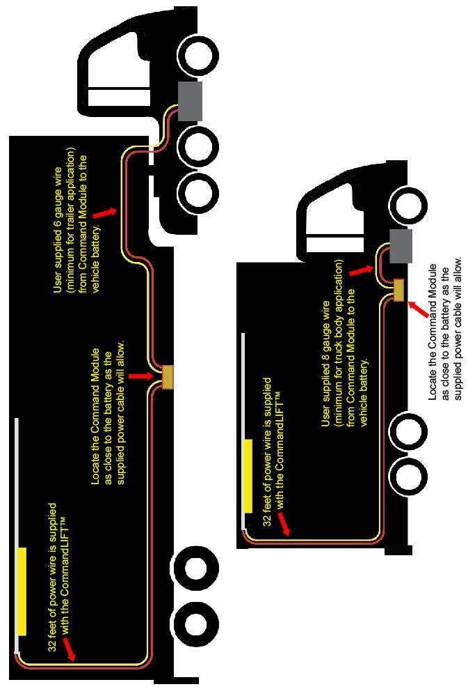
4 Before you start the installation This manual will cover the installation of two primary components, the CommandLIFT power door opener and if necessary an auxiliary power supply. We have used Purkeys Fleet Electric power supply which utilizes a Trail Charger charging system and a battery. The Purkeys installation is covered from page 30 through 44. The auxiliary power supply may be required for trailer applications. We do NOT recommend connecting the CommandLIFT to a reefer battery without first consulting with the reefer dealer and Whiting technical support. POWER REQUIREMENTS: The CommandLIFT is supplied with 32 feet of cable that runs from the CommandLIFT track to the Command Module that should be mounted as close to the supply battery as possible. The installer is required to supply the main power wire that runs from the 12 volt, 20 amp power supply (battery) to the Command Module. An 8 gauge supply wire can be used if this wire is less than 35 feet in length. This would typically be used in a truck body application. If the supply wire is 35 feet to 60 feet in length, then a 6 gauge wire must be used. See the illustration on the next page. WARNING The gauge of the supplied cables is determined by the maximum possible lengths. Do not splice wires for extra length as this can cause voltage drop resulting in poor / intermittent operation or damage to the system. Power Consumption: An idle CommandLIFT will draw 1.2 amp hours from a battery over a 24-hour period. It is recommended that during long periods of inactivity, the CommandLIFT be disconnected from the battery. 1. Using the illustration on the next page, plan how you are going to run the wires for the CommandLIFT. 2. Note that the CommandLIFT Module must be located as close as possible to the source battery. If the cable lengths do not allow this the CommandLIFT module can be mounted under or inside the vehicle. It must be protected from the extreme conditions under the vehicle. It is not recommended, but if you are planning to connect the CommandLIFT to an existing Reefer Unit or Lift Gate consult with Whiting Door and the reefer / lift gate supplier first! Today s refrigeration units are equipped with sophisticated electronics and control systems. The integrated logic of these systems monitors the remaining power level of the battery and isolates accessories when the battery drops below pre-determined levels. It is strongly recommended that you utilize the Purkeys Trail Charger system to ensure your new CommandLIFT works consistently and doesn t depend on the refrigeration system for power. IMPORTANT! ALWAYS MOUNT BOX WITH WIRE OPENINGS TO THE BOTTOM. 4
5 5

6 Insulated Truck Bodies or Trailers If the CommandLIFT is going to be installed in an Insulated truck body or trailer, you must ensure that strips of wood or metal spacers are securely fastened to the roof bows and extend down to the ceiling of the body. Do NOT fasten the CommandLIFT aluminum track to the insulation in the ceiling. This will not be strong enough to support the weight and the force that is required to open and close the door. Twin Spring Balancer Maintenance The CommandLIFT was designed to operate with any WHITING roll-up door, provided the door is equipped with a twin spring balancer and the door has been properly maintained and balanced. The CommandLIFT can also be used with other roll-up door systems but some modifications to the trailer or truck body header may be required. Check to make sure the roll-up door is properly balanced. The CommandLIFT will operate the roll-up door provided a force of no more than 50 pounds is required to open or close the door. Ensure that the force required to lift the door is the same force required to close the door. If the door requires more force to open than it does to close, increase the tension on the balancer. If the door requires more force to close than it does to open, decrease the tension on the balancer. Time and the elements affect the tension on the spring that lifts the door. Over time, the spring wire will corrode and loose effective wire diameter. The springs themselves also get tired and loose their tensile strength. An average balancer on a WHITING door will last approximately 15,000 to 25,000 cycles. If your roll-up door is NOT in proper balance, follow the procedure on the next page. 6
7 Adjusting and Maintaining the Proper Door Balance Always lubricate your roll-up door using WHITING Easy-UP spray lubricant prior to checking the balance of the door. NOTE: If the door is balanced before it is lubricated, it will have to be over balanced in order to overcome the friction of dry rollers and hinge pins. 1. Fully open the roll-up door and push it back towards the front of the trailer approximately 18, this may require the assistance of another person or a spreader bar placed between the header and the bottom panel of the door. 2. Install vice grip pliers into the track at the bottom roller to hold the door in this open position while working on the balancer. 3. The springs should have equal tension, for this reason it is important to count the number of turns either put on or removed from each spring, this is easily done by placing a mark on the winding anchor before doing any adjustments. 4. Insert a 3/8 diameter rod (see illustration on previous page) into one of the holes on the winding cone` and carefully loosen the set screws. Lower the winding bar to add tension or raise the winding bar to remove tension. Insert the second winding bar into the next hole on the winding anchor and repeat the process until the desired tension is achieved. The amount of tension to be added or removed depends on the type of door, the age of balancer and how far out of adjustment it is. Adjust the springs no more than one half turn at a time. 5. Tighten all the set screws and remove the winding bars 6. Repeat this procedure on the other Balancer spring. Be sure to add or remove the same amount of tension as you did on the first side. 7. Remove vice grip pliers from track and test the door operation. Caution work on doors and related parts can be dangerous. It is strongly recommended that repair service work be performed by persons who have successfully completed appropriate training. If assistance is required, please contact WHITING for a list of qualified service locations. 7

8 Mounting the Door Plate 1. Measure the width of the roll-up door and mark the centerline of the door on the top panel. 2. Rest the mounting plate on the top of the door and slide the plate left or right until the connecting tab lines up with the centerline of the door. 3. Use the mounting plate as a template and drill only the five (5) holes shown below, in the door panel and mount the plate with the fasteners provided. Note: Some composite and hollow doors will require additional mounting hardware in order to provide extra strength for the installation of the door plate assembly. This additional hardware is only included in CommandLIFT kits that are manufactured for these types of doors. Line up with Centerline Of Door Changing the Top Roller Brackets 8
. 1.")

9 WHITING DryFREIGHT style roll-up doors come equipped with regular top closure assemblies (shown to the right). It is necessary to replace these assemblies with the adjustable top closure slide arm and bracket assemblies that are included in the CommandLIFT box (See Illustration below). 1. Fully close the roll-up door. 2. Using a 1/2 wrench, remove the nuts from the existing top closure slide brackets. DryFREIGHT Top Closure Assembly 3. Replace the brackets with the adjustable top closure arm and bracket assemblies and rollers. 4. Make sure the brackets are installed so that the top panel of the roll-up door pushes against the header to ensure a good seal when the door is closed. Check to make sure the top door panel clears the Balancer Brackets. Note: It is not necessary to change these brackets if you are installing the CommandLIFT on the WHITING ColdSAVER or the TempGUARD doors. Changing the Balancer Center Bracket 9

10 1. Using a 1/2 wrench, undo the two nuts on the Balancer Center Bracket that is located at the mid point of the WHITING balancer. 2. Insert a 3/8 diameter rod into one of the round holes on the Balancer spring winding cone. Hold this rod tightly so the balancer spring does not unwind when the Balancer Center Bracket is removed. 3. Remove the old Balancer Center Bracket and replace it with the one in the CommandLIFT box. 4. Tighten the 1/2 nuts and confirm that the door is still properly balanced. Note: This step can only be done if the roll-up door operates with two balancer springs as shown above. If your door only has one balancer spring, you will have to make any necessary modifications in order to fasten the CommandLIFT track firmly to the header. Joining the two lengths of CommandLIFT aluminum track together. 10

 that are holding the joiner slides in the rear track section. 4.")
11 Depending on how your CommandLIFT was ordered, the aluminum track will be shipped in either one or two pieces. If the track was delivered in one piece, continue on to the next step: Connecting the track to the Header Bracket. If the track was delivered in two pieces, follow the next steps to join the two tracks together. 1. Remove the black plastic cover from the side of both track sections. 2. Line up the two pieces of track on a straight, level bench or work surface. 3. Using an Allen wrench, undo the six screws (both sides) that are holding the joiner slides in the rear track section. 4. Pull the two track joiners halfway out of the rear track section and lightly tighten the two front screws 5. Slide the front track over the two joiner pieces and ensure that the two tracks are butted together snugly. 6. Make sure the two tracks align properly and there are no sharp edges at the joint. Sharp edges at this location will cause premature wear to the motor sliders. 7. Tighten down all the screws and once again, check for fit and alignment. 8. Find the Sensor wire that has been pre-installed on the front track section, and connect it to the Sensor that is located in the rear track section. The position of this sensor will probably have to be adjusted later in the installation. 9. Fit the wire carefully into the track sections. This Sensor determines how far the door will open. If the length of the aluminum track has to be reduced for any reason, the cut must be made at the back of the track (furthest from the door opening). Replace the Stop Screw that was cut off of the track. The shortest length of track required for the CommandLIFT to operate properly is: door height plus 36 inches. Connecting the track to the Header Bracket 11


12 Connecting the track to the header 1. Pick up the front of the CommandLIFT track assembly and fasten the adjustable mounting bracket to the Balancer Center Bracket that you installed on the Balancer shaft in the previous step. 2. Place the 5/16 nut and bolt through the three pieces and finger tighten the nut. All the nuts in this area will be tightened later. Adjustable Header Bracket 3. Adjust the Header Bracket left or right to ensure the tab on the top door panel and the tab on the CommandLIFT motor unit are lined up as closely as possible. Once the two tabs are lined up, tighten the adjusting bolts in the Header Bracket so the track assembly won t move while it is being fastened to the ceiling or roof bows. Fastening the CommandLIFT track to the roof bows 12
. 3.")

13 1. Using Jack Stands or some other suitable method, lift the front end of the CommandLIFT track up to the ceiling or roof bows. 2. Measure from the edge of the body roof to the edge of the CommandLIFT track (at the header). 3. Adjust the other end of the track and confirm that the same measurement is used along the entire length of the track. 4. Tighten the stands to ensure the track will not move while it is being fastened to the roof bows. It is critical that the CommandLIFT be installed parallel to the sides of the Trailer or Truck Body. 5. Using a suitable bit, drill holes in every roof bow along the entire length of the CommandLIFT track. 6. Use the two grooves in the track to locate the positioning of your fasteners. 7. Use two fasteners at every roof bow. 8. A large diameter head screw or rivet, with a head depth of less than 1/4 is recommended. Drilling the roof bows 13
 10.")
14 Access Panel 9. Open the black Access Panel on the motor unit and you will see a metal lever. Insert a screw driver in the hole on this lever and pull the lever towards the roll-up door. This will release the motor unit from the gears and will allow the motor unit to slide freely along the track. (See the illustrations above) 10. Slide the CommandLIFT motor unit (by hand) along the entire length of the track. Watch and feel for any obstructions or resistance during the travel. Make sure the fastener heads are not too large and pay particular attention to any waving in the track. If the CommandLIFT binds because of a wavy track, use shims to make sure the track is level and straight. 11. Once the track is secure and straight, tighten all the nuts and fasteners at the Header Bracket. Tighten all fasteners 14

15 Connecting the CommandLIFT to the Roll-Up door 1. Slide the CommandLIFT motor unit towards the door, as far as it will go, then slide it back approximately 3/4 inch. 2. Make sure the roll-up door is in the fully closed and locked position. 3. Measure the distance between the hole in the tab on the Motor Unit and the hole in the tab on the Door Plate and cut the threaded connector rod 1 shorter than this measurement. 4. Install the turn buckle. Tighten the nut on the threaded rod up against one of the forks on the assemble to prevent the rod from turning itself out from vibration. 5. The turn-buckle assembly should be resting at approximately 45 degrees. 6. Open the roll-up door by hand and confirm that everything operates smoothly. Drilling the Holes for the Emergency Release 15
 panel. 2. Find the paper template in the CommandLIFT box.")

 completely through the door panel B 1/4 diameter These are clearance holes and should be drilled no more than 1/4")
16 Line up this edge of template with the centerline of the second door panel CommandLIFT Installation Manual with auxiliary power supply. 1. Measure the width of the roll-up door and mark the centerline of the door on the second (from the top) panel. 2. Find the paper template in the CommandLIFT box. Remove the paper backing and stick the template to the second panel as described in the illustration on the next page. Not to Scale B Line up this edge of template with the top edge of the second door panel A C A B Second door panel from the top. 3. Drill holes A, B and C as per the chart below. Hole Drill Diameter Notes A 3/8 diameter Drill holes (2) completely through the door panel B 1/4 diameter These are clearance holes and should be drilled no more than 1/4 deep. (Do NOT drill completely through the door panel). C 7/8 diameter Use a hole saw and drill hole through the door panel 4. Remove the template from the door panel if you wish, or mount the plate directly over the template. Connecting the EMERGENCY release cable 16


17 1. Locate the lock assembly, turn the key 90 degrees and remove the core of the lock from the lock housing plate. Insert the housing plate into the holes on the face of the door. Use masking tape if necessary to hold the housing to the face of the door. 2. Select the appropriate length screw from the chart and secure the interior mounting plate to the housing, ensuring the small holes on the corners are aligned with the relief holes. 3. Insert the end of the cable with the stop into the guide tube at end of the motor housing, push the cable through until you can see it in the opening where the lever is. Insert the stop through the release lever and engage the lever (lock the CommandLIFT), with the lever engaged push the cable 2 further into the motor. 4. Slide the cable sleeve over the cable and into the motor housing 2. Mark the sleeve 1 below the door connector plate. Remove the sleeve and cut it on the mark. DO NOT CUT THE CABLE. Slide the sleeve back over the cable and into the motor housing. Use the two ½ Phillips machine screws to secure the cable clamp to the door connector plate. 5. Ensure the cable is still two inches past the release lever and the lever is still engaged. Using good quality cutters cut the cable 1 below the lock mounting plate. Not using a proper tool to cut the 17


18 stainless cable can cause the end of the cable to fray and become difficult to insert into the lock. 6. Slide the yellow tube, the 2 piece of cable sleeve and the plastic cover base over the cable. Push the cable through the door and lock housing so it protrudes through the face. 7. Insert the cut end of the cable into the hole on the back of the lock core. Secure the cable by tightening the set screw on the side of the core with a 5/64 Allen key. Be sure it is a tight as possible. Insert the core into the housing, turn 90 degrees and remove the key. 8. Use the two screws provided to secure the exterior cover over the lock assembly. 9. Locate and secure the rear cable cover on the mounting plate using the two 1 Phillips machine screws provided. This cover also acts as a clamp for the 2 section of cable sleeve. Routing the Supply Wires to the Command Module The CommandLIFT is supplied with a 32 foot, 6-wire power cable, which has been preconnected to the CommandLIFT track at the factory. 18


19 The Command Module (electronic box) should be located as close as possible to the 12 volt, 20 amp power source as possible. In a typical installation, the power cable might run along the header, and down along the side wall. From there, the cable would be routed under the truck body or trailer as far forward as the cable will allow. At this point, find a safe and convenient location to mount the Command Module box. Even though the Command Module box has an NEMA 4X rating, it should be located in as protected a location as possible. Inside the control module you will find 2 key fobs and 4 mounting tabs. The key fobs are programmed for this box, do not mix them up with fobs from other units. Install the mounting tabs on the back of the module with the 4 screws provided. (as shown) There is a wire gland and two power feed bolts on the bottom of the Command Module box. Be sure to mount the box with the wire openings towards the bottom. Mount the box onto the vehicle. Route the cable from the CommandLIFT up through the cable gland. Ensure there is enough wire to reach the far side of the terminal strip inside the box. Tighten the nut. This nut has to be tight enough to provide a water-tight seal around the wire. Two wires will be required to connect the Command Module to the battery. These two wires are not included with the CommandLIFT. If installing the module inside the battery enclosure 10 gauge wire is adequate, if mounting the module outside the enclosure minimum 8 gauge wire is required for up to 35 feet in length. Over 35 feet will require 6 gauge wire. NEG FEEDER BOLT POS FEEDER BOLT COMMANDLIFT CABLE GLAND A 30 amp in line fuse should be used on the positive line as close to the battery as possible. This will protect the vehicles electrical system and prevent a fire in the event that a dead short situation occurs. NOTICE - Using supply wires of a smaller gauge than mentioned above may result in the CommandLIFT not operating properly and may damage the system and void the warranty. 19

20 Wiring the Command Module The CommandLIFT cable contains six wires. The white, yellow, brown and green wires are smaller gauge than the red and black wires. Study the illustration to the right, and route the smaller gauge wires to the terminal strip and connect the white wire to the existing white wire, the yellow wire to the existing yellow wire, the brown wire to the existing brown wire and the green wire to the existing green wire. The red and black wires should be connected to the existing red and black wires at the end of the terminal strip. Make sure all connections are solid and secure. The two battery wires can now be connected to the feeder bolts on the bottom of the box. If you have elected to use different colored battery wires, make sure that the POSITIVE wire is connected to the red feeder bolt and the NEGATIVE wire is connected to the black feeder bolt and the opposing ends are identified as positive and negative. Cover the bolts with a die electric grease or other type of protection from the elements. Connecting to the 12 volt battery source When you are satisfied that all the connections to the Command Module are tight and secure you can now connect the source cables to the battery. Make sure the positive lead from the Command module is connected to the positive post on the battery and the negative lead is connected to the negative post on the battery. Make sure these connections are secure. Protect the connections from the elements by applying die electric grease or some other type of sealant to the connections. Engage the Motor Unit and test the door 20

21 Before engaging the motors, position the door so the CommandLIFT is between the open and closed sensors. These are found on the road side of the CommandLIFT track. Once the CommandLIFT is between these sensors you can lock the motor into position by engaging the drive lever. Open the black access cover on the motor unit and you will see a metal lever. Insert a screw driver in the hole on this lever and pull the lever towards the front of the body (away from the door opening) until the lever SNAPS into place at the location shown to the right. You may have to use a screw driver or other suitable tool to help you move the lever into place. The motor unit is now locked into place in the track. Replace the access cover. Check the installation of the CommandLIFT once again, and when you are satisfied that the installation is complete, and all the fasteners and electrical connections are tight and secure, press the button on the Remote Control transmitter. The door will operate. Pressing this button again, will STOP the door travel. Adjust the door travel 21


22 SENSOR CABLE SLIDER On the road-side of the aluminum track, you will see two Sensor Units that are each held in place with a set screw. You will have to remove the plastic, finishing strip from the aluminum track in order to see these Sensors. These Sensor Units tell the CommandLIFT how far to travel before stopping by sensing the magnet inside the cable slider. To set the Sensor for the door CLOSED position, close the door all the way and slide the sensor so it rests just above the cable slider. The LED light indicating door closed should be illuminated in the Command module. To set the Sensor for the door OPEN position, open the door all the way. Loosen the set screw on the OPEN Sensor and slide it in the aluminum track until it rests about 2 in front of the cable slider. In the OPEN position, the roll-up door should be just clear of the header. This will provide a FULL door opening on the truck body or trailer. The door open LED on the board should be illuminated. Don t forget to place the CommandLIFT CAUTION label above the door grab handle, just above the Pull Strap. This label reminds operators that the door will probably not operate normally and that they must use the Remote Control Transmitter in order to activate the door, or use the key on the EMERGENCY Release system in order to operate the door manually. 22
 for fifteen minutes. 2.")
23 What happens when the Remote Control Transmitter button is pressed? 1. When the Remote Control Door Button is pushed, the door will start to open. After the door is in the open position, the LED lights on the CommandLIFT motor unit will turn on. The lights will stay on (with the door open) for fifteen minutes. 2. When the Remote Control button is pressed again, the door will close. After the door is in the closed position, the LED lights on the CommandLIFT motor unit will turn on and will stay on for one minute. 3. If you press the Remote Control button while the door is in travel either up or down, the door will STOP. The next time the button is pushed, the door will travel in the opposite direction. 4. If the roll-up door hits an object (such as a box or other cargo) while it is closing, the door will stop moving and go back up approximately three inches allowing the obstacle to be removed. The next time the Remote Control button is pressed, the door will go back to the fully open position. If the door is obstructed while opening it will stop, but not reverse. The next time the remote is pressed the door will go back down to the fully closed position. 5. Make sure the roll-up door lock is in the UNLATCHED position before the CommandLIFT is operated. 23


24 Using the EMERGENCY Key Release system You may be occasionally required to release the CommandLIFT from the door system in order to operate the Roll-Up door manually. CommandLIFT can be released from the drive system in two ways. Using the exterior EMERGENCY release 1. Insert the CommandLIFT key into the lock cylinder located in the center of the second roll-up door panel from the top. 2. Turn the key 90 degrees and pull the lock and connecting cable from the lock cylinder. Pull the lock assembly firmly and the CommandLIFT will be released from the drive system. 3. Reinsert the cable and the lock cylinder back into the lock housing on the door. The roll-up door can now be operated manually. Using the interior EMERGENCY release 1. Pull on the yellow section of the cable coming from the CommandLIFT to the door. 2. Now the door can be operated manually. Reconnecting the CommandLIFT drive system 1. Open the Access Panel on the CommandLIFT motor unit. 2. Pull the lever towards the front of the body (away from the door opening) until the lever SNAPS into place at the location shown to the right. You may have to use a screw driver or other suitable tool to help you move the lever into place. The motor unit is now locked into place in the track. Replace the cover on the access panel. CommandLIFT can now be operated with the Remote Control transmitter. 24
25 Integrating Auxiliary Systems with CommandLIFT Integration of the CommandLIFT system with other operating systems may only be done with express written consent of WHITING Door. Failure to do so will void all warranties. Consult with your dealer or the factory before connecting any other systems to the CommandLIFT controller. Conditions Connection must be as outlined in the CommandLIFT manual as well as the specific installation instructions from the integrated accessory. WHITING warranty against manufacturing defects is limited to the CommandLIFT motor unit, the control module and any supplied cable. WHITING Door will not be held responsible for any components or related labour to any auxiliary systems as a result of integration with the CommandLIFT. Damage to the CommandLIFT controller as a result of connection to an auxiliary controller is not covered and is the responsibility of the supplier / manufacturer of the secondary controller. Under no circumstances can the CommandLIFT control module be used as a power source or junction point for any auxiliary systems or controllers. Damage to the mechanical drive system, track, electronic module or wiring through improper operation of the CommandLIFT in conjunction with any auxiliary systems is not covered under warranty. Any damage as a result of forcible entry is not covered under the warranty. WHITING Door reserves the right to review and retract if necessary the consent if the configuration of the various systems deviates from the original design and approval. Troubleshooting with Auxiliary Systems When CommandLIFT is used with a controller other than the originally supplied CommandLIFT FM receiver the first step in any troubleshooting scenario is to check for power to the CommandLIFT controller and auxiliary controller. Once power has been verified the second step is to disconnect the auxiliary inputs to the CommandLIFT controller and reinitiate the FM receiver. Test the CommandLIFT with the originally supplied receiver and key fob remotes. If the CommandLIFT works with the original receiver and remotes the problem is with the auxiliary system. Contact the supplier / manufacturer of that system. 25

26 Programming Additional Remote Control Transmitters The CommandLIFT comes with two Remote Control transmitters that are pre-programmed for your motor unit. The CommandLIFT will allow additional Remote Control transmitters to be programmed to the motor unit. These additional Remote Control transmitters must be programmed into the CommandLIFT system by following these steps: 1. Open the cover from the CommandLIFT Electronic Command Module. 2. Locate the small WHITE button shown with the Red arrow. 3. Press the WHITE button briefly and the small RED light will glow. 4. While the RED light is ON, press the button on the new Remote Control transmitter. Press this button again and the RED light will go out, the new transmitter is now programmed for your motor unit. Press the button again and the door will operate You can also erase the CommandLIFT memory of all the programmed transmitters and reprogram a new set of transmitters by following these steps: Press and hold the WHITE button approximately 10 seconds. Release the button and the small RED light will flash 5 times. All memory of existing transmitters has been erased. Follow Steps 2 to 4 above and the new transmitters will be programmed for your system. WHITE PROGRAMMING BUTTON RED LED INDICATOR LIGHT 26


27 Changing the Battery in the Remote Control Transmitters If the Roll-Up door does not operate when the button on the remote control transmitter is pressed, check the Blue light on the transmitter to make sure it is working. If the Blue light flashes, or does not light at all, then the battery in the transmitter needs to be replaced. 1. Using a small Phillips screwdriver, carefully remove the three small screws from the back of the transmitter housing and remove the rear cover of the transmitter. 2. With the cover removed, you will see the two CR2016 button cell batteries. Carefully remove the batteries from the transmitter and replace them. Make sure to replace the batteries in the same orientation as they were removed. + facing up. 3. After replacing the cover, confirm that the Blue light on the on the transmitter is working properly. The Remote Control does NOT need to be reprogrammed. CommandLIFT Maintenance There are only a few maintenance procedures that should be completed on a monthly basis. 27

28 1. Using WHITING brand EASY-UP spray lubricant, completely lubricate the EMERGENCY key lock located on the Roll-Up door. 2. Inspect and clean the Aluminum track. If the track assembly was shipped in two pieces, make sure the track joint is flush and remove any sharp edges. 3. Make sure the Motor Unit slides smoothly in the track. 4. Check all the wiring connections to make sure they are clean, safe and secure. 5. Check the Plastic Motor Unit Guides and replace them if they show any signs of wear (see below). These Guides are available from a WHITING dealer. Ask for Plastic Motor Unit Guides Part No. CLA-0116 (Set of 4). Replacing the Plastic Guides on the Motor Unit 1. Remove the CommandLIFT Motor Unit from the aluminum track as per the directions on the next page. 2. Remove the four Plastic Motor Unit Guides from the Motor Unit housing. 3. Inspect the Plastic Motor Unit Guides and replace them if they show any signs of wear. Plastic motor unit guides Motor Unit removal for Servicing 28

 and you will see a metal lever.")

29 If the CommandLIFT has to be removed from the track for regular maintenance, follow these steps: Remove the Turn Buckle assembly from the motor unit. Remove the STOP screw from the track at the end furthest from the door opening. Remove the plastic End Cap from the Aluminum track at the end furthest from the door opening. Open the black access panel on the motor unit (see illustration to the right) and you will see a metal lever. Insert a screw driver in the hole on this lever and pull the lever towards the roll-up door. This will release the motor unit from the gears and will allow the motor unit to slide freely along the track. While the Access Cover is open, remove the EMERGENCY Release Wire Assembly from the motor unit. Remove the four screws from the black cover on the CommandLIFT Motor Unit. Unplug the two LED light wiring harnesses in the Motor Unit and slide the CommandLIFT Motor Unit out of the aluminum track (see illustration below). 29

30 Reinstall Motor Unit If the CommandLIFT was removed from the track for regular maintenance, complete the following steps to reinstall the CommandLIFT motor unit into the track. Slide the CommandLIFT motor unit back into the end of the aluminum track and reinstall the black End Cap assembly and stop screw to the aluminum track. Plug in the two wiring harnesses that are located in the plastic box on the motor unit (refer to illustration on the previous page). Replace the black plastic cover on the motor unit (see illustration below). Make sure the tab on the cover fits into the slot on the coil cable slider assembly, and replace the 4 mounting screws on the cover. Replace Cover Plate Appendix A - WHITING Roll-Up Door Maintenance Procedure 30


31 Lubricate the roller bearings and shafts, hinge pins and cable drum bearings as per the illustrations below. DO NOT USE GREASE OF ANY KIND! Grease sits on the surfaces and attracts dust, dirt and salt. The recommended lubricant is environmentally friendly, WHITING brand EASY-UP spray lubricant available from your local WHITING dealer Appendix B - 31
32 Mounting the Door Plate Note: Cable assembly is not as illustrated. Appendix C 32
33 Circuit board LED matrix. COMMANDLIFT LED MATRIX Circuit board wiring matrix. T3E OPEN/CLOSE/STOP INPUT COMMANDLIFT CONNECTION MATRIX This section of the manual deals with the installation of an auxiliary power supply. METHOD #1 33
34 Location of auxiliary battery box with Purkeys Trail Charger and CommandLIFT control module inside the enclosure, if the 32 foot CommandLIFT cable is adequate to reach the battery box. METHOD #2 Diagram below shows the CommandLIFT control module inside the trailer directly above the battery enclosure. This method may the best way to ensure the shortest wire lengths and offer the best protection to the module from the elements. Concerns about freight interference and bulkhead locations may be addressed by mounting the module close the rear condenser unit. METHOD #3 Diagram below shows the location of the CommandLIFT control module outside the battery enclosure if 32 feet of cable doesn t allow for installation inside the battery enclosure and mounting the module inside the trailer is not an option. The CommandLIFT control module should be mounted vertically and protected from flying debris. Battery life with a CommandLIFT 34
35 There are countless types of batteries that are available for the over the road market. Selecting the right type of battery for the CommandLIFT / Purkeys auxiliary power unit is critical for continued long term trouble free operation. Our recommendation is an AGM (absorbed glass mat) deep cycle battery. AGM (Absorbed Glass Mat) batteries require no maintenance. Deep cycle batteries can withstand deeper states of discharge with minimal effect on the overall life of the battery. The less a battery is discharged before being recharged increases the life expectancy of the battery. Ideally a deep cycle battery doesn t go below a 30% discharge rate. Meaning the battery is recharged at or above 70% capacity. Going below 70% doesn t have any adverse effects on the battery or performance; however going into that rate of depletion continually will reduce the overall life expectancy of the battery. For this reason a Group 31 battery is the recommended size. A Group 31 battery is rated at 95 to 125 amp hours. 105 amp hours was used for the calculations in the chart below. The chart below shows the daily requirements of a CommandLIFT at 12 amps draw, which is higher than typical, but possible in cold conditions. Using the chart below you can see that a Group 31 battery is suitable up to 300 cycles per day, which would be considered extremely unlikely. Complete Cycles (open and close) Accumulated Motor Run Time (minutes) Amp/hour Consumption Parasitic draw per day Total Amp Draw Battery Type Group 31 Group 31 Group 31 Group 31 Group 31 Remaining Capacity 94% 90% 81% 70% 61% It is imperative to determine the actual cycles per day to ensure the proper battery is provided. Using a starting battery or a battery that is under capacity can result in poor or intermittent operation of the CommandLIFT. Keep in mind that cold working environments increase resistance on the door resulting in higher amp draw, cold also decreases the battery s storage capacity and ability to recharge at a fast rate. 35
36 36
37 37
38 38
39 39
40 40
41 41
42 42
43 43
44 44
45 45
46 46
47 47
48 48
49 WHITING CommandLIFT LIMITED WARRANTY General Requirements All warranty herein extends to the original owner only and requires proof of purchase and installation of CommandLIFT Maintenance Kits at the first and second anniversaries of ownership. All warranty herein defines "warranty years" as the lesser of 12 months or 12,000 miles. CommandLIFT Kit Installed by an Authorized Whiting Shop Whiting CommandLIFT drive unit, electrical box & components, track and connecting rod & bracket are guaranteed against defective material and workmanship for a period of three (3) years. Proper installation and maintenance of the CommandLIFT is crucial for successful operation of this device. Any deviation from the CommandLIFT Owner's Manual immediately voids the warranty. Adequate power supply must be as outlined in the CommandLIFT Installation Manual and is required to maintain warranty. Installed by an Unauthorized Shop Whiting CommandLIFT drive unit, electrical box & components, track and connecting rod & bracket are guaranteed against defective material and workmanship for a period of one (1) year. Proper installation and maintenance of the CommandLIFT is crucial for successful operation of this device. Any deviation from the CommandLIFT Owner's Manual immediately voids the warranty. Adequate power supply must be as outlined in the CommandLIFT Installation Manual and is required to maintain warranty. Power Supply Power Supply Wiring All wiring, if supplied by Whiting, is guaranteed against defective material and workmanship for a period of one (1) year. Improper installation or hook-up voids the warranty. Any damage to the wiring sections is not covered. Genuine Whiting Parts and Components Use of anything other than Genuine Whiting parts or components voids the warranty. Installation of any non-whiting device or component to any part of the door kit voids the warranty. Installation Installation workmanship of the door kit is the responsibility of the party that performs the installation. Integration Integration of the CommandLIFT system with other operating systems may only be done with express written consent of Whiting Door. Failure to do so will void all warranties. Consult with your dealer or the factory before connecting any other systems to the CommandLIFT controller. This device complies with Part 15 of the FCC Rules. Operation is subject to the following two conditions: (1) this device may not cause harmful interference, and (2) this device must accept any interference received, including interference that may cause undesired operation 49


50 50
JEEVES. JEEVES Installation Manual. Installation Manual The Easiest Do-It-Yourself Dumbwaiter on the Market
 1 888-323-8755 www.nwlifts.com JEEVES Installation Manual The Easiest Do-It-Yourself Dumbwaiter on the Market This manual will cover the installation procedure step-by-step. The installation of this dumbwaiter
Premium Dry Freight (Plywood) Door Installation REFERENCE FIGURE 1
 Door Installation REFERENCE FIGURE 1") Premium Dry Freight (Plywood) Door Installation A Premium door can be identified as usually having a two-spring balancer, 2 diameter (nominal) rollers, and end hinges with removable covers. If your Whiting
Premium Dry Freight (Plywood) Door Installation A Premium door can be identified as usually having a two-spring balancer, 2 diameter (nominal) rollers, and end hinges with removable covers. If your Whiting
INSTALLATION INSTRUCTIONS
 INSTALLATION INSTRUCTIONS INSTALLATION INSTRUCTIONS THESE INSTRUCTIONS COVER THE INSTALLATION OF THE FOLLOWING REAR DOORS WITH OUTSIDE CABLES AND MAXIMUM SECURITY LOCK: 3/4" and 1" DryFreight TODCOLD Insulated
A B C D E F. Tools Required (supplied by others)
") Page 1 of 17 Parts List Below Deck Automatic Retractable Security Cover Kit (1) Tube End Bearing Plate (A) (1) Rope Reel and Cover Drum Motor Assembly (B) (1) Cover Drum (1) Pulley Support Channel (2)
Page 1 of 17 Parts List Below Deck Automatic Retractable Security Cover Kit (1) Tube End Bearing Plate (A) (1) Rope Reel and Cover Drum Motor Assembly (B) (1) Cover Drum (1) Pulley Support Channel (2)
Quick Install Lift AL065 Installation Guide & Owners Manual
 Quick Install Lift AL065 Installation Guide & Owners Manual Congratulations on your new lift purchase. The Quick Install Lift line is one of the easiest and most trouble free ways to transport your scooter
Installation Instructions Table of Contents
 Installation Instructions Table of Contents Pre- Installation of Garage Storage Lift 2 Layout the Garage Storage Lift 3 Installing the strut Channels 3 Install the Drive Assembly 5 Install the Drive Shaft
Installation and Service Manual
 RAVE Star Lift Installation and Service Manual WARNING! STRICT ADHERENCE TO THESE INSTALLATION INSTRUCTIONS is required and will promote the safety of those installing this product, as well as those who
Technical Support (707)
") Installation Instructions CONSOLE MEGASHIFTER Fits: 1982-1992 Camaro & Firebird w/automatic Transmission *except 1988-1992 Firebird Formula Model Catalog # 80692 WORK SAFELY! For maximum safety, perform
Installation Instructions CONSOLE MEGASHIFTER Fits: 1982-1992 Camaro & Firebird w/automatic Transmission *except 1988-1992 Firebird Formula Model Catalog # 80692 WORK SAFELY! For maximum safety, perform
HEAVY DUTY STAIR LIFT SYSTEM Installation and Service Manual
 HEAVY DUTY STAIR LIFT SYSTEM Installation and Service Manual WARNING! STRICT ADHERENCE TO THESE INSTALLATION INSTRUCTIONS is required and will promote the safety of installers, as well as those who will
ONE TOUCH CONTROL BOX
 ONE TOUCH CONTROL BOX CONVERSION KIT INSTRUCTIONS REMOVAL, INSTALLATION, OPERATION, AND REMOTE CONTROL PROGRAMMING THUNDERSTONE PART #101322 REVISION A JULY 14 TH 2016 2 P a g e INSTALLING THE THUNDER
Thunder Power Tarp Kit Operation. Dual Arm Curb Side Stowing Single Arm Curb Side Stowing Flex Arm Curb Side Stowing.
 Thunder Power Tarp Kit Operation Dual Arm Curb Side Stowing Single Arm Curb Side Stowing Flex Arm Curb Side Stowing 011-52475 Rev - 2 P a g e USE THE PROCEDURES BELOW TO OPERATE THE TARP SYSTEM Powering
A B C D E F. b.tools Required (supplied by others) 3/16" Drill Bit 3/8" Wrench Phillips Head Screwdriver
 3/16 Drill Bit 3/8 Wrench Phillips Head Screwdriver") Page 1 of 13 5E.1 Parts List a. Below Deck Automatic Retractable Security Cover Kit (1) Tube End Bearing Plate (A) (1) Rope Reel with Motor Attached (B) (1) Rope Reel Cover (C) (1) Cover Drum (1) Cover
Page 1 of 13 5E.1 Parts List a. Below Deck Automatic Retractable Security Cover Kit (1) Tube End Bearing Plate (A) (1) Rope Reel with Motor Attached (B) (1) Rope Reel Cover (C) (1) Cover Drum (1) Cover
GVW AGM Auxiliary Battery Kit for Air-cooled Westfalia Campers and all Vanagon NON-campers
 GVW-253-701AGM Auxiliary Battery Kit for 1980-1983 Air-cooled Westfalia Campers and all Vanagon NON-campers The purpose of this kit is to add an Interstate SLA1161 battery as an auxiliary battery under
SERIES A & AA ROLLER DOORS INSTALLATION GUIDE
 SERIES A & AA ROLLER DOORS INSTALLATION GUIDE THESE INSTRUCTIONS ARE PROVIDED FOR USE BY EXPERIENCED INSTALLERS OF GARAGE DOORS BY UNDER-TAKING THE INSTALLATION OF THIS DOOR, THE INSTALLER UNDERSTANDS
Installation Instructions PowerBoard Automatic Retracting Running Board WARNING WARNING WARNING. Support
 Installation Instructions PowerBoard Automatic Retracting Running Board Vehicle Application: Jeep Wrangler 2-Door 2007-2016 Part Number 75651-15 Installation Tips Read and follow, precisely, all installation
Automatic Roof Hatch Opener
 Automatic Roof Hatch Opener Installation Guide REQUIRED TOOLS (These tools are required to complete the installation) Cordless Drill 1/8 1/4 Drill Bits 1/8 Pin Punch #2 Philips Bit Rachet Sharpie Hammer
Installation Manual TWM Performance Short Shifter Cobalt SS/SC, SS/TC, HHR SS, Ion Redline and Saab 9-3
 Page 1 Installation Manual TWM Performance Short Shifter Cobalt SS/SC, SS/TC, HHR SS, Ion Redline and Saab 9-3 Please Note: It is preferable to park on a flat surface, as you will have to engage and disengage
Guide to Installing Y o u r H a r m a r S t a i r L i f t
 Guide to Installing Y o u r H a r m a r S t a i r L i f t 2 W E L C O M E T O T H E H A R M A R F A M I L Y Congratulations on your purchase of a Harmar Access Stairway Lift. These instructions will assist
INSTALLATION INSTRUCTIONS
 INSTALLATION INSTRUCTIONS POWER FRONT DISC CONVERSION KIT A126-7 1963-66 CHEVY C10 PICKUP NON-POWER FRONT DISC CONVERSION KIT A126-8 1963-72 CHEVY C10 PICKUP Thank you for choosing STAINLESS STEEL BRAKES
PORTABLE Q-CATCH 86 SERIES CHUTE, ALLEY & TUB PRODUCT MANUAL arrowquip.com
 PORTABLE Q-CATCH 86 SERIES CHUTE, ALLEY & TUB PRODUCT MANUAL 1-877-275-6075 cs@arrowquip.com arrowquip.com CONTENTS Safety Precautions 1 Risk Assessment 2 Q-Catch 86 Series Head Gate Assembly 3 Operating
INSTALLATION & OWNER S MANUAL
 Rev. E p. of 3 INSTALLATION & OWNER S MANUAL V446 Front Cab Kit and V446 Rear Cab Kit for RTV 40 INSTALLATION & OWNER S MANUAL The contents of this envelope are the property of the owner. Be sure to leave
Model 2300DL Installation Guide
 Model 2300DL Installation Guide POWER ACCESS CORPORATION 4 HERSHEY DRIVE, DOCK 4 ANSONIA, CT 06401 800-344-0088 WEBSITE: www.power-access.com EMAIL: salesinfo@power-access.com 1 STANDARD PARTS MODEL 2300DL
Owner s Manual And Guide To Installation
 Owner s Manual And Guide To Installation < # > TABLE OF CONTENTS 1 How to Use...3 1.1 Control Keypad...3 1.2 Mounting Hardware...4 1.3 Auto Launch Details...5 1.4 Trailering with the SWITCHBLADE...6 1.5
DEMOUNTABLE BODY INSPECTION PROCEDURE Follow Detailed Instructions Inside for Each Step
 DEMOUNTABLE BODY INSPECTION PROCEDURE Follow Detailed Instructions Inside for Each Step Inspection Date: Inspected By: Serial #: Unit #: INSPECT: Inspected OK Needs Repair Comments Front Locking Bar Rear
Thunder Power Tarp Kit Operation Guide
 Thunder Power Tarp Kit Operation Guide Dual Arm Curb Side Stowing Single Arm Curb Side Stowing Flex Arm Curb Side Stowing REV - B 1/13/17 2 P a g e USE THE PROCEDURES BELOW TO OPERATE THE TARP SYSTEM Powering
( Versions Available)
") STYLE 494 ELECTRIC LADDER PIPE INSTALLATION, OPERATING AND MAINTENANCE INSTRUCTIONS ( Versions Available) The following is intended to provide the basic instructions for installation, operating and maintenance
STYLE 494 ELECTRIC LADDER PIPE INSTALLATION, OPERATING AND MAINTENANCE INSTRUCTIONS ( Versions Available) The following is intended to provide the basic instructions for installation, operating and maintenance
Guide to Installing Your AMERIGLIDE Stairway Lift
 Guide to Installing Your AMERIGLIDE Stairway Lift 2 3 W E L C O M E O H E S U M M I F A M I L Y B E F O R E Y O U S A R Congratulations on your stair lift. hese instructions will assist you in making sure
<THESE INSTRUCTIONS MUST BE GIVEN TO THE END USER> B&W
 B&W Trailer Hitches 6 Hawaii Rd / PO Box 86 Humboldt, KS 66748 P:60.473664 F:60.869.903 Turnoverball Gooseneck Hitch Installation Instructions MODEL 08
Congratulations on your purchase of a Mobile Ramps and Lifts lift.
 2 W E L C O M E T O T H E M O B I L E R A M P S A N D L I F T S Congratulations on your purchase of a Mobile Ramps and Lifts lift. These instructions will assist you in making sure your installation is
Parkit360 Transformer
 Parkit360 Transformer 1 Owner s Manual Introduction We know you re busy, and need to get that fifth wheel moved. Now. So with that in mind, we ve kept these instructions as brief as possible, but they
Installation Instructions
 Installation Instructions AMP RESEARCH Power Step by Bestop Automatic Retracting Running Board Vehicle Application Nissan Titan King Cab 2004 and newer (5 ft.) Part Number: 75106-01 Nissan Titan Crew Cab
Model 2300JL Installation Guide
 Model 2300JL Installation Guide POWER ACCESS CORPORATION 4 HERSHEY DRIVE, DOCK 4 ANSONIA, CT 06401 800-344-0088 WEBSITE: www.power-access.com EMAIL: salesinfo@power-access.com 1 STANDARD PARTS MODEL 2300JL
Roller Shades MOTORIZED SHADE. Simplicity. Installation & Care Instructions
 Roller Shades MOTORIZED SHADE Simplicity Installation & Care Instructions 152140 J 1/13/2016 GETTING STARTED A few simple tools are required: - Measuring tape - Power drill, drill bits - 1 4 Hex head and/or
Alternator Removal and Installation Instructions
 Alternator Removal and Installation Instructions Removal CAUTION: Always use care when working on your vehicle! Do NOT disconnect any electrical cables or wiring while the engine is running! Make sure
PORTABLE Q-CATCH 86 SERIES CHUTE & ALLEY PRODUCT MANUAL arrowquip.com
 PORTABLE Q-CATCH 86 SERIES CHUTE & ALLEY PRODUCT MANUAL 1-877-275-6075 cs@arrowquip.com arrowquip.com CONTENTS Safety Precautions 1 Risk Assessment 2 Q-Catch 86 Series Head Gate Assembly 3 Operating the
DODGE RAM 2500
 81234007 2014-2015 DODGE RAM 2500 Congratulations - your new LevelTow Helper Springs are quality products capable of improving the handling and comfort of your vehicle. As with all products, proper installation
Roller Door Operator
 INSTALLATION INSTRUCTIONS AND OWNERS MANUAL Roller Door Operator IMPORTANT PLEASE READ THESE INSTRUCTIONS CAREFULLY PRIOR TO COMMENCING THE INSTALLATION OF THE OPERATOR UNIT CAUTION This Automatic Opener
Shaver Industries. Assembly Instructions Spring Assist Vertical Vinyl Curtain Door Projection Mount
 Shaver Industries 20 Steckle Place, Kitchener, ON N2E 2C3 Ph 1(888) 766 8328 www.shaverinc.com Assembly Instructions Spring Assist Vertical Vinyl Curtain Door Projection Mount Valued Shaver Customer: We
IVTM Installation Manual
 Integrated Vehicle Tire Pressure Monitoring IVTM Installation Manual 2nd edition Copyright WABCO 2006 Vehicle Control Systems An American Standard Company The right of amendment is reserved Version 002/06.06(us)
WirelessONE. Kit INSTALLATION GUIDE. Key Fob Activated Compressor System
 Kit 25870 Key Fob Activated Compressor System MN-751 (041202) ECR 7260 INSTALLATION GUIDE For maximum effectiveness and safety, please read these instructions completely before proceeding with installation.
JEEP JK4 STEP SLIDER INSTALLATION BD-SS-100-JK4
 JEEP JK4 STEP SLIDER INSTALLATION BD-SS-100-JK4 PARTS LIST QTY DESCRIPTION 1 Drivers Side Slider Assembly 1 Passenger Side Slider Assembly 1 Wiring Harness and Fuse 1 Double Sided Sticky Squares and Alcohol
Easy-On Wireless Tail Lights User s Guide
 Easy-On Wireless Tail Lights User s Guide TAKE NOTICE: BY INSTALLING OR OTHERWISE USING THE EASY-ON WIRELESS TAIL LIGHTS YOU AGREE TO FOLLOW THE BELOW DIRECTIONS CAREFULLY AND BE BOUND BY THE LIMITATION
Auto-Lift Operating System
 Installation Instructions Parasol Cellular Shades Auto-Lift Operating System CONTENTS Getting Started: Product View... 1 Tools and Fasteners Needed... 2 Installation: Installation Overview... 3 STEP 1
GENUINE Interior Lighting Kit
 GENUINE Interior Lighting Kit INSTALLATION INSTRUCTIONS Thank you for purchasing a genuine Mazda accessory. Before removal and installation, be sure to thoroughly read these instructions. Please read the
MOUNTING RAILS ***DO NOT EXCEED VEHICLE MANUFACTURER'S RECOMMENDED TOWING CAPACITY.***
 10/30/2017 PAGE 1 OF 6 Parts List ITEM QTY PART NUMBER DESCRIPTION 1 2 CM-16150-MR MOUNTING RAILS 2 2 CM-16150-FB.375" FRONT BRACKET 3 1 CM-16150-PSRB.375" PASSENGER SIDE REAR BRACKET 4 1 CM-16150-DSRB.375"
Guide to Installing Your Summit Stairway Lift
 Guide to Installing Your Summit Stairway Lift 2 3 W E L C O M E O H E S U M M I F A M I L Y B E F O R E Y O U S A R Congratulations on your purchase of a Summit Stairway Lift. hese instructions will assist
Installationn Instruction Manual
 Table of Contents Supplied Kit Parts.Page 2 Required Tool List Page 2 Step by Step Installation Instructions Pages 3-6 Battery Requirements.Page 6 Operation Page 7 Maintenance Page 7 Wiring Diagrams..Page
User s Manual. Automatic Switch-Mode Battery Charger
 User s Manual Automatic Switch-Mode Battery Charger IMPORTANT Read, understand, and follow these safety rules and operating instructions before using this battery charger. Only authorized and trained service
PowerLevel s e r i e s
 Owner s Manual Hydraulic Leveling CONTENTS Introduction Operation Control Panel Automatic Leveling Manual Leveling Retracting Jacks Remote Operation Care & Maintenance Troubleshooting Error Codes 1 2 2
CHECKLIST & COMPONENTS
 Eclipse Compact www.rollershuttercompany.com Tel 0800 6444121 55mm Roller Garage Doors CHECKLIST & COMPONENTS EQUIPMENT REQUIRED 2 x Step ladders or hop ups Spirit level Tape measure Power drill 10mm A/F
SUT-250-S (These instructions are used for SUT-250-SCLC also)
") SUT-250-S (These instructions are used for SUT-250-SCLC also) Torque wrench, carpenters square, wire cutters, Phillips screwdriver, 7/16, 9/16, and 3/4 combination wrenches, ratchet, 9/16, 3/4, 13/16,
SUT-250-S (These instructions are used for SUT-250-SCLC also) Torque wrench, carpenters square, wire cutters, Phillips screwdriver, 7/16, 9/16, and 3/4 combination wrenches, ratchet, 9/16, 3/4, 13/16,
Thunder Power Tarp Kit Operation
 Thunder Power Tarp Kit Operation Dual Arm Curb Side Stowing Single Arm Curb Side Stowing 011-52476 Rev. H P a g e 2 In this booklet you will find: OPERATING INSTRUCTIONS... 3 Powering up or down the system...
Installation and Service Manual
 RAVE Stair Lift Installation and Service Manual WARNING! STRICT ADHERENCE TO THESE INSTALLATIONS INSTRUCTIONS IS REQUIRED to promote the safety of those installing this product, as well as that of those
Ford Mustang V6 OEM-Style Fog Light Kit Parts List: Quantity: Tool List:
 2015-2017 Ford Mustang V6 OEM-Style Fog Light Kit Parts List: Quantity: Tool List: LED Foglights/ Bezels 2 Flat head & Phillips screwdriver (if you ordered part#3600) Ratchet & Socket set OR Wiring harness
IMPORTANT! Remote Control Instructions
 Remote Control Instructions FOR New Tarp Remote Control Installation Use these in place of the rocker switch and solenoid section of instructions in your roll tarp owner s manual. FOR Existing Electric
BOLT-ON AND WELD-ON FLUSH FLOOR SLIDEOUT SYSTEMS OPERATION AND SERVICE MANUAL
 BOLT-ON AND WELD-ON FLUSH FLOOR SLIDEOUT SYSTEMS OPERATION AND SERVICE MANUAL TABLE OF CONTENTS SYSTEM...... Warning........ Description...... Prior to Operation OPERATION... Main Components... Mechanical...
The USAutomatic Electric Gate Lock Assembly works with most types of gates and mounting applications.
 USAUTOMATIC ELECTRIC GATE LOCK Part Number 070510 Installation Manual The USAutomatic Electric Gate Lock works with an automatic gate operator to securely lock the gate into position without having to
Installation & Programming Manual. Quick Reference
 Installation & Programming Manual Getting Started Prepare door, per additional instructions (included) before installing unit. IMPORTANT: Read instructions completely before beginning installation. Refer
SERIES B & C ROLLER DOORS INSTALLATION GUIDE
 SERIES B & C ROLLER DOORS INSTALLATION GUIDE THESE INSTRUCTIONS ARE PROVIDED FOR USE BY EXPERIENCED INSTALLERS OF GARAGE DOORS BY UNDERTAKING THE INSTALLATION OF THIS DOOR, THE INSTALLER UNDERSTANDS THE
Installation and Service Manual
 RESIDENTIAL PLATFORM LIFTS RPL400 / RPL600 Installation and Service Manual WARNING! STRICT ADHERENCE TO THESE INSTALLATION INSTRUCTIONS IS REQUIRED to promote the safety of those installing this product,
Installation Instructions
 patent pending Portable Proportional Braking System Installation Instructions Part number 9400 Towing and Suspension Solutions ROADMASTER, Inc. 6110 NE 127th Ave. Vancouver, WA 98682 800-669-9690 Fax 360-735-9300
Easy Cover. Installation Instructions. Attention Dealers: Please give this owners manual to the customer when the product is delivered.
 Serving the Truck & Trailer Industry Since 944 Easy Cover Attention Dealers: Please give this owners manual to the customer when the product is delivered. Call 00-3-94 www.aeroindustries.com Indianapolis,
Alliance Towel Dispensing System. Operation Manual
 Alliance Towel Dispensing System Operation Manual Alliance Towel Dispensing System Table of Contents Safety Information... page 2 Mounting Instructions... page 3 Towel Loading Instructions... page 7 Settings...
INSTALLATION & OWNER S MANUAL
 Rev. B, p. 1 of 25 INSTALLATION & OWNER S MANUAL POLARIS RANGER RCS (for models XP or HD) (for model years 2009-) cab without doors kit (p/n 1POLRCWD) cab with doors kit (p/n 1POLRC) doors only kit (p/n
Installation Instructions. QuickSilver Shifter. Fits: GM, Ford, Chrysler Transmissions See Application Guide for Specific Applications Part # 80683
 Installation Instructions QuickSilver Shifter Fits: GM, Ford, Chrysler Transmissions See Application Guide for Specific Applications Part # 80683 WORK SAFELY! For maximum safety, perform this installation
INSTALLATION INSTRUCTIONS TRAILER HITCH MAIN HARNESS KIT
 PART NUMBER: 0000-89-N30 GENUINE ACCESSORIES INSTALLATION INSTRUCTIONS TRAILER HITCH MAIN HARNESS KIT APPLICABLE MODELS: 2016 > CX-9 PACKAGE CONTENTS: INSTALLATION INSTRUCTIONS QTY 1 CABLE TIE MOUNT QTY
Assembly Instructions
 Assembly Instructions Part Number Description Model Approx. Assembly Time 99994-0903 Windshield Wiper Kit Mule SX 1 Hour WARNING Improper installation of this accessory could result in an accident causing
Installation / Operating Manual. Infinity Series Model AS2002. Distributed by: Shyda s Services Inc.
 Installation / Operating Manual Infinity Series Model AS2002 Distributed by: Shyda s Services Inc. WARRANTY: INFINITY SERIES MODEL AS2002 For two(2) years from the original date of purchase, Lincoln Traps
INSTALLATION INSTRUCTIONS
 28 INSTALLATION INSTRUCTIONS SECTION - AIR SPRING SECTION 2 - AIR ACCESSORY 2-5 ! IMPORTANT PLEASE DON T HURT YOURSELF, YOUR KIT OR YOUR VEHICLE. TAKE A MINUTE TO READ THIS IMPORTANT INFORMATION. This
INSTALLATION INSTRUCTIONS
 2807 INSTALLATION INSTRUCTIONS SECTION - AIR SPRING SECTION 2 - AIR ACCESSORY -6 ! IMPORTANT PLEASE DON T HURT YOURSELF, YOUR KIT OR YOUR VEHICLE. TAKE A MINUTE TO READ THIS IMPORTANT INFORMATION. This
Customer Name: Serial Number: Y-Axis Stall
 Technician Name: Date: Technician Name: Date: Customer Name: Serial Number: Y-Axis Stall Issue Explanation and Background Each drive motor on the machine (the x, y and z axes motors) has a sensor called
Rear Roll-up Door. W-Series
 Door, W-Series Rear Roll-up Rear Roll-up Door W-Series Service Guide Do NOT use the rear door pull strap to support yourself when entering or exiting the rear. The strap can break or pull the door down
Helix Curved Stair Lift Installation & Service Manual
 Helix Curved Stair Lift Installation & Service Manual WARNING! Strict adherence to these installation instruction IS required to promote the safety of those installing this product, as well as that of
AL625 & AL625HD INSTALLATION & OWNER S MANUAL
 AL625 & AL625HD INSTALLATION & OWNER S MANUAL These instructions are provided to assist you in the installation of the AL625. If you require further assistance, our trained staff is ready to provide you
C15C C15C. Page 1 of 20
 2 x Lid Front Hinge 1135 8 x M8 Bolt 8 x M8 Washer (3mm Thick) 4 x M6 Large washers 4 x M6 Spring washers 4 x M6 x 40mm Bolts 6 x M6 20mm Bolts 6 x M6 Washers 20 x Screws 2 x Lid mount gas strut bracket
Southwest Windpower Instruction Sheet AIR-X Circuit Replacement Kit
 Southwest Windpower Instruction Sheet AIR-X Circuit Replacement Kit Tools Required 5 / 32 Hex key 5 / 16 Hex key 7 / 64 Hex key Standard screwdriver Pair of external snap ring pliers Rubber mallet Hammer
Milano AUTOMATIC FAUCET
 Milano AUTOMATIC FAUCET with Surround Sensor Technology Installation & Maintenance IMPORTANT: PLEASE READ ENTIRE INSTRUCTION BOOKLET BEFORE YOU BEGIN INSTALLATION! Looks Clean - Is Clean. AutoFaucet Parts
DrVanos.com Stage II Installation Instructions. Tool rental is available with the purchase of a vanos kit *See website for more info*
 DrVanos.com Stage II Installation Instructions Special Tools Needed: Camshaft locking tool TDC Crank pin Sprocket turning tool Tool rental is available with the purchase of a vanos kit *See website for
INSTALLATION INSTRUCTIONS
 INSTALLATION INSTRUCTIONS REAR DISC CONVERSION KIT A128-4 1997-2004 JEEP WRANGLER (TJ) WITH DANA 44 AXLES (non-abs) Thank you for choosing STAINLESS STEEL BRAKES for your braking needs. Pleases take the
Components. Options Accessory Harness USB Charger. Quick Connector. Hook & Loop / Cable-ties. RFID Antenna. Module. Main Harness.
 SRX SERIES Table of Contents - Components - Planning The Install - Mounting - Switched Power - Attach Accessory Harness - Plug In Module - Back-Up Battery - Remote Encoding - 2-Way RFID Remote User Instructions
GVW AGM Auxiliary Battery Kit for Vanagon Westfalia Full Camper
 GVW-253-700AGM Auxiliary Battery Kit for 1983-1991 Vanagon Westfalia Full Camper The purpose of this kit is to add an Interstate SLA1161 as an auxiliary battery under the driver's seat of 1983 to 1991
Installation and Set Up Instructions
 Model FG 5-7 / SW 5-7 / DSW 5-7 Swing Gate Motor Kit Solar powered and 12V Low Voltage Installation and Set Up Instructions Unit 27 / 49 Corporate Boulevard Bayswater Vic 3153 Phone 1800 111 930 Email
Shaver Industries. Assembly Instructions Spring-Assist Vertical Vinyl Curtain Door
 Shaver Industries 20 Steckle Place, Kitchener, ON N2E 2C3 Ph 1(888) 766 8328 www.shaverinc.com Assembly Instructions Spring-Assist Vertical Vinyl Curtain Door System Overview: Your Shaver's Spring-Assist
GPS AutoSteer System Installation Manual
 GPS AutoSteer System Installation Manual Supported Vehicles Case IH Vehicles Case 2577 Combines Case 2588 Combines Accuguide Ready PN: 602-0233-01-A LEGAL DISCLAIMER Note: Read and follow ALL instructions
Down and Out Motor Mount Assembly & Installation Directions
 Down and Out Motor Mount Assembly & Installation Directions Mounting the Down and Out Motor Mount correctly takes a lot of thought and a lot of planning. Please read the directions thoroughly and plan
VECTRIX VX-2 SERVICE MANUAL. Version 1.0/May 2011 VECTRIX, LLC
 www.vectrix.com CONTENTS SECTION A: Tools 1 Tools Needed SECTION B: Mechanical Parts 1 Front Fairing 2 Front Console Cover 3 Speedometer Cover 4 Front Vertical Panel Cover-Lower 5 Front Vertical Panel
Installation Instructions PowerBoard Automatic Retracting Running Board
 Installation Instructions PowerBoard Automatic Retracting Running Board Vehicle Application Ford F150 Super Crew Cab 2009 Current : 75141-15 www.bestop.com - We re here to help! Visit our web site and
For more information: or call toll free at
 For more information: www.devancocanada.com or call toll free at 855-931-3334 Contents Preparation........................................ 3 Assembly......................................... 8 Installation........................................
Remove the 3-11mm nuts holding mirror on. Don t drop the nuts!
 2005-2012 Ford Mustang Puddle Lamp Kit Parts List: Quantity: Tool List: LED Lamps 2 Flat head screwdriver Seals 2 Ratchet & Socket set OR Nuts 2 Adjustable Wrench Wiring harness 1 Drill & 11/16 th bit
INSTALL MANUAL. FOR ON LINE ORDERING- E Commerce Visit Our Website
 INSTALL MANUAL FOR ON LINE ORDERING- E Commerce Visit Our Website WWW.PRESSUREGUARD.COM Contact Information Technical Support: Chris@pressureguard.com Sales Support: Sales@pressureguard.com By Phone: 615-227-6024
Ram 1500 Crew Cab A Ram 2500/3500 Crew Cab A
 I N S T A L L A T I O N G U I D E APPLICATION AMP Part # Ram 1500 Crew Cab 2013-2015 77138-01A Ram 2500/3500 Crew Cab 2013-2015 77138-01A Note:The application works only on the Crew Cab model Vehicles.
SUT-450-I ASSEMBLY REQUIREMENTS
 SUT-450-I Torque wrench, carpenters square, wire cutters, Phillips screwdriver, 7/16, 9/16, and 3/4 combination wrenches, ratchet, 9/16,3/4,13/16, and 7/8 sockets. ASSEMBLY REQUIREMENTS *Torque all T-bolt
6-2 Interior equipment
 Interior equipment Interior light... 6-2 Dome light... 6-2 Cargo area light (Station wagon)... 6-2 Map light... 6-2 Sun visors... 6-3 Sun visor extension plate... 6-3 Vanity mirror with light... 6-4 Storage
INSTALLATION, OPERATION, AND MAINTENANCE MANUAL RBK FRP FAN
 Bulletin 62-January-20-09 ROOF UPBLAST & SIDEWALL CENTRIFUGAL FIBERGLASS EXHAUST FAN INSTALLATION, OPERATION, AND MAINTENANCE MANUAL RBK FRP FAN The M.K. Plastics catalog on the above corrosion resistant
TABLE OF CONTENTS. 1 How to Use Control gauge and Rocker Switch Mounting Hardware... 3
 1 TABLE OF CONTENTS 1 How to Use.... 3 1.1 Control gauge and Rocker Switch... 3 1.2 Mounting Hardware.... 3 1.3Trailering with the SWITCHBLADE... 4 1.4 Maintaining your SWITCHBLADE... 4 2 INSTALLATION
Linear Actuator Swing Gate Operator Installation Manual Model # LA405-24
 Linear Actuator Swing Gate Operator Installation Manual Model # LA405-24 2 Contents Contents Product Information and Specs. 3 Mechanical 3 Electrical, Line Connections 3 Electrical, Control Connections
NOTE. Installation and Service Manual Dual Planetary Gearmotor Slim Rack Slide Out System
 Installation & Service Manual Slim Rack In-Wall Slide Out System Control Box Part Number 1510000199 Content Copyright LCI/Power Gear Issued: December 2014 #3010002588, Rev. 0E Installation and Service
Smooth Roll Advantage Side Dump
 Smooth Roll Advantage Side Dump Installation, Maintenance and Safety Instructions Sioux City Tarp 5201 Harbor Drive Sioux City, IA 51111 Ph: 712-258-6939 Getting Started Important: Please read manual thoroughly
Legacy Installation Manual
 Staying Home Corporation 1503 Vine Street P.O. Box 37 Harrisonville, MO 64701 816.380.2427 www.stayinghome.com A. INSTALLATION SITE REQUIREMENTS Legacy Installation Manual I. PRELIMINARY CHECKS 115 VAC,
insulated sectional 2180mm (h) x 2550mm (w) Opening Size: 2140mm (h) x 2500mm (w) suits single car garage
 x 2550mm (w) Opening Size: 2140mm (h) x 2500mm (w) suits single car garage") insulated sectional Garage Door 2180mm (h) x 2550mm (w) Opening Size: 2140mm (h) x 2500mm (w) suits single car garage Disclaimer This product should be installed by a competent person or suitably qualified
insulated sectional Garage Door 2180mm (h) x 2550mm (w) Opening Size: 2140mm (h) x 2500mm (w) suits single car garage Disclaimer This product should be installed by a competent person or suitably qualified