Linear Actuator Swing Gate Operator Installation Manual Model # LA405-24
|
|
|
- Damian O’Neal’
- 5 years ago
- Views:
Transcription


1 Linear Actuator Swing Gate Operator Installation Manual Model # LA405-24
2 2 Contents Contents Product Information and Specs. 3 Mechanical 3 Electrical, Line Connections 3 Electrical, Control Connections 4 Preparations 5 Site Preparation 5 Site Layout 6 Mechanical 7 Electrical 8 Operating Instructions 12 Initial Test 12 Functional Test 14 End User Instructions 15 Replacement Parts 17 Illustrated Parts 17 Warranty And RGA (Returned Goods Authorization) 18 Service and Tech. Reference 19 Service And Maintenance 19 Trouble Shooting 19

3 Product Information and Specs. 3 Product Information and Specs. The LA electromechanical gate operator can be mounted onto any swing gate up to 12 feet wide. It is well equipped with a simple adjustable limit switch and a keyed emergency release. Mechanical Approx. Weight Dimensions Max Gate Length Max Gate Weight Cycles per hour lbs L x W x H 12 ft. 300 lbs. 01-G 0399F4 Figure 1: Operator Specifications Electrical, Line Connections Incoming Line Voltage Rated Current Motor Voltage Motor (2) Wattage 115 VAC 1.4 Amps 24 VDC 120 Watts (each) Figure 2
4 4 Product Information And Specs. POWER SUPPLY The 24 DC operator requires 115 VAC power. The gauge wire depends on the distance run. Consult your electrician to ensure a good power supply. PROTECTION (See Figure 2) Fuses for primary and secondary power: 1.6 Amp. 250V (line) 6.3 Amp 250V (control) 12 Amp. 250V (motor) A varistor protects primary and secondary power over voltage. Operator torque control adjusts the maximum output force of the operator (see Figure 13, Potentiometer #1). CHARACTERISTICS Solid state control panel allows the control of (2) 24 VDC, 120W actuators as follows: Single button and Radio control command to: OPEN STOP CLOSE STOP Separate inputs for Open (with timer to close) and Stop Timer to close built in Safety input to stop the gate and to reverse the gate during closing cycle Adjustable decel. speed, motor speed, motor power, and slave delay time Electrical, Control Connections The Eurostyle type connectors used in the LA control accept (2) stripped 16 gauge wires. Dry contact control wires (no power) can fit more than (2) wires if smaller than 20 gauge wire is used. Length is limited to 40 feet.
5 Preparations 5 Preparations Site Preparation Using a licensed electrician, route power and control wires to the operator using appropriate conduit and wire for your local code. Ensure gate swings freely and is level. Controls should be mounted away from gate so people on the opposite side of the gate cannot reach through and start the gate (see Figure 3). NOTE: Plan gate location for accessories such as loops, photos eyes, etc. before beginning installation. Flashing Light Photo Eyes 12 foot, 300 pount maximum gate Pillar for mounting operator Keypad/ Cardreader Operator Control Box with Antenna 01-G0399F12 Figure 3: Typical Installation
6 6 Preparations Site Layout NOTE: For push to open only position plate F as shown in Figure 4. Plate F Push to Open (optional) Pull to Open (typical) 01-G0399F15 Figure 4
7 Installation 7 Installation Mechanical 1 Attach plate F to the post so it is halfway between the ground and the top of the gate. 2 Slide Plate F into bracket H and secure with bolt E and nut G. 3 When the gate is closed, attach plate B to the gate at the same height as plate F. 4 Gate bracket B should be mounted approximately 23-1/4 from the gate hinge point. The installed bracket must provide a level operation for the operator. 5 Test the location before welding. NOTE: When the gate is full open or full close, the unit should not be at the end of its stroke. Refer to Figure 5. Figure 5 01-G0399F21

8 8 Installation Electrical 1. The electrical installation must meet national and local codes and should be performed by a qualified electrician. 2. Read all manuals and safety instructions before beginning installation. 3. It is strongly recommended that safety equipment be used with this operator. 4. Power cables should be run in separate conduit from the control wiring. 5. Check all connections before applying power to units. 6. When voltage is supplied, the Power LED should be on. 7. If motor direction is not correct, reverse the open/close motor wires. Or as an alternate method, you may also reverse the FCA-FCC limit switch wires. 8. The term normally open means that the contact points are open or apart until they are brought together by electrical (radio receiver) or manual means (pushbutton). 9. The term normally closed means that the contact points are together or closed until opened by electrical or manual means. LINE POWER CONNECTIONS 1 Connect incoming line wires to the 3 pole terminal on control board. 2 To attach power wires to the unit, remove the cover screw holding black plastic power cover (see Figure 6). This can be found in the lower right hand corner of the control box. 3 Attach the hot (black), neutral (white) and ground (green) wires as indicated on the control board. Figure 6 SAFETY DEVICES (PHOTO EYES AND LOOP DETECTORS) The LA control box allows for (2) different safety inputs. The first uses terminals #1 and #6; when activated it reverses a closing gate. The second type uses terminals #1 and #5; when activated it stops the gate (will not open or close). If gate was opening when obstruction occurred, once clear, the gate will continue to open. If gate was closing when obstruction occurred, once clear, the gate will then begin reopening. Both require connection to devices with normally closed contacts, which are opened when activated. WARNING Use of safety devices is recommended to prevent injury and entrapment. STOP COMMAND Mount a stop button near the gate. This allows the gate to be stopped in the case of an emergency. A normally closed stop button suitable for exterior use should be used. The connections for the stop button are #1 and #7.

9 Installation 9 LOCKING DEVICES (ELECTRICAL DEAD BOLT) Locking devices may be used with the LA control panel. A 24V DC, 50W output is maintained for 3 seconds when an open command is given. The terminal connections are #15 and #16. RADIO CONTROLS AND SINGLE PUSH BUTTON STATIONS Each control box comes pre-wired with a LiftMaster 412HM receiver. This receiver (or others) are wired to terminals #1 and #2. Radio power is connected to terminals #17 (+) and #18 (-) for 24V DC. SAFETY EDGES Electric gate edges are normally open devices. To wire an electric gate edge to a LA control panel, an auxiliary relay must be used. The procedure is a follows: Attach one of the two electric gate edge wires to terminal #17 Attach the other wire to one of the coil terminals of a 24V DC relay (P/N ) Attach the remaining coil terminal to terminal #8 Attach the common and the normally closed contacts of the 24V DC relay to terminal #1 and #6 When the gate edge is contacted, the 24V DC relay will be energized causing an open circuit between terminals #1 and #6. The gate operator will then reverse to the full open position. KEYPADS/CARD READERS (See FIGURE 7) Use terminal #1 and #3 for an open command only. The gate will time out and close if the timer is activated. Figure 7 AUDIO AND VISIBLE ALARMS Warning devices may be used with the LA actuator. 24V DC, 50 W is supplied upon opening and 3 seconds before closing. 24V DC, 50W warning devices are connected to terminals #12 and #14. When a safety command is received across terminals #1 and #5, actuator will stop but flasher will continue until open or close limit switch is met.
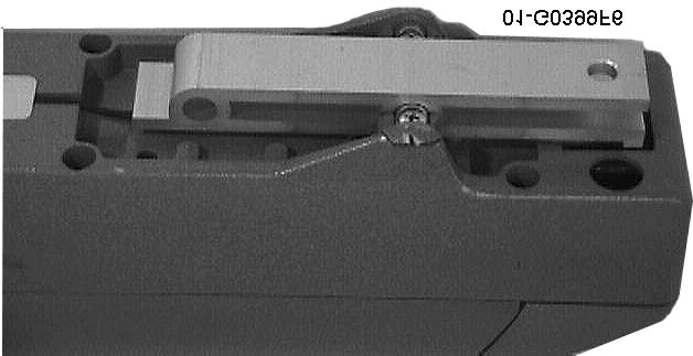
10 10 Installation CONTROL CONNECTIONS For each actuator, run (2) wires, 5 to 25 feet long of 14 gauge wire for power. Use (3) wires 16 to 20 gauge for the controls. If using (2) actuators, use motor cables of the same length and gauge to ensure the motors run at the same speed. NOTE: When actuator wiring is run to the bottom of the operator, mount using this hold (! -- see Figure 8) to prevent plate from shearing cables. 01-g03099F22 Figure 8 WARNING If operator does not stop in time, the plate may cut the cable.
11 Installation 11 Master or Single Unit Actuator #1 #3 #4 #5 #6 (red) (black) (brown) (brown) (blue) Control Box #22 #21 #9 #8 #1 Slave Unit Actuator #1 #3 #4 #5 #6 (red) (black) (brown) (brown) (blue) Control Box #19 #20 #10 #11 #1 01-G0399F17 Figure 9 INPUT/OUTPUT TERMINAL FUNCTIONS 1. Common VAC Flasher 2. Single Button VAC Courtesy Light 3. Open w/timer VAC Common 4. Pedestrian 15. Lock (-) 24 VAC for 3 Seconds 5. Safety to Stop 16. Lock (+) 24 VAC for 3 seconds 6. Safety to reverse (to open position) VDS (+) continuous 7. Stop Button VDC (-) continuous 8. Close Limit (Master or Single Unit) 19. Motor (Slave) 9. Open Limit (Master or Single Unit) 20. Motor (Slave) 10. Open Limit (Slave) 21. Motor (Master or Single) 11. Close Limit (Slave) 22. Motor (Master or Single) Table 1
12 12 Operating Instructions Operating Instructions Initial Test LIMIT SETTING AND ADJUSTMENT 1 To adjust the limits of the gate, remove end cap J by removing two K allen screws. 2 Adjust the close and open limit switches by turning the L nuts (10mm) as shown in Figure 10. Pull to Open (Typical) configuration shown. When in, Push to Open configuration, limit switches are reversed. K J Decrease Travel Increase Travel Close Limit Switch Remove End Cap Brown: Limit Switch Close Blue: Limit Switch Common L Decrease Travel Increase Travel Open Limit Switch Figure 10 Blue: Limit Switch Common Brown: Limit Switch Open 01-G0399F19
 Dip Fix 2 (condominium function): Not used for residential operations.")
13 Operating Instructions 13 PROGRAMMING Dip Fix Settings (see Figure 13) 1) Dip Fix 1 (automatic closing): 01-G0399F11 Unlatched turns on the timer to close Figure G0399F10 Latched turns off the timer to close Figure 12 NOTE: If you use Timer to Close, it is strongly recommended that you use safety equipment. 2) Dip Fix 2 (condominium function): Not used for residential operations. Leave in open position. 3) Dip Fix 3 (extension or run time): Controls the value of the max. run timer. DIP FIX OPEN = 180 sec. DIP FIX CLOSED = 90 sec. (recommended position is closed, 90 sec.) Figure 13
14 14 Operating Instructions Potentiometer Adjustments (see Figure 13) To decrease, turn potentiometer counter-clockwise. To increase, turn potentiometer clockwise. 1) Power Control Controls the electronic power limiter. Adjust it so the gate runs smoothly but can be stopped by hand. 2) Cycle Speed Controls the speed of the motor. Adjust as needed. 3) Brake Speed Controls the deceleration speed. Adjust brake for smooth operation. 4) Stop Time Works with Dip Fix 1 to control the timer to close. Min. 7-sec.; Max. 140-sec. If DIP FIX is unlatched the timer is ON. If DIP FIX is latched the timer is OFF. 5) Decel Motor 2 Adjusts the slave delay time. Min. 1-sec.; Max. 10-sec. Functional Test NOTE: Avoid setting the potentiometers to absolute minimum or maximum. ATTACH GATE Disconnect manual release (see Figure 14 and Figure 15). Swing gate by hand to ensure smooth and even operation. POWER SETTING Reconnect and lock gate manual release. Apply power and run gate. Adjust potentiometer (#1). Decrease power until gate can be stopped by hand. Increase power slightly to account for wind, snow, etc. If gate does not run smoothly, increase power further. INSTALL SAFETY EQUIPMENT Install safety equipment per the manufacturers instructions and ensure proper operation. Connect equipment as described on pages 8 and 9. DO NOT operate the gate unsupervised without testing the safety equipment. INSTALL ACCESS CONTROLS Install access control per the manufacturers instructions. Connect equipment as described on pages 9 and 9.

15 Operating Instructions 15 End User Instructions SAFETY DO NOT: Operate a gate that is not in view of the person operating the gate Allow children to play on gate Attempt to fix a gate operator yourself, call a qualified serviceman NOTE: Consult your supplier for technical support in your area. ACCESS CONTROL Make sure the user understands how to use the controls. Demonstrate them completely. Show where the power on and off is in case of an emergency. Always show how to stop and prevent entrapment. Show how to operate the manual disconnect. TROUBLESHOOTING If a problem occurs with the gate system, advise the owner of the following: Do nothing and call the installer who performed original installation. Question owner for problems per the Trouble Shooting section (page 19) for cause. Technical assistance and parts are available to qualified and approved dealers. MANUAL OPERATION The LA has a simple manual release that allows the operator to be functional when there is no electricity. See Figure 14 and Figure 15. Figure 14 1 Move lock-cover until arrow is visible. 2 Insert key and rotate 90 degrees. 3 Press the back side of the door and rotate to a click by pulling from the front side.
16 16 Operating Instructions In order for the operator to run again, lower the small door and the first operation will restore the actuator. Move in direction of arrow Pull Press Insert and rotate 90 deg. Rotate to click F23 Figure 15
17 Replacement Parts Illustrated Parts The only replacement parts available are referenced in Figure 16 and Table 2 below. Replacement Parts 17 G412HM G0399F13 BW24ST G0399F B G0399F1 Figure 16 REF. # PART # QTY. DESCRIPTION REF. # PART # QTY. DESCRIPTION Limit Switch Release Gear Release Lever Motor Pin Mounting Kit Threaded Rod B24 1 Radio Receiver Guide Cover - BW24ST 1 Actuator Support - G412HM 1 Radio Lead Screw Table 2
18 18 Replacement Parts Warranty And RGA (Returned Goods Authorization) WARRANTY LiftMaster warrants its products against defects in all workmanship and materials to the original customer for one (1) year from the date of shipment. Should a defect arise within this period, contact LiftMaster. LiftMaster will provide replacement parts or, as its option, another operator. LiftMaster cannot be responsible for damages or other cost caused by or which may result from installation, handling, non-recommended operation abuse, or modifications not authorized by LiftMaster or for damages which may arise out of use of the unit. If state laws preclude a prohibition of such damages, then the liability shall be limited to the original invoice cost. There are no other warranties of any kind, expressed or implied, including those of merchantability or fitness. Some states do not allow preclusion or limitations upon implied warranties or upon how long an implied warranty lasts or a limitation of incidental or consequential damages, so the above limitations or exclusions may not apply to you. This warranty gives you specific legal rights, and you may also have other right which vary from state to state. RGA Any part, assembly, or product sold by LiftMaster, and that is still under warranty is eligible for return for credit. For proper credit to be applied, call customer service for an RGA number. This will track your claim and ensure that proper credit is issued.
19 Service and Tech. Reference Service And Maintenance See Illustrated Parts on page 17 for part details. Service and Tech. Reference 19 Clean and lubricate jackshaft (13), support (11) and end cap (2) twice a year, more frequently if in dusty or high cycle environments. Use wheel bearing grease or similar. Also lubricate pivot points with medium weight spray lubricant. Trouble Shooting Operator will not run Operator has power but will not run Operator will open but will not close Operator sounds as if it is running but gate does not move Operator still won t run Check power source, is the breaker tripped? Make certain that 115v is getting to the control box. Is the green power LED illuminated? Disconnect power and check fuses on board. Is your control device working properly. Check batteries in transmitter. Observe the vertical row of green and red LED s, the FT.OP, FT.CL and STOP lights should not be illuminated. If any of these are on, check for obstructions to the safety devices. If any of these devices have been bypassed, check for wire breakage. Check power. Check for obstruction of safety devices. Remember, there is a three second delay before the gate operator will close. Make sure that the disconnect lever has been engaged. Call a qualified technician or LiftMaster. REQUIRED INFORMATION For best service, please have the following information: Operator model number Operator serial number Wiring diagram, diagram number and revision List of installed accessories
20 COPYRIGHT 2001 ALL RIGHTS RESERVED This document is protected by copyright and may not be copied or adapted without the prior written consent of LiftMaster. This documentation contains information proprietary to LiftMaster and such information may not be distributed without the prior written consent of LiftMaster. The software and firmware included in the LiftMaster product as they relate to this documentation are also protected by copyright and contain information proprietary to LiftMaster. FOR TECHNICAL SUPPORT Call our toll free numbers: (800) (800) Installation and service information is available six days a week. TO ORDER REPAIR PARTS Call our toll free numbers: (800) (800) Prepare to provide the following information when ordering repair parts: " Part Number " Part Name " Model Number
Installation and Maintenance Manual
 Installation and Maintenance Manual Swing Gate Operator Model HL410-21 & HL410L-21 2 Contents Contents Parts & Components 3 Specifications & Capacities 4 Safety Information 6 Installer 6 End User 7 General
HYPPOETL HYPPO DUALETL 12 VOLT DC Swing Gate Operator
 HYPPOETL HYPPO DUALETL 12 VOLT DC Swing Gate Operator Manufactured by NICE SpA INSTALLATION MANUAL 08/10 CONTENTS IMPORTANT SAFETY INSTRUCTIONS... 3 Applications...... 4 Pre-Installation Checklist... 5
APOLLO Gate Operators, Inc.
 APOLLO Gate Operators, Inc. Model 3500ETL/3600ETL Commercial Swing Gate Operator INSTALLATION MANUAL 01/08 CONTENTS IMPORTANT SAFETY INSTRUCTIONS. 3 Applications... 4 Pre-Installation Checklist... 5 Parts
Model 1550 Single Swing Gate Model 1650 Dual Swing Gate
 Gate Operators, Inc. Model 1550 Single Swing Gate Model 1650 Dual Swing Gate Swing Gate Operator CONTENTS Safety Precautions... 2 Applications... 3 Pre-Installation Checklist... 4 Parts Identification...
APOLLO Gate Operators, Inc.
 APOLLO Gate Operators, Inc. Model BA12 12 VOLT DC BARRIER ARM OPERATOR INSTALLATION MANUAL 0707 CONTENTS IMPORTANT SAFETY INSTRUCTIONS... 3 Applications... 4 Pre-Installation Checklist... 5 Operator Installation...
Gate Operators, Inc. Model 7100UL Residential & Medium Duty Commercial Slide Gate Operator INSTALLATION MANUAL
 Gate Operators, Inc. Model 7100UL Residential & Medium Duty Commercial Slide Gate Operator INSTALLATION MANUAL 10-04-00 CONTENTS Safety Precautions... 2 Applications... 3 Pre-Installation Checklist...
EXTREME R MOTOR OWNER'S MANUAL
 EXTREME R MOTOR OWNER'S MANUAL 2 HP, 3 HP & 5 HP WITH SELF-ENGAGING CHAIN HOIST FOR TECHNICAL SUPPORT PLEASE CALL 1-(855) 594-4969 3137B(0) ECN 1313 BY JM 7/9/15 OPERATOR SERIAL# PRO-FDG MOTOR OPERATORS
APOLLO Gate Operators, Inc.
 APOLLO Gate Operators, Inc. Model 7200ETL Post Mounted Residential & Heavy Duty Commercial Slide Gate Operator INSTALLATION MANUAL 04/11 CONTENTS IMPORTANT SAFETY INSTRUCTIONS... 3 Applications... 4 Pre-Installation
INSTALLATION M ANUAL
 INSTALLATION MANUAL Table of Contents UL Listings Installing the Warning Sign / Precautions Methods of Installation / Compact Installation Mounting the Secondary Entrapment / Welding Gate Arn Mounting
SAFE AND SECURE EXTREME R MOTOR OWNER'S MANUAL MODEL PRO-FDG FOR TECHNICAL SUPPORT PLEASE CALL 1-(855) OPERATOR SERIAL#
 OPERATOR SERIAL#") SAFE AND SECURE EXTREME R MOTOR OWNER'S MANUAL MODEL PRO-FDG FOR TECHNICAL SUPPORT PLEASE CALL 1-(855) 594-4969 3121B(4) ECN 1288 BY TG 2/6/15 OPERATOR SERIAL# PRO-FDG MOTOR OPERATORS MOTOR OWNER'S MANUAL
SAFE AND SECURE EXTREME R MOTOR OWNER'S MANUAL MODEL PRO-FDG FOR TECHNICAL SUPPORT PLEASE CALL 1-(855) 594-4969 3121B(4) ECN 1288 BY TG 2/6/15 OPERATOR SERIAL# PRO-FDG MOTOR OPERATORS MOTOR OWNER'S MANUAL
Instruction Manual for the. E-SL 450 Series
 Instruction Manual for the E-SL 450 Series Estate Slide Summary of Functions The Estate Slide is only to be used for vehicular Slide gates in a Class I setting. Class I: A vehicular gate opener (or system)
PowerMaster MODEL MBG. Installation Manual U L R UL 325 AND UL 991 LISTED MEDIUM DUTY BARRIER GATE OPERATOR TABLE OF CONTENTS
 PowerMaster TABLE OF CONTENTS MODEL MBG MEDIUM DUTY BARRIER GATE OPERATOR Important Safety Information...... 3 System Designer Safety Instructions.......4 Installer Safety Instructions....... 5 Installation
Model JG Industrial Gearhead Jackshaft Door Operator Safety, Installation, and Service Manual
 Model JG Industrial Gearhead Jackshaft Door Operator Safety, Installation, and Service Manual OSCO requires use of an electric edge or photoelectric control for pedestrian protection on all automatic or
INSTALLATION & OWNER'S MANUAL
 INSTALLATION & OWNER'S MANUAL THE EAGLE POWER I BATTERY BACK UP PHONE (818) 764-6690 / TOLL FREE (800) 708-8848 PRE INSTALLATION INSTRUCTIONS BEFORE PROCEEDING WITH INSTALLATION READ THIS MANUAL THOROUGHLY
Operators, Inc. Model 1550ETL Single Swing Gate Operator Model 1650ETL Dual Swing Gate Operator INSTALLATION MANUAL 04/07
 APOLLO Gate Operators, Inc. Model 1550ETL Single Swing Gate Operator Model 1650ETL Dual Swing Gate Operator INSTALLATION MANUAL 04/07 CONTENTS IMPORTANT SAFETY INSTRUCTIONS... 3 Applications... 4 Pre-Installation
TBX10A INSTALLATION/OWNER'S MANUAL 10" Sealed Enclosure with Built-in Amplifier
 TBX10A INSTALLATION/OWNER'S MANUAL 10" Sealed Enclosure with Built-in Amplifier Getting Started Thank you for purchasing the Dual TBX10A 10" ported enclosure with built-in amplifier. Although Dual has
RAMSET
 RAMSET TABLE OF CONTENTS Important Safety Requirements & Instructions...1 Responsibilities of Installers and Technicians...2 Important Safety Requirements by UL Standards...3 Classes of Vehicular Gate
FOR CLASS I, II, III, IV VEHICULAR GATE OPERATORS
 R_Ramset_Ram3000.qxd 8/19/05 4:56 PM Page 1 FOR CLASS I, II, III, IV VEHICULAR GATE OPERATORS R_Ramset_Ram3000.qxd 8/19/05 4:56 PM Page 2 www.ramsetinc.com R_Ramset_Ram3000.qxd 8/19/05 4:56 PM Page 3 TABLE
BAK1500 INSTALLATION/OWNER'S MANUAL Compact Amplified Subwoofer
 BAK1500 INSTALLATION/OWNER'S MANUAL Compact Amplified Subwoofer PREPARATION Getting Started Thank you for purchasing the Dual BAK1500 compact amplified subwoofer. Although Dual has attempted to ensure
RAMSET RAM
 www.ramsetinc.com TABLE OF CONTENTS Important Safety Requirements & Instructions...1 Responsibilities of Installers and Technicians...2 Important Safety Requirements by UL Standards...3 Classes of Vehicular
RAM TABLE OF CONTENTS
 TABLE OF CONTENTS Important Safety Requirements & Instructions...1 Responsibilities of Installers and Technicians...2 Important Safety Requirements by UL Standards...3 Classes of Vehicular Gate Operators...4
Letron Auto Gates (Australia) Pty. Ltd. User s Installation Manual
 Pty. Ltd. User s Installation Manual") Letron Auto Gates (Australia) Pty. Ltd. User s Installation Manual Sliding Gate Motor AUTOMATIC OBSTRUCT PHOTO ELECTRIC BEAM ROLLING CODE SYSTEM AUTO CLOSE DOOR SOLAR COMPATIBLE ( DC ONLY ) Model SL810
Letron Auto Gates (Australia) Pty. Ltd. User s Installation Manual Sliding Gate Motor AUTOMATIC OBSTRUCT PHOTO ELECTRIC BEAM ROLLING CODE SYSTEM AUTO CLOSE DOOR SOLAR COMPATIBLE ( DC ONLY ) Model SL810
Roller Door Operator
 INSTALLATION INSTRUCTIONS AND OWNERS MANUAL Roller Door Operator IMPORTANT PLEASE READ THESE INSTRUCTIONS CAREFULLY PRIOR TO COMMENCING THE INSTALLATION OF THE OPERATOR UNIT CAUTION This Automatic Opener
CMD-4000 SERIES REV. A 4+ FUNCTION REMOTE CONTROL DOOR LATCH OPENER SYSTEM INTRODUCTION
 CMD-4000 SERIES REV. A 4+ FUNCTION REMOTE CONTROL DOOR LATCH OPENER SYSTEM INTRODUCTION Thank you for purchasing the CMD-4000 series Remote Control Door Latch Opener System from Dakota Digital, Inc. This,
FOR CLASS I, II, III, IV VEHICULAR GATE OPERATORS
 Ramset_Man300.qxd 4/18/05 1:06 PM Page 1 FOR CLASS I, II, III, IV VEHICULAR GATE OPERATORS Ramset_Man300.qxd 4/18/05 1:06 PM Page 2 www.ramsetinc.com Ramset_Man300.qxd 4/18/05 1:06 PM Page 3 TABLE OF CONTENTS
MODEL JH JACKSHAFT INDUSTRIAL DOOR OPERATOR INSTALLATION MANUAL. OPERATOR SPECIALTY COMPANY, INC. P.O. Box 128 Casnovia, MI 49318
 MODEL JH JACKSHAFT INDUSTRIAL DOOR OPERATOR INSTALLATION MANUAL OPERATOR SPECIALTY COMPANY, INC. P.O. Box 128 Casnovia, MI 49318 OSCO requires the use of a reversing edge or photoelectric control for pedestrian
PSX-240 Enclosed Autotransformer Installation Manual
 PSX-240 Enclosed Autotransformer Installation Manual IMPORTANT SAFETY INSTRUCTIONS SAVE THESE INSTRUCTIONS! This manual contains important instructions for the OutBack PSX-240 Autotransformer. All of the
115 VAC Control Boxes for
 CLASS 582 HP OPEN CLOSE Wiring / Owner s Manual Use this manual for circuit board 02-010 Revision A or higher. 115 VAC Control Boxes for 6002, 600, 600 and 600 gate operators 02-065-E-5-12 CFORMS TO ANSI/UL-25
12V DC MOTORISED OPENER FOR SWING GATES Section Table of Contents Page
 12V DC MOTORISED OPENER FOR SWING GATES Section Table of Contents Page 1 Introduction 2 2 Warnings 4 3 Technical Specifications 5 4 Positioning 6 5 Wiring Diagram 7 6 Standard Installation Kit 8 7 Installation
MODEL D-SBG Single Arm Barrier Gate Operator
 INSTALLATION AND OWNER S MANUAL MODEL D-SBG Single Arm Barrier Gate Operator UL 325 and UL 991 Listed WITH NITRO BOARD (SEE SUPPLEMENTAL MANUAL) Serial #: Date Installed: Your Dealer: READ THIS MANUAL
Installation & Operation Manual PWS1000R Rack Mount Power Supply
 Installation & Operation Manual PWS1000R Rack Mount Power Supply 8128 River Way, Delta B.C. V4G 1K5 Canada T. 604.946.9981 F. 604.946.9983 TF. 1.800.668.3884 (US/CANADA) www.analyticsystems.com Copyright
CIVACON GROUND VERIFICATION RACK MONITOR SYSTEM and ASSOCIATED EQUIPMENT
 GROUND VERIFICATION RACK MONITOR SYSTEM and ASSOCIATED EQUIPMENT INSTALLATION AND WIRING INSTRUCTIONS MANUAL 8030 MANUAL PART NUMBER JANUARY 2011. 4304 MATTOX RD. KANSAS CITY, MO 64150 TABLE OF CONTENTS
WF-5100 Series True Sine Wave Inverters
 Operator s Manual WF-5100 Series True Sine Wave Inverters WF-9900 Series WF-5118 WF-5120 ( The Inverter model number is located on the label on top of the enclosure) Distributed in the U.S.A. and Canada
TALCO FIRE SYSTEMS. LSF Start-Up Instructions. 1) IMPORTANT: Inspect the unit for damage. Report any damage to the freight carrier immediately.
 IMPORTANT: Inspect the unit for damage. Report any damage to the freight carrier immediately.") LSF Start-Up Instructions 1) IMPORTANT: Inspect the unit for damage. Report any damage to the freight carrier immediately. 2) PRE-START-UP: Be sure there is water in the pump. Bleed air at all high points
LSF Start-Up Instructions 1) IMPORTANT: Inspect the unit for damage. Report any damage to the freight carrier immediately. 2) PRE-START-UP: Be sure there is water in the pump. Bleed air at all high points
Installation and Maintenance Instructions
 Installation and Maintenance Instructions Medium & Heavy Duty Swing Gate Operators Models: SW470 SW490 2 Contents Contents General Information 4 Parts Supplied 4 Model Classifications 4 Specifications
Heavy Duty Commercial Linear Gate Operator
 MAX SUPER ARM 2300 Heavy Duty Commercial Linear Gate Operator Moves heavy gates up to 20 High traffic high wind Self-locking, Mag Lock unnecessary Overload clutch release on 3 ton impact MAX AC control
MODEL MSW Medium Duty Swing Gate Operator
 INSTALLATION AND OWNER S MANUAL MODEL MSW Medium Duty Swing Gate Operator UL 325 and UL 991 Listed 22-1/4 16-1/2 19-1/2 16 20'' LENGTH X 14-3/4'' WIDTH 2 O.D. PIPE (BY OTHERS) Serial #: Date Installed:
FOR CLASS I VEHICULAR GATE OPERATORS
 FOR CLASS I VEHICULAR GATE OPERATORS www.ramsetinc.com TABLE OF CONTENTS Important Safety Requirements & Instructions.... 1 Responsibilities of Installers and Technicians. 2 Important Safety Requirements
Plus SABRE LIGHTBARS
 INSTALLATION AND INSTRUCTION MANUAL Plus SABRE LIGHTBARS Models 5364LED, 5462LED, 5464LED and 5564LED PLIT445 REV. D 2/2/18 Keep any radio frequency sensitive equipment at least 20 from the bar and power
US208S Scooter / Power Chair Carrier Lift N Go 117 Mini Electric Lift Electric Tote & 130 Swing Away Installation Guide & Owners Manual
 7325 Douglas Rd. Lambertville, MI 48144 Phone: 1-800-541-3213 Fax: (734) 568-6705 www.wheelchaircarrier.com E-mail: admin@wheelchaircarrier.com US208S Scooter / Power Chair Carrier - 210 Lift N Go 117
Installation/Owner s Manual Series 6500
 Installation/Owner s Manual Series 00 Use this manual for circuit board 0-00 Revision E or higher. EXTERNAL ENTRAPMENT PROTECTI MUST be installed or the gate operator WILL NOT function. Vehicular Swing
CBC-802 Plug-In Clutch/Brake Control with Solid State Switching
 DIST. AUTORIZADO Plug-In Clutch/Brake Control with Solid State Switching P-29-5 19-0409 Service & Installation Instructions An Altra Industrial Motion Company DIST. AUTORIZADO Brake (Red) and clutch (Green)
Installation and Set Up Instructions
 Model FG 5-7 / SW 5-7 / DSW 5-7 Swing Gate Motor Kit Solar powered and 12V Low Voltage Installation and Set Up Instructions Unit 27 / 49 Corporate Boulevard Bayswater Vic 3153 Phone 1800 111 930 Email
PD404-AN V analog control 4 Channel x 500 W Dimmer & Switch Packs ANALOG 0-10 V. Serial Number
 0-10V analog control 4 Channel x 500 W Dimmer & Switch Packs ANALOG 0-10 V 4 circuit Analog 1-10V 4 x 4 A. Dimmer pack Serial Number Dimmers Indicators Digital Lighting Systems,Inc Info@digitallighting.com
Installation and Set Up Instructions
 SL 2000 DC2 SLIDING GATE MOTOR KIT Solar Powered and 12V Low Voltage Installation and Set Up Instructions Unit 27 / 49 Corporate Boulevard Bayswater Vic 3153 Phone 1800 111 930 Email info@gforceautogates.com.au
COOKSON OWNER'S MANUAL
 COOKSON OWNER'S MANUAL FDO-A10 INDUSTRIAL DUTY FIRE DOOR OPERATOR R L I S T E D 3040233 US CONTROL PANEL SERIAL# OPERATOR SERIAL# 9001.DWG ECN 0959 REV 4 SPECIFICATIONS MOTOR TYPE:...INTERMITTENT HORSEPOWER:...1/8
# & XFI Chrysler Big Block ( A Series)/ Hemi/440RB Series Dual Sync Distributor
/ Hemi/440RB Series Dual Sync Distributor") 1 INSTRUCTIONS #305012 & 305013 XFI Chrysler Big Block (383-400A Series)/ Hemi/440RB Series Dual Sync Distributor Thank you for choosing products; we are proud to be your manufacturer of choice. Please
1 INSTRUCTIONS #305012 & 305013 XFI Chrysler Big Block (383-400A Series)/ Hemi/440RB Series Dual Sync Distributor Thank you for choosing products; we are proud to be your manufacturer of choice. Please
ADDENDUM MODEL S3 OPERATORS Models: SL/540/570/580/590 & SW420/470/490
 ADDENDUM MODEL S3 OPERATORS Models: SL/540/570/580/590 & SW420/470/490 This addendum is to be used in conjunction with the owner s manual included with this operator. Refer to this addendum for all programming
HAZARDOUS (NEMA 7/9) INDUSTRIAL DUTY COMMERCIAL DOOR OPERATOR 2 YEAR WARRANTY. Serial # Box. Installation Date. Wiring Type
 INDUSTRIAL DUTY COMMERCIAL DOOR OPERATOR 2 YEAR WARRANTY. Serial # Box. Installation Date. Wiring Type") O W N E R S M A N U A L HAZARDOUS (NEMA 7/9) INDUSTRIAL DUTY COMMERCIAL DOOR OPERATOR 2 YEAR WARRANTY Serial # Box Installation Date Wiring Type TABLE OF CONTENTS SPECIFICATIONS Operator Dimensions.................................
O W N E R S M A N U A L HAZARDOUS (NEMA 7/9) INDUSTRIAL DUTY COMMERCIAL DOOR OPERATOR 2 YEAR WARRANTY Serial # Box Installation Date Wiring Type TABLE OF CONTENTS SPECIFICATIONS Operator Dimensions.................................
Model H/HB Heavy-Duty Industrial Drawbar Door Operator Safety, Installation and Service Manual
 Model H/HB Heavy-Duty Industrial Drawbar Door Operator Safety, Installation and Service Manual OSCO requires use of an electric edge or photoelectric control for pedestrian protection on all automatic
INSTRUCTIONS FOR OUTDOOR WALL LANTERN, MODEL LPT-1107
 INSTRUCTIONS FOR OUTDOOR WALL LANTERN, MODEL LPT-1107 Page 1 Thank you for purchasing this Langport Lighting outdoor wall lantern. This product has been manufactured with the highest standards of safety
Gate & Door Controller with LCD and Intelligent Technology
 2nd Edition Gate & Door Controller with LCD and Intelligent Technology 24Sv1 and 12Sv1 Motor Controllers Setup and Technical information for single motor controller for gates & doors Includes latest Intelligent
Installation/Owner s Manual Series 6500
 Installation/Owner s Manual Series 00 Use this manual for circuit board 0-08 Revision A or higher. Vehicular Swing Gate Operator Entrapment Protection must be provided for the gate system where the risk
Installing the gate post bracket with the cardboard arm template
 ......... Installing the gate post bracket with the cardboard arm template... Installing gate posts brackets and arms for Push-to-Open or Pull-to-Open gates... Connection of Power Source 240Vac or Solar...
Installing the gate post bracket with the cardboard arm template
 ......... Installing the gate post bracket with the cardboard arm template... Installing gate posts brackets and arms for Push-to-Open or Pull-to-Open gates... Connection of Power Source 240Vac or Solar...
WF-5110R True Sine Wave Inverter
 Operator s Manual WF-5110R True Sine Wave Inverter WF-9900 Series WF-5110R ( The Inverter model number is located on the label on top of the enclosure) Distributed in the U.S.A. and Canada by ARTERRA DISTRIBUTION
Installation Instructions
 Please read all instructions before installing CD-250 Multi-way Dimming Wall Switch Vacancy Sensor Lens Air Gap Isolation Switch Lighted Switch ON/OFF/DIM button SPECIFICATIONS Voltage...120VAC, 60Hz Load
EC MACHINE DIRECTIVE COMPLIANCE DECLARATION
 770 EC MACHINE DIRECTIVE COMPLIANCE DECLARATION (DIRECTIVE 89/392 EEC, APPENDIX II, PART B) Manufacturer: FAAC S.p.A. Address: Via Benini, 1 40069 - Zola Predosa BOLOGNA - ITALY Hereby declares that: the
CBC-802 Plug-In Clutch/Brake Control with Solid State Switching
 CBC-02 Plug-In Clutch/Brake Control with Solid State Switching P-2104-WE 19-054 Service & Installation Instructions An Altra Industrial Motion Company Brake (Red) and clutch (Green) indicator lights When
115 VAC Control Boxes for
 CLASS MODEL SERIAL 58 HP CLOSE Wiring / Owner s Manual Use this manual for circuit board 0-010 Revision A or higher. EXTERNAL ENTRAPMENT PROTECTI MUST be installed or the gate operator WILL NOT function.
CRD610 Automatic Fitting Inserter
 CRD610 Automatic Fitting Inserter OPERATIONS MANUAL VERSION 1.2 LAST EDITED 12.12.2018 cleanroomdevices.com 1 Table of Contents Title Page. 1 Table of Contents...2 1.0 General Product & Safety Information....3
Hunter Automatics HA-8. Installation Manual
 Hunter Automatics HA-8 Installation Manual WARNING TO REDUCE RISK OF INJURY 1. READ AND FOLLOW ALL INSTALLATION INSTRUCTIONS CAREFULLY. FAILURE TO DO SO MAY RESULT IN PERSONAL INJURY OR PROPERTY DAMAGE
MODEL D-WBG Wishbone Arm Barrier Gate Operator
 INSTALLATION AND OWNER S MANUAL MODEL D-WBG Wishbone Arm Barrier Gate Operator UL 325 and UL 991 Listed WITH NITRO BOARD (SEE SUPPLEMENTAL MANUAL) Serial #: Date Installed: Your Dealer: READ THIS MANUAL
12 STATION MANUAL CONTROLLER INSTALLATION AND OPERATING GUIDE MODEL HRM-12
 Ed Hydro Rain. 12 STATION MANUAL CONTROLLER INSTALLATION AND OPERATING GUIDE MODEL HRM-12 The HRM-12 is a 12 station controller that can be set to water from twenty-four times a day to once every two weeks.
INSTALLATION & OPERATION MANUAL
 INSTALLATION & OPERATION MANUAL VTC180 DC/DC Converter An ISO9001 and AS9100 Registered Company Battery Chargers Inverters Power Supplies Voltage Converters 8128 River Way, Delta B.C. V4G 1K5 Canada T.
SL-1000 Stairlift OWNER S MANUAL
 SL-1000 Stairlift OWNER S MANUAL (To Be Retained by Owner After Installation by Authorized Savaria Dealer) Part No. 000729 03-m12-2013 2 IMPORTANT Ensure that only an authorized Savaria Dealer installs
GC-1. Roof and Gutter De-Icing Control Installation and Operating Instructions FOR EXTERIOR INSTALLATION ONLY
 GC-1 Roof and Gutter De-Icing Control Installation and Operating Instructions FOR EXTERIOR INSTALLATION ONLY GENERAL INFORMATION The GC-1 heating cable controller has been designed and manufactured for
Table of Contents. General Safety Preparation for Installation Parts List Optional Accessories Part List... 5
 REV 12a Table of Contents General Safety....... 2 Preparation for Installation....... 3 Parts List....... 4 Optional Accessories Part List...... 5 Technical Specifications & Feature...... 5 Installation
Installation and Set Up Instructions
 SL SLIDING GATE MOTOR KIT Solar Powered and 12V Low Voltage Installation and Set Up Instructions Unit 27 / 49 Corporate Boulevard Bayswater Vic 3153 Phone 1800 111 930 Email info@gforceautogates.com.au
CRD600 Automatic Fitting Inserter
 CRD600 Automatic Fitting Inserter OPERATIONS MANUAL VERSION 2.3 LAST EDITED 12.07.2018 cleanroomdevices.com 1 Table of Contents Title Page.. 1 Table of Contents. 2 1.0 General Product & Safety Information...3
OWNER S MANUAL MODEL NO. MEDIUM DUTY JACK SHAFT OPERATOR MDJ, MDJH, MDJB, MDJBH READ AND FOLLOW ALL INSTALLATION INSTRUCTIONS SAVE THESE INSTRUCTIONS
 OWNER S MANUAL MEDIUM DUTY JACK SHAFT OPERATOR MODEL NO. NOT FOR RESIDENTIAL USE READ AND FOLLOW ALL INSTALLATION INSTRUCTIONS SAVE THESE INSTRUCTIONS This unit is intended for limited duty applications
HYDRAULIC LEVELING SYSTEMS OPERATIONS MANUAL (For systems with touch pad part number , , , , or no number at all)
") HYDRAULIC LEVELING SYSTEMS OPERATIONS MANUAL (For systems with touch pad part number 500089, 500105, 500210, 500456, 500535 or no number at all) Visit us on the web at www.powergearus.com 82-L0040-01 Rev.
HYDRAULIC LEVELING SYSTEMS OPERATIONS MANUAL (For systems with touch pad part number 500089, 500105, 500210, 500456, 500535 or no number at all) Visit us on the web at www.powergearus.com 82-L0040-01 Rev.
US208S Scooter Carrier - US208P Power Chair Carrier 210 Lift N Go 130 Swing Away Installation Guide & Owners Manual
 7325 Douglas Rd. Lambertville, MI 48144 Phone: 1-800-541-3213 Fax: (734) 568-6705 www.wheelchaircarrier.com E-mail: admin@wheelchaircarrier.com US208S Scooter Carrier - US208P Power Chair Carrier 210 Lift
Saimatic Aster Gate Operator, Automation System Manual. 110V or 220V
 Saimatic Aster Gate Operator, Automation System Manual 110V or 220V 1 WARNINGS AND PRECAUTIONS Read the instructions carefully before installing the gate automation system. Keep these instructions for
VTC610 Series Voltage Converter. Installation & Operation Manual
 VTC610 Series Voltage Converter Installation & Operation Manual IMPORTANT SAFETY INSTRUCTIONS 1) SAVE THESE INSTRUCTIONS This manual contains important safety and operating instructions for this voltage
OWNER S MANUAL AND INSTALLATION INSTRUCTIONS
 EmerGen Switch Manual Transfer Switch OWNER S MANUAL AND INSTALLATION INSTRUCTIONS For A Series Models 6-5001, 6-7501, 10-7501, 10-12K1 PLEASE READ THIS MANUAL IN ITS ENTIRETY BEFORE INSTALLING AND/OR
EC MACHINE DIRECTIVE COMPLIANCE DECLARATION
 EC MACHINE DIRECTIVE COMPLIANCE DECLARATION (DIRECTIVE 89/392 EEC, APPENDIX II, PART B) Manufacturer: FAAC S.p.A. Address: Via Benini, 1 40069 - Zola Predosa BOLOGNA - ITALY Hereby declares that: the 770
CMD-4000 SERIES REV. A 4+ FUNCTION REMOTE CONTROL DOOR LATCH OPENER SYSTEM INTRODUCTION
 CMD-4000 SERIES REV. A 4+ FUNCTION REMOTE CONTROL DOOR LATCH OPENER SYSTEM INTRODUCTION Thank you for purchasing the CMD-4000 series Remote Control Door Latch Opener System from Dakota Digital, Inc. This,
PowerMaster Model SG
 PowerMaster Model INSTALLATION MANUAL CAREFULLY READ THIS ENTIRE MANUAL FIRST BEFORE PROCEEDING! LEAVE THIS MANUAL WITH END USER FOR FUTURE REFERENCE AFTER INSTALLATION IS COMPLETE (LAST PAGE SHOULD BE
Irrigation Components International, Inc.
 1500 Irrigation Components International, Inc. P.O. Box 945 Daphne, AL 36526 USA Tel: 251.626.5470 Fax: 251.447.0190 Email: icii@irricomp.com Visit us on the web: www.irricomp.com 1500 TABLE OF CONTENTS
CLASSIC II Portable Braking System
 39495 CLASSIC II Portable Braking System Inventor and Leader in Portable Technology! INSTRUCTIONS NEED HELP? CALL - 1-800-470-2287 (MONDAY - FRIDAY 8AM - 5PM CST) WARNING Read all instructions before installing
Installation & Operation Manual. Electrak 10 Series / Electromechanical Linear Actuator
 www..com Installation & Operation Manual Electrak 10 Series / Electromechanical Linear Actuator INTRODUCTION Thomson has many years of experience designing and manufacturing linear actuators for a wide
MD10. Engine Controller. Installation and User Manual for the MD10 Engine Controller. Full Version
 MD10 Engine Controller Installation and User Manual for the MD10 Engine Controller. Full Version File: MartinMD10rev1.4.doc May 16, 2002 2 READ MANUAL BEFORE INSTALLING UNIT Receipt of shipment and warranty
INSTALLATION INSTRUCTIONS
 0711016 Page 1 INSTALLATION INSTRUCTIONS ELECTRONIC DEADBOLT WITH KEYPAD latch 2-3/8 Your latch is now set 2-3/8 (60mm) backset latch 2-3/4 2-3/4" (70mm) 2-3/8" (60mm) Cylindrical cover Extension plate
Owner s Manual. Models 6050 and 6100 Vehicular Swing Gate Operators
 Owner s Manual Models 6050 and 6100 Vehicular Swing Gate Operators DoorKing, Inc. 120 Glasgow Avenue Inglewood, California 90301 U.S.A. Phone: 310-645-0023 Fax: 310-641-1586 www.doorking.com P/N 6050-065
12 Series Linear Electric Actuator Installation, Operation & Maintenance Manual
 12 Series Linear Electric Actuator Installation, Operation & Maintenance Manual TELEPHONE: +1-859-727-7890 TOLL FREE: +1-800-662-9424 FAX: +1-859-727-4070 E-MAIL: DVOGES@INDELAC.COM MROBINSON@INDELAC.COM
FOR New Electric Kit and Remote Control Installation
 Installation Manual COMMAND-10 REMOTE AND COMMAND STATION FOR New Electric Kit and Remote Control Installation Use these in place of the rocker switch and solenoid section of instructions in your roll
Vehicular Swing Gate Operator. Nice. Titan 912L. The Titan 912L Gate Operator is intended for use with vehicular swing
 Vehicular Swing Gate Operator Nice Gate Operators Titan 912L The Titan 912L Gate Operator is intended for use with vehicular swing gates. The Titan 912L Gate Operator can be used in Class I, Class II and
Installation/Owner s Manual
 CLASS MODEL SERIAL HP 53382 Read owner s manual and safety instructions. Installation/Owner s Manual Use this manual for circuit board 4502-010 Revision AA or higher. EXTERNAL ENTRAPMENT PROTECTI MUST
BC-9000 OPERATIONS MANUAL BATTERY CHARGER COFKO ELECTRONICS LLC COPYRIGHT 2014 P/N
 BC-9000 BATTERY CHARGER OPERATIONS MANUAL COFKO ELECTRONICS LLC COPYRIGHT 2014 P/N 4169-20 UNPACKING As you unpack your new BC-9000 battery charger, inspect the BC-9000 for signs of shipping damage. If
CLEAN ROOM DEVICES, LLC "WHERE TUBING AND FITTINGS COME TOGETHER"
 CLEAN ROOM DEVICES, LLC "WHERE TUBING AND FITTINGS COME TOGETHER" CRD600 Automatic Fitting Inserter OPERATIONS MANUAL VERSION 2.1 LAST EDITED 7.25.14 DOCUMENT NUMBER 001 cleanroomdevices.com 1 Table of
i n s t r u c t i o n m a n u a l
 i n s t r u c t i o n m a n u a l 8006 Six-Station AC Timer Residential/Light Commercial Independent Program Irrigation Controllers Installation, Programming and Operating Instructions Features Operates
Two Channel Remote Shutdown Device
 Installation & Operation Standard Features: Two Channel Remote Shutdown Device I. Introduction Latched shutdown for increased safety Powerful transmitter with 300 feet range Waterproof sealed transmitter
Nice Apollo Swing Gate Opener Model 1500
 Nice Apollo Swing Gate Opener Model 500 Model 600 Vehicular Swing Gate Opener Revision.0.0.0_-04 TABLE OF CONTENTS EXTREMELY IMPORTANT TECHNICAL SPECIFICATIONS - OVERVIEW - GATE INFORMATION. - ASTM F00.
INSTALLATION & OPERATION MANUAL
 INSTALLATION & OPERATION MANUAL VTC125d-6-12 Voltage Converter An ISO9001 and AS9100 Registered Company Battery Chargers Inverters Power Supplies Voltage Converters 8128 River Way, Delta B.C. V4G 1K5 Canada
MODEL WBG WISHBONE BARRIER GATE OPERATOR
 TABLE OF CONTENTS MODEL WBG WISHBONE BARRIER GATE OPERATOR Important Safety Information.....3 System Designer Safety Instructions.......4 Installer Safety Instructions........ 5 End User Safety Warnings...-
Owner s Manual and Warranty Information
 RAVE STAIR LIFT Owner s Manual and Warranty Information IMPORTANT! YOU MUST READ AND UNDERSTAND THIS ENTIRE MANUAL BE READ AND UNDERSTOOD BEFORE ATTEMPTING TO OPERATE THIS LIFT. IF THERE IS ANYTHING IN
INSTALLATION INSTRUCTIONS AND OPERATION MANUAL
 INSTALLATION INSTRUCTIONS AND OPERATION MANUAL Commercial and Industrial Fire Door Operator Logic Control Restricted Duty Fire Door Operators IMPORTANT INSTALLATION INSTRUCTIONS WARNING To reduce the risk
Installation & Operation Manual. Electrak 100 Series / Electromechanical Linear Actuator
 www..c Installation & Operation Manual Electrak 100 Series / Electromechanical Linear Actuator Thomson has many years of experience designing and manufacturing linear actuators for a wide variety of applications
The POWER In PRESENTATION PRODUCTS
 Instruction Book For G-200-LC Standard Model (110 /120Vac) The POWER In PRESENTATION PRODUCTS DA-LITE SCREEN COMPANY, INC. 3100 North Detroit Street Post Office Box 137 Warsaw, Indiana 46581-0137 Phone: