TABLE OF CONTENTS. 1 How to Use Control gauge and Rocker Switch Mounting Hardware... 3
|
|
|
- Brianna Griffin
- 5 years ago
- Views:
Transcription
1 1
2 TABLE OF CONTENTS 1 How to Use Control gauge and Rocker Switch Mounting Hardware Trailering with the SWITCHBLADE Maintaining your SWITCHBLADE INSTALLATION Procedures Disclaimer Parts and Tool List Lifting Arm Assembly Electrical Assembly Wiring Diagram Installation TESTS and Troubleshooting... 8 Disclaimer USE THIS DEVICE RESPONSIBLY. The SWITCHBLADE is designed to increase the size of the wake. PLEASE REMEMEBER you may be held responsible for any damage your wake causes to other people s property. Before you take the first test ride, you should read and familiarize yourself with everything in this document. It is strongly recommended that all drivers experience operating the SWITCHBLADE before attempting to pull boarders. o Learn the SWITCHBLADE s effect on the boat s wake. o Learn the SWITCHBLADE s effect on the boat s handling at all speeds. o Learn the SWITCHBLADE s effect on slow speed docking situations. 2


3 1 How to Use 1.1 Control Gauge and Rocker Switch UP/DN Press Up to decrease the size of the wake. Press DOWN to increase the size of the wake. 1.2 Mounting Hardware Mounting Plate Mounts the SWITCHBLADE to the boat and provides the hinge for the rudder to pivot up and down AND swivel right to left. Pivot Remove the pivot bolts to remove the rudder for long trailering situations. This will relieve undo stress on the mount and transom. Note: The bottom bolt is smaller and made of brass. It acts as a shear pin in the event that something is hit below the water. Rudder This is the vertical part of the SWITCHBLADE. It swivels freely to port and starboard as it follows the boat s rudder, enhancing the steering capabilities of your boat. It also pivots up and down to adjust the size of the wake. Blade The Blade is the horizontal part of the SWITCHBLADE that actually forms the shape of the wake. Electric Rams The electric rams actuate to move the rudder and fin for adjustments of the wake. 3
4 1.3 Trailering with the SWITCHBLADE DO NOT TRAILER WITH THE BLADE ATTACHED!!! If you choose to, be especially cautious when trailering with the SWITCHBLADE rudder in place. The SWITCHBLADE is designed to be HIGHER than the boats original running gear (rudder and propeller). Therefore, the SWITCHBLADE should clear any obstacle the boat clears. Please remember that it is mounted aft and there is a chance of it hitting ground. It is recommended that the SWITCHBLADE s rudder be removed from the boat if you are trailering your boat. This is to relieve undue stress on your transom and remove the possibility of hitting anything with the SWITCHBLADE s rudder. Remove the rudder by taking out the two bolts on the rudder swivel AND removing the swivel pin from the bushings. The rudder will slide AFT off of the pin. Place the pin back on the rudder and store them in a safe place. When replacing the rudder, note that the bottom bolt is smaller so that it might shear first in the case of hitting something. Replace the pin with the small hole to the bottom, insert the top bolt first, then the bottom (smaller) bolt. While you are there, inspect the part for any signs of wear. 1.4 Maintaining your SWITCHBLADE The SWITCHBLADE exterior parts are made of stainless steel and will hold up to the rigors of a water environment, but it still needs to be maintained. Custom Stainless & Aluminum Products, Inc. suggests these regular maintenance procedures. 1) Visually inspect all parts for smooth operation before each session. 2) Always rinse the exterior off with fresh, clean water after use in salt water. 3) Check all bolts for tightness once per month. 4) Make sure your rams FREE WHEEL when at minimum and maximum travel. Test this by running the rams all the way in. Listen for both of the rams to keep running WITHOUT any groan. Do the same test with the rams all the way out. 2 INSTALLATION Procedures 2.1 Disclaimer Installation of the SWITCHBLADE should be performed by a trained mechanic. Installation of this device can be achieved with basic tools and understanding of fiberglass and mechanical principles. However, Custom Stainless & Aluminum Products, Inc. cannot accept liability if installation is attempted by anyone other than an authorized dealer. Custom Stainless & Aluminum Products, Inc. is not responsible for damage incurred to the boat from improper installation of this part. 4
 1) Drill 2) 1/2 inch drill bit 3) 3/8 inch drill bit 4) 3/4 wrench 5) 5/16 socket and appropriate ratchet 6) Wire strippers 7) Wire cutters 8) Wire crimpers 9) Tie")
5 2.1 Parts and Tool List Parts List (provided) 1) Lifting Arm Assembly with rams and wire leads 2) Backing Plate 3) Blade 4) Control Module 5) Wire Harness 6) Gauge 7) Rocker Switch 8) Assorted hardware Tool List (not provided) 1) Drill 2) 1/2 inch drill bit 3) 3/8 inch drill bit 4) 3/4 wrench 5) 5/16 socket and appropriate ratchet 6) Wire strippers 7) Wire cutters 8) Wire crimpers 9) Tie wraps 10)Countersink 11)Masking tape 12)Silicone sealant 13)30 amp Fuse and holder 14)Antiseize paste 2.3 Lifting Arm Assembly Setup The transom lifting arm assembly will be installed first. The area need is approximately 10 inches wide by 6 inches high DIRECTLY ABOVE the keel or centerline of the boat. Note: Outside If this area has a trim tab installed; it will need to be removed. Inside Remove the gas tank, exhaust manifold and anything else on the centerline of the boat near the transom. Holes will be drilled through the transom so access is needed to this area. 5
6 Important: It is vital to the function of the SWITCHBLADE that the transom is 90 in the vertical plane to the plane of the keel. If your transom is anything other than this, contact your SWITCHBLADE representative before drilling any holes. A custom shim may be needed for proper mounting Installation Prepare the gelcoat by placing some MASKING TAPE on the area where the holes will be drilled. The masking tape will help keep the gelcoat from chipping Place the backing plate directly above the drain plug and trace the whole pattern onto the transom. The CENTERLINE of the pattern should be measured 18 to 20 inches UP from the bottom of your rudder or the bottom of the template should be 1-2 inches above the bottom of the keel. Note: It is extremely important to find the exact centerline of the hull. DO NOT measure from exhaust ports, platform brackets, speedometer pickups, etc, as these MAYNOT be symmetrical. The best place to measure is from the chine or bottom outside corner of the boat Once marked, proceed drilling the 4 major holes (1/2 ), then the 2 minor holes (3/8 ). Tip: Start each hole with a small pilot hole, such as 1/8. After these holes are drilled, ensure that the holes did not puncture anything on the interior of the boat. Then use a countersink to bevel the edges. This will reduce the possibility of any crazing of the gelcoat later on. You should use progressively bigger drills until you ve reached the desired size, this will also reduce the chance of crazing or cracking the gelcoat Next, install the lifting arm by bolting thru the mounting plate, thru the transom and thru the backing plate. Seal each hole with a silicone sealant. Thread the nuts on the inside of the boat and torque down appropriately. Note: Use ANTISEIZE on all stainless steel bolts. Stainless steel nuts HEAT up when turned on their bolt. They WILL seize (weld themselves to the bolt) if you work them too fast or don t put an anti-seize paste on them. If you use a ratchet, MOVE SLOWLY when threading the nut in place Now that the lifting arm is installed you will need to slide the actuator wires thru the 3/8 holes in the transom. Seal with silicone, then fish the ram wires up to the dash area. Use wire ties to secure these wires in place as you move forward, making sure they do not come in contact with moving engine parts or exhaust system components Install the Blade Assembly to the Lifting Arm by inserting the pivot through the plastic bushings. Insert the top hole of the blade into the top slot of the pivot. Insert the STAINLESS STEEL bolt and nut. Now insert the bottom hole of the blade into the bottom slot of the pivot. Insert the BRASS bolt and nut. Tighten 6

 Secure the gauge and switch to the dash. 2.4.")

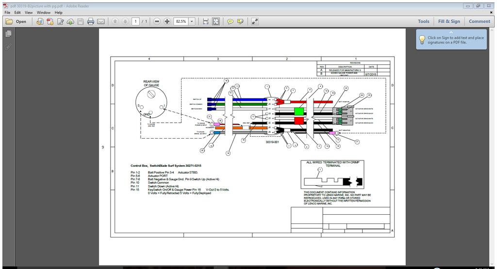
7 both bolts Ensure that all other bolts in the assembly are tight. 2.4 Electrical Assembly Important: Before performing any work with electronics, remove the negative (-) lead from the battery Find a place to mount the Gauge and Rocker Switch. Ensure that the appropriate controller leads will reach the battery, dash and actuator leads Once at the dash, decide if you will use an empty hole in the existing dash for your gauge such as a clock. You will need a location for the rocker switch next to the gauge. If there isn t an empty hole, you can make a pattern of the two. Use a drill or Dremmel tool to remove material for the controls. Fish the control wires through the dash and connect appropriately. (refer to the wiring diagram) Secure the gauge and switch to the dash Proceed to install the power wires leading from the Control box. Two wires will be connected directly to the battery, one positive (+, red) and one negative (-, black). Insert a 30 amp resettable breaker in the positive line Plug the lead wires from the actuators into the Control Module. 2.5 Wiring Diagram ***********************************REFER TO PAGE 9*************************************** 7

8 2.6 Installation TESTS and Troubleshooting Dry Testing Press UP to raise the unit and DOWN to lower the unit. The blade should travel up and down appropriately. If this doesn t happen, check your wiring. Watch the gauge to make sure it is moving in the right direction. If this doesn t happen, check your wiring Wet Testing Press UP to decrease the wake and DOWN to increase the wake. The wake should increase and decrease appropriately. If this doesn t happen, check your wiring. Watch the gauge to make sure it is moving in the right direction. If this doesn t happen, check your wiring Check bilge for water intrusion Dry Testing Ensure all bolts are tight and there is no leaking. Custom Stainless & Aluminum Products, Inc Littleton Road North Fort Myers, FL Sales and Tech questions please call or For performance and set up inquires please contact our professional advisor (rider), JamesZ, at (415)
9 9
Owner s Manual And Guide To Installation
 Owner s Manual And Guide To Installation < # > TABLE OF CONTENTS 1 How to Use...3 1.1 Control Keypad...3 1.2 Mounting Hardware...4 1.3 Auto Launch Details...5 1.4 Trailering with the SWITCHBLADE...6 1.5
INSTALLATION MANUAL. Power-Pole Blade Edition Shallow Water Anchor. Installation Instructions
 INSTALLATION MANUAL Power-Pole Blade Edition Shallow Water Anchor Installation Instructions CAUTION: Read this instruction manual carefully. Become familiar with the controls and know how to operate the
Spectra C3 Light Bar Installation Instructions
 Light Bar Hardware Tools Required Universal Clamp Inserts 1.9, 2 3/8 - OD 5 Amp Fuse 1.25 Hole Saw Philips Screw Driver 7/64 Drill Bit Fish Tape Countersink Pencil Pigtail Wiring Harness Clamp Washer Wire
PIRANHA I & 2 INSTALL GUIDE
 TOP Use 5/32" drill bit DO NOT LET DEADRISE INTERSECT THIS LINE PLACE EITHER CORNER ON DEADRISE ANGLE PIRANHA I & 2 INSTALL GUIDE Two components need to be installed on the boat: the transducer and the
PIRANHA I & 2 INSTALL GUIDE
 PIRANHA I & 2 INSTALL GUIDE Two components need to be installed on the boat: the transducer and the control head. The control head displays sonar information, the transducer sends and receives sonar signals
Trail Rocker Installation
 Trail Rocker Installation Instructions 4, 6, or 8 - Switch Customizable Trail Rocker Switch Panel w/ Flanged Mount For Installing Painless Part Number: 57103, 57106, & 57109 Manual #90636 Painless Performance
INSTALLATION INSTRUCTIONS
 INSTALLATION INSTRUCTIONS Accessory HITCH Application 2009 CR-V Publications No. AII 40373 Issue Date AUG 2008 PARTS LIST Plain washer, 12 mm Trailer Hitch Kit P/N 08L92-SWA-100 Trailer hitch 6 Spring
Page 1. File: Motolight caliper one-piece Harley Date: 8/15/2006
 Page 1 Harley-Davidson FL Caliper Mount Installation One-piece mounting brackets You should allow about two to three hours for installation. We suggest you use a well-lighted space for installation. PLEASE
Arrow Shark 2016 M8 II Sterndrive - Collector Edition Owner Manual. M8 II weight: 925 grams Dimensions
 Arrow Shark 2016 M8 II Sterndrive - Collector Edition Owner Manual M8 II weight: 925 grams Dimensions Parts List M8V2#0001 Billet Lower Unit M8V2#0013 Steering Cable Assembly M8V2#0002 Steering Arm Housing
SlamPak SLPK-CAN-SPYDER1 SKU#94491& I n s t a l l a t i o n G u i d e for the
 SlamPak I n s t a l l a t i o n G u i d e for the SLPK-CAN-SPYDER1 SKU#94491& 94490 If you choose to perform the installation yourself, it is absolutely vital that the Stealthbox be properly mounted to
INSTALLATION INSTRUCTIONS
 INSTALLATION INSTRUCTIONS Accessory Application Publications No. AII 30518 KIT 2006 PILOT Issue Date NOV 2005 NOTE: Accessory ATF and power steering coolers are required when installing the trailer hitch.
INSTALLATION INSTRUCTIONS
 INSTALLATION INSTRUCTIONS Accessory Application Publications No. AII 25877 PILOT Issue Date AUG 2003 Optional ATF and power steering coolers are required when installing the trailer hitch. 2 Spacers PARTS
HIGH RISE POWER ANGLE KIT
 HIGH RISE POWER ANGLE KIT P/N 33-0100 OWNER S MANUAL Application HIGH RISE PUSH TUBE 33-0000 & 34-0000 ATTENTION DEALER: CUSTOMER MUST RECEIVE A COPY OF THIS MANUAL AT THE TIME OF SALE. Before you begin,
Installation. minnkot amot or s.com
 Installation minnkot amot or s.com INSTALLATION Your Talon comes complete with the items listed below. Please take a moment to familiarize yourself with the parts list and tools needed prior to starting
Race Sport Lighting RSUKIT LED UNDERBODY KIT INSTALLATION GUIDE
 Race Sport Lighting RSUKIT LED UNDERBODY KIT INSTALLATION GUIDE PARTS LIST (INCLUDED IN THE KIT) 1 x LED Control Center Box 2 x 48 RGB Aluminum Channel LED Bars 2 x 36 RGB Aluminum Channel LED Bars 1 x
Ford Mustang V6 OEM-Style Fog Light Kit Parts List: Quantity: Tool List:
 2015-2017 Ford Mustang V6 OEM-Style Fog Light Kit Parts List: Quantity: Tool List: LED Foglights/ Bezels 2 Flat head & Phillips screwdriver (if you ordered part#3600) Ratchet & Socket set OR Wiring harness
 Updated May 2015 Okay this is what I learned while converting several Yamaha SUV 1200 jet skis with a 2 stroke engine to a 4 stroke engine. I believe that you can use a Yamaha FX or VX four stroke for
RAINGEAR 1953/ 54 Chevrolet
 RAINGEAR 1953/ 54 Chevrolet GETTING STARTED: SOME RECOMMENDATIONS PLEASE TRY OUR WAY FIRST! Note: This system is designed with built in adjustments to fit in your car. If, as you are installing it, you
TSB # 52 Ballast Pumps
 Technical Service Bulletin # 52 Ballast Pumps September 14, 2002, April 10, 2003 The Jabsco pump will need to be replaced with Installation of Rule 1100 gallon pumps 2000+2001 Models of Epic X22 and any
**WARNING READ FIRST** If you are not familiar with series wiring or 12 volt wiring, we strongly suggest you have a professional finish the wiring.
 **WARNING READ FIRST** If you are not familiar with series wiring or 12 volt wiring, we strongly suggest you have a professional finish the wiring. Incorrect polarity or improper wiring may cause damage
INSTALLATION INSTRUCTIONS FULL HYDRAULIC INSIDE COMPONENTS
 11 Industry Drive Palm Coast, FL 32137 Phone 877.900.7278 Fax 386.445.1122 INSTALLATION INSTRUCTIONS FULL HYDRAULIC INSIDE COMPONENTS 1. Helm and steering column installation (reference. assembly print
INSTALLATION INSTRUCTIONS
 AUTOMOTIVE PRODUCTS, INSTALLATION INSTRUCTIONS 6 PREMIER AND 4 OVAL TUBE MOUNT KIT APPLICATION: 2009-2015 Dodge Ram 1500 Quad/Crew Cab 2010-2015 Dodge Ram 2500/3500 Crew Cab PART NUMBER: 22-1905 ITEM QUANTITY
Airtail I.A.S. Suspension System for Harley Davidson
 5572 Fresca Drive, La Palma, CA 90623 714.523.8700, FAX 714.523.3220 Airtail I.A.S. Suspension System for Harley Davidson Compressor Kit Installation Instructions FLH/FLT Models with and without Cruise
Track Rocker Installation Instructions
 Track Rocker Installation Instructions For Installing Painless Part Numbers: 58103: 8-Switch Customizable Track Rocker Switch Panel w/ Flanged Mount 58106: 6-Switch Customizable Track Rocker Switch Panel
Chevy Colorado / GMC Canyon INSTALL GUIDE
 Chevy Colorado / GMC Canyon INSTALL GUIDE S-TECH Switch Systems DEVELOPED, DESIGNED, MANUFACTURED and Assembled in the Rocky Mountains of Colorado, known to many as JEEP COUNTRY. Trail riding at 10,000
GETTING STARTED: SOME RECOMMENDATIONS PLEASE TRY OUR WAY FIRST!
 RAINGEAR 1953/ 54 Chevrolet GETTING STARTED: SOME RECOMMENDATIONS PLEASE TRY OUR WAY FIRST! Note: This system is designed with built in adjustments to fit in your car. If, as you are installing it, you
TOYOTA VENZA 2009 TRAILER WIRE HARNESS Procedure
 Part Number: PT791-0T099 Kit Contents Item # Quantity Reqd. Description 1 1 Trailer Wire Harness Module 2 1 4-Flat Harness 3 1 Battery Power Wire Harness 4 1 Mounting Bracket, 4-Flat 5 2 Screw #10-24 6
Trail Rocker Installation
 Trail Rocker Installation Instructions Customizable Trail Rocker Control System For Installing Painless Part Number: 57100 Manual #90616 Painless Performance Products recommends you, the installer, read
ENSURE THAT THE TEMP PROBE FITS YOUR OUTDRIVE BEFORE BEGINNING INSTALLATION.
 715 Center Street Grayslake IL 60030 P: 847-752-2700 F: 847-752-2415 E: info@livorsi.com Drive temp gauge installation instructions Model Number: DCSDT (color) The Livorsi drive temp gauge kit easily installs
Revision Date: Building a dual pump system for an open boat. Description:
 Disclaimer: The information is provided as-is. The author(s) accepts no liability for the accuracy, availability, suitability, reliability and usability. The following information is in the public domain
RAINGEAR 1955/ 1956 Chevrolet
 RAINGEAR 1955/ 1956 Chevrolet GETTING STARTED: SOME RECOMMENDATIONS PLEASE TRY OUR WAY FIRST! Note: This system is designed with built in adjustments to fit in your car. If, as you are installing it, you
GPS AutoSteer System Installation Manual
 GPS AutoSteer System Installation Manual Supported Vehicles Case IH Combines 7010 7120 8010 8120 AFX 8010 9120 PN: 602-0283-01-A LEGAL DISCLAIMER Note: Read and follow ALL instructions in this manual carefully
OWNER S GUIDE & INSTALLATION INSTRUCTIONS
 17-247-03 rev. 06 08/23/17 OWNER S GUIDE & INSTALLATION INSTRUCTIONS Transom-Mount with Integrated Release racket Depth Transducer or TRIDUCER Multisensor Models: P66, P66S Smart Sensor Patents apply to
Detroit Speed, Inc. Selecta-Speed Wiper Kit Corvette P/N:
 Detroit Speed, Inc. Selecta-Speed Wiper Kit 1968-72 Corvette P/N: 121621 A downpour of rain will no longer hinder your ability to clearly see the road. The Detroit Speed Selecta-Speed Wiper Kit provides
 Page 1 of 14 This install requires work on your supplemental restraint system and could cause injury or damage to your car. If you are not comfortable performing the steps detailed here then do not attempt
INSTALLATION INSTRUCTIONS
 INSTALLATION INSTRUCTIONS Accessory Application Publications No. BII 25830 2004 MDX Issue Date SEP 2003 PARTS LIST 2 Clips Trailer Hitch Kit: P/N 08L92-S3V-200A Receiver cover Trailer hitch Harness Kit:
Introduction Warning Suggested Field Equipment and Supplies Contents of Kit Section 1: Building the Boat Stand...
 TM INSTRUCTION MANUAL Overall Length...................... 61 1 /2" Hull Length......................... 55" Beam............................ 14 3 /4" Weight.......................... 14.5 lb Speed..........................
TOYOTA VENZA 2009 TRAILER WIRE HARNESS Procedure
 Part Number: PT791-0T099 Kit Contents Item # Quantity Reqd. Description 1 1 Trailer Wire Harness Module 2 1 4-Flat Harness 3 1 Battery Power Wire Harness 4 1 Mounting Bracket, 4-Flat 5 2 Screw #10-24 6
Ram 1500 Crew Cab A Ram 2500/3500 Crew Cab A
 I N S T A L L A T I O N G U I D E APPLICATION AMP Part # Ram 1500 Crew Cab 2013-2015 77138-01A Ram 2500/3500 Crew Cab 2013-2015 77138-01A Note:The application works only on the Crew Cab model Vehicles.
TOYOTA SIENNA TRAILER WIRE HARNESS Preparation
 Preparation Part Number: PT791-08150 (non-se) PT791-08102 (SE only) Kit Contents Item # Quantity Reqd. Description 1 1 Trailer Module Harness 2 1 4-Flat Harness 3 1 Battery Power Wire Harness 4 1 Mounting
Page 1. File: Motolight caliper one-piece Date: 8/14/2006
 Page 1 Caliper Mount Installation One-piece mounting brackets You should allow about two to three hours for installation. We suggest you use a well-lighted space for installation. PLEASE READ ALL THE INSTRUCTIONS.
INSTALLATION MANUAL. Middle. Def tank. Standard. Middle. Standard. Def tank WARNING. Level of Difficulty CAUTION. Parts List.
 INSTALLATION MANUAL 3025101 Level of Difficulty Moderate This is the second first of two of two manuals required to complete this installation. The first second manual manual is is included with with your
I N S T A L L A T I O N G U I D E
 I N S T A L L A T I O N G U I D E APPLICATION LENGTH MODEL YR PART # Ford F-250 / F-350 / F-450 Regular Cab * (48 ) 2008-2016 76234-01A Ford F-250 / F-350 / F-450 Super Cab * (60 ) 2008-2016 76234-01A
DODGE RAM 24V 5.9L CUMMINS
 DODGE RAM 24V 5.9L CUMMINS DODGE RAM 24V 5.9L CUMMINS TABLE OF CONTENTS SECTION 1 Preparing the Installation 1 SECTION 2 Boost Gauge Installation 2 SECTION Pyrometer/EGT Gauge Installation 4 SECTION 4
INSTALLATION INSTRUCTIONS
 INSTALLATION INSTRUCTIONS [1] Description: Tow Hitch Wire Harness Kit [2] Application: Nissan Rogue Note: Tow Harness application is limited to specific vehicle option packages that include tow harness
DUAL REMOTE OIL FILTER MODIFICATION 4 TH GENERATION FIREBIRDS
 Written by Dave Dorey (lonetechie) Copyright FirebirdNation.com The following article details how I installed a dual remote oil filter system on my 2001 Formula Firebird. If you decide to tackle this project,
GM TRUCK BACKUP CAMERA INSTALLATION
 GM TRUCK 07-13 BACKUP CAMERA INSTALLATION Thank you for your purchase! These instructions are intended for the do-it-yourselfer who decides to install the camera without professional assistance. Keep in
PIRANHA 5 INSTALLATION GUIDE
 PIRANHA 5 INSTALLATION GUIDE Two components need to be installed on the boat: the transducer and the control head. The control head displays sonar information, the transducer sends and receives sonar signals
INSTALLATION INSTRUCTIONS
 INSTALLATION INSTRUCTIONS Accessory Application Publications No. AII 40454 XM SATELLITE RADIO 2009 S2000 Issue Date AUG 2008 PARTS LIST Template XM Radio Unit Kit (sold separately): P/N 08A53-S2A-101 XM
Air Conditioner for M915 A0/A1 Truck
 RD-2-4530-0 Air Conditioner for M915 A0/A1 Truck INSTALLATION INSTRUCTIONS Install refrigerant compressor per instructions provided with compressor mount kit. CAUTION: Edges of sheet metal can be sharp!
INSTALLATION INSTRUCTIONS
 INSTALLATION INSTRUCTIONS Accessory Application Publications No. SYSTEM 2005 ACCORD All 27511 (DX, LX) 2-AND 4-DOOR Issue Date AUG 2004 PARTS LIST Security System Attachment (LX): P/N 08E55-SDA-100A Unit
INSTALLATION INSTRUCTIONS
 INSTALLATION INSTRUCTIONS Accessory Application 2011 CR-V Publications No. AII 44647 Issue Date AUG 2010 PARTS LIST Trailer Hitch Kit P/N 08L92-SWA-101 Trailer Hitch Harness Kit P/N 08L91-SWA-100 Trailer
INSTALLATION INSTRUCTIONS
 28 INSTALLATION INSTRUCTIONS SECTION - AIR SPRING SECTION 2 - AIR ACCESSORY 2-5 ! IMPORTANT PLEASE DON T HURT YOURSELF, YOUR KIT OR YOUR VEHICLE. TAKE A MINUTE TO READ THIS IMPORTANT INFORMATION. This
= Experienced
 I N S T A L L A T I O N G U I D E APPLICATION LENGTH MODEL YR PART # Ford F-250 / F-350 / F-450 Regular Cab * (48 ) 2002-2003, 2008-2012 75134-01A Ford F-250 / F-350 / F-450 Super Cab * (60 ) 2002-2003,
DODGE CUMMINS 24V ISB
 19 November 2009 1998-1999 Dodge Cummins OEM Bypass Lift Pump Kit # 1050230-1 - 1998-99 DODGE CUMMINS 24V ISB OEM BYPASS LIFT PUMP KIT I n s t a l l a t i o n I n s t r u c t i o n s Part# 1050230 PLEASE
Installation Instructions
 Instructions Created by an: DIY Underhood LED Lighting Kit (SKU# DIY-E-UHLK) Installation Instructions NOTICE: This Under Hood Light Kit was installed on a 2002 Toyota Tacoma. However, these instructions
R-SE JK 4 DOOR Step Slider Install Instructions. *If any parts listed are missing or damages please call prior to install.
 R-SE JK 4 DOOR Step Slider Install Instructions Parts List: 1 Divers side slider assembly 1 Passenger side slider assembly 1 wiring harness 1 control box 2 spacers 2 LED lights (optional) 10 SS Button
Assembly Instructions
 Assembly Instructions Part Number Description Model Approx. Assembly Time 99994-0903 Windshield Wiper Kit Mule SX 1 Hour WARNING Improper installation of this accessory could result in an accident causing
I N S T A L L A T I O N G U I D E. Ford Transit - Single Sided A (All slider and barn door models)
") I N S T A L L A T I O N G U I D E APPLICATION MODEL YR PART # Ford Transit - Single Sided 2014-2017 76159-01A (All slider and barn door models) INSTALLATION TIME 3-5 Hours Professional installation recommended
I N S T A L L A T I O N G U I D E APPLICATION MODEL YR PART # Ford Transit - Single Sided 2014-2017 76159-01A (All slider and barn door models) INSTALLATION TIME 3-5 Hours Professional installation recommended
INSTALLATION INSTRUCTIONS
 INSTALLATION INSTRUCTIONS Accessory Application Publications No. BII 39552 ENGINE BLOCK 2009 RDX Issue Date P/N 08T44-SJA-200 MAY 2008 PARTS LIST NOTE: NOTE: Installation of the engine block heater requires
TORCH Main Grille Main grille INSERT - # / # Chevrolet Silverado
 Parts included (1) TORCH Grille - Main (1) 40 LED - Part #6311271 OR Stealth - Part #6311271-BR OR (1) 30 LED - Part #6311281 OR Stealth - Part #6311281-BR Hardware included (1) - Large Bottom Mounting
/ GMC SIERRA 2500 / 3500 START HERE BEFORE YOU BEGIN STEP 2
 2015-2016 CHEVROLET SILVERADO 2500 / 3500 / 2015-2016 GMC SIERRA 2500 / 3500 Z321221 / Z321221-KIT FRONT BUMPER LED LIGHT MOUNTS Parts included - (1) Driver Side Light Mount Bumper Bracket - (1) Passenger
INSTALLATION INSTRUCTIONS
 INSTALLATION INSTRUCTIONS R5 WHEEL-TO-WHEEL NERF STEP BARS APPLICATION: 2009-2015 Ram 1500 Quad Cab (6 4 Bed) 2009-2018 Ram 1500 Crew Cab (5 7 Bed) PART NUMBER: 28-534310, 28-534315 CONTENT ITEM QUANTITY
2015+ S550 MUSTANG Battery Relocation Kit WR-BTRYRELOKIT-LH WR-BTRYRELOKIT-RH
 2015+ S550 MUSTANG Battery Relocation Kit WR-BTRYRELOKIT-LH WR-BTRYRELOKIT-RH The Watson Racing Battery Relocation Kit is NOT designed to protect you in the case of an accident, and therefore is INTENDED
CHEVROLET TAHOE/DENALI/AVALANCHE/YUKON/ SILVERADO/SIERRA 2007+
 CHEVROLET TAHOE/DENALI/AVALANCHE/YUKON/ SILVERADO/SIERRA 2007+ INSTALLATION INTRODUCTION 1. REMOVING THE FENDER AND DOORS FROM THE A-PILLAR AND DISCONNECTING THE WIRE HARNESS @ THE DOOR JAM 2. REMOVING
Toyota Tacoma Double Cab up A Toyota Tacoma Access Cab* up A. 3-5 Hours INSTALLATION GUIDE INSTALLATION TIME SKILL LEVEL
 INSTALLATION GUIDE APPLICATION MODEL YR PART # Toyota Tacoma Double Cab 2005 - up 75142-01A Toyota Tacoma Access Cab* 2005 - up 75142-01A INSTALLATION TIME 3-5 Hours Professional installation recommended
Handy Lift LT Owners Manual
 Installation and Operating Instructions - Service and Parts Information BURR 300 lb. Capacity Handy Lift LT PN 33170 (40 ) PN 33171 (45 ) PN 33172 (50 ) Avoid serious injury, or death, to yourself and
Installation Instructions
 Installation Instructions AMP RESEARCH Power Step by Bestop Automatic Retracting Running Board Vehicle Application Nissan Titan King Cab 2004 and newer (5 ft.) Part Number: 75106-01 Nissan Titan Crew Cab
MOTORGUIDE ELECTRIC MOTORS
 MOTORGUIDE ELECTRIC MOTORS CARE AND MAINTENANCE GUIDE Philip Thompson Recently I worked with the manufacturer of the Motorguide trolling motors, adapted to the Harbor 20, to find solutions to what seemed
JEEVES. JEEVES Installation Manual. Installation Manual The Easiest Do-It-Yourself Dumbwaiter on the Market
 1 888-323-8755 www.nwlifts.com JEEVES Installation Manual The Easiest Do-It-Yourself Dumbwaiter on the Market This manual will cover the installation procedure step-by-step. The installation of this dumbwaiter
Z1 Motorsports 350Z / G35 Oil Cooler Kit Installation Manual
 Z1 Motorsports 2877 Carrollton Villa Rica Hwy Carrollton GA 30116 770.838.7777 Z1 Motorsports 350Z / G35 Oil Cooler Kit Installation Manual For 19, 25 and 34 Row Oil Cooler Kits Parts Included: 1 Aluminum
Installation Instructions
 Installation Instructions Jeep JK Unlimited (2007 Present) Mounting Bracket and Air Line System Kit for ARB On-Board Twin Air Compressor (CKMTA12) Made in the USA Kit Contents: 1 Bracket for ARB Compressor
Slingshot Rotrex Supercharger Kit
 Slingshot Rotrex Supercharger Kit This supercharger kit improves on the Slingshot by forcing more dense air into the engine and creating more power. Installation time of the supercharger depends on you
JEEP JK4 STEP SLIDER INSTALLATION BD-SS-100-JK4
 JEEP JK4 STEP SLIDER INSTALLATION BD-SS-100-JK4 PARTS LIST QTY DESCRIPTION 1 Drivers Side Slider Assembly 1 Passenger Side Slider Assembly 1 Wiring Harness and Fuse 1 Double Sided Sticky Squares and Alcohol
HOW - TO WIRING & LIGHTING
 HOW - TO WIRING & LIGHTING Tool And Material Checklist Test Light Service Manual Penetrating Oil Long-Nose Pliers T-Square or Right Angle Screwdriver Black Electrical Tape Fuses Fuse Puller Cloth or Paper
Small knife. Remove black panel shown. Save 6 retaining pins for re-install later.
 2005-2009 Ford Mustang V6 Fog Light Wiring Kit Parts List: Quantity: Tools Required: Wiring harness 1 Flat head screwdriver PB-3425 Parts Bag 1 Ratchet & Socket set OR Ford OEM Switch (if you 1 Adjustable
 INSTALLATION INSTRUCTIONS Accessory ACCESSORY HANDSFREELINK (WITH MOON) Application 2009 PILOT Publications No. AII 39492 Issue Date MAY 2008 PARTS LIST HFL Attachment Kit 2 Washer screws, 4 x 12 mm HFL
Detroit Speed, Inc. Selecta-Speed Wiper Kit Camaro, 1968 Firebird, Nova P/N: &
 Detroit Speed, Inc. Selecta-Speed Wiper Kit 1968-1969 Camaro, 1968 Firebird, 1968-1972 Nova P/N: 121301 & 121401 A downpour of rain will no longer hinder your ability to clearly see the road. The Detroit
INSTALLATION INSTRUCTIONS
 INSTALLATION INSTRUCTIONS Accessory Application Publications No. AII 38137-38714 Accessory HandsFreeLink 2008 ODYSSEY Issue Date JAN 2008 PARTS LIST Attachment Kit P/N 08E02-SHJ-100B trim Fuse label Fuse
Ford F-150 Supercrew A (2004 Heritage) Ford F-150 Super Cab A
 Ford F-150 Super Cab A") INSTALLATION GUIDE APPLICATION LENGTH MODEL YR PART # Ford F-150 Supercrew 79 1999-2004 75111-01A (2004 Heritage) Ford F-150 Super Cab 72 1999-2003 75111-01A INSTALLATION TIME 3:00 hrs SKILL LEVEL 1 2
INSTALLATION GUIDE APPLICATION LENGTH MODEL YR PART # Ford F-150 Supercrew 79 1999-2004 75111-01A (2004 Heritage) Ford F-150 Super Cab 72 1999-2003 75111-01A INSTALLATION TIME 3:00 hrs SKILL LEVEL 1 2
Installation Directions for FINGER STICK and Blocker Plate
 Installation Directions for FINGER STICK and Blocker Plate What is a Finger Stick? A Finger Stick is a simple circuit that modifies the MAF signal on LLY and LBZ engines (not LB7 engines) to expected levels
Installation Instructions Truckin Suspension 6.5 Suspension Lift Kit DODGE DAKOTA-DURANGO (worm and sector)
") Installation Instructions Truckin Suspension 6.5 Suspension Lift Kit 1997-1999 DODGE DAKOTA-DURANGO (worm and sector) Important! Read all instructions before attempting any work on the vehicle. DO NOT
Installation Instructions Truckin Suspension 6.5 Suspension Lift Kit 1997-1999 DODGE DAKOTA-DURANGO (worm and sector) Important! Read all instructions before attempting any work on the vehicle. DO NOT
TOYOTA Epic22 Perfect Pass Install
 TOYOTA Epic22 Perfect Pass Install To start, here is the paddle wheel speedometer install. This alone is almost worth the price of the kit. You ll need: 2 hole saw and drill 5200 Marine Sealant Tape Measure
Thompson Automotive Products
 Installation instructions for Quick-Change Oil Filter relocator for NB (1999+) Miatas (MX-5) Before beginning, get your car up where you have access to the undercarriage (Rhino Ramps work well). Tools
½ DODGE CUMMINS
 19 October 2012 2003-04½ Dodge Cummins FlowMAX Lift Pump Kit # 1050305B - 1-2003-04½ DODGE CUMMINS BD FlowMax LIFT PUMP KIT Installation Instructions P/N# 1050305B PLEASE READ ALL INSTRUCTIONS CAREFULLY
Universal Mounting Kit #0820
 Universal Mounting Kit #0820 #1200 Super 5 th (16K) #0800 Super 5 th (20.5K) Gross Trailer Weight (Maximum) Vertical Load Weight (Max. Pin Weight) 16,000 lbs. 4,000 lbs. Gross Trailer Weight (Maximum)
INSTRUCTIONS INSTRUCCIONES CONSIGNES
 AUTOMOTIVE PRODUCTS, INC. INSTRUCTIONS INSTRUCCIONES CONSIGNES APPLICATION: 2013-UP FORD ESCAPE APP PART # 28-21010, 28-21015 STYLIZED RUNNING BOARD ITEM QUANTITY DESCRIPTION TOOLS NEEDED 1 2 RUNNING BOARDS
Model A Turn Signal Kit Installation Guide
 Model A Turn Signal Kit Installation Guide Creative Connections, Inc. Consumer Hot Line: 888-471-LOGO 770-476-7322 In Atlanta, GA http://www.logolites.com P/N: 100-005/K 2008 Creative Connections, Inc.
Intake Kit Supplement for CRV and Pathfinder
 Intake Kit Supplement for CRV and Pathfinder This guide will briefly outline how to install the intake kits for the Honda CRV and Nissan Pathfinder. This is a pretty basic job, but for the average person
Epic 21/22 X22 Winterizing Procedure
 Epic 21/22 X22 Winterizing Procedure Here is a visual overview of the winterization topics that are outlined in the Epic owners manuals. Refer to your manual for all necessary procedures First, hardware
97-06 JEEP TJ/LJ LONG ARM UPGRADE KIT
 921663U00 97-06 JEEP TJ/LJ LONG ARM UPGRADE KIT Thank you for choosing Rough Country for your suspension needs. This kit is an upgrade kit only. This kit includes frame mounting points and adjustable long
INSTALLATION INSTRUCTIONS
 INSTALLATION INSTRUCTIONS Accessory Application Publications No. BII 37518 2008 RDX Issue Date JUL 2007 PARTS LIST 10 Plain washers, 12 mm Trailer Hitch Kit P/N 08L92-STK-200 Trailer hitch 6 Lock washers,
INSTALLATION INSTRUCTIONS
 2807 INSTALLATION INSTRUCTIONS SECTION - AIR SPRING SECTION 2 - AIR ACCESSORY -6 ! IMPORTANT PLEASE DON T HURT YOURSELF, YOUR KIT OR YOUR VEHICLE. TAKE A MINUTE TO READ THIS IMPORTANT INFORMATION. This
OEM BYPASS LIFT PUMP KIT
 6 March 2014 # 1050227 2003-04.5 Dodge Cummins OEM Bypass Lift Pump Kit (I-00164) - 1-2003-04½ DODGE CUMMINS OEM BYPASS LIFT PUMP KIT Installation Instructions Part # 1050227 PLEASE READ ALL INSTRUCTIONS
½ DODGE CUMMINS
 7 April 2009 2003-04½ Dodge Cummins FlowMAX Lift Pump Kit # 1050305-1 - 2003-04½ DODGE CUMMINS BD FlowMax LIFT PUMP KIT Installation Instructions P/N# 1050305 PLEASE READ ALL INSTRUCTIONS CAREFULLY BEFORE
Depress each tab as you pull the bezel off. The bezels are tight. L.H. shown.
 2013-2014 Ford Mustang V6 & Boss 302 Lower Valance Fog Light Kit Parts List: Quantity: Tool List: Fog light & bulb with bracket 2 Flat head & Phillips screwdriver Black bezels 2 Ratchet & Socket set OR
General Applicability: KIA Sorento. Issues Current Kit does not allow for CAN DATA remote access
 Document #730135 Created ACH 08/02/2018 Revised ACH 08/20/18 A2 General Applicability: 2018-19 KIA Sorento Issues Current Kit does not allow for CAN DATA remote access Kit Contents: Item# Component Description
AMP RESEARCH TECH SUPPORT (Press 2) Monday - Friday, 6:00 AM - 5:00 PM PST
 Monday - Friday, 6:00 AM - 5:00 PM PST") INSTALLATION GUIDE APPLICATION AMP Part # Ram 1500 Crew Cab 2019 76240-01A Ram 1500 Quad Cab 2019 76240-01A INSTALLATION TIME 3-5 Hours Professional installation recommended SKILL LEVEL 1 2 3 4 4= Experienced
INSTALLATION GUIDE APPLICATION AMP Part # Ram 1500 Crew Cab 2019 76240-01A Ram 1500 Quad Cab 2019 76240-01A INSTALLATION TIME 3-5 Hours Professional installation recommended SKILL LEVEL 1 2 3 4 4= Experienced
Handy Lift HD Owners Manual WARNING. BURR 500 lb. Capacity Handy Lift HD PN (40 ) PN (45 ) PN (50 )
 PN (45 ) PN (50 )") Installation and Operating Instructions - Service and Parts Information BURR 500 lb. Capacity Handy Lift HD PN 32689 (40 ) PN 33145 (45 ) PN 33056 (50 ) Avoid serious injury, or death, to yourself and
Installation and Operating Instructions - Service and Parts Information BURR 500 lb. Capacity Handy Lift HD PN 32689 (40 ) PN 33145 (45 ) PN 33056 (50 ) Avoid serious injury, or death, to yourself and
Technical Techniques. GEN 2 Wake Shaping Devices Installation (Replacing GEN 1) for X2, X10, X25, X30, and X46 X46:
 for X2, X10, X25, X30, and X46 X46:") PARTS REQUIRED: X46: Part #559964 (kit) X46: X2: Part #559960 (kit) X10: Part #559962 (kit) X30: Part #559963 (kit) X2, X10, X30: X25: Part #559961 (kit) TOOLS REQUIRED: Phillips #3 screwdriver or power
PARTS REQUIRED: X46: Part #559964 (kit) X46: X2: Part #559960 (kit) X10: Part #559962 (kit) X30: Part #559963 (kit) X2, X10, X30: X25: Part #559961 (kit) TOOLS REQUIRED: Phillips #3 screwdriver or power