Small engine EFI tuning guide V2.8 SE-EFI. Small Engine Electronic Fuel Injection. Tuning Guide V2.8 ECOTRONS. Copyright ECOTRONS LLC
|
|
|
- Annis Welch
- 6 years ago
- Views:
Transcription
1 SE-EFI Small Engine Electronic Fuel Injection Tuning Guide V2.8 ECOTRONS Copyright ECOTRONS LLC
2 COPY RIGHTS ECOTRONS ALL RIGHTS RESERVED Note: this tuning guide will be under continuous improvements. Contact us for the latest version. Note: only use this Tuning Guide after you finished the installation of the EFI Kit, by following Ecotrons Installation Manual. Copyright ECOTRONS LLC
3 Quick Answers... 4 Chapter 1 System Requirements Laptop tuning software ProCAL Smart Phone tuning software Ecotrons DroidCAL Load the correct files by using ProCAL... 7 Chapter 2 Engine Start Start issue trouble shooting Global fuel tuning Start fuel factor After-Start and Warm-up fuel factor Chapter 3 Engine idle tuning Target Idle Speed Idle speed adjustment via Mechanical methods Electronic Idle Air Control IAC motor Idle Controls via ignition timing Idle fuel too rich because of minimum injector pulse width Chapter 4 Open-loop and closed-loop fuel control Open Loop Fuel Control Closed Loop fuel control Chapter 5 VE table and Load table tuning Chapter 6 Ignition Timing Tuning Chapter 7 Advanced Tuning Transient fuel Decel-Fuel-Cut-Off Driver s desired lambda Advance Calibration for engine timing Dual injectors advanced tuning Confidential ECOTRONS Page 1
4 7.6 Altitude tuning Chapter 8 Sensors and actuators Sensors characteristics calibration Injector characteristics Engine displacement MAP sensor IAT sensor ECT sensor TPS sensor Fault and Heal TPS sensor diagnostic MAP sensor diagnostic Temperature sensor (IAT & ECT) diagnostic NB O2 sensor diagnostic VRS signal diagnostic Battery diagnostic Actuator Diagnosis Chapter 9 Advance functions of EFI Fuel Dial Function Traction Control function Oil pump control tuning Chapter 10 Auto-tuning with ALM Chapter 11 On-the-fly Calibration Data Chapter 12 about Ecotrons software tools and ECU communications Check A2l or CAL which should be matching ECU Burn to ECU successfully load configuration in variables list Appendix I: ECU main connector pin-out (24-pin) Confidential ECOTRONS Page 2
5 Appendix II: ECU main connector pin-out (20-pin) Confidential ECOTRONS Page 3
6 Quick Answers Q: Is it easy to tune Ecotrons EFI? This is depending on how much you know EFI and how much time you want to spend on learning. First of all, Ecotrons EFI is coming from an automotive industry professional engine control system. It is more sophisticated than most of the aftermarket EFI systems. Though we tried to make the tuning software simple and user friendly, it still requires some software skills and practice to get familiar with. We recommend the below: If you have done EFI conversions and used other EFI tuning software before, and if you are not shy to learn some new software user interface; or if you have a strong engineering background, like electrical engineering or computer science, you have a good base to learn our software; or if you are college students, and the purpose of the project is to learn and practice anyway; You should be able to use our tuning software to tune the EFI. For most weekend racers, hobbyists or similar users, who are mechanical inclined, but shy of computer skills, we recommend you to just log data with our EFI, send data to us, and let us do the tuning for you. You can always try to tune it by yourself. This is no reason you cannot learn the software. It is only matter of your willingness and time. Confidential ECOTRONS Page 4
7 Ecotrons tech support team provides tuning help via s, not on the phone, because 1) we need data logs via first, 2) phone calls are often filled with basic questions on EFI and computer skills which are supposed to learn via reading manuals. Note: Ecotrons EFI is meant to provide a complete EFI kit that includes almost all parts for you to convert a carburetor engine. It is not a Plug and Play, aka PNP, system. Tuning is required more or less. The benefit of Ecotrons EFI is that you get a complete kit, instead of an ECU with a harness. Plus you get tuning support from Ecotrons. With others, you may be left un-answered, or alone. Q: I finished the EFI installation; my engine does not start, why? Go back to your installation manual, in the last chapter, there are detailed procedures for you to trouble-shoot the starting problem. If still cannot find answers there, you can jump to chapter 2 of this manual for further trouble shooting on engine start issues. The EFI installation manual can be downloaded here: Q: How do I log data and send the data files? Assuming you have installed the ProCAL (default directory should be C:\ProCAL or D:\ProCAL). Otherwise, install the ProCAL to your laptop. ProCAL is coming in the CD with the EFI kit or you can download it from our website. Details on how to use ProCAL can be found in our ProCAL manual, also downloadable. 1) Run ProCAL (load the correct A2L and CAL file); Confidential ECOTRONS Page 5
8 2) Key on, and key on only; 3) Go to menu -> run -> connect; 4) Go to menu -> run -> start measuring and start recording 5) Do your test, or start the engine; 6) When done the test, go to menu -> run -> stop recording 7) go to menu -> run -> Play back; 8) A window pops-up, and click "open", it will take you to where the logged files are. All files are in a folder called C:\ProCAL\record", assuming C:\ProCAL is where you installed the ProCAL. All files are recorded in sub-folder names as dd-mm-yyyy-hh-mm-ss. 9) You need to copy all 3 logged files and send to us. (Every time there are 3 CSV files logged); you can even zip the whole "record" folder and send to us, we can help you to analyze it. Q: How do I change a calibration? Assume you want to change the value of the calibration variable "VAL_xxxxx" to "1234": 1) Key-ON, run ProCAL with the correct A2L/CAL files, connect it to ECU; 2) In ProCAL menu, go to: "Advanced" -> "add advanced calibrations"; 3) Pop up a window, type in "VAL_xxxxx", select it, and click "add to", and then click "OK". 4) Back to ProCAL window, "VAL_xxxxx" should be displayed in a small window. Double click it and change its value to "1234". Hit "Enter"; 5) Go to menu; "run" -> "burn to ECU". Confidential ECOTRONS Page 6
9 7) Download...completed. 8) Start the engine, see the effect. Chapter 1 System Requirements 1.1 Laptop tuning software ProCAL Ecotrons tuning software ProCAL can be installed and run in the Microsoft Windows XP, Vista, Win7 or Win8.1. Note: during the installation of the ProCAL, it is automatically set as the compatibility mode for Windows XP. 1.2 Smart Phone tuning software Ecotrons DroidCAL DroidCAL is the version of ProCAL that can be run on an Android based smart phones and tablets. Note: On your phone, you can directly search Ecotrons in Google Play Store and it is free to download. Note: ProCAL and DroidCAL are free and you can always download them at our website: Load the correct files by using ProCAL S19 file: this is a Motorola format microprocessor executable file; Confidential ECOTRONS Page 7
10 A2L file: this is a description file that contains the ECU info for ProCAL; CAL file: this is a calibration data file that contains parameters users can tune. CAL file is one part of the S19 file. Note: most customers don't need the S19 file; unless an ECU software update is necessary; It is enough to have the A2L file and CAL file to run ProCAL and tune your engines. If you have not got A2L file and CAL file in your CD from EFI kit or the software package via , please contact us: info@ecotrons.com Often the user will need to load different A2L file and CAL file than the default ones coming with the ProCAL. For example, a software update or new calibration release will give you newer A2L file and CAL file. To load the new A2L file and CAL file, in ProCAL, go to "File->Open", and then go to the right folder and select the files. For more details, please download the ProCAL software Manual. Confidential ECOTRONS Page 8
11 Chapter 2 Engine Start 2.1 Start issue trouble shooting After install the EFI system, the engine doesn t start, why? There are some questions need to be answered first: 1.which signal is used as the pick-up signal? Is it the stock pickup (coil), or a Hall Effect Sensor? Or is it from the Kill witch wire? If it is a stock pickup (coil) signal, connect the orange wire labeled as CKP from the ECU harness to the pick-up signal of your stock CDI ignition. The other wire of the pickup sensor usually is grounded in your stock system. Connect the green GND wire from the EFI harness to the pickup ground. If it is a hall sensor, please check: is the hall sensor installed correctly (see Chapter 1)? You need find out what polarity the magnet has. Usually our Hall sensor is triggered by the S polarity magnet; and the distance from the hall sensor to the magnet should be in the range from 2mm to 5mm,. If it is the stock kill switch wire, you need connect the orange CKP wire to the kill wire, and connect the green wire from the ECU harness to the chassis or the ground of the stock system. If possible, use a scope to check the kill wire signal is clean, meaning, only one pulse per revolution. Make sure your engine block is connected to the 12V negative, so all grounds are common! Confidential ECOTRONS Page 9
12 2. The pickup is correct, but the engine still doesn t start, why? Do you have the MAP sensor connected to the intake manifold for 4 stroke engines? The Map sensor needs to measure the vacuum for 4 stroke engines to start. For 2 stroke engines, MAP sensor can be hanged in the air and measure the ambient pressure only. 3. Does the fuel pump turn on for a few seconds when powering on the ECU? If the fuel pump does not turn on after the ECU power is on, then check your wire connection. Or if the fuel pump does not turn on when the engine is spinning, you need to check the CKP wire connection. 4. Is there a RPM reading by ECU? Start to use ProCAL to read the RPM. Connect your laptop to the ECU. If there is no RPM reading when the engine is spinning; that means something wrong with the CKP signal, or the MAP sensor signal for 4 stroke engines. 5. Is there any fuel injection when cranking? 1) un-screw and pull out the injector, 2) Seal the hole of injector mount; 3) Hold the injector in air, point it to a safe direction, and use a cloth to block fuel jet! 4) crank the engine; If there is no injection, please check the CKP wire connection, and/or MAP sensor connection Have you connected the engine chassis to the negative of the battery? Have you connect the green wire labeled GND to the negative of the battery or to the chassis? Confidential ECOTRONS Page 10
13 All grounds must be shared with the negative terminal of the 12V battery. 6. No spark? Do you use the stock ignition system or use Ecotrons ECU to control the ignition? If stock ignition system, check your stock CDI, coil, and spark plug. If use Ecotrons ECU to control the ignition, please check the installation of Ecotrons CDI and Coil, and make sure the high voltage cable is fully plugged to the spark plug. Please see the installation manual for details. If you are using a multi-tooth trigger wheel, and an Ecotrons VRS sensor, please double check the installation, and the setting of the trigger wheel in the ProCAL software. (Details are in the later chapter). 7. No fuel flow? When the fuel pump is running, (with key on), do you see fuel flowing in the fuel line? Are there bubbles in the fuel hose? Is the pressure regulator installed correctly? Can you see the fuel flowing back to the tank in the return line after a couple of times of key-cycles? One way to check fuel supply system is to unplug the high pressure fuel line to the fuel injector, point it to a fuel bottle, and turn on the power; you should see fuel sprout out of the high pressure line. 8. Is the fuel pressure enough? This is a frequent issue mostly because of the low battery, or incorrect installation of the fuel supply system. A lot of installation problems end up as the low fuel pressure. The best way to trouble shooting the fuel supply system is to install a fuel pressure gauge, which can be bought in any auto parts store. Confidential ECOTRONS Page 11
14 When the power is on, the fuel pressure should reach 3 bar or 43 psi normally. If the pressure is significantly low, then check your battery voltage, or fuel supply system. 9. Is the idle air enough? You may not have enough idle air, to start the engine. Try crack-opening the throttle, like 2%-5% throttle, and then crank the engine. Does it fire? 10. Is there enough starting fuel? The start fuel may not be enough, give a quick enrichment by using VAL_fFlApp (see Section 2.3 for details)? 11. Log data and send us. I have checked all the above items, and I think they are all normal, but I still can t start the engine. Please log some data with ProCAL and send us; and we will help you to trouble shoot. Note, when logging data for start issue, follow these steps: Key on connect ProCAL to ECU start recording crank engine engine not started stop recording find the data log files send by . Some engines have 2 pulses per revolution, and some engines have some unique pulses like negative pulses only. All these need to be identified to have the correct CKP signal. One way is to log data with ProCAL and send to us. It is also helpful to send us some pictures of your EFI installation, especially on how you connect the loose end wires. Confidential ECOTRONS Page 12
15 2.2 Global fuel tuning VAL_fFlApp (RAM_VAL_fFlApp) - "global fuel enrichment factor, user defined" In ProCAL: Menu Calibrations Fuel system Global fuel enrichment factor VAL_fFlApp = 1.0 (default). It's a global enrichment factor multiplied on the base fuel, meaning, if you change it to 1.5, you ll get 1.5 times of the fuel everywhere. And it applies to all operating conditions (start, warm-up, and steady-state, transient). It has a range of This factor is only supposed to be used temporarily. It's kind of "quick and dirty" fix just for you to fire the engine up and not to stall. The change should be removed once you know the system better, and tune the engine with appropriate parameters. Certainly you can en-lean the fuel global-wise, by setting it to smaller than 1.0. Confidential ECOTRONS Page 13
 Start fuel can NOT be self-tuned by the ECU.")
16 2.3 Start fuel factor CUR_fCldSta_TmSta - "start fuel factor for cold start, dependent on engine start temperature." In ProCAL: Menu calibrations fuel system start fuel factor This is probably the most important tuning parameter for engine start. 1) Start fuel can NOT be self-tuned by the ECU. Self-tuning is only possible in the "close-loop" control, which is only active after the engine is fully warmed up. ECU cannot learn the engine during the start. 2) Every engine can be different. The start fuel could be different from one to the other. Especially if you have modified the intake manifold or added an adaptor for the throttle, or simply because your engine is different than ours, the base calibration engine, which is a 125cc GY6 engine. The initial wall wetting and the amount of lost fuel during start could be significantly different from engine to engine. Confidential ECOTRONS Page 14
17 3) Good news, we tried to calibrate the start fuel to be a little rich, and to cover more engines, and to make your initial fire-up successful. So most likely, you can start your engine after a few tries. Yet, you could end up tune your start fuel by your-self. Because this part can only be done via trials. 4) Tuning tips: read your engine temperature before start, "Tm", in ProCAL, locates the closest break point of "TmSta" in the table, and change the associated start fuel factor value. Try to start the engine, after a few trials; you identify the best value for that temperature. Then you can apply the similar changes to the neighbor points. 5) Start fuel only applies during start. Once the start of engine is ended, indicated by that the engine speed (N) is greater than 1000rpm; the start fuel will be inactive. The after-start fuel and warm-up fuel will take over. Example: Early in the morning, Key on, connect your laptop, read the Tm (or ECT), in ProCAL, say, it's 9 deg C. Then find the cell in the table where the break point is the closest, 10C in this case; and the existing value is 5.0; meaning, 5 times enrichment is the pre-set. Most likely you are starting a little leaner at that temperature; so you would increase the value to 5.5; and then "burn to ECU". Then you crank the engine again; see if the starting is better. If not, you may have to wait for next day morning, and increase it to 6.0; and try it again. You may end up over-enriching the start fuel, which causes black smokes, and strong smell, and even engine flooding. In that case, you may go to the other direction, reducing the enrichment factor. Confidential ECOTRONS Page 15
18 The challenge is that there is no direct measure which tells you whether it's too rich or too lean. It's really based on your feeling and experiments. Start control strategy: Note: If your are in the high altitude, there is alo altitude correct factor CUR_fStaAlt_fAlt, need be turnd to get a easy start. 2.4 After-Start and Warm-up fuel factor CUR_fAst_TmSta - "after-start fuel enrichment factor, dependent on engine start temp." Confidential ECOTRONS Page 16

19 The output of this Curve will be added on top of 1.0 as the after-start factor. It will be ramping down to 1.0 with the engine running time increased after start. In ProCAL: Menu calibrations fuel system after start and warm-up factor Note: After-start factor is actually = 1 + look-up table value. For example, if you set the table value as 0.6; the after-start factor is = 1.6 Why? It is easy for software implementation. CUR_fWmp_Tm - "Warm-up fuel enrichment factor, dependent on engine temp." In ProCAL: Menu calibrations fuel system after start and warm-up factor Confidential ECOTRONS Page 17


20 Same: warm-up factor is actually = 1 + look-up table value. For example, if you set the table value as 0.6; the warm-up factor is = 1.6 Why? It is easy for software implementation. Start control strategy: Confidential ECOTRONS Page 18

21 Note: The finial factor is fastwamp=fast * fwmp, so you need tune the both variables after start. Confidential ECOTRONS Page 19
22 Q: What is the difference between after-start fuel and warm-up fuel? After-start fuel is carrying over the start-fuel enrichment, and quickly ramping down to 1.0. It is dependent on the engine start temperature only. Warm-up fuel is dynamically adjusting the fuel dependent on how fast the engine temperature warms up. It also takes into account of the impact of engine load and speed. Q: Tips for after-start and warm-up fuel Too complicated? Good news! You do NOT have to tune these 2 factors in most cases, because: 1) They are normalized for most engines, close to good for most engines. 2) They are designed for emission reduction purposes. For after-market conversions, pre-set data are often good enough. 3) Exceptions #1: if you notice the engine clearly fires for the start (during first couple of revolutions), and the RPM rises quickly to more than 800rpm, but then stalls immediately; this tells you that the after-start fuel is not enough. You will need to increase the after-start fuel factor. 4) Exception #2: if you notice that the engine starts, and idles at relatively good rpm, like 1800rpm, but then slowly it dies with engine warms up. This tells you that you may need to enrich the warm-up fuel to keep engine running after the start-up and after-start fuel factors ramping out. Q: Engine starts, and idling, and can stay running, but kind of rough. What's next? Confidential ECOTRONS Page 20
23 As long as you can start the engine and let the engine running and not stalling. You are fine for now. Engine will warm itself up, and quickly the warm-up fuel factor will ramp down to 1.0 (neutral). Next we will make sure the engine can be run in open-loop mode comparatively stable. Note: once engine can stay running, then wait for engine warmed up, and tune the base fuel mapping first (VE table, Load table, see later chapters). Don t do fine-tuning on the start fuel factor, after-start, and warm-up fuel factors before you have a good base fuel mapping, because these factors are nothing but a multiplicative factors on the base fuel. More on Start, After-Start, Warm-up process: See below the 2 graphs of start and warm-up process from a real scooter engine: Descriptions: 1) The engine starts at 30C degree; and idles up to 70C degree (where the warm-up process is ended); 2) Start fuel factor starts at 3.2 (fflsta), for example; and drops to 1 as soon as the RPM > 1000rpm (start ended); this only takes a few seconds; 3) After-start fuel factor starts to take over when start is ended ( fflsta =1); and for example, it starts at 1.23; and quickly ramps down to 1; and this takes about 1 minute (or 60s); This factor is dependent on the engine start temperature only (30C); 4) Warm-up fuel factor happens simultaneously with the after-start factor, but it ramps down very slowly; it starts at 1.4; and takes about 6 minutes (360s) to ramp down to 1, when ECT is 70C deg. This factor depends on real-time engine temperature (changing from 30C to 70C). 5) The close-loop fuel only happens 3 minutes after start, where the O2S signal starts to oscillate. Confidential ECOTRONS Page 21
24 6) Overall fuel enrichment factor, fprectl, is the results of all 3 factors, start factor, after-start factor, warm-up factor: fprectl = fflsta * VAL_FlApp (during start) fprectl = fast * fwmp* VAL_FlApp (during after-start, warm-up) Note: During start, fast and fwmp are not used; meaning they are equivalent to 1; VAL_FlApp is the global enrichment factor. fprectl is the overall enrichment factor. It is the green line in the second graph. Note: In your logged data, you can see this variable plotted. It tells you how your starting-warm-up fuel is controlled. Confidential ECOTRONS Page 22
25 Confidential ECOTRONS Page 23
26 Confidential ECOTRONS Page 24
27 Chapter 3 Engine idle tuning 3.1 Target Idle Speed If your engine's idle RPM is not stable, or too high, or too low, it may be because of the idle air, so you need to adjust it as the below methods. Certainly, you must make sure the whole air intake system is air-tight first! Past experience shows that during initial installations, some users forgot to make sure the air-tight of the system, and end up high "idle" RPM, like 4000rpm; and which actually leads to RPM oscillations! Because our ECU is trying to cut the fuel to lower downs the idle RPM. So if you see an oscillating idle RPM from 4000rpm to 1000rpm that tells you that you should check your intake air system, and find out air leakage! Note: The idle speed with a cold engine could be lower than the warmed-up engine, especially if you do not use the EFI to control the ignition system. If your engine idle speed is already high after warmed up, do not make the idle air too high in the cold. If you notice that you have to hold the throttle to open a little to start the engine and keep the engine running, and as soon as you let the throttle go, the engine stalls. This means you may have too less idle air. This could be the case especially for the big engines, where more idle air is needed than for the small engines. If you do not have our ECU-controlled CDI to control the ignition angles, you will have comparatively low idle speed at cold start and higher idle speed after warm-up. This is normal. Confidential ECOTRONS Page 25

28 How do you have a constant idle RPM, regardless of a cold or hot engine? You need to have our ECU-controlled ignition system. See the chapter of "Ignition Angle Tuning". 3.2 Idle speed adjustment via Mechanical methods Single cylinder idle air screw adjustment Our 28mm throttle body comes with an idle screw; if your idle speed is too low, or too high, you can adjust the idle screw to get more or less idle air. Confidential ECOTRONS Page 26

29 Adjust the idle screw: Confidential ECOTRONS Page 27
. The factory setting of the throttle plate is usually optimized.")
30 Further mechanical idle Air adjustment If by only adjusting the idle air screws can't meet your idle air requirements, such as the idle RPM is still too low, you need adjust the mechanical stop position of the throttle valve (this is not preferred, unless you have no other options). The factory setting of the throttle plate is usually optimized. You need to be careful on this mechanical adjustment. Basically the idea is to open the throttle plate a little tiny bit, so there is more idle leaking air. The steps are below: (1) Please prepare two tools: one is screwdriver, and the other one is wrench. Confidential ECOTRONS Page 28
 Begin to adjust now, please see the below pictures.")
31 For the size of the each tool, you can see in the below picture. (2) Begin to adjust now, please see the below pictures. First, loose the nut Confidential ECOTRONS Page 29

32 Then, use the screwdriver to turn the screw; if you want more idle air, you need turn the screw in clockwise, and if you want less idle air, you need turn the screw in counter-clockwise. Confidential ECOTRONS Page 30

33 Confidential ECOTRONS Page 31

34 Last, when you are done adjusting the screw, please tight the nut by using the 2 tools. Confidential ECOTRONS Page 32

35 Finished Confidential ECOTRONS Page 33

36 3.3 Electronic Idle Air Control IAC motor Our 34mm size and bigger throttle bodies all come with an Idle Air Control (IAC) motor, which is a stepper motor, with 4 wires. With these throttle bodies, you can set the target idle speed, and ECU will control the stepper motor to reach that speed. Confidential ECOTRONS Page 34
37 Q: How to tune the idle RPM with an IAC motor? If your enigne idle RPM is too high, or too low, you need to adjust the desired stepper motor position (MAP_StepPrePos_Tm_N) according to the actual position StepPos ; which can be logged via ProCAL.. Note: The stepper motor position has an inverse logic to the idle RPM. By increasing the stepper motor position values in the table, you are reducing the idle air; and idle RPM will be lower. Note: If your engine idle speed stays higher than your target speed, and no matter what you do with an IAC system, you may have air leak in your intake air system. The stepper motor comes with the throttle bodies are designed for certain range of engine displacements (engine cc sizes). If you use these throttle bodies (34mm or 42mm or 50mm or 55mm) on too big engines or too small engines, the idle motor may reach its physical max/min limits, and the idle air cannot be adjusted anymore by the IAC. You could also end up with too high or too low idle RPMs. Note: IAC based idle controls only work if your TPS sensor reads 0%; meaning throttle body fully closed. Sometime your throttle cable is stuck and throttle plate is not fully closed. If your engine idle RPM is not stable, or stays high for a long time, and it still can't go down to the desired RPM, then check your TPS signal. Maybe the TPS sensor signal is too noisy. Or the value of TPS is not 0 when engine runs in idle. TPS signal must have a stable value at 0 when engine is running in idle. If this is not the case, you better check the TPS sensor installation and also the throttle cable returning spring, etc.; make sure mechanically the TPS position is fixed at 0 when in idle. Also check the TPS connector and wire connections, make sure they are secured. Confidential ECOTRONS Page 35
38 Below is a plot of noisy TPS signal example. Confidential ECOTRONS Page 36


39 How to set the target idle speed in ProCAL? VAL_NidlDsr - "Desired idle speed" In ProCAL: Menu Advanced, add this variable. By default, it is set as 1500 RPM, if your engine has a different idle RPM, you need to change it. For newer software version, the desired idle speed is dependent on the engine temperature. You will need to calibrate the CURVE: CUR_NidlDsr_Tm Confidential ECOTRONS Page 37
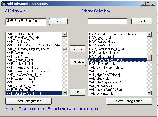
40 In ProCAL: Menu Advanced, add this variable. Our idle speed controls via IAC motor is a close-loop control. It reads the actually engine RPM and compares it to the target idle speed, and adjust the idle air correspondingly, and maintain the target the idle speed. Note: The idle speed certainly cannot be set too high or too low. For example, if your engine idle RPM (OEM setting) is 1500 RPM, and you change it to 3000RPM, it will not work, and you may have an oscillating RPM. If you set the idle RPM too low, like 1000rpm, it may end up stall frequently. How to calibrate the stepper motor position to get a desired idle RPM? And how to fix the issue after the engine started, like, the idle RPM is too high or too low? You need to tune the stepper motor position, MAP_StepPrePos_Tm_N, according to the following method. Note: the default stepper motor position is intentionally over- tuned, meaning, and more idle air than necessary. This is to make the initial start easier. If the idle RPM is too high after start, you need increase the stepper position value to reduce the idle air; If the idle RPM is too low after start, you need reduce the stepper position value to get more idle air. Adjust idle motor desired position; you need to do some advanced tuning, follow the below steps. (1) Add advance calibration: MAP_StepPrePos_Tm_N Confidential ECOTRONS Page 38

41 Confidential ECOTRONS Page 39

42 Find the variable: MAP_StepPrePos_Tm_N on the left side, then click Add>>. The variable appears on the right window. Click "OK" Confidential ECOTRONS Page 40
43 (2) Choose "list": In the interface Right Click, then click "Display type->list" In the list view, right-click, to Click "Show All Variables" Confidential ECOTRONS Page 41

44 Then Confidential ECOTRONS Page 42
45 Note: The value of "StepPosDsr" is the desired value from the table of "MAP_StepPrePos_Tm_N", based on the engine temperature "Tm". "StepPos" is the actually stepper motor position when engine is running at idle with the desired RPM. You want to tune the StepPosDsr as close as possible to StepPos at certain engine temperatures. For example: If engine temperature is 50 C, and the "StepPosDsr" value is 170 from the table, when engine is at idle with the desired RPM; the "StepPos" value is 290. So you can change the cell value to 240 at 50 C (the value is smaller than 290, the difference is about 50 steps, to have some room, for better engine start). Confidential ECOTRONS Page 43
46 You can also change the value in the table when "Tm" is higher than 50 degree Note: Increase the cell values in the table; you will get lower RPM. This means the bigger the stepper motor position, the less idle air. Confidential ECOTRONS Page 44
 is 390, this means, the stepper motor has went to the largest position, if the idle RPM is still high, please check whether it has air leak, or the stepper motor connector is not")

47 (3) After you change the value, then "Burn to ECU" If the file downloaded successfully, lower left corner will pop up message "Burn to ECU Successfully Note: Usually, the value of stepper motor position (StepPos) is 390, this means, the stepper motor has went to the largest position, if the idle RPM is still high, please check whether it has air leak, or the stepper motor connector is not connected well, or something wrong with the stepper motor. The way to check stepper motor is take out it from throttle body, place a side, start to run engine, to see the stepper motor whether is working, and when key-off the ECU, the stepper motor will go to the smallest position and then go to the default position, if the stepper motor doesn t work, it means, the stepper motor is damaged or something wrong with the ECU. Confidential ECOTRONS Page 45
48 3.4 Idle Controls via ignition timing Note: If you do not have our ECU-controlled ignition, or if your engine is not recommended for ECU-controlled CDI (2-stroke engines, for example). Or our ECU does not support ignition controls for your engine; skip the rest of this part (ignition controls). For throttle bodies (28mm for example) that do not have an IAC motor. The idle speed can be controlled by the ECU via ignition angle adjustment. This is only to adjust the small idle RPM deviation. The mechanical idle air screw must be adjusted to a good position that your idle RPM is a little higher than you desired when the engine is warmed up. Then the idle ignition angle can be retarded, and reduce the idle RPM at fully warmed up. At cold engine, idle ignition angle is likely at the optimum advanced angle, so that the idle RPM can be at your desired RPM even with a cold engine. For example, your idle ignition angle will be 9 degree CrA positive when it s cold. And it could be -7 degree CrA, a negative value, when it is fully warmed up. Idle speed controls via ignition angle controls (only possible if you have ECU-controlled ignition system). Why do you need the ECU-controlled CDI for idle speed control? After you have a stable running engine with the fuel control only, now it's time for you to add our CDI box. Because it will help to lower down the idle RPM after engine warm-up. The strategy is to have enough idle air to start in cold and stable Confidential ECOTRONS Page 46
 Then the strategy is to retard the spark advance to lower down the idle rpm once the engine is warmed up. It reduces the engine torque because of later sparks.")
49 idle in cold first. But that amount of air is a little more than necessary for the warm engine. (That's why you get a high idle rpm at hot but a low idle rpm at cold.) Then the strategy is to retard the spark advance to lower down the idle rpm once the engine is warmed up. It reduces the engine torque because of later sparks. (This also indirectly helps to reduce the emissions). Furthermore, this gives some torque reserve for possible high idle requests (for example, to prevent undercharging). And this also helps the launch, because once you open the throttle, the spark advance can be immediately goes to the optimum, and you get big torque increase! Pre-defined idle ignition angle map MAP_IgaIdc_N_Ld : when engine runs in idle, (throttle body is fully closed). There are also two correct ignition factors based on battery voltage and engine temperature. CUR_dIgaIdc_Tm, CUR_dIgaIdc_Ub Confidential ECOTRONS Page 47


50 The pre-defined idle ignition output angle = MAP_IgaIdc_N_Ld + CUR_dIgaIdc_Tm + CUR_dIgaIdc_Ub And the close loop ignition angle control for idle speed control is based on this pre-defined ignition angle. EFI system without an IAC motor, and without ignition control If the idle air is too much or too less, it leads the Engine idle RPM too high or too low. Because ECU has no way to control the idle RPM, in this case, you may have to start with a high idle RPM and later on, to fine tune the throttle mechanical stop position or idle air screw position to get a compromise of idle RPM. Confidential ECOTRONS Page 48
51 If the engine idle RPM is super high, like 3000rpm, ECU will cut the fuel, and the RPM may go up and down. 3.5 Idle fuel too rich because of minimum injector pulse width Q: How and why to adjust fuel injection time in idle? No matter how much you have changed the base fuel mapping for idle, ( via VE table or TPS Load table), the engine still runs too rich. It seems no effect even you put the 0 in the table. It may be because the minimum fuel injection pulse width is limited. You need to change that limit lower, VAL_tInjMin. This calibration basically defines the minimum pulse width that can open the injector. This is the physical limit of an injector, usually in 1ms to 2ms ranges. Go to "menu->advanced->add Advanced Calibrations to add the VAL_tInjMin. And decrease this value according to the actual engine running. This value by default is 2ms; or 2.2ms including the battery voltage compensation. The reason to have a 2ms min pulse width is because the injector has a better flow rate when it is bigger than 2ms. For many engines, the min pulse width could be smaller. Usually you can set it to 1.5ms or 1.0ms as the extreme minimum. Anything smaller than 1ms, you may not have fuel injection at all. For example: Confidential ECOTRONS Page 49
52 Confidential ECOTRONS Page 50
 With a NB O2 sensor.")
53 Q: How do I know whether it is rich or lean? You can use the following method to know whether the engine runs too rich or too lean with a NB O2 sensor or a wideband ALM. Also you may know it by smelling the exhaust gas when it is too rich. (1) With a NB O2 sensor. You can read the voltage of the NB O2 sensor in the ProCAL gauge, O2S; to know whether it is rich or lean. ulsb: signal of lambda sensor, in the List of variables. If it is higher than 0.45V, the engine runs rich. If it is lower than 0.45V, it runs lean. Confidential ECOTRONS Page 51
54 Confidential ECOTRONS Page 52
55 (2) Read the AFR by using an ALM gauge, which you can buy from ECOTRONS. You can also read the real time lambda (LamWO2) in ProCAL, for which you need connect the ALM to ECU through the EFI harness. With the ALM, the advantage is that you can read / log the real-time AFR or lambda value, and even have Ecotrons autotuning feature. Confidential ECOTRONS Page 53
56 Chapter 4 Open-loop and closed-loop fuel control 4.1 Open Loop Fuel Control What is open loop fuel control, why do we have it? Open loop fuel control is to run the engine without installing the O2 sensor. The reason we need to run it is a precautious step to protect the O2 sensor; to have a stable engine running before plugging in the O2 sensor. A good practice is to start and run the engine in the open loop mode, especially if your engine is very different than our base calibration engines (like a scooter GY6 150cc, which is the mostly tested engine). Or you have modified your engine significantly, like a big bore kit, a high cam, or a bigger intake manifold. All these difference will cause the big deviations in the air charge model pre-loaded in the ECU. Close-loop fuel control and self-learning is only supposed to correct the small errors from engine to engines. The big difference cannot be learnt by the ECU and could lead to the oscillations, or unstable running. Without a comparatively stable engine running in open-loop, the exhaust from the engine could be erratically rich or lean or have fuel flooding, and random moistures in the exhaust, etc. These could damage the O2 sensor before you even have a chance to run close loop controls. In open loop mode, ECU is reading the MAP sensor signal, TPS signal, and temperature signals to calculate the fuel, and control the fuel comparatively precisely. Confidential ECOTRONS Page 54
57 In open loop mode, you can drive the vehicle around, and tip-in, tip-out, and you can do almost everything, except that the ECU does not really know whether you are running rich or lean. And the ECU cannot self-learn the engine for variations. The self-fine-tuning of the fuel is not happening. Even in open loop mode, if tuned well, an EFI engine can run much better than a carb engine, NO QUESTION. Many OEMs have open loop EFI engines certified with EPA / CARB emission regulations. The key is the tuning. What if I cannot get a stable engine running in the open loop mode? If you "smell" it lean, a quick and dirty fix is to enrich the fuel with the global factor: "VAL_fFlApp". And once you have a relative stable run, you can detune this factor by using other parameters. If your idle speed is too low, and you cannot maintain the stable idle RPM, go to Chapter 3 (idle air adjustment). For open loop tuning, you can find the details in Chapter 5. But you need to know what a close loop control system is first. 4.2 Closed Loop fuel control Q: How to tune the close-loop fuel? A: You do NOT need to tune it. You only need to make sure it's happening. ECU will automatically tune it (with the O2 sensor). Q: How do I know it's in close-loop controls? First, you need to know a little bit of the O2 sensor. Confidential ECOTRONS Page 55
58 The O2 sensor indicates lean or rich by a voltage signal. When the O2 sensor is not active, the voltage should be about 450mV (or 0.45V); When the O2 sensor indicates rich, the voltage should be > 450mV; When the O2 sensor indicates lean, the voltage should be < 450mV; That's right! It s a narrow band O2 sensor. The wideband O2 sensor is too expensive to be included in the base kit. We do have a wideband kit, ALM, for your tuning purpose. When you see the O2 sensor voltage oscillating up and down around 450mV, that means the close-loop control is active. Q: How do I see the O2 sensor voltage? Easy way: in ProCAL, among a bunch of green/black gauges, there is an O2S gauge indicates the voltage. Better way: You need to log the data and play it back to see what's going on. In Data Analyzer, check the signal "ulsb", which is "voltage of lambda sensor (O2)". Q: My O2 sensor voltage is always 450mV (even after warm-up, 3 minutes later), what's wrong? Possible reason #1: you don't have it connected; Possible reason #2: the sensor is broken, or the wire is broken; Read the diagnostic DTC in ProCAL. Confidential ECOTRONS Page 56
59 Q: My O2 sensor voltage is always greater than 450mV, why? You are running rich all the time. Case 1: for many engines, during idle, it has to run a little rich, just because the injector size is not small enough. You are running in the minimum pulse width (calibrated as 2ms). This is OK. Case 2: you are running rich at all operating conditions, idle, part-load, WOT, etc. This could be caused by: you have enriched too much or you have some wrong calibrations. Check your enrichment factors VAL_FlApp; you fuel injector size, your engine displacement, etc, in ProCAL. Case 3: The base engine calibration is way off for your engine. The ECU self-tuning is only capable of fine-tuning. You need to do some advanced tuning. Read the later chapters. Case 4: The sensor is broken, or the wire is shorted. Q: My O2 sensor voltage is always smaller than 450mV, why? You are running lean all the time. It may happen if you have fuel supply issues. For example, your fuel pump is having air bubbles; or the fuel pressure is not enough; or the pressure regulator is malfunctioning; or the battery voltage is too low, etc. You have wrong calibrations. Check you fuel injector size, your engine displacement, etc. The base engine calibration is way-off for your engine. The ECU self-tuning is only capable of fine-tuning. You need to do some advanced tuning. Read the later chapters. Confidential ECOTRONS Page 57
60 The sensor is broken, or the wire is shorted. Q: How long does the ECU need to do the self-tuning? ECU self-tuning is only possible if you have a stable engine running in active close-loop controls. (meaning, engine has warmed up, O2 sensor is working, system is fault free, open-loop control is in the ball-park of the stoic AFR; close-loop is active, etc). It does not take long for the self-tuning. It takes a few minutes for every different operating condition. The key is to run the engine in a steady-state and traverse though the common operating conditions (idle, part-load, high-load, WOT, etc.) There are 2 key signals for you to check the self-tuning progress: "flcad" and "OfsLcAd". When you see they are slowly changing, the self-tuning is in progress; when they settle down at some non-1 value, the self-tuning is kind of done. Note: This self-tuning is based on the Narrow Band O2. It only adjusts small errors. It only works if the base fuel mapping is good. Note: This self-tuning is a life-long continuous process. It changes very slow, and takes only effect of long term factors Note: During start and warm-up process, the engine is running in open-loop mode; the self-tuning only starts in the close-loop mode after the O2 sensor is warmed up (see the graph below): Confidential ECOTRONS Page 58
61 Confidential ECOTRONS Page 59
62 Chapter 5 VE table and Load table tuning Note: EFI is an advanced technology compare to the carbs. It requires a thorough understanding of the electronics and software strategy to be able to tune the system. Please educate yourself on the basics of engines and electronic fuel injections. There is tons of info on the internet, and all you need to do is find appropriate levels of materials and read them. The first concept you need to understand is the "Volumetric Efficiency". Warning: some users tried to tune the volumetric efficiency or throttle based fuel mappings, without fully understanding the EFI system, and ended up with the worse-running engine. Volumetric Efficiency VE table Volumetric efficiency is probably the most important characteristics of an engine. It determines how efficient the engine is sucking the air into the cylinder, and therefore, how much torque it can generate, given the certain spark advance and air-fuel ratio. It is the fundamental calibration of the engine tuning. By definition, volumetric efficiency is the fresh air mass in the combustion chamber divided by the total air mass in it. Basically there is always some residual combustion gas trapped in the combustion chamber at the end of the engine exhaust stroke. The total air mass in the cylinder is the sum of the fresh air and the residual exhaust gas. To know exactly how much fuel you need to inject and to mix with the air in the combustion chamber, you have to know how much fresh air is in there instead of the total air mass, and that is why you have to know the volumetric efficiency. Confidential ECOTRONS Page 60
63 With a MAP sensor based system, you can measure the pressure in the intake manifold, and use that as the pressure in the combustion chamber, and together with the intake air temperature, and engine displacement, you can calculate the air mass in the combustion chamber. This is called by the auto industry as Speed Density" method. Following the ideal gas law: m = PV / RT m - Air mass P - Pressure V - Volume or engine displacement T - Air temperature R - Gas constant Once you know the manifold air pressure, intake air temperature, and the volumetric efficiency, you can calculate the fresh air mass in the cylinder and therefore the fuel quantity that needs to be injected. Unfortunately, volumetric efficiency is not able to be measured directly with any sensor. You'd have to calibrate it one operating-point (RPM vs MAP reading) at a time. The best way to tune volumetric efficiency is to put your engine on a dyno and use an accurate wideband air-fuel-ratio (lambda) meter to measure the mixture, and back-ward calculate the volumetric efficiency. Confidential ECOTRONS Page 61
64 However, knowing most people don't have access to a dyno, we can propose a coarse way to tune the volumetric efficiency. If you have a wideband controller, you can run the engine with the wideband controller together, or ride the bike in a steady state (comparatively constant throttles and RPMs); at a certain MAP signal and RPM, you can tweak the volumetric efficiency table until you get the stoic AFR read from your wideband controller. Make sure you have an accurate and reliable wideband controller, or you could end up with wasting your time. If you don't even have a wideband controller, you can use an even coarser way to tune it. Use the narrow band O2 sensor, which comes with the kit, and read the O2S gauge, lean or rich, at certain MAP signal and RPM, tweak the volumetric efficiency until O2S gauge indicates an oscillating voltages, up and down around the 450mV. Note: NB O2 based tuning is only possible if you have everything running normally and in close-loop control. LOAD based system To know more about the advance tuning with our EFI kit, you need to understand what the "LOAD" is. "LOAD" by definition is the actual air mass charged into the cylinder divided by the ideal air mass that could be filled into the full cylinder. What is the ideal air mass? When you have your cylinder fully filled with the fresh air at sea level (barometric pressure = 1 bar), and at the temperature of zero degree C (air temperature = 32 F), the mass of the air in the cylinder is the ideal air Confidential ECOTRONS Page 62
65 mass. In other words, if your engine displacement is 150cc, the idea air mass is the 150cc fresh air mass at standard conditions (1 bar, 0 degree C). "LOAD" is a relative value, in percentage, unit-less. "LOAD" is not the throttle position, because you can have different air mass in the cylinder at the same throttle position. Why making it so complicated? Because it is the only way, the RIGHT way, to control the engine. "LOAD" tells the ECU how much fuel is exactly needed for the desired air-fuel-ratio. Because you can only calculate the fuel quantity, if you know how much air is in the cylinder. "LOAD" based system makes the tuning process universal for all engines! It does not matter how big or how small your engine is. "LOAD" based system makes the EFI system modularized. The subsystems can be tuned independently (namely air subsystem, fuel-subsystem, ignition-subsystem, etc.) You may say: "Hey, I can just use the throttle position and RPM, to map the fuel pulse width on the dyno". While, you will end up re-tune all your mapping for some small things that you overlooked, or any small changes of the engine. You will have to start the tuning for a new engine from the scratch every time. LOAD based tuning makes most of our tuning data portable from one engine to another, with minimum changes. LOAD based tuning is the only professional way to tune. Confidential ECOTRONS Page 63
66 TPS based LOAD mapping Once you know what the "LOAD" is, you can tune the TPS based load mapping. Our system do not let you map the fuel pulse width directly out of the TPS / RPM table, because it is too coarse, and it is affected by too many factors (temperatures, altitude, speed, AFR, etc.). It may seem easier to map the engine in the coarse way, but it actually costs more time and efforts later on. You ll pay for that short-cut sooner or later. Our system let you map the "LOAD" out of TPS/RPM table, and then the load is used everywhere else as the base inputs (fuel, ignition, lambda, etc). Why? Because LOAD is the most representative physical variable for air charge in the cylinder. Throttle position is not even proportional to the air mass. It has a non-linear relation to the air mass (if you know some math ). LOAD is normalized against the air temperature, and altitude, and pressure. This means, you base LOAD mapping is not affected by the altitude, temperature, density, etc. Those factors will be added in later. This is the fundamental of modelbased-design, a modern method used by Ford and GM, etc. engineers. The way to calibrate the LOAD mapping is similar to the "volumetric efficiency" table. The best way is to use an engine dyno. If not, use a wideband controller, and if not, use the narrow band O2 sensor to do "estimations". At certain throttle position, and RPM, tweak your LOAD output, until you have a good AFR. This is called "Alpha-N" model by the auto industry. Confidential ECOTRONS Page 64
67 Blended Speed-Density and Alpha-N methods So, "Speed-Density", or "Alpha-N", which method is better for engine controls? There have been too many debates on this. Just google it. But the truth is: neither is perfect. You need both. You need blend them together to have the best engine controls, especially for high RPM, sporty motorcycle engines. As common sense, MAP sensor is a direct measure of air mass into the cylinder, while TPS sensor is an indirect measure of the air mass. It seems MAP sensor based "speed-density" is better than TPS based "Alpha-N" method for air charge detection. This is true at low RPM and small loads when the MAP sensor signal has enough resolutions and the air mass calculated based on the instant manifold pressure is more accurate than the estimated by TPS position. TPS based air mass estimation has very poor resolution at low throttle opening. A small throttle position change at low throttle can cause big air mass change. But as you may have noticed, small engines' manifold pressure is changing so dynamically, there is no "stable, constant" MAP signal; even you hold the throttle position unchanged. This becomes worse when you have large throttle opening, and you are running more than 6000 RPM. MAP sensor signal becomes un-stable and even not usable. For motorcycle sporty engines, at large throttle opening, which is usually accompanied by high RPMs, the air flow in the manifold is so fast, that the pressure change cannot be detected by MAP sensor any more. The result: you open the throttle more, but your MAP sensor gives you the same pressure reading, which is certainly wrong, because you have more air flow into the cylinder. In this situation, you must use "Alpha-N" method to calculate the air charge. Confidential ECOTRONS Page 65
68 So, in short, you should use "Speed-density" for low RPM, low loads; but use "Alpha-N" method for high RPM, high loads. This is exactly how our system works. We have a TPS characteristic curve that is based on RPM to split the fuel mapping between the "speed-density" and "alpha-n" methods. This curve is the threshold of TPS, that below it, you use "speed-density", and above it, you use "alpha-n". The curve is dependent on RPM. You can find this curve in the advanced calibrations in ProCAL (this calibration is only available for certain users): ProCAL advanced add advanced calibrations; Add: CUR_TpsUnTp_N "Characteristic curve, TPS threshold, air flow is un-throttled and/or pressure change is insensitive." Too complicated? I don't want to tune both tables, How about just one table? Of course, you can just use one method: "Speed-Density", or "Alpha-N". Only you don't have as much accuracy as the blended method. But most users do not really need that much of accuracy. Using one method is often good enough. Confidential ECOTRONS Page 66
69 If you engine max RPM is less than 8000RPM, "speed-density" method often gives good enough controls without using "alpha-n". Actually most of our base engine calibrations use the "speed-density" over the whole load / speed range. This means you only need to tune the VE table. Some other users prefer to using TPS based fuel mapping. And use MAP sensor only for Baro pressure reading (therefore adjust fuel for different altitude). This is especially true for 2-stroke engine tuning. As you know, 2-stroke engine does not have much meaningful manifold pressure to be used as air charge detection. In this case, you only need to tune the "TPS based Load Mapping" table. The disadvantage of "Alpha-N" method is that it does not adapt to the small changes in the intake air systems. Say, a small air leak will cause your idle AFR deviated. For a sporty, high RPM engine, like Kawasaki Ninja 250r, which has a RPM range of 1500rpm rpm, the blended "speed-density" and "alpha-n" is a must to have a good control over the wide range. Specific examples: Ok, you have read and known the above information, let's try to tune it. If your engine is running rich or lean in different throttle positions, you need do some advanced calibrations. There are two fuel mapping tables, one is "RAM_MAP_fVe_Map_N" which is based on pressure signal "Map" and RPM, the other table is RAM_MAP_LdTp_Tps_N" which is based on Tps and RPM. Confidential ECOTRONS Page 67
70 For four-stroke engines, the default fuel mapping usually is volumetric efficiency table (MAP_fVe_Map_N), at least for all low RPM and mid-range RPM. For high RPM and WOT, it is based on "MAP_LdTp_Tps_N". The split between the 2 tables is defined in "CUR_TpsUnTp_N" : If the throttle position (Tps) is bigger than the value of the table, it will be changed to use the Alpha/N model, otherwise it will use VE table. Example: (1) You can use NB O2 sensor voltage in the closed loop control to know whether it is rich or lean. Confidential ECOTRONS Page 68
71 Figure 1 Confidential ECOTRONS Page 69
72 Note: flc is the factor of lambda control, when closed-loop is active. It automatically changes based on the O2 sensor feedback. If it is smaller than1 for a long time, it means the default VE table value is too bigger; you need change it to a smaller one to reduce the fuel quantity. (2) Using the wideband ALM, you can read the AFR or lambda directly, and also log the real-time lambda (lamwo2) in ProCAL. For details on how to integrate the wideband ALM to the ECU and enable the ALM based auto-tuning, please download our document of ALM-ECU integration Manual here: Confidential ECOTRONS Page 70
73 Figure 2 You can change the VE table value based on "Map" and "N", and adjust MAP_LdTp_Tps_N based on "Tps" and "N". You can read the value of "Map" and "N" in ProCAL (Go to menu->variables->display Type->List). Confidential ECOTRONS Page 71
 =0.")
74 NOTE: If you want to tune the value of VE table or Alpha/N table, the engine must be warmed up, there is no enrichment factor, and you set it to ECO mode with the NB O2 sensor. Try to calibrate one cell value now, N=6929, Map=475, flc (Or lamwo2) =0.75 To calculate the fuel injection quantity within the red circular area, for example, at 6929 RPM and 475 Map, because it is rich, and needs to reduce the value of this area to get less fuel quantity, according to the O2 sensor factor; you can multiply the value of flc or LamWO2 to the cell value and hit ENTER. See below: Confidential ECOTRONS Page 72

75 Note: the VE table and LOAD table can be calibrated on-the-fly, meaning, it takes effect immediately. You can use the same method to calibrate all other cells of the table, when you have finished the calibration, the table must be manually made smooth and burn it to ECU. It is critical to have a smooth transition from on operating point (one cell) to the next in the VE table, never ever leave a spike in the table (a good way is to export the table to EXCEL and plot 3D surf, and manually smoothen out any spikes). Spikes are no good for engine controls. You can also use the real-time lambda (ALM output) to calibrate the table. Make sure to use the engine steady-state running signals. Confidential ECOTRONS Page 73
76 The method to calibrate the MAP_LdTp_Tps_N (Alpha/N model) is same as MAP_fVe_Map_N, only different in the dependency of "Tps" and "N", throttle position and RPM. Note: To make it easy on the time-consuming tuning, understand you don't want to tune each cell, we developed the "EXPORT" functions of the tables. You can modify the whole table in Microsoft EXCEL! Right click the table, select "export", it will save the table in the CSV format. And you can do the editing in Excel, which most users are very familiar. After you done the editing in EXCEL, you right click the table in ProCAL again, and select "import", select the CSV file you saved, and it will import the whole table back in. It is so easy to edit the table in EXCEL that it has become a must to use this feature to do the tuning. You can also do the 3D plots, and use EXCEL math functions to tweak the cell values, and smooth out the spikes. You can calibrate CUR_TpsUnTp_N to choose when to use Alpha/N model. If you want us to help you to tune the EFI, Please log data at different conditions, and have comparativel steady state driving at different throttle positions. For two-stroke engines, the default fuel mapping is Alpha/N method, "RAM_MAP_LdTp_Tps_N", so if you want to calibrate the fuel quantity for a 2-stroke engine, you just modify the LOAD table only. The procedure is same as the fourstroke system. Confidential ECOTRONS Page 74
77 Some notes before tuning the fuel mapping tables: 1) The engine has finished warm-up, this means it doesn t have other enrichment factor. You can see the value of fprectl, when the fprectl is 1, you can go to tune the tables. 2) The fuel pressure must be enough and stable, the fuel pressure is about 3Bar (43psi). 3) When you tune the value of the fuel tables, you need read the lambda (LamWO2) in the stable condition; stable throttle position and RPM, not use the lambda in accelerate and decelerate to tune the tables. Confidential ECOTRONS Page 75

78 Chapter 6 Ignition Timing Tuning Pickup (sensor) to TDC angle If you are using our ECU and our CDI to control the ignition timing (spark advance), based on a single pickup (sensor), you must identify the offset angle between the pickup pulse and the engine TDC. Only by knowing, this offset angle can the ECU control the CDI to fire the ignition at the right timing. This offset angle is usually about 29 degree crankshaft angle before the TDC, for most CDI ignition systems. If you don t know this offset, or if you have trouble to figure out this offset angle, you better keep the stock ignition system and use the EFI to control fuel only. This way, you can start the engine, and worry about the ignition system later. For the information of how to configure a Crank sensor with a multi-tooth trigger wheel, refer to Chapter 2. How do I set the offset angle in ProCAL? Please add this advanced calibration variable in ProCAL: ProCAL Advanced Add Advanced Calibrations: Default: VAL_dIgaGap2TdcAdj = -29 CrA (crank-shaft angle) Confidential ECOTRONS Page 76
79 This defines the offset between your trigger pulses to TDC. The default is -29 CrA. That means 29 degrees in advance to the TDC. How to find the offset angle: Confidential ECOTRONS Page 77
80 Note: It is a negative value. -29 degree of crankshaft angle (CrA); here negative means before TDC. This number (-29) is OK for most scooter/bike engines, so you don't have to change. You can use a timing light to verify whether the ignition angle is close to what should be. Note: VAL_dIgaGap2TdcAdj has been changed to the positive value with our newest software. Confidential ECOTRONS Page 78

81 You can find out whether it should be a positive value with your A2L file, such as: S33_H1_L48_Cr17_AT3.4_E4.a2l if the number is bigger than Cr17, for example, Cr18 or Cr19. it means it is the newer software; the VAL_dIgaGap2TdcAdj should be positive value. Start ignition angle If you use Ecotrons CDI to control ignition, the default start ignition angle may be not suitable, if it has start ignition issue, you can try to modify the start ignition angle table Ignition; it is based on the engine temperature at start. Please add this advanced calibration variable in ProCAL: ProCAL Advanced Add Advanced Calibrations: Angle in start: CUR_IgaSta_TmSta When engine go to start, the ignition angle is the value of CUR_IgaSta_TmSta Basic Ignition Angle mapping Basic ignition angle is the spark advance that you can run the engine at the max torque (at given LOAD and RPM), without causing the knock. Confidential ECOTRONS Page 79
82 Actually it is not 100% optimized. There are 2-5 degrees of buffer reserved to protect the engine. You cannot run 100% optimized spark advance unless you have a good knock control systems (with knock sensors, for additional cost, etc). There is a 16x12 ignition angle table (based on RPM and Load) for you to tune at different operating conditions. There are other tables, to adjust ignition angles dependent on temperatures, AFR, altitude, etc. It is fully programmable ignition control systems, compared to a pre-set factory ignition curve only dependent on the RPM. The 16x12 basic ignition table is dependent on RPM and Load, and you can tune it to whatever curve, or actually "surf" as you want. Factory CDI timing is usually a fixed curve - more advance at higher RPM. That's it. ECU controlled ignition angle has much more flexibility: it also takes into account of AFR (rich or lean), temperatures (cold or hot), altitude, etc. You need to read through the strategy book to understand how these factors affect the final ignition angle output. Confidential ECOTRONS Page 80
.")
83 In ProCAL: Menu calibrations ignition system basic ignition angle Note: The default ignition table is very close to the best ignition angle, so if you want to change it, please adjust it in a small step and range, such as 1 degree or 3 degrees (For example, if the default value is 36, you can change it to 38). It protects the engine from too aggressive ignition angle, which can damage the engine. Confidential ECOTRONS Page 81
 that you can")
84 Minimum Ignition Angle misfiring. Minimum ignition angle is the latest spark retard angle (refer to TDC) that you can still run the engine without Confidential ECOTRONS Page 82
85 Other Ignition Angle Adjustment Basic ignition angle will be adjusted according to temperature, altitude, lambda, knock limit, etc. That's probably why sometime you see the actual ignition angle is not the one you filled in the basic ignition able. It can be something in the middle of basic angle and minimum angle. Confidential ECOTRONS Page 83
86 Chapter 7 Advanced Tuning 7.1 Transient fuel To improve the performance of the throttle response, you need to change the transient fuel. When you open the throttle, if you feel the bike bogs or pops or doesn't have much power, it may be too rich or too lean, you can read the AFR/lambda by using the ALM wideband senor. Then do some advance tuning according to the below instructions. Add two calibration variables by using the advanced calibration menu, CUR_Wf_Ldp" and" VAL_fTrsRedS" "CUR_Wf_Ldp": the wall film fuel quantity during the transient, depend on the predicted LOAD. VAL_fTrsRedS": reduction factor of the short-term transient fuel Our transient fuel tuning, is based on the Wall film model. Wall film fuel is the fuel stuck on the intake manifold wall or combustion chamber corner, clearance, which is not participating the combustion. Then you open the throttle or close the throttle, the wall film fuel will increase or decrease, and therefore change your desired AFR. The transient fuel tuning is to model this wall film at different Load conditions, and then compensate the fuel that is caused by the wall film fuel changing. The wall film fuel is modeled based on the Predicted LOAD. Predicted load is the engine load of the next combustion cycle. You must use predicted load, not the current load, for the next cycle s fuel calculation. This is a whole advanced engine control theory, if you are interested. Confidential ECOTRONS Page 84
87 Below are a couple of examples of transient fuel tuning. Confidential ECOTRONS Page 85

88 Confidential ECOTRONS Page 86

.")
89 You can calibrate the "CUR_Wf_Ldp" value based on the LdPrd, you can read the value of LdPrd in ProCAL. You can change the wall film quantity according to LdPrd before increasing the throttle and after increasing the throttle. The delta of the wall film quantity at different LdPrd is the base transient fuel. If you see lean conditions at the throttle opening, that means you need to add more wall film at high Load conditions (big LdPrd). You can also try to adjust the value of "VAL_fTrsRedS" to get different effects of the throttle opening conditions. Confidential ECOTRONS Page 87
90 "CUR_fwLdpMapTps_N" is a weight factor for PN model and Alpha/N model in transient conditions. Raise the value of CUR_fwLdpMapTps_N will make TPS-based prediction more weighting, when you increase throttle in acceleration condition. When you begin to calibrate the transient fuel, the basic injection table must be stable, the engine must run normally. And to calibrate it, you need to repeat the test to get a better performance. Advanced tuning for throttle blips If the response of throttle blip is not in favor, and you have the right software version from us for this issue, you can calibrate it by yourself, and find a suitable value to improve the response (usually for the big displacement engine). Injection compensation variables for throttle blips: VAL_dtInjTpBlip_Max --- max delta injection pulse width in ms when throttle blip happens. VAL_dtInjTpBlip_Min --- min delta injection pulse width in ms when throttle blip happens. VAL_dTpsTpBlip_Min --- min delta Tps change in 20ms to recognize the throttle blip. (If the Tps change is bigger than VAL_dTpsTpBlip_Min, it will enable the function to add fuel.) VAL_NTpBlip_Max --- max RPM limited when throttle blip (If the RPM is higher than VAL_NTpBlip_Max when the throttle blips, there is no additional fuel) Confidential ECOTRONS Page 88
91 Dashpot functions for deceleration: And if you have the software for deceleration to avoid a stall issue with the stepper motor control system, you also can calibrate the below variables. Confidential ECOTRONS Page 89
92 VAL_McDashpot_DeltaDecrements: the step size of IAC ramp-down, range: 12-24; the bigger the value, the faster the ramp, but more likely to stall. VAL_McDashpotInitValue: initial position of the IAC motor for dashpot, range ; Note: You can find the variables in ProCAL if you have the correct A2L file, go to menu->advanced->add Advanced Calibrations. You need repeat the attempts to tune it. 7.2 Decel-Fuel-Cut-Off Our EFI system by default has enabled the decel-fuel-cut-off function. It is RPM dependent, when you release the throttle to idle and RPM is higher than the table value, it will cut the fuel injection. And you can adjust the table value to decide at what RPM to resume fuel. Menu->Calibrations->Fuel system->decal-fuel-cut-off Confidential ECOTRONS Page 90

93 Note: So if you want to disable decal-fuel-cut-off, you can adjust the table value to a bigger one. But don't disable the decal-fuel-cut-off, if you are running in a mountain area, and it may damage the engine in downhill driving because a lot of un-burnt fuel getting into the exhaust system. 7.3 Driver s desired lambda 1) Driver desired lambda is only feasible after you have the system running stably in close loop controls and the ECU has done the self-tuning. That means, the ECU can control the AFR in the vicinity of stoic AFR (14.7 for gasoline). Only after that, ECU can command a meaningful AFR other than the stoic. Otherwise, the driver desired lambda could have a big deviation from the actual lambda value. 2) Driver desired lambda is meant to give the user a way to command the AFR other than Stoic, either for performance purpose (more likely) or fuel saving purpose. Confidential ECOTRONS Page 91
94 3) Default value of desired lambda is as below table. It is enriched at high end. 1 means stoic AFR (14.7 for gasoline). 4) Desired lambda table can be activated by turning on the "RICH" mode, by switching the "Performance switch" to ON position. By default, the engine is running in "ECO" mode; and the desired lambda table is not used. Some more comments on RICH mode: Rich mode only works well after ECO mode is tuned. RICH mode is actually an open loop mode, meaning, ECU will command the "desired Lambda based on the ECO mode tuning. It assumes you have tuned the base mapping like VE table and TPS Load table close to Stoic AFR at all conditions. It then divides the desired lambda on the top of the base fuel quantity. In RICH mode, you only tune the desired lambda table", which should between 0.8 to 1.2 ranges. This is nothing but a dividing factor on top of the base fuel mapping. For example, you base fuel mapping outputs a fuel quantity of 3ms pulse width, and your desired lambda is 0.9; then your final fuel pulse output is 3 / 0.9 = 3.33ms. Confidential ECOTRONS Page 92

95 Menu->Calibrations->Driver's demand->desired lambda Confidential ECOTRONS Page 93
96 7.4 Advance Calibration for engine timing If you use Ecotrons ECU to control ignition system, you may do some advanced calibration on the ignition system to get a good performance. Pickup type 1) One pulse per revolution. VAL_dIgaGap2TdcAdj: "Ignition angle adjustment from GAP to TDC, GAP is pickup pulse location." This is the first calibration you need to be sure. It determines the engine TDC position in regarding to the pulse generation. See Chapter 6, how to calibrate this variable. You can also adjust the injection timing, based on the pickup pulse. It is the mapping of MAP_InjAngEnd_N_Ld MAP_InjAngEnd_N_Ld" is the end of injection angle referring to TDC; it means the angle from injection end to the ignition TDC position. Confidential ECOTRONS Page 94
 generates AC pulses instead of square waves.")

97 2) How to calibrate the ignition timing and injection timing with a multi-tooth trigger wheel installed on the crankshaft? VRS sensor installation for the multi-tooth trigger-wheel The VRS (Variable Reluctant Sensor) generates AC pulses instead of square waves. The metal sensing element (sensor core) needs to align well with the multi-tooth wheel. See below for the examples. The tooth width needs to be bigger than the sensor metal core, otherwise, the VRS signal will not be correct, and ECU will the distorted VRS signal, and EFI could not work. Measure the signal + wire and signal wire output with oscilloscope (12-1 tooth-wheel) [Note:] CKP+: CH1 (yellow); CKP : CH2 (Blue) Confidential ECOTRONS Page 95
98 Confidential ECOTRONS Page 96
99 Trigger wheels supported Our EFI works with a wide range of multi-tooth trigger wheels. The typical trigger wheels have 36-2 tooth-wheel, or 12-1, 24-1, 36-1 or 60-2 tooth wheels. Here, 36-2 tooth wheel means there are totally 36 teeth with 2 missing teeth means totally 12 teeth with 1 missing tooth, and so on. Our ECU supports different combinations of total teeth and missing tooth setting. The total number of teeth cannot be more than 60; the missing tooth can be 1 or 2. Usually the higher the engine speed redline, the less the teeth. This is because at higher speed, the tooth signal becomes smaller and smaller, and eventually ECU cannot read it anymore. For most 2 stroke engines, 12-1 tooth wheel, or 24-1 tooth wheel is typical, because usually 2 stroke engines are high speed ones. For most 4-stroke motorcycle engines, the tooth wheel is 36-2 setting. If you want to have a good ignition control system, a high-tooth wheel is definitely way to go. And if you have the mechanical capability to add the tooth wheel to your engine, we recommend you to do so. For multi-cylinder engines, and special engines, such as a V-twin engine, if you want EFI system to control the ignition, you need to install the tooth wheel. Our CDI controlled ignition system is meant to be used for single cylinder engine. And the accuracy of the ignition timing is not as good as the trigger wheel based. Let s see one example with 36-2 tooth-wheel. Some calibration variables need to be defined: Confidential ECOTRONS Page 97
100 VAL_nTeethTot: Total number of teeth on the tooth-wheel. VAL_nTeethMiss: ---- number of missing tooth on the tooth-wheel. VAL_ToothTDC: tooth number of the ignition TDC for single cylinder. VAL_ToothTDC2: tooth number of Cylinder #2 ignition TDC for two cylinder engines. MAP_Iga_N_Ld: basic ignition angle table MAP_InjAngEnd_N_Ld- injection end angle table Below is an illustration of the 36-2 trigger wheel and the engine positions. Each tooth is 10 degree (360/36=10). The first tooth after missing teeth is marked as the #1 tooth. Confidential ECOTRONS Page 98
101 Confidential ECOTRONS Page 99
102 First you need calibrate the parameters of the tooth-wheel: VAL_nTeethTot=36; VAL_nTeethMiss=2; Four-stroke engine: 1) Single cylinder engine: You need calibrate VAL_ToothTDC VAL_ToothTDC is the tooth number of the ignition TDC. To find it: Rotate the engine crankshaft and make the piston at the TDC position, and count the tooth number after the missing tooth, which tooth is aligned to the VRS sensor. See the below picture, it is very clear. Confidential ECOTRONS Page 100
103 In the above picture, you can see the #11 tooth is at TDC, so VAL_ToothTDC=11 Confidential ECOTRONS Page 101
104 2) Tow-cylinder engines: You need calibrate VAL_ToothTDC, VAL_ToothTDC2 The method to calibrate two-cylinder engine is same as a single cylinder engine. One important thing is to find out how many degrees the two cylinders are separated. Use a V-twin engine as an example; the two cylinders are separated by 90 degrees. For 36-2 tooth-wheel, V-twin, a two-cylinder engine, the ignition TDC tooth of cylinder -1 is #11, and the two cylinders are 90 degree apart, so the ignition TDC of cylinder #2 is 450 (360+90) degrees after the Cyl-1 s. So the ignition TDC tooth of Cyl-2 is #56. Note: The value of the tooth number for 4 stroke engines is form 1 to 72, because 2 revolutions are one full engine cycle. The tooth number will increment by 1 into the next revolution, until 72. After number 72, the tooth number reset to 1. Confidential ECOTRONS Page 102
105 So VAL_ToothTDC=11, VAL_ToothTDC2=56. If the two cylinders are separate from 360 degrees, like a boxer or parallel twin engine: VAL_ToothTDC=11, VAL_ToothTDC2=47 Confidential ECOTRONS Page 103
106 Note: The method to calibrate 12-1, 24-1, 60-2, etc. tooth-wheels for four-stroke engines is same as to the 36-2 tooth-wheel. Confidential ECOTRONS Page 104
107 Two-stroke engines: 1) Single cylinder 2 stroke engines You need calibrate VAL_ToothTDC VAL_ToothTDC is the tooth number of ignition TDC. For example, for a 36-2 tooth-wheel, #11 tooth is the ignition DTC, so VAL_ToothTDC=11 2) Two-cylinder 2 stroke engines You need calibrate VAL_ToothTDC, VAL_ToothTDC 2 If the two cylinders are separate by 180 degrees, VAL_ToothTDC=11, VAL_ToothTDC2=29 (each tooth angle is 10 degree) Note: The value of the tooth number is form 1 to 36 for 2 stroke engines, because 1 revolution is one full engine cycle. The tooth number will be reset to 1 in the next cycle. The method to calibrate 12-1, 24-1, 60-2, and etc. tooth wheels is same as to the 36-2 tooth-wheel. Confidential ECOTRONS Page 105

108 Calibration of ignition timing and injection timing The ignition angle MAP table: MAP_Iga_N_Ld Injection end angle: MAP_InjAngEnd_N_Ld Both of them can be calibrated in the engine dyno or chassis dyno. Confidential ECOTRONS Page 106
109 7.5 Dual injectors advanced tuning Why 2 injectors it need for 2-strokes and high RPM engine? The whole idea of 2 injectors (one small, one big) is based on the need: 2-stroke engines have only half the time to inject fuel compared to 4-stroke (360 vs 720 degrees), and the 2-strokes usually (esp. high-end engines) have such a wide range of RPM ( rpm, for example). One injector is not able to cover the whole RPM range, simply because every injector has its physical limit: the fixed flow rate. If you use a big injector to cover the high end, then you will have too-rich idle. If you use a small injector, to have a good idle, then you don't have enough fuel for WOT. Given a certain inject flow rate, you can only run an engine either at low RPM range or high RPM range, but not both (from 2000 to 16000rpm). So, for 2-stroke engines with 10k-16k RPM, usually, we provide EFI system with dual fuel injectors, one smaller and one larger, the smaller injector is used start, idle, low RPM, and the larger one is used high RPM, and in WOT condition, the 2x injectors work together. The following is the working example, 1 cylinder, 2-stroke engine with RPM (128g/min and 190g/min). Confidential ECOTRONS Page 107
110 Control strategy: There is one important thing for two injectors system you need understand. For example, if the RPM is 10000, the time of 1 RPM is 6ms. (1 min=60 s=60000ms, 60000ms/10000RPM=6ms/RPM) If the first injector injected time (tinj0) is bigger than 4ms (6ms- VAL_tInjBrkMin), this means the fuel injection can t match the need of engine, it will change to the second injector to inject fuel. Otherwise, the first injector continues to inject fuel. If each injector can t match engine need, the two injectors will work together. Default setting: VAL_tInjBrkMin=2000 us=2ms You can adjust the fuel injection MAP table RAM_MAP_LdTp_Tps_N based on your engine running, the value of this table is bigger, the fuel will be more, otherwise, the fuel will be less. The ECU can t know how many fuel is enough, you need calibrate it. If it is rich, you can reduce the fuel injection. And you also can calibrate VAL_tInjBrkMin to decide in which condition to change to the #2 injector (Go to Menu->Advanced->Add Advanced Calibrations, to find the VAL_tInjBrkMin). Confidential ECOTRONS Page 108
111 7.6 Altitude tuning Our EFI system can work in different altitude, and it can use the Map (Baro) sensor to estimate the altitude, then to correct the fuel automatically, but it also needs some fine tuning. There is an altitude factor to correct the fuel injection, falt, it is a universal factor, and it is a multiplication coefficient to correct fuel injection. falt =Pam/1013, So, if you are at sea level, Pam is 1013, so the falt is 1,And at 5000 feet altitude, the Pam is 850hPa, so the falt = 850/1013, it is For example, at sea level, the fuel injection is 2000RPM, so the fuel injection will be 5*0.83 (falt) at 5000 feet altitude. Of course, the intake air pressure Map is also be different, this just explains to the altitude factor how to work. The falt is not used to correct fuel injection time directly, it is used to correct the fve and Tps based mapping, then to correct the fuel injection. Confidential ECOTRONS Page 109
112 Chapter 8 Sensors and actuators 8.1 Sensors characteristics calibration You only need to calibrate sensors and actuators if you are using the ones other than what we provide. (For example, you installed a throttle body from after-market or from another FI engine, which comes with the OEM's TPS, MAP sensors, and injector); or if you use our ECU only to replace the stock ECU on an EFI engine. The best way to tune the sensor and actuator's characteristics is to find the manufacturer's data sheets. If you cannot get them, here are the ways to get coarse data for them Injector characteristics Static flow rate: VAL_Qstat: injector static flow rate (g/min, or gram per minute) This must be found out from the manufacturer's datasheet. Or you have to hire a professional company to measure it. Menu->Calibrations->Fuel system->fuel injector characteristics Confidential ECOTRONS Page 110

113 Together, it may be necessary to find out what is the fuel pressure in the fuel rail, or high pressure line. Make sure the "VAL_Qstat" has the value which is associated with this fuel pressure. Otherwise it may need adjusted. Ask us how to Engine displacement VAL_vEng: volume of engine displacement (cc or milliliter) Menu->Calibrations->System parameters->engine displacement This might be the easiest one to figure out. Note: If it's a 2 cylinder engine, this value needs to be divided by 2. Meaning this is the single-cylinder displacement. Confidential ECOTRONS Page 111
114 8.1.3 MAP sensor Map: manifold absolute pressure (hpa) umap: voltage of MAP sensor signal (V) Map = umap * VAL_PmapGrd + VAL_PmapOfs Analog signal from the MAP sensor, umap, is converted into absolute pressure in hpa. the conversion is linear, with slope of VAL_PmapGrd, and offset of VAL_PmapOfs. "VAL_PmapGrd" and "VAL_PmapOfs" are calibrate-able variables in the ECU. To find out these 2 values, you have below options: Get it from the manufacturer, either from the vehicle manufacturer, or component manufacturer. Measure it yourself, and you need 2 pairs of (pressure vs voltage) data points: Use an accurate pressure gauge, measure the pressure point #1, P1, and at the same time use a multi-meter, measure the voltage of the MAP sensor signal wire, u1; Measure the pressure point #2, P2, and at the same time use a multi-meter, measure the voltage of the MAP sensor signal wire, u2; These 2 data points are preferred to be representative to the range of MAP sensor. Confidential ECOTRONS Page 112
115 For example; P1 can be the idle air pressure: 500hPa. Note: When measuring the pressure, create a stable vacuum. Small engine manifold pressure is too dynamic for this measurement. P2 can be the barometric pressure: 1013 hpa at sea level. Then VAL_PmapGrd = (P2 - P1) / (u2 - u1) VAL_PmapOfs = P2 - u2* VAL_PmapGrd Menu->Calibrations->sensor characteristic-> Map sensor IAT sensor IAT: intake air temperature sensor Ta: Tempearature of intake air ( C) Confidential ECOTRONS Page 113
116 uta: voltage of air temperature sensor signal (V) Usually temperature sensors are NTC type: negative temp characteristics: Assuming, as a first-order approximation, that the relationship between resistance and temperature is linear, then: ΔR = k * ΔT Where ΔR = change in resistance ΔT = change in temperature k = first-order temperature coefficient of resistance Contact us if you do not have sensor manufacturer's data. By these relations, you can calculate the below table and fill in ProCAL: Menu->Calibrations->sensor characteristic-> Air temperature sensor Confidential ECOTRONS Page 114
117 8.1.5 ECT sensor ECT: engine coolant temperature sensor Tm: Engine (motor)tempearature ( C) utm: voltage of engine temperature sensor signal (V) Usually temperature sensors are NTC type: negative temp characteristics: Assuming, as a first-order approximation, that the relationship between resistance and temperature is linear, then: ΔR = k * ΔT Where ΔR = change in resistance ΔT = change in temperature k = first-order temperature coefficient of resistance Contact us if you do not have sensor manufacturer's data. By these relations, you can calculate the below table and fill in ProCAL: Menu->Calibrations->sensor characteristic-> engine temperature sensor Confidential ECOTRONS Page 115

118 Calibration for your own temperature sensor (IAT or ECT): If you have the characteristic from the manufacturer, you can fill the table directly. If not, you need measure it by yourself. A rough but working one: put your temperature sensor into some coolant, which you can heat it up at different temp., and use a thermo-stat measure the coolant temp, and also measure the voltage with our software ProCAL, and fill in the CUR_Tm_uTm or CUR_Ta_uTa TPS sensor Tps: throttle position sensor (%) utps: voltage of TPS sensor signal (V) For throttle position sensors, you need to measure the idle position "utps1", and WOT position "utps2". Then find the values for VAL_uTpsMx and VAL_uTpsMn, to make sure that: +5V > VAL_uTpsMx > (utps v) Confidential ECOTRONS Page 116
 to reset the self-adaptation; For example, disconnect the ECU from the connector with key on.")
119 (utps1-0.1v) > VAL_uTpsMn > 0 TPS self-adaptation When will the ECU run the TPS self-adaptation? 1. When a new ECU is installed; 2. When either the TPS or the throttle body is replaced: 3. Your ECU cannot reach 100% TPS. 4. When ECU is first on after the TPS is mechanically adjusted. How to do TPS self-adaptation? 1. Power on, and disconnect the ECU (power-fail) to reset the self-adaptation; For example, disconnect the ECU from the connector with key on. 2. Power off, re-connect the ECU, and power on again. 3. Keep the throttle at idle position for more than 5s. Confidential ECOTRONS Page 117
 for more than 5S. Now you can read the TPS is almost 100% or 99.99% in ProCal. 5. Double check TPS in ProCAL.")
120 If you look closely in ProCAL, you can watch the TPS reading is changing from a small value to 0% by itself. Now you can read the TPS is 0% in ProCAL. 4. Keep the throttle at WOT (wide open throttle) for more than 5S. Now you can read the TPS is almost 100% or 99.99% in ProCal. 5. Double check TPS in ProCAL. It is 0% when the throttle is at idle position, and it is 100% when the throttle is at WOT position. Confidential ECOTRONS Page 118

121 8.2 Fault and Heal Power on the EFI system, and if the MIL lamp (LED) is on, it means there is an error in the system. Please use ProCAL to read DTC. For example Diagnostic Trouble Code: Fault1: There is something wrong with the MAP sensor! Map sensor report error, please check the connection. Fault2: There is something wrong with the TPS sensor! Confidential ECOTRONS Page 119
122 Throttle body position sensor error, please check the TPS connection, and see the sensor voltage of fully closed and wide opened (4.8V>uTps>0.2V) Fault3: There is something wrong with the O2 sensor! Narrow band O2 sensor error, please check the installation and connection, and see the voltage of O2S is range from 0 to 1V Fault4: There is something wrong with the CKP sensor! Pick-up signal error, check the connection Fault5: There is something wrong with the IAT sensor! Intake air temperature sensor error, check the harness connection Fault6: There is something wrong with the ECT sensor! Engine temperature sensor error, check the harness connection Fault7: There is something wrong with the VPWR! Battery voltage error, it he voltage of battery is low to 10V and high to 16V, it will report error TPS sensor diagnostic ECU reports TPS error 1) Connection problem The Throttle position sensor is not connected well, please check the wire and reconnect it. 2) The voltage of TPS is out of measuring range Confidential ECOTRONS Page 120
 Open ProCAL, then go to \"Variables Type ->List\" (2) Read the voltage of")

123 If the signal of TPS is out of range, you need to adjust it by using the following method (1) Open ProCAL, then go to "Variables Type ->List" (2) Read the voltage of throttle position Sensor :" utps" (3) Connect to ECU, to click "Run Start Measuring" (4) Remove the Tps sensor form the throttle body, see the below picture. Confidential ECOTRONS Page 121
 After installed, to mount the screw, it")

124 (5) Install the throttle sensor. (6) After installed, to mount the screw, it is better not to tight completely so you can adjust it conveniently. Confidential ECOTRONS Page 122

 (9) If the voltage of throttle sensor is not from 0.3V to 4.")
125 (7) When the throttle fully closed, to see the value of voltage of TPS by ProCAL. (utps> 0.3V) (8) When the throttle is widely open, to see the voltage. (utps<4.8v) (9) If the voltage of throttle sensor is not from 0.3V to 4.8V, you can rotate the sensor to adjust the voltage. Confidential ECOTRONS Page 123
 Reset the TPS position if Tps is not 0 when idle Key on the system and key on only, disconnect the ECU from the main harness and reconnect it with keeping power on.")
126 Note: The voltage of throttle sensor is normal in the range from 0.3 to 4.8V 3) Reset the TPS position if Tps is not 0 when idle Key on the system and key on only, disconnect the ECU from the main harness and reconnect it with keeping power on. Then you can see the Tps is changed to 0 when throttle is fully closed. 4) How to check the TPS signal rationality? With the TPS is installed, the output voltage should be 0.3~4.8V DC. You can tell whether the TPS is broken by reading the virtual scope of the ProCAL 1) Show the utps in the oscilloscope (right click on the list window). Confidential ECOTRONS Page 124

127 Confidential ECOTRONS Page 125

128 2) Connect to ECU, to click Run Start Measuring 3) Slowly open and close the throttle, and you can get a symmetrical curve on the virtual oscilloscope, which is 0.3V~4.8V, like picture 1. Confidential ECOTRONS Page 126

129 If the line is not consecutive, like picture 2, you should replace it with a new TPS sensor. Picture 1 Confidential ECOTRONS Page 127
130 Picture MAP sensor diagnostic If you have installed the EFI system and key on the bike, engine is not starting, the ECU reports Map error, and there are two possible causes. 1) Connection error The Map sensor is not connected intact. Please check it and reconnect it to ECU harness. 2) A bad sensor The Map sensor is broken. Read the signal in ProCAL to check it. Power on ECU and connect to ECU. Go to menu "Variables->Display Type->List". Then "Run->Start measuring" Confidential ECOTRONS Page 128
 is about 4.7V (1 Bar sensor); and about 1.8V (2.")
131 If the voltage of Map sensor (umap) is 0V or 4.99V, it shows that the Map sensor is broken, but makes sure the Map sensor is connected well at first. If the Map sensor is broken, contact us to get a good one. The normal voltage (umap) is about 4.7V (1 Bar sensor); and about 1.8V (2.5Bar sensor) when system is just powered on and engine doesn't start. 3) Fault indication when cranking engine If ECU reports MAP error (B_MapDrpErr=1) when the engine starts or is running. The possible reason is the intake air vacuum is too less or there is some leaking air. Confidential ECOTRONS Page 129

132 (3) First, check the Map sensor location, and connect the Map sensor to throttle body by a using a short hose. Check it for air leaks and make sure that it is sealed properly. Turn the idle air screw or stepper motor position to get more idle air. Change the value of minimum Map voltage drop "VAL_uMapDropIntkMin" during cranking. In ProCAL, go to "menu->advanced->add Advance Calibrations" Confidential ECOTRONS Page 130


133 Confidential ECOTRONS Page 131
134 Note: The value of "VAL_uMapDropIntkMin"cannot be smaller than 0.3V Temperature sensor (IAT & ECT) diagnostic IAT: Intake air temperature sensor ECT: Engine temperature sensor If ECU reports IAT or ECT error, there are two possible reasons for this Possible reason #1: the connect wire break off Possible reason #2: the temperature sensor is broken Note: If there is an error about the temperature sensor, please repair it or replace it as soon as possible, because it will affect the fuel injection, it may be too rich or too lean, and the engine can't run normally NB O2 sensor diagnostic If you have installed an O2 sensor and the O2 sensor signal is not changed, it still 450mv or bigger than 1V when engine is finished warmed up (engine is running about 3 minutes) and anything is connected well. It shows the O2 sensor is broken, please change another good O2 sensor. And if the system reports O2S error, and you also need to check the connection whether it is short or broken circuit. Confidential ECOTRONS Page 132
135 8.2.5 VRS signal diagnostic No matter which pick-up sensor you used, crankshaft sensor or hall sensor, you must make sure there is a clean signal to input ECU, otherwise, the EFI system will not work. The installation and connection are very important. Check previous chapter on how to install the VRS sensor Battery diagnostic If the system reports "VPWR" error, please check the health of battery or the 12V charging system integrity Actuator Diagnosis EFI system has some Actuators, such as Relay, fuel pump, injector, CDI. If one of actuators doesn't work, the EFI system will not run, so make sure all of these in good shape. Confidential ECOTRONS Page 133
136 Chapter 9 Advance functions of EFI 9.1 Fuel Dial Function Fuel Dial means input an analog voltage signal to ECU, and use this signal to adjust the desired lambda (LamDsr) to modify the real-time lambda (AFR). We use the "Perf-SW", or performance switch, wire to connect the external signal input, such as a potentiometer. LamDsr = 1/ (upot * VAL_uPot2Fct+VAL_fLamDrvBas); VAL_ LamLeanLim and VAL_ LamRichLim are the limitation of LamDsr Max and Min value. VAL_LamLeanLim < LamDsr < VAL_LamRichLim; lamdsr: desired lambda which you want upot: The voltage signal of potentiometer input to ECU VAL_fLamDrvBas: Basic factor to calculate the lamdsr VAL_uPot2Fct: Change the input voltage signal to actual factor. VAL_LamLeanLIm: lambda lean condition limited VAL_LamRichLim: lambda rich condition limited Default settings in CAL: VAL_fLamDrvBas=0.5; VAL_uPot2Fct=0.2; Confidential ECOTRONS Page 134
137 VAL_LamLeanLim=2; VAL_LamRichLim=0.5; So, if upot=0v, then LamDsr=2; and If upot=5v, LamDsr=0.67. You also can change the limitation value to limit the Max and Min value of lamdsr. Example: If you want the value of LamDsr is 1, then upot=(1/lamdsr- VAL_fLamDrvBas)/ VAL_uPot2Fct; so upot=2.5v. So if you have not changed the default settings, the output voltage of your potentiometer should be 2.5V. If you want to adjust the AFR (Lambda), you can pre-adjust the upot to 2.5V (LamDsr=1) first, then you can change the potentiometer output to be bigger or smaller to get a rich or lean desired lambda, basing on the actual lambda. Confidential ECOTRONS Page 135
138 9.2 Traction Control function Traction Control function with Ecotrons EFI system For traction controls of 2 wheelers or 3 wheelers, there must be 2 wheel speed sensors to detect the wheel speeds of non-driven wheel and driven wheel. The ECU will compare the driven wheel speed to non-driven wheel speed. If driven wheel speed is higher than the non-driven wheel, which means there is a slip event. ECU will reduce the engine torque by retarding the ignition angle and / or cut the fuel to eliminate the slipping event. For ECU to detect the wheel speeds, 2 wheel speed sensors are used, (Hall effect sensor, for example). User must install 2 trigger wheels on the 2 wheels. Or there may be already some "trigger wheels", like in the picture below that the bike comes with 2 wheels with dimples built-in from the OEM. You can use those dimples as the tooth patterns. In this case, all you need is to install 2 Hall Effect sensors. Confidential ECOTRONS Page 136


139 There are some variables need to be calibrated if you use the traction control function and use two wheel speed sensors to measure the vehicle speed. So you need do some advanced calibration. Find the variables in ProCAL: go to menu->advanced->add Advanced Calibrations. You can calibrate the variables based on your bike spec... Confidential ECOTRONS Page 137
140 VAL_DiamWhlNonDrv: Diameter of front Wheel (non-driven wheel), the tire size in meters. VAL_DiamWhlDrv: Diameter of rear Wheel (driven wheel), the tire size in meters. VAL_nTeethWhl: the total number of teeth on the trigger wheel of wheel speed sensor. VAL_dWhlSpdAsr - Delta wheel speeds to detect the slip event! Measure-able variables: Go to menu->variables->add Variables. Add the below variables in 20ms, so you can read them in ProCAL. ttoothdrv: "tooth period of driven wheel speed sensor" ttoothnondrv: "tooth period of non-driven wheel speed sensor" VspWhlDrv: "Vehicle Speed from the driven wheel speed sensor (Rear wheel)" VspWhlNonDrv; "Vehicle Speed from the non-driven wheel speed sensor (Front wheel)" Note: The method to calculate vehicle speed as below: V Vehicle speed in km/h. D Diameter of wheel, form the tire size; converted into meter (Pi*D) is the circumference. 1km/h=1m/3600ms V= (D*3.1416*3600)/ (VAL_nTeethWhl*tooth period) If (VspWhlDrv- VspWhlNonDrv)> VAL_dWhlSpdAsr, then the traction control function is enabled. Confidential ECOTRONS Page 138
141 9.3 Oil pump control tuning For some 2 stroke engines, maybe there needs extra oil pump for lubrication or mixture with fuel, our EFI can use PWM signal to control the oil pump. This is also suitable for 4 stroke engines. There are two control strategies to control the oil pump to work 1) When Key on, the oil pump will work some seconds, just like fuel pump control. The working time can be tuned, VAL_tOilPrimMx (s). You can set VAL_tOilPrimMx to be 5, the oil pump will work 5 seconds after Key on. 2) When you crank to start, there is another MAP table to control the oil pump, MAP_tOilOn_Tps_N, this table is based on engine temperature (Tm) and engine speed (RPM), and it is ON time. VAL_tOilOnMx and VAL_tOilOnMn are the Max and Min value of on time limitation. And there is also a cycle table, CUR_tOilCyc_Tm, based on engine temperature (Tm). Confidential ECOTRONS Page 139
142 Chapter 10 Auto-tuning with ALM How to connect ALM to ECU and enable the auto-tuning feature? Auto-Tuning means ALM and ECU will work together and automatically tune the AFR as you desire. In ECU, AFR is represented by Lambda (equivalent AFR). Lambda = 1 means AFR 14.7 for gasoline. The default target Lambda is 1.0 across the board. You can define your own desired Lambda dependent on the RPM and TPS. Usually, a little rich AFR at high RPM / high TPS is preferred to have a better performance as well as engine cooling effect. A typical desired Lambda table could be 0.85 at high RPM and high TPS (>90%); and 1.0 everywhere else. The desired Lambda table should be engine specific. Some engines don't like 14.7 AFR at idle, and can only be stable if it is a little rich. In that case, you should define the desired Lambda to match the engine characteristics. With the Auto-Tuning feature, ECU will read the ALM's real-time lambda input, and automatically adjust the fuel towards the desired Lambda at that RPM and TPS range. ECU will store the learnt data in its own memory. After you run the engine at different operating conditions (RPM & TPS) for a while; it will eventually learn most of operating points. And the engine is tuned then. All you need to do is to drive your vehicle in different throttle positions and different RPM in steady state driving. (Steady state means holding throttle position at fixed position and let the engine run at a certain RPM for about 10 seconds.), ECU-ALM will take care of the rest. Confidential ECOTRONS Page 140

143 Note: Auto-tuning only works if the manual tuning is making the engine running in the ballpark. Auto-tuning is supposed to take care of the fine tuning only! It is not supposed to replace the manual tuning. If your engine is not even having a stable running, don t try auto-tuning! Section 1 Connect ALM to ECU Previously we used the "Perf-SW", performance switch, wire to connect the ALM input. That causes the loss of dual fuel map feature. Previous connection Recently, we have changed that. We are now using the Narrow-band (NB) O2 input wire to connect the ALM analog voltage input, which allows for real-time lambda. Confidential ECOTRONS Page 141

 wideband kits, you shall connect")
144 This means our ECU is actually hardware-compatible to both NB O2 and wideband (WB) O2 with the same input wire. The only difference is to download a different CAL file into ECU. This simplifies a lot of wire work. ALM ALM_S If you have one of our ALM (with LED display model) wideband kits, you shall connect the ALM to ECU as in the below picture: Confidential ECOTRONS Page 142
, from right to left in the picture: Heater circuit - (White) not used for ALM Heater circuit + (Blue) not used for ALM Reference")
145 Note: the white/red 4-pin connector is the NB O2 sensor connector coming with our harness. When you connect ALM to ECU for tuning, DO NOT CONNECTS THE NB O2 SENSOR. Pin definition of the Narrow-band oxygen sensor connector (white/red), from right to left in the picture: Heater circuit - (White) not used for ALM Heater circuit + (Blue) not used for ALM Reference Ground (Green) O2in - O2 sensor input (White #8) Confidential ECOTRONS Page 143
 which has 4 wires.")
146 Connect the GND wire which labeled GND-R from harness to green wire from O2 sensor connector Connect the ANOUT wire from ALM harness to the white wire which is signed #8 ALM-S If you have one of our ALM-S wideband kits, you shall connect the ALM-S to ECU as in the below picture: Most of our 4-stroke EFI harness comes with a NB O2 sensor connector (white/red) which has 4 wires. From left to right in the picture: Confidential ECOTRONS Page 144
147 Heater circuit - (White) Heater circuit + (Blue) Reference Ground (Green) O2in - O2 sensor input (White) Our ALM-S harness comes with 2 wires: ANOUT (Blue) - analog output representing the lambda GND (Black) - reference ground You need to connect the ANOUT (Blue) to O2in (White) and GND (Black) to Ground (Green). If your performance switch (Per-SW) is pressed down to the ECO mode, the target Lambda for auto-tuning will be 1.0 (14.7AFR) across the board. If your Per-SW is pressed down to the RICH mode, the target lambda will be your desired lambda table: MAP_LamDrv_N_TPS. You can open this table in ProCAL and change it as you want. Section 2 Burn the correct CAL file After you connect the ALM or ALM-S to ECU as the previous section, you need to burn the correct CAL file into ECU. When you buy our ALM and ECU combo setup, you will get a special CAL files: 1) "xxxx_alm_auto-tuning_enabled.cal". This CAL file will enable the auto-tuning and let ECU keep learning over the life. Confidential ECOTRONS Page 145
148 2) "xxxx_alm_auto-tuning_finished.cal". This CAL file will stop the auto-tuning and retain the learnt data in ECU memory, and then you can use the ECU to read the lambda (AFR). The way to burn the CAL file: Run ProCAL and load the correct A2L and the CAL files. Note: when you burn the CAL file into ECU, always make sure your 12V battery is well charged. Low battery will cause a failed burn, and your ECU will malfunction in that case. Select "burn to ECU" after you has connected ProCAL to ECU via the serial cable. Section 3 Let Auto-Tuning Run After you burn the Auto-tuning enabled CAL file into the ECU. You can start your engine and drive it out. Auto-tuning will start automatically once your engine is warmed up. Note: engine warm-up condition is engine temperature is greater than 70 degree Celsius, or 158 degree Fahrenheit. Your engine needs to run more than minutes to reach that temperature. Note: To have better auto-tuning opportunities, you need to drive in steady-states with different throttle positions. For example, you drive the vehicle at 5%, 10%, 20% % throttles, and for every throttle position, you need to keep that for about 10 seconds. One indication of steady-state is that the RPM is relatively stable. Confidential ECOTRONS Page 146
149 Note: Make sure your 12V battery is well charged, and your charging system has enough power for both EFI and ALM. All together, EFI and ALM require 3A to 5A current draw, which is about 70W total. You need also count the other electrical loads on your vehicle. Low battery or deficient charging system will cause malfunction of the auto-tuning. Note: Remember, you can use the performance switch (Per-SW) to define what your target lambda (AFR) is. The autotuning will tune the lambda to 1.0 across the board in ECO mode, and tune the lambda to your desired lambda table in RICH mode. Note: If you engine is not even able to keep running, (stall or sluggish), you may need to do some manual tune first to get the AFR to the ball park range. You can send us the logged data and we can do that for you. If your engine has already been setup by us or others with the kit, more than likely we have a calibration file available that s very close to what you need. Section 4 Auto-tuning finished When will the auto-tuning finished? It is depending on your feeling. If you feel the engine has been running much better and stable compared to the beginning, at variant throttle and RPM conditions, you can think the auto-tuning is finished. After you have finished Auto-Tuning with ALM, you can burn the "xxxx_alm_auto-tuning_finished.cal" into the ECU. This CAL file will stop the auto-tuning but retain all the learnt tuning data in the ECU memory. ECU will still read ALM input, but not to use it for auto-tuning any more. Confidential ECOTRONS Page 147
150 Note: If you load the default Cal file which comes with EFI kit and has no "enabled" or "finished" words in the name, you must disconnect the ALM from the ECU. Because the default CAL file is expecting NB O2 sensor input. You can re-install the NB O2 sensor back to the EFI system and running close-loop controls. How to run your engine for ALM Auto-tuning? If you run your engine with ALM auto-tuning function, you need run your engine in stable condition (stable TPS and stable RPM) about 10 seconds, then it will modify the real lambda to desired lambda automatically. For you to have a high efficiency auto-tuning, you can run your engine with the following progress as a reference. When you load the correct Enabled CAL file or enable the auto-tuning in ProCAL, and connect the ALM to ECU with above method correctly, then you can start your engine. Auto-tuning function will be enabled automatically when engine have finished warm-up (engine temperature is higher than 70 degree) or have run about 15 minutes. Then drive it on road, to have better auto-tuning opportunities, you need to drive in steady-states with different throttle positions at different RPM s. It s better in a long straight road without many traffic lights. For example, you drive the vehicle at 5%, 10%, 20% % throttles, and for every throttle position, you need to keep that for about 10 seconds. One indication of steady-state is that the RPM is relatively stable. Driving conditions: after the engine is warmed up (about 10-15minutes); drive the bike in some kind of steady state: for example, on the flat road, hold the throttle position at 5%; at relative steady vehicle speed, and run it for 10-30s. Then move the throttle opening a little higher, like 10%, and hold it at 10% at relative steady vehicle speed for 10-30s; repeat this for 20%, 30%...100% throttle positions. After done a round of throttle positions, key off and wait for a while. This is a full cycle of auto-tuning. Confidential ECOTRONS Page 148
151 Then repeat the above again if you want to do more auto-tuning. The reason for key off when finished a driving cycle is that ECU will update the tuned data, and in next running ECU will use the tuned data to run, so it will have a better performance than last running. Every driving cycle running, the stable condition (TPS and RPM) is not necessary to keep much longer time, just 10 seconds is enough. When every driving cycle is finished, you need key off then key on, engine will be calibrated well in some duty cycles. The real lambda will be closed to desired lambda. If you have an engine with a transmission, you need run the duty cycle in different gears. ProCAL operation manual about Auto-tuning How to bring up the auto-tuning window in ProCAL? 1. Load the correct A2l and CAL file with ProCAL V or later version. 2. Bring up the Auto-Tuning window: Menu->Calibrations->Auto-Tuning settings Confidential ECOTRONS Page 149
152 How to fetch the data from ECU? Fetch the current data from ECU; click Fetch from ECU, you can get the data in ECU. Confidential ECOTRONS Page 150
153 How to enable or disable auto-tuning with ProCAL? If you load the default CAL file, you can enable or disable auto-tuning. Enable Auto-Tuning: enable auto-tuning function Disable Auto-Tuning: (1): Enable closed-loop control with O2 sensor (2): Read lambda with ALM Confidential ECOTRONS Page 151

154 How to switch to use auto-tuned data or to use manual tuned data (default data)? Switch to auto-tuned data: ECU will use the auto-tuned data to run engine Switch to manual-tuned data: ECU will use the default MAP value to run engine. Note: If you have the Enabled auto-tuning CAL or other corresponding CAL file from us, you don t need change this in ProCAL. Load the corresponding CAL file, so you can do the test. xxxx_alm_auto-tuning_enabled.cal. This CAL file will enable the auto-tuning and let ECU keep learning over the life. xxxx_alm_auto-tuning_finished.cal. This CAL file will stop the auto-tuning and retain the learnt data in ECU memory, and then you can use the ECU to read the lambda (AFR). These two marked CAL file have been set to use auto-tuned data. Confidential ECOTRONS Page 152
155 How to save the auto-tuned data or see the table graph? Export the auto-tuned data to CSV, it s convenient to save or modify the data in this form. You can also use the 3D view function to see the graph of data. Confidential ECOTRONS Page 153

156 How to know the current operating mode (Tps and RPM) has finished auto-tuning? The key point is the real-time lambda, making the desired lambda (LamWO2 close to LamDsr). When you fetch from ECU, you can see the cell is changed to green color in Auto-tuned Area, it means the lambda is closed to desired lambda, in other words, it has finished auto-tuning. Confidential ECOTRONS Page 154
157 Note: when the color of cell in Auto-tuned Area has been changed to green, you can finish the auto-tuning, and disable it to see the performance. Variables: SLM_StableCondition=1, means current condition is finished. B_fLamAd=1, the auto-tuning function has been enabled, so you can use the auto-tuning. Confidential ECOTRONS Page 155
 The longer you run with the ALM auto-tuning on, the closer the calibration MAP table and lambda are to the real-time lambda. How to reset to default data?")
158 (Add this variable: Menu->Variables->display type->list, Then Right click in the selected variables list window, and add variable.) The longer you run with the ALM auto-tuning on, the closer the calibration MAP table and lambda are to the real-time lambda. How to reset to default data? If the auto-tuned data is not stable, or you don t want the auto-tuned data and want to start a new auto-tuning, you can erase the auto-tuned data and reset it to default data. Confidential ECOTRONS Page 156
159 Note: You can only reset the data by using the ProCAL operation; other operations such as burn to ECU or power off can t do this. Attention again: when you have finished a phase of auto-tuning with ALM, you need to stop the engine and key-cycle (key off and then key on), the auto-tuned data will be saved in the ECU, in the next auto-tuning running, it will use the auto-tuned saved data to run. (You have to enable Switch to auto-tuned data button) Note: there is a more complicated method in our ECU to do auto tuning with an ALM, as a close loop control method, which can automatically tune the fuel for your "desired lambda table". But that requires a lot of detailed conditioning, to make it work right. We do not recommend the users to use it. That is for only very experienced users and be familiar with our software. Confidential ECOTRONS Page 157
160 Chapter 11 On-the-fly Calibration Data On-the-fly calibrations are something must to have when tuning the engine on the dyno, so that you can make you calibration changes taking effect immediately by hit a "ENTER" key. No need to "Burn to ECU" or reprogram the ECU. Only by this way, you can keep the engine running without interrupted and at the same time find the sweet spots of the certain operating conditions. And you can tune your fuel / spark maps very quickly. But the drawback of the "on-the-fly" calibrations is to use a lot of memory of ECU. Basically any calibration data you want to do "on-the-fly" changes, you must double or even triple the size of the memory for that set of data. That would significantly increase the ECU cost. We have a compromise to do this: only make certain critical calibration maps as "on-the-fly" capable. And most other non-critical calibrations, which are seldom changed by customers, stay the old way. Mainly for most customers, the calibrations that need to be tuned for their engines are basic Fuel maps (VE table, TPS-load table), Spark maps, and some supplemental fuel/spark characteristic curves. You can also use "Save as" feature at "File" menu to save your new calibrations to a new CAL file. And later on load it into ProCAL. At this moment the below calibration maps, curves, and values are made "on-the-fly" capable: RAM_MAP_LdTp_N_Tps: "Tps based Load mapping" ; this is the most important one for dyno tuning. It determines the commanded fuel at different throttle position and RPM. Especially at WOT condition, fuel is solely determined by this table. Because on the Confidential ECOTRONS Page 158
161 dyno, the first thing to tune is the max power of the engine, and the max power is realized to optimize the AFR at the 100% TPS and max RPM. And the AFR at max RPM and 100%TPS is determined by this table. RAM_MAP_fVe_Map_N: "Volumetric efficiency, dependent on MAP sensor and RPM" ; this is the fundamental calibration map of an engine, also called "speed-density" method. It determines the commanded fuel at different manifold pressure and RPM. Basically, the volumetric efficiency determines the fresh air amount in the cylinder, and therefore the fuel needed for optimized AFR. Our ECU software use the blended "speed-density" and "Alpha-N" methods, and at most RPM ranges and part loads, speed-density is primary method to calculate Fuel. Actually Alpha-N is only used at WOT and high RPM. So for most operating conditions, you should tune the VE table for optimized AFR. Other on-the-fly calibrations: Basic Ignition angel table: RAM_MAP_Iga_N_Ld After start and warm up factor: RAM_CUR_fAst_TmSta, RAM_CUR_fWmp_Tm Globe enrichment factor: RAM_VAL_fFlApp Note: when you tune the data on-the-fly, please Stop Measuring. Otherwise it will not take effect. And if the ECU power off, the data will be lost, so you need save the data and burn to ECU after you think the data is OK. Confidential ECOTRONS Page 159

162 Chapter 12 about Ecotrons software tools and ECU communications Note: We do not support the 3rd party USB-RS232 adapters, even though they might work sometime. The problem is that those consumer electronics rated USB adapters only works in a noise-free environments. This means, once the engine is running, it generates a lot of electronic magnetic noises. And those USB adapters, though looking pretty, will not stay working when you are driving. That's why we developed our own. Your purchased one is only looking "nice"; they will not working nice once the engine is running. Recommend you to buy a new USB adapter from us and we can help you from there Check A2l or CAL which should be matching ECU How to find the A2L or CAL files is matching with ECU? Connect your laptop with a USB or RS232 to ECU harness. First do some communications settings in ProCAL. Select to the USB or COM or other according which you use. Then click "OK". Confidential ECOTRONS Page 160


163 Connect to ECU: "Run->Connect" If it pop-up a warning box, so it is mismatching with your ECU. Please connect us to get the right file. Confidential ECOTRONS Page 161


164 If it pop-up a message box, it means the settings of CAL is different from the ECU, you need to "Burn to ECU". On the other hand, it will pop up a message "This calibration data set matches with the ECU's". It is right. Confidential ECOTRONS Page 162
165 12.2 Burn to ECU successfully How to make sure the "burn to ECU" is successful? First, make sure the ECU is power on, and connect your laptop with a USB or RS232 to ECU harness. When to burn to ECU, the power is still on and don't put the power switch off. And if burn to ECU successfully, you will hear fuel pump running for a couple seconds. If not, please do again and check all of connection is right load configuration in variables list For diagnosis and analyze the engine issue, sometime you need load the.ini file which we send you, in ProCAL, and log data. You can do this by following example operation. 1) Choose list : In the interface Right Click,then click Display type List Confidential ECOTRONS Page 163
166 2) In the list view, right-click, first, Click Show All Variables, then right-click choose Add Variables Confidential ECOTRONS Page 164

167 Confidential ECOTRONS Page 165
 Choose")

168 3) Click Load Configuration 4) Choose Simple list.ini, and then click open Confidential ECOTRONS Page 166

169 5) Click OK Confidential ECOTRONS Page 167

170 Appendix I: ECU main connector pin-out (24-pin) The wiring schematic is for 4-stroke 1 cylinder engine (1 injector, 1 O2 sensors) with idle control motor (4 wires) and CDI ignition control. It is also compatible for two fuel injectors system. For different engines, like 2-stroke, 2 cylinders, w/ 2 injectors, some pin-out definitions or connector types are different. Confidential ECOTRONS Page 168
171 Pin NO. Component Color Description P1 O2HOUT1 Blue/Yellow O2 Sensor #1 Heater LS Driver output P2 12V+ Red Reverse Battery Protected Supply P3 GND Black Power Ground P4 VCC Yellow +5V Volt Supply Output P5 RXD White/Red Sent Data to RS232 P6 SWITCH Gray/White Performance Switch P7 TPS White/Green Throttle Position Sensor input P8 GND-A Green Analog Ground P9 IACA Gray/Yellow Idle Air Controller A P10 MAP White/Blue Manifold Air Pressure Sensor Input P11 IACD Gray/Blue Idle Air Controller D P12 TXD White/Pink Receive data from RS232 P13 IAT White/Yellow Intake Air Temperature Sensor P14 KEYSW Pink Key On Switch P15 OPTIONAL Blue/Red Optional P16 INJ1 Blue/Black Injector #1 LS Driver Output P17 GND Black Power Ground P18 OPTIONAL Gray Optional P19 IACC Gray/Red Idle Air Controller C P20 ROUT White Power relay LS Driver output P21 ECT White/Brown Engine (coolant) Temperature sensor P22 IACB Gray/Green Idle Air Controller B P23 O2IN1 Gray/Black Oxygen Sensor #1 input P24 CKP Orange Crank Position Sensor (connect igniting pickup sensor signal) Confidential ECOTRONS Page 169

172 The wiring schematic is for 4-stroke 2 cylinders engine (2 injector, 1 O2 sensors) with idle control motor (4 wires) and inductive Coil control. It can support multi-tooth trigger wheel, such as 12-1, 24-1, 36-2, etc. It is also compatible for two-stroke with two fuel injectors or one fuel injector. Confidential ECOTRONS Page 170
173 Pin NO. Component Color Description P1 O2HOUT1 Blue/Yellow O2 Sensor #1 Heater LS Driver output P2 12V+ Red Reverse Battery Protected Supply P3 IACC Gray/Red Idle Air Controller C P4 VCC Yellow +5V Volt Supply Output P5 RXD White/Red Sent Data to RS232 P6 IACA Gray/Yellow Idle Air Controller A P7 TPS White/Blue Throttle Position Sensor input P8 GND-A Green Analog Ground P9 CKP- Purple Crank Position Sensor Negative P10 MAP White/Blue Manifold Air Pressure Sensor Input P11 IACD Gray/Blue Idle Air Controller D P12 TXD White/Pink Receive data from RS232 P13 IAT White/Yellow Intake Air Temperature Sensor P14 KEYSW Pink Key On Switch P15 INJ2 Blue/Red Injector #2 LS Driver Output P16 INJ1 Blue/Black Injector #1 LS Driver Output P17 GND Black Power Ground P18 COIL1 Gray Ignition Coil #1 LS Driver output P19 COIL2 Brown Ignition Coil #2 LS Driver output P20 ROUT White Power relay LS Driver output P21 ECT White/Brown Engine (coolant) Temperature sensor P22 IACB Gray/Green Idle Air Controller B P23 O2IN1 Gray/Black Oxygen Sensor #1 input P24 CKP+ Orange Crank Position Sensor Positive Confidential ECOTRONS Page 171

174 Appendix II: ECU main connector pin-out (20-pin) This wiring schematic is for 4-stroke 1 cylinder engine (1 injector, 1 O2 sensor) settings. For different engines, like 2-stroke, 1 cylinder, w/ 2 injectors, some pin-out definitions are different. Confidential ECOTRONS Page 172
SE-EFI. Suzuki DR-650. Installation Manual
 SE-EFI Small Engine Electronic Fuel Injection Conversion Kit Suzuki DR-650 Installation Manual ECOTRONS LLC V1.3 Copy rights ECOTRONS LLC 1 COPY RIGHTS ECOTRONS ALL RIGHTS RESERVED Note: this manual is
SE-EFI. Junior 206. Installation Manual
 SE-EFI Small Engine Electronic Fuel Injection Conversion Kit Junior 206 Installation Manual ECOTRONS LLC V1.3 COPY RIGHTS ECOTRONS ALL RIGHTS RESERVED Note: this manual is written based on a conversion
SE-EFI. Installation Manual
 SE-EFI Small Engine Electronic Fuel Injection -- Conversion Kit Installation Manual ECOTRONS V2.8 http://www.ecotrons.com/ COPY RIGHTS ECOTRONS LLC ALL RIGHTS RESERVED Note: many EFI parts in this manual
SimMotor User Manual Small Engine Simulator and HIL V COPY RIGHTS ECOTRONS LLC All rights reserved
 V2.3.1 SimMotor User Manual Small Engine Simulator and HIL V2.3.1 COPY RIGHTS ECOTRONS LLC All rights reserved Http://www.ecotrons.com Table of Contents Read before you start:...1 Why do I need SimMotor?...2
UAV engine EFI installation manual
 UAV engine EFI installation manual -DLE120 engine Installation Manual V1.7 COPY RIGHTS ECOTRONS LLC ALL RIGHTS RESERVED Http://www.ecotrons.com 1 Note: If you are not sure about any specific details, please
QUICK START GUIDE 199R10546
 QUICK START GUIDE 199R10546 1.0 Overview This contains detailed information on how to use Holley EFI software and perform tuning that is included within the software itself. Once you load the software,
MAP Sensor. Technical Spec COPY RIGHTS ECOTRONS ALL RIGHTS RESERVED ECOTRONS LLC. -Manifold Absolute Pressure Sensor
 MAP Sensor -Manifold Absolute Pressure Sensor Technical Spec ECOTRONS LLC COPY RIGHTS ECOTRONS ALL RIGHTS RESERVED Note: If you are not sure about any specific details, please contact us at info@ecotrons.com.
Handheld Controller Feature Definitions
 Basic Settings: These values and options allow Engine CID = Total Engine cubic inches Cam Mild-Wild 1-4 = This is the way to select a specific volumetric efficiency table that is specially tailored to
Small engine EFI conversion kits Hall Effect Sensor technical spec. Hall Effect Sensor. Technical Spec ECOTRONS LLC COPY RIGHTS ECOTRONS
 Hall Effect Sensor Technical Spec ECOTRONS LLC COPY RIGHTS ECOTRONS ALL RIGHTS RESERVED Note: If you are not sure about any specific details, please contact us at info@ecotrons.com. Copy rights ECOTRONS
Direct Link Basic Tuning Guide (Delphi)
") Direct Link Basic Tuning Guide (Delphi) This Guide is intended to answer basic Direct Link tuning questions and to act as a Quick Start Guide. It is not intended to be the Gospel on the tuning process
Direct Link Basic Tuning Guide (Delphi) This Guide is intended to answer basic Direct Link tuning questions and to act as a Quick Start Guide. It is not intended to be the Gospel on the tuning process
TUNING Training Course Material 2014 Valid for Diag4Bike V14 only On-line Multimedia User Manual is under preparation.
 TUNING Training Course Material 2014 Valid for Diag4Bike V14 only On-line Multimedia User Manual is under preparation www.diag4bike.eu 1 TUNING STRATEGY Tuning system is based on DIAG4BIKE diagnostics
Roehrig Engineering, Inc.
 Roehrig Engineering, Inc. Home Contact Us Roehrig News New Products Products Software Downloads Technical Info Forums What Is a Shock Dynamometer? by Paul Haney, Sept. 9, 2004 Racers are beginning to realize
Controller Ground (dual black 12awg) should be connected to chassis ground as close as possible to the battery.
 should be connected to chassis ground as close as possible to the battery.") 1. Overview The Maximizer 4 progressive nitrous controller operates one or two separate stages of nitrous based on either time, RPM, MPH, throttle percentage or boost pressure. Whether your engine is naturally
1. Overview The Maximizer 4 progressive nitrous controller operates one or two separate stages of nitrous based on either time, RPM, MPH, throttle percentage or boost pressure. Whether your engine is naturally
COBB TUNING. AccessTUNER. USDM Mitsubishi Table Descriptions and Tuning Tips. Copyright 2008 Cobb Tuning Products, LLC. All Rights Reserved. P.
 COBB TUNING AccessTUNER TM USDM Mitsubishi Table Descriptions and P.1 Note: This is a list of tables available on all Mitsubishi AccessTUNER products. Not all tables are available in your software. Boost
Engine Control Unit. (ECU) Technical Spec ECOTRONS LLC COPY RIGHTS ECOTRONS ALL RIGHTS RESERVED
 Technical Spec ECOTRONS LLC COPY RIGHTS ECOTRONS ALL RIGHTS RESERVED") Engine Control Unit (ECU) Technical Spec ECOTRONS LLC COPY RIGHTS ECOTRONS ALL RIGHTS RESERVED Note: If you are not sure about any specific details, please contact us at info@ecotrons.com. Product: Type:
Engine Control Unit (ECU) Technical Spec ECOTRONS LLC COPY RIGHTS ECOTRONS ALL RIGHTS RESERVED Note: If you are not sure about any specific details, please contact us at info@ecotrons.com. Product: Type:
DFS-1000 Wiring Diagrams and PC Software Installation.
 DFS-1000 Wiring Diagrams and PC Software Installation. For Technical Support Please contact your dealer or email seellc@mchsi.com 1 Important Information - When using a conventional style ignition coil
Jetting and understanding your CV carburetor
 Jetting and understanding your CV carburetor What do all these pieces do? You may also ask, how or why would I do this to my carb? The goal of this article is to unravel the mystery of carburetor jetting
20-pin ECU Technical Specs. Engine Control Unit. (ECU) Technical Spec ECOTRONS LLC COPY RIGHTS ECOTRONS ALL RIGHTS RESERVED
 Technical Spec ECOTRONS LLC COPY RIGHTS ECOTRONS ALL RIGHTS RESERVED") Engine Control Unit (ECU) Technical Spec ECOTRONS LLC COPY RIGHTS ECOTRONS ALL RIGHTS RESERVED Note: If you are not sure about any specific details, please contact us at info@ecotrons.com. Product: Part#:
Engine Control Unit (ECU) Technical Spec ECOTRONS LLC COPY RIGHTS ECOTRONS ALL RIGHTS RESERVED Note: If you are not sure about any specific details, please contact us at info@ecotrons.com. Product: Part#:
RC Engine-EFI. Installation Manual
 RC Engine-EFI RC Engine Electronic Fuel Injection -- Conversion Kit For 120cc to 300cc engines Installation Manual ECOTRONS V1.2.3 http://www.ecotrons.com/ COPY RIGHTS ECOTRONS LLC ALL RIGHTS RESERVED
2011 Yamaha Apex Snowmobile
 PARTS LIST 2011 Yamaha Apex Snowmobile Installation Instructions quantity description 1 power commander 1 USB cable 1 cd-rom 1 installation guide 2 power commander decals 2 dynojet decals 2 velcro strip
9. The signal check of Intake Air Temperature Sensor
 9. The signal check of Intake Air Temperature Sensor 1. Troubles 1. The signal line is short to ground (Abnormally low signal voltage : below 0.5 [volt]) Cause of trouble Counter action Engine state Signal
Arctic Cat M8, M1000, F8, and F1000 Snowmobiles
 PARTS LIST 2009-2010 Arctic Cat M8, M1000, F8, and F1000 Snowmobiles Installation Instructions quantity description 1 power commander 1 USB A to mini B cable 1 cd-rom 1 installation guide 2 power commander
2009 Yamaha Apex Snowmobile
 PARTS LIST 2009 Yamaha Apex Snowmobile Installation Instructions quantity description 1 power commander 1 USB cable 1 cd-rom 1 installation guide 2 power commander decals 2 dynojet decals 2 velcro strip
Lambda Control Fuel Adaptation and Fuel Trim
 Lambda Control Fuel Adaptation and Fuel Trim Q: What is Lambda and Lambda Control? A: In the case of a gasoline engine, the optimal mixture of air to fuel for complete combustion is a ratio of 14.7 parts
Electronic Jet Kit Instructions
 Ver. 1.01 KFX 450 TFI-6040ST Thank you for choosing the Techlusion Electronic Jet Kit for your KFX 450, the TFI. The TFI is usable only for the following models: Kawasaki KFX 450 Thank you for choosing
Vacuum Readings for Tuning and Diagnosis
 Vacuum Readings for Tuning and Diagnosis -Henry P. Olsen Once you learn to properly interpret its readings, a vacuum gauge can be one of the most useful tools in your toolbox. 22 FEATURE Some people consider
1 of 2 9/4/ :27 AM
 Ford Mustang IAC IAB - Solving your idle problems http://www.muscularmustangs.com/iac.php 1 of 2 9/4/2010 10:27 AM Solving idle problems part 1 - Cleaning your IAC Does your idle rise and fall over and
OMEM200 Tuning Manual 3v Series ECU. Tuning Manual OMEM200.
 200 Series ECU Tuning Manual OMEM200 www.omextechnology.com 0 1 Introduction... 3 1.1 What this manual covers... 3 1.2 Notation Used in This Manual... 3 2 Software... 4 3 Sensor Setup... 5 3.1 Throttle
MegaSquirt III for Gen 3 HEMI. Hardware Install THE FOLLOWING SENSOR PART NUMBERS APPLY TO ALL HARNESSES FOR ENGINES 2004 TO CURRENT:
 MegaSquirt III for Gen 3 HEMI MegaSquirt controllers are experimental devices intended for educational purposes. MegaSquirt controllers are not for sale or use on pollution controlled vehicles. Check the
Setup Tabs. Basic Setup: Advanced Setup:
 Setup Tabs Basic Setup: Password This option sets a password that MUST be entered to re-enter the system. Note: ProEFI can NOT get you into the calibration if you lose this password. You will have to reflash
MegaSquirt III for LS Style Engines. Hardware Install. 1. Disconnect and remove the battery from the vehicle.
 MegaSquirt III for LS Style Engines MegaSquirt controllers are experimental devices intended for educational purposes. MegaSquirt controllers are not for sale or use on pollution controlled vehicles. Check
Small engine EFI conversion kits VRS technical spec VRS SENSOR. Technical Spec ECOTRONS LLC COPY RIGHTS ECOTRONS ALL RIGHTS RESERVED
 VRS SENSOR Technical Spec ECOTRONS LLC COPY RIGHTS ECOTRONS ALL RIGHTS RESERVED Note: If you are not sure about any specific details, please contact us at info@ecotrons.com. Copy rights ECOTRONS LLC 1
SP4 DOCUMENTATION. 1. SP4 Reference manual SP4 console.
 SP4 DOCUMENTATION 1. SP4 Reference manual.... 1 1.1. SP4 console... 1 1.2 Configuration... 3 1.3 SP4 I/O module.... 6 2. Dynamometer Installation... 7 2.1. Installation parts.... 8 2.2. Connectors and
The throttle cable must be adjusted correctly for proper operation. It needs to register exactly 0% at idle
 The vast majority of DSMs that come in for a tune, either remote or in person, have issues that need to be addressed first in order to get a good end result. When remote tuning, it is up to you to sort
Hall Effect Sensor. Technical Spec ECOTRONS LLC COPY RIGHTS ECOTRONS ALL RIGHTS RESERVED
 Hall Effect Sensor Technical Spec ECOTRONS LLC COPY RIGHTS ECOTRONS ALL RIGHTS RESERVED Note: If you are not sure about any specific details, please contact us at info@ecotrons.com. Product: Hall Effect
Module 12 Throttle Position (TP) Sensor
 Sensor") Module 12 Throttle Position (TP) Sensor Author: Grant Swaim E-mail: sureseal@nr.infi.net URL: www.tech2tech.net Phone: (336) 632-9882 Fax: (336) 632-9688 Postal Address: Tech-2-Tech Website PO Box 18443
Module 12 Throttle Position (TP) Sensor Author: Grant Swaim E-mail: sureseal@nr.infi.net URL: www.tech2tech.net Phone: (336) 632-9882 Fax: (336) 632-9688 Postal Address: Tech-2-Tech Website PO Box 18443
Glossary. 116
 Sequential Fuel Injection Sequential means that each injector for each cylinder is triggered only one time during the engine s cycle. Typically the injector is triggered only during the intake stroke.
Greddy E-manage Installation and Tuning Information
 Greddy E-manage Installation and Tuning Information Overview The Emanage has a lot of functionality considering it is still a piggyback type engine management system and not a full standalone. By itself,
Adaptronic esel020 Select ECU for Nissan S13 240SX (KA24DE) / RNN14 GTiR / SR20VE
 / RNN14 GTiR / SR20VE") 1 P a g e Adaptronic esel020 Select ECU for Nissan S13 240SX (KA24DE) / RNN14 GTiR / SR20VE Applicable vehicles / engines: Nissan S13 KA24DE 240SX US Market Nissan N14 SR20DET / SR20VE - Pulsar GTi-R /
1 P a g e Adaptronic esel020 Select ECU for Nissan S13 240SX (KA24DE) / RNN14 GTiR / SR20VE Applicable vehicles / engines: Nissan S13 KA24DE 240SX US Market Nissan N14 SR20DET / SR20VE - Pulsar GTi-R /
Module 11 Thermistor Inputs
 Module 11 Thermistor Inputs Author: Grant Swaim E-mail: sureseal@nr.infi.net URL: www.tech2tech.net Phone: (336) 632-9882 Fax: (336) 632-9688 Postal Address: Tech-2-Tech Website PO Box 18443 Greensboro,
OGO-MAP/MAF User Manual
 OGO-MAP/MAF User Manual 1 OGO Dual Mode MAP/MAF Sensor Enhancer Ready to Install This Map Sensor Enhancer was built directly from the OGO specifications manual. It has separate Hwy & City adjustments along
UAV EFI components In miniature sizes
 UAV EFI components In miniature sizes For small 2 and 4 stroke engines in 20cc- 200cc ranges V1.5 ECOTRONS LLC 2016/1 Copyright Ecotrons All rights reserved Contents 1. UAV EFI System Overview... 2 1.1
Tuning A Walbro Carb. Walbro Carb TUNE UP & Illustrated Guide
 Tuning A Walbro Carb Walbro Carb TUNE UP & Illustrated Guide by M. B. Fuess Walbro carbs aren t too difficult to tune up if you know what you re doing. First of all, you need to know how the carb works
TOURING Models
 P/N FI-1252HPST Patent Numbers: 7,000,599 & 7,124,742 Electronic Jet Kit Instructions Thank you for choosing the Techlusion Electronic Jet Kit, the TFI. This TFI model is ONLY usable for the following
Instruction of connection and programming of the VECTOR controller
 Instruction of connection and programming of the VECTOR controller 1. Connection of wiring 1.1.VECTOR Connection diagram Fig. 1 VECTOR Diagram of connection to the vehicle wiring. 1.2.Connection of wiring
SHOCK DYNAMOMETER: WHERE THE GRAPHS COME FROM
 SHOCK DYNAMOMETER: WHERE THE GRAPHS COME FROM Dampers are the hot race car component of the 90s. The two racing topics that were hot in the 80s, suspension geometry and data acquisition, have been absorbed
Subaru BRZ Toyota GT86 Scion FR-S
 RaceROM Features for Subaru BRZ Toyota GT86 Scion FR-S v1.8 Index Warning... 3 Introduction... 4 Feature list... 4 Supported Vehicle Models... 4 Availability... 4 Overview... 5 Map Switching**... 5 Speed
Fuel Metering System Component Description
 1999 Chevrolet/Geo Tahoe - 4WD Fuel Metering System Component Description Purpose The function of the fuel metering system is to deliver the correct amount of fuel to the engine under all operating conditions.
POWERSPORTS DYNAMOMETER HARDWARE AND SOFTWARE
 POWERSPORTS DYNAMOMETER HARDWARE AND SOFTWARE DYNOWARE RT DYNAMOMETER HARDWARE DYNOWARE RT THE NEXT GENERATION OF DYNOJET DYNAMOMETER ELECTRONICS AND SOFTWARE HAS ARRIVED. DynoWare RT is the next generation
Thank you for choosing the Techlusion Electronic Jet Kit, the TFI. The TFI is usable for sequential fuel injection 2 cylinder Suzuki motorcycles **.
 Rev 1.1.1 2055ST TFI TFI Patent Numbers: 7,000,599 & 7,124,742 TFI Instructions Suzuki Thank you for choosing the Techlusion Electronic Jet Kit, the TFI. The TFI is usable for sequential fuel injection
BSR Magic Box Digital ignition control for 4, 6, or 8 cylinder engines
 BSR BSR Magic Box Digital ignition control for 4, 6, or 8 cylinder engines Features Digital Advance The main feature of the Magic Box is the digital advance that replaces conventional weights and springs.
Oregon Fuel Injection
 2003 2007 Dodge 5.9L Diesel Diagnostics In order to do proper diagnostics you will need a scan tool and some special tools available from Miller Special Tools http://millerspecialtools.spx.com. High Pressure
Electronic Jet Kit Instructions
 MFG P/N FI-1049ST Patent Number: 7,000,599 & 7,124,742 Electronic Jet Kit Instructions Thank you for choosing the Techlusion Electronic Jet Kit, the TFI. This TFI is usable for the following models: Polaris
FUEL DELIVERY IGNITION ANGLE CONTROL BOOST CONTROL TECH INFO
 TECH INFO Analogue signal modification with resolution of 0.005V 2 high current outputs (4A each) Adaptive VR sensor input with true zero cross detection Reverse polarity protection Overvoltage protection
Using the Gratec Gasoline software
 Using the Gratec Gasoline software The Gratec Software is a sophisticated yet user friendly program in which configures the Gratec CNG or LPG system to perform with your vehicle. Software version 2.002
Actual CFM = VE Theoretical CFM
 Here is a brief discussion of turbo sizing for a 2.0 liter engine, for example, the 3-SGTE found in the 91-95 Toyota MR2 Turbo. This discussion will compare some compressor maps from the two main suppliers
Wide Band EFIE Installation Instructions. Locate the wide band oxygen sensor current wire
 Wide Band EFIE Installation Instructions Install your fuel efficiency device The EFIE is not intended to be a fuel saver by itself. You should install a device that is designed to get more energy out of
Handheld Controller Feature Definitions Guide
 Handheld Controller Feature Definitions Guide For all FiTech EFI Systems 9/27/2018 Congratulations on your purchase of a FiTech EFI System. Every FiTech system is meticulously tested for functionality
RSR Dual O2 Meters Indian Chief rbracing-rsr.com 20 January 2018
 Note: Delphi 12mm O2 Sensors have four wires Installation: Dual O2 Wiring Sequence: Sequential EFi; Red (12VDc switched positive) to System Relay Power Wires. Black (GND to Battery Negative Terminal) Green
Cannondale Diagnostic Tool Manual
 Cannondale Diagnostic Tool Manual For vehicles (ATV & Motorcycles) equipped with the MC1000 Engine Management System Software CD P/N 971-5001983 Data Cable P/N 971-5001984 POTENTIAL HAZARD Running the
Megasquirt EX, Installation Instructions document revision 1.4 (Includes also the version equipped with wasted-spark ignition)
") Megasquirt EX, Installation Instructions document revision 1.4 (Includes also the version equipped with wasted-spark ignition) General Megasquirt EX is a programmable engine control system, based on Megasquirt
Megasquirt EX, Installation Instructions document revision 1.4 (Includes also the version equipped with wasted-spark ignition) General Megasquirt EX is a programmable engine control system, based on Megasquirt
ProECU EVO X. Tuning Guide 2008-onward Model Year. v1.8
 ProECU EVO X Tuning Guide 2008-onward Model Year v1.8 Contents ECU Map Descriptions... 3 3D Maps... 3 Fuel Maps Shown in Live Data as Injector % and Injector ms... 3 High Octane... 3 Low Octane... 3 Ignition
GENERAL MOTORS SERVICE PARTS OPERATION 6200 Grand Pointe Drive, Grand Blanc, MI 48439
 LS IGNITION CONTROLLER 19355418 Ignition Control for Carbureted LS Series Engines (24x Crankshaft Index/1x Camshaft Index, 58x Crankshaft Index/4x Camshaft Index) Parts Included Quantity Ignition Controller
Oregon Fuel Injection
 2001 2006 Dodge Mercedes - Freightliner Sprinter Diagnostics In order to do proper diagnostics you will need a scan tool and some special tools available from Mopar Special Tools http://mopar.snapon.com.
Introduction. Open Loop vs. Closed Loop. The Purpose of an O 2 Sensor Clamp
 Introduction This O 2 sensor clamp is designed for use with the Greddy emanage Ultimate engine control system. While these instructions are specific to the Mazda MX-5 Miata, the clamp will work on any
A short explanation of the modifications made in a poor quality ECU remap
 HDI-Tuning Limited A short explanation of the modifications made in a poor quality ECU remap Steven Lewis 12 Introduction This document has been written to educate those planning on using a poor quality
Part #82064 Add-A-Stage EFI Nitrous System
 1 INSTRUCTIONS Part #82064 Add-A-Stage EFI Nitrous System Thank you for choosing products; we are proud to be your manufacturer of choice. Please read this instruction sheet carefully before beginning
$DA ECM DEFINITION FILE
 $DA ECM DEFINITION FILE OVERVIEW This document is intended to familiarize you with the features of C.A.T.S. Tuner Program. We do not attempt to provide instruction on engine tuning. The features provided
PLEASE READ ALL DIRECTIONS BEFORE STARTING INSTALLATION
 PARTS LIST 2007-2013 Arctic Cat 800cc and 1000cc Snowmobiles Installation Instructions 1 Power Commander 1 USB Cable 1 CD-ROM 1 Installation Guide 2 Power Commander Decals 2 Dynojet Decals 2 Velcro Strips
Selected excerpts from the book: Lab Scopes: Introductory & Advanced. Steven McAfee
 Selected excerpts from the book: Lab Scopes: Introductory & Advanced Steven McAfee 1. 2. 3. 4. 5. 6. Excerpt from Chapter 1 Lab Scopes How do they work? (page 6) Excerpt from Chapter 3 Pattern Recognition
A Simple View of Fuel Injection
 A Simple View of Fuel Injection Your engine is an air pump, the more air you pump through it, the more power you make. Figure 1 Any internal combustion engine will flow air at a rate determined by many
Electronic Jet Kit Instructions
 Rev 1.0.3 FI-1040ST Electronic Jet Kit Instructions Thank you for choosing the Techlusion Electronic Jet Kit, the TFI. The TFI is usable for both early and late model fuel injected Harley Davidson s. This
Innovative Racing Electronics
 FOR IMMEDIATE RELEASE Contact: Dan Rudd Phone: 407.330.9727 FAX: 407.322.8632 E-Mail: sales@mpsracing.com Web: www.mpsracing.com Holley Commander 950 Universal 4 Cylinder Fuel Injection Kit Sanford, Florida,
INSTRUCTIONS. #82028 Diesel Nitrous System. Thank you for choosing ZEX products; we are proud to be your manufacturer of choice.
 1 INSTRUCTIONS #82028 Diesel Nitrous System Thank you for choosing ZEX products; we are proud to be your manufacturer of choice. Why our nitrous system is better: 2 Performance enthusiasts know the potential
UAV engine EFI components Specifications Manual
 UAV engine EFI components Specifications Manual -In miniature sizes - For 20cc to 300cc engines V1.7 COPY RIGHTS ECOTRONS LLC ALL RIGHTS RESERVED Http://www.ecotrons.com Note: If you are not sure about
Catalytic Failures. Engine running too hot.
 Catalytic Failures It is not uncommon for technicians to misdiagnose a driveability or emissions issue by blaming the converter. In many cases, it s not the converter s fault, but rather one of the engine
By Bob Markiewicz. Figure 1. Figure 2
 can greatly help you develop horsepower and better understand ignition timing. By understanding the mixture burns at a slow rate, compared to an explosion, and knowing that by increasing this burn rate
1. RECEIVING YOUR SMT
 SMT TUNER S MANUAL Index: Page no: 1. RECEIVING YOUR SMT 1 2. FEATURES / DIFFERENCES BETWEEN DIFFERENT SMT s 2-3 3. TOOLS REQUIRED 4-5 4. INSTALLATION AND WIRING 6-7 5. LOADING SOFTWARE 8 6. DIFFERENT
8. The signal check of ISC
 8. The signal check of ISC 1. Troubles 1. Malfunction of ISC valve Cause of trouble Counter action 1.1 Line break of ISC valve wiring 1.2 Damage of ISC valve coil 1.3 Damage of TR which operate ISC valve
RSR Dual Wideband O2 Meters: Bosch LSU 4.2/9 rbracing-rsr.com 09 October 2017
 Note: Delphi ECMs with 12mm O2 Narrowband Sensors have a floating ECM ground which has a variable output for emissions purposes and cannot be used with this Dual meter. Earlier 18mm OEM Narrowband Sensors
Asynchronous Restriking CDI 2 channel
 Asynchronous Restriking CDI 2 channel Parts List ARC-2 module Decals Power Cable Fuse Specifications Operating Voltage: 8-20V Operating Current: Max Operating RPM: Ambient Temp range: Ignition inputs:
ProECU Mazda MX-5. Live Data Guide 2005-onward Model Year. v1.06
 ProECU Mazda MX-5 Live Data Guide 2005-onward Model Year v1.06 Live Data Live Data Display ProECU Mazda MX-5 can offer real time exceptionally high speed data display and the ability to log this displayed
Lingenfelter NCC-002 Nitrous Control Center Quick Setup Guide
 Introduction: Lingenfelter NCC-002 Nitrous Control Center Quick Setup Guide The NCC-002 is capable of controlling two stages of progressive nitrous and fuel. If the NCC-002 is configured only for nitrous,
INSIDE YOUR HOLLEY CARBURETOR FUEL INLET SYSTEM
 INSIDE YOUR HOLLEY CARBURETOR The carburetor is quite simply a fuel metering device that operates under the logical and straightforward laws of physics. It has evolved over the years from a very simple
IT S ELECTRIC SWITCHING TO HOLLEY EFI YIELDS BETTER DRIVABILITY AND MORE POWER FOR A BOOSTED 68 FIREBIRD
 WORDS: Scott Parker PICTURES: By Redline Motorsports IT S ELECTRIC SWITCHING TO HOLLEY EFI YIELDS BETTER DRIVABILITY AND MORE POWER FOR A BOOSTED 68 FIREBIRD I t s been said many times, and often it has
GENERAL ANDROID DEVICE RECOMMENDATIONS
 GENERAL ANDROID DEVICE RECOMMENDATIONS The Edelbrock EFI E-Tuner app is compatible with most Android based Smartphones and tablets operating on Android 5.0 and later. However, due to slight variations
1. Overview. 2. MAX 5 hardware installation
 1. Overview The Maximizer 5 progressive controller operates up to four separate stages of nitrous or water methanol based on either time, RPM, MPH, throttle percentage or boost pressure. Whether your engine
Motorcycle Carburetor Theory 101
 Motorcycle Carburetor Theory 101 Motorcycle carburetors look very complex, but with a little theory, you can tune your bike for maximum performance. All carburetors work under the basic principle of atmospheric
1.0 SOFTWARE GRIPONE PRO 2
 1.0 SOFTWARE GRIPONE PRO 2 The user can manage the ECU GRIPONE PRO 2 by the software GRIPONE PRO 2. This software is available for Windows XP and Windows 7 OS. By the software the user can manage all the
CAUTION: CAREFULLY READ INSTRUCTIONS BEFORE PROCEEDING
 Daytona Sensors LLC Engine Controls and Instrumentation Systems Installation Instructions for Wide-Band Exhaust Gas Oxygen Sensor Interface CAUTION: CAREFULLY READ INSTRUCTIONS BEFORE PROCEEDING OVERVIEW
WEBER CARBURETOR TROUBLESHOOTING GUIDE
 This guide is to help pinpoint problems by diagnosing engine symptoms associated with specific vehicle operating conditions. The chart will guide you step by step to help correct these problems. For successful
L (LU4, LJ3, L88) used in Saab 9-5 ENGINE DIAGNOSTIC PARAMETERS
 used in Saab 9-5 ENGINE DIAGNOSTIC PARAMETERS") Catalytic Converter Monitoring P0420 Front vs. Rear O2 sensor signal Evaluated data 1,75 times FTP std 80 (unitless) Coolant temp Throttle Delta load, positive Delta load, negative Engine speed, man. trans
Catalytic Converter Monitoring P0420 Front vs. Rear O2 sensor signal Evaluated data 1,75 times FTP std 80 (unitless) Coolant temp Throttle Delta load, positive Delta load, negative Engine speed, man. trans
G - TESTS W/CODES - 2.2L
 G - TESTS W/CODES - 2.2L 1994 Toyota Celica 1994 ENGINE PERFORMANCE Toyota 2.2L Self-Diagnostics Celica INTRODUCTION If no faults were found while performing F - BASIC TESTING, proceed with self-diagnostics.
Turbocharger Compressor Calculations
 Turbocharger Compressor Calculations Introduction The purpose of this little paper is to show the reader how to calculate the volume and mass of air moving through his engine, and how to size a turbochargers'
Overview of operation modes
 Overview of operation modes There are three main operation modes available. Any of the modes can be selected at any time. The three main modes are: manual, automatic and mappable modes 1 to 4. The MapDCCD
Troubleshooting Guide for Limoss Systems
 Troubleshooting Guide for Limoss Systems NOTE: Limoss is a manufacturer and importer of linear actuators (motors) hand controls, power supplies, and cables for motion furniture. They are quickly becoming
DEFINITION OF ACRONYMS
 DEFINITION OF ACRONYMS No. ACRONYMS DESCRIPTION 1 MOTOBOX Technical data box for motorcycle repair 2 MT006-LINK Signal cable used to transfer data 3 INPUT Input signal of ECM 4 OUTPUT Ouput signal of ECM
Electronic Jet Kit Instructions
 Rev 1.0.3 8027ST-TFI Patent Numbers: 7,000,599, 7,124,742 Electronic Jet Kit Instructions Thank you for choosing the Dobeck Performance Electronic Jet Kit for you re Arctic Cat F/M1000 Snowmobile. Dobeck
EFIE Wideband O2 (Electronic Fuel Injector Enhancer) Installation & Operating Instructions.
 Installation & Operating Instructions.") EFIE Wideband O2 (Electronic Fuel Injector Enhancer) Installation & Operating Instructions. The EFIE is not intended to be a fuel saver by itself. The EFIE is designed to be used in conjunction with fuel
EFIE Wideband O2 (Electronic Fuel Injector Enhancer) Installation & Operating Instructions. The EFIE is not intended to be a fuel saver by itself. The EFIE is designed to be used in conjunction with fuel
ALM LSU ADV Manual. Accurate Lambda Meter With built-in LED display COPY RIGHTS ECOTRONS LLC ALL RIGHTS RESERVED.
 ALM LSU ADV Manual Accurate Lambda Meter With built-in LED display COPY RIGHTS ECOTRONS LLC ALL RIGHTS RESERVED Http://www.ecotrons.com Note: If you are not sure about any specific details, please contact