OGO-MAP/MAF User Manual
|
|
|
- Collin Cameron
- 5 years ago
- Views:
Transcription

1 OGO-MAP/MAF User Manual 1
2 OGO Dual Mode MAP/MAF Sensor Enhancer Ready to Install This Map Sensor Enhancer was built directly from the OGO specifications manual. It has separate Hwy & City adjustments along with an On & Off (Original Factory Setting) switch. This device was designed in accordance with OGO to work with an HHO generator (Hydrogen Fuel Cell). Also included is a detailed installation, usage, tuning & maintenance guide based on information provided from OGO manuals. Even if you have good mechanical skills, you should have the repair manual for your vehicle to help find the Map sensor and locate the wire that goes from the Map sensor to the computer. Improper installation of this Map Sensor Enhancer may cause problems with your vehicle s electrical system. Consult with a qualified mechanic before installing this device. HOW DOES THE MAP SENSOR WORK? The Manifold Absolute Pressure (MAP) sensor signal is electrically used in a similar way to the use of Mass Air Flow (MAF) sensor signal (although internally it is built differently). It takes a 5 volt signal from the ECM or ECU (Environmental Control Unit or Module) computer, and returns a lower direct current signal in accordance with the vacuum in the engine. A higher output voltage means lower engine vacuum, which is then calculated as more fuel is needed. Lower output signal indicates higher engine vacuum, which requires less fuel. It's not just fuel control. The MAP sensor signal gives the computer a dynamic indication of engine load. The computer then uses this data to control not only fuel injection, but also gear shift and cylinder ignition timing. THE ENHANCER The invention we're talking about here is a simple play with resistors. A resistor is a little piece of carbon that reduces current. Higher value means it resists more. The potentiometer ( pot for short) is a variable resistor, which varies its value by turning the knob. There is another resistor, a fixed value resistor, in series to the pot to increase the dial range. The MAP or Manifold Absolute Pressure Sensor is a little though expensive device installed in your intake manifold, or installed on the firewall and connected to the manifold with a thin hose. It has 5 Volts or 12 Volts coming in, and it simply senses the vacuum in the manifold and attenuates (reduces, weakens) this incoming voltage by a certain factor. In other words it reduces the supply voltage to a direct-current voltage in the range of 15% to 60% of the supply voltage (depending on the car's design these numbers will vary), and this varying (but non-pulsing) signal is then sent back to the computer. The arrangement of resistors simply takes this already attenuated (reduced, weakened) signal and attenuates it further. Too much attenuation kills the engine; it will simply shut off. Yet if you control it correctly, you can lean down the mixture from the balance of ingredients which is factory set at 14.7:1 (14.7 parts of air to 1 part gasoline) down to 20:1, maybe even 50:1. 2

3 This graph demonstrates the linear properties of the HHO Development MAP / MAF Sensor Enhancer. By turning the Enhancer dials, you can reduce or attenuate the signal voltage to the ECM. Please note that the higher the dial setting the greater the increase in the air to fuel ratio. Without attenuation, that is when the dial is set to 0 or the lower switch is set to "Factory", the air to fuel ratio will be maintained at 14.7 parts air to 1 part fuel. When you begin to turn the dial, this ratio increases according to this graph. If you turn the dial too far, the engine will shut down due to lack of fuel. INSTALLING & TUNING ATTENTION: The tuning procedure calls for clockwise and counter-clockwise rotation of the knob. The idea is that turning knob will enhance or reduce the voltage. The Enhancer can be installed on the dashboard or sit on the console. To eliminate the work and possible damage to the dashboard, and to enable better control, place the box beside the driver s seat. This makes tuning quite effortless. Locate the 3 wires connected to the MAP sensor. There will be one for the positive supply voltage, usually 5 or 12 volts. The signal will be the wire with the WEAKER voltage and will change with RPM when the engine is started. There will also be a ground wire. You can solder or crimp these with electrical wire connectors. If you cannot locate the sensor or the wires, or you're not sure, you'd better get the car's manual. DO NOT IMPROVISE OR GUESS you may damage your computer. Go to AutoZone and purchase the maintenance manual (Haynes) specific to the fuel injection system of your car. To find the MAP Sensor Signal Wire, use a Circuit Tester like the one above to find the correct wire. You can hook this tester in series with your multi-meter to find the actual voltage of the wires coming out of the MAP Sensor. The correct wire is the one with the lowest voltage or the one with a voltage that varies when the engine RPM is increased. Note: This procedure may damage the MAP Sensor so use the Tester to locate the ground with 0 volts and the supply voltage of 5 volts. The remaining wire is the MAP Signal wire. ACTUAL TUNING ON THE ROAD Turn the knob all the way to rich (The Dial should point to 0 ). Make sure your HHO Generator is operational. Warm up the engine and drive a while before experimenting with the knob. For speeds above 40 mph, adjust the Highway dial. 3

4 1. DO THE NEXT STEP WITH CARE ON A SIDE ROAD - JUST IN CASE YOUR ENGINE STOPS UNEXPECTEDLY. 2. Now, start turning the knob clockwise; the mixture will turn leaner and leaner until the car stalls or bucks as you drive. Back the knob off slightly after the bucking and chugging. 3. Keep the danger of overheating in mind. If your HHO device is non-operational, temporarily set the enhancer at or near original factory setting (rich). 4. Set points can change from one gas station fuel to another, weather conditions, cold engine, etc. The differences are not large, but if you're on the edge, then the car will buck or vibrate, and you'll need to change the set point a bit. Remember that this is a simple device. 5. NOTE: When this device turns on, the "check engine light", and it WILL do that, you can turn off the light using a ScanGauge-II or an OBD-2 Connector (1996 cars or newer). MAXIMIZE BENEFITS One recent set of road tests averaged 52.4% better mileage. But, tests from a week earlier on the same car averaged only 24.5%. Actually, 22% if you discount idling. WHY such great difference? The secret of the BIG DIFFERENCE between the two test groups: The later and more successful one got MORE THAN DOUBLE the average gain because the MPG was not dialed to near choke point. It was about ¼ turn closer to factory setting! Don t overwork the engine by leaning it too much play around until you find the PERFECT BALANCE point. OTHER FEATURES This Enhancer is built for functionality and is a must have for anyone installing a Hydrogen Fuel Cell in vehicles 1996 and newer. Sensor to Enhancer Installation When adjusting the O2 sensors, you only need modify the signal to the sensors before the catalytic converter. Many newer cars have O2 sensors on the manifold and O2 sensors after the catalytic converter. If you have an older car with only one o2 sensor then obviously that is the one that we adjust. 4

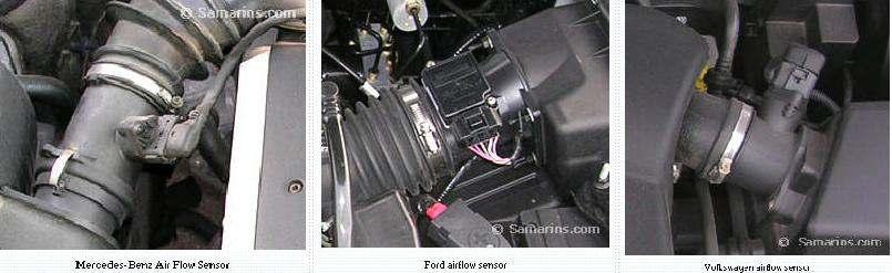
5 Frequently Asked Questions 1. When should I use the Highway and Enhanced setting? Answer: This unit can be switched to the original factory settings by putting the switch in the Original position and is used in this position for cold starts and where conditions such as passing, steep grades or any situation that requires performance is needed. The Enhanced Switch position is used in conjunction with the Highway - City Switch, and the Highway - City Potentiometers which are leaned in to achieve the best mileage in respect to city or highway speeds. Use the Highway setting for speeds above 40 mph. 2. Do the Oxygen Sensors need to be disabled if I use an Enhancer? Answer: I recommend using O2 extenders shown above. 3. Will the Enhancer work on any make and model vehicle with a MAP Sensor? Answer: It will work on MAP Sensors that operate by varying a voltage to the ECU. It will not work if the MAP Sensor is frequency varied only. 4. Will the Enhancer work with a MAF Mass Air Flow Sensor? Answer: If the sensor operates by varying a voltage to the ECM, it should work unless the MAF Sensor is frequency varied only. See Next Page Mass Air Flow Sensor Detail The Air Flow Sensor or Mass Airflow Sensor (MAF) is one of the components of an electronic fuel injection system and is found in many of modern vehicles. The Mass Air Flow sensor is usually installed inside the intake air duct between the air filter and the engine. The Mass Air Flow sensor is used to measure the amount of air entering the engine. This measurement is used by the engine computer or ECM to calculate proper amount of fuel injected into the cylinders in order to provide optimum combustion and low emissions. If your MAF Sensor is voltage varied, incorporate the MAF Enhancer to reduce voltage to the ECM. (See Below.) Note: The information contained in these instructions is for educational purposes only and cannot substitute for the advice of professional mechanic or authorized dealer. Don't attempt to repair your car if you don't have proper knowledge and tools, you can be injured and your vehicle could be damaged. Take your car to a dealer or a repair shop for proper installation. 5
6 6
STAFOR HHO MAF/MAP fully digital and automatic enhancer (corrector). Installation manual. Version
. Installation manual. Version") STAFOR HHO MAF/MAP fully digital and automatic enhancer (corrector). Installation manual. Version 05.14. HHO hydrogen on demand dual fuel systems Introduction The present MAF/MAP Sensor Enhancer is fully
STAFOR HHO MAF/MAP fully digital and automatic enhancer (corrector). Installation manual. Version 05.14. HHO hydrogen on demand dual fuel systems Introduction The present MAF/MAP Sensor Enhancer is fully
The next step is to determine your signal wire from each 02 sensor. This again will be identified in your repair manual wiring diagram.
 Install instructions for True Digital EFIE with MAF/MAP Enhancer. For Narrow Band Oxygen Sensors Only. READ ALL DIRECTIONS BEFORE BEGINNING INSTALLATION It is highly recommended that you purchase a Haynes
Wide Band EFIE Installation Instructions. Locate the wide band oxygen sensor current wire
 Wide Band EFIE Installation Instructions Install your fuel efficiency device The EFIE is not intended to be a fuel saver by itself. You should install a device that is designed to get more energy out of
EFIE Digital Control Panel - Installation Manual
 EFIE Digital Control Panel - Installation Manual HHO Hydrogen on Demand Dual Fuel Generator Systems HHO Plus, Alternative Energies, Ltd Technical Department Travessa das Serras 33, Vieira de Leiria, Portugal
DEFIE (Digital Electronic Fuel Injector Enhancer) Installation & Operating Instructions.
 Installation & Operating Instructions.") DEFIE (Digital Electronic Fuel Injector Enhancer) Installation & Operating Instructions. Please note. The DEFIE is not intended to be a fuel saver by itself. The DEFIE designed to be used only in conjunction
DEFIE (Digital Electronic Fuel Injector Enhancer) Installation & Operating Instructions. Please note. The DEFIE is not intended to be a fuel saver by itself. The DEFIE designed to be used only in conjunction
Electronic Jet Kit Instructions
 MFG P/N FI-1049ST Patent Number: 7,000,599 & 7,124,742 Electronic Jet Kit Instructions Thank you for choosing the Techlusion Electronic Jet Kit, the TFI. This TFI is usable for the following models: Polaris
EFIE Wideband O2 (Electronic Fuel Injector Enhancer) Installation & Operating Instructions.
 Installation & Operating Instructions.") EFIE Wideband O2 (Electronic Fuel Injector Enhancer) Installation & Operating Instructions. The EFIE is not intended to be a fuel saver by itself. The EFIE is designed to be used in conjunction with fuel
EFIE Wideband O2 (Electronic Fuel Injector Enhancer) Installation & Operating Instructions. The EFIE is not intended to be a fuel saver by itself. The EFIE is designed to be used in conjunction with fuel
Install instructions for the New 2016 Tuning 101 AFR Control Center For Wide Band Oxygen Sensors Only.
 Install instructions for the New 2016 Tuning 101 AFR Control Center For Wide Band Oxygen Sensors Only. It is highly recommended that you purchase a Haynes or Chilton s repair manual for your specific vehicle
Install instructions for the EFIE and MAF/MAP Combo For Wide Band Oxygen Sensors Only.
 Install instructions for the EFIE and MAF/MAP Combo For Wide Band Oxygen Sensors Only. It is highly recommended that you purchase a Haynes or Chilton s repair manual for your specific vehicle with a schematic
3. At sea level, the atmosphere exerts psi of pressure on everything.
 41 Chapter Gasoline Injection Fundamentals Name Instructor Date Score Objective: After studying this chapter, you will be able to explain the construction, operation, and classifications of modern gasoline
Fuel control. The fuel injection system tasks. Starting fuel pump (FP)
") 1 Fuel control The fuel injection system tasks - To provide fuel - To distribute the fuel between the cylinders - To provide the correct quantity of fuel Starting fuel pump (FP) The control module (1)
1 Fuel control The fuel injection system tasks - To provide fuel - To distribute the fuel between the cylinders - To provide the correct quantity of fuel Starting fuel pump (FP) The control module (1)
Fuel Metering System Component Description
 1999 Chevrolet/Geo Tahoe - 4WD Fuel Metering System Component Description Purpose The function of the fuel metering system is to deliver the correct amount of fuel to the engine under all operating conditions.
NEW SIMPLIFIED EASY TO FOLLOW AND UNDERSTAND
 NEW SIMPLIFIED EASY TO FOLLOW AND UNDERSTAND Install instructions for the New GM Device #1 EFIE & MAP. For GM Narrow Band Oxygen Sensors Only. If you can read, you can install this device very easily.
Thank you for choosing the Techlusion Electronic Jet Kit, the TFI. The TFI is usable for sequential fuel injection 2 cylinder Suzuki motorcycles **.
 Rev 1.1.1 2055ST TFI TFI Patent Numbers: 7,000,599 & 7,124,742 TFI Instructions Suzuki Thank you for choosing the Techlusion Electronic Jet Kit, the TFI. The TFI is usable for sequential fuel injection
Honda Accord/Prelude
 Honda Accord/Prelude 1984-1995 In Tank Fuel Pumps TEST 1. Turn the ignition OFF. 2. On the Accord, remove the screws securing the underdash fuse box to its mount. Remove the fuel cut off relay from the
Chapter 4 Part D: Fuel and exhaust systems - Magneti Marelli injection
 4D 1 Chapter 4 Part D: Fuel and exhaust systems - Magneti Marelli injection Contents Accelerator cable - removal and..................... 11 Air cleaner element - renewal..............................
Install instructions for the Tuning 101 AFR Control Center 2 For Wide Band Oxygen Sensors Only.
 Install instructions for the Tuning 101 AFR Control Center 2 For Wide Band Oxygen Sensors Only. It is highly recommended that you purchase a Haynes or Chilton s repair manual for your specific vehicle
G - TESTS W/CODES - 2.2L
 G - TESTS W/CODES - 2.2L 1994 Toyota Celica 1994 ENGINE PERFORMANCE Toyota 2.2L Self-Diagnostics Celica INTRODUCTION If no faults were found while performing F - BASIC TESTING, proceed with self-diagnostics.
Troubleshooting A Vintage Distributor Ignition System
 Troubleshooting A Vintage Distributor Ignition System -Henry P. Olsen When the owners of vintage carburetor- and distributor-equipped vehicles see that a shop has a big-box engine analyzer, they believe
Digifant Ignition Basics, Eurovan Or, what to look for if your 5 Cylinder Eurovan won t start due to no spark
 Digifant Ignition Basics, 1992-96 Eurovan Or, what to look for if your 5 Cylinder Eurovan won t start due to no spark The story: In the spring of 2007, I started to have hard starting issues with my 93
Greddy E-manage Installation and Tuning Information
 Greddy E-manage Installation and Tuning Information Overview The Emanage has a lot of functionality considering it is still a piggyback type engine management system and not a full standalone. By itself,
Using the Gratec Gasoline software
 Using the Gratec Gasoline software The Gratec Software is a sophisticated yet user friendly program in which configures the Gratec CNG or LPG system to perform with your vehicle. Software version 2.002
Ignition control. The ignition system tasks. How is the ignition coil charge time and the ignition setting regulated?
 1 Ignition control The ignition system tasks To transform the system voltage (approximately 14 V) to a sufficiently high ignition voltage. In electronic systems this is normally above 30 kv (30 000 V).
Jetting and understanding your CV carburetor
 Jetting and understanding your CV carburetor What do all these pieces do? You may also ask, how or why would I do this to my carb? The goal of this article is to unravel the mystery of carburetor jetting
There are predominantly two reasons for excessive fuelling: increased fuel pressure and extended injector duration. Figure 1.0
 In this tutorial we look at the actuators and components that affect the vehicles exhaust emissions when the electronically controlled fuel injection system is found to be over fuelling. There are predominantly
Tuning 101. How To Gain Success From Your HHO System Part One
 Tuning 101 How To Gain Success From Your HHO System Part One Note: All of the modifications mentioned in this article are now available in a single device called the Tuning 101 AFR Control Center. It will
TUNING Training Course Material 2014 Valid for Diag4Bike V14 only On-line Multimedia User Manual is under preparation.
 TUNING Training Course Material 2014 Valid for Diag4Bike V14 only On-line Multimedia User Manual is under preparation www.diag4bike.eu 1 TUNING STRATEGY Tuning system is based on DIAG4BIKE diagnostics
TOPICS: TIPS FOR DRY CELL INSTALLATION SAFETY PRECAUTIONS
 TOPICS: SAFETY PRECAUTIONS LET'S GET FAMILIAR WITH YOUR NEW DRY FUEL CELL INSTALLATION Connecting The Power Source How To Run Your HHO Gas Into Your Vehicle. How To Use Your Vacuum FINAL SETUP ELECTROLYTE
9. The signal check of Intake Air Temperature Sensor
 9. The signal check of Intake Air Temperature Sensor 1. Troubles 1. The signal line is short to ground (Abnormally low signal voltage : below 0.5 [volt]) Cause of trouble Counter action Engine state Signal
EMISSION SUB SYSTEMS - Closed Loop Feedback Control System
 Emission Control Sub-Systems Closed Loop Feedback Control System The heart of the emissions control system is the closed loop fuel feedback control system. It is responsible for controlling the content
CH. 48 ENGINE MECHANICAL PROBLEMS TEST
 TERRY FOX AUTOMOTIVE CH. 48 ENGINE MECHANICAL PROBLEMS TEST WHEN YOU ARE DONE THIS TEST GUESS WHAT YOU THINK YOU WILL RECEIVE FOR A MARK BELOW. IF YOU ARE WITHIN 2 MARKS YOU WILL RECEIVE 2 BONUS MARKS.
Diagnostic Trouble Code (DTC) memory, checking and erasing
 memory, checking and erasing") Page 1 of 49 01-12 Diagnostic Trouble Code (DTC) memory, checking and erasing Check DTC Memory (function 02) - Connect VAS5051 tester Page 01-7 and select vehicle system "01 - Engine electronics". Engine
Page 1 of 49 01-12 Diagnostic Trouble Code (DTC) memory, checking and erasing Check DTC Memory (function 02) - Connect VAS5051 tester Page 01-7 and select vehicle system "01 - Engine electronics". Engine
UNITED STATES ENVIRONMENTAL PROTECTION AGENCY WASHINGTON, D.C
 UNITED STATES ENVIRONMENTAL PROTECTION AGENCY WASHINGTON, D.C. 20460 OFFICE OF AIR AND RADIATION WHAT YOU SHOULD KNOW ABOUT USING, INSTALLING, OR BUYING AFTERMARKET CATALYTIC CONVERTERS As of January 1,
Technical and Sales Information. Oxygen Sensors
 Oxygen Sensors This booklet is intended for your use as a sales and technical training reference. It answers many questions most commonly asked by: Automotive parts sales professionals Automotive service
Garbage in, garbage out.
 Garbage in, garbage out. Funny, but that old computer adage applies directly to repairing today s cars. Changes in national air quality standards have caused many areas to be declared in nonattainment,
Vacuum Readings for Tuning and Diagnosis
 Vacuum Readings for Tuning and Diagnosis -Henry P. Olsen Once you learn to properly interpret its readings, a vacuum gauge can be one of the most useful tools in your toolbox. 22 FEATURE Some people consider
MT/FZ-09 O2 controller Mod
 kevxtx MT/FZ-09 O2 controller Mod DISCLAIMER: This instruction paper is for informational use. The O2 Controller modification is sold only for race use. The O2 Controller modifies the closed-loop fuel
Tuning 101 Modified for Use With The Tuning 101 Automated Tstat AFR Control Center Updated 12/29/2013
 Tuning 101 Modified for Use With The Tuning 101 Automated Tstat AFR Control Center Updated 12/29/2013 There are many people that are installing HOD systems (Hydrogen On Demand) in their vehicles all over
Module 9 Closed Loop Strategies - Theory
 Module 9 Closed Loop Strategies - Theory Author: Grant Swaim E-mail: sureseal@nr.infi.net URL: www.tech2tech.net Phone: (336) 632-9882 Fax: (336) 632-9688 Postal Address: Tech-2-Tech Website PO Box 18443
Tuning 101 Modified for Use With The Tuning 101 Wideband AFR Control Center
 Tuning 101 Modified for Use With The Tuning 101 Wideband AFR Control Center There are many people that are installing HOD systems (Hydrogen On Demand) in their vehicles all over the world, but not many
Exhaust Gas CO vs A/F Ratio
 Title: Tuning an LPG Engine using 2-gas and 4-gas analyzers CO for Air/Fuel Ratio, and HC for Combustion Efficiency- Comparison to Lambda & Combustion Efficiency Number: 18 File:S:\Bridge_Analyzers\Customer_Service_Documentation\White_Papers\18_CO
DUTCHMAN S STATEMENT CONCERNING THE ORDERING OF HYDRO-ASSIST FUEL CELL SYSTEMS
 DUTCHMAN S STATEMENT CONCERNING THE ORDERING OF HYDRO-ASSIST FUEL CELL SYSTEMS We at Dutchman Enterprises LLC, are the co-developers of this fuel cell technology. It is currently Patent Pending. Our co-developers
Introduction. Open Loop vs. Closed Loop. The Purpose of an O 2 Sensor Clamp
 Introduction This O 2 sensor clamp is designed for use with the Greddy emanage Ultimate engine control system. While these instructions are specific to the Mazda MX-5 Miata, the clamp will work on any
Stop Lamp Switch. STP or BRK. Stop Lamps
 WORKSHEET 2 1 Position/Mode Switches and Circuits (Instructor Copy) Vehicle Year/Prod. Date Engine Transmission Technician Objectives With this worksheet, you will learn to test position/mode circuits
DTC P0171, P0172, P0174, or P0175
 Page 1 of 6 2009 Pontiac G8 G8 Service Manual Document ID: 2076050 DTC P0171, P0172, P0174, or P0175 Diagnostic Instructions Perform the Diagnostic System Check - Vehicle prior to using this diagnostic
4.0L CEC SYSTEM Jeep Cherokee DESCRIPTION OPERATION FUEL CONTROL DATA SENSORS & SWITCHES
 4.0L CEC SYSTEM 1988 Jeep Cherokee 1988 COMPUTERIZED ENGINE Controls ENGINE CONTROL SYSTEM JEEP 4.0L MPFI 6-CYLINDER Cherokee, Comanche & Wagoneer DESCRIPTION The 4.0L engine control system controls engine
Module 12 Throttle Position (TP) Sensor
 Sensor") Module 12 Throttle Position (TP) Sensor Author: Grant Swaim E-mail: sureseal@nr.infi.net URL: www.tech2tech.net Phone: (336) 632-9882 Fax: (336) 632-9688 Postal Address: Tech-2-Tech Website PO Box 18443
Module 12 Throttle Position (TP) Sensor Author: Grant Swaim E-mail: sureseal@nr.infi.net URL: www.tech2tech.net Phone: (336) 632-9882 Fax: (336) 632-9688 Postal Address: Tech-2-Tech Website PO Box 18443
Alternative Fuel Engine Control Unit
 1999 Chevrolet/Geo Cavalier (CNG) Alternative Fuel Engine Control Unit Table 1: AF ECU Function Parameters The (AF ECU) controls alternative fuel engine operation. The control unit monitors various engine
EMISSION CONTROL VISUAL INSPECTION PROCEDURES
 EMISSION CONTROL VISUAL INSPECTION PROCEDURES 1992 Infiniti G20 1983-98 GENERAL INFORMATION Emission Control Visual Inspection Procedures All Models * PLEASE READ THIS FIRST * This article is provided
TOURING Models
 P/N FI-1252HPST Patent Numbers: 7,000,599 & 7,124,742 Electronic Jet Kit Instructions Thank you for choosing the Techlusion Electronic Jet Kit, the TFI. This TFI model is ONLY usable for the following
Direct Link Basic Tuning Guide (Delphi)
") Direct Link Basic Tuning Guide (Delphi) This Guide is intended to answer basic Direct Link tuning questions and to act as a Quick Start Guide. It is not intended to be the Gospel on the tuning process
Direct Link Basic Tuning Guide (Delphi) This Guide is intended to answer basic Direct Link tuning questions and to act as a Quick Start Guide. It is not intended to be the Gospel on the tuning process
Everything Leading Up to Nuclear Cars. next 150 years is to have a car that runs on the splitting of atoms. This will be a clean and
 Ethan Brunet-Bailey Everything Leading Up to Nuclear Cars Engineering is why we have cars, electronics, and everything around us. The car that we have in 2016-2017 runs off of fossil fuels and some are
1 of 2 9/4/ :27 AM
 Ford Mustang IAC IAB - Solving your idle problems http://www.muscularmustangs.com/iac.php 1 of 2 9/4/2010 10:27 AM Solving idle problems part 1 - Cleaning your IAC Does your idle rise and fall over and
GASOLINE DIRECT INJECTION IN SI ENGINES B. PAVAN VISWANADH P. ASHOK KUMAR. Mobile No : Mobile No:
 GASOLINE DIRECT INJECTION IN SI ENGINES SUBMIT TED BY B. PAVAN VISWANADH P. ASHOK KUMAR Y06ME011, III/IV B. Tech Y06ME003, III/IV B. Tech Pavan.visu@gmail.com ashok.me003@gmail.com Mobile No :9291323516
Helicopter Engine Tuning. 2 needle engines. Tuning the Mixture Control Screw. Pinch Test.
 Helicopter Engine Tuning Tuning a helicopter engine is difficult because you cannot change settings on a running engine. With this document I try to give you generic tips to tune your engine. Important:
Error codes Diagnostic plug Read-out Reset Signal Error codes
 Error codes Diagnostic plug Diagnostic plug: 1 = Datalink LED tester (FEN) 3 = activation error codes (TEN) 4 = positive battery terminal (+B) 5 = ground Read-out -Connect LED tester to positive battery
OMEM200 Tuning Manual 3v Series ECU. Tuning Manual OMEM200.
 200 Series ECU Tuning Manual OMEM200 www.omextechnology.com 0 1 Introduction... 3 1.1 What this manual covers... 3 1.2 Notation Used in This Manual... 3 2 Software... 4 3 Sensor Setup... 5 3.1 Throttle
2002 ENGINE PERFORMANCE. Self-Diagnostics - RAV4. Before performing testing procedures, check for any related Technical Service Bulletins (TSBs).
.") 2002 ENGINE PERFORMANCE Self-Diagnostics - RAV4 INTRODUCTION NOTE: Before performing testing procedures, check for any related Technical Service Bulletins (TSBs). To properly diagnosis and repair this
2002 ENGINE PERFORMANCE Self-Diagnostics - RAV4 INTRODUCTION NOTE: Before performing testing procedures, check for any related Technical Service Bulletins (TSBs). To properly diagnosis and repair this
MAF Translator / Translator Plus Installation/Description (Version 5.x)
") Installation The MAF Translator and Translator Plus are easy to install. The MAF Translator is a simple plug-in, while the Translator Plus requires connection of the Spark signals into the vehicle's electrical
Installation The MAF Translator and Translator Plus are easy to install. The MAF Translator is a simple plug-in, while the Translator Plus requires connection of the Spark signals into the vehicle's electrical
THE IDIOT S GUIDE TO TUNING SU CARBURETTERS
 THE IDIOT S GUIDE TO TUNING SU CARBURETTERS There are four distinct phases to tuning SU carburetters (carbies). The first is to set the fuel level in the float bowl, the second is to centre the needle
The Bosch LH 2.4 Jetronic System is used on the models (and later non-turbo/non-odbii models)
") The Bosch LH 2.4 Jetronic System is used on the 89-93 models (and later non-turbo/non-odbii models) 1-1-1 No faults. 1-1-2 Control unit fault. 1-1-3 Fuel injectors - Injector cable break or blocked injector;
The Bosch LH 2.4 Jetronic System is used on the 89-93 models (and later non-turbo/non-odbii models) 1-1-1 No faults. 1-1-2 Control unit fault. 1-1-3 Fuel injectors - Injector cable break or blocked injector;
RAFIG IDLE TUNING PROCESS
 RAFIG IDLE TUNING PROCESS I decided to PDF this process and bring everything I found into one document as when I went to idle tune it was in bits and pieces so I have gathered SSpdmon s info and put it
A short explanation of the modifications made in a poor quality ECU remap
 HDI-Tuning Limited A short explanation of the modifications made in a poor quality ECU remap Steven Lewis 12 Introduction This document has been written to educate those planning on using a poor quality
1998 ENGINE PERFORMANCE. General Motors Corp. - Basic Diagnostic Procedures - 5.7L
 INTRODUCTION 1998 ENGINE PERFORMANCE General Motors Corp. - Basic Diagnostic Procedures - 5.7L The following diagnostic steps will help prevent overlooking a simple problem. This is also where to begin
This is what we are trying to create in the steps below
 You will need: (1) Some 3/4 aluminium or steel flat bar (+/- 1 foot) (2) About 12 of 3 Aluminium or steel tubing. (2) Piece of 3X3 silicone hose and 2 hose clamps (3) 1 K&N (or similar) high flow filter
FUEL INJECTION SYSTEM - MULTI-POINT
 FUEL INJECTION SYSTEM - MULTI-POINT 1988 Jeep Cherokee 1988 Electronic Fuel Injection JEEP MULTI-POINT 4.0L Cherokee, Comanche, Wagoneer DESCRIPTION The Multi-Point Electronic Fuel Injection (EFI) system
Oxygen sensor control,
 Page 1 of 37 24-71 Oxygen sensor control, checking Oxygen sensor and oxygen sensor control before catalytic converter, checking Special tools and equipment - or VAG1526A VAG1594A VAG1598/31 VAS5051 with
Throttle Body Instruction Sheet
 Throttle Body Instruction Sheet Thank you for purchasing our modified O.E.M. or new Billet throttle body. They have proven to give considerable power increases when properly adjusted and used alone on
Powertrain DTC Summaries EOBD
 Powertrain DTC Summaries Quick Reference Diagnostic Guide Jaguar X-TYPE 2.0 L 2002.25 Model Year Refer to page 2 for important information regarding the use of Powertrain DTC Summaries. Jaguar X-TYPE 2.0
The All-New BIG97 Tri-Power. In Detail.
 The All-New BIG97 Tri-Power. In Detail. The all-new Stromberg BIG97. On the outside, it s Genuine 97 all the way. But on the inside, we re talking 250cfm, new improved fuel circuits, ported distributor
A Simple View of Fuel Injection
 A Simple View of Fuel Injection Your engine is an air pump, the more air you pump through it, the more power you make. Figure 1 Any internal combustion engine will flow air at a rate determined by many
Powertrain DTC Summaries OBD II
 Powertrain DTC Summaries Quick Reference Diagnostic Guide Jaguar X-TYPE 2.5L and 3.0L 2002 Model Year Revised January, 2002: P0706, P0731, P0732, P0733, P0734, P0735, P0740, P1780 POSSIBLE CAUSES Revised
SHOEBOX ELECTRONIX 8385V ECU MONITOR
 SHOEBOX ELECTRONIX 8385V ECU MONITOR USER MANUAL & TROUBLESHOOTING GUIDE Sept 28, 2008 10/5/2008 1 Table of Contents Your Vanagon & it s ECU... 3 Vanagon ECU & System Components... 4 ECU Input Signals...
Learning Guide EMISSION SPECIALIST 5 GAS ANALYSIS COURSE NUMBER: E001-01
 Learning Guide EMISSION SPECIALIST 5 GAS ANALYSIS COURSE NUMBER: E001-01 Notice Due to the wide range of vehicles makes and models, the information given during the class will be general in nature and
HOWELL INSTALLATION MANUAL. Tuned Port Or LT-1 Fuel Injection Harness ( )
") HOWELL ENGINE DEVELOPMENTS, INC. FUEL INJECTION APPLICATIONS INSTALLATION MANUAL Tuned Port Or LT-1 Fuel Injection Harness (1985-1992) Howell Engine Developments, Inc. 6201 Industrial Way Marine City,
HOWELL ENGINE DEVELOPMENTS, INC. FUEL INJECTION APPLICATIONS INSTALLATION MANUAL Tuned Port Or LT-1 Fuel Injection Harness (1985-1992) Howell Engine Developments, Inc. 6201 Industrial Way Marine City,
Intake Kit Supplement for CRV and Pathfinder
 Intake Kit Supplement for CRV and Pathfinder This guide will briefly outline how to install the intake kits for the Honda CRV and Nissan Pathfinder. This is a pretty basic job, but for the average person
Remote Start System OWNER S MANUAL. Mazda CX-9
 Remote Start System OWNER S MANUAL Mazda CX-9 Introduction Congratulations on your purchase of a Mazda Remote Start System specifically engineered for Mazda featuring PowerCode Technology TM. This easy-to-use
Lambda Control Fuel Adaptation and Fuel Trim
 Lambda Control Fuel Adaptation and Fuel Trim Q: What is Lambda and Lambda Control? A: In the case of a gasoline engine, the optimal mixture of air to fuel for complete combustion is a ratio of 14.7 parts
WEBER CARBURETOR TROUBLESHOOTING GUIDE
 This guide is to help pinpoint problems by diagnosing engine symptoms associated with specific vehicle operating conditions. The chart will guide you step by step to help correct these problems. For successful
I N S T A L L A T I O N I N S T R U C T I O N S TIMING COMMANDER Interface Gauge Ver 7
 I N S T A L L A T I O N I N S T R U C T I O N S 103033 TIMING COMMANDER Interface Gauge Ver 7 This product is designed to interface with the airtemp (IAT) sensor in your vehicle AND your tuner software
Innovative Racing Electronics
 MPS Fast FI Mixture Control Installation Instructions The MPS Fast FI Mixture Control P/N 1-0337 is a simple means to adjust the fuel curves on your fuel-injected motorcycle. This allows for tuning after
VS403 INSTRUCTIONS FOR: VACUUM AND PRESSURE TEST / BRAKE BLEEDING UNIT MODEL: SAFETY INSTRUCTIONS INTRODUCTION & CONTENTS. fig.1
 INSTRUCTIONS FOR: VACUUM AND PRESSURE TEST / BRAKE BLEEDING UNIT MODEL: VS403 Thank you for purchasing a Sealey product. Manufactured to a high standard this product will, if used according to these instructions
ACCEL Distributor Model #A557
 FORM 1627 REV1 INSTALLATION INSTRUCTIONS ACCEL Distributor Model #A557 CAUTION: CAREFULLY READ INSTRUCTIONS BEFORE PROCEEDING. NOT LEGAL FOR USE OR SALE ON POLLUTION CONTROLLED VECHICLES OVERVIEW ACCEL
Common Terms Selecting a Turbocharger Compressor... 4
 TURBOCHARGERS Common Terms... 2 Adiabatic Efficiency... 2 Pressure Ratio... 2 Density Ratio... 2 Turbine... 2 A/R Ratio... 2 Charge-Air-Cooler... 2 Boost... 3 Waste Gate... 3 Turbo Lag... 3 Boost Threshold...
WARNING!!! DO NOT OPERATE WHILE DRVING!! INSTALLATION & USER GUIDE
 V-FORCE Plus Engineered For Power! WARNING!!! DO NOT OPERATE WHILE DRVING!! INSTALLATION & USER GUIDE Installation Instructions JET V-Force 1. Mounting the V-Force Using the supplied Velcro, Suction Cups
Truck and Transport IP Red Seal Practice Exam PRACTICE EXAM 4
 Truck and Transport IP Red Seal Practice Exam PRACTICE EXAM 4 1. Which of these sensors directly measures engine load? a. Manifold absolute pressure sensor. b. Coolant sensor (ECT). c. Vehicle speed sensor.
2003 Audi A4 testing
 2003 Audi A4 testing An Audi A4 equipped with a 1.8L AMB turbocharged engine was in for service. The owner had just received it back from his kid, indicating it was neglected, having few if any oil changes
Module 11 Thermistor Inputs
 Module 11 Thermistor Inputs Author: Grant Swaim E-mail: sureseal@nr.infi.net URL: www.tech2tech.net Phone: (336) 632-9882 Fax: (336) 632-9688 Postal Address: Tech-2-Tech Website PO Box 18443 Greensboro,
Installation Directions for FINGER STICK and Blocker Plate
 Installation Directions for FINGER STICK and Blocker Plate What is a Finger Stick? A Finger Stick is a simple circuit that modifies the MAF signal on LLY and LBZ engines (not LB7 engines) to expected levels
Catalytic Converter Testing
 Catalytic Converter Testing The first catalytic converter was created before the use of onboard computer systems its job was to oxidize HC and CO into CO2 and H2O. The term oxidizes means to add O2 to
Auto Diagnosis Test #7 Review
 Auto Diagnosis Test #7 Review Your own hand written notes may be used for the 1 st 10 minutes of the test Based on Chapters 25, 26, 32, 33, 34 and Lab Demonstrations Auto Diagnosis Test #7 Review Your
Corrado Club of Canada. VR6 Engine FAQ. By: Dennis
 Corrado Club of Canada VR6 Engine FAQ By: Dennis I thought I would snap a few pics of the engine compartment on my 1994 VR6 Corrado. First, this is the updated engine management system so it does have
Through Preventative Maintenance
 Through Preventative Maintenance The recommendations contained herein are provided at your own risk. Track use, whether you are racing or not, requires that you maintain your car more frequently, like
Simple DIY Rev Switch Switch on or off anything at an adjustable engine rpm!
 Simple DIY Rev Switch Switch on or off anything at an adjustable engine rpm! By Julian Edgar So what about making it a general-purpose rev switch, able to switch pretty well any electrical loads? That
Technical Support Note
 Title: Measuring Emissions from Diesel-Fueled Equipment TSN Number: 09 File:S:\Bridge_Analyzers\Customer_Service_Documentation\Technical_Support_Notes\ 09_Measuring_Emissions_from_Diesel_Fuel_Equipment.docx
Chrysler Electronic Ignition System
 1 of 11 1/6/2010 11:02 PM Chrysler Electronic Ignition System Classic Winnebago's Post by: DaveVA78Chieftain on August 13, 2009, 10:15 PM Components The Chrysler Electronic Ignition System consists of
Powertrain DTC Summaries EOBD
 Powertrain DTC Summaries Quick Reference Diagnostic Guide Jaguar S-TYPE V6, V8 N/A and V8 SC 2002.5 Model Year Refer to pages 2 9 for important information regarding the use of Powertrain DTC Summaries.
ENGINE AND EMISSION CONTROL
 17-1 ENGINE AND EMISSION CONTROL CONTENTS ENGINE CONTROL SYSTEM........ 3 SERVICE SPECIFICATION............... 3 ON-VEHICLE SERVICE.................. 3 Accelerator Cable Check and Adjustment... 3 ACCELERATOR
STAFOR HHO lambda sensor extender. Installation manual. HHO hydrogen on demand dual fuel systems. Ecologically clean lowers CO and CO2 emissions
 STAFOR HHO lambda sensor extender. Installation manual. HHO hydrogen on demand dual fuel systems Installing of lamda sensor extender Basic information Also called oxygen sensors as it measure the amount
DFS Dynamic Fuel Systems Inc.
 DFS Dynamic Fuel Systems Inc. Dynami c Fuel System s Inc. Diesel Magnum US PAT# 7100582 Installation Manual Diesel Magnum US PAT# 7100582 Installation Manual Ver 52.1 www.dynamicfs.com www.fireemup.com