UAV engine EFI installation manual
|
|
|
- Edmund Tucker
- 6 years ago
- Views:
Transcription
1 UAV engine EFI installation manual -DLE120 engine Installation Manual V1.7 COPY RIGHTS ECOTRONS LLC ALL RIGHTS RESERVED 1
2 Note: If you are not sure about any specific details, please contact us at Index Page Revision Date Note 1 First Edition V1.1 2 Second Edition V1.2 3 Third Edition V1.3 4 Fourth Edition V1.4 5 Fifth Edition V1.5 6 Sixth Edition V1.6 7 Seventh Edition V1.7 2
3 Content Introduction... 5 Chapter 1 EFI installation Remove the stock carburetor and install the throttle body Install the fuel supply system Install the cylinder head temperature sensor (CHT) Install the intake air temperature sensor (IAT) Install the ignition system Connect the ECU harness to the stock CDI and pickup sensor Use Ecotrons CDI for ignition control Servo motor installation Parameters of servo motor Installation of servo motor The connection of TPS signal Control Servo motor Install the fuel injector and connect the connector Connect the harness to 12V battery Mount the ECU Mount the Harness Optional prime switch function Chapter 2 ALM-ECU integration for tuning
4 2.1 Install the wideband O2 sensor Connect the ALM to ECU Connect the ALM to ECU via Performance switch Connect ALM-CAN to ECU via CAN bus Chapter 3 Broadcast protocol ECU broadcast data list on RS ECU broadcast data list on CAN bus The CAN Baud rate setting of ECU Can bus broadcast Chapter 4 Communication Settings COM communication mode USB communication mode CAN communication mode Ethernet communication mode Chapter 5 Initial test after the installation Chapter 6 How do we know the fuel injector flow rate Chapter 7 UAV EFI Maintenance
5 Introduction UAV EFI for DLE engine is an Electronic Fuel Injection conversion kit for the UAV engine. It is a bolt-on EFI kit to a lot of small engines, for example, DLE-20, DLE-40, DLE-60, DLE-120, DLE-170 etc. We can supply the suitable EFI kit for most of UAV engines. The displacement of the engines can be in the range of 20cc to 300cc, and even larger engines. This UAV EFI kit has below features: Electronic fuel injection (EFI) Quick engine start even at cold temperatures More power and torque than the carbureted version High fuel efficiency and low carbon emissions OBD - on board diagnosis Performance tuning for advanced users. Altitude compensations Transient fuel compensations Servo motor control (optional) Ignition control (optional) Parts: 1. ECU 2. Harness (including the connectors) 3. Throttle Body Throttle body Servo motor(included) TPS sensor(optional) Fuel injector (mounted on the throttle body) 4. Fuel pump assembly Rotary fuel pump with pressure regulator (outside of the tank, 25L/h)) 5. Baro sensor (integrated in ECU) 6. Engine temperature sensor 7. Intake air temperature sensor 8. Ecotrons CDI - ECU controlled (optional, you can use your own CDI). 5


6 9. Serial communication cable (to a computer) 10. USB adaptor - included 11. CD for tuning software (downloadable from our website) UAV engine EFI installation manual-dle120-v1.7 Note: The kit requires a 12V battery by default. 37-pin ECU and Harness Fuel pump group 6


7 Throttle body with TPS and Servo motor Throttle body with Servo motor Engine temperature and intake air temperature Ecotrons CDI Unit 7

8 Chapter 1 EFI installation 1.1 Remove the stock carburetor and install the throttle body Note: the stock DLE 120 carburetor is about 22mm diameter outlet. The Ecotrons throttle body is also 22mm diameter. So it is a bolt-on replacement. Note: Ecotrons Small throttle body is designed to replace the stock carburetor and has the same or similar spacing as the carburetor, so that you can bolt on the throttle body. Ecotrons throttle body is designed to mount the Futaba servo motor easily. So the complete throttle body / servo is compact and light. Ecotrons Small throttle body is designed to mount Ecotrons small engine injectors. It comes with the injector fittings and thread-on fuel lines. The injector flow rates: 30g/min, 38, 60, 80, 128, 190, 248g/min etc. 8

9 And we also have 14mm, 18mm, 22mm, 28mm throttle body for UAV engines, so we can provide the UAV EFI kit for different engines with different displacement. Some engines, you can use the throttle body to replace the carburetor completely, and for some engines, you need make the adapter to bolt on the throttle body. Note: Some custom system comes with the throttle position sensor, so if you want to use the throttle position sensor, you also need to install the TPS sensor on the throttle body. Note:Because the stock blot is too long, so you cannot use them to bolt on the throttle body directly. You may need to add a suitable washer/ nut, as shown in this picture. Or cut the stock blot short. 9


10 Please don t remove the Limit screw from throttle body. 10

11 1.2 Install the fuel supply system UAV engine EFI installation manual-dle120-v1.7 Customers have to find a good location to install the fuel pump. By default, the fuel pump should be lower than the fuel tank. The fuel feed inlet in the tank should be submerged in the fuel all the time. There should be an inline fuel filter, which is not included in the kits. You need to find one suitable fuel filter to be installed. Note: The EFI has a fuel pressure regulator which requires a fuel return line back to the fuel tank. 11


12 Note: The fuel pump bracket is optional, and the fuel pump bracket is not included in the default UAV EFI kits. The fuel pump is a rotor type, has 25L/h flow rate. It has only limited sucking power. If there are too many air bubbles in the fuel lines, the pump will not work. Connect the connector to the fuel pump 12

13 1.3 Install the cylinder head temperature sensor (CHT) The CHT sensor must be installed at the cylinder head, closed to spark plug. If you can place it under the spark plug, it is also OK. Note: The best choice is that CHT s wiring is on the lee side. Do strain it as far as possible to prevent the shaking caused by the wind or gravitation when you fix the wire of CHT. Besides, the wire does not be bended repeatedly when CHT is installed. 1.4 Install the intake air temperature sensor (IAT) Please install the intake air temperature sensor in the air box, or put the IAT in the air if there is no air box. And make sure there is no twisting stress on the IAT wire after finish IAT installation. 13

14 1.5 Install the ignition system For DLE series engine, you can choose to keep the stock ignition system, or use Ecotrons CDI unit to make ECU to control ignition system. If you want the ECU to control the CDI ignition timing, and the Ecotrons CDI will be included in the kit, please read the chapter Connect the ECU harness to the stock CDI and pickup sensor For DLE series engines, if you choose that the EFI only controls the fuel injection, and keep the stock CDI, you only need to tap the stock pick-up signal wire and stock CDI to ECU harness. You can find the connector adaptor which was provided from us in the kits. There are three labels, To Hall sensor, To CDI, To harness Hall on connector adaptor. The below picture is the connections of connector adapter, harness, and stock pick-up sensor, stock CDI. 14

15 The connector adaptor labeled To Hall sensor connects to stock hall sensor. The connector adaptor labeled To CDI connects to stock CDI. The connector adaptor labeled To harness Hall connects to the connector labelled HALL SENSOR from ECU harness. Note: You don t need to connect the connector labelled CDI Power CDI Ctrl of ECU harness Use Ecotrons CDI for ignition control You can use ECU to control ignition system with Ecotrons CDI and keep the stock pickup sensor Connect the ECU harness to the CDI Please connect the CDI connector from ECU harness to the Ecotrons CDI unit. 15

16 Ecotrons CDI Unit Connect the CDI Power from ECU harness to the red connector of Ecotrons CDI. Connect the CDI Ctrl from ECU harness to the black connector of Ecotrons CDI. The connector which is labeled Tachometer can be connected to your own Tachometer. 16
 CDI Ctrl: ECU outputs to control Ecotrons CDI.")
17 Note: 1) CDI Power: it gives Ecotrons CDI power. 2) CDI Ctrl: ECU outputs to control Ecotrons CDI. 3) Do NOT plug the connectors in the wrong direction. 17

18 Connect the Hall-Sensor connector to the stock Hall sensor. 1.6 Servo motor installation Parameters of servo motor The servo motor is installed on the throttle body for an UAV EFI system by default. It is to open and close the throttle valve, as the throttle actuator. We use the Futaba S3016 servo motor in our EFI system. 18
 width: 0.63 in(16.0 mm) height:1.21 in(30.7mm) There are three wires in servo. The black is ground, the white is the control signal line, and the red is the power line, which is 5V.")
19 Futaba servo S3016: Type Analog Servo Torque 4.8V: 47.0 oz-in(3.38kg-cm) 6.0V: 58.0oz-in(4.18kg-cm) Speed 4.8V: 0.25 sec/60 6.0V: 0.20 sec/60 Weight 1.20 oz(34.0 g) Size length: 1.22 in(31.0 mm) width: 0.63 in(16.0 mm) height:1.21 in(30.7mm) There are three wires in servo. The black is ground, the white is the control signal line, and the red is the power line, which is 5V. 19
20 1.6.2 Installation of servo motor Note: Usually we install the Servo motor on the throttle body, you don t need re-install it. If you need install the servo motor, please see the following information as reference. The Servo is controlled by the auto-pilot of the UAV, via a PWM signal. The PWM duty cycle is inversely proportional to the throttle. What s the best range of rotation angle when the servo motor is installed? 20
21 Note: You would assume the total rotation angle of a servo motor is degrees; but actually, the servo rotation angle is about 90 degrees when used to control the throttle. 21

22 As shown in the above picture, the servo angular positions of -45 degree to 45 degree are corresponding to throttle position of 0 to 180 degrees. Example of installation: We use the Futaba S3016 servo motor in our EFI system. The simplest method for servo motor installation: By default, the servo rotation travelling is about 180 degrees. But we are going to only use half of that travelling range. Try to manually rotate the servo arm to find the upper and lower mechanical stop positions. It is about 180 degree travelling range. Note: Don t rotate more than 180 degrees with too much force; otherwise it could damage the servo motor. (The RED circle in the picture is the reference point). 0 position of the servo arm. 22
23 About 180 degree position of the servo arm: 1. Make sure the servo can rotate freely between degrees, then position the reference point (The RED circle) in the middle of the 180 degree range. That means, from that position, it can go 90 degrees either way. This position is going to be the 0 degree position. 23

24 2. Install the servo on the throttle body. Before you connect the servo and the throttle, open the throttle valve about 40 degree, where the throttle opening is about 50%. Note: the total throttle valve turning angle might be only 80 degrees. Keep the throttle about 50% opening, and connect the throttle valve arm to the servo arm with the servo link rod. By doing this, the servo 0 degree reference position is corresponding to the 50% of throttle opening. The concept of this is because the servo will be moved both ways, from the 0 degree position. 24

25 3. After linking the servo to the throttle valve, try to move the servo both ways, and make sure the throttle valve is opening and closing. You shall notice that the servo is about -40 degrees when throttle valve is fully closed, and it is about 40 degrees when the throttle valve is fully opened. This will ensure that the servo will move within its reasonable range when the throttle is changing between 0-100%. Throttle Valve is fully closed 25


26 Throttle Valve is fully opened Note: the throttle idle position can be adjusted by the mechanical idle stop. Finally, fix and tighten everything. 26

27 Warning: For the servo installation, you have to make sure the throttle and servo are both synchronous with one another. When the servo arm moves, the throttle valve arm also should moves. If the servo arm moves, but the throttle valve arm doesn t move, the throttle valve will not be opened; this will not allow the engine to run well when you add the throttle via your auto-pilot of the UAV. 1.7 The connection of TPS signal For some large displacement engines, larger than 60cc, we provide the TPS sensor. So you need to connect the TPS connector to the TPS sensor which is mounted on the throttle body. 1.8 Control Servo motor Note: It will be the custom UAV engine EFI kit If you want our ECU to control servo motor, please contact us to get the custom harness. 27

28 The auto-pilot from customer must send the command to ECU. 1) The default duty cycle of servo control PWM signal is 20ms. 2) The default pulse width is ms, but if the pulse is 2.5ms, the servo will rotate in 360 degrees. So the correct range is ms to protect the servo motor. 3) The rotation angle is about 180 degrees, so please don t rotate the servo more than 180 degrees. 4) Do not incorrectly connect the wires of the servo motor. 1.9 Install the fuel injector and connect the connector 1.10 Connect the harness to 12V battery The 12V battery is needed in the UAV EFI kit. You can choose the 12V lithium battery is light weight, Small volume, good performance. 28

29 Note: the red is to the positive of battery; the black is to the negative of battery. There is one manual switch on the power wire; you can use this switch to power on EFI, or power off. Note: connect the negative of battery to the engine block. All ground wires should be common. 29


30 Note: The black wire goes to negative of battery Mount the ECU Find a safe place to mount the ECU, avoid the severe vibration and severe hot conditions. Do not expose it to water / fluids. This ECU is NOT water proof. Please notice to tighten the screw of harness after ECU connects harness. 30

31 Parameters of ECU Aluminum case, light weight: 120 gram total; Mini size: 78x64x20mm dimensions; mini-d connector (37 pin); built-in baro sensor, automatic altitude compensation; controlling 1 or 2 cylinder engines, both fuel injection and ignition controls; CAN bus capable; Pictures of ECU 31

 9 VCC Yellow Power of Hall sensor 10 CANL Green")
32 Definition of pins: Number Define Color instructions 1 INJ1 White Fuel injector # 1 low side driver output 2 KEYSW Blue Fuel injector # 1 power output 3 GND Black Power ground 4 GND Black Power ground 5 ROUT White Relay low side driver output 6 KEYSW Blue Relay power output 7 GND Green CKP(pick-up) sensor ground 8 CKP White Crank Position sensor input (Pickup) 9 VCC Yellow Power of Hall sensor 10 CANL Green CANL 32
33 11 CANH Yellow CANH 12 MAP White Intake manifold pressure sensor (Optional) 13 RXD White Goes to RXD of RS TXD Yellow Goes to TXD of RS GND Green RS232 ground 16 PWMIN White Servo motor PWM input 17 PWMOUT White Servo motor control PWM output (Optional) 18 GND Green Servo motor ground 19 VCCM Yellow Power of servo motor (Optional) 20 NULL NULL GNDP Blue Power ground 23 GNDP Red Power ground 24 KEYSW Blue Power of Mil-Lamp 25 Mil-lamp White Mil-Lamp 26 12V+ Blue ECU power input 27 12V+ White ECU power input 28 CHT White Cylinder head temp sensor input 29 GND Green CHT ground 30 GND Green IAT ground 31 IAT White Intake air temp sensor input 32 VCC Yellow +5V Power of Throttle position sensor 33 TPS White Throttle position sensor signal 34 GND Green Ground of throttle position sensor 35 Per_SW White Performance switch 36 GND Green Ground 37 CDI-PG White Control signal of CDI 1.12 Mount the Harness Please find the suitable place to mount the harness. 33

34 The Wire Length: From ECU main connector From the main Connector Length 12V- 500mm 12V+ 500mm Injector TPS CHT IAT Hall sensor Servo Tps CDI Control CDI Power MIL- Lamp RS mm 500mm 500mm 500mm 500mm 500mm 500mm 500mm 200mm 200mm 34

35 Perf-SW CAN 200mm 200mm From Relay 12V+ 500mm 12V- 500mm Fuel Pump 500mm Notice, the Length does not include the length of connector, and it is only the wire length. Usually, the error range is 10mm Optional prime switch function There is a prime switch on the EFI harness. The function is to manually trigger the EFI to inject a little fuel before you start the engine by hand. When engine is ready to start, you press it to the I position, it will inject a little starting fuel. It only injects one time even if you leave it at I position. If you want to inject more fuel, you can cycle this switch, meaning back O position, and then press it again to I position. 35
, you need connect the linear analog output of wideband controller to the ECU harness, 36")
36 Chapter 2 ALM-ECU integration for tuning 2.1 Install the wideband O2 sensor You need drill the hole and weld the bung in the exhaust and to install the O2 sensor. 2.2 Connect the ALM to ECU Connect the ALM to ECU via Performance switch ECU can read the Lambda (AFR) from the wideband controller with LSU4.9 sensor (ALM), you need connect the linear analog output of wideband controller to the ECU harness, 36

37 then ECU can read the real-time lambda, and you can use the lambda to tune the fuel mapping of EFI. We use the "Perf-SW", performance switch, wire to connect the ALM input. Most of EFI has this Perf-SW switch, you need tap the linear output of wideband controller to the wires of performance switch. Please connect it by using following pictures. Connection Connect the ANOUT to the white wire of performance switch Connect the GND to the green wire of performance switch. Warning: You need set the performance switch be O side, if not; it will not read the real-time lambda correctly Please do a modification to match the ALM in CAL file. 37

38 Please set the variable: CV_SSWO2 = Connect ALM-CAN to ECU via CAN bus If you order the ALM-CAN units from Ecotrons, which can be connected to ECU directly. ECU can receive the data from ALM-CAN by broadcasting and analyze the data to get the value about Lambda, AFR and O2%. You need to modify the following calibration variable to match the ALM-CAN in CAL file. Please set the variable: CV_SSWO2 = 3. 38
39 Chapter 3 Broadcast protocol 3.1 ECU broadcast data list on RS232 You can read some parameters of engine from the RS232 serial cable by using your equipment. So we provide the protocol to you for using this function. Variables: RPM, MAP, TPS, ECT, IAT, O2S, SPARK, FUELPW1, FUELPW1, UbAdc. Note: Enable the broadcast data function; please tune the CV_APP to be 128, then burn to ECU. Calibration: CV_APP=128 If you don t have this variable, please connect us. The data format is hex, the baud rate is , no parity bit, 8 data bits, 1 stop bit, time interval 100ms. Please go to our website to download the document: Download the Ecotrons Broadcast data list. See the mark of the Ecotrons Broadcast data list as shown below. 39

40 3.2 ECU broadcast data list on CAN bus The CAN Baud rate setting of ECU Our ECU and tuning software (EcoCAL) support the CAN communication, you can change the baud rate by yourself. Note: There should be a 120 ohm resistor between the CAN wires, and our ECU doesn t have the 120 ohm termination resistor, so you need add it by yourself in the CAN connector, see below picture, 40

41 The calibration variable is VAL_CAN0_BaudRate, you can find this variable in Advanced. The default is 250k, so VAL_CAN0_BaudRate = 4. VAL_CAN0_BaudRate /* CAN bus baud rate k, k, k, k, 7--50k, 8--20k, 9--10k, 10--5k */ Can bus broadcast Please go to our website: Download the Ecotrons UAVCAN Protocol. See the mark of the Ecotrons UAVCAN Protocol as shown below. 41
42 42

43 Chapter 4 Communication Settings How to install the provided EcoCAL software to your computer? For details on how to use EcoCAL software, please refer to the EcoCAL Manual, downloadable here: Run EcoCAL, you will see below windows: Connect ECU to laptop: 43


44 Read DTC: Go to Menu à Diagnostics ->ECU Diagnostics 44

45 Click "Read DTC": Click "Clear DTC": 45

46 You should select the communication mode first based on which way you use COM, CAN or Ethernet. In default, we provide the COM RS232 cable and USB adapter, so you can use the COM or USB for communication. Go to menu->settings->communication Settings: 46
. This configuration is consistent with most of the computers. 4.")
. Select COM and set the COM port, the default COM port is COM1.")
47 Note: By default, EcoCAL uses USB communication mode (Note: insert the Ecotrons USB adaptor into the laptop first for USB mode). This configuration is consistent with most of the computers. 4.1 COM communication mode If the user is using the COM mode (Note: for this mode, your laptop need to have a built-in COM port). Select COM and set the COM port, the default COM port is COM1. 47

48 Built-in COM port (9-pin) RS232 cable The default baud rate is , which the fastest of the serial comm. rate of the PC. It is not supposed to change. 4.2 USB communication mode Most new computers do NOT have a built-in COM port any more. You should insert the USB adaptor (Ecotrons USB Adaptor) to the laptop, and then select the USB in the communication settings window of EcoCAL. 48

49 Note: We do not support the 3rd party USB-RS232 adapters, even though they might work sometime. The problem is that those consumer electronics rated USB adapters only works in a noise-free environments. This means, once the engine is running, it generates a lot of electronic magnetic noises. And those USB adapters, though looking pretty, will not stay working when you are driving. That's why we developed our own. Note: Make sure the connection between laptop and USB adaptor (Serial communication cable) is FULLY plugged in. 49

50 Choose the USB first, and then click Open Device. 4.3 CAN communication mode Our custom ECU support the CAN communication, if the ECU of EFI system supports the CAN communication, you can use this communication mode to connect ECU. You need to choose the CAN device Type, Baud Rate, after finishing setting, then click Open Device to open the CAN device. And if you don t want to use the CAN, you also need to click Close Device to close the CAN device. 50

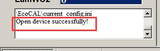
51 4.4 Ethernet communication mode UAV engine EFI installation manual-dle120-v1.7 Our custom ECU also support the Ethernet communication, if the ECU of EFI system supports the Ethernet communication, you can use this communication mode to connect ECU. You need to make Ethernet connect laptop with Ethernet cable, choose the Ethernet device Type, click Search Module, after IP and Port appear, then click Open Device to open the Ethernet device. And if you don t want to use the Ethernet, you also need to click Close Device to close the Ethernet device. Note: when you click the Open Device, if the equipment is existed and working, the message will pop up, Open device successfully! Then you can connect to ECU. 51
52 52
53 Chapter 5 Initial test after the installation Before you do the initial test of the EFI kit, make sure the installation is done as the previous section. Key-on and KEY-ON ONLY! You should hear fuel pump noise running for a few seconds, if this is not happening, you must have some wiring problem. Re-check all your wires! If every wire is sure correctly connected, then the ECU may have a problem. If you hear the fuel pump running and then stop, this indicates the ECU is working. Now you can fill the fuel tank with the regular gasoline. Repeat the above step 3 times, to make sure the fuel supply lines are filled up with fuel. No air pocket! No bubbles! Sometime, you have to manually purge out all the air bubbles in the fuel supply system, because it is possible that if the fuel pump itself has a lot bubbles in there, it could not pump fuel at all, it is only spinning like idle without load. In this case the noise of fuel pump is little higher pitch than with fuel pumping. In this case you will not be able to start no matter what, because no fuel pumping. If you have any doubt that the fuel supply system has some air pocket or air bubbles, you can un-plug the high pressure fuel line, pointing it into a bottle, and key-on, you should see fuel sprout out if fuel pump is working and no air bubbles. In many cases, you can visually see the fuel flow out of the fuel pressure regulator and return back to the tank if the fuel supply system is working normally. This is another indication you can check. After you make sure the fuel supply system is working normally, try to rotate the propeller to start the engine. 53
54 First time you start the engine, there may be still some air bubbles in the fuel supply system needs to be purged. So don t be surprised that the first start takes longer, or even you need to start multiple times to be successful. If the engine does not start, go to the next section for diagnosis. After the engine starts, if it s rough idling; please open a little throttle, make the engine is at idle, then tune the fuel injection. After the idle stabilizes, run the engine in a steady state (constant throttles or constant speeds) at different throttle/speeds. Then to tune the fuel maps to get the best performance. Then you can try different transient conditions, like fast opening of the throttle, etc. My engine does not start, why? 1) Have you followed the installation manual completely? 1.1) Can you tell that the ECU is controlling the fuel pump? 1.1.1) when you turn on the key, do you hear the fuel pump running for a few seconds, and then stop? If not, you have wiring issues ) Key-off for 3s, and key-on, do you hear the fuel pump running for a few seconds, and then stop? If not, you have wiring issues ) Every time when you try to start the engine (engine spins), do you hear the fuel pump running until engine stalls? If not, your wiring has issues. 1.2) Do you have the fuel pump installed correctly? 1.2.1) is the fuel pump lower than the tank? The fuel pump must be lower than the tank to avoid fuel starvation. The fuel pump can be higher than the injector, if limited by the space ) is there bubbles in the fuel line? If yes, please move the bubbles out of the fuel line first. 54
55 1.2.3) Do you have a fuel return line back to the fuel tank? Our EFI kit currently needs a way to return the fuel to the tank ) is there impurity in the gasoline? Check your fuel filter. 1.3) Do you have the ignition pick up sensor connected correctly? 1.3.1) Do you have a correct pick up signal input to ECU (Hall sensor wire) on the harness? 1.3.2) Do you have the ground wire of pickup sensor connected to ECU ground wire? 1.3.3) Are you using the stock ignition system (to isolate the starting problem, please use the stock ignition system)? 1.3.4) Can you tell the spark plug is firing whey you try to start? 2) Do you have the MIL Lamp on (if your harness comes with a MIL Lamp installed)? If yes, go to EcoCAL installation. 3) Install the EcoCAL (coming in the CD, or downloadable at our website): 3.1) EcoCAL does not support Windows Vista at this moment. Please use Windows XP (the most tested environment), or Win7, Win8. 3.2) you installed the EcoCAL into your computer, but it does not talk to the ECU: please check your USB adaptor is fully plugged in. And EcoCAL communication setting is set as USB. Or better: use an old computer which has a built-in COM port to rule out the USB converter problem. 3.3) establish the communication between the EcoCAL and the ECU: Go to menu->run->start Measuring, you should see the gauges starting to show values. 3.4) Read diagnostic trouble codes by go to: Go to menu->diagnostics->ecu Diagnostics 4) With the EcoCAL communicating with ECU, do the below tests: 55
56 4.1) Try to start the engine (with the engine spinning), Read the variables in EcoCAL: 4.2) Does the signal "RPM" changing from 0 to some value > 300rpm? 5) To rule out the problem of the ignition pickup sensor, do the below tests: 5.1) disconnect both CKP wire and GND wire from the ignition pickup sensor and tape them; 5.2) make sure the stock ignition system is untouched; 5.3) Try to start the engine, and check the below: 5.4) Does the signal "RPM" changing from 0 to some value > 300rpm? 5.5) if the above is NO, you could have some wiring problem. If the above is YES, you could have fuel supply issue: air bubbles in the fuel lines, or fuel clogged somewhere. With all the above questions and tests done, you still cannot figure out why the engine does NOT start, please contact us directly: info@ecotrons.com 56

57 Chapter 6 How do we know the fuel injector flow rate See the mark of the fuel injector as shown below, This fuel injector flow rate is 248g/min. Note: It does not recommend removing the injector cap, as it may lead to damage the injector cap. Refer to the comparison table, Item MEV1- MEV1- MEV1- MEV1- MEV1- MEV1- MEV1-248 Flow (g/min) If there is no mark on the fuel injector, contact us for more information about the fuel injector. 57
58 Chapter 7 UAV EFI Maintenance UAV EFI check list before flight: a. 12v power supply i. Before each flight, check the 12V power supply to EFI, and make sure the voltage is 12V or higher. ii. Check the 12V negative wire is grounded and shares the same ground as the engine block. iii. Check the charging system is functioning, and no deficiency (with the engine running). b. EFI i. Check the main connector plugged in and secured by screws, before each flight; ii. Check all wires are neat and secured, before each flight; iii. Check the ECU is mechanically secured; cushioned from severe vibration, not directly exposed to water or contamination, etc. iv. Before each flight, check the correct version of software, and correct version of calibration by connecting to the laptop and start the measuring. If the firmware is incorrect, you will be warned by software mismatch. If the calibration is incorrect, you will be popped up with burn to ECU. Make sure your laptop has the CORRECT software (A2L file) and correct calibration (CAL file) opened in EcoCAL before you do this check. c. Hall Effect Sensor i. Check the sensor wires and sensor connector before each flight; ii. Check the RPM reading before each flight, in EcoCAL, by spinning the propeller and read the RPM gauge. If the engine starts and runs stably, the Hall sensor is OK. iii. If there is no RPM reading, and/or there is no injection, the first thing is to check the Hall sensor. You may need to swap a new Hall sensor to verify. d. BARO Sensor 58
59 i. Before each flight, check the brass tube on the ECU is not blocked (which is for the on-board Baro pressure sensor) ii. Before each flight, check the MAP gauge reading, in EcoCAL. It shall match the ambient pressure, like 101kPa, or 14psi. e. TPS Sensor i. Check the sensor wires and sensor connector before each flight; ii. Check the TPS reading before each flight, in EcoCAL. Use servo to move the throttle from 0-100% and back to 0% and verify in EcoCAL the TPS gauge is following. f. IAT i. Check the sensor wires before each flight; ii. Check sensor reading before each flight, in EcoCAL. IAT gauge reading should match the engine surrounding temperature. Note, you can change the reading to Fahrenheit by going to menu -> setting -> toggle units. iii. Check the sensor integrity physically every 50 hours, make sure no crack, and no carbon residual, etc. g. Temp Sensor (CHT) i. Check the sensor wires before each flight; ii. Check sensor reading before each flight, in EcoCAL. ECT gauge reading should match the cylinder head temperature. Note, you can change the reading to Fahrenheit by going to menu -> setting -> toggle units. iii. Check the sensor integrity physically every 50 hours, make sure no crack, and no carbon residual, etc. h. Fuel Injector i. Check the injector wires before each flight; ii. Check the fuel injection atomization every 50 hours. This means, pull out the injector from the throttle body, spin the engine, check the injection squirt and make sure it is misty. iii. If it is not misty, check 2 things: #1: check the fuel pressure, with a fuel pressure gauge ; #2: if fuel pressure is stable at 3 bar or 43psi, then swap the injector and check again from step (i). i. Throttle Servo 59
60 i. Check the servo wires and connector before each flight; ii. Before each flight, visually check the servo assembly, no cracks, and no loose parts. iii. Before each flight, visually check the throttle is synchronized with the servo movement. If you see some lag or dead zone between the servo and throttle, you need re-adjust the mechanical link between the servo and the throttle. iv. If you have a TPS sensor installed, you only need to check that the servo can drive the throttle from 0 to 100% and then back to 0%. Read the TPS position in EcoCAL when you are moving the servo. v. If you do NOT have a TPS sensor installed, and you are using the servo control PWM signal as equivalent TPS signal, then you need to verify the servo PWM signal has a linear relation to the equivalent TPS signal. The way to verify is to use servo drive the throttle from 0-100% and back to 0%, and monitor the TPS gauge in EcoCAL, make sure the TPS gauge is moving proportionally with the servo movement (slowly). vi. If you use the servo control PWM signal as the equivalent TPS signal, and if you re-adjusted the servo-throttle linkage, you must re-calibrate the servo-throttle linear relation. See manual for how to. vii. Every 200 hours, change to a new servo. j. Fuel Pump i. Before each flight, check the fuel pump wires and connector before each flight; ii. Before each flight, check the fuel tank which should have enough fuel, and fuel lines are fulfilled with fuel and no air pocket. If you see any air pocket, disconnect the fuel line, and purge it out. iii. Visually check fuel lines, and make sure no severe bending or kinks in the lines. iv. Key-on, you should hear some fuel pump running noise for a few seconds, and you shall visually see the fuel is flowing through the whole fuel supply system. Or simply, you shall see fuel returning back to the tank (at the fuel pressure regulator returning line). If 60
61 you hear the fuel pump running noise but no fuel flowing, you shall check the fuel supply to the pump, or air pocket in the lines. v. Every 50 hours, check the fuel pressure with a fuel pressure gauge, and make sure the fuel pressure can be maintained at 3 bar or 45psi at all RPMs, including the WOT (wide open throttle running). k. Fuel pressure Regulator i. Check the same thing as you check the fuel pump; 2. Throttle body, what needs to be maintained. i. Before each flight, check the throttle body is mechanically secured to the engine, no cracks, no loose bolts; ii. Every 50 hours, take off the throttle body, and visually check the integrity of the throttle body, no cracks, no carbon, no loose parts, etc. Clean it if there is any residual. iii. Every 50 hours, check the throttle body gaskets, no worn, no leaking. 3. Ignition module (CDI). i. Before each flight, check the wires and connector to the CDI module. ii. Before each flight, if the engine does not start, and you know the fuel system is OK, then check the ignition system: pull out the spark plug(s), hold it against the engine block, spin the engine, and check whether there is spark. If there is no spark at all, and the spark plug looks clean, then check the CDI module. You may need to swap to a new CDI module to verify. If the spark is too weak, then swap to a new spark plug and check again, if still the weak spark, then check the CDI module. iii. Every 50 hours, check the spark plugs. If dirty or worn, swap them. 4. Air filter. 5. Engine life i. Change Air Cleaner every 50 hours or sooner as needed; i. Typically a UAV engine has a life expectancy of 200 hours, check the engine manufacture data; 61
62 6. Clean engine i. Need to de-carb engine every 50 hours when using 100LL Fuel; 7. Engine exhaust and muffler i. Mufflers should be soaked in cleaner every 50 hours and dry before use; ii. Exhaust(s) inspected after and before each flight 8. Multiple-Check Does the fuel pump turn on for a few seconds when powering on the ECU? Do you hear the relay ticking when power on the ECU? Does engine start normally? Is there a RPM reading by ECU? Is there any fuel injection when engine cranks? When the fuel pump is running, (with key on), do you see fuel flowing in the fuel line? Are there bubbles in the fuel hose? Power on the EFI system, and see if the MIL lamp (LED) is on, it means there is an error in the system and please use EcoCAL to read DTC if the MIL lamp (LED) is on. Please visually check the throttle is synchronized with the servo movement again. Please check if the communication of the auto-pilot is normal. Before each flight, check all the above items of UAV EFI system again, and make sure they are all normal. You also need to check if the all other facilities of UAV are good. 62
RC Engine-EFI. Installation Manual
 RC Engine-EFI RC Engine Electronic Fuel Injection -- Conversion Kit For 120cc to 300cc engines Installation Manual ECOTRONS V1.2.3 http://www.ecotrons.com/ COPY RIGHTS ECOTRONS LLC ALL RIGHTS RESERVED
UAV engine EFI components Specifications Manual
 UAV engine EFI components Specifications Manual -In miniature sizes - For 20cc to 300cc engines V1.7 COPY RIGHTS ECOTRONS LLC ALL RIGHTS RESERVED Http://www.ecotrons.com Note: If you are not sure about
SE-EFI. Junior 206. Installation Manual
 SE-EFI Small Engine Electronic Fuel Injection Conversion Kit Junior 206 Installation Manual ECOTRONS LLC V1.3 COPY RIGHTS ECOTRONS ALL RIGHTS RESERVED Note: this manual is written based on a conversion
SE-EFI. Suzuki DR-650. Installation Manual
 SE-EFI Small Engine Electronic Fuel Injection Conversion Kit Suzuki DR-650 Installation Manual ECOTRONS LLC V1.3 Copy rights ECOTRONS LLC 1 COPY RIGHTS ECOTRONS ALL RIGHTS RESERVED Note: this manual is
UAV engine EFI components Specifications Manual
 UAV engine EFI components Specifications Manual -In miniature sizes - For 20cc to 300cc engines V2.1 COPY RIGHTS ECOTRONS LLC ALL RIGHTS RESERVED Http://www.ecotrons.com Note: If you are not sure about
UAV EFI components In miniature sizes
 UAV EFI components In miniature sizes For small 2 and 4 stroke engines in 20cc- 200cc ranges V1.5 ECOTRONS LLC 2016/1 Copyright Ecotrons All rights reserved Contents 1. UAV EFI System Overview... 2 1.1
SE-EFI. Installation Manual
 SE-EFI Small Engine Electronic Fuel Injection -- Conversion Kit Installation Manual ECOTRONS V2.8 http://www.ecotrons.com/ COPY RIGHTS ECOTRONS LLC ALL RIGHTS RESERVED Note: many EFI parts in this manual
MAP Sensor. Technical Spec COPY RIGHTS ECOTRONS ALL RIGHTS RESERVED ECOTRONS LLC. -Manifold Absolute Pressure Sensor
 MAP Sensor -Manifold Absolute Pressure Sensor Technical Spec ECOTRONS LLC COPY RIGHTS ECOTRONS ALL RIGHTS RESERVED Note: If you are not sure about any specific details, please contact us at info@ecotrons.com.
Engine Control Unit. (ECU) Technical Spec ECOTRONS LLC COPY RIGHTS ECOTRONS ALL RIGHTS RESERVED
 Technical Spec ECOTRONS LLC COPY RIGHTS ECOTRONS ALL RIGHTS RESERVED") Engine Control Unit (ECU) Technical Spec ECOTRONS LLC COPY RIGHTS ECOTRONS ALL RIGHTS RESERVED Note: If you are not sure about any specific details, please contact us at info@ecotrons.com. Product: Type:
Engine Control Unit (ECU) Technical Spec ECOTRONS LLC COPY RIGHTS ECOTRONS ALL RIGHTS RESERVED Note: If you are not sure about any specific details, please contact us at info@ecotrons.com. Product: Type:
20-pin ECU Technical Specs. Engine Control Unit. (ECU) Technical Spec ECOTRONS LLC COPY RIGHTS ECOTRONS ALL RIGHTS RESERVED
 Technical Spec ECOTRONS LLC COPY RIGHTS ECOTRONS ALL RIGHTS RESERVED") Engine Control Unit (ECU) Technical Spec ECOTRONS LLC COPY RIGHTS ECOTRONS ALL RIGHTS RESERVED Note: If you are not sure about any specific details, please contact us at info@ecotrons.com. Product: Part#:
Engine Control Unit (ECU) Technical Spec ECOTRONS LLC COPY RIGHTS ECOTRONS ALL RIGHTS RESERVED Note: If you are not sure about any specific details, please contact us at info@ecotrons.com. Product: Part#:
Small engine EFI conversion kits Hall Effect Sensor technical spec. Hall Effect Sensor. Technical Spec ECOTRONS LLC COPY RIGHTS ECOTRONS
 Hall Effect Sensor Technical Spec ECOTRONS LLC COPY RIGHTS ECOTRONS ALL RIGHTS RESERVED Note: If you are not sure about any specific details, please contact us at info@ecotrons.com. Copy rights ECOTRONS
Micro Gear Fuel Pump System
 Micro Gear Fuel Pump System User Manual V1.5 ECOTRONS LLC COPY RIGHTS ECOTRONS ALL RIGHTS RESERVED Note: If you are not sure about any specific details, please contact us at info@ecotrons.com. Index Page
ALM LSU ADV Manual. Accurate Lambda Meter With built-in LED display COPY RIGHTS ECOTRONS LLC ALL RIGHTS RESERVED.
 ALM LSU ADV Manual Accurate Lambda Meter With built-in LED display COPY RIGHTS ECOTRONS LLC ALL RIGHTS RESERVED Http://www.ecotrons.com Note: If you are not sure about any specific details, please contact
Hall Effect Sensor. Technical Spec ECOTRONS LLC COPY RIGHTS ECOTRONS ALL RIGHTS RESERVED
 Hall Effect Sensor Technical Spec ECOTRONS LLC COPY RIGHTS ECOTRONS ALL RIGHTS RESERVED Note: If you are not sure about any specific details, please contact us at info@ecotrons.com. Product: Hall Effect
ALM-Inline. Accurate Lambda Meter V1.1.2 COPY RIGHTS ECOTRONS LLC ALL RIGHTS RESERVED.
 ALM-Inline Accurate Lambda Meter V1.1.2 COPY RIGHTS ECOTRONS LLC ALL RIGHTS RESERVED Http://www.ecotrons.com Note: If you are not sure about any specific details, please contact us at info@ecotrons.com.
IAT. Technical Spec COPY RIGHTS ECOTRONS ALL RIGHTS RESERVED. -Intake air temperature sensor ECOTRONS LLC
 IAT -Intake air temperature sensor Technical Spec ECOTRONS LLC COPY RIGHTS ECOTRONS ALL RIGHTS RESERVED Note: If you are not sure about any specific details, please contact us at info@ecotrons.com. Product:
Small engine EFI tuning guide V2.8 SE-EFI. Small Engine Electronic Fuel Injection. Tuning Guide V2.8 ECOTRONS. Copyright ECOTRONS LLC
 SE-EFI Small Engine Electronic Fuel Injection Tuning Guide V2.8 ECOTRONS Copyright ECOTRONS LLC COPY RIGHTS ECOTRONS ALL RIGHTS RESERVED Note: this tuning guide will be under continuous improvements. Contact
Small engine EFI conversion kits VRS technical spec VRS SENSOR. Technical Spec ECOTRONS LLC COPY RIGHTS ECOTRONS ALL RIGHTS RESERVED
 VRS SENSOR Technical Spec ECOTRONS LLC COPY RIGHTS ECOTRONS ALL RIGHTS RESERVED Note: If you are not sure about any specific details, please contact us at info@ecotrons.com. Copy rights ECOTRONS LLC 1
SimMotor User Manual Small Engine Simulator and HIL V COPY RIGHTS ECOTRONS LLC All rights reserved
 V2.3.1 SimMotor User Manual Small Engine Simulator and HIL V2.3.1 COPY RIGHTS ECOTRONS LLC All rights reserved Http://www.ecotrons.com Table of Contents Read before you start:...1 Why do I need SimMotor?...2
DA 35/70 EFI MIL SPEC
 DA 35/70 EFI MIL SPEC Electronic Fuel Injected Engines OWNER S MANUAL Table of Contents Section Page 1. General Safety 3 2. Un-Packing Your Engine 4 3. Getting Started 7 4. Maintenance 9 5. Absolute Ratings
MALLORY FIRESTORM CD MULTI COIL HARDWARE INSTALLATION - PN 69150C / 69150R
 FORM 69150C/R MALLORY FIRESTORM CD MULTI COIL HARDWARE INSTALLATION - PN 69150C / 69150R To ensure you are using the most current instruction sheet, please visit www.malloryfirestorm.com. CAUTION! The
MaxxECU quickstart guide ( )
") Be a tuning mastermind. Like us. MaxxECU quickstart guide (2019-02-01) Online help! maxxecu.com/support Wiring diagrams Installation help Pinout Support maxxecu.com/support Legal disclaimer All performance
Be a tuning mastermind. Like us. MaxxECU quickstart guide (2019-02-01) Online help! maxxecu.com/support Wiring diagrams Installation help Pinout Support maxxecu.com/support Legal disclaimer All performance
Small engine EFI conversion kits Intake air temperature sensor technical spec IAT. -Intake air temperature sensor. Technical Spec ECOTRONS LLC
 IAT -Intake air temperature sensor Technical Spec ECOTRONS LLC COPY RIGHTS ECOTRONS ALL RIGHTS RESERVED Note: If you are not sure about any specific details, please contact us at info@ecotrons.com. Copy
MegaSquirt III for Gen 3 HEMI. Hardware Install THE FOLLOWING SENSOR PART NUMBERS APPLY TO ALL HARNESSES FOR ENGINES 2004 TO CURRENT:
 MegaSquirt III for Gen 3 HEMI MegaSquirt controllers are experimental devices intended for educational purposes. MegaSquirt controllers are not for sale or use on pollution controlled vehicles. Check the
Mid-size Fuel Pump. Technical Spec ECOTRONS LLC COPY RIGHTS ECOTRONS ALL RIGHTS RESERVED
 Mid-size Fuel Pump Technical Spec ECOTRONS LLC COPY RIGHTS ECOTRONS ALL RIGHTS RESERVED Note: If you are not sure about any specific details, please contact us at info@ecotrons.com. Product: Part#: Comment:
QUICK START GUIDE 199R10546
 QUICK START GUIDE 199R10546 1.0 Overview This contains detailed information on how to use Holley EFI software and perform tuning that is included within the software itself. Once you load the software,
MALLORY FIRESTORM CD MULTI COIL HARDWARE INSTALLATION - PN 69050S / 69050R
 FORM 69050S/R MALLORY FIRESTORM CD MULTI COIL HARDWARE INSTALLATION - PN 69050S / 69050R To ensure you are using the most current instruction sheet, please visit www.malloryfirestorm.com. CAUTION! The
Small engine EFI conversion kits Engine temperature sensor technical spec ECT. -Engine Temperature sensor. Technical Spec ECOTRONS LLC
 ECT -Engine Temperature sensor Technical Spec ECOTRONS LLC COPY RIGHTS ECOTRONS ALL RIGHTS RESERVED Note: If you are not sure about any specific details, please contact us at info@ecotrons.com. Copy rights
MS3-Pro LSx Drop On Harness
 24x MS3-Pro LSx Drop On Harness For engines with 24X crank triggers Thank you for buying our drop on wiring harness! We have designed this harness to support anything from a stock motor swapped into a
In-Tank Fuel Pump. Technical Spec ECOTRONS LLC COPY RIGHTS ECOTRONS ALL RIGHTS RESERVED
 In-Tank Fuel Pump Technical Spec ECOTRONS LLC COPY RIGHTS ECOTRONS ALL RIGHTS RESERVED Note: If you have problems or need more detail, please contact us at info@ecotrons.com. Product: Part#: Comment: In-Tank
Small Size Fuel Pump
 Small Size Fuel Pump Technical Spec ECOTRONS LLC COPY RIGHTS ECOTRONS ALL RIGHTS RESERVED Note: If you are not sure about any specific details, please contact us at info@ecotrons.com. Copy rights ECOTRONS
DA 150 EFI. Electronic Fuel Injected Engines OWNER S MANUAL
 DA 150 EFI Electronic Fuel Injected Engines OWNER S MANUAL Table of Contents Section Page 1. General Safety 3 2. Un-Packing Your Engine 4 3. Getting Started 8 a. Hardware Installation 9 b. Transmitter/Receiver
Adaptronic esel020 Select ECU for Nissan S13 240SX (KA24DE) / RNN14 GTiR / SR20VE
 / RNN14 GTiR / SR20VE") 1 P a g e Adaptronic esel020 Select ECU for Nissan S13 240SX (KA24DE) / RNN14 GTiR / SR20VE Applicable vehicles / engines: Nissan S13 KA24DE 240SX US Market Nissan N14 SR20DET / SR20VE - Pulsar GTi-R /
1 P a g e Adaptronic esel020 Select ECU for Nissan S13 240SX (KA24DE) / RNN14 GTiR / SR20VE Applicable vehicles / engines: Nissan S13 KA24DE 240SX US Market Nissan N14 SR20DET / SR20VE - Pulsar GTi-R /
Fuel Injection System
 7. Fuel Injection System XCITING 400i Fuel Injection System This chapter covers the location and servicing of the fuel system components for the KYMCO XCITING 400i. Air box... 7-2~7-5 Fuel Tank... 7-6~7-10
Oregon Fuel Injection
 2003 2007 Dodge 5.9L Diesel Diagnostics In order to do proper diagnostics you will need a scan tool and some special tools available from Miller Special Tools http://millerspecialtools.spx.com. High Pressure
1998 ENGINE PERFORMANCE. General Motors Corp. - Basic Diagnostic Procedures - 5.7L
 INTRODUCTION 1998 ENGINE PERFORMANCE General Motors Corp. - Basic Diagnostic Procedures - 5.7L The following diagnostic steps will help prevent overlooking a simple problem. This is also where to begin
FAST XIM. XIM Unit Installation
 1 INSTRUCTIONS XIM Thank you for choosing products; we are proud to be your manufacturer of choice. Please read this instruction sheet carefully before beginning installation, and also take a moment to
Property of American Airlines
 Gen. II Ford 300 Install 1775 N. Lapeer Rd. Unit B Oxford, MI 48371 248-393-1621 TABLE OF CONTENTS 1. Kit Contents....3 2. Installation Instructions.. 4 3. Component Description.....10 4. Final Checks....12
MARELLI SRA EDL8 ECU
 MARELLI SRA EDL8 ECU INTRODUCTION AIM has developed special applications for many of the most popular ECUs; by special applications we mean user-friendly systems which allow to easily connect your ECU
OMEM200 Tuning Manual 3v Series ECU. Tuning Manual OMEM200.
 200 Series ECU Tuning Manual OMEM200 www.omextechnology.com 0 1 Introduction... 3 1.1 What this manual covers... 3 1.2 Notation Used in This Manual... 3 2 Software... 4 3 Sensor Setup... 5 3.1 Throttle
SP4 DOCUMENTATION. 1. SP4 Reference manual SP4 console.
 SP4 DOCUMENTATION 1. SP4 Reference manual.... 1 1.1. SP4 console... 1 1.2 Configuration... 3 1.3 SP4 I/O module.... 6 2. Dynamometer Installation... 7 2.1. Installation parts.... 8 2.2. Connectors and
BASIC DIAGNOSTIC PROCEDURES
 BASIC DIAGNOSTIC PROCEDURES 2001 Chevrolet Camaro 2001 ENGINE PERFORMANCE Basic Diagnostic Procedures - Cars Except Metro & Prizm MODEL IDENTIFICATION MODEL IDENTIFICATION Body Code (1) Model C... Park
APSX WIDEBAND D2 AFR CONTROLLER GAUGE. Installation and User Manual. APSX WIDEBAND D2 Manual V1.0
 APSX WIDEBAND D2 AFR CONTROLLER GAUGE Installation and User Manual APSX WIDEBAND D2 Manual V1.0 You purchased a wideband gauge! BENCH TEST BEFORE INSTALLING IT! USE A RELIABLE 12V POWER > 5AMP Stock (OEM)ECU
MegaSquirt III for LS Style Engines. Hardware Install. 1. Disconnect and remove the battery from the vehicle.
 MegaSquirt III for LS Style Engines MegaSquirt controllers are experimental devices intended for educational purposes. MegaSquirt controllers are not for sale or use on pollution controlled vehicles. Check
Large Size Fuel Pump. Technical Spec
 Large Size Fuel Pump Technical Spec ECOTRONS LLC COPY RIGHTS ECOTRONS ALL RIGHTS RESERVED Note: If you are not sure about any specific details, please contact us at info@ecotrons.com. Copy rights ECOTRONS
Instruction of connection and programming of the VECTOR controller
 Instruction of connection and programming of the VECTOR controller 1. Connection of wiring 1.1.VECTOR Connection diagram Fig. 1 VECTOR Diagram of connection to the vehicle wiring. 1.2.Connection of wiring
DFS-1000 Wiring Diagrams and PC Software Installation.
 DFS-1000 Wiring Diagrams and PC Software Installation. For Technical Support Please contact your dealer or email seellc@mchsi.com 1 Important Information - When using a conventional style ignition coil
DRH Performance ECU. Porsche Jenvey ITB conversion kit. Kit Contents. Aim of conversion / Expected results. Canems Engine Management Solutions
 DRH Performance ECU Porsche 911 3.2 Jenvey ITB conversion kit Kit Contents Jenvey CKPE02 ITB kit (manifolds, fuel rails, throttle bodies and air horns) Stainless braided high pressure fuel hoses (Carrera
Powertrain DTC Summaries EOBD
 Powertrain DTC Summaries Quick Reference Diagnostic Guide Jaguar S-TYPE V6, V8 N/A and V8 SC 2002.5 Model Year Refer to pages 2 9 for important information regarding the use of Powertrain DTC Summaries.
ITCEMS950 Idle Timer Controller - Engine Monitor Shutdown Isuzu NPR 6.0L Gasoline Engine
 Introduction An ISO 9001:2008 Registered Company ITCEMS950 Idle Timer Controller - Engine Monitor Shutdown 2014-2016 Isuzu NPR 6.0L Gasoline Engine Contact InterMotive for additional vehicle applications
SP5 INSTALLATION AND SETUP MANUAL
 SP5 INSTALLATION AND SETUP MANUAL 1 Installation 1.1 Introduction The SP5 System consists of a Data Acquisition unit (DAQ) with two complete Roller control channels, each Roller Control Channel consists
 Page 1 of 18 2004 PCED On Board Diagnostics SECTION 5: Pinpoint Tests Procedure revision date: 10/26/2007 H: Fuel Control H: Introduction H1 PERFORM THE KOER SELF-TEST Engine at normal operating temperature.
PLUG & PLAY. Quick Start Guide. GM LS 58X Drop On Harness. MS3Pro ULTIMATE
 Quick Start Guide PLUG & PLAY GM LS 58X Drop On Harness MS3Pro ULTIMATE For GM LS Engines with 58X Crank Triggers Thank you for your purchase and support for American made products! We have designed this
Motronic September 1998
 The Motronic 1.8 engine management system was introduced with the 1992 Volvo 960. The primary difference between this Motronic system and the previous generation of Volvo LH-Jetronic engine management
General Service Information
 KYMCO MXU 500i/700i Repair Manual Fuel System MXU 700i 3.Fuel System MXU 700i This chapter covers the location and servicing of the fuel system components for the fuel injected KYMCO MXU 700i models. 1.Airbox...
DTC P0174 Fuel Trim System Lean Bank 2
 2000 Chevrolet/Geo S10 Pickup - 4WD DTC P0174 Fuel Trim System Lean Bank 2 Circuit Description In order to provide the best possible combination of driveability, fuel economy, and emission control, the
Error codes Diagnostic plug Read-out Reset Signal Error codes
 Error codes Diagnostic plug Diagnostic plug: 1 = Datalink LED tester (FEN) 3 = activation error codes (TEN) 4 = positive battery terminal (+B) 5 = ground Read-out -Connect LED tester to positive battery
Handheld Controller Feature Definitions
 Basic Settings: These values and options allow Engine CID = Total Engine cubic inches Cam Mild-Wild 1-4 = This is the way to select a specific volumetric efficiency table that is specially tailored to
L (LU4, LJ3, L88) used in Saab 9-5 ENGINE DIAGNOSTIC PARAMETERS
 used in Saab 9-5 ENGINE DIAGNOSTIC PARAMETERS") Catalytic Converter Monitoring P0420 Front vs. Rear O2 sensor signal Evaluated data 1,75 times FTP std 80 (unitless) Coolant temp Throttle Delta load, positive Delta load, negative Engine speed, man. trans
Catalytic Converter Monitoring P0420 Front vs. Rear O2 sensor signal Evaluated data 1,75 times FTP std 80 (unitless) Coolant temp Throttle Delta load, positive Delta load, negative Engine speed, man. trans
Honda Accord/Prelude
 Honda Accord/Prelude 1984-1995 In Tank Fuel Pumps TEST 1. Turn the ignition OFF. 2. On the Accord, remove the screws securing the underdash fuse box to its mount. Remove the fuel cut off relay from the
ECT Display Driver Installation for AP2 Module
 ECT Display Driver Installation for AP2 Module Overview The ECT Display Driver is a small module with a removable wire harness that mounts behind the driver's foot well cover. All wiring connections are
Lingenfelter NCC-002 Nitrous Control Center Quick Setup Guide
 Introduction: Lingenfelter NCC-002 Nitrous Control Center Quick Setup Guide The NCC-002 is capable of controlling two stages of progressive nitrous and fuel. If the NCC-002 is configured only for nitrous,
PowerJet Sequential Injection INDEX. 1 Introduction 1.1 Features of the Software. 2- Software installation
 INDEX 1 Introduction 1.1 Features of the Software 2- Software installation 3 Open the program 3.1 Language 3.2 Connection 4 Folder General - F2. 4.1 The sub-folder Error visualization 5 Folder Configuration
Prins autogassystemen b.v. Veldhoven
 Prins autogassystemen b.v. Veldhoven MOUNTING INSTRUCTION ENGINE CONVERSION SET MAKE OF AUTOMOBILE: TYPE: ASTRA PISTON DISPLACEMENT: 2000 cc MT NUMBER OF VALVES: 16V ENGINE NUMBER: X20XEV INJECTION SYSTEM:
INDEX 1 Introduction 2- Software installation 3 Open the program 4 General - F2 5 Configuration - F3 6 - Calibration - F5 7 Model - F6 8 - Map - F7
 SET UP MANUAL INDEX 1 Introduction 1.1 Features of the Software 2- Software installation 3 Open the program 3.1 Language 3.2 Connection 4 General - F2 4.1 The sub-folder Error visualization 5 Configuration
Code 32. Diagnostic Trouble Code 32
 Code 32 Diagnostic Trouble Code 32 EGR Solenoid Circuit CIRCUIT DESCRIPTION The ECM operates a solenoid to control the Exhaust Gas Recirculation (EGR) valve. This solenoid is normally close EGR valve.
Installation Instructions for: EMS P/N and U Honda S2000
 Installation Instructions for: EMS P/N 30-1052 and 30-1052U 00-04 Honda S2000! WARNING: This installation is not for the tuning novice nor the PC illiterate! Use this system with EXTREME caution! The AEM
MAKE OF AUTOMOBILE: TYPE: V 70 PISTON DISPLACEMENT: 2521 NUMBER OF VALVES:
 MAKE OF AUTOMOBILE: TYPE: V 70 PISTON DISPLACEMENT: 2521 NUMBER OF VALVES: 20V ENGINE NUMBER: B5254T TRANSMISSION TYPE ( MT / AT ) AT VEHICLE CATEGORIES M or N PASSENGER CAR ( M ) TYPE VSI INJECTOR (COLOUR
Powertrain DTC Summaries OBD II
 Powertrain DTC Summaries Quick Reference Diagnostic Guide Jaguar X-TYPE 2.5L and 3.0L 2002 Model Year Revised January, 2002: P0706, P0731, P0732, P0733, P0734, P0735, P0740, P1780 POSSIBLE CAUSES Revised
Powertrain DTC Summaries EOBD
 Powertrain DTC Summaries Quick Reference Diagnostic Guide Jaguar X-TYPE 2.0 L 2002.25 Model Year Refer to page 2 for important information regarding the use of Powertrain DTC Summaries. Jaguar X-TYPE 2.0
Diagnostic Trouble Code (DTC) memory, checking and erasing
 memory, checking and erasing") Page 1 of 49 01-12 Diagnostic Trouble Code (DTC) memory, checking and erasing Check DTC Memory (function 02) - Connect VAS5051 tester Page 01-7 and select vehicle system "01 - Engine electronics". Engine
Page 1 of 49 01-12 Diagnostic Trouble Code (DTC) memory, checking and erasing Check DTC Memory (function 02) - Connect VAS5051 tester Page 01-7 and select vehicle system "01 - Engine electronics". Engine
Installation Instructions for: EMS P/N Acura Integra Acura 2.3CL Honda Accord Honda Civic
 Installation Instructions for: EMS P/N 30-6050 00-01 Acura Integra 98-99 Acura 2.3CL 98-02 Honda Accord 99-00 Honda Civic Thank you for purchasing an AEM Engine Management System. The AEM Engine Management
Installation Instructions Diesel Nitrous System (#82028)
") Installation Instructions Diesel Nitrous System (#82028) Thank you for choosing ZEX. If at any time you have questions regarding this or any of our products, please call our Nitrous Help support line at
Installation Instructions Diesel Nitrous System (#82028) Thank you for choosing ZEX. If at any time you have questions regarding this or any of our products, please call our Nitrous Help support line at
Products Kronenburg Management Systems. kms.vankronenburg.nl
 Products 2011 Kronenburg Management Systems kms.vankronenburg.nl Kronenburg Management Systems (KMS) is a complete line of engine management systems that offers you an extremely reliable and user-friendly
DTC P0172 Fuel Trim System Rich
 Page 1 of 6 1997 Chevrolet Cavalier Cavalier, Sunfire (VIN J) Service Manual Document ID: 47788 DTC P0172 Fuel Trim System Rich System Description A Closed Loop air/fuel metering system is used to provide
MULTIPOINT FUEL INJECTION (MPI) <4G9>
 <4G9>") MULTIPOINT FUEL INJECTION (MPI) 13C-1 MULTIPOINT FUEL INJECTION (MPI) CONTENTS GENERAL................................. 2 Outline of Changes............................ 2 GENERAL INFORMATION...................
MULTIPOINT FUEL INJECTION (MPI) 13C-1 MULTIPOINT FUEL INJECTION (MPI) CONTENTS GENERAL................................. 2 Outline of Changes............................ 2 GENERAL INFORMATION...................
Fuel Pressure Regulator. Technical Spec
 Fuel Pressure Regulator Technical Spec ECOTRONS LLC COPY RIGHTS ECOTRONS ALL RIGHTS RESERVED Note: If you are not sure about any specific details, please contact us at info@ecotrons.com. Product: Fuel
Adaptronic esel015 Select ECU for Nissan R32/R33/R34GTR Skyline and Z32 300ZX / Fairlady
 1 P a g e Adaptronic esel015 Select ECU for Nissan R32/R33/R34GTR Skyline and Z32 300ZX / Fairlady Applicable vehicles / engines: Nissan Skyline R32 (GTST and GTR) RB20DET and RB26DETT Nissan Skyline R33
Installation Instructions Dual Perimeter Plate Nitrous System (#82185)
") Installation Instructions Dual Perimeter Plate Nitrous System (#82185) Thank you for choosing ZEX. If at any time you have questions regarding this or any of our products, please call our ZEXTEK support
Installation Instructions Dual Perimeter Plate Nitrous System (#82185) Thank you for choosing ZEX. If at any time you have questions regarding this or any of our products, please call our ZEXTEK support
INSTRUCTIONS. #82044 Race Diesel Nitrous System
 INSTRUCTIONS #82044 Race Diesel Nitrous System Thank you for choosing ZEX products; we are proud to be your manufacturer of choice. Kit Parts List Description Qty. Description Qty. Nitrous Solenoid 2.088
BMW 2002 M42 Swap Notes-THIS IS NOT FINISHED
 BMW 2002 M42 Swap Notes-THIS IS NOT FINISHED This document is to help those that want to install an m42 into a BMW 2002. It is based around an e30 engine, trans, and wiring. You can use the e36 block/head/wiring
Installation Instructions for: EMS P/N Ford Mustang 5.0L
 Installation Instructions for: EMS P/N 30-1401 1994-95 Ford Mustang 5.0L! WARNING: This installation is not for the tuning novice nor the PC illiterate! Use this system with EXTREME caution! The AEM EMS
INSTRUCTIONS. #82028 Diesel Nitrous System. Thank you for choosing ZEX products; we are proud to be your manufacturer of choice.
 1 INSTRUCTIONS #82028 Diesel Nitrous System Thank you for choosing ZEX products; we are proud to be your manufacturer of choice. Why our nitrous system is better: 2 Performance enthusiasts know the potential
Installation Instructions for: EMS P/N Toyota Supra
 Installation Instructions for: EMS P/N 30-1110 1987-1988 Toyota Supra! WARNING: This installation is not for the tuning novice nor the PC illiterate! Use this system with EXTREME caution! The AEM EMS System
DA 120 EFI. Electronic Fuel Injected Engines OWNER S MANUAL
 DA 120 EFI Electronic Fuel Injected Engines OWNER S MANUAL Table of Contents Section Page 1. General Safety 3 2. Un-Packing Your Engine 4 3. Getting Started 8 a. Hardware Installation 9 b. Transmitter/Receiver
MARELLI MF4 Toyota ECU
 MARELLI MF4 Toyota ECU INTRODUCTION AIM has developed special applications for many of the most popular ECUs; by special applications we mean user-friendly systems which allow to easily connect your ECU
AIM Infotech. ViPec V44-V88 CAN Bus Base and CAN Bus Full protocol. Release 1.00
 AIM Infotech ViPec V44-V88 CAN Bus Base and CAN Bus Full protocol Release 1.00 This tutorial explains how to connect ViPec V44-V88 to AIM loggers using the CAN Bus. This communication protocol offers two
PSB-1 User Manual. Warning!
 PSB-1 User Manual Warning! The Oxygen Sensor used in this device gets very hot in operation. Do not touch a hot sensor. Do not let a hot sensor touch a combustible surface. Do not use the sensor with or
IT S ELECTRIC SWITCHING TO HOLLEY EFI YIELDS BETTER DRIVABILITY AND MORE POWER FOR A BOOSTED 68 FIREBIRD
 WORDS: Scott Parker PICTURES: By Redline Motorsports IT S ELECTRIC SWITCHING TO HOLLEY EFI YIELDS BETTER DRIVABILITY AND MORE POWER FOR A BOOSTED 68 FIREBIRD I t s been said many times, and often it has
Engine Cranks But Does Not Run
 Page 1 of 5 2000 GMC Truck GMC K Sierra - 4WD Sierra, Silverado, Suburban, Tahoe, Yukon (VIN C/K) Service Manual Engine Engine Controls - 4.8L, 5.3L, and 6.0L Diagnostic Information and Procedures Engine
Nistune Z32 ECU Modifications for R33 RB25DET Skyline Installation
 Nistune Z32 ECU Modifications for R33 RB25DET Skyline Installation Revision 8 10 July 2012 Thanks to Eric at DTA Motorsports, Skyline Stu and Andrew H for their help. Overview Fitting of the Z32 ECU is
Speed-Pro EFI Installation Manual
 Speed-Pro EFI Installation Manual Speed-Pro Electronics Installation Manual Page The wiring harness is labeled on each of the connectors to simplify installation. Your application may not require the use
Megasquirt EX, Installation Instructions document revision 1.4 (Includes also the version equipped with wasted-spark ignition)
") Megasquirt EX, Installation Instructions document revision 1.4 (Includes also the version equipped with wasted-spark ignition) General Megasquirt EX is a programmable engine control system, based on Megasquirt
Megasquirt EX, Installation Instructions document revision 1.4 (Includes also the version equipped with wasted-spark ignition) General Megasquirt EX is a programmable engine control system, based on Megasquirt
Installation Instructions for: EMS P/N Ford Mustang 5.0L
 Installation Instructions for: EMS P/N 30-1400 1986-93 Ford Mustang 5.0L! WARNING: This installation is not for the tuning novice nor the PC illiterate! Use this system with EXTREME caution! The AEM EMS
LAMBDA SENSOR CONTROLLER
 LAMBDA SENSOR CONTROLLER INSTALLATION & PROGRAMMING MANUAL version : V1.77 -V1.79 Manufacturer: AC Spółka Akcyjna. 15-182 Białystok, ul. 27 Lipca 64, Poland tel. +48 85 7438148, fax +48 85 653 8649 www.ac.com.pl,
Controller Ground (dual black 12awg) should be connected to chassis ground as close as possible to the battery.
 should be connected to chassis ground as close as possible to the battery.") 1. Overview The Maximizer 4 progressive nitrous controller operates one or two separate stages of nitrous based on either time, RPM, MPH, throttle percentage or boost pressure. Whether your engine is naturally
1. Overview The Maximizer 4 progressive nitrous controller operates one or two separate stages of nitrous based on either time, RPM, MPH, throttle percentage or boost pressure. Whether your engine is naturally
Installation Instructions for: EMS P/N Toyota Supra
 Installation Instructions for: EMS P/N 30-1130 1989-1992 Toyota Supra! WARNING: This installation is not for the tuning novice nor the PC illiterate! Use this system with EXTREME caution! The AEM EMS System
Cannondale Diagnostic Tool Manual
 Cannondale Diagnostic Tool Manual For vehicles (ATV & Motorcycles) equipped with the MC1000 Engine Management System Software CD P/N 971-5001983 Data Cable P/N 971-5001984 POTENTIAL HAZARD Running the
EFI HARNESS KIT , & Kit Contents: Power Harness : All Kits
 EFI HARNESS KIT 558-500, 558-501 & 558-502 Kit Contents: Main Harness 558-102: Kits 558-500 558-103: Kits 558-501 & 502 Power Harness 558-308: All Kits Injector Harness 558-200: Kits 558-500 & 502 558-201:
2012 Chevy Truck Equinox FWD L4-2.4L Vehicle > Locations > Components
 2012 Chevy Truck Equinox FWD L4-2.4L Vehicle > Locations > Components 2012 Chevy Truck Equinox FWD L4-2.4L Vehicle > Powertrain Management > Fuel Delivery and Air Induction > Description and Operation