Property of American Airlines
|
|
|
- Brook Shaw
- 5 years ago
- Views:
Transcription

1 Gen. II Ford 300 Install 1775 N. Lapeer Rd. Unit B Oxford, MI
2 TABLE OF CONTENTS 1. Kit Contents Installation Instructions Component Description Final Checks Installation tips (helpful installation pictures) Component Parts and Part Numbers Troubleshooting Diagnostic Trouble Codes ECM Pin Out and Wire Coding Wiring Diagram 39 2
3 Congratulations on the purchase of your Affordable Fuel Injection TBI system. We are confident that this purchase will give you the performance and driveability you deserve from your GSE equipment. The following instructions are intended to provide you with thorough description for installing your TBI system. If you do not understand any part of the instructions, need clarification or simply need more information, please e- mail us at: Please read through the instructions completely before beginning your installation. Many of your questions may be covered within this manual. Verify that all of the components are included in your shipment. 1. Wiring Harness 2. ECM 3. Throttle Body (with IAC and TPS) 4. ECT sensor (Engine Coolant Temp) 5. IAT sensor (Installed in throttle body) 6. MAP Sensor (Manifold Absolute Pressure) 7. Heated O2 Sensor with exhaust ring for installation 8. Fuel Pump Relay 9. Power Relay 10. Check Engine Light 11. Hall Effect distributor 12. Distributor module 13. Fuse protection link 14. Fuel filter 15. Inline Fuel Pump 16. Fuel Pressure regulator 17. Pre made fuel lines (optional) 18. ECM bracket and mounting hardware 19. ECM controlled start relay (optional) 20. Low fuel shut off sensor (optional) 21. Low fuel indicator light (optional) 22. Electric Fan Relay (optional) 3
4 NOTE: INSTALLATION INSTRUCTIONS THIS IS A CUSTOM FUEL INJECTION SYSTEM BUILT FOR YOUR GSE EQUIPMENT. AS WITH ALL CUSTOM PROJECTS SOME FABRICATION MAY BE REQUIRED. YOU MAY ALSO REQUIRE SOME SMALL PARTS THAT ARE NOT INCLUDED IN THE KIT. ECM The ECM is the central unit of the fuel injection system. This unit provides the signals that trigger the injectors. The ECM is mounted in the same location as the mechanical fuel pump was located. An extra thick gasket is supplied to insure a secure seal at this location. This is a state of the art ECM which is weatherproof, shockproof and heat proof. WIRING HARNESS The wiring harness included with this kit has been specially built for your unique application. This harness only includes the connectors and leads that are required to run your particular engine based upon the order specifications. Therefore, if there are leftover parts this indicates that an error has been made during assembly and installation of the system. Each connector will be marked with a label to the correct sensor that it is to be connected too. In the following section we will describe each sensor and the connector that attaches to it. The wiring harness is fabricated to allow the proper sensor to be hooked up to the respective connector. The keying of the connector will not allow for an improper connection. There is one fusible link required which is to be securely connected to the red battery wire after this wire is cut to length. Fuses which also protect the system are located integral to the relays in some applications. The PINK power wire needs to be attached to an Ignition 1 ( IGN1, battery power only with key on or in the crank position) power source. Ensure that this is an ignition 1 source. An ignition 1 source is 12volts available any time that the key is not in the off position. Also this PINK wire must have 12V while the vehicle is in the cranking mode (starting). This means the wire will have power when the key is on, or start, or back to on. Usually this wire can be taken from the proper terminal on the ignition switch, the power side of 4
5 the coil (+), or from the fuse box. The system will not work if power is not provided to the (PINK) ignition wire while cranking. The red wire is to be connected to a direct battery lead which has 12v always feeding it; a direct connection to the battery or starter relay is optimal. It is important that these wires are connected to the indicated source or your fuel injection system will not operate properly. A main fuse link is provided which is the main fuse protection for the entire system. This link is to be installed at the battery source and secured and sealed to the red battery wire. Two additional fuses are used for protection and located in the relays. It is very important that the ECM and components be supplied with proper voltage at all times. Improper operation of the charging system can result in system malfunctions and drivability issues. Included are two relays, a power relay and fuel pump relay. These relays are of the same design and can be used for either application. The power relay is used to ensure proper voltage is supplied to your system so as not to tax the current wiring of the vehicle with undue voltage requirements. The power relay connects to Ign. 1 feed to power up the relay (pink wire you connected above), and the input to the relay is battery powered. This battery lead is labeled and can be attached directly to the battery, the starter solenoid, or any other appropriate full time 12-volt supply. We have included a length of wire long enough to choose your own connection option. Insure that the main fuse circuit protection is installed between the battery power source and the red battery wire. A low temperature solder connector is also provided to provide a secure and sealed connection. The fuel pump relay is controlled by the ECM and no connections are required except for the power wire to the fuel pump itself. An ALDL connector is another extension of the harness which is located in your wiring harness at the back side of the engine.. This connector is a 4 pin weatherpak connector with a sealed connector installed to protect it from the elements. This connector allows the use of a C.A.N. based OBDII scan tool to read operational data of the unit as well as read and clear diagnostic codes. An OBDII connector with the proper Weatherpak termination is used with this to gain access to the data stream of the ECM. Two wires are also provided which connect to a check engine light. This light can be mounted in the dash, use an empty idiot light socket in the instrument panel, or mounted in a small bracket under the dash. It should be mounted in an area noticeable in case of any malfunctions. De-icer applications typically choose to mount the ALDL connector and the check engine light inside the control box. This allows for diagnostics and 5
6 troubleshooting for the technicians only. The wire from the ECM is the ground for the light. When a fault exists, or the system is in diagnostic mode, or the engine is not running with the key on, the light is illuminated. The other side of the light requires a 12v ignition feed that has been supplied and marked for this purpose. Several black wires with an eyelet on the end are to be bolted to an appropriate engine ground. Insure that you have cleaned the surface where this wire will mate to. Empty threaded holes in the intake manifold or cylinder head have been good locations for this wire. Two star washers have been provided to insure a good continuity to ground. It is advisable to run a separate ground wire from the battery to the frame of the vehicle. It is also advisable to run another ground wire from the location of the ground wire from the harness to the frame at the same mounting location as the wire from the battery. FUEL PUMP An external inline fuel pump has been included with your TBI system. This pump delivers a variable fuel pressure to the throttle body through the fuel pressure regulator. This regulator regulates the fuel pressure between psi and returned to the fuel tank. This pump should be mounted to the frame of your GSE equipment. If necessary weatherproof the pump by mounting a cover over it.. A fuel filter is to be installed in the fuel line PRIOR to the fuel pump. Premature failure of the pump can be the result of improper fuel filter installation. Some aftermarket high density fuel filters can cause a large drop in fuel pressure under load and are not recommended for use with your system. If you are using high density filters insure that you have proper fuel pressure during all modes of operation. If your equipment is fitted with an electric pusher or scavenger pump these pumps may not provide enough fuel flow for the system to operate properly. To insure that proper pressure is being maintained, monitor fuel pressure over time if you are using one of these pumps. In previous cases these pumps have been removed. A 12 or 16 Ga. pink wire labeled Fuel Pump, with sufficient length has been included with the wiring harness for the pump power feed. This wire comes from the fuel pump relay which can be mounted in a convenient under hood location. It may be desirable to enclose these relays in a plastic box or provide suitable protection from any elements. The mounting and the ground are very important for proper operation of the fuel pump. A ground wire is to be attached to a stable clean body ground or run back to a battery ground. An improper ground will result in insufficient fuel flow and/or premature pump failure. Mount the fuel pump in the bracket supplied or similar, to keep the pump noise from radiating into the vehicle. 6
7 You may want to prime the fuel feed line with gasoline to aid in the priming of the pump for proper operation. FUEL LINES & PRESSURE REGULATOR NOTE: Only use fuel line rated for fuel injection. If your kit was ordered with premade fuel line this line is already fuel injection rated. Steel line or braided fuel line is the most desirable for this application. Your TBI fuel injection system only requires one fuel line to the throttle body from the fuel pressure regulator for proper operation. This fuel line begins at the fuel pump, is T d into the side of the fuel pressure regulator and attached to the throttle body. (See Picture next section) An additional fuel line attaches to the bottom of the fuel pressure regulator and is used to return the low pressure regulated fuel back to the fuel tank. The ideal installation incorporates both the fuel feed and return lines attached to the fuel tank. Some fuel tanks are supplied with a tank vent for evaporative emission purposes. These fittings usually have a restriction incorporated internally and are not sufficient for a fuel return. If the restriction can be removed and the fitting is of sufficient size, this can be used for a return. Do not eliminate this fitting for evaporative emissions purposes if these items are still in use. Insure that any factory fittings that are on the fuel tank are free flowing and do not restrict the flow of fuel back to the fuel tank. On TUG brand units most fuel tanks have two fittings on the bottom of the tank that can be used. The one fitting that is currently used can be used for the feed line to the fuel pump. The other plugged line can be used as a return line. This second fitting has a tube internally in the fuel tank that allows for a return of the fuel higher in the tank; insure that you do not use this for the feed line. Some stations have chosen to install a shut off valve in the feed line prior to the fuel filter for easier fuel filter service purposes. THROTTLE BODY Your AFI throttle body is a direct replacement for your 1 bbl. carburetor. The air cleaner stud mounting bar on your current carburetor is to be removed and installed onto your new throttle body. The throttle lever is positioned similar to your throttle lever on your carburetor. The throttle cable will attach to your new throttle body in the same manner as your carburetor. If your current carburetor has an additional throttle return spring it is advisable to maintain this same return spring. Ensure that smooth unrestricted movement can be obtained from the accelerator pedal from idle to WOT (Wide Ope n Throttle). Connect the wires to the injector, TPS (Throttle Position Sensor), IAT (Intake Air Temperature) and IAC (Idle Air Control) valve. 7
8 Connect the fuel line to the side of the throttle body and direct to the back side of the engine. This is an AN type or barbed pipe thread fitting and is sufficient for the pressures encountered with the fuel injection system. ENGINE SENSORS MAP SENSOR The MAP sensor is a very important part of the fuel injection system. This sensor sends a voltage to the ECM in relation to the amount of vacuum (pressure) the engine is creating. This signal is used in conjunction with the engine speed to infer the amount of air that is being used by the engine. This is what is called a speed/density system. Because fuel control is very dependent upon this signal it is very important to install correctly. This sensor is to be installed as close to the manifold vacuum source as possible. The port on the sensor is to face down with the vacuum line attached. This vacuum line should have no sags or dips and the length should be as short as possible. Some people install this sensor in the center of the firewall towards the cowl or even under the air cleaner at times. Attention needs to be given to the connection of the vacuum line ensuring no leaks. For the velocity governor application insure that the vacuum line is connected to the manifold below the governor. COOLANT SENSOR The coolant sensor is just like it sounds; it sends an electrical signal to the ECM in proportion to the engine coolant temperature. This sensor is to be installed before the thermostat preferably or in the block itself. (See picture next section) There is a plug in the rear of the block that can be used for the ECT sensor or anywhere on the engine side of the thermostat. Connect the two-wire connector when installed. Ensure that there are no coolant leaks from the threads of the sensor. It is also important that a continuous flow of coolant is present at the tip of the sensor or a false reading and engine damage can occur. INTAKE AIR TEMPERATURE SENSOR The IAT is just like it sounds; it sends an electrical signal to the ECM in proportion to the air temperature in the throttle body. This sensor is already mounted in the side of the throttle body. Connect the two-wire connector when installed. Ensure that there are no leaks from the threads of the sensor if replacing the sensor. HEATED OXYGEN SENSOR The oxygen sensor is installed in the exhaust pipe and samples the exhaust to determine if the engine is running rich or lean of 14.7:1 air/fuel ratio. The O2 sensor should be installed as close to the engine as possible. Many replacement manifolds have a boss already tapped that will accept an O2 sensor. It is preferable to use this location or drill and tap that location on the manifold. A threaded boss has been included with your kit that can be welded into the exhaust pipe to hold the O2 sensor. (See Picture next 8
9 section) Placement of this boss should always be in a position that is somewhere between horizontal to vertical. In no instance should the sensor wire be pointed in a position that would be considered facing down. ENGINE GROUND An eye terminal with 1-3 black wires and labeled engine ground needs to be properly attached to the engine block. It is very critical that a proper ground is used for this input to the ECM and that it is mounted to the engine itself. It is most critical that this is a connection going to a bare grounding surface and not a painted surface. It is good practice to run an extra ground wire from the negative (-) on the battery to the ground wire coming from the ECM (from the wire harness Engine ground). Make sure that the ground from the engine to the body of the vehicle is intact. An improper ground will not allow the system to operate properly. DISTRIBUTOR MODULE This GEN II AFI fuel injection system includes full ECM control of the spark advance. A distributor module is mounted inside of a high temperature plastic box and mounted to an aluminum base plate. Two connectors are located on the side of the distributor module box. A 4 pin connector from the wiring harness will attach to the appropriate place on the module. An additional 2 pin connector is included with your kit and is the power supply and trigger for the ignition coil. The pink wire labeled 12v ign. will connect to a 12 volt ign. 1 source as described above. The white wire will connect to the negative terminal of the coil. (See Picture next section). The coil still requires a 12 volt connection to the + side of the ignition coil. DISTRBUTOR AFI s GEN II EFI system for the I-6 Ford engine uses a Hall Effect distributor which has been supplied with your kit to deliver the appropriate spark ignition. This distributor has been modified to work with your AFI conversion kit. The distributor supplied with your kit is to replace your current distributor. Insure that after your new distributor has been installed that the appropriate timing mark is used to set the initial ignition timing. Bring #1 cylinder up to TDC with the spark plug removed and verify the timing you will use is lined up with this mark. Some engines that have been updated can have two different timing mark locations. If not properly set the engine will not operate correctly. There is a 3 pin weatherpak connector that will attach directly to the mating 3 pin weatherpak connector coming from the wire harness and marked 9
10 distributor. After installing the distributor and running the engine set the base ignition timing to 12 deg. BTDC. 1 CRANK INPUT (For Smart Start only) A wire labeled CRANK ENABLE is to be installed on the crank terminal of the ignition switch. The vehicle wire attached to the ignition switch is to be removed and connected to the STARTER SOLENOID wire from the ECM. This signal is used to engage the starter but also limit the starters use during low fuel or out of range engine running conditions. LOW FUEL LEVEL SHUT DOWN (Option) This available option will shut the engine down and lock out the starter (comes with smart start above) if the fuel level reaches a critically low level. This protects the fuel pump from running dry and premature failure. A single wire marked FUEL LEVEL INDICATOR attaches to the provided fuel tank sending unit. For TUG Inc. vehicles simply remove the 4 screws holding down the current level indicator and replace with the provided sending unit. Some vehicles are already equipped with a fuel sending unit. In this case the appropriate wire from the fuel injection harness attaches to the fuel sending unit. It may be necessary to attach an additional ground wire to the fuel tank or fuel sending unit. Insure that this wire is located in an area that is remote and attaches to a good ground. Some fuel tanks will not work with a fuel tank sending unit and require the stainless steel tube type sender. This type unit will require additional modifications to the fuel tank to install. In many instances the sender is installed in place of the current sender. In either case insure no fuel leaks and a tight seal with the sending unit to the tank. LOW OIL PRESSURE SHUT DOWN (Option) This available option will shut the engine down if the oil pressure drops below 4 psi while running or after a start. Included is a block that will screw into the current tapped block location for oil pressure. Screw this block into the engine using thread sealer to reduce the possibility of an oil leak from the threads. Plug the 3 pin round connector labeled Oil Pressure Sender into the appropriate connection on the sending unit. An additional hole is included that will allow for the installation of an analog oil pressure sending unit. These are typically the stock unit or similar for a dash mounted oil pressure gauge or light. 1 Weatherpak is a Registered Trademark of Delphi Corporation. 10
11 FINAL CHECKS AND START UP After you have finished the above installations you are ready to check the system for operation. Turn the ignition key to the ON position, but do not start the engine. The fuel pump should turn on for about 2 seconds and then turn off. If this does not happen see #7 below in troubleshooting.. Disconnect the connector from the injector and crank the engine for about 5 seconds; reinstall the injector connector after this operation Leave the ignition in the ON position until the fuel pump has turned off. Turn the ignition off for at least 10 seconds and repeat the ignition cycle. Perform this operation 2 or 3 times to allow fuel to fill the system preparing to start. Inspect all fuel lines and connections to ensure there are no fuel leaks. It would also be appropriate at this time to install a fuel pressure gauge to insure that the proper fuel pressure of psi is being delivered. Assuming no fuel leaks, you are ready to start the engine. Do not press on the accelerator pedal to start the engine. The IAC valve will provide the proper amount of air for the vehicle to start and run. Start the engine and let it idle; it may take a bit to run smoothly. At this point the control system has not learned the engine and the IAC valve has not learned it proper position. These are all functions of the fuel injection system that happen after the engine has been running. It may be necessary to adjust the ignition timing close to the final setting of 12 deg. BTDC. Restart the engine and let it idle for a while. Insure that there are no fuel or vacuum leaks while running and that the idle appears to be controlled by the ECM. The engine speed will be higher while cold and first started and will come down to a base idle on its own. If the engine will not idle properly check for vacuum leaks, proper timing setting, or a check engine light illuminated. When all of these checks have been made go to troubleshooting guide #10 to and set the base engine speed to 750 RPM in neutral or 1000 RPM in neutral for de-icing applications. When you are confident that all is running properly, you may shut it down and complete the remainder of the installation. Set ignition timing to 12 deg. BTDC with the engine fully warmed up and at 800 RPM or less. Insure that the timing is in fact being set with the proper TDC indicator. We have found on some engines that two different indicators are present and that the timing was set to the incorrect indicator. This causes operational issues with the engine if the timing is not set correctly. Secure any wires that you may choose, ensuring they are routed away from exhaust manifolds, cables, etc. Install the air cleaner and you should be ready for operation. If not completed in the earlier steps of installing the throttle body, the bar from the 11
12 carburetor needs to be mounted to the top of the throttle body to hold down the air cleaner. A final check with a scan tool should be performed. Your OBDII enabled scan tool can be used in Generic OBDII mode to access the sensor data. Your sensors fully warmed up should read close to the following values. ECT > 180 IAT ambient temperature to 40 deg. or so above ambient. MAP 8 13 in. / in. HG. TPS 0% volts Open Loop at idle/ Closed loop at part throttle Idle speed RPM STFT steady at idle, dither about 0% at part throttle LTFT 0 to + or 15% idle at times is offset more. Call tech support for any further questions or clarification. Once you have installed your Affordable Fuel Injection system you will enjoy the modern technology of fuel injection for years to come. You will benefit from a low maintenance system that provides good drivability and adjusts for towing, altitude and other normal drive situations. The greatest advantage to EFI is dependability and drivability. EFI for the most part is relatively maintenance free once installed and working properly. The sensors are robust and provide for many hours of maintenance free operation. EFI also provides seamless drivability. The system supports all of your engine functions whether it is 20 deg. Or 100 deg, at sea level or 5,000 ft. Thank you from Affordable Fuel Injection. FINAL INSTALLATION QUICK CHECK LIST 1. Pink ignition wire connected to 12 volts during run and crank 2. Check Engine Light connected to 12 volts not ground 3. MAP sensor is installed with port down and to full manifold vacuum source. 4. All fuel lines are tight and no fuel leaks are present. 5. Low Fuel Light connected to 12 volts not ground (if equipped) 6. Distributor wires correctly terminated. 7. Vacuum advance unit disabled and disable bar in place. 8. Thermostat is deg. and operational. 9. Extra grounds supplied to the frame and the block. 10. Insure no oil leaks from oil pressure sending unit (if equipped) 11. Timing set to 12 deg. BTDC. 12. Idle speed in neutral is between RPM. 13. TPS is operating between volts at closed throttle. 12
13 Affordable Fuel Injection Gen 2 Harness/ECM Installation Instructions Mount the ECM Bracket in place of the mechanical fuel pump. Note: DO NOT forget gasket Run the harness trunk along side of motor using cover bolts to bolt down harness as shown below. Run the portion of harness that goes to the throttle body up using back valve cover bolt and run harness to outside of intake manifold up towards the throttle body. Note: Do NOT forget to bolt down the block ground eyelets using provided star washers- Fasten the eyelets under the provided clamp using both star washers on the TOP OUTSIDE CORNER of the INTAKE Manifold. 13


14 Fuel pump and fuel pressure regulator set up Preferred MAP sensor orientation 14


15 Typical O2 installation when tapped hole is not available in the exhaust manifold. An 18mm hole can be drilled and tapped into the standard O2 location in the exhaust manifold. De-Icer O2 sensor installation 15
16 Above typical single fuel line installation, shown with optional braided fuel line. 16


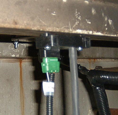
17 Below typical ECT installation at the rear of the block under the intake manifold. ECT needs to have constant flow of coolant on the sensor. Distributor module connections. Pink 12v white to coil neg. 17
18 Component Parts and Part Numbers Harness * 8510 ECM 7203 IAT 7303 ECT 7302 MAP 7300 O2 (Heated) 7301H3 TPS 7306 IAC 7309 Throttle body 7610 Injector 7660 Flange Gasket 7621 Fuel Pressure Regulator 7615 Fuel Pump 7703 Fuel Pump Ground wire harness 8500gnd Fuel Pump Hold Down Clamp 7703-cl Relay 7311h CE Light 7313 Low Fuel Light 7315 Fuse Link 7314 Fuel Filter G7333 Distributor 7815 Distributor Cap 7815-cap Distributor Rotor 7815-rot Oil Pressure Sender 7312 Fuel Level Sender 7316 Distributor Module 7820 OBDII Diagnostic Cable 8500OBDII * Base system 18
19 Troubleshooting your TBI Fuel Injection System Quick Troubleshooting Guide Connect Scan tool to the engine: Verify proper value of each sensor with Key on Engine Off. TPS 0% MAP dependent on altitude, will be less at high altitude. ECT consistent with engine temperature whether cold or warm IAT ambient temperature or higher If any of the above sensors are broadcasting default values work to that problem Default values are as follows: TPS 10% MAP 40 IAT & ECT 77 deg. F or 25 deg. C. If engine cranks and will not start unplug the connector from the TPS and attempt to start. If engine starts repair TPS circuit. If all the above checks are OK, install fuel pressure gauge. Turn key on and observe fuel pressure. Fuel pump should cycle on and then off and pressure should be between psi. If fuel pump does not turn on or pump does not provide full pressure repair fuel system If pump cycles on and off, determine if pump comes back on when the engine is cranked. Fuel pump should come back on when engine is cranked. Verify that fuel pressure registers between with the engine running and that the pressure rises with a rapid movement of the throttle. Repair fuel system if pressures are not in line or pressure drops on acceleration. When all of these checks have been made continue to step by step guide to further diagnose operational issues. Troubleshooting guide Most of the problems encountered while installing your fuel injection system or after a time of operation are very simple. If your check engine light is on you more than likely have a hard fault meaning something is grounded out, unplugged, operating out of range or has gone bad. See below for how to determine what the fault may be and code definitions. With the addition of Fuel Injection to your engine it is important to remember that the basics are still there, necessary and have not changed. Batteries must be fully charged, charging systems fully operational, the ignition system is fully operational and the integrity of the engine is intact. All of these items are common to an engine and need to be in full operational condition regardless of the fuel system that has been added to your engine. 19
20 The ALDL connector allows for full diagnostics of your unit If you have installed a Fuel Injection system in your vehicle and are having some initial issues here is a quick checklist to work from to get you started. Pink Ignition wire MUST be connected to 12 volt switched ignition that receives power during crank and key on. 1. Check to make sure your check engine light is not on, or that it is on with the key on but the engine is not running. 2. Make sure that the red battery wire is connected to a battery source (It is highly recommended that this wire is connected directly to the battery) and the pink wire is connected to an ignition 1 source. If your ignition wire is not connected to an ignition 1 source your ECM will not be powered while cranking the engine. 3. Check that the ground wire is securely fastened to the block and that the interface between the block and the terminal is clean. 4. Ensure that there are NO vacuum leaks. 5. Ensure that your MAP sensor is connected to a full manifold vacuum source and not a ported source. 6. Set the ignition timing correctly making sure that you have the engine fully warmed up and operating less than 800 RPM s. 7. Ensure that you have full manifold vacuum routed to your fuel pressure regulator and there are no vacuum leaks with this connection. 8. Check your fuel pressure to ensure that you are providing the proper pressure to the system. Fuel Pressure is critical for proper operation. Fuel tank must be free from debris and fuel pressure needs to be constant and consistent. Some aftermarket high density fuel filters can cause a large drop in fuel pressure under load and are not recommended for use with your system. If you are using one of these types of filters insure that you have proper fuel pressure during all modes of operation. 99% of all issues are usually taken care of with one or more of these 8 steps of diagnosis. First and foremost the engine and fuel injection system must be free of vacuum leaks. Vacuum leaks are the leading cause of installation issues with your fuel injection system. Check all sources of potential vacuum leaks including components not related to the fuel injection system. There are instances where the vacuum leak is coming from the governor to manifold mating surface. There are two bolts which bolt the manifold together that in some instances do not allow the governor to seal to the intake manifold. In some instances it is necessary to seal these with silicone to provide a positive seal. Another common issue is a lack of good grounding. Many issues have been resolved simply by making sure that the ground path is secure and clean. 20
21 Fuel System Checks Fuel Pressure is critical to the operation of a fuel injection system. Always check to insure that you have the proper fuel pressure. Fuel pressure should vary between about PSI. At idle the fuel injection system is typically around psi. Higher pressure than 55 psi indicates that there is an issue with the installation. Many times this is due to kinked fuel lines, improper routing of the return line and/or fuel line restrictions. (See Part 3 of Troubleshooting guide #3) Many fuel tanks hav e fittings on them which are used for a fuel tank vent. These fittings are not suitable to use as a return line because they have a restriction in them and restrict the flow of fuel back to the tank. If you have installed your return line to a vent line you will need to route the return line in a different fashion. Fuel pressure on your Gen II TBI unit should vary between psi based on the amount of vacuum on the fuel pressure regulator and stay constant under all throttle conditions. There should be an increase in pressure from idle to WOT operation of the TBI unit. A pressure drop under this operation indicates a restriction or issue with the fuel delivery system. With retrofit fuel injection systems many times we are drawing fuel from gas tanks that are many years old; hence many years have passed where contamination can settle into the fuel tank. The electric fuel pump installed for a fuel injection system will drawing a greater volume of fuel from your tank than your old system did. If there are any contaminants in the tank this many times will plug up or greatly restrict the flow of fuel to the system causing many issues. Step by Step Troubleshooting guide. Your fuel injection system has been pre calibrated to your particular vehicle. As long as the information about your engine was correctly stated, the system as received will provide many years of trouble free use. However from time to time problems are encountered with your fuel injection system. Here are a few commonly asked questions about fuel injection problems. Match the issue # with the chart below for an explanation of the issue and use the troubleshooting fault tree. Use of this section may require a digital voltmeter, test light, fuel pressure gauge, timing light, tachometer and/or a diagnostic scan tool. If you are familiar with vehicles and how they are serviced you should be able to work through this section with no issues. In many instances you may want to have a professional automotive technician familiar with fuel injection repair to help you. 1. My engine cranks but will not start. 2. My engine is running to lean, or is backfiring on acceleration. 3. My engine is running rich. 4. I do not seem to have as much power as I should. 5. I am getting a sag when I accelerate. 6. My engine takes longer to start than I think it should. 7. The fuel pump is not coming on when I first turn the key on. 8. The RPM on my engine does not come down when I come to an idle. 9. I am not getting as good of fuel economy as I think I should. 10.The engine is revving up and down when I come down to an idle. There is a large sucking sound coming from the throttle body when it 21
22 is warmed up. My engine stalls or almost stalls when I come down to an idle. 11. The engine stalls coming to an idle. 12. My fuel pump is real noisy. 13. My check engine light does not come on when I turn the key on. 14.My check engine light is on when the engine is running. 15. Engine shuts down and sometimes restarts and sometimes it doesn t. 1. Engine cranks but will not start. There is an assumption that the battery is at a full state of charge, the fuel tank has fuel in it and that all sensors are correctly connected and there are no trouble codes in the ECM. 1. Does the injector spray fuel when cranking the engine? Yes Go to step 2. No Disconnect the TPS sensor and determine if the vehicle starts, injector sprays. If engine starts or injector sprays, repair TPS circuit. If injector does not spray move to the next NO step. No - Remove the injector connector from the injector. With a voltmeter or test light measure the voltage or validate power to the pink wire of the connector with the key on. Yes Pink wire has voltage, go to step 1a. No There is no power getting to the system. Check for proper connection to the battery, fuses are good, relays have been connected and seated properly. Correct the power issue; if there is still no fuel spray when cranking the engine after this has been corrected go to step 1a. 1a. With the voltmeter or test light still connected crank the engine and verify voltage to the pink wire on the injector connector. Results: 0 volts or the light goes out when cranking the engine. The primary (pink) ignition wire is incorrectly connected to the vehicle. This is to be an ignition 1 (ING1) source which is power in both the key run and crank position. Correct the connection of this wire and verify voltage to the pink wire on the injector connector. Test again for fuel spray during crank. If the engine still cranks, is spraying fuel, but will not start go to step 2. Low volts, < 8 This is an indication of either a battery in a state of very low charge, a bad battery or too much resistance in the system. -record the battery voltage while cranking at the battery. -record the voltage at the pink wire of the injector connector while cranking the engine. -compare these two voltages, they should be within.2 (2/10) volts of each other. If these voltages are greater than.2 there is a bad connection or too much resistance in the wire feeding the ECM. -Correct the issue with low voltage. If cranking voltage is above 9 volts while cranking and there is still no fuel spraying the issue is in the fuel delivery system. 9 volts or higher this is normal cranking voltage. If there is no fuel spraying while cranking the issue is in the fuel delivery system or ignition system Trouble shoot the fuel system for improper operation (See Fuel System checks at the beginning of this guide). Troubleshoot ignition system, go to 1b. 22
23 1b. Your TBI fuel injection system fueling is triggered from the ignition system. It is assumed that the coil is operational, a 12 volt ignition 1 (IGN1) source is connected to the positive terminal of the coil. Remove plug wire and check for spark while cranking. No Spark Repair ignition system. Has spark Insure wire continuity between the ECM and the distributor. If fuel is still not spraying go to fuel system troubleshooting before replacing any components. If all wires are in tact and routed correctly and all fuel system checks are correct, replace distributor module. 2. Perform the fuel system checks found at the beginning of this troubleshooting Guide. If the fuel pressure and fuel system are operating as required Insure that the check engine light is on with the key on but the engine not running and there are no stored codes. If you have installed a new distributor, removed the distributor for any reason your ignition timing may be off too much to operate the engine properly. Disconnect the connector from the injector and set the ignition timing to its proper setting while cranking the engine. Assumption here also is that the timing mark on the balancer is lined up with TDC of #1 cylinder and that the distributor is seated properly and not 180 degrees off. If all of this checks OK go to step Measure the voltage on the throttle position sensor. If using a scan tool you can read TPS, if not measure the voltage. To measure the throttle position voltage check between the brown wire and the black/white striped wire on the TPS with the TPS still connected and the key on. DO NOT PUNCTURE THE WIRES to measure this voltage and only use a digital voltmeter. Voltage can be measured by back probing the TPS connector between these wires either with a thin paper clip or appropriate tool used for this type of measurement. Voltage should be between.5 volts and.7 volts. If you have gone through all of the above procedures and the engine still will not start you will need to call tech support. When you call tech support you will need to have the following information available. Fuel pressure at the inlet of the TBI unit Return line fuel pressure Voltage measured at the battery while cranking Voltage measured at the pink wire on the injector while cranking Voltage measured at the TPS sensor key on engine off Codes stored in the ECM Any information that you feel is important for diagnosing the issue at hand. 2. My engine is running to lean, or is backfiring on acceleration. Assumption here is that all plug wires are installed properly, the secondary ignition system (plug wires, coil, cap and rotor) is in good operating order and the engine is in good order. Perform fuel system checks found at the beginning of this guide and make any corrections as necessary. 23
24 Check initial ignition timing again. If the timing is OK check to insure that the timing is advancing as it should with throttle lever actuation. If the fuel system checks performed are OK and the initial ignition timing is OK you will need to call tech support. If you have gone through all of the above procedures and the engine is still running lean or is backfiring on acceleration you will need to call tech support. In many cases the specifications of the engine are different than what was originally discussed or assumed. When you call tech support you will need to have the following information available. Fuel pressure at idle Fuel pressure while briefly accelerating the engine to WOT Return line fuel pressure Voltage measured at the battery while running Engine operational temperature Initial ignition timing Timing at 2000 RPM Any information that you feel is important for diagnosing the issue at hand. 3. Engine runs too rich. Check for vacuum leaks and insure that all vacuum leaks are corrected and sealed. If the engine is also running at a higher than expected idle this is a good indication of a vacuum leak as well. 1. Is the vacuum line to the MAP sensor securely fastened to both the MAP sensor port and a full manifold vacuum port on the intake manifold? Yes, If engine is still running rich go to step 2. No Repair leak, kink or routing, is engine still running rich? If yes go to step Is the MAP sensor connected to a full manifold vacuum port? Yes If engine is still running rich go to step 3. No Correct the vacuum source issue, if the engine is still running rich go to step Is the fuel pressure measured at psi while running? Yes If the engine is still running rich go to step 4. No Is the return line connected to an unrestricted return port on the fuel tank? Many fuel tanks have a port on the fuel tank that is for a fuel vent. These ports are not adequate for a fuel return. There is an orifice in these ports that will restrict the flow of fuel. Check that you have not used a vent port for the fuel return line. No Go to step 3a. Yes Fuel is being returned to a vent line. Re-route fuel return line to a non 24
25 orificed port or fabricate a free flowing return line port to the fuel tank or fuel return. If still running rich go to step 3a. 3a. Measure return line fuel pressure. This pressure should be less than 3 psi, if not there is a restriction in the return fuel line. If return fuel line pressure is less than 3 psi and the engine is still running rich go to step 4. If return line pressure is not less than 3 psi there is a restriction in the fuel line Find and repair the restriction until the fuel pressure on the return line is less than 3psi. In some cases this requires a larger diameter fuel return line. Go to step 3b to help determine root cause of increased return line pressure. 3b. Remove the fuel return line and attach a length of rubber hose of sufficient length to run into an approved gasoline container. Run engine and recheck fuel pressure on both the feed side and the return side. If both sides are within the above ranges there is a restriction in the fuel delivery system that needs to be repaired. 4. Does the engine have a fully operational thermostat? Yes insure that the engine will reach 190 deg. in a reasonable time, go to step 5. No Install new thermostat, proper size thermostat will be or 180 degree thermostat is not acceptable for this application and will not comply with AFI warranty or emissions requirements. If still running rich go to step Is the coolant sensor installed in a portion of the engine or the cylinder block which provides a constant flow of coolant over the tip of the sensor? Yes Go to step 6. No Reinstall the coolant sensor in a different location to insure constant flow of coolant over the sensor. If still running rich go to step Is the charging system operating properly and is the voltage measured at the battery and the injector 13 volts or higher with the engine running? Yes Go to step 7. No Repair charging system. Note the discussion about older style AC Delco single wire alternators. If still running rich after reparing go to step If you have gone through all of the above procedures and the engine is still running rich you will need to call tech support. In many cases the specifications of the engine are different than what was originally discussed or assumed. When you call tech support you will need to have the following information available. Fuel pressure at idle Return line fuel pressure Voltage measured at the battery while running Voltage measured at the pink wire on the injector while cranking. Engine RPM at start up idle on a cold start Engine RPM at idle with stabilized temperature Engine operational temperature Initial ignition timing Any information that you feel is important for diagnosing the issue at hand. 25
26 4. I do not seem to have as much power as I should. Verify that you have set your timing properly, timing should be set to 12 deg. BTDC with the engine fully warmed up and RPM below 800. Verify that the timing mark for TDC of #1 cylinder that is being used to set the timing lines up properly with TDC of #1 cylinder (#1 piston at TDC with spark plug removed). Ensure that your plug wires are properly connected with the correct firing order. Your fuel pressure may be insufficient; see fuel system checks at the beginning of this guide. Verify that there are no vacuum leaks and that the MAP sensor is properly connected. 5. I am getting a sag when I accelerate. Insure that the MAP sensor and TPS sensor are working properly with scan tool. Default values for MAP and TPS are a single value and can cause a sag if not operating properly. Timing is a critical issue with sags. Verify that your timing is correctly. see #4 also. Fuel pressure is not adequate for proper operation, make sure that there is no contamination in the tank or your fuel filter is plugged. (See Fuel System check above). A plugged fuel filter may be an indication of a contaminated tank. Bad ground to the block, insure that the surface that you are making the connection to on the block is clean and making a positive connection. Your O2 sensor may be contaminated, bad or not properly installed in the exhaust. You may have left out some of the important specifications for the proper calibration chip to be made. If you have gone through all of the above procedures and the engine is still sagging on acceleration you will need to call tech support. In many cases the specifications of the engine are different than what was originally discussed or assumed. When you call tech support you will need to have the following information available. Fuel pressure at idle Fuel pressure when throttle is blipped to WOT Return line fuel pressure Voltage measured at the battery while running Voltage measured at the pink wire on the injector while cranking. Engine RPM at start up idle on a cold start Engine RPM at idle with stabilized temperature Engine operational temperature 26
27 Initial ignition timing Any information that you feel is important for diagnosing the issue at hand. 6. My engine takes longer to start than I think it should. Check for vacuum leaks, this is the most common cause. Make sure that your timing is set correctly; see Troubleshooting point #4. Fuel pressure is not adequate for proper operation. See Fuel System Checks at the beginning of this guide. Fuel pump relay is not coming on or is faulty. Check that the MAP sensor is properly connected to a full manifold vacuum source. Ensure that the vacuum source to your MAP sensor is free from restrictions and has a secure connection. Throttle plates are not adjusted properly not allowing an adequate amount of air for starting the engine. Go to Troubleshooting guide #10 and verify the adjustment. Throttle position sensor is out of adjustment or faulty. Throttle position voltage with throttle fully closed with the key on should be.5 volts +.2 volts. If you have gone through all of the above procedures and the engine is still sagging on acceleration you will need to call tech support. In many cases the specifications of the engine are different than what was originally discussed or assumed. When you call tech support you will need to have the following information available. Fuel pressure at idle Voltage measured at the battery while running Voltage measured at the pink wire on the injector while cranking Voltage measured between the black wire and brown wire on the TPS with the key on engine not running Engine RPM at start up idle on a cold start Engine RPM at idle with stabilized temperature Engine RPM at idle with IAC fully blocked off. IAC counts at stabilized idle in drive if using a scan tool Engine operational temperature Initial ignition timing Any information that you feel is important for diagnosing the issue at hand. 7. The fuel pump is not coming on when I first turn the key on. Is the check engine light on with the key on engine off? (Assumes check engine light is connected properly, see installation instructions to verify check engine light installation) 27
28 Yes - Go to step 1. No Check for proper installation of check engine light. a. Check fuses to insure that they are not blown. If fuses are OK go to b. b. Check voltage at check engine light, if 12 volt are not present the check engine light is not connected properly. If 12 volts are present either the ECM is not powered properly or is defective. 1. Insure that the IGN1 wire is not connected to a battery feed. a. Check pink wire to the power relay and/or the pink wire powering up the injector(s) to insure there is no voltage with the key off. If voltage is present with the key off the pink wire is not properly connected or the power relay is bad. a. Check fuel pump relay for proper operation. Turn ignition off for at least 15 seconds. Connect an ohmmeter or test light to the blue wire at the fuel pump relay. Turn ignition on, a ground signal should be present at this wire for the first 2 or 3 seconds after turning on the ignition switch. If ground is not present either the ECM is not powered or grounded properly or the ECM is faulty. If ground is present check for voltage at the fuel pump with the same type of operation. If voltage is not present at the fuel pump check the wiring, if wires appear to be OK replace the fuel pump relay. If voltage is present verify the ground for the fuel pump is sufficient and securely fastened. If fuel pump ground is OK the fuel pump is defective. If you have gone through all of the above procedures and the fuel pump is still not coming on when you turn the key on you will need to call tech support. When you call tech support you will need to have the following information available. Voltage measured at the check engine light with key on engine off Voltage measured at the pink wire on the injector while cranking Voltage measured at the pink wire on the injector with the key off Ohms measured at the blue wire at the fuel pump relay at first 3 seconds of the key on Voltage measured at the pink wire to the fuel pump at the first 3 seconds of the key on Voltage measured with voltmeter between the black wire and pink wire on the fuel pump for the first 3 seconds of the key on Any information that you feel is important for diagnosing the issue at hand. 8. The RPM on my engine does not come down when I come to an idle. More than likely you have a large vacuum leak, verify that your system is free from vacuum leaks. Check that all non used vacuum ports are plugged. Your ignition wire is connected to a battery source and not an ignition 1 source. The engine has not come to full operating temperature as of yet. 28
9415 W. Ridge Rd. Elsie, MI
 9415 W. Ridge Rd. Elsie, MI 48831 248-393-1621 989-862-4163 TBI INSTALLATION INSTRUCTIONS Congratulations on the purchase of your Affordable Fuel Injection TBI system. We are confident that this purchase
TBI INSTALLATION INSTRUCTIONS for Zenith Stromberg, SU, and Hitachi side draft carbs
 TBI INSTALLATION INSTRUCTIONS for Zenith Stromberg, SU, and Hitachi side draft carbs Congratulations on the purchase of your Patton Machine / Affordable Fuel Injection TBI system. We are confident that
HOWELL INSTALLATION MANUAL. Throttle Body Fuel Injection Harness
 HOWELL ENGINE DEVELOPMENTS, INC. FUEL INJECTION APPLICATIONS INSTALLATION MANUAL Throttle Body Fuel Injection Harness Howell Engine Developments, Inc. 6201 Industrial Way Marine City, MI 48039 Phone: 810-765-5100
Fuel Metering System Component Description
 1999 Chevrolet/Geo Tahoe - 4WD Fuel Metering System Component Description Purpose The function of the fuel metering system is to deliver the correct amount of fuel to the engine under all operating conditions.
1998 ENGINE PERFORMANCE. General Motors Corp. - Basic Diagnostic Procedures - 5.7L
 INTRODUCTION 1998 ENGINE PERFORMANCE General Motors Corp. - Basic Diagnostic Procedures - 5.7L The following diagnostic steps will help prevent overlooking a simple problem. This is also where to begin
DTC P0172 Fuel Trim System Rich
 Page 1 of 6 1997 Chevrolet Cavalier Cavalier, Sunfire (VIN J) Service Manual Document ID: 47788 DTC P0172 Fuel Trim System Rich System Description A Closed Loop air/fuel metering system is used to provide
Propane and Gasoline Electronic Fuel Injection
 Zenith Electronic Engine Management System Propane and Gasoline Electronic Fuel Injection 1 Slide 1 2 Slide 2 Home Page System Advantages Block Diagram, Electronic Control Unit Inputs Output Controls System
INTAKE SWAP INSTRUCTION MANUAL 1.Items to pick up before you begin:
 INTAKE SWAP INSTRUCTION MANUAL 1.Items to pick up before you begin: Someone to lend you a hand for about 10 minutes Intake gasket set that pertains to your year of engine Coil of your choice Spark plugs
Powertrain DTC Summaries EOBD
 Powertrain DTC Summaries Quick Reference Diagnostic Guide Jaguar X-TYPE 2.0 L 2002.25 Model Year Refer to page 2 for important information regarding the use of Powertrain DTC Summaries. Jaguar X-TYPE 2.0
4.0L CEC SYSTEM Jeep Cherokee DESCRIPTION OPERATION FUEL CONTROL DATA SENSORS & SWITCHES
 4.0L CEC SYSTEM 1988 Jeep Cherokee 1988 COMPUTERIZED ENGINE Controls ENGINE CONTROL SYSTEM JEEP 4.0L MPFI 6-CYLINDER Cherokee, Comanche & Wagoneer DESCRIPTION The 4.0L engine control system controls engine
G - TESTS W/CODES - 2.2L
 G - TESTS W/CODES - 2.2L 1994 Toyota Celica 1994 ENGINE PERFORMANCE Toyota 2.2L Self-Diagnostics Celica INTRODUCTION If no faults were found while performing F - BASIC TESTING, proceed with self-diagnostics.
2002 ENGINE PERFORMANCE. Self-Diagnostics - RAV4. Before performing testing procedures, check for any related Technical Service Bulletins (TSBs).
.") 2002 ENGINE PERFORMANCE Self-Diagnostics - RAV4 INTRODUCTION NOTE: Before performing testing procedures, check for any related Technical Service Bulletins (TSBs). To properly diagnosis and repair this
2002 ENGINE PERFORMANCE Self-Diagnostics - RAV4 INTRODUCTION NOTE: Before performing testing procedures, check for any related Technical Service Bulletins (TSBs). To properly diagnosis and repair this
CAUTION: READ INSTRUCTIONS CAREFULLY BEFORE STARTING INSTALLATION
 V-Twin MFG. VT No. 32-9500 V-TECH 1 IGNITION KIT, SINGLE FIRE FITS EV SHOVEL, XL THRU 1997 VT No. 32-9503 V-TECH 1 IGNITION KIT, SINGLE FIRE FITS EV, SHOVEL, XL, WITH COIL AND WIRES This is a custom application
 Page 1 of 6 NO START - ENGINE CRANKS OKAY General Inspection 1. Ensure proper starting procedure is being used. 2. Visually check vacuum hoses for splits, kinks and improper connections. See underhood
FUEL INJECTION SYSTEM - MULTI-POINT
 FUEL INJECTION SYSTEM - MULTI-POINT 1988 Jeep Cherokee 1988 Electronic Fuel Injection JEEP MULTI-POINT 4.0L Cherokee, Comanche, Wagoneer DESCRIPTION The Multi-Point Electronic Fuel Injection (EFI) system
H - TESTS W/O CODES Volvo 960 INTRODUCTION SYMPTOMS SYMPTOM DIAGNOSIS ENGINE PERFORMANCE Volvo Trouble Shooting - No Codes
 H - TESTS W/O CODES 1994 Volvo 960 1994 ENGINE PERFORMANCE Volvo Trouble Shooting - No Codes Volvo; 850, 940, 960 INTRODUCTION Before diagnosing symptoms or intermittent faults, perform steps in appropriate
HOWELL INSTALLATION MANUAL. Tuned Port Or LT-1 Fuel Injection Harness ( )
") HOWELL ENGINE DEVELOPMENTS, INC. FUEL INJECTION APPLICATIONS INSTALLATION MANUAL Tuned Port Or LT-1 Fuel Injection Harness (1985-1992) Howell Engine Developments, Inc. 6201 Industrial Way Marine City,
HOWELL ENGINE DEVELOPMENTS, INC. FUEL INJECTION APPLICATIONS INSTALLATION MANUAL Tuned Port Or LT-1 Fuel Injection Harness (1985-1992) Howell Engine Developments, Inc. 6201 Industrial Way Marine City,
Honda Accord/Prelude
 Honda Accord/Prelude 1984-1995 In Tank Fuel Pumps TEST 1. Turn the ignition OFF. 2. On the Accord, remove the screws securing the underdash fuse box to its mount. Remove the fuel cut off relay from the
H - TESTS W/O CODES INTRODUCTION SYMPTOMS
 H - TESTS W/O CODES 1995 Volvo 850 1995 ENGINE PERFORMANCE Volvo - Trouble Shooting - No Codes 850 INTRODUCTION Before diagnosing symptoms or intermittent faults, perform steps in the F - BASIC TESTING
IGNITION TIMING (GASOLINE)
") IGNITION TIMING (GASOLINE) 4-CYLINDER IGNITION TIMING 2.5L (VIN E) 1. Set parking brake, block drive wheels and place transmission in Neutral or Park. Warm engine to normal operating temperature. Turn
IGNITION TIMING (GASOLINE) 4-CYLINDER IGNITION TIMING 2.5L (VIN E) 1. Set parking brake, block drive wheels and place transmission in Neutral or Park. Warm engine to normal operating temperature. Turn
INSTALLATION OF HOWELL ENGINE DEVELOPMENTS HIGH PERFORMANCE 2 & 4 BBL THROTTLE BODY FUEL INJECTION ON ENGINES ORIGINALLY EQUIPPED WITH CARBURETORS
 4 Barrel TBI installation Page 1 INSTALLATION OF HOWELL ENGINE DEVELOPMENTS HIGH PERFORMANCE 2 & 4 BBL THROTTLE BODY FUEL INJECTION ON ENGINES ORIGINALLY EQUIPPED WITH CARBURETORS THIS SYSTEM IS BASED
Powertrain DTC Summaries OBD II
 Powertrain DTC Summaries Quick Reference Diagnostic Guide Jaguar X-TYPE 2.5L and 3.0L 2002 Model Year Revised January, 2002: P0706, P0731, P0732, P0733, P0734, P0735, P0740, P1780 POSSIBLE CAUSES Revised
MALLORY FIRESTORM CD MULTI COIL HARDWARE INSTALLATION - PN 69050S / 69050R
 FORM 69050S/R MALLORY FIRESTORM CD MULTI COIL HARDWARE INSTALLATION - PN 69050S / 69050R To ensure you are using the most current instruction sheet, please visit www.malloryfirestorm.com. CAUTION! The
DESCRIPTION Chevrolet Chevy Van 5.7L Eng G20. Service Manual: FUEL INJECTION SYSTEM - TBI
 Service Manual: FUEL INJECTION SYSTEM - TBI DESCRIPTION 1989 Chevrolet Chevy Van 5.7L Eng G20 The throttle body fuel injection system consists of 7 major sub-assemblies: fuel supply system, throttle body
C FORD F250 / F L POWERSTROKE DIESEL WITH AUTOMATIC TRANSMISSIONS ONLY
 EXHAUST BRAKES C40019 1999-2003 FORD F250 / F350 7.3L POWERSTROKE DIESEL WITH AUTOMATIC TRANSMISSIONS ONLY Getting Started Thank you and congratulations on your purchase of a Pacbrake exhaust retarder.
1993 ENGINE PERFORMANCE Volkswagen System & Component Testing - Digifant. EuroVan
 Article Text ARTICLE BEGINNING 1993 ENGINE PERFORMANCE Volkswagen System & Component Testing - Digifant EuroVan INTRODUCTION Since many computer-controlled and monitored components set a trouble code if
F - BASIC TESTING Infiniti G20 INTRODUCTION PRELIMINARY INSPECTION & ADJUSTMENTS VISUAL INSPECTION MECHANICAL INSPECTION
 F - BASIC TESTING 1992 Infiniti G20 1992 ENGINE PERFORMANCE Infiniti Basic Diagnostic Procedures G20, M30, Q45 INTRODUCTION The following diagnostic steps will help prevent overlooking a simple problem.
Powertrain DTC Summaries EOBD
 Powertrain DTC Summaries Quick Reference Diagnostic Guide Jaguar S-TYPE V6, V8 N/A and V8 SC 2002.5 Model Year Refer to pages 2 9 for important information regarding the use of Powertrain DTC Summaries.
Typical Install Instructions
 Typical Install Instructions Read & understand all steps of these instructions before beginning this installation. WEBER Conversion Kit, VW T-1/2, up to 1835cc 32 / 36 DFEV Weber Carburetor These instructions
TELORVEK TPI WIRING INSTRUCTIONS FOR TH-90 (95 CK TRUCK) 4.3,5.0,5.7,7.4 TBI Fuel Injection System W/4L60-E or 4L80-E Transmission
 4.3,5.0,5.7,7.4 TBI Fuel Injection System W/4L60-E or 4L80-E Transmission") Page #1 TELORVEK TPI WIRING INSTRUCTIONS FOR TH-90 (95 CK TRUCK) 4.3,5.0,5.7,7.4 TBI Fuel Injection System W/4L60-E or 4L80-E Transmission Thank you for purchasing the absolute finest of wiring kits for
Page #1 TELORVEK TPI WIRING INSTRUCTIONS FOR TH-90 (95 CK TRUCK) 4.3,5.0,5.7,7.4 TBI Fuel Injection System W/4L60-E or 4L80-E Transmission Thank you for purchasing the absolute finest of wiring kits for
BASIC DIAGNOSTIC PROCEDURES
 BASIC DIAGNOSTIC PROCEDURES 2001 Chevrolet Camaro 2001 ENGINE PERFORMANCE Basic Diagnostic Procedures - Cars Except Metro & Prizm MODEL IDENTIFICATION MODEL IDENTIFICATION Body Code (1) Model C... Park
C40008 & C40009 EXHAUST BRAKES
 EXHAUST BRAKES C40008 & C40009 1995 2003 Ford F250 / F350 7.3 L Powerstroke Diesel with manual transmissions 1995 1998 Ford F250 / F350 7.3 L Powerstroke Diesel with automatic transmission* *Requires the
DTC P0171, P0172, P0174, or P0175
 Page 1 of 6 2009 Pontiac G8 G8 Service Manual Document ID: 2076050 DTC P0171, P0172, P0174, or P0175 Diagnostic Instructions Perform the Diagnostic System Check - Vehicle prior to using this diagnostic
Catalytic Failures. Engine running too hot.
 Catalytic Failures It is not uncommon for technicians to misdiagnose a driveability or emissions issue by blaming the converter. In many cases, it s not the converter s fault, but rather one of the engine
2002 Buick Rendezvous - AWD
 2002 Buick Rendezvous - AWD DTC P0410 Description The control module activates the secondary air injection (AIR) system by grounding both the pump relay and the vacuum control solenoid control circuits.
MALLORY FIRESTORM CD MULTI COIL HARDWARE INSTALLATION - PN 69150C / 69150R
 FORM 69150C/R MALLORY FIRESTORM CD MULTI COIL HARDWARE INSTALLATION - PN 69150C / 69150R To ensure you are using the most current instruction sheet, please visit www.malloryfirestorm.com. CAUTION! The
ATASA 5 th. ATASA 5 TH Study Guide Chapter 31 Pages EFI Diagnosis & Service 47 Points. Please Read The Summary
 ATASA 5 TH Study Guide Chapter 31 Pages 922 948 47 Points Please Read The Summary 1. Troubleshooting EFI systems requires step by step test procedures mostly due to the many interrelated components and
Getting to know your Powertrain Control Module (PCM)
") Thank-you for choosing Swap Specialties and Performance for your LS project needs. Expect everything to be the highest of quality, craftsmanship, and detail. Every product is 100% tested. Please follow
Thank-you for choosing Swap Specialties and Performance for your LS project needs. Expect everything to be the highest of quality, craftsmanship, and detail. Every product is 100% tested. Please follow
Part Number: TDZ-75SD / BRONCO-75SD
 Ford 5.0 EFI Harness Installation Manual For Classic Fords & Mustangs and Early Broncos Part Number: TDZ-75SD / BRONCO-75SD Ron Francis Wiring & The Detail Zone 200 Keystone Rd. Chester, PA 19013 800-292-1940
TELORVEK II RJ-32 Big Block RamJet Fuel Injection System
 Page #1 TELORVEK II RJ-32 Big Block RamJet Fuel Injection System This wiring system is compatible with the GM Performance part big block Ramjet 502 engine. The harness is designed to dress up the appearance
ELECTRONIC FUEL INJECTION
 Table of Contents ELECTRONIC FUEL INJECTION Section 3B - Troubleshooting and Diagnostics TROUBLESHOOTING AND DIAGNOSTICS Specifications........................... 3B-1 Special Tools...........................
F - BASIC TESTING Toyota Celica INTRODUCTION PRELIMINARY INSPECTION & ADJUSTMENTS VISUAL INSPECTION MECHANICAL INSPECTION
 F - BASIC TESTING 1994 Toyota Celica 1994 ENGINE PERFORMANCE Toyota 4-Cylinder Basic Diagnostic Procedures Celica INTRODUCTION The following diagnostic steps will help prevent overlooking a simple problem.
Engine Cranks But Does Not Run
 Page 1 of 5 2000 GMC Truck GMC K Sierra - 4WD Sierra, Silverado, Suburban, Tahoe, Yukon (VIN C/K) Service Manual Engine Engine Controls - 4.8L, 5.3L, and 6.0L Diagnostic Information and Procedures Engine
WEBER CARBURETOR TROUBLESHOOTING GUIDE
 This guide is to help pinpoint problems by diagnosing engine symptoms associated with specific vehicle operating conditions. The chart will guide you step by step to help correct these problems. For successful
Subject Underhood G System Error Codes and Symptoms System or Parts affected
 System or Parts affected Index Underhood70G (V90Gxxx) System or Parts affected... 1 Overview... 1 Identifying your System... 1 Retrieving Logged Error Messages... 1 Error Messages... 3 Error Message Table...
H - TESTS W/O CODES Nissan 240SX INTRODUCTION TROUBLE SHOOTING SYMPTOMS DIAGNOSIS WILL NOT START
 H - TESTS W/O CODES 1990 Nissan 240SX 1990 ENGINE PERFORMANCE Trouble Shooting - No Codes Nissan; 240SX, Axxess, Maxima, Pathfinder, Pickup, Pulsar, Sentra, Van, INTRODUCTION Before diagnosing symptoms
MAKE OF AUTOMOBILE: ENGINE SET NUMBER 366/
 MAKE OF AUTOMOBILE: TYPE: SORENTO PISTON DISPLACEMENT: 3300 NUMBER OF VALVES: 24 ENGINE NUMBER: G6DB TRANSMISSION TYPE ( MT / AT ) MT VEHICLE CATEGORIES M or N M TYPE VSI INJECTOR ( NUMBER + COLOR ) 180/30340
Diagnostic Trouble Code (DTC) Root Cause. for Omnitek ECM 64A/66A/88A. & Remedial Action
 Root Cause. for Omnitek ECM 64A/66A/88A. & Remedial Action") Diagnostic Trouble Code (DTC) Root Cause & Remedial Action for Omnitek ECM 64A/66A/88A Omnitek Engineering Corp. 1945 S Rancho Santa Fe Rd. San Marcos, CA 92078 Tel. 760-591-0089 - Fax. 760-591-0880 -
Diagnostic Trouble Code (DTC) Root Cause & Remedial Action for Omnitek ECM 64A/66A/88A Omnitek Engineering Corp. 1945 S Rancho Santa Fe Rd. San Marcos, CA 92078 Tel. 760-591-0089 - Fax. 760-591-0880 -
DO NOT adjust by-pass valve full-close screw. Adjustment is preset at factory.
 I - SYSTEM/COMPONENT TESTS Article Text 1993 Honda Prelude For Cadi Centre Nsk CA 95051 Copyright 1998 Mitchell Repair Information Company, LLC Sunday, July 08, 2001 11:31AM ARTICLE BEGINNING 1993 ENGINE
PRELIMINARY INSPECTION & ADJUSTMENTS
 PRELIMINARY INSPECTION & ADJUSTMENTS VISUAL INSPECTION Most driveability problems in the engine control system result from faulty wiring, poor electrical connections or leaking air and vacuum hose connections.
Fuel System Diagnosis
 1996 Chevrolet Impala Caprice, Impala, Roadmaster (VIN B) Service Manual Engine Engine Controls - 4.3L (Caprice Only) and 5.7L Diagnostic Information and Procedures Document ID: 37723 Fuel System Diagnosis
Powertrain DTC Summaries EOBD
 Powertrain DTC Summaries Quick Reference Diagnostic Guide Jaguar X-TYPE 2.5L and 3.0L 2001.5 Model Year Revised January, 2002: P0706, P0731, P0732, P0733, P0734, P0735, P0740, P1780 POSSIBLE CAUSES Revised
SYTY Trouble Code: ALDL INFORMATION
 SYTY Trouble Code: ALDL INFORMATION A -- Ground G -- Fuel Pump B -- Diagnostic Terminal H -- Brake Sense Speed Input F -- TCC M -- Serial Data (special tool needed - Do Not Use) For ECM Trouble Codes,
 Page 1 of 18 2004 PCED On Board Diagnostics SECTION 5: Pinpoint Tests Procedure revision date: 10/26/2007 H: Fuel Control H: Introduction H1 PERFORM THE KOER SELF-TEST Engine at normal operating temperature.
MAKE OF AUTOMOBILE: TYPE: V 70 PISTON DISPLACEMENT: 2521 NUMBER OF VALVES:
 MAKE OF AUTOMOBILE: TYPE: V 70 PISTON DISPLACEMENT: 2521 NUMBER OF VALVES: 20V ENGINE NUMBER: B5254T TRANSMISSION TYPE ( MT / AT ) AT VEHICLE CATEGORIES M or N PASSENGER CAR ( M ) TYPE VSI INJECTOR (COLOUR
MAKE OF AUTOMOBILE: PISTON DISPLACEMENT: 1600 NUMBER OF VALVES: 16
 MAKE OF AUTOMOBILE: TYPE: MERIVA PISTON DISPLACEMENT: 1600 NUMBER OF VALVES: 16 ENGINE NUMBER: Z16XEP TRANSMISSION TYPE ( MT / AT ) MT VEHICLE TYPE M TYPE VSI INJECTOR ( NUMBER + COLOR ) 180/30430 ORANGE
F - BASIC TESTING Nissan 240SX INTRODUCTION VISUAL INSPECTION COMPRESSION CHECK EXHAUST SYSTEM BACKPRESSURE CHECK
 F - BASIC TESTING 1990 Nissan 240SX 1990 ENGINE PERFORMANCE Nissan - Basic Diagnostic Procedures Nissan; Axxess, Maxima, Pathfinder, Pickup, Pulsar NX, Sentra, Stanza, Van, 240SX, 300ZX INTRODUCTION The
Fuel System Diagnosis
 Page 1 of 9 1999 Chevrolet Express Express, Savana (VIN G) Service Manual Engine Engine Controls - 5.0L and 5.7L Diagnostic Information and Procedures Document ID: 412957 Fuel System Diagnosis Circuit
Digifant Ignition Basics, Eurovan Or, what to look for if your 5 Cylinder Eurovan won t start due to no spark
 Digifant Ignition Basics, 1992-96 Eurovan Or, what to look for if your 5 Cylinder Eurovan won t start due to no spark The story: In the spring of 2007, I started to have hard starting issues with my 93
ARTICLE BEGINNING INTRODUCTION SELF-DIAGNOSTIC SYSTEM RETRIEVING DTCS ENGINE PERFORMANCE Volkswagen Self-Diagnostics - Gasoline
 Article Text ARTICLE BEGINNING 1996 ENGINE PERFORMANCE Volkswagen Self-Diagnostics - Gasoline Cabrio, Golf III, GTI, Jetta III, Passat INTRODUCTION If no faults were found while performing preliminary
MAKE OF AUTOMOBILE: MODEL YEAR: 2007 SYSTEM APPROVAL NUMBER ( R115 ) VSI-LPG 10 ENGINE SET NUMBER 364/
 VSI-LPG 10 ENGINE SET NUMBER 364/") MAKE OF AUTOMOBILE: TYPE: FABIA PISTON DISPLACEMENT: 1400 NUMBER OF VALVES: 16 ENGINE NUMBER: BUD TRANSMISSION TYPE ( MT / AT ) MT VEHICLE CATEGORIES M or N M TYPE VSI INJECTOR ( NUMBER + COLOR ) 180/30410
MAKE OF AUTOMOBILE: TYPE: FABIA PISTON DISPLACEMENT: 1400 NUMBER OF VALVES: 16 ENGINE NUMBER: BUD TRANSMISSION TYPE ( MT / AT ) MT VEHICLE CATEGORIES M or N M TYPE VSI INJECTOR ( NUMBER + COLOR ) 180/30410
INSTALLATION INSTRUCTIONS for HI-4 DUAL FIRE MOTORCYCLE IGNITION. Part Number INTRODUCTION REMOVAL OF POINTS IGNITION TO 1977 MODELS
 INSTALLATION INSTRUCTIONS for HI- DUAL FIRE MOTORCYCLE IGNITION Part Number -00 CAUTION: READ INSTRUCTIONS CAREFULLY BEFORE STARTING INSTALLATION INTRODUCTION The HI- ignition system is intended for use
Part #82064 Add-A-Stage EFI Nitrous System
 1 INSTRUCTIONS Part #82064 Add-A-Stage EFI Nitrous System Thank you for choosing products; we are proud to be your manufacturer of choice. Please read this instruction sheet carefully before beginning
SAISBM V36W Installation Instructions
 The Original Secondary Air Injection System Bypass Kit SAISBM V36W Installation Instructions All Applicable Toyota/Lexus Vehicles Introduction: The Secondary Air Injection System (SAIS) bypass module is
Code 32. Diagnostic Trouble Code 32
 Code 32 Diagnostic Trouble Code 32 EGR Solenoid Circuit CIRCUIT DESCRIPTION The ECM operates a solenoid to control the Exhaust Gas Recirculation (EGR) valve. This solenoid is normally close EGR valve.
A. Perform a vacuum gauge test to determine engine condition and performance.
 ENGINE REPAIR UNIT 2: ENGINE DIAGNOSIS, REMOVAL, AND INSTALLATION LESSON 2: ENGINE DIAGNOSTIC TESTS NOTE: Testing the engine s mechanical condition is required when the cause of a problem is not located
DTC P1415 Secondary Air Injection (AIR) System Bank 1
 System Bank 1") Page 1 of 5 2000 GMC Truck GMC K Sierra - 4WD Sierra, Silverado, Suburban, Tahoe, Yukon (VIN C/K) Service Manual Document ID: 546887 DTC P1415 Secondary Air Injection (AIR) System Bank 1 Circuit Description
Page 1 of 5 2000 GMC Truck GMC K Sierra - 4WD Sierra, Silverado, Suburban, Tahoe, Yukon (VIN C/K) Service Manual Document ID: 546887 DTC P1415 Secondary Air Injection (AIR) System Bank 1 Circuit Description
F - BASIC TESTING Article Text 1992 Dodge Colt For a a a a a Copyright 1998 Mitchell Repair Information Company, LLC Saturday, April 27, :48PM
 Article Text ARTICLE BEGINNING 1992 ENGINE PERFORMANCE Chrysler Motors/Mitsubishi Basic Diagnostic Procedures Chrysler Motors: Colt, Colt 200, Summit Mitsubishi: Mirage INTRODUCTION The following diagnostic
Chrysler Electronic Ignition System
 1 of 11 1/6/2010 11:02 PM Chrysler Electronic Ignition System Classic Winnebago's Post by: DaveVA78Chieftain on August 13, 2009, 10:15 PM Components The Chrysler Electronic Ignition System consists of
TELORVEK III. WIRING INSTRUCTIONS FOR LT-40 LT-1 Fuel Injection System
 TELORVEK III WIRING INSTRUCTIONS FOR LT-40 LT-1 Fuel Injection System Page #1 Thank you for purchasing the absolute finest of wiring kits for the General Motors fuel injection. We have taken considerable
MAKE OF AUTOMOBILE: PISTON DISPLACEMENT: 1300
 MAKE OF AUTOMOBILE: TYPE: YARIS PISTON DISPLACEMENT: 1300 NUMBER OF VALVES: 16 VVT-I ENGINE NUMBER: 2SZ-FE TRANSMISSION TYPE ( MT / AT ) AT VEHICLE CATEGORIES M or N M TYPE VSI INJECTOR ( NUMBER + COLOR
What Tuning Can Do For You
 What Tuning Can Do For You All of the engine tuning parameters for the LT5 engine are located in the engine control computer also known as the Electronic Control Module or ECM. The processor in the ECM
DTC P0171 SYSTEM TOO LEAN (BANK 1) DTC P0174 SYSTEM TOO LEAN (BANK 2)
 DTC P0174 SYSTEM TOO LEAN (BANK 2)") 05498 DIAGNOSTICS DTC P0171 SYSTEM TOO LEAN (BANK 1) 05EXR06 DTC P0172 SYSTEM TOO RICH (BANK 1) DTC P0174 SYSTEM TOO LEAN (BANK 2) DTC P0175 SYSTEM TOO RICH (BANK 2) CIRCUIT DESCRIPTION The fuel trim is
05498 DIAGNOSTICS DTC P0171 SYSTEM TOO LEAN (BANK 1) 05EXR06 DTC P0172 SYSTEM TOO RICH (BANK 1) DTC P0174 SYSTEM TOO LEAN (BANK 2) DTC P0175 SYSTEM TOO RICH (BANK 2) CIRCUIT DESCRIPTION The fuel trim is
HOWELL ENGINE DEVELOPMENTS, INC. FUEL INJECTION APPLICATIONS
 HOWELL ENGINE DEVELOPMENTS, INC. FUEL INJECTION APPLICATIONS 6201 Industrial Way Marine City, Michigan 48039 Phone (810) 765-5100 Fax (810) 765-1503 INSTALLATION OF PRODUCTION GM AND 670 CFM 2 BARREL THROTTLE
DTC P0174 Fuel Trim System Lean Bank 2
 2000 Chevrolet/Geo S10 Pickup - 4WD DTC P0174 Fuel Trim System Lean Bank 2 Circuit Description In order to provide the best possible combination of driveability, fuel economy, and emission control, the
1993 ENGINE PERFORMANCE Volkswagen Basic Diagnostic Procedures. Cabriolet, Corrado SLC, EuroVan, Fox, Golf, GTI, Jetta, Passat GL, Passat GLX
 Article Text ARTICLE BEGINNING 1993 ENGINE PERFORMANCE Volkswagen Basic Diagnostic Procedures Cabriolet, Corrado SLC, EuroVan, Fox, Golf, GTI, Jetta, Passat GL, Passat GLX INTRODUCTION The following diagnostic
MODEL YEAR: SYSTEM APPROVAL NUMBER ( R115 ) R ENGINE SET NUMBER 354/
 R ENGINE SET NUMBER 354/") MAKE OF AUTOMOBILE: MERECEDES TYPE: E200 W211 PISTON DISPLACEMENT: 1796 NUMBER OF VALVES: 16 ENGINE NUMBER: M271 TRANSMISSION TYPE ( MT / AT ) AT VEHICLE CATEGORIES M or N M TYPE VSI INJECTOR ( NUMBER
MAKE OF AUTOMOBILE: MERECEDES TYPE: E200 W211 PISTON DISPLACEMENT: 1796 NUMBER OF VALVES: 16 ENGINE NUMBER: M271 TRANSMISSION TYPE ( MT / AT ) AT VEHICLE CATEGORIES M or N M TYPE VSI INJECTOR ( NUMBER
Diagnostic Trouble Code (DTC) memory, checking and erasing
 memory, checking and erasing") Page 1 of 49 01-12 Diagnostic Trouble Code (DTC) memory, checking and erasing Check DTC Memory (function 02) - Connect VAS5051 tester Page 01-7 and select vehicle system "01 - Engine electronics". Engine
Page 1 of 49 01-12 Diagnostic Trouble Code (DTC) memory, checking and erasing Check DTC Memory (function 02) - Connect VAS5051 tester Page 01-7 and select vehicle system "01 - Engine electronics". Engine
Table of Contents. 4 Getting Started 4 About the Juice 5 Safety Terms 5 Product Registration 6 Important Notes 7 Truck Orientation
 Table of Contents 4 Getting Started 4 About the Juice 5 Safety Terms 5 Product Registration 6 Important Notes 7 Truck Orientation 8 Juice Installation 1999-2003 (7.3L) 8 Supplied Items & Required Tools
MAKE OF AUTOMOBILE: 316 / 318i E46 NUMBER OF VALVES:
 MAKE OF AUTOMOBILE: TYPE: 316 / 318i E46 PISTON DISPLACEMENT: 1800 2000 cc NUMBER OF VALVES: 16V ENGINE NUMBER: N42B18A / N42B20A TRANSMISSION TYPE ( MT / AT ) MT VEHICLE CATEGORIES M or N M TYPE VSI INJECTOR
F - BASIC TESTING Volvo 850 INTRODUCTION PRELIMINARY INSPECTION & ADJUSTMENTS VISUAL INSPECTION MECHANICAL INSPECTION
 F - BASIC TESTING 1995 Volvo 850 1995 ENGINE PERFORMANCE Volvo - Basic Diagnostic Procedures 850 INTRODUCTION NOTE: In this article, Engine Control Module (ECM) may also be referred to as Engine Control
1. Connect the Honda PGM Tester or an OBD II scan tool to the 16P Data Link Connector (DLC) located behind the right side of the center console.
 located behind the right side of the center console.") Troubleshooting Procedures I. How To Begin Troubleshooting When the Malfunction indicator Lamp (MIL) has been reported on, or there is a driveability problem, use the appropriate procedure below to diagnose
Troubleshooting Procedures I. How To Begin Troubleshooting When the Malfunction indicator Lamp (MIL) has been reported on, or there is a driveability problem, use the appropriate procedure below to diagnose
INSTALLATION INSTRUCTIONS TWO BARREL, THROTTLE BODY FUEL INJECTION FOR OLDSMOBILE V 8 ENGINES IN GMC MOTOR HOMES
 INSTALLATION INSTRUCTIONS TWO BARREL, THROTTLE BODY FUEL INJECTION FOR OLDSMOBILE V 8 ENGINES IN GMC MOTOR HOMES KIT COMPONENTS: 1. Two barrel TBI unit with integral TPS and Idle Air Control. 2. Electronic
Installation Instructions Diesel Nitrous System (#82028)
") Installation Instructions Diesel Nitrous System (#82028) Thank you for choosing ZEX. If at any time you have questions regarding this or any of our products, please call our Nitrous Help support line at
Installation Instructions Diesel Nitrous System (#82028) Thank you for choosing ZEX. If at any time you have questions regarding this or any of our products, please call our Nitrous Help support line at
PIMP Ford 5.0 Harness Installation Manual. Part Number: PM-75
 PIMP Ford 5.0 Harness Installation Manual Part Number: PM-75 Ron Francis Wiring 200 Keystone Rd Suite 1 Chester, PA 19013 800-292-1940 www.ronfrancis.com Pre-Installation Notes: This system is designed
Diagnostic Trouble Code (DTC) Guide for Omnitek ECM 64A/66A/88A
 Guide for Omnitek ECM 64A/66A/88A") Diagnostic Trouble Code (DTC) Guide for Omnitek ECM 64A/66A/88A Omnitek Engineering Corp. 1333 Keystone Way, #101 Vista, CA 92081 Tel. 760-591-0089 - Fax. 760-591-0880 - Copyright 2006 Omnitek Engineering,
Diagnostic Trouble Code (DTC) Guide for Omnitek ECM 64A/66A/88A Omnitek Engineering Corp. 1333 Keystone Way, #101 Vista, CA 92081 Tel. 760-591-0089 - Fax. 760-591-0880 - Copyright 2006 Omnitek Engineering,
2.8 Liter VR6 2V Fuel Injection & Ignition, Engine Code(s): AAA m.y
: AAA m.y") 2.8 Liter VR6 2V Fuel Injection & Ignition, Engine Code(s): AAA m.y. 1996-1997 01 - On Board Diagnostic (OBD) On Board Diagnostic (OBD II) Malfunction Indicator Lamp (MIL) On Board Diagnostic (OBD II),
2.8 Liter VR6 2V Fuel Injection & Ignition, Engine Code(s): AAA m.y. 1996-1997 01 - On Board Diagnostic (OBD) On Board Diagnostic (OBD II) Malfunction Indicator Lamp (MIL) On Board Diagnostic (OBD II),
MAKE OF AUTOMOBILE: PISTON DISPLACEMENT: 8300 NUMBER OF VALVES: 20 TRANSMISSION TYPE ( MT / AT ) TYPE VSI INJECTOR (COLOR ) VERSION ( LPG / CNG )
 TYPE VSI INJECTOR (COLOR ) VERSION ( LPG / CNG )") MAKE OF AUTOMOBILE: TYPE: PISTON DISPLACEMENT: 8300 NUMBER OF VALVES: 20 ENGINE NUMBER: SRT V10 Viper TRANSMISSION TYPE ( MT / AT ) AT TYPE VSI INJECTOR (COLOR ) YELLOW VERSION ( LPG / CNG ) LPG INJECTION
MAKE OF AUTOMOBILE: TYPE: PISTON DISPLACEMENT: 8300 NUMBER OF VALVES: 20 ENGINE NUMBER: SRT V10 Viper TRANSMISSION TYPE ( MT / AT ) AT TYPE VSI INJECTOR (COLOR ) YELLOW VERSION ( LPG / CNG ) LPG INJECTION
MAKE OF AUTOMOBILE: ENGINE SET NUMBER 345/ NUMBER : 076/ DATE : VERSION NR : B
 MAKE OF AUTOMOBILE: TYPE: LOGAN PISTON DISPLACEMENT: 1600 NUMBER OF VALVES: 8 ENGINE NUMBER: K7M 710 TRANSMISSION TYPE ( MT / AT ) MT VEHICLE CATEGORIES M or N ( M ) TYPE VSI INJECTOR ( NUMBER + COLOR
Error codes Diagnostic plug Read-out Reset Signal Error codes
 Error codes Diagnostic plug Diagnostic plug: 1 = Datalink LED tester (FEN) 3 = activation error codes (TEN) 4 = positive battery terminal (+B) 5 = ground Read-out -Connect LED tester to positive battery
CAUTION: CAREFULLY READ INSTRUCTIONS BEFORE PROCEEDING. NOT LEGAL FOR USE OR SALE ON POLLUTION CONTROLLED VEHICLES.
 Twin Tec Installation Instructions for VRFI D Version Fuel Injection Controller CAUTION: CAREFULLY READ INSTRUCTIONS BEFORE PROCEEDING. T LEGAL FOR USE OR SALE ON POLLUTION CONTROLLED VEHICLES. OVERVIEW
MODEL YEAR: 2007 SYSTEM APPROVAL NUMBER ( R115 ) R ENGINE SET NUMBER 350/
 R ENGINE SET NUMBER 350/") MAKE OF AUTOMOBILE: TYPE: KALINA 1117/ 1118 / 1119 PISTON DISPLACEMENT: 1600 NUMBER OF VALVES: 8 ENGINE NUMBER: 21114 TRANSMISSION TYPE ( MT / AT ) MT VEHICLE CATEGORIES M or N M TYPE VSI INJECTOR ( NUMBER
MAKE OF AUTOMOBILE: TYPE: KALINA 1117/ 1118 / 1119 PISTON DISPLACEMENT: 1600 NUMBER OF VALVES: 8 ENGINE NUMBER: 21114 TRANSMISSION TYPE ( MT / AT ) MT VEHICLE CATEGORIES M or N M TYPE VSI INJECTOR ( NUMBER
Speed-Pro EFI Installation Manual
 Speed-Pro EFI Installation Manual Speed-Pro Electronics Installation Manual Page The wiring harness is labeled on each of the connectors to simplify installation. Your application may not require the use
The engine control module (ECM) uses the following information to calculate an expected airflow rate.
 uses the following information to calculate an expected airflow rate.") DTC Descriptors DTC Mass Air Flow (MAF) sensor performance Circuit/System Description The engine control module (ECM) uses the following information to calculate an expected airflow rate. The throttle
DTC Descriptors DTC Mass Air Flow (MAF) sensor performance Circuit/System Description The engine control module (ECM) uses the following information to calculate an expected airflow rate. The throttle
ENGINE COOLING GROUP CONTENTS RADIATOR GENERAL DESCRIPTION SPECIAL TOOLS THERMOSTAT
 14-1 GROUP 14 CONTENTS GENERAL DESCRIPTION 14-2 SPECIAL TOOLS 14-3 DIAGNOSIS 14-3 INTRODUCTION 14-3 TROUBLESHOOTING STRATEGY 14-3 SYMPTOM CHART 14-4 SYMPTOM PROCEDURES 14-4 ON-VEHICLE SERVICE 14-17 ENGINE
TELORVEK EFI 5.0 Coyote Sequential Fuel Injection System Part # CY-11
 Page #1 TELORVEK EFI 5.0 Coyote Sequential Fuel Injection System Part # CY-11 WIRING INSTRUCTIONS Thank you for purchasing the absolute finest of wiring kits for the Ford Motor Co. Coyote modular engine.
ELECTRONIC POSITIVE AIR SHUTOFF
 12 January 2015 103675X Electronic positive air shutdown (I-00336) 1 ELECTRONIC POSITIVE AIR SHUTOFF 1036750 2007-2009 Dodge 6.7L 1036751 2010-2015 Dodge 6.7L 1036754 2008-2010 Ford 6.4L 1036755 2011-2014
# : Revised Engine Cranks But Does Not Run Diagnostic - (Sep 26, 2003)
") #03-06-04-046: Revised Engine Cranks But Does Not Run - (Sep 26, 2003) Subject: Revised Engine Cranks But Does Not Run Models: 2001-2004 Chevrolet Silverado 2003-2004 Chevrolet Kodiak 2001-2004 GMC Sierra
#03-06-04-046: Revised Engine Cranks But Does Not Run - (Sep 26, 2003) Subject: Revised Engine Cranks But Does Not Run Models: 2001-2004 Chevrolet Silverado 2003-2004 Chevrolet Kodiak 2001-2004 GMC Sierra
EVAP system, servicing
 Page 1 of 65 20-130 EVAP system, servicing EVAP system components 1 - Cap nut 10 Nm 2 - Cover 3 - Stud For EVAP canister 15 Nm 4 - Sealing piece 5 - Bleed line To EVAP canister purge regulator valve -
Water Temperature. GM LS Engine Gauges Installation Guide
 2650-1563-00 GM LS Engine Gauges Installation Guide Water Temperature For water temperature, there is a port located on the right side (passenger side) of the engine, in the cylinder head, past the last