Setting the Standard in Mobile Power HYDRO 500-CD-16. Manufacturing of: Vehicle Mounted Generators Hydraulic Generators
|
|
|
- Nathan Harrell
- 5 years ago
- Views:
Transcription
1 Setting the Standard in Mobile Power HYDRO 500-CD-16 Manufacturing of: Vehicle Mounted Generators Hydraulic Generators
2 GENERAL INFORMATION MODEL: HYDRO 500-CD-16 Page 2
3 RECOMMENDATIONS MODEL: HYDRO 500-CD-16 A OIL COOLER IS RECOMMENDED WITHOUT A COOLER INSTALLATION TIPS Excessive pressure in your return line will damage the hydraulic motor seal. High back pressure can be caused by spikes sent back through the return from other equipment on a common return line. Another potential problem can develop if several pieces of equipment are connected to one common return line causing a high back pressure (150 PSI is the maximum). We recommend you run the case drain line from the generator back to the cooling tank with a separate line. If our hydraulic generator is to be used on a truck or system that will be changing speeds, such as, in a fire truck (pumping water) we suggest you use a load sensing piston type pump rather than a fixed displacement gear type. The system will run much cooler and more efficient. Page 3
4 Initial Installation and Start-Up Be sure you set the hydraulic flow (GPM) to the generator at Approximately 62.5 HZ or 3750 RPM with NO electrical load on the generator. By using this setting you will have approximately 60HZ (cycles) or 3600 RPM when you are running at full rated load. One way this can be accomplished is by using a Photo Tachometer on our generator coupling or generator cooling fan. A Photo Tachometer is an inexpensive tool that can be purchased at McMasters, Grainger, Sears or any other electrical supplier. Page 4
5 TECHNICAL INFORMATION These self-excited and self-regulating generators, although overall dimensions have been reduced to a minimum, are designed for high-level electrical performance and the maximum in operating reliability. PRELIMINARY CHECKS: STARTING UP: THE IMPORTANCE OF SPEED: CHECKING VOLTAGE: CHECKING THE DIODES: Before touching the machines, perform a thorough and in depth visual inspection, checking that components are correctly connected up and that no cables or terminals are broken or loose. Make sure, when starting up, that cooling air intake and discharge openings are free and unblocked. We also recommend (when the machine operates in a dusty environment) do periodic checks to make sure it is properly ventilated Frequency and voltage depend directly on rotation speed. This must be kept as constantly as possible on its nominal value no matter what the load. Drive motor speed control systems generally have a small drop in speed between no load and loaded conditions. We therefore recommend setting no load speed 3 4% above nominal speed. All the machines are regulated during factory testing. If voltage readings differ from the value indicated on the name plate, this maybe caused by a mistaken reading or by a different rotation speed and we recommend regulating motor speed in order to have nominal RPM under loaded conditions. For the ohmmeter test it is best to disconnect the diode from its circuit. Measure continuity in one direction only. The test can also be made without disconnecting the diode form the circuit, using a 12V battery and a 45 watt light bulb (automobile light) as shown in the illustration. The light should turn totally on only in one direction, as shown below. WINDING RESISTANCE AT 20 C ROOM TEMPERATURE Size Stator Rotor Exciter Page 5
6 ELECTRICAL CONNECTIONS CONNECT NEUTRAL TO GROUND IF USING GFCI OUTLETS NEUTRAL (WHITE) U2 V2 120/240 VOLT OPERATION V1 W1 RED OR BLACK WIRE AMP OVERLOAD SELF RE-SETTING GROUND SCREW ON GENERATOR FRAME. USE GREEN WIRE FOR GROUND IF USING GFCI OUTLETS TERMINAL BLOCK RED OR BLACK WIRE JUMPER (BLACK) 30 AMP OVERLOAD SELF RE-SETTING U2 V2 NEUTRAL (WHITE) HOT LEAD (BLACK) V1 120 W1 120 VOLT FULL POWER OPERATION GROUND SCREW ON GENERATOR FRAME. USE GREEN WIRE FOR GROUND IF USING GFCI OUTLETS TERMINAL BLOCK Page 6
7 PARTS BREAKDOWN HYDRO 500-CD-16 No. PART # DESCRIPTION Louvered Panel Frame For Stator Drive End Bell 3 a Screen Front Bearing Fan Rotor Rear Bearing User Terminal Board Cover Capacitor (31.5mfd) Diodes Channel Coupling 24mm Spider Coupling 5/ Motor 16cc w/case drain Rails Mounts Stud Cover Rubber Cup Fan Ring PART # OPTIONAL CONTROL PANEL Flow Control Assy. 15 GPM (opt.) Complete Control Panel Flow Control Cartridge only (opt.) Control Box (Shell) Seal For Hydraulic Motor Volt Meter Generator Complete Receptacle 120 Volt Voltage Indicating Light Waterproof Recpt. Cover Overload Protection Device GFI Outlet 120 Volt Page 7
8 TROUBLE SHOOTING PROBLEMS CAUSES REMEDIES ALTERNATOR EXCITATION FAILURE 1. Low Speed 2. Faulty capacitor 3. Faulty winding 1. Check RPM and set at nominal value. 2. Check and replace. 3. Check that winding resistance is as shown in the tables. HIGH NO-LOAD VOLTAGE LOW NO-LOAD VOLTAGE PROPER NO-LOAD BUT LOW LOADED VOLTAGE UNSTABLE VOLTAGE NOISY GENERATOR 1. Speed too high. 2. Capacitor with high capacity. 1. Speed too low. 2. Faulty rotary diodes. 3. Breakdown in windings. 4. Capacitor with high capacity. 1. Low loaded speed. 2. Load too large. 3. Rotary diodes short-circuited 1. Loose contacts. 2. Uneven rotation. 1. Broken bearings. 2. Poor couplings. 1. Check and adjust RPM s 2. Check and replace 1. Check and adjust RPM s 2. Check and replace. 3. Check winding resistance, as per tables. 4. Check and replace. 1. Check and regulate RPM. 2. Check and change. 3. Check and replace. 1. Check connections. 2. Check for uniform rotation speed. 1. Replace. 2. Check and repair. Page 8
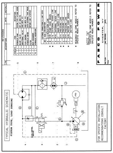
9 FIXED DISPLACEMENT TYPE GEAR PUMP TYPICAL HYDRAULIC SCHEMATIC 8 1. HYDRAULIC PUMP 2. PRESSURE RELIEF VALVE 3. CONTROL VALVE 4. PRIORITY FLOW CONTROL* 5. GENERATOR HYRAULIC MOTOR 6. CASE DRAIN LINE** 9 7. RETURN LINE FILTER 8. OIL COOLER 9. HYDRAULIC FLUID RESERVOIR * Some units may be equipped with integral priority flow control, refer to specific model number. ** External case drain line may be required on some units refer to specific model number. When external case drain is required it should be unobstructed direct return to reservoir with a minimum I.D. no less than that of case drain port on generator motor. FOR SPECIFIC INSTALLATION RECOMMENDATIONS CONSULT FACTORY Page 9
10 BRUSHLESS GENERATOR WIRING Page 10
11 FABCO BY-PASS FLOW CONTROL FABCO PN NOTE: THIS ASSEMBLY ONLY NEEDED WITH FIXED DISPLACEMENT TYPE GEAR PUMP. Page 11
12 Page 12
13 Page 13
HYDRO 600E 10cc. Hydraulic Generator INSTRUCTION MANUAL FOR MODEL. Setting the Standard in Mobile Power
 Setting the Standard in Mobile Power INSTRUCTION MANUAL FOR MODEL HYDRO 600E 10cc Hydraulic Generator Manufacturing of: Vehicle Mounted Generators Hydraulic Generators P.O. Box 582 Chester, NY 10918 845-469-9151
Manufacturing of: Vehicle Mounted Generators Hydraulic Generators
 Setting the Standard in Mobile Power for Model HYDRO 14KEP-11 Hydraulic Generator Manufacturing of: Vehicle Mounted Generators Hydraulic Generators P.O. Box 582 Chester, NY 10918 845-469-9151 Fax: 845-469-7871
HYDRO Instruction Manual for Model. Hydraulic Generator. Setting the Standard in Mobile Power
 Setting the Standard in Mobile Power for Model HYDRO 400-6 Hydraulic Generator Manufacturing of: Vehicle Mounted Generators Hydraulic Generators P.O. Box 582 Chester, NY 10918 845-469-9151 Fax: 845-469-7871
Manufacturing of: Vehicle Mounted Generators Hydraulic Generators
 Setting the Standard in Mobile Power for Model HYDRO 350 SJ Hydraulic Generator Manufacturing of: Vehicle Mounted Generators Hydraulic Generators P.O. Box 582 Chester, NY 10918 845-469-9151 Fax: 845-469-7871
HYDRO 300C-6 Hydraulic Generator
 Setting the Standard in Mobile Power for Model HYDRO 300C-6 Hydraulic Generator Manufacturing of: Vehicle Mounted Generators Hydraulic Generators P.O. Box 582 Chester, NY 10918 845-469-9151 Fax: 845-469-7871
HYDRO - 200CX HZ
 Setting the Standard in Mobile Power for Model HYDRO - 200CX - 4.8 50HZ HYDRAULIC GENERATOR Manufacturing of: Vehicle Mounted Generators Hydraulic Generators P.O. Box 582 Chester, NY 10918 845-469-9151
HYDRO 12KCD 16-3 Hydraulic Generator
 Setting the Standard in Mobile Power for Model HYDRO 12KCD 16-3 Hydraulic Generator Manufacturing of: Vehicle Mounted Generators Hydraulic Generators P.O. Box 582 Chester, NY 10918 845-469-9151 Fax: 845-469-7871
HYDRO 800KEP 11-3 Hydraulic Generator
 Setting the Standard in Mobile Power for Model HYDRO 800KEP 11-3 Hydraulic Generator Manufacturing of: Vehicle Mounted Generators Hydraulic Generators P.O. Box 582 Chester, NY 10918 845-469-9151 Fax: 845-469-7871
Instruction Manual for Model HYDRO 12-KP 11-3 PHASE GENERATOR. Hydraulic Generator. Manufacturing of: Vehicle Mounted Generators Hydraulic Generators
 Setting the Standard in Mobile Power Instruction Manual for Model HYDRO 12-KP 11-3 PHASE GENERATOR Hydraulic Generator Manufacturing of: Vehicle Mounted Generators Hydraulic Generators P.O. Box 582 Chester,
SGB12000HX PORTABLE GENERATOR
 12KWG022004KOD PRINTED IN CANADA SGB12000HX PORTABLE GENERATOR OPERATING INSTRUCTIONS AND PARTS MANUAL John Brooks Company Limited Mississauga, Ontario L5N 7K5 12 1 Troubleshooting The majority of problems
Manufacturing of: Vehicle Mounted Generators Hydraulic Generators
 Setting the Standard in Mobile Power Instruction Manual for Model HYDRO ARC-S-6500 JSBC Hydraulic Generator Welder Manufacturing of: Vehicle Mounted Generators Hydraulic Generators P.O. Box 582 Chester,
PANCAKE CAPACITOR GENERATOR Installation, Operation and Maintenance Manual
 PANCAKE CAPACITOR GENERATOR Installation, Operation and Maintenance Manual A Regal Brand TABLE OF CONTENTS INTRODUCTION 2 General Data 2 Initial Inspection 2 SAFETY 2 INSTALLATION 3 Location / Environment
Principals of Operation... 1 Rotary Vane Priming Pump VPE and VPES... 2 Rotary Vane Priming Pump VPO and VPOS Priming Valve...
 Priming Systems Installation Priming Systems Operation & Maintenance Form No. F 1031 Section 2312 Issue Date 10/07/94 Rev. Date 02/27/06 Table of Contents Illustrations Principals of Operation...........................
 Motor Trouble-Shooting Chart Caution:. Disconnect power to the motor before performing service or maintenance.. Discharge all capacitors before servicing motor.. Always keep hands and clothing away from
ALTERNATOR - CHRYSLER 40/90-AMP & 50/120 AMP
 ALTERNATOR - CHRYSLER 40/90-AMP & 50/120 AMP 1988 Chrysler LeBaron Convert/Coupe 1988 ELECTRICAL Chrysler Motors 40/90 & 50/120 Amp Alternators FWD Models DESCRIPTION The charging system consists of an
Commercial generator set Hydraulic Series HG 25000
 Commercial generator set Hydraulic Series HG 25000 Features and benefits Can start and run generator set anytime the vehicle engine is operating Cummins Onan custom engineered hydraulic generator set system
2015 EDITION SUBMERSIBLE MOTORS AIM MANUAL. APPLICATION INSTALLATION MAINTENANCE 60 Hz, Single-Phase and Three-Phase Motors. franklinwater.
 0 EDITION AIM MANUAL SUBMERSIBLE MORS APPLICATION INSTALLATION 60 Hz, Single-Phase and Three-Phase Motors franklinwater.com All Motors System Troubleshooting Motor Does Not Start A. No power or incorrect
Starting up hydraulic systems
 General / Installation A hydraulic system that operates economically, safely, and trouble-free requires careful planning, as well as proper installation and start-up. Conscientious maintenance has a considerable
PM300E Voltage Regulator Instruction Manual
 PM300E Voltage Regulator Instruction Manual A Regal Brand 1. INTRODUCTION The PM300E voltage regulator is an encapsulated electronic voltage regulator which controls the output of a brushless AC generator
CHARGING SYSTEM 8C - 1 CHARGING SYSTEM CONTENTS
 ZG CHARGING SYSTEM 8C - 1 CHARGING SYSTEM CONTENTS page GENERAL INFORMATION OVERVIEW... 1 DESCRIPTION AND OPERATION BATTERY TEMPERATURE SENSOR... 2 CHARGING SYSTEM OPERATION... 1 ELECTRONIC VOLTAGE REGULATOR...
Track Drive Circuit - General System. Simplified Travel Circuit Diagrams: Neutral Controls Forward Travel Reverse Travel
 Section 7.1 Track Drive Circuit - General System Simplified Travel Circuit Diagrams: Neutral Controls... 7.1.2 Forward Travel... 7.1.4 Reverse Travel... 7.1.5 General... 7.1.3 Track Drive Circuit: General...
Model 5-025, 5-050, &
 Model 5-025, 5-050, 5-075 & 5-150 7 Model 5-025, 5-050, 5-075 & 5-150 8 Eductor Block Exploded View Model 5-025, 5-050, 5-075 & 5-150 9 Figure 1 Item Part Name Model Model Model Model 5-025 5-050 5-075
Machine Component Identification Items: , ,
 Machine Component Identification Items:, 165603, 165604 Ref. Description Ref. Description 1 Recoil 9 Generator Head 2 Fuel Valve Lever 10 6.5 Gallon Gas Tank 3 Engine Key Switch (165604 only) 11 Muffler
WOB-L. PISTON Pumps and Compressors. 607/668/669/688/689 Series MODELS:
 WOB-L PISTON Pumps and Compressors 607/668/669/688/689 Series MODELS: Standard models available. 607CA22, 607CA32, 607CD22, 607CD32 668CE44, 668CGHI44 688CE44, 688CGHI44 669CE44, 669CHGI44 689CE44, 689CGHI44
ALTERNATOR - BOSCH 35/75-AMP & 40/90-AMP
 ALTERNATOR - BOSCH 35/75-AMP & 40/90-AMP 1988 Chrysler LeBaron Convert/Coupe 1988 ALTERNATORS & REGULATORS Chrysler Motors - Bosch 35/75 & 40/90 Amp Alternator All Models DESCRIPTION The charging system
CHARGING SYSTEM 8C - 1 CHARGING SYSTEM CONTENTS
 TJ CHARGING SYSTEM 8C - 1 CHARGING SYSTEM CONTENTS page DESCRIPTION AND OPERATION BATTERY TEMPERATURE SENSOR... 2 CHARGING SYSTEM OPERATION... 1 ELECTRONIC VOLTAGE REGULATOR... 2 GENERATOR... 1 DIAGNOSIS
Unit 32 Three-Phase Alternators
 Unit 32 Three-Phase Alternators Objectives: Discuss the operation of a three-phase alternator. Explain the effect of rotation speed on frequency. Explain the effect of field excitation on output voltage.
Operation & Service Manual
 Operation & Service Manual Model: 5B20 Hydraulic Power Unit 07/2011 - Rev. 06 Includes Illustrated Parts Lists 1740 Eber Rd Tronair, Inc. Phone: (419) 866-6301 Holland, OH 43528-9794 www.tronair.com 800-426-6301
CONTENTS. Product Features and Specifications...1. Installation Requirement...3. Steps of Installation...4. Exploded View Test Run...
 TP10AS 2-POST LIFT CONTENTS Product Features and Specifications...1 Installation Requirement...3 Steps of Installation...4 Exploded View...24 Test Run....28 Operation Instruction...29 Maintenance...30
AHFP-im-issue INSTRUCTION MANUAL HIGH FLOW DIESEL PUMP AHFP70LPM (70LPM) AHFP100LPM (100LPM) AHFP150LPM (150LPM) AHFP70LPM AHFP100LPM AHFP150LPM
 AHFP100LPM (100LPM) AHFP150LPM (150LPM) AHFP70LPM AHFP100LPM AHFP150LPM") AHFP-im-issue2-2017 INSTRUCTION MANUAL AHFP70LPM AHFP100LPM AHFP150LPM INTRODUCTION Thank you for purchasing a Macnaught 240 volt electric diesel fuel pump The Macnaught range of 240 volt electric diesel
AHFP-im-issue2-2017 INSTRUCTION MANUAL AHFP70LPM AHFP100LPM AHFP150LPM INTRODUCTION Thank you for purchasing a Macnaught 240 volt electric diesel fuel pump The Macnaught range of 240 volt electric diesel
D-Series Blowers and Exhausters
 Operation and Maintenance Manual D-Series MONOXIVENT - SOURCE CAPTURE SYSTEMS - info@ Oct. - 2015 MONOXVENT BLOWERS AND EXHAUSTERS D05-1 D05-3 D10-1 D10-3 D15-1 D15-3 D20-1 D20-3 D30-1 D30-3 ½ HP TEFC
WELDING FUME EXHAUSTERS & ARMS
 WELDING FUME EXHAUSTERS & ARMS The Ace 75 Series is our flexible and effective line of welding fume exhausters and extraction arms for shops that elect to exhaust their weld fumes outdoors instead of through
Installation & Operating Manual
 Installation & Operating Manual 6 WS Series Submersible Turbine Pumps Congratulations On Your Choice In Purchasing This Webtrol Pump 6/11 Edition Its Quality is unsurpassed in material and workmanship
User s Manual D-Series Blowers and Exhausters
 User s Manual D-Series Blowers and Exhausters D05-1 ½ HP TEFC 115/230 VOLTS, 1 PH D05-3 ½ HP TEFC 208/230/460 VOLTS, 3 PH D10-1 1 HP TEFC 115/230 VOLTS, 1 PH D10-3 1 HP TEFC 208/230/460 VOLTS, 3 PH D15-1
Hydrostatic Drive. 1. Main Pump. Hydrostatic Drive
 Hydrostatic Drive The Hydrostatic drive is used to drive a hydraulic motor at variable speed. A bi-directional, variable displacement pump controls the direction and speed of the hydraulic motor. This
This chapter contains information on DC Generation, External Power, and Electrical Load Distribution.
 CIRRUS AIRPLANE MAINTENANCE MANUAL Electrical Power CHAPTER 24-00: ELECTRICAL POWER GENERAL 24-00: ELECTRICAL POWER 1. General This chapter contains information on DC Generation, External Power, and Electrical
CONTENTS. Product Features and Specifications Installation Requirement Steps of Installation 4. Exploded View Test Run...
 CONTENTS Product Features and Specifications... 1 Installation Requirement... 3 Steps of Installation 4 Exploded View... 14 Test Run... 16 Operation Instruction... 19 Maintenance... 20 Trouble Shooting...
Portable Oil Free Silent Series Compressor Operating Instructions
 Portable Oil Free Silent Series Compressor Operating Instructions NOTICE Carefully read this instruction manual before attempting to operate this compressor. MODEL # SERIAL # 1-800-551-2406 www.eaglecompressor.com
CONTENTS. Product Features and Specifications Installation Requirement Installation Exploded View Operation Instruction...
 1 CONTENTS Product Features and Specifications... 3 Installation Requirement... 5 Installation... 6 Exploded View... 20 Test... 22 Operation Instruction... 25 Maintenance... 26 Trouble Shooting... 27 Parts
3000W POWER INVERTER. User Manual
 3000W POWER INVERTER User Manual Posts AC outlets Digital display ON/OFF button Remote control connection port (remote control switch is not included) USB port Two set of heavy duty input cable P a g e
Power Steering Units - Eaton / Char-Lynn
 A fully fluid linked steering control unit consisting of a manually operated directional control servo valve and with a feedback meter element in a single body. It is used principally for fluid linked
Section 7.1. Wheel Drive Circuit - General System
 Section 7.1 Wheel Drive Circuit - General System Simplified Travel Circuit Diagrams: Neutral Controls... 7.1.2 Forward Travel... 7.1.4 Reverse Travel... 7.1.5 General... 7.1.3 Wheel Drive Circuit: General...
FAULT FINDING MANUAL. For Stamford AC Generators
 FAULT FINDING MANUAL For Stamford AC Generators 1 SAFETY PRECAUTIONS Test procedures recommended in this manual assume that the reader is fully conversant with electrical safety principles, and is familiar
FIRE-POWER 12 & 14 KW SELF-CONTAINED HYDRAULICALLY DRIVEN ELECTRIC POWER GENERATOR SYSTEM
 FIRE-POWER 12 & 14 KW SELF-CONTAINED HYDRAULICALLY DRIVEN ELECTRIC POWER GENERATOR SYSTEM INSTRUCTION MANUAL ANOTHER FINE PRODUCT BY FABCO GENERATORS INC. CHESTER, NY 10918 VOICE (845)-469-9151 FAX (845)-469-7871
6L Oil-less Air Compressor 53103
 6L Oil-less Air Compressor 53103 Operating Instructions Please read and save these instructions before attempting to assemble, install, operate or maintain the product. Protect yourself and others by observing
WORKSHOP MANUAL. 63,4 cm³ chainsaws
 WORKSHOP MANUAL General failures analysis Suggested tools I. Emak tool kit II. Compression tester: to check thermal group III. Electronic tachometer: for 2 and 4 stroke engines, measurement range from
AG. 225 AGRICULTURAL SYSTEMS/ELECTRICITY AND HYDRAULICS
 AG. 225 AGRICULTURAL SYSTEMS/ELECTRICITY AND HYDRAULICS COURSE DESCRIPTION: A course designed to develop skills in operation of tools and equipment, wiring, controls, electric motors, and hydraulics. UNITS
Section 6.1. Implement Circuit - General System. General: Implement Control Valve: Implement Circuit
 Section 6.1 Implement Circuit - General System General: Implement Circuit... 6.1.3 Implement Pump Breakdown... 6.1.4 Operational Description: General... 6.1.5 Compensator Control... 6.1.6 Standby Condition...
Section 6.1. Implement Circuit - General System. General: TF Configuration TB Configurations Implement Control Valve:
 Section 6.1 Implement Circuit - General System General: TF Configuration... 6.1.3 TB Configurations... 6.1.5 Implement Pump Breakdown... 6.1.6 Operational Description: General... 6.1.7 Compensator Control...
DC disconnect. #4 AWG Negative wire
 90 ASSEMBLING A SOLAR GENERATOR Figure 11-3: Inverter Input Circuit DC disconnect #4 AWG Positive wire 75 amp fuse 12-volt deep cycle battery, 120 Ah 400 watt Inverter #4 AWG Negative wire So we should
9/3/2008. Item No. Qty. MSRP Dealer Cost. Part No. UPC Number Description Baja Description
 HG6000 Toll Free: 888-863-2252 (BAJA) PARTS AND PRICES ARE SUBJECT TO CHANGE 1 of 34 CRANKCASE ASSY 9 H60-108 883099072581 IGNITION COIL 1 1 10 H60-109 883099072598 M6 x 25 bolt 2 2 12 H60-111 883099072604
PANCAKE AND HOT DOG AIR COMPRESSORS PARTS LIST
 PANCAKE AND HOT DOG AIR COMPRESSORS MODEL H330/H331 PARTS LIST COPYRIGHT APRIL, 2003 BY GRIZZLY INDUSTRIAL, INC. WARNING: NO PORTION OF THIS MANUAL MAY BE REPRODUCED IN ANY SHAPE OR FORM WITHOUT THE WRITTEN
Battery Powered Hydraulic Pump; Kit PN [ ]
![Battery Powered Hydraulic Pump; Kit PN [ ]](/thumbs/73/68120284.jpg "Battery Powered Hydraulic Pump; Kit PN [ ]") ORIGINAL INSTRUCTIONS Battery Powered Hydraulic Pump; Kit PN 1804111-[ ] Customer Manual 409-10060 16 NOV 16 Rev D SAFETY PRES IMPORTANT SAFETY INFO READ THIS FIRST!... 2 SAFETY PRES AVOID INJURY READ
ORIGINAL INSTRUCTIONS Battery Powered Hydraulic Pump; Kit PN 1804111-[ ] Customer Manual 409-10060 16 NOV 16 Rev D SAFETY PRES IMPORTANT SAFETY INFO READ THIS FIRST!... 2 SAFETY PRES AVOID INJURY READ
Tests & Adjustments - General Machine. General Safety Hydraulic Tank Turbo Boost Regulator
 Section 8.1 Tests & Adjustments - General Machine General Safety......................................... 8.1.2 Hydraulic Tank Turbo Boost Regulator........................ 8.1.2 Hydraulic Tank Safety
Designed for Light to Medium Industrial Repair
 ALL-IN-ONE POWER SYSTEM welder generator air compressor optional battery booster Designed for Light to Medium Industrial Repair The Air N Arc 150 is the system to choose when weight is the issue. The three
WARNING This manual should only be used by a qualified Service Technician. FinishPro 390/395 Airless/Air-Assisted Sprayer Repair Electrical Manual
 FinishPro 390/395 Airless/AirAssisted Sprayer Repair Electrical Manual First choice when quality counts. Rev. B 10/11 /07 FinishPro 395 3.00 ti9026a Red Yel Yel Air Hose Connection FinishPro 390 Exhaust
DIAGNOSIS AND TESTING
 414-00-1 Charging System General Information 414-00-1 DIAGNOSIS AND TESTING Charging System The charging system voltage is controlled by the PCM. The generator charges the battery, and at the Special Tool(s)
3 Phase Smart Controller
 3 Phase Smart Controller Installation and Owner s Manual STP-SCIII 208-230 VAC, 60Hz, 120 Volt Coil Franklin Fueling 3760 Marsh Rd. Madison WI 53718 USA Tel: +1 608 838 8786 800 225 9787 Fax: +1 608 838
PRO6.4, PRO6.4E, PRO9.0, PRO9.0E Generator Service Manual
 PRO6.4, PRO6.4E, PRO9.0, PRO9.0E Generator Service Manual IMPORTANT: Read all safety precautions and instructions carefully before operating equipment. Ensure equipment is stopped and level before performing
XCITE Owner s Manual. Reso-not TM Damping System XCITE 1502C HYDRAULIC POWER SUPPLY
 Reso-not TM Damping System XCITE Owner s Manual 1502C HYDRAULIC POWER SUPPLY Xcite Systems Corporation 675 Cincinnati RDS Batavia - 1 Pike Cincinnati, Ohio 45245 Tel: (239) 980-9093 Fax: (239) 985-0074
Section 6.1. Implement Circuit - General System. General: TF Configuration TB Configurations Implement Control Valve:
 Section 6.1 Implement Circuit - General System General: TF Configuration... 6.1.3 TB Configurations... 6.1.5 Implement Pump Breakdown... 6.1.6 Operational Description: General... 6.1.7 Compensator Control...
ALTERNATOR REQUESTED INFORMATION. Vehicles With Dual Generator [ Engine Mount - LH ] 2007 Ford Pickup 6.0L Eng F350 Super Duty
![ALTERNATOR REQUESTED INFORMATION. Vehicles With Dual Generator [ Engine Mount - LH ] 2007 Ford Pickup 6.0L Eng F350 Super Duty](/thumbs/72/66590437.jpg "ALTERNATOR REQUESTED INFORMATION. Vehicles With Dual Generator [ Engine Mount - LH ] 2007 Ford Pickup 6.0L Eng F350 Super Duty") ALTERNATOR 2007 Ford Pickup 6.0L Eng F350 Super Duty REQUESTED INFORMATION Vehicles With Dual Generator [ Engine Mount - LH ] Fig 1: Rotating Drive Belt Tensioner Clockwise 1. Remove the accessory drive
ALTERNATOR 2007 Ford Pickup 6.0L Eng F350 Super Duty REQUESTED INFORMATION Vehicles With Dual Generator [ Engine Mount - LH ] Fig 1: Rotating Drive Belt Tensioner Clockwise 1. Remove the accessory drive
NIGHT-LITE PRO II. Electrical System Troubleshooting Guide and Procedures
 NIGHT-LITE PRO II Electrical System Troubleshooting Guide and Procedures Allmand Bros. Inc. PO Box 888 1502 W. 4 th Ave. Holdrege NE 68949 USA 308-995-4495 Phone 800-562-1373 Toll-Free www.allmand.com
ATD-5925 RECHARGEABLE 12 VOLT 18 AMP/HOUR JUMP START WITH BUILT-IN 260 PSI AIR COMPRESSOR OWNERS MANUAL
 ATD-5925 RECHARGEABLE 12 VOLT 18 AMP/HOUR JUMP START WITH BUILT-IN 260 PSI AIR COMPRESSOR OWNERS MANUAL 1000 PEAK AMPS/400 CRANKING AMPS OF STARTING POWER. STARTS CARS, TRUCKS, RV s AND BOATS WITHOUT THE
Spare Parts List. EW-3500-C and D EW-4200-C and D Marine Diesel Generators
 ENTEC WEST, INC. Spare Parts List EW-3500-C and D EW-4200-C and D Marine Diesel Generators Every generator produced by Entec West, Inc. has been recorded in a master computer file by serial number. This
Pretest Module 21 Units 1-3 AC Generators & Three-Phase Motors
 Pretest Module 21 Units 1-3 AC Generators & Three-Phase Motors 1. What are the two main parts of a three-phase 2. Which part of a three-phase squirrel-cage induction motor is a hollow core? 3. What are
OWNER S MANUAL. Please read installation and operation instruction before using this Power inverter.
 OWNER S MANUAL DP AUDIO Model No. DN350 12 Volt DC to 115 Volt AC 150 WATT 300WATT HIGH SURGE POWER INVERTER Please read installation and operation instruction before using this Power inverter. Contents
POWER MODULE MTU 16V4000 DS2560
 POWER MODULE MTU 16V4000 DS2560 50 Hz: 1,912-2,560 kva/400v 60 Hz: 1,807-2,321 kwe/480v Optional equipment shown. Standard equipment may vary. Certifications and Standards // Emissions - Fuel optimized
VAC Electrical Requirements. VDC Electrical Requirements
 Item VAC Electrical Requirements VDC Electrical Requirements Voltmeter Equipped Display Lights Gasoline Engine Fuel Tank Capacity Estimated Run Time Approx. Weight Generator Type Description 120 Volts
4.0L CEC SYSTEM Jeep Cherokee DESCRIPTION OPERATION FUEL CONTROL DATA SENSORS & SWITCHES
 4.0L CEC SYSTEM 1988 Jeep Cherokee 1988 COMPUTERIZED ENGINE Controls ENGINE CONTROL SYSTEM JEEP 4.0L MPFI 6-CYLINDER Cherokee, Comanche & Wagoneer DESCRIPTION The 4.0L engine control system controls engine
INDEX Section Page Number Remarks
 INDEX Section Page Number Remarks Synchronous Alternators 2 4 General Fault Finding Capacitors 5 6 Fault Finding & Testing Diodes,Varistors, EMC capacitors & Recifiers 7 10 Fault Finding & Testing Rotors
Model No. 668D3. COFFEPUMP Part No Product Code: O/C GJAN21.DB6B-DC310B
 Model No. 668D3 COFFEPUMP Part No. 9168 Product Code: O/C GJAN21.DB6B-DC310B OVERHAUL MANUAL with ILLUSTRATED PARTS LIST Page 1 of 15 P/N 5914 Rev D 01/17/05 1.0 Introduction 1.1 Description 1.1.1 The
RENTAL DIESEL GENERATOR SET
 RENTAL DIESEL GENERATOR SET MODEL HRIW-45 T4F 60Hz RENTAL/PRIME/STANDBY POWER EPA 36kW/60Hz/Rental/1800RPM VOLTAGE VAC 120/240V 120/208V 139/240V 277/480V 347/600V** RATING Prime Standby Prime Standby
OWNER S MANUAL POWER INVERTER
 OWNER S MANUAL POWER INVERTER PINV4 PINV5 PINV6 PINV4 600WATT PINV5 800WATT PINV6 1000WATT www.pyleaudio.com INTRODUCTION Thank you for purchasing the PYLE View DC to AC Power Inverter. The PINV4/PINV5/PINV6
ADVANCED PID TROUBLESHOOTING
 ADVANCED PID TROUBLESHOOTING August 29, 2016 A KEY POINT If the drive is telling you something via a Fault, then the problem is probably not the drive. The drive is recognizing a fault and telling you
PT, PTS & PTP Series Pump/Reservoirs
 PT, PTS & PTP Series Pump/Reservoirs Installation, Operation and Maintenance Manual Table of Contents FOREWORD... 1 INSTALLATION... 1 RECEIVING INSPECTION... 1 RIGGING, HANDLING, AND LOCATING EQUIPMENT...
INDUSTRIAL GENERATOR SERVICE
 INDUSTRIAL GENERATOR SERVICE PREVENTATIVE MAINTENANCE PROGRAM Customer: Date: Contact Person: Work Order #: Contact Number: ( ) Technician: INSPECTION COMPONENTS 1. GENERAL Check fuel tank level. Check
AUTO CHARGE D2 MODEL #: AUTOMATIC TRIPLE OUTPUT BATTERY CHARGER INSTRUCTION MANUAL
 INSTRUCTION MANUAL AUTO CHARGE D2 AUTOMATIC TRIPLE OUTPUT BATTERY CHARGER Designed Specifically for Vehicles with DDEC ENGINES MODEL #: 091-74-12 INPUT: 120 Volt, 60 Hz, 8 Amps OUTPUT VEHICLE BATTERY 1
Spreader Valves SPR-2FFL12, SPR-2FFLC12 & SPR-2FFLW86
 Spreader Valves, & SCHEMATIC MODEL PRESSURE FLOW* WEIGHT Quick Reference Page 3 Spreader Valve, Dual Flow Regulation, Compensated, Manual Dump, Gear Pump Circuit 138 bar [2000 psi] [30 US g/m] 2.62 kg
SERVICE MANUAL DGK25E DGK25EU
 SERVICE MANUAL DGK25E DGK25EU WARNING Read this manual and familiarize yourself with its contents. This equipment is designed for generating power source of electric tools, home appliances and lights.
Multiquip Submersible Pump Model ST-3050D
 OPERATION AND PARTS MANUAL Multiquip Submersible Pump Model ST-3050D COPYRIGHT 2002, MULTIQUIP INC. Revision #1 (11/18/02) MULTIQUIP INC. 18910 WILMINGTON AVENUE CARSON, CALIFORNIA 90746 310-537-3700 800/421-1244
Section 6.1. Implement Circuit - General System. General: Implement Control Valve:
 Section 6.1 Implement Circuit - General System General: Implement Circuit... 6.1.3 Implement Pump Breakdown... 6.1.4 Operational Description: General... 6.1.5 Compensator Control... 6.1.6 Standby Condition...
Section 6.1. Implement Circuit - General System. General: TF Configuration TB Configurations Implement Control Valve:
 Section 6.1 Implement Circuit - General System General: TF Configuration... 6.1.3 TB Configurations... 6.1.5 Implement Pump Breakdown... 6.1.6 Operational Description: General... 6.1.7 Compensator Control...
WALKIE HIGH LIFT HYDRAULIC SYSTEM
 WALKIE HIGH LIFT HYDRAULIC SYSTEM W30-40ZA [B453]; W20-30ZR [B455]; W25-30-40ZC [B454] PART NO. 1524251 2000 SRM 1025 SAFETY PRECAUTIONS MAINTENANCE AND REPAIR When lifting parts or assemblies, make sure
Pyrolance, LLC SPECIFICATIONS FOR DIESEL ENGINE DRIVEN ULTRA HIGH PRESSURE FIRE FIGHTING SYSTEM B2000 M-D
 SPECIFICATIONS FOR DIESEL ENGINE DRIVEN ULTRA HIGH PRESSURE FIRE FIGHTING SYSTEM B2000 M-D 1 HIGH PRESSURE FIRE FIGHTING SPECIFICATIONS Scope and General Design Requirements A fire fighting system shall
Charging Systems. ATASA 5 th. ATASA 5 TH Study Guide Chapter 19 Pages Charging Systems 42 Points. Please Read The Summary
 ATASA 5 TH Study Guide Chapter 19 Pages 571 595 42 Points Please Read The Summary 1. The primary purpose of the charging system is to the battery with a constant and relatively low charge after it has
LINEAR ACTUATOR MODULE Page 5-1. Table Of Contents
 LINEAR ACTUATOR MODULE Page 5-1 Table Of Contents Section Description Page # 5. Linear Actuator Module... 5-2 5.1 Description... 5-2 5.2 Operation... 5-2 5.2.1 Sensors... 5-3 5.2.1.1 Linear Sensor... 5-3
Item No. Specifications Selection Performance Pump Sectional View Chart Curve Dimensions
 Model CDU, Contents CDU, Item No. Specifications Selection Performance Pump Sectional View Chart Curve Dimensions CDU70/1-3/4HP CDU70/3-1 1 /2HP CDU70/5-2HP CDU120/1-1HP CDU120/3-1 1 /2HP 3 5, 311 6 311
Intake Air Temperature 2 (IAT2 ) Sensor
 Sensor") Page 1 of 6 Year = 2011 Model = Mustang Engine = 5.0L VIN = IDS Version = t Available Intake Air Temperature 2 ( ) Sensor This pinpoint test is intended to diagnose the following: sensor (12A697) harness
Page 1 of 6 Year = 2011 Model = Mustang Engine = 5.0L VIN = IDS Version = t Available Intake Air Temperature 2 ( ) Sensor This pinpoint test is intended to diagnose the following: sensor (12A697) harness
1/12, 1/6, 1/4, 1/3, 1/2, 3/4 & 1.0 HP
 Articulating Piston TAskair (TA) Series /, /6, /4, /3, /, 3/4 &.0 HP MODELS TA-0-DC (70046) TA-30-DC (7004) TA-40-DC (7005) TA-40-DC (70047) TA-50-DC (70058) TA-50E (70063) TA-50E (70064) TA-60E (70066)
USER S MANUAL FOR F & Q. Submersible Sewage Pumps
 USER S MANUAL FOR F & Q Submersible Sewage Pumps 50WQ Series The F&Q pumps are carefully inspected and tested to ensure operating performance and safety. However, failure to follow the instructions and
REPAIR MANUAL AFX8010
 REPAIR MANUAL AFX 1 27/05/2004 Contents INTRODUCTION DISTRIBUTION SYSTEMS POWER PRODUCTION POWER TRAIN TRAVELLING BODY AND STRUCTURE TOOL POSITIONING CROP PROCESSING A B C D E G K AFX 1 27/05/2004 INTRODUCTION
ALTERNATOR PRECAUTIONS. Some precautions should be taken when working on this, or any other, AC charging system.
 The alternator charging system is a negative (-) ground system which consists of an alternator, a regulator, a charge indicator, a storage battery and wiring connecting the components, and fuse link wire.
ELECTRICAL SYSTEM RP-7
 ELECTRICAL SYSTEM RP-7 This section of the manual does not include integral electrical components of the engine. Refer to section Engine RP-1 for details. This section of the manual is divided into three
CONTENTS. Product Features and Specifications...1. Installation Requirement Steps of Installation.. 5. Exploded View Test Run...
 CONTENTS Product Features and Specifications...1 Installation Requirement... 3 Steps of Installation.. 5 Exploded View...18 Test Run...21 Operation Instruction...22 Maintenance... 23 Trouble Shooting...
PM300 VOLTAGE REGULATOR INSTRUCTION MANUAL
 PM300 VOLTAGE REGULATOR INSTRUCTION MANUAL INTRODUCTION The PM300 voltage regulator is an encapsulated electronic voltage regulator that controls the output of a brushless AC generator by regulating the
PRECISION UK Ltd DUPLEX AGSS PLANT
 DUPLEX AGSS PLANT Contents Page Section Page Product Description General 3 AGSS Plant 3 AGSS Remote Switch 3 Operation General 4 Safety General 5 Installation General 5 Mechanical 5 Electrical 7 Wiring
Pretest Module 21 Units 1-4 AC Generators & Three-Phase Motors
 Pretest Module 21 Units 1-4 AC Generators & Three-Phase Motors 1. What are the two main parts of a three-phase motor? Stator and Rotor 2. Which part of a three-phase squirrel-cage induction motor is a
SPECIFICATIONS FOR DIESEL DRIVEN ENGINE ULTRA HIGH PRESSURE FIRE FIGHTING SYSTEM B2000 M-D
 SPECIFICATIONS FOR DIESEL DRIVEN ENGINE ULTRA HIGH PRESSURE FIRE FIGHTING SYSTEM B2000 M-D HIGH PRESSURE FIRE FIGHTING SPECIFICATIONS Scope and General Design Requirements A firefighting system shall be
INSTALLATION INSTRUCTIONS
 www.burcam.com 2190 Dagenais Blvd.West TEL: 514.337.4415 LAVAL (QUEBEC) FAX: 514.337.4029 CANADA H7L 5X9 info@burcam.com Your pump has been carefully packaged at the factory to prevent damage during shipping.