CONTENTS. Product Features and Specifications Installation Requirement Steps of Installation 4. Exploded View Test Run...
|
|
|
- Cameron Fletcher
- 6 years ago
- Views:
Transcription
1 CONTENTS Product Features and Specifications... 1 Installation Requirement... 3 Steps of Installation 4 Exploded View Test Run Operation Instruction Maintenance Trouble Shooting Parts List... 22

2 I. PRODUCT FEATURES AND SPECIFICATIONS CLEARFLOOR CHAIN-DRIVE MODEL FEATURES Model 9OHSC (See Fig. 1) Dual hydraulic cylinders designed and made on ANSI standard, utilizing NOK oil seal for cylinder. Self-lubricating UHMW Polyethylene sliders and bronze bush. Single-point safety release and dual safety lock design. Clear floor design, provide unobstructed floor space. Overhead safety shutoff device. MODEL 9OHSC SPECIFICATIONS Fig. 1 Model Style Lifting Capacity Lifting Time Lifting Height Lifting Height w/ Truck Adapters Overall Height Overall Width Width Between Posts Minimum Pad Height for stackable adapters Motor 9OHSC Clear-floor Chain-assist cylinders 9,000 lbs 45 S 70 7/8 81 3/ /2 3 1/2 3.0 HP 1

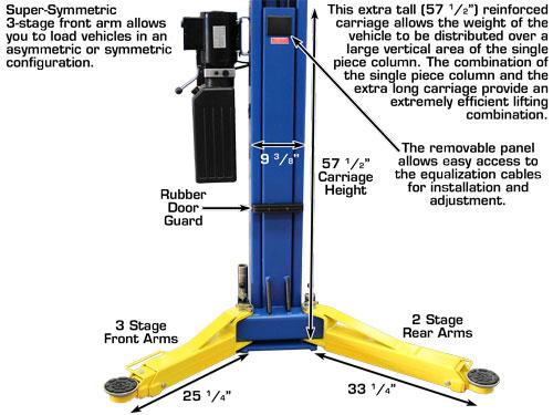
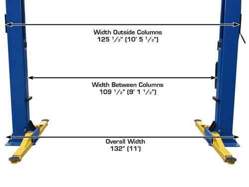
3 Arm Swing View Column Dimensions 2

")

")


4 II. INSTALLATION REQUIREMENT A. TOOLS REQUIRED Rotary Hammer Drill (3/4 ) Carpenter s Chalk Hammer Screw Driver Set 4ft Level Tape Measure (25ft) Crescent Wrench (12") Pliers Ratchet Spanner With Socket (30mm) Socket Head Wrench (6 # ) Wrench set (10 #, 13 #, 14 #, 15 #, 17 #, 19 #, 24 #, 27 # ) Vise Grips Fig. 3 3
5 B. CONCRETE SPECIFICATIONS (See Fig. 4) Specifications of concrete must be adhered to the specification as following. Failure to do so may result in lift and or vehicle falling. 1. Concrete must have 4 inches minimum and must be totally cured before lift installation. 2. Concrete must be in good condition and must have a test strength 3,000psi minimum. 3. Floors must be level with no cracks or holes. Concrete intensity must be 3000 psi minimum 4 Fig. 4 C. POWER SUPPLY 220 volt single phase 30 amp breaker with minimum of 10 gauge wire III. STEPS OF INSTALLATION A. Installation Location Check and insure the installation location (concrete, layout, space size etc.) is suitable for lift installation. B. Use a carpenter s chalk line to establish installation layout (See Fig. 5). 132 Fig. 5 4
 Fig.")


6 C. Check the Parts before assembly 1 Packaged lift and Hydraulic Power Unit (See Fig. 6) Fig Move the lift aside with a fork lift or hoist, and open the outer packing carefully (See Fig. 7) Shipment Part list Serial No. Top Beam Parts Box Fig Remove the parts from inside the column and remove the parts box, and check the parts according to the shipment parts list. (See Fig. 8) Fig. 8 5


 Fig. 10 6.")

7 4. Loosen the bolts on the upper package stand and remove the upper column. (See Fig. 9) Fig. 9 5 Open the box of parts and check the parts according to parts box list. (See Fig. 10) Fig Check the parts in the parts bag according to parts bag list. (See Fig.11) Fig. 11 6
. Install the overhead cross beam.")
 Use M10 x 35 Hex Bolts, Nylock Nuts & Washers to install overhead beam Rubber Door Protectors Fig. 12 Fig. 13 E. Drill and install anchor bolts 1.")
8 D. Position columns 1. Snap a chalk line so the columns will be exactly parallel from each other. 2. Position the columns upright on the installation layout. Position the offside column parallel to the power side column at the approximate overall width (132 ). Install the overhead cross beam. Do not drill holes for anchor bolts until overhead cross beam is installed (See Fig. 12) 3. Position the columns making sure the base plates align with the chalk line. Install the rubber door protectors (See Fig. 13) Use M10 x 35 Hex Bolts, Nylock Nuts & Washers to install overhead beam Rubber Door Protectors Fig. 12 Fig. 13 E. Drill and install anchor bolts 1. Position the columns so their positions are square with the chalk line. 2. Prepare the Anchor Bolts. (See Fig. 14) Fig. 14 7


 Install the safety cable from the off side safety assembly to the power side safety assembly and")
9 3. Use a hammer drill (3/4 bit), drill all the anchor holes and install the anchor bolts. Check the posts for plumb with level bar, and adjust with the horseshoe shims if the columns are not plumb. Tighten the anchor bolts between 60 and 86 foot pounds. (See Fig. 15). Drill the anchor holes to the length of the anchor bolts Fig. 15 Drilling Bolting Tighten F. Install Safety Lock Device and Safety Cable (See Fig. 16) Install the safety cable from the off side safety assembly to the power side safety assembly and through the top beam. Do not tighten the safety cable at this time View A Connecting direction of Safety Cable View B Fig. 16 8


10 G. Install Cables (See Fig. 17) Manually lift each carriage until they rest on the first set of safety locks. Fig. 17 9
 Fig.")


11 H. Oil Hose Assembly. (See Fig. 18) Fig. 18 Use Teflon tape to seal pipe threads. Do not use Teflon tape on hydraulic hose ends. 10
 Assemble Control Bar Bracket using M12 x 20 Hex Head")

 Oil Hose Loosen the screw on the Drive Rod to adjust.")

12 I. Install Control Bar (See Fig. 19) Assemble Control Bar Bracket using M12 x 20 Hex Head Screw with Nylock Nut and Washer Assemble Limit Switch next to Power Side Column Fig. 19 I. Install Limit Switch (See Fig. 20) Oil Hose Loosen the screw on the Drive Rod to adjust. Tighten the screw after adjustment Cable Fix protective rubber Ring at cable exit Adjust Drive Rod of Limit Switch Limit Switch fixed on Top Beam Fig. 20 Limit Switch connected with Cable 11

13 J. Install Hydraulic Power Unit and Oil Hose (See Fig. 21) Note: Tighten the fittings on the Hydraulic Power Unit and Oil Hoses. Install power unit using M8 x 25 Hex Head bolts, Nylock Nuts & the rubber ant-vibration washers After installing the safety locks, use M6 x 8 screws to install the safety lock covers Fig. 21 Use Teflon tape to seal pipe threads. Do not use Teflon tape on hydraulic hose ends. 12


14 K. Install Lifting Arms and Adjust the Arm Locks (See Fig. 22, 23 & 24) 1. Install the lifting arms, adjust the teeth on the arm lock assemblies so it meshes with the gear on the lifting arm, then tighten the hex bolts on the arm lock assemblies. 2. Fill the Reservoir with Hydraulic Oil. Note: In consideration of Hydraulic Power Unit s durability and keep the equipment running in peak condition, please use Hydraulic Oil AW32. Snap Ring Fig. 22 Adjust the arm lock and follow the arrow direction Fig. 23 Fig

15 Install Electrical System Connect the power source according to the data plate on the Power Unit. Remove the short Pig Tail wire connected to the AC contactor terminals. This wire was used to test the motor after production. ATLAS Single phase motor Please Note: This motor is powered by Alternating Current and the terminals on the AC contactor are not wire color specific. There are no positive or negative terminals. 1. Connect the two power supply (incoming) wires (black & white) to terminals on the AC contactor marked L2 & L3. 2. Connect the two motor wires to terminals on the AC contactor marked T2, T3. These wires are already connected from the factory. 3. Connect the short wire A2 to L3 on the AC contactor. This wire is already connected from the factory. 4. Remove the entire wire that connects from the UP button to A1 on the AC contactor. 5. Connect one of the wires (does not matter which one) on the Limit Switch to the UP button and connect the remaining Limit Switch wire to terminal A1 on the AC contactor. AC CONTACTOR 14

16 Remove this wire 15
 on")


17 Limit Switch-Connect wires to 11 & 12 (NC) on the Limit UP Button Wire Incoming Power Lines Limit Switch Wires Ground Wire Jumper Wire Motor Wires 16


18 IV. EXPLODED VIEW Fig

19 Cylinders Fig. 26 SPX Manual power unit 220V/60HZ, Single phase Fig

20 ATLAS Manual power unit 220V/60HZ, Single Phase Fig


21 Illustration of hydraulic valves for SPX & ATLAS hydraulic power unit a. SPX manual power unit, 220V/60HZ, Single phase (See Fig. 29) Capacitor Relief valve Oil return port Protective ring Auxiliary hole Release valve Check valve Auxiliary hole Oil Outlet Handle for Release valve Fig. 51 b. ATLAS manual power unit, 220V/60HZ, Single phase (See Fig. 52) Running capacitor Start capacitor Protective ring Relief valve Oil return port Oil Outlet Check valve Release valve Handle for Release valve Throttle valve Fig

 (Only for ATLAS power unit) You can adjust the lowering speed of the lift if necessary: Loosen the locking nut on the throttle valve, and")
22 V. TEST RUN 1. Adjust the Equalizing Cables Use vise grips to hold the cable fitting, use a Ratchet spanner to tighten the cable nut. Make sure the two Cables have the same tension so that two Lifting carriages synchronize while going up. Install plastic cover on the carriage. The first safety lock Carriage Rear View Fig Adjust Safety Cable Lift the carriages and lock at the same height, pull the safety cable and then release a little and tighten the cable nuts. Make sure the safety locks click at the same time. 3. Adjust the lowering speed (Adjust with a load on the lift) (Only for ATLAS power unit) You can adjust the lowering speed of the lift if necessary: Loosen the locking nut on the throttle valve, and then turn the throttle valve clockwise to decrease the lowering speed, or counterclockwise to increase the lowering speed. Do not forget to tighten the locking nut after the lower speed adjustment has been completed. Throttle Valve Fixing Nut Clockwise to decrease the down speed Counterclockwise to increase the down speed Fig
23 4. Test with load After finishing the cable adjustments, test the lift with a load. Run the lift in the low position several times. Make sure the carriages raise and lower at the same time. Make sure the safety locks release. Test run the lift to the top. If there are any issues, repeat the above adjustment(s). NOTE: If the lift bounces with a load on it; up and down, the cylinders will require bleeding. This is done by loosening the oil hose connections at the bottom of the cylinders. Fig. 32 Hydraulic System 22
24 VI.OPERATION INSTRUCTIONS 1. Keep the lift area free of clutter; 2. Position lift arms to the lowest position; 3. Open lift arms; 4. Position vehicle between columns; 5. Move arms to the vehicle s lifting points; Note: The four lift arms must make contact at the same with the vehicle s lifting points and both axles must rise off of the ground at the same time. 6. Press the UP button until the lift pads contact underside of vehicle. Check to make sure vehicle is secure; 7. Continue to raise the lift slowly to the desired working height, ensuring the balance of vehicle; 8. Push lowering handle to lower lift onto the nearest locks. The vehicle is ready to repair. Note: The lift must always be on the safety locks!!!!! To lower vehicle 1. Keep the lift area free of clutter; 2. Press the button of UP to raise the vehicle slightly, and then release the safety device, lower vehicle by pushing lowering handle. 3. Open the arms and position them to the shortest length. 4. Drive away the vehicle. 23
25 VII.MAINTENANCE SCHEDULE Monthly: 1. Re-torque the anchor bolts; 2. Check all connectors, bolts and pins to insure proper mounting; 3. Lubricate cable with lubricant; 4. Make a visual inspection of all hydraulic hoses/lines for possible wear or leakage; 5. Check the condition of the safety lock device; 6. Lubricate all rollers and pins with 90wt. Gear oil or equivalent; Note: All anchor bolts should take full torque. If any of the bolts do not function for any reason, DO NOT use the lift until the bolt has been replaced. Every six months: 1. Make a visual inspection of all moving parts for possible wear, interference or damage. 2. Check and adjust as necessary, equalizer tension of the cables to ensure level lifting. 3. Check columns for plumb. 4. Check rubber pads and replace as necessary. 5. Check safety lock device and make sure the condition is suitable. 24
26 VIII.TROUBLE SHOOTING TROUBLE CAUSE REMEDY Motor does not run Motor runs but the lift is not raised 1. Button does not work 2. Wiring connections are not in good condition 3. Motor burned out 4. Height Limit Switch is damaged 5. AC contactor burned out 1. Motor runs in reverse rotation 2. Gear Pump out of operation 3. Release Valve in damage 4. Relief Valve or Check Valve in damage 5. Low oil level 1. Replace button 2.Repair all wiring connections 3. Repair or replace motor 4.Replace the Limit Switch 5. Replace AC Contactor 1.Reverse two power wire 2.Repair or replace 3. Repair or replace 4.Repair or replace 5.Fill tank Lift does not stay up Lift raises slowly Lift can not lower 1. Release Valve out of work 2. Relief Valve or Check Valve leakage 3. Cylinder or Fittings leaks 1. Oil line is jammed 2. Motor running on low voltage 3. Oil mixed with air 4. Gear Pump leaks 5. Overload lifting 1. Safety device are in activated 2. Release Valve in damage 3. Safety cable broken 4. Oil system is jammed Repair or replace 1. Clean the oil line 2. Check Electrical System 3. Fill tank 4. Replace Pump 5. Check load 1. Release the safeties 2. Repair or replace 3. Replace 4. Clean the oil system For more motor trouble shooting, visit our web site at. Go to knowledge base and then to troubleshooting and repair. 25
27 IX. Parts List Parts For 9OHSC Item. Part No. Description Qty. Note Wire Cable A Power Side Post Protective Ring Plastic Pulley Snap Ring Safety Cover Cup Head Bolt Washer A Hex Nut Hydraulic Power Unit Safety Pin Safety Spring Power Side Safety Assy Hair Pin Hex Bolt Rubber Ring Nylok Nut Chain Connector A Hydraulic Cylinder A Chain Pin For Chain Pulley A Bronze Bush For Chain Pulley Chain Pulley Split Pin Chain Pulley Assy Power Side Lifting Head Slider Carriage Plastic Cover Protective Rubber Bolt Plastic Ball Hex Nut 12
28 Item. Part No. Description Qty. Note Washer A Teeth Arm Lock Bar Hair Pin Spring Protective Rubber Sets Lifting Arm Hex Bolt Lock Washer Offside Lifting Head Gear Washer Lock Washer Socket Bolt Snap Ring A Lifting Arm Pin Inner Screw Snap Ring Snap Ring Outer Screw Offside Safety Assy A Offside Power Post Nylok Nut Small Pulley A Bronze Bush For Pulley Hex Bolt Top Beam W/Bracket A Foam cushion Control Bar C Connection Pin for Control Bar Nylok Nut Hex Screw Control Bar Support Bracket Cup Head Bolt (not used) Limit Switch 1
29 Item. Part No. Description Qty. Note Fitting for Hydraulic Power Unit A Oil Hose A Oil Hose T-Fitting Fitting A Cable (29 FT. 2")(8895MM) Cable Nut A Safety Cable (22 FT. 10 IN.)(6960mm) Anchor Bolt Lifting Arms Rubber Pad Frame Support Stackable Adapter (6 ) Stackable Adapter (1.5 ) Stackable Adapter (3 ) 4 Parts For Hydraulic Cylinder A Piston Rod Piston O-Ring Support Ring Y-Ring O-Ring Hex Nut Adjustment Tube Dust Seal O-Ring Head Cap Bleeding Plug O-Ring A Bore Weldment 2
30 Parts For ATLAS Hydraulic Power Unit, 220V/60Hz, 1 phase Item. Part No. Description Qty. Note 10A A Motor 1 10A Protective Ring 1 10A AC Contactor 1 10A A Motor Connecting Shaft 1 10A A Valve Body 1 10A A Relief Valve 1 10A Throttle Valve 1 10A A Spring Washer 4 10A A Socket Bolt 4 10A A Inlet Pipe 1 10A A O-Ring 1 10A A Filter 1 10A A Socket Bolt 4 10A A Reservoir 1 10A A Bolt 4 10A A Cover of Capacitor 2 10A A Capacitor 2 10A A Rubber Gasket 2 10A A Hex Bolt 2 10A A Cover of Motor Terminal Box 1 10A A Push Button 1 10A A Oil Return Port 1 10A A Oil Outlet 1 10A A Check Valve 1 10A A Release Valve 1 10A A Handle For Release Valve 1 10A A Washer 1 10A A Hex Nut 1 10A A Gear Pump 1 10A A Oil Return Pipe 1 10A A Filler Cap 1
31 Parts for SPX Manual Power Unit, 220V/60Hz, 1 phase Qty. Item Part# Description PV-10P PV-10HP Motor Protective ring Motor connecting shaft Valve body Relief valve Lock washer Allen bolt Inlet pipe O-Ring Filter Bolt Reservoir Bolt Cover of capacitor Capacitor Rubber gasket Bolt Cover of motor terminal box Push button Oil return port Oil outlet Release valve Release valve handle Washer Nut 1 1 Note Check valve Gear pump Oil return pipe Filler cap 1 1
CONTENTS. Product Features and Specifications Installation Requirement Installation Exploded View Operation Instruction...
 1 CONTENTS Product Features and Specifications... 3 Installation Requirement... 5 Installation... 6 Exploded View... 20 Test... 22 Operation Instruction... 25 Maintenance... 26 Trouble Shooting... 27 Parts
CONTENTS. Product Features and Specifications...1. Installation Requirement Steps of Installation.. 5. Exploded View Test Run...
 CONTENTS Product Features and Specifications...1 Installation Requirement... 3 Steps of Installation.. 5 Exploded View...18 Test Run...21 Operation Instruction...22 Maintenance... 23 Trouble Shooting...
Read this entire manual before operation begins.
 Read this entire manual before operation begins. Record below the following information which is located on the serial number data plate. Serial No. Model No. Date of Installation Contents Specifications.............
Atlas PV-9WP Addendum
 Atlas PV-9WP Addendum 9,000 lb. Capacity Two-Post Overhead Lift The Atlas PV-9WP above ground hoist is 6 inches wider than the Atlas PV-9P, giving it an overall width of 141 (11 9 ) and a drive thru width
CONTENTS. Product Features and Specifications...1. Installation Requirement Steps of Installation.. 5. Exploded View Test Run...
 CONTENTS Product Features and Specifications...1 Installation Requirement... 4 Steps of Installation.. 5 Exploded View...21 Test Run...26 Operation Instruction...27 Maintenance... 28 Trouble Shooting...
CONTENTS. Product Features and Specifications...1. Installation Requirement...3. Steps of Installation...4. Exploded View Test Run...
 TP10AS 2-POST LIFT CONTENTS Product Features and Specifications...1 Installation Requirement...3 Steps of Installation...4 Exploded View...24 Test Run....28 Operation Instruction...29 Maintenance...30
Read this entire manual before operation begins.
 Read this entire manual before operation begins. Record below the following information which is located on the serial number data plate. Serial No. Model No. Date of Installation Contents Specifications.............
Read this entire manual before operation begins.
 Read this entire manual before operation begins. Record below the following information which is located on the serial number data plate. Serial No. Model No. Date of Installation Contents Specifications.............
Read this entire manual before operation begins.
 Read this entire manual before operation begins. Record below the following information which is located on the serial number data plate. Serial No. Model No. Date of Installation Contents Specifications.............
Read this entire manual before operation begins.
 Rev. 12/12/2017 Read this entire manual before operation begins. Record below the following information which is located on the serial number data plate. Serial No. Model No. Date of Installation Contents
Read this entire manual before operation begins.
 Read this entire manual before operation begins. Record below the following information which is located on the serial number data plate. Serial No. Model No. Date of Installation Contents Specifications.............
30-SS1203A 12,000 LB CAPACITY SCISSOR ALIGNMENT LIFT INSTALLATION AND SERVICE MANUAL P/N:
 WITH STRENGTH 30-SS1203A 12,000 LB CAPACITY SCISSOR ALIGNMENT LIFT INSTALLATION AND SERVICE MANUAL P/N: 420-02553 CONTENTS Product Features and Specifications...1 Installation Requirement...3 Steps of
Read this entire manual before operation begins.
 Read this entire manual before operation begins. Record below the following information which is located on the serial number data plate. Serial No. Model No. Date of Installation Contents Specifications.............
Installation/Operation/Service Manual
 TLX12/TLX12A Installation/Operation/Service Manual CONTENTS Product Features and Specifications...1 Installation Requirement...3 Steps of Installation...4 Exploded View...23 Test Run...28 Operation Instruction...29
ATD2P11BS. Two-Post Clear Floor Bi-Symmetric Automotive Lift. Installation & Operation Manual. 11,000 lbs. Capacity. (2,750 lbs.
 Two-Post Clear Floor Bi-Symmetric Automotive Lift 11,000 lbs. Capacity (2,750 lbs. Max per Arm) Installation & Operation Manual 1. Safety Information 1.1 Note, Caution and Warning 1.2 Important Information
ASSEMBLY & OPERATION INSTRUCTION MANUAL
 LR-26-PAD 6000 lb Capacity Low-Rise Pad Lift ASSEMBLY & OPERATION INSTRUCTION MANUAL 6,000 LB. LOW-RISE PAD LIFT Easy frame lifting on padded runways. Great for wheel and brake work, tire and wheel changing
Models PR-12F PR-12C PR-15C SURFACE MOUNTED TWO-POST LIFTS INSTALLATION AND OPERATION MANUAL
 Forward this manual to all operators. Failure to operate this equipment as directed may cause injury. INSTALLATION AND OPERATION MANUAL SURFACE MOUNTED TWO-POST LIFTS Models PR-12F PR-12C PR-15C Keep this
TWO POST LIFT INSTALLATION AND OWNERS MANUAL
 TWO POST LIFT INSTALLATION AND OWNERS MANUAL DP15, DP15-2 Capacity 15,000 lbs. 1. TABLE OF CONTENTS 2. Important Information.. 2 3. Section 1 Owner s Manual Safety Instructions... 3 Monthly Maintenance...
Lifting height 5.5" - 72" with adapters " Height overall 165" Width between columns 122" Drive through 109" Width overall 151.
 Model Number TP12KC-D Capacity 12,000 lbs. Lifting height 5.5" - 72" with adapters 79.625" Height overall 165" Width between columns 122" Drive through 109" Width overall 151.125" Arm extension 37.5" -
TWO POST LIFT INSTALLATION AND OWNERS MANUAL. January 2008 rev. E I MAN
 TWO POST LIFT INSTALLATION AND OWNERS MANUAL DP15, DP15-2 Capacity 15,000 lbs. January 2008 rev. E 1. TABLE OF CONTENTS 2. Important Information.. 2 3. Section 1 Owner s Manual Safety Instructions... 3
Model SL-12K-A SCISSOR LIFT. wheel alignment model. (11000 LBS / 5000Kg Capacity) INSTALLATION & OPERATION INSTRUCTION (SECOND EDITION)
 INSTALLATION & OPERATION INSTRUCTION (SECOND EDITION)") Model SL-12K-A SCISSOR LIFT wheel alignment model (11000 LBS / 5000Kg Capacity) INSTALLATION & OPERATION INSTRUCTION (SECOND EDITION) 2007. 6. CONTENTS Chapter 1 Introduction & Specifications ---------------------------------------
Model SL-12K-A SCISSOR LIFT wheel alignment model (11000 LBS / 5000Kg Capacity) INSTALLATION & OPERATION INSTRUCTION (SECOND EDITION) 2007. 6. CONTENTS Chapter 1 Introduction & Specifications ---------------------------------------
TP15KC-KX Two-Post Clear Floor Lift
 TP15KC-KX Two-Post Clear Floor Lift (Symmetric) 15,000 lbs. Capacity (3,750 lbs. Max per Arm) ASSEMBLY & OPERATION INSTRUCTION MANUAL Feb. 2017 IMPORTANT NOTES READ THE INSTALLATION AND OPERATION MANUAL
Installation Instructions Capacity 10,000 lbs. (100 Series Lift)
") Installation Instructions Capacity 10,000 lbs. (100 Series Lift) IMPORTANT Reference ANSI/ALI ALIS, Safety Requirements for Installation and Service of Automotive Lifts before installing lift. OPERATING
Installation Instructions Capacity 10,000 lbs. (100 Series Lift) IMPORTANT Reference ANSI/ALI ALIS, Safety Requirements for Installation and Service of Automotive Lifts before installing lift. OPERATING
WHIP INDUSTRIES, INC.
 WHIP INDUSTRIES, INC. WFP30R, WFP30R-E & WFP30R-EE STD., EXT. & E-EXT. 30,000 LBS CAPACITY FOUR POST ABOVE GROUND LIFT INSTALLATION INSTRUCTIONS & MANUAL WHIP INDUSTRIES, INC 3010 S MAIN ST. FORT WORTH,
Model FP14KO-A Wheel alignment & Open Front Four-Post Lift
 Model FP14KO-A Wheel alignment & Open Front Four-Post Lift ( 14000LBS / 6300Kg Capacity) ASSEMBLY & OPERATION INSTRUCTIONS ( Series T1) 2009.7. INTRODUCTION Model FP14KO-A is a four-post lift is used in
INSTALLATION & OPERATION MANUAL
 Two-Post Clear Floor Lift (Asymmetric) 9,000 lbs. Capacity (2,250 lbs. Max per Arm) INSTALLATION & OPERATION MANUAL IMPORTANT NOTES READ THE INSTALLATION AND OPERATION MANUAL IN ITS ENTIRETY BEFORE ATTEMPTING
TWO POST LIFT INSTALLATION AND OWNERS MANUAL Capacity 10,000 lbs.
 TWO POST LIFT INSTALLATION AND OWNERS MANUAL Capacity 10,000 lbs. May 2009 All rights reserved. CO7378.2 IN60005 Rev. - 5/7/2009 TABLE OF CONTENTS Important Information...2 Section 1 Owner s Manual Safety
Floor Plate Style Lift And Overhead Beam Style Lift. Two Post Lift
 Floor Plate Style Lift And Overhead Beam Style Lift 9,000 POUND Two Post Lift ASSEMBLY & OPERATION INSTRUCTION TABLE OF CONTENTS Important Note Page 3 Definition Page 4 Preparation and General Information
Index. 1. Important safety instructions Overview of the lift Installation instructions Operation instructions 8-9
 2 Index 1. Important safety instructions 4-5 1.1 Safety Warnings 1.2 Qualified personnel 1.3 Safety 1.4 Warning signs 2. Overview of the lift 6 2.1 General descriptions 2.2 Technical data 2.3 Construction
ASSEMBLY & OPERATION INSTRUCTION MANUAL
 Sliding Bridge Jack 3,500 lbs. Capacity ASSEMBLY & OPERATION INSTRUCTION MANUAL TABLE OF CONTENTS Specifications... 2 Description & Features... 3 Installation Instructions... 4 Safety Instructions... 4
MSC-6KLP Low Profile Mobile Single Column Lift. 6,000 lb. Capacity (1,500 lbs. Max Capacity per Arm) Installation & Operation Manual
 Installation & Operation Manual") Low Profile Mobile Single Column Lift 6,000 lb. Capacity (1,500 lbs. Max Capacity per Arm) Installation & Operation Manual INDEX PREFACE-------------------------------------------------------------------------------
Low Profile Mobile Single Column Lift 6,000 lb. Capacity (1,500 lbs. Max Capacity per Arm) Installation & Operation Manual INDEX PREFACE-------------------------------------------------------------------------------
ATD-2P9A 9,000 lbs. Two Post Clear Floor Lift Owner s Manual
 ATD-2P9A 9,000 lbs. Two Post Clear Floor Lift Owner s Manual Features: Specifications: IMPORTANT NOTES READ THE INSTALLATION AND OPERATION MANUAL IN ITS ENTIRETY BEFORE ATTEMPTING TO INSTALL THE LIFT.
TWO POST LIFT INSTALLATION AND OWNERS MANUAL Capacity 10,000 lbs.
 TWO POST LIFT INSTALLATION AND OWNERS MANUAL Capacity 10,000 lbs. October 2012 by Vehicle Service Group All rights reserved. CO8347 IN60009 Rev. H 10/18/2012 TABLE OF CONTENTS Important Information...2
1995 Mitsubishi Montero LS. Ensure timing marks are aligned. Mark timing belt direction of rotation.
 TIMING BELT NOTE: Ensure timing marks are aligned. Mark timing belt direction of rotation. Removal 1. Disconnect negative battery cable. Drain engine coolant. Remove engine coolant reservoir tank, fan
Models: SURFACE MOUNTED FOUR-POST LIFTS INSTALLATION AND OPERATION MANUAL
 Forward this manual to all operators. Failure to operate this equipment as directed may cause injury. INSTALLATION AND OPERATION MANUAL SURFACE MOUNTED FOUR-POST LIFTS Models: FL-18 BP-18 BP-27/ BP-27A
9,000 POUND TWO-COLUMN AUTOMOTIVE LIFT. Model: NW-2-9KACD MANUAL
 9,000 POUND TWO-COLUMN AUTOMOTIVE LIFT Model: NW-2-9KACD MANUAL 1 9,000 POUND CAPACITY MODEL: NW-2-9KACD TWO-COLUMN AUTOMOTIVE LIFT READ THIS ENTIRE MANUAL BEFORE OPERATION BEGINS RECORD BELOW THE FOLLOWING
Installation Manual. Installation Instructions. Operation. TP15KC Parts Check List Notes about your TP15KC lift
 Installation Manual Parts Check List Notes about your lift Installation Instructions Step 1 Measure lift area and check for defects Step 2 Cylinder assembly Step 3 Position columns and uprights, level
High Lift Transmission Jack
 655 Eisenhower Drive Owatonna, MN 55060 USA Phone: (507) 455-7000 Tech. Serv.: (800) 533-6127 Fax: (800) 955-8329 Order Entry: (800) 533-6127 Fax: (800) 283-8665 International Sales: (507) 455-7223 Fax:
OPERATION AND PARTS MANUAL
 OPERATION AND PARTS MANUAL MODEL NUMBER : PART NUMBER : GTL 1110 1900-0510 SERIAL NUMBER : BAYNE MACHINE WORKS, INC. PHONE: (864) 288-3877 910 FORK SHOALS ROAD TOLL FREE: (800) 535-2671 GREENVILLE S.C.,
Service Jacks. Operating Instructions & Parts Manual. Model Number. Capacity 4 Ton 4 Ton Air/ Manual 10 Ton 10 Ton Air/ Manual HW93657/ HW93660
 Service Jacks Operating Instructions & Parts Manual Model Number HW93657 HW93667 HW93660 HW93662 Capacity 4 Ton 4 Ton Air/ Manual 10 Ton 10 Ton Air/ Manual Made in North America HW93657/ HW93660 HW93667/
Installation Instructions Capacity 10,000 lbs. DP10 (200 Series Lift)
") Installation Instructions Capacity 10,000 lbs. DP10 (200 Series Lift) IMPORTANT Reference ANSI/ALI ALIS, Safety Requirements for Installation and Service of Automotive Lifts before installing lift. OPERATING
Installation Instructions Capacity 10,000 lbs. DP10 (200 Series Lift) IMPORTANT Reference ANSI/ALI ALIS, Safety Requirements for Installation and Service of Automotive Lifts before installing lift. OPERATING
ATTENTION. 1. Do not attempt to use the power unit to extend your cylinder. This must be done manually.
 NSS8XLT Installation Manual ATTENTION By following the instructions in this manual you can save yourself much time, frustration and money. The installation of your lift will take 4-5 hours. Do not rush.
INSTALLATION, OPERATION & MAINTENANCE MANUAL
 INSTALLATION, OPERATION & MAINTENANCE MANUAL Two Post Surface Mounted Lift MODEL X10 10,000 LBS. CAPACITY 2500 LBS. PER ARM 200 Cabel Street, P.O. Box 3944 Louisville, Kentucky 40201-3944 Email:sales@challengerlifts.com
If facility voltage is different, refer to set-up instructions. IMPORTANT This lift is wired and adjusted to operate at 230 volts.
 MODEL 40/50K Installation And Owner s Manual (000Series) Capacity 40,000 lbs. (20,000 lbs. per axle) Capacity 50,000 lbs. (25,000 lbs. per axle) Four Post Surface Mounted Lift IMPORTANT This lift is wired
INSTALLATION MANUAL & OPERATION INSTRUCTIONS. OVERHEAD CAR LIFT 2-POST LIFT AUTO HOIST APlusLift HW-10KOH
 INSTALLATION MANUAL & OPERATION INSTRUCTIONS OVERHEAD CAR LIFT 2-POST LIFT AUTO HOIST APlusLift HW-10KOH 1 READ THIS MANUAL COMPLETELY BEFORE INSTALLING LIFT!!! DISTRIBUTED BY: Songa Enterprises LLC 8512
Read this entire manual before operation begins.
 Read this entire manual before operation begins. Record below the following information which is located on the serial number data plate. Serial No. Model No. Date of Installation Contents Specifications.............
Sachs shock manual. ( ) 2 & 4 Stroke RR Enduro. ( ) RS Dual Sport
 2 & 4 Stroke RR Enduro. ( ) RS Dual Sport") Sachs shock manual (2013 2015) 2 & 4 Stroke RR Enduro (2014-2015) RS Dual Sport 1 Introduction The procedures in this manual must take place in a clean environment using professional tools and some specific,
Sachs shock manual (2013 2015) 2 & 4 Stroke RR Enduro (2014-2015) RS Dual Sport 1 Introduction The procedures in this manual must take place in a clean environment using professional tools and some specific,
Air Assist Bottle Jack Max. Capacity: 12 Tons (4313C) & 20 Tons (4321C) Operating Range: psi
 & 20 Tons (4321C) Operating Range: psi") Form No. 545742 Parts List and Operating Instructions for: 4313C 4321C Air Assist Bottle Jack Max. Capacity: 12 Tons (4313C) & 20 Tons (4321C) Operating Range: 40 150 psi 45 44 43 42 41 40 39 22 1 37 28
Form No. 545742 Parts List and Operating Instructions for: 4313C 4321C Air Assist Bottle Jack Max. Capacity: 12 Tons (4313C) & 20 Tons (4321C) Operating Range: 40 150 psi 45 44 43 42 41 40 39 22 1 37 28
Air / Hydraulic Under Axle Jack
 655 Eisenhower Drive Owatonna, MN 55060-0995 USA Phone: (507) 455-7000 Tech. Serv.: (800) 533-6127 Fax: (800) 955-8329 Order Entry: (800) 533-6127 Fax: (800) 283-8665 International Sales: (507) 455-7223
Air-Assist Service Jack Max. Capacity: 10 Tons
 Form No. 565786 Parts List & Operating Instructions for: 1511B Air-Assist Service Jack Max. Capacity: 10 Tons 109 67 66 68 77 69 70 78 95 94 107 106 108 26 71 72 72 93 X L 65 75 92 91 90 89 88 87 86 85
GH-BETTIS SERVICE INSTRUCTIONS DISASSEMBLY & REASSEMBLY FOR MODELS HD521-M4, HD721-M4 AND HD731-M4 DOUBLE ACTING SERIES PNEUMATIC ACTUATORS
 GH-BETTIS SERVICE INSTRUCTIONS DISASSEMBLY & REASSEMBLY FOR MODELS HD521-M4, HD721-M4 AND HD731-M4 DOUBLE ACTING SERIES PNEUMATIC ACTUATORS WITH HYDRAULIC CONTROL PACKAGE PART NUMBER: SE-023 REVISION:
BLAZER 9000 LUBE LIFT OPERATOR AND PARTS MANUAL
 BLAZER 9000 LUBE LIFT OPERATOR AND PARTS MANUAL Blazer 9000 Lube Lift Operator s Manual Note: Instructions must be read thoroughly before installing, operating, or maintaining the lift. Devon Lube Center
TP10KACD REV A
 TP10KACD 10, 000l bcapaci t y TwoPostAsymmet r i caut oli f t REV A-061813 Table of contents Important Information Section 1 Owner s Manual Safety Instructions Monthly Maintenance Troubleshooting Section
MTP-15 15,000 LBS. CAPACITY TWO-POST OVERHEAD LIFT INSTALLATION & OPERATION MANUAL READ THIS MANUAL BEFORE INSTALLING OR OPERATING YOUR LIFT
 MTP-15 15,000 LBS. CAPACITY TWO-POST OVERHEAD LIFT INSTALLATION & OPERATION MANUAL READ THIS MANUAL BEFORE INSTALLING OR OPERATING YOUR LIFT REV 20150810.TIA03 BD INSPECT YOUR LIFT UPON DELIVERY. NOTE
Air Assist Bottle Jack Max. Capacity: 12 Tons (4313C) & 20 Tons (4321C) Operating Range: psi
 & 20 Tons (4321C) Operating Range: psi") R SPX Division 655 Eisenhower Drive Owatonna MN 55060 Phone: (507) 455-7000 Tech. Serv.: (800) 533-6127 Fax: (800) 955-8329 Order Entry: (800) 533-6127 Fax: (800) 283-8665 International Sales: (507) 455-7223
R SPX Division 655 Eisenhower Drive Owatonna MN 55060 Phone: (507) 455-7000 Tech. Serv.: (800) 533-6127 Fax: (800) 955-8329 Order Entry: (800) 533-6127 Fax: (800) 283-8665 International Sales: (507) 455-7223
MODEL MA4210 Installation and Operation Manual Important:
 MODEL MA4210 Installation and Operation Manual Important: This manual contains specific cautionary statements relative to worker safety. Read this manual thoroughly and follow as directed. It is impossible
1988 Chevrolet Pickup V SUSPENSION - FRONT (4WD)' 'Front Suspension - "V" Series 1988 SUSPENSION - FRONT (4WD) Front Suspension - "V" Series
' 'Front Suspension - V Series 1988 SUSPENSION - FRONT (4WD) Front Suspension - V Series") 1988 SUSPENSION - FRONT (4WD) Front Suspension - "V" Series DESCRIPTION NOTE: Vehicle serial numbers used in this article has been abbreviated for common reference to Chevrolet and GMC models. Chevrolet
1988 SUSPENSION - FRONT (4WD) Front Suspension - "V" Series DESCRIPTION NOTE: Vehicle serial numbers used in this article has been abbreviated for common reference to Chevrolet and GMC models. Chevrolet
INSTALLATION and OPERATION MANUAL
 INSTALLATION and OPERATION MANUAL AC2012S 12,000 12,000 LB. LB. (SYMMETRICAL) READ and SAVE THIS INSTRUCTION MANUAL P.O. Box 15540 Richmond, VA 23227 804-798-8922 www.accu-turn.com 1-800-551-2228 APR 2004
Read this entire manual before operation begins.
 Revised 9/5/2018 Read this entire manual before operation begins. Record below the following information which is located on the serial number data plate. Serial No. Model No. Date of Installation Contents
INSTALLATION MANUAL. Table of Contents
 INSTALLATION MANUAL Table of Contents. Precaution. Structure and working Principle... Structure Schematic Diagram..... Main Structure and Principle of the Equipment.3 3. Tools for installation and adjustment..4
STACKER INSTRUCTION MANUAL
 STACKER INSTRUCTION MANUAL The Mobile Stackers are lifting devices featuring easy, flexible, reliable and safe operation suitable for transportation of loads in such applications as warehouses, manufacturing
9,000 POUND TWO-COLUMN AUTOMOTIVE LIFT Model: NW-2-9KFP MANUAL
 9,000 POUND TWO-COLUMN AUTOMOTIVE LIFT Model: NW-2-9KFP MANUAL 1 9,000 POUND CAPACITY MODEL: NW-2-9KFP TWO-COLUMN AUTOMOTIVE LIFT READ THIS ENTIRE MANUAL BEFORE OPERATION BEGINS RECORD BELOW THE FOLLOWING
WESCO INDUSTRIAL PRODUCTS, INC. Deluxe Foot Pump Fork Pallet Truck. Part Number:
 WESCO INDUSTRIAL PRODUCTS, INC Deluxe Foot Pump Fork Pallet Truck Part Number: 272766 Note: Operator MUST read and understand these operating instructions before using this Hand Pallet Truck. TABLE OF
OPERATION AND PARTS MANUAL
 OPERATION AND PARTS MANUAL MODEL NUMBER : PART NUMBER : GRL 1110 1900-0540 SERIAL NUMBER : BAYNE MACHINE WORKS, INC. PHONE: 864.288.3877 910 FORK SHOALS ROAD TOLL FREE: 800.535.2671 GREENVILLE SC, 29605
QJY245DS~DA. Two Post Lift Installation & Adjustment Manual
 QJY245DS~DA Two Post Lift Installation & Adjustment Manual Table of Contents 1. Warning 2 2. Summary 2 3. Use 2 4. Mainly technology parameter 2 5. Basic structure of the production 3 6. Safety device
HEAVY DUTY TROLLEY JACK. Operation Manual
 HEAVY DUTY TROLLEY JACK 4T Operation Manual Make sure to read and fully understand the instruction manual before using this product and keep the manual properly 1 General Description Product Description
REMOVAL & INSTALLATION
 REMOVAL & INSTALLATION CAUTION: This application is an interference engine. Do not rotate camshaft or crankshaft when timing belt is removed, or engine damage may occur. TIMING BELT Removal (200SX & 300ZX)
Under Axle Jack Max. Capacity: 25 Tons
 SPX Corporation 655 Eisenhower Drive Owatonna, MN 55060-0995 USA Phone: (507) 455-7000 Tech. Serv.: (800) 533-6127 Fax: (800) 955-8329 Order Entry: (800) 533-6127 Fax: (800) 283-8665 International Sales:
Ideal Installation. I & M Mark 67 (1/2 6 ) Control Line. Installation & Maintenance Instructions for Mark 67 Pressure Regulators
 Control Line. Installation & Maintenance Instructions for Mark 67 Pressure Regulators") I & M Mark (/ ) 0 Wasson Road Cincinnati, OH 0 USA Phone --00 Fax -8-00 info@richardsind.com www.jordanvalve.com Installation & Maintenance Instructions for Mark Pressure Regulators Warning: Jordan Valve
I & M Mark (/ ) 0 Wasson Road Cincinnati, OH 0 USA Phone --00 Fax -8-00 info@richardsind.com www.jordanvalve.com Installation & Maintenance Instructions for Mark Pressure Regulators Warning: Jordan Valve
BRAKE SYSTEM Return To Main Table of Contents
 BRAKE SYSTEM Return To Main Table of Contents GENERAL... 2 BRAKE PEDAL... 10 MASTER CYLINDER... 13 BRAKE BOOSTER... 16 BRAKE LINE... 18 PROPORTIONING VALVE... 19 FRONT DISC BRAKE... 20 REAR DRUM BRAKE...
1300 lb Capacity Trike Lift
 M-1300C-TRIKE 1300 lb Capacity Trike Lift USER S MANUAL TRIKE MOTORCYCLE LIFT An extra wide platform designed especially for three-wheel motorcycles. M-1300-TRIKE Trike Motorcycle Lift SPECIFICATIONS:
Racing Jack Max. Capacity: 3,000 lbs. (1,361 kg)
") R SPX Corporation 655 Eisenhower Drive Owatonna, MN 55060-0995 USA Phone: (507) 455-7000 Tech. Serv.: (800) 533-6127 Fax: (800) 955-8329 Order Entry: (800) 533-6127 Fax: (800) 283-8665 International Sales:
R SPX Corporation 655 Eisenhower Drive Owatonna, MN 55060-0995 USA Phone: (507) 455-7000 Tech. Serv.: (800) 533-6127 Fax: (800) 955-8329 Order Entry: (800) 533-6127 Fax: (800) 283-8665 International Sales:
INSTALLATION and OPERATION MANUAL
 INSTALLATION and OPERATION MANUAL EELR349A // EELR351A 10,000 10,000 LB. LB. (SYMMETRICAL) READ THIS INSTRUCTION MANUAL THOROUGHLY BEFORE INSTALLING, OPERATING, SERVICING OR MAINTAINING THE LIFT. SAVE
Model FP12K-K Flat Deck Four-Post Lift
 Model FP12K-K Flat Deck Four-Post Lift (12,000LBS Capacity) ASSEMBLY & OPERATION INSTRUCTION 2006.4. TABLE OF CONTENTS Important Note--------------------------------------------------------------------------------Page
Service Jack. Form No Parts List & Operating Instructions 1510B. Max. Capacity: 5 and 10 Tons. 1 of 3. Sheet No. Issue Date: Rev.
 SPX Corporation 655 Eisenhower Drive Owatonna, MN 55060-0995 USA Phone: (507) 455-7000 Tech. Serv.: (800) 533-6127 Fax: (800) 955-8329 Order Entry: (800) 533-6127 Fax: (800) 283-8665 International Sales:
REMOVAL & INSTALLATION
 REMOVAL & INSTALLATION CAUTION: This application is an interference engine. Do not rotate camshaft or crankshaft when timing belt is removed, or engine damage may occur. TIMING BELT Removal 1. Raise and
NSGV PT-1000 PORTABLE WELDING STATION I, O & M MANUAL
 APPLICATION OF DUST CONTROL EQUIPMENT: CAUTION - Warning Improper operation of dust control system may contribute to conditions in the work area or facility that could result in severe personal injury
INTEGRAL POWER STEERING GEAR FORD Applies to F-100 F-350 (4X2), F-150 F-250 (4X4) And Bronco
, F-150 F-250 (4X4) And Bronco") Rockcrawler Steering Shop Manual page1 The following is from the Ford 1978 Truck Shop Manual, Volume 1 Chassis. It is provided here as a courtesy to classic Ford owners who would like to perform their
Rockcrawler Steering Shop Manual page1 The following is from the Ford 1978 Truck Shop Manual, Volume 1 Chassis. It is provided here as a courtesy to classic Ford owners who would like to perform their
READ THIS MANUAL BEFORE INSTALLATION AND/OR OPERATION! WARNING:
 1 READ THIS MANUAL BEFORE INSTALLATION AND/OR OPERATION! This is a vehicle lift operation manual and no attempt is made or implied herein to instruct the user in lifting methods particular to an individual
Side Kick 2. Installation Instructions & Parts Lists. Attention Dealers: Please give this owners manual to the customer when the product is delivered.
 Serving the Truck & Trailer Industry Since 1944 Side Kick 2 Installation Instructions & Parts Lists Attention Dealers: Please give this owners manual to the customer when the product is delivered. Call
INSTRUCTION MANUAL ALL TERRAIN PALLET TRUCK HAND PALLET TRUCK
 INSTRUCTION MANUAL ALL TERRAIN PALLET TRUCK HAND PALLET TRUCK WARNING! 1. Read and understand instruction manual before using the pallet truck. 2. Do not place hands or feet under the pallet truck at any
INSTALLATION and OPERATION MANUAL
 INSTALLATION and OPERATION MANUAL Model 42010VA 10 10000 LB. LB. (ASYMMETRICAL) READ THIS INSTRUCTION MANUAL THOROUGHLY BEFORE INSTALLING, OPERATING, SERVICING OR MAINTAINING THE LIFT. SAVE THIS MANUAL.
OPERATORS MANUAL/INSTRUCTIONS/PARTS & SERVICE FOR MANUAL & ELECTRIC
 OPERATORS MANUAL/INSTRUCTIONS/PARTS & SERVICE FOR MANUAL & ELECTRIC TABLE OF CONTENTS SAFETY DELIVERY INSPECTION OPERATION 4 MAINTENANCE 5 TROUBLE SHOOTING 5 PARTS 6-15 Frame Scissor Assembly 6-7 Thrust
10K ALL-IN-ONE 2 POST V-SERIES 42010DSA 42010VSA
 INSTALLATION and OPERATION MANUAL 10K ALL-IN-ONE 2 POST V-SERIES 42010DSA 42010VSA READ THIS INSTRUCTION MANUAL THOROUGHLY BEFORE INSTALLING, OPERATING, SERVICING OR MAINTAINING THE LIFT. SAVE THIS MANUAL.
Installation Instructions
 Preparing your vehicle to install your brake system upgrade 1. Rack the vehicle. 2. If you don t have a rack, then you must take extra safety precautions. 3. Choose a firmly packed and level ground to
TWO-STAGE HYDRAULIC PUMP. RWP55-IBT-Air
 ORIGINAL INSTRUCTIONS Form No.1000458 5 SPX Corporation 5885 11th Street Rockford, IL 61109-3699 USA Tech. Services: (800) 477-8326 Fax: (800) 765-8326 Order Entry: (800) 541-1418 Fax: (800) 288-7031 Internet
Operating Instructions & Repair Parts List
 ZINKO Hydraulic Jack MODEL ZSJ-10A 1 Ton Aluminum Racing Car Service Jacks Toll Free: 1-800-579-8088 Web: www.zinko.com Operating Instructions & Repair Parts List Operation The owner and/or operator shall
GLO-8000 SERIES (GLO-8000 & GLO-8000XLT)
") GLO-8000 SERIES (GLO-8000 & GLO-8000XLT) 8,000 LBS. CAPACITY FOUR-POST STORAGE LIFT INSTALLATION & OPERATION MANUAL SERIAL NUMBER: INSTALLATION DATE: EAGLE EQUIPMENT 1-800-336-2776 REV2011 03.0 BD SHIPPING
GLO-8000 SERIES (GLO-8000 & GLO-8000XLT) 8,000 LBS. CAPACITY FOUR-POST STORAGE LIFT INSTALLATION & OPERATION MANUAL SERIAL NUMBER: INSTALLATION DATE: EAGLE EQUIPMENT 1-800-336-2776 REV2011 03.0 BD SHIPPING
HYDRAULICS. TX420 & & lower. Hydraulic Tandem Pump Removal. 4. Remove the LH side panel (Fig. 0388).
.") TX420 & 425 240000299 & lower 4. Remove the LH side panel (Fig. 0388). Hydraulic Tandem Pump Removal Note: Cleanliness is a key factor in a successful repair of any hydraulic system. Thoroughly clean all
TX420 & 425 240000299 & lower 4. Remove the LH side panel (Fig. 0388). Hydraulic Tandem Pump Removal Note: Cleanliness is a key factor in a successful repair of any hydraulic system. Thoroughly clean all
INSTALLATION and OPERATION MANUAL
 INSTALLATION and OPERATION MANUAL 10K 2N1 2 POST V-SERIES SV210S - R/B/M,1/3 D210S - R/B/M,1/3 READ and SAVE THIS INSTRUCTION MANUAL JUNE 2007 6-3255 Table of Contents 1.0 SAFETY AND OPERATING INSTRUCTIONS...3
Motion Trek Spectrum Lane ~ Missoula MT ~ Rev A
 Motion Trek 350 153121 7100 Spectrum Lane ~ Missoula MT 59808 800.791.8056 ~ www.spectrumproducts.com 153121 Rev A You have purchased a Spectrum Products Motion Trek 350 assisted access lift. Providing
1. Perform fuel pressure release procedure. (Refer to FUEL SYSTEM/FUEL DELIVERY - STANDARD PROCEDURE).
.") 1Search TIMING BELT 2005 Chrysler Pacifica 3.5L Eng Base FRONT TIMING BELT COVER REMOVAL 1. Perform fuel pressure release procedure. (Refer to FUEL SYSTEM/FUEL DELIVERY - STANDARD PROCEDURE). 2. Disconnect
1Search TIMING BELT 2005 Chrysler Pacifica 3.5L Eng Base FRONT TIMING BELT COVER REMOVAL 1. Perform fuel pressure release procedure. (Refer to FUEL SYSTEM/FUEL DELIVERY - STANDARD PROCEDURE). 2. Disconnect
AIRGO MISTING SYSTEM MAINTENANCE
 AIRGO MISTING SYSTEM MAINTENANCE WARNING: Disconnect the fan and misting pump from power before servicing. Service schedule Schedule Procedure 50 hours of operation Initial oil change 300 hours of operation,500
Installation and Service Manual
 RESIDENTIAL PLATFORM LIFTS RPL400 / RPL600 Installation and Service Manual WARNING! STRICT ADHERENCE TO THESE INSTALLATION INSTRUCTIONS IS REQUIRED to promote the safety of those installing this product,
Operating Instructions
 Operating Instructions Parts List Hand Pallet Truck Note: Operator MUST read and understand this operating instructions before use this Hand Pallet Truck. Thank you for using our pallet truck. Your pallet
Instruction Manual. High Lift Hand Truck
 Instruction Manual High Lift Hand Truck Note: The Owner/Operator must read carefully and understand all the information presented here before operation. CONTENT 1. Specification. 2 2. Safety Instructions...
Installation Instructions
 Installation Instructions 2-Post Capacity 12,000 lbs. OPERATING CONDITIONS Lift is not intended for outdoor use and has an operating ambient temperature range of 41-104 F (5-40 C) IMPORTANT Reference ANSI/ALI
GH-BETTIS OPERATING & MAINTENANCE INSTRUCTIONS DISASSEMBLY & ASSEMBLY FOR THE T80X-M4-S DOUBLE ACTING SERIES HYDRAULIC ACTUATORS
 GH-BETTIS OPERATING & MAINTENANCE INSTRUCTIONS DISASSEMBLY & ASSEMBLY FOR THE T80X-M4-S DOUBLE ACTING SERIES HYDRAULIC ACTUATORS -S INDICATES CYLINDERS ARE IN TANDEM PART NUMBER: 100121 REVISION "A" ECN
BRAKE SYSTEM Nissan 240SX DESCRIPTION BRAKE BLEEDING * PLEASE READ FIRST * BLEEDING PROCEDURES ADJUSTMENTS BRAKE PEDAL HEIGHT SPECS TABLE
 BRAKE SYSTEM 1990 Nissan 240SX 1990 BRAKE SYSTEMS Nissan Disc & Drum Axxess, Maxima, Pathfinder, Pickup, Pulsar NX, Sentra, Stanza, 240SX, 300ZX DESCRIPTION All brake systems are hydraulically operated
Model: TPO310-ACX MANUAL
 PEAK-AUTOLIFT 10,000 POUND TWO-COLUMN AUTOMOTIVE LIFT Model: TPO310-ACX MANUAL AutoTool 2739 W 79 th St #16 Hialeah, FL 33016 Phone: (305) 825-9600 www.autotool.net Rev. 2010 Table of Contents WARRANTY...3