TWO POST LIFT INSTALLATION AND OWNERS MANUAL
|
|
|
- Theresa Fitzgerald
- 5 years ago
- Views:
Transcription
1 TWO POST LIFT INSTALLATION AND OWNERS MANUAL DP15, DP15-2 Capacity 15,000 lbs.
2 1. TABLE OF CONTENTS 2. Important Information Section 1 Owner s Manual Safety Instructions... 3 Monthly Maintenance... 6 Troubleshooting Cylinder Replacement Section 2 Installation Instructions 6. Tools Required for Installation Procedure Section 3 Parts Breakdown 8. Detailed Views & Parts List Important Information: 1. Read this manual thoroughly before installing, operating, or maintaining this lift. 2. This lift is designed for indoor use only, and should not be installed in a pit or depression. 3. The floor on which the lift is to be installed must be 6 inch minimum thickness concrete, with a minimum compressive strength of 3000 psi, and reinforced with steel bar. 4. The lifts require V, 60 hz, single phase, 20 amp AC electrical service. 5. This lift has a minimum ceiling height requirement as described in the Installation Instructions section of this manual. 6. Failure by the owner to provide the recommended shelter, mounting surface, electrical supply, and ceiling height could result in unsatisfactory lift performance, property damage, or personal injury. 2
3 13. Safety Instructions: 11. Section Owner s Manual 1. Do not raise a vehicle on the lift until the installation is completed as described in this manual. 2. Anyone who will be in the vicinity of the lift when it is in use should read and refer to the following publications supplied with this lift: INSTALLATION AND OWNERS MANUAL, LIFTING IT RIGHT, ALI SM93-1. AUTOMOTIVE LIFT SAFETY TIPS, ALI-ST90. VEHICLE LIFTING POINTS FOR FRAME ENGAGING LIFTS, ALI/LP-GUIDE. SAFETY REQUIREMENTS FOR OPERATION, INSPECTION, AND MAINTENANCE, ANSI/ALI ALOIM Technicians should be trained to use and care for the lift by familiarizing themselves with the publications listed above. The lift should never be operated by an untrained person. 4. Always position the arms and adapters properly out of the way before pulling the vehicle into, or out of the bay. Failure to do so could damage the vehicle and/or the lift. 5. Do not overload the lift. The capacity of the lift is shown on cover of this document. 6. Positioning the vehicle is very important. Only trained technicians should position the vehicle on the lift. Never allow anyone to stand in the path of the vehicle as it is being positioned. 7. Position the arms to the vehicle manufacturer s recommended pickup points. Raise the lift until contact is made with the vehicle. Make sure that the arms have properly engaged the vehicle before raising the lift to a working height. 8. Keep everyone clear of the lift when the lift is moving, the locking mechanism is disengaged, or the vehicle is in danger of falling. 9. Unauthorized personnel should never be in the shop area when the lift is in use. 10. Inspect the lift daily. The lift should never be operated if it has damaged components, or is malfunctioning. Only qualified technicians should service the lift. Replace damaged components with manufacturer s parts, or equivalent. 11. Keep the area around the lift clear of obstacles. 12. Never override the self-returning lift controls. 13. Use safety stands when removing or installing heavy vehicle components. 14. Avoid excessive rocking of the vehicle when it is on the lift. 15. To reduce the risk of personal injury, keep hair, loose clothing, fingers, and all body parts away from moving parts. 3
. 18.")


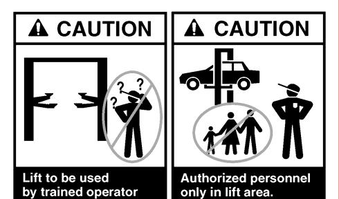
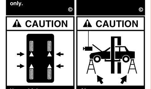
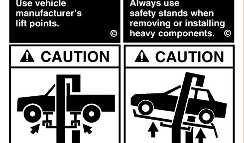
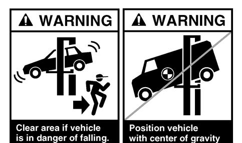
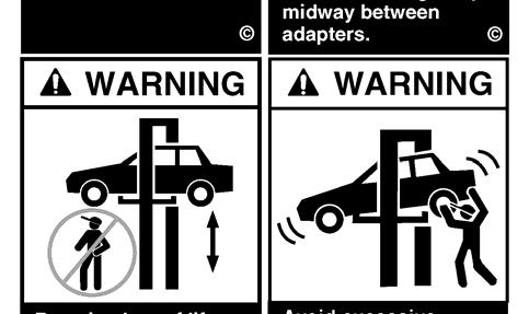
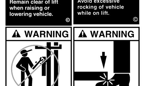
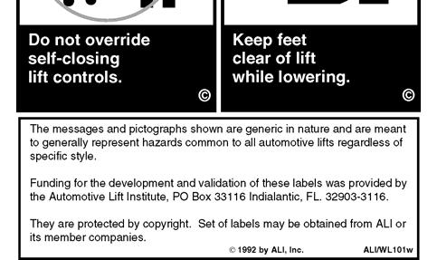
4 16. To reduce the risk of electric shock, do not use the lift when wet, do not expose the lift to rain. 17. To reduce the risk of fire, do not operate equipment in the vicinity of open containers of flammable liquids (gasoline). 18. Use the lift only as described in this manual, use only manufacturer s recommended attachments. 19. Unusual vehicles, such as limousines, RV s, and long wheelbase vehicles, may not be suitable for lifting on this equipment. If necessary, consult with the manufacturer or the manufacturer s representative. 20. The troubleshooting and maintenance procedures described in this manual can be done by the lift s owner/employer. Any other procedure should only be performed by trained lift service personnel. These restricted procedures include, but are not limited to, the following: cylinder replacement, carriage and safety latch replacement, leg replacement, overhead structure replacement. 21. Anyone who will be in the vicinity of the lift when it is in use should familiarize themselves with following Caution, Warning, and Safety related decals supplied with this lift, and replace them if the are illegible or missing: 4
5 5
6 14. Monthly Maintenance: 1. Lubricate the four inside corners of the legs with heavy duty bearing grease. 2. With lift lowered check the hydraulic fluid level. If necessary add oil as described in the Installation Instruction section of this manual 3. Check carriage latch synching: Latches should click at the same time. If necessary adjust cables as described in the Installation Instruction section of this manual. 4. Check tightness of all bolts. 5. Check anchor bolt tightness. If the anchor bolts are loose, they should be re-torqued to 90ft/lbs. Check the nuts for tightness every week for the first month, and every month afterwards. 6. Replace worn or broken parts only with lift manufacturer s parts, or their equivalent. Troubleshooting: 7. The power unit does not run: Check electrical supply breaker, or fuse. Check for activation of the travel limit switch by a tall vehicle. Check micro-switch and connections in motor control box. Check voltage to the motor. Check micro-switch and connections in the overhead switch box. 8. The power unit runs but does not raise the lift: Check the oil level. Check that the lowering valve is not stuck open. Check the connections and components on the suction side of the pump. 9. The power unit raises the lift empty, but will not lift a vehicle. Make sure the vehicle is not above the rated capacity of the lift. Make sure the vehicle is positioned properly. Clean the lowering valve by running the power unit for 30 seconds while holding the lowering valve open. Check the motor voltage. 10. Lift drifts down. Check for external leaks. Clean the lowering valve by running the power unit for 30 seconds while holding the lowering valve open. Repeat this procedure three times. Clean the check valve seat. 11. Slow Lifting and/or oil foaming up. Check that oil used meets the specification in the Installation Instruction section of this manual. Tighten all suction line fittings. 6
7 12. Anchors continually work loose If holes were drilled too large relocate the lift per the Installation Instruction section of this manual. Floor is not sufficient to provide the necessary resistance, remove an area of concrete and repour as described in the Installation Instruction section of this manual. 13. Lift does not raise and lower smoothly. Reposition vehicle for a more even weight distribution. Check the four inside corners of the two legs for roughness. Any rust or burrs must be removed with 120 grit emery cloth. Lubricate the leg corners with heavy duty bearing grease. Use a level to check the legs for vertical alignment both side to side and front to back. Shim the legs as necessary per the Installation Instruction section of this manual. Check the oil level. Make sure there is no air in the hydraulic lines, bleed system as described in the Installation Instruction section of this manual. 14. The lift will only lower approximately 1, then stops. Check that the safety latch pull rods are disengaged. If after disengagement of the pull rods, one of them moves back up as the lift is lowered, the pull rod is out of adjustment and is rubbing on the leg. Adjust the rod to clear the leg. Push down on the first bend of the rod just inside the leg. Bend the rod slightly to allow it to move freely between the leg and the carriage. Figure 1 7
8 15. At full rise the latch will not disengage and the lift cannot be lowered. If the equalization cables are out of adjustment the carriages are out of sync, and when the lift is at full rise one of the safety latches may not have the clearance to disengage and allow the lift to lower. To lower the lift Raise the lift to full height. Push In both safety latch pull rods to engage latches. Use a hydraulic jack and a length of pipe to raise the carriage with the lock which is sticking enough to disengage the safety latch. Pull the latch rod on that carriage only. Remove the jack and pipe. Pull the latch rod on the other carriage to disengage the latch. Lower the lift and remove the vehicle. Readjust the cables as described in the Installation Instruction section of this manual. 16. Power Unit will not stop running Switch is damaged, turn off power to the lift and replace switch. 15. Cylinder Replacement: 1. This task is to be performed by trained lift service personnel only. 2. Raise the lift carriages a few inches. 3. Place a 2" spacer under each carriage. 4. Lower carriages onto the spacers. 5. Do not hold the cylinder rod with anything that will damage the finish. Cylinder leaks caused by damaged rods are not covered by warranty. Hold the 1" full nut and remove the jam nut. 6. Remove the full nut. 7. Remove the pressure hose from the bottom fitting of the cylinder. Mark the inlet position on carriage. 8. Remove the return hose from the top of the cylinder. 9. Pull the rod from the carriage bottom plate. 10. Push the rod into the cylinder to prevent damage to the rod during handling. 11. Remove the cylinder from the upright by taking out the 3/4 x 5 grade 8 bolt at the top of the cylinder. 12. Reverse the procedure to replace the cylinder, being careful to position the pressure hose inlet to achieve proper orientation. 13. Bleed hydraulic system as described in the Installation Instruction section of this manual. 8
9 16. Section Installation Instructions 18. Tools required for installation: Procedure: Concrete hammer drill with 3/4" bit 11/16" open end wrench 3/4" open end wrench Torque wrench 15/16" deep socket or wrench 1-1/8" socket 13/16" open end wrench Level (18" minimum length) Vise grips Tape measure Funnel Hoist or Forklift (optional) Two 12' step ladders 1/4 drive ratchet with 5/16 socket 1. Read this manual thoroughly before installing, operating, or maintaining this lift. 2. Site Evaluation and Lift Location: Always use an architect s plan when provided. Before unpacking the lift entirely, determine if the site is adequate for the lift model being installed see figures 2 & 3 for typical bay layout and ceiling height requirements. Figure 2 9
10 Figure 3 A. Note the mainside leg has a mounting bracket on its back for the power unit. The mainside leg is typically located on the passenger side of the lift. B. Layout and mark the floor for the leg placement locations. 3. Unpack the lift. Remove the swing arms, bolt box, power unit box, and overhead beam. Save all packing hardware, as these components are necessary to complete the installation. A. Remove the ½ bolts from the packing bracket which holds the two legs together. B. Remove the top leg. Do not stand legs up, instead lay the legs flat on their backs on the floor. 10
11 4. Mount the Uprights and, if purchased, Height Extensions to the legs using the ½ NC x 2½ bolts, nuts, and washers as shown in figure 4. Figure 4 5. Carriage Placement. Disengage the latch by pulling out the latch rod at bottom of one carriage, figure 5. Slide the carriage to the leg s baseplate. Engage the latch by pushing the latch rod in. Slide the carriage up until the first click is heard. Repeat the process for the other carriage. Figure 5 11
12 6. Install hydraulic cylinders, fittings, and hoses A. Warning: When attaching hydraulic fittings with pipe threads to the cylinders use Teflon tape. DO NOT start the Teflon tape closer than 1/8 from the end of the fitting. Failure to comply may cause damage to the hydraulic system. B. Warning: When making tightening connections with flared (JIC) fittings, always follow the tightening instructions. Failure to follow these instructions may result in cracked fittings and / or leaks. Use the proper size wrench, The nut portion of the fitting is the only part that should turn during tightening. The flare seat MUST NOT turn. Screw the fittings together hand tight. Use the proper size wrench to rotate the nut portion of the fitting 2-1/2 hex flats. Back the fitting off one full turn. Again, tighten the fitting hand tight, then rotate the nut portion of the fitting 2-1/2 hex flats. C. Remove the plugs from each port on the cylinders. D. Connect a male pipe thread to male JIC elbow to the port near the rod end of each cylinder. The fittings should face away from the leg s baseplate. E. Connect the shortest hydraulic hose to the elbow on the cylinder to be used in the mainside leg. This connection should be hand-tight only. The mainside leg is identifiable by the power unit bracket and hose guides welded to it. F. Connect the longest hose to the elbow attached to the cylinder to be used in the offside leg, again hand tight. G. Connect a male pipe thread to female pipe thread bushing to the port on the cap end of each cylinder. H. Connect the ¼ airline tee to the bushing on the mainside leg cylinder. The side connection of the tee should face one of the openings in the upright. I. Connect the other ¼ airline fitting to the bushing on the capped end of the cylinder. J. Install the cylinders in the legs by attaching them to the Uprights with the 3/4" x 5" Grade 8 bolts and nuts, figure 6. The cylinder ports should be positioned pointing towards the center of the lift. 12
13 Figure 6 K. Taking care not to damage the threads, pull the cylinder rod down into the mounting hole at the base of one of the carriages. Make sure the snap ring on the cylinder rod is in the groove. Pull the rod through the hole until the snap ring contacts the carriage plate. Attach the full nut to the rod and tighten until the rod turns. Hold the full nut with a wrench and tighten a jam nut against it. Repeat for the other cylinder. Do not hold the cylinder rod in a way that could damage the finish. Cylinder leaks caused by damaged rods are not covered by warranty. 7. Leg positioning and anchoring A. Raise the Mainside leg only and position it where it is to be secured. B. The anchor bolts must be installed at least 5-11/16" from any edge or seam in the concrete C. The concrete must be at least 6 thick with a compression strength of 3,000 psi. D. Using the leg as a template, drill the eight anchor bolt holes for the Mainside Leg Only!! Use a hammer drill with a Carbide tip, 3/4" diameter, solid drill bit. The bit tip diameter should be to ANSI Standard B (.775" to.787"). Keep the drill perpendicular to the floor while drilling. Let the drill do the work. Do not apply excessive pressure. Lift the drill up and down to remove dust and reduce binding. Drill the hole completely through the slab. 13
14 Clean the dust from the hole. E. Assemble the washers and nuts onto the anchor bolts. Thread the nuts onto the anchor bolts where the tops of the nuts are just above the top of the bolts, figure 7. Using a hammer, carefully tap the anchor bolts into the concrete until the washer rests against the baseplate. Do not damage the nuts or threads. Figure 7 F. Using a level, plumb the mainside leg both side to side and front to back. Shim the leg as necessary next to and on both sides of the anchor bolts. If more than 1/2" of shimming is required, do not use the anchors and small shims provided with the lift. Use longer anchors and fabricate larger shims from steel flat, 1/4" or 1/2" thick by 2", or more, wide. G. Once the leg is plumb tighten the anchor bolts to 150 ft-lbs. Do not use an impact wrench on anchor bolts. If after tightening the anchor supplied with the lift extends more than 2-1/4 above the floor the anchor does not have enough embedment. If an anchor will not reach 150 ft-lbs or does not have enough embedment or adequate spacing cannot be achieved, replace the concrete under the leg with a 5 X 5 X 6 thick pad of 3,000 psi concrete keyed under the existing floor. Let the concrete cure before reinstalling the lift. H. Recheck the leg s plumbness after tightening the anchor bolts. Add shims if necessary. I. Raise the offside leg and position it where it is to be located. Do not drill holes for anchors. 14
15 8. Overhead assembly A. Using a ¼ drive ratchet and 5/16 socket, connect two #10-18 X 1/2 self-tapping screws through the holes in the overhead switch assembly into the overhead beam as shown in figure 8. Figure 8 B. Slide the end of the padded switchbar without a hole in it through the slot in the overhead switch assembly. Connect the padded switchbar to the overhead beam using a #10-18 X 1-3/4 self-tapping screw and spacer, figure 9. Figure 9 15
16 C. Attach the overhead beam to the uprights. Raise the overhead beam and secure it to the top of the uprights using eight 1/2 x 2-1/2 bolts, figure Anchoring offside leg Figure 10 For extended height models raise the overhead beam and secure it to the top of the Height Extensions using four 1/2 x 2-1/2 bolts at each end. A. Using a level check the alignment and plumbness of the entire structure. Plumb the offside leg both side to side and front to back. B. The base of the leg may vary slightly from the preliminary layout, as it is more important that the leg be perpendicular to the floor and parallel to the other leg. C. Install the anchor bolts and shim the base as described in the earlier Leg positioning and anchoring step. 16
17 10. Assemble carriage cables A. The carriages should be resting on the same safety rack tooth. Measure the height above the baseplate for each carriage. The measurements should be within 3/8" of each other. Make a note of the two measurements. B. Standing between the two legs looking at either carriage, push one end of a cable down through the right-rear hole in the top of the carriage until the cable hits the floor. C. Attach a 3/4 nylon insert nut with an SAE washer to the end of the cable. Connect the nut to the cable so that approximately 1/8 of the cable end sticks past the end of the nut. D. Running the cables, figure 11. Thread the other end of the cable up through the upright, Over the rightmost pulley at the top of the lift, Over to the leftmost overhead pulley on the other side of the lift, Down through the left rear hole in the top of the carriage, Around the pulley in the bottom of the leg, Up through the left-front hole in the top of the carriage. E. Secure the cable end with a 3/4 nylon insert nut and SAE washer. Do not tighten the cable at this time. F. Repeat the process for the other cable, taking care not to cross them. G. Take out the slack, but do not tighten, both cables by turning down the nuts on the top of each carriage top. Use vise grips to hold the cable end, but be very careful not to damage the threads. H. The carriages must remain at the same lock position while the cables are being tightened. Overtightening of one cable could raise the carriage in the opposite leg and cause the carriage safety latches to be out of sync. I. Alternately tighten the cable nuts at both carriages until the cables are tightened. Correct tension in the cables is indicated by approximately 1/4" deflection on the cable in the leg when pulled at its midpoint. J. Measure and compare the carriage heights to the earlier measurement, or check that the safety latch pull rod will not disengage to verify that neither carriage has been raised. If a carriage has been raised more than 1/8", loosen the cables and repeat the procedure. 17
18 K. If the cables are installed correctly, both carriages will raise together. If equipment capable of lifting the carriages is readily available, lift one of them just enough to pull out the safety latch pull rods under both carriages and carefully lower to the ground. This will simplify the cylinder bleeding procedure. Figure Mounting the power unit. Attach four 5/16" x 1-1/4" bolts to the highest two and lowest two holes in the mounting bracket with 5/16" plain nuts. Attach the power unit, to these bolts and secure with 5/16" nylon insert nuts. 18
19 12. Hydraulic system, figure 12. A. The right side of the power unit from the controls has one open port. Attach the o-ring elbow to this port with the open end up. B. Connect the remaining pressure hose to the o-ring elbow on the power unit. Run the hose up through the hose guides welded to the back of the leg. Connect the male JIC tee to the hose so that the other two ends of the tee are running through the overhead and down the leg. C. Pull the hose from the mainside cylinder up and connect it to the tee. D. Run the offside cylinder hose up the offside leg, through the overhead, and connect it to the tee. E. To prevent the carriages from rubbing the hoses, pull the hoses upward taking out any slack between the cylinder fitting port and the cylinder mount. Secure the hoses to the mainside cylinder with wire tie around the tee and the cylinder. Secure the hose to the offside cylinder at approximately the same height with a wire tie. F. Any excess hose should be taken up at the corners between the legs and the overhead. Once the slack in the hoses has been properly taken up, secure the hoses in place with wire ties. G. Add fluid. Remove the fill level screw near the top of the power unit tank. Remove the fill-cap from the tank and fill with Dexron III ATF or petroleum base hydraulic oil, ISO-32, non foaming, non detergent, such as Mobil DTE 24 or Texaco HD 32, until fluid reaches the bottom of the return line port adjustable elbow. Figure 12 19
20 13. Electrical. A. Have a certified electrician establish V, single phase, 60 Hz., 20 amp, power supply to motor and overhead switch, figure 13. Use separate circuits for each power unit. Single phase motor cannot be run on 50 Hz. line without modifications in the motor. Figure 13 20
21 14. Bleeding the hydraulic system, figure 12. A. Loosen the connections between the hoses and fittings attached to the cylinders. Do not loosen the connections between the fittings and the cylinders themselves. B. Run the power unit until fluid appears at the mainside cylinder port. Tighten that hose connection. C. Run the power unit until fluid appears at the offside cylinder port and there is no more air. Tighten that hose connection. D. Lower the lift to the ground. If the lift is on the safety latches, raise the lift enough to disengage the latches and then lower. E. If the carriages were on the ground when the bleeding process was begun, no further bleeding is required. If not, repeat the previous steps for bleeding the hydraulic system. F. Add fluid to the system as previously described. 15. Connecting the return lines, figure 12. A. Take special care not to kink the plastic return lines. B. From the power unit run one end of the ¼ plastic tubing up through the hose guides and connect it to the tee attached to the top of the mainside cylinder. C. Measure out enough tubing to adequately reach the fitting on the back of the power unit tank. Cut the tubing and connect it to the fitting. D. Connect one end of the remaining tubing to the open port in the tee at the top of the mainside cylinder. E. Run the free end of the tubing up the mainside column, through the overhead and down the offside column. Cut off excess tubing and connect the hose to the fitting on the top of the offside cylinder 21
22 16. Assembling the arms and arm restraints A. Install the swing arms with the swing arm pins, figure 14. B. Install the swing arm restraints, figure 15. Figure 14 Figure Lubricate the four inside corners of both legs with heavy duty bearing grease. 22
23 18. Final Adjustments A. If any problems are encountered, do not proceed with subsequent steps. Instead, resolve the problem before proceeding by referencing the Troubleshooting portion of the Owner s Manual section of this manual. B. Raise the lift to full height. Lower the lift onto the safety latches. Raise the carriages, pull out both latch pull rods, and lower the lift to the ground. C. Raise the lift empty to the top of its travel and lower it the floor three (3) times to remove the remaining air from the hydraulic system. D. The latches should click together as the lift is being raised. E. When the carriages are lowered onto the locks, neither pull rod should be capable of being pulled out. F. The first time a vehicle is placed on the lift, raise it no higher than three feet. Lower the vehicle onto the safety latches. Raise the lift a few inches and pull out both latch pull rods then lower the vehicle to the floor. G. Raise the vehicle to full height and lower the carriages onto the safety latches. Lower the vehicle to the floor. H. After cycling the lift ten times with a vehicle on it, recheck the tightness of the anchors to at least 150 ft-lbs. 23
24 PARTS BREAKDOWN 1) BOLT BOX ) CABLE KIT STANDARD HEIGHT EXTENDED HEIGHT ) HYDRAULIC KIT STANDARD HEIGHT EXTENDED HEIGHT ) MAINSIDE LEG ) OFFSIDE LEG ) CARRIAGE ASSEMBLY ) WIPE OUT ) SAFETY LATCH ) ARM RESTRAINT PAWL ) ACTUATOR PIN ) ARM RESTRAINT SPRING ) PULL ROD ) 3/8 FLAT WASHER ) 1-1/8NF NYLOC NUT ) 1-1/8 SAE WASHER ) ¼ ROLL PIN X 1-1/ ) 3/16 PAL NUT ) LATCH SPRING ) 3/8 KLIP RING ) ¾ KLIP RING ) CARRIAGE WELDMENT ) SWING ARM ASSEMBLY ) UPRIGHT WELDMENT ) OVERHEAD WELDMENT ) 2 EXTENSION STANDARD HEIGHT - EXTENDED HEIGHT ) SNAP RING, 1-3/8" EXTERNAL ) 5" CABLE SHEAVE ) CYLINDER, 3" x 68" STROKE ) RUB BLOCK ) POWER UNIT ) HHCS G5 1/2"-13NC x 2-1/2 LG ) HEX NUT 1/2"-13NC ) FLAT WASHER, 1/2"
25 1. Section 3 2. Parts Breakdown Figure 15 25
26 1 Offside Leg /2-13 X 3/4 HHCS Grade Mainside Leg /2 Lock Washer Shim Arm Pin /4" X 5-1/2" Anchor Bolt Overhead Weldment Power Unit Overhead Switch /16-18 Hex Nut Switch Bar Spacer /16-18 Nylon Insert Lock Nut HWHTS Type F, X 1/2" /16-18 X 1-1/4" HHCS Grade HWHTS Type F X 1-3/4" Cylinder Padded Overhead Switch Bar /4-16 Nylon Insert Lock Nut Rub Block /4-16 X 5 HHCS Grade Carriage Assembly /4" SAE Washer Carriage Weld " Hex Nut Latch Weldment " Hex Jam Nut Latch Wipeout Upright Latch Pivot Extension /32 X 1-1/2 Cotter Pin /8 Snap Ring X 3 HHCS Grade " Cable Sheave " Washer /2-13 X 2-1/2 HHCS Grade /8" Washer /2-13 Hex Nut Latch Pull Rod /2 Washer Latch Spring NA NA 60 3/16 Cap Nut Cable 61 Arm Restraint Spring Standard Height Pull Loop ' Extended Height Restraint Pin Offside Return Line Fitting Restraint Spring /4" Return Line Gear Block Mainside Return Line Tee Restraint Gear /8" Bushing to 1/4" NPT Bushing /8-16NC x 1-1/2 lg. HHCS & Lock Washer 28 9/16 O-Ring to 3/8 JIC Elbow /8 JIC Tee /8 JIC to 3/8 NPT Elbow Power Unit Hose 32 Standard Height ' Extended Height Mainside Hose 33 Standard Height ' Extended Height Offside Hose 34 Standard Height ' Extended Height " Wire Tie Swing Arm Assembly Swing Arm Slider Weldment Swing Arm Tube Weldment
27 Figure 16 27
TWO POST LIFT INSTALLATION AND OWNERS MANUAL. January 2008 rev. E I MAN
 TWO POST LIFT INSTALLATION AND OWNERS MANUAL DP15, DP15-2 Capacity 15,000 lbs. January 2008 rev. E 1. TABLE OF CONTENTS 2. Important Information.. 2 3. Section 1 Owner s Manual Safety Instructions... 3
TP10KACD REV A
 TP10KACD 10, 000l bcapaci t y TwoPostAsymmet r i caut oli f t REV A-061813 Table of contents Important Information Section 1 Owner s Manual Safety Instructions Monthly Maintenance Troubleshooting Section
TWO POST LIFT INSTALLATION AND OWNERS MANUAL Capacity 10,000 lbs.
 TWO POST LIFT INSTALLATION AND OWNERS MANUAL Capacity 10,000 lbs. May 2009 All rights reserved. CO7378.2 IN60005 Rev. - 5/7/2009 TABLE OF CONTENTS Important Information...2 Section 1 Owner s Manual Safety
TWO POST LIFT INSTALLATION AND OWNERS MANUAL Capacity 10,000 lbs.
 TWO POST LIFT INSTALLATION AND OWNERS MANUAL Capacity 10,000 lbs. October 2012 by Vehicle Service Group All rights reserved. CO8347 IN60009 Rev. H 10/18/2012 TABLE OF CONTENTS Important Information...2
ATD2P11BS. Two-Post Clear Floor Bi-Symmetric Automotive Lift. Installation & Operation Manual. 11,000 lbs. Capacity. (2,750 lbs.
 Two-Post Clear Floor Bi-Symmetric Automotive Lift 11,000 lbs. Capacity (2,750 lbs. Max per Arm) Installation & Operation Manual 1. Safety Information 1.1 Note, Caution and Warning 1.2 Important Information
SCISSOR LIFT Model MR6K-38 /161108A 6,000lb Capacity Operation Manual
 SCISSOR LIFT Model MR6K-38 /161108A 6,000lb Capacity Operation Manual (Version A) 2009. Apr. CONTENT 1. Safety Note, Caution and Warning Important Information Safety Instructions 2. Technical Manual Product
Installation Instructions Capacity 10,000 lbs. (100 Series Lift)
") Installation Instructions Capacity 10,000 lbs. (100 Series Lift) IMPORTANT Reference ANSI/ALI ALIS, Safety Requirements for Installation and Service of Automotive Lifts before installing lift. OPERATING
Installation Instructions Capacity 10,000 lbs. (100 Series Lift) IMPORTANT Reference ANSI/ALI ALIS, Safety Requirements for Installation and Service of Automotive Lifts before installing lift. OPERATING
TP12KC-DX. Two Post Clear Floor. Automotive Lift. 12,000 lb. Capacity. (3,000 lbs. Max Capacity per Arm) Installation & Operation Manual
 Installation & Operation Manual") Two Post Clear Floor Automotive Lift 12,000 lb. Capacity (3,000 lbs. Max Capacity per Arm) Installation & Operation Manual IMPORTANT!! READ MANUAL THOROUGHLY BEFORE INSTALLING, OPERATING, SERVICING OR
Two Post Clear Floor Automotive Lift 12,000 lb. Capacity (3,000 lbs. Max Capacity per Arm) Installation & Operation Manual IMPORTANT!! READ MANUAL THOROUGHLY BEFORE INSTALLING, OPERATING, SERVICING OR
Installation Instructions Capacity 10,000 lbs. DP10 (200 Series Lift)
") Installation Instructions Capacity 10,000 lbs. DP10 (200 Series Lift) IMPORTANT Reference ANSI/ALI ALIS, Safety Requirements for Installation and Service of Automotive Lifts before installing lift. OPERATING
Installation Instructions Capacity 10,000 lbs. DP10 (200 Series Lift) IMPORTANT Reference ANSI/ALI ALIS, Safety Requirements for Installation and Service of Automotive Lifts before installing lift. OPERATING
Lifting height 5.5" - 72" with adapters " Height overall 165" Width between columns 122" Drive through 109" Width overall 151.
 Model Number TP12KC-D Capacity 12,000 lbs. Lifting height 5.5" - 72" with adapters 79.625" Height overall 165" Width between columns 122" Drive through 109" Width overall 151.125" Arm extension 37.5" -
MR6K lb Capacity Portable Mid-Rise Scissor Lift. Operation Manual
 MR6K-38 6000 lb Capacity Portable Mid-Rise Scissor Lift Operation Manual 6,000 LB. PORTABLE MID-RISE FRAME LIFT A comfortable 38 working height, twin cylinders and double safety locks make this portable
Installation Instructions
 Installation Instructions 2-Post Capacity 12,000 lbs. OPERATING CONDITIONS Lift is not intended for outdoor use and has an operating ambient temperature range of 41-104 F (5-40 C) IMPORTANT Reference ANSI/ALI
Challenger Lifts, Inc. MODEL 12000
 Challenger Lifts, Inc. MODEL 12000 TWO POST SURFACE MOUNTED LIFT OPERATION, INSTALLATION & MAINTENANCE MANUAL IMPORTANT READ THIS MANUAL COMPLETELY BEFORE INSTALLING OR OPERATING THE LIFT 200 CABEL STREET,
Challenger Lifts, Inc. MODELS & 18000
 Challenger Lifts, Inc. MODELS 15000 & 18000 TWO POST SURFACE MOUNTED LIFT OPERATION, INSTALLATION & MAINTENANCE MANUAL IMPORTANT READ THIS MANUAL COMPLETELY BEFORE INSTALLING OR OPERATING THE LIFT 200
READ THIS MANUAL BEFORE INSTALLATION AND/OR OPERATION! WARNING:
 1 READ THIS MANUAL BEFORE INSTALLATION AND/OR OPERATION! This is a vehicle lift operation manual and no attempt is made or implied herein to instruct the user in lifting methods particular to an individual
If facility voltage is different, refer to set-up instructions. IMPORTANT This lift is wired and adjusted to operate at 230 volts.
 MODEL 40/50K Installation And Owner s Manual (000Series) Capacity 40,000 lbs. (20,000 lbs. per axle) Capacity 50,000 lbs. (25,000 lbs. per axle) Four Post Surface Mounted Lift IMPORTANT This lift is wired
IMPORTANT INFORMATION
 TABLE OF CONTENTS IMPORTANT INFORMATION... 2 LIFT AREA LAYOUT INFORMATION... 3 TOOLS and EQUIPMENT REQUIRED FOR INSTALL... 4 INSTALLATION PROCEDURE... 5 FOUNDATION and ANCHORING REQUIREMENTS... 6 DEFINITION
MODEL QMR6 PORTABLE MID-RISE LIFT 6,000 lb Capacity 1500 lb Per Arm INSTALLATION, OPERATION AND MAINTENANCE MANUAL
 MODEL QMR6 PORTABLE MID-RISE LIFT 6,000 lb Capacity 1500 lb Per Arm INSTALLATION, OPERATION AND MAINTENANCE MANUAL IMPORTANT!!! READ THIS MANUAL COMPLETELY BEFORE INSTALLING OR OPERATING THE LIFT 200 CABEL
Model OE Four Post Surface Mounted Lift. Office / Fax IMPORTANT: READ THIS MANUAL COMPLETELY BEFORE
 Four Post Surface Mounted Lift Model OE-40000 Open Front (,000 lb Capacity) 0 Cabel Street, P.O. Box 3944 Louisville, Kentucky 40-3944 Email:sales@challengerlifts.com Web site:www.challengerlifts.com Office
CONTENTS. Product Features and Specifications Installation Requirement Installation Exploded View Operation Instruction...
 1 CONTENTS Product Features and Specifications... 3 Installation Requirement... 5 Installation... 6 Exploded View... 20 Test... 22 Operation Instruction... 25 Maintenance... 26 Trouble Shooting... 27 Parts
Installation Instructions X-Force UTV Lift (000 Series) Capacity 2,275 lbs (1,035 kg)
 Capacity 2,275 lbs (1,035 kg)") Installation Instructions X-Force UTV Lift (000 Series) Capacity 2,275 lbs (1,035 kg) Read entire manual before assembling, installing, operating, or servicing this equipment. LP20640 IN20793 September
Installation Instructions X-Force UTV Lift (000 Series) Capacity 2,275 lbs (1,035 kg) Read entire manual before assembling, installing, operating, or servicing this equipment. LP20640 IN20793 September
INSTALLATION, OPERATION & MAINTENANCE MANUAL
 INSTALLATION, OPERATION & MAINTENANCE MANUAL Two Post Surface Mounted Lift MODEL X10 10,000 LBS. CAPACITY 2500 LBS. PER ARM 200 Cabel Street, P.O. Box 3944 Louisville, Kentucky 40201-3944 Email:sales@challengerlifts.com
Installation, Operation & Maintenance Manual. Surface Mounted Lift 10,000 LBS. CAPACITY 2500 LBS. PER ARM
 Installation, Operation & Maintenance Manual VersymmetricTM Two Post Surface Mounted Lift MODEL CL10 10,000 LBS. CAPACITY 2500 LBS. PER ARM 200 Cabel Street, P.O. Box 3944 Louisville, Kentucky 40201-3944
Model Q4P12E and Q4P12X
 INSTALLATION, OPERATION & MAINTENANCE MANUAL Four Post Surface Mounted Lift Model Q4P2E and Q4P2X Closed Front (2,000 lb Capacity) 200 Cabel Street, P.O. Box 3972 Louisville, Kentucky 4020-3972 Email:sales@Qualitylifts.com
Four Post Surface Mounted Lift Capacity 14,000 lbs. (7,000 lbs. per axle)
") Four Post Surface Mounted Lift Capacity 14,000 lbs. (7,000 lbs. per axle) July 2014 by Vehicle Service Group. All rights reserved. LP60032 CO8906.8 IN60032 Rev. A 7/25/2014 INSTALLATION INSTRUCTION 4'-6"
Four Post Surface Mounted Lift Capacity 14,000 lbs. (7,000 lbs. per axle) July 2014 by Vehicle Service Group. All rights reserved. LP60032 CO8906.8 IN60032 Rev. A 7/25/2014 INSTALLATION INSTRUCTION 4'-6"
Installation, Operation & Maintenance Manual. Four Post Surface Mounted Lift. Model Open Front (15,000 lb Capacity)
") Installation, Operation & Maintenance Manual Four Post Surface Mounted Lift Model 405 Open Front (5,000 lb Capacity) 23 South Park Rd Louisville, Kentucky 40206 Email:sales@challengerlifts.com Web site:www.challengerlifts.com
Installation, Operation & Maintenance Manual Four Post Surface Mounted Lift Model 405 Open Front (5,000 lb Capacity) 23 South Park Rd Louisville, Kentucky 40206 Email:sales@challengerlifts.com Web site:www.challengerlifts.com
CONTENTS. Product Features and Specifications...1. Installation Requirement...3. Steps of Installation...4. Exploded View Test Run...
 TP10AS 2-POST LIFT CONTENTS Product Features and Specifications...1 Installation Requirement...3 Steps of Installation...4 Exploded View...24 Test Run....28 Operation Instruction...29 Maintenance...30
( Series) Capacity 18,000 lbs. (9,000 lbs. per axle) Four Post Surface Mounted Lift Maximum Wheelbases: 194" & 230" Minimum Wheelbase: 126"
 Capacity 18,000 lbs. (9,000 lbs. per axle) Four Post Surface Mounted Lift Maximum Wheelbases: 194 & 230 Minimum Wheelbase: 126") LP20111 March 2015 by Vehicle Service Group. IN20195 All rights reserved. CO9223.5 Rev. L 3/24/2015 SM18 (000-017 Series) Capacity 18,000 lbs. (9,000 lbs. per axle) Four Post Surface Mounted Lift Maximum
LP20111 March 2015 by Vehicle Service Group. IN20195 All rights reserved. CO9223.5 Rev. L 3/24/2015 SM18 (000-017 Series) Capacity 18,000 lbs. (9,000 lbs. per axle) Four Post Surface Mounted Lift Maximum
MODEL CL10. Versymmetric Two Post. Surface Mounted Lift. Installation, Operation & Maintenance Manual
 Installation, Operation & Maintenance Manual Versymmetric Two Post Surface Mounted Lift MODEL CL10 10,000 LBS. CAPACITY 2500 LBS. PER ARM 200 Cabel Street, P.O. Box 3944 Louisville, Kentucky 40201-3944
Two Post Surface Mounted Lift 10,000 LBS. CAPACITY 2500 LBS. PER ARM
 INSTALLATION, OPERATION & MAINTENANCE MANUAL Two Post Surface Mounted Lift MODEL LE10 10,000 LBS. CAPACITY 2500 LBS. PER ARM 2311 South Park Rd Louisville, Kentucky 40219 Email:sales@challengerlifts.com
Two Post Surface Mounted Lift 12,000 LBS. CAPACITY 3000 LBS. PER ARM
 INSTALLATION, OPERATION & MAINTENANCE MANUAL Two Post Surface Mounted Lift MODEL EELR537A 12,000 LBS. CAPACITY 3000 LBS. PER ARM Snap-On Equipment 309 Exchange Avenue, Conway, Arkansas, 72032 Tel: 501-450-1500
Model Q4P12E and Q4P12X
 INSTALLATION, OPERATION & MAINTENANCE MANUAL Four Post Surface Mounted Lift Model Q4P2E and Q4P2X Closed Front (2,000 lb Capacity) 200 Cabel Street, P.O. Box 3944 Louisville, Kentucky 4020-3944 Email:sales@Qualitylifts.com
SPO15, SPO18 I N S T A L L A T I O N I N S T R U C T I O N S
 SPO15, SPO18 Sprinter SPO15 (3A0 Lifts) Capacity 11,000 lbs. Standard SPO15 (300 Series Lifts) Capacity 15,000 lbs. Standard SPO18 (300 Series Lifts) Capacity 18,000 lbs. SPO15 (31A0 Lifts) Capacity 14,300
9,000 POUND TWO-COLUMN AUTOMOTIVE LIFT Model: NW-2-9KFP MANUAL
 9,000 POUND TWO-COLUMN AUTOMOTIVE LIFT Model: NW-2-9KFP MANUAL 1 9,000 POUND CAPACITY MODEL: NW-2-9KFP TWO-COLUMN AUTOMOTIVE LIFT READ THIS ENTIRE MANUAL BEFORE OPERATION BEGINS RECORD BELOW THE FOLLOWING
CONTENTS. Product Features and Specifications Installation Requirement Steps of Installation 4. Exploded View Test Run...
 CONTENTS Product Features and Specifications... 1 Installation Requirement... 3 Steps of Installation 4 Exploded View... 14 Test Run... 16 Operation Instruction... 19 Maintenance... 20 Trouble Shooting...
2-Post Lift Operations and Maintenance Manual
 2-Post Lift Operations and Maintenance Manual Table Of Contents Safety Instructions... 2 Owner/Employer Responsibilities / Operating Conditions... 3 Operating Instructions... 4 Maintenance Instructions...
INSTALLATION, OPERATION & MAINTENANCE MANUAL
 INSTALLATION, OPERATION & MAINTENANCE MANUAL Four Post Surface Mounted Lift Model 4P14EFX and 4P14XFX Closed Front (14,000 lb Capacity) 200 Cabel Street, P.O. Box 3944 Louisville, Kentucky 40201-3944 Email:sales@challengerlifts.com
SM88 I N S T A L L A T I O N I N S T A L L A T I O N I N S T R U C T I O N S I N S T R U C T I O N S
 I N S T A L L A T I O N I N S T R U C T I O N S January 2005 by Rotary Lift. CO6167.2 IN30071 Rev. B 01/20/2005 I N S T A L L A T I O N I N S T R U C T I O N S LP30072 SM88 (300 Series) Four Post Surface
AR123/SM123 I N S T A L L A T I O N I N S T A L L A T I O N I N S T R U C T I O N S I N S T R U C T I O N S
 February 2005 by Rotary Lift. All rights reserved. CO6167.3 I N S T A L L A T I O N I N S T R U C T I O N S IN30069 Rev. E 02/10/2005 I N S T A L L A T I O N I N S T R U C T I O N S LP30068 AR123/SM123
MIDRISE MODEL SM60F_1 // SM60F_A 6,500 LB. CAPACITY
 INSTALLATION and OPERATION MANUAL READ THIS INSTRUCTION MANUAL THOROUGHLY BEFORE INSTALLING, OPERATING, SERVICING OR MAINTAINING THE LIFT. SAVE THIS MANUAL. NOV 2007 REV.B MIDRISE MODEL SM60F_1 // SM60F_A
Floor Plate Style Lift And Overhead Beam Style Lift. Two Post Lift
 Floor Plate Style Lift And Overhead Beam Style Lift 9,000 POUND Two Post Lift ASSEMBLY & OPERATION INSTRUCTION TABLE OF CONTENTS Important Note Page 3 Definition Page 4 Preparation and General Information
MODEL CL10. Versymmetric Two Post. Surface Mounted Lift. Installation, Operation & Maintenance Manual
 Installation, Operation & Maintenance Manual Versymmetric Two Post Surface Mounted Lift MODEL CL10 10,000 LBS. CAPACITY 2500 LBS. PER ARM 200 Cabel Street, P.O. Box 3944 Louisville, Kentucky 40201-3944
9,000 LBS. CAPACITY 2250 LBS. PER ARM
 INSTALLATION NSTALLATION,, OPERATION O & MAINTENANCE M MANUAL & M VersymmetricTM Two Post Surface Mounted Lift MODEL CL9 9,000 LBS. CAPACITY 2250 LBS. PER ARM 200 Cabel Street, P.O. Box 3944 Louisville,
Two Post Surface Mounted Lift 12,000 LBS. CAPACITY 3000 LBS. PER ARM
 INSTALLATION, OPERATION & MAINTENANCE MANUAL Two Post Surface Mounted Lift MODEL Q12 12,000 LBS. CAPACITY 3000 LBS. PER ARM 200 Cabel Street, P.O. Box 3944, Louisville, Kentucky 40206 Email:sales@qualitylifts.com
WHIP INDUSTRIES, INC.
 WHIP INDUSTRIES, INC. WFP30R, WFP30R-E & WFP30R-EE STD., EXT. & E-EXT. 30,000 LBS CAPACITY FOUR POST ABOVE GROUND LIFT INSTALLATION INSTRUCTIONS & MANUAL WHIP INDUSTRIES, INC 3010 S MAIN ST. FORT WORTH,
MODEL CL10. VersymmetricTM Two Post. Surface Mounted Lift. Installation, Operation, & Maintenance Manual
 Installation, Operation, & Maintenance Manual VersymmetricTM Two Post Surface Mounted Lift MODEL CL10 WITH DUAL PENDANT CONTROL 10,000 LBS. CAPACITY 2500 LBS. PER ARM 200 Cabel Street, P.O. Box 3944 Louisville,
Atlas PV-9WP Addendum
 Atlas PV-9WP Addendum 9,000 lb. Capacity Two-Post Overhead Lift The Atlas PV-9WP above ground hoist is 6 inches wider than the Atlas PV-9P, giving it an overall width of 141 (11 9 ) and a drive thru width
CONTENTS. Product Features and Specifications...1. Installation Requirement Steps of Installation.. 5. Exploded View Test Run...
 CONTENTS Product Features and Specifications...1 Installation Requirement... 3 Steps of Installation.. 5 Exploded View...18 Test Run...21 Operation Instruction...22 Maintenance... 23 Trouble Shooting...
It is the shop owner's responsibility to train all operators in lift operation and safety.
 2 Your new lift will provide years of dependable service if installed, operated and maintained properly. Read and be prepared to follow all safety, installation, operation, and maintenance instructions
ATTENTION. 1. Do not attempt to use the power unit to extend your cylinder. This must be done manually.
 NSS8XLT Installation Manual ATTENTION By following the instructions in this manual you can save yourself much time, frustration and money. The installation of your lift will take 4-5 hours. Do not rush.
MODEL Two Post Surface Mounted Lift. Office / Fax Installation, Operation & Maintenance Manual
 Installation, Operation & Maintenance Manual Two Post Surface Mounted Lift MODEL 15000 15,000 LB CAPACITY - 3750 LB PER ARM MODEL 18000 18,000 LB CAPACITY 4500 LB PER ARM 200 Cabel Street, P.O. Box 3944
MODEL QFP09. Two Post Surface Mounted Lift. Installation, Operation & Maintenance Manual. Office / Fax
 Installation, Operation & Maintenance Manual Two Post Surface Mounted Lift MODEL QFP09 9,000 LBS. CAPACITY 2,250 LBS. PER ARM 200 Cabel Street, P.O. Box 3972 Louisville, Kentucky 40201-3972 Email:sales@qualitylifts.com
Models Q4P07. Four Post Surface Mounted Lift. Installation, Operation & Maintenance Manual IMPORTANT: READ THIS MANUAL COMPLETELY BEFORE
 Installation, Operation & Maintenance Manual Four Post Surface Mounted Lift Models Q4P07 (7,000 lb Capacity) 200 Cabel Street, P.O. Box 3972, Louisville, Kentucky 40201-3972 Email:sales@qualitylifts.com
10K ALL-IN-ONE 2 POST V-SERIES 42010DSA 42010VSA
 INSTALLATION and OPERATION MANUAL 10K ALL-IN-ONE 2 POST V-SERIES 42010DSA 42010VSA READ THIS INSTRUCTION MANUAL THOROUGHLY BEFORE INSTALLING, OPERATING, SERVICING OR MAINTAINING THE LIFT. SAVE THIS MANUAL.
Read this entire manual before operation begins.
 Read this entire manual before operation begins. Record below the following information which is located on the serial number data plate. Serial No. Model No. Date of Installation Contents Specifications.............
Models Q4P09H & Q4P09X
 Installation, Operation & Maintenance Manual Four Post Surface Mounted Lift Models Q4P09H & Q4P09X (9,000 lb Capacity) 200 Cabel Street, P.O. Box 3944 Louisville, Kentucky 40201-3944 Email:sales@qualitylifts.com
EZ LINER EXPRESS USERS MANUAL
 EZ LINER EXPRESS 2013 Vehicle Service Group CHIEF'S LIMITED ONE-YEAR WARRANTY & LIABILITY Chief Automotive Technologies warrants for one year from date of installation and/or purchase any components of
INSTALLATION and OPERATION MANUAL
 INSTALLATION and OPERATION MANUAL 10K 2N1 2 POST V-SERIES SV210S - R/B/M,1/3 D210S - R/B/M,1/3 READ and SAVE THIS INSTRUCTION MANUAL JUNE 2007 6-3255 Table of Contents 1.0 SAFETY AND OPERATING INSTRUCTIONS...3
CR30 Installation Instruction Capacity 30,000 lbs. (15,000 lbs. per axle) 235 /271 /308 Wheelbases 140 Minimum Wheelbase
 235 /271 /308 Wheelbases 140 Minimum Wheelbase") CR0 Installation Instruction Capacity 0,000 lbs. (,000 lbs. per axle) /7 /08 Wheelbases 40 Minimum Wheelbase January 009 CO70 INS0449 Rev. - /08/009 Required Clearances REAR 8' 0" Min. To Nearest Obstruction
CR0 Installation Instruction Capacity 0,000 lbs. (,000 lbs. per axle) /7 /08 Wheelbases 40 Minimum Wheelbase January 009 CO70 INS0449 Rev. - /08/009 Required Clearances REAR 8' 0" Min. To Nearest Obstruction
T R I N S I N S U C N S
 R O TA R Y V A L I D A T E D CERTIFIED B Y E L T SPOA7, SPOA9, SPO9 Two Post Surface Mounted Lift (200 Series Lifts) SPOA7 Capacity 7,000lbs. SPOA9 Capacity 9,000lbs. 1750 lbs. per arm 2250 lbs. per arm
Models PR-12F PR-12C PR-15C SURFACE MOUNTED TWO-POST LIFTS INSTALLATION AND OPERATION MANUAL
 Forward this manual to all operators. Failure to operate this equipment as directed may cause injury. INSTALLATION AND OPERATION MANUAL SURFACE MOUNTED TWO-POST LIFTS Models PR-12F PR-12C PR-15C Keep this
BLAZER 9000 LUBE LIFT OPERATOR AND PARTS MANUAL
 BLAZER 9000 LUBE LIFT OPERATOR AND PARTS MANUAL Blazer 9000 Lube Lift Operator s Manual Note: Instructions must be read thoroughly before installing, operating, or maintaining the lift. Devon Lube Center
9,000 POUND TWO-COLUMN AUTOMOTIVE LIFT. Model: NW-2-9KACD MANUAL
 9,000 POUND TWO-COLUMN AUTOMOTIVE LIFT Model: NW-2-9KACD MANUAL 1 9,000 POUND CAPACITY MODEL: NW-2-9KACD TWO-COLUMN AUTOMOTIVE LIFT READ THIS ENTIRE MANUAL BEFORE OPERATION BEGINS RECORD BELOW THE FOLLOWING
Read this entire manual before operation begins.
 Read this entire manual before operation begins. Record below the following information which is located on the serial number data plate. Serial No. Model No. Date of Installation Contents Specifications.............
Parts Breakdown Capacity 10,000 lbs. (4,536 kg.) (400 Series Lift)
 (400 Series Lift)") Parts Breakdown Capacity 10,000 lbs. (4,53 kg.) (400 Series Lift) LP002 August 201 by Vehicle Service Group. All rights reserved. CO57.4 PB002 Rev. M //201 ITEM PART# DESCRIPTION 1 TP10-1000 R.H. Column
Parts Breakdown Capacity 10,000 lbs. (4,53 kg.) (400 Series Lift) LP002 August 201 by Vehicle Service Group. All rights reserved. CO57.4 PB002 Rev. M //201 ITEM PART# DESCRIPTION 1 TP10-1000 R.H. Column
AUG 2011, REV.B
 6-4041 AUG 2011, REV.B 1. 1 2. OWNER / EMPLOYER OBLIGATIONS 1. The Owner/Employer shall ensure that lift operators are qualified and that they are trained in the safe use and operation of the lift using
INSTALLATION and OPERATION MANUAL
 INSTALLATION and OPERATION MANUAL AC2012S 12,000 12,000 LB. LB. (SYMMETRICAL) READ and SAVE THIS INSTRUCTION MANUAL P.O. Box 15540 Richmond, VA 23227 804-798-8922 www.accu-turn.com 1-800-551-2228 APR 2004
INSTALLATION MANUAL & OPERATION INSTRUCTIONS. OVERHEAD CAR LIFT 2-POST LIFT AUTO HOIST APlusLift HW-10KOH
 INSTALLATION MANUAL & OPERATION INSTRUCTIONS OVERHEAD CAR LIFT 2-POST LIFT AUTO HOIST APlusLift HW-10KOH 1 READ THIS MANUAL COMPLETELY BEFORE INSTALLING LIFT!!! DISTRIBUTED BY: Songa Enterprises LLC 8512
Read this entire manual before operation begins.
 Read this entire manual before operation begins. Record below the following information which is located on the serial number data plate. Serial No. Model No. Date of Installation Contents Specifications.............
Read this entire manual before operation begins.
 Read this entire manual before operation begins. Record below the following information which is located on the serial number data plate. Serial No. Model No. Date of Installation Contents Specifications.............
Read this entire manual before operation begins.
 Read this entire manual before operation begins. Record below the following information which is located on the serial number data plate. Serial No. Model No. Date of Installation Contents Specifications.............
MID RISE. INSTALLATION and OPERATION MANUAL MODEL 6000A // 6000E 6,000 LB. CAPACITY. READ and SAVE THIS INSTRUCTION MANUAL
 INSTALLATION and OPERATION MANUAL MID RISE MODEL 6000A // 6000E 6,000 LB. CAPACITY READ and SAVE THIS INSTRUCTION MANUAL AUGUST 2005 6-0944 6500 Millcreek Drive Mississauga, Ontario Canada L5N 2W6 1-800-268-7959
INSTALLATION / OWNERS MANUALS
 Floor Plate Automotive Lift 9,000 POUND CAPACITY IMPORTANT Reference ANSI/ALI ALIS, Safety Requirements for Installation and Service of Automotive Lifts before installing lift. INSTALLATION / OWNERS MANUALS
ATO7 (100 Series Lifts)
") O PE ATO7 (100 Series Lifts) Capacity 7000 lbs. (3181 kg) 1750 lbs. (795.25 kg) per arm R A TI O N & M AI N TE N A N N CE Table Of Contents Safety Instructions... 2 Owner/Employer Responsibilities / Operating
O PE ATO7 (100 Series Lifts) Capacity 7000 lbs. (3181 kg) 1750 lbs. (795.25 kg) per arm R A TI O N & M AI N TE N A N N CE Table Of Contents Safety Instructions... 2 Owner/Employer Responsibilities / Operating
CONTENTS. Product Features and Specifications...1. Installation Requirement Steps of Installation.. 5. Exploded View Test Run...
 CONTENTS Product Features and Specifications...1 Installation Requirement... 4 Steps of Installation.. 5 Exploded View...21 Test Run...26 Operation Instruction...27 Maintenance... 28 Trouble Shooting...
Installation Instructions Capacity 10,000 lbs. (100 Series Lift)
") Installation Instructions Capacity 10,000 lbs. (100 Series Lift) IMPORTANT Reference ANSI/ALI ALIS, Safety Requirements for Installation and Service of Automotive Lifts before installing lift. OPERATING
Installation Instructions Capacity 10,000 lbs. (100 Series Lift) IMPORTANT Reference ANSI/ALI ALIS, Safety Requirements for Installation and Service of Automotive Lifts before installing lift. OPERATING
Parts Breakdown Capacity 10,000 lbs. DP10 (400 Series Lift)
") Parts Breakdown Capacity 10,000 lbs. DP10 (400 Series Lift) April 2017 by Vehicle Service Group. All rights reserved. CO10100 LP60025 PB60025 Rev. G 4/18/2017 ITEM PART# DESCRIPTION 1 TP10-1000 R.H. Column
Parts Breakdown Capacity 10,000 lbs. DP10 (400 Series Lift) April 2017 by Vehicle Service Group. All rights reserved. CO10100 LP60025 PB60025 Rev. G 4/18/2017 ITEM PART# DESCRIPTION 1 TP10-1000 R.H. Column
INSTALLATION and OPERATION MANUAL
 INSTALLATION and OPERATION MANUAL EELR349A // EELR351A 10,000 10,000 LB. LB. (SYMMETRICAL) READ THIS INSTRUCTION MANUAL THOROUGHLY BEFORE INSTALLING, OPERATING, SERVICING OR MAINTAINING THE LIFT. SAVE
INSTALLATION and OPERATION MANUAL
 INSTALLATION and OPERATION MANUAL Model 42010VA 10 10000 LB. LB. (ASYMMETRICAL) READ THIS INSTRUCTION MANUAL THOROUGHLY BEFORE INSTALLING, OPERATING, SERVICING OR MAINTAINING THE LIFT. SAVE THIS MANUAL.
SPOA10NB, SPOA10, SPO10 ( Series Lifts) SPOA7, SPOA9, SPO9 (500 Series Lifts)
 SPOA7, SPOA9, SPO9 (500 Series Lifts)") O PE SPOA10NB, SPOA10, SPO10 (200-700 Series Lifts) SPOA7, SPOA9, SPO9 (500 Series Lifts) SPOA7 Capacity 7,000 lbs. SPOA9, SPO9 Capacity 9,000 lbs. SPOA10NB, SPOA10, SPO10 Capacity 10,000 lbs. R A TI O
O PE SPOA10NB, SPOA10, SPO10 (200-700 Series Lifts) SPOA7, SPOA9, SPO9 (500 Series Lifts) SPOA7 Capacity 7,000 lbs. SPOA9, SPO9 Capacity 9,000 lbs. SPOA10NB, SPOA10, SPO10 Capacity 10,000 lbs. R A TI O
INSTALLATION and OPERATION MANUAL
 INSTALLATION and OPERATION MANUAL 422012SS 12,000 12,000 LB. LB. (SYMMETRICAL) READ THIS INSTRUCTION MANUAL THOROUGHLY BEFORE INSTALLING, OPERATING, SERVICING OR MAINTAINING THE LIFT. SAVE THIS MANUAL.
Model FP14KO-A Wheel alignment & Open Front Four-Post Lift
 Model FP14KO-A Wheel alignment & Open Front Four-Post Lift ( 14000LBS / 6300Kg Capacity) ASSEMBLY & OPERATION INSTRUCTIONS ( Series T1) 2009.7. INTRODUCTION Model FP14KO-A is a four-post lift is used in
Midwest Industries, Inc. Ida Grove, IA Page 1
 SSV40108HAC - Hydraulic Hoist with 120 Volt Pump SSV40108HDAC - Hydraulic Hoist, Deep Water, with 120 Volt Pump SSV40108HDC - Hydraulic Hoist with 12 Volt Pump SSV40108HDDC - Hydraulic Hoist, Deep Water,
Models Q4P09H, Q4P09X & Q4P09W
 Installation, Operation & Maintenance Manual Four Post Surface Mounted Lift Models Q4P09H, Q4P09X & Q4P09W (9,000 lb Capacity) 200 Cabel Street, P.O. Box 3972, Louisville, Kentucky 40201-3972 Email:sales@qualitylifts.com
Read this entire manual before operation begins.
 Rev. 12/12/2017 Read this entire manual before operation begins. Record below the following information which is located on the serial number data plate. Serial No. Model No. Date of Installation Contents
Read this entire manual before operation begins.
 Read this entire manual before operation begins. Record below the following information which is located on the serial number data plate. Serial No. Model No. Date of Installation Contents Important Information........
MOHAWK MODEL SYSTEM - 1A /10 SPECIFICATIONS HEAVY DUTY TWIN POST VEHICLE LIFT
 1.0 SCOPE MOHAWK MODEL SYSTEM - 1A /10 SPECIFICATIONS HEAVY DUTY TWIN POST VEHICLE LIFT 1.1 THIS SPECIFICATION SETS FORTH THE CUSTOMERS REQUIREMENTS FOR THE PURCHASE OF A HEAVY DUTY TWO-POST, FRAME CONTACT,
Read this entire manual before operation begins.
 Revised 9/5/2018 Read this entire manual before operation begins. Record below the following information which is located on the serial number data plate. Serial No. Model No. Date of Installation Contents
4-POST LBS. EELR507A, EELR509A
 INSTALLATION and OPERATION MANUAL 4-POST 14000 LBS. EELR507A, EELR509A READ THIS INSTRUCTION MANUAL THOROUGHLY BEFORE INSTALLING, OPERATING, SERVICING OR MAINTAINING THE LIFT. SAVE THIS MANUAL. 309 EXCHANGE
PW Cantilever Lift: Part Number: Instructions and Safety Tips 1200 Ibs Capacity
 www.shoremaster.com 1200 PW Cantilever Lift: Part Number:1017507 Instructions and Safety Tips 1200 Ibs Capacity 1. 2. 3. 4. 5. CAUTION - PUT SAFETY FIRST Before attempting to install or operate this hoist,
Installation Manual. Installation Instructions. Operation. TP15KC Parts Check List Notes about your TP15KC lift
 Installation Manual Parts Check List Notes about your lift Installation Instructions Step 1 Measure lift area and check for defects Step 2 Cylinder assembly Step 3 Position columns and uprights, level
FOUR-POST LIFT. 14,000 lbs. Capacity
 FOUR-POST LIFT 14,000 lbs. Capacity Note: At the rated capacity of 14,000 lbs. lift was designed for: 101" Minimum wheelbase for models without rolling jacks 124" Minimum wheelbase for models with rolling
4-POST LBS Q, 43102QE
 INSTALLATION and OPERATION MANUAL 4-POST 12000 LBS. 43102Q, 43102QE READ THIS INSTRUCTION MANUAL THOROUGHLY BEFORE INSTALLING, OPERATING, SERVICING OR MAINTAINING THE LIFT. SAVE THIS MANUAL. 309 EXCHANGE
Post Driver Attachment
 Attachment (Shown with Optional Power Cell Rotator) Models - 600, 850 Safety Instructions This safety alert symbol indicates important safety messages in this manual. When you see this symbol, carefully
INSTALLATION, OPERATION & MAINTENANCE MANUAL
 INSTALLATION, OPERATION & MAINTENANCE MANUAL Four Post Surface Mounted Lift/Platform Lube Rack System MODEL MDTR3 SHOWN (RECESSED TRIPLE) Model MDT Modular Drive Thru (12,000 lb Capacity) 200 Cabel Street,
INSTALLATION & OPERATION MANUAL
 Two-Post Clear Floor Lift (Asymmetric) 9,000 lbs. Capacity (2,250 lbs. Max per Arm) INSTALLATION & OPERATION MANUAL IMPORTANT NOTES READ THE INSTALLATION AND OPERATION MANUAL IN ITS ENTIRETY BEFORE ATTEMPTING
ASSEMBLY & OPERATION INSTRUCTION MANUAL
 Sliding Bridge Jack 3,500 lbs. Capacity ASSEMBLY & OPERATION INSTRUCTION MANUAL TABLE OF CONTENTS Specifications... 2 Description & Features... 3 Installation Instructions... 4 Safety Instructions... 4
Installation, Operation & Maintenance Manual MODEL RJ9A / RJ9S. (Model Series 4-Post only) 9,000 lbs Capacity
 9,000 lbs Capacity") Installation, Operation & Maintenance Manual MODEL RJ9A / RJ9S ROLLING JACK (Model 44018 Series 4-Post only) 9,000 lbs Capacity 200 Cabel Street, P.O. Box 3944 Louisville, Kentucky 40201-3944 Email: sales@challengerlifts.com
Installation, Operation & Maintenance Manual MODEL RJ9A / RJ9S ROLLING JACK (Model 44018 Series 4-Post only) 9,000 lbs Capacity 200 Cabel Street, P.O. Box 3944 Louisville, Kentucky 40201-3944 Email: sales@challengerlifts.com
MaxJax User Manual CAUTION
 MaxJax User Manual Revision F (4/12/14) PLEASE READ THE ENTIRE CONTENTS OF THIS MANUAL PRIOR TO INSTALLATION AND OPERATION. BY PROCEEDING, YOU AGREE THAT YOU FULLY UNDERSTAND AND COMPREHEND THE FULL CON-
TP15KC-KX Two-Post Clear Floor Lift
 TP15KC-KX Two-Post Clear Floor Lift (Symmetric) 15,000 lbs. Capacity (3,750 lbs. Max per Arm) ASSEMBLY & OPERATION INSTRUCTION MANUAL Feb. 2017 IMPORTANT NOTES READ THE INSTALLATION AND OPERATION MANUAL