Floor Plate Style Lift And Overhead Beam Style Lift. Two Post Lift
|
|
|
- Alison Cross
- 5 years ago
- Views:
Transcription
1 Floor Plate Style Lift And Overhead Beam Style Lift 9,000 POUND Two Post Lift ASSEMBLY & OPERATION INSTRUCTION
2 TABLE OF CONTENTS Important Note Page 3 Definition Page 4 Preparation and General Information Page 5 Important Concrete and Anchoring Information Page 6 Installation and Basic Operation instruction Page 8 Safety procedures Page 10 Maintenance Schedule Page 11 Troubleshooting Page 13 Owners Responsibilities Page 14 General information (Fig 1 and Fig 2) Page 15 Lifting Pads engaging area (Fig 3) Page 17 Prepare concrete (Fig 4) Page 18 Up-Right Overhead Assembly (Fig 5) Page 19 Equalizing cable installation (Fig 6) Page 20 For Overhead Beam Type Equalizing cable installation (Fig 7) Page 21 For Floor Plate Type Hydraulic system assembling (Fig 8) Page 22 For Floor Plate Type Hydraulic system assembling (Fig 9) Page 23 For Overhead Beam Type Exploded Drawing (Fig 11 Fig 18) Page 24 Parts List for Floor Plate and Overhead Beam Type Page 32 2
3 IMPORTANT NOTES Do not install this lift on an asphalt surface. Do not install this lift on any surface other than concrete confirming to minimum specifications. Do not install this lift over expansion joints or cracks. Check with an engineer. Do not install this lift on a second floor with a basement beneath without written authorization from an engineer. This lift is only as good as the floor you put it on. A good level floor is recommended for proper lift installation and operation. Concrete should be a minimum of 4 thick and 3,000psi tensile strength with steal or fiber mesh reinforcement. The lift is intended to raise the entire body of the vehicle. Do not attempt to lift only part of the vehicle. Improper use of this equipment could result in damage to the lift, yourself or other property. The lift is intended to lift vehicles only. It is not designed to lift any person or equipment containing people. Users of this equipment should be qualified, responsible and should follow the operation and safety guidelines set forth in this manual. Improper installation can cause damage or injury. Manufacturer will not assume liability for loss or damage of any kind, expressed or implied, resulting from improper installation or use of this product. Read the installation and operation manual in its entirety before attempting to install the lift. 3
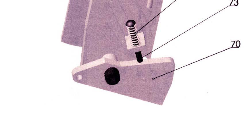
4 DEFINITION This lift is a 9000 lb. capacity, 2-Post Lift with a latch system. The safety latch is in contact with the latch rack as the lift ascends and drops into place. The safety latch engages in rack at 3 increments beginning about 16 from the ground. The latch must be manually disengaged for the lift to descend. The latch is released by raising the latch up off the latch rack and pulling the release cable. Once the raise button is pressed, the latch will automatically re-engage after approximately 3 of travel. Heavy bearings and heavy-duty leaf chains are used throughout the lift. The work is done with the heavy-duty chain connected to a 2 1/2 cylinder, driven by a hydraulic pump capable of providing 3,000psi. Please read the Safety Procedures and Operation Instructions in this manual before operating and installing the lift. Proper installation is very important. To minimize the chance of making an error in installation, please read this manual through carefully before beginning installation. Check with building owner and/or an engineer when applicable. The lift should be located on a relatively level floor 4 thick and 3,000psi concrete sufficiently cured. This is a vehicle lift installation/operation manual and no attempt is made or implied herein to instruct the user in lifting methods particular to an individual application. Rather, the contents of this manual are intended as a basis for operation and maintenance of the unit as it stands alone or as it is intended and anticipated to be used in conjunction with other equipment. Proper application of the equipment described herein is limited to the parameters detailed in the specifications and the uses set forth in the descriptive passages.
5 PREPARATION The installation of this lift is relatively simple and can be accomplished by 2 people in a few hours. The following tools and equipment are needed: 12 quarts of Non-Detergent Hydraulic Oil SAE-10 AW 32 or other good grade Chalk line and 12 Tape measure Rotary Hammer Drill with 3/4 Drill Bit. Core Drill ReBar Cutter recommended 4 Level Sockets and Open Wrench set, 1/2 thru 1-1/2 (1-1/8 for 3/4 Anchors) Vise Grips GENERAL INFORMATION 1. Identify the components and check for shortages. If shortages are discovered, contact us immediately. Save the shipping bolts for use in the installation. 2. Lift location-check with building owner and /or an engineer when applicable. The lift should be located on a relatively level floor 4 thick and 3,000psi concrete sufficiently cured with no cracks within 38 and no seams with in 6 of the base plate. Remember any structure is only as strong as its foundation. Check for ceiling clearance- lifting height plus vehicle height if installing the Floor Plate Style Lift. Check for clearance in the front and rear of vehicle when on lift. Basic Specification Description Capacity Lifting Time Overall Height Overall Width Between Posts Floor Plate Style/ Asymmetric Overhead Beam Style/ Asymmetric 9000Ibs 50 Sec Ibs 50 Sec Please also read the general information about this lift shown of Figure 1 for Floor Plate Style, Figure 2 for Overhead Beam Style and Figure 3 for Asymmetric type. 5
6 IMPORTANT CONCRETE AND ANCHORING INFORMATION 1. Concrete shall have compression strength of at least 3,000psi and a minimum thickness of 4 in order to achieve a minimum anchor depth of 3 1/2. If the top of the anchor exceeds 2 above the floor grade, you DO NOT have enough depth. 2. Use holes in column base plate as a guide before drilling the 3/4 diameter holes in the concrete floor. Make sure the hole distance from the edge is not less than 6. Hole depth should be a minimum of 4, it is recommended to drive through the 4 concrete, unless you have a high water table. 3. CAUTION: DO NOT install on asphalt or other similar unstable surface. Columns are supported only by anchoring into the floor. 4. Shim each column base until each column is plumb. If one column has to be elevated to match the plane of the other column, then full-size base shim plates should be used (Reference Shim Kit) torque anchors to 130 ft-lbs. Shim thickness MUST NOT exceed 3/8 when using the 5 1/2 long anchor provided with the lift. Adjust the column extensions plumb. 5. If anchors do not tighten to 130 ft-lbs installation torque, then replace concrete under each column base with a 4 X4 X6 thick 3,000psi minimum concrete pad keyed under and flush with the top of existing floor. Let concrete cure before installing lifts and anchors. 6
7 ANCHORING TIP SHEET Anchors must be at least 6 from the edge of the slab or any seam. 1. Use a concrete hammer and a drill, a solid drill bit with a carbide tip, the same diameter as the anchor, 5/8. Do not use excessively worn bits or bits that have been incorrectly sharpened. 2. Keep the drill perpendicular. 3. Let the drill do the work. Do not apply excessive pressure. Lift the drill up and down occasionally to remove residue and reduce binding. 4. Drill the hole to depth equal to length of anchor. 5. For better holding power, blow dust from the hole. 6. Place a flat washer and hex nut over threaded end of anchor, leaving the nut flush with the top of the bolt. Carefully tap anchor into hole. Do not damage threads. Tap anchor into the concrete until nut and flat washer are against base plate. Do not use an impact wrench to tighten. Tighten the nut with two or three turns on average after the concrete has cured (28-day cure). If the concrete is very hard, only one or two turns may be required. 7
8 INSTALLATION INSTRUCTION FOR FLOOR PLATE STYLE AND OVERHEAD BEAM STYLE 2-COLUMN HYDRAULIC LIFTS PLEASE READ THIS INSTRUCTION BEFORE STARTING TO INSTALL THE LIFT STEP 1: After unloading the lift, place it near the installation location. STEP 2: Remove the shipping bands and packing materials from the unit. STEP 3: Remove the packing brackets and bolts holding the two columns together. Do not discard bolts, they are used in the assembly of the lift. STEP 4: Once the power unit column location is decided, insure that the proper lift placement is observed from walls and obstacles. Also, check the ceiling height for clearance in this location. Note the power unit column can be located on either side. It is helpful to try to locate it on the lift to save steps during operation. STEP 5: Figure 5 Page 19 Assemble the uprights to the columns on model Overhead Beam Style Lift (the Floor Plate Style Lift does not have uprights.). Raise the columns to a vertical position. STEP 6: Position the columns facing each other 134 outside base plates. STEP 7: Figure 4 Page 18 Using a 3/4 concrete drill, drill the anchor holes in the main side column, installing anchors as you go. Use a block of wood or rubber mallet to drive anchor bolts in. Drill to a minimum depth of 4 to insure maximum holding power. Drilling through concrete (recommended) will allow the anchor to be driven thru the bottom if the threads are damaged. STEP 8: Check to make sure side-to-side and front-to-back are level. Use 3/4washers or shim stock, placing shims as close as possible to the hole locations. This will prevent bending the column bottom plates. Tighten the 3/4 anchor bolts to 130 ft-lbs. of torque. STEP 9: Figure 5 Page 19 Using a tape measure, measure from back corner of the base on main side column to the opposites back corner of the offside column to insure legs are square. Using the 8
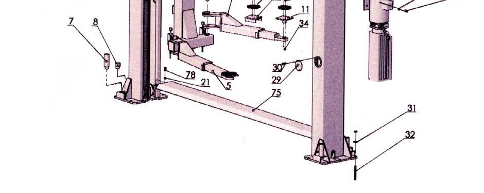
9 dimensions, install overhead beam to top of columns BEFORE drilling anchors for offside column to insure column level. STEP 10: After overhead beam is assembled drill and anchor offside column as described in steps 7 and 8. STEP 11: Figure 6 Page 20 Install the equalizing cables: Refer to figure for general cable arrangement for both Floor Plate Style and Overhead Beam Style Lifts. Set carriages on the first safety latch engagement. Be sure each carriage is at the same height by measuring from the top of the base to the bottom of the carriage. Double check the latches before working under the carriages. This dimension should be with in 1/4 Run first cable as in Figure 6. Tighten nut on one cable stud so that the end of stud passes the nylon on the nut. Pull the other end of cable and run nut on it; tighten both nuts. Repeat above for second cable. STEP 12: Figure 8-9 Pages Install the cylinders: put one cylinder into each carriage by sliding it all the way down through the top of the cylinder mount at column base. Make sure the Tip on the bottom of the cylinder will fit into the center hole on top of the cylinder mount in base. Pull the pre-attached leaf chain in both sides up and over the chain sheave on top of the cylinders. Refer to Figure 8 for Floor Plate Style Lift and Figure 9 for Overhead Beam Style Lift. STEP 13: Figure 8-9 Pages Connecting the hydraulic hoses: as shown on Figure 8 for Floor Plate Style Lift and Figure 9 for Overhead Beam Style Lift. STEP 14: Figure 9 Page 23 Mount the power unit on lift as Figure 9. STEP 15: Installing cut off cable: Take the 2- eye bolts included in the parts box and install them in the holes located in the front of each upright about 6 from the top. Install a nut, and lock washer on either side, to make them secure. Starting on the left side (offside), attach the 1/16 cable to the eye bolt located near the top of the left side upright using the small aluminum ferrules. Loop the cable through the ferrule, then through the eye of the bolt and back through the ferrule. Crimp the ferrule to hold the cable. Pass the cable through the eye bolt on the right side (main side) and down to the power unit. Loop the cable through the eye on the cutoff switch post, located on top of the upswitch junction box, secure with ferrule. Make it as tight as you can without tripping the cutoff switch. 9
10 STEP 16: Figure 4 Page 18 For Floor Plate Style Lift, mount the floor plate as Figure 4. STEP 17: Install the swing arms on the carriages using the included 1 1/2 diameter pins. Check to make sure the rack on the lock should fully engage with the gear on the arm. STEP 18: Adjust the carriage cables tension: adjust each cable to approximately 1/2 side-to side play. Check the latch releases to insure the carriage is still sitting on the appropriate latch. STEP 19: Remove the vent plug from the power unit and fill the reservoir. Use a Ten Weight (SAE-10) non-foaming, non-detergent hydraulic fluid. The unit holds approximately twelve quarts. STEP 20: Make the Electrical hookup to the 220V Single Phase Power Unit. It is recommended that a 220 Volt, 20amp twist lock plug be installed in the power line just ahead of the power unit s size wire for a 20amp circuit. Warning-the wiring must comply with local code. Have a certified electrician make the electrical hook-up to the power unit. Protect each circuit with time delay fuse or circuit breaker 208V-230V single Phrase 60Hz 30amp. Motor cannot run on 50Hz without a physical change to motor. ATTENTION: IF 380V POWER UNIT APPLIES, PLEASE ADJUST AND USE RELATIVE TWIST LOCK AND TIME DELAY FUSE OR CIRCUIT BREAKER ACCORDINGLY! STEP 21: Do not place any vehicle on the lift at this time. Cycle the lift up and down several times to insure latches click together and all air is removed from the system. To lower the lift, both latch releases must be manually released. Latches will automatically reset once the lift ascends approximately 17 from base. If latches click out of sync, tighten the cable on the one that clicks first. RAISE THE LIFT Press button on power unit. The latch mechanism will trip over when the lift raises and drops into each latch stop. But, to lock the lift you must press the Lower level to relieve the hydraulic pressure and let the latch set tight in a lock position. Always lock the lift before going under the vehicle. Never allow anyone to go under the lift when raising or lowering. Read the safety procedures in the manual. Note: It is normal for an empty lift to lower slowly-it may be necessary to add weight. 10
11 LOWER THE LIFT 1. Raise the lift until the latch clears. 2. Pull both latch releases. WARNING ALWAYS RELEASE BOTH SIDES 3. Press the lever at the power unit to lower the lift. SAFETY PROCEDURES Never allow an unauthorized person to operate lift. Thoroughly train new employees in the use and care of the lift. Caution-the power unit operates at high pressure. Remove passengers before raising vehicle. Prohibit unauthorized people from being in shop area while lift is in use. Total lift capacity is 9000lbs with 2500lbs per arm pad. Prior to lifting vehicle, walk around the lift and check for any objects that might interfere with the operation of: lift, safety latches, tools, air hoses or shop equipment. When approaching the lift with a vehicle, center the vehicle between the columns so that the tires will clear the swing arms easily. Slowly drive the vehicle up between the posts. Have someone outside the vehicle guide the driver. Always lift vehicle using all four arms. Never use lift to raise one end or one side of vehicle. Raise vehicles about 3 and check stability by rocking. Prior to lowering vehicle, walk around the lift and check for any objects that might interfere with the operation of lift, safety latches, tools, air hoses or shop equipment. Swing the arms out of the path and slowly drive the vehicle out. Have someone outside the vehicle guide the driver. ALWAYS LOCK THE LIFT BEFORE GOING UNDER THE VEHICLE. NEVER ALLOW ANYONE TO GO UNDER THE LIFT WHEN RAISING OR LOWERING. MAINTENANCE SCHEDULE The following periodic maintenance is the suggested minimum requirements and minimum intervals of accumulated hours or monthly period, which ever comes sooner. If you hear a noise or see any indication of impending failure then cease operation immediately and inspect, correct and/or replace parts as required. 11
12 IT IS IMPORTANT TO INSPECT LIFTING EQUIPMENT AT THE START OF EVERY SHIFT. THESE AND OTHER PERIODIC INSPECTIONS ARE THE RESPONSIBILITY OF THE USER. DAILY PRE-OPERATION CHECK (8 HOURS) The user should perform daily check. ATTENTION! Daily check of safety latch system is very important and the discovery of device failure before needed could save you from expensive property damage, lost production time, serious personal injury or even death. Check safety lock audibly and visually while in operation. Check safety latches for free movement and full engagement with rack. Check hydraulic connections and hoses for leakage. Check chain connections for bends, cracks and looseness. Check cables connections for bends, cracks and looseness. Check for frayed cables in both raised and lowered position. Check snap rings at each roller and sheave. Check bolts, nut and screws. Tighten if needed. Check wiring and switches for damage. Keep base plate free of dirt, grease or any other corrosive substances. Check floor for stress cracks near anchor bolts. Check swing arm restraints. WEEKLY MAINTENANCE (40 HOURS) Check anchor bolts torque to 130 ft-ibs for the 3/4 anchor bolts. Do not use impact wrench. Check floor for stress cracks near anchor bolts. Check hydraulic oil level. Check and tighten bolts, nuts and screws. Check cylinder pulley assembly for free movement or excessive wear on cylinder yoke or pulley pin. Check cable pulley for free movement and excessive wear. YEARLY MAINTENANCE Lubricate chain. Grease rub blocks and column surface contacting rub blocks. Change the hydraulic fluid. Good maintenance procedure makes it mandatory to keep hydraulic fluid clean. Due to operating temperature, type of service, contamination levels, filtration and chemical composition of fluid, the hydraulic fluid may need to be changed more or less frequently. If operating in dusty 12
13 environment shorter interval may be required. The following items should only be performed by a trained maintenance expert. Replace hydraulic hoses. Replace chains and rollers. Replace cables and sheaves. Replace or rebuild air and hydraulic cylinders as required. Replace or rebuild pumps/motors as required. Check hydraulic and air cylinder rod and rod end (threads) for deformation or damage. Check cylinder mount for looseness and damage. Relocating or changing components may cause problems. Each component in the system must be compatible; an undersized or restricted line will cause a drop in pressure. All valve, pump and hose connections should be sealed and/or capped until just prior to use. Air hoses can be used to clean fittings and other components. However, the air supply must be filtered and dry to prevent contamination. NOTE: Contamination is the most frequent cause of malfunction or hydraulic equipment. TROUBLE SHOOTING 1. Motor dose not run: A. Breaker or fuse is blown. B. Motor thermal overload tripped. Wait for overload to cool. C. Faulty wiring connections. Call electrician. D. Defective up button. Call electrician for checking. 2. Motor runs but will not raise: A. A piece of trash is under check valve. Push the handle down and the up button at the same time. Hold for seconds. This should flush the system. B. Check the clearance between the plunger valve of the lowering handle. There should be 1/16clearance. C. Remove the check valve cover and clean ball and seat. D. Oil level should be just under the vent cap port when the lift is down. 3. Oil blows out breather of power unit: A. Oil reservoir overfilled. B. Lift lowered too quickly while under a heavy load. C. Return tube is loose or disconnected. 13
14 4. Motor hums and will not run: A. Impeller fan cover is dented. Take off and straighten. B. Faulty wiring. Call electrician C. Bad capacitor. Call electrician D. Low voltage. Call electrician E. Lift overloaded. Reduce load. 5. Lift jerks going up and down: air in hydraulic system. Raise lift all the way to the top and return to floor. Repeat 4-6 times. Do not let this overheat power unit. 6. Oil leaks: A. Power unit: If the power unit leaks hydraulic oil around the tank mounting flange then check the oil level in the tank. The level should be two inches below the flange of the tank. Check with a screwdriver. B. Rod end of cylinder: If the rod seal of the cylinder is leaking, then rebuild or replace the cylinder. C. Breather end of the cylinder: If the piston seal of the cylinder is leaking, then rebuild or replace the cylinder. 7. Lift makes excessive noise: A. Leg of the lift is dry and requires grease. B. Cylinder pulley assembly or cable pulley assembly is not moving freely. C. Pins or cylinder yoke may have excessive wear. OWNER / EMPLOYER RESPONSIBILITIES The Owner/Employer: Shall establish procedures to periodically maintain, inspect and care for the lift in accordance with the manufactures recommended procedures to ensure continued safe operations. Shall provide necessary lockout / tagouts of energy sources per ANSIZ before beginning any lift repairs. Shall not modify the lift in any manner without prior written consent of the manufacturer. Shall display the operating instructions supplied with the lift in a conspicuous location in the lift area convenient to the operator. Shall ensure that lift operators are instructed in the proper and safe use and operation of the lift using the manufacturer s instructions supplied with the lift. 14
15 INSTALLATION INSTRUCTION Fig 1 For Floor Plate Lift 15
16 INSTALLATION INSTRUCTION Fig 2 For Overhead Lift 16


17 INSTALLATION INSTRUCTION Fig 3 Asymmetric Type 17
18 INSTALLATION INSTRUCTION Fig 4 Prepare Concrete 18
19 INSTALLATION INSTRUCTION Fig 5 Upright, Overhead Beam Assembly 19
20 INSTALLATION INSTRUCTION Fig 6 Equalizing Cable Installation Overhead Beam Type 20
21 INSTALLATION INSTRUCTION Fig 7 Equalizing Cable Installation Floor Plate Type 21
22 INSTALLATION INSTRUCTION Fig 8 Hydraulic System Assembly Floor Plate Type 22
23 INSTALLATION INSTRUCTION Fig 9 Hydraulic System Assembly Overhead Beam Type 23
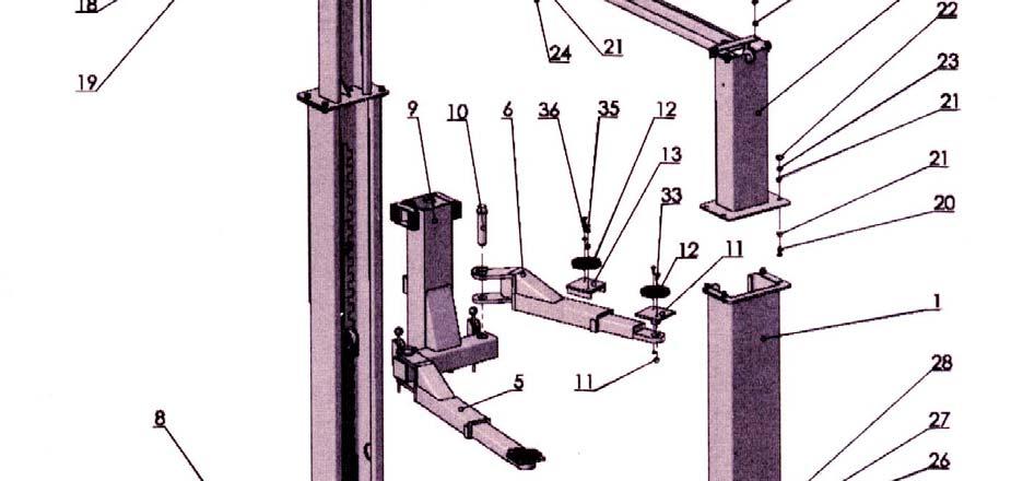
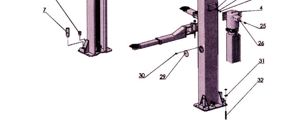
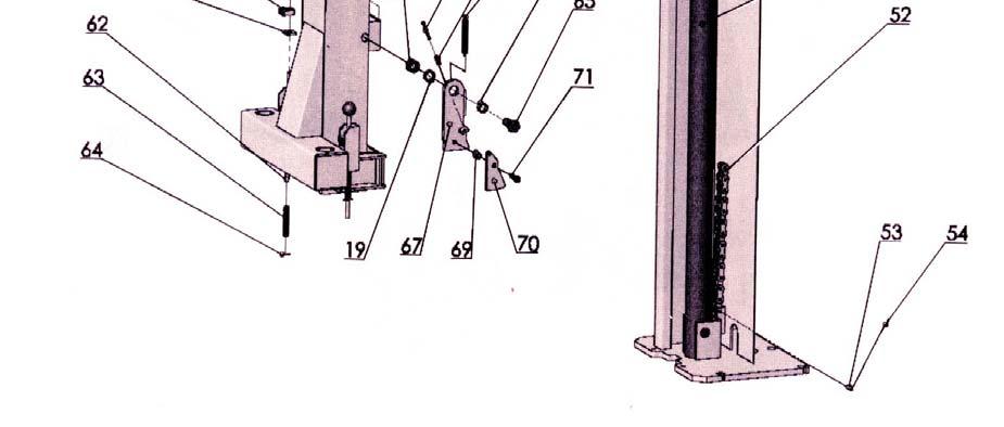
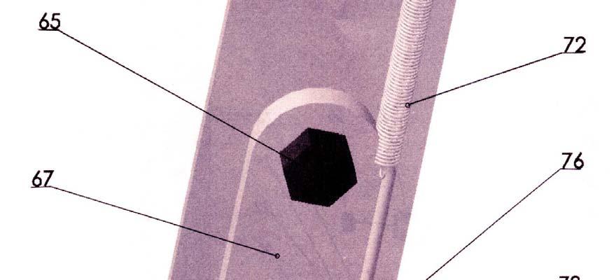
24 24
25 25
26 26

27 27

28 28
29 29
30 30
31 31
32 32
33 33
Model FP12K-K Flat Deck Four-Post Lift
 Model FP12K-K Flat Deck Four-Post Lift (12,000LBS Capacity) ASSEMBLY & OPERATION INSTRUCTION 2006.4. TABLE OF CONTENTS Important Note--------------------------------------------------------------------------------Page
9,000 POUND TWO-COLUMN AUTOMOTIVE LIFT. Model: NW-2-9KACD MANUAL
 9,000 POUND TWO-COLUMN AUTOMOTIVE LIFT Model: NW-2-9KACD MANUAL 1 9,000 POUND CAPACITY MODEL: NW-2-9KACD TWO-COLUMN AUTOMOTIVE LIFT READ THIS ENTIRE MANUAL BEFORE OPERATION BEGINS RECORD BELOW THE FOLLOWING
9,000 POUND TWO-COLUMN AUTOMOTIVE LIFT Model: NW-2-9KFP MANUAL
 9,000 POUND TWO-COLUMN AUTOMOTIVE LIFT Model: NW-2-9KFP MANUAL 1 9,000 POUND CAPACITY MODEL: NW-2-9KFP TWO-COLUMN AUTOMOTIVE LIFT READ THIS ENTIRE MANUAL BEFORE OPERATION BEGINS RECORD BELOW THE FOLLOWING
Model: TPO310-ACX MANUAL
 PEAK-AUTOLIFT 10,000 POUND TWO-COLUMN AUTOMOTIVE LIFT Model: TPO310-ACX MANUAL AutoTool 2739 W 79 th St #16 Hialeah, FL 33016 Phone: (305) 825-9600 www.autotool.net Rev. 2010 Table of Contents WARRANTY...3
TP15KC-KX Two-Post Clear Floor Lift
 TP15KC-KX Two-Post Clear Floor Lift (Symmetric) 15,000 lbs. Capacity (3,750 lbs. Max per Arm) ASSEMBLY & OPERATION INSTRUCTION MANUAL Feb. 2017 IMPORTANT NOTES READ THE INSTALLATION AND OPERATION MANUAL
INSTALLATION & OPERATION MANUAL
 Two-Post Clear Floor Lift (Asymmetric) 9,000 lbs. Capacity (2,250 lbs. Max per Arm) INSTALLATION & OPERATION MANUAL IMPORTANT NOTES READ THE INSTALLATION AND OPERATION MANUAL IN ITS ENTIRETY BEFORE ATTEMPTING
Model FP14KA-C Alignment Four-Post Lift
 Model FP14KA-C Alignment Four-Post Lift (14000 LBS Capacity) ASSEMBLY & OPERATION INSTRUCTION 2006.4. TABLE OF CONTENTS Important Note--------------------------------------------------------------------------------Page
ATD-2P9A 9,000 lbs. Two Post Clear Floor Lift Owner s Manual
 ATD-2P9A 9,000 lbs. Two Post Clear Floor Lift Owner s Manual Features: Specifications: IMPORTANT NOTES READ THE INSTALLATION AND OPERATION MANUAL IN ITS ENTIRETY BEFORE ATTEMPTING TO INSTALL THE LIFT.
IMPORTANT INFORMATION
 TABLE OF CONTENTS IMPORTANT INFORMATION... 2 LIFT AREA LAYOUT INFORMATION... 3 TOOLS and EQUIPMENT REQUIRED FOR INSTALL... 4 INSTALLATION PROCEDURE... 5 FOUNDATION and ANCHORING REQUIREMENTS... 6 DEFINITION
INSTALLATION MANUAL & OPERATION INSTRUCTIONS. OVERHEAD CAR LIFT 2-POST LIFT AUTO HOIST APlusLift HW-10KOH
 INSTALLATION MANUAL & OPERATION INSTRUCTIONS OVERHEAD CAR LIFT 2-POST LIFT AUTO HOIST APlusLift HW-10KOH 1 READ THIS MANUAL COMPLETELY BEFORE INSTALLING LIFT!!! DISTRIBUTED BY: Songa Enterprises LLC 8512
Model FP14KO-A Wheel alignment & Open Front Four-Post Lift
 Model FP14KO-A Wheel alignment & Open Front Four-Post Lift ( 14000LBS / 6300Kg Capacity) ASSEMBLY & OPERATION INSTRUCTIONS ( Series T1) 2009.7. INTRODUCTION Model FP14KO-A is a four-post lift is used in
ATD-4P14CCA 14,000 lb Capacity Closed Front Alignment Lift ASSEMBLY & OPERATION INSTRUCTION MANUAL
 ATD-4P14CCA 14,000 lb Capacity Closed Front Alignment Lift ASSEMBLY & OPERATION INSTRUCTION MANUAL 14,000 LB. FOUR POST CABLE DRIVEN ALIGNMENT LIFT ATD-4P14CCA 14,000 lb. capacity Four post Cable driven
Read this entire manual before operation begins.
 Read this entire manual before operation begins. Record below the following information which is located on the serial number data plate. Serial No. Model No. Date of Installation Contents Important Information........
ATD2P11BS. Two-Post Clear Floor Bi-Symmetric Automotive Lift. Installation & Operation Manual. 11,000 lbs. Capacity. (2,750 lbs.
 Two-Post Clear Floor Bi-Symmetric Automotive Lift 11,000 lbs. Capacity (2,750 lbs. Max per Arm) Installation & Operation Manual 1. Safety Information 1.1 Note, Caution and Warning 1.2 Important Information
ATTENTION. 1. Do not attempt to use the power unit to extend your cylinder. This must be done manually.
 NSS8XLT Installation Manual ATTENTION By following the instructions in this manual you can save yourself much time, frustration and money. The installation of your lift will take 4-5 hours. Do not rush.
INSTALLATION / OWNERS MANUALS
 Floor Plate Automotive Lift 9,000 POUND CAPACITY IMPORTANT Reference ANSI/ALI ALIS, Safety Requirements for Installation and Service of Automotive Lifts before installing lift. INSTALLATION / OWNERS MANUALS
BLAZER 9000 LUBE LIFT OPERATOR AND PARTS MANUAL
 BLAZER 9000 LUBE LIFT OPERATOR AND PARTS MANUAL Blazer 9000 Lube Lift Operator s Manual Note: Instructions must be read thoroughly before installing, operating, or maintaining the lift. Devon Lube Center
CONTENTS. Product Features and Specifications Installation Requirement Installation Exploded View Operation Instruction...
 1 CONTENTS Product Features and Specifications... 3 Installation Requirement... 5 Installation... 6 Exploded View... 20 Test... 22 Operation Instruction... 25 Maintenance... 26 Trouble Shooting... 27 Parts
ATD-4P9DXL. Four Post Lift. 9,000 lbs. Capacity. (4,500 lbs. per axle) INSTALLATION / OWNERS MANUAL
 INSTALLATION / OWNERS MANUAL") ATD-4P9DXL Four Post Lift 9,000 lbs. Capacity (4,500 lbs. per axle) INSTALLATION / OWNERS MANUAL Jan 2017 READ THIS MANUAL THOROUGHLY BEFORE INSTALLING, OPERATING, OR MAINTAINING THIS LIFT. WHEN DONE WITH
ATD-4P9DXL Four Post Lift 9,000 lbs. Capacity (4,500 lbs. per axle) INSTALLATION / OWNERS MANUAL Jan 2017 READ THIS MANUAL THOROUGHLY BEFORE INSTALLING, OPERATING, OR MAINTAINING THIS LIFT. WHEN DONE WITH
Installation Manual. Installation Instructions. Operation. TP15KC Parts Check List Notes about your TP15KC lift
 Installation Manual Parts Check List Notes about your lift Installation Instructions Step 1 Measure lift area and check for defects Step 2 Cylinder assembly Step 3 Position columns and uprights, level
CONTENTS. Product Features and Specifications Installation Requirement Steps of Installation 4. Exploded View Test Run...
 CONTENTS Product Features and Specifications... 1 Installation Requirement... 3 Steps of Installation 4 Exploded View... 14 Test Run... 16 Operation Instruction... 19 Maintenance... 20 Trouble Shooting...
TL4.0OHDI (9KOH) INSTALLATION / OWNERS MANUAL
 INSTALLATION / OWNERS MANUAL") TL4.0OHDI (9KOH) INSTALLATION / OWNERS MANUAL TWO POST HOIST Capacity: 4 TONNE Read this manual thoroughly before installing, operating, or maintaining this lift. When done with installation be sure to
TL4.0OHDI (9KOH) INSTALLATION / OWNERS MANUAL TWO POST HOIST Capacity: 4 TONNE Read this manual thoroughly before installing, operating, or maintaining this lift. When done with installation be sure to
Read this entire manual before operation begins.
 Read this entire manual before operation begins. Record below the following information which is located on the serial number data plate. Serial No. Model No. Date of Installation Contents Specifications.............
Lifting height 5.5" - 72" with adapters " Height overall 165" Width between columns 122" Drive through 109" Width overall 151.
 Model Number TP12KC-D Capacity 12,000 lbs. Lifting height 5.5" - 72" with adapters 79.625" Height overall 165" Width between columns 122" Drive through 109" Width overall 151.125" Arm extension 37.5" -
CONTENTS. Product Features and Specifications...1. Installation Requirement Steps of Installation.. 5. Exploded View Test Run...
 CONTENTS Product Features and Specifications...1 Installation Requirement... 3 Steps of Installation.. 5 Exploded View...18 Test Run...21 Operation Instruction...22 Maintenance... 23 Trouble Shooting...
Atlas PV-9WP Addendum
 Atlas PV-9WP Addendum 9,000 lb. Capacity Two-Post Overhead Lift The Atlas PV-9WP above ground hoist is 6 inches wider than the Atlas PV-9P, giving it an overall width of 141 (11 9 ) and a drive thru width
FOUR-POST LIFT. 14,000 lbs. Capacity
 FOUR-POST LIFT 14,000 lbs. Capacity Note: At the rated capacity of 14,000 lbs. lift was designed for: 101" Minimum wheelbase for models without rolling jacks 124" Minimum wheelbase for models with rolling
Read this entire manual before operation begins.
 Read this entire manual before operation begins. Record below the following information which is located on the serial number data plate. Serial No. Model No. Date of Installation Contents Specifications.............
FP8K-B, FP8K-DX & FP8K-DX-XLT Four Post Storage Lifts
 FP8K-B, FP8K-DX & FP8K-DX-XLT Four Post Storage Lifts 8,000 lbs. Capacity (4,000 lbs. per axle) INSTALLATION / OWNERS MANUAL READ THIS MANUAL THOROUGHLY BEFORE INSTALLING, OPERATING, OR MAINTAINING THIS
Installation Instructions Capacity 10,000 lbs. (100 Series Lift)
") Installation Instructions Capacity 10,000 lbs. (100 Series Lift) IMPORTANT Reference ANSI/ALI ALIS, Safety Requirements for Installation and Service of Automotive Lifts before installing lift. OPERATING
Installation Instructions Capacity 10,000 lbs. (100 Series Lift) IMPORTANT Reference ANSI/ALI ALIS, Safety Requirements for Installation and Service of Automotive Lifts before installing lift. OPERATING
Read this entire manual before operation begins.
 Read this entire manual before operation begins. Record below the following information which is located on the serial number data plate. Serial No. Model No. Date of Installation Contents Specifications.............
TWO POST LIFT INSTALLATION AND OWNERS MANUAL
 TWO POST LIFT INSTALLATION AND OWNERS MANUAL DP15, DP15-2 Capacity 15,000 lbs. 1. TABLE OF CONTENTS 2. Important Information.. 2 3. Section 1 Owner s Manual Safety Instructions... 3 Monthly Maintenance...
WHIP INDUSTRIES, INC.
 WHIP INDUSTRIES, INC. WFP30R, WFP30R-E & WFP30R-EE STD., EXT. & E-EXT. 30,000 LBS CAPACITY FOUR POST ABOVE GROUND LIFT INSTALLATION INSTRUCTIONS & MANUAL WHIP INDUSTRIES, INC 3010 S MAIN ST. FORT WORTH,
TWO POST LIFT INSTALLATION AND OWNERS MANUAL. January 2008 rev. E I MAN
 TWO POST LIFT INSTALLATION AND OWNERS MANUAL DP15, DP15-2 Capacity 15,000 lbs. January 2008 rev. E 1. TABLE OF CONTENTS 2. Important Information.. 2 3. Section 1 Owner s Manual Safety Instructions... 3
Read this entire manual before operation begins.
 Read this entire manual before operation begins. Record below the following information which is located on the serial number data plate. Serial No. Model No. Date of Installation Contents Specifications.............
Read this entire manual before operation begins.
 Read this entire manual before operation begins. Record below the following information which is located on the serial number data plate. Serial No. Model No. Date of Installation Contents Important Information........
CONTENTS. Product Features and Specifications...1. Installation Requirement...3. Steps of Installation...4. Exploded View Test Run...
 TP10AS 2-POST LIFT CONTENTS Product Features and Specifications...1 Installation Requirement...3 Steps of Installation...4 Exploded View...24 Test Run....28 Operation Instruction...29 Maintenance...30
FP8K-B, FP8K-DX & FP8K-DX-XLT Four Post Storage Lifts
 FP8K-B, FP8K-DX & FP8K-DX-XLT Four Post Storage Lifts 8,000 lbs. Capacity (4,000 lbs. per axle) INSTALLATION / OWNERS MANUAL READ THIS MANUAL THOROUGHLY BEFORE INSTALLING, OPERATING, OR MAINTAINING THIS
Models PR-12F PR-12C PR-15C SURFACE MOUNTED TWO-POST LIFTS INSTALLATION AND OPERATION MANUAL
 Forward this manual to all operators. Failure to operate this equipment as directed may cause injury. INSTALLATION AND OPERATION MANUAL SURFACE MOUNTED TWO-POST LIFTS Models PR-12F PR-12C PR-15C Keep this
2-Post Lift Operations and Maintenance Manual
 2-Post Lift Operations and Maintenance Manual Table Of Contents Safety Instructions... 2 Owner/Employer Responsibilities / Operating Conditions... 3 Operating Instructions... 4 Maintenance Instructions...
Index. 1. Important safety instructions Overview of the lift Installation instructions Operation instructions 8-9
 2 Index 1. Important safety instructions 4-5 1.1 Safety Warnings 1.2 Qualified personnel 1.3 Safety 1.4 Warning signs 2. Overview of the lift 6 2.1 General descriptions 2.2 Technical data 2.3 Construction
INSTALLATION MANUAL & OPERATION INSTRUCTIONS
 INSTALLATION MANUAL & OPERATION INSTRUCTIONS 2 POST LIFT PSE 12,000 OHP INSTALLATION Manual PSE 12,000 OHP (Manual Controls With No Key Security Box) Heavy-Duty Symmetric 2 Post Lift 12,000 LB. Capacity
PP8S Four Post Lift 8,000 lbs. Capacity
 PP8S Four Post Lift 8,000 lbs. Capacity (4,000 lbs. per axle) Minimum wheelbase 100" at rated capacity IMPORTANT INSTALLATION / OWNERS MANUAL Read this manual thoroughly before installing, operating, or
SCISSOR LIFT Model MR6K-38 /161108A 6,000lb Capacity Operation Manual
 SCISSOR LIFT Model MR6K-38 /161108A 6,000lb Capacity Operation Manual (Version A) 2009. Apr. CONTENT 1. Safety Note, Caution and Warning Important Information Safety Instructions 2. Technical Manual Product
IMPORTANT INFORMATION
 1 TABLE OF CONTENTS IMPORTANT INFORMATION... pg 2 LIFT SPECIFICATIONS & FLOOR PLAN... pg 3 TOOLS REQUIRED... pg 4 INSTALLATION INSTRUCTIONS... pg 4 CASTER KIT ASSEMBLY / INSTALLATION... pg 6 FOUNDATION
TWO POST LIFT INSTALLATION AND OWNERS MANUAL Capacity 10,000 lbs.
 TWO POST LIFT INSTALLATION AND OWNERS MANUAL Capacity 10,000 lbs. May 2009 All rights reserved. CO7378.2 IN60005 Rev. - 5/7/2009 TABLE OF CONTENTS Important Information...2 Section 1 Owner s Manual Safety
Installation Instructions Capacity 10,000 lbs. DP10 (200 Series Lift)
") Installation Instructions Capacity 10,000 lbs. DP10 (200 Series Lift) IMPORTANT Reference ANSI/ALI ALIS, Safety Requirements for Installation and Service of Automotive Lifts before installing lift. OPERATING
Installation Instructions Capacity 10,000 lbs. DP10 (200 Series Lift) IMPORTANT Reference ANSI/ALI ALIS, Safety Requirements for Installation and Service of Automotive Lifts before installing lift. OPERATING
TP10KACD REV A
 TP10KACD 10, 000l bcapaci t y TwoPostAsymmet r i caut oli f t REV A-061813 Table of contents Important Information Section 1 Owner s Manual Safety Instructions Monthly Maintenance Troubleshooting Section
Read this entire manual before operation begins.
 Read this entire manual before operation begins. Record below the following information which is located on the serial number data plate. Serial No. Model No. Date of Installation Contents Specifications.............
Read this entire manual before operation begins.
 Read this entire manual before operation begins. Record below the following information which is located on the serial number data plate. Serial No. Model No. Date of Installation Contents Important Information........
If facility voltage is different, refer to set-up instructions. IMPORTANT This lift is wired and adjusted to operate at 230 volts.
 MODEL 40/50K Installation And Owner s Manual (000Series) Capacity 40,000 lbs. (20,000 lbs. per axle) Capacity 50,000 lbs. (25,000 lbs. per axle) Four Post Surface Mounted Lift IMPORTANT This lift is wired
Read this entire manual before operation begins.
 Read this entire manual before operation begins. Record below the following information which is located on the serial number data plate. Serial No. Model No. Date of Installation Contents Important Information........
CONTENTS. Product Features and Specifications...1. Installation Requirement Steps of Installation.. 5. Exploded View Test Run...
 CONTENTS Product Features and Specifications...1 Installation Requirement... 4 Steps of Installation.. 5 Exploded View...21 Test Run...26 Operation Instruction...27 Maintenance... 28 Trouble Shooting...
TWO POST LIFT INSTALLATION AND OWNERS MANUAL Capacity 10,000 lbs.
 TWO POST LIFT INSTALLATION AND OWNERS MANUAL Capacity 10,000 lbs. October 2012 by Vehicle Service Group All rights reserved. CO8347 IN60009 Rev. H 10/18/2012 TABLE OF CONTENTS Important Information...2
EE 6435S, 6435A, 6435B Electrical Release FOUR POST LIFT with PD
 EE 6435S, 6435A, 6435B Electrical Release FOUR POST LIFT with PD ATTENTION: READ THIS ENTIRE MANUAL BEFORE INSTALLATION TO ENSURE A CORRECT OPERATION AND LONG SERVICE LIFE. INSTALLATION/OWNERS MANUAL Read
INSTALLATION, OPERATION & MAINTENANCE MANUAL
 INSTALLATION, OPERATION & MAINTENANCE MANUAL MODEL: HD2P-10000AC-D 10,000 LB CAPACITY 2 POST DIRECT DRIVE LIFT FOLLOW THIS MANUAL CAREFULLY TO ENSURE THE EQUIPMENT WILL FUNCTION CORRECTLY AND PROVIDE MANY
Make sure you have extra help or heavy duty lifting equipment when unloading and assembling the Atlas Auto SPINS Rotisserie.
 IMPORTANT INFORMATION Any freight damage must be noted on the freight bill before signing. Identify the components and check for shortages. If shortages are discovered, please contact Greg Smith Equipment
Installation, operation and maintenance manual
 Installation, operation and maintenance manual HCT1LX30 FULL RISE SCISSOR LIFT READ THIS ENTIRE MANUAL BEFORE INSTALLATION TO ENSURE CORRECT OPERATION AND A LONG SERVICE LIFE 2 Tiraines str. Riga, LV 1058
1300 lb Capacity Trike Lift
 M-1300C-TRIKE 1300 lb Capacity Trike Lift USER S MANUAL TRIKE MOTORCYCLE LIFT An extra wide platform designed especially for three-wheel motorcycles. M-1300-TRIKE Trike Motorcycle Lift SPECIFICATIONS:
Model SL-12K-A SCISSOR LIFT. wheel alignment model. (11000 LBS / 5000Kg Capacity) INSTALLATION & OPERATION INSTRUCTION (SECOND EDITION)
 INSTALLATION & OPERATION INSTRUCTION (SECOND EDITION)") Model SL-12K-A SCISSOR LIFT wheel alignment model (11000 LBS / 5000Kg Capacity) INSTALLATION & OPERATION INSTRUCTION (SECOND EDITION) 2007. 6. CONTENTS Chapter 1 Introduction & Specifications ---------------------------------------
Model SL-12K-A SCISSOR LIFT wheel alignment model (11000 LBS / 5000Kg Capacity) INSTALLATION & OPERATION INSTRUCTION (SECOND EDITION) 2007. 6. CONTENTS Chapter 1 Introduction & Specifications ---------------------------------------
Lincoln Hoist. Web Hoist Operating Manual. Lincoln Hoist
 Lincoln Hoist Web Hoist Operating Manual Lincoln Hoist Mfg. by Lincoln Precision Machining Company 121 Creeper Hill Road, P.O. Box 458, North Grafton, MA 01536 USA Toll Free (888) 306-7222 Phone (774)
OPERATION AND PARTS MANUAL
 OPERATION AND PARTS MANUAL MODEL NUMBER : PART NUMBER : GTL 1110 1900-0510 SERIAL NUMBER : BAYNE MACHINE WORKS, INC. PHONE: (864) 288-3877 910 FORK SHOALS ROAD TOLL FREE: (800) 535-2671 GREENVILLE S.C.,
ASSEMBLY & OPERATION INSTRUCTION MANUAL
 LR-26-PAD 6000 lb Capacity Low-Rise Pad Lift ASSEMBLY & OPERATION INSTRUCTION MANUAL 6,000 LB. LOW-RISE PAD LIFT Easy frame lifting on padded runways. Great for wheel and brake work, tire and wheel changing
T R I N S I N S U C N S
 R O TA R Y V A L I D A T E D CERTIFIED B Y E L T SPOA7, SPOA9, SPO9 Two Post Surface Mounted Lift (200 Series Lifts) SPOA7 Capacity 7,000lbs. SPOA9 Capacity 9,000lbs. 1750 lbs. per arm 2250 lbs. per arm
Kysor On/Off Rear Air Fan Drive
 . Proper precautions must be taken to prevent personal injury from contact with moving parts, unintended engine start, or other hazards present when working with powered equipment. Refer to the vehicle
It is the shop owner's responsibility to train all operators in lift operation and safety.
 2 Your new lift will provide years of dependable service if installed, operated and maintained properly. Read and be prepared to follow all safety, installation, operation, and maintenance instructions
Installation Instructions
 Preparing your vehicle to install your brake system upgrade 1. Rack the vehicle. 2. If you don t have a rack, then you must take extra safety precautions. 3. Choose a firmly packed and level ground to
TP12KC-DX. Two Post Clear Floor. Automotive Lift. 12,000 lb. Capacity. (3,000 lbs. Max Capacity per Arm) Installation & Operation Manual
 Installation & Operation Manual") Two Post Clear Floor Automotive Lift 12,000 lb. Capacity (3,000 lbs. Max Capacity per Arm) Installation & Operation Manual IMPORTANT!! READ MANUAL THOROUGHLY BEFORE INSTALLING, OPERATING, SERVICING OR
Two Post Clear Floor Automotive Lift 12,000 lb. Capacity (3,000 lbs. Max Capacity per Arm) Installation & Operation Manual IMPORTANT!! READ MANUAL THOROUGHLY BEFORE INSTALLING, OPERATING, SERVICING OR
JEEVES. JEEVES Installation Manual. Installation Manual The Easiest Do-It-Yourself Dumbwaiter on the Market
 1 888-323-8755 www.nwlifts.com JEEVES Installation Manual The Easiest Do-It-Yourself Dumbwaiter on the Market This manual will cover the installation procedure step-by-step. The installation of this dumbwaiter
STACKER INSTRUCTION MANUAL
 STACKER INSTRUCTION MANUAL The Mobile Stackers are lifting devices featuring easy, flexible, reliable and safe operation suitable for transportation of loads in such applications as warehouses, manufacturing
Read this entire manual before operation begins.
 Rev. 12/12/2017 Read this entire manual before operation begins. Record below the following information which is located on the serial number data plate. Serial No. Model No. Date of Installation Contents
QJY245DS~DA. Two Post Lift Installation & Adjustment Manual
 QJY245DS~DA Two Post Lift Installation & Adjustment Manual Table of Contents 1. Warning 2 2. Summary 2 3. Use 2 4. Mainly technology parameter 2 5. Basic structure of the production 3 6. Safety device
MSC-6KLP Low Profile Mobile Single Column Lift. 6,000 lb. Capacity (1,500 lbs. Max Capacity per Arm) Installation & Operation Manual
 Installation & Operation Manual") Low Profile Mobile Single Column Lift 6,000 lb. Capacity (1,500 lbs. Max Capacity per Arm) Installation & Operation Manual INDEX PREFACE-------------------------------------------------------------------------------
Low Profile Mobile Single Column Lift 6,000 lb. Capacity (1,500 lbs. Max Capacity per Arm) Installation & Operation Manual INDEX PREFACE-------------------------------------------------------------------------------
Kysor On/Off Rear Air Fan Drive
 . Proper precautions must be taken to prevent personal injury from contact with moving parts, unintended engine start or other hazards present when working with powered equipment. Refer to the vehicle
INSTALLATION, OPERATION, & MAINTENANCE MANUAL
 INSTALLATION, OPERATION, & MAINTENANCE MANUAL MODEL: HD2P-10000C-D 10,000 LB CAPACITY 2 POST DIRECT DRIVE LIFT FOLLOW THIS MANUAL CAREFULLY TO ENSURE THE MACHINE WILL FUNCTION CORRECTLY AND PROVIDE MANY
ASSEMBLY & OPERATION INSTRUCTION MANUAL
 Sliding Bridge Jack 3,500 lbs. Capacity ASSEMBLY & OPERATION INSTRUCTION MANUAL TABLE OF CONTENTS Specifications... 2 Description & Features... 3 Installation Instructions... 4 Safety Instructions... 4
Read this entire manual before operation begins.
 Read this entire manual before operation begins. Record below the following information which is located on the serial number data plate. Serial No. Model No. Date of Installation Contents Specifications.............
Read this entire manual before operation begins.
 Revised 9/5/2018 Read this entire manual before operation begins. Record below the following information which is located on the serial number data plate. Serial No. Model No. Date of Installation Contents
SERVICE INSTRUCTIONS D TON
 1120 SOUTH CRYSTAL AVE * BENTON HARBOR MI PH: 269-925-7777 FAX: 269-925-6656 SERVICE INSTRUCTIONS D-51223 4 TON TO ASSEMBLE: 1. Check the handle set screw for tightness. CUSTOMER PRE-USE INSTRUCTIONS THE
INSTALLATION, OPERATION & MAINTENANCE MANUAL
 INSTALLATION, OPERATION & MAINTENANCE MANUAL Two Post Surface Mounted Lift MODEL X10 10,000 LBS. CAPACITY 2500 LBS. PER ARM 200 Cabel Street, P.O. Box 3944 Louisville, Kentucky 40201-3944 Email:sales@challengerlifts.com
Kysor Rear Air Fan Drives
 On/Off Technology for Heavy-Duty Truck Applications Installation & Service Guide Kysor Rear Air Fan Drives thermal.borgwarner.com For Additional BorgWarner Thermal Systems Information: 800-927-7811 USA
PP8 Plus Long Four Post Lift 8,000 lbs. Capacity
 PP8 Plus Long Four Post Lift 8,000 lbs. Capacity (4,000 lbs. per axle) Minimum wheelbase 115 at rated capacity IMPORTANT Reference ANSI/ALI ALIS, Safety Requirements for Installation and Service of Automotive
Chrysler TorqueFlite Shift Improver Kit Part No A-727 (V-8) A-904 (V-8) (A-998 & A-999)
 A-904 (V-8) (A-998 & A-999)") FORM # 9500606-03 Installation Instructions Chrysler TorqueFlite Shift Improver Kit Part No. 10225 1971-1977 A-727 (V-8) 1971-1977 A-904 (V-8) (A-998 & A-999) 1998, 2005, 2010 by B&M Racing & Performance
FORM # 9500606-03 Installation Instructions Chrysler TorqueFlite Shift Improver Kit Part No. 10225 1971-1977 A-727 (V-8) 1971-1977 A-904 (V-8) (A-998 & A-999) 1998, 2005, 2010 by B&M Racing & Performance
OPERATION AND PARTS MANUAL
 OPERATION AND PARTS MANUAL MODEL NUMBER : PART NUMBER : GRL 1110 1900-0540 SERIAL NUMBER : BAYNE MACHINE WORKS, INC. PHONE: 864.288.3877 910 FORK SHOALS ROAD TOLL FREE: 800.535.2671 GREENVILLE SC, 29605
SPO15, SPO18 I N S T A L L A T I O N I N S T R U C T I O N S
 SPO15, SPO18 Sprinter SPO15 (3A0 Lifts) Capacity 11,000 lbs. Standard SPO15 (300 Series Lifts) Capacity 15,000 lbs. Standard SPO18 (300 Series Lifts) Capacity 18,000 lbs. SPO15 (31A0 Lifts) Capacity 14,300
Installation Instructions X-Force UTV Lift (000 Series) Capacity 2,275 lbs (1,035 kg)
 Capacity 2,275 lbs (1,035 kg)") Installation Instructions X-Force UTV Lift (000 Series) Capacity 2,275 lbs (1,035 kg) Read entire manual before assembling, installing, operating, or servicing this equipment. LP20640 IN20793 September
Installation Instructions X-Force UTV Lift (000 Series) Capacity 2,275 lbs (1,035 kg) Read entire manual before assembling, installing, operating, or servicing this equipment. LP20640 IN20793 September
Operating Instructions & Parts Manual
 Operating Instructions & Parts Manual Grainger Model No. 36NE14 Bucher Hydraulics Model No. M-4509-0217 Please read the instructions carefully and always operate this equipment in a safe manner. Unit Description:
INSTALLATION, OPERATION & MAINTENANCE MANUAL MODELS: HD2P-9KCL 9,000 LB CAPACITY 2 POST LIFT
 INSTALLATION, OPERATION & MAINTENANCE MANUAL MODELS: HD2P-9KCL 9,000 LB CAPACITY 2 POST LIFT FOLLOW THIS MANUAL CAREFULLY TO ENSURE THE MACHINE WILL FUNCTION CORRECTLY AND PROVIDE MANY YEARS OF DEPENDABLE
READ THIS MANUAL BEFORE INSTALLATION AND/OR OPERATION! WARNING:
 1 READ THIS MANUAL BEFORE INSTALLATION AND/OR OPERATION! This is a vehicle lift operation manual and no attempt is made or implied herein to instruct the user in lifting methods particular to an individual
MR6K-48X. Mid-Rise Scissor Lift ASSEMBLY & OPERATION INSTRUCTION MANUAL. 6,000 lbs.
 MR6K-48X Mid-Rise Scissor Lift 6,000 lbs. ASSEMBLY & OPERATION INSTRUCTION MANUAL November 2014 Important! Be sure to read the operating instructions before operating your lift! Getting Ready Make sure
Routine Compressor Maintenance
 Establishing a regular, well-organized maintenance program and strictly following it is critical to maintaining the performance of a compressed air system. One person should be given the responsibility
Installation Instructions
 Installation Instructions 2-Post Capacity 12,000 lbs. OPERATING CONDITIONS Lift is not intended for outdoor use and has an operating ambient temperature range of 41-104 F (5-40 C) IMPORTANT Reference ANSI/ALI
Table of Contents WARN INDUSTRIES PAGE A1
 INSTALLATION INSTRUCTIONS AND OPERATORS GUIDE ProVantage Bucket Conversion Kit Part Number: 84133 (50 ), 83133 (54 ) and 85133 (60 ) Application: Front Mount Plow* * Not recommended for use with Center
CAB TILT HYDRAULIC SYSTEM
 OPERATION, MAINTENANCE and SERVICE INSTRUCTIONS CAB TILT HYDRAULIC SYSTEM WITH POWER-PACKER PUMP, CYLINDERS and LATCHES A division of Actuant Corporation 1-800-745-4142 1 www.powerpackerus.com Notice The
Operating instructions Form no safety definitions
 Operating instructions Form no. 1000437 safety definitions safety symbols are used to identify any action or lack of action that can cause personal injury. Your reading and understanding of these safety
MS2200, MS2500, and MS3000 Suspension Installation Manual ON/OFF HIGHWAY SUSPENSION SYSTEM
 MS22, MS25, and MS3 Suspension Installation Manual ON/OFF HIGHWAY SUSPENSION SYSTEM 972.547.62 8.445.736 FAX: 972.542.97 725 E. UNIVERSITY ST. McKINNEY, TEXAS 7569 www.watsonsuspensions.com Watson & Chalin
INSTALLATION, OPERATION & MAINTENANCE MANUAL MODELS: HD2P-9KFP 9,000 LB CAPACITY 2 POST LIFT
 INSTALLATION, OPERATION & MAINTENANCE MANUAL MODELS: HD2P-9KFP 9,000 LB CAPACITY 2 POST LIFT FOLLOW THIS MANUAL CAREFULLY TO ENSURE THE MACHINE WILL FUNCTION CORRECTLY AND PROVIDE MANY YEARS OF DEPENDABLE
The Da-Lite Difference.
 The Da-Lite Difference. Instruction Book for Boardroom Electrol DA-LITE SCREEN COMPANY, INC. 3100 North Detroit Street Post Office Box 137 Warsaw, Indiana 46581-0137 Phone: 574-267-8101 800-622-3737 Fax:
& Operation Instructions
 Installation Manual & Operation Instructions 4 Post Lift* PSE 10,000 CSP XLT INSTALLATION Manual PSE 10,000 CSP XLT (Portable 4 Post Lift) Heavy-Duty 4 Post Lift 10,000 LB. Capacity Lift Features: 4 Oil
GLO-8000 SERIES (GLO-8000 & GLO-8000XLT)
") GLO-8000 SERIES (GLO-8000 & GLO-8000XLT) 8,000 LBS. CAPACITY FOUR-POST STORAGE LIFT INSTALLATION & OPERATION MANUAL SERIAL NUMBER: INSTALLATION DATE: EAGLE EQUIPMENT 1-800-336-2776 REV2011 03.0 BD SHIPPING
GLO-8000 SERIES (GLO-8000 & GLO-8000XLT) 8,000 LBS. CAPACITY FOUR-POST STORAGE LIFT INSTALLATION & OPERATION MANUAL SERIAL NUMBER: INSTALLATION DATE: EAGLE EQUIPMENT 1-800-336-2776 REV2011 03.0 BD SHIPPING