BLAZER 9000 LUBE LIFT OPERATOR AND PARTS MANUAL
|
|
|
- Imogen Townsend
- 6 years ago
- Views:
Transcription


1 BLAZER 9000 LUBE LIFT OPERATOR AND PARTS MANUAL Blazer 9000 Lube Lift Operator s Manual Note: Instructions must be read thoroughly before installing, operating, or maintaining the lift. Devon Lube Center Equipment Fax:
2 Safety Instructions 1. Always work on the vehicle with the lift on the safety locks. 2. Never allow unauthorized or non-trained personnel to operate lift. Thoroughly train new employees in the use, care and safe operation of the lift. 3. Always lift the vehicle with four points of contact using either the lift frame, rubber pads or lifting arm pads. Ensure that the four points of contact will not shift during operation. 4. Never use the lift to raise only one end or one side of the vehicle. 5. Always keep hands and feet clear of the lift when raising or lowering. 6. Keep area clean of tools, debris, grease and oil. Keep water from gathering on lift base. 7. Passengers should not be allowed inside the vehicle when in operation. Prohibit non-authorized personnel from being in service area while in use. 8. Capacity of the Blazer 9000 is 9000 lbs. Do not exceed the 9000 lb. capacity. Placing a Vehicle on the Blazer 9000 Note: It is critical that the operator positions the lift points per the vehicle manufacturers recommended lift points. Some vehicle manufacturers have identified the proper lift points with triangular markings on the undercarriage of the vehicle or have placed a label inside the front right door. If neither of these are present, refer to the Lifting It Right Guides published by ALI or the Vehicle Lifting Points for Frame Engaged Lifts, ALK/LP Guide. 1. The lift must be completely lowered before bringing the car over the lift. Install the rubber pads or the lifting arms as required after the vehicle is centered over the lift and the vehicle lifting points have been identified. 2. The lifting arms have extra height adapters that can be used depending on how high the vehicle lifting point is from the top of the standard size lifting pad. The height adapters are 2-5/8 and 5 and can be inserted into the adapter holes in the swing arms. Once the desired height is determined, the standard lifting pad is set on the top height adapter. 3. To raise lift, press the green raise button on the power unit. When you get to the desired height, lower until it rests on the safety lock by pressing the red lower button on the power unit. When you are ready to lower the lift, raise the lift off of the safety locks and press the air release button releasing the safeties. While holding down on the air release button, press the red lower button on the power unit. Swing arms out from under the vehicle and place them out of the way. 4. Be sure that the vehicle is stable on the lift and neither front nor rear heavy. With some vehicles, the removal (or installation) of components may cause a critical shift in the balance and result in vehicle instability. Refer to the vehicle manufacturer s service manual for recommended procedures when performing these services. 5. Be sure that arm pads and any adapters used are in secure contact with frame at vehicle manufacturer s recommended lift points. 2
 - CAUTION, WHEN AREM IS EXTENDED BEYOND THIS LINE TOTAL LIFT CAPACITY IS REDUCED TO 4,600 POUNDS. (B) - WARNING, NEVER EXTEND ARM BEYHOND THE STOPS. II. Installation Instructions 1.")
3 WARNINGS: When using Lifting Arms, Arms must not be rotated beyond the line decal on the top plate as shown. The Arm Extensions must not be extended beyond the arm stops as shown. (A) - CAUTION, WHEN AREM IS EXTENDED BEYOND THIS LINE TOTAL LIFT CAPACITY IS REDUCED TO 4,600 POUNDS. (B) - WARNING, NEVER EXTEND ARM BEYHOND THE STOPS. II. Installation Instructions 1. The maximum pit width for the Blazer 9000 is The Blazer 9000 may be mounted on several types of surfaces including regular concrete, pre-cast concrete and other configurations that may utilize metal beams, etc. 3. There should be adequate space on all sides of the lift. Note that the lift and vehicle will move approximately 14 backward as the lift rises to its full height. 4. The bases must be aligned perfectly and the same distance apart. 5. Shim as required to level both sides of the lift. 6. The Blazer 9000 can be surface mounted or recessed mounted. Optional ramps are required if the unit is to be surface installed. 7. See layout dimensions later in this manual. 3
4 4 Layout Dimensions
5 5 Layout Dimensions
6 6
7 Regular Concrete Installation 1. Concrete must be level and uniform and have a thickness of 4 with a rating of 3000PSI. The concrete should be reinforced with wire and rebar. 2. When installing the Blazer 9000 on a concrete floor that has a basement, you should check with the building architect or manufacturer to determine the proper support for the lift. 3. Utilize 5/8 anchor bolts when anchoring in regular concrete floors per the above specifications. Pre-Cast Concrete Installation 1. Pre-cast concrete requires a different anchoring system. Consult with the manufacturer or call for more information before anchoring the lift on a pre-cast concrete system. 2. Never use regular 5/8 anchor bolts on a pre-cast floor. Other Floor Materials 1. When installing the Blazer 9000 on floor materials other than those mentioned above, consult with the manufacturer for best type of anchoring system. Electrical Connection and Power Unit Installation 1. The power unit will normally be mounted on the optional power unit stand that also includes the air valve mounting. Other type mountings, such as pole or wall mounting are possible, but may require special adapters for the motor mount. The unit owner or manager should approve the location. 2. If used, the power unit stand will require (four) 3/8 anchor bolts which are provided with the stand Volt Electrical Operation: The power unit comes wired and ready to plug into a 230-volt, single phase, 60 Hz circuit. Use dedicated, single phase, 25-AMP breaker with time delay fuse or circuit breaker. Wiring must comply with local electrical codes. Hydraulic Connections 1. Reference the hydraulic diagram for instructions on connecting the hydraulic hose on the Blazer The lift comes standard with small connector hoses that can be used with any length hose depending on how far the power unit is mounted from the lift. The standard length hydraulic hose supplied with the unit is 26' and 14'. Additional hose lengths can be purchased as required. The hose length does not have to be the same as long as the air is properly bled from the system during installation. See page 13 for further instructions. 2. The power unit operates at high pressure and adequate care must be taken to make sure all hose fittings are securely tightened. Severe leaking will occur if the hose fittings are not properly tightened. 3. The power unit requires 7-1/2-8 quarts of Dexron III Automatic Transmission Fluid or an equivalent. 4. Make sure breather cap is functional and not broken. 7
8 Air Connections 1. The Blazer 9000 has air safety releases, which require that an air system be installed. 2. The air valve can be mounted on the optional power unit stand referenced above. 3. Maximum air pressure on the system is PSI. Use regulator to control pressure and water filter to keep system dry. 4. Reference page #11 for the air schematic and required connections. Surface Mounting 1. Lifts that cannot be recessed must utilize the optional ramps that will be anchored to the concrete floor. Each ramp is anchored utilizing two 5/8 anchor bolts. The ramp is butted against the lift base, which provides the means for the vehicle to roll on the lift. II. Owner/Employer Responsibilities The owner/employer shall: 1. Ensure that lift operators are instructed in the safe use and operation of the lift using the manufacturer instructions and safety tips. Display a copy of the manual in a location convenient to the lift so the operators can refer to it as required. 2. Establish procedures to maintain, inspect and care for the lift in accordance with the manufacturers recommended procedures to ensure its continued safe operation. 3. Provide necessary lock out/tagouts of energy sources per ANSI Z before beginning any lift repairs. 4. Not modify the lift in any manner without prior written consent of the manufacturer. 5. Ensure that there is adequate drainage around the lift so water will not accumulate on the base of the lift. 6. In the unlikely event that one side of the lift will not lower all the way to the floor, slowly crack the hydraulic line (at the power unit) on the line coming from that side of the lift and allow oil to escape until it reaches he floor. 8
9 AIR BLEEDING PROCEDURE FOR BLAZER 9000 Step #1 Fill the power unit reservoir with Dexron III Mercon Automatic Transmission Fluid or equivalent, approximately 7.5 quarts to start with, check all connections for proper security and clearances around and under both of the lifting surfaces, example,. binding, chafing, and pinching. Warning: Safety eye wear is required prior to equipment operation. Step #2 Prior to connecting the hydraulic hoses to the cylinders, press and hold the green lifting button on the power unit, this will flow fluid through the hydraulic lines/hoses, flushing any foreign material along with any air from the system and allow you to inspect for possible leaks. Cycle the pump until clear fluid is coming out of both lift pad hydraulic hoses + approximately 1 quart. Note: Do not reuse this fluid it is likely contaminated. Step #3 You will need to manually raise or lower each lifting pad to the first or lowest safety lock setting, making sure that it is securely latched into the latch bar on the base plate. Warning: Place a safety block or other material under each lifting surface prior to making these connections. This will allow the installation of the hydraulic hose to the bottom of each hydraulic cylinder. Note: The 90 degree connection to the lift cylinder needs to be secured at such an angle that the hose comes close to the base plate with minimal contact of the base plate. Step #4 Press and hold the green lifting button until both pads are elevated enough to clear the first set of locks, then release. Note: It is common for the pads to raise and lower at different elevations on the initial start up, they will even out as this process unfolds. Depress and hold the air lock release button, this should raise the locks out of the latch bar on both left & right side base plates, simultaneously depressing the red lowering button, the pads should begin to lower within a few moments. Allow the pads to lower all the way to bottom. Duplicate this process numerous times, 5 to 6 cycles, increasing the lifting height by one extra lock per cycle. Each completed operation should facilitate a more even pad elevation and smoother equipment function. Some installations may require more or less cycles to accomplish this stage of the bleeding process. Note: After completing this process, fill the reservoir to the proper fluid level. Note: Do not raise the lift pads to their highest point until completing the entire bleeding process. Step #5. Once you have both lifting services raising/lowering evenly and smoothly you now are ready to put a load on the system to complete the bleeding process. As in Step #1 an inspection around and under each lifting surface for possible leaks and clearances is required. A mid-size vehicle of approximately lbs will be needed to finish this process. Warning: All unnecessary personnel need to be removed from the test area for safety. Stage the vehicle for lifting, utilizing necessary adapters as required, announce the lift operation, and then when all is clear depress the green lifting button. Raise the vehicle until the tires are clear of the floor surface, at this point you will release the green button and depress the lock release button, Warning: As in previous steps make sure before depressing the red down button visually inspect that the locks on both pads are clear of the latch bar on the base plate. Now you can depress the red down button allowing the vehicle to lower down. Make sure that for each cycle you allow the pads to bottom out before starting up again. Continue this process for a few cycles until the vehicle is coming up and going down level/smooth. Note: Do not adjust any valves on the power unit pump without prior contact and instructions to do so from
10 MAINTENANCE DAILY 1. Keep all movement points clean, dry and lightly lubricated. 2. Always keep bolts tight. 3. Check for oil leaks. 4. Keep air regulator maximum PSI. 5. Remove any accumulated moisture from air line filter. 6. Raise lift pads at day s end and remove any standing water or moisture. 7. Use air blow gun to keep moving parts clean & dry. MONTHLY 1. Wipe clean & lightly oil movement parts & lift pad stacking extensions. 2. Re-Torque the anchor bolts if necessary. (See CAUTION Below) 3. Check all connectors, bolts & pins to insure proper mounting & alignment. 4. Make a visual inspection of hydraulic hoses & lines for possible wear or interference. 5. Check fluid level of power unit (use Dexron III or equivalent). CAUTION! ALL ANCHOR BOLTS SHOULD ALWAYS BE TIGHT. Check the bolts periodically and tighten if necessary to ft. lbs. If any of the bolts do not function for any reason, the lift should be shut down until the bolt has been replaced. 10
11 TROUBLESHOOTING THE LIFT 1. Motor does not run: A. Breaker or fuse blown. B. Motor thermal overload tripped. C. Defective UP switch. Replace D. Faulty wiring connections. Call electrician Motor runs but lift will not raise: A. Trash is under the release valve. Push Down button and push Up button at the same time. Hold for 15 seconds. B. Oil level low. Oil level should be just under the fill cap port when the lift is down. 3. Motor runs but lift picks up partial load only: A. Faulty relief valve. Replace. B. Oil is coming out of breather on cylinder. C. Seals damaged. 4. Oil blows out of breather: A. Oil reservoir overfilled. 5. Motor hums and will not run: A. Impeller fan cover is dented in. Take off and straighten. B. Faulty wiring-call electrician. C. Bad capacitor-call electrician. D. Low voltage-call electrician. E. Lift overloaded. 6. Lift jerks up and down: A. Air in system - bleed the system. (See installation instructions bleeding the system). 11
12 WARRANTY REGISTRATION Model No. Date Purchased: Serial No. Invoice No. Name of Purchaser: Mailing Address: Physical Address of Lift: City: State: Zip: Telephone No. Name of Seller: City: State: Zip: Telephone No. Return to: DEVON LUBE CENTER EQUIPMENT P. O. Box OKLAHOMA CITY, OK
13 DEVON LUBE CENTER EQUIPMENT PARTS MANUAL BLAZER
14 14
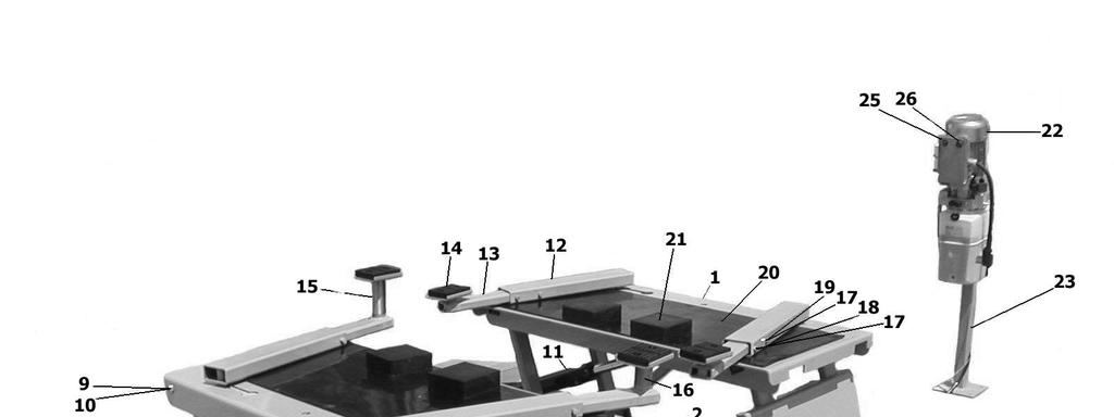
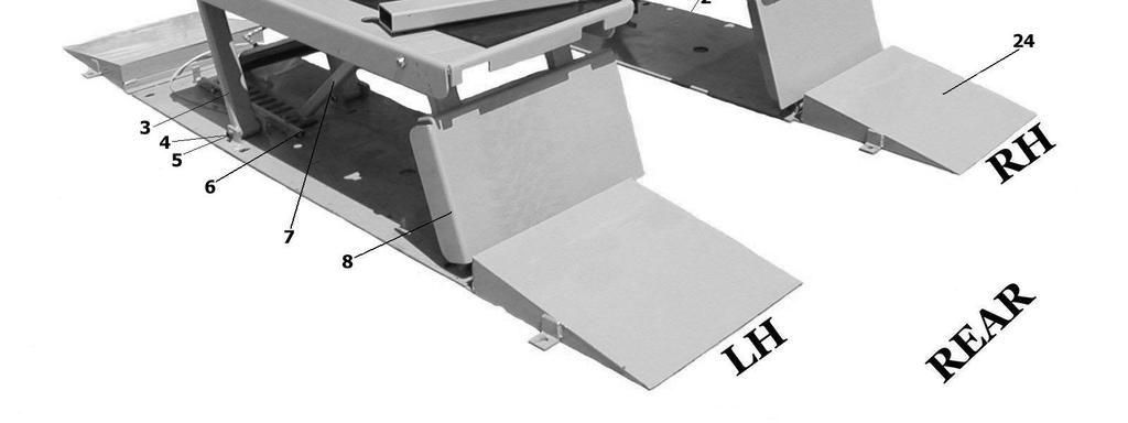
15 PARTS LIST - BLAZER 9000 Only use manufacturer supplied replacement parts ITEM# PART# Description QTY TOP PLATE STRUCTURE LH TOP PLATE STRUCTURE RH BASE STRUCTURE - LH BASE STRUCTURE - RH 1 # ANCHOR BOLTS 5/8X3-3/ LIFTING LEG SHOULDER BOLT 3/ NYLOCK NUT-THIN 5/8-11NC L TOP SAFETY TUBE STR.- LH R TOP SAFETY TUBE STR.- RH 1 # MASTERLINK SAFETY BAR STRUCTURE- LH SAFETY BAR STRUCTURE- RH RAMP STRUCTURE- LH RAMP STRUCTURE- RH MAIN PIN NYLOCK NUT-THIN 3/4-16NF LH HYDRAULIC CYLINDER - LH RH HYDRAULIC CYLINDER - RH OUTER LIFT ARM STR INNER LIFT ARM STR LIFT PAD ASSEMBLY 4 # LIFT PAD - BOLT ON 4 # LIFT PAD STRUCTURE 4 # HEX SCREW 3/8-16NC X 3/4 8 # FLATWASHER 3/8" SAE 8 # ARM RETAINER PLUG LIFT PAD EXTENSION 5" LIFT PAD EXTENSION 2-5/8" /8 LOCK WASHER HEX SCREWS - 3/8X16NC x 1/2" HEX SCREWS - 3/8X16NC x 5/8" RUBBER PAD 2 # ELEVATOR BOLT 12 # HEX NUT 1/4 X 20NC RUBBER BLOCKS POWER UNIT POWER UNIT STAND STR. 1 # ANCHOR BOLTS 3/8 X 3-3/ DRIVE ON RAMP STRUCTURE 4 # ANCHOR BOLT 5/8" X 3-3/4" POWER SWITCH - RAISE POWER SWITCH - LOWER 1 # ALI SAFETY REQUIREMENTS FOR OPER. 1 # ALI LIFTING POINT QUICK REF. 1 # LIFTING IT RIGHT MANUAL 1 # ETL DECAL 1 # ALI UNIFORM WARNING LABELS 1 # CAUTION DECAL 1 # SERIAL NAME PLATE 1
16 16
17 HYDRAULIC SCHEMATIC SYS PART# PART NAME QTY Power Unit Elbow 1 4 NPT x 9 16 JIC HYD. Hose -26' Long (RH or LH) HYD. Hose -14' Long (RH or LH) RH HYD. Cylinder - RH Male Conn JIC x 9 16 ORB HYD.Hose 7-1 4" Male 90º 9 16 JIC Union RH HYD. Cylinder - LH 1
18
Floor Plate Style Lift And Overhead Beam Style Lift. Two Post Lift
 Floor Plate Style Lift And Overhead Beam Style Lift 9,000 POUND Two Post Lift ASSEMBLY & OPERATION INSTRUCTION TABLE OF CONTENTS Important Note Page 3 Definition Page 4 Preparation and General Information
9,000 POUND TWO-COLUMN AUTOMOTIVE LIFT. Model: NW-2-9KACD MANUAL
 9,000 POUND TWO-COLUMN AUTOMOTIVE LIFT Model: NW-2-9KACD MANUAL 1 9,000 POUND CAPACITY MODEL: NW-2-9KACD TWO-COLUMN AUTOMOTIVE LIFT READ THIS ENTIRE MANUAL BEFORE OPERATION BEGINS RECORD BELOW THE FOLLOWING
MODEL QMR6 PORTABLE MID-RISE LIFT 6,000 lb Capacity 1500 lb Per Arm INSTALLATION, OPERATION AND MAINTENANCE MANUAL
 MODEL QMR6 PORTABLE MID-RISE LIFT 6,000 lb Capacity 1500 lb Per Arm INSTALLATION, OPERATION AND MAINTENANCE MANUAL IMPORTANT!!! READ THIS MANUAL COMPLETELY BEFORE INSTALLING OR OPERATING THE LIFT 200 CABEL
Lifting height 5.5" - 72" with adapters " Height overall 165" Width between columns 122" Drive through 109" Width overall 151.
 Model Number TP12KC-D Capacity 12,000 lbs. Lifting height 5.5" - 72" with adapters 79.625" Height overall 165" Width between columns 122" Drive through 109" Width overall 151.125" Arm extension 37.5" -
Installation Instructions Capacity 10,000 lbs. (100 Series Lift)
") Installation Instructions Capacity 10,000 lbs. (100 Series Lift) IMPORTANT Reference ANSI/ALI ALIS, Safety Requirements for Installation and Service of Automotive Lifts before installing lift. OPERATING
Installation Instructions Capacity 10,000 lbs. (100 Series Lift) IMPORTANT Reference ANSI/ALI ALIS, Safety Requirements for Installation and Service of Automotive Lifts before installing lift. OPERATING
Model: TPO310-ACX MANUAL
 PEAK-AUTOLIFT 10,000 POUND TWO-COLUMN AUTOMOTIVE LIFT Model: TPO310-ACX MANUAL AutoTool 2739 W 79 th St #16 Hialeah, FL 33016 Phone: (305) 825-9600 www.autotool.net Rev. 2010 Table of Contents WARRANTY...3
2-Post Lift Operations and Maintenance Manual
 2-Post Lift Operations and Maintenance Manual Table Of Contents Safety Instructions... 2 Owner/Employer Responsibilities / Operating Conditions... 3 Operating Instructions... 4 Maintenance Instructions...
Atlas PV-9WP Addendum
 Atlas PV-9WP Addendum 9,000 lb. Capacity Two-Post Overhead Lift The Atlas PV-9WP above ground hoist is 6 inches wider than the Atlas PV-9P, giving it an overall width of 141 (11 9 ) and a drive thru width
TWO POST LIFT INSTALLATION AND OWNERS MANUAL
 TWO POST LIFT INSTALLATION AND OWNERS MANUAL DP15, DP15-2 Capacity 15,000 lbs. 1. TABLE OF CONTENTS 2. Important Information.. 2 3. Section 1 Owner s Manual Safety Instructions... 3 Monthly Maintenance...
WHIP INDUSTRIES, INC.
 WHIP INDUSTRIES, INC. WFP30R, WFP30R-E & WFP30R-EE STD., EXT. & E-EXT. 30,000 LBS CAPACITY FOUR POST ABOVE GROUND LIFT INSTALLATION INSTRUCTIONS & MANUAL WHIP INDUSTRIES, INC 3010 S MAIN ST. FORT WORTH,
CONTENTS. Product Features and Specifications Installation Requirement Installation Exploded View Operation Instruction...
 1 CONTENTS Product Features and Specifications... 3 Installation Requirement... 5 Installation... 6 Exploded View... 20 Test... 22 Operation Instruction... 25 Maintenance... 26 Trouble Shooting... 27 Parts
MID RISE. INSTALLATION and OPERATION MANUAL MODEL 6000A // 6000E 6,000 LB. CAPACITY. READ and SAVE THIS INSTRUCTION MANUAL
 INSTALLATION and OPERATION MANUAL MID RISE MODEL 6000A // 6000E 6,000 LB. CAPACITY READ and SAVE THIS INSTRUCTION MANUAL AUGUST 2005 6-0944 6500 Millcreek Drive Mississauga, Ontario Canada L5N 2W6 1-800-268-7959
Owner s Manual. SLP Hide-A-Way Tuckunder Style
 Owner s Manual SLP Hide-A-Way Tuckunder Style 10900 Kenwood Road Cincinnati, OH 45242 Ph: 513-891-6210 Toll-Free: 866-539-6261 Fax: 513-891-4901 www.leymanlift.com sales@leymanlift.com LML00302-2/05/15
SCISSOR LIFT Model MR6K-38 /161108A 6,000lb Capacity Operation Manual
 SCISSOR LIFT Model MR6K-38 /161108A 6,000lb Capacity Operation Manual (Version A) 2009. Apr. CONTENT 1. Safety Note, Caution and Warning Important Information Safety Instructions 2. Technical Manual Product
Installation Manual. LHS & LLBS Hide-A-Way Tuckunder Style
 Installation Manual LHS & LLBS Hide-A-Way Tuckunder Style 10900 Kenwood Road Cincinnati, OH 45242 Ph: 513-891-6210 Toll-Free: 866-539-6261 Fax: 513-891-4901 www.leymanlift.com sales@leymanlift.com LML00136-5/1/15
Installation Instructions Capacity 10,000 lbs. DP10 (200 Series Lift)
") Installation Instructions Capacity 10,000 lbs. DP10 (200 Series Lift) IMPORTANT Reference ANSI/ALI ALIS, Safety Requirements for Installation and Service of Automotive Lifts before installing lift. OPERATING
Installation Instructions Capacity 10,000 lbs. DP10 (200 Series Lift) IMPORTANT Reference ANSI/ALI ALIS, Safety Requirements for Installation and Service of Automotive Lifts before installing lift. OPERATING
9,000 POUND TWO-COLUMN AUTOMOTIVE LIFT Model: NW-2-9KFP MANUAL
 9,000 POUND TWO-COLUMN AUTOMOTIVE LIFT Model: NW-2-9KFP MANUAL 1 9,000 POUND CAPACITY MODEL: NW-2-9KFP TWO-COLUMN AUTOMOTIVE LIFT READ THIS ENTIRE MANUAL BEFORE OPERATION BEGINS RECORD BELOW THE FOLLOWING
Model FP12K-K Flat Deck Four-Post Lift
 Model FP12K-K Flat Deck Four-Post Lift (12,000LBS Capacity) ASSEMBLY & OPERATION INSTRUCTION 2006.4. TABLE OF CONTENTS Important Note--------------------------------------------------------------------------------Page
ATD2P11BS. Two-Post Clear Floor Bi-Symmetric Automotive Lift. Installation & Operation Manual. 11,000 lbs. Capacity. (2,750 lbs.
 Two-Post Clear Floor Bi-Symmetric Automotive Lift 11,000 lbs. Capacity (2,750 lbs. Max per Arm) Installation & Operation Manual 1. Safety Information 1.1 Note, Caution and Warning 1.2 Important Information
Owner s Manual. LTS Hide-A-Way Truck Side Gate
 Owner s Manual LTS Hide-A-Way Truck Side Gate 10900 Kenwood Road Cincinnati, OH 45242 Ph: 513-891-6210 Toll-Free: 866-539-6261 Fax: 513-891-4901 www.leymanlift.com sales@leymanlift.com LML00410-11/6/15
CONTENTS. Product Features and Specifications Installation Requirement Steps of Installation 4. Exploded View Test Run...
 CONTENTS Product Features and Specifications... 1 Installation Requirement... 3 Steps of Installation 4 Exploded View... 14 Test Run... 16 Operation Instruction... 19 Maintenance... 20 Trouble Shooting...
Read this entire manual before operation begins.
 Read this entire manual before operation begins. Record below the following information which is located on the serial number data plate. Serial No. Model No. Date of Installation Contents Specifications.............
Parallel Lift Rack MODEL RM
 Form 4401T, 09-03 Supersedes Form 4401T, 10-00 OPERATION INSTRUCTIONS Parallel Lift Rack MODEL RM Copyright 1998-2003 Hunter Engineering Company Contents 1. For Your Safety... 1 1.1 Warning/Instruction
Read this entire manual before operation begins.
 Read this entire manual before operation begins. Record below the following information which is located on the serial number data plate. Serial No. Model No. Date of Installation Contents Specifications.............
INSTALLATION & OPERATION MANUAL
 Two-Post Clear Floor Lift (Asymmetric) 9,000 lbs. Capacity (2,250 lbs. Max per Arm) INSTALLATION & OPERATION MANUAL IMPORTANT NOTES READ THE INSTALLATION AND OPERATION MANUAL IN ITS ENTIRETY BEFORE ATTEMPTING
If facility voltage is different, refer to set-up instructions. IMPORTANT This lift is wired and adjusted to operate at 230 volts.
 MODEL 40/50K Installation And Owner s Manual (000Series) Capacity 40,000 lbs. (20,000 lbs. per axle) Capacity 50,000 lbs. (25,000 lbs. per axle) Four Post Surface Mounted Lift IMPORTANT This lift is wired
Installation Instructions X-Force UTV Lift (000 Series) Capacity 2,275 lbs (1,035 kg)
 Capacity 2,275 lbs (1,035 kg)") Installation Instructions X-Force UTV Lift (000 Series) Capacity 2,275 lbs (1,035 kg) Read entire manual before assembling, installing, operating, or servicing this equipment. LP20640 IN20793 September
Installation Instructions X-Force UTV Lift (000 Series) Capacity 2,275 lbs (1,035 kg) Read entire manual before assembling, installing, operating, or servicing this equipment. LP20640 IN20793 September
SL210i/SL212i/SL19i. Table Of Contents
 SL210i/SL212i/SL19i (700 Series) SL19i Capacity 9,000 lbs. SL210i Fixed Pad Capacity 9,000 lbs. SL210i Capacity 10,000 lbs. SL212i Capacity 12,000 lbs. Table Of Contents Owner/Employer Responsibilities...
MIDRISE MODEL SM60F_1 // SM60F_A 6,500 LB. CAPACITY
 INSTALLATION and OPERATION MANUAL READ THIS INSTRUCTION MANUAL THOROUGHLY BEFORE INSTALLING, OPERATING, SERVICING OR MAINTAINING THE LIFT. SAVE THIS MANUAL. NOV 2007 REV.B MIDRISE MODEL SM60F_1 // SM60F_A
TWO POST LIFT INSTALLATION AND OWNERS MANUAL. January 2008 rev. E I MAN
 TWO POST LIFT INSTALLATION AND OWNERS MANUAL DP15, DP15-2 Capacity 15,000 lbs. January 2008 rev. E 1. TABLE OF CONTENTS 2. Important Information.. 2 3. Section 1 Owner s Manual Safety Instructions... 3
ATD-2P9A 9,000 lbs. Two Post Clear Floor Lift Owner s Manual
 ATD-2P9A 9,000 lbs. Two Post Clear Floor Lift Owner s Manual Features: Specifications: IMPORTANT NOTES READ THE INSTALLATION AND OPERATION MANUAL IN ITS ENTIRETY BEFORE ATTEMPTING TO INSTALL THE LIFT.
Model FP14KA-C Alignment Four-Post Lift
 Model FP14KA-C Alignment Four-Post Lift (14000 LBS Capacity) ASSEMBLY & OPERATION INSTRUCTION 2006.4. TABLE OF CONTENTS Important Note--------------------------------------------------------------------------------Page
Read this entire manual before operation begins.
 Read this entire manual before operation begins. Record below the following information which is located on the serial number data plate. Serial No. Model No. Date of Installation Contents Specifications.............
IMPORTANT INFORMATION
 TABLE OF CONTENTS IMPORTANT INFORMATION... 2 LIFT AREA LAYOUT INFORMATION... 3 TOOLS and EQUIPMENT REQUIRED FOR INSTALL... 4 INSTALLATION PROCEDURE... 5 FOUNDATION and ANCHORING REQUIREMENTS... 6 DEFINITION
Read this entire manual before operation begins.
 Read this entire manual before operation begins. Record below the following information which is located on the serial number data plate. Serial No. Model No. Date of Installation Contents Important Information........
Read this entire manual before operation begins.
 Read this entire manual before operation begins. Record below the following information which is located on the serial number data plate. Serial No. Model No. Date of Installation Contents Specifications.............
Challenger Lifts, Inc. MODEL 12000
 Challenger Lifts, Inc. MODEL 12000 TWO POST SURFACE MOUNTED LIFT OPERATION, INSTALLATION & MAINTENANCE MANUAL IMPORTANT READ THIS MANUAL COMPLETELY BEFORE INSTALLING OR OPERATING THE LIFT 200 CABEL STREET,
SPO15, SPO18 I N S T A L L A T I O N I N S T R U C T I O N S
 SPO15, SPO18 Sprinter SPO15 (3A0 Lifts) Capacity 11,000 lbs. Standard SPO15 (300 Series Lifts) Capacity 15,000 lbs. Standard SPO18 (300 Series Lifts) Capacity 18,000 lbs. SPO15 (31A0 Lifts) Capacity 14,300
Motorcycle Lift 1,000 lbs. capacity Installation, Safety, Operation, Maintenance
 Motorcycle Lift 1,000 lbs. capacity Installation, Safety, Operation, Maintenance Entire contents 2008 by RL Consolidated, Inc. All rights reserved. 994358 CO7297 Rev. F 12/17/2008 Inspection upon receipt
MODEL SCA Installation and Operation Manual Important:
 MODEL SCA Installation and Operation Manual Important: This manual contains specific cautionary statements relative to worker safety. Read this manual thoroughly and follow as directed. It is impossible
Operation Guide. Operation Guide. Winnebago Hydraulic Leveling Systems by Kwikee. Introduction. Table of Content WARNINGS
 Operation Guide 05/07 Kwikee #1422192 Rev. 0F Table of Content Page Introduction 1 Safety Information 1 Operation 2 Control Panel 3 Manual Leveling 3 Automatic Leveling 3 Remote Operation 4 Stabilizing
ATO7 (100 Series Lifts)
") O PE ATO7 (100 Series Lifts) Capacity 7000 lbs. (3181 kg) 1750 lbs. (795.25 kg) per arm R A TI O N & M AI N TE N A N N CE Table Of Contents Safety Instructions... 2 Owner/Employer Responsibilities / Operating
O PE ATO7 (100 Series Lifts) Capacity 7000 lbs. (3181 kg) 1750 lbs. (795.25 kg) per arm R A TI O N & M AI N TE N A N N CE Table Of Contents Safety Instructions... 2 Owner/Employer Responsibilities / Operating
ATTENTION. 1. Do not attempt to use the power unit to extend your cylinder. This must be done manually.
 NSS8XLT Installation Manual ATTENTION By following the instructions in this manual you can save yourself much time, frustration and money. The installation of your lift will take 4-5 hours. Do not rush.
ASSEMBLY & OPERATION INSTRUCTION MANUAL
 Sliding Bridge Jack 3,500 lbs. Capacity ASSEMBLY & OPERATION INSTRUCTION MANUAL TABLE OF CONTENTS Specifications... 2 Description & Features... 3 Installation Instructions... 4 Safety Instructions... 4
Models PR-12F PR-12C PR-15C SURFACE MOUNTED TWO-POST LIFTS INSTALLATION AND OPERATION MANUAL
 Forward this manual to all operators. Failure to operate this equipment as directed may cause injury. INSTALLATION AND OPERATION MANUAL SURFACE MOUNTED TWO-POST LIFTS Models PR-12F PR-12C PR-15C Keep this
TP15KC-KX Two-Post Clear Floor Lift
 TP15KC-KX Two-Post Clear Floor Lift (Symmetric) 15,000 lbs. Capacity (3,750 lbs. Max per Arm) ASSEMBLY & OPERATION INSTRUCTION MANUAL Feb. 2017 IMPORTANT NOTES READ THE INSTALLATION AND OPERATION MANUAL
INSTALLATION, OPERATION & MAINTENANCE MANUAL
 INSTALLATION, OPERATION & MAINTENANCE MANUAL Two Post Surface Mounted Lift MODEL X10 10,000 LBS. CAPACITY 2500 LBS. PER ARM 200 Cabel Street, P.O. Box 3944 Louisville, Kentucky 40201-3944 Email:sales@challengerlifts.com
PowerLevel s e r i e s
 Owner s Manual Hydraulic Leveling CONTENTS Introduction Operation Control Panel Automatic Leveling Manual Leveling Retracting Jacks Remote Operation Care & Maintenance Troubleshooting Error Codes 1 2 2
Read this entire manual before operation begins.
 Read this entire manual before operation begins. Record below the following information which is located on the serial number data plate. Serial No. Model No. Date of Installation Contents Specifications.............
SPOA10NB, SPOA10, SPO10 ( Series Lifts) SPOA7, SPOA9, SPO9 (500 Series Lifts)
 SPOA7, SPOA9, SPO9 (500 Series Lifts)") O PE SPOA10NB, SPOA10, SPO10 (200-700 Series Lifts) SPOA7, SPOA9, SPO9 (500 Series Lifts) SPOA7 Capacity 7,000 lbs. SPOA9, SPO9 Capacity 9,000 lbs. SPOA10NB, SPOA10, SPO10 Capacity 10,000 lbs. R A TI O
O PE SPOA10NB, SPOA10, SPO10 (200-700 Series Lifts) SPOA7, SPOA9, SPO9 (500 Series Lifts) SPOA7 Capacity 7,000 lbs. SPOA9, SPO9 Capacity 9,000 lbs. SPOA10NB, SPOA10, SPO10 Capacity 10,000 lbs. R A TI O
Read this entire manual before operation begins.
 Read this entire manual before operation begins. Record below the following information which is located on the serial number data plate. Serial No. Model No. Date of Installation Contents Specifications.............
Drop Tail Motorcycle Lift 1,000 lbs. capacity Installation, Safety, Operation, Maintenance
 Drop Tail Motorcycle Lift 1,000 lbs. capacity Installation, Safety, Operation, Maintenance Entire contents 2009 by Direct Lift. All rights reserved. IN50012 CO7338.1 Rev. B 03/30/2009 Inspection upon receipt
OPERATOR S MANUAL 7(5 & ( 8&. $5.00 P/N REV.B
 OPERATOR S MANUAL &281 2817( 7(5 %$/$1&( /,)7 7758& 8&. $5.00 P/N 901345 REV.B As a lift truck operator, you are responsible for a machine that is useful, powerful, and can be hazardous if not operated
Post Driver Attachment
 Attachment (Shown with Optional Power Cell Rotator) Models - 600, 850 Safety Instructions This safety alert symbol indicates important safety messages in this manual. When you see this symbol, carefully
ATD-4P14CCA 14,000 lb Capacity Closed Front Alignment Lift ASSEMBLY & OPERATION INSTRUCTION MANUAL
 ATD-4P14CCA 14,000 lb Capacity Closed Front Alignment Lift ASSEMBLY & OPERATION INSTRUCTION MANUAL 14,000 LB. FOUR POST CABLE DRIVEN ALIGNMENT LIFT ATD-4P14CCA 14,000 lb. capacity Four post Cable driven
INSTALLATION AND OPERATION MANUAL
 AIR-HYDRAULIC ROLLING JACKBEAM CAPACITY: 5000 LBS. MODELS: EELR503A INSTALLATION AND OPERATION MANUAL READ ALL INSTRUCTIONS THOROUGHLY BEFORE INSTALLING, OPERATING, SERVICING, OR MAINTAINING THE LIFT.
Challenger Lifts, Inc. MODELS & 18000
 Challenger Lifts, Inc. MODELS 15000 & 18000 TWO POST SURFACE MOUNTED LIFT OPERATION, INSTALLATION & MAINTENANCE MANUAL IMPORTANT READ THIS MANUAL COMPLETELY BEFORE INSTALLING OR OPERATING THE LIFT 200
It is the shop owner's responsibility to train all operators in lift operation and safety.
 2 Your new lift will provide years of dependable service if installed, operated and maintained properly. Read and be prepared to follow all safety, installation, operation, and maintenance instructions
MODEL L401 & L404 Four-Post Lift
 Form 3521T, 04-00 Supersedes 3521T, 06-99 OPERATION INSTRUCTIONS MODEL L401 & L404 Four-Post Lift Copyright 1991 Hunter Engineering Company Contents 1. For Your Safety... 1 1.1 Introduction... 1 Decal
10K 2 POST IN-GROUND 40HP210ES
 INSTALLATION and OPERATION MANUAL 10K 2 POST IN-GROUND 40HP210ES READ THIS INSTRUCTION MANUAL THOROUGHLY BEFORE INSTALLING, OPERATING, SERVICING OR MAINTAINING THE LIFT. SAVE THIS MANUAL. NOV 2009 REV.
Pick Up Broom OWNERS/OPERATORS MANUAL. Model Number. Serial Number. Date of Manufacture. To Serial # Phone:
 Pick Up Broom OWNERS/OPERATORS MANUAL Model Number. Serial Number. Date of Manufacture. To Serial #039 Phone: 77-37-6 //0 Warranty Skid Pro products are warranted to be free from defects, in workmanship,
Tailgates By THIEMAN WT20, 30 & 40 PLEASE READ AND UNDERSTAND THE CONTENTS OF THIS MANUAL BEFORE OPERATING THE EQUIPMENT. HIEMAN
 WEIGHTLIFTER Tailgates By THIEMAN WT20, 30 & 40 OWNERS MANUAL/PARTS LIST! IMPORTANT! KEEP IN VEHICLE! PLEASE READ AND UNDERSTAND THE CONTENTS OF THIS MANUAL BEFORE OPERATING THE EQUIPMENT. NATIONAL TRUCK
CONTENTS. Product Features and Specifications...1. Installation Requirement...3. Steps of Installation...4. Exploded View Test Run...
 TP10AS 2-POST LIFT CONTENTS Product Features and Specifications...1 Installation Requirement...3 Steps of Installation...4 Exploded View...24 Test Run....28 Operation Instruction...29 Maintenance...30
jegs.com. Installation Instructions for Ton Aluminum Floor Jack
 Installation Instructions for 80077 3-Ton Aluminum Floor Jack Contents: Specifications Warning Information Setup and Operating Instructions Preventive Maintenance and Troubleshooting Hydraulic Maintenance
Operating Instructions - Electric Pow'r-Riser Models
 ADivisionOf Templeton, Kenly& Co., Inc. Operating Instructions - Electric Pow'r-Riser Models Table of Contents 1.0 Recieving Instructions 2.0 Safety 3.0 Specifications 4.0 Initial Installation Before Operating
6602LP CAPACITY: 2 TON LOW RIDER SERVICE JACK
 CONTENTS: Page 1 Specifications 2 Warning Information 3 Setup Instructions 4 Operating Instructions, Preventative Maintenance, Inspection and Proper Storage 5 Hydraulic Jack Maintenance Guide and Regular
FOUR-POST LIFT. 14,000 lbs. Capacity
 FOUR-POST LIFT 14,000 lbs. Capacity Note: At the rated capacity of 14,000 lbs. lift was designed for: 101" Minimum wheelbase for models without rolling jacks 124" Minimum wheelbase for models with rolling
CONTENTS. Product Features and Specifications...1. Installation Requirement Steps of Installation.. 5. Exploded View Test Run...
 CONTENTS Product Features and Specifications...1 Installation Requirement... 3 Steps of Installation.. 5 Exploded View...18 Test Run...21 Operation Instruction...22 Maintenance... 23 Trouble Shooting...
2 TON CAPACITY PROFESSIONAL SERIES ALUMINUM JACK OWNER'S MANUAL SPECIFICATIONS
 80006 OWNER'S MANUAL CONTENTS: Page 1 Specifications 2 Warning Information 3 Setup, Operating and Preventative Maintenance 4 Troubleshooting 5 Maintenance 6 Exploded View Drawing and Replacement Parts
INSTRUCTIONS AND PARTS LIST FOR MODEL FORCE 10DA and FORCE 25DA (Double Acting, Electrically-Operated Hydraulic Press)
") INSTRUCTIONS AND PARTS LIST FOR MODEL FORCE 10DA and FORCE 25DA (Double Acting, Electrically-Operated Hydraulic Press) Operation 1. Plug power cord into a 115-volt A.C. single phase 60-cycle grounded,
INSTRUCTIONS AND PARTS LIST FOR MODEL FORCE 10DA and FORCE 25DA (Double Acting, Electrically-Operated Hydraulic Press) Operation 1. Plug power cord into a 115-volt A.C. single phase 60-cycle grounded,
Railgates By THIEMAN TVL 125, TVL 16, TVL 125A, TVL 16A OWNERS MANUAL/PARTS LIST IMPORTANT! KEEP IN VEHICLE!
 TM TVL SERIES Railgates By THIEMAN TVL 125, TVL 16, TVL 125A, TVL 16A OWNERS MANUAL/PARTS LIST! IMPORTANT! KEEP IN VEHICLE! PLEASE READ AND UNDERSTAND THE CONTENTS OF THIS MANUAL BEFORE OPERATING THE EQUIPMENT.
Premium Supply. Direct Push. Models PCK-3530-DP PCK DP PCK-530-DP. Operator s Manual and Installation Instructions
 Direct Push Models PCK-3530-DP PCK-3530-2DP PCK-530-DP Operator s Manual and Installation Instructions Premium Supply 2038 West Interstate 30 866-934-0777 Proud members of: and June 20, 2018 Table of Contents
Operation & Service Manual
 Operation & Service Manual Model: 02-1248-0112 12 Ton Single Stage Jack 11/2004 Rev. 02 Includes Illustrated Parts Lists 1740 Eber Rd Tronair, Inc. Phone: (419) 866-6301 Holland, OH 43528-9794 www.tronair.com
TT-12 OWNERS MANUAL/PARTS LIST
 TOPLIFTER Tailgates By THIEMAN TT-12 OWNERS MANUAL/PARTS LIST SHOWN WITH OPTIONAL 2 PC. ALUMINUM PLATFORM! IMPORTANT! KEEP IN VEHICLE! PLEASE READ AND UNDERSTAND THE CONTENTS OF THIS MANUAL BEFORE OPERATING
CR30 Installation Instruction Capacity 30,000 lbs. (15,000 lbs. per axle) 235 /271 /308 Wheelbases 140 Minimum Wheelbase
 235 /271 /308 Wheelbases 140 Minimum Wheelbase") CR0 Installation Instruction Capacity 0,000 lbs. (,000 lbs. per axle) /7 /08 Wheelbases 40 Minimum Wheelbase January 009 CO70 INS0449 Rev. - /08/009 Required Clearances REAR 8' 0" Min. To Nearest Obstruction
CR0 Installation Instruction Capacity 0,000 lbs. (,000 lbs. per axle) /7 /08 Wheelbases 40 Minimum Wheelbase January 009 CO70 INS0449 Rev. - /08/009 Required Clearances REAR 8' 0" Min. To Nearest Obstruction
SPECIFICATIONS: Tank Size: 80 gallons PUMP RPMs: 1050 CFM: 40PSI; 90 PSI Max Pressure: 150 PSI Thermal overload protection
 5HP 80 GALLON TWO STAGE COMPRESSOR Models: 51866, 51870 CALIFORNIA PROPOSITION 65 WARNING: You can create dust when you cut, sand, drill or grind materials such as wood, paint, metal, concrete, cement,
Max-Upender/Tilt Series Service Manual
 Max-Upender/Tilt Series Service Manual LIFT PRODUCTS INC PO BOX 349 ELM GROVE WI 53122 262-521-5720 FAX 262-521-5725 Toll Free 877-543-8776 Model: Max-Upenders & Tilt Tables Manual No. 90185-B REVA 09/08
Installation Instructions
 Installation Instructions 2-Post Capacity 12,000 lbs. OPERATING CONDITIONS Lift is not intended for outdoor use and has an operating ambient temperature range of 41-104 F (5-40 C) IMPORTANT Reference ANSI/ALI
AUG 2011, REV.B
 6-4041 AUG 2011, REV.B 1. 1 2. OWNER / EMPLOYER OBLIGATIONS 1. The Owner/Employer shall ensure that lift operators are qualified and that they are trained in the safe use and operation of the lift using
CAB TILT HYDRAULIC SYSTEM
 OPERATION, MAINTENANCE and SERVICE INSTRUCTIONS CAB TILT HYDRAULIC SYSTEM WITH POWER-PACKER PUMP, CYLINDERS and LATCHES A division of Actuant Corporation 1-800-745-4142 1 www.powerpackerus.com Notice The
MODEL MC1500 Installation and Operation Manual Important:
 MODEL MC1500 Installation and Operation Manual Important: This manual contains specific cautionary statements relative to worker safety. Read this manual thoroughly and follow as directed. It is impossible
LAWN SPRINKLER, IRRIGATION PUMP
 LAWN SPRINKLER, IRRIGATION PUMP MODEL #, SP0P, SP5P, SP20P, EL0P, EL5P, EL20P SAFETY INFORMATION Please read and understand this entire manual before attempting to assemble, operate or install the product.
OWNERS MANUAL/PARTS LIST
 STOWAWAY Tailgates By THIEMAN Model ST-40 OWNERS MANUAL/PARTS LIST! IMPORTANT! KEEP IN VEHICLE! PLEASE READ AND UNDERSTAND THE CONTENTS OF THIS MANUAL BEFORE OPERATING THE EQUIPMENT. NATIONAL TRUCK EQUIPMENT
Operation Guide. Hydraulic Leveling Systems #2000, #2010, #3000, and # Table of Content. Introduction
 Operation Guide Operation Guide Hydraulic Leveling Systems #2000, #2010, #3000, and #30130 Table of Content Page Introduction 1 Safety Information 1 Operation 2 Control Panel 3 Manual Mode 3 Auto Mode
Model ET 5000W Operation and Service Manual
 Model ET 5000W Operation and Service Manual Patented 5/16 BALL Load Capacity: 5000 lbs The ET 5000W ESCALATE TRAILER offers ground level roll-on loading and roll-off unloading of equipment with non-tilting
M16, 20, 25, 30 MLB16, 20, 25, 30 OWNERS MANUAL/PARTS LIST
 STOWAWAY Tailgates By THIEMAN M16, 20, 25, 30 MLB16, 20, 25, 30 OWNERS MANUAL/PARTS LIST! IMPORTANT! KEEP IN VEHICLE! PLEASE READ AND UNDERSTAND THE CONTENTS OF THIS MANUAL BEFORE OPERATING THE EQUIPMENT.
Railgates By THIEMAN VL-30, 40, 50 OWNERS MANUAL/PARTS LIST IMPORTANT! KEEP IN VEHICLE!
 VL SERIES Railgates By THIEMAN VL-30, 40, 50 OWNERS MANUAL/PARTS LIST! IMPORTANT! KEEP IN VEHICLE! PLEASE READ AND UNDERSTAND THE CONTENTS OF THIS MANUAL BEFORE OPERATING THE EQUIPMENT. NATIONAL TRUCK
Model 802 Center Mount Adapter For New Holland 9030 & TV140 Bi-Directional Tractors PARTS CATALOG
 Model 802 Center Mount Adapter For New Holland 9030 & TV140 Bi-Directional Tractors 1 PARTS CATALOG TABLE OF CONTENTS Frame & Tractor Linkage...2,3 Header Linkage & Float Group...4,5 Header Drive Hydraulics
Read this entire manual before operation begins.
 Read this entire manual before operation begins. Record below the following information which is located on the serial number data plate. Serial No. Model No. Date of Installation Contents Important Information........
GLO-7000 SERIES (GLO-7000 & GLO-7000XLT)
") GLO-7000 SERIES (GLO-7000 & GLO-7000XLT) 7,000 LBS. CAPACITY FOUR-POST STORAGE LIFT (BLUE) INSTALLATION & OPERATION MANUAL SERIAL NUMBER: INSTALLATION DATE: EAGLE EQUIPMENT 1-800-336-2776 (STANDARD) SHIPPING
GLO-7000 SERIES (GLO-7000 & GLO-7000XLT) 7,000 LBS. CAPACITY FOUR-POST STORAGE LIFT (BLUE) INSTALLATION & OPERATION MANUAL SERIAL NUMBER: INSTALLATION DATE: EAGLE EQUIPMENT 1-800-336-2776 (STANDARD) SHIPPING
Product Information Responsibilities of Owners Safety Instructions Warning Labels Installation Instructions...
 Table of Contents Product Information... 2 Responsibilities of Owners... 3 Safety Instructions... 4 Warning Labels... 5 Installation Instructions... 6 Electrical Installation... 7 Load Capacity... 8 Daily
WARNING TABLE 3-1: DAILY SAFETY CHECK
 III. T PSL-10 MAINTENANCE his chapter contains maintenance information for the Ricon PSL-10. The information consists of a maintenance schedule, component descriptions, electrical diagrams, fuse locations,
MOREHOUSE INSTRUMENT COMPANY, INC. 60,000 LBS CAPACITY AIRCRAFT PART NUMBER SCALE S FORCE CALIBRATION PRESS PART NO.
 INDEX 1. GENERAL SPECIFICATION AND DRAWING 804000-03... 2 2. ASSEMBLY INSTRUCTIONS... 5 3. OPERATING INSTRUCTIONS... 6 4. MAINTENANCE INSTRUCTIONS... 7 5. CERTIFICATE OF CAPACITY LOAD TEST AND OVERLOAD...
8700 Series 8900 Series Rolling Air Jacks
 8700 Series 8900 Series Rolling Air Jacks Installation, Operation & Repair Parts Information - NOTICE - AIR SUPPLY MUST HAVE IN-LINE FILTER/REGULATOR/LUBRICATOR (NOT INCLUDED) TO VALIDATE THE ROLLING AIR
Cargolift 85 Pv Repair. Cargolift 90 Sa Standard. Cargolift 120 Saav Jumbo. Cargolift 120 F Drive-on IMPORTANT
 Installation, Operation and Maintenance Manual For Cargolift 85 Pv Repair Cargolift 90 Sa Standard Cargolift 120 Saav Jumbo Cargolift 120 F Drive-on IMPORTANT Read this manual throughoutly before installing,
M/MLB/MDC/MDC LB 25, 30 OWNERS MANUAL/PARTS LIST
 TM STOWAWAY Tailgates By THIEMAN M/MLB/MDC/MDC LB 25, 30 OWNERS MANUAL/PARTS LIST M-25 SHOWN! IMPORTANT! KEEP IN VEHICLE! PLEASE READ AND UNDERSTAND THE CONTENTS OF THIS MANUAL BEFORE OPERATING THE EQUIPMENT.
TWO POST LIFT 7,000 LBS.
 R TWO POST LIFT 7,000 LBS. Model 46299 ASSEMBLY AND OPERATING INFORMATION 3491 Mission Oaks Blvd., Camarillo, CA 93011 Visit our Web site at http://www.harborfreight.com Copyright 2002 by Harbor Freight
STACKER INSTRUCTION MANUAL
 STACKER INSTRUCTION MANUAL The Mobile Stackers are lifting devices featuring easy, flexible, reliable and safe operation suitable for transportation of loads in such applications as warehouses, manufacturing
TWO POST LIFT INSTALLATION AND OWNERS MANUAL Capacity 10,000 lbs.
 TWO POST LIFT INSTALLATION AND OWNERS MANUAL Capacity 10,000 lbs. May 2009 All rights reserved. CO7378.2 IN60005 Rev. - 5/7/2009 TABLE OF CONTENTS Important Information...2 Section 1 Owner s Manual Safety
Page 1 of 17. Part# M0200 Rev.11 7/29/2016
 Part# M0200 Rev.11 7/29/2016 This manual contains important information concerning the installation and operation of the product listed above. Read manual thoroughly and keep for future reference INSTRUCTIONS