125cc LEOPARD TaG engine 2003
|
|
|
- David Gregory
- 5 years ago
- Views:
Transcription

1 125cc LEOPARD TaG engine 2003 ASSEMBLY INSTRUCTIONS and USER MANUAL 18/10/02 mod. C MAN-016 D
2 INDEX GENERAL DESCRIPTION OF THE "LEOPARD" ENGINE CHARACTERISTICS OF THE "LEOPARD" ENGINE OPERATIONAL LIMITS 1- Contents of the packing 2- Motor identification Number 3- Preparation and installation of the engine on the chassis 3.1 Install the water cooling system 3.2 Exhaust header assembly 3.3 Preparation and installation of the motor-mount 3.4 Install the carburetor 3.5 Install the engine on the chassis 3.6 Install the clutch cover with H.T. coil 3.7 Installation and connection of the power pack box 3.8 Electrical connections on the engine 3.9 Installation of the intake silencer 3.10 Install the exhaust Page GASOLINE and OIL 5- Carburetor Adjustment guide 6- Starting and stopping the engine 7- Engine break-in 8- Inlet silencer 9- Exhaust system 10- Centrifugal clutch 11- Instructions for the assembly/disassembly of the clutch 12- Battery 13- Spark plug and thermal degree 14- Choice of the best sprocket ratio 15- Scheduled maintenance 16- Troubleshooting 17- Engine and accessories preservation Attachments: - Fastener Torque Table - Wiring diagram
3 GENERAL DESCRIPTION OF THE "LEOPARD" ENGINE This engine of the "TaG" series (Touch and Go) has been expressly designed and developed for the powering of karts for hobby racing on closed tracks, destined for this specific purpose. When designing this new line of engines, the technical solutions already adopted for the high performance engines were used, in order to guarantee the highest reliability of components, when the operating limitations are respected. The motor is a single cylinder using the two stroke principle. The cylinder and the crankcase are in aluminium alloy. The pressed in liner is made of centrifugated cast iron, fully machined to guarantee the best possible stability. The head is separated from the cylinder and secured by studs. The crankshaft is built and supported by two ball-bearings. The crankshaft is of steel alloy, hardened and tempered, as is the connecting rod which runs on roller bearings. The igniton includes a 4 pole stator/rotor with integral pick-up, an H.T. coil and an electronic unit with micro-processor (Power-Pack), complete with wiring harness. The main features of the ignition are: - During the start of the engine, the power-pack activates a booster which increases the spark energy to facilitate the starting of the engine. - The ignition system permits, through the electronic unit, the onboard battery recharging during the normal use of the engine. - The spark is generated also without a battery: it is therefore possible, in case of emergency, to start the engine with an external starter unit. The engine has an integrated electric starter; by pushing the green start button the starter activates a bendix type gear which engages the starter ring assembled on the clutch. The engine is provided with an automatic dry centrifugal clutch with low maintenance and with interchangeable sprocket. The carburetor is a diaphragm Tillotson carburetor with integral fuel pump, filter and all position mounting capability. The battery (12 V- 7.2Ah) is a sealed, no maintenance battery and is supplied already preassembled in the Power Pack support box which can be easily adapted to all existing chassis. The exhaust, included in the supply, is already tuned for the best possible performance. The engine is supplied with a kit which includes the radiator, the pump, water hoses and whatever necessary for the assembly on the kart. 1
4 CHARACTERISTICS OF THE "LEOPARD" ENGINE - OPERATIONAL LIMITS 1. The characteristics of the engine are the following : Cycle: Original cubic capacity: Original bore: Max. theoretical bore: Stroke: Lubrication : Induction: Carburetor: Cooling : Ignition: Battery charge: Electric start: Clutch: OTTO / 2 stroke cc mm mm mm Fuel-Oil mix Reed valve Membrane, Tillotson water Digital / 4 poles with internal rotor With integral generator 12V/0.30 Kw Automatic, dry, centrifugal 2. OPERATIONAL LIMITS: Max. RPM : RPM Min. watertemperature: 45 c Max. water Temperature: 90 c Never exceed the above limits, no obligation of IAME exists in case the above limits are exceeded. 2
5 1- CONTENT OF THE PACKING Each Leopard engine is delivered with the under shown accessories: -125 cc LEOPARD- TaG engine EXHAUST Flexible 1 Spring For Flexible 3 Exhaust Fiber Strip 1 Exhaut Header 1 Exhaust Muffler 1 INDUCTION Tillotson Carburetor 1 Intake Silencer 1 Intake Silencer Support 1 Accelerator Cable Bracket 1 ELECTRICAL Battery 12 V 1 Battery Support 1 Battery Strap 1 Battery Clamps 2 Power Pack Box with Harness 1 Plastic Fixing Clamps 8 NGK BR 10 EG Spark Plug 1 Spark Plug Cap 1 MISCELLANEOUS Additional Engine Plate 1 Water proof cover 1 Clutch cover with H.T. coil 1 WATER COOLING Radiator 1 Radiator Support Kit 1 Complete Hose Kit 1 Pump, complete 1 3
 The number normally includes a letter followed by 4 digits (there can be exceptions in some special cases).")
6 2- MOTOR IDENTIFICATION NUMBER The official motor identification number can be found stamped in the lower left part of the crankcase, next to the electric starter (see fig.) The number normally includes a letter followed by 4 digits (there can be exceptions in some special cases). Other numbers stamped on the crankcase or other surfaces of the motor refer to various manufacturing processes and do not identify the motor. NOTE: In case of need for spares and when contacting the IAME Support Centers, please always refer to the Motor Identification Number and to the motor model. 4


 ON THE PUMP BRACKET ON THE REAR CROSS RAIL (SEE FIG. 1).")
7 3- PREPARATION AND INSTALLATION OF THE ENGINE ON THE CHASSIS NOTE: In case the engine is supplied already assembled on the chassis, it is at care of the assembler to follow these instructions. The final customer, in this case, can skip this section and can start reading from section 4. Whenever the engine or a component is disassembled, it is necessary to always follow the under shown instructions for proper reassembly INSTALL THE WATER COOLING SYSTEM NOTE: To install the water pump belts it is necessary to remove the rear axle. 1 2 REINSTALL THE REAR AXLE AFTER HAVING INSERTED THE TWO BELTS. SUGGESTION: INSTALL OTHER TWO BELTS AS SPARES AND FIX THEM WITH TAPE TO THE AXLE. INSTALL THE WATER PUMP (1 SCREW M6 X 45 WITH WASHER AND SELF LOCKING NUT) ON THE PUMP BRACKET ON THE REAR CROSS RAIL (SEE FIG. 1). IN CASE THERE IS NO BRACKET FOR THIS PURPOSE IT I S NECESSARY TO INSTALL THE PUMP ON REMOVABLE CLAMPS AVAILABLE IN DIFFERENT DIAMETERS ( 28/30/32mm) AS ACCESSORIES (SEE FIG. 2). TIGHTEN BY HAND THE SCREW ON THE PUMP LETTING IT FREE TO ROTATE FOR THE TENSIONING OF THE BELTS. Fig.1 3 INSTALL ON THE AXLE THE DRIVING PULLEY (n 2 CLAMPS AVAILABLE IN DIFFERENT DIAMETERS 30/35/40/50mm) ALIGNING ITS RACES WITH THE DRIVEN PULLEY. TIGHTEN THE CLAMPS WITH TWO SCREWS M6 X 25. Fig.2 Fig.3 5

.")

8 4 INSTALL THE BELTS AND TENSION (SEE FIG. 4). Fig.4 BEFORE INSTALLING THE RADIATOR PREASSEMBLE THE FOLLOWING COMPONENTS 5 INSERT THE RUBBER DAMPENERS INTO THE FIXING HOLES OF THE RADIATOR AND INSERT THE SPACERS (SEE FIG. 5). RUBBER DAMPENER SPACER Fig.5 6 INSERT THE BUSHES INTO THE RADIATOR SUPPORT BRACKET. PLACE THE BRACKET BETWEEN THE RADIATOR FIXINGS (SEE FIG. 6). RADIATOR SUPPORT BRACKET BUSH Fig.6 6
 (SEE FIG. 7).")
. Fig.7 SCREW M6X85 RADIATOR LOWER FIXING CLAMP Fig.")
. ONCE YOU FIND THE CORRECT POSITION, TIGHTEN ALL THE BOLTS Fig.9 10 THE KIT INCLUDES THREE RUBBER HOSES.")
9 7 FIX THE SUPPORT BRACKET TO THE RADIATOR, AND ALSO INSERT THE UPPER SUPPORT BRACKET (SCREWS M6X90 AND M6X85 WITH NUTS). PLACE THE RADIATOR LOWER FIXING CLAMP AND THE SPACER ON THE RADIATOR SUPPORT BRACKET (SCREW M8X45 WITH NUT) (SEE FIG. 7). SCREW M6X90 UPPER SUPPORT BRACKET SPACER 8 PLACE THE LOWER FIXING CLAMP ON THE CHASSIS SIDE RAIL (BRAKE SIDE) (N 2 SCREWS M8X45 WITH NUTS) TIGHTEN THE BOLTS BY HAND (SEE FIG. 8). Fig.7 SCREW M6X85 RADIATOR LOWER FIXING CLAMP Fig.8 9 PLACE THE RADIATOR SO THAT THE HOLE, ON THE UPPER RADIATOR BRACKET, AND ONE OF THE UPPER HOLES ON THE BEARING SUPPORT BOX, MATCH (SEE FIG. 9). ONCE YOU FIND THE CORRECT POSITION, TIGHTEN ALL THE BOLTS Fig.9 10 THE KIT INCLUDES THREE RUBBER HOSES. CONNECT THE FIRST HOSE TO THE FITTING ON THE RADIATOR INLET AND THE FITTING ON THE ENGINE OUTLET, TIGHTEN WITH STEEL CLAMPS (SEE FIG.10). 7

10 11 CONNECT THE SECOND HOSE BETWEEN THE FITTINGS ON THE RADIATOR OUTLET AND THE PUMP INLET. CONNECT THE THIRD HOSE BETWEEN THE FITTINGS ON THE PUMP OUTLET AND THE ENGINE INLET (SEE FIG. 10). TIGHTEN WITH STEEL CLAMPS. Fig.10 BEFORE STARTING THE ENGINE FOLLOW THESE RECOMMENDATIONS: Unscrew the cap on the radiator and loosen the breather plug on the engine head. Fill the radiator until the water comes out from the plug on the head (there is no air in the system now) and the radiator is completely filled. Tighten the cap (the system contains appr. 1 lt. of water). It is advisable to put a small cup to recover water from the breather on the cap in case of boiling water. After the engine run-in, check the water level in the radiator and top up if necessary. 8
. Fig.1 3.2.3 INSTALL THE WASHERS SUGGESTION: PUT THE ENGINE IN HORIZONTAL POSITION AND SET INTO POSITION THE WASHERS WITH A SCREWDRIVER.")
11 3.2 EXHAUST HEADER ASSEMBLY NOTE: THE ENGINE IS SUPPLIED WITH THE EXHAUST GASKET AND NUTS ALREADY INSERTED. WHEN THE SHIPMENT IS MADE AN EXHAUST COVER TO PROTECT THE INTERNAL PARTS REMOVE THE NUTS AND THE EXHAUST COVER MAKE SURE THE EXHAUST GASKET IS SEATED AND INSTALL THE EXHAUST HEADER (SEE FIG 1). Fig INSTALL THE WASHERS SUGGESTION: PUT THE ENGINE IN HORIZONTAL POSITION AND SET INTO POSITION THE WASHERS WITH A SCREWDRIVER INSTALL THE THREE NUTS. TORQUE AT 9 11 Nm ( in-lb) 10 mm SOCKET WRENCH (OR 10 mm OPEN WRENCH.) 3.3 PREPARATION AND INSTALLATION OF THE MOTOR MOUNT NOTE: ALL DIMENSIONS ARE IN MILLIMETERS DRILL 4 HOLES (DIAM. 8.5mm) IN THE MOTOR MOUNT. 9
. Fig.2 3.3.3 INSTALL THE MOTOR MOUNT.")
")
 3.4 INSTALL THE CARBURETOR 3.4.1 INSTALL THE GAS CABLE CLAMP ON THE SUPPORT (SEE FIG.")
12 3.3.2 BEFORE INSTALLING THE MOTOR MOUNT, POSITION THE ADDITIONAL MOUNT PLATE ON THE CRANKCASE (SEE FIG. 2). Fig INSTALL THE MOTOR MOUNT. MAKE SURE TO USE M8 ALLEN SCREWS WITH A LENGHT SUCH AS TO ENGAGE, IN THE CRANKCASE, A THREADED PORTION LENGHT OF 16 19mm (THE SCREW MUST PROTRUDE FROM THE PLATE FOR 16 19mm) (SEE FIG. 3 AND DRAW. PAG. 9) 6 mm ALLEN WRENCH. Fig.3 4 ALLEN SCREWS M8 TORQUE AT Nm ( in-lb) 3.4 INSTALL THE CARBURETOR INSTALL THE GAS CABLE CLAMP ON THE SUPPORT (SEE FIG. 4) 12 POINT WRENCH 10mm Fig.4 10
 (SEE FIG. 5).")


.")
13 3.4.2 REMOVE 2 SCREWS 3.5mm ON THE CARB. PUMP (IN CORRESPONDENCE OF THE THROTTLE LEVER) (SEE FIG. 5). SCREWDRIVER 4.8 mm. Fig INSERT THE GAS BRACKET AND THE TWO SCREWS (SEE FIG. 6). Fig INSTALL THE INTAKE SUPPORT 2 SCREWS M5 X10 (SEE FIG. 7) 3 mm ALLEN WRENCH Fig INSTALL THE CARBURETOR (SEE FIG. 8 / 9). 10MM OPEN WRENCH REMOVE THE TWO M6 NUTS FROM THE INLET MANIFOLD. REMOVE THE PLASTIC PLUG FROM THE INLET MANIFOLD. MAKE SURE THAT THE PRESSURE HOLE ON THE GASKET IS NOT PLUGGED. Fig.8 11

 3.")


14 WHEN REPLACING THE CARB GASKET ALWAYS MAKE SURE THAT THE GASKET IS INSTALLED SO THAT THE HOLE IN THE GASKET MATCHES WITH THE TWO PRESSURE HOLES IN THE CARB. AND IN THE CRANKCASE: OTHERWISE THE ENGINE WON T START. Fig.9 INSTALL THE CARBURETOR. N.2 NUTS M6 AND TWO WASHERS. TORQUE AT 6 10 Nm (50 90 in-lb) 3.5 INSTALL THE ENGINE ON THE CHASSIS POSITION THE ENGINE ON THE 2 OUTSIDE MAIN RAILS AND FIX THE MOTOR- MOUNT WITH THE TWO CLAMPS (SEE FIG.10) SUGGESTION: NEVER TORQUE COMPLETELY THE CLAMPS UNTIL THE CHAIN IS INSTALLED AND PROPERLY ALIGNED. Fig CHECK THE ALIGNMENT OF THE ENGINE SPROCKET AND THE AXLE SPROCKET WITH A STRAIGHT EDGE (SEE FIG. 11). Fig INSTALL THE CHAIN (PITCH: # 219) (SEE FIG. 12). Fig.12 12
 MEASURED IN THE SHOWN POINT (SEE FIG. 13) 15mm Fig.13 3.6 3.5.5 TORQUE THE CLAMP SCREWS INSTALL THE CLUTCH COVER WITH H.")
. TORQUE THE 3 SCREWS AT 8 10 Nm (70 90 in-lb) 5mm ALLEN ALWAYS MAKE SURE THAT THE GROUND CABLE ALWAYS CONNECTS THE")

15 3.5.4 MOVE THE ENGINE ON THE RAILS AND OPTIMIZE THE CHAIN TENSION. THE PLAY OF THE CHAIN MUST BE APPR. 15mm (½ ¾ inch) MEASURED IN THE SHOWN POINT (SEE FIG. 13) 15mm Fig TORQUE THE CLAMP SCREWS INSTALL THE CLUTCH COVER WITH H.T. COIL REMOVE THE 3 SCREWS M6 X 30 ON THE CRANKCASE (SEE FIG. 14) AND INSTALL THE CLUTCH COVER WITH H.T. COIL (SEE FIG.15). TORQUE THE 3 SCREWS AT 8 10 Nm (70 90 in-lb) 5mm ALLEN ALWAYS MAKE SURE THAT THE GROUND CABLE ALWAYS CONNECTS THE COIL WITH THE ENGINE. AN INADEQUATE GROUNDING COULD DAMAGE THE IGNITION BEYOND REPAIR. THE POSITION OF THE H.T. COIL HAS BEEN CHOSEN TO BE AS FAR AS POSSIBLE FROM THE EXHAUST AS THE EXCESSIVE HEAT COULD DAMAGE THE COIL BEYOND REPAIR. Fig.14 Fig.15 13
 3.7.")
 AT THE HEIGHT OF THE SEAT.")
. FIX THE BOX WITH TWO SCREWS M6 X 10.")
16 3.7 INSTALLATION AND CONNECTION OF THE POWER PACK BOX. NOTE: THE POWER PACK BOX IS SUPPLIED ALREADY ASSEMBLED ON THE BATTERY SUPPORT (WITH BATTERY). FOR A CORRECT INSTALLATION FOLLOW THE UNDER SHOWN INSTRUCTIONS. ELECTRICAL CONNECTION (refer to the attached electrical schematic) EXTRACT THE BATTERY FROM THE SUPPORT AFTER HAVING UNLACED THE BATTERY STRAP (SEE FIG. 16). Fig POSITION THE SUPPORT CLAMPS ON THE OUTSIDE RAIL (BRAKE SIDE) AT THE HEIGHT OF THE SEAT. NOTE: DIFFERENT CLAMPS ARE AVAILABLE DEPENDING ON THE DIAMETER OF THE TUBE ON THE CHASSIS. FIX THE CLAMPS BY HAND WITH 2 SCREWS M6 X 25 (SEE FIG. 17). Fig POSITION THE BATTERY SUPPORT BOX ON THE CLAMPS MATCHING THE ATTACHMENT HOLES (SEE FIG. 18). FIX THE BOX WITH TWO SCREWS M6 X 10. MOVE THE BOX WITH THE 2 CLAMPS TO THE MOST SUITABLE POSITION. TWELVE POINT WRENCH 10mm TORQUE THE M6 SCREWS AT 8 10 Nm (70 90 in-lb) Fig.18 14


17 3.7.4 INSERT THE BATTERY STRAP (SEE FIG. 19). Fig INSERT THE BATTERY WITH TERMINALS TOWARDS THE OUTSIDE (SEE FIG. 20). SUGGESTION: NEVER CONNECT THE BATTERY UNTIL YOU ARE READY TO START THE ENGINE. SEAL THE BATTERY TERMINALS WITH PLASTIC TAPE TO AVOID THAT EVENTUAL VIBRATIONS MIGHT DISCONNECT THE TERMINALS. PAY ATTENTION NOT TO SHORT CIRCUIT THE BATTERY TERMINALS AS BATTERY COULD BE DAMAGED BEYOND REPAIR. Fig ELECTRICAL CONNECTIONS ON THE ENGINE GROUND THE POWER PACK. AN INADEQUATE GROUNDING OF THE POWER-PACK BOX COULD DAMAGE THE BOX BEYOND REPAIR. MAKE SURE TO CAREFULLY FOLLOW THE UNDER SHOWN INSTRUCTIONS POSITION THE HARNESS FROM THE POWER-PACK BOX ALONG THE CENTRAL RAIL, UNDERNEATH THE SEAT, AND TIGHTEN WITH PLASTIC CLAMPS (SEE FIG. 21). NEVER LET THE HARNESS GET IN TOUCH WITH THE GROUND OR WITH ROTATING PARTS AS IT COULD BE DAMAGED BEYOND REPAIR. Fig.21 15
.")

. Fig.")

18 3.8.3 FIX THE GROUND CABLE, FROM THE POWER-PACK, ON THE ENGINE CARTER, BY MEANS OF THE PROPER THREADED HOLE (SEE FIG. 22). THIS OPERATION IS EXTREMELY IMPORTANT AS AN UNCERTAIN GROUNDING COULD DAMAGE THE POWER PACK BOX BEYOND REPAIR. Fig CONNECT THE TERMINALS (3 AND 4 WAYS) ON THE HARNESS FROM THE POWER PACK BOX WITH THE TERMINALS ON THE CABLES FROM THE IGNITION (SEE FIG ). Fig.23 MAKE SURE THAT THE FIXING TONGUES ARE PROPERLY INSERTED TO GUARANTEE THE BEST POSSIBLE CONNECTION OF THE TERMINALS. Fig CONNECT THE CABLE TERMINAL (SINGLE), FROM THE POWER-PACK, WITH THE CABLE TERMINAL ALREADY CONNECTED TO THE STARTER (SEE FIG.25). MAKE SURE THAT THE FIXING TONGUE IS PROPERLY INSERTED TO GUARANTEE THE BEST POSSIBLE CONNECTION OF THE TERMINALS. Fig.25 16
 AND COMPLETE THE FIXING OF THE HARNESS (SEE FIG. 27). Fig.")

. Fig.")

19 3.8.6 CHEK THE ELECTRIC STARTER CABLE FIXING (SEE FIG. 26) AND COMPLETE THE FIXING OF THE HARNESS (SEE FIG. 27). Fig.26 ATTENTION : NEVER LET THE HARNESS GET IN TOUCH WITH THE GROUND OR WITH A ROTATING PART AS IT COULD BE DAMAGED BEYOND REPAIR. Fig CONNECT THE COIL CABLE FROM THE POWER PACK TO THE TERMINAL ON THE COIL (SEE FIG. 28). Fig.28 SUGGESTION: SEAL THE TERMINAL ON THE COIL WITH PLASTIC TAPE TO AVOID THAT EVENTUAL VIBRATIONS MIGHT DISCONNECT THE TERMINAL PUNCTURE THE INSULATING MATERIAL ON THE H.T. CABLE WITH THE END OF THE CAP SPRING SO THAT THE SPRING IS IN SURE CONTACT WITH THE INTERNAL WIRE (SEE FIG. 29). Fig.29 17


20 3.8.9 INSERT THE SPARK PLUG CAP ON THE SPRING (SEE FIG. 30). INSTALL THE SPARK PLUG AND THE CAP OVER THE SPARK PLUG. Fig.30 INSTALL THE SPARK PLUG INSTALL THE SPARK PLUG CAP MAKING SURE THAT THE SPRING IN THE CAP IS WELL INSERTED IN THE SPARK PLUG. 3.9 INSTALL THE INTAKE SILENCER - MAKE SURE THAT THE FILTER HAS THE INLET HOLES TOWARDS THE UPPER SIDE. - FIX THE FILTER ON THE CARB, WITH A STEEL CLAMP, AND THE FILTER TO THE CHASSIS SIDE RAILS WITH PLASTIC CLAMPS (SEE FIG ) Fig.31 Fig.32 18

 AND CONNECT THE EXHAUST. Fig.33 3.10.")
21 3.10 INSTALL THE EXHAUST NOTE: SEE SECTION 9 FOR RECOMMENDATIONS ON THE IDEAL LENGHT OF THE EXHAUST INSTALL THE FLEXIBLE (L= 65mm FLEXIBLE COMPLETELY CLOSED) AND THE EXHAUST HEADER (SEE FIG. 33) AND CONNECT THE EXHAUST. Fig INSTALL THE FIBER STRIP AROUND THE FLEXIBLE AND FIX WITH THE 3 SPRINGS (SEE FIG. 34). Fig.34 THE ENGINE IS READY TO BE STARTED 19
22 4- GASOLINE and OIL Use leaded or unleaded Premium Gasoline (92 RON+MON ) mixed with oil at 6% - (16:1). 2 Use oils containing Castor Oil which guarantees an optimized lubrication at high temperatures. As on the other hand, use of Castor Oils creates gummy residues which give origin to carbon deposits, it is necessary to check and clean, at least every 5 10 hours, the piston and the head. Our experience dictates use of oils such as: Shell Advance Racing M ELF HTX 909 ERG K KART 2T CORSE ERG K KART FORMULA Once the fuel tank is filled, make sure that gasoline reaches the carburetor before starting the engine. Never use the electric starter to suck the gasoline as this would discharge the battery. SUGGESTION: Disconnect the plastic tube on the carb. and the vent tube on the tank and pressurize the vent tube, until gasoline comes out from the tube on the carb. Make sure there is no air in the tube. Connect the tube on the carb. and on the vent. 20
: 1 1 ¼ T.O. 1 ½ T.O. Based on various factors as altitude, ambient temperature etc.")
23 5- CARBURETOR ADJUSTMENT GUIDE ( I ) THROTTLE SPEED SCREW ( H ) HIGH SPEED FUEL MIXTURE ( L ) LOW SPEED FUEL MIXTURE SCREW RICH 1 T.O. * LEAN 1 ¼ T.O. ¾ T.O. * T.O. = TURNS OPEN Normally the correct setting of the mixture screws is the following: L (close the screw completely and then open): 1 ¼ 1 ½ T.O. H (close the screw completely and then open): 1 1 ¼ T.O. 1 ½ T.O. Based on various factors as altitude, ambient temperature etc. it might be necessary to reset the carburetor to optimize the performance of the engine. - Never lean too much as lean mixture will overheat engine and cause seizure - Do not force H or L closed. It may damage the precision machined orifice and render the carb unserviceable. - The adjustment of screw must be performed with warm engine. (H) Adjust T.O. from closed to approximately: 1 ¼.T.O. (L) Adjust T.O. from closed to approximately 1 ¼ T.O (I) Close by further 1 ½ T.O. after contact with throttle lever. Start the engine and warm it. If R.P.M. too high adjust I counterclockwise until clutch is disengaged. Turn c.c.w. until max. R.P.M. is reached. Adjust further fractionally for rich idle. Trigger accelerator. If R.P.M decreases (L) Slowly adjust clockwise If R.P.M. increases Continue to turn clockwise until max. R.P.M. is reached.adjust c.c.w. fractionally for rich idle. Trigger accelerator. Engine is now idling at max. attainable R.P.M. or slightly lower on rich side. Adjust I counterclockwise until R.P.M. is reached Recheck L screw for optimum setting required. Adjust H until best possible free speed is reached. Turn clockwise for higher R.P.M. Counterclockwise for lower R.P.M. Adjust L slightly richer by 1/8 ¼ T.O. Bad acceleration Return to idle and check acceleration for quick response and smooth pick-up. Good acceleration Engine ready to operate. 21
24 6- STARTING AND STOPPING THE ENGINE Press the green button on the Power Pack. If the engine can t be started within 5 seconds (check that gas gets to the carb.) interrupt and try again after 15 seconds. Shorts and frequent tries are better than long ones. In case the engine can t be started refer to Par. 16 "Troubleshooting. The engine can be stopped by pressing the red button on the Power Pack Box. Keep the button pressed until the engine has got to a complete stop. In case of rain it is necessary to protect the Power Pack Box with the water proof plastic cover, as otherwise water by entering the box, could damage the circuits beyond repair. When weather is good, remove the cover as the eventual condensation might damage the electrical circuits. 7- ENGINE BREAK-IN The break-in of the engine must be performed following a few fundamental rules: 1. Adjust the carburetion. Start with an adjustment on the rich side. 2. Warm the engine gradually for about 5 minutes at half throttle,making some laps at low speed, gently closing and opening the carb. throttle (if a tachometer is installed never exceed RPM). Never keep the same RPM for a long time. 3. Progressively increase the speed of the kart for 5 minutes at ¾ throttle opening. Never keep the same RPM for a long time. 4. Increase the speed for 5 minutes, at max. speed on the twisty parts of the circuit and making the engine rich at half straight (cover with the hand for an instant the holes on the air filter, keeping the throttle wide open). Once the break-in is over and the engine is cold, check the torque of the exhaust header nuts as, during the break-in, the nuts tend to become loose (refer to the attached table). 8- INLET SILENCER Make sure that the inlet holes on the filter are towards the front of the kart and that they are not plugged. Make sure that the clamp on the carburetor is not loosen and that the filter is well fastened to the chassis. Once a while, clean the inside from oil deposits. If necessary remove the rubber filter union and clean it with gasoline or solvent. 22
25 9- EXHAUST SYSTEM Before every test, make sure that the flexible is not damaged. Replace if necessary. In case the flexible is damaged, metallic particles could be sucked in the engine and cause a seizure. Always make sure that the springs are well hooked and in place. In case of breakage, replace the broken spring. Never race the kart without the 3 springs in place, as otherwise the exhaust pipe could vibrate beyond control. Every hours, open the pipe end and make sure that the holes on the internal counter cone are not plugged. The best performance is achieved with a total exhaust lenght of: L = mm. Where L is measured from the flange on the exhaust header up to the first welding on the first cone of the exhaust muffler (see drawing). To achieve this dimension, the flexible (supplied with the engine) must be cut at a lenght of 65mm (flexible completely closed). Having fixed a sprocket ratio, it could be necessary to improve the engine performance either at low or at high RPM. This could be achieved by modifying the exhaust lenght. In general, by shortening the total exhaust lenght an improvement at high RPM is achieved and vice versa, by lenghtening the exhaust lenght the low RPM is improved. When testing, never exceed in lenghtening or shortening the flexible by more than 5mm per time. 10- CENTRIFUGAL CLUTCH The engine has a low maintenance dry centrifugal clutch.the following prescriptions, if carefully followed, will allow a long clutch life. When starting the engine make sure that the brake pedal is fully pressed to avoid sudden accelerations. 23
26 Once the engine is started, avoid useless accelerations which can overheat and deteriorate the clutch. Oil the chain before each tests, immediately after each race or test, check the engine sprocket. Replace if necessary. A bad alignment of the engine sprocket with the axle sprocket or the lack of oil will damage the chain and sprocket. Check the clutch: Every 5 hours of use. When metallic noises are heard inside the clutch. If the kart dragging speed exceeds 6000 RPM. Every time the clutch has overheated (presence of smoke or smell of burning). To check the clutch, you must remove the clutch cover and the clutch drum. Replace the clutch: whenever the thickness of the friction material (see drawing) is lower than 1.5mm on point A of the clutch or if the body diameter is lower than 82.5mm. whenever the external friction material in the A portion of the clutch is very rough (wear or degradation of the friction material due to overheating). In case the friction material has been totally worn out and there has been a metal contact between the clutch body and the clutch drum, it is necessary to replace the clutch drum. See drawing. A A A 24
27 11- INSTRUCTIONS FOR THE DISASSEMBLY / ASSEMBLY OF THE CLUTCH The following operations can be performed by a skilled mechanic under the conditions to have available the dedicated tools shown on the text, otherwise it is necessary to apply to an Authorized Service Center. Refer to the following drawing during the operations A A A 1 Drum nut 5 Sprocket 9 Cone safety washer 2 External washer 6 Clutch drum 10 Clutch body 3 Roller cage 7 Internal washer 11 Starter ring 4 Screw 8 Locking nut 12 Screw OPERATIONS TOOLS Clutch disassembly 1. Remove the clutch cover (3 screws M6). Allen wrench 5mm T type 2. Remove the spark plug and replace with special tool to prevent crankshaft from turning. Piston fitting : P.N Remove nut (1 nut M10). 12 Point wrench - 17 mm 4. Remove the external washer, the drum with roller bearing, the internal washer. 5. Remove the special tool from the head and using the clutch wrench, remove the 16x1 nut and the cone safety washer. Clutch wrench : P.N mm socket. Turn clockwise as nut has left thread. 6. Apply clutch puller on clutch and remove clutch with Clutch puller: P.N. B C 19mm socket. 19mm socket. 7. Remove key from shaft. 8. Remove the starter ring (3 screws M6) 10 mm socket 25
28 Before assemblying the clutch, wash with diluent the shaft taper, the connecting hole on the clutch body, the clutch drum and the starter ring. Clutch assembly 1. Install the starter ring on the clutch body by matching the 3 holes and the dragging pin. (3 screws M6) make sure to always install the Ø 7 mm dragging pin as, otherwise, the eventual kick backs could break the screws. 10 mm socket (Torque at 10 Nm) (90 in-lb) (Apply Loctite on the threads) 2. Insert key on shaft. 3. Install clutch body and the cone safety washer. 4. Install the 16 x 1 nut using the clutch wrench. turn counterclockwise as nut has left thread. 5. Install the internal washer. install washer with bevel towards internal part of engine. clean the roller cage and grease it before installing it on the crankshaft. 6. Install the clutch drum and the external washer. install washer with bevel towards internal part of engine. 7. Install the piston fitting to prevent the shaft from turning and install the 10 mm nut. Clutch wrench P.N mm. socket (Torque at Nm) ( in-lb) Piston fitting : P.N mm socket (Torque at Nm) ( in-lb) 8. Install the clutch cover (3 screws M 6) Allen 5 mm. (Torque at 8 10 Nm) (70 90 in-lb) 12- BATTERY The battery (12 V 7.2 Ah) is sealed and without maintenance. In order to lengthen the battery life it is necessary though to follow a few recommendations: When the tension drops below 12.6V it is necessary to recharge the battery. Max. allowed recharging current is 1.8A. The ideal recharge is achieved with an average charging current of A. (recharging time of appr. 10 h.) and at an ambient temperature between 0 and 40 C. An overcharge or an extremely quick charge with excessive current could damage the battery (the battery would tend to swell). Choose a battery charger with the following characteristics: Feed Tension: 90/250 Vac 50/60 Hz Outlet Tension: 15 V full charge 13.8 stand-by Max outlet current: 2A full charge During transportation or storage, the battery could loose its charge due to self discharge (0.1% max per day). Fully recharge battery before use. 26
29 Always connect the - (negative) terminal before and the + (positive) terminal after. Always disconnect the battery in opposite order. Recharge the battery at least once every 6 months. Never put the battery in contact with solvents, gasolines, oils, plastifiers or rags containing such elements. The external case of the battery could be damaged. Never press or bend or overheat (by welding) the battery terminals. Other recommendations Pay attention not to have free fires upon or around the battery. Never shortcircuit the terminals. Never open the battery or throw it in the fire. In case the electrolite (diluted Sulfuric acid) gets in contact with skin or clotches, immediately wash with water. In case it gets in touch with eyes, wash and apply for medical assistance. Carefully check the external case of battery and replace in case of breakages, swellings of the case or of battery cover. Before use, clean the battery from dust and check that the terminals are not oxidyzed or damaged. When the battery comes to an end never throw it in the garbage but deliver it to an authorized disposer. 13- SPARKPLUG AND THERMAL DEGREE The engine is supplied with a standard NGK BR10EG sparkplug which represents a good compromise between the needs of a good break-in and the racing needs in normal conditions. Use of different sparkplugs is possible and, as a general information, we are attaching a correspondence list among sparkplugs of other brands based on thermal degree which represents the capacity of the sparkplug to dissipate the internal heat. The colour of the various parts of the sparkplug more exposed to the combustion flames gives a good indication on the adequacy of the thermal degree and on the carburetion. It is necessary though to understand which of the two parameters has to be changed and only the experience tells how to identify the most proper thermal degree of a sparkplug as lean or rich mixtures can generate the same final look which can also be achieved with a hot or cold sparkplug. See table: An excessively warm sparkplug shows the symptoms listed aside Always use a warmer than standard spark plug with cold or rainy climates. A correct thermal degree shows: Extremely clear color, porous lock and calcification of the electrodes and of the internal insulation. Irregularities in the ignition, preignition and detonation with tendency to perforate the top of the piston. Note: Some of these symptoms can be achieved with lean mixtures. Colour of the insulator end from yellow grey to dark brown for mixtures respectively lean or rich. 27
30 An excessively cold sparkplug shows the symptoms, listed aside. Always use a colder than standard sparkplug with hot climates. Insulator end and electrodes covered with black shady soot. Ignition difficulties. Note: a wet or oily electrode could also mean an excessively rich mixture. COMPARISON TABLE BASED ON THE THERMAL DEGREE HOT BOSCH NGK CHAMPION WO8CS BR9EG N54R WO7CS BR10EG N52R WO6CS BR11EG COLD 14- CHOICE OF THE BEST SPROCKET RATIO The life of an engine depends upon many factors but most of all upon the speed at which the engine is operated. If an engine is normally operated at speeds higher than what recommended by the manufacturer, the wears and stress of the various components (con-rods, roller cages, bearings etc.) will be such as to drastically reduce the life of the engine itself. It is therefore extremely important that the user respects the operating limits imposed by the manufacturer. The operating limit for the Leopard engine is RPM. Never exceed the above limit. No obligation of IAME exists in case the above limit is exceed. In case the user wishes to optimize on the track the sprocket ratio in order to achieve the best possible performance, without abusing the engine, follow the under shown recommendations. The engines are supplied with a 10 or 11 teeth sprocket (pitch: # 219). Table 1 shows the various ratios between the sprocket on the axle and the engine sprocket given the different axle sprockets. 28
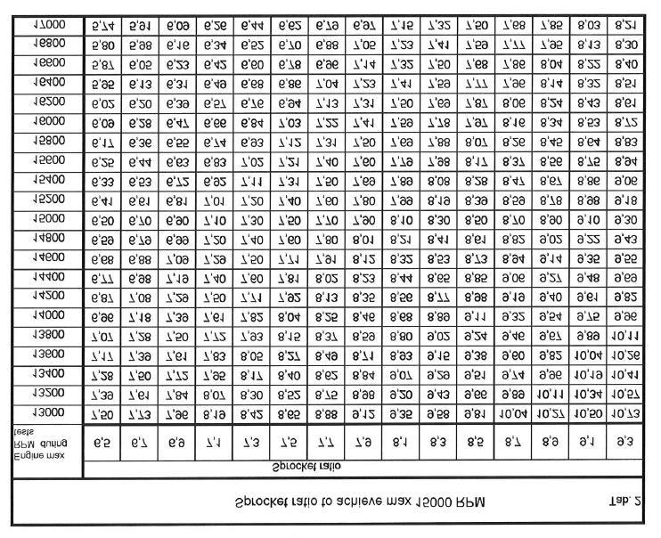
31 Tab.1 Sprocket ratio Teeth n - Engine sprocket Sprocket ratio Teeth n - Engine sprocket Teeth n - axle sprocket Teeth n - axle sprocket ,20 6, ,30 7, ,30 6, ,40 7, ,40 6, ,50 7, ,50 6, ,60 7, ,60 6, ,70 7, ,70 7, ,80 8, ,80 7, ,90 8, ,90 7, ,00 8, ,00 7, ,10 8, ,10 7, ,20 8, ,20 7,45 For the operation limit of RPM the following table (Tab.2) has been prepared. SUGGESTION: During the track tests we recommend use of a tachometer recording the max obtained engine RPM. Use sparkplug caps with a resistance of 5KÙ to avoid eventual interferences between the engine ignition and the tachometer and/or telemetry. The following example should clarify the procedure for the optimization of the sprocket. Assume to use the engine with Z=10 teeth engine sprocket and that during the preliminary track tests a Z=72 teeth axle sprocket has been used. From table 1 with Z=10 as engine sprocket and Z=72 on the axle sprocket, a ratio of 7.20 is found. Make a few laps on the track and, let us assume that you read max engine RPM. From the table 2 to achieve a max RPM of RPM (operating limit for the Leopard engine) a sprocket ratio from 7.61 and 7.82 should be used (having used, during the tests, a sprocket ratio of 7.2 and having achieved RPM max.). From table.1, with these values, a sprocket ratio of 10:76 / 10:78 should be used or, having a Z=11 on the engine sprocket, a ratio 11:85 should be used. 29
32 30

33 15- SCHEDULED MAINTENANCE Following some simple maintenance standards will allow the engine to perform more reliably and have a longer life. SCHEDULE COMPONENTS ACTIONS AND COMMENTS Before using Exhaust flexible Check status Exhaust springs Check status Exhaust strap Check status Exhaust muffler Check status and fixing Engine sprocket Check wear Check alignment with axle sprocket Engine chain Check status, tensioning, and oil chain Battery Check status and charge Cables and connectors Check status and connections Grounding of engine and Power Check status and connections Pack Engine mount and clamps Check torques After use Battery Disconnect Chain Check status and oil chain Engine External cleaning Every 5-10 hours Bendix assembly Remove cover (see fig.) and clean internally Exhaust muffler Remove muffler end, clean Inlet silencer Open, clean Engine head Open, clean Engine clutch Open, check status of parts every 20 hours Piston and Con-rod assembly Check and replace worn parts Crankshaft Check and replace worn parts Ball bearings Check and replace worn parts 31
34 16- TROUBLESHOOTING Below are some common faults, their probable causes and suggested remedy: FAULTS PROBABLE CAUSE REMEDY Starter will not crank when Bad connections on starter cables. Check and tighten pushing the start button. Bad grounding Check connections and tighten Damaged cables Replace Battery connection loose Check and tighten Starter cranks but engine won t start Engine starts when the start bottom is pressed but it stops when bottom is released. The starter cranks after having released the start button Battery discharged Starter failure Power Pack internal failure (fuse starter relay, connectors Bad cable connections Bad H.T. coil connection or coil failure Bad H.T. coil grounding Power pack internal cable bad connection Wet spark plug Malfunction on induction system Bad cable connections Bad connections on Power-Pack internal cables Bad carburetor adjustment (I screw) Battery discharged (starter relay does not disconnect). Recharge battery Overhaul starter Apply to Authorized Service Center Check connectors (3 and 4 ways) Check/Replace Check and tighten (2 grounds) Apply to Authorized Service center Replace Check status and connections on fuel pipe Replace gaskets and membranes on carburetor Check reed petals. Replace if necessary. Check stator connector (4 ways). Apply to Authorized Service Center Check carburetor adjustment (see par. 5) Disconnect the positive terminal on battery and charge battery. Rough idle Bad carburetor adjustment Check carburetor adjustment (see (L Screw) par. 5) Drop in engine performance Bad compression Check piston Bad carburetor adjustment Check carburetor adjustment (see par. 5) Insufficient gas flow Check gasoline flow lines Dirty inlet silencer Check and clean Burning smell, smoke Overheating of clutch Check clutch (Par. 11) Clutch engages at too high Excessive wear of friction material Check clutch (Par. 11) RPMs Exhaust too noisy Flexible damaged Check and replace if necessary Springs damaged or lost Insulating strap damaged or lost. Damaged exhaust header 32
35 17- ENGINE PRESERVATION When engine is to remain unoperative for a long period it must be preserved as follows: Disconnect the battery and charge it periodically (see Par. 12) Disconnect carburetor and clean it Seal with tape the engine inlet and exhaust The external of the engine must be cleaned. Spray with protective oil the steel parts subject to oxidation. Keep the engine in a dry ambient. 33
36 34
37 35

38 WIRING DIAGRAM Assembly Instructions & User Manual ª 2001 by IAME joint stock Comp. 1 st Edition, November 2000 All rights reserved. Any reprinting or Unauthorized use without the written Permission of IAME joint stock Comp. Is expressly prohibited 36
ASSEMBLY INSTRUCTIONS
 C 125cc LEOPARD TaG engine 2003 ASSEMBLY INSTRUCTIONS and USER MANUAL 18/10/02 mod. INDEX GENERAL DESCRIPTION OF THE "LEOPARD" ENGINE CHARACTERISTICS OF THE "LEOPARD" ENGINE OPERATIONAL LIMITS 1- Contents
125cc RL - TaG ASSEMBLY INSTRUCTIONS & USER MANUAL
 125cc RL - TaG ASSEMBLY INSTRUCTIONS & USER MANUAL - 1 - MAN-043E MAN-043E ENG - ENG I N D E X PAGE Section 1 DESCRIPTION OF THE IAME X30 125cc RL - TaG ENGINE 01 1.1. Main features 01 1.2. Characteristics
INSTALLATION MANUAL. REEDJET 100cc -TaG MAN-72/C - USA
 INSTALLATION MANUAL REEDJET 100cc -TaG MAN-72/C - USA I N D E X PAGE General description of engine 01 Engine features / Operational limits 02 Contents of packaging 02 Accessories 03 Engine identification
X30 125cc Spec. EU ASSEMBLY INSTRUCTIONS AND USER MANUAL MAN-089
 X30 125cc Spec. EU ASSEMBLY INSTRUCTIONS AND USER MANUAL MAN-089 FEEDING Fuel mixture 98 RON and oil 5% (20:1) minimum. Engine oil CIK homologated. Our experience dictates use of oils, such as: - WLADOIL
BASIC MANUAL X30 125CC MAN-80
 BASIC MANUAL X30 125CC FEEDING Fuel mixture 98 RON and oil 5% (20:1) minimum. Engine oil CIK homologated. Our experience dictates use of oils, such as: - WLADOIL K 2T; - ELF HTX 909; - ELF HTX 976; - LEXOIL
REEDJET AUS 100cc TaG
 REEDJET AUS 100cc TaG INSTALLATION MANUAL 01/11/04 MAN-033 GENERAL DESCRIPTION OF ENGINE This engine of the "TaG" series (Touch and Go) has been expressly designed and developed to power Karts for hobby
REEDSTER 125cc. F1 - F2 - F3 - F4 Versions ASSEMBLY INSTRUCTIONS & USER MANUAL
 REEDSTER 125cc F1 - F2 - F3 - F4 Versions ASSEMBLY INSTRUCTIONS & USER MANUAL 21/01/09 2 INDEX N Page Section 1 DESCRIPTION OF THE Parilla REEDSTER 125cc ENGINE 1 2 3 4 5 1.1. Main features 1.2. Engine
MANUAL INDEX. Page 1. LEOPARD 125cc ENGINE DISASSEMBLY CRANKSHAFT DISASSEMBLY/ ASSEMBLY CRANKSHAFT DISASSEMBLY 8
 MANUAL INDEX Page 1. LEOPARD 125cc ENGINE DISASSEMBLY 1 2. - CRANKSHAFT DISASSEMBLY/ ASSEMBLY 8 2.1- CRANKSHAFT DISASSEMBLY 8 2.2- CRANKSHAFT ASSEMBLY 10 3. LEOPARD 125cc ASSEMBLY 13 4. - CHECK CYLINDER
OVERHAUL MANUAL 28/09/05 mod. A 1 MAN-044 ING
 OVERHAUL MANUAL 28/09/05 mod. A 1 INDEX Page 1. - PARILLA X30 125cc RL TaG ENGINE DISASSEMBY 1 2. - CRANKSHAFT DISASSEMBLY/ ASSEMBLY 10 2.1- CRANKSHAFT DISASSEMBLY 10 2.2- CRANKSHAFT ASSEMBLY 12 3. - PARILLA
REEDSTER 125cc. versions: F1 - F2 - F3 - F4 OVERHAULING MANUAL
 REEDSTER 125cc versions: F1 - F2 - F3 - F4 OVERHAULING MANUAL 07/11/07 21/01/2009 1 INDEX Page 1. - REEDSTER 125cc ENGINE DISASSEMBLY 1 2. - CRANKSHAFT DISASSEMBLY / ASSEMBLY 13 2.1 - CRANKSHAFT DISASSEMBLY
BASIC MANUAL X30 SUPER 175CC MAN-78
 BASIC MANUAL X30 SUPER 175CC FEEDING Fuel mixture 98 RON and 4,5% oil (22:1 - CIK homologated) Our experience dictates use of oils, such as: - WLADOIL K 2T; - ELF HTX 909; - ELF HTX 976; - SHELL ADVANCE
Drill pattern for engine mount
 2006 A CONTENTS OF KIT Each HPV100 engine is delivered with the following components: Quantity Description 1 Sparkplug cap 1 Sparkplug (NGK BR10EG) 1 Exhaust System 2 Exhaust springs 1 Carburetion phenolic
BASIC INSTRUCTIONS SHIFTER KZ1 / KZ2 e X30 SHIFTER-TaG
 BASIC INSTRUCTIONS SHIFTER KZ1 / KZ2 e X30 SHIFTER-TaG FEEDING: by fuel mixture 98NO (min. 95NO) and 4% oil (CIK homologated). ATTENTION: the engine is supplied without oil in the gearbox. GEARBOX OIL
WORKSHOP MANUAL. Chainsaw GS35 GS350 MT350 MT3500
 WORKSHOP MANUAL Chainsaw GS35 GS350 MT350 MT3500 General failures analysis Suggested tools I. Emak tool kit II. Compression tester: to check thermal group III. Electronic tachometer: for 2 and 4 stroke
INDEX TECHNICAL SPECIFICATIONS 2 SPECIAL TOOLS 3-4 PERIODIC MAINTENANCE 5 LUBRICANTS 6 TROUBLESHOOTING 7-14 TIGHTENING TORQUE TABLE 15
 INDEX TECHNICAL SPECIFICATIONS 2 SPECIAL TOOLS 3-4 PERIODIC MAINTENANCE 5 LUBRICANTS 6 TROUBLESHOOTING 7-14 TIGHTENING TORQUE TABLE 15 ENGINE DISASSEMBLY 16-24 ENGINE REASSEMBLY 25-37 SPECIAL 3-SHOE CLUTCH
WORKSHOP MANUAL. 63,4 cm³ chainsaws
 WORKSHOP MANUAL General failures analysis Suggested tools I. Emak tool kit II. Compression tester: to check thermal group III. Electronic tachometer: for 2 and 4 stroke engines, measurement range from
ENGINE. IAME SPA IAME KA cc REEDJET AUS TaG 6 Years 28
 ENGINE Manufacturer Make Model Validity of the homologation Number of pages IAME SPA IAME KA 100-100cc REEDJET AUS TaG 6 Years 28 This Homologation Form reproduces descriptions, illustrations and dimensions
X30 CHALLENGE INTERNATIONAL TECHNICAL REGULATIONS 2017 PART 2 ENGINES
 X30 CHALLENGE INTERNATIONAL TECHNICAL REGULATIONS 2017 PART 2 ENGINES X30 CHALLENGE INTERNATIONAL TECHNICAL REGULATIONS 2017 - PART 2: ENGINES ARTICLE 1 - ENGINE IAME X30 125cc RL TaG - X30 SENIOR & X30
100cc REEDJET USA TaG
 100cc REEDJET USA TaG FEATURES Cylinder Volume 100 cm³ max Bore 48.20 mm Max. theoretical bore 48.53 mm Stroke 54.05 mm max Cooling system Air Inlet system Reed valve Number of carbs 1 Tillotson Carburettor
Ciscomotors C-Max All types of models
 Ciscomotors C-Max All types of models SiMPLIFIED MAINTENANCE MANUAL All information in this publication is based on latest specification s product available at the time of approval for printing. CISCOMOTORS
Operation and Maintenance Instructions for the RAPTOR 178
 WWW.SKYTOY.COM Operation and Maintenance Instructions for the RAPTOR 178 See www.skytoy.com for updates and service bulletins. 2/1/2011 1. Parts Schematic:... 3 2. Muffler Assembly Diagram:... 4 3. Muffler
334A or 334AB. Number of piston rings 1 Number of exhaust ports 2. Big end conr. Ball-bearing diam. 18X24X15 Combustion chamber shape Spherical
 125cc LEOPARD FEATURES Cylinder volume 123.67 cc Bore 54 mm Max. theoretical bore 54.28mm Stroke 54mm Cooling system Water Inlet system Reed valve Number of carbs 1 Tillotson HL Carb. 334A or 334AB Cylinder/crankcase
Typical Install Instructions
 Typical Install Instructions Read & understand all steps of these instructions before beginning this installation. WEBER Conversion Kit, VW T-1/2, up to 1835cc 32 / 36 DFEV Weber Carburetor These instructions
SECTION 4 - FUEL SYSTEMS AND CARBURETION
 SECTION - FUEL SYSTEMS AND CARBURETION FUEL SYSTEMS - - - - - - - - - - - - - - - - - - - - - - - - - - - - - - - - - - - - - - - - - - - - - - - - - - - - - - - - - - - - - -62 FUEL PUMP - - - - - - -
Repair Manual 11/99 PS-34. Page 1
 Repair Manual /99 PS-4 Page Table of contents Index Technical Data page Special tools 4 Repair instructions, general 0 Chain brake 6 0 Centrifugal clutch 8 0 Oil pump 9-04 Ignition system - 0 Starting
McCULLOCH. Stroke. 30 mm (1.2 in.) 30 mm (1.2 in.) 30 mm (1.2 in.) 30 mm (1.2 in.)
 30 mm (1.2 in.) 30 mm (1.2 in.) 30 mm (1.2 in.)") SERVICE MANUAL Model Eager Beaver 2010, Mac 3210 Silver Eagle 2012 Eager Beaver 2014, Mac 3214, Silver Eagle 2014 Eager Beaver 2016, Mac 3216, Silver Eagle 2016 Bore Stroke DispL (2.1 cu. in.) (2.1CU.
SERVICE MANUAL Model Eager Beaver 2010, Mac 3210 Silver Eagle 2012 Eager Beaver 2014, Mac 3214, Silver Eagle 2014 Eager Beaver 2016, Mac 3216, Silver Eagle 2016 Bore Stroke DispL (2.1 cu. in.) (2.1CU.
MINI Engine Manual. Introduction. OTK KART GROUP s.r.l. Via dei Soprini Prevalle (Brescia) IT
 IT") Introduction Thank you for purchasing MINI Vortex engines. This manual contains information to help you to get the best results from your new engine. Furthermore, it will explain you how to operate your
Introduction Thank you for purchasing MINI Vortex engines. This manual contains information to help you to get the best results from your new engine. Furthermore, it will explain you how to operate your
IAME X30-16,000 RPM 2014 CATALOG
 IAME - 16,000 RPM 2014 CATALOG HEAD AND CYLINDER 001 125040-C CYL. HEAD 229.68 002 10350 HEAD NUT 3.56 003 10635 HEAD NUT WASHER H=3mm 1.81 004 B-25840 TEMP. GAUGE PLUG 4.16 005 B-25845 TEMP. GAUGE PLUG
Racing Performance Catalog & Reference Guide Model/Type:
 Version 4/08 Racing Performance Catalog & Reference Guide Model/Type: 124435 8105-01 Table of Contents SAFETY... 1 WORLD FORMULA General Specs...3 Special Tools...3 Torque Specs...3 Racing Specifics...3
TECHNICAL DATA. COMPRESSION RATUI 9,5/1 WEIGHT ready to fly CONSUMPTION at 5400RPM 5,6litres/h POWER at 6200RPM
 VICTOR 1 SUPER This handbook aims to bring to the attention of key technical, functional and maintenance of your motor VICTOR 1. Read carefully the following pages, will be synonymous with safety, reliability
rev 1_09/20/2017 PS-35C EA3500SR
 C 1 Tank, Handle 5 7 6 8 17 9 1 2 10 11 12 13 18 19 20 3 21 4 22 23 14 16 2 1 Tank, Handle 1 1 168507-3 TANK CAP COMPLETE 1 1 INC. 2 1 2 213080-9 O RING 29.5 1 1 1 3 163447-0 GASOLINE FILTER 1 1 1 4 195757-7
IAME LEOPARD (2008 & OLDER)
") IAME (2008 & OLDER) 2014 CATALOG HEAD AND CYLINDER 001 A-125041 CYL. HEAD /K25 233.83 002 10350 HEAD NUT 3.56 003 10635 HEAD NUT WASHER H=3mm 1.81 004 B-25840 TEMP. GAUGE PLUG 4.16 005 B-25845 TEMP. GAUGE
IAME (2008 & OLDER) 2014 CATALOG HEAD AND CYLINDER 001 A-125041 CYL. HEAD /K25 233.83 002 10350 HEAD NUT 3.56 003 10635 HEAD NUT WASHER H=3mm 1.81 004 B-25840 TEMP. GAUGE PLUG 4.16 005 B-25845 TEMP. GAUGE
ENGINE. Manufacturer IAMEs.p.a. Category. Homologation Period. Pages 16. Model, Type SIGNATURE AND STAMP OF AKA SIGNATURE AND STAMP OF APPLICANT
 1 ENGINE Manufacturer IAMEs.p.a. Category Make Model, Type PARILLA Leopard X30 125cc RL - TaG - AUS Homologation Period Pages 16 This homologation sheet reproduces description, illustrations and dimensions
IAME X30-16,000 RPM 2018 CATALOG
 IAME - 16,000 RPM 2018 CATALOG HEAD AND CYLINDER 1 125040-C CYL. HEAD 229.68 002 10350 HEAD NUT 3.56 10352 CYLINDER HEAD NUT W/TECH WIRE HOLE 8.35 003 10635 HEAD NUT WASHER H=3mm 1.81 004 B-25840 TEMP.
Super 1050 Chain Saw UT Page 1 of 16 Carburetor Chamber
 Super 1050 Chain Saw UT-10139 Page 1 of 16 Carburetor Chamber Super 1050 Chain Saw UT-10139 Page 2 of 16 Carburetor Chamber 1 58319A 1 RING- Retaining 2 592301 1 COVER- Air filter 3 A70326 1 NUT- Cover
Illustration Engine. PTX 2710 (EPA 3) Pole pruner. 3/27/2017 Page Copyright COMET USA, INC.
 Pole pruner. 3/27/2017 Page Copyright COMET USA, INC.") Documents Engine Starter assy and clutch Tank and air filter Adjustable telescopic pole Pruner Carburetor WT-1150 Accessories 3/27/2017 Page 1-16 Illustration Engine 3/27/2017 Page 2-16 Illustration Engine
Documents Engine Starter assy and clutch Tank and air filter Adjustable telescopic pole Pruner Carburetor WT-1150 Accessories 3/27/2017 Page 1-16 Illustration Engine 3/27/2017 Page 2-16 Illustration Engine
WEBER CARBURETOR TROUBLESHOOTING GUIDE
 This guide is to help pinpoint problems by diagnosing engine symptoms associated with specific vehicle operating conditions. The chart will guide you step by step to help correct these problems. For successful
Reproduction. Not for. Briggsracing.com. CORPORATION Briggs & Stratton Corporation MS /08
 Briggsracing.com MS-5702-4/08 BRIGGS&STRATTON CORPORATION Post office box 702 Milwaukee, WI 53201 USA 414 259 5333 2008 Briggs & Stratton Corporation Version 4/08 Racing Performance Catalog & Reference
Manufacturer Address Engine # IAME S.p.A. Via Lisbona, ZINGONIA (ITALY) X30 125cc RL-C TaG. Number of pages 22 PICTURE OF ENGINE
 X30 125cc RL-C TaG. Number of pages 22 PICTURE OF ENGINE") Manufacturer Address Engine # IAME S.p.A. Via Lisbona, 15 24040 ZINGONIA (ITALY) TAG RACING INTERNATIONAL TM Manufacturer IAME S.P.A. - ZINGONIA (I) Make PARILLA Model X30 125cc RL-C TaG Inlet type REED
Manufacturer Address Engine # IAME S.p.A. Via Lisbona, 15 24040 ZINGONIA (ITALY) TAG RACING INTERNATIONAL TM Manufacturer IAME S.P.A. - ZINGONIA (I) Make PARILLA Model X30 125cc RL-C TaG Inlet type REED
SERVICE DATA CHAIN SAW ECHO: CS-500ES STAGE MODEL. (Serial number : and after) CONTENTS INTRODUCTION
 CONTENTS INTRODUCTION") 01-50D-01 1 0 SERVICE DATA CHAIN SAW ECHO: STAGE MODEL (Serial number : 37000001 and after) INTRODUCTION We are constantly working on technical improvement of our products. For this reason, technical data,
01-50D-01 1 0 SERVICE DATA CHAIN SAW ECHO: STAGE MODEL (Serial number : 37000001 and after) INTRODUCTION We are constantly working on technical improvement of our products. For this reason, technical data,
Engine Does Not Start or Is Hard to Start Cause of Trouble. 1. Open the drain screw, and check Fuel not supplied (1) Fuel tank empty
 Fuel tank empty") 20. Engine Does Not Start or Is Hard to Start 20-1 Engine Output Insufficient 20-2 Poor Performance at Low Speed and Idling 20-3 Poor Performance at High Speed 20-3 Unsatisfactory Operation 20-4 Fuel Gauge
20. Engine Does Not Start or Is Hard to Start 20-1 Engine Output Insufficient 20-2 Poor Performance at Low Speed and Idling 20-3 Poor Performance at High Speed 20-3 Unsatisfactory Operation 20-4 Fuel Gauge
45.06 Fuel Refer Chapter 22 Fuel, as run, to comply with tests under chapter 22.01
 CHAPTER 45 PARILLA LEOPARD 125cc and PARILLA LEOPARD X30 125cc Preamble It is expected that this class will continue to evolve during its early life and the promoters of the class reserve the right to
Tillotson Tc3A Carburator
 Tillotson Tc3A Carburator 176 FUEL SYSTEMS - 5B-11 CENTER BOWL TYPE CARBURETOR Removal 1. Remove front cowl cover and wrap-around cowl. 2. Remove swivel link from lower carburetor. (Figure 2) 3. Loosen
00-36A-04 CS-350T, CS-350TES, CS-350WES 1
 00-36A-04,, 1 0 INTRODUCTION We are constantly working on technical improvement of our products. For this reason, technical data, equipment and design are subject to change without notice. All specifications,
CARBURETION. Carburetor Identification. Models , , , , , , , , , , ,
 Carburetor Identification Models 110400, 110600, 111400, 111600, 113400, 120400, 120600, 121400, 121600, 122600, 123400, 123600 Models 28S700, 311700 Service Carburetor Briggs & Stratton/Walbro LMS Models
IAME Gazelle 60cc. Italian Motors Ltd. Phone:
 1 A-60040 Cylinder HEAD 1 A-60041 Cylinder HEAD 2.00352 M8 Head NUT 3.00303 M8 Head nut WASHER 11 EBP-85045 4/10 Cylinder GASKET 11 EBP-85046 2/10 Cylinder GASKET 13A A-60030 Complete CYLINDER 13A A-60031
9.1 Technical Specification (within the engine seal) for ROTAX kart engines 125 Junior MAX (15 kw) 125 MAX (21 kw). 125 Junior MAX 125 MAX
 for ROTAX kart engines 125 Junior MAX (15 kw) 125 MAX (21 kw). 125 Junior MAX 125 MAX") 9.1 Technical Specification (within the engine seal) for ROTAX kart engines 125 Junior MAX (15 kw) 125 MAX (21 kw). Squish gap 1.1 1.2 Combustion chamber insert 2.1 2.2 125 Junior MAX 125 MAX 1,20 mm -
9.1 Technical Specification (within the engine seal) for ROTAX kart engines 125 Junior MAX (15 kw) 125 MAX (21 kw). Squish gap 1.1 1.2 Combustion chamber insert 2.1 2.2 125 Junior MAX 125 MAX 1,20 mm -
PARILLA LEOPARD RL 125 TECHNICAL SPECIFICATIONS
 PARILLA LEOPARD RL 125 VERSION 4 / 2012 UPDATED September 6 th, 2012 DOCUMENT UPDATE SCHEDULE It is certified that the updates listed below have been approved by the Australian Karting Association and
SERVICE DATA CHAIN SAW CS-450. (Serial number : and after) CONTENTS INTRODUCTION. Reference No B-01 REVISED: ISSUED:
 CONTENTS INTRODUCTION. Reference No B-01 REVISED: ISSUED:") 01-45B-01 1 0 SERVICE DATA CHAIN SAW (Serial number : 36000001 and after) INTRODUCTION We are constantly working on technical improvement of our products. For this reason, technical data, equipment and
01-45B-01 1 0 SERVICE DATA CHAIN SAW (Serial number : 36000001 and after) INTRODUCTION We are constantly working on technical improvement of our products. For this reason, technical data, equipment and
I. TWO-STROKE MECHANICAL EN- GINE PARTS
 I. TWO-STROKE MECHANICAL EN- GINE PARTS 1. UNIBLOCK ENGINES (AV520-600-750-125) a) INTRODUCTION Fig. 1 shows the short block. Fig. 2 shows an exploded view of the engine. As may be seen the momoblock is
CARTER DOWNDRAFT CARBURETOR Terraplane All Models. Technical Information
 CARTER DOWNDRAFT CARBURETOR 1934 Terraplane All Models Technical Information . Carter W-1 Downdraft Carburetors 1934 Terraplane Challenger, Model KS NOTE: Terraplane Models. Carburetor fitted with Anti-
TILLOTSON LTD., CLASH INDUSTRIAL ESTATE, TRALEE, CO. KERRY, IRELAND PHONE: FAX:
 TILLOTSON LTD., CLASH INDUSTRIAL ESTATE, TRALEE, CO. KERRY, IRELAND PHONE: +353 66 7121911 FAX: +353 66 7124503 e-mail: sales@tillotson.ie HR SERIES SERVICE MANUAL INTRODUCTION Tillotson has developed
ENGINE 6G74 3.5L-SOHC-24 VALVE
 11A ENGINE General Information/Service Specifications ENGINE 6G74 3.5L-SOHC-24 VALVE GENERAL INFORMATION Items Specifications Type V-type, Over Head Camshaft Number of cylinders 6 Bore mm 93.0 Stroke mm
HORSTMAN GREASED LIGHTNING CLUTCH
 HORSTMAN GREASED LIGHTNING CLUTCH Horstman s Greased Lightning (GL) clutch is designed for ultra high performance, and requires expert setup and a serious commitment to maintenance. Warning!!! 1. Clutch
STIH) Technical Information New cut-off machine STIHL TS 700 Series 4224
 Technical Information New cut-off machine STIHL TS 700 Series 4224") STIH) Technical Information 52.2004 New cut-off machine STIHL TS 700 Series 4224 Contents 1. Technical description 2. Technical data 3. Accessories 4. Service accessories 5. Repairs 6. Spare parts englisch
STIH) Technical Information 52.2004 New cut-off machine STIHL TS 700 Series 4224 Contents 1. Technical description 2. Technical data 3. Accessories 4. Service accessories 5. Repairs 6. Spare parts englisch
Note: Registration does not imply or guarantee use in a class
 1 Note: Registration does not imply or guarantee use in a class or classes. Application for use in a class or classes must be applied for after Homologation and Registration approvals ENGINE Manufacturer
HIRTH 3203 Carburated - 65 hp
 HIRTH 3203 Carburated - 65 hp 2706-65Hp engine shown with fan cooling HIRTH s most popular engine. The 3203 produces more horsepower and torque per pound than any other engine in its power class. Hirth
MODELS 3100,3130,3160, 1300, 1330,1360 EXHAUST SYSTEM
 MODELS 3100,3130,3160, 1300, 1330,1360 EXHAUST SYSTEM WALBRO CARBURETOR "WA" SERIES MUFFLER REMOVAL CARBURETOR REMOVAL The muffler assembly should beremoved periodically to inspect for excessive carbon
SERVICE DATA CHAIN SAW ECHO: CS-352ES STAGE MODEL. (Serial number : and after) CONTENTS INTRODUCTION
 CONTENTS INTRODUCTION") 01-34D-01 1 0 SERVICE DATA CHAIN SAW ECHO: STAGE MODEL (Serial number : 37000001 and after) INTRODUCTION We are constantly working on technical improvement of our products. For this reason, technical data,
01-34D-01 1 0 SERVICE DATA CHAIN SAW ECHO: STAGE MODEL (Serial number : 37000001 and after) INTRODUCTION We are constantly working on technical improvement of our products. For this reason, technical data,
WORKSHOP MANUAL TECHNICAL NETWORK LEADERSHIP WORKSHOP MANUAL 125 CC/150 CC 4-STROKE ENGINE
 WORKSHOP MANUAL TECHNICAL NETWORK LEADERSHIP WORKSHOP MANUAL - 5 CC/50 CC 4-STROKE ENGINE Workshop manual Technical network leadership TABLE OF CONTENTS TABLE OF CONTENTS TABLE OF CONTENTS... CHARACTERISTICS...
SECTION 4 - FUEL/LUBRICATION/COOLING
 For Arctic Cat Discount Parts Call 606-678-9623 or 606-561-4983 SECTION 4 - FUEL/LUBRICATION/COOLING 4 TABLE OF CONTENTS Carburetor Specifications... 4-2 Carburetor Schematic... 4-2 Carburetor... 4-3 Cleaning
PARILLA - X rpm
 PARILLA - X30 16.000 rpm stampato il 03/02/12 Catalogo 2012 HEAD AND CYLINDER 001 X30125040-C CYL. HEAD X30 002 10350 HEAD NUT 003 10635 HEAD NUT WASHER H=3mm 004 B-25840 TEMP. GAUGE PLUG 005 B-25845 TEMP.
STARTING/CHARGING SYSTEMS Brought to you by Eris Studios NOT FOR RESALE
 STARTING/CHARGING SYSTEMS General Description 1. General Description A: SPECIFICATION Vehicle model Starter Generator Item Specification Type Reduction type Model 428000-5760 Manufacturer DENSO Voltage
613GC Key A Parts Starter & Ignition Assembly
 613GC Key A Parts Starter & Ignition Assembly 73866 Screw (same as B26) A01 505514 Starter Rope Handle A02 73904 Starter Rope A03 73909 Starter Coil Spring & Housing A04 71451 Starter Case Plate A05 73910
SERVICE DATA CHAIN SAW ECHO: CS-280WES STAGE MODEL. (Serial number : and after) CONTENTS INTRODUCTION. Reference No B-00 ISSUED:
 CONTENTS INTRODUCTION. Reference No B-00 ISSUED:") 00-27B-00 1 0 SERVICE DATA CHAIN SAW ECHO: STAGE MODEL (Serial number : 37000001 and after) INTRODUCTION We are constantly working on technical improvement of our products. For this reason, technical data,
00-27B-00 1 0 SERVICE DATA CHAIN SAW ECHO: STAGE MODEL (Serial number : 37000001 and after) INTRODUCTION We are constantly working on technical improvement of our products. For this reason, technical data,
INSIDE YOUR HOLLEY CARBURETOR FUEL INLET SYSTEM
 INSIDE YOUR HOLLEY CARBURETOR The carburetor is quite simply a fuel metering device that operates under the logical and straightforward laws of physics. It has evolved over the years from a very simple
WARNING: ALWAYS relieve fuel pressure before disconnecting any fuel related component. DO NOT allow fuel to contact engine or electrical components.
 4.0L V8 - VINS [K,U] Selected Block 1990 Lexus LS 400 For Lextreme Powertrain 2020 S. Hacienda Blvd. # D Hacienda Heights California 91745 Copyright 1998 Mitchell Repair Information Company, LLC Friday,
SALES DIVISION NETWORK TECHNICAL INFORMATION WORKSHOP MANUAL MOTOR ENGINE
 SALES DIVISION NETWORK TECHNICAL INFORMATION WORKSHOP MANUAL MOTOR ENGINE CONTENTS CHARACTERISTICS... 5 Engine markings... 5 TIGHTENING TORQUES... 5 SPECIAL TOOLS... 6 IDENTIFICATION... 7 Differences between
TILLOTSON LTD., CLASH INDUSTRIAL ESTATE, TRALEE, CO. KERRY, IRELAND PHONE: FAX:
 TILLOTSON LTD., CLASH INDUSTRIAL ESTATE, TRALEE, CO. KERRY, IRELAND PHONE: +353 66 7121911 FAX: +353 66 7124503 e-mail: sales@tillotson.ie SERIES SERVICE MANUAL INTRODUCTION The gasoline engine industry
Operating instructions
 Operating instructions MVVS 50 IRS No: 3005L/3005S Before using the engine, please read these instructions carefully. Congratulations on choosing the MVVS 50 gas engine. The MVVS 50 has been designed and
ENGINE CONTENTS ENGINE REMOVAL AND REINSTALLATION 3-1 ENGINE REMOVAL 3-1 ENGINE REINSTALLATION 3-5 ENGINE DISASSEMBLY 3-7 STARTER MOTER 3-7
 ENGINE CONTENTS ENGINE REMOVAL AND REINSTALLATION 3- ENGINE REMOVAL 3- ENGINE REINSTALLATION 3-5 ENGINE DISASSEMBLY 3-7 3 STARTER MOTER 3-7 CYLINDER HEAD COVER 3-8 PISTON 3- MAGNETO COVER 3-3 MAGNETO ROTOR
Operating instructions
 Operating instructions MVVS 116 NP No: 3010NP Before using the engine, please read these instructions carefully. Congratulations on choosing the gas engine MVVS 116cc. MVVS 116cc has been designed and
1.6L 4-CYL - VIN [E]
![1.6L 4-CYL - VIN [E]](/thumbs/81/84172348.jpg "1.6L 4-CYL - VIN [E]") 1.6L 4-CYL - VIN [E] 1993 Nissan Sentra 1993 NISSAN ENGINES 1.6L 4-Cylinder NX, Sentra * PLEASE READ THIS FIRST * NOTE: For engine repair procedures not covered in this article, see ENGINE OVERHAUL PROCEDURES
1.6L 4-CYL - VIN [E] 1993 Nissan Sentra 1993 NISSAN ENGINES 1.6L 4-Cylinder NX, Sentra * PLEASE READ THIS FIRST * NOTE: For engine repair procedures not covered in this article, see ENGINE OVERHAUL PROCEDURES
K&T Saw Shop or MC 92 04/77 to 07/77 IPL Page 1 of 9 Accessories
 15-400165 MC 92 04/77 to 07/77 IPL 91077 Page 1 of 9 Accessories 15-400165 MC 92 04/77 to 07/77 IPL 91077 Page 2 of 9 Accessories 68899 Piston Assy, 2.170 68897 Piston Assy, 2.175 87940 Piston Assy, 2.185
FUEL SYSTEM. Table of Contents. Specifications. Section 3A Fuel Delivery System. Models 6/8/9.9/10/15 CARBURETOR SPECIFICATIONS
 FUEL SYSTEM Section 3A Fuel Delivery System Table of Contents Specifications............................. 3A-1 WMC Carburetor Specifications............. 3A-2 WMC Carburetor Specifications.............
KING CANADA 950W PORTABLE GENERATOR MODEL: KCG-951G INSTRUCTION MANUAL COPYRIGHT 2011 ALL RIGHTS RESERVED BY KING CANADA TOOLS INC.
 KING CANADA 950W PORTABLE GENERATOR MODEL: KCG-951G INSTRUCTION MANUAL COPYRIGHT 2011 ALL RIGHTS RESERVED BY KING CANADA TOOLS INC. WARRANTY & SERVICE INFORMATION 1-YEAR LIMITED WARRANTY FOR THIS 950W
Replacement Parts & Accessories Price List
 Replacement Parts & Accessories Price List 680GC Petrol Concrete Saw Serial numbers starting with 967 & 977 Effective January 1, 2011 TABLE OF CONTENTS 680GC Petrol Concrete Saw ITEM DESCRIPTION KEY PAGE
February 26, ch.12.notebook. Ch. 12. Preventative Maintenance and Troubleshooting. Feb 23 5:03 PM
 Ch. 12 Preventative Maintenance and Troubleshooting Feb 23 5:03 PM 1 Why PM? preventive maintenance certain maintenance tasks must be performed regularly to keep an engine working properly helps premature
440 & 443 Skid Steer
 Bobcat 440 & 443 Skid Steer THIS IS A MANUAL PRODUCED BY JENSALES INC. WITHOUT THE AUTHORIZATION OF BOBCAT OR IT S SUCCESSORS. BOBCAT AND IT S SUCCESSORS ARE NOT RESPONSIBLE FOR THE QUALITY OR ACCURACY
Not for Reproduction ADVANCE PRODUCT SERVICE INFORMATION APSI NO: 101 DATE: AUGUST SERIES UTILITY ENGINE 130G00 OHV HORIZONTAL SHAFT
 ADVANCE PRODUCT SERVICE INFORMATION APSI NO: 101 DATE: AUGUST 2014 SUBJECT: MODELS: 950 SERIES UTILITY ENGINE 130G00 OHV HORIZONTAL SHAFT This APSI provides basic servicing information in advance of the
2007 HOP-UP INFORMATION. Foreword
 2007 HOP-UP INFORMTION Foreword This manual contains the hop-up information for RM series of European specification and is intended to allow the standard model to achieve its maximum performance potential.
Replacement Parts & Accessories Price List
 Replacement Parts & Accessories Price List 613GC Gas Concrete Saw Effective January 1, 2010 SERVICE ITEMS 613GC Gas Concrete Saw Above 71700 Gas Saw Service Tool Kit, includes all items shown above $668.00
1.8L & 2.2L 4-CYL Article Text 1998 Subaru Impreza
 1.8L & 2.2L 4-CYL Article Text 1998 Subaru Impreza ARTICLE BEGINNING 1995-98 ENGINES Subaru - 1.8L & 2.2L 4-Cylinder 1995-97: Impreza (1.8L) 1995-98: Impreza (2.2L), Legacy (2.2L) * PLEASE READ THIS FIRST
695XL SERVICE MANUAL
 695XL SERVICE MANUAL TABLE OF CONTENTS SECTION SECTION TITLE PAGE NUMBER SERVICE MANUAL USE... 3 1 TOOLS... 4 2 POWER CUTTER SPECIFICATIONS... 5 3 SERIAL NUMBER LOCATION... 6 4 SPARE PARTS DIAGRAM... 7
SERVICE DATA POWER PRUNER ECHO: PPF-300ES ECHO: PPT-300ES. (Serial number : and after) CONTENTS INTRODUCTION
 CONTENTS INTRODUCTION") 17-28A-00, 1 1 SERVICE DATA We are constantly working on technical improvement of our products. For this reason, technical data, equipment and design are subject to change without notice. All specifications
17-28A-00, 1 1 SERVICE DATA We are constantly working on technical improvement of our products. For this reason, technical data, equipment and design are subject to change without notice. All specifications
HOMOLOGATION OF KART ENGINE
 HOMOLOGATION OF KART ENGINE Category IAME X30 JUNIOR & SENIOR Manufacturer IAME Model X30 125cc RL TaG - UK Valid From 01 January 2014 Number of pages 20 This Homologation Form reproduces descriptions,
DS 2400 D (EPA 3) Brushcutter. Documents DS 2400 D (EPA 3) Motor. Starter assy and clutch. Air filter. Transmission. Carburetor.
 Brushcutter. Documents DS 2400 D (EPA 3) Motor. Starter assy and clutch. Air filter. Transmission. Carburetor.") Brushcutter Documents Motor Starter assy and clutch Air filter Transmission Carburetor Brushcutter Hedgetrimmers Blower Pole pruner Extension 7/28/2016 Page 1-23 Illustration Motor 7/28/2016 Page 2-23
Brushcutter Documents Motor Starter assy and clutch Air filter Transmission Carburetor Brushcutter Hedgetrimmers Blower Pole pruner Extension 7/28/2016 Page 1-23 Illustration Motor 7/28/2016 Page 2-23
Operating instructions
 Operating instructions MVVS 80 IRS No: 3007L MVVS 80 IRS SP No: 3007SP MVVS 80 IRS TS No: 3007TS Before using the engine, please read these instructions carefully. Congratulations on choosing the gas engine
SXLAO Chain Saw UT Page 1 of 21 Carburetor Chamber
 SXLAO Chain Saw UT-10045 Page 1 of 21 Carburetor Chamber SXLAO Chain Saw UT-10045 Page 2 of 21 Carburetor Chamber 1 59274 1 GASKET- Spacer 2 59718 1 SPACER 3 63260A 1 RETAINER- Reed valve 4 63253 1 SEAT-
7. FUEL SYSTEM ('04 - '05)
") 7. FUEL SYSTEM ('04 - '05) SYSTEM COMPONENTS 7-2 CARBURETOR DISASSEMBLY 7-81 SERVICE INFORMATION 7-3 CARBURETOR ASSEMBLY 7-14 TROUBLESHOOTING 7-4 CARBURETOR INSTALLATION 7-21 AIR CLEANER HOUSING 7-5 PILOT
7. FUEL SYSTEM ('04 - '05) SYSTEM COMPONENTS 7-2 CARBURETOR DISASSEMBLY 7-81 SERVICE INFORMATION 7-3 CARBURETOR ASSEMBLY 7-14 TROUBLESHOOTING 7-4 CARBURETOR INSTALLATION 7-21 AIR CLEANER HOUSING 7-5 PILOT
3. INSPECTION/ADJUSTMENT
 3 SERVICE INFORMATION...3-0 FINAL REDUCTION GEAR OIL...3-7 MAINTENANCE SCHEDULE...3-2 DRIVE BELT...3-7 FUEL FILTER...3-3 BRAKE SHOE...3-8 THROTTLE OPERATION...3-3 BRAKE ADJUSTING NUT...3-8 AIR CLEANER...3-4
Counter-clockwise, view to output shaft Mixture 1:50, 2-stroke-oil, fuel min. 95 octane (RON)
") HIRTH 2703 Carburated - 55 hp The 2703 V is an air cooled, piston controlled 2-cylinder-inline-2-stroke engine with one or two carburetors and Nikasil coated cylinders. It has one of the highest power
HIRTH 2703 Carburated - 55 hp The 2703 V is an air cooled, piston controlled 2-cylinder-inline-2-stroke engine with one or two carburetors and Nikasil coated cylinders. It has one of the highest power
USER S MANUAL for M19Y / BLACK MAGIC
 USER S MANUAL for M19Y / BLACK MAGIC Distributed by: JPX ITALIA Production Plant: Via Falcone 4, 42021 Barco di Bibbiano (RE) Italy Phone:(39)0522-246544 Fax:(39) 0522-246169 www.jpxitalia.com e-mail jpxitalia@jpxitalia.com
1983 BMW 320i. 1.8L 4-CYL 1983 Engines - 1.8L 4-Cylinder Engines - 1.8L 4-Cylinder
 ENGINE IDENTIFICATION 1.8L 4-CYL 1983 Engines - 1.8L 4-Cylinder For engine repair procedures not covered in this article, see ENGINE OVERHAUL PROCEDURES - GENERAL INFORMATION article in the GENERAL INFORMATION
Replacement Parts & Accessories Price List
 Replacement Parts & Accessories Price List 680ES Gas Concrete Saw Effective January 1, 2017 I TABLE OF CONTENTS 680ES Gas Concrete Saw ITEM DESCRIPTION KEY PAGE 680GC Gas Saw Service Items n/a 1 Starter
SPECIFICATIONS TEST AND ADJUSTMENT SPECIFICATIONS SPECIFICATIONS ENGINE FD620D, K SERIES
 ENGINE FD620D, K SERIES SPECIFICATIONS SPECIFICATIONS TEST AND ADJUSTMENT SPECIFICATIONS Engine Oil Pressure Sensor Activates............................... 98 kpa (14.2 psi) Oil Pressure While Cranking
BRIDGESTONE M 1)RCYCLES TUNING UP
RCYCLES TUNING UP") BRIDGESTONE M 1)RCYCLES TUNING UP BRIDGESTONE MOTORCYCLES TUNING UP FOR COMPETITION CONTENTS Introduction... 4 Tuning up 350 GTR for Road Racing...,... 7 Tuning up 350 GTR for Scrambling... 10 Tuning up
BRIDGESTONE M 1)RCYCLES TUNING UP BRIDGESTONE MOTORCYCLES TUNING UP FOR COMPETITION CONTENTS Introduction... 4 Tuning up 350 GTR for Road Racing...,... 7 Tuning up 350 GTR for Scrambling... 10 Tuning up
26cc 4.5 KWA Marine Engine
 26cc 4.5 KWA Marine Engine Thank you for purchasing your new Venom 26cc 4.5 KWA Marine Engine. Not only did you purchase a top of the line R/C Marine Engine but you have also joined the Venom Team and
ENGINE TUNE-UP INSPECTION OF ENGINE COOLANT INSPECTION OF ENGINE OIL INSPECTION OF BATTERY. INSPECTION OF AIR FILTER (Paper Filter Type)
") ENGINE MECHANICAL - Engine Tune-Up EM-17 ENGINE TUNE-UP INSPECTION OF ENGINE COOLANT (See steps 1 and 2 on page CO-4) INSPECTION OF ENGINE OIL (See steps 1 and 2 on page LU-5) INSPECTION OF BATTERY (See
ENGINE MECHANICAL - Engine Tune-Up EM-17 ENGINE TUNE-UP INSPECTION OF ENGINE COOLANT (See steps 1 and 2 on page CO-4) INSPECTION OF ENGINE OIL (See steps 1 and 2 on page LU-5) INSPECTION OF BATTERY (See