INSTALLATION MANUAL. REEDJET 100cc -TaG MAN-72/C - USA
|
|
|
- Lillian Jefferson
- 6 years ago
- Views:
Transcription


1 INSTALLATION MANUAL REEDJET 100cc -TaG MAN-72/C - USA
2 I N D E X PAGE General description of engine 01 Engine features / Operational limits 02 Contents of packaging 02 Accessories 03 Engine identification number 04 Section 2 PREPARATION AND INSTALLATION OF THE ENGINE ON THE CHASSIS 2.1. Installation sketch of the engine on the chassis Exhaust manifold installation Installation of the carburettor Preparation and installation of the engine-mount Install the engine on the chassis Install the clutch cover with H.T. coil Electrical connections Install of the inlet silencer Install of the exhaust system 14 Section 3 ENGINE USE 3.1. Mixture, oil and Fuel Carburettor setting Starting and stopping the engine Engine running-in Inlet silencer Exhaust system warning Exhaust gas temperature probe Centrifugal Clutch Instructions for the clutch disassembly\ assembly Battery Spark plug and thermal degree Choice of the sprocket ratio Replacement of the starter brushes Scheduled maintenance Troubleshooting Main Presciptions Wear Status Evaluation Table Bearing and Halfcrankshaft Little / Big end conrod bearing clearance Engine and accessories preservation Torque Value Wiring diagram 36 1
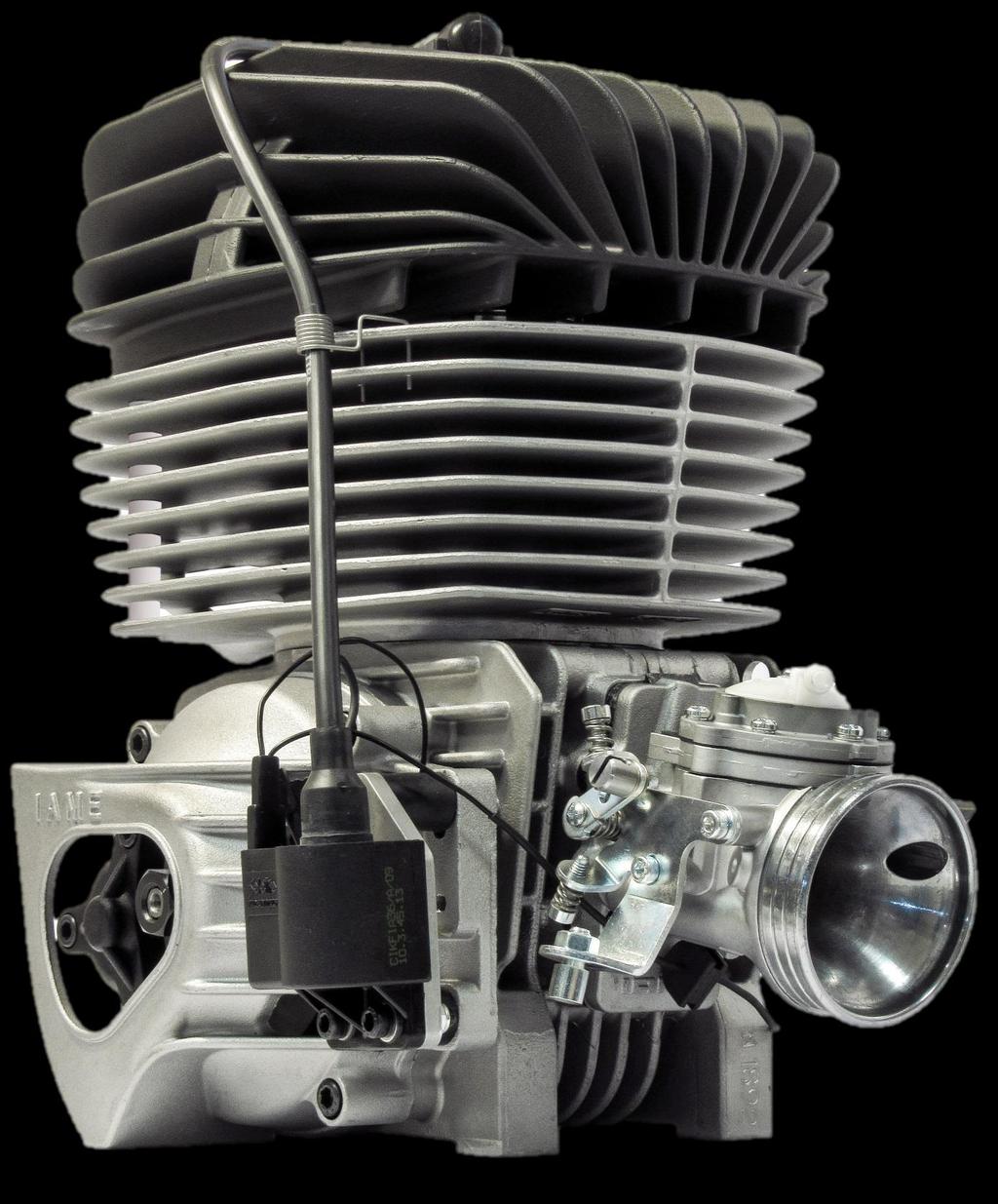
3 GENERAL DESCRIPTION OF ENGINE This engine of the "TaG" series (Touch and Go) has been expressly designed and developed to power karts for hobby racing on closed tracks, destined for this specific purpose. When designing this new line of engines, the technical solutions already adopted for the high performance engines were applied, in order to guarantee the highest reliability of components, when the operating limits are respected. The motor is a single cylinder using the two stroke principle. The cylinder and the crankcase are in aluminium alloy. The pressed in liner is made of centrifugated cast iron, fully machined to guarantee the best possible stability and sliding homogeneity. The head is separated from the cylinder and secured by studs. The crankshaft is built and supported by ball-bearings. The crankshaft is of steel alloy, hardened and tempered, as is the connecting rod which runs on roller bearings. The ignition includes a 2 pole stator/rotor, an H.T. coil, a starter relay and complete wiring harness. The spark is generated also without a battery: therefore, in case of emergency, the engine can be started with an external starter unit. The engine has an integrated electric starter. By pushing the start button, the starter activates a Bendix type gear that engages the starter ring assembled on the clutch. The engine is provided with a dry centrifugal clutch with low maintenance and with interchangeable sprocket. The carburettor is a diaphragm type (series Tillotson HW), it includes an integrated fuel pump and filter, and it is able to operate in any position. The battery (12V - 9Ah) is a sealed, no maintenance battery and is supplied together with a support box, which can be easily adapted to all existing chassis. The exhaust system, included in the engine package, is already tuned and optimized to ensure the best possible performance. 1
4 ENGINE FEATURES OPERATIONAL LIMITS Engine features: Cycle: Original cubic capacity: Original bore: Max. theoretical bore: Stroke: Lubrification : Induction: Carburettor: Cooling: Ignition: Electric Starter: Clutch: OTTO / 2 stroke 100 cm³ mm mm mm max Mixture 5% Reed Valve in crankcase Diaphragm type, Tillotson HW-33A - Ø24mm Free Air Analogical / 2 poles, slotted with internal rotor 12V/0.30 kw Automatic, dry centrifugal ATTENTION: Never exceed the above limits, no obligation of IAME S.p.A. exists in case the above limits are exceeded. Operational RPM limits (the motor not included RPM Limiter): Max.RPM / 1 : RPM CONTENT OF PACKAGING EXHAUST GRUOP Quantity Exhaust muffler spring 2 Exhaust manifold (no restricted / restricted Ø19mm) 1 Exhaust muffler 1 INDUCTION GROUP Tillotson Carburettor HW-33A (Venturi Ø24mm) 1 Inlet Silencer 1 Inlet Silencer Rubber Manifold 1 Inlet Silencer Support + Clamps 1 Carburettor throttle lever cable 1 Inlet manifold carburettor pipe 1 ELECTRICAL GROUP Battery 12V 9 Ah 1 Wiring Harness (with push buttons) 1 Push Buttons Support Bracket 1 Battery Support 1 Battery fix straps 1 Battery Fixing Clamps 2 H.T. Coil 1 Fixing Clamps 8 Sparkplug NGK BR 10 EG 1 Sparkplug Cap 1 MISCELLANEUOS Clutch Cover + Accessories 1 Dual-Lock fixing tape 1 2


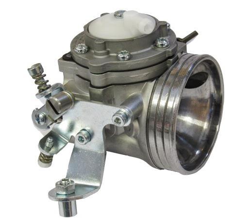
5 ACCESSORIES EXHAUST GROUP BATTERY SUPPORT KIT CLUTCH COVER + H.T. COIL PUSH BUTTONS BRACKET COPERCHIO FRIZIONE WIRING HARNESS TILLOTSON CARBURETTOR INLET SILENCER + FILTER SPARKPLUG KIT 3
 The number normally includes 1 letter, followed by 2 digits numbers, AU and 2 other digits numbers (there can be exceptions in some special cases).")
6 ENGINE IDENTIFICATION NUMBER The engine serial number is marked on the front right part of the clutch side crankcase (see fig.) The number normally includes 1 letter, followed by 2 digits numbers, AU and 2 other digits numbers (there can be exceptions in some special cases). Other numbers stamped on the crankcase or other surfaces of the motor refer to various manufacturing processes and do not identify the motor. NOTE: In case of need for spares and when contacting the IAME Support Centers, please always refer to the Engine Serial Number and to the engine model. 4
7 2- PREPARATION AND INSTALLATION OF THE ENGINE ON THE CHASSIS NOTE: In case the engine is supplied already assembled on the chassis, it is at care of the assembler to follow these instructions. The final customer, in this case, can skip this section and can start reading from section 4. Whenever the engine or a component is disassembled, it is necessary to always follow the under shown instructions for proper reassembly INSTALLATION SKETCH OF THE ENGINE ON THE CHASSIS NOTE: BEFORE INSTALLING THE ENGINE ON THE CHASSIS, CHECK THAT BOTH THE HEAD NUTS AND HEAD COLUMN NUTS ARE PROPERLY TIGHTENED, ACCORDING TO THE TORQUE VALUES IN THE TABLE. 5

 INSERT THE 2 SPRING WASHERS 8mm SUGGESTION: PUT THE ENGINE IN HORIZONTAL POSITION AND PLACE THE SPRING WASHERS IN THEIR SEAT. HELP YOURSELF WITH A SCREWDRIVER.")
8 2.2- EXHAUST MANIFOLD INSTALLATION NOTE: THE ENGINE IS SUPPLIED WITH AN EXHAUST CARD BOARD COVER TO PROTECT THE INTERNAL PARTS. THE EXHAUST GASKET AND STUD BOLTS ARE ALREADY MOUNTED. REMOVE THE NUTS AND THE EXHAUST CARD BOARD COVER. MAKE SURE THAT THE EXHAUST GASKET IS IN SEAT AND INSTALL THE EXHAUST MANIFOLD. Fig.1 (SEE FIG. 1) INSERT THE 2 SPRING WASHERS 8mm SUGGESTION: PUT THE ENGINE IN HORIZONTAL POSITION AND PLACE THE SPRING WASHERS IN THEIR SEAT. HELP YOURSELF WITH A SCREWDRIVER. INSTALL 2 COLOMN NUTS. TIGHTEN TO Nm. 12 POINT ELBOWED WRENCH 13 mm (or 13mm OPEN WRENCH) Fig.2 SUGGESTION: EASIER TIGHTENING (as per Fig. 2) WITH A REDUCED EXTERNAL DIAMETER SOCKET WRENCH OR WITH AN OPEN WRENCH. 6

 Fig.4 POSITION THE SPRING ON THE LEVER. Fig.5 (SEE FIG.")

 CARBURETTOR TIGHTEN THE CARBURETTOR COLUMNS NUT M6 AT")
9 2.3- INSTALLATION CARBURETTOR INSTALL THE GAS CABLE CLAMP ON THE SUPPORT 12 POINT WRENCH 10mm Fig.3 (SEE FIG. 3) TIGHTEN NUT M6 WITH 12 PONT WRENCH 10mm. (SEE FIG. 4) Fig.4 POSITION THE SPRING ON THE LEVER. Fig.5 (SEE FIG. 5) POSITIONING CARBURETTOR: REMOVE THE PLASTIC PROTECTION PLUG LEAVE THE GASKET ON THE ENGINE AND INSTALL IN THIS WAY (SEE FIG.6) CARBURETTOR TIGHTEN THE CARBURETTOR COLUMNS NUT M6 AT 6 8 Nm, WITH A 5mm ALLEN WRENCH T-TYPE. Fig.6 7
 IN THE ENGINE-MOUNT Fig.")
10 FINAL STEP - AFTER THE COMPLETE INSTALLATION OF THE ENGINE ON THE CHASSIS. CONNECT THE FUEL FEED HOSE TO THE INLET FITTING ON THE CARBURETTOR CAP. (SEE FIG. 7) 2.4- PREPARATION AND INSTALLATON OF THE ENGINE-MOUNT NOTE: ALL THE DIMENSIONS IN MILLIMETERS DRILL 4 HOLES (DIAM mm) IN THE ENGINE-MOUNT Fig.7 ENGINE MOUNT HORIZONTAL VIEW 8


 Fig.12 INSTALL THE CHAIN (PITCH: #219). (SEE FIG. 13) Fig.")

11 2.5 INSTALL THE ENGINE ON THE CHASSIS POSITION THE ENGINE ON THE 2 OUTSIDE MAIN RAILS AND FIX THE MOTOR-MOUNT WITH THE TWO CLAMPS. (SEE FIG.11) SUGGESTION: NEVER TORQUE COMPLETELY THE CLAMPS UNTIL THE CHAIN IS INSTALLED AND PROPERLY ALIGNED. Fig.11 CHECK THE ALIGNMENT OF THE ENGINE SPROCKET AND THE AXLE SPROCKET WITH A STRAIGHT EDGE. (SEE FIG. 12) Fig.12 INSTALL THE CHAIN (PITCH: #219). (SEE FIG. 13) Fig.13 MOVE THE ENGINE ON THE RAILS TO ADJUST THE CHAIN TENSION. ATTENTION: THE PLAY OF THE CHAIN MUST BE APPR. 16mm (1/2 3/4 inch) MEASURED IN THE SHOWN POINT. (SEE FIG. 14) 15mm Fig.14 COMPLETELY TIGHTEN THE ENGINE MOUNT SCREWS. 9

 TIGHTEN THE 3 SCREW AT 8 10 Nm ATTENTION: ALWAYS MAKE SURE THAT THE GROUND CABLE")

12 2.6 INSTALL THE CLUTCH COVER WITH H.T. COIL ALLEN WRENCH 5 mm Fig.15 REMOVED THE 3 SCREWS TCEI M6x30 FROM THE CRANKCASE (SEE FIG. 15) AND INSTALL THE CLUTCH COVER WITH THE H.T. COIL. (SEE FIG.16) TIGHTEN THE 3 SCREW AT 8 10 Nm ATTENTION: ALWAYS MAKE SURE THAT THE GROUND CABLE ALWAYS CONNECTS THE COIL WITH THE ENGINE. AN INADEQUATE GROUNDING COULD DAMAGE THE IGNITION BEYOND REPAIR. THE POSITION OF THE H.T. COIL HAS BEEN CHOSEN TO BE AS FAR AS POSSIBLE FROM THE EXHAUST AS THE EXCESSIVE HEAT COULD DAMAGE THE COIL BEYOND REPAIR. Fig.16 10

. JUST TIGHTEN A LITTLE TO KEEP THEM IN PLACE ON THE CHASSIS.")


 THE BOX MUST BE FIXED WITH AT LEAST ONE SCREW FOR EACH CLAMP.")
13 2.7- ELECTRICAL CONNECTIONS (refer to the attached electrical scheme) NOTE: FOR A CORRECT INSTALLATION FOLLOW THE UNDER SHOWN INSTRUCTIONS. INSERT BATTERY FIXING STRIPE IN THE DEDICATED SLOTS. (SEE FIG. 17) PLACE THE BATTERY SUPPORT CLAMPS ON THE CHASSIS TUBE, FIX THEM THROUGH THE SPECIFIC SCREWS ON THE SUPPORT PIPES (SCREW TE M6x25 SEE FIG. 18). JUST TIGHTEN A LITTLE TO KEEP THEM IN PLACE ON THE CHASSIS. Fig.17 (HEXAGONAL MALE KEY 5mm) Fig.18 PLACE THE BATTERY SUPPORT, THE PUSH BUTTONS BRACKET BETWEEN THE CLAMP AND THE BATTERY SUPPORT, (SEE FIG. 19), THEN TIGHTEN THE COMPONENTS WITH A 10mm SOCKET WRENCH. AFTER TIGHTENING THE BATTERY SUPPORT UPPER SCREW, COMPLETELY TIGHTEN ALSO THE CLAMPS SCREWS. (SOCKET WRENCH 10mm) TROQUE THE SCREWS AT 8 10 Nm (ALLEN WRENCH 5mm) TORQUE THE SCREWS AT 8 10 Nm (SEE FIG. 19 and 20) THE BOX MUST BE FIXED WITH AT LEAST ONE SCREW FOR EACH CLAMP. FIX WITH MORE SCREWS DEPENDING ON CHASSIS. Fig.19 NOTE: THE DIFFERENT HOLES ON THE BATTERY SUPPORT AND ON THE BRACKET, ALLOW TO ADAPT THE SYSTEM TO EVERY CHASSIS. Fig.20 11


. Fig.")


14 PLACE THE STARTER BUTTON IN THE PROPER HOUSING AND FIX IT THROUGH THE PROVIDED NUT. (SEE FIG.21) FIX AND PLACE THE BUTTON WITH THE FASTON ORIENTED AS IN THE FIGURE: Fig.21 PASS THE CABLE WITH THE BUTTONS TERMINALS IN THE BRACKET, CONNECT THE 2 FASTONS TO THE STARTER BUTTON AND TIGHTEN THE STOP RED BUTTON WITH THE PROVIDED NUT (SEE FIG. 22). Fig.22 NOTE: THE 2 START BUTTON FASTONS CAN BE INVERTED, THIS DOES NOT CAUSE WORKING PROBLEMS. CONNECT THE BATTERY CABLES TO THE FASTONS AND TIGHTEN THE STRAP ON THE CABLES. Fig.23 (SEE FIG. 23) CONNECT THE STARTER MOTOR CABLE TO THE CONNECTOR OF THE CABLES ADAPTER. Fig.24 (SEE FIG.24) ATTENTION: MAKE SURE THAT THE LOCKING OF THE TWO CONNECTORS IS MADE PROPERLY TO ENSURE THE GOOD CONTACT OF THE TERMINALS. CONNECT THE ADAPTER TO THE CABLES CONNECTOR. (SEE FIG.25) THE 2ND ADAPTER TERMINAL MUST BE CONNECTED TO THE GROUND. Fig.25 12


 CONNECT THE MALE FASTON OF THE STOP CABLE TO")


15 FIX THE KIT CABLES THROUGH A STRAP ACCORDING TO THE CHASSIS AND THE NEED. Fig.26 (SEE FIG.26) CONNECT THE SUPERSEAL 4 WAYS MALE FASTON CONNECTOR TO THE FEMALE CONNECTOR OF THE STOP CABLE. Fig.27 (SEE FIG.27) CONNECT THE MALE FASTON OF THE STOP CABLE TO THE FEMALE FASTON CONNECTOR OF THE INGNITION. Fig.28 (SEE FIG. 28) CONNECT THE FEMALE FASTON OF THE INGNITION CABLE ON THE H.T. MALE FASTON. Fig.29 (SEE FIG.29) SCREW THE SPARK PLUG CAP ON THE COIL HIGH VOLTAGE CABLE. Fig.30 (SEE FIG. 30) Fig.37 13


 Fig.33 2.9 ASSEMBLY OF THE EXHAUST SYSTEM NOTE: SEE SECTION 3.8 FOR THE WARNINGS ON EXHAUST SYSTEM.")
16 FIX THE CUP ON THE A.T. CABLE THROUGH A PLASTIC STRAP (SEE FIG. 31). Fig.31 MOUNT THE SPARK PLUG PROVIDED WITH THE ENGINE TORQUE AT Nm ASSEMBLY THE CUP ON THE SPARK PLUG. Caution should be taken when installing the spark plug. Always clean and inspect the spark plug threads before installation. Always apply anti seize compound, grease or oil. - NEVER INSTALL THE SPARK PLUG WITHOUT SOME LUBRICATION - You should be able to freely turn the plug into the head using only your fingers to turn the plug. Do not force the plug with a tool or damage will occur. After rotating the plug into the head by hand only. Torque to lbs-in (20 26 Nm). 2.8 ASSEMBLY OF THE INLET SILENCER Fig.32 MAKE SURE THAT THE INLET SILENCER IS POSITIONED WITH THE HOLES UPSIDE AND THAT THEY ARE NOT OBSTRUCTED. TIGHTEN THE CLAMP ON THE INLET SILENCER SUPPORT ON THE CARBURETTOR AND FIX THE INLET SILENCER WITH THE DEDICATED CLAMP ON THE CHASSIS TUBE. (SEE FIG ) Fig ASSEMBLY OF THE EXHAUST SYSTEM NOTE: SEE SECTION 3.8 FOR THE WARNINGS ON EXHAUST SYSTEM. ASSEMBLY THE EXHAUST SILENCER ON THE EXHAUST MANIFOLD PREVIOUSLY MOUNTED ON THE CYLINDER AND FIX IT WITH THE PROVIDED SPECIFIC SPRINGS. (SEE FIG.34). FIX THE SILENCER ON THE CRADLE SUPPORT OF THE CHASSIS. THE ENGINE IS NOW READY TO START Fig.34 14
17 3.1- MIXTURE OIL AND FUEL Use unleaded Premium gasoline 98 RON (minimum), mixed with oil at 5% (20:1). Please note that castor oils create gummy residues that give origin to carbon deposits causing incrustations, it is necessary to check and clean the piston and the head at least every 5 hours. Recommended oils : WLADOIL RACING K2T ELF HTX 976 Once the tank has been filled, make sure that the fuel flows to the carburettor before starting the engine. Avoid pump fuel to the carburettor by operating the electric starter, as it causes a useless battery discharge. SUGGESTION: Remove the fuel tube on the carburettor and the breather pipe of the recovery tank breather and blow into the breather pipe till the fuel comes out from the tube on the carburettor. Make sure that there are no air bubbles into the tube. Connect the tube on the carburetor and on the breather. 15
: 1 T.O. According to various factors as altitude and environmental temperature, it might be necessary to adjust the carburettor settings to optimize the engine performance.")
18 3.2- CARBURETTOR SETTING SCREW ( I ) IDLE SCREW SCREW ( L ) LOW SPEED MIXTURE SCREW ( H ) HIGH SPEED MIXTURE MMMIXTURESCREW 1 T.O. * RICH LEAN 1 ¼ T.O. ¾ T.O. 1 ½ T.O. * T.O. = TURNS OPEN Generally the correct setting of the carburettor screws is the following: L (close the screw completely and then open): 1 T.O. H (close the screw completely and then open): 1 T.O. According to various factors as altitude and environmental temperature, it might be necessary to adjust the carburettor settings to optimize the engine performance. ATTENTION : - Never lean excessively the mixture, the engine may overheat and seize up - Never force the screws H and L completely. This may damage the screws housing and make the carburetor unusable. - The carburettor setting must be made on warm engine. (H) Torque the screw completely and open at: 1 T.O. (L) Torque the screw completely and open approx. at 1 T.O. (I) Turn the screw till to the contact with throttle lever and screw futher of 1 ½ T.O. Start the engine and warm it. If the if RPM is too high, set the screw l counterclockwise, untill the clutch is disengaged. Unscrew counterclockwise untill max RPM is reached. Unscrew just enough wich allows to reach the idle. If RPM decreases (L) Counterclockwise setting If RPM increases Continue to screw in a clockwise direction until the maximum RPM possible is reached. Unscrew just enough to allow a minimum, tending to rich. Engine is now idling, turns at max gettable RPM and will be tending on rich. Adjust counterclockwise L screw until to rpm is reached. Check again L screw for an optimal setting The H screw setting can be only in working. Set H screw to achieve the best possible RPM on straight. Set clockwise to increase RPM and counterclockwise to reduce RPM. Set L screw on rich of 1/8 ¼ T.O. Bad acceleration Go back to the idle and check acceleration for a quick response and smooth pick-up. Good acceleration The engine is ready 16
19 3.3- STARTING AND STOPPING THE ENGINE The engine start is achieved by pushing the black rubber button on the bracket. If the engine does not start, stop and try again. If the engine does not start within 5 seconds (check that gasoline flows to the carburettor), stop the procedure and try after about 15 seconds. Short and frequent tries are better than long ones. In case the engine can't be started, refer to the Sec "Troubleshooting. Stop the engine by pressing the red button on the bracket. Keep the stop button pressed until the engine is completely stopped ENGINE RUNNING-IN The running-in must be made following a few basic rules: 1. Carburation setting. Start with basic setting on the rich side. 2. Warm the engine gradually for 5 minutes, driving some laps at low speed, smoothly closing and opening the accelerator (if a tachometer is installed, never exceed RPM). Never keep the same RPM for a long time but alternate the speed. 3. Gradually increase the vehicle speed for about 5 minutes (with ¾ throttle opening). Never keep the same RPM for a long time but to alternate it. 4. Increase the speed driving some laps, for about 5 minutes (with acceleretor fully opened on circuit twisty parts and enrich the carburation at half straight (cover with the hand the inlet hole on the inlet silencer for an istant, keeping the throttle open). WARNING: Very important, when the engine is cold, check the tightening of the cylinder head nuts after the first hour of use, according to the torque table to the of this manual. Once the running-in is over, with cold engine, check the tightening of the exhaust pipe nuts as during the 1st running-in, the nuts can get loose (refer to the attached table) INLET SILENCER Make sure that the inlet holes of the inlet silencer are towards the upper side and they are not covered. Make sure that the fixing strapis not loosen and that the inlet silencer is well fastened to the chassis through the specific strap. Occasionally, check the presence of oil deposits in the inlet silencer. If necessary, remove the manifold with filter and clean the inside with gasoline or a diluent EXHAUST SYSTEM WARNINGS Make sure that the silencer fixing springs are well hooked. In case of damage replace the broken springs. Never race the kart without the two spring well hooked, as the silencer become dislodged. It is recommended to open the exhaust pipe end every hours and make sure that the holes on the counter cone are not obstructed by incrustation. 17
20 3.7- EXHAUST GAS TEMPERATURE PROBE The exhaust muffler is not provided with a temperature probe lodgment. If necessary, it is possible to install the probe support and as indicated in the figure. Whenever you wish to employ the probe, please proceed as shown in the figure below. drill exhaust Ø4.2 for cylindrical probe drill exhaust Ø4.2 and thread M5 for threaded probe 3.8- CENTRIFUGAL CLUTCH The engine has a low maintenance dry centrifugal clutch. The following prescriptions, if carefully followed, will allow a clutch longlife. When starting the engine, make sure that the brake pedal is fully pressed to avoid any sudden accelerations. WARNING: Once the engine is started, absolutely avoid useless accelerations (glazed of the friction and/or skids) which can overheat and deteriorate the clutch group before time. Grease the chain before each session. Check the engine sprocket, after each test or race and replace it, if necessary. A bad alignment of the engine sprocket with the axle sprocket or chain grease lack can irreparably damage the sprocket. When it is necessary to check the clutch?: Every 5 hours of standard use. When metallic noises from the clutch are heard. If the kart dragging speed exceeds RPM. When the clutch has overheated (presence of smoke or smell of burning). Remove the clutch cover and the clutch drum to check the clutch. When it is necessary to replace the clutch?: whenever the thickness of the friction material is lower than 1.5mm on point A of the picture, if the body diameter is lower than 83mm, or when is very rough (wear and deterioration of the friction material due to overheating). WARNING: In case the friction material is fully worn out and there has been a prolonged contact between the clucth body and clutch drum, it also necessary to replace the clutch drum. A A A 18
21 3.9- INSTRUCTIONS FOR THE DISASSEMBLY / ASSEMBLY OF THE CLUTCH GROUP WARNING : The following operations can be made by a skilled mechanic, with the proper tools shown in the text ; otherwise, it is necessaty to apply to an Authorized Service Center. Refer to the following drawing during the different operations Drum retaining nut 6 Sprocket 11 Clutch body 2 External washer 7 Clutch drum 12 Starter wheel 3 Roller cage 8 Internal washer 4 O Ring 9 Loocking nut 5 Screw 10 Screw OPERATIONS TOOLS Clutch disassembly 1. Remove the clutch cover (3 screws TCEI M6). Allen wrench 5mm male T type 2. Remove the bendix cover and place the starter wheel locking tool. Starter wheel locking tool : ATT Remove the retainer nut. (N 1 - M10 nut) Ring wrench 17 mm 5 4. Remove the external washer, the complete drum with roller cage, the internal washer. 5. With the starter wheel locking tool in place, remove the M20x1 clutch hub nut. Starter wheel locking tool: ATT.037 Allen wrench 27 mm WARNING: Unscrew clockwise as the nut has left-hand thread 6. Remove the clutch hub and the starter wheel from the crankshaft through clutch puller. Clutch puller : ATT.026 Allen wrench 12mm male 7. Remove the starter wheel (3 screws M6 TCEI) Allen wrench 5mm male T type 19
22 Before assembling the clutch, wash with the diluent : the shaft cone, the starter wheel and the clutch drum. Clutch assembly 1. Asseble the starter wheel on the clutch hub by matching the 3 holes and the dragging pin (3 screws TCEI M6) WARNING: it is necessary to always install the Ø7mm pin, as eventual kicks could shear the screws. 2. Place the clutch hub and the starter wheel on the shaft. Allen wrench 5mm male T type (torque at Nm) Apply Loctite threadlocker Apply Loctite 641 for coaxial locking. 3. Assemble the fixing nut, clutch hub and starter wheel, Starter wheel locking tool : ATT.037 through the starter wheel locking tool and the allen Allen wrench 27 mm. wrench 27mm. (torque at Nm) WARNING: Screw counter-clockwise as the nut has left-hand thread. 4. Assemble the internal washer. WARNING: the bevel of the washer hole must be towards the shaft. Clean the roller cage and grease it before assembling it on the shaft. 5. Mount the clutch drum and the external washer. WARNING: the bevel of the washer hole must be towards the shaft. 6. With the starter wheel locking tool in place, tighten the drum retainer nut (nut M10). 7. Reassemble the clutch cover (3 screws TCEI M6) Starter wheel locking tool: ATT.037 Ring wrench 17 mm (torque at Nm) Allen wrench 5mm male T type (torque at 8 10 Nm) 3.10 BATTERY The battery (12V 9Ah) is selaed and without maintenance. In order to prolong the battery life, it is recommended to follow these few prescriptions: When the tension drops below 12.6V, it is necessary to recharge the battery. The max allowed recharging current is 1.8A. The ideal recharge is achieved with an average current of 0.8 1A. (recharging time of approx 10 h.) at an environmental temperature between 0 e 40 C. WARNING: An ovecharge or an extremely quick charge with excessive current can damage the battery components (battery swelling). Choose a battery charger with the following characteristics : Feeding tension : 90/250 Vac 50/60 Hz Outlet tension : 15 V full charge 13.8 stand-by Max outlet current : 2A full charge During the transport and/or the storage, the battery could loose part of its charge due to the self-discharge (0.1% max. per day). Fully charge the battery before use. WARNING: Always connect the + (positive) pole before the - (negative) pole. Always disconnect the battery in opposite order. Recharge the battery at least once every 6 months 20
23 Never let the battery tension drop under 8V as under this limit the battery can not be used and it will have to be replaced. Never put the battery in contact with solvents, oils, plastifiers or rags containing such elements as the battery external case could be damaged. Never press and/or bend or overheat the battery terminals (for ex. by welding). Other recommendations Avoid the generation of sparks or flames upun or around the battery. Never short-circuit the terminals. Never open the battery or throw in the fire In case the electrolyte (diluted Sulfuric Acid) gets in contact with skin or clothes, wash immediately with water. In case it gets in touch with eyes, wash and apply for medical assistance. Carefully check the external battery case and replace it in case of damages, swellings of the case or the battery cover. Before use, clean the battery from dust or other dirt and check that the poles are not oxydized or damaged. At the end of the battery life, never throw it in the garbage but deliver it to an authorized waste disposer SPARK PLUG AND THERMAL DEGREE The engine is supplied with a standard NGK BR10EG spark plug. It represents a good compromise between the need of a good running-in and the racing needs in standard conditions. The use of different spark plugs is possible and, as a general information, we are attaching a correspondence list among several brands, according to the thermal degree which represents the capacity of the spark plug to dissipate the inside heat. The colour of the various parts of the spark plug more exposed to the combustion flames gives a good indication of the suitability of the thermal degree and on the carburetion. It is necessary though to understand which of the two parameters has to be modified and only tells how to identify the spark plug with a most suitable thermal degree, as lean or rich mixtures can generate the same final look which can also be achived with spark plugs respectively too hot or too cold. See the table for information purposes : A spark plug too hot shows the symptoms aside listed. WARNING: employ a spark plug too hot than a standard one, with cold or rainy weather. A spark plug with suitable thermal degree shows: A spark plug too cold shows the symptoms aside listed. WARNING: employ a spark plug too cold than a standard one, with very hot weather Extremely clear colour, porous and calcified look of the electrodes and of the internal insulation. Ignition irregularity, preignition and detonation with tendency to perforate the top of the piston. Note: some of these symptoms can be achieved with lean mixtures. Shade colour, from the insulator end and of the electrode, from yellow grey till to dark brown for mixture respectively lean or rich. Insulator end and elctrodes covered byblack matt soot Ignition difficulties. Note: a wet or oily electrode could also mean a too rich misture. 21
24 INDICATIVE SPARK PLUG COMPARISON TABLE BASED ON THERMAL DEGREE HOT BOSCH NGK CHAMPION WO8CS BR9EG N54R WO7CS BR10EG N52R WO6CS BR11EG CHOICE OF THE SPROCKETS RATIO COLD The life of an engine depends upon many factors but most of all upon the speed at which the engine is operated. If an engine is normally operated at speeds higher than what recommended by the manufacturer, the wear and stress of the different components (conrods, roller cages, bearings etc.) will be such as to drastically reduce the life of the engine itself. It is therefore extremely important that the user respects the operating limits imposed by the manufacturer. The operating limit for the Reedjet 100cc engine is RPM. ATTENTION: Never exceed the above limit. No obligation of IAME exists in case the above limit is exceed. In case the user wishes to optimize the sprocket ratio on the track, in order to achieve the best possible performance and without overloading the engine, follow the under shown recommendations. The engines are supplied with a 10,11,12 or 13 teeth sprocket (pitch: #219). Table 1 shows the various ratios between the sprocket on the axle and the engine sprocket given the different axle sprockets. Tab.1 Sprocket Ratio Teeth n - Engine sprocket Sprocket Ratio Teeth n - Engine sprocket Starting Gear Teeth n Axle Gear ,2 6,55 6,00 5, ,3 7,55 6,92 6, ,3 6,64 6,08 5, ,4 7,64 7,00 6, ,4 6,73 6,17 5, ,5 7,73 7,08 6, ,5 6,82 6,25 5, ,6 7,82 7,17 6, ,6 6,91 6,33 5, ,7 7,91 7,25 6, ,7 7,00 6,42 5, ,8 8,00 7,33 6, ,8 7,09 6,50 6, ,9 8,09 7,42 6, ,9 7,18 6,58 6, ,18 7,50 6, ,27 6,67 6, ,1 8,27 7,58 7, ,1 7,36 6,75 6, ,2 8,36 7,67 7, ,2 7,45 6,83 6,31 22
25 For the operation limit of RPM the following table (Tab.2) has been prepared During the track tests the use of a tachometer recording the max obtained engine RPM is recommended. Use spark plug caps with a resistance of 5KΩ to avoid eventual interferences between the ignition and the tachometer and/or telemetry. The following example should clarify the procedure for the optimization of the sprocket. Assume to use the engine with Z=10 teeth engine sprocket and that during the preliminary track tests a Z=72 teeth axle sprocket has been used. From table 1 with Z=10 as engine sprocket and Z=72 on the axle sprocket, a ratio of 7.20 is found. Make a few laps on the track and let s assume you read max engine RPM. From the table 2 to achieve a max RPM of RPM (operating limit for the KA100 engine) a sprocket ratio from 7.61 and 7.82 should be used (having used, during the tests, a sprocket ratio of 7.2 and having achieved RPM max.). From table.1, with these values, a sprocket ratio of 10:76 / 10:78 should be used or, having a Z=11 on the engine sprocket, a ratio 11:85 should be used. Engine max RPM during tests Sprocket ratio to achieve max RPM Tab. 2 Sprocket ratio 6,5 6,7 6,9 7,1 7,3 7,5 7,7 7,9 8,1 8,3 8,5 8,7 8,9 9,1 9, ,50 7,73 7,96 8,19 8,42 8,65 8,88 9,12 9,35 9,58 9,81 10,04 10,27 10,50 10, ,39 7,61 7,84 8,07 8,30 8,52 8,75 8,98 9,20 9,43 9,66 9,89 10,11 10,34 10, ,28 7,50 7,72 7,95 8,17 8,40 8,62 8,84 9,07 9,29 9,51 9,74 9,96 10,19 10, ,17 7,39 7,61 7,83 8,05 8,27 8,49 8,71 8,93 9,15 9,38 9,60 9,82 10,04 10, ,07 7,28 7,50 7,72 7,93 8,15 8,37 8,59 8,80 9,02 9,24 9,46 9,67 9,89 10, ,96 7,18 7,39 7,61 7,82 8,04 8,25 8,46 8,68 8,89 9,11 9,32 9,54 9,75 9, ,87 7,08 7,29 7,50 7,71 7,92 8,13 8,35 8,56 8,77 8,98 9,19 9,40 9,61 9, ,77 6,98 7,19 7,40 7,60 7,81 8,02 8,23 8,44 8,65 8,85 9,06 9,27 9,48 9, ,68 6,88 7,09 7,29 7,50 7,71 7,91 8,12 8,32 8,53 8,73 8,94 9,14 9,35 9, ,59 6,79 6,99 7,20 7,40 7,60 7,80 8,01 8,21 8,41 8,61 8,82 9,02 9,22 9, ,50 6,70 6,90 7,10 7,30 7,50 7,70 7,90 8,10 8,30 8,50 8,70 8,90 9,10 9, ,41 6,61 6,81 7,01 7,20 7,40 7,60 7,80 7,99 8,19 8,39 8,59 8,78 8,98 9, ,33 6,53 6,72 6,92 7,11 7,31 7,50 7,69 7,89 8,08 8,28 8,47 8,67 8,86 9, ,25 6,44 6,63 6,83 7,02 7,21 7,40 7,60 7,79 7,98 8,17 8,37 8,56 8,75 8, ,17 6,36 6,55 6,74 6,93 7,12 7,31 7,50 7,69 7,88 8,07 8,26 8,45 8,64 8, ,09 6,28 6,47 6,66 6,84 7,03 7,22 7,41 7,59 7,78 7,97 8,16 8,34 8,53 8, ,02 6,20 6,39 6,57 6,76 6,94 7,13 7,31 7,50 7,69 7,87 8,06 8,24 8,43 8, ,95 6,13 6,31 6,49 6,68 6,86 7,04 7,23 7,41 7,59 7,77 7,96 8,14 8,32 8, ,87 6,05 6,23 6,42 6,60 6,78 6,96 7,14 7,32 7,50 7,68 7,86 8,04 8,22 8, ,80 5,98 6,16 6,34 6,52 6,70 6,88 7,05 7,23 7,41 7,59 7,77 7,95 8,13 8, ,74 5,91 6,09 6,26 6,44 6,62 6,79 6,97 7,15 7,32 7,50 7,68 7,85 8,03 8,21 23

.")

 - REMOVE THE STARTER")
. Fig.")
26 3.13- REPLACEMENT OF THE STARTER BRUSHES OPERATIONS PICTURES DISASSEMBLE THE STARTER MOTOR Fig.1 - LOOSE THE SCREW M6x30 ON THE ADDITIONAL STARTER SUPPORT (See Fig.1). (5mm ALLEN WRENCH T TYPE) - REMOVE THE ADDITIONAL STARTER SUPPORT 3 SCREWS M6x25 (See Fig.2). Fig.2 (5mm ALLEN WRENCH T TYPE) - REMOVE THE STARTER SUPPORT 4 SCREWS M6x35 (See Fig.3). Fig.3 (5mm ALLEN WRENCH T TYPE) - LOOSE THE 3 SCREWS M6x35 TO REMOVE THE STARTER (See Fig.4). (5mm ALLEN T TYPE) Fig.4 - EXTRACT THE STARTER MOTOR (See Fig.5). Fig.5 24
27 OPENING THE STARTER MOTOR - UNSCREW THE M4 SCREW FIXING THE INPUT CABLE Fig.6 Fig.1 (See Fig.6) (SCREWDRIVER) - UNSCREW THE 3 M5 C SCREWS (See Fig.7) Fig.7 (SCREWDRIVER) 25
 Fig.4 Fig.8 - EXTRACT THE ROTOR FROM THE STARTER MOTOR HEAD (see Fig. 9) Fig.")

28 - REMOVE THE DRUM FROM THE STARTER MOTOR KEEPING THE ROTOR IN ITS SEAT (BE SURE TO HOLD THE ROTOR ON ITS TOOTHED SIDE TO PREVENT THE BRUSHES FROM FALLING OUT FROM THEIR SEAT (see Fig. 8) Fig.4 Fig.8 - EXTRACT THE ROTOR FROM THE STARTER MOTOR HEAD (see Fig. 9) Fig.9 ATTENTION: WHEN EXTRACTING THE ROTOR, THE BRUSHES MAY SPRING OUT FROM THEIR SEATS. REPLACING THE BRUSH A Fig.10 - UNSCREW THE 2 SCREWS M4 "D" RETAINING THE PLATE E (see Fig.10). (SCREWDRIVER) - REMOVE THE LITTLE RUBBER CAP F (see Fig.11). Fig.11 (PLIERS) SUGGESTION: SLIGHTLY OIL THE TIN PLATE TERMINAL END, TO MAKE THE EXTRACTION OF THE LITTLE RUBBER CAP EASIER. 26
 - REMOVE SPRINGS Fig.")
 Fig.9 Fig.")

29 - REMOVE THE SILICON FROM BRUSHES WITH A SCREWDRIVER (see Fig. 11) - REMOVE SPRINGS Fig.12 - REMOVE THE BRUSH MAKING PRESSURE ON THE TIN PLATE TERMINAL EXTERNALLY (see Fig. 13) Fig.9 Fig.13 - INSTALL NEW BRUSH TERMINAL (See Fig.14). - PLACE THE LITTLE RUBBER CAP ON THE TERMINAL. Fig.14 - REINSTALL THE PLATE AND FIX IT WITH THE 2 SCREWS M4 (See Fig.15). (SCREWDRIVER) Fig.15 27
 - EXTRACT THE BRUSH - FIX THE NEW BRUSH WITH SCREW M6 (SCREWDRIVER) CLOSING THE")


30 REPLACEMENT OF THE BRUSH B Fig.16 - LOOSE THE SCREW M3 G (See Fig.16) - EXTRACT THE BRUSH - FIX THE NEW BRUSH WITH SCREW M6 (SCREWDRIVER) CLOSING THE STARTER - INSERT THE NEW BRUSH SPRING "A" INTO ITS SEAT. - INSTALL THE BRUSH. - KEEP THE BRUSH IN PLACE BY PRESSING TOWARDS THE OUTER AND CLAMP IT WITH AN IRON WIRE BENT AS A HOOK. REPEAT THE SAME PROCEDURE TO INSTALL THE BRUSH "B" (See Fig.17). Fig.17 - INSTALL THE ROTOR BETWEEN THE BRUSHES AND CHECK THAT THEY ARE ALWAYS IN CONTACT WITH THE CYLINDRIC COPPER PART OF THE ROTOR, EVEN WHEN THEY ARE RELEASED. (See Fig.18). Fig.18 SUGGESTION: TO IMPROVE THE BRUSHES LIFE, SECURE THE LITTLE WIRES WITH SILICONE (See Fig.19). Fig.19 28
. Fig.20 - TORQUE THE 3 SCREWS M5 (see Fig.")
31 - CHECK THAT THE O-RING "H" IS INSTALLED ON THE STARTER HEAD. - INSERT THE STARTER DRUM ON THE HEAD BEING CAREFUL TO PREVENT THE ROTOR FROM ROTATING AND TO PREVENT THE BRUSHES FROM FALLING OUT OF THEIR SEAT (see Fig. 20). Fig.20 - TORQUE THE 3 SCREWS M5 (see Fig.21). (SCREWDRIVER) - CHECK THAT THE STARTER ROTOR ROTATES FREELY. Fig.21 - CONNECT THE INPUT WIRING TO THE STARTER WITH THE SCREW M4 (see Fig.22). Fig.22 (SCREWDRIVER) 5 ASSEMBLING THE STARTER - PLACE THE STARTER IN SEAT (see Fig.23). PUT SOME OIL ON THE O-RING TO EASE INSTALLATION N 3 SCREWS TCH M6x35 TORQUE AT 8 10 Nm ( in-lb ) - INSTALL THE STARTER ON THE CRANKCASE (N 4 SCREWS M6x35). - INSTALL THE ADDITIONAL SUPPORT (N 3 SCREWS M6x25) AND TORQUE THE SCREW M6x30 ON THE SUPPORT (see Fig.23). (5mm ALLEN WRENCH T- TYPE) TORQUE ALL THE SCREWS AT A 8 10 Nm (70 90 in-lb) Fig.23 29
 Engine sprocket Check wear Check alignment with axle sprocket Engine")
32 3.14- SCHEDULE MAINTENANCE Following some simple maintenance standards will allow the engine to perform more reliably and have a longer life. SCHEDULE COMPONENTS ACTIONS AND COMMENTS Before each use Flexible spring Check status Muffler Check status and fixing (springs) Engine sprocket Check wear Check alignment with axle sprocket Engine chain Check wear, tensioning and chain lubrication Battery Check status and charge Cables and connectors Check status and restore the connections Grounding engine Check status and restore the connections Battery support, bracket and Check torques clamps After each use Battery Disconnect Chain Lubrification Engine External cleaning Every 5 10 hours Bendix starter Remove cover (see fig.) and clean internally. Exhaust muffler Inlet silencer Engine head Clutch Remove muffler end, clean Open, clean Open, clean Open, check status of parts and if necessary replace part. Every 7 hours Piston and con-rod assembly Check and replace worn parts Every 60 hours Crankshaft Replace worn parts Every 30 to 60 hours Main bearings Replace worn parts 30
33 3.15- TROUBLESHOOTING Here below there are some of the most common problems, the possible causes and the recommended solutions to solve them. PROBLEMS PROBABLE CAUSES SOLUTIONS Starter will not crank when pushing Bad connections on starter cables Check connections and tighten the start button Bad grounding Check connections and tighten Damaged cables Replace them Battery connection loose Check and tighten connections Battery discharged Recharge or replace battery Damaged starter Check Starter cranks but engine won't start Bad cable connections Check that connectors are properly connected. Bad H.T. Coil connections or coil Check/replace failure Bad H.T. coil grounding Check grounding Wet spark plug Replace Malfunction on induction system Check status and connection on fuel pipe Replace mambranes and gaskets on carburettor Pushing the start button, the engine Bad harness connections Check connectors starts but turns off after a short time. Bad carburettor setting (screw I) Check carburettor setting (see sect. 3.2) The starter turns also after Battery not sufficiently charged Remove the positive pole of the releasing the start button. (sticking of the starter relay) battery to stop the engine and recharge the battery. The engine stops at minimum Bad setting of idle screw on Check carburettor setting carburettor ( screw L) (see sect. 3.2) The engine shows a performance Bad compression Check piston status drop Bad carburettor setting Check carburettor setting (see sect. 3.2) Insufficient power system Check fuel flow and inlet filter. Blocked inlet silencer Check and clean Burning smell, presence of smoke Clutch overheating Check the clutch status (see sect. 3.8) Clutch engages at too high RPM Excessive wear of the friction Check the clutch status material (see sect. 3.8) Too much noise coming from the Damaged flexible Check and replace if necessary exhaust system Damaged or lost springs Damaged or lost insulating tape Damaged exhaust pipe 31


34 3.16- MAIN PRESCRIPTIONS ENGINE CRANKSHAFT MATCHING THE PISTON Bearing seat diameter on new engine Refer to the attached table to define the state of wear of the drive shafts. Replace when size is lower than 0.03mm vs. original. The replacement operation must be carried out after about a use of 60 hours. MAX ALLOWED OVALIZATION ON CONROD ATTENTION: Clearance between piston and liner must be: / 0.095mm. If clearance is higher than 0.14mm, must be replaced the piston. An inspection must be carried out after about a use of 45 liters or 5 hours of use, and the pistons are measured at 17.5mm from bottom. The replacement operation must be carried out about a use of 10 hours or 80 litres. Size of the liner to be matched with piston is marked on top of piston. Allowed ring gap mm. Max. allowed ovalization between A and B on new conrod: 0.002mm Max. allowed ovalization between A and B on used conrod: 0.01mm An inspection must be carried out after about 30 hours use. When ovalization reaches 0,01mm (the difference between the measured diameter in the positions shown below A and B ) the conrod must be replaced. The replacement operation must be carried out after about a use of 60 hours. ESTIMATED AVERAGE LIFE OTHER COMPONENTS Big End Conrod Roller +Bearing +Crankpin +Silver washer Little End Conrod +Roller Bearing +Piston Pin = 30 hours = 10 to 20 hours 32
35 3.17- WEAR STATUS EVALUATION CHART - BEARINGS AND HALF CRANKSHAFT NOTE: ALWAYS CHECK DIMENSIONS IN DIFFERENT POINTS ON THE CIRCUMFERENCE, LOOKING FOR EVENTUAL OVALIZATIONS. The following chart shows the ovalization limits over which replacement is required MEASURED PART (MEASURING INSTRUMENT) LIMITS Replace after Hours for Using CRANKSHAFT BEARING SEAT (MICROMETER /100) MIN. Ø h CRANKSHAFT BEARINGS (1/100 BORE GAUGE WITH CHECK RING Ø25) *MAX. Ø h * ATTENTION: THE MEASURED VALUE ON THE BEARING MUST ALWAYS BE COMPARED WITH THE SEAT VALUE (ON SHAFT AND/OR BALANCE SHAFT), TO CHECK THAT PLAY BETWEEN SHAFT AND BEARING DOES NOT EXCEEDTHE LIMIT VALUE OF 0.05mm. 33
36 3.18- LITTLE / BIG END CONROD BEARINGS CLEARANCE 34
37 3.19- ENGINE AND ACCESSORIES PRESERVATION When the engine is not operating for a long period, it must be preserved in the most suitable way: Disconnect the battery and recharge it regularly (see sect. 3.10) Disassemble the carburettor and clean it Seal the inlet and the exhaust with adhesive paper External parts must be cleaned and steel parts, subject to oxidation, protected with light film oil. Keep the engine in a dry place TORQUE VALUES NOMINAL SIZE Q.TY FASTENER NAME WRENCH VALUES (Nm) M14x1,25 1 Spark Plug Hex.20, M8x1,25 4 Head and Cylinder Nuts Hex M8x1,25 2 Exhaust manifold Stud Nuts Hex M6x1 4 Reed Group Screws Allen M5x0,8 3 Coil Attack Screws Allen M5x0,8 2 Ignition Stator Fixing Screws Allen M10x1 1 Ignition Rotor Fixing Nuts Hex M6x1 3 "Bendix" Support Cover Screws Allen M6x1 4 "Bendix" Support Screws Allen M6x1 4 Starter Support Fixing Screws Allen M6x1 3 Clutch Cover Fixing Screws Allen M10x1 1 Clutch Drum Fixing Nut Hex M20x1 1 Starter Ring Fixing Nut Hex M5x0,8 4 Engine Sprocket Fixing Screws Allen M6x1 3 Starter Ring Fixing Screws Allen M6x1 8 Crankcase Fixing Screws Allen
38 3.21 WIRING DIAGRAM 1- Start & Stop button 2- Battery 3- Ignition adapter 4- Starter 5- H.T. Coil 6- Ignition 36
REEDJET AUS 100cc TaG
 REEDJET AUS 100cc TaG INSTALLATION MANUAL 01/11/04 MAN-033 GENERAL DESCRIPTION OF ENGINE This engine of the "TaG" series (Touch and Go) has been expressly designed and developed to power Karts for hobby
X30 125cc Spec. EU ASSEMBLY INSTRUCTIONS AND USER MANUAL MAN-089
 X30 125cc Spec. EU ASSEMBLY INSTRUCTIONS AND USER MANUAL MAN-089 FEEDING Fuel mixture 98 RON and oil 5% (20:1) minimum. Engine oil CIK homologated. Our experience dictates use of oils, such as: - WLADOIL
125cc LEOPARD TaG engine 2003
 125cc LEOPARD TaG engine 2003 ASSEMBLY INSTRUCTIONS and USER MANUAL 18/10/02 mod. C MAN-016 D INDEX GENERAL DESCRIPTION OF THE "LEOPARD" ENGINE CHARACTERISTICS OF THE "LEOPARD" ENGINE OPERATIONAL LIMITS
BASIC MANUAL X30 125CC MAN-80
 BASIC MANUAL X30 125CC FEEDING Fuel mixture 98 RON and oil 5% (20:1) minimum. Engine oil CIK homologated. Our experience dictates use of oils, such as: - WLADOIL K 2T; - ELF HTX 909; - ELF HTX 976; - LEXOIL
125cc RL - TaG ASSEMBLY INSTRUCTIONS & USER MANUAL
 125cc RL - TaG ASSEMBLY INSTRUCTIONS & USER MANUAL - 1 - MAN-043E MAN-043E ENG - ENG I N D E X PAGE Section 1 DESCRIPTION OF THE IAME X30 125cc RL - TaG ENGINE 01 1.1. Main features 01 1.2. Characteristics
ASSEMBLY INSTRUCTIONS
 C 125cc LEOPARD TaG engine 2003 ASSEMBLY INSTRUCTIONS and USER MANUAL 18/10/02 mod. INDEX GENERAL DESCRIPTION OF THE "LEOPARD" ENGINE CHARACTERISTICS OF THE "LEOPARD" ENGINE OPERATIONAL LIMITS 1- Contents
REEDSTER 125cc. versions: F1 - F2 - F3 - F4 OVERHAULING MANUAL
 REEDSTER 125cc versions: F1 - F2 - F3 - F4 OVERHAULING MANUAL 07/11/07 21/01/2009 1 INDEX Page 1. - REEDSTER 125cc ENGINE DISASSEMBLY 1 2. - CRANKSHAFT DISASSEMBLY / ASSEMBLY 13 2.1 - CRANKSHAFT DISASSEMBLY
OVERHAUL MANUAL 28/09/05 mod. A 1 MAN-044 ING
 OVERHAUL MANUAL 28/09/05 mod. A 1 INDEX Page 1. - PARILLA X30 125cc RL TaG ENGINE DISASSEMBY 1 2. - CRANKSHAFT DISASSEMBLY/ ASSEMBLY 10 2.1- CRANKSHAFT DISASSEMBLY 10 2.2- CRANKSHAFT ASSEMBLY 12 3. - PARILLA
MANUAL INDEX. Page 1. LEOPARD 125cc ENGINE DISASSEMBLY CRANKSHAFT DISASSEMBLY/ ASSEMBLY CRANKSHAFT DISASSEMBLY 8
 MANUAL INDEX Page 1. LEOPARD 125cc ENGINE DISASSEMBLY 1 2. - CRANKSHAFT DISASSEMBLY/ ASSEMBLY 8 2.1- CRANKSHAFT DISASSEMBLY 8 2.2- CRANKSHAFT ASSEMBLY 10 3. LEOPARD 125cc ASSEMBLY 13 4. - CHECK CYLINDER
ENGINE. IAME SPA IAME KA cc REEDJET AUS TaG 6 Years 28
 ENGINE Manufacturer Make Model Validity of the homologation Number of pages IAME SPA IAME KA 100-100cc REEDJET AUS TaG 6 Years 28 This Homologation Form reproduces descriptions, illustrations and dimensions
BASIC MANUAL X30 SUPER 175CC MAN-78
 BASIC MANUAL X30 SUPER 175CC FEEDING Fuel mixture 98 RON and 4,5% oil (22:1 - CIK homologated) Our experience dictates use of oils, such as: - WLADOIL K 2T; - ELF HTX 909; - ELF HTX 976; - SHELL ADVANCE
REEDSTER 125cc. F1 - F2 - F3 - F4 Versions ASSEMBLY INSTRUCTIONS & USER MANUAL
 REEDSTER 125cc F1 - F2 - F3 - F4 Versions ASSEMBLY INSTRUCTIONS & USER MANUAL 21/01/09 2 INDEX N Page Section 1 DESCRIPTION OF THE Parilla REEDSTER 125cc ENGINE 1 2 3 4 5 1.1. Main features 1.2. Engine
100cc REEDJET USA TaG
 100cc REEDJET USA TaG FEATURES Cylinder Volume 100 cm³ max Bore 48.20 mm Max. theoretical bore 48.53 mm Stroke 54.05 mm max Cooling system Air Inlet system Reed valve Number of carbs 1 Tillotson Carburettor
BASIC INSTRUCTIONS SHIFTER KZ1 / KZ2 e X30 SHIFTER-TaG
 BASIC INSTRUCTIONS SHIFTER KZ1 / KZ2 e X30 SHIFTER-TaG FEEDING: by fuel mixture 98NO (min. 95NO) and 4% oil (CIK homologated). ATTENTION: the engine is supplied without oil in the gearbox. GEARBOX OIL
INDEX TECHNICAL SPECIFICATIONS 2 SPECIAL TOOLS 3-4 PERIODIC MAINTENANCE 5 LUBRICANTS 6 TROUBLESHOOTING 7-14 TIGHTENING TORQUE TABLE 15
 INDEX TECHNICAL SPECIFICATIONS 2 SPECIAL TOOLS 3-4 PERIODIC MAINTENANCE 5 LUBRICANTS 6 TROUBLESHOOTING 7-14 TIGHTENING TORQUE TABLE 15 ENGINE DISASSEMBLY 16-24 ENGINE REASSEMBLY 25-37 SPECIAL 3-SHOE CLUTCH
X30 CHALLENGE INTERNATIONAL TECHNICAL REGULATIONS 2017 PART 2 ENGINES
 X30 CHALLENGE INTERNATIONAL TECHNICAL REGULATIONS 2017 PART 2 ENGINES X30 CHALLENGE INTERNATIONAL TECHNICAL REGULATIONS 2017 - PART 2: ENGINES ARTICLE 1 - ENGINE IAME X30 125cc RL TaG - X30 SENIOR & X30
MINI Engine Manual. Introduction. OTK KART GROUP s.r.l. Via dei Soprini Prevalle (Brescia) IT
 IT") Introduction Thank you for purchasing MINI Vortex engines. This manual contains information to help you to get the best results from your new engine. Furthermore, it will explain you how to operate your
Introduction Thank you for purchasing MINI Vortex engines. This manual contains information to help you to get the best results from your new engine. Furthermore, it will explain you how to operate your
SERVICE DATA CHAIN SAW CS-450. (Serial number : and after) CONTENTS INTRODUCTION. Reference No B-01 REVISED: ISSUED:
 CONTENTS INTRODUCTION. Reference No B-01 REVISED: ISSUED:") 01-45B-01 1 0 SERVICE DATA CHAIN SAW (Serial number : 36000001 and after) INTRODUCTION We are constantly working on technical improvement of our products. For this reason, technical data, equipment and
01-45B-01 1 0 SERVICE DATA CHAIN SAW (Serial number : 36000001 and after) INTRODUCTION We are constantly working on technical improvement of our products. For this reason, technical data, equipment and
00-36A-04 CS-350T, CS-350TES, CS-350WES 1
 00-36A-04,, 1 0 INTRODUCTION We are constantly working on technical improvement of our products. For this reason, technical data, equipment and design are subject to change without notice. All specifications,
Manufacturer Address Engine # IAME S.p.A. Via Lisbona, ZINGONIA (ITALY) X30 125cc RL-C TaG. Number of pages 22 PICTURE OF ENGINE
 X30 125cc RL-C TaG. Number of pages 22 PICTURE OF ENGINE") Manufacturer Address Engine # IAME S.p.A. Via Lisbona, 15 24040 ZINGONIA (ITALY) TAG RACING INTERNATIONAL TM Manufacturer IAME S.P.A. - ZINGONIA (I) Make PARILLA Model X30 125cc RL-C TaG Inlet type REED
Manufacturer Address Engine # IAME S.p.A. Via Lisbona, 15 24040 ZINGONIA (ITALY) TAG RACING INTERNATIONAL TM Manufacturer IAME S.P.A. - ZINGONIA (I) Make PARILLA Model X30 125cc RL-C TaG Inlet type REED
I. TWO-STROKE MECHANICAL EN- GINE PARTS
 I. TWO-STROKE MECHANICAL EN- GINE PARTS 1. UNIBLOCK ENGINES (AV520-600-750-125) a) INTRODUCTION Fig. 1 shows the short block. Fig. 2 shows an exploded view of the engine. As may be seen the momoblock is
Operation and Maintenance Instructions for the RAPTOR 178
 WWW.SKYTOY.COM Operation and Maintenance Instructions for the RAPTOR 178 See www.skytoy.com for updates and service bulletins. 2/1/2011 1. Parts Schematic:... 3 2. Muffler Assembly Diagram:... 4 3. Muffler
WORKSHOP MANUAL. Chainsaw GS35 GS350 MT350 MT3500
 WORKSHOP MANUAL Chainsaw GS35 GS350 MT350 MT3500 General failures analysis Suggested tools I. Emak tool kit II. Compression tester: to check thermal group III. Electronic tachometer: for 2 and 4 stroke
Ciscomotors C-Max All types of models
 Ciscomotors C-Max All types of models SiMPLIFIED MAINTENANCE MANUAL All information in this publication is based on latest specification s product available at the time of approval for printing. CISCOMOTORS
Typical Install Instructions
 Typical Install Instructions Read & understand all steps of these instructions before beginning this installation. WEBER Conversion Kit, VW T-1/2, up to 1835cc 32 / 36 DFEV Weber Carburetor These instructions
SERVICE DATA CHAIN SAW ECHO: CS-500ES STAGE MODEL. (Serial number : and after) CONTENTS INTRODUCTION
 CONTENTS INTRODUCTION") 01-50D-01 1 0 SERVICE DATA CHAIN SAW ECHO: STAGE MODEL (Serial number : 37000001 and after) INTRODUCTION We are constantly working on technical improvement of our products. For this reason, technical data,
01-50D-01 1 0 SERVICE DATA CHAIN SAW ECHO: STAGE MODEL (Serial number : 37000001 and after) INTRODUCTION We are constantly working on technical improvement of our products. For this reason, technical data,
INDEX INTRODUCTION. Reference No L-01 REVISED:
 12-21L-01 1 1 INTRODUCTION We are constantly working on technical improvement of our products. For this reason, technical data, equipment and design are subject to change without notice. All specifications
Repair Manual 11/99 PS-34. Page 1
 Repair Manual /99 PS-4 Page Table of contents Index Technical Data page Special tools 4 Repair instructions, general 0 Chain brake 6 0 Centrifugal clutch 8 0 Oil pump 9-04 Ignition system - 0 Starting
Drill pattern for engine mount
 2006 A CONTENTS OF KIT Each HPV100 engine is delivered with the following components: Quantity Description 1 Sparkplug cap 1 Sparkplug (NGK BR10EG) 1 Exhaust System 2 Exhaust springs 1 Carburetion phenolic
SERVICE DATA CHAIN SAW ECHO: CS-352ES STAGE MODEL. (Serial number : and after) CONTENTS INTRODUCTION
 CONTENTS INTRODUCTION") 01-34D-01 1 0 SERVICE DATA CHAIN SAW ECHO: STAGE MODEL (Serial number : 37000001 and after) INTRODUCTION We are constantly working on technical improvement of our products. For this reason, technical data,
01-34D-01 1 0 SERVICE DATA CHAIN SAW ECHO: STAGE MODEL (Serial number : 37000001 and after) INTRODUCTION We are constantly working on technical improvement of our products. For this reason, technical data,
IAME X30-16,000 RPM 2018 CATALOG
 IAME - 16,000 RPM 2018 CATALOG HEAD AND CYLINDER 1 125040-C CYL. HEAD 229.68 002 10350 HEAD NUT 3.56 10352 CYLINDER HEAD NUT W/TECH WIRE HOLE 8.35 003 10635 HEAD NUT WASHER H=3mm 1.81 004 B-25840 TEMP.
334A or 334AB. Number of piston rings 1 Number of exhaust ports 2. Big end conr. Ball-bearing diam. 18X24X15 Combustion chamber shape Spherical
 125cc LEOPARD FEATURES Cylinder volume 123.67 cc Bore 54 mm Max. theoretical bore 54.28mm Stroke 54mm Cooling system Water Inlet system Reed valve Number of carbs 1 Tillotson HL Carb. 334A or 334AB Cylinder/crankcase
SERVICE DATA. CS-310 (Serial number : ) (Serial number : ) CHAIN SAW 01-30A-00 CS CONTENTS INTRODUCTION
 (Serial number : ) CHAIN SAW 01-30A-00 CS CONTENTS INTRODUCTION") 01-30A-00 CS-310 1 0 SERVICE DATA CHAIN SAW CS-310 (Serial number : 11000001-11999999) (Serial number : 12000001-12999999) INTRODUCTION We are constantly working on technical improvement of our products.
01-30A-00 CS-310 1 0 SERVICE DATA CHAIN SAW CS-310 (Serial number : 11000001-11999999) (Serial number : 12000001-12999999) INTRODUCTION We are constantly working on technical improvement of our products.
SERVICE DATA CHAIN SAW ECHO: CS-280WES STAGE MODEL. (Serial number : and after) CONTENTS INTRODUCTION. Reference No B-00 ISSUED:
 CONTENTS INTRODUCTION. Reference No B-00 ISSUED:") 00-27B-00 1 0 SERVICE DATA CHAIN SAW ECHO: STAGE MODEL (Serial number : 37000001 and after) INTRODUCTION We are constantly working on technical improvement of our products. For this reason, technical data,
00-27B-00 1 0 SERVICE DATA CHAIN SAW ECHO: STAGE MODEL (Serial number : 37000001 and after) INTRODUCTION We are constantly working on technical improvement of our products. For this reason, technical data,
WORKSHOP MANUAL. 63,4 cm³ chainsaws
 WORKSHOP MANUAL General failures analysis Suggested tools I. Emak tool kit II. Compression tester: to check thermal group III. Electronic tachometer: for 2 and 4 stroke engines, measurement range from
TECHNICAL DATA. COMPRESSION RATUI 9,5/1 WEIGHT ready to fly CONSUMPTION at 5400RPM 5,6litres/h POWER at 6200RPM
 VICTOR 1 SUPER This handbook aims to bring to the attention of key technical, functional and maintenance of your motor VICTOR 1. Read carefully the following pages, will be synonymous with safety, reliability
HORSTMAN GREASED LIGHTNING CLUTCH
 HORSTMAN GREASED LIGHTNING CLUTCH Horstman s Greased Lightning (GL) clutch is designed for ultra high performance, and requires expert setup and a serious commitment to maintenance. Warning!!! 1. Clutch
IAME X30-16,000 RPM 2014 CATALOG
 IAME - 16,000 RPM 2014 CATALOG HEAD AND CYLINDER 001 125040-C CYL. HEAD 229.68 002 10350 HEAD NUT 3.56 003 10635 HEAD NUT WASHER H=3mm 1.81 004 B-25840 TEMP. GAUGE PLUG 4.16 005 B-25845 TEMP. GAUGE PLUG
HOMOLOGATION OF KART ENGINE
 HOMOLOGATION OF KART ENGINE Category IAME X30 JUNIOR & SENIOR Manufacturer IAME Model X30 125cc RL TaG - UK Valid From 01 January 2014 Number of pages 20 This Homologation Form reproduces descriptions,
ENGINE. Manufacturer IAMEs.p.a. Category. Homologation Period. Pages 16. Model, Type SIGNATURE AND STAMP OF AKA SIGNATURE AND STAMP OF APPLICANT
 1 ENGINE Manufacturer IAMEs.p.a. Category Make Model, Type PARILLA Leopard X30 125cc RL - TaG - AUS Homologation Period Pages 16 This homologation sheet reproduces description, illustrations and dimensions
Maintenance Information
 80234313 Edition 1 June 2006 Air Grinder, Die Grinder, Sander and Belt Sander Series G1 (Angle) Maintenance Information Save These Instructions WARNING Always wear eye protection when operating or performing
SERVICE DATA POWER PRUNER ECHO: PPF-300ES ECHO: PPT-300ES. (Serial number : and after) CONTENTS INTRODUCTION
 CONTENTS INTRODUCTION") 17-28A-00, 1 1 SERVICE DATA We are constantly working on technical improvement of our products. For this reason, technical data, equipment and design are subject to change without notice. All specifications
17-28A-00, 1 1 SERVICE DATA We are constantly working on technical improvement of our products. For this reason, technical data, equipment and design are subject to change without notice. All specifications
00-33A-01 CS-330T, CS-360T 1
 00-33A-01 CS-330T, CS-360T 1 0 INTRODUCTION We are constantly working on technical improvement of our products. For this reason, technical data, equipment and design are subject to change without notice.
SERVICE DATA PPF-2100 PPT-2100 PPT-2400 PPFD-2400 POWER PRUNER 17-21C-00 INDEX. with new gear case INTRODUCTION CONTENTS
 17-21C-00 1 1 SERVICE DATA POWER PRUNER with new gear case INTRODUCTION We are constantly working on technical improvement of our products. For this reason, technical data, equipment and design are subject
Racing Performance Catalog & Reference Guide Model/Type:
 Version 4/08 Racing Performance Catalog & Reference Guide Model/Type: 124435 8105-01 Table of Contents SAFETY... 1 WORLD FORMULA General Specs...3 Special Tools...3 Torque Specs...3 Racing Specifics...3
SERVICE DATA GT-220ES SRM-220ES TRIMMER/BRUSHCUTTER. (Serial nember : and after) (Serial nember : and after) INDEX INTRODUCTION
 (Serial nember : and after) INDEX INTRODUCTION") 10-21P-02, 1 1 SERVICE DATA TRIMMER/BRUSHCUTTER INTRODUCTION We are constantly working on technical improvement of our products. For this reason, technical data, equipment and design are subject to change
10-21P-02, 1 1 SERVICE DATA TRIMMER/BRUSHCUTTER INTRODUCTION We are constantly working on technical improvement of our products. For this reason, technical data, equipment and design are subject to change
HOMOLOGATION OF KART ENGINE PROVISIONAL
 HOMOLOGATION OF KART ENGINE Category MSA Cadet Manufacturer IAME Model Parilla Gazelle 60cc U.K. Valid From 01 January 2013 Number of pages of main fiche 16 This Homologation Form reproduces descriptions,
Version 1.4 Operating instructions Czech Republic
 Version 1.4 Operating instructions Czech Republic Please check updates of operating instructions at www.rotomotor.cz, that your engine has still the best care. (can happen important changes that will lead
WORKSHOP MANUAL TECHNICAL NETWORK LEADERSHIP WORKSHOP MANUAL 125 CC/150 CC 4-STROKE ENGINE
 WORKSHOP MANUAL TECHNICAL NETWORK LEADERSHIP WORKSHOP MANUAL - 5 CC/50 CC 4-STROKE ENGINE Workshop manual Technical network leadership TABLE OF CONTENTS TABLE OF CONTENTS TABLE OF CONTENTS... CHARACTERISTICS...
Maintenance Information
 04581245 Edition 2 May 2014 Air Grinder, Die Grinder and Sander Series G2 (Angle) Maintenance Information Save These Instructions Product Safety Information WARNING Failure to observe the following warnings,
MINI ROK OWNER S MANUAL
 MINI ROK OWNER S MANUAL INDICE 1. GENERAL INFORMATION 3 1.1. Introduction 3 1.2. Symbols 3 1.3. Safety Information 3 1.4. Technical Specifications 4 1.5. Special Technical Specifications for Homologated
Note: Registration does not imply or guarantee use in a class
 1 Note: Registration does not imply or guarantee use in a class or classes. Application for use in a class or classes must be applied for after Homologation and Registration approvals ENGINE Manufacturer
Maintenance Information
 80234313 Edition 2 May 2014 Air Grinder, Die Grinder, Sander and Belt Sander Series G1 (Angle) Maintenance Information Save These Instructions Product Safety Information WARNING Failure to observe the
IAME LEOPARD (2008 & OLDER)
") IAME (2008 & OLDER) 2014 CATALOG HEAD AND CYLINDER 001 A-125041 CYL. HEAD /K25 233.83 002 10350 HEAD NUT 3.56 003 10635 HEAD NUT WASHER H=3mm 1.81 004 B-25840 TEMP. GAUGE PLUG 4.16 005 B-25845 TEMP. GAUGE
IAME (2008 & OLDER) 2014 CATALOG HEAD AND CYLINDER 001 A-125041 CYL. HEAD /K25 233.83 002 10350 HEAD NUT 3.56 003 10635 HEAD NUT WASHER H=3mm 1.81 004 B-25840 TEMP. GAUGE PLUG 4.16 005 B-25845 TEMP. GAUGE
NATIONAL HOMOLOGATION FORM KARTING ENGINE X30 SUPER - TAG
 NATIONAL HOMOLOGATION FORM KARTING ENGINE X30 SUPER - TaG Manufacturer IAME S.P.A - ZINGONIA Make IAME Model X30 SUPER - TAG Validity of the homologation 6 years Number of pages 51 This Homologation Form
McCULLOCH. Stroke. 30 mm (1.2 in.) 30 mm (1.2 in.) 30 mm (1.2 in.) 30 mm (1.2 in.)
 30 mm (1.2 in.) 30 mm (1.2 in.) 30 mm (1.2 in.)") SERVICE MANUAL Model Eager Beaver 2010, Mac 3210 Silver Eagle 2012 Eager Beaver 2014, Mac 3214, Silver Eagle 2014 Eager Beaver 2016, Mac 3216, Silver Eagle 2016 Bore Stroke DispL (2.1 cu. in.) (2.1CU.
SERVICE MANUAL Model Eager Beaver 2010, Mac 3210 Silver Eagle 2012 Eager Beaver 2014, Mac 3214, Silver Eagle 2014 Eager Beaver 2016, Mac 3216, Silver Eagle 2016 Bore Stroke DispL (2.1 cu. in.) (2.1CU.
Drawing A Crankcase 041 AV SCS
 Drawing A Crankcase 1 Drawing A Crankcase Reference Item number Qty Description 1 1110 020 2105 1 Crankcase 2-5, 9, 10, 12 2 9371 470 3120 2 Cylindrical pin 6x20 3 9048 216 1010 8 Pan head screw M5x18
Tillotson Tc3A Carburator
 Tillotson Tc3A Carburator 176 FUEL SYSTEMS - 5B-11 CENTER BOWL TYPE CARBURETOR Removal 1. Remove front cowl cover and wrap-around cowl. 2. Remove swivel link from lower carburetor. (Figure 2) 3. Loosen
Reproduction. Not for. Briggsracing.com. CORPORATION Briggs & Stratton Corporation MS /08
 Briggsracing.com MS-5702-4/08 BRIGGS&STRATTON CORPORATION Post office box 702 Milwaukee, WI 53201 USA 414 259 5333 2008 Briggs & Stratton Corporation Version 4/08 Racing Performance Catalog & Reference
SPECIFICATIONS TEST AND ADJUSTMENT SPECIFICATIONS SPECIFICATIONS ENGINE FD620D, K SERIES
 ENGINE FD620D, K SERIES SPECIFICATIONS SPECIFICATIONS TEST AND ADJUSTMENT SPECIFICATIONS Engine Oil Pressure Sensor Activates............................... 98 kpa (14.2 psi) Oil Pressure While Cranking
INTRODUCTION. Reference No L-01 R E V I SED :
 10-25L-01 SRM-265ES 1 1 2 INTRODUCTION We are constantly working on technical improvement of our products. For this reason, technical data, equipment and design are subject to change without notice. All
USA SUPER SHIFTER 175cc
 USA SUPER SHIFTER 175cc FEATURES Cylinder volume 174.46 cm³ (Max 176.6 cm³) Bore 63.90 mm Max. theoretical bore 64.26 mm Stroke 54.40 mm Distance between conrod centers 115 mm Cooling system Water Inlet
IMPORTANT INFORMATION
 Table of Contents IMPORTANT INFORMATION Section 1B - Maintenance MAINTENANCE 1 B Specifications........................... 1B-1 Special Tools........................... 1B-2 Mercury/Quicksilver Lubricants
WEBER CARBURETOR TROUBLESHOOTING GUIDE
 This guide is to help pinpoint problems by diagnosing engine symptoms associated with specific vehicle operating conditions. The chart will guide you step by step to help correct these problems. For successful
01-36D-02 CS INTRODUCTION. Reference No D-02 ISSUED:
 01-36D-02 CS-370 1 0 INTRODUCTION We are constantly working on technical improvement of our products. For this reason, technical data, equipment and design are subject to change without notice. All specifications,
SECTION 4 - FUEL SYSTEMS AND CARBURETION
 SECTION - FUEL SYSTEMS AND CARBURETION FUEL SYSTEMS - - - - - - - - - - - - - - - - - - - - - - - - - - - - - - - - - - - - - - - - - - - - - - - - - - - - - - - - - - - - - -62 FUEL PUMP - - - - - - -
Not for Reproduction ADVANCE PRODUCT SERVICE INFORMATION APSI NO: 101 DATE: AUGUST SERIES UTILITY ENGINE 130G00 OHV HORIZONTAL SHAFT
 ADVANCE PRODUCT SERVICE INFORMATION APSI NO: 101 DATE: AUGUST 2014 SUBJECT: MODELS: 950 SERIES UTILITY ENGINE 130G00 OHV HORIZONTAL SHAFT This APSI provides basic servicing information in advance of the
PIERBURG. Carburetor: 2E3
 PIERBURG Carburetor: 2E3 1 fast idle adjusting screw 2 throttle lever 3 fuel mixture adjusting screw 4 main body 5 idle cut off valve 6 stop screw 7 accelerator pump cover 8 diaphragm 9 spring 10 valve
SERVICE DATA TRIMMER/BRUSHCUTTER ECHO: SRM-236ES STAGE MODEL. (Serial number : and after) INTRODUCTION CONTENTS
 INTRODUCTION CONTENTS") 10-21V-00 SRM-236ES 1 * 1 SERVICE DATA TRIMMER/BRUSHCUTTER ECHO: SRM-236ES STAGE MODEL (Serial number : 37000001 and after) INTRODUCTION We are constantly working on technical improvement of our products.
10-21V-00 SRM-236ES 1 * 1 SERVICE DATA TRIMMER/BRUSHCUTTER ECHO: SRM-236ES STAGE MODEL (Serial number : 37000001 and after) INTRODUCTION We are constantly working on technical improvement of our products.
9.1 Technical Specification (within the engine seal) for ROTAX kart engines 125 Junior MAX (15 kw) 125 MAX (21 kw). 125 Junior MAX 125 MAX
 for ROTAX kart engines 125 Junior MAX (15 kw) 125 MAX (21 kw). 125 Junior MAX 125 MAX") 9.1 Technical Specification (within the engine seal) for ROTAX kart engines 125 Junior MAX (15 kw) 125 MAX (21 kw). Squish gap 1.1 1.2 Combustion chamber insert 2.1 2.2 125 Junior MAX 125 MAX 1,20 mm -
9.1 Technical Specification (within the engine seal) for ROTAX kart engines 125 Junior MAX (15 kw) 125 MAX (21 kw). Squish gap 1.1 1.2 Combustion chamber insert 2.1 2.2 125 Junior MAX 125 MAX 1,20 mm -
IAME Gazelle 60cc. Italian Motors Ltd. Phone:
 1 A-60040 Cylinder HEAD 1 A-60041 Cylinder HEAD 2.00352 M8 Head NUT 3.00303 M8 Head nut WASHER 11 EBP-85045 4/10 Cylinder GASKET 11 EBP-85046 2/10 Cylinder GASKET 13A A-60030 Complete CYLINDER 13A A-60031
66 CHAPTER FOUR. Spark Plug Removal Refer to Figure 28 for spark plug wive routing according to engine.
 66 CHAPTER FOUR IGNITION SYSTEM A mechanical contact breaker point ignition system is used on all engines covered in this manual. The ignition system may use a Delco-Remy, Autolite, Mallory or Prestolite
MODELS 3100,3130,3160, 1300, 1330,1360 EXHAUST SYSTEM
 MODELS 3100,3130,3160, 1300, 1330,1360 EXHAUST SYSTEM WALBRO CARBURETOR "WA" SERIES MUFFLER REMOVAL CARBURETOR REMOVAL The muffler assembly should beremoved periodically to inspect for excessive carbon
STARTING/CHARGING SYSTEMS Brought to you by Eris Studios NOT FOR RESALE
 STARTING/CHARGING SYSTEMS General Description 1. General Description A: SPECIFICATION Vehicle model Starter Generator Item Specification Type Reduction type Model 428000-5760 Manufacturer DENSO Voltage
1. GENERAL INFORMATION
 GENERAL INFORMATION ENGINE SERIAL NUMBER ---------------------------------------------- - SPECIFICATIONS ---------------------------------------------------------- - 2 SERVICE PRECAUTIONS ------------------------------------------------
Maintenance Information
 16573370 Edition 2 February 2014 Air Grinder 99V Series Maintenance Information Save These Instructions Product Safety Information WARNING Failure to observe the following warnings, and to avoid these
 DRUM BRAKE RIMS Periodic inspection of drum brake rims is necessary to determine indications of uneven or excessive wear. In general, brake rim failures other that regular wear are caused by brake linings
Engine Does Not Start or Is Hard to Start Cause of Trouble. 1. Open the drain screw, and check Fuel not supplied (1) Fuel tank empty
 Fuel tank empty") 20. Engine Does Not Start or Is Hard to Start 20-1 Engine Output Insufficient 20-2 Poor Performance at Low Speed and Idling 20-3 Poor Performance at High Speed 20-3 Unsatisfactory Operation 20-4 Fuel Gauge
20. Engine Does Not Start or Is Hard to Start 20-1 Engine Output Insufficient 20-2 Poor Performance at Low Speed and Idling 20-3 Poor Performance at High Speed 20-3 Unsatisfactory Operation 20-4 Fuel Gauge
SALES DIVISION NETWORK TECHNICAL INFORMATION WORKSHOP MANUAL MOTOR ENGINE
 SALES DIVISION NETWORK TECHNICAL INFORMATION WORKSHOP MANUAL MOTOR ENGINE CONTENTS CHARACTERISTICS... 5 Engine markings... 5 TIGHTENING TORQUES... 5 SPECIAL TOOLS... 6 IDENTIFICATION... 7 Differences between
Operating instructions
 Operating instructions MVVS 50 IRS No: 3005L/3005S Before using the engine, please read these instructions carefully. Congratulations on choosing the MVVS 50 gas engine. The MVVS 50 has been designed and
CARBURETION. Carburetor Identification. Models , , , , , , , , , , ,
 Carburetor Identification Models 110400, 110600, 111400, 111600, 113400, 120400, 120600, 121400, 121600, 122600, 123400, 123600 Models 28S700, 311700 Service Carburetor Briggs & Stratton/Walbro LMS Models
Remove Air Cleaner Cover and. Filter
 Remove Air Cleaner Cover and Inspect paper filter for tears Foam pre-cleaner is washable if equipped Replace if necessary Filter Remove Trim Panel Pull throttle lever knob off Remove 3, 8mm screws Remove
MANUAL TRANSAXLE Return to Main Table of Contents
 MANUAL TRANSAXLE Return to Main Table of Contents GENERAL... 2 MANUAL TRANSAXLE CONTROL... 12 SHIFT LEVER ASSEMBLY... 14 MANUAL TRANSAXLE... 15 MANUAL TRANSAXLE ASSEMBLY... 17 FIFTH SPEED SYNCHRONIZER
3. INSPECTION/ADJUSTMENT
 3 SERVICE INFORMATION...3-0 FINAL REDUCTION GEAR OIL...3-7 MAINTENANCE SCHEDULE...3-2 DRIVE BELT...3-7 FUEL FILTER...3-3 BRAKE SHOE...3-8 THROTTLE OPERATION...3-3 BRAKE ADJUSTING NUT...3-8 AIR CLEANER...3-4
21-21H-00 PB-2100,PB-2155,PB-2200SI 1
 21-21H-00 PB-2100,,PB-2200SI 1 2 INTRODUCTION We are constantly working on technical improvement of our products. For this reason, technical data, equipment and design are subject to change without notice.
TILLOTSON LTD., CLASH INDUSTRIAL ESTATE, TRALEE, CO. KERRY, IRELAND PHONE: FAX:
 TILLOTSON LTD., CLASH INDUSTRIAL ESTATE, TRALEE, CO. KERRY, IRELAND PHONE: +353 66 7121911 FAX: +353 66 7124503 e-mail: sales@tillotson.ie HR SERIES SERVICE MANUAL INTRODUCTION Tillotson has developed
21-25F-00 PB-251, PB-255ES, ES-255ES 1
 21-25F-00 PB-251,, ES-255ES 1 2 INTRODUCTION We are constantly working on technical improvement of our products. For this reason, technical data, equipment and design are subject to change without notice.
Gasoline Inverter Generator
 user manual Gasoline Inverter Generator table of contents Preface Introduction... Safety Information Exhaust fumes are poisonous... Fuel is highly flammable and poisonous... Engine and muffler may be hot...
Operating instructions
 Operating instructions MVVS 80 IRS No: 3007L MVVS 80 IRS SP No: 3007SP MVVS 80 IRS TS No: 3007TS Before using the engine, please read these instructions carefully. Congratulations on choosing the gas engine
Operating instructions
 Operating instructions MVVS 116 NP No: 3010NP Before using the engine, please read these instructions carefully. Congratulations on choosing the gas engine MVVS 116cc. MVVS 116cc has been designed and
5. FUEL SYSTEM FUEL SYSTEM 5-0
 5 FUEL SYSTEM 5-0 SERVICE INFORMATION GENERAL INSTRUCTIONS SERVICE INFORMATION...5-1 CARBURETOR INSTALLATION...5-9 TROUBLESHOOTING...5-1 PILOT SCREW ADJUSTMENT...5-10 CARBURETOR REMOVAL...5-2 AUTO BYSTARTER...5-3
Maintenance Information
 16572679 Edition 2 May 2014 Air Drill QP Series Maintenance Information Save These Instructions Product Safety Information WARNING Failure to observe the following warnings, and to avoid these potentially
BOTTOM END SERVICE TOOLS SERVICE PRODUCTS ENGINE, CVT AND GEARBOX Subsection 10 (BOTTOM END)
") BOTTOM END SERVICE TOOLS Description Part Number Page CRANKCASE SUPPORT MAG/PTO... 529 036 031... 151 CRANKSHAFT LOCKING BOLT... 529 035 617... 154 DRIVE SHAFT OIL SEAL INSTALLER... 529 036 028... 143
BOTTOM END SERVICE TOOLS Description Part Number Page CRANKCASE SUPPORT MAG/PTO... 529 036 031... 151 CRANKSHAFT LOCKING BOLT... 529 035 617... 154 DRIVE SHAFT OIL SEAL INSTALLER... 529 036 028... 143
HIRTH 3203 Carburated - 65 hp
 HIRTH 3203 Carburated - 65 hp 2706-65Hp engine shown with fan cooling HIRTH s most popular engine. The 3203 produces more horsepower and torque per pound than any other engine in its power class. Hirth
Installation Manual. Model T675A Engine Brakes. For Mack 6 Cylinder, 2 valve Head ENDT-673, 675, 676 & E6 Series Engines.
 Engine Brakes Installation Manual Model T675A Engine Brakes For Mack 6 Cylinder, 2 valve Head ENDT-673, 675, 676 & E6 Series Engines TecBrake P.O. Box 27822 Houston, Texas 77227 INSTALLATION MANUAL TECBRAKE
45.06 Fuel Refer Chapter 22 Fuel, as run, to comply with tests under chapter 22.01
 CHAPTER 45 PARILLA LEOPARD 125cc and PARILLA LEOPARD X30 125cc Preamble It is expected that this class will continue to evolve during its early life and the promoters of the class reserve the right to
Online version - not for reprint
 4. CLUTCH, CHAIN DRIVE, CHAIN BRAKE, CHAIN TENSIONER 4. Clutch Drum/Chain Sprocket 43RA007 VA 70RA005 VA - Remove the chain sprocket cover. Disengage the chain brake by pulling the hand guard toward the
Brake System H TX, H2.0TXS [B475]; H TX [B466] Safety Precautions Maintenance and Repair
![Brake System H TX, H2.0TXS [B475]; H TX [B466] Safety Precautions Maintenance and Repair](/thumbs/86/93834005.jpg "Brake System H TX, H2.0TXS [B475]; H TX [B466] Safety Precautions Maintenance and Repair") HMM180001 Brake System H1.5-1.8TX, H2.0TXS [B475]; H2.5-3.5TX [B466] Safety Precautions Maintenance and Repair When lifting parts or assemblies, make sure all slings, chains, or cables are correctly fastened,
HMM180001 Brake System H1.5-1.8TX, H2.0TXS [B475]; H2.5-3.5TX [B466] Safety Precautions Maintenance and Repair When lifting parts or assemblies, make sure all slings, chains, or cables are correctly fastened,
3. INSPECTION/ADJUSTMENT
 SERVICE INFORMATION...3-0 FINAL REDUCTION GEAR OIL...3-7 MAINTENANCE SCHEDULE...3-2 DRIVE BELT...3-7 FUEL FILTER...3-3 BRAKE SHOE...3-8 THROTTLE OPERATION...3-3 BRAKE ADJUSTING NUT...3-8 AIR CLEANER...3-4
SPECIFICATIONS TEST AND ADJUSTMENT SPECIFICATIONS SPECIFICATIONS ENGINE FD620D, K SERIES
 TEST AND ADJUSTMENT Engine Oil Pressure Sensor Activates............................... 98 kpa (14.2 psi) Oil Pressure While Cranking (Minimum).......................... 28 kpa (4 psi) Oil Pressure.....................................