Installation Lexan Panel Pulley Driven Lifting System
|
|
|
- Dale Malone
- 5 years ago
- Views:
Transcription

1 Installation Lexan Panel Pulley Driven Lifting System Ventilation Secco division of Secco International inc blvd. Casavant West St-Hyacinthe, Qc J2S 8E3 T:
2 F: NOTICE TO PROJECT CONTRACTOR: Please Refer Yourself To The Secco Dealer For Any Questions On Installation Plans And Specifications.
3 THE FOLLOWING DOCUMENT CONTAINS ALL THE INFORMATION FOR: THE DRIVE MECHANISMS: 1. PULLEY BEFORE STARTING THE INSTALLATION OF YOUR NEW SECCO VENTILATION SYSTEM, IT IS RECOMMENDED THAT YOU: 1. CHECK ALL THE HARDWARE DELIVERED TO MAKE SURE THEY COMPLETELY MATCH YOUR DELIVERY SLIP. 2. TAKE MEASUREMENTS OF THE VENTILATION HOLE AND COMPARE IT TO THE DIMENSIONS OF THE PANELS SUPPLIED. Please remember that the Lexan (polycarbonate) sheet is an unbreakable material, which is very rigid. However, it is recommended that you handle with caution because the material is easily scratched. Secco International Inc. does not guarantee against scratches caused during equipment installation or delivery. THANKS FOR YOUR TRUST AND... HAVE A GOOD INSTALLATION!
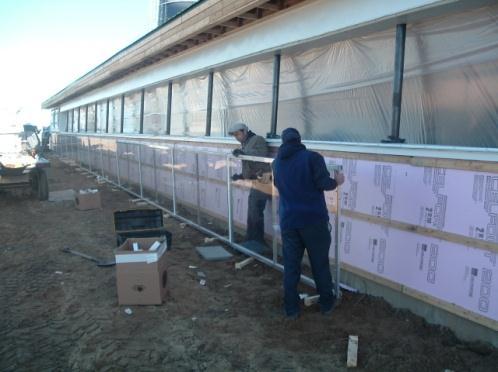
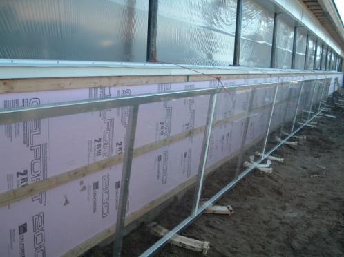
4 PREPARING THE VENTILATION OPENING The installation of the required furring in the periphery of the openings will be executed by the general contractor. The upper furring, the one on the top, will need to be a minimum of 12" high x 2" thick. (12" x 1 ½" finished) (305mm x 38mm); The lateral furring and those at the bottom (lower) will be 2" x 3". (1½" x 2½" finished). (40x60); Be sure to extend the top furring 24" (600mm) to secure the corner pulleys or chain bracket at the extremity chosen for the driving mechanism. Example: A panel section of 24 ft x 4 ft. (7.32m x 1.22m), the finished interior dimension of the opening will be 23-8" x 44.5". (7.22m x 1.13m), Before starting the installation, measure and check the dimensions of the openings on site.
5


 nails or clamps every")
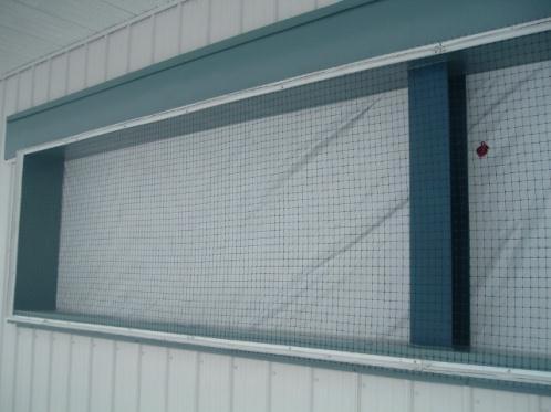
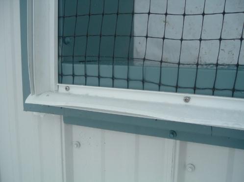
6 INSTALLATION OF THE BIRD SCREEN (OPTIONAL) The installation of the bird screen is optional and selected by the client; It is very important to stretch the screen material before attaching to the wall (see illustration); Nail the screening to the structure with 1 1/4" (31mm) nails or clamps every 6" (150mm).
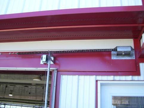
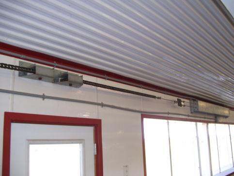
7 INSTALLATION OF LIFTING SYSTEM (PULLEY SYSTEM) EXTERIOR CORNER PULLEY (PC-105) Determine the location of the exterior corner pulley (PC-105) of the lifting system. It needs to be at the far left or right of the ventilation wall. Then, drill a hole to run the master cable. A B DOUBLE PULLEY KIT 5 (127mm) (PC-105) 8- ZINC LAG SCREW 1/4 X 1-1/2 (6mm x 38mm) INTERIOR CORNER PULLEY (PA-105) / (PC-105) Determine the location of the interior corner pulley. o If the ventilation system is manual, the pulley (PA-105) must be installed according to the schematic. o If the ventilation system is automatic, a (PC-105) pulley is needed only if the cable turns 180 deg, i.e. when the actuator is above the ventilation opening, the pulley (PC-105) is needed. It is not required when the actuator is installed perpendicular to the opening (90deg).
8
 (PA-105)")
 AUTOMATIC SYSTEM")
 A DOUBLE")
9 MANUAL SYSTEM A B BRACKET PULLEY KIT 5 (127mm) (PA-105) 8- ZINC LAG SCREW 1/4 X 1-1/2 (6mm x 38mm) AUTOMATIC SYSTEM (IF THE ACTUATOR IS LOCATED ABOVE THE OPENING) A DOUBLE PULLEY KIT 5 (127mm)
10 B 8- ZINC LAG SCREW 1/4 X 1-1/2 (6mm x 38mm)
 previously installed.")
 1- GALV WINCH")

 6- ZINC LAG SCREW 5/16 X 3 (8mm X 76mm) 8- ZINC")
11 MANUAL WINCH To install the manual winch, align the winch with the pulley (PA-105) previously installed. Follow the instructions below. A B C D E F G H 1- WINCH 2500LBS (1135KG) 1- GALV WINCH BRACKET 1- WINCH BRACKET REINFORCEMENT PLATE 3- HEXAGONAL BOLT 3/8"X 1 1/4" (9.52mm x 31.75mm) 3- NYLON LOCK NUT SS304 3/8-16 NC (9.52mm) 6- ZINC LAG SCREW 5/16 X 3 (8mm X 76mm) 8- ZINC LAG SCREW 1/4 X 1-1/2 (6mm x 38mm) 8- ZINC LAG SCREW 1/4 X 1-1/2 (6mm x 38mm)
12 AUTOMATIC ACTUATOR For installing the actuator, it is imperative to determine the height of the master cable and calculate what will be the positioning of the lifting axis. If we raise the canvas with a 1:1 ratio, the center of our actuator (height) will be our lifting axis. If we raise the canvas with a 1:2 ratio, the center of lift will be the top of the master pulley (4KITPOUMAI5) *** Always install the master cable perfectly horizontally to avoid breaking the pulleys *** DETAILS OF ASSEMBLY HARDWARE A B C D E F G H 1- ACTUATOR 4000lbs (1800kg) MODEL 6- ZINC LAG SCREW 3/8 x 2 1/2 (9.52mm x 63.5mm) 1- MASTER PULLEY KIT 5 (127mm) PRE-ASSEMBLED FLEXIBLE MASTER CABLE 3/16 (4.76mm) 7X19 SS PLATE WITH RING TO DOUBLE ACTUATOR RACE 6- ZINC LAG SCREW 5/16 X 3 (8mm X 76mm) 1- DOUBLE PULLEY KIT 5 (127mm) 8- ZINC LAG SCREW 1/4 X 1-1/2 (6mm x 38mm)
13

 MODEL 4-")
 MINIMUM SPACE REQUIRED \"A\": ACTUATOR 48po (1.22m): 15-0\" (4.")
14 Allow enough head space and length on the inner wall to allow the actuator to operate freely without any constraints. *** Always tighten the cable ties supplied with the actuator, double check before use *** A B ACTUATOR 900lbs (400kg) MODEL 4- ZINC LAG SCREW 3/8 x 2 1/2 (9.52mm x 63.5mm) MINIMUM SPACE REQUIRED "A": ACTUATOR 48po (1.22m): 15-0" (4.5m) ACTUATOR 60po (1.52m): 17-0" (5.2m)
15 PULLEY SYSTEM MECHANISM WITH CHAIN BRACKET For the lifting system that you purchased, we offer the option of the lifting system with a chain bracket kit. A 4- ZINC LAG SCREW 5/16 X 2 (8mm X 51mm) B SIMPLE 90D BRACKET WITH PINION C CHAIN #80 D GALV THIMBLE FOR CABLE ¼in (6mm) E CABLE CLAMP 3/16 GALV (4.75MM) F CABLE 3/16 7X19 SS304 G BOLT 5/16" x 1 1/4" (8mm x 31.75mm) H NUTS 5/16po (8mm)

16
17 INSTALLATION OF BRACKETS A) Position and install the pulleys using 5 16"x 2" (8x50mm) wood screws. B) You must respect the opening measurements: align the first bracket at 3/8" (10mm) from the beginning of the opening. C) Position and align the bottom brackets and secure with pulleys and set them using 3/8" diameter x 2 3/4" long (9.5 x 70mm) (Type "W-Jet", flat washer and nut) mechanical anchors. You can use an aluminum guide pipe and your level to align yourself. Note: Depending on the wall type, it is possible that wood or concrete screws will be required instead of mechanical anchors to set the lower brackets. You need to pay special attention if the panels are cut and are of non-standard dimensions. PANEL HEIGHT C D 36" (914mm) 75" (1905mm) 32.5" (825mm) 48" (1.22m) 99" (2515mm) 44.5" (1.13mm) ** THIS IS THE LOCATION OF THE PARTS AT THE EXTREMITIES AND PANEL JOUNTIONS **
18 (SEE NOTES #1, #2 AND #3 ON THE NEXT PAGE) *** NOTE #1: MINIMUM CLEARANCE REQUIRED WITH GROUND LEVEL *** PANEL HEIGHT B 36" (914mm) 44" (1118mm) 48" (1.22m) 56" (1422mm) 60" (1.52m) 68" (1727mm) *** NOTE #2: LOCATIONS OF "U" BRACKET LOCATED IN MIDDLE OF PANEL *** PANEL HEIGHT A 36" (914mm) 4" (102mm) 48" (1.22m) 4" (102mm) 60" (1.52m) 4" (102mm) *** NOTE #3: HEIGHT OF THE FIRST & THE LAST PULLEY *** FOR EACH OF THE OPENINGS / SETS OF PANELS
19
20
21 INSTALLATION OF WEATHERSTRIPPING Note that the elongated tongue is positioned upward to the longitudinal weather-stripping and outside the opening for the vertical weather-stripping. (See details below). Install weather-stripping on the longitudinal and vertical wooden frames of the openings using PAN TEK SS 8-18 X 1 (# 8 x 25mm) SCREWS. Also install two screws on each extremity of the tongue. Cut the weather-stripping at an angle as shown below; CAUTION THE INTERIOR MEASUREMENT BETWEEN THE VERTICAL WEATHERSTRIPPING MUST BE SIMILAR TO THE ONE IN STEP NO 1. Ex: 23-8 "(7.22m).
22

23 WEATHERSTRIPPING INSTALLATION SECTION VIEW
24 PREPARATION OF PANELS AND ASSEMBLY Temporarily remove the panels on the bottom brackets. Handle with care. NOTES: THE PULLEYS WILL BE INSTALLED ONCE THE PANELS HAVE BEEN ASSEMBLED ON THE GUIDE PIPES (alignment facilitated by the grommets).

25
26 GUIDE PIPE INSTALLATION 1. Screw the guide pipe lightly and temporarily to the "U" bracket using 1/4"-20 x 1 1/2" long (# 20 6mm x 38mm) bolts, fender washers and nylon nuts. 2. Insert trough the bottom two aluminum slides. Skip the first upper guide (top) and then the second lower guide (bottom) which 1" (25mm) longer. Do not bolt the aluminum slides to the LEXAN panels during this step. 3. Temporarily mount the guide pipe to the bottom bracket with a 1/4 "-20 x 1 1/2" long (# 20 6mm x 38mm) bolt, flat washer on each side and a Nylon LOCKNUT. 4. Repeat the operations The adjustment and final tightening of the guide pipe should be done later. Note that the lower guide is slightly longer (1" (25mm)) than the upper guide (top).
27 ASSEMBLING THE PANELS a) Manually encase the first panels using the hardware below. b) IMPORTANT: Insert the PVC moulding between the panels (H section). For the first and last panel, use the C section. c) The top and bottom aluminum slides for the guide pipes will be at the junction between two intermediate panels (center). NOTE: (*) If you follow your opening measurements, position the panels immediately at 2 from the opening. The use of a level is strongly recommended. Always install the bottom slide when the panel is in the closed position.

 48\" (1.22m) 72\" (1.")
 DETAILS OF LIFTING PULLEY")
28 STANDARD SS CABLE SIZE FOR YOUR VENTILATION PROJECT PANEL HEIGHT LIFTING CABLE (#5) 36" (914mm) 60" (1.52mm) 48" (1.22m) 72" (1.82mm) 60" (1.52m) 84" (2.13mm) DETAILS OF LIFTING PULLEY ASSEMBLIES
29 INSTALLATION OF LIFTING PULLEYS Once the panels are well inline with the opening and assembled on the bottom brackets: o Install and align the pulleys using the location of the panels lifting grommets. Carefully note the orientation of the drive to properly position the pulley. o Screw the pulleys with 4 - wood screws, 5/16" x 2". Refer to step 4 for the height of the pulley relative to the opening.


30 DETAILS ON THE HARDWARE POSITION *Note that the first and last pulleys of the series are 5.5" from the opening. The other pulleys will be at 5".
31 DETAILS OF POSITIONING OF PULLEYS AND BRACKETS / BEGINNING AND END (front view) DRIVE TO THE LEFT: A = START B = END DRIVE TO THE RIGHT: A = END B = START 1.
32
33 INSTALLATION OF LIFTING CABLES Once the pulleys are installed and the panels assembled: o The 3/16" (4.76mm) flexible master cable diameter should be attached to the lifting system, whether it is a manual winch or automatic actuator; o The flexible cable above must pass through the corner pulleys (PC-105) and/or (PA-105) and be attached to the outside with the rigid master cable. Carefully measure the lengths of cable required so that the solid cable (SS 1/19) does not wrap around the corner pulleys. This would cause it to break. It is the flexible cable (SS 7/19) that must be used for the corner pulleys. o Unroll the master rigid cable and fit it over the lifting pulleys; (Hint: To facilitate the adjustment, temporarily firmly attach the master rigid cable at the end of the opening and tighten the cable with either the manual winch or the actuator. Some people use the last grommet and attach a cable with a cable clamp. o Insert the lifting cable in the lifting grommet. Tie firmly using one cable clamp by creating a slight manual tension without lifting the panel. o Slip the lifting cable in the pulley and firmly attach the master cable beginning with the end opposite the lifting system. Use 2 cable clamps for the master line. o The second lifting cable and the pulley return cable are attached with the same cable clamp on the master line. Lift the wall with the winch or transmission once before proceeding to the next step. NOTE (A) Carefully adjust the lifting grommet during the installation to hide the threads. The grommet must be at its lowest level.
34
35 FINAL ADJUSTMENT o Slowly lift all ventilation panels to full height ("closed" mode) using the winch or actuator. Finish the adjustments until you obtain a compression of the weather-stripping of around 1" (25mm). (See section view below). o Accurately position the guide pipes with an incline of ± 2" (50mm) and complete tightening. o Recheck all bolts on all panels and accessories.

36
37 PARTS LIST / LEXAN PANEL No. Description Item no 1 HEX BOLT SS304 1/4 X 5 (6mm X 127mm) 8BOUHEX145 2 GUIDE PIPE PANEL 1TUYGUID36/48 3 CLEAR PANEL 1 WALL 2LEXAN( ) 4 CABLE SS 1/8 14 /16 (4.27/4.88m) - SPLIT RACE 4CABSS1/ CABLE SS 1/8 - LIFTING CABLE 4CABSS1/8 6 CABLE 1/8 7 X 19 SS304 PI.LI. (250 ROLL) 4CABSS1/ HEX SCREW TEK SS 14 X 1 (25MM) 8VISAUT141H 8 CABLE 3/16 7 X 19 SS304 (4.76MM X 7-19) - FLEXIBLE 4CABSS3/16 9 CABLE 3/16 1 X 19 SS304 (4.76MM X 1-19) - RIGID 4CABSS3/ PULLEY 3 1/2 (89MM) ON BEARING 4PO3.5NBE 11 PITON WITH NUT 5/16 X 3 1/4 (8mm x 83mm) 8PITON5/ CABLE CLAMP 1/8 GALV (3.18MM) 4SERCA1/8G 13 CABLE CLAMP 3/16 GALV (4.75MM) 4SERCA3/16G 14 STOPPER FOR ALUMINIUM CABLE 8ALUMST1/8 15 HEX NUT SS304 3/8 X 2 (50MM) 8BOHEXSS HEX NUT SS 1 1/2 X 1/4-20 (38MM x 6MM) 8BOUHEX NYLON LOCK NUT SS304 1/4-20 NC (6MM) 8ECRNYL1/4 18 NYLON NUT 3/8" (9.52MM) 8ECRNYL3/8 19 WEDGE ANCHOR 3/8 X 2 3/4 (9.52MM X 70MM) 8ENCWEDG23/4 20 FENDER WASHER SS 1/4 X 1-1/4 (6mmx32mm) 8FEWAS1/4 21 FLAT WASHER SS304 ¼ (6MM) 8FW1/4SS 22 ZINC LAG SCREW 5/16 X 2 (8MM X 51MM) 8VIS5/16X2 23 ZINC LAG SCREW 5/16 X 3 (8MM X 76MM) 8VIS5/16X3 24 SCREW SS-304 T.R. 14 X 2- corner pulley (#14 X 51MM) 8VISS214R 25 PAN SCREW TEK SS 8-18 X 1 - weather-stripping (#8 X 25MM) 8VISAUT81PAN 26 WEATHERSTRIPPING NATURAL WIND 90COUPFR 27 SLIDE FOR FLAT BOTTOM 90GLISBASPLAT 28 SLIDE FOR FLAT TOP 90GLISHAUPLAT 29 H SECTION - LEXAN PANEL 1PCH.. 30 LEXAN PANEL CONTOUR 90MUPC1 CONT 31 LEXAN PANEL START 90MUPC1 D 32 LEXAN PANEL END 90MUPC1 F 33 INTERMEDIATE LEXAN PANEL 90MUPC1 I 34 NYLON LOCK NUT 5/16 SS NC 8ECRNY5/16 35 PANN PULLEY BRACKET 2" (51mm) 90POPAN2 36 BRACKET TRIANGLE BOTTOM GALVANISED 90SUPPORTRIAG 37 U BRACKET (GALV) 90SUPPORTUG 38 PULLEY WITH BRACKET AND PANEL CHAIN (KIT) 90KITACCHAINE 39 BIRD SCREEN 3NETLEG65 40 HEX BOLT SS 1 3/4 X 1/4-20 (44.45MM x 6MM) 8BOUHEX14134
INSTALLATION FIXED CANVAS TS100 PULLEY DRIVEN LIFTING SYSTEM
 INSTALLATION FIXED CANVAS TS100 PULLEY DRIVEN LIFTING SYSTEM Ventilation Secco division of Secco International inc. 4040 blvd. Casavant West St-Hyacinthe, Qc J2S 8E3 T: 450-771-0777 F: 450-771-5779 secco@seccointernational.com
JEEVES. JEEVES Installation Manual. Installation Manual The Easiest Do-It-Yourself Dumbwaiter on the Market
 1 888-323-8755 www.nwlifts.com JEEVES Installation Manual The Easiest Do-It-Yourself Dumbwaiter on the Market This manual will cover the installation procedure step-by-step. The installation of this dumbwaiter
ROLLING CURTAIN DOOR INSTALLATION, MAINTENANCE & PARTS MANUAL MODEL 944 WARNING
 ROLLING CURTAIN DOOR INSTALLATION, MAINTENANCE & PARTS MANUAL MODEL 944 WARNING Read manual prior to installing door. Overhead doors are large, heavy objects that move with the help of springs under extreme
Installation Instructions Table of Contents
 Installation Instructions Table of Contents Pre- Installation of Garage Storage Lift 2 Layout the Garage Storage Lift 3 Installing the strut Channels 3 Install the Drive Assembly 5 Install the Drive Shaft
42A FLB WOOD BUNKS 43A FLB ALUMINUM BUNKS ALUMINUM CANTILEVER BOAT LIFT
 Page 1 of 9 42A --- 1265 FLB WOOD BUNKS 43A --- 1265 FLB ALUMINUM BUNKS ALUMINUM CANTILEVER BOAT LIFT Thank you for purchasing our product! Please read these instructions and follow them step by step.*
Durulite Door Hardware Manual
 R Durulite Door Hardware Manual World s Leading Manufacturer Of Traffic Doors Cincinnati, Ohio and Redmond, Oregon Phone: 1-800-543-4455 FAX: 1-800-245-7045 Www.chasedoors.com TABLE OF CONTENTS DESCRIPTION
PORTA-DOCK, INC. 65A 1155 DOUBLE PERSONAL WATERCRAFT LIFT
 Page 1 of 9 PORTA-DOCK, INC. 65A 1155 DOUBLE PERSONAL WATERCRAFT LIFT Thank you for purchasing our product! Please read these instructions and follow them step by step.* STEP 1. Separate and group like
THE AquaBlast & RocketRide FUNSLIDES
 THE AquaBlast & RocketRide FUNSLIDES ASSEMBLY AND INSTALLATION INSTRUCTIONS * * C A U T I O N * * S.R. SMITH AquaBlast TM & RocketRide TM FUNSLIDES TM ARE MANUFACTURED FOR INSTALLATION AND USE ON RESIDENTIAL
MODEL BA735QC. Instruction Manual. Qwik Change Extension Arm
 Instruction Manual FOR BASKETBALL SYSTEMS USING MODEL BA735QC Qwik Change Extension Arm Customer Service (800) 247 7668 P A R T S L I S T Item Qty Description Item Qty Description A 2 4 U-Bolts M 10 3/8
LIGHT DUTY ROLL UP DOOR
 1-800-225-6729 LIGHT DUTY ROLL UP DOOR CAUTION Use proper lifting equipment and correct lifting procedures to avoid damage or injury. MODEL 150C installation guide A rolling door is a large heavy object
Trac-Rite ROLLING CURTAIN DOOR INSTALLATION, MAINTENANCE & PARTS MANUAL WARNING
 Trac-Rite Door, Inc. ROLLING CURTAIN DOOR INSTALLATION, MAINTENANCE & PARTS MANUAL WARNING Read manual prior to installing door. Overhead doors are large, heavy objects that move with the help of springs
\\,, I l- m.. -=_!:~ /20/93 G W-W/O PS SERIES FORD V8-351, :-- REV B FISHER ENGINEERING, ROCKLAD, ME HPS i '&.
 SERIES FORD V8-35,400 977-979 G W-W/O PS PECULIAR HYDRAULICS BELT DRIVE, SLC UNDERHOOD VALVE HPS4504 REV B _\ _C\./,, \\,, \\,,,, ~ ~I :- e l,. i '&. I l- ~~ :-- e l m.. -=_!:~ ~.æ=iiii å FISHER ENGINEERING,
Rollstar Shade Installation Instructions
 Rollstar Shade Installation Instructions All Lifting Systems Inside or Outside Mount Thank you for purchasing your new Rollstar shade. It has been custom-made from the highest quality materials to the
See a picture of each kit on the following page.
 Stainless Steel Chevelle/El Camino Dual Exhaust Kit 793-91325 (2.5 ) or 793-91330 (3.0 ) Fits 1968 1972 Chevelle/El Camino Chevy Small Block/Std Port Heads and Dynatech MuscleMaXX Headers (740-33210, 740-43210
ROLLING CURTAIN DOOR INSTALLATION, MAINTENANCE & PARTS MANUAL WINDLOCK MODEL 955WL WARNING
 ROLLING CURTAIN DOOR INSTALLATION, MAINTENANCE & PARTS MANUAL WINDLOCK MODEL 955WL Read manual prior to installing door. Overhead doors are large, heavy objects that move with the help of springs under
MF 9690, 9790, Challenger 660, 670
 Ag Leader Technology Parts List Note: Indented items indicate parts included in an assembly listed above Quantity by Model Part Name/Description Part No. MF 9690 MF 9790 Challenger 660 Challenger 670 Instruction
Installation Instructions
 DODGE 20K Industry Standard Rail Custom Mounting Kit #2740 Gross Trailer Weight (Maximum)...20,000 lbs. Vertical Load Weight (Max. Pin Weight)...5,000 lbs. SYSTEM TOW CAPACITY Please note, in order to
Installation Instructions. Attention Dealers: Please give this owners manual to the customer when the product is delivered.
 Serving the Truck & Trailer Industry Since 1944 Attention Dealers: Please give this owners manual to the customer when the product is delivered. Call 800-535-9545 www.aeroindustries.com Indianapolis, IN
N. 15th Street, Middlesboro, KY CRUSHED CAR HAULER INSTALLATION INSTRUCTIONS
 1-800-248-7717 1002 N. 15th Street, Middlesboro, KY 40965 CRUSHED CAR HAULER INSTALLATION INSTRUCTIONS Congratulations on your purchase of a Mountain Tarp Crushed Car Hauler tarping system. With tarping
G: OS/27/ R30, V30/ R3S/V3S W/3S0 FISHER ENGINEERING, ROCKLAD, ME SUBJECT TO CHAGE PECULIAR HYDRAULICS HPS4S71
 CHEV/GMC V8-30S,3S0 V6-4.3L W/O AC BLAZER, JIMMY, SUB W/3S0 R30, V30/ R3S/V3S W/3S0 986-87 986-87 988 988- PECULIAR HYDRAULICS HPS4S7 BELT DRIVE, SLC UNDERHOOD VALVE 3i -INSTALL THRU ENGINE LIFT HOOK ~
Easy Cover. Installation Instructions. Attention Dealers: Please give this owners manual to the customer when the product is delivered.
 Serving the Truck & Trailer Industry Since 944 Easy Cover Attention Dealers: Please give this owners manual to the customer when the product is delivered. Call 00-3-94 www.aeroindustries.com Indianapolis,
Page: REV 3: Add drill and tap information to Figure 4 DRILL #3, TAP 1/4-28 BOTH ENDS.
 REVISION DESCRIPTION: 1) Page: 32-03 MEMO: Step 4 should not be bold. Fix WD-1213 callout in Figure 3. Page: 32-04 REV 3: Add drill and tap information to Figure 4 DRILL #3, TAP 1/4-28 BOTH ENDS. Add make
K B J K A C H D E I F. Single and Bi-Parting Electric Sliding Doors with Automatic Operator (ICC-5) Parts List. R-PLUS Cold Storage Doors
 Parts List. R-PLUS Cold Storage Doors") Single and Bi-Parting Electric Sliding Doors with Automatic Operator (ICC-) Parts List K B J K A C H G Release Date: -0 D E R-PLUS Cold Storage Doors NE 9th Portland, Oregon 90 Toll Free () 0-99 Fax (0)
Single and Bi-Parting Electric Sliding Doors with Automatic Operator (ICC-) Parts List K B J K A C H G Release Date: -0 D E R-PLUS Cold Storage Doors NE 9th Portland, Oregon 90 Toll Free () 0-99 Fax (0)
USER'S MANUAL and INSTALLATION GUIDE
 AM Inlet Series 8" and 2" baffle AM0896GS AM296GS USER'S MANUAL and INSTALLATION GUIDE TABLE OF CONTENTS Section Page...Requirements for Installation...2 2...Unpacking the AirManager... 3-5...Exploded
ProPass-200 Top Dresser
 Setup Manual Form No. 3365-184 Rev A ProPass-200 Top Dresser Model No. 44700-Serial No. 310000001 and Up Model No. 44701-Serial No. 310000001 and Up Model No. 44704 Model No. 44705 Model No. 44706 Model
Installation Instructions
 DODGE 20K Industry Standard Rail Custom Mounting Kit #2742 Gross Trailer Weight (Maximum)...20,000 lbs. Vertical Load Weight (Max. Pin Weight)...5,000 lbs. SYSTEM TOW CAPACITY Please note, in order to
MASTER CYLINDER INSPECTION
 7-16 CHASSIS A-PDF Split DEMO : Purchase from www.a-pdf.com to remove the watermark Remove the piston assembly. MASTER CYLINDER INSPECTION MASTER CYLINDER Inspect the master cylinder bore for any scratches
Continuous Cord Loop Designer Series Roller Shades
 Shade Maintenance Leveling a Crooked Shade 1. Pull down shade until roller is exposed. Do not pull further to avoid pulling cloth off roller. 2. Stick a 5" strip of masking tape into the roller at opposite
Shaver Industries. Assembly Instructions Spring Assist Vertical Vinyl Curtain Door Projection Mount
 Shaver Industries 20 Steckle Place, Kitchener, ON N2E 2C3 Ph 1(888) 766 8328 www.shaverinc.com Assembly Instructions Spring Assist Vertical Vinyl Curtain Door Projection Mount Valued Shaver Customer: We
Glossary. Cable Clamps A manufactured device used to secure two pieces of cable to each other. Size of clamp is determined by the cable diameter.
 Glossary A Cable Clamps A manufactured device used to secure two pieces of cable to each other. Size of clamp is determined by the cable diameter. A-Frame Support member used to fasten torsion spring assembly
Installation Manual. For. PWC 3000 Boat Lifts
 Installation Manual For PWC 3000 Boat Lifts Page 2 Safety Precautions 1. Your boat lift is a heavy duty piece of equipment. It is important that all persons that may operate this unit have read and understood
AmTryke Adult Recumbent Model HP1000 #50-HC-1000
 AmTryke Adult Recumbent Model HP1000 #50-HC-1000 TOOLS Needed for Assembly 5 mm Allen Wrench 8 mm Socket or Wrench 10 mm Socket or Wrench 14 mm Socket or Wrench 15 mm Socket or Wrench 22 mm Socket or Adjustable
R O A D S M I T H TRIKE CONVERSIONS BY THE TRIKE SHOP
 R O A D S M I T H TRIKE CONVERSIONS BY THE TRIKE SHOP Please thoroughly review the instructions before and during installation. Keep in mind that this product was designed to be installed by trained dealer
MOTORIZED INSTALLATION INSTRUCTIONS
 MOTORIZED Mega-Pro Swinging Doors Motorized Accordion Strip Doors INSTALLATION INSTRUCTIONS Save-T Roll-Up Bug Screen Save-T Vinyl Roll-Up Screen Save-T Guard Security Gates Save-T Flex-Guard Chain Link
GPS AutoSteer System Installation Manual
 GPS AutoSteer System Installation Manual Supported Vehicles Agco Gleaner Combines R65 R66 R75 R76 PN: 602-0288-01-A LEGAL DISCLAIMER Note: Read and follow ALL instructions in this manual carefully before
R O A D S M I T H TRIKE CONVERSIONS BY THE TRIKE SHOP
 R O A D S M I T H TRIKE CONVERSIONS BY THE TRIKE SHOP Please thoroughly review the instructions before and during installation. Keep in mind that this product was designed to be installed by trained dealer
~~ " '" :.~ ~. -~ :: ø U) 6Â~ l\ '---_._ , " ~ -1rr-~.." fj PECULIAR HYDRAULICS. " f ',~, ...
 6Â~ l\ '---_._ , ~ -1rr-~.. fj PECULIAR HYDRAULICS. f ',~, ...") FORD V8-30, 35 W-W/O AC 988-99 PECULIAR HYDRAULICS BELT DRIVE, SLC UNDERHOOD VALVE ~. _ Ln c. " f 000000 HPS59 REV. E, ~ ~~ " '" --- -. ',~, ~ -rr-~.." fj..-:.~ ~.&I C/~.. ""Q ic ø ~. -~ :: ø U) c: ::
FORD V8-30, 35 W-W/O AC 988-99 PECULIAR HYDRAULICS BELT DRIVE, SLC UNDERHOOD VALVE ~. _ Ln c. " f 000000 HPS59 REV. E, ~ ~~ " '" --- -. ',~, ~ -rr-~.." fj..-:.~ ~.&I C/~.. ""Q ic ø ~. -~ :: ø U) c: ::
Additional Instructions for 6" Drop
 Serving the Truck & Trailer Industry Since 1944 Additional Instructions for 6" Drop Attention Dealers: Please give this manual to the customer when product is delivered. Call 800-535-9545 www.aeroindustries.com
\ \ ~, en ~ \ \\ en I- ( \\\ b3~(i 5/27/93. æ Lr PECULIAR HYDRAULICS W LL BELT DRIVE, SLC,
 DODGE V8-38\360 W-W/O AC W/SERPENTINE 99-9 PECULIAR HYDRAULICS BELT DRIVE, SLC, UNDERHOOD VALVE 7505 ~., ( \\\ \ \\ ~,/./ LL a: :: z en ~ en I- W LL æ Lr ~,. \ \ \ "',: e /' ~ '\ '- -- - /' "-.. -- - -..
PORTA-DOCK, INC. 100A 1284 ALUMINUM CANTILEVER BOAT LIFT
 Page 1 of 7 PORTA-DOCK, INC. 100A 1284 ALUMINUM CANTILEVER BOAT LIFT Thank you for purchasing our product! Please read these instructions and follow them step by step. * STEP 1. Separate and group like
Contents. Section 5: Adjustments Ball Detect Adjustment Transport Band Tension Adjustment
 Contents Section 5: Adjustments... 5-3 1. Ball Detect Adjustment... 5-3 2. Transport Band Tension Adjustment... 5-5 3. Transport Band Drive Belt Tension Adjustment... 5-7 4. Ball Cushion Adjustment...
MINI BIKE-2016 MB 200 Set-up Instruction
 MINI BIKE-2016 MB 200 Set-up Instruction 2016-06-01 1. Install rear shocks: open the crate and install the rear shocks with bolt M10x1.25x40 and self-locking nut M10x1.25. The requested torque is 37-44N.m
Owner smanual. Banks Ram-Air Super-Scoop Chevy/GMC 6.6L Duramax Turbo-Diesel Pickups. with Installation Instructions
 with Installation Instructions Owner smanual Banks Ram-Air Super-Scoop 2003-07 Chevy/GMC 6.6L Duramax Turbo-Diesel Pickups THIS MANUAL IS FOR USE WITH KITS 42168 and 42169 Gale Banks Engineering 546 Duggan
Section 5: Parts Replacement
 Section 5: Parts Replacement Should the STAR TRAC 4500 Treadmill experience a problem requiring replacement of a specific part, the following procedures will help and instruct in the replacement of major
Cincinnati, Ohio and Redmond, Oregon Phone: Fax:
 Durulite Retailer Hardware Manual Durulite Retailer Hardware Manual World s Leading Manufacturer Of Traffic Doors Cincinnati, Ohio and Redmond, Oregon Phone: 1-800-543-4455 Fax: 1-800-245-7045 www.chasedoors.com
Bruce s Science workbench
 Baby Vandegraff Generator by Bruce Yeany 2001 https://www.youtube.com/watch?v=parq01q DKe4 http://www.instructables.com/id/van-de- Graaff-Electrostatic-High-Voltage- Generator/ https://www.youtube.com/watch?v=esz
Outload Trough Roller Conveyor
 Outload Trough Roller Conveyor OWNER'S MANUAL 00003400 (8/99) Table of Contents Warranty Information.............................. Inside Front Cover Operator Qualifications / Sign Off Sheet..............................
TOYOTA VENZA 2009 TRAILER WIRE HARNESS Procedure
 Part Number: PT791-0T099 Kit Contents Item # Quantity Reqd. Description 1 1 Trailer Wire Harness Module 2 1 4-Flat Harness 3 1 Battery Power Wire Harness 4 1 Mounting Bracket, 4-Flat 5 2 Screw #10-24 6
Materials List: Tools List:
 Materials List: Anchor assembly Automated power supply Automated power supply hardware packet Automation bracket assembly Automation bracket assembly hardware packet Automation winch assembly Cable Cable
AmTryke Adult Recumbent Model JT2000 #50-FC-2000
 AmTryke Adult Recumbent Model JT2000 #50-FC-2000 TOOLS Needed for Assembly 5 mm Allen Wrench 8 mm Socket or Wrench 10 mm Socket or Wrench 14 mm Socket or Wrench 15 mm Socket or Wrench 22 mm Socket or Adjustable
PORTA-DOCK, INC. 100A 1200 LB. 84 WIDE ALUMINUM CANTILEVER BOAT LIFT 102A 1200 LB. 113 WIDE ALUMINUM CANTILEVER BOAT LIFT
 Page 1 of 7 PORTA-DOCK, INC. 100A 1200 LB. 84 WIDE ALUMINUM CANTILEVER BOAT LIFT 102A 1200 LB. 113 WIDE ALUMINUM CANTILEVER BOAT LIFT Thank you for purchasing our product! Please read these instructions
INSTALLATION & OWNER S MANUAL
 Rev. B, p. 1 of 25 INSTALLATION & OWNER S MANUAL POLARIS RANGER RCS (for models XP or HD) (for model years 2009-) cab without doors kit (p/n 1POLRCWD) cab with doors kit (p/n 1POLRC) doors only kit (p/n
Installation Instructions Models 2858, 2858A-1, 2858GL February 2009
 Installation Instructions Models 2858, 2858A-1, 2858GL February 2009 www.donovan-ent.com Donovan Enterprises 3353 SE Gran Park Way Stuart, FL 34997 800-327-8287 Step 1 Head Assembly Installation Instructions
Installation Instructions
 DODGE 24K Industry Standard Rail Heavy Duty Custom Mounting Kit #2230 Gross Trailer Weight (Maximum)...24,000 lbs. Vertical Load Weight (Max. Pin Weight)...6,000 lbs. SYSTEM TOW CAPACITY Please note, in
MIC210 Electric Farm Conversion Instructions
 MIC210 Electric Farm Conversion Instructions Note: Apply the supplied Dielectric Lubricant to all wire connections when each wire is hooked up. The Dielectric Lubricant will help to prevent corrosion.
Factory Five Racing, Inc. 818 Kit Assembly manual revision 1i update
 Factory Five Racing, Inc. 818 Kit Assembly manual revision 1i update Pedal box...1 Cable Accelerator Pedal (2002-2005)...2 OEM seats...7 Windshield... 13 Center console... 19 Pedal box Attach the pedal
Top Down Rollstar Shade Installation Instructions
 Top Down Rollstar Shade Installation Instructions Thank you for purchasing your new Rollstar shade. It has been custom-made from the highest quality materials to the dimensions you specified. With proper
Shaver Industries. Assembly Instructions Spring-Assist Vertical Vinyl Curtain Door
 Shaver Industries 20 Steckle Place, Kitchener, ON N2E 2C3 Ph 1(888) 766 8328 www.shaverinc.com Assembly Instructions Spring-Assist Vertical Vinyl Curtain Door System Overview: Your Shaver's Spring-Assist
2005 Toyota Truck RAV4 2WD L4 2.4L (2AZ FE)
") 2005 Toyota Truck RAV4 2WD L4 2.4L (2AZ FE) Vehicle» Engine, Cooling and Exhaust» Engine» Timing Chain» Service and Repair TIMING CHAIN TIMING CHAIN http://alldatapro.com/alldata/pro~v440713400~c39519~r0~od~n/0/108596970/110859775/110859788/110859790/34853741/100411974/34853743/56492475
2005 Toyota Truck RAV4 2WD L4 2.4L (2AZ FE) Vehicle» Engine, Cooling and Exhaust» Engine» Timing Chain» Service and Repair TIMING CHAIN TIMING CHAIN http://alldatapro.com/alldata/pro~v440713400~c39519~r0~od~n/0/108596970/110859775/110859788/110859790/34853741/100411974/34853743/56492475
LSP inc. READ CAREFULLY - FAILURE TO FOLLOW INSTRUCTIONS AND SAFETY RULES MAY RESULT IN SERIOUS INJURY
 LSP inc. Canopy Frame Owner s Manual LS1507 side tube bundle 18' LS1508 bow bundle LS1509 accessory box 18' LS1514 side tube bundle 20' LS1515 bow bundle LS1516 accessory box 20' LS1601 side tube bundle
~~ / ~ ~ ~) \.~ I 00 \ 'i \ ~/~ \ vi 'I I.. iii I ~ \ ~ i ~ I. \ \ i / I \ III / 1/ " ~ ~ ~,I. /1 &) \\:~.- , / . \ /,/ '\.
 \.~ I 00 \ 'i \ ~/~ \ vi 'I I.. iii I ~ \ ~ i ~ I. \ \ i / I \ III / 1/ ~ ~ ~,I. /1 &) \\:~.- , / . \ /,/ '\.") FORD 7. 3L DIESEL W/O AC V-BELT 99-9 PECULIAR HYDRAULICS BELT DRIVE, SLC UNDERHOOD VALVE 750.. ca. ~e ~!~ 'i \ ~t;. - / \, I \ / &) \\:~.- i -~---7 \ ~~ / '/ ~ I~ I I ~ i ~ I ~~ ~ ~ ~) i _-,I.. ~ ~ ~,I.
FORD 7. 3L DIESEL W/O AC V-BELT 99-9 PECULIAR HYDRAULICS BELT DRIVE, SLC UNDERHOOD VALVE 750.. ca. ~e ~!~ 'i \ ~t;. - / \, I \ / &) \\:~.- i -~---7 \ ~~ / '/ ~ I~ I I ~ i ~ I ~~ ~ ~ ~) i _-,I.. ~ ~ ~,I.
PW Cantilever Lift: Part Number: Instructions and Safety Tips 1200 Ibs Capacity
 www.shoremaster.com 1200 PW Cantilever Lift: Part Number:1017507 Instructions and Safety Tips 1200 Ibs Capacity 1. 2. 3. 4. 5. CAUTION - PUT SAFETY FIRST Before attempting to install or operate this hoist,
Passenger/Right Side Frame Bracket. Driver/Left Side Frame Bracket. (4) Spacer Washers. (2) Bull Bar Mounting Brackets
 Spacer Washers. (2) Bull Bar Mounting Brackets") PARTS LIST: 1 Bull Bar 12 s 1 Driver/Left Frame Mounting Bracket 1 Passenger/Right Frame Mounting Bracket 6 10mm Lock Washers 2 Bull Bar Mounting Brackets 6 10mm Hex Nuts 4 Large Spacer Washers 4 8-1.25mm
PARTS LIST: 1 Bull Bar 12 s 1 Driver/Left Frame Mounting Bracket 1 Passenger/Right Frame Mounting Bracket 6 10mm Lock Washers 2 Bull Bar Mounting Brackets 6 10mm Hex Nuts 4 Large Spacer Washers 4 8-1.25mm
Installation Manual. For. Alumavator and Platinum. Vertical Installation. Elevator Boat Lifts
 Installation Manual For Alumavator and Platinum Vertical Installation Elevator Boat Lifts Page 2 Safety Precautions 1. Your boat lift is a heavy duty piece of equipment. It is important that all persons
INSTALLATION MANUAL. Thunderstone Manufacturing LLC 3400 West O Street Lincoln, NE (Fax)
") INSTALLATION MANUAL August 7 th 2018 43 /48 /50 2011 and Older Timpte STD/Split 36 Style Hopper Trailers with Roller Bearing Doors Kit #101533 for 96w & Kit #101534 for 102w Thunderstone Manufacturing
INSTALLATION MANUAL August 7 th 2018 43 /48 /50 2011 and Older Timpte STD/Split 36 Style Hopper Trailers with Roller Bearing Doors Kit #101533 for 96w & Kit #101534 for 102w Thunderstone Manufacturing
/ i I ~~. $.. -- ~ :: ( : \~ l-i ~ I. / n i ~ * Jij_ / 62Qo 5/29/91 ~ (. \ \ \ \ ~ h: ~ G W/O AC ~~ ~ \ \ \ \ / _J PECULIAR HYDRAULICS
 ; c. SERIES FORD V8-460 G W/O AC 1983-1987 PECULIAR HYDRAULICS. BELT DRIVE, SLC UNDERHOOD VALVE HPS4551 REV C / / _J- - \ \ \ \ \ \ \ \ \ /) ~ ii / io~. \i / i I / n i \~ l-i ~ I Jij_ / i I / ~ :: ~ (.
C15C C15C. Page 1 of 20
 2 x Lid Front Hinge 1135 8 x M8 Bolt 8 x M8 Washer (3mm Thick) 4 x M6 Large washers 4 x M6 Spring washers 4 x M6 x 40mm Bolts 6 x M6 20mm Bolts 6 x M6 Washers 20 x Screws 2 x Lid mount gas strut bracket
PFadvantage Metalfor Araus 1360
 Metalfor Araus 1360 Note: Indented items indicate parts included in an assembly listed above Part Name/Description Part Number Quantity Instruction Kit Metalfor Araus 2005300-14 1 Display Bracket 4000134
FARM MODEL INSTALLATION INSTRUCTIONS
 REAR ATTACHMENT ELECTRIC CONVERSION FARM MODEL INSTALLATION INSTRUCTIONS This page intentionally left blank MICHEL S INDUSTRIES, LTD. p.o. Box 119 St. GREGOR,SK PH: 306.366.2184 em: SALES@MICHELS.CA 1
Opening Quality Doors Around The World. Installation Instructions Bi-Parting Freight Doors - Q Style (Power and Manual)
") Opening Quality Doors Around The World www.couriondoors.com Installation Instructions Bi-Parting Freight Doors - Q Style (Power and Manual) Table of Contents For Immediate Help Call 1-800-533-5760 Q Style
Opening Quality Doors Around The World www.couriondoors.com Installation Instructions Bi-Parting Freight Doors - Q Style (Power and Manual) Table of Contents For Immediate Help Call 1-800-533-5760 Q Style
FLOODLIGHT unit IMPORTANT WARNING! RRAC055/RRAC059. INSTALL TIME: 30 mins
 LED 4" FLOODLIGHT unit RRAC055/RRAC059 INSTALL TIME: 30 mins Depending on the type of installation chosen, not all components supplied will be used. Refer to Page 13 Section 7 on how to set the angle of
(2) 12mm x 40mm Short Low Profile Bolt Plates. (2) Spacer Washers. (4) 12mm Plastic Retainers. Passenger/Right Front.
 12mm x 40mm Short Low Profile Bolt Plates. (2) Spacer Washers. (4) 12mm Plastic Retainers. Passenger/Right Front.") PARTS LIST: 1 Driver/Left Running Board with 1 Rubber Backing (use on SX & Limited models) 4 12mm Plastic Retainer 1 Passenger/Right Running Board with 1 Rubber 4 12mm Lock Washer Backing (use on SX &
PARTS LIST: 1 Driver/Left Running Board with 1 Rubber Backing (use on SX & Limited models) 4 12mm Plastic Retainer 1 Passenger/Right Running Board with 1 Rubber 4 12mm Lock Washer Backing (use on SX &
\ -:~ \ C) '".. ~., n ~ 1I:I (: II :I PECULIAR HYDRAULICS OS/27/93 FISHER ENGINEERING, ROCKLAD, ME SUBJECT TO CHAGE
 '.. ~., n ~ 1I:I (: II :I PECULIAR HYDRAULICS OS/27/93 FISHER ENGINEERING, ROCKLAD, ME SUBJECT TO CHAGE") DODGE V8-38 & 360 W-W/O AC, SB ALT L ( Q.... :: ~ 97-988 PECULIAR HYDRAULICS BELT DRIVE, SLC, UNDERHOOD VALVE C) '".. z == aa _ :: I:I (: II :I Uo''' w. -- c: øø C- HPS457 REV. B ~~ ê-q ê;?j~. \ -:~ \
DODGE V8-38 & 360 W-W/O AC, SB ALT L ( Q.... :: ~ 97-988 PECULIAR HYDRAULICS BELT DRIVE, SLC, UNDERHOOD VALVE C) '".. z == aa _ :: I:I (: II :I Uo''' w. -- c: øø C- HPS457 REV. B ~~ ê-q ê;?j~. \ -:~ \
Driver/left Corner Fill Panel. Passenger/Right Corner Fill Panel Left and Right Bar Light L Brackets. (2) Plastic Plugs. License Plate Bracket
 Plastic Plugs. License Plate Bracket") LD1 FRONT BUMPER PART#R102615 R102618 PARTS LIST: 1 LD1 Bumper Assembly 8 10mm Lock Washers 1 Driver/left Frame Mounting Bracket 8 10mm Hex Nuts 1 Passenger/right Frame Mounting Bracket 2 8-1.25mm x 25mm
LD1 FRONT BUMPER PART#R102615 R102618 PARTS LIST: 1 LD1 Bumper Assembly 8 10mm Lock Washers 1 Driver/left Frame Mounting Bracket 8 10mm Hex Nuts 1 Passenger/right Frame Mounting Bracket 2 8-1.25mm x 25mm
Installation Instructions February 2009
 Installation Instructions February 2009 www.donovan-ent.com Donovan Enterprises 3353 SE Gran Park Way Stuart, FL 34997 800-327-8287 The Hammer Head Assembly Installation Instructions (Rollerbar & Direct
Mounting SySteMS ApplicAtionS overview version 1.2 March 2013
 Mounting Systems Applications Overview Version 1.2 March 2013 tritec Mounting Systems: Applications Overview I. Pitched Roof: Roof-Top 1. Tiles, shingles and corrugated panels 1.1 TRI-STAND on tiles 1.1.1
INSTALLATION & OWNER S MANUAL
 Rev. C p. 1 of 21 INSTALLATION & OWNER S MANUAL F5205 HARD SIDED CAB KIT INSTALLATION & OWNER S MANUAL The contents of this envelope are the property of the owner. Be sure to leave with the owner when
Installation Manual. For. High Speed Alumavator and Platinum. 10 and 23 Degree. Elevator Boat Lifts
 Installation Manual For High Speed Alumavator and Platinum 10 and 23 Degree Elevator Boat Lifts Page 2 Safety Precautions 1. Your boat lift is a heavy duty piece of equipment. It is important that all
Honda Pioneer 1000 Turn Indicator Kit
 Honda Pioneer 1000 Turn Indicator Kit Thank you for purchasing XTC Power Products Turn Signal System. Our Turn System is unique from the other kits on the market. Our Kit is plug and play with only power
WARNING. When installed in accordance with these instructions, the front protection bar does not affect operation of the SRS airbag.
 Part Number: 343870 F/Kit 17557 Product Deluxe Combination Winch and Non Winch Bull Bar Description: Suited to Nissan XTERRA 05ON USA Only vehicle/s: WARNING REGARDING VEHICLES EQUIPPED WITH SRS AIRBAG;
Assembly Instructions
 Assembly Instructions Part Number Description Model Approx. Assembly Time 99994-0903 Windshield Wiper Kit Mule SX 1 Hour WARNING Improper installation of this accessory could result in an accident causing
w w w. h d o n l i n e s h o p. d e ELECTRA-GLO LIGHT BARS GENERAL INSTALLATION -J04723 REV Kit Number Models Kit Contents
 -J07 REV. 00-0-0 GENERAL Kit Number -09 Models For model fitment information, see the P&A Retail Catalog or the Parts and Accessories section of www.harley-davidson.com (English only). Kit Contents See
MECHANICAL INSTALLATION PROCEDURES for Custom Grids and Support Framing
 CosaTron Mechanical Installation Instructions MECHANICAL INSTALLATION PROCEDURES for Custom Grids and Support Framing BECAUSE CLEAN AIR MATTERS General The CosaTron Custom Grids are located within the
Combine Cover Manual
 Combine Cover Manual Installation Instructions Page 27 Operating Instructions Page 8 Warranty Page 8 Trouble Shooting Page 9 11 For Model s: Case I.H. 2388, 2188, 1688 and 1680 With a MAURER Hopper Extension
Installation, Operating Instructions and Replacement Parts Installation video available at
 Installation, Operating Instructions and Replacement Parts Installation video available at www.kool-shield.com/support/ Made in the USA By Humboldt Specialty Manufacturing Co. www.kool-shield.com Revision
N. 15th Street, Middlesboro, KY TARP-N-GO SYSTEMS INSTALLATION INSTRUCTIONS
 1-800-248-7717 1002 N. 15th Street, Middlesboro, KY 40965 TARP-N-GO SYSTEMS INSTALLATION INSTRUCTIONS Congratulations on your purchase of a Mountain Tarp Tarp-N-Go tarping system. With tarping systems
GENUINE PARTS INSTALLATION INSTRUCTIONS
 GENUINE PARTS INSTALLATION INSTRUCTIONS DESCRIPTION: APPLICATION: PART NUMBER: Electronic Tailgate Lock Kit Nissan Titan 999M2-W3005 KIT CONTENTS: Item Qty. Part Description Service Part Number A 1 Electronic
ST 93 RIPPER INSTALL KIT
 ST 93 RIPPER INSTALL KIT P/N 2883777;2883778;2883779 APPLICATION The Timbersled Ripper ST93 Install Kit is designed to fit all Timbersled ST90 and ST93 Ripper models. This includes; Timbersled Model No.
Shaver Industries. Assembly Instructions Vertical Vinyl Curtain Door DT2 Wire Rope Replacement
 Shaver Industries 20 Steckle Place, Kitchener, ON N2E 2C3 Ph 1(888) 766 8328 www.shaverinc.com Assembly Instructions Vertical Vinyl Curtain Door DT2 Wire Rope Replacement Overview: Preparation: Installation:
Fast Master Products, Inc. P.O. Box 654, Katy Texas Tel: (281) Fax: (281)
 Fax: (281)") Fast Master Products, Inc. P.O. Box 654, Katy Texas 77492-0654 Tel: (281) 391-6750 Fax: (281) 391-6760 Email: info@cruiserlift.com Easy installation and removal from the pick-up bed. Compatible with all
Fast Master Products, Inc. P.O. Box 654, Katy Texas 77492-0654 Tel: (281) 391-6750 Fax: (281) 391-6760 Email: info@cruiserlift.com Easy installation and removal from the pick-up bed. Compatible with all
INSTALLATION INSTRUCTIONS
 TABLE OF CONTENTS GENERAL...2 SPECIFICATIONS...2 PACKAGE CONTENTS...2 PACKAGE CONTENTS: ACCESSORIES...3 REQUIRED TOOLS...3 ADD-ON COMPONENTS...3 CABINET MOUNTING HAND-HOLE OR VAULT...3 CABINET MOUNTING
1989 Jeep Cherokee. STEERING COLUMN' '1989 STEERING Jeep Steering Columns STEERING COLUMN STEERING Jeep Steering Columns
 STEERING COLUMN 1989 STEERING Jeep Steering Columns DESCRIPTION All models use collapsible steering columns. All columns have integral ignition switch and locking device. Optional tilt wheel is available
INSTALLATION INSTRUCTIONS
 INSTALLATION INSTRUCTIONS REAR DISC CONVERSION KIT A126-2 1988-98 C1500 2WD 10" REAR DRUM Thank you for choosing STAINLESS STEEL BRAKES CORPORATION for your braking needs. Pleases take the time to read
Automatic Roof Hatch Opener
 Automatic Roof Hatch Opener Installation Guide REQUIRED TOOLS (These tools are required to complete the installation) Cordless Drill 1/8 1/4 Drill Bits 1/8 Pin Punch #2 Philips Bit Rachet Sharpie Hammer
'99-03 CHEVROLET/GMC IFS 4WD 6" SUSPENSION SYSTEM P/N INSTALLATION INSTRUCTIONS
 1/16/04 '99-03 CHEVROLET/GMC IFS 4WD 6" SUSPENSION SYSTEM P/N. 10-41099 INSTALLATION INSTRUCTIONS NOTE: Each Lift Kit and options to Lift Kits are packaged separately. Therefore, installation procedures
SERIES B & C ROLLER DOORS INSTALLATION GUIDE
 SERIES B & C ROLLER DOORS INSTALLATION GUIDE THESE INSTRUCTIONS ARE PROVIDED FOR USE BY EXPERIENCED INSTALLERS OF GARAGE DOORS BY UNDERTAKING THE INSTALLATION OF THIS DOOR, THE INSTALLER UNDERSTANDS THE
Part Name/Description Part Number Quantity Instruction Kit Metalfor Flow Sensor
 NOTE: Indented items indicate parts included in an assembly listed above Part Name/Description Part Number Quantity Instruction Kit Metalfor 4101091 1 Flow Sensor 4001356 1 Deflector plate 2000612-1 1
INSTALLATION & OWNER S MANUAL
 Rev. C, p. of 2 INSTALLATION & OWNER S MANUAL KUBOTA B2650/3350 Hard Sided Cab p/n KB33AS Soft Sided Cab p/n KB33SS Installation Instructions The contents of this envelope are the property of the owner.
Go-ped ESR750 / ESR750EX Rear Brake Installation Instructions
 Go-ped ESR750 / ESR750EX Rear Brake Installation Instructions This kit provides all the parts you need to install a rear brake on your ESR750 or ESR750EX. It will not work on an ESR Sport, or other Go-ped
Start-up and Operation
 Start-up and Operation NEVER FORGET THAT ANY MACHINE CAN BE VERY DANGEROUS WHEN NOT OPERATED CORRECTLY AND SAFELY. ALWAYS VISUALLY CHECK TO MAKE SURE THAT ALL PERSONS ARE CLEAR BEFORE TURNING ON ANY CONTROLS.