Dynamic Propeller Balancing Using the Model 1015 ProBalancer Sport. Product Support ACES Systems/TEC Aviation Division
|
|
|
- Gervase Hunter
- 5 years ago
- Views:
Transcription

1 Dynamic Propeller Balancing Using the Model 1015 ProBalancer Sport Product Support ACES Systems/TEC Aviation Division
2 Goals for This Training Understand Basics of Vibration Understand the Benefits of Balancing Understand the Fundamentals for using the ProBalancer Sport for Dynamic Propeller Balancing
3 Overview The Basics of Vibration Definition Why it happens How the ProBalancer Sport measures it How we correct it
4 The Basics of Vibration Definition Vibration is defined as: mechanical oscillation about an equilibrium point. For the purpose of Propeller Balance, vibration can be described as: the unwanted, unproductive, cyclic oscillation of the propeller and engine assembly about its rotational axis.
5 The Basics of Vibration Remember All noise and/or vibration is not generated by an imbalance in the propeller. To verify the vibration source, a vibration survey should be conducted and manufacturers limitations adhered to.
6 The Basics of Vibration Why Does It Happen? When the weight of a rotating propeller and engine assembly is not equally distributed, the dominant or heavy point attempts to continue moving in a straightline. The resulting force attempts to pull the assembly outside its rotational axis. The assembly then orbits what would be the normal center of rotation, causing vibration.
7 The Basics of Vibration Vibration-Related Complaints Cracked exhaust stacks and sheet metal Higher than normal occurrence of engine and prop oil leaks and light bulb failures Physical movement of airframe (buzz in the seat, yoke, rudder pedals) Malfunctioning or failed avionics Passenger complaints of noise in the cabin
8 The Basics of Vibration Examples of the Effects of Vibration Vibration excites natural frequencies in other components throughout the airframe and engine assemblies. The expended energy from vibration causes wear of components, reduced performance, and passenger discomfort.
9 The Basics of Vibration How the ProBalancer Sport Measures Sensor Type Sensor Engineering Unit Characteristics of the Sensor Sensor Specifications Sensor Mounting Vibration
10 The Basics of Vibration How It Is Measured The vibration sensor generates a small voltage when the mass compresses the piezoelectric element. That voltage is proportional to the force being exerted on the element.
11 The Basics of Vibration How It Is Measured Sensor Type The ProBalancer Sport uses an accelerometer to measures the rate of change of velocity with time. Engineering Unit gs (equivalent gravities) -acceleration
12 The Basics of Vibration How It Is Measured Sensor Characteristics Accelerometers Measure Acceleration Typically Reported in g s More Sensitive to Higher Frequencies Directly Related to Force Caused by Unbalance Used in Balancing (after conversion to velocity or displacement)
13 The Basics of Vibration How We Correct It Improve manufacturing methods Remove and replace defective components Static Balance Static Balance + Dynamic Balance
14 Overview Understanding the Benefits of Balancing The negative effects of vibration How balancing effects service life and economy of operation
15 The Benefits of Balancing Reduces: Noise Vibration Airframe damage Avionics damage Fatigue and stress on passengers Increases: Economy of operation Service life of airframe and components Comfort
16 Overview Fundamentals for using the ProBalancer Sport for Dynamic Propeller Balancing When to balance Required equipment Setting up the equipment Data collection and processing The balancing process Avoiding the pitfalls
17 When to Balance 1.25 IPS 1.00 IPS Danger -Remove and Static Very Rough Static balance recommended.50 IPS.25 IPS.15 IPS.07 IPS 0 IPS Rough Dynamic balance recommended Slightly Rough -Balance for ride Fair -Maximum after Dynamic Good -Not felt by occupants
18 When to Balance An example of a manufacturer s balancing recommendation. McCauley Service Letter D Revised July 20, 2001 Endorses dynamic balance on propellers installed on piston and turbine powered aircraft. Over 0.8 IPS initial reading - list of corrective actions.
19 When to Balance An example of a manufacturer s balancing recommendation Hartzell Service Letter HC-SL Revised December 7, 1995 Warns that all propellers need to be inspected for abnormal grease leakage or vibration. Perform Troubleshooting and evaluate possible sources of vibration IAW engine/airframe mfr. instructions.


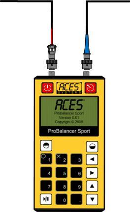
20 Equipment Required A device to collect vibration and phase data. A phase angle /speed sensing device A vibration sensing device Balance weights and hand tools.
 FAA-approved Guide to Propeller Balancing")
21 Equipment Required Approved references Airframe manual Propeller Manual Engine manual (in some cases) FAA-approved Guide to Propeller Balancing

22 Equipment Required Make sure the approval letter is attached to the Guide and references the material being used (document number, date, revision, and change numbers if applicable.)
23 Equipment Required AC20-37E Chapter 3 Paragraph 300.C.2.(d) When approved aircraft or propeller manufacturer s procedures are not available, there are other acceptable dynamic propeller balancing procedures. These include, but are not limited to ACES Publication No. 100-OM-01, entitled ACES Systems Guide to Propeller Balancing. Dynamic balancing of propellers using FAA-approved or - accepted dynamic propeller balancing procedures is not considered a major propeller repair unless the propeller static balance weights are altered or when using ACES type documents on propeller installations of 500 horsepower or more. (emphasis added)
24 BEFORE Setting Up the Equipment Propeller Inspection Prior to Balancing Ensure all Airworthiness Directives have been accomplished for the propeller you are going to balance. Determine if there is a balancing procedure published by the airframe, engine or propeller manufacturer; if there is, it will take precedence.
25 BEFORE Setting Up the Equipment Inspect the propeller blades for damage, nicks etc. refer to FAA Advisory Circular 20-37E which outlines care of metal propellers, and to applicable propeller manufacturers maintenance requirements. If balancing composite propeller blades, refer to the propeller manufacturer's procedures for repair of the propeller. Inspect propeller assembly for proper installation and security.
26 BEFORE Setting Up the Equipment Perform a visual inspection of the spinner and spinner bulkhead for cracks, stop drills and welding. Mass trim weights MUST NOT be attached to a part with any of these conditions. To prevent an excessive number of weights from being attached to the spinner, remove any mass trim weights attached from previous dynamic balance jobs. Static balance weight attached to the propeller hub by a certified propeller shop MUST NOT be removed.
27 BEFORE Setting Up the Equipment Inspect your sensor and its attached cable for obvious damage, such as, chips, pinches, or cuts in the plastic on the cable, and dints or scratches on the sensor, etcetera. Inspect your tachometer and its attached cable for obvious damage, such as, chips, pinches, or cuts in the plastic on the cable, scratches on the tachometer lens, etcetera. Ensure the batteries in your analyzer have a sufficient charge to complete the balance job.
28 Setting Up the Equipment Always attach the vibration sensor as near as possible to the forward most point of the engine and as close to inline with the engine bearing as possible. The base of the sensor should always point to the center of the prop shaft. The vibration sensor should not be in line with a cylinder and should be positioned at 12:00 whenever possible.
29 Setting Up the Equipment Attach the Phototach between 12 and 18 inches from the surface of the target blade and not perpendicular (90 degrees) to the surface of the blade. A 5 degree offset is best. The reflective tape should be a 2 inch long piece of 3M brand 7610, and not less than 1 inch wide. It should be installed no more than 14 inches out the prop blade from the center of the prop shaft.
30 Setting Up the Equipment Cables should be routed away from rotating and high temp components. Secure with wire ties or tape to prevent excessive movement and possible damage. Do not close windows or doors on the cables as this may pinch or cut them. Make sure connections at the analyzer are secure.

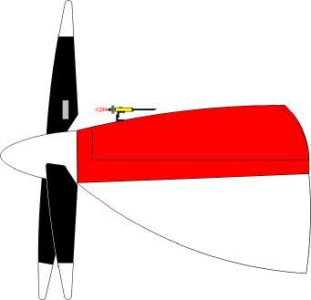
31 Setting Up the Equipment

32 Data Collection & Processing The vibration sensor is installed on the engine as near the front bearing as possible. The Phototach is mounted on the cowling, behind the propeller. The reflective tape is applied to the back side of the target propeller blade in line with the Phototach beam. The mass is the theoretical heavy spot in the propeller, and is located by correlating the bump from the vibration sensor and the amount of time that has passed since the Phototach signaled the passing of the reflective tape.


33 Data Collection & Processing The Reflective tape triggers a response as it passes the Phototach, which then sends an electrical signal to the analyzer. As the heavy spot on the propeller passes the vibration sensor, the sensor generates an electrical pulse and sends it to the analyzer.
34 Data Collection & Processing In this illustration, the vibration sensor and Phototach beam are co-located at the 12:00 or 0 degree position. Rotation is clock-wise from the viewers position. This is our starting point, elapsed time = 0
35 Data Collection & Processing The speed is 1 RPM. Fifteen seconds (90 degrees) of travel has occurred. In this sequence, the reflective tape has just entered the Phototach beam to trigger the tach event. Elapsed time = 15 seconds.
36 Data Collection & Processing In this sequence, the mass (heavy spot) is passing the accelerometer position, 15 seconds (90 degrees) after the tape passed the Phototach beam. Elapsed time = 30 seconds (180 degrees of travel).
37 Data Collection & Processing The tape and mass have both passed the 0 degree location. The unit now waits for the exact sequence to repeat for averaging. Elapsed time = 45 seconds (270 degrees of travel)
38 Data Collection & Processing
39 Data Collection & Processing The process is repeated while the analyzer averages out errors caused by momentary vibration events outside the running average.
40 Data Collection & Processing When sufficient data has been collected, the process is stopped by the analyzer and the averaged data displayed on screen. Notice that you have the option to Retake the data if desired.
41 Data Collection & Processing The analyzer will prompt you to shut down the engine. When less than 50 RPM are recognized by the analyzer, it will progress to the solution screen.
42 Data Collection & Processing A solution is then provided by the analyzer based on a temporarily stored influence coefficient or a calculated test weight. If required, the process is then repeated for refinement of the solution. Notice you have the option to split the weights between two angles if needed.
43 The Balancing Process With the equipment installed and all previously installed trim weights removed, head the airplane into the wind (10 KTS maximum) and begin the data collection.
44 The Balancing Process The analyzer will show a screen instructing you to warm the engine and advance your RPM to the designated balancing RPM.
45 The Balancing Process The analyzer will collect and average data until a sufficient amount of data samples have been collected. This should take between ten and thirty seconds under ideal conditions.
46 The Balancing Process When the sufficient data has need collected, the Review screen shows the averaged amplitude and the phase angle of the out of balance condition.
47 The Balancing Process The analyzer will prompt you to shut down. When a RPM reading of less than 50 RPM is indicated the analyzer will progress.
48 The Balancing Process After the analyzer detects the engines are shut down, it will suggest a balance solution. If you require a two hole solution select 1 for yes.
49 The Balancing Process If you split the weights, the analyzer will ask you for the angles of the two available holes. Enter the angles and press go.
50 The Balancing Process The analyzer screen will display its suggestion and ask you for the actual angle and weights you installed. This screen will repeat for each hole location, if you chose to split the weight.
51 The Balancing Process The start engine screen will be displayed again. The analyzer will repeat this balance process until the vibration has been driven below.07 IPS.
52 The Balancing Process Where to place the weights Test weights can be placed under the spinner retention screws. It may be necessary to use longer screws for the test weights. If doing so, account for the delta between the normal and the longer screw. Be sure you are measuring the angles in relation to the reflective tape.
53 The Balancing Process Permanent weights may be installed under the flange or on the bulkhead. If installed under the flange, offset from spinner attaching screws by four times the diameter of the spinner screws.
54 The Balancing Process DO NOT use the spinner attachment screws for permanent weight applications. Apply an equal number of washers to each side of the bulkhead and compensate for the shortened arm when moving weight(s) to the spinner bulkhead.
55 Correction Calculation Diameter of spinner divided by 2 = radius of spinner (ex: 14 / 2 = 7.0 ) Minus distance from test weight to permanent weight = permanent weight radius (ex: = 5.5 ) Required weight to balance x radius of spinner = net effect (ex: 25 g x 7.0 = 175 Gram inches) Divide by permanent weight radius = permanent weight (ex: 175 / 5.5 = 31.8 grams)
56 Avoiding the Pitfalls If you remove the spinner in order to remove previously installed trim weights, index it and make sure it is always reinstalled by the index mark. Check inside the spinner for foreign objects, excess grease and trapped water.
57 Avoiding the Pitfalls Unstable or erratic RPM readings on the analyzer are most commonly caused by: Angle of the Phototach relative to the tape. Phototach outside the 18 inch maximum or inside the 12 inch minimum distance. Tape too narrow for the velocity of the prop. Dirty or misaligned tape. Defective Phototach or Cable.
58 Avoiding the Pitfalls Unstable or erratic vibration amplitude readings on the analyzer are most commonly caused by: Damaged or inoperative sensor Pinched, Cut, or shorted cable Unstable tachometer input. Mechanical defects of the assembly being balanced.

59 Avoiding the Pitfalls You may also adjust the Phototach gain. Remove the screw holding the clear plastic cover on the aft end of the unit.

60 Avoiding the Pitfalls The gain adjustment is the brass screw at the right. Make adjustment in a controlled environment such as with a bench grinder in a shop.
61 Avoiding the Pitfalls Adjust the speed of the prop as closely as possible to the exact target RPM on EVERY run. A change in RPM will change the influence of an attached weight. Subsequent solutions will not have the same calculated results at different speeds.
62 Avoiding the Pitfalls If an established influence for the engine and prop combination being balanced is not being used, the first weight the analyzer will ask you to install is a TEST weight. This weight may cause the vibration amplitude to increase. The intention of the test weight is only to induce a measurable change, not necessarily reduce the vibration.
63 Avoiding the Pitfalls If the suggested TEST weight is greater than your experience tells you is necessary to induce a change, reduce the weight and enter the exact amount and angle of attachment into the analyzer. Remember that the amplitude may actually go up. This is not a malfunction of the equipment. Continue the balance process.
64 Avoiding the Pitfalls Test weight calculation. Test Weight in Grams = ((Engine Horsepower/10)+30)*IPS g = (1000/10)+30)*1.0 g = (100+30)*1 g = 130
65 Avoiding the Pitfalls There is no difference in the propeller balance procedure for a radial engine, opposed engine, turboprop, geared, variable pitch, or fixed pitch propeller.
66 Avoiding the Pitfalls A variety of mechanical problems can show up at propeller turning speed these include Propeller out of track. Crankshaft unbalance. Bearing problems. Loose or worn components in the engine. Defective crankshaft counterweights. Loose or worn components in the propeller hub. Loose airframe components.
67 Avoiding the Pitfalls Some indications are: Applying numerous (more than 3 or 4) solutions without reducing the amplitude. Phase angle changing radically between runs. Phase angle that changes dramatically during data acquisition. (At amplitudes below approximately.05 IPS this is not a defect.)
68 Avoiding the Pitfalls In any of these cases, you will have little to no success with your balancing efforts. If you feel you are chasing the solution, check the equipment on another application before blaming your difficulties on the analyzer.
DynaVibe Procedure for Aircraft Propellers
 Application Note: RPX-AFA-PR-BAL-00-A September 2016 This application note is for reference only and does not modify, replace, substitute for, or supersede official regulations or the aircraft manufacturer
WHIRLWIND. Owner s Manual Series (Rev ) Serial Number: Manufacture Date: A V I A T I O N Model: WHIRL WIND AVIATION
 Serial Number: Manufacture Date: A V I A T I O N Model: WHIRL WIND AVIATION") WHIRLWIND A V I A T I O N Model: 100-4 Serial Number: 100-4- Manufacture Date: M a nufacturer of Composite Constant Speed P r o pellers Owner s Manual 100-4 Series (Rev 2014-2) WHIRL WIND AVIATION 1419
WHIRLWIND A V I A T I O N Model: 100-4 Serial Number: 100-4- Manufacture Date: M a nufacturer of Composite Constant Speed P r o pellers Owner s Manual 100-4 Series (Rev 2014-2) WHIRL WIND AVIATION 1419
WHIRLWIND. Owner s Manual 151H Series (Rev ) Model: 151H Serial Number: Manufacture Date: A V I A T I O N WHIRL WIND AVIATION
 Model: 151H Serial Number: Manufacture Date: A V I A T I O N WHIRL WIND AVIATION") WHIRLWIND A V I A T I O N M a nufacturer of Composite Constant Speed P r o pellers Model: 151H Serial Number: Manufacture Date: Owner s Manual 151H Series (Rev 2014-2) WHIRL WIND AVIATION 1419 STATE ROUTE
WHIRLWIND A V I A T I O N M a nufacturer of Composite Constant Speed P r o pellers Model: 151H Serial Number: Manufacture Date: Owner s Manual 151H Series (Rev 2014-2) WHIRL WIND AVIATION 1419 STATE ROUTE
WHIRLWIND. Owner s Manual 400C-M14 Series (Rev ) Model: 400C-M14 Serial Number: Manufacture Date: A V I A T I O N WHIRL WIND AVIATION
 Model: 400C-M14 Serial Number: Manufacture Date: A V I A T I O N WHIRL WIND AVIATION") WHIRLWIND A V I A T I O N M a nufacturer of Composite Constant Speed P r o pellers Model: 400C-M14 Serial Number: Manufacture Date: Owner s Manual 400C-M14 Series (Rev 2014-2) WHIRL WIND AVIATION 1419
WHIRLWIND A V I A T I O N M a nufacturer of Composite Constant Speed P r o pellers Model: 400C-M14 Serial Number: Manufacture Date: Owner s Manual 400C-M14 Series (Rev 2014-2) WHIRL WIND AVIATION 1419
SERVICE LETTER. Model 1A162 Propeller, and the McCauley Fixed Pitch Propeller Service Manual.
 September 4, 2009 TITLE MODEL 1A162/TCD6754 PROPELLER SERVICE INFORMATION UPDATE TO: FAA-Approved Propeller Repair Stations, Aircraft Manufacturers, Owners and Operators EFFECTIVITY Model 1A162 Propeller,
WHIRLWIND. Owner s Manual 400 Rocket Series (Rev ) Model: 400 Rocket Serial Number: Manufacture Date: A V I A T I O N WHIRL WIND AVIATION
 Model: 400 Rocket Serial Number: Manufacture Date: A V I A T I O N WHIRL WIND AVIATION") WHIRLWIND A V I A T I O N M a nufacturer of Composite Constant Speed P r o pellers Model: 400 Rocket Serial Number: Manufacture Date: Owner s Manual 400 Rocket Series (Rev 2014-2) WHIRL WIND AVIATION 1419
WHIRLWIND A V I A T I O N M a nufacturer of Composite Constant Speed P r o pellers Model: 400 Rocket Serial Number: Manufacture Date: Owner s Manual 400 Rocket Series (Rev 2014-2) WHIRL WIND AVIATION 1419
WHIRLWIND. Owner s Manual 375RV Series (Rev ) Model: 375RV Serial Number: 375RV- Manufacture Date: A V I A T I O N WHIRL WIND AVIATION
 Model: 375RV Serial Number: 375RV- Manufacture Date: A V I A T I O N WHIRL WIND AVIATION") WHIRLWIND A V I A T I O N M a nufacturer of Composite Constant Speed P r o pellers Model: 375RV Serial Number: 375RV- Manufacture Date: Owner s Manual 375RV Series (Rev 2014-3) WHIRL WIND AVIATION 1419
WHIRLWIND A V I A T I O N M a nufacturer of Composite Constant Speed P r o pellers Model: 375RV Serial Number: 375RV- Manufacture Date: Owner s Manual 375RV Series (Rev 2014-3) WHIRL WIND AVIATION 1419
Accident Prevention Program
 Accident Prevention Program Maintenance Aspects of Owning Your Own Airplane Introduction As an owner-pilot, FAR Part 43 allows you to perform certain types of inspections and maintenance on your airplane.
WHIRLWIND. Owner s Manual 200C / 400C Series (Rev ) Model: Serial Number: Manufacture Date: A V I A T I O N WHIRL WIND AVIATION
 Model: Serial Number: Manufacture Date: A V I A T I O N WHIRL WIND AVIATION") WHIRLWIND A V I A T I O N M a nufacturer of Composite Constant Speed P r o pellers Model: Serial Number: Manufacture Date: Owner s Manual 200C / 400C Series (Rev 2014-2) WHIRL WIND AVIATION 1419 STATE
WHIRLWIND A V I A T I O N M a nufacturer of Composite Constant Speed P r o pellers Model: Serial Number: Manufacture Date: Owner s Manual 200C / 400C Series (Rev 2014-2) WHIRL WIND AVIATION 1419 STATE
HARTZELL PROPELLER INC.
 HARTZELL PROPELLER INC. One Propeller Place Piqua, Ohio 45356-2634 U.S.A. Telephone: 937.778.4200 Fax: 937.778.4391 MANUAL REVISION TRANSMITTAL Manual (61-00-11) Propeller Owner's Manual and Logbook REVISION
Propeller Assembly. 1. General
 Propeller Assembly GENERAL 61-10: PROPELLER ASSEMBLY 1. General The propeller assembly consists of a hollow aluminum hub which supports the propeller blades and also houses the pitch changing mechanism.
ROBINSON MODEL R-44 HELICOPTER TRACK AND BALANCE
 Application Note AN-MV2-R44 Rev 02-10 May 2012 MicroVib II Aircraft Analyzer Helicopter Track and Balance ROBINSON MODEL R-44 HELICOPTER TRACK AND BALANCE Dynamic Solutions Systems, Inc. (760) 598-4000
IMPACT REGISTER, INC. PRECISION BUILT RECORDERS SINCE 1914
 IMPACT REGISTER, INC. PRECISION BUILT RECORDERS SINCE 1914 RM-3WE (THREE WAY) ACCELEROMETER GENERAL The RM-3WE accelerometer measures and permanently records, for periods of 30, 60, and 90 days, the magnitude,
TYPE CERTIFICATE DATA SHEET
 TYPE CERTIFICATE DATA SHEET No. IM.P.137 for Propeller 3C1 ( ) series propellers Type Certificate Holder One Propeller Place Piqua, OH 45356 2634 USA For Model: 3C1 R919A1 3C1 L675A1 TE.CERT.00050 001
AVIAT AIRCRAFT INC. P.O. Box South Washington Afton, WY USA Fax:
 DATE: 18 December 2000 REVISION: Orig. AIRCRAFT: PITTS SPECIAL P.O. Box 1240 672 South Washington Afton, WY 83110 USA 307-886-3151 Fax: 307-885-9674 aviat@aviataircraft.com SUBJECT: Propeller Accumulator
HARTZELL PROPELLER INC.
 HARTZELL PROPELLER INC. One Propeller Place Piqua, Ohio 45356-2634 U.S.A. Telephone: 937.778.4200 Fax: 937.778.4391 MANUAL REVISION TRANSMITTAL Manual (61-00-39) Propeller Owner's Manual and Logbook REVISION
Mtn View Aviation An AP Enterprises, LLC Company PO Box 31 Hubbard, OR MVA-206C10M&O. Installation Instructions
 Mtn View Aviation An AP Enterprises, LLC Company PO Box 31 Hubbard, OR 97032 Installation and Instructions for Continued Airworthiness for Door Steward Cessna 206/207 - Utility Door In Accordance with
WHIRLWIND. Owner s Manual 200G-CS & 210 (Rev ) Model: Serial Number: Manufacture Date: A V I A T I O N WHIRL WIND AVIATION
 Model: Serial Number: Manufacture Date: A V I A T I O N WHIRL WIND AVIATION") WHIRLWIND A V I A T I O N M a nufacturer of Composite Constant Speed P r o pellers Model: Serial Number: Manufacture Date: Owner s Manual 200G-CS & 210 (Rev 2014-2) WHIRL WIND AVIATION 1419 STATE ROUTE
WHIRLWIND A V I A T I O N M a nufacturer of Composite Constant Speed P r o pellers Model: Serial Number: Manufacture Date: Owner s Manual 200G-CS & 210 (Rev 2014-2) WHIRL WIND AVIATION 1419 STATE ROUTE
Sequoia power steering rack service Match-mounting wheels and tires Oxygen sensor circuit diagnosis
 In this issue: Sequoia power steering rack service Match-mounting wheels and tires Oxygen sensor circuit diagnosis PHASE MATCHING Often referred to as match mounting, phase matching involves mounting the
AIRCRAFT ENGINE MECHANIC, 8602
 May 2000 Federal Wage System Job Grading Standards FEDERAL WAGE SYSTEM JOB GRADING STANDARD FOR AIRCRAFT ENGINE MECHANIC, 8602 Theodore Roosevelt Building 1900 E Street, NW Washington, DC 20415-8330 Classification
pages 4-1 thru 4-4 pages 4-1 thru 4-4
 HARTZELL PROPELLER INC. One Propeller Place Piqua, Ohio 45356-2634 U.S.A. Telephone: 937.778.4200 Fax: 937.778.4391 MANUAL REVISION TRANSMITTAL Manual (61-00-15) Propeller Owner's Manual and Logbook REVISION
C I R R U S PROPELLER GENERAL
 PROPELLER 1. GENERAL The airplane employs a 3 blade, constant speed, non-feathering propeller. The blades (composite or aluminum) are mounted in an aluminum hub which contains the pitch changing mechanism
TABLE of CONTENTS PFS-15102
 Section TABLE of CONTENTS PFS-15102 Installation Instructions and Page 1.0 INTRODUCTION...3 2.0 KIT CONTENTS...4 3.0 PREPARATION...5 4.0 INSTALLATION OF PFS EXHAUST SYSTEM...5 4.1 - Installing Collector
BLADEcontrol Greater output less risk
 BLADEcontrol Greater output less risk 2 Expensive surprises? Unnecessary downtime? Rotor blade monitoring increases the output of your wind turbine generator system 3 Detect damage at an early stage For
Airworthiness Directive Schedule
 Airworthiness Directive Schedule Aeroplanes Cessna 120 26 November 2015 Notes 1. This AD schedule is applicable to Cessna 120 aircraft manufactured under Federal Aviation Administration (FAA) Type Certificate
PROPELLER INSTALLATION & OPERATION MANUAL MODEL: GA200CN-3B
 PROPELLER INSTALLATION & OPERATION MANUAL MODEL: GA200CN-3B WHIRLWIND PROPELLERS CORPORATION 1800-C Joe Crosson Drive El Cajon, CA 92020 USA www.whirlwindpropellers.com NOVEMBER 2013 1 of 11 GA200CN-3B
WHIRLWIND. Owner s Manual 200RV Series (Rev ) Model: 200RV Serial Number: 200RV- Manufacture Date: A V I A T I O N WHIRL WIND AVIATION
 Model: 200RV Serial Number: 200RV- Manufacture Date: A V I A T I O N WHIRL WIND AVIATION") WHIRLWIND A V I A T I O N M a nufacturer of Composite Constant Speed P r o pellers Model: 200RV Serial Number: 200RV- Manufacture Date: Owner s Manual 200RV Series (Rev 2014-2) WHIRL WIND AVIATION 1419
WHIRLWIND A V I A T I O N M a nufacturer of Composite Constant Speed P r o pellers Model: 200RV Serial Number: 200RV- Manufacture Date: Owner s Manual 200RV Series (Rev 2014-2) WHIRL WIND AVIATION 1419
CIRRUS AIRPLANE MAINTENANCE MANUAL
 UNSCHEDULED MAINTENANCE CHECKS 1. DESCRIPTION The following describes those maintenance checks and inspections on the aircraft which are dictated by special or unusual conditions which are not related
DYNAMIC BALANCING VIBRATION ANALYSIS
 & DYNAMIC BALANCING VIBRATION ANALYSIS P R O D U C T C ATA L O G Testing, Tools and Ground Support Equipment WE SUPPLY, TO KEEP THEM Flying In the aviation industry, precision and support are of vital
CIRRUS AIRPLANE MAINTENANCE MANUAL
 PROPELLER 1. GENERAL The airplane employs a 3 blade, constant speed, non-feathering propeller. The blades (composite or aluminum) are mounted in an aluminum hub which contains the pitch changing mechanism
PROPELLERS - PROPELLER SLIP RING MOUNTING PLATE INSPECTION AND REPAIR
 Beechcraft TITLE: PROPELLERS - PROPELLER SLIP RING MOUNTING PLATE INSPECTION AND REPAIR 1. Planning Information A. Effectivity (1) Airplanes Airplanes that have accomplished installation of Hartzell STC
Unscheduled Maintenance Checks
 CIRRUS AIRPLANE MAINTENANCE MANUAL CHAPTER 5-50: UNSCHEDULED MAINTENANCE CHECKS GENERAL Unscheduled Maintenance Checks 5-50: UNSCHEDULED MAINTENANCE CHECKS 1. General The following describes those maintenance
550 T.I. ENGINE FOR THE CESSNA 206 STC FOR TELEDYNE CONTINENTAL IO-550-N FOR THE U 206 & TU 206 (SERIAL NUMBERS 2200 THROUGH 7020)
") 550 T.I. ENGINE FOR THE CESSNA 206 STC FOR TELEDYNE CONTINENTAL IO-550-N FOR THE U 206 & TU 206 (SERIAL NUMBERS 2200 THROUGH 7020) You Can Have More Than A New Engine In Your Cessna* You Can Experience
550 T.I. ENGINE FOR THE CESSNA 206 STC FOR TELEDYNE CONTINENTAL IO-550-N FOR THE U 206 & TU 206 (SERIAL NUMBERS 2200 THROUGH 7020) You Can Have More Than A New Engine In Your Cessna* You Can Experience
TYPE CERTIFICATE DATA SHEET
 TCDS No.: IM.P.124 TYPE CERTIFICATE DATA SHEET No. IM.P.124 for 3A1 series propeller Type Certificate Holder One Propeller Place Piqua, OH 45356 2634 USA For Models: 3A1 TP TE.CERT.00050 001 European Aviation
For Experimental Aircraft Only: Glastar, Sportsman 2+2, and Similar with Lycoming O320 or O360 Parallel Valve Engines
 REPORT NAME: KIT PFS-16104 INSTALLATION INSTRUCTIONS AND INSTRUCTIONS FOR CONTINUED AIRWORTHINESS APPROVAL PFS ENG DATE: REPORT NUMBER: PFS-16250-EXP REVISION: A REPORT DATE: 02/14/06 PREPARED BY: Tom
INDEX. Preflight Inspection Pages 2-4. Start Up.. Page 5. Take Off. Page 6. Approach to Landing. Pages 7-8. Emergency Procedures..
 INDEX Preflight Inspection Pages 2-4 Start Up.. Page 5 Take Off. Page 6 Approach to Landing. Pages 7-8 Emergency Procedures.. Page 9 Engine Failure Pages 10-13 Propeller Governor Failure Page 14 Fire.
DEPARTMENT OF TRANSPORTATION FEDERAL AVIATION ADMINISTRATION AIRCRAFT SPECIFICATION NO. A-804. Continental E165-2 (see Item 106 for optional engines)
") DEPARTMENT OF TRANSPORTATION FEDERAL AVIATION ADMINISTRATION A-804 Revision 14 LAND-AIR (TEMCO) (LUSCOMBE) 11A 11E April 6, 2005 AIRCRAFT SPECIFICATION NO. A-804 Type Certificate Holder Luscombe Aircraft
DEPARTMENT OF TRANSPORTATION FEDERAL AVIATION ADMINISTRATION A-804 Revision 14 LAND-AIR (TEMCO) (LUSCOMBE) 11A 11E April 6, 2005 AIRCRAFT SPECIFICATION NO. A-804 Type Certificate Holder Luscombe Aircraft
WHIRL WIND PROPELLERS Ground Adjustable (GA) Aircraft Propeller Installation & Maintenance Instructions. Propeller Model: GA-UL350.
 Aircraft Propeller Installation & Maintenance Instructions. Propeller Model: GA-UL350.") WHIRL WIND PROPELLERS Ground Adjustable (GA) Aircraft Propeller Installation & Maintenance Instructions Propeller Model: GA-UL350 Engine: UL350 WHIRLWIND PROPELLERS CORPORATION 1800-C Joe Crosson Drive
WHIRL WIND PROPELLERS Ground Adjustable (GA) Aircraft Propeller Installation & Maintenance Instructions Propeller Model: GA-UL350 Engine: UL350 WHIRLWIND PROPELLERS CORPORATION 1800-C Joe Crosson Drive
ABI WHEEL & BRAKE KIT
 INSTALLATION INSTRUCTIONS and INSTRUCTIONS FOR CONTINUED AIRWORTHINESS for the installation of ABI-199-62 WHEEL & BRAKE KIT for CESSNA AIRCRAFT SERIES 180, 185, 206 Doc No.: ABI-199-62-4 REV B 04/21/2017
500W Series Instructions for Continued Airworthiness
 Instructions for Continued Airworthiness Document Number Garmin International, Inc. 1200 E. 151st Street Olathe, Kansas 66062 USA Record of Revision Rev. Date Description of Change 1 10-19-06 Initial Release
550 T.I. ENGINE FOR THE CESSNA 210 STC FOR TELEDYNE CONTINENTAL IO-550-P FOR THE 210 & T210 (SERIAL NUMBERS THROUGH K, L, M & N)
") 550 T.I. ENGINE FOR THE CESSNA 210 STC FOR TELEDYNE CONTINENTAL IO-550-P FOR THE 210 & T210 (SERIAL NUMBERS 21059200 THROUGH 21064897 K, L, M & N) You Can Have More Than A New Engine In Your Cessna* You
550 T.I. ENGINE FOR THE CESSNA 210 STC FOR TELEDYNE CONTINENTAL IO-550-P FOR THE 210 & T210 (SERIAL NUMBERS 21059200 THROUGH 21064897 K, L, M & N) You Can Have More Than A New Engine In Your Cessna* You
HARTZELL PROPELLER INC. SERVICE BULLETIN TRANSMITTAL SHEET HC-SB Propeller - Blade, Blade Retention Bearing, and Hub Inspection.
 TRANSMITTAL SHEET May 20, 2013 This page transmits Revision 2 to Service Bulletin. Original Issue, dated September 15/04 Revision 1, dated January 14/05 Revision 2, dated May 20/13 Propeller assemblies
Accident Prevention Program
 Accident Prevention Program Part I ENGINE OPERATION FOR PILOTS by Teledyne Continental Motors SAFE ENGINE OPERATION INCLUDES: Proper Pre-Flight Use the correct amount and grade of aviation gasoline. Never
SERVICE LETTER HM-SL-001 Overhaul Periods and Life Limits for Hartzell Propeller Inc. Maritime (Non-Aviation) Propellers
 Propellers") 1. Planning Information A. Effectivity (1) All Hartzell Propeller Inc. and Governors, regardless of installation, are affected by this Service Letter. CAUTION: B. Concurrent Requirements DO NOT USE OBSOLETE
1. Planning Information A. Effectivity (1) All Hartzell Propeller Inc. and Governors, regardless of installation, are affected by this Service Letter. CAUTION: B. Concurrent Requirements DO NOT USE OBSOLETE
CHAPTER 22 SERVICING
 CHAPTER 22 SERVICING Section Title 22-10 Main Rotor Gearbox......................................... 22.1 22-11 Cleaning Chip Detector..................................... 22.3 22-12 Cleaning Sight Gage.......................................
INSTRUCTIONS FOR CONTINUED AIRWORTHINESS
 Van Horn Aviation, L.L.C. 1510 W. Drake Drive Tempe, Arizona 85283 INSTRUCTIONS FOR CONTINUED AIRWORTHINESS ICA MANUAL Tail Rotor Blade Assembly 2062200-101/-301 Eligible for Installation on Model 206L4
Ratcheting Pullers Reversible Puller Combination Pullers Slide Hammer Pullers Heavy Duty C-Clamps...
 C L A M P I N G & P U L L I N G Ratcheting Pullers... 1137 Reversible Puller... 1139 Combination Pullers... 1139 Slide Hammer Pullers... 1139 Heavy Duty C-Clamps... 1141 General Service C-Clamps... 1142
Service Bulletin. SB-GA Issue 1. Subject: Horizontal Stabiliser Attachment Area Inspection and Reinforcement. Applicability: Amendments:
 PO Box 881, Morwell, Victoria 3840, Australia Ph + 61 (0) 3 5172 1200 Fax + 61 (0) 3 5172 1201 www.mahindraaerospace.com Service Bulletin SB-GA8-2016-163 Issue 1 OPTIONAL Subject: Horizontal Stabiliser
Chapter 3: Aircraft Construction
 Chapter 3: Aircraft Construction p. 1-3 1. Aircraft Design, Certification, and Airworthiness 1.1. Replace the letters A, B, C, and D by the appropriate name of aircraft component A: B: C: D: E: 1.2. What
INSTALLATION MANUAL AND OPERATING INSTRUCTIONS Electric Attitude Indicator
 INSTALLATION MANUAL AND OPERATING INSTRUCTIONS 4200-21 Electric Attitude Indicator Mid-Continent Instruments and Avionics Manual Number 9016182-1 9400 E 34 th Street N, Wichita, KS 67226 USA Revision D,
D'Shannon Products, Ltd County Road 134 Buffalo, MN Supplemental Type Certificate SA2200SW. Installation Instructions
 1992 D'Shannon Products, Ltd. Supplemental Type Certificate SA2200SW Installation Instructions Teledyne Continental IO-520-B, -BA, -BB and IO-550-B Engines Series II Beechcraft 35 and 33 Airplanes Eligible
SFI SPECIFICATION 15.2 EFFECTIVE: MAY 1, 2008 *
 SFI SPECIFICATION 15.2 EFFECTIVE: MAY 1, 2008 * PRODUCT: Drag Race Front Wheels 1.0 GENERAL INFORMATION 1.1 This SFI Specification establishes uniform test procedures and minimum standards for evaluating
SHAFT ALIGNMENT FORWARD
 Service Application Manual SAM Chapter 630-76 Section 24 SHAFT ALIGNMENT FORWARD One of the basic problems of any installation is aligning couplings or shafts. Therefore, this section will endeavor to
LANCAIR LEGACY PRE-TEST FLIGHT INSPECTION (8-04)
") LANCAIR LEGACY PRE-TEST FLIGHT INSPECTION (8-04) OWNER PHONE # ADDRESS N SERIAL # AIRCRAFT TYPE DATE / / TACH TIME hrs. TOTAL TIME hrs. EMPTY WEIGHT CG. PAINT & INTERIOR? YES NO ENGINE TYPE PROPELLER ALL
LANCAIR LEGACY PRE-TEST FLIGHT INSPECTION (8-04) OWNER PHONE # ADDRESS N SERIAL # AIRCRAFT TYPE DATE / / TACH TIME hrs. TOTAL TIME hrs. EMPTY WEIGHT CG. PAINT & INTERIOR? YES NO ENGINE TYPE PROPELLER ALL
OPTIONAL SERVICE BULLETIN OSB
 DAI OSB 42-131 Page 1 of 4 OPTIONAL SERVICE BULLETIN OSB 42-131 I TECHNICAL DETAILS I.1 Category Optional. I.2 Airplanes affected Type: DA 42, DA 42 M Serial numbers: 42.004 through 42.427 42.AC001 through
INSTRUCTIONS FOR CONTINUED AIRWORTHINESS
 INSTRUCTIONS FOR CONTINUED AIRWORTHINESS Beechcraft Super King Air 200/A200/B200 Series Airplanes Equipped With Pratt & Whitney PT6A-52 Engines Installed Per STC SA10824SC Revision A Document Number 200708-30
Airworthiness Directive Schedule
 Airworthiness Directive Schedule Aeroplanes 27 October 2011 Notes 1. This AD schedule is applicable to aircraft manufactured under Federal Aviation Administration (FAA) Type Certificate No. A18SO. 2. The
500W Series Instructions for Continued Airworthiness
 Instructions for Continued Airworthiness Document Number 190-00357-65 Rev. B Garmin Ltd. Or its subsidiaries c/o Garmin International, Inc. 1200 E. 151st Street Olathe, Kansas 66062 USA Record of Revision
SAMPLE BLUE STAR CONVERSION INSTALLATION OF CONTINENTAL IO-470-N BEECH MODEL J35, K35, M35 LWS C-470-N. REVISION 2. September 16, 1992 STC SA5635SW
 BLUE STAR CONVERSION INSTALLATION OF CONTINENTAL IO-470-N BEECH MODEL J35, K35, M35. REVISION 2 September 16, 1992 STC SA5635SW SAMPLE 1 1992SAMPLE BLUE STAR CONVERSION Table of Contents Page Description
HARTZELL PROPELLER INC.
 HARTZELL PROPELLER INC. One Propeller Place Piqua, Ohio 45356-2634 U.S.A. Telephone: 937.778.4200 Fax: 937.778.4391 MANUAL REVISION TRANSMITTAL Manual (61-00-49) Propeller Owner's Manual and Logbook REVISION
 Page 1 of 29 Section 04-05: Suspension, Computer Controlled 1997 Town Car Workshop Manual DIAGNOSIS AND TESTING Procedure revision date: 05/16/2000 Suspension, Computer Controlled Inspection and Verification
HARTZELL PROPELLER INC. SERVICE BULLETIN TRANSMITTAL SHEET SERVICE BULLETIN HC-SB Propeller - Propeller Installation.
 TRANSMITTAL SHEET March 16, 2006 This page transmits Revision 1 to Service Bulletin. Original, dated Revision 1, dated Mar 16/06 FAA approval has been obtained on technical data in this publication that
SERVICE INFORMATION LETTER # 0121 Addition A. Subject; Tracking the Enstrom Rotor System using the Chadwick 2000 balance system.
 SERVICE INFORMATION LETTER # 0121 Addition A Date: Subject; Tracking the Enstrom Rotor System using the Chadwick 2000 balance system. Models: All models Effectively: All Serial Numbers Experience shows
TEMPORARY REVISION NUMBER
 TEMPORARY REVISION NUMBER 7 DATED 1 DECEMBER 2011 MANUAL TITLE MANUAL NUMBER - PAPER COPY TEMPORARY REVISION NUMBER Model 188 & T188 Series 1966 Thru 1984 Service Manual D2054-1-13 D2054-1TR7 MANUAL DATE
Heat Engines Lab 12 SAFETY
 HB 1-05-09 Heat Engines 1 Lab 12 1 i Heat Engines Lab 12 Equipment SWS, 600 ml pyrex beaker with handle for ice water, 350 ml pyrex beaker with handle for boiling water, 11x14x3 in tray, pressure sensor,
SERVICE BULLETIN SB
 SERVICE BULLETIN No. Compliance recommended Subject: Aircraft affected: EA 300/S (EXTRA 300S) up to SN 1036 1 EA 300/L (EXTRA 300L) up to S/N 1326 2 EA 300/200 (EXTRA 200) up to S/N 1046 1 EA 300/SC (EXTRA
Tribal Knowledge, converting an Enstrom Piston helicopter from Lamiflex bearings to TT straps
 Tribal Knowledge, converting an Enstrom Piston helicopter from Lamiflex bearings to TT straps The Airwolf kit comes with all parts necessary for assembly and is pre-packaged in shock proof packaging. 1
HARTZELL PROPELLER INC.
 HARTZELL PROPELLER INC. One Propeller Place Piqua, Ohio 45356-2634 U.S.A. Telephone: 937.778.4200 Fax: 937.778.4215 MANUAL REVISION TRANSMITTAL Manual (61-00-49) Propeller Owner's Manual and Logbook REVISION
Airworthiness Directive
 Airworthiness Directive AD No.: 2016-0120 Issued: 17 June 2016 EASA AD No.: 2016-0120 Note: This Airworthiness Directive (AD) is issued by EASA, acting in accordance with Regulation (EC) 216/2008 on behalf
INSTRUCTIONS FOR CONTINUED AIRWORTHINESS
 INSTRUCTIONS FOR CONTINUED AIRWORTHINESS INSTALLED IN AIRCRAFT LISTED IN APPROVED MODEL LIST, Issue Date RECORD OF REVISIONS Upon receipt of revisions, insert the revised pages into this document and enter
INSTRUCTIONS FOR CONTINUED AIRWORTHINESS
 INSTRUCTIONS FOR CONTINUED AIRWORTHINESS for GROVE MODEL 40-108 & 40-208 MAIN WHEELS DOCUMENT 12012-12 REV IR January 16, 2012 TABLE OF CONTENTS SECTION PAGE Title Page...1 Table of Contents...2 Record
SERVICE LETTER TITLE EXHAUST - TRANSMITTAL OF LYCOMING SERVICE BULLETIN NO 627C, EXHAUST SYSTEM INSPECTION SERIAL NUMBERS
 Single Engine MANDATORY SERVICE LETTER SEL-78-03 TITLE EXHAUST - TRANSMITTAL OF LYCOMING SERVICE BULLETIN NO 627C, EXHAUST SYSTEM INSPECTION EFFECTIVITY REASON MODEL T206H SERIAL NUMBERS T20608001 and
SFI SPECIFICATION 18.1 EFFECTIVE: JUNE 17, 1999 *
 SFI SPECIFICATION 18.1 EFFECTIVE: JUNE 17, 1999 * PRODUCT: Crankshaft Hub Harmonic Dampers 1.0 GENERAL INFORMATION 1.1 This SFI Specification establishes uniform test procedures and minimum standards for
SFI SPECIFICATION 15.4 EFFECTIVE: JULY 20, 2010 * PRODUCT: Top Fuel and Funny Car Drag Race Drive Beadlock Wheels
 SFI SPECIFICATION 15.4 EFFECTIVE: JULY 20, 2010 * PRODUCT: Top Fuel and Funny Car Drag Race Drive Beadlock Wheels 1.0 GENERAL INFORMATION 1.1 This SFI Specification establishes uniform test procedures
2.0 KIT CONTENTS INSTALLATION OF PFS EXHAUST SYSTEM INSTRUCTIONS FOR CONTINUED AIRWORTHINESS PASSENGER SIDE VIEW...
 TABLE of CONTENTS 1.0 INTRODUCTION... 3 1.1 GENERAL... 3 1.2 DESCRIPTION... 3 1.3 UPGRADES... 3 2.0 KIT CONTENTS... 4 2.1 CLASSIC TAILPIPE KITS... 4 2.2 SHORT STACK TAILPIPE KITS... 5 3.0 PREPARATION...
LG Alert TM Helping Drivers Operate Safely. LG Alert Lateral Acceleration Indicator User / Installation Manual
 INTRODUCTION US Pat. No. 6,130,608 The is intended for use as an early alert system to assist drivers in recognizing when they are exceeding set maximum maneuvering limits of the vehicle. The device monitors
Based on the findings, a preventive maintenance strategy can be prepared for the equipment in order to increase reliability and reduce costs.
 What is ABB MACHsense-R? ABB MACHsense-R is a service for monitoring the condition of motors and generators which is provided by ABB Local Service Centers. It is a remote monitoring service using sensors
CHAPTER 8 WEIGHT AND BALANCE. Section Title Page
 CHAPTER 8 WEIGHT AND BALANCE Section Title Page 8-10 Leveling.......................................... 8.1 8-11 Leveling for Weight and Balance................. 8.1 8-12 Leveling for Rigging..........................
Dynamic Behavior Analysis of Hydraulic Power Steering Systems
 Dynamic Behavior Analysis of Hydraulic Power Steering Systems Y. TOKUMOTO * *Research & Development Center, Control Devices Development Department Research regarding dynamic modeling of hydraulic power
PROPELLERS (ATA Chapter 61)
") INTRODUCTION PROPELLER GOVERNOR FEATHERING SYSTEM OPERATION LIMITATIONS DIAGRAM PROPELLERS (ATA Chapter 61)..61.1..61.1..61.1.61.2. 61.2 Feathering Oil Supply.. 61.2 Propeller Governor System.. 61.3 PROPELLERS
INTRODUCTION PROPELLER GOVERNOR FEATHERING SYSTEM OPERATION LIMITATIONS DIAGRAM PROPELLERS (ATA Chapter 61)..61.1..61.1..61.1.61.2. 61.2 Feathering Oil Supply.. 61.2 Propeller Governor System.. 61.3 PROPELLERS
The engine cowling installation and firewall should be inspected and modified as specified in this Service Bulletin.
 Single Engine Service Bulletin August 25, 2008 TITLE ENGINE COWLING ALIGNMENT INSPECTION AND MODIFICATION EFFECTIVITY Model Serial Numbers 172R 17280001 thru 17280724 172S 172S8001 thru 172S8201 REASON
Fokker 50 - Limitations GENERAL LIMITATIONS MASS LIMITATIONS. Page 1. Minimum crew. Maximum number of passenger seats.
 GENERAL LIMITATIONS Minimum crew Cockpit: Two pilots Maximum number of passenger seats Sixty-two (62) Maximum operating altitudes Maximum operating pressure altitude: Maximum take-off and landing pressure
SERVICE KIT. TITLE McCAULEY 2A34C203/90DCA-2 TWO BLADED THREADLESS PROPELLER INSTALLATION
 TITLE McCAULEY 2A34C203/90DCA-2 TWO BLADED THREADLESS PROPELLER INSTALLATION EFFECTIVITY: The following airplanes that are in a landplane, ski plane, seaplane, or amphibian configuration. MODEL SERIAL
June 16, 1947 OPTIONAL CHANGE SERVICE BULLETIN NO. 17 INSTALLATION STEERABLE TAIL WHEEL. (Includes Supplement 1 and Supplement 2)
") SERVICE BULLETIN REPUBLIC AVIATION CORPORATION FARMINGDALE, LONG ISLAND, NEW YORK SERVICE DEPARTMENT June 16, 1947 OPTIONAL CHANGE SERVICE BULLETIN NO. 17 INSTALLATION STEERABLE TAIL WHEEL (Includes Supplement
SERVICE BULLETIN REPUBLIC AVIATION CORPORATION FARMINGDALE, LONG ISLAND, NEW YORK SERVICE DEPARTMENT June 16, 1947 OPTIONAL CHANGE SERVICE BULLETIN NO. 17 INSTALLATION STEERABLE TAIL WHEEL (Includes Supplement
Maintenance Instruction 23.1
 Subject: Replacement of engine GROB 2500 E1/D1 by engine LIMBACH L 2400 EB1.AA Affected Aircraft: Motor glider GROB G 109 (B) Aircraft: Type G 109 (B) Registration Propeller: Type MTV-1-A/L160-03 Serial
driveshaft series 6Q
 USER MANUAL driveshaft series 6Q 175 250 INSTALLATION - OPERATION - MAINTENANCE M92-1442B ISSUED 4/2013 READ AND UNDERSTAND THIS MANUAL PRIOR TO OPERATING OR SERVICING THIS PRODUCT. driveshaft parts list
Chapter 15. Inertia Forces in Reciprocating Parts
 Chapter 15 Inertia Forces in Reciprocating Parts 2 Approximate Analytical Method for Velocity & Acceleration of the Piston n = Ratio of length of ConRod to radius of crank = l/r 3 Approximate Analytical
Motorcycle ATV Braking Data Analysis. Progress Report
 Motorcycle ATV Braking Data Analysis Progress Report Mark D. Osborne And Russ G. Alger Keweenaw Research Center Houghton, MI 49931 February 14 TABLE OF CONTENTS Page 1. INTRODUCTION... 1 2. MOTORCYCLE
Driveshaft Runout and Balancing
 SECTION 205-00: Driveline System General Information 2009 Mustang Workshop Manual GENERAL PROCEDURES Procedure revision date: 07/18/2008 Driveshaft Runout and Balancing Special Tool(s) Dial Indicator Gauge
LG Alert TM Helping Drivers Operate Safely. LG Alert Oshkosh Truck Corporation User / Installation Manual
 INTRODUCTION US Pat. No. 6,130,608 The LG Alert Lateral Acceleration Indicator is intended for use as an early alert system to assist drivers in recognizing when they are exceeding set maximum maneuvering
Open Center Compact Valve Custom Installation Guide Rev A
 200-0762-01 Open Center Compact Valve Custom Installation Guide 602-0575-01 Rev A 2014-12 Overview This guide provides information for completing a custom AutoSteer valve installation on wheeled farm vehicles
Instructions for Continued Airworthiness
 Instructions for Continued Airworthiness for GROVE 28-4001 AND 28-4001A WHEEL AND BRAKE CONVERSION KITS in all PIPER AIRCRAFT INCLUDED IN THE FAA APPROVED MODEL LIST when installed In Accordance With Supplemental
 DRUM BRAKE RIMS Periodic inspection of drum brake rims is necessary to determine indications of uneven or excessive wear. In general, brake rim failures other that regular wear are caused by brake linings
Analysis and control of vehicle steering wheel angular vibrations
 Analysis and control of vehicle steering wheel angular vibrations T. LANDREAU - V. GILLET Auto Chassis International Chassis Engineering Department Summary : The steering wheel vibration is analyzed through
Balancing of aeroderivative turbine
 Balancing of aeroderivative turbine Guillaume Christin 1, Nicolas Péton 2 1 GE Measurement and Control, 68 chemin des Ormeaux, 69760 Limonest, France 2 GE Measurement and Control, 14 rue de la Haltinière,
ROYAL CANADIAN AIR CADETS PROFICIENCY LEVEL FOUR INSTRUCTIONAL GUIDE SECTION 2 EO M DESCRIBE PROPELLER SYSTEMS PREPARATION
 ROYAL CANADIAN AIR CADETS PROFICIENCY LEVEL FOUR INSTRUCTIONAL GUIDE SECTION 2 EO M432.02 DESCRIBE PROPELLER SYSTEMS Total Time: 30 min PREPARATION PRE-LESSON INSTRUCTIONS Resources needed for the delivery
XIV.D. Maneuvering with One Engine Inoperative
 References: FAA-H-8083-3; POH/AFM Objectives The student should develop knowledge of the elements related to single engine operation. Key Elements Elements Schedule Equipment IP s Actions SP s Actions
TIRES AND WHEELS 22-1 TIRES AND WHEELS CONTENTS
 ZJ TIRES AND WHEELS 22-1 TIRES AND WHEELS CONTENTS TIRES... 1 WHEELS... 7 TIRES INDEX DESCRIPTION AND OPERATION RADIAL-PLY TIRES... 2 REPLACEMENT TIRES... 3 SPARE TIRE TEMPORARY... 2 TIRE INFLATION PRESSURES...
2311FA. Pressure Tester USER INSTRUCTION MANUAL BARFIELD M/N 2311FA Revision C April 12, 2011 BARFIELD, INC. Corporate Headquarters
 2311FA Pressure Tester USER INSTRUCTION MANUAL BARFIELD M/N 2311FA 56-101-00212 Revision C April 12, 2011 BARFIELD, INC. Corporate Headquarters 4101 Northwest 29th Street Miami, Florida 33142 www.barfieldinc.com
Bearings. Rolling-contact Bearings
 Bearings A bearing is a mechanical element that limits relative motion to only the desired motion and at the same time it reduces the frictional resistance to the desired motion. Depending on the design