WHIRL WIND PROPELLERS Ground Adjustable (GA) Aircraft Propeller Installation & Maintenance Instructions. Propeller Model: GA-UL350.
|
|
|
- Lee Long
- 6 years ago
- Views:
Transcription

1 WHIRL WIND PROPELLERS Ground Adjustable (GA) Aircraft Propeller Installation & Maintenance Instructions Propeller Model: GA-UL350 Engine: UL350 WHIRLWIND PROPELLERS CORPORATION 1800-C Joe Crosson Drive El Cajon, CA USA Page 1 of 11
2
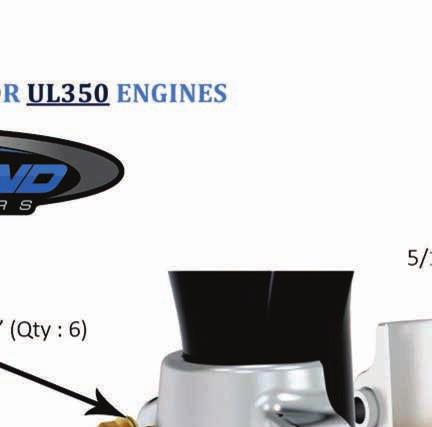
3 Contents WHIRL WIND GROUND ADJUSTABLE (GA) AIRCRAFT PROPELLER... 3 PACKING LIST... 3 ASSEMBLY DIAGRAM FOR UL260 ENGINES... 4 PROPELLER INSTALLATION... 5 TOOLS... 5 ATTACH MOUNTING HUB HALF... 5 INSERT BLADES IN HUB MOUNTING HALF... 6 CHANGING THE PITCH... 6 TACHOMETER INSPECTION:... 7 CONTINUED AIRWORTHINESS REQUIREMENTS:... 8 INSPECTION FOR LIGHTNING STRIKE ON COMPOSITE BLADES INSPECTION AFTER SUSPECTED IMPACT MANDATORY INSPECTIONS: INITIAL 50 HOUR & SUBSEQUENT ANNUAL INSPECTIONS Page 2 of 11
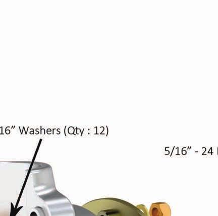
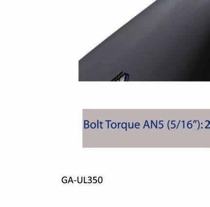
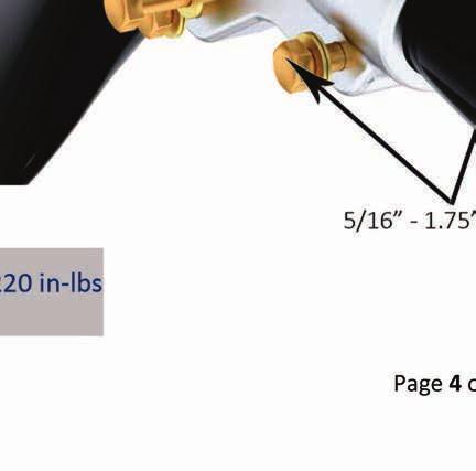
4 WHIRL WIND GROUND ADJUSTABLE (GA) AIRCRAFT PROPELLER CAUTION: Failure to follow these instructions will void all warranties, expressed and implied. Mounting difficulties and increased vibration will result with improper assembly of the propeller blades and hub parts. PACKING LIST (3) Propeller Blades (1) Hub * Front & Rear halves (1) Blade Pitch Paddle Hardware - Mounting Bolts & Washers, for mounting hub on flange 3 5/16" 24 x 4" Bolts Bolt Torque Values: 5/16 0 in-lbs Nord ock Washers

5
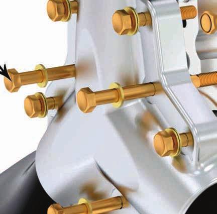
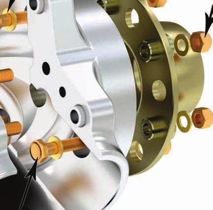
6 PROPELLER INSTALLATION CAUTION: Failure to follow these instructions will void all warranties, expressed and implied. Mounting difficulties and increased vibration will result with improper assembly of the propeller blades and hub parts. TOOLS A good quality calibrated torque wrench is required to properly torque clamping bolts and mounting bolts. You will also need a socket wrench. See Propeller Data Sheet for bolt size and torque. ATTACH MOUNTING HUB HALF 1. Be certain that the magneto switch is OFF and that both magnetos are grounded. Chock the aircraft wheels to prevent movement. Clean dirt and oil residue from the engine flange. 2. Place spacer (if applicable), rear spinner bulkhead, and the hub mount half. The hub and spacer (if applicable) must sit flush on the mounting flange and the rear spinner bulkhead. NOTE: Bolt breakage will occur if not flush. Place special lock washers, under the bolt heads. Each special lock washer works in pairs with the ramped sides facing each other. See Position the hub mount half, rear bulkhead, and spacer (if applicable) on the engine flange with the six mounting bolts running through the engine flange. Torque the 6 mounting bolts using a star pattern similar to Figure 1 below. See Propeller Data Sheet for mounting bolt torques. Figure 1 Page 5 of 11
7 INSERT BLADES IN HUB MOUNTING HALF 3. Each blade has a camber, round side (decal) and a flat side. With the round side facing forward, and the hub in the vertical position, insert one blade at a time into the hub mounting half. You may need to hold the upper blade with one hand. 4. Place the hub clamp half over the blade shanks. Place special lock washers, under the heads, on clamp bolts and insert into the hub cover half. Hand tighten the clamp bolts into the threaded clamp bushings, taking care to maintain an even gap between hub halves on all sides. 5. Using a calibrated torque wrench and following the pattern shown in Figure 1. Tighten the bolts in ¼ to ½ turn increments (this will take several passes) until the proper torque (see Data Sheet) is reached. It is important to maintain an even gap between the hub halves. NOTE: Have your tachometer calibrated by a professional before performing this next operation. With the brakes on, run the engine full throttle to verify your desired static RPM. CAUTION: YOU SHOULD NEVER EXCEED THE MAXIMUM RPM RATING FOR YOUR ENGINE. If you are not seeing your correct static RPM, be certain that the tachometer is properly calibrated. CAUTION: YOU SHOULD NEVER MASK AN ENGINE PROBLEM WITH A PITCH CHANGE. If you are unsure, please contact the factory. CHANGING THE PITCH If changing the pitch is necessary, first loosen the 6 clamp bolts until the blades are loose, then hand tighten the bolts to maintain an even hub gap in each side. (NOTE: The special lock washers will click loudly when loosened) Adjust pitch setting using the blade paddle / protractor to 17 degrees from vertical. Static RPM should be 300 to 400 less than Max engine RPM. Try to set the pitch of each blade within 0.2 degrees of each other. Decrease pitch to increase RPM. Increase pitch to decrease RPM. After the blade angles have been set, torque all bolts as described above. After the correct static RPM is achieved, recheck all bolt torques. Page 6 of 11
8 TACHOMETER INSPECTION: Owing to the exceptionally high stresses that may be generated by particular propeller/engine combinations at certain operating ranges, many propeller and aircraft manufacturers have established revolutions per minute (RPM) restrictions and maximum RPM limits for some models. An improperly operating tachometer can cause an engine to exceed the maximum RPM limits or allow operation unknowingly within a restricted RPM band. Since there are no post-manufacture accuracy requirements for engine tachometers, tachometer inaccuracy could be a direct cause of propeller failure, excessive vibration, or unscheduled maintenance. Proper tachometer operation and accuracy should always be checked (using the manufacturer s procedure, if available) during normal maintenance intervals. One means of checking the tachometer s accuracy is with a commercial strobe unit through which the rotating propeller is viewed. Page 7 of 11
9 CONTINUED AIRWORTHINESS REQUIREMENTS: The following will help you operate your propeller safely, keep it looking good and help it to last Never install a propeller on an aircraft unless it is a model approved for the aircraft and the engine. The service history must be properly documented, and a pre-installation inspection must indicate that the propeller is airworthy. A visual Inspection is the primary defense against early failure of propellers. When inspecting propellers, it is necessary to use touch and hearing, as well as visual clues. Changes in surface roughness, unusual free play, and odd sounds give hints as to conditions that may affect airworthiness. Feel for roughness and look for texture changes, waviness, and changes in reflection that may signal the removal of protective coatings. Some areas may require the use of a 10x magnifying glass to identify small features or find cracking. Do not operate your propeller above the recommended engine RPM. If your propeller has been subjected to an over speed condition of 10% over the maximum rating (example 3300 X 1.1 = 3630) for more than 2 minutes, you must perform the Inspection After Suspected Impact listed below. A 20% overspeed or higher, the propeller must be removed from service. Do not paint over areas of corrosion on hub parts. Do not operate any aircraft after a propeller has been subjected to an impact without a thorough inspection. See Inspection After Suspected Impact below The pre-flight walk-around is an important element of the process of airworthiness maintenance. It should not be merely a superficial look, but a studied review of the condition of everything that might give trouble during the forthcoming flight. Carefully examine the propeller assembly for looseness, any signs of damage, excessive wear or any other condition that would make the propeller unsafe to operate. Check the leading edge for cracks and debonds. Externally check the spinner and bulkhead for security, missing fasteners, damage, and cracks. Cracks typically originate from the attachment screws. Check for looseness of the bulkhead. This could be an indication that the mounting bolts are loose and need to be torqued again. Note any indications in the logbook for future reference to determine whether an acceptable condition is getting worse. Do not use the propeller as a tow-bar to move your aircraft. Apply a good quality automotive paste wax to the blades at least once a year. Avoid running-up in areas containing loose stones, sand, and gravel, to reduce erosion and/or damage to the leading edges and blades. Page 8 of 11
10 Finish loss off the leading edge is a normal wear item and is dependent on the amount of operation in rain and grit. Whenever there is evidence of roughness on operation, check bolt torque on both the clamping and mounting bolts, and check the propeller blades for track. The blades should track within 1/8 of each other at the tip. For new installations, rotating the propeller 180 degrees and reinstalling may help. If the bolts are ever over-torqued, they should be replaced immediately. If your propeller part begins to show any of the following damage, it must be repaired by an approved propeller shop or retired from service: (a) Cracks in the metal hub or bolts, (b) Loose metal leading edge, (c) Any crack across the blade, (d) Any crack along the blade length, (e) Blade impact damage with missing composite material larger than.5 square inches and/or deeper than.025 (f) Obvious damage or wear beyond economical repair. Page 9 of 11
11 INSPECTION FOR LIGHTNING STRIKE ON COMPOSITE BLADES Any Whirl Wind composite blade suspected of lightning strike should be inspected and may require repair or replacement. Lightning strikes usually enter a composite blade through the metal erosion shield. If a lightning strike is present, a darkened area and possible pitting, usually in the proximity of the tip, will be noticeable. If a lightning strike is suspected or detected, consider the blade un-airworthy. Return the blade to the factory or an approved propeller shop for further examination. INSPECTION AFTER SUSPECTED IMPACT Propellers that have been involved in a known or suspected static or rotating impact with relatively solid objects (e.g., ground, maintenance stands, runway lights, birds, etc.) or relatively yielding objects (e.g., snow banks, puddles of water, heavy accumulation of slush, etc.) should be inspected for damage before further flight. If the inspection reveals one or more of the following listed indications, the propeller should be removed and sent to Whirl Wind Propellers for evaluation. (1) A blade that tracks out of limits or out of edge alignment. (2) Loose blades in the hub. (3) Any diameter reduction (tip damage). (4) Visible major damage to the hub that cannot meet the Minor Hub Repairs criteria. (5) Visible major damage to a blade that cannot meet the Minor Blade Repairs criteria. (6) Operating changes, such as vibration or abnormal RPM. NOTE: The bolts should be magnetic particle inspected per STM E 1444 or replaced after any propeller strike. PAINT WEAR ON BLADE: NOTE, wear is inevitable on the metal erosion shield. The wear rate depends on several factors, including high operating RPM s in rain or sandy areas, FOD on taxiways and runways, etc. Page 10 of 11
12 MANDATORY INSPECTIONS: INITIAL 50 HOUR & SUBSEQUENT ANNUAL INSPECTIONS -- To be accomplished by an A&P or IA. 1. Remove Spinner Dome and examine it for damage, and cracks. If necessary, replace the spinner dome. 2. Remove and REPLACE all hub bolts with new bolts. 3. Remove the Hub. Inspect both hub halves for corrosion. 4. Remove each blade and inspect blade shanks for any wear making sure the pin is still tight in the blade. A thorough visual inspection is recommended together with a coin tap inspection of each composite blade, including the metal erosion shield on the leading edge (see AC 43-5). No dents in the metal erosion shield should be deeper than 1/8. No dents should puncture the metal erosion shield. There should be no excessive wear on the leading edge. (If further inspection is required, return the blades to the factory or an approved propeller shop for further examination.) 5. Conditions requiring blade replacement: a) Any hole in hollow blade shell (doesn t apply if a replacement metal erosion shield will cover hole) b) Any crack deeper than.025 c) Any solid tip damage that can t be trimmed off completely 8. Remove the rear spinner bulkhead and examine for missing fasteners, damage, and cracks. If damaged, replace the spinner bulkhead. 9. REPLACE the special lock washers with new lock washers. 10. Reinstall the assembly per the above installation instructions. NOTE: There is no specified overhaul time. The propeller parts are removed from service when they can no longer meet the Continued Airworthiness Requirements. Page 11 of 11
PROPELLER INSTALLATION & OPERATION MANUAL MODEL: GA200CN-3B
 PROPELLER INSTALLATION & OPERATION MANUAL MODEL: GA200CN-3B WHIRLWIND PROPELLERS CORPORATION 1800-C Joe Crosson Drive El Cajon, CA 92020 USA www.whirlwindpropellers.com NOVEMBER 2013 1 of 11 GA200CN-3B
WHIRL WIND PROPELLERS GROUND ADJUSTABLE (GA) AIRCRAFT PROPELLER INSTALLATION AND INSTRUCTIONS GA200CN-O200 CONTINENTAL
 AIRCRAFT PROPELLER INSTALLATION AND INSTRUCTIONS GA200CN-O200 CONTINENTAL") WHIRL WIND PROPELLERS GROUND ADJUSTABLE (GA) AIRCRAFT PROPELLER INSTALLATION AND INSTRUCTIONS GA200CN-O200 CONTINENTAL WHIRLWIND PROPELLERS CORPORATION 1800-C Joe Crosson Drive El Cajon, CA 92020 USA www.whirlwindpropellers.com
WHIRL WIND PROPELLERS GROUND ADJUSTABLE (GA) AIRCRAFT PROPELLER INSTALLATION AND INSTRUCTIONS GA200CN-O200 CONTINENTAL WHIRLWIND PROPELLERS CORPORATION 1800-C Joe Crosson Drive El Cajon, CA 92020 USA www.whirlwindpropellers.com
WHIRL WIND PROPELLERS GROUND ADJUSTABLE (GA) AIRCRAFT PROPELLER INSTALLATION AND INSTRUCTIONS GA200L - 716
 AIRCRAFT PROPELLER INSTALLATION AND INSTRUCTIONS GA200L - 716") WHIRL WIND PROPELLERS GROUND ADJUSTABLE (GA) AIRCRAFT PROPELLER INSTALLATION AND INSTRUCTIONS GA200L - 716 WHIRLWIND PROPELLERS CORPORATION 1800-C Joe Crosson Drive El Cajon, CA 92020 USA www.whirlwindpropellers.com
WHIRL WIND PROPELLERS GROUND ADJUSTABLE (GA) AIRCRAFT PROPELLER INSTALLATION AND INSTRUCTIONS GA200L - 716 WHIRLWIND PROPELLERS CORPORATION 1800-C Joe Crosson Drive El Cajon, CA 92020 USA www.whirlwindpropellers.com
SENSENICH GROUND ADJUSTABLE PROPELLER LOG BOOK
 SENSENICH GROUND ADJUSTABLE AIRCRAFT PROPELLER INSTALLATION AND INSTRUCTIONS FOR CONTINUED AIRWORTHINESS -- 2EK and 2EM6 HUB ASSEMBLY AND SENSENICH GROUND ADJUSTABLE PROPELLER LOG BOOK SENSENICH PROPELLER
GA-UL350-3B Propellers
 Instaation and Operation Instructions ii of ii Contents Propeer Models... 1 Packing List... 1 Required Tools... 2 Instaation... 3 General Propeer Instaation Guidelines... 2 Blade and Hub Assembly... 3
GA-200L-STOL (76-82 )
") GA-200L-STOL (76-82 ) Instaation and Operation Instructions (-616(3/8 ), -716(7/16 ), -816(1/2 )) (12 and 13 Spinners) Lycoming Engines ii of ii Contents Propeer Models... 1 Packing List... 1 Required
GA-200L-STOL (76-82 ) Instaation and Operation Instructions (-616(3/8 ), -716(7/16 ), -816(1/2 )) (12 and 13 Spinners) Lycoming Engines ii of ii Contents Propeer Models... 1 Packing List... 1 Required
GA200L Propeller. Installation and Operation Instructions. (Models: 616, 716, 816) Lycoming Engines
 Lycoming Engines") GA200L Propeer Instaation and Operation Instructions (Models: 616, 716, 816) Lycoming Engines ATTENTION: Failure to foow these instructions wi void a warranties, expressed and implied. Mounting difficulties,
GA200L Propeer Instaation and Operation Instructions (Models: 616, 716, 816) Lycoming Engines ATTENTION: Failure to foow these instructions wi void a warranties, expressed and implied. Mounting difficulties,
Flight Design SENSENICH THREE BLADE COMPOSITE AIRCRAFT PROPELLER INSTALLATION AND OPERATION INSTRUCTIONS FOR ROTAX ENGINES
 Composite Aircraft Propellers 2008 Wood Court Plant City, FL 33563 USA Phone (813)752-3711 Fax (813)752-2818 Http:\\www.sensenichprop.com Flight Design SENSENICH THREE BLADE COMPOSITE AIRCRAFT PROPELLER
GA-RW3B Propellers Installation and Operation Instructions (GA-RW3B-70 and GA-RW3B-STOL75) For Rotax 912 / 914 Engines
 For Rotax 912 / 914 Engines") GA-RW3 Propeers Instaation and Operation Instructions (GA-RW3-70 and GA-RW3-STOL75) For Rotax 912 / 914 Engines ontents Propeer Models... 1 Packing List... 1 Required Tools... 1 Instaation... 2 General
GA-RW3 Propeers Instaation and Operation Instructions (GA-RW3-70 and GA-RW3-STOL75) For Rotax 912 / 914 Engines ontents Propeer Models... 1 Packing List... 1 Required Tools... 1 Instaation... 2 General
GA-RW3B Propellers Installation and Operation Instructions (GA-RW3B-70 and GA-RW3B-STOL75) For Rotax 912 / 914 Engines
 For Rotax 912 / 914 Engines") G-RW3 Propeers Instaation and Operation Instructions (G-RW3-70 and G-RW3-STOL75) For Rotax 912 / 914 Engines ontents Propeer Models... 1 Packing List... 1 Required Tools... 1 Instaation... 2 General Propeer
G-RW3 Propeers Instaation and Operation Instructions (G-RW3-70 and G-RW3-STOL75) For Rotax 912 / 914 Engines ontents Propeer Models... 1 Packing List... 1 Required Tools... 1 Instaation... 2 General Propeer
WHIRLWIND. Owner s Manual Series (Rev ) Serial Number: Manufacture Date: A V I A T I O N Model: WHIRL WIND AVIATION
 Serial Number: Manufacture Date: A V I A T I O N Model: WHIRL WIND AVIATION") WHIRLWIND A V I A T I O N Model: 100-4 Serial Number: 100-4- Manufacture Date: M a nufacturer of Composite Constant Speed P r o pellers Owner s Manual 100-4 Series (Rev 2014-2) WHIRL WIND AVIATION 1419
WHIRLWIND A V I A T I O N Model: 100-4 Serial Number: 100-4- Manufacture Date: M a nufacturer of Composite Constant Speed P r o pellers Owner s Manual 100-4 Series (Rev 2014-2) WHIRL WIND AVIATION 1419
WHIRLWIND. Owner s Manual 151H Series (Rev ) Model: 151H Serial Number: Manufacture Date: A V I A T I O N WHIRL WIND AVIATION
 Model: 151H Serial Number: Manufacture Date: A V I A T I O N WHIRL WIND AVIATION") WHIRLWIND A V I A T I O N M a nufacturer of Composite Constant Speed P r o pellers Model: 151H Serial Number: Manufacture Date: Owner s Manual 151H Series (Rev 2014-2) WHIRL WIND AVIATION 1419 STATE ROUTE
WHIRLWIND A V I A T I O N M a nufacturer of Composite Constant Speed P r o pellers Model: 151H Serial Number: Manufacture Date: Owner s Manual 151H Series (Rev 2014-2) WHIRL WIND AVIATION 1419 STATE ROUTE
WHIRLWIND. Owner s Manual 375RV Series (Rev ) Model: 375RV Serial Number: 375RV- Manufacture Date: A V I A T I O N WHIRL WIND AVIATION
 Model: 375RV Serial Number: 375RV- Manufacture Date: A V I A T I O N WHIRL WIND AVIATION") WHIRLWIND A V I A T I O N M a nufacturer of Composite Constant Speed P r o pellers Model: 375RV Serial Number: 375RV- Manufacture Date: Owner s Manual 375RV Series (Rev 2014-3) WHIRL WIND AVIATION 1419
WHIRLWIND A V I A T I O N M a nufacturer of Composite Constant Speed P r o pellers Model: 375RV Serial Number: 375RV- Manufacture Date: Owner s Manual 375RV Series (Rev 2014-3) WHIRL WIND AVIATION 1419
V HUB INSTALLATION AND OPERATING INSTRUCTIONS
 2008 Wood Court Plant City, FL 33563 USA Phone (813)752-3711 Fax (813)752-2818 http:\\www.sensenich.com Composite Airboat Propellers V HUB INSTALLATION AND OPERATING INSTRUCTIONS CAUTION: Failure to follow
AIRCRAFT PROPELLER MAINTENANCE
 AC 20-37E Date: 9/9/05 ADVISORY CIRCULAR AIRCRAFT PROPELLER MAINTENANCE Flight Standards Service Washington, D.C. Initiated By: AFS-350 Subject: AIRCRAFT PROPELLER MAINTENANCE Date: 9/9/05 Initiated By:
WHIRLWIND. Owner s Manual 400C-M14 Series (Rev ) Model: 400C-M14 Serial Number: Manufacture Date: A V I A T I O N WHIRL WIND AVIATION
 Model: 400C-M14 Serial Number: Manufacture Date: A V I A T I O N WHIRL WIND AVIATION") WHIRLWIND A V I A T I O N M a nufacturer of Composite Constant Speed P r o pellers Model: 400C-M14 Serial Number: Manufacture Date: Owner s Manual 400C-M14 Series (Rev 2014-2) WHIRL WIND AVIATION 1419
WHIRLWIND A V I A T I O N M a nufacturer of Composite Constant Speed P r o pellers Model: 400C-M14 Serial Number: Manufacture Date: Owner s Manual 400C-M14 Series (Rev 2014-2) WHIRL WIND AVIATION 1419
WHIRLWIND. Owner s Manual 200RV Series (Rev ) Model: 200RV Serial Number: 200RV- Manufacture Date: A V I A T I O N WHIRL WIND AVIATION
 Model: 200RV Serial Number: 200RV- Manufacture Date: A V I A T I O N WHIRL WIND AVIATION") WHIRLWIND A V I A T I O N M a nufacturer of Composite Constant Speed P r o pellers Model: 200RV Serial Number: 200RV- Manufacture Date: Owner s Manual 200RV Series (Rev 2014-2) WHIRL WIND AVIATION 1419
WHIRLWIND A V I A T I O N M a nufacturer of Composite Constant Speed P r o pellers Model: 200RV Serial Number: 200RV- Manufacture Date: Owner s Manual 200RV Series (Rev 2014-2) WHIRL WIND AVIATION 1419
WHIRLWIND. Owner s Manual 200C / 400C Series (Rev ) Model: Serial Number: Manufacture Date: A V I A T I O N WHIRL WIND AVIATION
 Model: Serial Number: Manufacture Date: A V I A T I O N WHIRL WIND AVIATION") WHIRLWIND A V I A T I O N M a nufacturer of Composite Constant Speed P r o pellers Model: Serial Number: Manufacture Date: Owner s Manual 200C / 400C Series (Rev 2014-2) WHIRL WIND AVIATION 1419 STATE
WHIRLWIND A V I A T I O N M a nufacturer of Composite Constant Speed P r o pellers Model: Serial Number: Manufacture Date: Owner s Manual 200C / 400C Series (Rev 2014-2) WHIRL WIND AVIATION 1419 STATE
WHIRLWIND. Owner s Manual 400 Rocket Series (Rev ) Model: 400 Rocket Serial Number: Manufacture Date: A V I A T I O N WHIRL WIND AVIATION
 Model: 400 Rocket Serial Number: Manufacture Date: A V I A T I O N WHIRL WIND AVIATION") WHIRLWIND A V I A T I O N M a nufacturer of Composite Constant Speed P r o pellers Model: 400 Rocket Serial Number: Manufacture Date: Owner s Manual 400 Rocket Series (Rev 2014-2) WHIRL WIND AVIATION 1419
WHIRLWIND A V I A T I O N M a nufacturer of Composite Constant Speed P r o pellers Model: 400 Rocket Serial Number: Manufacture Date: Owner s Manual 400 Rocket Series (Rev 2014-2) WHIRL WIND AVIATION 1419
SERVICE BULLETIN HC-SB Propeller - Counterweight Clamp Inspection
 1. Planning Information A. Effectivity HARTZELL PROPELLER INC. (1) Hartzell Propeller Inc. lightweight turbine propellers HC-E5A-2( )/E9193( ) installed on Pilatus PC-21 aircraft are affected by this Service
WHIRLWIND. Owner s Manual 200G-CS & 210 (Rev ) Model: Serial Number: Manufacture Date: A V I A T I O N WHIRL WIND AVIATION
 Model: Serial Number: Manufacture Date: A V I A T I O N WHIRL WIND AVIATION") WHIRLWIND A V I A T I O N M a nufacturer of Composite Constant Speed P r o pellers Model: Serial Number: Manufacture Date: Owner s Manual 200G-CS & 210 (Rev 2014-2) WHIRL WIND AVIATION 1419 STATE ROUTE
WHIRLWIND A V I A T I O N M a nufacturer of Composite Constant Speed P r o pellers Model: Serial Number: Manufacture Date: Owner s Manual 200G-CS & 210 (Rev 2014-2) WHIRL WIND AVIATION 1419 STATE ROUTE
SERVICE LETTER HM-SL-001 Overhaul Periods and Life Limits for Hartzell Propeller Inc. Maritime (Non-Aviation) Propellers
 Propellers") 1. Planning Information A. Effectivity (1) All Hartzell Propeller Inc. and Governors, regardless of installation, are affected by this Service Letter. CAUTION: B. Concurrent Requirements DO NOT USE OBSOLETE
1. Planning Information A. Effectivity (1) All Hartzell Propeller Inc. and Governors, regardless of installation, are affected by this Service Letter. CAUTION: B. Concurrent Requirements DO NOT USE OBSOLETE
FAQ FOR SERVICE BULLETIN SB B
 S E N SENIC H P ROPELLER C O., I NC. AREA CODE 813 PHONE - 752-3711 FAX - 752-2818 2008 WOOD COURT PLANT CITY,FL USA 33563 July 18, 2018 See us on the Web @ www.sensenich.com FAQ FOR SERVICE BULLETIN SB2016-06B
Composite Airboat Propeller Instructions
 Composite Airboat Propeer Instructions WhirlWind composite adjustable airboat propeers offer exceent performance and unsurpassed durability. Every blade is equipped with our strong carbon spar and tough
SERVICE BULLETIN. Fuselage Tail Cone Damage
 Fuselage Tail Cone Damage It has come to our attention that a number of Sportsman tailwheel installations have resulted in crushed and/or delaminated fuselage laminates near the aft tailwheel bracket.
pages 4-1 thru 4-4 pages 4-1 thru 4-4
 HARTZELL PROPELLER INC. One Propeller Place Piqua, Ohio 45356-2634 U.S.A. Telephone: 937.778.4200 Fax: 937.778.4391 MANUAL REVISION TRANSMITTAL Manual (61-00-15) Propeller Owner's Manual and Logbook REVISION
HARTZELL PROPELLER INC.
 HARTZELL PROPELLER INC. One Propeller Place Piqua, Ohio 45356-2634 U.S.A. Telephone: 937.778.4200 Fax: 937.778.4391 MANUAL REVISION TRANSMITTAL Manual (61-00-11) Propeller Owner's Manual and Logbook REVISION
Razor X Propeller (with Circle S Hub) Installation and Operation Instructions
 Installation and Operation Instructions") Razor X Propeer (with Circle S Hub) Instaation and Operation Instructions 1 of 9 Introduction Razor X Propeers WhirlWind Razor X blades offer exceent performance and unsurpassed durability. Every blade
Razor X Propeer (with Circle S Hub) Instaation and Operation Instructions 1 of 9 Introduction Razor X Propeers WhirlWind Razor X blades offer exceent performance and unsurpassed durability. Every blade
INSTRUCTIONS FOR CONTINUED AIRWORTHINESS
 Van Horn Aviation, L.L.C. 1510 W. Drake Drive Tempe, Arizona 85283 INSTRUCTIONS FOR CONTINUED AIRWORTHINESS ICA MANUAL Tail Rotor Blade Assembly 2062200-101/-301 Eligible for Installation on Model 206L4
HARTZELL PROPELLER INC. SERVICE BULLETIN TRANSMITTAL SHEET HC-SB Propeller - Blade, Blade Retention Bearing, and Hub Inspection.
 TRANSMITTAL SHEET May 20, 2013 This page transmits Revision 2 to Service Bulletin. Original Issue, dated September 15/04 Revision 1, dated January 14/05 Revision 2, dated May 20/13 Propeller assemblies
INSTALLATION INSTRUCTIONS
 AUTOMOTIVE PRODUCTS, INSTALLATION INSTRUCTIONS SPORTSMAN WINCH MOUNT GRILLE GUARD / HDX WINCH MOUNT GRILLE GUARD / MAX WINCH MOUNTING SYSTEM APPLICATION: 2016 Chevrolet Silverado 1500 PART NUMBER: 40-93875,
PRO COIL INSTALLATION
 INSTALLATION INSTRUCTIONS 1075 North Ave. Sanger, CA 93657-3539 local: 559-875-0222 fax: 559-876-2259 toll free: 800-445-3767 12463-12464 PRO COIL INSTALLATION 2007 IMPORTANT NOTE THIS KIT GIVES YOU THE
25011 ADJUSTABLE STRUT GMC ENVOY & TRAILBLAZER RAISING AND LOWERING STRUT
 INSTALLATION INSTRUCTIONS 1075 North Ave. Sanger, CA 93657-3539 local: 559-875-0222 fax: 559-876-2259 toll free: 800-445-3767 25011 ADJUSTABLE STRUT 02-07 GMC ENVOY & TRAILBLAZER RAISING AND LOWERING STRUT
Kysor On/Off Rear Air Fan Drive
 . Proper precautions must be taken to prevent personal injury from contact with moving parts, unintended engine start or other hazards present when working with powered equipment. Refer to the vehicle
MANUAL REVISION TRANSMITTAL Manual 181 ( ) Propeller Ice Protection System Component Maintenance Manual Revision 3 dated August 2011
 Propeller Ice Protection System Component Maintenance Manual Revision 3 dated August 2011") HARTZELL PROPELLER INC. One Propeller Place Piqua, Ohio 45356-2634 U.S.A. Telephone: 937.778.4200 Fax: 937.778.4365 MANUAL REVISION TRANSMITTAL Manual 181 (30-60-81) Propeller Ice Protection System Component
HARTZELL PROPELLER INC. One Propeller Place Piqua, Ohio 45356-2634 U.S.A. Telephone: 937.778.4200 Fax: 937.778.4365 MANUAL REVISION TRANSMITTAL Manual 181 (30-60-81) Propeller Ice Protection System Component
Propeller Assembly. 1. General
 Propeller Assembly GENERAL 61-10: PROPELLER ASSEMBLY 1. General The propeller assembly consists of a hollow aluminum hub which supports the propeller blades and also houses the pitch changing mechanism.
INSTRUCTIONS FOR CONTINUED AIRWORTHINESS
 Van Horn Aviation, L.L.C. 1510 W. Drake Drive Tempe, Arizona 85283 INSTRUCTIONS FOR CONTINUED AIRWORTHINESS ICA MANUAL Tail Rotor Blade Assembly 2062200-101/-301 Eligible for Installation on Model 206A/B
CHAPTER 64 TAIL ROTOR. Section Title Page
 CHAPTER 64 TAIL ROTOR Section Title Page 64-00 Description........................................ 64.1 64-10 Tail Rotor Assembly.................................. 64.1 64-11 Static Balance..............................
SERVICE MANUAL for. Engine-to-Generator. Part Number used on. John Deere Engine Driven Aircraft Ground Power Single-Bearing Generator Sets
 TO-216 SERVICE MANUAL for Engine-to-Generator FLEXIBLE COUPLING Part Number 181267 used on John Deere Engine Driven Aircraft Ground Power Single-Bearing Generator Sets manufactured by HOBART BROTHERS COMPANY
INSTALLATION INSTRUCTIONS
 INSTALLATION INSTRUCTIONS 1075 North Ave. Sanger, CA 93657-3539 local: 559-875-0222 fax: 559-876-2259 toll free: 800-445-3767 av1075 North Ave Sanger, CA 93657-3539 local: 559-875-8883 fax: 559-875-9883
HARTZELL PROPELLER INC.
 HARTZELL PROPELLER INC. One Propeller Place Piqua, Ohio 45356-2634 U.S.A. Telephone: 937.778.4200 Fax: 937.778.4391 MANUAL REVISION TRANSMITTAL Manual (61-00-49) Propeller Owner's Manual and Logbook REVISION
Section Periodic Inspection and Lubrication (At First 25 Hours, First 50 Hours, First 100 Hours and Subsequently at 100-Hour Intervals)
") Airmaster Propellers Ltd Variable Pitch Constant Speed Propellers for Light Aircraft Airmaster Propellers Ltd Unit B, 144 Central Park Dr PO Box 21220, Henderson Auckland, New Zealand Ph: +64 9 8360065
Airmaster Propellers Ltd Variable Pitch Constant Speed Propellers for Light Aircraft Airmaster Propellers Ltd Unit B, 144 Central Park Dr PO Box 21220, Henderson Auckland, New Zealand Ph: +64 9 8360065
AIRTEK for Mack Vehicles Single to Dual Height Control Valve Conversion Kit
 Single to Dual Height Control Valve Conversion Kit SUBJECT: Kit Nos.60961-128 and 60961-129 LIT NO: 59310-030 DATE: April 2006 REVISION: A INTRODUCTION As of March 2006 all of Mack vehicles will be equipped
Damage Detection and Characterization
 Damage Detection and Characterization Presenter: Peter Smith Damage Detection and Characterization Recognize Composite Damage Types and Sources (Module D) Describe Composite Damage and Repair Inspection
INSTRUCTIONS FOR CONTINUED AIRWORTHINESS
 INSTRUCTIONS FOR CONTINUED AIRWORTHINESS for GROVE MODEL 40-108 & 40-208 MAIN WHEELS DOCUMENT 12012-12 REV IR January 16, 2012 TABLE OF CONTENTS SECTION PAGE Title Page...1 Table of Contents...2 Record
HARTZELL PROPELLER INC.
 HARTZELL PROPELLER INC. One Propeller Place Piqua, Ohio 45356-2634 U.S.A. Telephone: 937.778.4200 Fax: 937.778.4391 MANUAL REVISION TRANSMITTAL Manual (61-00-39) Propeller Owner's Manual and Logbook REVISION
MANDATORY SERVICE BULLETIN The Subject Matter of this Service Bulletin is Incorporated In Whole or in Part in an FAA Airworthiness Directive
 TELEDYNE CONTINENTAL AIRCRAFT ENGINE MANDATORY SERVICE BULLETIN The Subject Matter of this Service Bulletin is Incorporated In Whole or in Part in an FAA Airworthiness Directive SUBJECT: MAGNETO TO ENGINE
1) Scheduled maintenance checks
 Scheduled maintenance checks") 1) Scheduled maintenance checks Definition This section lists the periodic inspections which must be carried out after a specified periods of operation. Intervals Periodic inspections are those which must
1) Scheduled maintenance checks Definition This section lists the periodic inspections which must be carried out after a specified periods of operation. Intervals Periodic inspections are those which must
MANDATORY SERVICE BULLETIN
 652 Oliver Street Williamsport, PA 17701 U.S.A. Tel. 1 800 258 3279 (U.S. and Canada) Tel. 1 570 323 6181 (International) Fax. 1 570 327 7101 www.lycoming.com MANDATORY SERVICE BULLETIN DATE: October 4,
AIRTEK for Volvo Vehicles Single to Dual Height Control Valve Conversion Kit
 Single to Dual Height Control Valve Conversion Kit SUBJECT: 60961-101 and 60961-102 LIT NO: 59310-026 DATE: January 2006 REVISION: A INTRODUCTION Prior to March 2005, some Volvo vehicle configurations
Accident Prevention Program
 Accident Prevention Program Maintenance Aspects of Owning Your Own Airplane Introduction As an owner-pilot, FAR Part 43 allows you to perform certain types of inspections and maintenance on your airplane.
SERVICE LETTER. Model 1A162 Propeller, and the McCauley Fixed Pitch Propeller Service Manual.
 September 4, 2009 TITLE MODEL 1A162/TCD6754 PROPELLER SERVICE INFORMATION UPDATE TO: FAA-Approved Propeller Repair Stations, Aircraft Manufacturers, Owners and Operators EFFECTIVITY Model 1A162 Propeller,
Disc Couplings DI Style (6-Bolt) Installation Guide
 Installation Guide") Disc Couplings DI Style (6-Bolt) Installation Guide 1.0 INTRODUCTION: The following document is intended for the explicit use of Lovejoy customers to aid in the installation of Lovejoy power transmission
Disc Couplings DI Style (6-Bolt) Installation Guide 1.0 INTRODUCTION: The following document is intended for the explicit use of Lovejoy customers to aid in the installation of Lovejoy power transmission
INSTALLATION, OPERATION, AND MAINTENANCE MANUAL RBK FRP FAN
 Bulletin 62-January-20-09 ROOF UPBLAST & SIDEWALL CENTRIFUGAL FIBERGLASS EXHAUST FAN INSTALLATION, OPERATION, AND MAINTENANCE MANUAL RBK FRP FAN The M.K. Plastics catalog on the above corrosion resistant
STOP. Broadcast Spreader. Operator's Manual. Model No Safety Assembly Operation Maintenance Parts
 Operator's Manual STOP Broadcast Spreader Model No. 486.2400 DO NOT RETURN TO STORE For Missing Parts or Assembly Questions Call 1-866-56-8388 CAUTION: Before using this product, read this manual and follow
with Instruction Manual
 with Instruction Manual No. BAGU - 5 Lap Belt Assembly BAGU 5000 - series in combination with Shoulder Harness Assembly SCHUGU 2000 - series and Crotch Strap Assembly BOGU 1000 - series Maintenance procedures
Kit No Please read these instructions completely before proceeding with installation. Air Spring Kit Parts List. Bracket Attaching Hardware
 Kit No. 59537 MN-461 (021108) ECR 7136 Please read these instructions completely before proceeding with installation Air Spring Kit Parts List Item Description Quantity A Air Sleeves 2 B Upper Brackets
INSTALLATION, OPERATION, MAINTENANCE MANUAL FOR MANUALLY OPERATED STOP CHECK VALVE
 INSTALLATION, OPERATION, MAINTENANCE MANUAL FOR MANUALLY OPERATED STOP CHECK VALVE Page 1 of 13 1.1 General CHAPTER 1 - GENERAL INFORMATION This manual contains maintenance instructions with pertinent
Kits (53mm), (48.5mm)
, (48.5mm)") Kits 78570 (53mm), 78571 (48.5mm) Audi B9 Front Application MN-1073 (011808) ERN 8788 INSTALLATION GUIDE For maximum effectiveness and safety, please read these instructions completely before proceeding
Kits 78570 (53mm), 78571 (48.5mm) Audi B9 Front Application MN-1073 (011808) ERN 8788 INSTALLATION GUIDE For maximum effectiveness and safety, please read these instructions completely before proceeding
/ Marley HP7000 Fan / User Manual B
 / Marley HP7000 Fan / User Manual 97-1342B Fan Components 300 174 173 172 45 ft lbƒ (61 N m) 171 101 122 121 150 ft lbƒ (204 N m) 123 HUB ASSEMBLY IDENTIFICATION NUMBER 140 SEE FIG 6 FOR DETAILS 15 ft
INSTRUCTIONS FOR CONTINUED AIRWORTHINESS
 Van Horn Aviation, L.L.C. 1510 W. Drake Drive Tempe, Arizona 85283 INSTRUCTIONS FOR CONTINUED AIRWORTHINESS ICA MANUAL Main Rotor Blade Assembly 20631000-101 Eligible for Installation on Model 206B VAN
Kysor On/Off Rear Air Fan Drive
 . Proper precautions must be taken to prevent personal injury from contact with moving parts, unintended engine start, or other hazards present when working with powered equipment. Refer to the vehicle
Maintenance Information
 16573370 Edition 2 February 2014 Air Grinder 99V Series Maintenance Information Save These Instructions Product Safety Information WARNING Failure to observe the following warnings, and to avoid these
INSTALLATION INSTRUCTIONS
 AUTOMOTIVE PRODUCTS, INSTALLATION INSTRUCTIONS HDX DROP STEP APPLICATION: 2007-2017 Chevy Silverado / GM Sierra / 1500-2500-3500 Ext. / Double / Crew Cab PART NUMBER: 56-13715, 56-13725 ITEM QUANTITY DESCRIPTION
READ AND UNDERSTAND THIS MANUAL AND ALL INSTRUCTIONS
 DR WALK-BEHIND LEAF & LAWN VACUUM OPTIONAL VACUUM HOSE ACCESSORY SAFETY & OPERATING INSTRUCTIONS READ AND UNDERSTAND THIS MANUAL AND ALL INSTRUCTIONS BEFORE USING YOUR NEW HOSE ACCESSORY. and congratulations
EIS Instructions for Continued Airworthiness
 EIS-61000 Instructions for Continued Airworthiness Electroair 317 Catrell Dr, Suite #2 Howell, MI 48843 U.S.A. Ph: 517-552-9390 Fax: 517-552-9391 Email: sales@electroair.net Electroair Acquisition Corp.
PIPER AIRCRAFT PA NOTE- Perform all inspections or operations at each oj the inspection. 1. Inspectspinnerandbackplate
 PPER ARCRAFT PA-38-111 (.MANTENANCE MANUAL SCHEDULED MANTENANCE. PERODC NSPECTONS. -NOTE- Perform all inspections or operations at each oj the inspection intervals as indicated by a circle (). nspection
INSTALLATION SHEET. PARTS INCLUDED IN YOUR KIT 1 Pair rails (L&R) Roll top assembly Bulkhead seals (1x 1/4 & 1x 3/4 thick) (1x 1/4 & 1x 1/4 thick)
 Roll top assembly Bulkhead seals (1x 1/4 & 1x 3/4 thick) (1x 1/4 & 1x 1/4 thick)") INSTALLATION SHEET Any damaged or missing parts? Parts will be shipped to you directly. Call 844-779-8986 Mon - Fri 8:30 am - 7 pm EST or email support@bakindustries.com TOOLS RECOMMENDED 9/16 Wrench or
INSTALLATION SHEET Any damaged or missing parts? Parts will be shipped to you directly. Call 844-779-8986 Mon - Fri 8:30 am - 7 pm EST or email support@bakindustries.com TOOLS RECOMMENDED 9/16 Wrench or
Installation Manual. 3 suspension system Toyota Tacoma 4WD & 2WD prerunner. Part # Part # Important customer information:
 Installation Manual 3 suspension system 2005-2018 Toyota Tacoma 4WD & 2WD prerunner Part # 53908 SS03012017 Part # 53908 2007-2018 Toyota Tacoma 4WD & 2WD Prerunner 3 Suspension System (no strut disassembly)
JABIRU AIRCRAFT PTY LTD P.O. Box 5186 Phone: Bundaberg West Fax: Queensland, Australia.
 JABIRU AIRCRAFT PTY LTD P.O. Box 5186 Phone: +61 7 4155 1778 Bundaberg West Fax: +61 7 4155 2669 Queensland, Australia. Email: info@jabiru.net.au SERVICE BULLETIN: JSB 014-1 Issue: 1 Date: 30 th October
SECTION 3. EXHAUST SYSTEMS
 9/8/98 AC 43.13-1B 8-45. GENERAL. Any exhaust system failure should be regarded as a severe hazard. Depending upon the location and type of failure, it can result in carbon monoxide (CO) poisoning of crew
Maintenance Information
 80234313 Edition 1 June 2006 Air Grinder, Die Grinder, Sander and Belt Sander Series G1 (Angle) Maintenance Information Save These Instructions WARNING Always wear eye protection when operating or performing
CIRRUS AIRPLANE MAINTENANCE MANUAL
 UNSCHEDULED MAINTENANCE CHECKS 1. DESCRIPTION The following describes those maintenance checks and inspections on the aircraft which are dictated by special or unusual conditions which are not related
1.1 Quad Valve and Tri-Valve. Contents WATER DUMP BODY O-RING EXHAUST VALVE QUAD VALVE TIE WRAP EXHAUST MAIN BODY O-RING
 Quad Valve and Tri-Valve Exhaust Assembly on Fiberglass Helmets Quad Valve and Tri-Valve Exhaust Contents QUAD-1 QUAD-2 QUAD-2 QUAD-2 QUAD-6 QUAD-7 1.1 Quad Valve and Tri- Valve Exhaust Assembly on Fiberglass
Unscheduled Maintenance Checks
 CIRRUS AIRPLANE MAINTENANCE MANUAL CHAPTER 5-50: UNSCHEDULED MAINTENANCE CHECKS GENERAL Unscheduled Maintenance Checks 5-50: UNSCHEDULED MAINTENANCE CHECKS 1. General The following describes those maintenance
Maintenance Information
 16573347 Edition 2 February 2014 Air Grinder Series 88H Maintenance Information Save These Instructions Product Safety Information WARNING Failure to observe the following warnings, and to avoid these
Copyright 1998 Inter-Industry Conference On Auto Collision Repair v.4.0
 Uniform Procedures For Collision Repair HO21S Hood 1. Description This procedure describes the repair and replacement of a steel hood. Inspection and evaluation requirements are also included. 2. Purpose
HARTZELL PROPELLER INC. ACTIVE SERVICE INSTRUCTION INDEX - February 09, 2018 (excluding HD series propeller and systems)
") 1A 09/23/75 Installation of C-2052, C-2052-1, or C-2052-3 Governor and T Drive Kit on Bonanza. 2 03/01/55 Installation of Tee Drive C-192-2 for hydraulic & vacuum pump. 3 12/01/52 Installation of HC-12X20-8/8428
1A 09/23/75 Installation of C-2052, C-2052-1, or C-2052-3 Governor and T Drive Kit on Bonanza. 2 03/01/55 Installation of Tee Drive C-192-2 for hydraulic & vacuum pump. 3 12/01/52 Installation of HC-12X20-8/8428
3.2 DRIVE TORQUE HUB. Roll, Leak and Brake Testing SECTION 3 - CHASSIS & TURNTABLE. 3-2 JLG Lift
 3.2 DRIVE TORQUE HUB Roll, Leak and Brake Testing 10 LUG PATTERN Torque-Hub units should always be roll and leak tested before disassembly and after assembly to make sure that the unit's gears, bearings
REPORT IN-042/2006 DATA SUMMARY
 REPORT IN-042/2006 DATA SUMMARY LOCATION Date and time Friday, 14 July 2006; 13:15 h local time 1 Site Borjas Blancas (Lleida) AIRCRAFT Registration Type and model Operator EC-JCQ TECNAM P2002-JF Private
Kit No Please read these instructions completely before proceeding with installation. Air Spring Kit Parts List. Attaching Hardware
 Kit No. 57340 MN-431 (02409) NPR 4796 Please read these instructions completely before proceeding with installation by www.airliftcompany.com Air Spring Kit Parts List A B1 B2 Item Description Quantity
MS2200, MS2500, and MS3000 Suspension Installation Manual ON/OFF HIGHWAY SUSPENSION SYSTEM
 MS22, MS25, and MS3 Suspension Installation Manual ON/OFF HIGHWAY SUSPENSION SYSTEM 972.547.62 8.445.736 FAX: 972.542.97 725 E. UNIVERSITY ST. McKINNEY, TEXAS 7569 www.watsonsuspensions.com Watson & Chalin
INSTALLATION INSTRUCTIONS
 INSTALLATION INSTRUCTIONS --1075 North Ave. Sanger, CA 93657-3539 local: 559-875-0222 fax: 559-876-2259 toll free: 800-445-3767-- 2511 2 DROP SPINDLE 2WD (Must Use 17 or larger wheels AND be used for 3+
SERVICE BULLETIN HC-SB Propeller - Blade Bearing Race Inspection Criteria
 1. Planning Information A. Effectivity (1) All Hartzell Propeller Inc. aluminum hub compact propeller models HC-( )( )Y( )-( ) are affected by this Service Bulletin. (2) All Hartzell Propeller Inc. aluminum
Maintenance Information
 80234313 Edition 2 May 2014 Air Grinder, Die Grinder, Sander and Belt Sander Series G1 (Angle) Maintenance Information Save These Instructions Product Safety Information WARNING Failure to observe the
(877) MON-FRI 7AM-5PM PST OR WEBSITE: ReadyLIFT.COM **Please retain this document in your vehicle at all times**
 MON-FRI 7AM-5PM PST OR WEBSITE: ReadyLIFT.COM **Please retain this document in your vehicle at all times**") IF your ReadyLIFT product has a damaged or missing part, please contact customer service directly. For warranty issues please return to the place of installation and contact ReadyLIFT. A NEW REPLACEMENT
IF your ReadyLIFT product has a damaged or missing part, please contact customer service directly. For warranty issues please return to the place of installation and contact ReadyLIFT. A NEW REPLACEMENT
Kits (with shocks), (no shocks) Audi B9
, (no shocks) Audi B9") Kits 78670 (with shocks), 78671 (no shocks) Audi B9 Rear Application MN-1074 (011808) ERN 8788 INSTALLATION GUIDE For maximum effectiveness and safety, please read these instructions completely before
Kits 78670 (with shocks), 78671 (no shocks) Audi B9 Rear Application MN-1074 (011808) ERN 8788 INSTALLATION GUIDE For maximum effectiveness and safety, please read these instructions completely before
MANUAL REVISION TRANSMITTAL Manual 147 ( ) Propeller Owner's Manual and Logbook REVISION 13 dated July 2017
 Propeller Owner's Manual and Logbook REVISION 13 dated July 2017") HARTZELL PROPELLER INC. One Propeller Place Piqua, Ohio 45356-2634 U.S.A. Telephone: 937.778.4200 Fax: 937.778.4215 MANUAL REVISION TRANSMITTAL Manual (61-00-47) Propeller Owner's Manual and Logbook REVISION
HARTZELL PROPELLER INC. One Propeller Place Piqua, Ohio 45356-2634 U.S.A. Telephone: 937.778.4200 Fax: 937.778.4215 MANUAL REVISION TRANSMITTAL Manual (61-00-47) Propeller Owner's Manual and Logbook REVISION
18 KG MOBILE SODA BLASTING UNIT
 OWNER S MANUAL PRODUCT CODE: 3043 18 KG MOBILE SODA BLASTING UNIT Working Air Hose Tank Volume Overall Dimensions Pressure Consumption Length 18KG 35 90psi 6-12CFM 2400mm 460 x 305 x 660 Made in China
Kit No Please read these instructions completely before proceeding with installation. Parts List G J I K L H CC FF DD MN-505 (01201) NPR 3733
 NPR 3733") Kit No. 57154 MN-505 (01201) NPR 3733 Please read these instructions completely before proceeding with installation Parts List by www.airliftcompany.com Item P/N Description Quantity A 58407 Air Spring
Kit No. 57154 MN-505 (01201) NPR 3733 Please read these instructions completely before proceeding with installation Parts List by www.airliftcompany.com Item P/N Description Quantity A 58407 Air Spring
INSTRUCTION MANUAL For Turbo Unit The Unit for The Electric-Power Assist Intelligent Bike Sunstar Engineering Inc.
 INSTRUCTION MANUAL For Turbo Unit The Unit for The Electric-Power Assist Intelligent Bike For your safety, make sure to read this instruction manual before using the unit and understand the contents thoroughly.
DynaVibe Procedure for Aircraft Propellers
 Application Note: RPX-AFA-PR-BAL-00-A September 2016 This application note is for reference only and does not modify, replace, substitute for, or supersede official regulations or the aircraft manufacturer
INSTALLATION INSTRUCTIONS
 AUTOMOTIVE PRODUCTS, INSTALLATION INSTRUCTIONS SPORTSMAN GRILLE GUARD / HDX GRILLE GUARD APPLICATION: 2016 Chevrolet Silverado 1500 PART NUMBER: 40-3875, 45-3870, 57-3870, 57-3875 ITEM QUANTITY DESCRIPTION
BU01S Bumper. Copyright 1998 Inter-Industry Conference On Auto Collision Repair v.4.0
 Uniform Procedures For Collision Repair BU01S Bumper 1. Description This procedure describes the replacement of a steel bumper. Inspection and evaluation requirements are also included. 2. Purpose The
Kysor Rear Air Fan Drives
 On/Off Technology for Heavy-Duty Truck Applications Installation & Service Guide Kysor Rear Air Fan Drives thermal.borgwarner.com For Additional BorgWarner Thermal Systems Information: 800-927-7811 USA
SAMPLE BLUE STAR CONVERSION INSTALLATION OF CONTINENTAL IO-470-N BEECH MODEL J35, K35, M35 LWS C-470-N. REVISION 2. September 16, 1992 STC SA5635SW
 BLUE STAR CONVERSION INSTALLATION OF CONTINENTAL IO-470-N BEECH MODEL J35, K35, M35. REVISION 2 September 16, 1992 STC SA5635SW SAMPLE 1 1992SAMPLE BLUE STAR CONVERSION Table of Contents Page Description
Rolls -Royce M250--B17 SERIES OPERATION AND MAINTENANCE. Table 602 Inspection Checksheet Owner Date. A/C Make/Model S/N Reg No.
 Table 602 Inspection Checksheet Owner Date A/C Make/Model S/N Reg No. TSN Engine S/N TSN TSO This inspection checksheet is to be used when performing scheduled inspections. This form can be locally reproduced
DISC AND ELECTRIC BRAKE MAINTENANCE
 Purpose To maintain and extend the product life of the Disc Brake and Electric Brake product lines. Safety Failure to follow the instructions provided in this manual may result in death, serious personal
INSTALLATION SHEET. PARTS INCLUDED IN YOUR KIT 1 Pair rails (L&R) Roll top assembly Bulkhead seals (1x 1/4 & 1x 3/4 thick) (1x 1/4 & 1x 1/4 thick)
 Roll top assembly Bulkhead seals (1x 1/4 & 1x 3/4 thick) (1x 1/4 & 1x 1/4 thick)") INSTALLATION SHEET Any damaged or missing parts? Parts will be shipped to you directly. Call 818-365-9000 Mon - Fri 8:00 am - 4 pm Pacific Time or email support@bakindustries.com TOOLS RECOMMENDED 9/16
INSTALLATION SHEET Any damaged or missing parts? Parts will be shipped to you directly. Call 818-365-9000 Mon - Fri 8:00 am - 4 pm Pacific Time or email support@bakindustries.com TOOLS RECOMMENDED 9/16
GP314S-C CERAMIC HEADER
 GP314S-C CERAMIC HEADER 04-06 DODGE MAGNUM RT 5.7L HEMI 2WD 04-06 CHRYSLER 300 C STYLE 5.7L HEMI AWD 2006 DODGE CHARGER 5.7L HEMI 2WD GIBSON HEADERS ARE 50 STATE SMOG LEGAL AUTOMATIC ONLY Thank you very