LG Alert TM Helping Drivers Operate Safely. LG Alert Lateral Acceleration Indicator User / Installation Manual
|
|
|
- Oscar Paul
- 5 years ago
- Views:
Transcription


1 INTRODUCTION US Pat. No. 6,130,608 The is intended for use as an early alert system to assist drivers in recognizing when they are exceeding set maximum maneuvering limits of the vehicle. The device monitors and displays lateral g-forces perpendicular to the vehicle direction and travel in real time. The lateral sensitivity of the device can be adjusted using the digital push buttons on the front of the base unit. 00 is the least sensitive setting and 99 is the most sensitive setting. An auxiliary horn jack provides additional signals indicating the full scale of the device has been exceeded, in addition to signal output jacks providing voltages biased at +2.5 VDC proportional to applied g-forces for data logging or trip recording applications. Internal filtering reduces the effects of high frequency accelerations associated with bumps and vibration. OPERATING PRINCIPLE The foundation of the is a complete acceleration measurement system contained in a hermetically sealed monolithic IC. The signal conditioning circuitry incorporates a force balance control loop and bias adjustment to center the signal about zero. This provides a bi-polar voltage proportional to the applied g-force. The value of the lateral signal is determined and output to the display module, with lateral g-force to the left displayed as an increasing level on the right, and vice versa for a right increasing lateral g-force. Internal temperature regulation of sensitive IC s virtually eliminates error associated with changes in surrounding temperature. The device can be set to display a full-scale lateral acceleration range between 0.17 and 1 g-force. The includes the following standard components: Display Assembly Base Assembly Mounting Bracket Assembly Display Cable Assembly (10 ft.) Power Cable Assembly (10 ft.) Remote Horn Assembly LG Alert TM Helping Drivers Operate Safely Note: Units for large fleet orders may be provided with custom cable lengths and mounting brackets. The requires 12 ± 3 VDC input for standard operation. If the power available is out of the 12 VDC range, an optional power supply is available that will accommodate a 9 to 36 VDC input providing a 12 VDC output to the LG Alert. OPTIONAL POWER SUPPLY Power Supply Power Supply Input Cable (10ft) Power Supply Output Cable (10ft) Page 1

 R = radius of turn (m) V = velocity (m/s) F = force (N) m = mass (kg) Constants: Force of")
2 THEORETICAL PRINCIPLES LATERAL FORCES ON A VEHICLE Turning a corner results in a momentum force perpendicular to the vehicle center line. This is known as a lateral g-force or lateral acceleration. When these lateral forces become large enough, the vehicle will either slide or overturn. This condition is referred to as a rollover. Lateral forces on a vehicle can be determined by the summation of radial acceleration associated with turning a corner and the tilt component related to the force of gravity on the vehicle. LATERAL g FORCE CALCULATION WHEN TURNING A CORNER R FORMULA: a = V 2 /R Values: a = acceleration (m/s 2 ) R = radius of turn (m) V = velocity (m/s) F = force (N) m = mass (kg) Constants: Force of gravity = 9.81 m/s 2 a v EXAMPLE: Turning Radius (R) = 50m Velocity (V) = 40 km/h a = (40km/hr x 1000m / 3600s) 2 / 50 a = m/s 2 g = (2.469 m/s 2 ) / (9.81 m/s 2 ) g = 0.25 FORCES ON AN INCLINED SURFACE Acceleration = SIN (tilt angle) x 9.81 m/s 2 The displays the total lateral acceleration on the vehicle, which is the sum of the turning acceleration and the component associated with gravity. (E.g. from an inclined surface) Lateral g-forces on the right of the vehicle are displayed on the left-hand side, and lateral g-forces on the left of the vehicle are displayed on the right-hand side of the indicator display. A tilt table can be used to establish a safe setting for the. The relationship between digital setting and full-scale sensitivity is shown in the set up table. Alternatively, the device can be set by an experienced driver and tested under actual vehicle operating conditions to determine a setting. Page 2

3 INSTALLATION LOCATION Both base and display modules should be located within the driver compartment. The display module can be positioned anywhere that is convenient for viewing by the vehicle operator. The SAE suggests instruments should be located 0.71 m (28 in) from the driver s eye no more than 45 degrees below the horizon and within 30 degrees from straight-ahead. The base module should be positioned as low in the cab as possible using the10 ft. cable provided. It must be firmly attached to the vehicle framework and as close to level as possible. Access to the base unit s front panel should not be obstructed to allow access in case of sensitivity setting adjustment. The front and rear panels of the base unit must be aligned with the vehicle forward direction of travel. Cables should be located away from contact by people and equipment and secured to reduce fatigue due to vibration. ATTENTION: ORIENTATION OF LG-ALERT TM IN THE CAB OF THE VEHICLE IS CRITICAL TO THE PROPER OPERATION OF THE DEVICE. ENSURE THAT THE SELECTOR SWITCH IS SET AS INDICATED BELOW. Selector Switch Front of unit facing forward in vehicle: SWITCH DOWN (as shown) Front Front View (Cover Removed) Front of unit facing rearward in vehicle: SWITCH UP LOCATIONS TO AVOID The display module can be placed in almost any location convenient for viewing by the vehicle operator. The device, however, should not be located where it may obstruct the vehicle operator s visibility. The base module must be protected from transient conditions and impact. Do not locate the device in an area that may be exposed to the weather. Do not locate in areas of high humidity or temperature extremes (E.g. engine compartment) Do not locate in areas exposed to turbulent air from fans, doors or windows Do not locate in areas exposed to high electromagnetic interference Do not locate in areas that may allow impact from people or equipment Do not route cables through areas of high electrical magnetic interference. Page 3
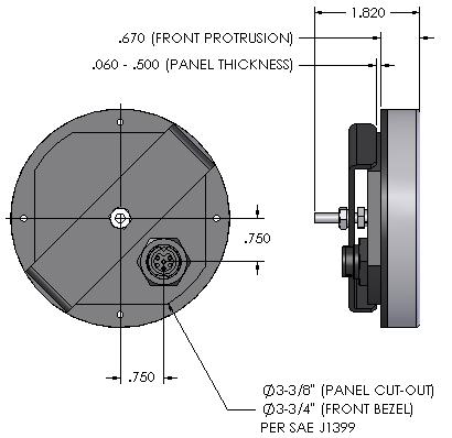
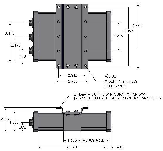
4 DIMENSIONS Page 4


5 WIRING The LG-Alert requires only two (2) cables to be connected to function. One cable provides 12 VDC from the vehicle fuse panel, and is connected to the Base Assembly rear connector, labeled 12 VDC. The second cable connects the Display Assembly to the Base Assembly. It is connected on one end to the Display Assembly rear connector, and the other end connects to the Base Assembly rear connector, labeled DISPLAY. An internal fast blow fuse provides protection for the device. The power lights on both the Base and Display units should illuminate upon powering the unit. There is a warm up period of approximately 120 seconds where the device may display imbalance. During installation, the device can be tested for functionality by attaching cables and rotating the base module as shown. Rotate as shown to test functionality Connect to +12VDC ignition switched source Connect to negative chassis ground Remote Horn Connects to HORN/SIG (installation optional) Page 5
6 TROUBLE SHOOTING NO POWER Check fuse and power connections Base and Display units should have all power lights illuminated If the lights are not illuminated, the device may malfunction Check the supply voltage to the device. Voltages less than 9 VDC or greater than 15 VDC are outside the device specification range and may cause false readings. Abnormal supply voltage fluctuations caused by faulty equipment or loose wires may cause the highly sensitive amplifier circuits to give a false reading, or appear unbalanced. For voltage ranges of 9 to 36 VDC, an optional power supply is available. See information on Page 1. UNBALANCED OPERATION The device may have shifted during service or the characteristics of the vehicle may change over time causing the device to be out of balance. This error can be removed by zeroing the device. This is accomplished using the adjustment screw on the lower front panel of the base unit, after removing the front cover. If the left and right balance of the device cannot be corrected with the zero adjust, the device may require servicing. ZEROING THE DEVICE The device can be zeroed using a tiny 1/16 flat screwdriver to turn the zero adjust screw found inside the front panel of the base module. The cover must be removed to obtain access to the zero adjustment screw. Make sure the vehicle is on a level surface before starting. Count the rotations of the zero adjustment screw between one indicator light on the display for left and right lateral accelerations. For example, turn the zero adjustment screw until only one green light is illuminated on the display module. Count the number of turns required to pass through zero and illuminate one light the other way. Simply divide the number of turns by two and rotate adjustment pot to the middle point, which should be close to zero. A setting of 99 on the sensitivity adjust digital push button will provide the maximum gain to easily visualize the error. Make sure the device is re-set back to its original digital push button setting after zeroing. Power Indicator Light Zero Adjust Screw Front View (Cover Removed) Self Test Pushbutton Page 6
. The device may be adjusted by removing the base unit front panel and changing the digital setting.")

7 SET UP OF THE LG-ALERT The lateral acceleration indicator is factory set at a digital setting of 55 corresponding to the first alert occurring at a static tilt angle of approximately 15 degrees (0.26 g s). The device may be adjusted by removing the base unit front panel and changing the digital setting. Static tilt table specifications from the factory may be different than the as equipped configuration of the vehicle. The dynamic response of the vehicle is highly unpredictable and can have a profound effect on stability. Vehicle characteristics and response of the LG-Alert define the recommended setting as described in the NRC report to Transport Canada Development of a Training Program for Drivers of High Capacity, High Center of Gravity Airport Rescue and Fire Fighting (ARFF) Vehicles, Dec 10, Management may choose a sensitivity that is even more conservative. Once a setting for a vehicle has been established, management must put in place a clear policy that the device is never altered. Any change in device setting must be clearly documented and all personnel informed especially if the device is rendered less sensitive. A routine inspection of the device setting and operation should be included in the short test drive undertaken at the beginning of each shift. The self-test button can be pressed to ensure the device is fully operational by removing the front panel screw, and inserting a small wire to activate the switch. The relationship between LG-Alert TM digital setting and the associated g forces to activate each of the three warning stages (indicator lights 8,9 and 10) is shown below. Power Indicator Light Green LED s (10% to 60% of full-scale g force) Yellow LED s (70% to 80% of full-scale g force) Red LED s (90% to 100% of full-scale g force) Digital Sensitivity Adjustment 00 to 99 (Refer to chart) Front View (Cover Removed) Page 7
8 LG-ALERT SENSITIVITY TABLE Digital Push Button Setting indicator light 8 is on at (deg) Lateral Tilt Angle indicator light 9 is on at (deg) indicator light 10 is on at (deg) indicator light 8 g forces Lateral Acceleration indicator light 9 g forces indicator light 10 g forces Page 8
9 LIMITATIONS OF LG ALERT This device is intended as an early alert system to assist drivers in recognizing when they are approaching maneuvering limits that are potentially unstable. While this device can provide invaluable information to the operator of the vehicle, it must be recognized that the has limitations. The device will not prevent the vehicle from overturning The device can not work without a suitable, steady power source (there are no batteries) The device may not work properly if the power supply drops below 9 VDC or rises above 15 VDC The device must be properly installed. The base module must be level when the vehicle is loaded and on level ground. Any error in the device orientation will appear as an error on the display module. The device will not provide proper readings if the orientation is altered through physical impact or abuse. Ensure a routine inspection is followed to check for functionality and device orientation. The audio alarm will not function if disabled The device may function improperly if the cable between the base and display modules is lengthened or altered. Consult regarding cable length limitations The device may malfunction if the cable between the base and display modules is routed through an area of high electromagnetic interference (i.e.: through engine compartment). A specialty shielded cable may be required if electromagnetic interference disrupts signal reliability. The device power supply must be between 9 and 15 VDC. Extraneous noise or high voltages from the vehicle alternator may cause internal damage to the device. If this is a concern, a power-conditioning unit should be installed between the device and the vehicle battery circuit to filter out noise. The is not a substitute for property, disability, life or any other insurance of any kind. Appropriate insurance coverage is your responsibility. Consult your insurance agent. The is NOT to be relied on, wholly or in part as a substitute for proper driver training, vehicle operation and continued instruction respecting the safe operating parameters within that a vehicle must be operated. Page 9
10 LIMITED WARRANTY warrants the to be free from defects in materials and workmanship under normal use and service conditions for a period of one year from date of purchase. This warranty is in lieu of any other warranty either expressed or implied. No manufacturer, agent, representative, dealer or employee of the company has the authority to modify or alter the obligations or limitations of this warranty. This warranty is limited to the repair or replacement of the. This warranty does not cover damage resulting from negligent handling, painting, disassembly, misuse or lack of reasonable care. In no case shall s liability under any other remedy prescribed by law exceed purchase price of the. Your LG Alert is not a substitute for property, disability, life or any other insurance of any kind. Appropriate insurance coverage is your responsibility. Consult your insurance agent. The duration of this warranty, including that of merchantability of fitness for any particular purpose, shall be limited to the period of one (1) year from the date of purchase., the manufacturers and their respective officers, directors, agents and employees, or any or all of them shall have no liability for any personal injury, property damage or any consequential or incidental damage for breach of this or any other warranty, expressed or implied whatsoever, even if the loss or damage is caused by the Company s negligence or fault. Some jurisdictions do not allow exclusion or limitation of incidental or consequential damages so the above limitation or exclusion may not apply to you. This warranty gives you specific legal rights and you may also have other rights that may vary from province to province. For repair within the warranty period, return this product postage prepaid along with proof of purchase date to Stability Dynamics Ltd. Please enclose a note stating the nature of the difficulty. In the event that you have any questions concerning the use, care and/or service of this product, please write, fax or to the following address; 10 Trent Drive, P.O. Box 670 Campbellford, Ontario, K0L 1L0, Canada Web: Page 10
11 NOTES: Page 11
12 NOTES: Page 12
LG Alert TM Helping Drivers Operate Safely. LG Alert Oshkosh Truck Corporation User / Installation Manual
 INTRODUCTION US Pat. No. 6,130,608 The LG Alert Lateral Acceleration Indicator is intended for use as an early alert system to assist drivers in recognizing when they are exceeding set maximum maneuvering
Installation and Operation Guide for PD5200 and PD5300 Automatic Transfer Switch
 Installation and Operation Guide for PD5200 and PD5300 Automatic Transfer Switch PD5200 SERIES PD5300 SERIES Member Progressive Dynamics, Inc. 507 Industrial Rd Marshall, MI 49068 www.progressivedyn.com
Digital echo-charge. Owner s Manual. Xantrex Digital echo-charge Battery Charger
 Digital echo-charge Owner s Manual Xantrex Digital echo-charge Battery Charger INTRODUCTION The Xantrex Digital echo-charge is specially developed for charging an auxiliary battery with Freedom TM or Fleet
REDI-LINE. Rugged, Reliable, DC to AC Power Conversion ELECTRIC GENERATORS USER'S GUIDE. KARAM A.L.
 REDI-LINE ELECTRIC GENERATORS USER'S GUIDE Rugged, Reliable, DC to AC Power Conversion KARAM A.L. www.alternatorstarter.com 1-888-515-2726 REDI-LINE ELECTRIC GENERATOR MODEL INPUT ACTUAL OUTPUT ACTUAL
IV. PROOF OF PURCHASE: A warranty claim must be accompanied by proof of the date of purchase.
 PD9100 / 9200 SERIES POWER CONVERTER OWNERS MANUAL PROGRESSIVE DYNAMICS, INC. POWER CONVERTER LIMITED WARRANTY I. LIMITED WARRANTY: Progressive Dynamics, Inc. warrants its power converter to be free from
BAK1500 INSTALLATION/OWNER'S MANUAL Compact Amplified Subwoofer
 BAK1500 INSTALLATION/OWNER'S MANUAL Compact Amplified Subwoofer PREPARATION Getting Started Thank you for purchasing the Dual BAK1500 compact amplified subwoofer. Although Dual has attempted to ensure
Operator Manual For use with WFCO ULTRA III Deckmount Converter WF-9800 Series (model number located on the cover of the unit)
") Operator Manual For use with WFCO ULTRA III Deckmount Converter WF-9800 Series (model number located on the cover of the unit) Distributed in the U.S.A. and Canada by ARTERRA DISTRIBUTION Warranty Service
Operator Manual For use with WFCO ULTRA III Deckmount Converter WF-9800 Series (model number located on the cover of the unit) Distributed in the U.S.A. and Canada by ARTERRA DISTRIBUTION Warranty Service
INSTALLATION/OWNERS MANUAL
 INSTALLATION/OWNERS MANUAL XOBP12D PREPARATION Getting Started Thank you for purchasing the Dual Electronics XOBP12D Bandpass Subwoofer System. Although Dual has attempted to make sure all of the information
OPERATING INSTRUCTIONS PLEASE READ CAREFULLY
 OPERATING INSTRUCTIONS PLEASE READ CAREFULLY 925-0330 Rev 0 0416 TABLE OF CONTENTS SAFETY SUMMARY... 3 SPECIFICATIONS... 4 1.0 INTRODUCTION/DESCRIPTION.... 5 2.0 LOCATION AND MOUNTING... 5 3.0 CONNECTIONS
Active Controlled Cooling System
 Active Controlled Cooling System April 2011 3267 Progress Dr Orlando, FL 32826 www.apecor.com Preliminary www.apecor.com Table of Contents General Information... 3 Safety... 3 Introduction... 3 What s
BP1204 INSTALLATION/OWNER'S MANUAL
 BP1204 INSTALLATION/OWNER'S MANUAL BP1204 PREPARATION Getting Started Thank you for purchasing the Dual Electronics BP1204 Bandpass Subwoofer System. Although Dual has attempted to ensure the information
IMPORTANT SAFETY INSTRUCTIONS
 Table of Contents Safety... 2 Specifications... 3 Functions... 4 Operation... 5 Maintenance... 7 Warranty... 7 SAFETY SPECIFICATIONS OPERATION MAINTENANCE WARNING SYMBOLS AND DEFINITIONS This is the safety
TS69 TS65 TS55 TS45 TS5768 TS SERIES INSTALLATION/OWNER'S MANUAL
 TS69 TS65 TS55 TS45 TS5768 TS SERIES INSTALLATION/OWNER'S MANUAL Car Audio Speakers TS SERIES PREPARATION Getting Started Thank you for purchasing the TS Series car speakers. Although Dual has attempted
Installation Instructions. Fog Lights. The lamps get very hot when they have been in use. Do not touch them as they may cause burns.
 2100X Installation Instructions Thank you very much for purchasing PIAA product. Please read this entire manual before installation and use of this product. Fog Lights For Installers Please give this Installation
Owner s Manual & Safety Instructions
 Owner s Manual & Safety Instructions Save This Manual Keep this manual for the safety warnings and precautions, assembly, operating, inspection, maintenance and cleaning procedures. Write the product s
PVI 1800/PVI Residential/Commercial Grid-Tied Photovoltaic Inverter WARRANTY MANUAL. Subject to Change REV , Solectria Renewables
 PVI 1800/PVI 2500 WARRANTY MANUAL Residential/Commercial Grid-Tied Photovoltaic Inverter 2009, Solectria Renewables Subject to Change REV 10.09 1 Product Warranty & RMA Policy 1.1 Warranty Policy The Solectria
Filtered PWM Speed Control for Permanent Magnet DC Motors
 Instructions for Installation and Operation Filtered PWM Speed Control for Permanent Magnet DC Motors Model 0794 Speed and Direction Control up to 5/8 HP NEMA-1/IP-20 Specifications Product Type:... WPM-2148E1
MR6F LED Windshield Lights
 MR6F LED Windshield Lights INSTALLATION INSTRUCTION MR6F-X/X-WL TABLE OF CONTENTS: Models.2 Introduction.2 General Warnings...2 Unpacking & Pre-Installation Check..3 Installation..4 Wiring Instructions.4
A2P Single Phase Automatic Industrial Battery Charger
 A2P Single Phase Automatic Industrial Battery Charger Featuring 205B Konrad Cres., Markham, ON, L3R 8T9 www.chargers.ca Building Canada s toughest battery chargers for over a century. Congratulations on
CLEAN POWER TM CPS Series Operator s Manual
 12 Test Equipment CLEAN POWER TM CPS Series Operator s Manual Power Supply / Maintenance Charger for 12 Volt Systems The CPS series of power supplies / maintenance chargers are the ultimate in supplying
INSTALLATION & OPERATION MANUAL
 INSTALLATION & OPERATION MANUAL VTC125d-6-12 Voltage Converter An ISO9001 and AS9100 Registered Company Battery Chargers Inverters Power Supplies Voltage Converters 8128 River Way, Delta B.C. V4G 1K5 Canada
Plus SABRE LIGHTBARS
 INSTALLATION AND INSTRUCTION MANUAL Plus SABRE LIGHTBARS Models 5364LED, 5462LED, 5464LED and 5564LED PLIT445 REV. D 2/2/18 Keep any radio frequency sensitive equipment at least 20 from the bar and power
PVI 60KW, PVI 82KW, PVI 95KW
 PVI 60KW PVI 82KW PVI 95KW WARRANTY MANUAL Commercial, Grid-Tied Photovoltaic Inverters 2008, Solectria Renewables LLC Subject to Change DOC-020099 rev 024 1 1 Product Warranty & RMA Policy Warranty Policy
WF-5110R True Sine Wave Inverter
 Operator s Manual WF-5110R True Sine Wave Inverter WF-9900 Series WF-5110R ( The Inverter model number is located on the label on top of the enclosure) Distributed in the U.S.A. and Canada by ARTERRA DISTRIBUTION
Grundfos MAGNA, Relay Module
 GRUNDFOS INSTRUCTIONS Grundfos MAGNA, Relay Module Installation and operating instructions 2 Grundfos MAGNA, Relay Module Installation and operating instructions 4 3 LIMITED WARRANTY Products manufactured
Select II Portable Braking System
 39523 Select II Portable Braking System Inventor and Leader in Portable Technology! INSTRUCTIONS NEED HELP? CALL - 1-800-470-2287 (MONDAY - FRIDAY 8AM - 5PM CST) WARNING Read all instructions before installing
Please read all of the installation instructions carefully before installing the product. Improper installation will void manufacturer s warranty.
 TM 1 What s in the Box? Note: Configuration will vary depending what item options you select. ire 1 Color Sony CCD night vision weather proof backup camera 1 16 Camera Cable 1 Power Connection Wire Table
Installation Instructions
 Installation Instructions Thank you very much for purchasing PIAA product. Please read this entire manual before installation and use of this product. For Installers Please give this Installation Manual
VTC610 Series Voltage Converter. Installation & Operation Manual
 VTC610 Series Voltage Converter Installation & Operation Manual IMPORTANT SAFETY INSTRUCTIONS 1) SAVE THESE INSTRUCTIONS This manual contains important safety and operating instructions for this voltage
Part# Accessory Power Distribution Module
 7 February 2006 Power Pod (1038800) Page 1 BD Powe r Pod Installation Instructions Part# 1038800 Accessory Power Distribution Module Power Pod Specifications: Eliminate multiple T-taps and splices on OEM
This document describes:
 Thank you for purchasing this product from ERM. We appreciate your interest in our unique product line as we try to offer our customers an alternative to today s traditional products. This programmable
MANUAL Model: PT 12/24-60 Solar Converters Inc. - Rev. F
 1.0 Specification MANUAL Model: PT 12/24-60 Solar Converters Inc. - Rev. F Note: This unit is a Multi - Voltage unit with adjustable input panel and output battery adjustment. Please review the section
DM1016S INSTALLATION/OWNER'S MANUAL 10" Marine DVC Subwoofer
 DM1016S INSTALLATION/OWNER'S MANUAL 10" Marine DVC Subwoofer DM1016S INSTALLATION Preparation/Installation Please read entire manual before installation. Before You Start Disconnect negative battery terminal.
Remote Vehicle Control System. Keyless Entry and Convenience System
 1 Remote Vehicle Control System PC 6100 TM Owner's Manual Keyless Entry and Convenience System IMPORTANT NOTE: The operation of the Power Code as described in this manual is applicable to most vehicles.
NT1-200, NT1-200/296 Battery Backup. NT1-200 Add-on Battery. Installation Instructions. Specifications. NT1-200, NT1-200/296 Battery Backup
 NT1-200, NT1-200/296 Battery Backup NT1-200 Add-on Battery Installation Instructions The Battery Backup units for Tone Commander NT1 Racks provide backup NT1 and terminal power (PS1 and PS2) during a power
This document describes:
 Thank you for purchasing this product from ERM Products. We appreciate your interest in our unique product line as we try to offer our customers an alternative to today s traditional products. This universal
ST-70 CONTROL OPERATING MANUAL REVISION DATE: PART#:
 ST-70 CONTROL OPERATING MANUAL REVISION DATE: 05-15-07 PART#: 98-0002-09 SERVICE & CUSTOMER INFORMATION CUSTOMER MUST HAVE PART NUMBER WHEN ORDERING ITEMS THROUGH THE SERVICE DEPARTMENT. IF FURTHER HELP
CBC-300 Series & CBC-300C Series Dual Channel Adjust Clutch/Brake Controls
 CBC-300 Series & CBC-300C Series Dual Channel Adjust Clutch/Brake Controls P-269-89-0408 Installation Installation & Operating Instructions Contents Introduction........................... 2 Specifications.........................
INSTRUCTION MANUAL. 12-Station HD Shop 12V Portable Battery Charger
 INSTRUCTION MANUAL 12-Station HD Shop 12V Portable Battery Charger IMPORTANT SAFETY INSTRUCTIONS 1. SAVE THESE INSTRUCTIONS This manual contains important safety and operating instructions for your HD
PLEASE ENSURE THE JUMP STARTER IS FULLY CHARGED PRIOR TO FIRST USE.
 PLEASE ENSURE THE JUMP STARTER IS FULLY CHARGED PRIOR TO FIRST USE.. (1) RG1000 EMERGENCY JUMP STARTER PORTABLE POWER SUPPLY (1) 3-IN-1 USB CABLE (1) RG1000 EMERGENCY JUMP STARTER PORTABLE POWER SUPPLY
Installation & Operation Manual. Electrak 10 Series / Electromechanical Linear Actuator
 www..com Installation & Operation Manual Electrak 10 Series / Electromechanical Linear Actuator INTRODUCTION Thomson has many years of experience designing and manufacturing linear actuators for a wide
model ps600 Address all communications and shipments to: FEDERAL SIGNAL CORPORATION
 MODEL: PS600 HZ: 60 A model ps600 installation and service manual for federal model ps600 FEDERAL SIGNAL CORPORATION POWER SUPPLY VOLTS: SERIES: 120VAC FEDERAL SIGNAL CORPORATION UNIVERSITY PARK, IL. U.S.A.
TRANSDUCER INSTRUCTION MANUAL... TYPE SLIM CELL TRANSDUCER. INSTRUCTION NUMBER: AO of 9
 CLEVELAND-KIDDER SLIM CELL TRANSDUCER INSTRUCTION MANUAL... TYPE SLIM CELL TRANSDUCER INSTRUCTION NUMBER: AO-70165 1 of 9 1.0 GENERAL INFORMATION 1.1 RECEIVING AND UNPACKING Handle and unpack the equipment
STC2 Car Kit. Installation Guide
 STC2 Car Kit Installation Guide Box Contents When you unpack your STC2 Car Kit, it should include everything as shown below: Suction Cup Mount & Screws Surface Preparation Cleaning Kit (To clean a surface
AT-38 On-Demand. For Driving Safety and Convenience. Installation & Operation Manual for AT-38OD Unit
 The Leader in Heated Washer Systems AT-38 On-Demand For Driving Safety and Convenience Installation & Operation Manual for AT-38OD Unit Our Warmest Congratulations! You are now the Owner of a Heated Washer
Manual Installation & Operation
 Manual Installation & Operation Model: NCxxLxx 12A or 30A Solid State Solar Charging Regulator and 12A Load Controller. 231 Patent #: 5,642,030 Applies Page 1 Warnings When Installing, connect grounds,
TBX10A INSTALLATION/OWNER'S MANUAL 10" Sealed Enclosure with Built-in Amplifier
 TBX10A INSTALLATION/OWNER'S MANUAL 10" Sealed Enclosure with Built-in Amplifier Getting Started Thank you for purchasing the Dual TBX10A 10" ported enclosure with built-in amplifier. Although Dual has
CPL 100 Owner's Manual
 BY CPL 100 Owner's Manual Keyless Entry Upgrade Security System IMPORTANT NOTE: The operation of the Security and Convenience System as described in this manual is applicable to most vehicles. However,
REX II Power WARRANTY REGISTRATION FORM
 REX II Power WARRANTY REGISTRATION FORM Unit Serial Number: Customer Name: Address: Date of Purchase: Purchased From: Dealer Name: Address: IMPORTANT NOTE: In order to receive the full five year product
Transmission Jack Adapters
 Transmission Jack Adapters Operating Instructions & Parts Manual Model Number HW93721 1. Transmission / Transfer Case Assembly Adapter 2. Multi-Purpose Adapter Made in the U.S.A.! This is the safety alert
IQS300 Series Quasi-Sine Inverter. Installation & Operation Manual
 IQS300 Series Quasi-Sine Inverter Installation & Operation Manual INTRODUCTION State of the Art MOSFET technology coupled with unique Soft-Start circuitry guarantees reliable operation. The ON-OFF switch
MODEL FIXED MOTOR BRACKET
 MODEL 55-0027 FIXED MOTOR BRACKET INSTALLATION MANUAL REV 12/15 CUSTOMER MUST RECEIVE THIS MANUAL AFTER INSTALLATION INSTALLATION PROCEDURES Congratulations, you have just purchased one of the finest outboard
6 & 12 Volt Battery and Systems Tester with 100 Amp Load
 6 & 12 Volt Battery and Systems Tester with 100 Amp Load Form No. 841-731 -000 DESCRIPTION This Load Tester tests 6 or 12 volt automotive-size lead-acid batteries under load. It will also test 6 or 12
SUNTURA SOLAR TRACKER
 WindyNation SUNTURA SOLAR TRACKER SOT-TRKS-NF User s Manual Page 1 of 10 WindyNation 08/09/2012 Table of Contents 1 Introduction... 3 1.1 Limited Warranty... 3 1.2 Restrictions... 3 1.3 Warranty Claims
A/C PRESSURE MONITOR INSTALLATION INSTRUCTIONS SYSTEM OPERATION GREEN INDICATOR LIGHT
 A/C PRESSURE MONITOR INSTALLATION INSTRUCTIONS Do not attempt to clean or inspect anything while the engine is running. Cleaning and inspection must be done by a certified mechanic. All A/C service must
INSTALLATION AND OPERATING INSTRUCTIONS
 DUAL AND TRITON 2 AND 3 MOTOR SERIES Model 65-0110 Freshwater Model 65-1110 Saltwater 24 volt 110 lb. Thrust Model 65-0165 Freshwater Model 65-1165 Saltwater 24 volt 165 lb. Thrust INSTALLATION AND OPERATING
AEROMOTIVE Part # INSTALLATION INSTRUCTIONS
 AEROMOTIVE Part # 16303 INSTALLATION INSTRUCTIONS CAUTION: Installation of this product requires detailed knowledge of automotive systems and repair procedures. We recommend that this installation be carried
LED FLASHER GND CONTROL FPC4N
 LED FLASHER GND CONTROL FPC4N Installation/Operations Manual FPC4N Table of Contents Applicable Models... 2 Introduction... 2 General Warnings... 2 Unpacking &Pre-Installation Check... 3 Installation &
DWS404 DWS524 DWS654 DWS684 DWS694. DWS SERIES INSTALLATION/OWNER'S MANUAL Car Audio Speakers
 DWS404 DWS524 DWS654 DWS684 DWS694 DWS SERIES INSTALLATION/OWNER'S MANUAL Car Audio Speakers PREPARATION Safety Guidelines Thank you for purchasing the DWS Series car speakers. Although Dual has attempted
Smart Battery Charger GPC-35-MAX GPC-45-MAX GPC-55-MAX GPC-75-MAX GPC-100-MAX. Owner s Manual
 Smart Battery Charger GPC-35-MAX GPC-45-MAX GPC-55-MAX GPC-75-MAX GPC-100-MAX Owner s Manual Table of Contents Important Safety Instructions 2 Features 3 Installation Guidelines 5 Warranty 8 1.0 Important
Installation and Operation Guide for PD4100 Series Power Control Centers
 Installation and Operation Guide for PD4100 Series Power Control Centers Extended warranties are available for purchase at www.progressivedyn.com Member Thank you for selecting Progressive Dynamics as
Operator Manual For use with WFCO ULTRA III Distribution Center WF-8900 Series (model number located on the door assembly label)
") Operator Manual For use with WFCO ULTRA III Distribution Center WF-8900 Series (model number located on the door assembly label) Distributed in the U.S.A. and Canada by ARTERRA DISTRIBUTION Warranty Service
Operator Manual For use with WFCO ULTRA III Distribution Center WF-8900 Series (model number located on the door assembly label) Distributed in the U.S.A. and Canada by ARTERRA DISTRIBUTION Warranty Service
FOR ALL SINGLE MOTOR UNITS INSTALLATION AND OPERATING INSTRUCTIONS REV 12/15 89
 FOR ALL SINGLE MOTOR UNITS INSTALLATION AND OPERATING INSTRUCTIONS REV 12/15 89 INTRODUCTION Congratulations, you have just purchased one of the most unique trolling motors available today. It is the Original
Model Railroad Circuit Breaker (CB-1)
") Model Railroad Circuit Breaker (CB-1) User Manual Ring Engineering Inc. (219) 322-0279 www.ringengineering.com Revision 1.11 Copyright 2018 Ring Engineering Inc. All rights reserved. Introduction Thank
Model Railroad Circuit Breaker (CB-1) User Manual Ring Engineering Inc. (219) 322-0279 www.ringengineering.com Revision 1.11 Copyright 2018 Ring Engineering Inc. All rights reserved. Introduction Thank
Installation Instructions
 GT2FTL-IC-TAH15 Tailgate Genesis GEN2 Individual CTRL CHEVY TAHOE Installation Instructions Table of Content SERIAL # Description PAGE NO 1 General description 2 2 Unpacking 2 3 Mechanical description
1000 Watt Pure Sine Wave Power Inverter, Users Manual
 WF-5100 Series 1000 Watt Pure Sine Wave Power Inverter, Users Manual Distributed in the USA and Canada by Arterra Distribution 2021 Aeroplex Drive North. Elkhart, IN. 46514 Phone: 877-294-8997, Fax: 547-294-8698
FK75 / FK95 Quick Installation Guide
 FK75 / FK95 Quick Installation Guide Battery - Pin 1 2 3 4 5 6 7 Fan Potentiometer 9 10 11 Battery + Fan + Setting the Temperature The controller is set from the factory for use with a 10 degree thermostat,
WF-5100 Series True Sine Wave Inverters
 Operator s Manual WF-5100 Series True Sine Wave Inverters WF-9900 Series WF-5118 WF-5120 ( The Inverter model number is located on the label on top of the enclosure) Distributed in the U.S.A. and Canada
Installation and Operation Guide for PD5100 Automatic Transfer Switch
 Installation and Operation Guide for PD5100 Automatic Transfer Switch Member Progressive Dynamics, Inc. 507 Industrial Rd Marshall, MI 49068 www.progressivedyn.com 2015 Progressive Dynamics, Inc. All rights
Digital Auto Multi-Tester
 Digital Auto Multi-Tester 95625 ASSEMBLY AND OPERATING INSTRUCTIONS Due to continuing improvements, actual product may differ slightly from the product described herein. 349 Mission Oaks Blvd., Camarillo,
37SCENE 46SCENE 79SCENE
 Installation and Operation Instructions LED SCENE LIGHT LED SCENE LIGHT 37SCENE 46SCENE 79SCENE 37SCENE 46SCENE Introduction The 37SCENE, 46SCENE, 79SCENE LED Scene Lights are designed for the emergency
END USER TERMS OF USE
 END USER TERMS OF USE The following is the End Users Terms of Use as it currently appears in the Mobileye User Manual and Warranty information. This is here for your review and information; it is subject
Do not install and/or operate this safety product unless you have read and understand the safety information contained in this manual.
 Installation and Operation Instructions MR Tri- Light Available in various color combinations, the MR Directional LED surface mount, tri-color warning light is ideal for a wide variety of auxiliary warning
SUNTURA HD SOLAR TRACKER
 WindyNation SUNTURA HD SOLAR TRACKER SOT-TRKS-NFHD User s Manual Page 1 of 11 WindyNation 08/09/2012 Table of Contents 1! Introduction... 3! 1.1! Limited Warranty... 3! 1.2! Restrictions... 3! 1.3! Warranty
FPS-500. Fuel Polishing System Eliminates Microbial Contamination. Operating Manual
 FPS-500 Fuel Polishing System Eliminates Microbial Contamination Operating Manual Stabilizes Fuel Removes Water & Sludge Prevents Tank Sediments Improves Engine Reliability Optimizes Fuel Quality Optimal
Fifth Wheel Power Hitch Operations Manual
 Fifth Wheel Power Hitch Operations Manual ITD1253 Fifth Wheel Power Hitch 208 587 7960 www.intheditch.com This page is intentionally left blank. Operations Manual 1 TABLE OF CONTENTS TABLE OF CONTENTS...
Model A Turn Signal Kit Installation Guide
 Model A Turn Signal Kit Installation Guide Creative Connections, Inc. Consumer Hot Line: 888-471-LOGO 770-476-7322 In Atlanta, GA http://www.logolites.com P/N: 100-005/K 2008 Creative Connections, Inc.
AUTO-BLiP. User Manual Lotus INTELLIGENT DOWNSHIFTS. Version 1.0
 AUTO-BLiP INTELLIGENT DOWNSHIFTS www.auto-blip.com User Manual Lotus Version 1.0 Copyright 2012 Tractive Technology, LLC. All rights reserved. Page 1 WARNING Use of the AUTO-BLiP while driving could lead
Four-Position Gang Charger for SAFEMTX Li-ION Battery Packs
 Four-Position Gang Charger for SAFEMTX Li-ION Battery Packs (P/N 10067285) Instruction Manual " WARNING THIS MANUAL MUST BE CAREFULLY READ BY ALL INDIVIDUALS WHO HAVE OR WILL HAVE THE RESPONSIBILITY FOR
ATD Amp Carbon Pile Battery Tester User s Manual WARNING
 ATD-5489 500 Amp Carbon Pile Battery Tester User s Manual WARNING Failur e to follow instructions may cause damage or explosion, always shield eyes. Read entire instruction manual before use. Warning:
Pure Sine Wave Inverter 600W-24V User Manual
 Pure Sine Wave Inverter 600W-24V User Manual Manual Version:INV-600W-2016-1 Table of Contents 1. INTRODUCTION... 1 1.1 General Description... 1 1.2 Key Features... 2 2. SAFETY INSTRUCTIONS... 2 2.1 Installation
HLY-1111 HEAD TEMPERATURE GAUGE
 HLY-1111 HEAD TEMPERATURE GAUGE Introduction: The Odyssey gauge series from Dakota Digital, Inc. incorporates the reliability and quality of our standard gauges, along with several unique features and
DIGIGAUGE P R E S S U R E D I S P L A Y S Y S T E M I N S T R U C T I O N M A N U A L
 DIGIGAUGE P R E S S U R E D I S P L A Y S Y S T E M I N S T R U C T I O N M A N U A L Thank you for purchasing DigiGauge by ZAETECH Disclaimer DigiGauge is for show and off road use only. By using this
PRO JACK 4500 ROLLING BRIDGE JACK 4,500 POUND CAPACITY. PARTS MANUAL P/n NRJ450BK
 PRO JACK 4500 ROLLING BRIDGE JACK 4,500 POUND CAPACITY PARTS MANUAL P/n NRJ450BK 2007 RJ-45 (M) PARTS LIST Item # Part Number Description Qty 1 NRJ45-1000 Bottom Tray 1 2 NRJ45-2100 Outer Scissor 1 3
WF-5110R True Sine Wave Inverter
 Operator s Manual WF-5110R True Sine Wave Inverter WF-9900 Series WF-5110R ( The Inverter model number is located on the label on top of the enclosure) Distributed in the U.S.A. and Canada by ARTERRA DISTRIBUTION
RU BMS Power Supply and Battery Management System Owners Guide
 RU2-4012- BMS Power Supply and Battery Management System Owners Guide (These instructions are intended for use by a technician familiar with electronic products) RU2-4012- BMS is a continuous duty power
SLX300. Register your product. Send us your photos. Warranty COLOR CHANGING HEADLIGHT ACCENT LIGHTING SYSTEM. Installation Manual
 Register your product In order to provide you with prompt warranty service and technical support please register your product on line at www.varad.com. Be sure to have your product serial number ready.
Flo-Way. Measure Granular or Powdered Material. Stand Alone or Connect to Other Devices for Blending. Used by Successful Producers World-Wide
 Flo-Way R Solids Impact Flow Meter Measure Granular or Powdered Material Stand Alone or Connect to Other Devices for Blending Used by Successful Producers World-Wide Visit our website: www.beltwayscales.com
Noran Tel. a subsidiary of Westell Inc. Fuse Panel Technical Practice NPGMT /10 GMT NEBS Level 3 Verified
 1107-03B Aug 16, 2011 a subsidiary of Westell Inc Fuse Panel Technical Practice NPGMT1107 10/10 GMT NEBS Level 3 Verified FEATURES 2 isolated groups (busses) of 10 GMT style fuses in each (20Amps/GMT position
The function of this Dynamic Active Probe has divided into three preferences on the screen main Menus:
 1.0 Introduction: This probe is designed to provide an additional help to automotive technicians in trouble shooting of electrical circuits problems in the car. Apart from using the normal multi tester,
OUTDOOR SPEAKERS OWNER S MANUAL
 OUTDOOR SPEAKERS OWNER S MANUAL UNPACKING 1. Carefully unpack the speakers. If you suspect damage from transit, report it immediately to your dealer and/or delivery service. Keep the shipping carton and
Safety Sentry Electronic Breakaway Switch
 Safety Sentry Electronic Breakaway Switch P-616-WE 819-0454 Installation Instructions An Altra Industrial Motion Company Parts List Mounting hardware included with the Safety Sentry Breakaway Switch kit:
AEROMOTIVE Part # INSTALLATION INSTRUCTIONS
 AEROMOTIVE Part # 16306 INSTALLATION INSTRUCTIONS CAUTION: Installation of this product requires detailed knowledge of automotive systems and repair procedures. We recommend that this installation be carried
VP-4124/VP-4124-E 24/48 VOLT DC SWITCHING POWER SUPPLY
 Issue 5 24/48 VOLT DC SWITCHING POWER SUPPLY INTRODUCTION These instructions provide the specifications, installation and maintenance information for the VP-4124 and VP-4124-E, 24/48 Volt Power Supplies.
SPORT COIL SPRINGS Scion xa & xb Part #19412 INSTALLATION OF HOTCHKIS FRONT COIL SPRINGS
 SPORT COIL SPRINGS 2004+ Scion xa & xb Part #19412 Thank you for your purchase from our new line of Scion xa / xb parts. Please call us at (877) 4NO-ROLL if you have any questions regarding the service
How to use this file...(installation Instruction Sheets)
") How to use this file...(installation Instruction Sheets) Instructions for Print Vendors (Paper Manuals) Paper: * Finish Size is 8-1/2 x 11 * Body 0 lbs brilliant white offset or equivalent. Press: Bindery:
How to use this file...(installation Instruction Sheets) Instructions for Print Vendors (Paper Manuals) Paper: * Finish Size is 8-1/2 x 11 * Body 0 lbs brilliant white offset or equivalent. Press: Bindery:
Operating Instructions
 Operating Instructions PRO- If you sell, inventory or service lead-acid batteries, you want the battery you take off the shelf to be as new as the day it was manufactured. However, batteries that sit idle
HE1U 1248 BMS High Efficiency 1U AC to DC Power Supply Owners Guide SPECIFICATIONS
 HE1U 1248 BMS High Efficiency 1U AC to DC Power Supply Owners Guide (These instructions are intended for use by a technician familiar with electronic products) Integrated Smart Charger Integrated Low Voltage
Warning Statement Read Before Riding
 Table of Contents Technical Information-----------------------------------1 Warning Statement--------------------------------------2 Read Before Riding------------------------------------- List Of Parts-----------------------------------------------4
Model AS-RC3260 TV Cart. Rolling Cart for Audio Mount System & Flat Panel TVs
 Model AS-RC3260 TV Cart Rolling Cart for Audio Mount System & Flat Panel TVs GETTING STARTED Introduction Congratulations on the purchase of your new Helios AS-RC3260 Rolling Cart. For maximum benefit,