June 16, 1947 OPTIONAL CHANGE SERVICE BULLETIN NO. 17 INSTALLATION STEERABLE TAIL WHEEL. (Includes Supplement 1 and Supplement 2)
|
|
|
- Beverley Booker
- 5 years ago
- Views:
Transcription
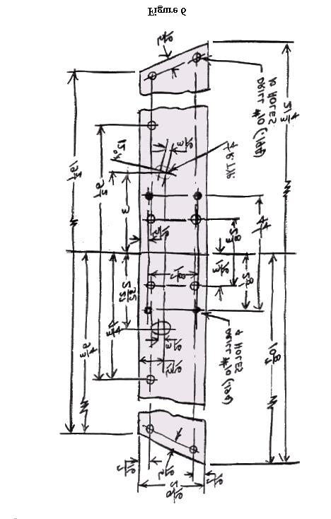
1 SERVICE BULLETIN REPUBLIC AVIATION CORPORATION FARMINGDALE, LONG ISLAND, NEW YORK SERVICE DEPARTMENT June 16, 1947 OPTIONAL CHANGE SERVICE BULLETIN NO. 17 INSTALLATION STEERABLE TAIL WHEEL (Includes Supplement 1 and Supplement 2) Reason for Change: Airplanes affected: To provide greater ease of taxiing under crosswind conditions. Republic Serial Nos. 5 through 875. Serial Nos. 876 and up have already had this change accomplished in production. Description of Change: This change involves the following steps: A. Tail Wheel Disassembly. B. Yoke Rework. C. Collar Rework. D. Fork Rework. E. Tail Wheel Assembly. F. Tail wheel Installation. G. Bulkhead Pulley Bracket Installation. H. Standpipe Installation. I. Rigging. NOTE: On Seabee Serial Nos. 5 through 125, which have the old type steel welded yoke and/or the old type shock absorber with the welded or machined type aft collar (new type collar is a forging with Part No. 17F stamped on the face of the left ear), it will be necessary to replace these either with Yoke Assembly Steerable Tail wheel Part No and/or Shock Absorber Steerable Tail Wheel Part No These parts will be required in addition to the conversion kit. 1 of 22
2 A. DISASSEMBLY TAIL WHEEL 1. Place cradle under tail wheel bulkhead so that tail wheel is raises off the ground. 2. Remove tail wheel fork and yoke assemblies by removing the bolt holding the yoke to the aft shock absorber collar and the bolt holding the yoke to the piston of the shock absorber. Cut the tail wheel lock cable at any convenient point. 3. Disassemble the yoke and fork assembly. Discard the spindle and hardware. Remove the lock pin and spring from the yoke assembly. 4. It is recommended that the complete tail wheel lock cable and handle in the cockpit be removed. B. YOKE REWORK 1. Rework the yoke assembly in accordance with Figure 1. It will be noted that this rework consists of removing the top portion of the yoke, which was previously used to support the lock pin aft pulley. It is suggested that this material be removed with a hacksaw and then file smooth to existing flat counterbore. Be sure to cover needle bearings to prevent chips, etc. from getting on them. 2. Place Cam Assembly 17F on top of yoke so that center of holes in cam and yoke line up within inches. Using pilot holes in cam as guides drill five holes #26 (.147) ¾ inch deep into yoke enlarging pilot holes in cam at same time. Tap holes in yoke and cam # /8 inch deep (NC-2). Countersink holes on top of cam.372 inch diameter by 82. Attach cam to yoke using five AN505C10-8 screws. Stake these screws in place. The top surface of the cam plate must be smooth after staking the screws. Refer to Figure 1. C. COLLAR REWORK 1. Rework aft shock absorber collar in accordance with Figure 2. This work can be accomplished with collar in place. This rework consists of removing the inboard ear on the collar. This ear may be removed with a hacksaw and filing smooth. Also note that a #22 (.157) 5/8 inch deep hole must be drilled and tapped # /2 inch deep (NF-3) into side of collar. 2. Place Wedge 17F on outboard side of ear on collar as shown in Figure 2 so that centers of pilot hole in wedge and hole in ear line up. Using full size #12 (.189) hole in wedge as guide drill #12 (.189) through ear on collar. Countersink 2 of 22
3 hole on inboard side of ear 82 by 1/32 inch deep as shown. Attach wedge to ear with 17F pin, staking pin on inboard side and filing smooth if necessary. Using pilot hole in wedge as guide drill and ream ¼ (.250) through wedge and ear normal (perpendicular) to outboard surface of wedge. D. FORK REWORK 1. Rework fork in accordance with Figure 3. Note that this rework consists of cutting two notches in top of fork. These notches are to be cut so that pin assembled in Spindle 17F just fits into them. It is recommended that these notches be made by drilling ¼ inch holes at dimension shown, opening hole with hacksaw and filing to proper width. 2. Assemble fork on spindle using two NAS washers, AN nut and AN cotter pin as shown on Figure 4. This nut must be torqued as tightly as possible (3000 in. lbs. Minimum). Do not back off to obtain cotter pin hole alignment. E. TAIL WHEEL ASSEMBLY 1. Referring to Figure 5 assemble yoke and quadrant assemblies on Fork and Spindle assemblies as follows: a. Place 17F washer over spindle. b. Place yoke assembly over spindle. c. Place Quadrant Assembly 17F with Bushing Assembly 17F over spindle. d. Place Washer 17F over spindle. e. Place two Spring Washers 17F over spindle. f. Fasten assembly together with two AN960-C1016 washers, one AN nut and AN380-C4-4 cotter pin tightening nut sufficiently to resist a 20# to 25# side load applied at the bottom of the fork. g. Apply AN-G-15 or equivalent waterproof grease at lubricating fittings on yoke. h. Assembly old wheel, tire, etc. on this assembly. 3 of 22
4 F. TAIL WHEEL INSTALLATION 1. Reassemble Yoke and Fork Assembly onto the aft collar and piston of the shock absorber as follows referring to Figure 10. a. Pass Bolt 17F through ears on collar and yoke from right side. b. ON left side place Bearing 17F over Bolt and Bracket Assembly 17F over bearing. c. Fasten bolt with AN320-6 nut and AN cotter pin. d. Fasten yoke to piston of shock absorber with original hardware. NOTE: Be sure bolts through both ends of shock absorber piston run horizontal to ground. G. BULKHEAD PULLEY BRACKET INSTALLATION 1. Make up drilling template to use for installing pulley bracket at Station as shown in Figure 6. This template may be used to drill holes through bulkhead due to lack of visibility. Use a piece of 21-3/4 x 2-9/16 x 1/8 Aluminum for this. If a large number of ships are to be reworked with the same template, it is recommended that steel be used. While making template check it against the bracket, pulley and cable assembly for alignment for holes. 2. Open hand holes in tail boom to obtain access to bulkhead Station This is the bulkhead directly above the aft end of the tail wheel lock. This bracket is on aft side of bulkhead. 3. Disconnect rudder and water rudder control cables at rudder cross tubes in cabin. Then remove bolts holding cables to link at point shown on Figure 8. Pass aft cables through bulkhead Station This will necessitate removal of the fairlead at this point. 4. Place drilling template in place on aft side of bulkhead Station referring to Figure 7 holding it in place with four bolts at existing fairlead holes and drill ten #10 (.194) holes through diameter holes through bulkhead using elongated holes in template as guides. Use a rotary or rat-tail file to open these holes up to full elongated size. Remove template. 5. Place Pulley Bracket complete with pulleys and cables in place against aft side of bulkhead Station and after threading cables through holes attach channel of 4 of 22
5 bracket assembly to bulkhead with ten AN3-4A bolts, AN nuts and AN washers. 6. Clamp a left and right Link 17M on either side of original links as shown on Figure 8 and drill #12 (.189) holes through original links using holes in new link as guides. Fasten new links to old links with AN pin, AN washer and AN cotter pin. 7. Thread rudder and water rudder control cables through proper holes in bulkhead Station and replace fairleads previously removed using original hardware. It may be necessary to trim outside edges of these fairleads so that they will fit in place. Reconnect these cables at correct turnbuckles and check for 25# ±5# cable tension. 8. Reinstall reworked links as shown in Figure 8 using AN24-14 bolt, AN320-4 nut and AN washer and AN cotter pin for each link. Reconnect cables at crosstube in cabin. 9. Attach each forward end of new steerable tail wheel control cables to links using an AN155-16L barrel, AN165-16L eye terminal, AN23-10 bolt, AN320-3 nut and AN cotter pin. Refer to Figure 8. H. STANDPIPE INSTALLATION 1. Install Standpipe 17F and Plate 17F as follows referring to Figure 9: a. Place Plate 17F against flange of Standpipe 17F and check alignment of plate nuts on flange of standpipe with pilot holes in plate. Open up pilot holes in plate with a #10 (.194) drill being sure to compensate for any misalignment. b. Draw a line on the hull 2 inches aft of the aft surface of the tail wheel shock absorber bearing. c. Place plate so that inboard edge of hole in it is 9/16 inches to the right of the vertical centerline of the airplane. The long centerline of the elongated hole in the plate should be on the line drawn under (b) above. Scribe hole to be cut in hull using hole in plate as guide. Cut hole in hull. d. Using holes in plate as guide, drill fifteen (15) #10 (.194) holes through hull. 5 of 22
6 e. Install Channel 17F in place as shown picking up two existing bolts through bulkhead Station f. Install two Bumpers 17F as follows referring to Figure 11: (1) Position of bumpers on right side of tail boom is to be determined by tail wheel fork in retracted and full swivel position. Mark location of interference with fork on tail boom. (2) Place bumpers at points of interference and using holes in bumpers as guides drill four #19 (.166) holes for each bumper. NOTE: If bumper overlaps skin splice, locate bumpers so that no holes are drilled in skin splice. If necessary use only two attaching holes. (3) Install each bumper with four AN screws, AN nuts and AN960-8 washers. g. Install standpipe and plate using fifteen AN screws and AN washers first applying ample amount of UL (or equivalent) sealing compound between the plate and hull. h. Attach top of standpipe to channel so that edges of standpipe match edges of aft leg of channels using an AN23-8A bolt, AN nut and AN washer. Use a #10 (.194) drill through top of standpipe for this bolt. i. Pass aft ends of steerable tail wheel control cables and pulleys as follows referring to Figure 10: I. RIGGING 1. Assemble steerable tail wheel control cables and pulleys as follows referring to Figure 10: a. Pass right hand control cable around an AN210-3A pulley. b. Assemble pulley to Bracket 17F with an AN24-22 bolt. c. Fasten pulley and bracket assembly to ear on aft shock absorber collar with Wedge 17F and an AN320-4 nut and AN380C2-2 pin. d. Pass left hand control cable around Pulley 17F and assemble this on collar with Bracket 17F , AN3H6 bolt and AN936-B10. 6 of 22
7 Parts Required: e. Pass left hand control cable around an AN210-3A pulley and fasten this pulley to bracket installed under paragraph F, 1b. with an AN24-14 bolt, AN320-4 nut and AN380C2-2 cotter pin. f. Attach right and left hand cables to right and left hand ears on quadrant with AN24-11 bolt, AN320-4 nut and AN380C2-2 cotter pin. Set cables for 8 lbs. Tension. Lockwire all turnbuckles. 2. Check hydraulic operation of tail wheel. 3. Check operation and travel of rudder and water rudder. 4. Remove hull cradle. 5. Place Decal 17F on instrument panel. Parts may be obtained through your local distributor or dealer. Service Bulletin Kit No. 17 consists of the following: Quantity Part Number Part Name * 1 17F Channel * 1 17F Bracket * 1 17F Bracket * 1 17F Bracket * 1 17F Bracket 1 17F Standpipe Weld Assy. 1 17F Plate 2 17F Washer **1 17F Quadrant Assy. 1 17F Washer 1 17F Pulley **1 17F Bushing ***1 17F Spindle 1 17F Cam Assembly 1 17F Washer ***1 17F Pin 2 17F Bumpers 1 17F Bolt 1 17F Bearing 1 17F Bracket 7 of 22
8 Quantity Part Number Part Name 1 17F Bracket Assy. 1 17F Bracket 1 17F Wedge 1 17F Wedge 1 17F Pin * 1 17F Cable Assy. * 1 17F Cable Assy. 2L/2R 17F Link 1 17F Channel 1 17F Decalcomania 1 AN3H6 Bolt 10 AN3-4A Bolt 1 AN23-8A Bolt 2 AN23-10 Bolt 2 AN24-11 Bolt 3 AN24-14 Bolt * 2 AN24-15 Bolt 1 AN24-22 Bolt 2 AN155-16L Barrell 2 AN165-16L Eye Terminal * 2 AN210-3A Pulley 2 AN210-3A Pulley 1 AN Nut 2 AN320-3 Nut * 2 AN320-4 Nut 6 AN320-4 Nut 1 AN320-6 Nut 8 AN Nut 11 AN Nut * 6 AN Cotter Pin 6 AN Cotter Pin 1 AN Cotter Pin 4 AN380C2-2 Cotter Pin 1 AN380C4-4 Cotter Pin 1 AN Cotter Pin * 4 AN Pin 2 AN Pin 5 AN505C10-8 Screw 15 AN Screw 8 AN Screw 1 AN936-B10 Washer 8 of 22
9 8 AN960-8 Washer 28 AN Washer * 2 AN Washer 2 AN Washer Quantity Part Number Part Name 2 AN Washer 1 AN Nut 2 NAS Washer * These parts make up the bracket, pulley and cable assembly. ** Quadrant and Bushing are delivered assembled. *** Spindle and Pin are delivered assembled. Tools Required: Mechanics standard handtools plus the following: Right Angle or Gooseneck Drill #26 (.147) Drill #22 (.157) Drill #19 (.166) Drill #12 (.189) Drill #10 (.194) Drill 1/4 (.250) Drill #10-24 NC-2 Tap #10-32 NF-3 Tap 82º.372 inch Diameter Countersink Time Required: Approximately 16 man-hours are required for modifying existing parts and 32 man-hours for installation of kit. Weight and Balance: Weight Arm Moment Non-Steerable T.W. Total Weight Steerable T.W. Total Weight Additional Ballast Necessary Make suitable entry in log book. W. H. Ehmann Service Manager 9 of 22
10 10 of 22
11 11 of 22
12 12 of 22
13 13 of 22
14 14 of 22
15 15 of 22
16 16 of 22
17 17 of 22
18 18 of 22
19 19 of 22
20 Supplement No. 1, Service Bulletin no. 17 July 1, 1947 Installation Steerable Tail Wheel To prevent steerable tail wheel control cable terminals from swiveling one hundred and eighty degrees on the quadrant when the tail wheel is retracted, rivets are placed along side the terminals. If the cable terminals swivel there is danger of breaking the cables. Some of the early quadrants shipped in kits did not have these rivets installed. Please inspect these quadrants and if the rivets are not evident, install a rivet, screw or bolt so that there is 3/32-inch clearance between the inboard edge of the terminal and edge of the head of the rivet, screw or bolt. 20 of 22
21 SUPPLEMENT NO. 2 Service Bulletin No. 17 October 16, 1947 INSTALLATION STEERABLE TAIL WHEEL It was recently brought to our attention that in instances where the Steerable Tail Wheel cable tension was not, at all times, rigorously maintained at specified limits the danger of resultant slack in these cables causing fouling was existent. In order to offset any possibility of this fouling, the following modification should be incorporated in the installation at the earliest possible date and not later than the next 25-hour inspection. 1. Make an overlay of the sketch of the horn (Figure 1) as shown on the reverse side of this supplement. 2. Use the overlay as a pattern to fabricate 2 pieces of this detail from.091 gauge aluminum plate. 3. Remove the quadrant arms from the tail wheel quadrant assembly after disconnecting the cable clips from the quadrant arms. 4. Drill out the stop-rivet from the arms. 5. Fit the horns to the arms as shown in Figure 1. Clamp into place. Drill out corresponding holes for attachment in the horn, using the arms as a template. (a) Drill F (.257) for clip attachment. (b) Drill #30 (.187) for rivet hole. 6. Rivet the horns to arms using an AN rivet. 7. Remove clamps and reassemble arms to the quadrant. 8. Spread the cable clips to fit over the horn and arm and attach with AN24-11 bolts. 9. Make suitable notation of compliance in the Aircraft Log. 21 of 22
22 22 of 22
Ayres service bulletin Corporation
 Ayres service bulletin Corporation No. SB-AG-37 P.O. BOX 3090 ONE AYRES WAY ALBANY, GEORGIA 31706-3090 PHONE 229/883-1440 FAX 229/439-9790 Service Bulletin No. SB-AG-37 Page 1 of 12 Approval: FAA Approved
Page: REV 3: Add drill and tap information to Figure 4 DRILL #3, TAP 1/4-28 BOTH ENDS.
 REVISION DESCRIPTION: 1) Page: 32-03 MEMO: Step 4 should not be bold. Fix WD-1213 callout in Figure 3. Page: 32-04 REV 3: Add drill and tap information to Figure 4 DRILL #3, TAP 1/4-28 BOTH ENDS. Add make
SERVICE KIT thru , 631, 634, 675 R thru R F thru F FR thru FR
 TITLE SEAT BELT AND SHOULDER HARNESS KIT INSTALLATION EFFECTIVITY MODEL SERIES SERIAL NUMBERS 182 33000 thru 18268368 182 613, 631, 634, 675 R182 R18200001 thru R18201973 F182 F18200001 thru F18200169
Section 13. Tail Rotor Drive. RotorWay International A600 TALON Construction Manual. Section 13. Page A
 RotorWay International Page A Tail Rotor Drive Procedures covered in this section: Install driveshafts and gearboxes; install drive belt and tensioner; fabricate and install tail rotor pitch actuator arms;
Airworthiness Directive Schedule
 Airworthiness Directive Schedule Aeroplanes Cessna 120 26 November 2015 Notes 1. This AD schedule is applicable to Cessna 120 aircraft manufactured under Federal Aviation Administration (FAA) Type Certificate
12.0 CONTROLS 3/3/2006. Page 1
 Page 1 Page 2 SR3500 Rudder Pedal Parts List ITEM DESCRIPTION PART NUMBER QTY 1 MASTER BRAKE PEDAL RP0015 2 2 SLAVE BRAKE PEDAL RP0016 2 3 PUSH ROD RP0017 4 4 SLAVE BRAKE TORQUE TUBE RP0018 2 5 MASTER
Seabee Annual Inspection Procedures
 Procedures Due to the wide variety of Seabee s flying out there, these procedures should be modified to fit YOUR Seabee. Make sure that all AD s are complied with as well as any required Service Bulletins
TEMPORARY REVISION NUMBER
 TEMPORARY REVISION NUMBER 7 DATED 1 DECEMBER 2011 MANUAL TITLE MANUAL NUMBER - PAPER COPY TEMPORARY REVISION NUMBER FR172 Reims Rocket 1968 Thru 1976 Service Manual D849-5-13 D849-5TR7 MANUAL DATE 15 August
TEMPORARY REVISION NUMBER
 TEMPORARY REVISION NUMBER 8 DATED 1 DECEMBER 2011 MANUAL TITLE MANUAL NUMBER - PAPER COPY TEMPORARY REVISION NUMBER 1978 Thru 1986 Model R182 & TR182 Service Manual D2069-3-13 D2069-3TR8 MANUAL DATE 15
ROLL BAR FRAME 2 PLACES F-1231A-FL ROLL BAR FRAME F-1231C INBOARD F-1231B OUTBOARD ROLL BAR STRAP BAGGAGE BULKHEAD
 SECTION 24iS/U: ROLLOVER F-1231A-FR ROLL BAR FRAME VAN'S AIRCRAFT, INC. F-1231A-AR ROLL BAR FRAME STRUCTURE F-1231E ROLL BAR SPLICE PLATE 2 PLACES F-1232A ROLL BAR BRACE F-01254-R-1 SUPPORT FRAME & F-01207
FUSELAGE ASSEMBLY SECOND SECTION (of three)
") FUSELAGE ASSEMBLY SECOND SECTION (of three) 1 FRONT FLOOR ASSEMBLY The front floor assembly is fabricated from three pieces of the two ply pre-pregnated panel material supplied. The basic floor panel and
FUSELAGE ASSEMBLY SECOND SECTION (of three) 1 FRONT FLOOR ASSEMBLY The front floor assembly is fabricated from three pieces of the two ply pre-pregnated panel material supplied. The basic floor panel and
Nomad RUDDER CONTROL SYSTEM STRENGTHENING OF CABLE PULLEY MOUNTING AT STA (MOD N630)
") RUDDER CONTROL SYSTEM STRENGTHENING OF CABLE PULLEY MOUNTING AT STA 74.52 (MOD N630) 1. PLANNING INFORMATION A. Effectivity (1) Aircraft Affected All N22 Series and N24 Series aircraft whose log books
RUDDER CONTROL SYSTEM STRENGTHENING OF CABLE PULLEY MOUNTING AT STA 74.52 (MOD N630) 1. PLANNING INFORMATION A. Effectivity (1) Aircraft Affected All N22 Series and N24 Series aircraft whose log books
Service Bulletin. ATA 27-00: Flight Controls Rudder-Aileron Interconnect Modification
 Service Bulletin Issued: 09 May 2007 Models SR20 and SR22 ATA 27-00: Flight Controls Rudder-Aileron Interconnect Modification COMPLIANCE Mandatory: Accomplish this Service Bulletin within 25 Flight Hours
Glasair Sportsman T3 Tailwheel Suspension System P/N: ABI-51526
 for P/N: Manufactured by ABI, LLC Doc No.: -II REV A October 4, 2018 Table of Contents 1 Introduction 1.1 Purpose 2 Kit Components 3 Applicability 4 Equipment Description 5 5.1 Remove Existing Equipment
D'Shannon Aviation PANEL INSTALLATION INSTRUCTIONS
 D'Shannon Aviation PANEL INSTALLATION INSTRUCTIONS Disconnect the battery posts 1. Windshield Removal NOTE: If the aircraft is equipped with a D'Shannon speed sloped windshield, you will not have to do
1. SUBJECT: F-28A and 280 Left Side Tail Rotor Installation
 Page 1 of 16 DATE: January 31, 2005 1. SUBJECT: F-28A and 280 Left Side Tail Rotor Installation 2. MODEL: F-28A and 280 3. EFFECTIVITY: All serial numbers 4. BACKGROUND: The left side installation of the
Seabee Annual/100-Hour Inspection
 Date Completed Seabee Annual/100-Hour Inspection ENGINE Mechanic s Initials 1 Drain engine oil and check for foreign material 2 Check oil screen for proper rotation or looseness 3 Safety Oil Plug 4 Refill
FUSELAGE CABIN ASSEMBLY
 SECTION 3 Cabin Frame Ref Dwg 8FC-3 The Top of the Cabin Frame is level The distance between the front and rear wing attachment to fit the wings SECTION 3 - Page 1 of 10 CABIN FRAME 8F18-1 The TOP TUBES
PARAVION TECHNOLOGY, INC AIRWAY AVENUE FT. COLLINS, COLORADO 80524
 PARAVION TECHNOLOGY, INC. 2001 AIRWAY AVENUE FT. COLLINS, COLORADO 80524 REPORT NO. INSTALLATION INSTRUCTIONS FOR 407PX-100 PEDAL EXTENSION INSTALLATION Page i Rev. F, 01/28/08 REVISIONS REV. DATE DESCRIPTION
Service Bulletin. SB-GA Issue 1. Subject: Horizontal Stabiliser Attachment Area Inspection and Reinforcement. Applicability: Amendments:
 PO Box 881, Morwell, Victoria 3840, Australia Ph + 61 (0) 3 5172 1200 Fax + 61 (0) 3 5172 1201 www.mahindraaerospace.com Service Bulletin SB-GA8-2016-163 Issue 1 OPTIONAL Subject: Horizontal Stabiliser
Section 75-ZA-3 Fin & Rudder Cable Fairing Installation
 Section 75-ZA-3 Fin & Rudder Cable Fairing Installation This manual has been prepared for installation of the Fin and Fairings. This photo assembly manual is intended as a supplement to the drawings. If
10. Lower Fuselage Assembly Undercarriage
 10. Lower Fuselage Assembly Undercarriage Undercarriage 10.27 2 230399 0 Jabiru Undercarriage Configurations There are four combinations of tyres available, utilising two sets of hubs (standard and heavy
REVISION DESCRIPTION:
 14401 Keil Road NE, Aurora, Oregon, USA 97002 PHONE 503-678-6545 FAX 503-678-6560 www.vansaircraft.com info@vansaircraft.com Service Letters and Bulletins: www.vansaircraft.com/public/service.htm REVISION
TEMPORARY REVISION NUMBER
 TEMPORARY REVISION NUMBER 7 DATED 1 DECEMBER 2011 MANUAL TITLE MANUAL NUMBER - PAPER COPY TEMPORARY REVISION NUMBER Model 188 & T188 Series 1966 Thru 1984 Service Manual D2054-1-13 D2054-1TR7 MANUAL DATE
BULLETIN. SERVICE No. 966 PIPER CONSIDERS COMPLIANCE MANDATORY Piper Drive Vero Beach, Florida, U.S.A
 Piper Aircraft Corporation 2926 Piper Drive Vero Beach, Florida, U.S.A. 32960 SERVICE No. 966 BULLETIN PIPER CONSIDERS COMPLIANCE MANDATORY January 21, 199 This Service Bulletin is divided into TWO (2)
INTRODUCTION. This Catalog:
 Editor s Note: This Parts Catalog has been reproduced from the original Republic Parts Catalog. Obviously, most of the information is obsolete; the pictures are accurate and up-to-date. If nothing else,
Diamond ALERT SERVICE BULLETIN AIRCRAFT
 Title: Throttle Cables, Replacement Page: 1 of 7 1. ATA Code: 7610 2. Effectivity: DA 20 Katana Aircraft S/N 10002 through 10300. 3. General: This service bulletin supersedes S.B. #DA20-76-01A Rev 4. A
SERVICE BULLETIN THIS BULLETIN IS FAA APPROVED FOR ENGINEERING DESIGN
 MOONEY INTERNATIONAL CORPORATION SERVICE BULLETIN 165 Al Mooney Road North Kerrville, Texas 78028 THIS BULLETIN IS FAA APPROVED FOR ENGINEERING DESIGN SERVICE BULLETIN M20-318 Date: June 2, 2014 SUBJECT:
AEROPRAKT SERVICE BULLETIN. No. SB A22LS-17 REPLACEMENT OF RUDDER CONTROL SYSTEM CABLES AND FAIRLEADS OF A-22, A-22L, A-22L2 AND A-22LS AIRCRAFT
 Aeroprakt Ltd AEROPRAKT SERVICE BULLETIN No. SB A22LS-17 REPLACEMENT OF RUDDER CONTROL SYSTEM CABLES AND FAIRLEADS OF A-22, A-22L, A-22L2 AND A-22LS AIRCRAFT Repeating symbols: Please, pay attention to
1970 Trans-Am Mustang Front Suspension Instructions. Manual, Volume One, Chassis. Special instructions and precautions will be given
 1970 Trans-Am Mustang Front Suspension Instructions 1. This kit was designed to be used in conjunction with the Rear Suspension kit. 2. This conversion follows standard procedures as described in the 1970
EFFECTIVITY Serial Numbers thru , 698
 Conquest TITLE AILERON HINGE BRACKET REPLACEMENT EFFECTIVITY Model Serial Numbers 441 441-0001 thru 441-0349, 698 DESCRIPTION To install stainless-steel aileron hinge brackets as a replacement for aluminum
Nomad FLIGHT CONTROLS -FITMENT OF MASS BALANCE TO RUDDER TAB
 FLIGHT CONTROLS -FITMENT OF MASS BALANCE TO RUDDER TAB. PLANNING INFORMATION A. Effectivity NOTE This revision carries additional information to facilitate incorporation of the modification, and includes
MODIFICATION KIT. Serial Numbers 300 (LC40-550FG) thru (LC42-550FG) thru (LC41-550FG) thru
 thru (LC42-550FG) thru (LC41-550FG) thru") Single Engine MODIFICATION KIT MK400-71-01 TITLE ENGINE OIL COOLER WINTERIZATION MODIFICATION EFFECTIVITY Model Serial Numbers 300 (LC40-550FG) 40004 thru 40079 350 (LC42-550FG) 42001 thru 421018 400 (LC41-550FG)
Single Engine MODIFICATION KIT MK400-71-01 TITLE ENGINE OIL COOLER WINTERIZATION MODIFICATION EFFECTIVITY Model Serial Numbers 300 (LC40-550FG) 40004 thru 40079 350 (LC42-550FG) 42001 thru 421018 400 (LC41-550FG)
SERVICE INFORMATION LETTER
 SERVICE INFORMATION LETTER DATE: August 19, 2015 SERVICE INFORMATION LETTER NO. 0183 Page 1 of 18 1. SUBJECT: Collective Stick Socket Replacement 2. MODEL: F28A, 280, F28C, 280C, F28F, 280F, and 280FX
Service Bulletin No.: DAC Date Issued: February 18, 2000 Title: Starting Vibrator Battery Installation Page: 1 of 6
 Title: Starting Vibrator Battery Installation Page: 1 of 6 1. ATA Code: 7410 2. Effectivity: DA20-C1 s/n C0001 up to and including C0102. 3. General: This service bulletin addresses the installation of
2. MODEL: F-28A, F-28C, F-28F, 280, 280C, 280F, and 280FX
 Page 1 of 6 DATE: September 5, 2002 1. SUBJECT: Idler Pulley Actuator Arm Inspection 2. MODEL: F-28A, F-28C, F-28F, 280, 280C, 280F, and 280FX 3. EFFECTIVITY: All Serial Numbers 4. BACKGROUND: Enstrom
ZODIAC 601 XL. Trim the outboard corner of the front flange of the center spar 6W4-1. Corner should not touch the side of the cabin floor skin 6B10-1.
 Trim the outboard corner of the front flange of the center spar 6W4-1. Corner should not touch the side of the cabin floor skin 6B10-1. Tape the side skins to the cabin floor skin (area in front of the
INSTALLATION INSTRUCTIONS EXTERNAL AUXILIARY FUEL SYSTEM P/N
 INSTALLATION INSTRUCTIONS EXTERNAL AUXILIARY FUEL SYSTEM P/N 41228-000-002-007 Page 1 of 45 List of Revisions Rev. Date Pages Description Approved IR 09/12/05 All Initial Release N/C All Updated to Apical
Page REV 1: Added "Step 4: Bend the tabs on the wiring channel to match the slant of the F L & -R Tunnel Sides."
 14401 Keil Road NE, Aurora, Oregon, USA 97002 PHONE 503-678-6545 FAX 503-678-6560 www.vansaircraft.com info@vansaircraft.com Service Letters and Bulletins: www.vansaircraft.com/public/service.htm REVISION
The engine cowling installation and firewall should be inspected and modified as specified in this Service Bulletin.
 Single Engine Service Bulletin August 25, 2008 TITLE ENGINE COWLING ALIGNMENT INSPECTION AND MODIFICATION EFFECTIVITY Model Serial Numbers 172R 17280001 thru 17280724 172S 172S8001 thru 172S8201 REASON
1. SUBJECT: Replacement of the Low Point Drain Valve. 3. EFFECTIVITY: TH-28; Serial Number 3004 and 3006
 Page 1 of 6 DATE: October 6, 2000 1. SUBJECT: Replacement of the Low Point Drain Valve 2. MODEL: TH-28 and 480 3. EFFECTIVITY: TH-28; Serial Number 3004 and 3006 4. BACKGROUND: 480; Serial Numbers 5001
Single Engine. Service Bulletin TITLE ELEVATOR TRIM TAB ACTUATOR ASSEMBLY INSPECTION EFFECTIVITY. Group A airplanes: Serial Numbers
 Single Engine Service Bulletin March 12, 2007 TITLE ELEVATOR TRIM TAB ACTUATOR ASSEMBLY INSPECTION EFFECTIVITY Group A airplanes: Model Serial Numbers 172R 17281353 thru 17281364, 17281369 thru 17281372
FIGURE 2: ADDING FITTINGS TO BRAKE ASSEMBLY (RIGHT SHOWN) FIGURE 1: ATTACHING AND ALIGNING THE MAIN GEAR AXLES
 FIGURE 1: ATTACHING AND ALIGNING THE MAIN GEAR AXLES") VAN'S AIRCRAFT, INC. Step 2: Apply pipe thread sealant and attach the fluid fittings to the brake as shown in Figure 2. Note that the brakes should mirror each other when installed. Step 1: Bolt the main
VAN'S AIRCRAFT, INC. Step 2: Apply pipe thread sealant and attach the fluid fittings to the brake as shown in Figure 2. Note that the brakes should mirror each other when installed. Step 1: Bolt the main
DESCRIPTION This service document provides instructions to inspect the Pre-2014 LH yokes.
 PRE-2014 LH3600-5 YOKE SERVICE BULLETIN Date: 8 March 2018 REASON: Airglas has received 4 reports of the LH4000 yoke (PN LH3600-5) of the welds shearing off the outboard arm of the yoke. The common thread
RIGGING THE FLIGHT CONTROLS
 RIGGING THE FLIGHT CONTROLS Rigging refers to the installation and adjustment of the rods that move flight surfaces in response to inputs from the controls of the helicopter. These rods are cut to length,
SERVICE DIRECTIVE BULLETIN
 SERVICE DIRECTIVE BULLETIN SERVICE DIRECTIVE BULLETIN NO. 0127 Page 1 of 6 DATE: June 20, 2018 1. SUBJECT: Rod End Inspection 2. MODEL: F-28, F-28A, F-28C, F-28C-2, F-28C-2R, F-28F, F-28F-R, 280, 280C,
Page REV 1: Added 'Step 2: See the "REMOVE THIS TAB, BOTH SIDES" callout near Detail A. Modify four SB375-4 Snap Bushings as shown.
 14401 Keil Road NE, Aurora, Oregon, USA 97002 PHONE 503-678-6545 FAX 503-678-6560 www.vansaircraft.com info@vansaircraft.com Service Letters and Bulletins: www.vansaircraft.com/public/service.htm REVISION
Mooney Mite M-18X Plans and Drawings Index Arranged by Group Miscellaneous Group
 Miscellaneous Group 110470 Bushings - Special 314410 Airspeed & Altimeter Installation 110190 Arm - Landing Warning 110070 Button - Static Airspeed 213260 Cone - Wing Fillet 110120 Control - Placard 616100
GlaStar and Sportsman Service Bulletin 67
 GlaStar and Subject: Applicability: Issue: Compliance Time: Elevator counterweights All GlaStar and Aircraft Counterweight attachment to elevator end rib At or before next condition inspection Discussion
REVISION DESCRIPTION:
 REVISION DESCRIPTION: 1) Page: 12-03 REV 1: Step 1: and Figure 1: Final-Drill s.b. Match-Drill. Step 4: Updated flox mixture description to match later description (removed "peanut butter-like" description).
N398CM. RC-3 Serial Number 387 Zero Timed Restoration Details
 RC-3 Serial Number 387 Zero Timed Restoration Details WING GROUP: Complete disassembly of wings, flaps, ailerons, lift struts, floats, and float struts. removal, alodine dip, and epoxy prime, w/bms 10-11.
FLAP, AILERON, FLAP/FUSELAGE AND STABILATOR GAP SEAL INSTALLATION AND MAINTENANCE MANUAL
 FLAP, AILERON, FLAP/FUSELAGE AND STABILATOR GAP SEAL INSTALLATION AND MAINTENANCE MANUAL Aircraft Eligibility: Piper PA-28-151, PA-28-161, PA-28-181, PA-28-201T, PA-28-236, PA- 28R-201, PA-28R-201T, PA-28RT-201,
Pitch Control and Trim
 Pitch Control and Trim GENERAL 27-30: PITCH CONTROL AND TRIM. General This section describes that portion of the flight control system which controls the position and movement of the elevator. This includes
Installation Instructions
 Preparing your vehicle to install your brake system upgrade 1. Rack the vehicle. 2. If you don t have a rack, then you must take extra safety precautions. 3. Choose a firmly packed and level ground to
FAA approval has been obtained on technical data in this publication that affects airplane type design.
 Single Engine Service Bulletin January 28, 2008 TITLE ENGINE COWLING ALIGNMENT INSPECTION AND MODIFICATION EFFECTIVITY Model Serial Numbers 172R 17280725 thru 17281262 172S 172S8202 thru 172S10006 REASON
Comanche Tail Problems and Cures
 Comanche Tail Problems and Cures As our Comanche fleet ages our maintenance requirements will continue to change. We re only one year away from Comanches having their 50 th birthday. The newest Comanche
CIRRUS AIRPLANE MAINTENANCE MANUAL
 MODEL SR0 YAW CONTROL AND TRIM. GENERAL This section describes that portion of the flight control system which controls the position and movement of the rudder. Included are; rudder system rigging, rudder
11 - Fairings. Fairings. February XLF Page 11-1
 11 - Fairings Fairings February 2003 11-XLF Page 11-1 11 - Fairings This Page Intentionally Left Blank Page 11-2 11-XLF February 2003 11 - Fairings Contents 11.0 - Chapter Preface... 11-4 11.0.1 - Parts
Yaw Control and Trim. 1. General. A. Yaw Control System. B. Yaw Trim System
 CIRRUS AIRPLANE MAINTENANCE MANUAL MODELS SR AND SRT Yaw Control and Trim CHAPTER 7-0: YAW CONTROL AND TRIM GENERAL 7-0: YAW CONTROL AND TRIM. General This section describes that portion of the flight
SERVICE BULLETIN THIS BULLETIN IS FAA APPROVED FOR ENGINEERING DESIGN
 SERVICE BULLETIN SERVICE BULLETIN M20-325 THIS BULLETIN IS FAA APPROVED FOR ENGINEERING DESIGN SUBJECT: Service Instruction M20-88A - STABILIZER TRIM STOP/SCREW MODIFICATION Dated 12/14/2016. MODELS/ SN
CIRRUS AIRPLANE MAINTENANCE MANUAL
 ELEVATOR AND PITCH TRIM SYSTEM 1. DESCRIPTION This section describes that portion of the flight control system which controls the position and movement of the elevator. Included are; elevator system torque
Section 75-FA-4. Forward Fuselage
 Section 75-FA-4 This manual has been prepared for assembly of the forward fuselage skins supplied with match drilled parts. This photo assembly manual is intended as a supplement to the drawings. If there
Eibach Pro-Damper Shocks & Struts (05-09 All):
:") Eibach Pro-Damper Shocks & Struts (05-09 All): Required tools: 3/8 and 1/2 drive ratchets 7, 8, 10, 15, 16, 17, 18, 21 & 22 mm open ended wrenches 8 & 10 mm box end wrenches 10mm socket 13, 15 & 18 mm
Eibach Pro-Damper Shocks & Struts (05-09 All): Required tools: 3/8 and 1/2 drive ratchets 7, 8, 10, 15, 16, 17, 18, 21 & 22 mm open ended wrenches 8 & 10 mm box end wrenches 10mm socket 13, 15 & 18 mm
INSTALLATION INSTRUCTIONS
 INSTALLATION INSTRUCTIONS INSTALLATION INSTRUCTIONS FOR A136 REAR DRUM TO DISC BRAKE CONVERSION KIT for 1970-75 Jeep, CJ SERIES with Dana 44 flanged axle Thank you for choosing STAINLESS STEEL BRAKES CORPORATION
P68 VARIANTS SERVICE INSTRUCTION. No. 89
 vulcanair spa via g. pascoli, 7 80026 casoria (na) italia Tel +39 081 5918111 Fax +39 081 5918172 info@vulcanair.com www.vulcanair.com P68 VARIANTS SERVICE INSTRUCTION No. 89 SUBJECT: MODIFICATION ON FRONT
Airglas, Inc. Installation Instructions. MANUAL NO. LH MODEL LH4000 Ski Kit For Cessna 180 and 185 Aircraft.
 Airglas, Inc. Installation Instructions MANUAL NO. LH4000-105 MODEL LH4000 Ski Kit For Cessna 180 and 185 Aircraft Cage Code 17564 This Page Intentionally Left Blank 2 P a g e REV LEVEL Initial Release
AVIAT AIRCRAFT INC. P.O. Box South Washington Afton, WY USA Fax:
 DATE: 7 February 2000 REVISION: Orig. AIRCRAFT: PITTS SPECIAL S-2C P.O. Box 1240 672 South Washington Afton, WY 83110 USA 307-886-3151 Fax: 307-885-9674 aviat@aviataircraft.com SUBJECT: Elevator Forward
"Figure 2: Trim Washer" was "Figure 1: Trim Washers". Page: 40A-06 REV 1: In Step 6, added "Fully torque the nut."
 14401 Keil Road NE, Aurora, Oregon, USA 97002 PHONE 503-678-6545 FAX 503-678-6560 www.vansaircraft.com info@vansaircraft.com Service Letters and Bulletins: www.vansaircraft.com/public/service.htm REVISION
SERVICE KIT. February 8, 1980 Revision C - April 16, 1999 Page 1 of 24
 , TITLE WING FRONT SPAR LOWER CAP MODIFICATION EFFECTIVITY MODEL YEAR SERIAL NUMBERS 401 1967/1968 401-0001 thru 401-0322 401A 1969 401A0001 thru 401A0132 401B 1970/1971 401B0001 thru 401B0121 401B 1972
Detroit Speed, Inc. Mini-Tub Kit Chevy Nova, Oldsmobile Omega, Pontiac Ventura P/N: &
 Detroit Speed, Inc. Mini-Tub Kit 1968-74 Chevy Nova, Oldsmobile Omega, Pontiac Ventura P/N: 041207 & 041208 Item Component Quantity 1 DSE Mini Tubs 1968-74 X-Body 2 2 Rear Upper Shock Crossmember 1 3 Upper
EVOLUTION OF THE MODEL A FORD FRAME ASSEMBLY A-5005-A, B, C AND D ACCORDING TO THE FORD ENGINEERING RELEASES STEVE C. PLUCKER COPYRIGHT, 2005
 1 EVOLUTION OF THE MODEL A FORD FRAME ASSEMBLY A-5005-A, B, C AND D ACCORDING TO THE FORD ENGINEERING RELEASES BY STEVE C. PLUCKER COPYRIGHT, 2005 AS OF: JANUARY 9, 2006 OCTOBER, 1927 A1------A137 OCTOBER
Installation Instructions
 Parts Installation Instructions DESCRIPTION PART # QTY A Alignment Tab PN ESB101 1 B Drill Guide PN ESB102 1 C Actuator Cable Assembly PN ESB103 1 C1 72 Actuator Cable 1 C2 5/16 Jam Nut 1 C3 Star Washer
Part # Mustang Complete CoilOver Kit
 Front Components: Part # 12100109 67-70 Mustang Complete CoilOver Kit 1 12103509 Non Adjustable Front CoilOvers 1 12102899 Lower StrongArms 1 12103699 Upper StrongArms Rear Components: 1 12106509 Non Adjustable
1. SUBJECT: Cyclic Trim System Cyclic Trim Assembly Kit for the Lateral and Longitudinal Trim Actuator Assemblies
 DATE: January 23, 2012 SERVICE DIRECTIVE BULLETIN NO. 0110 Page 1 of 9 1. SUBJECT: Cyclic Trim System Cyclic Trim Assembly Kit for the Lateral and Longitudinal Trim Actuator Assemblies 2. MODEL: All F-28F,
INSTALLATION INSTRUCTIONS
 INSTALLATION INSTRUCTIONS Hidden Winch Mount For 2008 Ford Super Duty Kit 78105 Your safety, and the safety of others, is very important. To help you make informed decisions about safety, we have provided
Module 6: Air Foundation Brakes
 Air Brakes Terms and Definitions Basic Components That Make Up Air Foundation Brakes Types of Air Foundation Brakes Parts of a Cam Foundation Brake Parts of a Wedge Foundation Brake Parts of a Disc Foundation
P68 VARIANTS SERVICE INSTRUCTION. No. 88
 vulcanair spa via g. pascoli, 7 80026 casoria (na) italia Tel +39 081 5918111 Fax +39 081 5918172 info@vulcanair.com www.vulcanair.com P68 VARIANTS SERVICE INSTRUCTION No. 88 SUBJECT: TYPICAL REPAIR OF
99-06 CHEVY/GM LIFT KIT
 92127200 99-06 CHEVY/GM 1500 6 LIFT KIT Thank you for choosing Rough Country for all of your suspension needs. Rough Country recommends a certified technician installs this system. In addition to these
1. SUBJECT: : New Improved Tail Rotor Teeter Bearing Assembly. 2. MODELS: F28C, 280C, F28F, 280F, 280FX, TH-28 and 480 Helicopters
 SERVICE INFORMATION LETTER NO. 0141 Page 1 of 5 DATE: September 11, 1995 1. SUBJECT: : New Improved Tail Rotor Teeter Bearing Assembly 2. MODELS: F28C, 280C, F28F, 280F, 280FX, TH-28 and 480 Helicopters
1) Page: REV 5: Changed depiction to show added hardware and T-01220
 Page: REV 5: Changed depiction to show added hardware and T-01220") REVISION DESCRIPTION: 1) Page: 37-01 REV 5: Changed depiction to show added hardware and T-01220 Page: 37-02 REV 4: Added Figure 3 depicting Separating the T-01220 Doublers. Figure 4 was Figure 3. Added
REVISION DESCRIPTION: 1) Page: 37-01 REV 5: Changed depiction to show added hardware and T-01220 Page: 37-02 REV 4: Added Figure 3 depicting Separating the T-01220 Doublers. Figure 4 was Figure 3. Added
600 SERIES STANDARD DUTY STRAIGHT TRACK INSTALLATION INSTRUCTIONS
 600 SERIES STANDARD DUTY STRAIGHT TRACK INSTALLATION INSTRUCTIONS PLEASE READ INSTRUCTIONS THOROUGHLY BEFORE BEGINNING. A. BI-PARTING TRAVEL 1. Before raising track into position, determine location of
PARAVION TECHNOLOGY, INC AIRWAY AVENUE FT. COLLINS, COLORADO 80524
 PARAVION TECHNOLOGY, INC. 2001 AIRWAY AVENUE FT. COLLINS, COLORADO 80524 REPORT NO. PR-369DA-900M PNEUMATIC DOOR OPENER INSTALLATION INSTRUCTIONS FOR 369PDO-100 369, 500N & 600N HELICOPTERS Page i REVISIONS
SERVICE BULLETIN REVISION TRANSMITTAL
 REVISION TRANSMITTAL This sheet transmits Revision 1 to, which: A. Adds HDWR kit to the MATERIAL INFORMATION section. NOTE: This revision replaces the original issue of in its entirety. REVISION COMPLIANCE
Installation Instructions
 Equipment Required: Installation Instructions Fastener Kit: F Wrenches: 8mm, 13mm, 3/4, 15/16 Drill Bits: 1/4 Other Tools: Drill, Reciprocating Saw, File WARNING: Under no circumstances do we recommend
2000 SERIES SPEEDBRAKE INSTALLATION MANUAL PA28/PA32 STC # SA00762SE
 INSTALLATION REPORT NO. 08067 Serial Number PRECISE FLIGHT, INC. 800-547-2558 2000 SERIES SPEEDBRAKE INSTALLATION MANUAL PA28/PA32 STC # SA00762SE NOTE: READ THESE DIRECTIONS BEFORE STARTING! CHECK FOR
DISC BRAKE/DUAL MASTER CYLINDER CONVERSION. Tools, Equipment and Supplies Needed:
 Please take the time to read the enclosed instructions carefully. If you have any questions, call our Product Assistance personnel for clarification. It is important to note that these instructions contain
SERVICE BULLETIN. Fuselage Tail Cone Damage
 Fuselage Tail Cone Damage It has come to our attention that a number of Sportsman tailwheel installations have resulted in crushed and/or delaminated fuselage laminates near the aft tailwheel bracket.
Kit No Please read these instructions completely before proceeding with installation. Air Spring Kit Parts List. Bracket Attaching Hardware
 Kit No. 59532 MN-572 (021108) ECR 7136 Please read these instructions completely before proceeding with installation Air Spring Kit Parts List A Item Description Quantity A Air Sleeves 2 B Upper Brackets
Please read these instructions completely before proceeding with the installation.
 Fits Multi-Leaf Steel Spring Models Only. P/N 59111 This kit is for a 2" drop Please read these instructions completely before proceeding with the installation. by MN-346 (03006) ECN3100 Nylon Nut Upper
VR482 Hay Rake OPERATOR & PARTS MANUAL. Last Updated: May 12, 2014
 VR482 Hay Rake OPERATOR & PARTS MANUAL Last Updated: May 12, 2014 Bridgeview Manufacturing Inc. P.O. Box 4 Gerald, SK S0A 1B0 (306) 745-2711 www.bridgeviewmanufacturing.com bmi@sasktel.net Your Authorized
80-96 Ford F150 / Bronco 4WD Class II 4"- 6" Suspension Lift Installation Instructions
 www.skyjacker.com Required Tool List: 80-96 Ford F150 / Bronco 4WD Class II 4"- 6" Suspension Lift Installation Instructions Safety Glasses Metric / Standard Wrenches & Sockets Floor Jack Jack Stands Measuring
ATTACHMENT. Orders for the required parts listed below must be placed by using this form only. Service Station/Company Code: Company Name:
 Single Engine ATTACHMENT CREW SEAT RECLINE MODIFICATION SB04-25-01 Revision 4 Orders for the required parts listed below must be placed by using this form only. NOTE: All web orders for these kits/parts
Model 912 / 922 AUGER HEADER and Model 722 HAY CONDITIONER Model 933 Grass Seed Special AUGER HEADER
 Model 912 / 922 AUGER HEADER and Model 722 HAY CONDITIONER Model 933 Grass Seed Special AUGER HEADER PARTS CATALOG Form 46619 Issue 01/06 Sugg. Retail: $15.00 Inside Front Cover (blank) Models 912, 922
CIRRUS AIRPLANE MAINTENANCE MANUAL
 MODEL SR PASSENGER AND CREW DOORS. DESCRIPTION AND OPERATION Serials 000 thru 00: The two crew/passenger doors incorporate a flush-mount outside door handle, key-operated door lock, and a conventional
Page: REV 1: In Step 4 "a minimum of 1/16 [1.6 mm] gap" was "an approximately 1/16 [1.6 mm] gap."
![Page: REV 1: In Step 4 a minimum of 1/16 [1.6 mm] gap was an approximately 1/16 [1.6 mm] gap.](/thumbs/72/66557156.jpg "Page: REV 1: In Step 4 a minimum of 1/16 [1.6 mm] gap was an approximately 1/16 [1.6 mm] gap.") 14401 Keil Road NE, Aurora, Oregon, USA 97002 PHONE 503-678-6545 FAX 503-678-6560 www.vansaircraft.com info@vansaircraft.com Service Letters and Bulletins: www.vansaircraft.com/public/service.htm REVISION
14401 Keil Road NE, Aurora, Oregon, USA 97002 PHONE 503-678-6545 FAX 503-678-6560 www.vansaircraft.com info@vansaircraft.com Service Letters and Bulletins: www.vansaircraft.com/public/service.htm REVISION
Single Engine MODIFICATION KIT
 Single Engine MODIFICATION KIT TITLE SECURITY LOCK INSTALLATION EFFECTIVITY Model Serial Numbers 172R 17280001 and On 172S 172S8001 and On 182S 18280001 thru 18280944 182T 18280945 and On T182T T18208001
OPTIONAL SERVICE BULLETIN OSB OSB 42NG-062
 DAI OSB 42-124 DAI OSB 42NG-062 Page 1 of 3 OPTIONAL SERVICE BULLETIN OSB 42-124 OSB 42NG-062 I TECHNICAL DETAILS I.1 Category Optional. I.2 Airplanes affected Type: Serial numbers: DA 42, DA 42 M, DA
SERVICE BULLETIN SB0017 Rev A Page 1 of 5
 SERVICE BULLETIN SB0017 Rev A Page 1 of 5 EFFECTIVE DATE: This Service Bulletin is effective November 15, 2016. SUBJECT: MODELS AFFECTED: COMPLIANCE TIME: PURPOSE: STABILIZER YOKE CC18-0002 THROUGH CC18-0083
JK REAR BUMPER AND TIRE CARRIER
 JK REAR BUMPER AND TIRE CARRIER Installation Guide AEV30105AA (Updated 5/10/10) Page 1 of 20 Page 2 of 20 EXPLODED VIEW PLEASE READ BEFORE YOU START IN ORDER TO INSTALL THIS PART PROPERLY YOU OR YOUR INSTALLER
Part # Chevy Level 2 Air Suspension Package One Piece Frame
 350 S. St. Charles St. Jasper, In. 47546 Ph. 812.482.2932 Fax 812.634.6632 www.ridetech.com Part # 11020299 55-57 Chevy Level 2 Air Suspension Package One Piece Frame Front Components: 1 11013001 Master