HV connectivity tests after Barrel connection
|
|
|
- Jonah Dickerson
- 5 years ago
- Views:
Transcription
1 TRT detector high voltage system ATLAS Project Document Institute Document No. Created: 07/09/2006 Page 1 of 11 Modified: REV.: 1.00 HV connectivity tests after Barrel connection Procedure Abstract TRT barrel. This document describes the tests performed after the initial HV harnesses connection to the Introduction HV Layout Test Procedures Chiho Wang Prepared by: Checked by: Jack Fowler Harold Ogren Seog Oh Anatoli Romaniouk Approved by:
2 Distribution List Page:2 of 11
3 Page: 3 of 11 History of Changes Rev. No. Date Pages Description of changes
4 Page: 4 of 11 Table of Contents Introduction HV Layout Test Procedures Appendix 1: HV Mapping from HV PS Channels to Straws
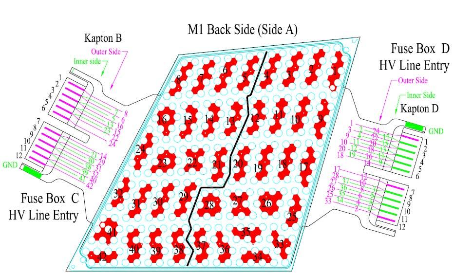
5 Page: 5 of 11 1 Introduction: This procedure covers the TRT barrel HV check after the HV connection is made. Testing of harnesses from USA15 to PPB1 is described in procedure and should have been performed before hand. This procedure extends the tests to the detector itself. All tests are performed remotely from USA15. Some repair and trouble shooting may require access to detector front. 2 HV Layout A brief description of the TRT barrel HV connections is available in procedure Detailed pin-out and mapping informations are available at TRT Barrel Twiki page From PPB1, a HV harness splits into individual HV coax cables and feed into 6 fuse boxes; 2 for each type of module. There are 22 HV coax for a stack of 3 modules: 6 for type 1, 6 for type 2 and 10 for type 3. Inside a fuse box, after a filter circuit, a HV line fans out to several fuses, ranging from 6 to 10 depending on module type and line position. Each fuse serves one trace on the module HV Kapton that feeds 8 straws. The HV ground in the fuse box are commoned after filter circuits and connected to the module tension plate through module HV kapton. A capacitor between tension plate and HV plate separates the high voltage on the straws from its ground. The tension plate ground is also electronics analog ground and is common to all barrel modules throught space frame. Individual grounds in HV coax are also commoned at USA15 on the face of HV PS crate. Some reference drawings and mapping information at the detector side are listed in Appendix Pre-condition Complete and final connection of HV harnesses to TRT barrel. 3 Test procedures After HV harnesses are connected to TRT barrel the followings are tested from USA15 for the barrel HV integrity: 1. A capacitance and resistance measurement to check HV connectiveity from HV PS to straws. 2. A HV test at 500V to check sense wire wellness. 3.1 Capacitance measurement Tools: 1. Capacitance meter 2. Lemo connector distribution box (Figure 1) 3. Excel spread sheet for data recording.
 2.")
6 Page: 6 of 11 Figure 1, Lemo distribution box Steps: 1. Disconnect lemo conectors from HV PS and connect to distribution box. The connector and the HV PS should have been clearly marked. If not they should be marked before continuing Do 1 stack of 8 connectors at a time. The 8 th connector is a mix from 3 stacks (Apendex 1) 2. Measure capacitance for each HV line with capacitance meter 3. Record in excel spread sheet. 4. Switch meter to resistance and check that resistance is infinity. 5. Compare measurement with data from procedure and previous measurement in SR Repair any broken wire, or fuse. Comments: The capacitance value measured should be (SR1 data) + (procedure 1.1.4) 1.6nF (type 2 cable capacitance) If capacitance is above normal possibility of connected HV islands. o Check passport for record of connected HV islands o Measure resistance between HV lines (should be infinity if no connection) If capacitance is below normal (by 1-2 nf) possibility of broken fuse. o Apply 50V and measure from dummy fuse box side to determine which fuse causes problem. o Open fuse box to check/repair fuses If capacitance is very low possibility of broken line or bad resistors in the fuse box. o Since all ground lines are commoned at the distribution box, and at the detector front. No line should show a broken ground symptom, e.g. < ~8 nf. At this stage it s most likely a broken HV line unless all ground lines from this stack are broken!
7 Page: 7 of HV test Tools: 1. HV PS crate and control software 2. Current readout and recording mechanism (excel spread sheet) Steps: 1. Check interlock for proper connection. 2. Raise HV to 500V for each stack 3. Record/observe current draw for 10 sec. 4. Diagose and repair any short circuit or excessive current draw Comment: Measure resistance from dummy side HV trace to ground to find out which HV island is shorted. The only way to find out which wire is broken is through electronics readout, or remove roof board!!
8 Page: 8 of 11 Appendix 1: HV Mapping from HVPS channels to Straw: The mapping table is available in excel format at TRT Barrel Wiki page: Naming convention in the table and the actual locations are explained in the following supporting figures. The HV PS side of mapping is explained in procedure apendix 1.

9 Page: 9 of 11


10 Page: 10 of 11


11 Page: 11 of 11
Fuse Box Layout. Duke Atlas Group
 Fuse Box Layout Dukhep-2004-12-13 Duke Atlas Group 1. Overview In the barrel TRT, high voltage is connected to the module through an external connector assembly called "fuse box" which includes filter
SECTION 12M - SUPPLEMENTAL RESTRAINT SYSTEM (VERSIONS 8.0 AND 8.1)
") SECTION 12M - SUPPLEMENTAL RESTRAINT SYSTEM (VERSIONS 8.0 AND 8.1) IMPORTANT Before performing any Service Operation or other procedure described in this Section, refer to Section 00 CAUTIONS AND NOTES
SECTION 12M - SUPPLEMENTAL RESTRAINT SYSTEM (VERSIONS 8.0 AND 8.1) IMPORTANT Before performing any Service Operation or other procedure described in this Section, refer to Section 00 CAUTIONS AND NOTES
Contents. Formula Student UK Appendix FSUK-C-2
 Contents 1. General... 3 1.1. Objective of the FSA Cost Rule Extension... 3 2. Materials parameterization clarification... 4 2.1. ECU, Rapid Prototyping... 4 2.2. ECU, Automotive... 4 2.3. ECU, Industrial...
Solar Inverter/Charger
 Solar Inverter/Charger PV1100 PLUS Table of Contents 1. General Information...1 1.1 Brief Introduction. 1 1.2 Inverter Schematic Diagram.1 1.3 Inverter Components Instructions... 2 2. Fault Code...3 3.
Feature Description. Version History
 TA2 Malfunction Indicator Lamp (MIL) and Engine Protection Document Number: FD-0007 Author: J. Goodloe Version: 03 Publish Date: 2016-03-18 Feature Description Version History Version Date Modified Sections
O2 Sensor Testing. If your engine has unexpectedly started to run poorly, an O2 Sensor Test should be performed.
 O2 Sensor Testing If your engine has unexpectedly started to run poorly, an O2 Sensor Test should be performed. IMPORTANT: Testing the O2 sensors using the procedures below REQUIRES that the engine will
Northwest RV Supply Manual Compliments of Printed From TROUBLESHOOTING
 TROUBLESHOOTING for the 5 BUTTON 3109228.001 COMFORT CONTROL CENTER SYSTEM INTRODUCTION The Comfort Control Center control system can be used to operate the following Duo-Therm Units: Roof Top Air Conditioners
620 Magnolia Avenue Suite B Ontario, CA (909) Diagnostic and Troubleshooting. Golf Cart. Revision: A Date:
 Diagnostic and Troubleshooting. Golf Cart. Revision: A Date:") 620 Magnolia Avenue Suite B Ontario, CA 91762 (909) 923-1973 Diagnostic and Troubleshooting Golf Cart Revision: A Date: 9-25-13 Diagnostics Diagnostics information can be obtained by observing the fault
620 Magnolia Avenue Suite B Ontario, CA 91762 (909) 923-1973 Diagnostic and Troubleshooting Golf Cart Revision: A Date: 9-25-13 Diagnostics Diagnostics information can be obtained by observing the fault
INSTALLATION INSTRUCTIONS AMBASSADOR DRUM OVERHEAD SERIES 100 DUMBWAITER
 INSTALLATION INSTRUCTIONS AMBASSADOR DRUM OVERHEAD SERIES 100 DUMBWAITER The installation of Matot Drum Dumbwaiters should only be performed by qualified, experienced, and trained elevator installers.
Battery Control Center - Diesel
 Service Manual CAUTION: All servicing of the Battery Control Center should be done only by a qualified Service Technician. Inadvertent shorts inside the Battery Control Center could result in severe damage
TECHNICAL DATA Troubleshooting Tips for DC to DC Converter
 When power supplies do not function properly, please check the following troubleshooting table before returning a unit. If the power supply still has a problem, please contact the designated distributors
Grounding Systems. Resistance. Resistance Grounding Systems Contents
 Resistance Systems.0-1 Resistance Systems Contents Resistance Systems High Resistance System Medium Voltage...............1-1 High Resistance System Low Voltage..................2-1 Specifications See
A/C-HEATER SYSTEM - AUTOMATIC
 A/C-HEATER SYSTEM - AUTOMATIC 1988 Toyota Celica 1988 Automatic A/C-Heater Systems Celica * PLEASE READ THIS FIRST * CAUTION: When discharging air conditioning system, use only approved refrigerant recovery/recycling
TIME OF FLIGHT Components from:
 TIME OF FLIGHT Components from: JORDAN TOF PRODUCTS, INC. 990 Golden Gate Terrace Grass Valley, CA 95945 Phone: (530) 272-4580 Fax: (530) 272-2955 Web: www.rmjordan.com Email: info@rmjordan.com INSTRUCTION
HV/LV Memo. ECE 492 Spring Abstract. Latest Revision: 16 May Prepared by: Brendan Flood
 HV/LV Memo ECE 492 Spring 2013 Latest Revision: 16 May 2013 Prepared by: Brendan Flood Abstract This document examines the high-voltage (tractive) and grounded low-voltage systems of the LFEV-ESCM system
Pectel T2 ECU Technical documentation Release 1.00 INTRODUCTION
 Pectel T2 ECU Pectel T2 INTRODUCTION AIM has developed special applications for many of the most popular ECUs: by special applications we mean user-friendly systems which allow to easily connect your ECU
TIME OF FLIGHT Components from:
 TIME OF FLIGHT Components from: JORDAN TOF PRODUCTS, INC. 990 Golden Gate Terrace Grass Valley, CA 95945 Phone: (530) 272-4580 Fax: (530) 272-2955 Web: www.rmjordan.com Email: info@rmjordan.com INSTRUCTION
Low and High Voltage Power Supplies
 Low and High Voltage Power Supplies We work according to ISO 9001: 2008 Since 1994 Fug works according to the quality assurance system ISO 9001. All shipped units are checked and documented in our testing
C1000 Series Automatic Cap Bank
 C1000 Series Automatic Cap Bank Metal Enclosed - Medium Voltage Capacitors Assemblies Fixed / Auto Medium Voltage 5, 15, 25 and 35 kv Class Customized to your specifications The Reactive Power Solution
A/C SYSTEM GENERAL DIAGNOSTIC PROCEDURES
 Article Text ARTICLE BEGINNING 1993 AIR CONDITIONING & HEAT A/C General Diagnostic Procedures Diagnosis is an important first step in A/C system servicing. To save time and effort, systems should be carefully
STEVAL-IHM028V2. 2 kw 3-phase motor control evaluation board featuring the STGIPS20C60 IGBT intelligent power module. Description.
 2 kw 3-phase motor control evaluation board featuring the STGIPS20C60 IGBT intelligent power module Data brief Features Complete solution for a 2 kw power inverter HV supply mode: voltage 90 VAC to 285
TTT802 Gearshift Controller, Part # R1N-S (Standard), -P (Paddleshift)
, -P (Paddleshift)") First, Sign and Date Bln 2009-03-9 Updated, Sign and Date Bln 200-04-29 (0) User Manual TTT802 Gearshift Controller Firmware for R--N-2- TTT802 Gearshift Controller, Part # 2-620-9-RN-S (Standard), -P
First, Sign and Date Bln 2009-03-9 Updated, Sign and Date Bln 200-04-29 (0) User Manual TTT802 Gearshift Controller Firmware for R--N-2- TTT802 Gearshift Controller, Part # 2-620-9-RN-S (Standard), -P
INSTALLATION INSTRUCTIONS THERMOCOUPLE EXPANSION MODULE
 INSTALLATION INSTRUCTIONS THERMOCOUPLE EXPANSION MODULE 2650-1846-77 Rev. B Details: Temperature Rating: -40 C to 85 C/-40 F to 185 F Vibration Specification: 20 g continuous, 50 g shock Inputs: o 4 EGT
Introduction. Exploded View. Conveyor System - Troubleshooting Guide LAST UPDATED: 09/19/2018
 LAST UPDATED: 09/19/2018 Introduction 1. 2. 3. 4. Conveyor Drive Motor Power Cord Conveyor Drive Shaft /Sprockets 5. Belt 6. Belt Tensioning Screws Exploded View 1. 2. 3. 4. 5. 6. 7. 8. 9. 10. 11. 12.
CONFIGURATION DIAGRAMS
 80A-1 GROUP 80A CONFIGURATION DIAGRAMS CONTENTS OVERALL CONFIGURATION DIAGRAM...................... 80A-2 HOW TO READ CONFIGURATION DIAGRAMS.................... 80A-3 ENGINE COMPARTMENT......... 80A-4
18091-PS. Preliminary General Specification PSM (AC) PES REV: PAGE. 1 of 8
 PES REV: PAGE. 1 of 8") 18091-PS Preliminary General Specification PSM204-120(AC) PES REV: PAGE. 1 of 8 MODEL: PSM204-120(AC) PRELIMIARY GENERAL SPECIFICATION 1. AC Input Specification : 1.1 AC input voltage rating: 100-240VAC
18091-PS Preliminary General Specification PSM204-120(AC) PES REV: PAGE. 1 of 8 MODEL: PSM204-120(AC) PRELIMIARY GENERAL SPECIFICATION 1. AC Input Specification : 1.1 AC input voltage rating: 100-240VAC
 Motor Trouble-Shooting Chart Caution:. Disconnect power to the motor before performing service or maintenance.. Discharge all capacitors before servicing motor.. Always keep hands and clothing away from
LED Flasher. R1 R2 100 F + C1 100 F +
 LED Flasher. Specification Operates from a 6-12V supply. Alternately flashes two LEDs. Flash rate adjustable by changing the capacitor values and the 10k resistor values. Circuit Diagram 9V LED1 470 TR1
Layout Diagrams. Section CONTENTS. General Layout Diagram Floor / Roof Engine Compartment Door
 1-1 Section 1 Layout Diagrams CONTENTS General Layout Diagram...1-3 Engine Compartment...1-4 Engine / Transmission...1-6 Floor / Roof...1-16 Door...1-18 Boot Compartment...1-20 Instrument Panel...1-10
Virtual Ground for HV Boosters Calibration
 Dear all utracer users, I m writing these lines just to share my experience building my utracer, so that maybe someone could find it useful for his design. The construction of my utracer was very simple,
Control Panel Interface Upgrade Installation Guide For Model 200i and 250i Motorcycle Dynamometers Serial Number 202xxxx.
 2004 Dynojet Research, Inc. All Rights Reserved. Control Panel Interface Upgrade Installation Guide For Model 200i and 250i Motorcycle Dynamometers Serial Number 202xxxx. This manual is copyrighted by
DTCM - Diagnostic Trouble Code Memory
 1 of 5 4/17/2008 11:26 AM Home Account Contact ALLDATA Log Out Help Select Vehicle New TSBs Technician's Reference Component Search: METRO TOYOTA OK 1998 Mercedes Benz SLK 230 (170.447) L4-2.3L SC (111.973)
Name Period. (c) Now replace the round bulb(s) with long bulb(s). How does the brightness change?
 Now replace the round bulb(s) with long bulb(s). How does the brightness change?") Name Period P Phys 1 Discovery Lesson Electric Circuits 2.1 Experiment: Charge Flow Strength & Resistors circuit is an unbroken loop of conductors. Charge (q) can flow continuously in a circuit. If an
Name Period P Phys 1 Discovery Lesson Electric Circuits 2.1 Experiment: Charge Flow Strength & Resistors circuit is an unbroken loop of conductors. Charge (q) can flow continuously in a circuit. If an
Electrical. The following slide shows the entire electrical overview. Take a moment to study the overview and become familiar with the components.
 Electrical The electrical system is the most simple of any proven automated collection unit in the industry. It takes an ignition supply from the chassis, through a switch normally mounted by the body
ADJUSTABLE PEDAL SECTION AP CONTENTS I BODY AP-1
 ADJUSTABLE PEDAL I BODY SECTION AP A ADJUSTABLE PEDAL B C D CONTENTS E PRECAUTIONS... 2 Precautions for Supplemental Restraint System (SRS) AIR BAG and SEAT BELT PRE-TEN- SIONER... 2 Trouble Diagnosis
Phaser 4600/4620 Laser Printer. Service Manual. Xerox Internal-Use Only
 Phaser 4600/4620 Laser Printer Phaser 4600/4620 Service Manual Xerox Internal-Use Only About This Manual... How To Use This Manual... Service Safety Summary... Symbols Used On The Product... Voltage Measurement
Solar Power Owner s Manual
 Solar Power Owner s Manual Domestic Photovoltaic Systems Introduction Congratulations on the purchase of your solar electricity system. Not only are you protecting yourself from current and future price
POWER PROFET A simpler solution with integrated protection for switching high-current applications efficiently & reliably
 CONTENTS 2 Efficient Alternative 4 Diagnosis and Protection 6 3 Integrated Protection 6 Switching Cycles 7 Power Loss Reduction Improved Power Protection POWER PROFET A simpler solution with integrated
Powering Schemes for the Strip Trackers
 Powering Schemes for the Strip Trackers Peter W Phillips STFC Rutherford Appleton Laboratory and ATLAS ITk Strip Community ACES, CERN, 8 th March 2016 Outline Proposed CMS Tracker Distribution Scheme Module
Total solder points: 126 Difficulty level: beginner advanced POWER DIMMER 230V) K8038 ILLUSTRATED ASSEMBLY MANUAL
 K8038 ILLUSTRATED ASSEMBLY MANUAL") Total solder points: 126 Difficulty level: beginner 1 2 3 4 5 advanced POWER DIMMER (1KW @ 230V) K8038 NOISE SUPPRESSED ACCORDING TO EN55015 Class microcontroller high power dimmer with non volatile memory
Total solder points: 126 Difficulty level: beginner 1 2 3 4 5 advanced POWER DIMMER (1KW @ 230V) K8038 NOISE SUPPRESSED ACCORDING TO EN55015 Class microcontroller high power dimmer with non volatile memory
Troubleshooting Guide
 R2200/E3200 Brake Problems Tension works in reverse Press and hold start/stop button to reset and start magnet from correct starting position. Brake assembly is defective, replace brake. Console is defective,
A/C Generator Systems
 A/C Generator Systems What is the function of the charging system? Provide power for all electrical loads Recharge the starting battery What happens if the charging systems puts out too much power? Voltage
LS-1 Series Tungsten Halogen Light Sources
 LS-1 Series Tungsten Halogen Light Sources The LS-1 Series of tungsten halogen light sources are versatile, white-light lamps optimized for use in the VIS- Shortwave NIR range (360-2000 nm). These light
Powering Schemes for the Strip Trackers
 Powering Schemes for the Strip Trackers Peter W Phillips STFC Rutherford Appleton Laboratory and ATLAS ITk Strip Community ACES, CERN, 8 th March 2016 Outline Proposed CMS Tracker Distribution Scheme ATLAS
INSTALLATION INSTRUCTIONS AND OPERATION MANUAL
 INSTALLATION INSTRUCTIONS AND OPERATION MANUAL Commercial and Industrial Fire Door Operator Logic Control Restricted Duty Fire Door Operators IMPORTANT INSTALLATION INSTRUCTIONS WARNING To reduce the risk
SECTION 4 ELECTRIC MOTORS UNIT 17: TYPES OF ELECTRIC MOTORS UNIT OBJECTIVES UNIT OBJECTIVES 3/21/2012
 SECTION 4 ELECTRIC MOTORS UNIT 17: TYPES OF ELECTRIC MOTORS UNIT OBJECTIVES After studying this unit, the reader should be able to Describe the different types of open single-phase motors used to drive
Zone Selective Interlock Module. For GE Circuit Breakers
 GE Zone Selective Interlock Module For GE Circuit Breakers Table of Contents 1. Introduction... 4 What is Zone-Selective Interlocking (ZSI)?...4 What is a Zone-Selective Interlock Module?...4 2. Description...
SUBJECT: EB e-stroke GEN 3 Post Install Functionality Test
 Introduction: The following procedure is intended to test the e-stroke system functionality after installation. Following these steps will verify that the system is installed correctly and the vehicles
APSX WIDEBAND D2 AFR CONTROLLER GAUGE. Installation and User Manual. APSX WIDEBAND D2 Manual V1.0
 APSX WIDEBAND D2 AFR CONTROLLER GAUGE Installation and User Manual APSX WIDEBAND D2 Manual V1.0 You purchased a wideband gauge! BENCH TEST BEFORE INSTALLING IT! USE A RELIABLE 12V POWER > 5AMP Stock (OEM)ECU
CONTACTING CIRRUS LOGIC SUPPORT
 4/14/04 Errata: EDB9312 This errata contains the full text and drawings for two Engineering Change Notices (ECN) from Videon. These are Videon ECN # CM-0306-24 and CM-0403-05. Both ECNs describe modifications
WARNING. Trouble Shooting Slide Out Control Box For In-wall Slim Rack Systems. Content. Table of Contents:
 Trouble Shooting Slide Out Control Box 1510000199 For In-wall Slim Rack Systems Content Copyright Power Gear Issued: January 2013 #82-S0518, Rev. OA Read, understand and follow all instructions in Installation
REPAIR MANUAL HWH COMPUTER-CONTROLLED HYDRAULIC LEVELING SYSTEM 400 SERIES FEATURING: PADDLE SWITCH CONTROL AUTOMATIC LEVELING VERTICAL
 HCORPORATIONH W R REPAIR MANUAL HWH COMPUTER-CONTROLLED HYDRAULIC SYSTEM 400 SERIES FEATURING: PADDLE SWITCH CONTROL ON LOW EMERGENCY CAUTION! BLOCK FRAME SECURELY BEFORE CHANGING TIRES OR WORKING UNDER
15.0 SLICE Trouble-Shooting Guide
 15.0 SLICE Trouble-Shooting Guide IMPORTANT Before opening up the SLICE machine for inspection or for repairs/component replacement, be sure to turn the machine off, unplug the power cord from the ECONO-
Reading on meter (set to ohms) when the leads are NOT touching
 when the leads are NOT touching") Industrial Electricity Name Due next week (your lab time) Lab 1: Continuity, Resistance Voltage and Measurements Objectives: Become familiar with the terminology used with the DMM Be able to identify the
Industrial Electricity Name Due next week (your lab time) Lab 1: Continuity, Resistance Voltage and Measurements Objectives: Become familiar with the terminology used with the DMM Be able to identify the
OVEN PARTS For Models: JMW9530DAW30, JMW9530DAS30 (White) (Stainless)
 (Stainless)") OVEN PARTS 30" BUILT IN ELECTRIC COMBO CONVECTION 11 09 Litho in U.S.A. (LANK) (eeb) 1 Part No. Rev. A OVEN PARTS 1 Literature Parts 8101P602 60 Installation Instructions W10169642 Owners Manual 9762761
OVEN PARTS 30" BUILT IN ELECTRIC COMBO CONVECTION 11 09 Litho in U.S.A. (LANK) (eeb) 1 Part No. Rev. A OVEN PARTS 1 Literature Parts 8101P602 60 Installation Instructions W10169642 Owners Manual 9762761
IM /2017 REV01 POWER WAVE S700 CE
 POWER WAVE S700 CE IM2061 09/2017 REV01 Spare Parts... 1 POWER WAVE S700 CE... 1 Miscellaneous Items... 1 POWER WAVE S700 CE Assemblies overview... 2 Figure 1: Case Front Assembly... 3 Figure 2: Lower
Product Manual MNX10010 / REV B MODEL PS03
 Product Manual MNX10010 / REV B MODEL PS03 3-Channel Power Supply Contents Section I Overview Introduction.... 2 Description... 2 Section II Installation Installation... 5 Section III Operation Operating
ALTERNATOR - CHRYSLER 40/90-AMP & 50/120 AMP
 ALTERNATOR - CHRYSLER 40/90-AMP & 50/120 AMP 1988 Chrysler LeBaron Convert/Coupe 1988 ELECTRICAL Chrysler Motors 40/90 & 50/120 Amp Alternators FWD Models DESCRIPTION The charging system consists of an
7. Oil Pump OIL PUMP PS-46. 7) Place the oil pump bracket in a vise, remove the two bolts from front side of oil pump. CAUTION:
 Place the oil pump bracket in a vise, remove the two bolts from front side of oil pump. CAUTION:") 7. Oil Pump : REMOVL 1) Disconnect the ground cable from battery. 2) Remove the pulley belt cover. 3) Loosen the lock bolt and slider bolt, and then remove the power steering pump drive V-belt. 7) Place
7. Oil Pump : REMOVL 1) Disconnect the ground cable from battery. 2) Remove the pulley belt cover. 3) Loosen the lock bolt and slider bolt, and then remove the power steering pump drive V-belt. 7) Place
CENTROIDTM. AC Brushless Drive. Product Spec Sheet
 4 Axis, up to 2 KW motors Brake Output for each axis Overtemp and Overcurrent Protection All-software Configuration Self-cooled Fiber Optic Control CENTROIDTM AC Brushless Drive Product Spec Sheet AC Brushless
WARNING. Trouble Shooting Control Box or For In-Wall Slim Rack Systems
 Trouble Shooting Control Box 1510000236 or 1510000276 For In-Wall Slim Rack Systems Copyright Power Gear Issued: July 2014 #82-S0533, Rev. OD Content Read, understand and follow all instructions in Installation
EXPERIMENTAL VERIFICATION OF INDUCED VOLTAGE SELF- EXCITATION OF A SWITCHED RELUCTANCE GENERATOR
 EXPERIMENTAL VERIFICATION OF INDUCED VOLTAGE SELF- EXCITATION OF A SWITCHED RELUCTANCE GENERATOR Velimir Nedic Thomas A. Lipo Wisconsin Power Electronic Research Center University of Wisconsin Madison
output Output Voltage min (ma)
") SERIES: VBT1-SMT DESCRIPTION: DC-DC CONVERTER date 11/01/2012 page 1 of FEATURES 1 W isolated industry standard 8 pin SMT package dual unregulated s 1,000 V isolation short circuit protection UL safety
SERIES: VBT1-SMT DESCRIPTION: DC-DC CONVERTER date 11/01/2012 page 1 of FEATURES 1 W isolated industry standard 8 pin SMT package dual unregulated s 1,000 V isolation short circuit protection UL safety
2002 Ford Explorer STARTING & CHARGING SYSTEMS' 'Generators & Regulators - Explorer & Mountaineer STARTING & CHARGING SYSTEMS
 DESCRIPTION 2002-03 STARTING & CHARGING SYSTEMS Generators & Regulators - Explorer & Mountaineer System consists of generator, regulator, battery, fuses, PCM and associated wiring. Generators have an electronic
1. DO NOT HANDLE REFRIGERANT IN AN ENCLOSED AREA OR NEAR AN OPEN FLAME
 2006 Toyota 4Runner 4.0L Eng Limited 1Search AIR CONDITIONER REQUESTED INFORMATION PRECAUTION 1. DO NOT HANDLE REFRIGERANT IN AN ENCLOSED AREA OR NEAR AN OPEN FLAME 2. ALWAYS WEAR EYE PROTECTION Fig 1:
ALTERNATOR - BOSCH 35/75-AMP & 40/90-AMP
 ALTERNATOR - BOSCH 35/75-AMP & 40/90-AMP 1988 Chrysler LeBaron Convert/Coupe 1988 ALTERNATORS & REGULATORS Chrysler Motors - Bosch 35/75 & 40/90 Amp Alternator All Models DESCRIPTION The charging system
PHOENIX42-IFT. Service Parts. Part number list on following page. 10/ True View
 42 True View 1 2 3 4 5 6 13 10 11 12 7 7.1 7.2 7.3 8 9 Part number list on following page. 10/18 ITEM DESCRIPTION COMMENTS PART NUMBER 1 Cover Plate, Top SRV4095-138 2 Insulation, Box SRV4095-311 3 Flue
JConn Inv. PID Controller Instruction Manual
 JConn Inv. PID Controller Instruction Manual This information is specific to the Mypin TA4 based controller sold by JConn Inv. but it should work for most TA4 types - within limits. Table of Contents 1.
Product Datasheet P MHz RF Powerharvester Receiver
 DESCRIPTION The Powercast P1110 Powerharvester receiver is an RF energy harvesting device that converts RF to DC. Housed in a compact SMD package, the P1110 receiver provides RF energy harvesting and power
R-MAG. Vacuum Circuit Breaker with Magnetic Actuator Mechanism
 R-MAG Vacuum Circuit Breaker with Magnetic Actuator Mechanism R-MAG Features: Low maintenance 10,000 mechanical operations (five times ANSI requirements) Simple magnetic actuator Vacuum interruption Definite
INDIAN INSTITUTE OF TECHNOLOGY KANPUR Kanpur , Uttar Pradesh, India Centre for Lasers and Photonics
 INDIAN INSTITUTE OF TECHNOLOGY KANPUR Kanpur 208016, Uttar Pradesh, India Centre for Lasers and Photonics Enquiry no.: CELP/RV/EQP/MHR/2017/1 Enquiry date: 23/04/2018 Closing date: 17/05/2018 Sealed quotations
DC/DC power modules basics
 DC/DC power modules basics Design Note 024 Ericsson Power Modules General Abstract This design note covers basic considerations for the use of on-board switch mode DC/DC power modules, also commonly known
Letter No. A-137 Issue Date: March 9, 2011
 Service Information Letter 2900 Selma Highway Montgomery, AL 36108 USA Tel: 334-386-5400 Fax: 334-386-5450 Letter No. A-137 Issue Date: March 9, 2011 INTRODUCTION: ES-6012-6 & ES-7024-11 & -14 Alternators
T-630 with John Deere Electronic Engines Troubleshooting
 T-630 with John Deere Electronic Engines Troubleshooting The T-630 is equipped with a digital readout located in the Gray Box on the right side of the engine compartment. This diagnostic gauge gives hours,
Document number: BL-2330 (V1.0) SERVO DRIVE UNIT. MAINTENANCE MANUAL BLIV-D Type A (1st Edition) Pub. No E (SE R1) Apr.
 SERVO DRIVE UNIT. MAINTENANCE MANUAL BLIV-D Type A (1st Edition) Pub. No E (SE R1) Apr.") Document number: SERVO DRIVE UNIT MAINTENANCE MANUAL BLIV-D Type A (1st Edition) Pub. No. 5552-E (SE41-072-R1) Apr. 2008 LIST OF PUBLICATIONS LIST OF PUBLICATIONS Version Date of revision Description Applicable
Document number: SERVO DRIVE UNIT MAINTENANCE MANUAL BLIV-D Type A (1st Edition) Pub. No. 5552-E (SE41-072-R1) Apr. 2008 LIST OF PUBLICATIONS LIST OF PUBLICATIONS Version Date of revision Description Applicable
Maxi and Mini DC-DC Converter Evaluation Board
 BRICK FAMILY USER GUIDE Maxi and Mini DC-DC Converter Evaluation Board Features...1 Introduction...2 Set Up + OUT, OUT...3 + S, S...3 Secondary Control (SC)...3 Primary Control (PC)...4 Parallel (PR)...4
20-pin ECU Technical Specs. Engine Control Unit. (ECU) Technical Spec ECOTRONS LLC COPY RIGHTS ECOTRONS ALL RIGHTS RESERVED
 Technical Spec ECOTRONS LLC COPY RIGHTS ECOTRONS ALL RIGHTS RESERVED") Engine Control Unit (ECU) Technical Spec ECOTRONS LLC COPY RIGHTS ECOTRONS ALL RIGHTS RESERVED Note: If you are not sure about any specific details, please contact us at info@ecotrons.com. Product: Part#:
Engine Control Unit (ECU) Technical Spec ECOTRONS LLC COPY RIGHTS ECOTRONS ALL RIGHTS RESERVED Note: If you are not sure about any specific details, please contact us at info@ecotrons.com. Product: Part#:
SUPPLEMENTAL RESTRAINT SYSTEM (SRS)
") 52B-1 GROUP 52B SUPPLEMENTAL RESTRAINT SYSTEM (SRS) CONTENTS GENERAL DESCRIPTION 52B-3 SERVICE PRECAUTIONS 52B-16 52B-18 INTRODUCTION TO DIAGNOSIS 52B-18 TROUBLESHOOTING STRATEGY 52B-19 DIAGNOSTIC FUNCTION
52B-1 GROUP 52B SUPPLEMENTAL RESTRAINT SYSTEM (SRS) CONTENTS GENERAL DESCRIPTION 52B-3 SERVICE PRECAUTIONS 52B-16 52B-18 INTRODUCTION TO DIAGNOSIS 52B-18 TROUBLESHOOTING STRATEGY 52B-19 DIAGNOSTIC FUNCTION
CONTENTS. Product Features and Specifications Installation Requirement Installation Exploded View Operation Instruction...
 1 CONTENTS Product Features and Specifications... 3 Installation Requirement... 5 Installation... 6 Exploded View... 20 Test... 22 Operation Instruction... 25 Maintenance... 26 Trouble Shooting... 27 Parts
Section 7 - Troubleshooting Guide
 Section 7 - Troubleshooting Guide Section 7 - Troubleshooting Guide IMPORTANT While this troubleshooting guide provides information to aid in troubleshooting problems with the range, it does not contain
Switch Machines Installation & Wiring
 Switch Machines Installation & Wiring Conventional Twin Coil Switch Machines Electrically: In use since developed by Walthers in early 1930 s Long time standard for remote operation Currently: Rix, Atlas,
Lift-N-Glide Manual. Lifter Serial Number: Lift Mast Serial Number: Intermediate Member Serial No:
 Lift-N-Glide Lift-N-Glide Manual 1 Lifter Serial Number: Lift Mast Serial Number: Intermediate Member Serial No: 2 TABLE OF CONTENTS 1 Introduction... 3 2 Safety... 4 3 Warranty... 4 3.1 Warranty... 4
MODEL NUMBER AND IDENTIFICATION. Pag. 5 CHARACTERISTICS CHARACTERISTIC POWER, TORQUE AND SPECIFIC CONSUMPTION CURVES
 MODEL NUMBER AND IDENTIFICATION CHARACTERISTICS CHARACTERISTIC POWER, TORQUE AND SPECIFIC CONSUMPTION CURVES MAINTENANCE - RECOMMENDED OIL TYPE - REFILLING POSSIBLE CAUSES AND TROUBLE SHOOTING OVERALL
W SERIES IMPULSE VOLTAGE TEST SYSTEM APPLICATION FEATURES
 W SERIES IMPULSE VOLTAGE TEST SYSTEM Impulse Voltage Test System is used to generate impulse voltages from 100 KV to 2400 KV simulating lightning strokes and switching surges with energies up to 240 KJ.
Digitrip Retrofit System for ITE K-3000, K-3000 S, K-4000 and K-4000 S Breakers
 Supersedes IL 33-858-4 Dated 05/02 Digitrip Retrofit System for ITE K-3000, K-3000 S, K-4000 and K-4000 S Breakers Digitrip Retrofit System for ITE K-3000, Digitrip Retrofit System for ITE K-3000, K-3000
DC/DC Power Modules Basics
 DC/DC Power Modules Basics Design Note 024 Flex Power Modules General Abstract This design note covers basic considerations for the use of on-board switch mode DC/DC power modules, also commonly known
Installation Manual. Trailer Edition Precedent. Battery Charger Kits and Supplemental Power Package Retrofit Kits
 Installation Manual Trailer Edition Precedent C-600*, C-600M, S-600, S-700, S-600M & S-610M/DE Battery Charger Kits and Supplemental Power Package Retrofit Kits *C-600 CANNOT HAVE SUPPLEMENTAL POWER PACKAGE
Jet Dispensing Underfills for Stacked Die Applications
 Jet Dispensing Underfills for Stacked Die Applications Steven J. Adamson Semiconductor Packaging and Assembly Product Manager Asymtek Sadamson@asymtek.com Abstract It is not uncommon to see three to five
INSTRUCTION MANUAL AUTO CHARGE MODEL # OUTPUT: 15 AMPERES 3 YEAR WARRANTY KUSSMAUL ELECTRONICS CO., INC.
 File: 091-56-12 rev b.pmd Rev: B, Date: 4-1-10 INSTRUCTION MANUAL AUTO CHARGE 1000 AUTOMATIC BATTERY CHARGER MODEL #091-56-12 INPUT :115 volt, 50/60 Hz, 3.5 amps OUTPUT: 15 AMPERES 3 YEAR WARRANTY KUSSMAUL
Idle Free Systems, Inc. Reference Guide System Component Information
 Idle Free Systems, Inc. Reference Guide System Component Information #68004 REV 3 #68004 REV 3 Idle Free Reference Sheets System Components & Trouble shooting Table of Contents RF # 101.0 102.0 103.0 104.0
Auger System - Troubleshooting Guide
 Haas Technical Documentation Auger System - Troubleshooting Guide Scan code to get the latest version of this document Translation Available 1. Multi Auger 2. Single Auger Electrical Diagram Copyright
SERVICE MANUAL. Pallet Trucks
 SERVICE MANUAL Pallet Trucks 8HBW30 40,001 and up 8HBE30 40,001 and up 8HBE40 40,001 and up 8HBC30 40,001 and up 8HBC40 40,001 and up 8TB50 40,001 and up 00700-CL398-13 Issued: 6 May 2013 2013 by Toyota
MICROPROCESSOR BASED CONTROLLER
 MICROPROCESSOR BASED CONTROLLER Electronic Controller for Bus HVAC Front Box Units FrontAIRE II SERVICE MANUAL TK 53337-3-MM (Rev. 0, 09/06) 2006 THERMO KING Table of contents 1. General Information...
1998 Acura 3.5RL. F - BASIC TESTING' '1998 ENGINE PERFORMANCE Acura - Basic Diagnostic Procedures
 FUEL PUMP 1. Remove fuel tank filler cap. Listen for fuel pump operation noise at fuel tank filler. Fuel pump should operate for 2 seconds after ignition switch is turned on. If fuel pump operates as specified,
APPLICATION NOTE QuickStick 100 Power Cable Sizing and Selection
 APPLICATION NOTE QuickStick 100 Power Cable Sizing and Selection Purpose This document will provide an introduction to power supply cables and selecting a power cabling architecture for a QuickStick 100
Freeman 380/385 Hydro PTO Operator Controls and Baler Connection Instructions
 Freeman 380/385 Hydro PTO Operator Controls and Baler Connection Instructions The following pages detail how to connect and use the controls on your Hydro PTO Baler. Please consult Operators manual PB00000102
C1219 C1219-STEERING ANGLE SENSOR ERRATIC PERFORMANCE RAM Pickup 6.7L Eng Search. 7/13/2015 Printer Friendly View
 2012 RAM Pickup 6.7L Eng 2500 1Search C1219 C1219-STEERING ANGLE SENSOR ERRATIC PERFORMANCE http://www2.prodemand.com/print/index?content=tabs&module=true&tab=true&terms=true&ymms=false&classname=&hideoptions=false
Section Five - Troubleshooting Procedures
 Section Five - Troubleshooting Procedures Note: This section contains troubleshooting procedures specific to the C96X family of treadmills. Please refer to the troubleshooting procedures in the commercial
Tip: - Control of the Heljan Container Terminal using TrainController Gold Date: Created
 Hi All, I have just retrieved my Container Terminal from three years in storage and thought it was about time to get the crane working with TrainController and this document is another record how I configured
CABIN 400 TROUBLE-SHOOT-LIST
 CABIN 400 TROUBLE-SHOOT-LIST Trouble Shoot List CABIN 400 In case you have any problems with your Cabin 400, please use this trouble shoot list to help you to locate and solve the problems. A manual for