Low and High Voltage Power Supplies
|
|
|
- Gilbert Paul
- 5 years ago
- Views:
Transcription


1 Low and High Voltage Power Supplies
2 We work according to ISO 9001: 2008 Since 1994 Fug works according to the quality assurance system ISO All shipped units are checked and documented in our testing department with calibrated measuring devices for compliance to the guaranteed characteristics. All our products are marked. So we guarantee compliance with all relevant European standards and regulations. Our power supplies are manufactured and tested in accordance with the following provisions: EMC: EN and EN (for single-phase mains) EN and EN (for two- and tree-phase mains) Safety: EN This catalogue contains over 600 models, more than 100 of them available with short term delivery. 2
3 Content Page Product overview 4 Standard type ranges of power supplies 6 Low voltage power supplies double stabilized/ Series NTN from 6,5 V to 350 V / 35 W tos 100 kw 6 Low voltage power supplies thyristor regulated/ Series NYN from 12,5 V to 350 V / 7 kw to 100 kw 10 Autoranging power supplies/ Series NCA / MCA from 55 V to 3000 V / 750 W to 9000 W 12 Medium voltage power supplies/ Series MCP from 125 V to 2000 V / 14 W to 15 kw 14 Medium voltage power supplies thyristor regulated/ Series MYN from 650 V to 2000 V / 7 kw to 70 kw 17 High voltage power supplies/ Series HCP from 3,5 kv to 300 kv / 14 W to 15 kw 19 High voltage power supplies high power/ Series HCH from 650 V to 300 kv / 10 kw to 50 kw 22 High voltage power supplies thyristor regulated/ Series HYN from 3,5 kv to 20 kv / 10 kw to 50 kw 25 High voltage cassette power supplies EURO-size/ Series HCE from 125 V to 35 kv / 7 W to 350 W 27 Capacitor charging power supplies/ Series HCK from 2 kv to 65 kv / 100 J/s to 20 kj/s 30 Power supplies for superconducting coils/ Series NTS to 65 V / to A 33 Linear regulated power supplies unipolar/ Series NLN from 6,5 V to 500 V / 35 W to 1400 W 35 Linear regulated power supplies bipolar/ Series NLB from ±6,5 V to ±500 V / 35 W to 1400 W 38 Bipolar high voltage power supplies/ Series HCB from ±1250 V to ±20000 V / 1,4 W to 200 W 41 Technical appendix, mains fuses, efficiency 43 Options and modifications 44 Analogue programming 44 Probus V (digital interface system) 46 Further possibilities 48 Accessories 49 Isolating transformers 49 Mechanical components 50 High voltage cables 51 High voltage connectors 52 Definitions and terms 54 Examples for customer specific power supplies 56 Imprint 60 3


4 Product overview Power supply family Function Type range Low voltage power supplies linear regulated with thyristor pre-regulation NTN thyristor regulated NYN Autoranging power supplies switched NCA/ MCA Medium voltage power supplies switched MCP thyristor regulated MYN High voltage power supplies switched HCP switched HCH thyristor regulated HYN High voltage cassette power supplies switched HCE High voltage capacitor charger switched HCK Power supplies for superconductors linear regulated with thyristor pre-regulation NTS Linear and bipolar power supplies Options / interfaces Customer specific power supplies linear regulated linear regulated bipolar switched bipolar NLN NLB HCB For the most FuG power supplies Typical examples 4


5 Product overview Upper and lower limits of the maximum output values of each type range Page V min V max I min I max P min P max E min E max Volts Volts Amps Amps Watts Watts J/s J/s 6, , , , , ,0003 4, , , , , ± 6.5 ± 350 ± 0.1 ± ± 1250 ± ± ± , a variety of options and modifications is available, including a number of interfaces. We manufacture according to customer specification. Please send us the detailed specification of your application
6 Low voltage power supplies double stabilized Series NTN from 6,5 V to 350 V / 35 W to 100 kw Design Example Features: Simple construction Short circuit proof and unlimited operation with full current in short circuit condition Voltage and current regulation with automatic and sharp transition; control modes indicated by LEDs Voltage and current setting via 10-turn potentiometers with precision scale; the adjusting knob can be locked 4½ digit DVM for voltage and current (for table-top models) Sense terminals for the compensation of voltage drop on the load lines. The nominal voltage always refers to the output terminals Parallel and series connection possible Suitable also for inductive and capacitive loads Safety interlock loop and internal interlock is standard on three-phase units Elapsed-hour meter as a standard on three-phase units Function: NTN V / 5A The mains voltage is transformed to the appropriate level. On the secondary side of the transformer is a thyristor controlled rectifier stage (phase cutting circuit), the output of which is used to charge a capacitor bank. This capacitor bank is also connected to the final series regulating transistor output stage. By controlling the conduction angle of the thyristors after each zero-crossing of the sinusoidal voltage, the flow of energy is regulated in such a way as to have a defined voltage drop across the final series transistor stage (pre-regulation). The performance of the final series transistor stage defines the final stability of the output voltage (main regulation). Design: Up to 140W nominal power ½19" table-top case For 350W nominal power or higher 19" table-top case 19" Rack-adapters for mounting into a 19" rack are available as accessory For 7kW nominal power or higher 19" cabinet. Height depending on type. The side covers are detachable and the rear door is lockable. All cabinets are equipped with fork-lift-compatible plinths and removable crane-eyes. Single cabinets up to 38U are easily transportable by forklift. Cooling is carried out via convection or built-in fans, with the air being exhausted (depending upon type) either via the rear or the top. For high power units water cooling can also be used. Output: Output isolation: The output is floating, maximum operating voltage with respect to earth: ±500V. Either the positive or the negative terminal may be connected to earth. For units equipped with the analog programming: the "0V" of the analog programming is connected to the positive output. Output terminals: Up to 20A output current, 4mm safety connectors are used on the rear side. For currents up to 300A - clamps are fitted whilst for higher currents we use copper bars. Technical Data: Mains connection: Up to 1400W nominal power: 230V ±10% 47Hz to 53Hz For 2800W and higher: 400V ±10% 47Hz to 53Hz; two-phase For 7000W and higher: 400V ±10% 47Hz to 53Hz; three-phase Ambient temperature: 0 C to +40 C The following data applies for voltage and current regulation, and refers to the rated value (unless otherwise stated): (For explanations please refer to Definitions and Terms on page 54.) Setting range: from approx. 0,1% to 100% Setting resolution: ±1 x 10⁻⁴ Residual ripple (0-10MHz): <1 x 10⁻⁴ pp + 10mVpp Recovery time: Voltage control: <50µs for load changes from 10% to 100% or from 100% to 10%. Current control: <500ms for load changes causing an output change of less than 10% of the rated voltage. Units with output voltage >65V, will switch off for a short time at high and fast load changes. Setting time at nominal load: 100ms to 500ms for changes of the output voltage from 10% to 90% or 90% to 10% Discharge time constant for output without load: approx. 2sec. to 60sec., depending on type Deviation: For ±10% mains voltage variation: <± 1 x 10⁻⁵ For no load / full load: <2 x 10⁻⁴ Over 8 hours under constant conditions: <±1 x 10⁻⁴ Within the temperature range: <±1 x 10⁻⁴ /K Possible Options: Coarse/fine-potentiometers (99% / 1%) for more accurate adjustment of voltage and / or current Analog programming (The positive output has to be earthed; see also page 44) Analog programming, floating (see page 44) Computer interfaces - IEEE 488, RS 232, RS 422, Profibus DP, USB, LAN (more on request) (see page 46) Roller blades for cabinet units Higher stability (see page 48) Power limitation (see page 48) More options and special solutions on request. Some options may involve changes to the description of the unit - especially concerning the mechanical design. 6
7 Low voltage power supplies double stabilized Series NTN from 6,5 V to 350 V / 35 W to 100 kw Type Voltage Current Width Height Depth Weight NTN 35-6,5 0-6,5 V 0-5 A ½19" / 222 mm 3 U / 133 mm 350 mm 5 kg NTN 140-6,5 0-6,5 V 0-10 A ½19" / 222 mm 3 U / 133 mm 350 mm 8 kg NTN 350-6,5 0-6,5 V 0-30 A 19" / 443 mm 3 U / 133 mm 450 mm 18 kg NTN 700-6,5 0-6,5 V 0-60 A 19" / 443 mm 4 U / 177 mm 450 mm 30 kg NTN ,5 0-6,5 V A 19" / 443 mm 7 U / 310 mm 550 mm 70 kg NTN ,5 2) 0-6,5 V A 19" / 443 mm 9 U / 399 mm 650 mm 120 kg NTN ,5 3) 0-6,5 V A 19" / 600 mm 29 U / 1500 mm 600 mm 300 kg NTN ,5 3) 0-6,5 V A 19" / 600 mm 38 U / 2000 mm 800 mm 360 kg NTN ,5 3) 0-6,5 V A 19" / 600 mm 38 U / 2000 mm 800 mm 500 kg NTN ,5 3) 0-6,5 V A 19" / 600 mm 38 U / 2000 mm 800 mm 550 kg NTN ,5 3) 0-6,5 V A 19" / 600 mm 38 U / 2000 mm 800 mm 650 kg NTN ,5 3) 0-6,5 V A 2 x 19" / 1200 mm 38 U / 2000 mm 800 mm 1000 kg NTN ,5 3) 0-6,5 V A 2 x 19" / 1200 mm 38 U / 2000 mm 800 mm 1300 kg NTN 35-12,5 0-12,5 V 0-2,5 A ½19" / 222 mm 3 U / 133 mm 350 mm 5 kg NTN ,5 0-12,5 V 0-8 A ½19" / 222 mm 3 U / 133 mm 350 mm 8 kg NTN ,5 0-12,5 V 0-20 A 19" / 443 mm 3 U / 133 mm 350 mm 17 kg NTN ,5 0-12,5 V 0-50 A 19" / 443 mm 4 U / 177 mm 450 mm 29 kg NTN ,5 0-12,5 V 0-80 A 19" / 443 mm 4 U / 177 mm 550 mm 50 kg NTN ,5 2) 0-12,5 V A 19" / 443 mm 7 U / 310 mm 650 mm 110 kg NTN ,5 2) 0-12,5 V A 19" / 443 mm 9 U / 399 mm 650 mm 150 kg NTN ,5 3) 0-12,5 V A 19" / 600 mm 38 U / 2000 mm 800 mm 340 kg NTN ,5 3) 0-12,5 V A 19" / 600 mm 38 U / 2000 mm 800 mm 480 kg NTN ,5 3) 0-12,5 V A 19" / 600 mm 38 U / 2000 mm 800 mm 520 kg NTN ,5 3) 0-12,5 V A 19" / 600 mm 38 U / 2000 mm 800 mm 600 kg NTN ,5 3) 0-12,5 V A 19" / 600 mm 38 U / 2000 mm 800 mm 900 kg NTN ,5 3) 0-12,5 V A 2 x 19" / 1200 mm 38 U / 2000 mm 800 mm 1300 kg NTN ,5 3) 0-12,5 V A 2 x 19" / 1200 mm 38 U / 2000 mm 800 mm 1500 kg NTN V 0-1,5 A ½19" / 222 mm 3 U / 133 mm 350 mm 5 kg NTN V 0-6 A ½19" / 222 mm 3 U / 133 mm 350 mm 8 kg NTN V 0-15 A 19" / 443 mm 3 U / 133 mm 350 mm 17 kg NTN V 0-30 A 19" / 443 mm 4 U / 177 mm 450 mm 26 kg NTN V 0-60 A 19" / 443 mm 4 U / 177 mm 550 mm 50 kg NTN ) 0-20 V A 19" / 443 mm 7 U / 310 mm 550 mm 80 kg NTN ) 0-20 V A 19" / 443 mm 9 U / 399 mm 550 mm 110 kg NTN ) 0-20 V A 19" / 600 mm 29 U / 1500 mm 600 mm 300 kg NTN ) 0-20 V A 19" / 600 mm 38 U / 2000 mm 800 mm 440 kg NTN ) 0-20 V A 19" / 600 mm 38 U / 2000 mm 800 mm 480 kg NTN ) 0-20 V A 19" / 600 mm 38 U / 2000 mm 800 mm 580 kg NTN ) 0-20 V A 19" / 600 mm 38 U / 2000 mm 800 mm 800 kg NTN ) 0-20 V A 19" / 600 mm 38 U / 2000 mm 800 mm 1200 kg NTN ) 0-20 V A 2 x 19" /1200 mm 38 U / 2000 mm 800 mm 1400 kg 2) Two phase mains connection 3) Three phase mains connection 7
8 Low voltage power supplies double stabilized Series NTN from 6,5 V to 350 V / 35 W to 100 kw Type Voltage Current Width Height Depth Weight NTN V 0-1 A ½19" / 222 mm 3 U / 133 mm 350 mm 5 kg NTN V 0-4 A ½19" / 222 mm 3 U / 133 mm 350 mm 8 kg NTN V 0-10 A 19" / 443 mm 3 U / 133 mm 350 mm 17 kg NTN V 0-20 A 19" / 443 mm 4 U / 177 mm 450 mm 27 kg NTN V 0-40 A 19" / 443 mm 4 U / 177 mm 550 mm 47 kg NTN ) 0-35 V 0-80 A 19" / 443 mm 7 U / 310 mm 550 mm 70 kg NTN ) 0-35 V A 19" / 443 mm 9 U / 399 mm 550 mm 110 kg NTN ) 0-35 V A 19" / 600 mm 20 U / 1100 mm 600 mm 280 kg NTN ) 0-35 V A 19" / 600 mm 29 U / 1500 mm 600 mm 420 kg NTN ) 0-35 V A 19" / 600 mm 38 U / 2000 mm 800 mm 460 kg NTN ) 0-35 V A 19" / 600 mm 38 U / 2000 mm 800 mm 530 kg NTN ) 0-35 V A 19" / 600 mm 38 U / 2000 mm 800 mm 750 kg NTN ) 0-35 V A 19" / 600 mm 38 U / 2000 mm 800 mm 950 kg NTN ) 0-35 V A 2 x 19" / 1200 mm 38 U / 2000 mm 800 mm 1500 kg NTN V ma ½19" / 222 mm 3 U / 133 mm 350 mm 5 kg NTN V 0-2 A ½19" / 222 mm 3 U / 133 mm 350 mm 8 kg NTN V 0-5 A 19" / 443 mm 3 U / 133 mm 350 mm 15 kg NTN V 0-10 A 19" / 443 mm 4 U / 177 mm 350 mm 24 kg NTN V 0-20 A 19" / 443 mm 4 U / 177 mm 450 mm 42 kg NTN ) 0-65 V 0-40 A 19" / 443 mm 5 U / 221 mm 550 mm 55 kg NTN ) 0-65 V 0-60 A 19" / 443 mm 9 U / 399 mm 550 mm 110 kg NTN ) 0-65 V A 19" / 600 mm 20 U / 1100 mm 600 mm 280 kg NTN ) 0-65 V A 19" / 600 mm 29 U / 1500 mm 600 mm 390 kg NTN ) 0-65 V A 19" / 600 mm 38 U / 2000 mm 800 mm 440 kg NTN ) 0-65 V A 19" / 600 mm 38 U / 2000 mm 800 mm 510 kg NTN ) 0-65 V A 19" / 600 mm 38 U / 2000 mm 800 mm 720 kg NTN ) 0-65 V A 19" / 600 mm 38 U / 2000 mm 800 mm 900 kg NTN ) 0-65 V A 2 x 19" / 1200 mm 38 U / 2000 mm 800 mm 1400 kg NTN V 0-5 A 19" / 443 mm 4 U / 177 mm 350 mm 24 kg NTN V 0-10 A 19" / 443 mm 4 U / 177 mm 450 mm 42 kg NTN ) V 0-20 A 19" / 443 mm 5 U / 221 mm 550 mm 55 kg NTN ) V 0-30 A 19" / 443 mm 9 U / 399 mm 550 mm 110 kg NTN ) V 0-50 A 19" / 600 mm 20 U / 1100 mm 600 mm 250 kg NTN ) V 0-80 A 19" / 600 mm 29 U / 1500 mm 600 mm 300 kg NTN ) V A 19" / 600 mm 29 U / 1500 mm 600 mm 400 kg NTN ) V A 19" / 600 mm 38 U / 2000 mm 800 mm 490 kg NTN ) V A 19" / 600 mm 38 U / 2000 mm 800 mm 680 kg NTN ) V A 19" / 600 mm 38 U / 2000 mm 800 mm 850 kg NTN ) V A 19" / 600 mm 38 U / 2000 mm 800 mm 1200 kg NTN ) V A 2 x 19" / 1200 mm 38 U / 2000 mm 800 mm 1700 kg 2) Two phase mains connection 3) Three phase mains connection 8
 0-200 V 0-12 A 19\" / 443 mm 5 U / 221 mm 550 mm 55 kg NTN 4200-200 2) 0-200 V 0-20 A 19\" / 443 mm 9 U / 399 mm")
 0-200 V 0-100 A 19\" / 600 mm 38 U / 2000 mm 800 mm 490 kg NTN 28000-200 3) 0-200 V 0-120 A 19\" / 600 mm 38 U / 2000 mm 800 mm 650 kg NTN 35000-200")
9 Low voltage power supplies double stabilized Series NTN from 6,5 V to 350 V / 35 W to 100 kw Type Voltage Current Width Height Depth Weight NTN V 0-3 A 19" / 443 mm 4 U / 177 mm 350 mm 24 kg NTN V 0-6 A 19" / 443 mm 4 U / 177 mm 450 mm 42 kg NTN ) V 0-12 A 19" / 443 mm 5 U / 221 mm 550 mm 55 kg NTN ) V 0-20 A 19" / 443 mm 9 U / 399 mm 550 mm 90 kg NTN ) V 0-30 A 19" / 600 mm 20 U / 1100 mm 600 mm 240 kg NTN ) V 0-50 A 19" / 600 mm 29 U / 1500 mm 600 mm 360 kg NTN ) V 0-60 A 19" / 600 mm 29 U / 1500 mm 600 mm 400 kg NTN ) V A 19" / 600 mm 38 U / 2000 mm 800 mm 490 kg NTN ) V A 19" / 600 mm 38 U / 2000 mm 800 mm 650 kg NTN ) V A 19" / 600 mm 38 U / 2000 mm 800 mm 800 kg NTN ) V A 19" / 600 mm 38 U / 2000 mm 800 mm 1200 kg NTN ) V A 2 x 19" / 1200 mm 38 U / 2000 mm 800 mm 1600 kg NTN V 0-2 A 19" / 443 mm 4 U / 177 mm 350 mm 24 kg NTN V 0-4 A 19" / 443 mm 4 U / 177 mm 450 mm 42 kg NTN ) V 0-8 A 19" / 443 mm 5 U / 221 mm 550 mm 55 kg NTN ) V 0-12 A 19" / 443 mm 9 U / 399 mm 550 mm 90 kg NTN ) V 0-20 A 19" / 600 mm 20 U / 1100 mm 600 mm 240 kg NTN ) V 0-30 A 19" / 600 mm 29 U / 1500 mm 600 mm 275 kg NTN ) V 0-40 A 19" / 600 mm 29 U / 1500 mm 600 mm 400 kg NTN ) V 0-60 A 19" / 600 mm 38 U / 2000 mm 800 mm 490 kg NTN ) V 0-80 A 19" / 600 mm 38 U / 2000 mm 800 mm 650 kg NTN ) V A 19" / 600 mm 38 U / 2000 mm 800 mm 800 kg NTN ) V A 2 x 19" / 1200 mm 38 U / 2000 mm 800 mm 1350 kg NTN ) V A 2 x 19" / 1200 mm 38 U / 2000 mm 800 mm 1600 kg 2) Two phase mains connection 3) Three phase mains connection Design Example NTN 4200M V / 20A Customised version with polarity reversal NTN V / 50A 9
: (For explanations please refer to Definitions and Terms on page 54.")

10 Low voltage power supplies thyristor regulated Series NYN from 12,5 V to 350 V / 7 kw to 100 kw Design Example The following data applies for voltage and current regulation, and refers to the rated value (unless otherwise stated): (For explanations please refer to Definitions and Terms on page 54.) NYN V / 2000A Features: Simple construction Extremely robust High efficiency Short circuit proof and unlimited operation with full current in short circuit condition Voltage and current regulation with automatic and sharp transition; control modes indicated by LEDs Voltage and current setting with 10-turn potentiometers with precision scale; the adjusting knob can be locked Sense terminals for the compensation of voltage drop on the load lines. The nominal voltage always refers to the output terminals Limitation of inrush current on switching on Suitable also for inductive and capacitive loads Interlock loop to monitor the external load and internal loop as a standard Elapsed-hour meter as a standard Function: The mains voltage is first transformed to the appropriate level. On the secondary side of the transformer is a thyristor controlled rectifier stage (phase cutting circuit). The rectified voltage is smoothed by a LC - filter. Design: Depending on voltage and power the units are built as single or double 19" cabinets of various height. The side covers are detachable, the rear door is lockable. All cabinets are equipped with fork-lift-compatible plinths and removable crane-eyes. Single 19"- cabinets up to 38U are easily transportable by fork-lift. Cooling is carried out via convection or built-in fans, with the air being exhausted (depending upon type) either via the rear or the top. NYN 42000M V / 500A customer specific design with current consumption unit (Side covers removed) Output: Output isolation: The output is floating. The maximum operating voltage with respect to earth: ±500V. Either the positive or the negative terminal may be connected to earth. Output terminals: All output terminals are located at the rear side of the cabinet. For Output current up to 300A feed though terminals are used; for higher currents the output is via copper bars. Technical Data: Mains connection: 400V ±10% 47Hz to 53Hz; three-phase Ambient temperature: 0 C to +40 C Setting range: from approx. 1% to 100% Setting resolution: ±1 x 10⁻⁴ Residual ripple (0-10MHz): <1 x 10⁻² pp + 100mVpp Recovery time: <100ms to 500ms (depending on type) for load variations of ±10% Setting time at nominal load: <100ms to 2sec (depending on type) for changes of the output voltage from 10% to 90% or 90% to 10% Discharge time constant for output without load: approx. 5sec. to 60sec., depending on type Deviation: For ±10% mains voltage variation: <±1 x 10⁻⁴ For no load / full load: <±1 x 10⁻³ Over 8 hours under constant conditions: <±3 x 10⁻⁴ Within the temperature range: <±3 x 10⁻⁴ /K Possible Options: Analog programming (One of the outputs on 0V - potential; see also page 44) Analog programming, floating (see page 44) Computer interfaces - IEEE 488, RS 232, RS 422, Profibus DP, USB, LAN (more on request) (see page 46) Internal resistance setting and regulation (see page 48) Power regulation with display (see page 48) Roller blades for cabinet units More options and special solutions on request. Some options may involve changes to the description of the unit - especially concerning the mechanical design. 10
11 Low voltage power supplies thyristor regulated Series NYN from 12,5 V to 350 V / 7kW to 100 kw Type Voltage Current Width Height Depth Weight NYN ,5 0-12,5 V A 19" / 600 mm 20 U / 1100 mm 600 mm 300 kg NYN ,5 0-12,5 V A 19" / 600 mm 38 U / 2000 mm 800 mm 440 kg NYN ,5 0-12,5 V A 19" / 600 mm 38 U / 2000 mm 800 mm 480 kg NYN ,5 0-12,5 V A 19" / 600 mm 38 U / 2000 mm 800 mm 550 kg NYN ,5 0-12,5 V A 19" / 600 mm 38 U / 2000 mm 800 mm 820 kg NYN ,5 0-12,5 V A 19" / 600 mm 38 U / 2000 mm 800 mm 1200 kg NYN ,5 0-12,5 V A 2 x 19" / 1200 mm 38 U / 2000 mm 800 mm 1300 kg NYN V A 19" / 600 mm 20 U / 1100 mm 600 mm 280 kg NYN V A 19" / 600 mm 38 U / 2000 mm 800 mm 400 kg NYN V A 19" / 600 mm 38 U / 2000 mm 800 mm 440 kg NYN V A 19" / 600 mm 38 U / 2000 mm 800 mm 530 kg NYN V A 19" / 600 mm 38 U / 2000 mm 800 mm 750 kg NYN V A 19" / 600 mm 38 U / 2000 mm 800 mm 1100 kg NYN V A 2 x 19" / 1200 mm 38 U / 2000 mm 800 mm 1250 kg NYN V A 19" / 600 mm 20 U / 1100 mm 600 mm 260 kg NYN V A 19" / 600 mm 29 U / 1500 mm 600 mm 380 kg NYN V A 19" / 600 mm 38 U / 2000 mm 800 mm 420 kg NYN V A 19" / 600 mm 38 U / 2000 mm 800 mm 500 kg NYN V A 19" / 600 mm 38 U / 2000 mm 800 mm 700 kg NYN V A 19" / 600 mm 38 U / 2000 mm 800 mm 900 kg NYN V A 19" / 600 mm 38 U / 2000 mm 800 mm 1070 kg NYN V A 19" / 600 mm 20 U / 1100 mm 600 mm 260 kg NYN V A 19" / 600 mm 29 U / 1500 mm 600 mm 360 kg NYN V A 19" / 600 mm 29 U / 1500 mm 600 mm 400 kg NYN V A 19" / 600 mm 38 U / 2000 mm 800 mm 480 kg NYN V A 19" / 600 mm 38 U / 2000 mm 800 mm 680 kg NYN V A 19" / 600 mm 38 U / 2000 mm 800 mm 850 kg NYN V A 19" / 600 mm 38 U / 2000 mm 800 mm 1070 kg NYN V A 19" / 600 mm 38 U / 2000 mm 800 mm 450 kg NYN V A 19" / 600 mm 38 U / 2000 mm 800 mm 650 kg NYN V A 19" / 600 mm 38 U / 2000 mm 800 mm 800 kg NYN V A 19" / 600 mm 38 U / 2000 mm 800 mm 1100 kg NYN V A 2 x 19" / 1200 mm 38 U / 2000 mm 800 mm 1600 kg NYN V A 19" / 600 mm 38 U / 2000 mm 800 mm 450 kg NYN V A 19" / 600 mm 38 U / 2000 mm 800 mm 630 kg NYN V A 19" / 600 mm 38 U / 2000 mm 800 mm 750 kg NYN V A 19" / 600 mm 38 U / 2000 mm 800 mm 1100 kg NYN V A 2 x 19" / 1200 mm 38 U / 2000 mm 800 mm 1500 kg NYN V 0-60 A 19" / 600 mm 38 U / 2000 mm 800 mm 450 kg NYN V 0-80 A 19" / 600 mm 38 U / 2000 mm 800 mm 630 kg NYN V A 19" / 600 mm 38 U / 2000 mm 800 mm 750 kg NYN V A 19" / 600 mm 38 U / 2000 mm 800 mm 1200 kg NYN V A 2 x 19" / 1200 mm 38 U / 2000 mm 800 mm 1500 kg 11
, Light-weight")

12 Autoranging power supplies Series NCA / MCA from 55 V to 3000 V / 750 W to 9000 W Design Example MCA V / 18A, max. 9000W Features: Auto ranging characteristic with constant power limitation 5 power classes and 6 Voltage classes: 55V to 3000V Up to 1500V with floating output Compact size (19" case), Light-weight and High efficiency Short-circuit & flashover proof Unlimited operation with nominal power (even in shortcircuit conditions) Voltage and current regulation with automatic, sharp transition and additional power limitation Control mode indicated by LED 4½ digit DVM for voltage and current for all power classes Voltage and current setting with10-turn potentiometers with precision scale; the adjusting knob can be locked Indication of set point values by means of button for switchover of the displays Set point adjustment possible with locked output, release of output voltage by means of an "ON" / "OFF" switch Suitable also for capacitive loads Sense connections to compensate voltage drop at the load cables for NCA Active down control for NCA Function: The NCA/MCA series is an auto ranging power supply design in which the power supplies operate over the full range of their output voltage & current - up to the units maximum rated output power. This results in an operating range which is up to 3-times wider than that of a more conventional power supply. When fitted with the optional computer interface, the MCA/NCA series become versatile programmable power supplies. In principle, the rectified line voltage drives a square wave generator, whose AC voltage is transformed, rectified and filtered, producing the output voltage. For regulation, the square wave voltage is pulse width modulated. Design: 19" table-top case (19" rack adapters available) Output: Output isolation: Up to 1500V nominal voltage and 3000W power, the output is floating. Either the positive or the negative pole may be connected to earth. (Not valid with the option analog programming. If the floating function should remain, the floating analog programming must be chosen). Maximum isolation voltage: Up to 400V nominal voltage: ±500V. At 750V nominal voltage: ±1000V. At 1500V nominal voltage: ±2000V. At 3000V nominal voltage and for 1500V in the power classes 6000W and 9000W one pole is earthed, the polarity must be indicated when ordering. Output terminals: Units up to 750V nominal voltage have 4mm safety connectors. For units with output current >10A have output clamps. For units with nominal voltage greater than 1500V and rated current up to 10A SHV connectors are provided, suitable HV-cable connectors are included.. Technical Data: Mains connection: Up to 1500W nominal power: 230V ±10% 47Hz to 63Hz; For nominal power 3000W and higher: 400V ±10% 47Hz to 63Hz; three-phase Ambient temperature: 0 C to +40 C The following data applies for voltage and current regulation, and refers to the rated value (unless otherwise stated): (For explanations please refer to Definitions and Terms on page 54.) Setting range: from approx. 0,1% to 100% Setting resolution: ±1 x 10⁻⁴ Residual ripple (0-10MHz): <2 x 10⁻⁴ pp + 200mVpp Recovery time: Voltage control: <1ms for load changes from 10% to 100% or from 100% to 10%. Current control: <10ms for load changes causing an output change of less than 10% of the rated voltage Setting time at nominal load: <300ms for changes of the output voltage from 10% to 90% or 90% to 10% Discharge time constant for output without load: approx. 10sec for MCA NCA have active down regulation. Deviation: For ±10% mains voltage variation: ± 1 x 10⁻⁵ For no load / full load: <5 x 10⁻⁴ Over 8 hours under constant conditions: <±2 x 10⁻⁴ Within the temperature range: <±1 x 10⁻⁴ /K 12
13 Autoranging power supplies Series NCA / MCA from 55 V to 3000 V / 750 W to 9000 W Type Voltage Current Width Height Depth Weight NCA W 0-55 V 0-40 A 19" / 443 mm 3 U / 133 mm 350 mm 12 kg NCA W 0-55 V 0-80 A 19" / 443 mm 3 U / 133 mm 550 mm 20 kg NCA ) 3000 W 0-55 V A 19" / 443 mm 3 U / 133 mm 650 mm 25 kg MCA W V 0-15 A 19" / 443 mm 3 U / 133 mm 350 mm 10 kg MCA W V 0-30 A 19" / 443 mm 4 U / 177 mm 450 mm 17 kg MCA ) 3000 W V 0-60 A 19" / 443 mm 4 U / 177 mm 650 mm 37 kg MCA ) 6000 W V A 19" / 443 mm 8 U / 355 mm 650 mm 61 kg MCA ) 9000 W V A 19" / 443 mm 12 U / 535 mm 650 mm 90 kg MCA W V 0-6 A 19" / 443 mm 3 U / 133 mm 350 mm 10 kg MCA W V 0-12 A 19" / 443 mm 4 U / 177 mm 450 mm 17 kg MCA ) 3000 W V 0-24 A 19" / 443 mm 4 U / 177 mm 650 mm 35 kg MCA ) 6000 W V 0-48 A 19" / 443 mm 8 U / 355 mm 650 mm 61 kg MCA ) 9000 W V 0-72 A 19" / 443 mm 12 U / 535 mm 650 mm 90 kg MCA W V 0-3 A 19" / 443 mm 3 U / 133 mm 350 mm 10 kg MCA W V 0-6 A 19" / 443 mm 4 U / 177 mm 450 mm 16 kg MCA ) 3000 W V 0-12 A 19" / 443 mm 4 U / 177 mm 650 mm 33 kg MCA ) 6000 W V 0-24 A 19" / 443 mm 8 U / 355 mm 650 mm 61 kg MCA ) 9000 W V 0-36 A 19" / 443 mm 12 U / 535 mm 650 mm 90 kg MCA W V 0-1,5 A 19" / 443 mm 3 U / 133 mm 350 mm 10 kg MCA W V 0-3 A 19" / 443 mm 4 U / 177 mm 450 mm 17 kg MCA ) 3000 W V 0-6 A 19" / 443 mm 4 U / 177 mm 650 mm 32 kg MCA ) 6000 W* V 0-12 A 19" / 443 mm 8 U / 355 mm 650 mm 61 kg MCA ) 9000 W* V 0-18 A 19" / 443 mm 12 U / 535 mm 650 mm 90 kg MCA W* V ma 19" / 443 mm 3 U / 133 mm 350 mm 10 kg MCA W* V 0-1,5 A 19" / 443 mm 4 U / 177 mm 450 mm 17 kg MCA ) 3000 W* V 0-3 A 19" / 443 mm 4 U / 177 mm 650 mm 32 kg MCA ) 6000 W* V 0-6 A 19" / 443 mm 8 U / 355 mm 650 mm 61 kg MCA ) 9000 W* V 0-9 A 19" / 443 mm 12 U / 535 mm 650 mm 90 kg 3) Three phase mains connection short term delivery (components on stock) *Fields marked with * power supply types do not have a floating output. For orders of power supplies with 3000V nominal voltage please state the required output polarity. For 1500V and higher, the mating high voltage connectors are included in the scope of delivery. Mating high voltage cables you ll find beginning with page 51. Possible Options: Analog programming (One of the outputs on 0V - potential; see also page 44) Analog programming, floating (see page 44) Computer interfaces - IEEE 488, RS 232, RS 422, Profibus DP, USB, LAN (more on request) (see page 46) More options and special solutions on request. Some options may involve changes to the description of the unit - especially concerning the mechanical design. 13

 4½ digit DVM's for voltage and current for all models Voltage and current setting by means of")
14 Medium voltage power supplies Series MCP from 125 V to 2000 V / 14 W to W Floating output (rear side) Design example MCP V / 7A MCP V / 100mA Features: Compact size and light weight Efficiency approx. 90% Short-circuit & flashover proof Unlimited operation with rated current in a short-circuit condition Unlimited operation with rated power Voltage and current regulation with automatic sharp transition, control modes indicated by LEDs Adjustable overvoltage protection (limitation of set value) 4½ digit DVM's for voltage and current for all models Voltage and current setting by means of 10-turn potentiometers with precision scale; the adjusting knob can be locked Indication of set point values by means of button for switchover of the displays Set point adjustment possible with locked output, release of output voltage by means of an "ON" / "OFF" switch Suitable for inductive and capacitive loads Suitable for photomultipliers Function: In principle, the rectified line voltage drives a square wave generator of fixed frequency, whose AC voltage is transformed, rectified and filtered, producing the output voltage. For regulation, the square wave voltage is pulse width modulated. A low residual ripple of the output voltage, together with a high stability, high regulation speed and a low stored energy are all achieved by virtue of the high switching frequency. Design: ½19" or 19" table-top case (depending on output voltage and power). 19" Rack-adapters for mounting into a 19" rack are available as accessory. Output: Output isolation: The output is floating. Either the positive or the negative terminal may be connected to earth. Units with nominal voltage up to 350V are isolated for ±500V. Units with nominal voltage from 650V up to 2000V are isolated for ±2000V. (Not valid with the option analog programming. If the floating function should remain, the floating analog programming must be chosen). Output terminals: All output terminals are located at the rear side of the unit. Units up to 350V nominal voltage are equipped with 4mm safety connectors. For nominal voltage of 650V and higher, high voltage connectors with the appropriate dielectric strength are delivered with the power supply. Technical Data: Mains connection: Up to 1400W nominal power: 230V ±10% 47Hz to 63Hz For 2800W and higher: 400V ±10% 47Hz to 63Hz, three-phase Ambient temperature: 0 C to +40 C (continued on next page) 14
15 Medium voltage power supplies Series MCP from 125 V to 2000 V / 14 W to W The following data applies for voltage and current regulation, and refers to the rated value (unless otherwise stated): (For explanations please refer to Definitions and Terms on page 54.) Setting range: from approx. 0,1% to 100% Setting resolution: ±1 x 10⁻⁴ Residual ripple (0-10MHz): Up to 350W nominal power: <5 x 10⁻⁵ pp + 50mVpp For 700W and higher: <2 x 10⁻⁴ pp + 200mVpp Recovery time: Voltage control: <1ms for load changes from 10% to 100% or from 100% to 10% Current control: <10ms for load changes causing an output change of less than 10% of the rated voltage Setting time at nominal load: <300ms for changes of the output voltage from 10% to 90% or 90% to 10% Discharge time constant for output without load: approx. 2sec. to 10sec., depending on type Deviation: For ±10% mains voltage variation: <± 1 x 10⁻⁵ For no load / full load: <1 x 10⁻⁴ Over 8 hours under constant conditions: <±1 x 10⁻⁴ Within the temperature range: <±1 x 10⁻⁴ /K Possible Options: Coarse/fine-potentiometers (99% / 1%) for more accurate adjustment of voltage and / or current Analog programming (One of the outputs on 0V - potential; see also page 44) Analog programming, floating (see page 44) DVM with better resolution Computer interfaces - IEEE 488, RS 232, RS 422, Profibus DP, USB, LAN (more on request) (see page 46) Lower ripple (see page 48) Higher stability (see page 48) Lower stored energy (see page 48) Power limitation (see page 48) More options and special solutions on request. Some options may involve changes to the description of the unit - especially concerning the mechanical design. Type Voltage Current Width Height Depth Weight MCP V ma ½19" / 222 mm 3 U / 133 mm 350 mm 4 kg MCP V 0-1 A ½19" / 222 mm 3 U / 133 mm 350 mm 5 kg MCP V 0-2,5 A ½19" / 222 mm 3 U / 133 mm 350 mm 6 kg MCP V 0-5 A 19" / 443 mm 3 U / 133 mm 350 mm 9 kg MCP V 0-10 A 19" / 443 mm 3 U / 133 mm 450 mm 12 kg MCP ) V 0-20 A 19" / 443 mm 3 U / 133 mm 550 mm 23 kg MCP ) V 0-40 A 19" / 443 mm 6 U / 266 mm 650 mm 40 kg MCP ) V 0-80 A 19" / 443 mm 9 U / 399 mm 650 mm 75 kg MCP ) V A 19" / 443 mm 12 U / 535 mm 650 mm 110 kg MCP V ma ½19" / 222 mm 3 U / 133 mm 350 mm 4 kg MCP V ma ½19" / 222 mm 3 U / 133 mm 350 mm 5 kg MCP V 0-1,5 A ½19" / 222 mm 3 U / 133 mm 350 mm 6 kg MCP V 0-3 A 19" / 443 mm 3 U / 133 mm 350 mm 9 kg MCP V 0-6 A 19" / 443 mm 3 U / 133 mm 450 mm 12 kg MCP ) V 0-12 A 19" / 443 mm 3 U / 133 mm 550 mm 23 kg MCP ) V 0-25 A 19" / 443 mm 6 U / 266 mm 650 mm 40 kg MCP ) V 0-50 A 19" / 443 mm 9 U / 399 mm 650 mm 75 kg MCP ) V 0-75 A 19" / 443 mm 12 U / 535 mm 650 mm 110 kg MCP V ma ½19" / 222 mm 3 U / 133 mm 350 mm 4 kg MCP V ma ½19" / 222 mm 3 U / 133 mm 350 mm 5 kg MCP V 0-1 A ½19" / 222 mm 3 U / 133 mm 350 mm 6 kg MCP V 0-2 A 19" / 443 mm 3 U / 133 mm 350 mm 9 kg MCP V 0-4 A 19" / 443 mm 3 U / 133 mm 450 mm 12 kg MCP ) V 0-8 A 19" / 443 mm 3 U / 133 mm 550 mm 23 kg MCP ) V 0-14 A 19" / 443 mm 6 U / 266 mm 650 mm 40 kg MCP ) V 0-28 A 19" / 443 mm 9 U / 399 mm 650 mm 75 kg MCP ) V 0-42 A 19" / 443 mm 12 U / 535 mm 650 mm 110 kg 15
16 Medium voltage power supplies Series MCP from 125 V to 2000 V / 14 W to W Type Voltage Current Width Height Depth Weight MCP V 0-20 ma ½19" / 222 mm 3 U / 133 mm 350 mm 4 kg MCP V 0-50 ma ½19" / 222 mm 3 U / 133 mm 350 mm 4 kg MCP V ma ½19" / 222 mm 3 U / 133 mm 350 mm 5 kg MCP V ma ½19" / 222 mm 3 U / 133 mm 350 mm 6 kg MCP V 0-1 A 19" / 443 mm 3 U / 133 mm 350 mm 9 kg MCP V 0-2 A 19" / 443 mm 3 U / 133 mm 450 mm 12 kg MCP ) V 0-4 A 19" / 443 mm 3 U / 133 mm 550 mm 23 kg MCP ) V 0-7 A 19" / 443 mm 6 U / 266 mm 650 mm 40 kg MCP ) V 0-15 A 19" / 443 mm 9 U / 399 mm 650 mm 75 kg MCP ) V 0-22,5 A 19" / 443 mm 12 U / 535 mm 650 mm 110 kg MCP V 0-10 ma ½19" / 222 mm 3 U / 133 mm 350 mm 4 kg MCP V 0-25 ma ½19" / 222 mm 3 U / 133 mm 350 mm 4 kg MCP V ma ½19" / 222 mm 3 U / 133 mm 350 mm 5 kg MCP V ma ½19" / 222 mm 3 U / 133 mm 350 mm 6 kg MCP V ma 19" / 443 mm 3 U / 133 mm 350 mm 9 kg MCP V 0-1 A 19" / 443 mm 3 U / 133 mm 450 mm 12 kg MCP ) V 0-2 A 19" / 443 mm 3 U / 133 mm 550 mm 23 kg MCP ) V 0-4 A 19" / 443 mm 6 U / 266 mm 650 mm 40 kg MCP ) V 0-8 A 19" / 443 mm 9 U / 399 mm 650 mm 75 kg MCP ) V 0-12 A 19" / 443 mm 12 U / 535 mm 650 mm 110 kg MCP V 0-6 ma ½19" / 222 mm 3 U / 133 mm 350 mm 4 kg MCP V 0-15 ma ½19" / 222 mm 3 U / 133 mm 350 mm 4 kg MCP V 0-60 ma ½19" / 222 mm 3 U / 133 mm 350 mm 5 kg MCP V ma ½19" / 222 mm 3 U / 133 mm 350 mm 6 kg MCP V ma 19" / 443 mm 3 U / 133 mm 350 mm 9 kg MCP V ma 19" / 443 mm 3 U / 133 mm 450 mm 12 kg MCP ) V 0-1,2 A 19" / 443 mm 3 U / 133 mm 550 mm 23 kg MCP ) V 0-2,5 A 19" / 443 mm 6 U / 266 mm 650 mm 40 kg MCP ) V 0-5 A 19" / 443 mm 9 U / 399 mm 650 mm 75 kg MCP ) V 0-7 A 19" / 443 mm 12 U / 535 mm 650 mm 110 kg 3) Three phase mains connection short term delivery (components on stock) For 650V and higher units, the mating high voltage connectors are included in the scope of delivery. Mating high voltage cables you ll find beginning with page


17 Medium voltage power supplies thyristor regulated Series MYN from 650 V to 2000 V / 7kW to 70 kw Design examples MYN V / 20A MYN V / 70A Features: Simple construction Extremely robust High efficiency Short circuit proof and unlimited operation with full current in short circuit condition Voltage and current regulation with automatic and sharp transition; control mode indicated by LEDs Voltage and current setting with 10-turn potentiometers with precision scale; the adjusting knob can be locked Limitation of inrush current on switching on Suitable also for inductive and capacitive loads Interlock loop to monitor the external load and internal loop as a standard Elapsed-hour meter as a standard Function: A transformer is used to transform the mains supply to high voltage. Either on the primary side or on the secondary side of this transformer a phase controlled thyristor rectifier circuit is fitted. A series LC filter is used to smooth the resulting rectified voltage. Design: Depending on voltage and power, the units are built as single or double 19" cabinets of various height. The side covers are detachable, the rear door is lockable. All cabinets are equipped with fork-lift-compatible plinths and removable craneeyes. Single 19"- cabinets up to 38U are easily transportable by fork-lift. Cooling is carried out via convection or built-in fans, with the air being exhausted (depending upon type) either via the rear or the top. Output: Output isolation: The output is floating with isolation voltage ±2000V against earth. Either the positive or the negative terminal may be connected to earth. (Not valid with the option analog programming) Output terminals: All output terminals are located at the rear side of the cabinet. For Output current up to 10A high voltage connectors with the appropriate dielectric strength are installed. Mating connectors are delivered with the power supply. For higher current feed through terminals or bus bars. Technical Data: Mains connection: 400V ±10% 47Hz to 53Hz, three-phase Ambient temperature: 0 C to +40 C The following data applies for voltage and current regulation, and refers to the rated value (unless otherwise stated): (For explanations please refer to Definitions and Terms on page 54.) Setting range: from approx. 1% to 100% Setting resolution: ±1 x 10⁻⁴ Residual ripple (0-10MHz): <1 x 10⁻² pp + 100mVpp Recovery time: <100ms to 500ms (depending on type) for load variations of ±10% Setting time at nominal load: <100ms to 2sec (depending on type) for changes of the output voltage from 10% to 90% or 90% to 10% Discharge time constant for output without load: approx. 5sec. to 60sec., depending on type Deviation: For ±10% mains voltage variation: <±1 x 10⁻⁴ For no load / full load: <±1 x 10⁻³ Over 8 hours under constant conditions: <±3 x 10⁻⁴ Within the temperature range: <±3 x 10⁻⁴ /K Possible Options: Analog programming (One of the outputs on 0V - potential; see also page 44) Analog programming, floating (see page 44) Computer interfaces - IEEE 488, RS 232, RS 422, Profibus DP, USB, LAN (more on request) (see page 46) Internal resistance setting and regulation (see page 48) Power regulation with display (see page 48) Roller blades for cabinet units More options and special solutions on request. Some options may involve changes to the description of the unit - especially concerning the mechanical design. 17
18 Medium voltage power supplies thyristor regulated Series MYN from 650 V to 2000 V / 7kW to 70 kw Type Voltage Current Width Height Depth Weight MYN V 0-30 A 19" / 600 mm 38 U / 2000 mm 800 mm 480 kg MYN V 0-40 A 19" / 600 mm 38 U / 2000 mm 800 mm 600 kg MYN V 0-50 A 19" / 600 mm 38 U / 2000 mm 800 mm 800 kg MYN V A 19" / 600 mm 38 U / 2000 mm 800 mm 1400 kg MYN V 0-15 A 19" / 600 mm 38 U / 2000 mm 800 mm 480 kg MYN V 0-20 A 19" / 600 mm 38 U / 2000 mm 800 mm 600 kg MYN V 0-25 A 19" / 600 mm 38 U / 2000 mm 800 mm 800 kg MYN V 0-50 A 19" / 600 mm 38 U / 2000 mm 800 mm 1400 kg MYN V 0-10 A 19" / 600 mm 38 U / 2000 mm 800 mm 480 kg MYN V 0-12 A 19" / 600 mm 38 U / 2000 mm 800 mm 600 kg MYN V 0-15 A 19" / 600 mm 38 U / 2000 mm 800 mm 800 kg MYN V 0-25 A 19" / 600 mm 38 U / 2000 mm 800 mm 1200 kg Mating high voltage connectors for units with up to 10A output current are included in the scope of delivery. Mating high voltage cables you ll find beginning with page 51. For units with higher output currents, the output will be carried out according to your wishes so that your load can be optimally connected. 18
19 High voltage power supplies Series HCP from 3,5 kv to 300 kv / 14 W to W Output terminals: All output terminals are located at the rear side of the unit. High voltage connectors with the appropriate dielectric strength are delivered with the power supply. For nominal voltage of 65kV and higher the HV- plug will be delivered ready mounted to 3m cable. Design example HCP V / 10mA Features: Compact size and light weight Efficiency approx. 90% For units from 12.5kV nominal voltage on, all HV components are moulded in (removable) silicon Short-circuit & flashover proof Unlimited operation with rated current in a short-circuit condition Unlimited operation with rated power Voltage and current regulation with automatic sharp transition, control modes indicated by LEDs Adjustable overvoltage protection (limitation of set value) 4½ digit DVM's for voltage and current for all models Voltage and current setting by means of 10-turn potentiometers with precision scale; the adjusting knob can be locked Indication of set point values by means of button for switchover of the displays Set point adjustment possible with locked output, release of output voltage by means of "ON" / "OFF" switch Suitable also for inductive and capacitive loads Suitable for photomultipliers Function: In principle, the rectified line voltage drives a square wave generator of fixed frequency, whose AC voltage is transformed, rectified and filtered, producing the output voltage. For regulation, the square wave voltage is pulse width modulated. A low residual ripple of the output voltage, together with a high stability, high regulation speed and a low stored energy are all achieved by virtue of the high switching frequency. Design: ½19" or 19" table-top case (depending on output voltage and power). 19" Rack-adapters for mounting into a 19" rack are available as accessory. Output: Output isolation: The required output polarity must be stated with the order. The requested output polarity will then be available at the HV connector and the 0V terminal will be firmly connected to earth. If required, the "0V" terminal can be made floating against earth up to ± 300V. A polarity reversal switch is optionally available. Technical Data: Mains connection: Up to 1400W nominal power: 230V ±10% 47Hz to 63Hz For 2800W and higher: 400V ±10% 47Hz to 63Hz, three-phase Ambient temperature: 0 C to +40 C The following data applies for voltage and current regulation, and refers to the rated value (unless otherwise stated): (For explanations please refer to Definitions and Terms on page 54.) Setting range: from approx. 0,1% to 100% Setting resolution: ±1 x 10⁻⁴ Residual ripple (0-10MHz): <1 x 10⁻⁴ pp + 50mVpp, typ. 5 x 10⁻⁵ pp Recovery time: Voltage control: <1ms for load changes from 10% to 100% or from 100% to 10% Current control: <10ms for load changes causing an output change of less than 10% of the rated voltage Setting time at nominal load: <500ms for changes of the output voltage from 10% to 90% or 90% to 10% Discharge time constant for output without load: approx. 2sec. to 10sec., depending on type Deviation: For ±10% mains voltage variation: <± 1 x 10⁻⁵ For no load / full load: <2 x 10⁻⁴ Over 8 hours under constant conditions: <±1 x 10⁻⁴ Within the temperature range: <±1,5 x 10⁻⁴ /K Possible Options: Coarse/fine-potentiometers (99% / 1%) for more accurate adjustment of voltage and / or current Analog programming (see page 44) Analog programming, floating (see page 44) Computer interfaces - IEEE 488, RS 232, RS 422, Profibus DP, USB, LAN (more on request) (see page 46) Electronically controlled polarity reversal switch (Up to 35kV remotely controllable when ordered with a programming or interface, for higher voltages, please ask us). Please specify the output polarity, when ordering without polarity reversal switch. (see page 48) Lower ripple (see page 48) Higher stability (see page 48) Lower stored energy (see page 48) Power limitation (see page 48) More options and special solutions on request. Some options may involve changes to the description of the unit - especially concerning the mechanical design. 19
20 High voltage power supplies Series HCP from 3,5 kv to 300 kv / 14 W to W Type Voltage Current Width Height Depth Weight HCP V 0-4 ma ½19" / 222 mm 3 U / 133 mm 350 mm 3 kg HCP V 0-10 ma ½19" / 222 mm 3 U / 133 mm 350 mm 4 kg HCP V 0-40 ma ½19" / 222 mm 3 U / 133 mm 350 mm 6 kg HCP V ma ½19" / 222 mm 3 U / 133 mm 450 mm 7 kg HCP V ma 19" / 443 mm 3 U / 133 mm 350 mm 11 kg HCP V ma 19" / 443 mm 3 U / 133 mm 450 mm 13 kg HCP ) V ma 19" / 443 mm 3 U / 133 mm* 550 mm** 25 kg HCP ) V 0-1,5 A 19" / 443 mm 6 U / 266 mm 650 mm 40 kg HCP ) V 0-3 A 19" / 443 mm 9 U / 399 mm 650 mm 75 kg HCP ) V 0-4,5 A 19" / 443 mm 12 U / 535 mm 650 mm 110 kg HCP V 0-2 ma ½19" / 222 mm 3 U / 133 mm 350 mm 3 kg HCP V 0-5 ma ½19" / 222 mm 3 U / 133 mm 350 mm 4 kg HCP V 0-20 ma ½19" / 222 mm 3 U / 133 mm 350 mm 6 kg HCP V 0-50 ma ½19" / 222 mm 3 U / 133 mm 450 mm 7 kg HCP V ma 19" / 443 mm 3 U / 133 mm 350 mm 11 kg HCP V ma 19" / 443 mm 3 U / 133 mm 450 mm 13 kg HCP ) V ma 19" / 443 mm 3 U / 133 mm* 650 mm 25 kg HCP ) V ma 19" / 443 mm 6 U / 266 mm 650 mm 40 kg HCP ) V 0-1,5 A 19" / 443 mm 9 U / 399 mm 650 mm 75 kg HCP ) V 0-2,3 A 19" / 443 mm 12 U / 535 mm 650 mm 110 kg HCP V 0-1 ma ½19" / 222 mm 3 U / 133 mm 350 mm 4 kg HCP V 0-2,5 ma ½19" / 222 mm 3 U / 133 mm 350 mm 5 kg HCP V 0-10 ma ½19" / 222 mm 3 U / 133 mm 350 mm 7 kg HCP V 0-25 ma 19" / 443 mm 3 U / 133 mm 450 mm 11 kg HCP V 0-50 ma 19" / 443 mm 3 U / 133 mm 550 mm 16 kg HCP V ma 19" / 443 mm 3 U / 133 mm 650 mm 21 kg HCP ) V ma 19" / 443 mm 6 U / 266 mm 550 mm 35 kg HCP ) V ma 19" / 443 mm 6 U / 266 mm 650 mm 40 kg HCP ) V ma 19" / 443 mm 9 U / 399 mm 650 mm 75 kg HCP ) V 0-1,2 A 19" / 443 mm 12 U / 535 mm 650 mm 110 kg HCP V 0-0,6 ma ½19" / 222 mm 3 U / 133 mm 350 mm 4 kg HCP V 0-1,5 ma ½19" / 222 mm 3 U / 133 mm 350 mm 5 kg HCP V 0-6 ma ½19" / 222 mm 3 U / 133 mm 350 mm 7 kg HCP V 0-15 ma 19" / 443 mm 3 U / 133 mm 450 mm 11 kg HCP V 0-30 ma 19" / 443 mm 3 U / 133 mm 550 mm 16 kg HCP V 0-60 ma 19" / 443 mm 3 U / 133 mm 650 mm 21 kg HCP ) V ma 19" / 443 mm 6 U / 266 mm 650 mm 35 kg HCP ) V ma 19" / 443 mm 6 U / 266 mm 650 mm 45 kg 3) Three phase mains connection short term delivery (components on stock) Mating high voltage connectors are included in the scope of delivery. Other mating high voltage cables you ll find beginning with page 51. All units up to 35kV optionally available with electronically controlled polarity reversal switch and for 65kV with manually operated polarity reversal switch. For orders without polarity switch please state the required output polarity. 20

21 High voltage power supplies Series HCP from 3,5 kv to 300 kv / 14 W to W Design example HCP V / 1,2A Type Voltage Current Width Height Depth Weight HCP V 0-1 ma 19" / 443 mm 3 U / 133 mm 450 mm 10 kg HCP V 0-4 ma 19" / 443 mm 3 U / 133 mm 450 mm 12 kg HCP V 0-10 ma 19" / 443 mm 3 U / 133 mm 450 mm 17 kg HCP V 0-20 ma 19" / 443 mm 3 U / 133 mm 550 mm 20 kg HCP V 0-40 ma 19" / 443 mm 3 U / 133 mm 650 mm 25 kg HCP ) V 0-80 ma 19" / 443 mm 6 U / 266 mm 650 mm 45 kg HCP ) V ma 19" / 443 mm 7 U / 310 mm 650 mm 50 kg HCP V 0-0,5 ma 19" / 443 mm 3 U / 133 mm* 450 mm** 17 kg HCP V 0-2 ma 19" / 443 mm 3 U / 133 mm* 450 mm** 21 kg HCP V 0-5 ma 19" / 443 mm 6 U / 266 mm 450 mm** 45 kg HCP V 0-10 ma 19" / 443 mm 8 U / 355 mm* 550 mm** 55 kg HCP V 0-20 ma 19" / 443 mm 8 U / 355 mm* 650 mm 70 kg HCP ) V 0-40 ma 19" / 443 mm 8 U / 355 mm* 650 mm 80 kg HCP V 0-1 ma 19" / 443 mm 5 U / 221 mm 550 mm 50 kg HCP V 0-3 ma 19" / 443 mm 5 U / 221 mm 550 mm 55 kg HCP V 0-6 ma 19" / 443 mm 8 U / 355 mm 550 mm 73 kg HCP V 0-12 ma 19" / 443 mm 9 U / 399 mm 550 mm 90 kg HCP V 0-0,5 ma 19" / 443 mm 10 U /433 mm 750 mm 110 kg HCP V 0-2 ma 19" / 443 mm 10 U /433 mm 750 mm 130 kg HCP V 0-4 ma 19" / 443 mm 10 U /433 mm 750 mm 140 kg HCP V 0-8 ma 19" / 443 mm 12 U /535 mm 750 mm 160 kg HCP V 0-0,4 ma 19" / 443 mm 12 U /535 mm 750 mm 160 kg HCP V 0-1,5 ma 19" / 600 mm 29 U /1500 mm 600 mm 180 kg HCP V 0-3 ma 19" / 600 mm 38 U /2000 mm 800 mm 200 kg HCP V 0-6 ma 19" / 600 mm 38 U /2000 mm 800 mm 220 kg HCP V 0-0,3 ma 19" / 600 mm 29 U /1500 mm 750 mm 180 kg HCP V 0-1 ma 19" / 600 mm 38 U /1500 mm 600 mm 200 kg HCP V 0-2 ma 19" / 600 mm 38 U /2000 mm 800 mm 220 kg HCP V 0-4 ma 19" / 600 mm 38 U /2000 mm 800 mm 250 kg *) With polarity reversal switch these units will be 2U higher. **) With polarity reversal switch these units will be 100mm deeper. 21

22 High voltage power supplies, high power Series HCH from 650 V to 300 kv / to 50 kw Design example Recovery time: Features: Efficiency up to 90% Short-circuit & flashover proof In units up to 20kV nominal voltage, the HV-components are isolated in air. From 35kV on the isolation is with oil. Unlimited operation with rated current in a short-circuit condition Unlimited operation with rated power Voltage and current regulation with automatic sharp transition, control modes indicated by LEDs Limitation of inrush current on switching on Voltage and current setting by means of 10-turn potentiometers with precision scale; the adjusting knob can be locked Interlock loop to monitor the external load and internal loop as a standard 22 Function: In principle, the rectified line voltage drives a square wave generator of fixed frequency, whose AC voltage is transformed, rectified and filtered, producing the output voltage. For regulation, the square wave voltage is pulse width modulated. Design: Depending on Voltage and Power the units are built as single or double 19" cabinets, or as a oil- filled HV container with the power electronics on the top or in a separate rack. Output: Output isolation: The required output polarity must be stated with the order. The requested output polarity will then be available at the HV connector and the 0V terminal will be firmly connected to earth. If required, the "0V" terminal can be made floating against earth up to ± 50V. A polarity reversal switch is optionally available. HCH kV / 2,5A Output terminals: All output terminals are located at the rear side of the cabinet or at the top of the HV container. High voltage connectors with the appropriate dielectric strength are delivered with the power supply for units with output current up to 10A. For units with higher output currents, the output will be carried out according to your wishes so that your load can be optimally connected. For nominal voltage of 65kV and higher the HV- plug will be delivered ready mounted to 10m cable. Technical Data: Mains connection: Up to 1400W nominal power: 230V ±10% 47Hz to 63Hz For 2800W and higher: 400V ±10% 47Hz to 63Hz, three-phase Ambient temperature: 0 C to +40 C The following data applies for voltage and current regulation, and refers to the rated value (unless otherwise stated): (For explanations please refer to Definitions and Terms on page 54.) Setting range: from approx. 0,1% to 100% Setting resolution: ±1 x 10⁻⁴ Residual ripple (0-10 MHz): <2 x 10⁻³ pp + 50mVpp Voltage control: <1ms for load changes from 10% to 100% or from 100% to 10% Current control: <10ms for load changes causing an output change of less than 10% of the rated voltage Setting time at nominal load: <500ms for changes of the output voltage from 10% to 90% or 90% to 10% Discharge time constant for output without load: approx. 1sec. to 10sec., depending on type Deviation: For ±10% mains voltage variation: <± 1 x 10⁻⁴ For no load / full load: <5 x 10⁻⁴ Over 8 hours under constant conditions: <±2 x 10⁻⁴ Within the temperature range: <±1,5 x 10⁻⁴ /K Possible Options: Analog programming (see page 44) Analog programming, floating (see page 44) Computer interfaces - IEEE 488, RS 232, RS 422, Profibus DP, USB, LAN (more on request) (see page 44) Polarity reversal switch. Please specify the output polarity, when ordering without polarity reversal switch. (see page 48) Lower ripple (see page 48) Higher stability (see page 48) Shorter setting time (see page 48) Roller blades for cabinet units More options and special solutions on request. Some options may involve changes to the description of the unit - especially concerning the mechanical design.
23 High voltage power supplies, high power Series HCH from 650 V to 300 kv / to 50 kw Type Voltage Current Width Height Depth Weight HCH ) V 0-30 A 19" / 600 mm 29 U / 1500 mm 600 mm 240 kg HCH ) V 0-45 A 19" / 600 mm 38 U / 2000 mm 800 mm 300 kg HCH ) V 0-60 A 19" / 600 mm 38 U / 2000 mm 800 mm 360 kg HCH ) V 0-75 A 19" / 600 mm 38 U / 2000 mm 800 mm 420 kg HCH ) V 0-16 A 19" / 600 mm 29 U / 1500 mm 600 mm 240 kg HCH ) V 0-24 A 19" / 600 mm 38 U / 2000 mm 800 mm 300 kg HCH ) V 0-32 A 19" / 600 mm 38 U / 2000 mm 800 mm 360 kg HCH ) V 0-40 A 19" / 600 mm 38 U / 2000 mm 800 mm 420 kg HCH ) V 0-10 A 19" / 600 mm 29 U / 1500 mm 600 mm 240 kg HCH ) V 0-15 A 19" / 600 mm 38 U / 2000 mm 800 mm 300 kg HCH ) V 0-20 A 19" / 600 mm 38 U / 2000 mm 800 mm 360 kg HCH ) V 0-25 A 19" / 600 mm 38 U / 2000 mm 800 mm 420 kg HCH ) V 0-6 A 19" / 600 mm 29 U / 1500 mm 600 mm 240 kg HCH ) V 0-8 A 19" / 600 mm 38 U / 2000 mm 800 mm 300 kg HCH ) V 0-12 A 19" / 600 mm 38 U / 2000 mm 800 mm 360 kg HCH ) V 0-15 A 19" / 600 mm 38 U / 2000 mm 800 mm 420 kg HCH ) V 0-3 A 19" / 600 mm 29 U / 1500 mm 600 mm 240 kg HCH ) V 0-4 A 19" / 600 mm 38 U / 2000 mm 800 mm 300 kg HCH ) V 0-6 A 19" / 600 mm 38 U / 2000 mm 800 mm 360 kg HCH ) V 0-7,5 A 19" / 600 mm 38 U / 2000 mm 800 mm 420 kg HCH ) V 0-1,6 A 19" / 600 mm 29 U / 1500 mm 600 mm 240 kg HCH ) V 0-2,4 A 19" / 600 mm 38 U / 2000 mm 800 mm 300 kg HCH ) V 0-3,2 A 19" / 600 mm 38 U / 2000 mm 800 mm 360 kg HCH ) V 0-4 A 2x 19" / 1200 mm 38 U / 2000 mm 800 mm 480 kg HCH ) V ma 19" / 600 mm 29 U / 1500 mm 600 mm 120 kg HCH ) V ma 19" / 600 mm 29 U / 1500 mm 600 mm 170 kg HCH ) V 0-1 A 19" / 600 mm 38 U / 2000 mm 800 mm 240 kg HCH ) V 0-1,5 A 19" / 600 mm 38 U / 2000 mm 800 mm 300 kg HCH ) V 0-2 A 19" / 600 mm 38 U / 2000 mm 800 mm 360 kg HCH ) V 0-2,5 A 2x 19" / 1200 mm 38 U / 2000 mm 800 mm 480 kg HCH ) V ma 19" / 600 mm 38 U / 2000 mm 800 mm 390 kg HCH ) V ma 19" / 600 mm 38 U / 2000 mm 800 mm 420 kg HCH ) V ma 19" / 600 mm 38 U / 2000 mm 800 mm 450 kg HCH ) V ma 2x 19" / 1200 mm 38 U / 2000 mm 800 mm 640 kg HCH ) V 0-1,2 A 2x 19" / 1200 mm 38 U / 2000 mm 800 mm 720 kg HCH ) V 0-1,5 A 2x 19" / 1200 mm 38 U / 2000 mm 800 mm 790 kg 3) Three phase mains connection Mating high voltage connectors for units with up to 10A output current are included in the scope of delivery. Mating high voltage cables you ll find beginning with page 51. For units with higher output currents, the output will be carried out according to your wishes so that your load can be optimally connected. 23
24 High voltage power supplies, high power Series HCH from 650 V to 300 kv / to 50 kw Type Voltage Current Width Height Depth Weight HCH ) V 0-60 ma 700 mm* 750 mm* 630 mm* 240 kg HCH ) V ma 19" / 600 mm 38 U / 2000 mm 800 mm 460 kg HCH ) V ma 19" / 600 mm 38 U / 2000 mm 800 mm 480 kg HCH ) V ma 19" / 600 mm 38 U / 2000 mm 800 mm 500 kg HCH ) V ma 19" / 600 mm 29 U / 1500 mm 600 mm** 170/430 kg HCH ) V ma 19" / 600 mm 29 U / 1500 mm 600 mm** 200/470 kg HCH ) V ma 19" / 600 mm 38 U / 2000 mm 800 mm** 250/500 kg HCH ) V 0-25 ma 800 mm* 1200 mm* 760 mm* 550 kg HCH ) V 0-40 ma 800 mm* 1200 mm* 760 mm* 550 kg HCH ) V ma 19" / 600 mm 38 U / 2000 mm 800 mm 500 kg HCH ) V ma 19" / 600 mm 38 U / 2000 mm 800 mm 520 kg HCH ) V ma 19" / 600 mm 38 U / 2000 mm 800 mm 545 kg HCH ) V ma 19" / 600 mm 29 U / 1500 mm 600 mm** 170/500 kg HCH ) V ma 19" / 600 mm 31 U / 2000 mm 600 mm** 200/550 kg HCH ) V ma 19" / 600 mm 38 U /2000 mm 800 mm** 250/600 kg HCH ) V 0-15 ma 800 mm* 1400 mm* 760 mm* 760 kg HCH ) V 0-25 ma 800 mm* 1400 mm* 760 mm* 760 kg HCH ) V 0-60 ma 19" / 600 mm 20 U / 1100 mm 600 mm** 100/600 kg HCH ) V ma 19" / 600 mm 20 U / 1100 mm 600 mm** 115/600 kg HCH ) V ma 19" / 600 mm 29 U / 1500 mm 600 mm** 150/680 kg HCH ) V ma 19" / 600 mm 29 U / 1500 mm 600 mm** 170/680 kg HCH ) V ma 19" / 600 mm 29 U / 1500 mm 800 mm** 200/680 kg HCH ) V ma 19" / 600 mm 38 U / 2000 mm 800 mm** 250/680 kg HCH ) V 0-12 ma 955 mm* 1650 mm* 850 mm* 960 kg HCH ) V 0-20 ma 955 mm* 1830 mm* 850 mm* 1000 kg HCH ) V 0-50 ma 19" / 600 mm 20 U / 1100 mm 600 mm** 100/650 kg HCH ) V 0-75 ma 19" / 600 mm 20 U / 1100 mm 600 mm** 115/650 kg HCH ) V ma 19" / 600 mm 29 U / 1500 mm 600 mm** 150/750 kg HCH ) V ma 19" / 600 mm 29 U / 1500 mm 600 mm** 170/750 kg HCH ) V ma 19" / 600 mm 29 U / 1500 mm 600 mm** 200/850 kg HCH ) V ma 19" / 600 mm 38 U / 2000 mm 800 mm** 250/850 kg HCH ) V 0-8 ma 1500 mm* 1000 mm* 1500 mm* 1700 kg HCH ) V 0-12 ma 1500 mm* 1000 mm* 1500 mm* 1700 kg HCH ) V 0-30 ma Dimensions and weight on request HCH ) V 0-50 ma Dimensions and weight on request HCH ) V 0-65 ma Dimensions and weight on request HCH ) V ma Dimensions and weight on request HCH ) V ma Dimensions and weight on request HCH ) V ma Dimensions and weight on request Mating high voltage connectors for these units are in scope of delivery. Mating high voltage cables you ll find beginning with page 51. For units with higher output currents, the output will be carried out according to your wishes so that your load can be optimally connected. HCH power supplies, over 65kV, are provided along with 10m output cable. 24 *) The dimensions are valid for the high voltage part with power part. on top. They are non-binding guidelines. **) The dimensions are valid for the power part. The high voltage part is housed in a separate oil filled container. Weight is stated: Power part / High voltage container

25 High voltage power supplies thyristor regulated Series HYN from 3,5 kv to 20 kv / 21kW to 50 kw Design example HYN ,5kV / 10A Features: Simple construction Extremely robust High efficiency Short circuit proof and unlimited operation with full current in short circuit condition Voltage and current regulation with automatic and sharp transition; control modes indicated by LEDs Voltage and current setting with 10-turn potentiometers with precision scale; the adjusting knob can be locked Limitation of inrush current on switching on Suitable also for inductive and capacitive loads Interlock loop to monitor the external load and internal loop as a standard Elapsed-hour meter as a standard Function: The mains voltage is transformed to high voltage potential. Either on the primary side or on the secondary side, a phase cutting circuit with thyristors is installed. The rectified voltage is smoothed by a LC - filter. Design: Depending on voltage and power the units are built as single or double 19" cabinets of various height. The side covers are detachable, the rear door is lockable. All cabinets are equipped with fork-lift-compatible plinths and removable craneeyes. Single 19"- cabinets up to 38U are easily transportable by fork-lift. Cooling is carried out via convection or built-in fans, with the air being exhausted (depending upon type) either via the rear or the top. Output: Output isolation: The required output polarity must be stated with the order. The requested output polarity will then be available at the HV connector and the 0V terminal will be firmly connected to earth. A polarity reversal switch is optionally available. Output terminals: All output terminals are located at the rear side of the cabinet. For Output current up to 10A high voltage connectors with the appropriate dielectric strength are installed. Mating connectors are delivered with the power supply. Technical Data: Mains connection: 400V ±10% 47Hz to 53Hz, three-phase Ambient temperature: 0 C to +40 C The following data applies for voltage and current regulation, and refers to the rated value (unless otherwise stated): (For explanations please refer to Definitions and Terms on page 54.) Setting range: from approx. 1% to 100% Setting resolution: ±1 x 10⁻⁴ Residual ripple: <1 x 10⁻² pp + 100mVpp Recovery time: <100ms to 500ms (depending on type) for load variations of ±10% Setting time at nominal load: <100ms to 2sec (depending on type) for changes of the output voltage from 10% to 90% or 90% to 10% Discharge time constant for output without load: approx. 5sec. to 60sec., depending on type Deviation: For ±10% mains voltage variation: <±1 x 10⁻⁴ For no load / full load: <±1 x 10⁻³ Over 8 hours under constant conditions: <±3 x 10⁻⁴ Within the temperature range: <±3 x 10⁻⁴ / K Possible Options: Analog programming (see page 44) Analog programming, floating (see page 44) Computer interfaces - IEEE 488, RS 232, RS 422, Profibus DP, LAN,USB (more on request) (see page 46) Polarity reversal switch. Please specify the output polarity, when ordering without polarity reversal switch. (see page 48) Internal resistance setting and regulation (see page 48) Power regulation with display (see page 48) Roller blades for cabinet units More options and special solutions on request. Some options may involve changes to the description of the unit - especially concerning the mechanical design. 25

26 High voltage power supplies thyristor regulated Series HYN from 3,5 kv to 20 kv / 21 kw to 50 kw Design example HYN kV / 10A special version, customised design, with 20A load capacity Type Voltage Current Width Height Depth Weight HYN V 0-6 A 19" / 600 mm 38 U / 2000 mm 800 mm 480 kg HYN V 0-8 A 19" / 600 mm 38 U / 2000 mm 800 mm 600 kg HYN V 0-10 A 19" / 600 mm 38 U / 2000 mm 800 mm 800 kg HYN V 0-20 A 2 x 19" / 1200 mm 38 U / 2000 mm 800 mm 1400 kg HYN V 0-3 A 19" / 600 mm 38 U / 2000 mm 800 mm 480 kg HYN V 0-4 A 19" / 600 mm 38 U / 2000 mm 800 mm 600 kg HYN V 0-5 A 19" / 600 mm 38 U / 2000 mm 800 mm 800 kg HYN V 0-10 A 2 x 19" / 1200 mm 38 U / 2000 mm 800 mm 1400 kg HYN V 0-1,5 A 19" / 600 mm 38 U / 2000 mm 800 mm 480 kg HYN V 0-2 A 19" / 600 mm 38 U / 2000 mm 800 mm 600 kg HYN V 0-2,5 A 19" / 600 mm 38 U / 2000 mm 800 mm 800 kg HYN V 0-4 A 2 x 19" / 1200 mm 38 U / 2000 mm 800 mm 1200 kg HYN V ma 19" / 600 mm 29 U / 1500 mm 600 mm 230 kg HYN V ma 19" / 600 mm 29 U / 1500 mm 600 mm 340 kg HYN V ma 19" / 600 mm 38 U / 2000 mm 800 mm 400 kg HYN V 0-1 A 19" / 600 mm 38 U / 2000 mm 800 mm 480 kg HYN V 0-1,2 A 19" / 600 mm 38 U / 2000 mm 800 mm 600 kg HYN V 0-1,5 A 19" / 600 mm 38 U / 2000 mm 800 mm 800 kg HYN V 0-2,5 A 2 x 19" / 1200 mm 38 U / 2000 mm 800 mm 1200 kg Mating high voltage connectors for units with up to 10A output current are included in the scope of delivery. Mating high voltage cables you ll find beginning with page
 HCE 350-2000 2kV / 150mA positive Features: Compact size Light-weight For units from 6.")


27 High voltage cassette power supplies EURO-size Series HCE from 125 V to 35 kv / 7 W to 350 W Design example HCE kV / 1mA HCE negative 12,5kV / 0,5mA positive HCE ,5kV / 2mA positive (2 units) HCE kV / 150mA positive Features: Compact size Light-weight For units from 6.5kV nominal voltage on, all HV components are moulded in (removable) silicon Short circuit and flashover proof Unlimited operation with rated current in a short-circuit condition Unlimited operation with rated power Voltage or current regulation with automatic transition. Control mode indicated by LEDs Screwdriver adjustment of voltage and current on the front panel Standard analog programming plus HV ON/OFF input and monitor outputs Measuring terminals for voltage and current monitors on the front panel Suitable for use with capacitive loads Suitable for use with photomultipliers Option: Ten turn potentiometer for voltage on the front panel. Function: In principle, the rectified line voltage drives a square wave generator of fixed frequency, whose AC voltage is transformed, rectified and filtered, producing the output voltage. For regulation, the square wave voltage is pulse width modulated. Design: EURO-cassette design. Width depending on type. 19" frames are available as an option. Output: Output isolation: The polarity is positive or negative and has to be indicated with the order. The "0V" - terminal of the output is connected to earth but may be disconnected as needed. When disconnected, the "0V" (earthy) terminal may float with respect to earth up to ±125V. Output terminals: Outputs are located on the rear of the units. For units up to 650V nominal voltage, the output is on 4mm safety connectors. From 1250V nominal voltage on, HV-connectors are provided. The mating HVconnectors are delivered with the unit. Technical Data: Mains connection: 230V ±10% 47Hz to 63Hz Ambient temperature: 0 C to +40 C The following data applies for voltage and current regulation, and refers to the rated value (unless otherwise stated): (For explanations please refer to Definitions and Terms on page 54.) Setting range: from approx. 0,1% to 100% Setting resolution: ±1 x 10⁻⁴ Residual ripple (0-10MHZ): In CV mode: <1 x 10⁻⁴ pp + 50mVpp, typ. 5 x 10⁻⁵ pp In CC mode: <5 x 10⁻⁴ pp + 50mVpp Recovery time: Voltage control: <1ms for load changes from 10% to 100% or from 100% to 10% Current control: <10ms for load changes causing an output change of less than 10% of the rated voltage Setting time at nominal load: <200ms for changes of the output voltage from 10% to 90% or 90% to 10% Discharge time constant for output without load: approx. 0,5sec. to 5sec., depending on type Deviation: For ±10% mains voltage variation: <± 1 x 10⁻⁵ For no load / full load: <2 x 10⁻⁴ Over 8 hours under constant conditions: <±1 x 10⁻⁴ Within the temperature range: <±1,5 x 10⁻⁴ /K Voltage and current adjustment by screwdriver or via analog programming. 27


28 High voltage cassette power supplies EURO-size Series HCE from 125 V to 35 kv / 7 W to 350 W Rear side with mains connection, high voltage output and analog programming as a standard Optionally, the front plane can be equipped with a ten turn potentiometer for voltage adjustment. Type Voltage Current Width Height Depth Weight HCE V 0-50 ma 14 U / 71 mm 3 U / 133 mm 170 mm 1,2 kg HCE V ma 21 U / 107 mm 3 U / 133 mm 170 mm 1,5 kg HCE V 0-1 A 21 U / 107 mm 6 U / 262 mm 230 mm 3,0 kg HCE V 0-2,5 A 21 U / 107 mm 6 U / 262 mm 230 mm 4,0 kg HCE V 0-30 ma 14 U / 71 mm 3 U / 133 mm 170 mm 1,2 kg HCE V ma 21 U / 107 mm 3 U / 133 mm 170 mm 1,5 kg HCE V ma 21 U / 107 mm 6 U / 262 mm 230 mm 3,0 kg HCE V 0-1,5 A 21 U / 107 mm 6 U / 262 mm 230 mm 4,0 kg HCE V 0-20 ma 14 U / 71 mm 3 U / 133 mm 170 mm 1,2 kg HCE V ma 21 U / 107 mm 3 U / 133 mm 170 mm 1,5 kg HCE V ma 21 U / 107 mm 6 U / 262 mm 230 mm 3,0 kg HCE V 0-1 A 21 U / 107 mm 6 U / 262 mm 230 mm 4,0 kg HCE V 0-10 ma 14 U / 71 mm 3 U / 133 mm 170 mm 1,2 kg HCE V 0-50 ma 21 U / 107 mm 3 U / 133 mm 170 mm 1,5 kg HCE V ma 21 U / 107 mm 6 U / 262 mm 230 mm 3,0 kg HCE V ma 21 U / 107 mm 6 U / 262 mm 230 mm 4,0 kg HCE V 0-5 ma 14 U / 71 mm 3 U / 133 mm 170 mm 1,2 kg HCE V 0-25 ma 21 U / 107 mm 3 U / 133 mm 170 mm 1,5 kg HCE V ma 21 U / 107 mm 6 U / 262 mm 230 mm 3,0 kg HCE V ma 21 U / 107 mm 6 U / 262 mm 230 mm 4,0 kg HCE V 0-3 ma 14 U / 71 mm 3 U / 133 mm 170 mm 1,2 kg HCE V 0-15 ma 21 U / 107 mm 3 U / 133 mm 170 mm 1,5 kg HCE V 0-60 ma 21 U / 107 mm 6 U / 262 mm 230 mm 3,0 kg HCE V ma 21 U / 107 mm 6 U / 262 mm 230 mm 4,0 kg short term delivery (components on stock) For 1250V and higher, mating high voltage connectors are included in the scope of delivery. Mating high voltage cables you ll find beginning with page

29 High voltage cassette power supplies EURO-size Series HCE from 125 V to 35 kv / 7 W to 350 W 19 -(84U) frames are available as accessory Type Voltage Current Width Height Depth Weight HCE V 0-2 ma 14 U / 71 mm 3 U / 133 mm 170 mm 1,2 kg HCE V 0-10 ma 21 U / 107 mm 3 U / 133 mm 170 mm 1,5 kg HCE V 0-40 ma 21 U / 107 mm 6 U / 262 mm 230 mm 3,0 kg HCE V ma 28 U / 142 mm 6 U / 262 mm 230 mm 4,0 kg HCE V 0-1 ma 14 U / 71 mm 3 U / 133 mm 170 mm 1,3 kg HCE V 0-5 ma 21 U / 107 mm 3 U / 133 mm 170 mm 1,5 kg HCE V 0-20 ma 21 U / 107 mm 6 U / 262 mm 230 mm 5,0 kg HCE V 0-50 ma 28 U / 142 mm 6 U / 262 mm 230 mm 6,0 kg HCE V 0-0,5 ma 14 U / 71 mm 3 U / 133 mm 170 mm 1,3 kg HCE V 0-2,5 ma 21 U / 107 mm 3 U / 133 mm 170 mm 1,8 kg HCE V 0-10 ma 28 U / 142 mm 6 U / 262 mm 230 mm 5,0 kg HCE V 0-25 ma 28 U / 142 mm 6 U / 262 mm 230 mm 6,0 kg HCE V 0-0,3 ma 21 U / 107 mm 3 U / 133 mm 170 mm 2,3 kg HCE V 0-1,5 ma 21 U / 107 mm 3 U / 133 mm 170 mm 2,5 kg HCE V 0-6 ma 28 U / 142 mm 6 U / 262 mm 230 mm 5,0 kg HCE V 0-15 ma 28 U / 142 mm 6 U / 262 mm 230 mm 6,0 kg HCE V 0-0,2 ma 28 U / 142 mm 3 U / 133 mm 170 mm 2,5 kg HCE V 0-1 ma 28 U / 142 mm 3 U / 133 mm 170 mm 2,8 kg HCE V 0-4 ma 28 U / 142 mm 6 U / 262 mm 230 mm 5,0 kg HCE V 0-10 ma 28 U / 142 mm 6 U / 262 mm 230 mm 6,0 kg short term delivery (components on stock) For 1250V and higher, mating high voltage connectors are included in the scope of delivery. Mating high voltage cables you ll find beginning with page
 silicon resin.")
30 Capacitor charging power supplies Series HCK from 2 kv to 65 kv / 100 J/s to 20 kj/s Design example Features: Efficiency approx. 90% In units of 20kV and higher, the HV-components are moulded in (removable) silicon resin. From 35kV / 5000J/ s on, the HV-components are isolated in oil Continuous charging or triggered charging via potential free external trigger input selectable (opto-coupler input for 12-24V). Charging with adjustable constant current without overshoot. Voltage and current setting by 10-turn potentiometers with precision scale; the adjusting knob can be locked Suitable for continuous or compensation charging No external protection resistor is required Permanent short-circuit proof 4½ digit DVM for charging current and output voltage (for table-top models) Pre-selection of the output voltage with display End of charge signal, when the final voltage is reached, via front panel LED and a potential-free interface for signalling to an external control system (opto-coupler output) Suitable for capacitive loads with resistive elements HCK V / 30mA The nominal current can be permanently supplied at maximum output voltage Function: The capacitor charging high voltage DC power supplies are designed specifically to the requirements of capacitor charging or capacitor conditioning, i.e. they have a more heavily designed output resistor to withstand a pulsed load and a regulating circuit, optimized for fast switching over between current and voltage regulation and vice versa. In principle, the rectified line voltage drives a square wave generator of fixed frequency, whose AC voltage is transformed, rectified and filtered, producing the output voltage. For regulation, the square wave voltage is pulse width modulated. Design: Up to 2500J/s nominal power 19" table-top case, higher power in 19" cabinets (depending on type) with oil isolated external HV-container. Output: Output isolation: The polarity is positive or negative and has to be indicated with the order. The "0V"- terminal of the output is connected to earth but may be disconnected as needed. When disconnected, the "0V" (earthy) terminal may float with respect to earth up to ±300V. Output terminals: For all HCK units the output is on the rear side of the unit or on a separate HVcontainer. Mating HVconnectors are included, from 35kV on, assembled with 3m cable, from 65kV >5000J/s on with 10m cable. Technical Data: Mains connection: Up to 800J/s nominal power: 230V ±10% 47Hz to 63Hz; From nominal power 1600J/s 400V ±10% 47Hz to 63Hz, three-phase Ambient temperature: 0 C to +40 C Charging power: The specified max. charging power (see table) will be supplied for charging between "0" and the rated voltage. For charging of a partially discharged capacitor a considerably higher charging power, up to the double, can be supplied. Setting range for the charging voltage: from approx. 1% to 100% Setting resolution: ±1 x 10⁻⁴ Reproducibility of the charging voltage with respect to the rated value: For ±10% mains voltage variation: <±1 x 10⁻⁴ Over 8 hours under constant conditions: <±1 x 10⁻³ Within the temperature range: <±2 x 10⁻⁴ /K For a repetition frequency of <10Hz: <±1 x 10⁻³ For a repetition frequency of >10Hz: <±1 x 10⁻² Repetition frequency: max. 100Hz Residual ripple of the charging current: approx. 10%pp 20kHz/40kHz) Possible Options: Analog programming (see page 44) Analog programming, floating (see page 44) Computer interfaces - IEEE 488, RS 232, RS 422, Profibus DP, LAN, USB (more on request) (see page 46) Polarity reversal switch available up to 1600J/s (by request for higher powers) Please specify the output polarity, when ordering without polarity reversal switch. (see page 48) Dump switch for the output & the load Higher repetition frequency Built-in or external discharge circuit for pulse operation Higher stability and better reproducibility (see page 48) Roller blades for cabinet units More options and special solutions on request. Some options may involve changes to the description of the unit - especially concerning the mechanical design. 30
31 Capacitor charging power supplies Series HCK from 2 kv to 65 kv / 100 J/s to 20 kj/s Type Voltage Current Charg. pow. Width Height Depth Weight HCK V ma 100 J/s 19" / 443 mm 3 U / 133 mm 350 mm 6 kg HCK V ma 200 J/s 19" / 443 mm 3 U / 133 mm 350 mm 7 kg HCK V ma 400 J/s 19" / 443 mm 3 U / 133 mm 350 mm 11 kg HCK V ma 800 J/s 19" / 443 mm 3 U / 133 mm 450 mm 12 kg HCK ) V 0-1,6 A 1600 J/s 19" / 443 mm 6 U / 266 mm 650 mm 25 kg HCK ) V 0-2,5 A 2500 J/s 19" / 443 mm 6 U / 266 mm 650 mm 40 kg HCK ) V 0-5 A 5000 J/s 19" / 600 mm 9 U / 399 mm 650 mm 75 kg HCK ) V 0-7,5 A 7500 J/s 19" / 600 mm 12 U / 535 mm 650 mm 110 kg HCK ) V 0-10 A J/s 19" / 600 mm 38 U / 2000 mm 800 mm 240 kg HCK ) V 0-20 A J/s 19" / 600 mm 38 U / 2000 mm 800 mm 360 kg HCK V 0-50 ma 100 J/s 19" / 443 mm 3 U / 133 mm 350 mm 6 kg HCK V ma 200 J/s 19" / 443 mm 3 U / 133 mm 350 mm 7 kg HCK V ma 400 J/s 19" / 443 mm 3 U / 133 mm 350 mm 11 kg HCK V ma 800 J/s 19" / 443 mm 3 U / 133 mm 450 mm 12 kg HCK ) V ma 1600 J/s 19" / 443 mm 6 U / 266 mm 650 mm 40 kg HCK ) V 0-1,4 A 2500 J/s 19" / 443 mm 6 U / 266 mm 650 mm 40 kg HCK ) V 0-2,8 A 5000 J/s 19" / 600 mm 9 U / 399 mm 650 mm 75 kg HCK ) V 0-4,2 A 7500 J/s 19" / 600 mm 12 U / 535 mm 650 mm 110 kg HCK ) V 0-5,7 A J/s 19" / 600 mm 38 U / 2000 mm 800 mm 240 kg HCK ) V 0-11 A J/s 19" / 600 mm 38 U / 2000 mm 800 mm 360 kg HCK V 0-30 ma 100 J/s 19" / 443 mm 3 U / 133 mm 350 mm 6 kg HCK V 0-60 ma 200 J/s 19" / 443 mm 3 U / 133 mm 350 mm 7 kg HCK V ma 400 J/s 19" / 443 mm 3 U / 133 mm 350 mm 11 kg HCK V ma 800 J/s 19" / 443 mm 3 U / 133 mm 450 mm 12 kg HCK ) V ma 1600 J/s 19" / 443 mm 6 U / 266 mm 650 mm 35 kg HCK ) V ma 2500 J/s 19" / 443 mm 6 U / 266 mm 550 mm 40 kg HCK ) V 0-1,5 A 5000 J/s 19" / 600 mm 9 U / 399 mm 650 mm 75 kg HCK ) V 0-2,3 A 7500 J/s 19" / 600 mm 12 U / 535 mm 650 mm 110 kg HCK ) V 0-3 A J/s 19" / 600 mm 38 U / 2000 mm 800 mm 240 kg HCK ) V 0-6 A J/s 19" / 600 mm 38 U / 2000 mm 800 mm 360 kg HCK V 0-15 ma 100 J/s 19" / 443 mm 3 U / 133 mm 350 mm 6 kg HCK V 0-30 ma 200 J/s 19" / 443 mm 3 U / 133 mm 450 mm 7 kg HCK V 0-60 ma 400 J/s 19" / 443 mm 3 U / 133 mm 450 mm 11 kg HCK V ma 800 J/s 19" / 443 mm 3 U / 133 mm 450 mm 21 kg HCK ) V ma 1600 J/s 19" / 443 mm 6 U / 266 mm 550 mm 35 kg HCK ) V ma 2500 J/s 19" / 443 mm 6 U / 266 mm 650 mm 40 kg HCK ) V ma 5000 J/s 19" / 600 mm 9 U / 399 mm 650 mm 75 kg HCK ) V 0-1,2 A 7500 J/s 19" / 600 mm 12 U / 535 mm 650 mm 110 kg HCK ) V 0-1,5 A J/s 19" / 600 mm 38 U / 2000 mm 800 mm 240 kg HCK ) V 0-3 A J/s 19" / 600 mm 38 U / 2000 mm 800 mm 360 kg 3) Three phase mains connection All units are available with polarity reversal switch. For orders without polarity switch please state the required output polarity. Mating high voltage connectors (from 35kV complete with 3m cable, from 65kV >5000J/s with 10m cable) are included in the scope of delivery. Mating high voltage cables you ll find beginning with page 51. Capacitor chargers with different from the type range voltage or power are available on request.. (From approx.100v and till approx. 200kV) 31
 30kV / 450mA (650mA up to 15kV) Design examples Type Voltage Current Charg. pow.")
 0-20000 V 0-160 ma 1600 J/s")
 0-20000 V 0-1 A 10000 J/s 19\" / 600 mm 38 U / 2000 mm 800 mm 240 kg HCK 20000-20000 3) 0-20000 V 0-2 A 20000 J/s 19\" / 600 mm 38 U / 2000 mm 800 mm 360 kg HCK")
32 Capacitor charging power supplies Series HCK from 2 kv to 65 kv / 100 J/s to 20 kj/s HCK ,5kV / 800mA HCK M kV / to 35A customer specific design, 4-fould 19 cabinet, cubical HCK 6750M (side cover removed) 30kV / 450mA (650mA up to 15kV) Design examples Type Voltage Current Charg. pow. Width Height Depth Weight HCK V 0-10 ma 100 J/s 19" / 443 mm 3 U / 133 mm 350 mm** 11 kg HCK V 0-20 ma 200 J/s 19" / 443 mm 3 U / 133 mm 350 mm** 12 kg HCK V 0-40 ma 400 J/s 19" / 433 mm 3 U / 133 mm 450 mm 14 kg HCK V 0-80 ma 800 J/s 19" / 443 mm 4 U / 177 mm 550 mm 25 kg HCK ) V ma 1600 J/s 19" / 443 mm 6 U / 266 mm 650 mm 35 kg HCK ) V ma 2500 J/s 19" / 443 mm 7 U / 310 mm 550 mm 40 kg HCK ) V ma 5000 J/s 19" / 600 mm 29 U / 1500 mm 600 mm 120 kg HCK ) V 0-1 A J/s 19" / 600 mm 38 U / 2000 mm 800 mm 240 kg HCK ) V 0-2 A J/s 19" / 600 mm 38 U / 2000 mm 800 mm 360 kg HCK V 0-5 ma 100 J/s 19" / 443 mm 3 U / 133 mm 350 mm** 12 kg HCK V 0-10 ma 200 J/s 19" / 443 mm 3 U / 133 mm 450 mm 12 kg HCK V 0-20 ma 400 J/s 19" / 433 mm 3 U / 133 mm 550 mm 30 kg HCK V 0-40 ma 800 J/s 19" / 443 mm 4 U / 177 mm 550 mm 30 kg HCK ) V 0-80 ma 1600 J/s 19" / 443 mm 6 U / 266 mm 650 mm 50 kg HCK ) V ma 2500 J/s 19" / 443 mm 7 U / 310 mm 550 mm 50 kg HCK ) V ma 5000 J/s 19" / 600 mm 38 U / 2000 mm 800 mm 390 kg HCK ) V ma J/s 19" / 600 mm 38 U / 2000 mm 800 mm 450 kg HCK ) V 0-1,1 A J/s 2x19" / 1200 mm 38 U / 2000 mm 800 mm 720 kg HCK V 0-3 ma 100 J/s 19" / 443 mm 3 U / 133 mm* 450 mm** 20 kg HCK V 0-6 ma 200 J/s 19" / 443 mm 5 U / 221 mm* 450 mm** 30 kg HCK V 0-12 ma 400 J/s 19" / 433 mm 7 U / 310 mm* 550 mm 55 kg HCK V 0-25 ma 800 J/s 19" / 443 mm 7 U / 310 mm* 550 mm 60 kg HCK ) V 0-50 ma 1600 J/s 19" / 443 mm 8 U / 355 mm* 550 mm 80 kg HCK ) V 0-75 ma 2500 J/s 19" / 443 mm 10 U / 443 mm* 650 mm 120 kg HCK ) V ma 5000 J/s 19" / 600 mm 38 U / 2000 mm 800 mm 460 kg HCK ) V ma J/s 19" / 600 mm 38 U / 2000 mm 800 mm 500 kg HCK ) V ma J/s 19" / 600 mm 29 U / 1500 mm 600 mm*** 200/470 kg 3) Three phase mains connection All units are available with polarity reversal switch. For orders without polarity switch please state the required output polarity. For the final dimensioning of the capacitor charging power supplies, details regarding the load and the operating conditions are necessary. 32 *) With polarity reversal switch these units will be 2 units higher. **) With polarity reversal switch these units will be 100mm deep. ***) The dimensions are valid for the power part. The high voltage part is housed in a separate oil filled container. Weight is stated: Power part / High voltage container

33 Power supplies for superconducting coils Series NTS to 65 V / to A Design: Up to 200A (or approx. 2.5 kw) in 19 table-top cases or plug-in units. Units with higher current or power are supplied as 19" cabinets on roller blades. The side panels can be removed, the rear door can be locked. All cabinets have removable crane-eyes. Run up time: from 1sec. to 100 hours Deviation: For ±10% mains voltage variation: <± 1 x 10⁻⁵ For no load / full load: <2 x 10⁻⁴ Over 8 hours under constant conditions: <±1 x 10⁻⁴ to ±1 x 10⁻⁵ Within the temperature range: <±1 x 10⁻⁴ to ±5 x 10⁻⁶ /K Design examples Features: High efficiency Short circuit proof and with unlimited operation at full current in short-circuit condition Sense terminals for the compensation of the voltage drop on the power lines. By presetting the voltage, a linear current ramp can be generated Energizing and de-energizing voltage can be preset with a single potentiometer Constant voltage operation for linear up and down control Linear de-energization, with reverse voltage permitted up to the nominal value of the output voltage (2-quadrant operation) Interlock loop to monitor the external load and internal loop as a standard NTS M - 50 Front plate Function: Designed specifically for superconducting coil applications. This power supply family is series regulated, via a set of parallel transistors, which are driven from a pre-regulation stage which utilises phase controlled thyristors. In this manner, the power lost across the output transistors is kept to minimum. Thus, the final control element always has a low power dissipation in energizing and static constant current mode. In de-energizing mode, the transistor stage is working as a current sink and the power is dissipated by means of either air or water cooling. Cooling: Up to approx. 1000A (or approx. 5kW de-energizing power), air cooling. For higher currents, or higher powers, water cooling. Output: Output isolation: The output is floating. Operating voltage with respect to earth: for air cooled units max. ±300V DC, for water cooled units max. ±100V DC. Output terminals: Up to 100A, clamps on the rear. For higher currents we use copper bars. Technical Data: Mains connection: Up to 1400W nominal power: 230V ±10% 47Hz to 53Hz For 2800W and higher: 400V ±10% 47Hz to 53Hz, two-phase For 700W and higher: 400V ±10% 47Hz to 53Hz, three-phase Ambient temperature: 0 C to +40 C All following data are guide values and will be modified according to the specification. (For explanations please refer to Definitions and Terms ) Setting range for current: from approx. 0,1% to 100% Setting range for voltage: from -100% to +100% Setting resolution: ±1 x 10⁻⁴ to ±1 x 10⁻⁶ Residual ripple (Voltage 0-20MHz): approx. 1 x 10⁻³ pp Residual ripple (Current 0-20MHz): ±1 x 10⁻⁴ pp to ±1 x 10⁻⁶ pp depending on inductivity of the load Possible Options: Analog programming (see page 44) Analog programming, floating (see page 44) DVM with higher resolution Computer interfaces - IEEE 488, RS 232, RS 422, Profibus DP, USB, LAN (more on request) (see page 46) Higher stability Current control by electronic ramp with digital control; rise and fall times are adjustable manually or via computer interface Current limit setting either manually or via computer interface. Resolution up to 1 x 10⁻⁵ for external setting High speed turn-off input with adjustable threshold Quench detector to monitor the magnet Fast de-energizing in the event of quench or mains failure: A DC circuit breaker or a semiconductor switch disconnects the power supply from the magnet. Deenergization takes place with a power resistor, actuated at quench, or via an external circuit Short circuit switch (Current source 100mA for heating a sector of the superconducting circuit) Water cooling More options and special solutions on request. For this type of power supplies we don't indicate a range of standard types since it is meaningful to adapt the power and equipment of the units for each single application. 33


34 Power supplies for superconducting coils Series NTS to 65 V / to A Design examples NTS mod. 8V / 90A customer specific design for high temperature super conductor NTS 20000M V / 2000A NTS M V / 5000A 34

35 Linear regulated power supplies unipolar Series NLN from 6,5 V to 500 V / 35 W to 1400 W Design examples NLN V / 60A Features: Voltage and current setting with 10-turn potentiometers with precision scale; the adjusting knob can be locked Output voltage and output current are fast programmable No output capacitor All units are short circuit proof and allow unlimited operation with full current in short circuit condition Voltage and current regulation with automatic and sharp transition; control mode indicated by LEDs 4½ digit DVM for voltage and current (for table-top models) Sense terminals for the compensation of voltage drop on the load lines, for units up to 350V nominal voltage. The rated voltage always refers to the output terminals Suitable also for inductive and capacitive loads Standard starting current limitation from 700W nominal power onwards Function: The mains voltage is transformed to the appropriate level and rectified. The rectified voltage charges a bank of capacitors of the intermediate circuit to a constant voltage, which it is given via a set of power transistors to the output. The series transistor defines the final stability of the output voltage and the regulation speed. Optionally a set of power transistors parallel to the output can act as a current sink to provide active pull down ability. The design of linear regulated power supplies is optimized for fast programming speed. Design: For 35W nominal power - ½19" table-top case, other models - 19" table-top case (19" rack adaptors available) Cooling: Convection or builtin fan with air outlet on the rear Output: Output isolation: The output is floating. Operating voltage with respect to earth: max. ±500V. Each of the output terminals may be connected to earth. 4mm safety connectors up to 20A on the rear panel. For higher currents clamps installed on the rear. Technical Data: Mains connection: Up to 1400W nominal power: 230V ±10% 47Hz to 63Hz For 2800W and higher: 400V ±10% 47Hz to 63Hz, three-phase Ambient temperature: 0 C to +40 C Power loss: At nominal load approx. 25%, during short circuit at nominal current approx 125% of the nominal power. The following data applies for voltage and current regulation, and refers to the rated value (unless otherwise stated): (For explanations please refer to Definitions and Terms from page 54.) Setting range: from approx. 0,1% to 100% Setting resolution: ±1 x 10⁻⁴ Residual ripple (0-10MHz): <5 x 10⁻⁴ pp + 10mVpp Recovery time: <50µs for load changes from 10% to 100% or from 100% to 10% Setting time at nominal load: <1ms for full range Deviation: For ±10% mains voltage variation: <± 2 x 10⁻⁵ For no load / full load: <2 x 10⁻⁴ Over 8 hours under constant conditions: <±2 x 10⁻⁴ Within the temperature range: <±2 x 10⁻⁴ /K Possible Options: Analog programming (The positive output has to be earthed; see also page 44) Analog programming, floating (see page 44) DVM with higher resolution Computer interfaces - IEEE 488, RS 232, RS 422, Profibus DP, USB, LAN (more on request) (see page 46) Active pull-down control. Parallel to the output is a set of power transistors operating as a current sink. (see page 48) Higher programming speed More options and special solutions on request. Some options may involve changes to the description of the unit - especially concerning the mechanical design. 35
 Type Voltage Current Width Height Depth Weight NLN 35-6,5 0-6,5 V 0-5 A ½19\" / 222 mm 3 U / 133 mm 350 mm 5 kg NLN 140-6,5 0-6,5 V 0-10 A 19\" / 443 mm 3 U / 133 mm 350 mm 10 kg NLN 350-6,5")
36 Linear regulated power supplies unipolar Series NLN from 6,5 V to 500 V / 35 W to 1400 W Design example NLN V / 2,8A Customised design (Non standard voltage/ current prepared for 19 build-in) Type Voltage Current Width Height Depth Weight NLN 35-6,5 0-6,5 V 0-5 A ½19" / 222 mm 3 U / 133 mm 350 mm 5 kg NLN 140-6,5 0-6,5 V 0-10 A 19" / 443 mm 3 U / 133 mm 350 mm 10 kg NLN 350-6,5 0-6,5 V 0-30 A 19" / 443 mm 4 U / 177 mm 450 mm 19 kg NLN 700-6,5 0-6,5 V 0-60 A 19" / 443 mm 4 U / 177 mm 550 mm 38 kg NLN ,5 0-6,5 V A 19" / 443 mm 7 U / 310 mm 550 mm 50 kg NLN 35-12,5 0-12,5 V 0-2,5 A ½19" / 222 mm 3 U / 133 mm 350 mm 5 kg NLN ,5 0-12,5 V 0-8 A 19" / 443 mm 3 U / 133 mm 350 mm 10 kg NLN ,5 0-12,5 V 0-20 A 19" / 443 mm 4 U / 177 mm 450 mm 19 kg NLN ,5 0-12,5 V 0-50 A 19" / 443 mm 4 U / 177 mm 550 mm 38 kg NLN ,5 0-12,5 V 0-80 A 19" / 443 mm 7 U / 310 mm 550 mm 50 kg NLN V 0-1,5 A ½19" / 222 mm 3 U / 133 mm 350 mm 5 kg NLN V 0-6 A 19" / 443 mm 3 U / 133 mm 350 mm 10 kg NLN V 0-15 A 19" / 443 mm 4 U / 177 mm 450 mm 19 kg NLN V 0-30 A 19" / 443 mm 4 U / 177 mm 550 mm 35 kg NLN V 0-60 A 19" / 443 mm 7 U / 310 mm 550 mm 50 kg NLN V 0-1 A ½19" / 222 mm 3 U / 133 mm 350 mm 5 kg NLN V 0-4 A 19" / 443 mm 3 U / 133 mm 350 mm 10 kg NLN V 0-10 A 19" / 443 mm 4 U / 177 mm 450 mm 19 kg NLN V 0-20 A 19" / 443 mm 4 U / 177 mm 550 mm 35 kg NLN V 0-40 A 19" / 443 mm 7 U / 310 mm 550 mm 50 kg NLN V ma ½19" / 222 mm 3 U / 133 mm 350 mm 5 kg NLN V 0-2 A 19" / 443 mm 3 U / 133 mm 350 mm 10 kg NLN V 0-5 A 19" / 443 mm 4 U / 177 mm 450 mm 19 kg NLN V 0-10 A 19" / 443 mm 4 U / 177 mm 550 mm 35 kg NLN V 0-20 A 19" / 443 mm 7 U / 310 mm 550 mm 50 kg On request we deliver power supplies of this type also with higher power. 36


37 Linear regulated power supplies unipolar Series NLN from 6,5 V to 500 V / 35 W to 1400 W Design example Customer specific special versions NLN 3000M V / 300A In rel. Duty cycle 10% NLN 22500M V / 1500A for 0,5s Special design: Intermediate storage of energy Adjustable internal resistance Type Voltage Current Width Height Depth Weight NLN V ma ½19" / 222 mm 3 U / 133 mm 350 mm 5 kg NLN V 0-1 A 19" / 443 mm 3 U / 133 mm 350 mm 10 kg NLN V 0-2,5 A 19" / 443 mm 4 U / 177 mm 450 mm 19 kg NLN V 0-5 A 19" / 443 mm 4 U / 177 mm 550 mm 30 kg NLN V 0-10 A 19" / 443 mm 7 U / 310 mm 550 mm 50 kg NLN V ma ½19" / 222 mm 3 U / 133 mm 350 mm 5 kg NLN V ma 19" / 443 mm 3 U / 133 mm 350 mm 10 kg NLN V 0-1,5 A 19" / 443 mm 4 U / 177 mm 450 mm 19 kg NLN V 0-3 A 19" / 443 mm 4 U / 177 mm 550 mm 30 kg NLN V 0-6 A 19" / 443 mm 7 U / 310 mm 550 mm 50 kg NLN V ma ½19" / 222 mm 3 U / 133 mm 350 mm 5 kg NLN V ma 19" / 443 mm 3 U / 133 mm 350 mm 10 kg NLN V 0-1 A 19" / 443 mm 4 U / 177 mm 450 mm 19 kg NLN V 0-2 A 19" / 443 mm 4 U / 177 mm 550 mm 25 kg NLN V 0-4 A 19" / 443 mm 7 U / 310 mm 550 mm 50 kg NLN V 0-60 ma ½19" / 222 mm 3 U / 133 mm 350 mm 5 kg NLN V ma 19" / 443 mm 3 U / 133 mm 350 mm 10 kg NLN V ma 19" / 443 mm 4 U / 177 mm 450 mm 19 kg NLN V 0-1,2 A 19" / 443 mm 4 U / 177 mm 550 mm 25 kg NLN V 0-2,5 A 19" / 443 mm 7 U / 310 mm 550 mm 50 kg On request we deliver power supplies of this type also with higher power. 37
: (For explanations please refer to Definitions and Terms on page 54.")
38 Linear regulated power supplies bipolar Series NLB from ±6,5 V to ±350 V / 35 W to 1400 W Design example NLB ± 20V / ± 15A The following data applies for voltage and current regulation, and refers to the rated value (unless otherwise stated): (For explanations please refer to Definitions and Terms on page 54.) Features: Single output power supply with adjustable bipolar output voltage and current. Instantaneous change of polarity. Voltage and current setting with 10-turn potentiometers with precision scale; the adjusting knob can be locked When equipped with an interface or with the analog programming, fast programmable including change of polarity Short circuit proof and allow unlimited operation with full current in short circuit condition One of the potentiometers is used for set point adjustment (selectable for voltage or current). The second potentiometer is for limiting the respective other value. 4½ digit DVM for voltage and current (for table-top models) Sense terminals for the compensation of voltage drop on the load lines, for units up to 350V nominal voltage. 4-quadrant operation is possible for passive loads (when the stored energy is low, optionally also for active loads or higher energy with reverse current) Suitable also for inductive and capacitive loads Standard starting current limitation from 700W nominal power onwards Function: Bipolar linear regulated power supplies supply one output voltage, where the value and polarity is adjustable. The mains voltage is transformed to the appropriate level and rectified. The rectified voltage charges a bank of capacitors of the intermediate circuit to a constant voltage, which it is fed, via a set of serial power transistors, to the output. The output stages of the positive and the negative circuits are switched together in a push-pull manner. The regulation transistors define the final stability of the output voltage and the regulation speed. Bipolar power supplies are able to operate as 4-quadrant power amplifier. (optionally also for active loads). Design: 19" table-top case (19" rack adaptors available) Cooling: Convection or built-in fan with air outlet on the rear Output: Output isolation: The output is floating. Operating voltage with respect to earth: max. ±500V. Output terminals: 4mm safety connectors up to 20A on the rear panel. For higher currents clamps installed on the rear Technical Data: Mains connection: Up to 1400W nominal power: 230V ±10% 47Hz to 63Hz For 2800W and higher: 400V ±10% 47Hz to 63Hz, three-phase Ambient temperature: 0 C to +40 C Power loss: at nominal load approx. 35%, during short circuit at nominal current approx 140% and at no load approx. 15% of the nominal power. Setting range: from -100% to +100% Setting resolution: ±2 x 10⁻⁴ Residual ripple (0-10MHz): <5 x 10⁻⁴ pp + 10mVpp Recovery time: Voltage regulation <50µs for load changes from 10% to 100% or from 100% to 10% Current regulation: <1ms Setting time at nominal load: <1ms for full range Deviation: For ±10% mains voltage variation: <± 2 x 10⁻⁵ For no load / full load: <2 x 10⁻⁴ Over 8 hours under constant conditions: <±2 x 10⁻⁴ Within the temperature range: <±2 x 10⁻⁴ /K Possible Options: Analog programming (Output A0 on 0V potential, see page 44) Analog programming, floating (page 44) Computer interfaces - IEEE 488, RS 232, RS 422, Profibus DP, USB, LAN (more on request) (see page 46) Full 4-quadrant operation, even with active loads Higher programming speed More options and special solutions on request. Some options may involve changes to the description of the unit - especially concerning the mechanical design. 38
39 Linear regulated power supplies bipolar Series NLB from ±6,5 V to ±350 V / 35 W to 1400 W Type Voltage Current Width Height Depth Weight NLB 35-6,5 0 - ±6,5 V 0 - ±5 A 19" / 443 mm 4 U / 177 mm 450 mm 9 kg NLB 140-6,5 0 - ±6,5 V 0 - ±10 A 19" / 443 mm 4 U / 177 mm 450 mm 12 kg NLB 350-6,5 0 - ±6,5 V 0 - ±30 A 19" / 443 mm 4 U / 177 mm 550 mm 22 kg NLB 700-6,5 0 - ±6,5 V 0 - ±60 A 19" / 443 mm 8 U / 355 mm 550 mm 35 kg NLB ,5 0 - ±6,5 V 0 - ±120 A 19" / 443 mm 10 U / 443 mm 550 mm 55 kg NLB 35-12,5 0 - ±12,5 V 0 - ±2,5 A 19" / 443 mm 4 U / 177 mm 450 mm 9 kg NLB ,5 0 - ±12,5 V 0 - ±8 A 19" / 443 mm 4 U / 177 mm 450 mm 12 kg NLB ,5 0 - ±12,5 V 0 - ±20 A 19" / 443 mm 4 U / 177 mm 550 mm 22 kg NLB ,5 0 - ±12,5 V 0 - ±50 A 19" / 443 mm 5 U / 221 mm 550 mm 35 kg NLB ,5 0 - ±12,5 V 0 - ±80 A 19" / 443 mm 8 U / 355 mm 550 mm 55 kg NLB ±20 V 0 - ±1,5 A 19" / 443 mm 4 U / 177 mm 450 mm 9 kg NLB ±20 V 0 - ±6 A 19" / 443 mm 4 U / 177 mm 450 mm 12 kg NLB ±20 V 0 - ±15 A 19" / 443 mm 4 U / 177 mm 550 mm 22 kg NLB ±20 V 0 - ±30 A 19" / 443 mm 5 U / 221 mm 550 mm 35 kg NLB ±20 V 0 - ±60 A 19" / 443 mm 8 U / 355 mm 550 mm 55 kg NLB ±35 V 0 - ±1 A 19" / 443 mm 4 U / 177 mm 450 mm 9 kg NLB ±35 V 0 - ±4 A 19" / 443 mm 4 U / 177 mm 450 mm 12 kg NLB ±35 V 0 - ±10 A 19" / 443 mm 4 U / 177 mm 550 mm 22 kg NLB ±35 V 0 - ±20 A 19" / 443 mm 5 U / 221 mm 550 mm 35 kg NLB ±35 V 0 - ±40 A 19" / 443 mm 7 U / 310 mm 550 mm 55 kg NLB ±65 V 0 - ±500 ma 19" / 443 mm 4 U / 177 mm 450 mm 9 kg NLB ±65 V 0 - ±2 A 19" / 443 mm 4 U / 177 mm 450 mm 12 kg NLB ±65 V 0 - ±5 A 19" / 443 mm 4 U / 177 mm 550 mm 22 kg NLB ±65 V 0 - ±10 A 19" / 443 mm 5 U / 221 mm 550 mm 35 kg NLB ±65 V 0 - ±20 A 19" / 443 mm 7 U / 310 mm 550 mm 55 kg 39
40 Linear regulated power supplies bipolar Series NLB from ±6,5 V to ±350 V / 35 W to 1400 W Type Voltage Current Width Height Depth Weight NLB ±125 V 0 - ±250 ma 19" / 443 mm 4 U / 177 mm 450 mm 9 kg NLB ±125 V 0 - ±1 A 19" / 443 mm 4 U / 177 mm 450 mm 12 kg NLB ±125 V 0 - ±2,5 A 19" / 443 mm 4 U / 177 mm 550 mm 22 kg NLB ±125 V 0 - ±5 A 19" / 443 mm 5 U / 221 mm 550 mm 35 kg NLB ±125 V 0 - ±10 A 19" / 443 mm 7 U / 310 mm 550 mm 55 kg NLB ±200 V 0 - ±150 ma 19" / 443 mm 4 U / 177 mm 450 mm 9 kg NLB ±200 V 0 - ±600 ma 19" / 443 mm 4 U / 177 mm 450 mm 12 kg NLB ±200 V 0 - ±1,5 A 19" / 443 mm 4 U / 177 mm 550 mm 22 kg NLB ±200 V 0 - ±3 A 19" / 443 mm 5 U / 221 mm 550 mm 35 kg NLB ±200 V 0 - ±6 A 19" / 443 mm 7 U / 310 mm 550 mm 55 kg NLB ±350 V 0 - ±100 ma 19" / 443 mm 4 U / 177 mm 450 mm 9 kg NLB ±350 V 0 - ±400 ma 19" / 443 mm 4 U / 177 mm 450 mm 12 kg NLB ±350 V 0 - ±1 A 19" / 443 mm 4 U / 177 mm 550 mm 22 kg NLB ±350 V 0 - ±2 A 19" / 443 mm 5 U / 221 mm 550 mm 35 kg NLB ±350 V 0 - ±4 A 19" / 443 mm 7 U / 310 mm 550 mm 55 kg On request we deliver power supplies of this type also with higher power. 40
41 Bipolar high voltage power supplies Series HCB from ±1250 V to ±20000 V / 1,4 W to 200 W Design example HCB ± 6500V / ± 1mA Features: Light-weight In units with 6,5kV and higher the HV-components are moulded in (removable) silicon resin Short-circuit and flash over proof. Unlimited operation with rated current in a short-circuit condition Voltage regulation and current limitation with automatic, sharp transition, control modes indicated by LEDs Voltage adjustment with 10- turn potentiometers with precision scale; the adjusting knob can be locked 4½ digit DVM for voltage and current (for table-top models) Set point adjustment possible with locked output, release of output voltage by means of an "ON" / "OFF" switch 4- quadrant operation possible also for active loads and unlimited power sinking Suitable for capacitive and resistive loads Function: Bipolar HV power supplies consist of 2 switch-mode controlled HV sources which are connected to the output. In principle, the rectified line voltage in each source drives a square wave generator of fixed frequency, whose AC voltage is transformed, rectified and filtered, producing the positive or negative output voltage. For regulation, the square wave voltage is pulse width modulated. The operation is contramoving, and the output can be adjusted with continuous zero crossing. Design: 19" table-top case (19" rack adaptors available) Output: Output isolation: One output terminal each leads the high voltage, the "0V" terminal is connected firmly to earth. If required, the "0V" terminal can be made floating against earth up to ±300V. Output terminals: All output terminals are located at the rear plate of the unit. High voltage connectors with the appropriate dielectric strength are delivered with the power supply Technical Data: Mains connection: Up to 700W nominal power: 230V ±10% 47Hz to 63Hz For 1400W nominal power and more: 400V±10% 47Hz to 63Hz, three phase Ambient temperature: 0 C to +40 C The following data applies for voltage regulation, and refers to the rated value (unless otherwise stated). (For explanations please refer to Definitions and Terms on page 54.) Setting range: from -100% to +100% Setting resolution: ±1 x 10⁻⁴ Residual ripple (0-10 MHz): <3 x 10⁻⁴ pp + 50mVpp, typ. 2 x 10⁻⁴ pp Recovery time for voltage control: <1ms for load changes from 10% to 90% or from 90% to 10% Setting time at nominal load: <200ms Deviation: For ±10% mains voltage variation: <± 2 x 10⁻⁵ For no load / full load: <2 x 10⁻⁴ over 8 hours under constant conditions: <±2 x 10⁻⁴ within the temperature range: <±2 x 10⁻⁴ /K Possible Options: Analog programming (see page 44) Analog programming, floating (see page 44) Computer interfaces - IEEE 488, RS 232, RS 422, Profibus DP, USB, LAN (more on request) (see page 46) Lower ripple (see page 48) Higher stability (see page 48) Lower stored energy and shorter recovery time (see page 48) More options and special solutions on request. Some options may involve changes to the description of the unit - especially concerning the mechanical design. 41
42 Bipolar high voltage power supplies Series HCB from ±1250 V to ±20000 V / 1,4 W to 200 W Type Voltage Current Width Height Depth Weight HCB 1, ±1250 V 0 - ±1 ma 19" / 443 mm 3 U / 133 mm 350 mm 6 kg HCB ±1250 V 0 - ±10 ma 19" / 443 mm 3 U / 133 mm 350 mm 7 kg HCB ±2000 V 0 - ±1 ma 19" / 443 mm 3 U / 133 mm 350 mm 6 kg HCB ±2000 V 0 - ±10 ma 19" / 443 mm 3 U / 133 mm 350 mm 9 kg HCB 3, ±3500 V 0 - ±1 ma 19" / 443 mm 3 U / 133 mm 350 mm 7 kg HCB ±3500 V 0 - ±10 ma 19" / 443 mm 3 U / 133 mm 450 mm 10 kg HCB ±6500 V 0 - ±1 ma 19" / 443 mm 3 U / 133 mm 350 mm 10 kg HCB ±6500 V 0 - ±10 ma 19" / 443 mm 3 U / 133 mm 550 mm 15 kg HCB ±12500 V 0 - ±1 ma 19" / 443 mm 3 U / 133 mm 350 mm 30 kg HCB ±12500 V 0 - ±10 ma 19" / 443 mm 6 U / 266 mm 550 mm 42 kg HCB ±20000 V 0 - ±1 ma 19" / 443 mm 6 U / 266 mm 550 mm 35 kg HCB ±20000 V 0 - ±10 ma 19" / 443 mm 6 U / 266 mm 550 mm 45 kg On request, we deliver power supplies of this type with different voltage or power ranges. Mating high voltage connectors for units are included in the scope of delivery. Mating high voltage cables you ll find beginning with page
43 Technical Appendix Mains Fuses, Connected Wattage Type Range Power Class [W] Voltage Range Efficiency Mains Fuse NTN NYN / MYN / HYN NCA / MCA MCP HCP HCH HCK (Automaten) ,5V upto20v 25A ,5V upto 20V 25A ,5V upto20v 32A ,5V upto 20V 32A typ % ,5V upto20v 50A ,5V upto 20V 80A ,5V upto20v 80A ,5V upto 20V 160A V upto 350V 25A V upto 350V 25A V upto 350V 32A V upto 350V 32A typ. 90% V upto 350V 63A V upto 350V 100A V upto 350V 80A V upto 350V 160A All 20A All 25A All 50A All 50A All typ % 63A All 80A All 100A All 160A All 200A All 10A All typ. 85% 16A All 20A All 6A All 10A All typ. 90% 16A All 25A All 35A All 6A All 10A All typ. 90% 16A All 25A All 35A All 32A All 50A All 63A typ 85% All 100A All 125A All 160A All 10A All 16A All typ 85% 32A All 63A All 125A For design of your electricity supply please provide the next higher rated value of the main fuses used inside the unit. For external fuses use such with delayed action. When circuit breakers are used, we recommend G or K characteristic. 43
44 Options and modifications: Analog programming Many FuG- power supplies are available which differ from the standard design or equipment. On this pages we highlight some of the most common options and modifications. Other customer-specific units having different technical data, different mechanical construction, alternative customer defined interfaces or with extended features are available even for single piece orders. Analog programming: With this option the output voltage and current of the power supply can be set via analog voltages (0-10V) or by external potentiometers. Monitor signals of voltage and current (0-10V) available on the programming terminal. An external "ON"- command enables the regulation loop. Selection of manual operation or external programming is possible by a switch on the front panel. This option is also availa- ble as a retrofit set for later up gradation of your unit. Usually the "0V" of the programming voltage is connected to one of the outputs of the unit. If this is not wanted, the unit may be equipped with floating analog programming. For this version: Isolation max. 2kV DC with respect to the unit output, 30V DC with respect to ground. On request we can also supply a fibre optic option with isolation capabilities up to 200kV and more. For most models, the floating analog programming can be installed later at our site. Pin Configuration: SUB-D 15 pin (Solder side of the plug ) Pin Description Comment 1 Status report: current regulation regulation activ e approx. +15V v ia 10kW 2 Status report: v oltage regulation regulation activ e approx. +15V v ia 10kW 3 Monitor-signal current 0 nominal v alue V; Ri = 10kW (alw ay s positiv e, independent of output polarity ) 4 Slider front plate v oltage potentiometer V depending from position of potentiomer knob (not used w ith isolated analogue programming) 5 Slider front plate current potentiometer V depending from position of potentiomer knob (not used w ith isolated analogue programming) 6 0V for digital signals 7 Polarity change for units w ith electronic polarity rev ersal (otherw ise not used) open = positiv e connected to 6) = negativ e 8 Set v alue v oltage V 0 nominal v alue 9 0Vfor analogue signals V reference w ith reference to pin 9; load up to approx. 2mA 11 Monitor-signal v oltage 0 nominal v alue V; Ri = 10kW (alw ay s positiv e, independent of output polarity ) 12 Command: output ON / OFF open = OFF connected to pin 6 = ON no mains interruption! 13 Polarity signalization for units w ith electronic polarity rev ersal (otherw ise not used) +12V = positiv e 0V = negativ e 14 not used 15 Set v alue current V 0 nominal v alue For single types of equipments, deviations from this configuration are possible (especially for HCN7E, HCB, NLB and custom-designed equipment). In these cases the equipment description is valid. For proper function of the analog programming at least pin 12 (Output ON/OFF - link to 0V) and both pins 8 and 15 (set values 0) have to be connected. Using external set value signals, the "0V" line also has to be connected. On request we also deliver a complete remote control with indicating instruments and set-point potentiometers in a separate case (cable length to 10m), matching to the analog programming. 44
45 10k 10k 10k Options and modifications: Analog programming Application notes for the analog programming: Only external ON / OFF, front side potentiometers stay active: Read signals in local mode: A Link from pin 12 to pin 6 releases the output, a disconnection between these pins locks it. The link can be made by switch, relay contact, wire link, transistor or opto-coupler output (care for correct polarity in the last two cases). Links between pins 15 and 5 and also between 8 and 4 forward the signals of the front plate potentiometers ( 0-10V) ( 0-10V) g ood fai l I U These signals can be read out also when the unit is set to local mode by the mode switch at the front plate (switch in position local ), so that the values are set by the front plate control elements. By analyzing the status signals (pins 1 and 2) via threshold switches for example a good / fail recognising for isolation tests can be created. The indication of monitor values by appropriately calibrated measuring instruments with 0-10V is also always possible, independently of the mode of control. Output always ON, external input of set values for voltage and current: Master slave circuit 1: I U Link between pins 12 and 6 to release the output. 0-10V set value input at pins 8 (voltage) and 15 (current). The graphic shows the generation of set values by voltage divider potentiometers, using the internal reference at pin 10. External generation of set values is also possible by digital analog converters or other signal sources. M aster Sl ave Wipers of the front plate potentiometers (pins 4 and 5) of the master unit are connected to the set value inputs of the slave unit (pins 8 and 15). This allows a symmetrical control of two power supplies. Link between pins 12 and 6 is necessary to release the output for the slave unit. (For the master unit this depends on the mode of control.) Output always ON, only set value for voltage is with external input, current limited to maximum value. Master slave circuit 2: U Link between pins 12 and 6 to release the output. Input of set value only for voltage, pin 15 (set value current) connected to +10V reference, limiting the current to the maximum value by this. M aster Slave The current monitor output (pin 3) of the master is connected to the current set value input (pin 15) of the slave, while the voltage value of the slave is limited to the maximum value (link between pins 10 and 8). This circuit ensures an equal distribution of current with two parallel switched power supplies. The voltage setting is carried out at the master power supply ( local - or remote - control possible.) Link between pins 12 and 6 is necessary to release the output for the slave unit. (For the master unit this depends on the mode of control.) 45


46 Options and modifications: Probus V (digital interface system) General: The modular interface system PROBUS V allows to connect FuG- power supplies with various interfaces and bussystems. The PROBUS V system consist of two assemblies, the ADDA module and an interface converter respectively. The ADDA module is an intelligent analog-digital and digitalanalog converter for controlling the power supply. This part is always in the power supply and communicates by a serial ASCII protocol via optical fibres with the interface converter. It evaluates the programmed commands, controls the power supply by reference voltages and makes available serially the feed back data of the power supply. The ADDA module stores also all calibration data and all unit specific data. All commands and read-backdata are transmitted between these both modules as readable ASCII characters. For customer specific multichannel-units up to 256 ADDAs can be used parallel by optical fiber hub or can be used serial by a optical fiber chain. Every single ADDA-module of the group can be addressed by sub -addressing. (Not for Profibus DP) Design example Interface converter Profibus DP ADDA - module Connection to the customer is made by the Interface Converter, which converts the signals of the respective bus system or interface standard to the serial data stream of the optical transfer line. Available versions: IEEE 488 RS 232 electrical or optical RS 422 USB Profibus DP LAN (Ethernet) More on request Every version can be integrated completely into the power supply or delivered with an external interface converter. In the last case the connection is via optical fibre cables. The external interface converters are Euro Cassettes of 61mm width (12U), 133mm (3U) high and 170mm deep. The fibre optic cable from the external interface converter to the power supply can be up to 30m long (plastic optical fibre) or in special design more than 1000m (glass fibre). Furthermore, an external version with electrical connections to the power supply via the analog programming is also possible. Features: Easy programming with SCPI-like syntax; Standard set of commands compatible to previous version PROBUS IV. Extended set of commands for special functions. Most modern RISC-Microcontroller techniques with SMD. Completely digitally adjusted for highest precision. Isolation between interface converter and ADDA component via optical fibre, though extremely immune against interferences. More than one ADDA components addressable in one optical fibre chain. Technical data: Instruction processing time approx. 300µs (without serial data transfer time) At 625kBd at least 1000 settings per second programmable (typ. 2000/sec) Up to 100 measurements per second Two outputs 0..+/-10V, effective resolution 14 to 20 bit incl. sign (depending on integration time), theoretical resolution 24 bit. Setting time of outputs <500us Tc < 1x10⁻⁵ /K, typ. 3ppm/K Two inputs 0..+/-10V, programmable resolution, max. 22 bit incl. sign, input impedance >1GΩ Several digital I/Os for control of the power supply Optical connectors: Standard Agilent (HP) HFBR-0500 series. Optionally HFBR-0400 series. When several ADDA modules are connected to a fibre optic chain, then an additional time delay depending on the selected baud rate and the string length is necessary. For 625kBd approx. 1ms delay per ADDA module must be added. IEEE 488: Delay time of the data transfer: <100us. Baud rates on the serial side of the optical link: 38400Bd or 625kBd selectable. SRQ (Service Request) programmable. LED indicators for "addressed" und "SRQ" conditions. Together with ADDA commonly compatible to the IEEE -488 mode of the predecessor PROBUS IV. IEEE-488 address selectable by switch near the IEEE-488 connector (outside the unit). RS 232 electrical (active): Own power supply, 3-wire connection sufficient (Rx, Tx, GND). Baud rates up to Bd possible. Connector: 9-pol. Sub-D. Together with ADDA commonly compatible to the RS- 232 mode of the predecessor PROBUS IV. Optical connectors: Standard Agilent (HP) HFBR-0500 series. Optionally HFBR-0400 series. RS 232 optical (passive): Equal to RS 232 active, but: Optical connectors: Direct sticking connection for standard 1mm POF optical link. Includes 5m fibre optic cable to connect the power supply to the computer. Fibre optic cables up to 30m on request. (Longer version available as special cables, glass fibre up to 1000m) The complete interface converter is housed in a Sub-Dconnector-like case. 46
47 Options and modifications: Probus V (digital interface system) RS 422: Baud rates up to 625kBd possible. Optical connectors: Standard Agilent (HP) HFBR-0500 series. Optionally HFBR-0400 series. USB: Control via virtual COM-Port or directly via USB-driver. (Virtual Com-Port driver for the most common operation systems available, very simple programming, no USBprogramming knowledge necessary.) Delay time typical approx.1ms due to USB principle. LAN (Ethernet): Control via virtual COM-Port or directly by TCP/IPprogramming. (Virtual Com-Port driver for the most common operation systems available, very simple programming, no profound knowledge of TCP/IPprogramming necessary.) Delay time approx. 20ms.. Profibus DP: An initial data block is made available on the Profibus-DP side. Into this the primary SPS writes the required set points and control commands. This initial data block is transferred cyclically by the converter via optical link to the ADDA part. The feedback data (e.g. measurements) of the ADDA part is questioned cyclically and provided n the exit data block of the converter to the primary SPS. Cycle time 40ms. Profibus address selectable by code-switch outside the unit. Mode indication for Profibus connection (red Error-LED). Mode indication for optical link. The Profibus-DP interface does not support the interconnection of several ADDA modules Possible analog and digital interface alternatives for FuG - Power supplies (Overview) 47
48 Options and modifications: Further possibilities Polarity reversal: By this switch the output voltage polarity of a high voltage power supply (Nearly all of the HCP, HCK or HYN types) can be changed. With HCP up to 35kV it is possible to remote control the polarity change if the units are equipped additionally with an analog programming or with digital interface. For the most models the polarity reversal can be installed later at our site. On request please ask us! Higher stability: Voltage and/or current regulation with better long-term stability and lower temperature coefficient. With a lot of models, using components with a better specification and lower temperature coefficient the following data can be reached: Stability over 8 hours under constant conditions: <±1 x 10⁻⁵ Temperature coefficient: <±1 x 10⁻⁵ /K within the specified temperature range On request we can achieve for certain units even a higher stability. These options can be incorporated only in new units. A later modification is not possible. These options are not available for cassette power supplies. Lower output ripple: On several series a lower ripple can be achieved by better smoothing. This option can be supplied only with new units. A later modification is not possible. The following data will be achieved: For MCP / HCP up to 35W: <1 x mV p-p For MCP / HCP 140W to 700W: <1 x mV p-p For MCP / HCP of 1400W and higher power: <1 x mV p-p This option is not available for cassette power supplies and for power supplies of the NTN series. Lower stored energy: Especially for the operation of gas discharge processes, arcs or similar loads with a negative dynamic resistance characteristic, the quantity of stored energy can be decreased by smaller output capacitors. Those units will have than a higher ripple up to 1%. This option is available for units of the series MCP, HCP or HCH. Digital meters with higher resolution: For units, which are equipped with 3½ digit DVM in the standard version (Units in cabinet case: display of max."1999"), instead of the standard DVM, a DVM with higher resolution (4½ digit) can be offered. This replacement is also possible later at our site. For customer specific units even higher display resolutions are possible (Only for new units in combination with a higher stability). Standard table top units are equipped with 4½ digit meters. Higher adjustment resolution: By an additional ten-turn potentiometer for fine adjustment of current and/or voltage the resolution will be increased by a factor of 100. Adjustment range 0-99% and a window of approx. 1%. Power regulation with display and adjustment: Besides the standard voltage regulation and current regulation, the units may be equipped with an additional regulation loop for constant power. Internal impedance: For electronic simulation of a changing internal impedance of the unit (e.g. battery characteristic). The technical design is similar to the power regulation. Preset indication: The preset values can be displayed by a button besides the appropriate meter. (For tabletop units standard.) Electronical sweep of nominal value: Ramp function especially for superconductor power supplies. Flashover sensor: Supervising on over-current/ high voltage flashover with signalization, shut down or spark counter. Interlock loop for supervising of the connected load (e.g. door contacts): At interrupting the interlock loop, the unit will be shut down by disconnecting the mains. Only after pressing the "RESET"- button, the unit can be put into operation again. Fast discharge of the output: When the unit is shut down, e.g. together with the interlock loop, additionally the output capacitor will be discharged within a distinct time. To offer this, we need additional information on the desired discharge time, frequency of such discharges and any existing external capacitance which needs to be discharged. On request please ask us! Active down regulation: For fast controlled decrease of the output voltage. Different mains voltage and frequency: As a standard, our units are designed for a 230V, 50Hz or 400V, 50Hz three phase mains input. But most of our units can be modified for other mains values, like they are used in other countries. Higher isolation of the output and/or the mains input: For special applications (e.g. the operation at a high voltage platform), the standard isolation of the unit may be not sufficient. We can deliver units with isolations up to > 200kV. Customer specific design of the power output: For several types of our units the output, as a standard, is at the front or at the rear plate. Optionally on request it can be moved to any other place. Temperature regulated fan: Switch on of the fans of a cooled by forced air unit only at higher power request. This option can be delivered for some models only if there are no strong requests for the stability of the current regulation. Please take into account that many of the options and modifications mentioned here require a further technical specification. Furthermore, we will gladly offer you more special equipments and modifications on request. 48


49 Accessories: Isolating transformers Design examples HTS HTS p Three phase version Function: High voltage isolating transformers are used to provide mains supply to loads located on a high voltage potential. The primary winding is earthy. Features: Compact size Moulded in artificial resin Low capacity Double screened Technical data: Input voltage: 230V 47-63Hz Output voltage: 230V 47-63Hz Isolation: primary / secondary: 50kV DC Test voltage: 75kV DC for 1 min. Test voltage between primary winding, primary screen and core: 7.5kV DC Test voltage between secondary winding and secondary screen: 7,5kV DC Design: Mechanical design: Core and windings are completely moulded in artificial resin with isolating crosspieces between the connections. Attachment at the bottom with 4 x M8 female thread. Connections: Primary and secondary side by threaded bolts, M6, to top, screen connections on free wire endings. Special designs: Different voltages Different isolation voltages Higher power Three phase versions (see picture above) Ty pe Nominal pow er Width Hight Depth Weight HTS VA 165 mm 220 mm 160 mm 15 kg HTS VA 210 mm 230 mm 200 mm 21 kg HTS VA 210 mm 200 mm 200 mm 25 kg HTS VA 252 mm 260 mm 252 mm 40 kg HTS VA 252 mm 270 mm 250 mm 43 kg 49


 or tabletop cases (on the")
50 Accessories: Mechanical components Rack adapters We offer rack adapters for the installation of all FuG- tabletop models into 19" systems. They are available for mounting heights from 2U to 9U and both for 19 and for ½ 19" units. Rack adapter for a 19"- unit Detail: For retrofitting of 19" rack adapters please state the height of the front panel! Rack adapter for a ½19" unit with ½19" blind panel Rack adapter for two ½19" units 19 frames and tabletop cases For our cassette power supplies of the HCE series, we offer 19 frames (on the left) or tabletop cases (on the right). Empty cases and milled front plates according to your specification We are pleased to offer to you on request. 50
 2,5cm (once) max.")
 3cm (once) max.4a 30kV DC HS21 F3415 20kV RG 11 Mat.- Nr.")


51 Accessories: High voltage cables Type Design (Diameter in mm) Max. Cable operating voltage Mating connector (Operating voltage connector) RG 58 Mat.- Nr.: Capacitance/m: Impedance: Ambient temperature: Bending radius: Max. current: 101pF 50W -50 C +80 C 10cm (repeated) 2,5cm (once) max. 10A 10kV DC SHV 6,5kV Mat.- Nr.: Capacitance/m: Impedance: Ambient temperature: Bending radius: Max. current: 82,7pF 20W -5 C +85 C 20cm (repeated) 3cm (once) max.4a 30kV DC HS21 F kV RG 11 Mat.- Nr.: Capacitance/m: Impedance: Ambient temperature: Bending radius: Max. current: 68pF 75W -50 C +80 C 20cm (repeated) 5 cm (once) max. 6A 50kV DC F kV C 2124 Mat.- Nr.: Capacitance/m: Impedance: Ambient temperature: Bending radius: Max. current: 99pF 61W -50 C +60 C 15,2cm max. 27A 100kV DC HVS 65 65kV HVS kV C 2121 Mat.- Nr.: Capacitance/m: Impedance: Ambient temperature: Bending radius: Max. current: 95pF 51W -50 C +60 C 21,6cm max. 30A 150kV DC Special plug, available only complete with cable C2134 Mat.- Nr.: Capacitance/m: Impedance: Ambient temperature: Bending radius: Max. current: 102pF 64W -50 C +60 C 25,4cm max. 55A 200kV DC Special plug, available only complete with cable 51
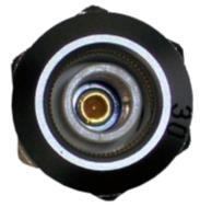

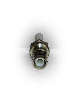
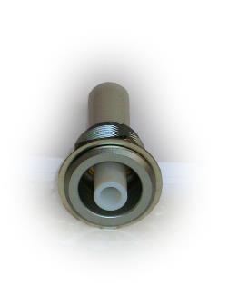

52 Accessories: High voltage sockets SHV panel connector RA 3415 HB 21 RA 3430 B
 are included in the delivery of the unit. Additional connectors (as shown in page 51) can be delivered on request.")


53 Accessories: High voltage connectors Provided plugs and matching cables for FuG power supplies SHV- cable jack For all medium and high voltage power supplies, the appropriate output connectors, as mentioned in the table (excluding banana plugs) are included in the delivery of the unit. Additional connectors (as shown in page 51) can be delivered on request. For power supply types, not listed in the below table, the output will be designed with special high voltage sockets, chopper bars or clamps. As far as necessary the mating plugs will be also included in the delivery. F 3415 Type Connector type Quantity included Stock number matching cable Comment MCA to MCA SHV cable jack RG 58 MCA to MCA SHV cable jack RG 58 MCP to MCP SHV cable jack RG 58 MCP to MCP SHV cable jack RG 58 MCP to MCP SHV cable jack RG 58 MYN SHV cable jack RG 58 HS 21 F 3430 HCP to HCP SHV cable jack RG 58 HCP to HCP SHV cable jack RG 58 HCP to HCP HS HCP to HCP HS HCP to HCP F 3430 AG 10, RG 11 HCP to HCP F 3430 AG 10, RG 11 HCP to HCP HVS C 2124 inclusive 3m cable HCP to HCP HVS C 2124 inclusive 3m cable HCP to HCP HVS C 2121 inclusive 3m cable HCH SHV cable jack RG 58 HCH and HCH SHV cable jack RG 58 HCH to HCH SHV cable jack RG 58 HCH to HCH SHV cable jack RG 58 HCH to HCH F 3415 AG 6, HCH to HCH F 3430 AG 10, RG 11 HCH to HCH F 3430 AG 10, RG 11 HCH to HCH HVS C 2124 inclusive 10m cable HCH to HCH HVS C 2124 inclusive 10m cable HYN to HYN SHV cable jack RG 58 HYN Copper busbar HYN to HYN SHV cable jack RG 58 HYN to HYN F 3415 AG 6, HYN to HYN F 3430 AG 10, RG 11 HCE to HCE SHV cable jack RG 58 HCE to HCE SHV cable jack RG 58 HCE to HCE SHV cable jack RG 58 HCE to HCE SHV cable jack RG 58 HCE to HCE F 3415 AG 6, HCE to HCE F 3415 AG 6, HCE to HCE F 3430 AG 10, RG 11 HCK to HCK SHV cable jack RG 58 HCK to HCK SHV cable jack RG 58 HCK to HCK F 3415 AG 6, HCK F 3430 AG 10, RG 11 HCK to HCK F 3415 AG 6, HCK to HCK F 3430 AG 10, RG 11 HCK to HCK S 150 Teflon C 2032 SNJ HCK to HCK HVS 65 Teflon C 2184 incl. cable S 150, HVS 65, HVS 100, HVS 150 (Difference only in length) HCB 1, to HCB SHV cable jack RG 58 HCB to HCB F 3415 AG 6, HCB to HCB F 3430 AG 10, RG 11 53
54 Definitions and Terms Absolute accuracy The stated figure refers to the absolute deviation of the DVM, or of the monitors of the analog programming. They are independent of the stability data of the individual series. For all families with standard data the following absolute accuracy values apply: for all nominal voltages: < ± 0,2% of the nominal value for all nominal currents within the range > 5mA up to < 200A: < ± 0,2% of the nominal value without this range: < ± 0,5% of the nominal value additional error of the DVM: < ± 2 Digits Active pull-down control Available on demand especially for the NLN series: Power transistors parallel to the output acting as a current sink. Autoranging power supply Power supply with automatic ranging of the operating point. without steps. These power supplies can provide any combination of the rated current and voltage - limited only by the rated maximum available output power. Bipolar power supply A bipolar power supply can be adjusted from positive output voltage and current to negative with continuous zero crossing. All bipolar power supply units of FuG Elektronik GmbH are designed for restricted 4-quadrant operation. The electrical power stored within the load can be subsequently reabsorbed by the power supply. On request the units can be equipped for full 4- quadrant capability. CE mark All FuG- power supplies have a CE label - a guarantee of compliance with the current EMC and safety standards. Certificate of calibration All FuG- power supplies can be calibrated at the factory. The certificate of calibration, which can be supplied on request, confirms the compliance of the output data with the catalogue data: Indication on the DVM Monitor voltages*) Computer output data*) Reference voltage*) Linear coherence between control voltage and output value*) *) Options Charging current FuG- capacitor charging power supplies operate with constant current. It is adjustable to every value up to the nominal value. On request, units are available with enhanced charging current at low voltage. Charging power Power specification for capacitor charging power supplies. The data is in J/s, and is valid for charging from "0" to the nominal voltage. For charging of a partially discharged capacitor a considerably higher charging power, up to double, can be supplied. Chopper controlled See Switch mode power supply. Deviation (Stability data) This term is always referred to the nominal parameter value and is valid for operation under constant operating conditions. Constant operating conditions means that, in each case, all other conditions such as the load, ambient temperature and mains voltage are constant: a) Deviation of the output voltage (or output current when specified) for ±10% variation of the line voltage. b) Deviation of the output voltage (or output current when specified) over a period of 8 hours, after an appropriate warm up time. c) Deviation of the output voltage at load changes from full load to no load. Discharge time constant This data always relates to the unconnected output. It is the time taken for the output voltage to decay to approx. 37% of the adjusted voltage after the output has been switched off. Double stabilized power supply Such units are equipped with a thyristor pre-regulator followed by a linear transistor regulator stage. The high efficiency of the thyristor pre-regulator stage is combined with the high regulation characteristics of a linear regulator. Dump switch Rapid discharge switch for the controlled discharging of internal and external capacitors. (see also Interlock) Efficiency The efficiency of the units depends on the respective operating point. At full load a figure of 85-95% will be reached with switched and thyristor regulated power supplies,whilst 70-90% is achievable with linear regulated power supplies with thyristor pre-regulation. Electronic load A unit, which has the behaviour of an adjustable load resistor. Usually, it is used for testing power supplies. Depending on the design, it is possible to adjust and regulate the resistance, the load power or the load current. FuG offers customized electronic loads on request. EMC Electro Magnetic Compatibility. See Regulations and Standards. EURO-size 19" cassette system cases, 3U Fast de-energizing Option for super conductor supplies for controlled deenergization of super conducting coils/magnets at quench. Final charging voltage Preset voltage for capacitor charging power supplies up to which the capacitor shall be charged. Floating output The specified output terminals have no DC connection to other parts of the unit or to ground. The maximum potential difference (isolation voltage) is indicated. IMS-size Older size of plug-in cases, 4U Interlock Loop for switching off the output voltage when disconnected. Mains disconnection of the power stage, but without any forced discharging of the output or load. (see also dump switch) ISO 9001 Since 1994 FuG has maintained this quality assurance system. All supplied units are tested (using calibrated measuring instruments) and the results are recorded in our test department, so as to ensure that all units shipped are fully in accordance with their specification. Linear regulation Control of energy flow by one or more of bipolar or field effect transistors which are switched in series to the load and operated with the linear part of their characteristic. Mains connection Stated is the mains voltage, the permissible tolerance (±10%), the line frequency range and the type of mains connection, e.g. single phase, two-phase or three-phase. Connection of N (neutral) and PE (protective earth) are always necessary. Nominal current Maximum available current. Nominal power Maximum available power from the power supply. No higher power is available - even for a short time. For FuG- power supplies the first number in the type name is the power class or the main component of the power supply. This value is approximately (but may be not exactly) the nominal power. 54
55 Definitions and Terms Nominal voltage Maximum adjustable voltage. For FuG- power supplies the second number in the type name is usually the nominal voltage of the power supply. Operational conditions As far as not otherwise stated in the manual, for Fug power supplies the following conditions are valid: Temperature: 0 to +40 C Humidity: 0 to 85% not condensing Height over sea level: max. 2000m Output isolation On units where the "0V" terminal is not firmly connected to earth (or may be optionally disconnected from earth), it is always shown up to which maximum voltage the terminal may be allowed to float with respect to earth. For units with floating output (all low and medium voltage power supplies up to 2kV - except cassettes) this value is valid for either of the output terminals. PROBUS FuG name for our system of computer interfaces. PWM-Regulator Regulator utilising Pulse Width Modulation. Such regulators are used in switch mode power supplies and in drives. Quench The transition of a super conducting coil / magnet from super conducting to normally conducting condition. If no special measures are taken, the energy, stored in the magnetic field, will be converted into thermal energy, within a short time, when quench occurs. Quench detector Circuit to detect a quench. Recovery time This characteristic is stated independently for voltage and current: For voltage control, it is the time which the power supply requires to return to the adjusted voltage after a load variation from 10% to 100%, or from 100% to 10%. For current control, it is the time which the power supply requires to return to the adjusted current after a load variation where the output voltage does not change by more than 10% of the nominal voltage. Regulation mode Standard power supplies can be operated in constant voltage mode or constant current mode. Switching over takes place automatically with sharp transition. For FuG power supplies the regulation mode is displayed on the front plate by LEDs. Regulations and standards The design and production of our power supplies is in accordance with the latest standards for EMC and safety. Depending on the type of the respective unit, different standards are valid: EMC: EN and EN (single-phase mains connection) EN and EN (two- and three-phase mains connection) Safety: EN Repetition frequency This frequency corresponds to the repetitive charge and discharge of a capacitor by a capacitor charging power supply. The reproducibility of the end-of -charge voltage depends on the repetition frequency. Reproducibility Repeatability of setting of a desired output value under constant conditions - it is always referred to the nominal value of the supply. Residual Ripple If not otherwise stated the residual voltage ripple is the referredto parameter. It is always referred to the nominal value independent of the set value. The frequency of the ripple is the frequency of the mains rectifier and its harmonics. For chopper controlled units there is also a component of the switching frequency (usually 20kHz/40 khz). For capacitor charging power supplies the value of the charging current is the referredto parameter. For FuG- power supplies the residual ripple usually is stated as Peak to peak. ( p-p ) value. It is different to the RMS value since this measurement also takes into account the short term voltage peaks on full scale. RMS The energetically equivalent DC value (also effective value) to an alternating voltage. It corresponds to the square root of the integral of squares (Root Mean Square). For a purely sinusoidal voltage the rms value corresponds to about 36% (1/(2x 2)) of the "peak-to-peak" value. At a pulse range consisting of narrow peaks (which is typically the case for the residual ripple of a switched mode power supply) the difference can be considerably larger. Safety See Regulations and Standards. Sense terminals For low voltage power supplies, sense lines can be connected to these terminals to measure the voltage immediately at the load and by this to compensate for any voltage drop on the loadlines. The nominal output voltage always refers to the actual output terminals and does not take account of any voltage drop on the load-lines. The compensation of the voltage drop on the load-lines is restricted to a maximum of 5% of the nominal voltage (minimum of 1V) and has to be considered when choosing a supply. Setting resolution Smallest possible steps for the adjustment of voltage or current - always referred to the nominal value. Setting time The time required before the output value of a power supply reaches the set value in the limits of the stated tolerance. Stability See deviation. Standards See Regulations and Standards. Switch mode power supply Power supply where the transmission of energy is performed by high frequently alternating voltage. Temperature coefficient (Tc) In addition to the value for longterm stability (see deviation), we also refer to the 'drift' of an output value as a function of the variation in the ambient temperature whilst the supply is operating under otherwise constant conditions. The data is specified as 'per Kelvin' and is only valid within the stated operating temperature range. The Tc is always referred to the nominal value. When the option "higher stability" is integrated, then the Tc figure improves. Thyristor regulation Control of energy flow by a phase cutting circuit with thyristors, operating at the frequency of the mains input. Unipolar power supply Units with only one polarity and with no regulation through zero. Warm-up time Stability data is only valid after a warm-up time of min. 30 minutes. 2-quadrant operation The unit operates as a current source and also as current sink (electronic load) with only one polarity of the output voltage. (See active pull-down.) 4-quadrant operation The unit operates as a current source and also as current sink (electronic load) with both polarities of the output voltage. (See also bipolar power supply.) 55


56 Examples for customer specific power supplies: We design and manufacture according to your requests! MCP Medium voltage precision power supply Equipped with the options: coarse/fine potentiometers for voltage and current, digital interface, analog programming and power limitation. HCV 3,1M Power supply for VUV- Spectrometer 3 outputs in series: 0 - ±100V; 0-1mA V; 0-1mA V; max. 0,1mA HCV 57M Multiple output high voltage supply 19 voltage sources with 11 output voltages from 6kV to 20kV NLV 27M Power supply for beam deflection 5 double outputs with counter moving voltages: 0 - ±400V; max. 1mA 56


 HCN7E - 7000 Customer specific test equipment")


57 Examples for customer specific power supplies: We design and manufacture according to your requests! MCP Power supply for undersea applications 0-1,1kV, 0-1A With two separate switchable outputs, isolated and monitored, Wide input range 85V - 265V HCV 349M High voltage supply for backward wave tube 0-6,5kV, 0-50mA With floating heater supply Special design for airborne use (vibration hard) HCN7E Customer specific test equipment 0-7kV, max. 1mA With test pistol HCE 2,4M Customer specific high voltage module 0-12kV, max. 200µA For picture tube testing HCM 7, Customer specific high voltage module Bipolar 0 - ± 30kV, 0 - ±0,25mA For mass spectrometers NTN 100M - 12,5 Isolated low voltage power supply 0-12,5V, 0-8A Designed for floating operation up to 20kV HCN 35M Insultation Tester 0-70kV, 0-0,5mA Two high-resolution current measurement circuits. 57

 Two")

 for klystron supply of a")
58 Examples for customer specific power supplies: We design and manufacture according to your requests! HCK 800M Cable Tester 13kV / 120mA Many special functions HCN 12900M High voltage power supply 300kV, 60mA (Fold back to 35mA at full voltage) Two additional 12.5kV supplies installed for clearing electrodes For the operation of an electrostatic septum for particle accelerators HCK 50000M pieces of Capacitor charging power supplies 50kV, 2A Very high reproducibility (10ppm) for klystron supply of a free electron laser HCK 150M Capacitor charging power supply For lightning-arrestor test bench 100kV / 3mA Special version: Output via brass ball 58

 For the calibration of the power supply two high precision voltage dividers are included (right and left) HCV 141510M - 40000 Power supply for IOT (Inductive Output Tube) Anode voltage 40kV with")
59 Examples for customer specific power supplies: We design and manufacture according to your requests! HCV 4200M Double High voltage power supply for X-Ray tube Two symmetrical outputs: 0 to +200kV und 0 to -200kV. Additional output for anode heater, floating on negative output potential. Regulation loops for voltage control, current control and emission current control. (Regulation loop is closed via filament current.) For the calibration of the power supply two high precision voltage dividers are included (right and left) HCV M Power supply for IOT (Inductive Output Tube) Anode voltage 40kV with max. 3,4A Additionally, all auxiliary supplies necessary for the operation of the tube, such as heating, grid bias voltage and focusing, are provided. The electromagnetic field generated by the IOT is used to accelerate electrons for a synchrotron radiation standard to a accurate defined distinct energy. 59
60
Power Conversion Systems 2005/2006. Schaefer the Power to make it happen.
 Power Conversion Systems 2005/2006 Schaefer the Power to make it happen. Company profile workforce experience customer orientation flexibility reliability Schaefer Elektronik, founded in 1969, has grown
Low Profile DC Power Supply with Zero Voltage Soft Switching
 Sorensen XFR Series Low Profile DC Power Supply with Zero Voltage Soft Switching Analog programming Zero voltage soft switching Constant voltage or constant current operation with automatic crossover and
Sorensen XG 1700 Series 1700 W A Watt, 1U Programmable DC Power Supplies V. Key Features. Key Modes
 Sorensen XG 1700 Series 1700 W 1700 Watt, 1U Programmable DC Power Supplies 6 600 V Industry Leading Power Density Up to 1700 Watts in 1U Standard Digital Interfaces USB&RS232/485 LXI Ethernet and Isolated
KEPCO Will Point You In The Right Direction!
 Looking For A High Power, Low Profile Power Supply? KEPCO Will Point You In The Right Direction! -9 AN ISO 900 COMPANY You'll Always Find What You Need At Kepco KLN Series Programmable Power Supply: 0W
Models. Output current max.* Output Power max. Low Line : VAC High Line: VAC 24 VDC / 12 A 240 W. Back up battery
 AC/DC Battery Controller Power Supply TSPC-240UPS Series Compact universal 24 VDC power supply with integrated battery controller module Battery protection for over voltage, deep discharge, short circuit
SPECIFICATIONS UPS Triple Output 13.6VDC/213W, 48VDC/153W, 48VDC/39W
 Page 1 / 7 Full operation without need of battery Two independent 48Vdc outputs for switching and control Local monitoring with 8 LEDs Remote monitoring with 4 alarm relays Monitoring and configuration
Sorensen XG Series / XTR Series W A. 850 W, 1U Half Rack Programmable DC Power Supplies V
 Sorensen XG Series / XTR Series 670 850 W 850 W, 1U Half Rack Programmable DC Power Supplies 6 600 V Highest Power Density Comprehensive Digital and Analog Interface Options Scalable, Multi-Unit Design
The 3 kw Models will accept 200*/230 VAC single phase and 200*/208 VAC three phase input power.
 Sorensen DLM 3 & 4 kw Series DC Power Supply High Power Density : 3 kw and 4 kw models, 2U (3½ high), (19 wide); no top or bottom clearance spacing required Preview Push-button : Overvoltage protection
The Z Series. SCR Power controllers for resistance heating applications. Zero-Fired SCR Power Controllers AMPS VAC
 The Z Series Zero-Fired SCR Power Controllers 60-1200 AMPS 120-600 VAC SCR Power controllers for resistance heating applications. ROBICON 1996 Rev. 7/96 Applications Robicon s Z series power controls are
ALR output Powerfull PROGRAMMABLE POWER SUPPLY 640 WATTS 0-32V 0-20A POWERFUL. Specifications
 $ PROGRAMMABLE POWER SUPPLY EAN CODE : 3760244880062 1 output Powerfull POWERFUL ALR3220 VISUAL : Large graphic display SOFT-TOUCH : Sensitiv keypad CONNECTED : USB, RS232, RS485 & 0-10V isolated LabVIEW
World Class Power Solutions. Rectifiers. For Stationary Battery Systems in Nuclear Power Plants
 World Class Power Solutions Rectifiers For Stationary Battery Systems in Nuclear Power Plants General 2 1.1 Application Electronically controlled rectifier assemblies are used in conjunction with suitable
Central Battery Systems Loadstar AC/DC Systems
 The Loadstar range of AC/DC central battery units comply with the latest relevant European and British standards. High quality, cost effective units provide secure sources of emergency power for escape
POWER kva
 TECHNICAL DATA SHEET B9000 FXS 60-80-100-125-160kVA +44 (0)20 8868 3732 GENERAL INFORMATION UPS Type ON LINE Double Conversion Nominal output power (Cos φ 0,8) kva 60 80 100 125 160 Nominal output power
SECTION DC POWER SUPPLY/BATTERY CHARGER
 SECTION 26 33 05 PART 1 - GENERAL 1.1 THE REQUIREMENT A. The CONTRACTOR shall provide the single-phase heavy-duty industrial battery charger and all accessories required, complete and operable, in accordance
& HIGH CURRENT DC POWER SUPPLIES INSTRUCTION MANUAL
 72-6850 & 72-6852 HIGH CURRENT DC POWER SUPPLIES INSTRUCTION MANUAL Table of Contents Introduction 2 Specification 2 Safety 4 EMC 5 Installation 6 Connections 6 Operation 7 Maintenance and Repair 8 www.tenma.com
PPS20 COMMUNICATIONS POWER SUPPLY AND BATTERY MANAGEMENT SYSTEM
 PPS20 COMMUNICATIONS POWER SUPPLY AND BATTERY MANAGEMENT SYSTEM 2 Table of Contents Introduction:... 3 1.0: Operation Principles:... 3 1.1: Stand alone supply... 3 1.2: Backed up supply:... 3 1.3: Battery
Industrial Chargers and
 Industrial Chargers and DC Systems SPR - Single Phase Rectifier TPR - Three Phase Rectifier 12V 250V 5A 1000A Designed for all Industrial applications Oil & Gas, Petrochemicals Offshore, Onshore, Pipelines
Three Phase UPS Systems Range: 10 to 500kVA
 Three Phase UPS Systems Range: 10 to 500kVA Three Phase UPS Systems Hitachi Hi-Rel Power Electronics Pvt. Ltd. is in the business of Industrial UPS Systems since 1987 and has rich experience in supplying
Industrial PFC UPS System
 Based on Statron s leading A.T.I.S. (Advanced Technology Industrial System) platform, the S3000 range is a true-industrial UPS system using the latest Power Factor Corrected (PFC) IGBT rectifier technology.
POWER kva Nominal output power (Cos φ0,8) kva Nominal output power (Cos φ1,0) kw >88 Efficiency (AC AC)
 kva Nominal output power (Cos φ1,0) kw >88 Efficiency (AC AC)") TECHNICAL DATA SHEET B9000 FXS 200-250 - 300kVA +44 (0)20 8868 3732 GENERAL INFORMATION UPS Type ON LINE - Double Conversion Nominal output power (Cos φ0,8) kva 200 250 300 Nominal output power (Cos φ1,0)
TECHNICAL DATA SHEET B9000 FXS 200-250 - 300kVA +44 (0)20 8868 3732 GENERAL INFORMATION UPS Type ON LINE - Double Conversion Nominal output power (Cos φ0,8) kva 200 250 300 Nominal output power (Cos φ1,0)
Eaton 93PS 8-40kW UPS Technical Specification Manufacturer s declaration in accordance with IEC
 Manufacturer s declaration in accordance with 8- Frame Model catalogue reference 93PS-XX(20)-YY- 93PS-XX(40)-YY- Number of power modules (UPM) 1 1 or 2 Number of internal batteries 0 to 2 x 32 blocks 0
Power Conversion Systems. SCHAEFER International. Switchmode Power Supplies, Chargers & Inverters. Thyristor-controlled Power Supplies & Chargers
 SCHAEFER International Power Conversion Systems Innovation made in Germany SCHÄFER Elektronik GmbH Oststrasse 17, Gamshurst 77855 Achern Germany Phone +49 (0)7841-2052-0 Fax +49 (0)7841-2052-52 mail@schaeferpower.de
TECHNICAL DATA SHEET B8033FXS kva 3Ph(In) 3Ph(Out)
 3Ph(Out)") TECHNICAL DATA SHEET B8033FXS 10 15 20 kva 3Ph(In) 3Ph(Out) GENERAL INFORMATION UPS Type ON LINE Double Conversion Nominal output power (Cosϕ 0.9) kva 10 15 20 Nominal output power (Cosϕ 1.0) kw 9 13.5
TECHNICAL DATA SHEET B8033FXS 10 15 20 kva 3Ph(In) 3Ph(Out) GENERAL INFORMATION UPS Type ON LINE Double Conversion Nominal output power (Cosϕ 0.9) kva 10 15 20 Nominal output power (Cosϕ 1.0) kw 9 13.5
EPS/ELA-Series User Manual EPS/ELA 250W
 EPS/ELA-Series User Manual EPS/ELA 250W EPS Stromversorgung GmbH Tel: +49 (0)821 570451 0 Index 3 Page: 1 Table of contents: Page 1. Features of ELA-Series... 3 1.1 Basic Functions... 3 1.2 Options...
POWER kva
 +44 (0)20 8868 3732 TECHNICAL DATA SHEET B9600 400-800kVA GENERAL INFORMATION UPS Type ON LINE - Doppia Conversione Nominal output power (Cos φ0,8) kva 400 500 600 800 Nominal output power (Cos φ1,0) kw
MASTERYS IP+ 10 to 80 kva
 MASTERYS IP+ 10 to 80 kva OBJECTIVES The aim of these specifications is to provide: the information required to choose the right uninterruptible power supply for a specific application. the information
EFFEKTA Power Supplies
 EFFEKTA GENERAL INFORMATION UPS topology ON LINE - Double Conversion Classification VFI-SS-111 in accordance with IEC 62040-3 Nominal output power (Cos Ø 0,9) - kva 10 15 20 30 40 Nominal output power
TECHNICAL DATA SHEET B8031 FXS kva 3Ph(In) 1Ph(Out)
 1Ph(Out)") TECHNICAL DATA SHEET B8031 FXS 10 15 20 kva 3Ph(In) 1Ph(Out) GENERAL INFORMATION UPS Type ON LINE Double Conversion Nominal output power (Cos 0.9) kva 10 15 20 Nominal output power (Cos 1.0) kw 9 13.5
TECHNICAL DATA SHEET B8031 FXS 10 15 20 kva 3Ph(In) 1Ph(Out) GENERAL INFORMATION UPS Type ON LINE Double Conversion Nominal output power (Cos 0.9) kva 10 15 20 Nominal output power (Cos 1.0) kw 9 13.5
MaxPak Plus Analog DC V S Drive
 Three-Phase 3-600 HP non-regenerative and 5-150 HP regenerative drives Designed to accommodate a wide range of industrial requirements, the DC V S Drive has been widely applied worldwide. Selected ratings
Technical Data Sheet. Uninterruptible Power Supply. Critical Power. imagination at work
 Technical Data Sheet Uninterruptible Power Supply TLES_040-120_S1_UPS_GE_Floor_01 GE Consumer & Industrial SA General Electric Company CH 6595 Riazzino (Locarno) Switzerland T +41 (0)91 / 850 51 51 F +41
Electropneumatic pressure regulator EPP4 Series
 Electropneumatic pressure regulator EPP4 Series Connection G ¼ Catalogue 8683/UK The ECONOMIC solution which meets the market requirements Compact design and lightweight for ease of installation and low
Technical Data Sheets
 GE Consumer & Industrial Technical Data Sheets Digital Energy Uninterruptible Power Supply SG-CE Series 160 200 250 300 kva PurePulse TM 400 Vac CE Series 1 Date of issue: 15.02.2007 SGSE160-200S1UPS01
Power Quality Solutions POWER QUALITY SOLUTIONS: ACTIVE HARMONIC FILTERS
 Power Quality Solutions 2018 POWER QUALITY SOLUTIONS: ACTIVE HARMONIC FILTERS ACTIVE Ematic FA40 New Series ICAR: products and solutions Founded in 1946, ICAR is a leading manufacturer of capacitors and
Technical Data Sheets
 GE Consumer & Industrial Power Protection Technical Data Sheets Digital Energy Uninterruptible Power Supply SitePro 150 200 250 300 kva 400 VAC CE Series 6 Manufactured by: GE Digital Energy General Electric
Electronic Ballast EVG 2000-T
 Electronic Ballast EVG 2000-T Operating Manual Table of contents 1 Description 1.1 Advantages of this ballast... 3 1.2 Functional principle... 3 1.3 Energization... 4 1.4 Visualization... 5 1.5 Indications
IRT 4000 AT-S/M/L. Technical Manual. quality IN MOTION. quality IN MOTION
 IRT quality IN MOTION www.irtsa.com 4000 AT-S/M/L Technical Manual IRT quality IN MOTION E2 0 8 4 1 5 September 2013-Rev. 5 UL Requirements Drives Series 2000 / 4000 AT 1. Field wiring terminal to use
TELECOM- MUNICATIONS DEVICES INDUSTRIAL EMERGENCY DEVICES. (Servers Farms, ISP/ASP/POP)
") Local Area Networks (LAN) ServerS DATA CENTRES CASH REGISTERS TELECOM- MUNICATIONS DEVICES e-business (Servers Farms, ISP/ASP/POP) INDUSTRIAL PLCs ELECTRO- MEDICAL DEVICES EMERGENCY DEVICES (Lights/Alarms)
Local Area Networks (LAN) ServerS DATA CENTRES CASH REGISTERS TELECOM- MUNICATIONS DEVICES e-business (Servers Farms, ISP/ASP/POP) INDUSTRIAL PLCs ELECTRO- MEDICAL DEVICES EMERGENCY DEVICES (Lights/Alarms)
Switching Power Supplies
 Features Boxed Power Supplies with Screw Terminal Block Single- and Triple Output Models EMI Compliance with EN 55022 and FCC Part 15, Level B Short Cirquit Protection Overvoltage Protection High Efficiency
Electropneumatic pressure regulator EPP4 Series. Connection G ½. Catalogue 8684/UK G ½"
 Electropneumatic pressure regulator EPP4 Series Connection G ½ Catalogue 8684/UK G ½" The ECONOMIC solution which meets the market requirements Compact design and lightweight for ease of installation and
Kelly HSR Series Motor Controller with Regen User s Manual V 3.3. Kelly HSR Opto-Isolated Series Motor Controller with Regen.
 Kelly HSR Opto-Isolated Series Motor Controller with Regen User s Manual HSR72601 HSR72801 HSR12401 HSR12601 HSR12901 HSR14301 HSR14501 HSR14701 Rev.3.3 Dec. 2011 Contents Chapter 1 Introduction... 2 1.1
5001TCP SPEED CONTROLLER
 VARIABLE SPEED DRIVE CONTROLLER INSTALLATION AND SETTING UP MANUAL 5001TCP SPEED CONTROLLER With PC101 Torque Limit Control WARNING Disconnect all incoming power before working on this equipment. Follow
C1000 Series Automatic Cap Bank
 C1000 Series Automatic Cap Bank Metal Enclosed - Medium Voltage Capacitors Assemblies Fixed / Auto Medium Voltage 5, 15, 25 and 35 kv Class Customized to your specifications The Reactive Power Solution
BC-2014 ULTRA COMPACT 4-BAY SMART BATTERY CHARGER (Military Grade)
") BC-2014 ULTRA COMPACT 4-BAY SMART BATTERY CHARGER (Military Grade) Especially suitable for Naval use, 19 Rack Type, with IP- 67 protection class. Made to H: 125 mm W: 275 mm D: 250 mm Up to 4 batteries
BC-2014 ULTRA COMPACT 4-BAY SMART BATTERY CHARGER (Military Grade) Especially suitable for Naval use, 19 Rack Type, with IP- 67 protection class. Made to H: 125 mm W: 275 mm D: 250 mm Up to 4 batteries
nonstopower sdn bhd ( P) Power Management Instruments DC Battery Charger / Automation Type RELIABLE SOLUTIONS in POWER ELECTRONICS
 Power Management Instruments DC Battery Charger / Automation Type RELIABLE SOLUTIONS in POWER ELECTRONICS") RELIABLE SOLUTIONS in POWER ELECTRONICS Power Management Instruments DC Battery Charger / Automation Type Distributed by : nonstopower sdn bhd (822490-P) no. 78 & 80, jalan rimbunan raya, laman rimbunan,
RELIABLE SOLUTIONS in POWER ELECTRONICS Power Management Instruments DC Battery Charger / Automation Type Distributed by : nonstopower sdn bhd (822490-P) no. 78 & 80, jalan rimbunan raya, laman rimbunan,
Professional Wireless Products
 Page 1 of 6 093115 Communications Power Supply and Battery Management Controller Page 2 of 6 1.0 Introduction The 093115 is a 13.8 volt 15amp transformer isolated switch mode down converter designed to
Very high efficiency up to 93% Adjustable output voltage
 The Bel Power Solutions 700DNC40-24-xG is a 4 kw DC/DC converter that creates DC voltages in hybrid and electric vehicles necessary to power low voltage accessories. Liquid or convection cooled DC/DC converter
Model ESV Uninterruptible Power System 1.5 KVA/KW KVA/KW Single Phase
 Model ESV Uninterruptible Power System 1.5 KVA/KW - 14.0 KVA/KW Single Phase 1.0 General General Specification This specification describes the features and design of an on-line, dual conversion, uninterruptible
TELECOM- MUNICATIONS DEVICES INDUSTRIAL EMERGENCY DEVICES. (Servers Farms, ISP/ASP/POP)
") LOCAL Area Networks (LAN) ServerS DATA CENTRES CASH REGISTERS TELECOM- MUNICATIONS DEVICES e-business (Servers Farms, ISP/ASP/POP) INDUSTRIAL PLCs ELECTRO- MEDICAL DEVICES EMERGENCY DEVICES (Lights/Alarms)
LOCAL Area Networks (LAN) ServerS DATA CENTRES CASH REGISTERS TELECOM- MUNICATIONS DEVICES e-business (Servers Farms, ISP/ASP/POP) INDUSTRIAL PLCs ELECTRO- MEDICAL DEVICES EMERGENCY DEVICES (Lights/Alarms)
Power Supplies. SDN-C Compact DIN Rail Series
 SDN-C Compact DIN Rail Series The SDN-C DIN rail power supplies are the next generation of the popular SDN series. These models combine high effi ciency and compact size with new visual diagnostic LEDs
5001TCP SPEED CONTROLLER
 INSTALLATION AND SETTING UP MANUAL 5001TCP SPEED CONTROLLER WARNING Disconnect all incoming power before working on this equipment. Follow power lockout procedures. Use extreme caution around electrical
Lexium integrated drives
 Description ILp for CANopen, PROFIBUS DP, RS ILE with brushless DC motor Description ILE comprise control electronics with a fieldbus interface for CANopen DS, PROFIBUS DP or RS and a brushless DC motor.
SD700FR. Regenerative Active Front End VARIABLE SPEED DRIVES POWER ELECTRONICS / SD700 SERIES 4 QUADRANT. icool
 FR VARIABLE SPEED DRIVES Regenerative Active Front End icool 4 QUADRANT POWER ELECTRONICS / SD700 SERIES FR SD700FR SERIES goes one step ahead keeping the family unique characteristics. Based on the latest
TECHNICAL DATA SHEET INFINITY kva 3Ph(in) 3Ph(out)
 3Ph(out)") TECHNICAL DATA SHEET INFINITY 3300 10 15 20 kva 3Ph(in) 3Ph(out) GENERAL INFORMATION POWER - kva 10 15 20 UPS typology ON LINE Double conversion ACTIVE stand by-operation (Optional) Nominal output power
TECHNICAL DATA SHEET INFINITY 3300 10 15 20 kva 3Ph(in) 3Ph(out) GENERAL INFORMATION POWER - kva 10 15 20 UPS typology ON LINE Double conversion ACTIVE stand by-operation (Optional) Nominal output power
SD, SE, SDE, SCO series Multipole switchgear for rail vehicles: Disconnecting switches, Earthing Switches, Disconnector with Earthing Switches,
 4 Electrics for Rolling Stock Multipole switchgear for rail vehicles: Disconnecting switches, Earthing Switches, Disconnector with Earthing Switches, Change-Over-Switches 600 V to 3 kv Catalogue F84.en
Powerframes - Power Electronics
 Powerframes - Power Electronics 70 series The study of power electronic devices, motor drives and circuits is an essential part of any course on power electrical systems. The Series 70 Power Electronics
LINEAR LED DRIVERS. ComfortLine Selectable Current (Output Terminal) ComfortLine SELECTABLE CURRENT (OUTPUT TERMINAL)
 ComfortLine SELECTABLE CURRENT (OUTPUT TERMINAL)") LINEAR LED DRIVERS ComfortLine SELECTABLE CURRENT (OUTPUT TERMINAL) 186443, 186444, 186486, 186487, 186488, 186491, 186492, 186737 Typical Applications Built-in in linear luminaires for Office lighting
LINEAR LED DRIVERS ComfortLine SELECTABLE CURRENT (OUTPUT TERMINAL) 186443, 186444, 186486, 186487, 186488, 186491, 186492, 186737 Typical Applications Built-in in linear luminaires for Office lighting
ABB Softstarter Benefits Charnchanok Thongprad
 ABB Softstarter Benefits Charnchanok Thongprad tomation Technology Products AB Control - 1 - - Why Softstarters? Benefits for the Electrical network Reduces voltage drops on networks Minimizes starting
RELIABLE SOLUTIONS in POWER ELECTRONICS. Power Management Instruments RDAT SERIES BATTERY CHARGER / DC RECTIFIER PMI / GESS / KARMET GROUP COMPANIES
 RELIABLE SOLUTIONS in POWER ELECTRONICS RDAT SERIES Power Management Instruments BATTERY CHARGER / DC RECTIFIER PMI / GESS / KARMET GROUP COMPANIES BATTERY CHARGER / DC RECTIFIER RDA / RDAT AUTOMATION
ELECTRICAL INTERFACE TO DC BRUSHLESS MOTORS SUPPLIED IN TECNADYNE THRUSTERS, LINEAR & ROTARY ACTUATORS & HPU s
 Tecnadyne Application Note AN605 5/12/2006 Page 1 of 5 ELECTRICAL INTERFACE TO DC BRUSHLESS MOTORS SUPPLIED IN TECNADYNE THRUSTERS, LINEAR & ROTARY ACTUATORS & HPU s 1. Introduction The electrical interface
Technical Data Sheet. Uninterruptible Power Supply. Critical Power. imagination at work
 Technical Data Sheet Uninterruptible Power Supply SGSE_010-040_S1_UPS_GE_01 GE Consumer & Industrial SA General Electric Company CH 6595 Riazzino (Locarno) Switzerland T +41 (0)91 / 850 51 51 F +41 (0)91
Low voltage AC drives. ABB micro drives ACS to 3 hp/0.18 to 2.2 kw Catalog
 Low voltage AC drives ABB micro drives ACS55 0.25 to 3 hp/0.18 to 2.2 kw Catalog ACS55 IP20 Overview ACS55 micro drives are designed for use in a wide variety of simple machinery applications where only
Adjustable Torque Controls
 MCS0 Adjustable Torque Control The MCS0 is an enclosed control complete with a cover and mounting provisions. A brake and clutch may be operated separately with this control or up to four units, two at
651 SERIES POWER CONTROL UNITS Single Phase, Phase Angle SCR Controller
 651 SERIES POWER CONTROL UNITS Single Phase, Phase ngle SCR Controller STNDRD FETURES Electronic design utilizing Large Scale Integration. Phase lock loop for firing pulse synchronization. Standard ratings
Technical Data Sheets
 GE Consumer & Industrial Power Protection Technical Data Sheets Digital Energy Uninterruptible Power Supply SitePro 400 & 500 kva 400 VAC CE Series 6 Manufactured by: GE Digital Energy General Electric
Dynamic PFC:Thyristor Modules TSM Series
 Dynamic PFC:Thyristor Modules TSM Series P o w e r Q u a l i t y S o l u t i o n s www.epcos.com/pfc The collection of PQS is a library with in-depth information on PFC applications, case studies and reference
4/3 proportional directional control valve, without position control, with on-board electronics (OBE)
") 4/3 proportional directional control valve, without position control, with on-board electronics (OBE) Type 4WRBAE..E.. /..W.. Nominal size (NG) 6, 10 Unit series 2X Maximum working pressure P, A, B 315
4/3 proportional directional control valve, without position control, with on-board electronics (OBE) Type 4WRBAE..E.. /..W.. Nominal size (NG) 6, 10 Unit series 2X Maximum working pressure P, A, B 315
AF series contactors (9 2650)
") R E32527 R E39322 contactors General purpose and motor applications AF series contactors (9 2650) 3- & 4-pole contactors General purpose up to 2700 A Motor applications up to 50 hp, 900 kw NEMA Sizes 00
R E32527 R E39322 contactors General purpose and motor applications AF series contactors (9 2650) 3- & 4-pole contactors General purpose up to 2700 A Motor applications up to 50 hp, 900 kw NEMA Sizes 00
M Series 140.D Data Sheet. Two-Point Controller with Moving-Iron or Moving-Coil Movement 90 Dial RW 96 RP 96
 Data Sheet M Series 140.D.101.06 RW 96 RP 96 Two-Point Controller with Moving-Iron or Moving-Coil Movement 90 Dial Application The two point controllers RW/RP 96 (M series) with one or two setpoints provide
Switching Power Supplies
 , 18 150 Watt Features Compact boxed power supplies with screw terminal block Universal input 85-264 VAC, 50/60 Hz Short circuit and overvoltage protection High efficiency International safety approvals
Document: PRODSPEC-140 Revision: G DCN No Date: October 1, 2014 Product: 10-amp EnerGenius NRG Battery Charger
 Document: PRODSPEC-140 Revision: G DCN No. 106512 Date: October 1, 2014 Product: 10-amp EnerGenius NRG Battery Charger 1. GENERAL DESCRIPTION 1.1 General Description Fully regulated, constant voltage,
Chapter 08 Dynamic power factor correction systems (real time PFC) Dynamic power factor correction systems (real time PFC) Optimised, thermal design
 Dynamic power factor correction systems (real time PFC) Optimised, thermal design") Dynamic power factor correction systems (real time PFC) Optimised, thermal design Long service life De-tuned version Minimised grid distortion Dynamic power factor correction systems (real time PFC) Hardly
Dynamic power factor correction systems (real time PFC) Optimised, thermal design Long service life De-tuned version Minimised grid distortion Dynamic power factor correction systems (real time PFC) Hardly
Powerframes - Power Electronics
 Powerframes - Power Electronics 70 series The study of power electronic devices, motor drives and circuits is an essential part of any course on power electrical systems. The Series 70 Power Electronics
GB60S 60W Single Output General Purpose Series
 Features 2 x 3 x 1.0 Package Operates to 80 C Ambient For 1U Applications 60W convection cooled Universal Input 90-264Vac Optional Power ON LED Approved to CSA/EN/IEC/UL60950-1, 2 nd Edition Efficiency
Essential equipment for all your requirements
 NEW CTX CONTACTORS Essential equipment for all your requirements 9 A TO 310 A THREE-POLE INDUSTRIAL CONTACTORS CTX three-pole industrial contactors, a sense of family The new range of CTX contactors provides
AIR COOLED RECTIFIER SPECIFICATION S-50-A
 SPECIFICATIONS AIR COOLED RECTIFIER Spec50a1 5JAN1999 SPECIFICATION S-50-A HIGH VOLTAGE SINGLE TRANSFORMER AIR COOLED RECTIFIER Standard output power range: 250 to 600 volts at 100 to 1,200 amperes TECHNICAL
SERIES Pulse and 12 Pulse DC Power Supplies for Electrocoating and Industrial DC Powered Systems MODELS 506 & 5012
 100V to 1000V DC 100A to 5000A DC SERIES 50 MODELS 506 & 5012 6 Pulse and 12 Pulse DC Power Supplies for Electrocoating and Industrial DC Powered Systems Applications: Electrocoating Ion Nitriding Magnet
XLR Energy Storage Module
 Technical Note 19 XLR Energy Storage Module XLR Energy Storage Module Safety The XLR 48 V module contains stored energy of 54 watt-hours and can discharge up to 97 amps if short circuited. Only personnel
INTER PLANT STANDARD STEEL INDUSTRY NO CORRESPONDING IS
 INTER PLANT STANDARD STEEL INDUSTRY SOFT STARTER FOR VOLTAGE UP TO 690 V AC IPSS: 1-10-040-15 IPSS NO CORRESPONDING IS 0. FOREWORD 0.1 This interplant standard has been prepared by the Standard Committee
INTER PLANT STANDARD - STEEL INDUSTRY THYRISTOR CONVERTORS FOR ARMATURE AND FIELD OF MAIN DRIVE MOTORS. Corresponding IS does not exist
 INTER PLANT STANDARD - STEEL INDUSTRY IPSS THYRISTOR CONVERTORS FOR ARMATURE AND FIELD OF MAIN DRIVE MOTORS Corresponding IS does not exist IPSS: 1-10-038-08 0 FOREWORD 0.1 This Inter Plant Standard has
INDUSTRIAL POWER SUPPLIES SFL-SERIES
 INDUSTRIAL POWER SUPPLIES SFL-SERIES Operating Instructions 1. Application The SFL-series are compact, rugged switching power supplies designed for applications in process automation and other industrial
DBC-1 DEIF Battery Charger
 DBC-1 DEIF Battery Charger INSTALLATION INSTRUCTIONS 12/24 V-5/10 A-115/230 V High MTBF > 60,000 h at 70 C Temp. range -25 C to +70 C Overvoltage protected Boost/equalisation functionality Failure alarm
C B. Operating up to 5000m altitude 5 year product warranty Models
 DC/DC Converter Wide 2:1 input voltage 6 W DC/DC converter in a compact DIP-24 plastic case I/O isolation 5000 VACrms rated for 250 VACrms working voltage Certification according to IEC/EN/ES 60601-1 3rd
Open Frame Power Supplies
 , 0 300 Watt Features Small and compact PCB Construction Optional with Chassis and Cover Universal Input 8 264 VAC, Output Voltage adjustable Compliance to E 6000-3-2 (PFC) EMI meets E022, Class B and
Kelly KDHA High Voltage Series/PM Motor Controller User s Manual
 Kelly KDHA High Voltage Series/PM Motor Controller User s Manual KDH07500A KDH07501A KDH07700A KDH07701A KDH09400A KDH09401A KDH09500A KDH09501A KDH12400A KDH12401A KDH12500A KDH12501A KDH14300A KDH14301A
EE6351 ELECTRIC DRIVES AND CONTROL UNIT-1 INTRODUTION
 EE6351 ELECTRIC DRIVES AND CONTROL UNIT-1 INTRODUTION 1. What is meant by drive and electric drive? Machines employed for motion control are called drives and may employ any one of the prime movers for
Typical efficiency up to 93 % Up to 4 kw power (max. 16 kw) Liquid or convection cooling. CAN bus serial interface. Adjustable output voltage
 Liquid or convection cooling. CAN bus serial interface. Adjustable output voltage") The Bel Power Solutions 350DNC40-12 Series is a 4 kw DC/DC converter that converts HVDC voltages in hybrid and electric vehicles to LVDC voltages suitable to power low voltage (12/24 VDC) accessories.
The Bel Power Solutions 350DNC40-12 Series is a 4 kw DC/DC converter that converts HVDC voltages in hybrid and electric vehicles to LVDC voltages suitable to power low voltage (12/24 VDC) accessories.
SitePro UPS 400Vac / CE. GE Consumer & Industrial August 2004
 SitePro UPS 400Vac / CE GE Consumer & Industrial August 2004 Applications Computer and Data Centers Server Farms Process Control Broadcasting / SAT Systems Radar control installations Air traffic control
Master MPS kva kva 3:1 3:3 VFI TYPE
 DATACENTRE E-MEDICAL INDUSTRY Master MPS TRANSPORT EMERGENCY VFI TYPE ONLINE Tower 4 3:1 3:3 10-100 kva 10-200 kva SmartGrid ready Flywheel compatible Supercaps UPS Service 1st start HIGHLIGHTS Efficiency
EMERGENCY ELECTRO- MEDICAL INDUSTRIAL PLCS DEVICES. (Lights/Alarms)
") LOCAL AREA NETWORKS (LAN) SERVERS DATA CENTRES BM Plus Series BMLM 10-20 kva Single-phase BMLT 10-120 kva Three-phase CASH REGISTERS TELECOM- MUNICATIONS DEVICES E-BUSINESS (Servers Farms, ISP/ASP/POP)
LOCAL AREA NETWORKS (LAN) SERVERS DATA CENTRES BM Plus Series BMLM 10-20 kva Single-phase BMLT 10-120 kva Three-phase CASH REGISTERS TELECOM- MUNICATIONS DEVICES E-BUSINESS (Servers Farms, ISP/ASP/POP)
SMI SERIES MOTORS WITH INTEGRATED INVERTER
 SERIES MOTORS WITH INTEGRATED INVERTER Series series is made up of three-phase asynchronous electric motors with integrated frequency inverter.power range is between 0,37 kw and 4 kw, while motor axis
Switching DC Power Supply
 99 Washington Street Melrose, MA 02176 Phone 781-665-1400 Toll Free 1-800-517-8431 Visit us at www.testequipmentdepot.com Model 1693, 1694 Switching DC Power Supply INSTRUCTION MANUAL 1 Safety Summary
LANC245.1W12. DC/DC Converter VDC Input 5.1 VDC Output at 2.4A. Features:
 DC/DC Converter 18-36 VDC Input 5.1 VDC Output at 2.4A Features: Applications: Distributed Power Architectures Communications Equipment Computer Equipment Work Stations UL TUV CB CE MARK RoHS Compliant
Technical data sheet VH UL. Digital Energy Uninterruptible Power Supply. GE Digital Energy Power Quality
 GE Digital Energy Power Quality Technical data sheet Digital Energy Uninterruptible Power Supply VH700-1000 - 1500 2000 UL A product by: GE Consumer & Industrial SA General Electric Company CH 6595 Riazzino
AF series contactors (9 2650)
") R E32527 R E39322 contactors General purpose and motor applications AF series contactors (9 2650) 3- & 4-pole contactors General purpose up to 2700 A Motor applications up to 50 hp, 900 kw NEMA Sizes 00
R E32527 R E39322 contactors General purpose and motor applications AF series contactors (9 2650) 3- & 4-pole contactors General purpose up to 2700 A Motor applications up to 50 hp, 900 kw NEMA Sizes 00
Technical Data Sheets
 GE Digital Energy Power Quality Technical Data Sheets Digital Energy Uninterruptible Power Supply SG-CE Series 60 80 100 120 kva PurePulse 400 Vac CE Series 1 SG-CE Series 100-120 kva PurePulse SG-CE Series
INTER PLANT STANDARD STEEL INDUSTRY SPECIFICATION FOR STATIC EXCITATION CONVERTORS FOR SYNCHRONOUS MOTORS (FIRST REVISION)
") INTER PLANT STANDARD STEEL INDUSTRY I P S S SPECIFICATION FOR STATIC EXCITATION CONVERTORS FOR SYNCHRONOUS MOTORS (FIRST REVISION) Corresponding IS does not exist IPSS: 1-10-036-12 0 FOREWORD 0.1 This
INTER PLANT STANDARD STEEL INDUSTRY I P S S SPECIFICATION FOR STATIC EXCITATION CONVERTORS FOR SYNCHRONOUS MOTORS (FIRST REVISION) Corresponding IS does not exist IPSS: 1-10-036-12 0 FOREWORD 0.1 This
Product brochure. Medium voltage AC drive ACS2000, kw, kv
 Product brochure Medium voltage AC drive ACS2000, 250 2600 kw, 4.0 6.9 kv 2 ACS2000 brochure ABB ACS2000 flexible and reliable motor control The ACS2000 medium voltage AC drive provides reliable motor
INDUSTRIAL PROCESSES TELECOM- MUNICATIONS DEVICES EMERGENCY DEVICES INDUSTRIAL
 Local Area NETWORKS (LAN) ServerS DATA CENTRES TELECOM- MUNICATIONS DEVICES e-business (Servers Farms, ISP/ASP/POP) INDUSTRIAL PROCESSES INDUSTRIAL PLCs ELECTRO- MEDICAL DEVICES EMERGENCY DEVICES (Lights/Alarms)
Phoenix Inverter
 Manual EN Handleiding NL Manuel FR Anleitung DE Manual ES Appendix Phoenix Inverter 12 250 12 375 12 500 12 800 24 250 24 375 24 500 24 800 48 250 48 375 48 500 48 800 1. Safety instructions WARNING: ELECTRIC
VDC VDC ma ma ma(typ.) ma(typ.) ma (typ.) VDC μf % MKW40-12S
 ma(typ.) ma (typ.) VDC μf % MKW40-12S") MKW SERIES DC/DC CONVERTER W, Highest Power Density FEATURES Smallest Encapsulated W Ultra-compact 2" X 1" Package Wide 2:1 Input Voltage Range Fully Regulated Output Voltage Excellent Efficiency up to
MKW SERIES DC/DC CONVERTER W, Highest Power Density FEATURES Smallest Encapsulated W Ultra-compact 2" X 1" Package Wide 2:1 Input Voltage Range Fully Regulated Output Voltage Excellent Efficiency up to