GENERATOR SET, DIESEL ENGINE DRIVEN, TACTICAL
|
|
|
- Marion McGee
- 5 years ago
- Views:
Transcription
1 ARMY TM AIR FORCE TO-35C NAVY NAVFAC P MARINE CORPS TM-0O038G-35 TECHNICAL MANUAL INTERMEDIATE (FIELD) (DIRECT AND GENERAL SUPPORT AND DEPOT MAINTENANCE MANUAL GENERATOR SET, DIESEL ENGINE DRIVEN, TACTICAL SKID MTD., 60 KW, 3 PHASE, 4 WIRE, 120/208 AND 240/416 VOLTS DOD MODELS MEPOO6A MEP006A MEP115A CLASS HERTZ UTILITY 50/60 PRECISE 50/60 PRECISE 400 FSN INCLUDING OPTIONAL KITS DOD MODELS MEP006AWF MEPO06AWE MEP006ALM MEPO06AWM NOMENCLATURE WINTERIZATION KIT, FUEL BURNING WINTERIZATION KIT, ELECTRIC LOAD BANK KIT WHEEL MOUNTING KIT FSN , This copy Is a reprint which includes current pages from Changes 1 through 11. Published under authority of the Departments of the Air Force, the Army, and the Navy (Including U. S. Marine Corps) 10 JUNE 1973
2 WARNING All specific cautions and warnings contained in this manual shall be strictly adhered to. Otherwise, severe injury, death and/or damage to the equipment may result. HIGH VOLTAGE is produced when this generator set is in operation. DEATH or severe burns may result if personnel fail to observe safety precautions. Do not operate this generator set until the ground terminal stud has been connected to a suitable ground. Disconnect the battery ground cable before removing and installing components on the engine or in the electrical control panel system. Do not attempt to service or otherwise make any adjust ments, connections or reconnection of wires or cables until generator set is shut-down and completely de-energized. DANGEROUS GASES Batteries generate explosive gas during charging; therefore, utilize extreme caution, do not smoke, or use open flame in vicinity when servicing batteries. Exhaust discharge contains noxious and deadly fumes. Do not operate generator sets in inclosed areas unless exhaust discharge is properly vented to the outside. DANGEROUS GASES (Cont) When filling fuel tank, maintain metal to metal contact between filler nozzle and fuel tank. Do not smoke or use an open flame in the vicinity. Use extreme care, should a selenium rectifier malfunction, to avoid inhalation of poisonous fumes. LIQUIDS UNDER PRESSURE are generated as a result of operation of the generator set. Do not expose any part of the body to a high pressure leak in the fuel or hydraulic system of the generator set. Relieve pressure from radiator before removing radiator cap. NOISE operating level of this generator can cause hearing damage. Ear protectors, as recommended by the medical or safety officer, must be worn when working near this set. CAUTION DAMAGE to the equipment may result if personnel fail to observe the cautions contained in this manual. If generator set is shut -down by the operation of a safety device, do not attempt to operate the unit until the cause has been determined and eliminated.
3 CHANGE NO. 12 ARMY TM AIR FORCE TO 35C NAVY NAVFAC P MARINE CORPS TM 00038G-35 C 12 HEADQUARTERS DEPARTMENTS OF THE ARMY, AIR FORCE, NAVY AND U.S. MARINE CORPS WASHINGTON, D.C., 30 SEPTEMBER 1994 Intermediate (Field) (Direct and General Support) and Depot Maintenance Manual GENERATOR SET, DIESEL ENGINE DRIVEN, TACTICAL SKID MTD., 60 KW, 3 PHASE, 4 WIRE, 120/208 AND 240/416 VOLTS DOD MODELS CLASS HERTZ FSN MEP006A UTILITY 50/ MEP105A PRECISE 50/ MEP115A PRECISE INCLUDING OPTIONAL KITS DOD MODELS NOMENCLATURE FSN MEP006AWF WINTERIZATION KIT, FUEL BURNING MEP006AWE WINTERIZATION KIT, ELECTRIC MEP006ALM LOAD BANK KIT MEP006AWM WHEEL MOUNTING KIT DISTRIBUTION STATEMENT A: Approved for public release; distribution is unlimited. TM /TO 35C , NAVFAC P /TM 00038G-35, 10 June 1973 is changed as follows: 1. Remove and insert pages as indicated below. New or changed text material is indicated by a vertical bar in the margin. An illustration change is indicated by a miniature pointing hand. Remove pages Insert pages 1-47 and and and and through through Retain this sheet in front of manual for reference purposes.

4 ARMY TM AIR FORCE TO 35C NAVY NAVFAC P MARINE CORPS TM 00038G-35 c 12 By Order of the Secretary of the Army: Official: GORDON R. SULLIVAN General, United States Army Chief of Stafl Administrative Assistant to the Secretary of the Army , require- DISTRIBUTION: To be distributed in accordance with DA Form E, block no. ments for TM
5 TM TO 35C NAVFAC P TM-00038G-35 C11 CHANGE NO. 11 HEADQUARTERS, DEPARTMENTS OF THE ARMY, NAVY AND AIR FORCE AND HEADQUARTERS U.S. MARINE CORPS WASHINGTON, D.C., 28 November 1990 Intermediate (Field) (Direct Support and General Support) and Depot Maintenance Manual GENERATOR SET, DIESEL ENGINE DRIVEN, TACTICAL SKID MTD., 60 KW, 3 PHASE, 4 WIRE, 120/208 AND 240/416 VOLTS DOD MODELS CLASS HERTZ FSN MEP006A UTILITY 50/ MEP105A PRECISE 50/ MEP115A PRECISE Including Optional Kits DOD MODELS NOMENCLATURE FSN MEP006AWF WINTERIZATION KIT, FUEL BURNING MEP006AWE WINTERIZATION KIT, ELECTRIC MEP006ALM LOAD BANK KIT MEP006AWM WHEEL MOUNTING KIT Approved for public release; distribution is unlimited TM /TO 35C /NAVFAC P /TM-00038G-35, 10 June 1973, is changed as follows: 1. Remove and insert pages as indicated below. New or changed text material is indicated by a vertical bar in the margin. An illustration change is indicated by a miniature pointing hand. Remove pages Insert pages 14-3 and and and and Retain this sheet in front of manual for reference purposes.
6 TMS T035C NAVFAC P TM-00038G-35 C 11 By Order of the Secretaries of the Army, Air Force, and Navy (Including the Marine Corps): CARL E. VUONO General, United States Army Chief of Staff Official: THOMAS F. SIKORA Brigadier General, United States Army The Adjutant General MERRILL A. McPEAK General USAF Chief of Staff Official: CHARLES C. MCDONALD General, USAF Commander, Air Force Logistics Command DAVID E. BUTTORFF Rear Admiral, CEC, US Navy Commander Navy Facilities Engineering Command H.E. REESE Executive Director Marine Corps Research, Development and Acquisition Command DISTRIBUTION: To be distributed in accordance with DA Form 12-25E, (qty rqr block no. 0861)
7 TM TO-35C NAVFAC P TM-00038G-35 C 10 CHANGE No. 10 HEADQUARTERS, DEPARTMENTS OF THE ARMY, THE AIR FORCE AND THE NAVY (INCLUDING U.S. MARINE CORPS) Washington, D.C., 30 August 1989 Intermediate (Field) (Direct and General Support) and Depot Maintenance Manual GENERATOR SET, DIESEL ENGINE DRIVEN, TACTICAL SKID MTD., 60 KW, 3 PHASE, 4 WIRE, 120/208 AND 240/416 VOLTS DOD MODELS CLASS HERTZ FSN MEPO06A UTILITY 50/ MEP105A PRECISE 50/ MEP115A PRECISE INCLUDING OPTIONAL KITS DOD MODELS NOMENCLATURE FSN MEPO06AWF WINTERIZATION KIT, FUEL BURNING MEPO06AWE WINTERIZATION KIT, ELECTRIC MEPO06ALM LOAD BANK KIT MEPO06AWM WHEEL MOUNTING KIT TM , TO 35C , NAVFAC P and TM 00038G-35, 10 June 1973, is changed as follows: 1. Remove and insert pages as indicated below. New or changed text material is indicated by a vertical bar in the margin. An illustration change is indicated by a miniature pointing hand. Remove pages Insert pages iii and iv iii and iv 1-1 and and and and A and 8-18B 8-18A and and I-1 and I-2 I-1 and I-2 2. Retain this sheet in front of manual for reference purposes.
8 TM TO 35C NAVFAC P TM-00038G-35 C 10 By Order of the Secretaries of the Amy, the Navy, and the Air Force: Official: CARL E. VUONO General. United States Army Chief of Staff WILLIAM J. MEEHAN, II Brigadier General, United States Army The Adjutant General B. F. MONTOYA, Rear Admiral, CEC, US Navy Commander Naval Facilities Engineering Command Official: ALFRED G. HANSEN General, USAF, Commander, Air Force Logistics Command LARRY D. WELCH, General USAF Chief of Staff H. E. REESE Executive Director Marine Corps Research, Development and Acquisition Command DISTRIBUTION: To be distributed in accordance with DA Form 12-25A, Direct Support and General Support Maintenance requirements for Generator Set, Diesel Driven, Tactical, Skid Mounted, 120/208V, 204/416V, 3PH, 4 Wire (50/60HZ: MEP-006A, MEP-105A; 400HZ: MEP-115A).
9 ARMY TM AIR FORCE TO-35C NAVY NAVFAC P MARINE CORPS TM-00038G-35 C 9 CHANGE NO. 9 DEPARTMENT OF THE ARMY, THE AIR FORCE, AND THE NAVY (INCLUDING U.S. MARINE CORPS) WASHINGTON, D.C., 12 January 1987 Intermediate (Field) (Direct and General Support) and Depot Maintenance Manual GENERATOR SFT, DIESEL ENGINE DRIVEN, TACTICAL SKID MTD., 60 KW, 3 PHASE, 4 WIRE, 120/208 AND 240/416 VOLTS DOD MODELS CLASS HERTZ FSN MEPO06A UTILITY 50/ MEP105A PRECISE 50/ MEP115A PRECISE INCLUDING OPTIONAL KITS DOD MODELS NOMENCLATURE FSN MEPO06AWF WINTERIZATION KIT, FUEL BURNING MEPO06AWE WINTERIZATION KIT, ELECTRIC MEPO06ALM LOAD BANK KIT MEPO06AWM WHEEL MOUNTING KIT TM , TO 35C , NAVFAC P and TM 00038G-35, 10 June 1973, is changed as follows: 1. Remove and insert pages as indicated below. New or changed text material is indicated by a vertical bar in the margin. An illustration change is indicated by a miniature pointing hand. Remove pages Insert pages i through iv i through iv 1-3 and and and and and through Retain this sheet in front of manual for reference purposes.
10 TM TO 35C NAVFAC P TM-00038G-35 ARMY AIR FORCE NAVY MARINE CORPS By Order of the Secretretaries of the Army, the Navy, and the Air Force: Official: JOHN A.WICKHAM, JR. General, United States Army Chief of Staff R.L.DILWORTH Brigadier General, United States Army The Adjutant Genend J.P. JONES, JR. Rear Admiral, CEC, US Navy Commander Naval Facilities Engineering Command Official: CHARLES A. GABRIEL, General USAF Chief of Staff EARL T. O LOUGHLIN General, USAF, Commander, Air Force Logistics Command GEORGE B. CRIST Lieutenant General, USMC Deputy Chief of Staff for Inatallations and Logistics DISTRIBUTION: To be distributed in accordance with DA Form 12-25A, Direct and General Support Maintenance requirements for Generator Set, Diesel Driven, Tactical, Skid Mounted, 120/208V, 240/416V, 3 PH, 4 Wire (50/60 HZ: MEP-006A, MEP-105A; 400 HZ: MEP-115A) (TM Series)
11 ARMY AIR FORCE NAVY MARINE CORPS CHANGE No. 8 TM TO 35C NAVFAC P TM-00038G-35 C8 Department of the Army, the Air Force, and the Navy (Including U.S. Marine Corps) WASHINGTON, D.C., 1 April 1986 Intermediate (Field) (Direct and General Support) and Depot Maintenance Manual GENERATOR SET, DIESEL ENGINE DRIVEN, TACTICAL SKID MTD., 60 KW, 3 PHASE, 4 WIRE, 120/208 AND 240/416 VOLTS DOD MODELS CLASS HERTZ FSN MEPO06A UTILITY 50/ MEP105A PRECISE 50/ MEP115A PRECISE INCLUDING OPTIONAL KITS DOD MODELS NOMENCLATURE FSN MEPO06AWF WINTERIZATION KIT, FUEL BURNING MEPO06AWE WINTERIZATION KIT, ELECTRIC MEPO06ALM LOAD BANK KIT MEPO06AWM WHEEL MOUNTING KIT TM , TO 35C , NAVFAC P and TM 00038G-35, 10 June 1973 are changed as follows: 1. Remove and insert pages as indicated below. New or changed text material is indicated by a vertical bar n the margin. An illustration change s indicated by a miniature pointing hand. Remove pages 3-3 through and and and /8-32 Insert pages 3-3 through and and and / Retain this sheet in front of manual for reference purposes.
12 TM TO 35C NAVFAC P TM-00038G-35 ARMY AIR FORCE NAVY MARINE CORPS By Order of the Secretaries of the Army, the Navy, and the Air Force: Official: JOHN A. WICKHAM, JR. General, United Stutes Army Chief of Staff R.L.DILWORTH Brigadier General, United States Army The Adjutant General J. P. JONES, JR. Rear Admiral, CEC, US Navy Commander Naval Facilities Engineering Command Official: CHARLES A. GABRIEL, General USAF Chief of Staff EARL T. O LOUGHLIN General, USAF, Commander, Air Force Logistics Command GEORGE B. CRIST Lieutenant General, USMC Deputy Chief of Staff for Installations and Logistics DISTRIBUTION: To be distributed in accordance with DA Form 12-25A, Direct and General Support Maintenance requirements for Generator Set, Diesel Driven, Tactical, Skid Mounted, 120/208V, 240/416V, 3PH, 4 Wire (50/60HZ: MEP-006A, MEP-105A; 400HZ: MEP-115A) (TM Series).
13 ARMY TM AIR FORCE TO 35 C NAVY NAVFAC P MARINE CORPS TM-00038G-35 C-7 CHANGE No. 7 Department of the Air Force, the Army, and the Navy (Including U.S. Marine Corps) WASHINGTON, D.C., 20 October 1983 INTERMEDIATE (FIELD) (DIRECT AND GENERAL SUPPORT) AND DEPOT MAINTENANCE MANUAL GENERATOR SET, DIESEL ENGINE DRIVEN, TACTICAL SKID MTD., 60 KW, 3 PHASE, 4 WIRE, 120/208 and 240/416 VOLTS TM , TO-35C , NAVFAC P , TM-00038G-35, 10 June 1973, are changed as follows: 1. Remove and insert pages as indicated below. Remove pages Insert pages Chapter thru thru 3-4 Chapter thru thru and and and and and and 8-26 Chapter and and 11-2 Chapter and and and and and and Chapter and 15-2 Index I-3 and I and and and and and 15-2 I-3 and I-4 2. New or changed text material is indicated by a vertical bar in the margin. An illustration change is indicated by a miniature pointing hand. 3. Retain these sheets in front of manual for reference purposes.
14 By Order of the Secretaries of the Army, the Navy, and the Air Force: Official: JOHN A. WICKHAM, JR. General, United States Army Chief of Staff ROBERT M. JOYCE Major General, United States Army The Adjutant General W. M. ZOBEL Rear Admiral, CEC, US Navy Commander Naval Facilities Engineering Command Official: LEW ALLEN, JR., General USAF Chief of Staff JAMES P. MULLINS, General, USAF Air Force Logistics Command H. A. HATCH Lieutenant General, USMC Deputy Chief of Staff for Installations and Logistics DISTRIBUTION: Active Army: To be distributed in accordance with DA Form 12-25D, Direct and General Support Maintenance Requirements for Generator Sets, Engine Driven 60 KW 60 HZ Precise Power, 60 KW 400 HZ Precise Power and 60 HZ Utility. Marine Corps: MARCORPS CODE: AGB
 (DIRECT AND GENERAL SUPPORT) AND DEPOT MAINTENANCE MANUAL GENERATOR SET, DIESEL ENGINE DRIVEN, TACTICAL SKID MTD.")
15 ARMY TM AIR - FORCE TO 35C NAVY NAVFAC P MARINE CORPS TM-00038G-35 C 6 CHANGE No. 6 Department of the Air Force, the Army, and the Navy (Including U.S. Marine Corps) WASHINGTON, D.C., 20 May 1982 INTERMEDIATE (FIELD) (DIRECT AND GENERAL SUPPORT) AND DEPOT MAINTENANCE MANUAL GENERATOR SET, DIESEL ENGINE DRIVEN, TACTICAL SKID MTD., 60 KW, 3 PHASE, 4 WIRE, 120/208 AND 240/416 VOLTS TM , TO-35C , NAVFAC P-8-626,34,TM G-35, 10 June 1973, are changed as follows: 1. Remove and insert pages as indicated below. Chapter 1 Chapter 2 Chapter 5 Chapter 8 Chapter 9 Chapter 14 Chapter 17 Remove pages 1-27/ and and and and and and and thru and and Insert pages 1-27/ and and and and and and and thru and and New or changed text material is indicated by a vertical bar in the margin. An illustration change is indicated by a miniature pointing hand 3. Retain these sheets in front of manual for reference purposes.
16 By Order of the Secretaries of the Army, the Navy, and the Air Force: Official: E. C. MEYER General, United Stated Army Chief of Staff ROBERT M. JOYCE Brigadier General, United States Army The Adjutant General W. M. ZOBEL RearAdmiral, CEC, U.S Navy Commander Naval Facilities Engineering Command Official: LEW ALLEN, JR., General, USAF Chief of Staff JAMES L. WYATT, JR., Colonel, USAF Director of Administration H. A. HATCH Lieutenant General, USMC Deputy Chief of Staff for Installation and Logistics DISTRIBUTION : Active Army: To be distributed in accordance with DA Form 12-25D, Direct and General Support Maintenance Requirements for Generator Sets, Engine Driven 60 KW 60 HZ Precise Power, 60 KW 400 HZ Precise Power and 60 HZ Utility. Marine Corps: MARCORPS CODE: AGB
17 ARMY TM AIR FORCE TO 35C NAVY NAVFAC P MARINE CORPS TM-00038G-35 C 5 CHANGE No. 5 Department of the Air Force, the Army, and the Navy (Including U.S. Marine Corps) WASHINGTON, D.C., INTERMEDIATE (FIELD) (DIRECT AND; GENERAL SUPPORT) AND DEPOT MAINTENANCE MANUAL GENERATOR SET, DIESEL ENGINE DRIVEN, TACTICAL SKID MTD., 60 KW, 3 PHASE, 4 WIRE, 120/208 AND 240/416 VOLTS TM , TO-35C , NAVFAc P , TM-OO038G-35, 10 June 1973, are changed as follows: 1. Remove and insert pages as indicated below. Remove pages Insert pages Chapter and and thru thru 2-20 Chapter thru thru 7-10 Chapter and and 8-28 Chapter and and A/14-76B thru thru New or changed text material is indicated by a vertical bar in the margin. An illustration change is indicated by a miniature pointing hand. 3. Retain these sheets in front of manual for reference purposes.
18 By Order of the Secretaries of the Army, the Navy, and the Air Force: Official: J. C. PENNINGTON Major, General, United States Army The Adjutant General E. C. MEYER General, United States Army Chief of Staff E, G. ISELIN Rear Admiral, CEC, US Navy Commander Naval Facilities Engineering Command Official: VAN L. CRAWFORD, JR., Colonel, USAF Director of Administration LEW ALLEN, JR., General USAF Chief of Staff V.J. WALLS Acting Deputy Chief of Staff for Installations and Logistics DISTRIBUTION: Active Army: To be distributed in accordance with DA Form 12-25D, Direct and General Support Maintenance Requirements for Generator Sets, Engine Driven 60 KW 60 HZ Precise Power, 60 KW 400 HZ Precise Power and 60 KW 60 HZ Utility. Marine Corps: MARCORPS CODE: AGB
19 ARMY TM AIR FORCE TO 35C NAVY NAVFAC P MARINE CORPS TM-00038G-35 C4 TECHNICAL MANUAL Change No. 4 Departments of the Air Force, the Army, and the Navy (Including. S. Marine Corps) Washington, DC, 31 August 1977 INTERMEDIATE (FIELD) (DIRECT AND GENERAL SUPPORT) AND DEPOT MAINTENANCE MANUAL GENERATOR SET, DIESEL ENGINE DRIVEN, TACTICAL SKID MTD., 60 KW, 3 PHASE, 4 WIRE, 120/208 AND 240/416 VOLTS TM , TO-35C , NAVFAC P , TM-00038G-35, 10 June 1973 are changed as follows: 1. The attached new pages, as listed below, are to be inserted in the manual and the old pages removed. New or changed material in the change pages is indicated by a vertical line in the margin of the page. Added or completely revised sections, paragraphs, tables, etc., are indicated by a vertical line by the title only. Added or revised illustrations are indicated by the addition of the applicable change number at the end of the illustration number. Old pages 1-1, , /(5-76 blank) 5-77, , /(9-8 blank) 9-13/(9-14 blank) 9-1 5/(9-1 6 blank) 9-17, /(9-20 blank) 9-21/(9-22 blank) 9-23/(9-24 blank) 9-25/(9-26 blank) 14-13, , , , , 16-2 New pages 1-1, , /(5-76 blank) 5-77, , /(9-8 blank) 9-13/(9-14 blank) 9-15/(9-16 blank) 9-17, /(9-20 blank) 9-21/(9-22 blank) 9-23/(9-24 blank) 9-25/(9-26 blank) 14-13, , , , , This transmittal sheet should be filed in the front of the publication for reference purposes. a
20 By Order of the Secretaries of the Army, the Navy, and the Air Force: Official: BERNARD W. ROGERS General, United States Army Chief of Staff J. C. PENNINGTON Brigadier General, United States Army The Adjutant General D. G. ISELIN Rear Admiral, CEC, U. S. Navy Commander, Naval Facilities Engineering Command Official: DAVID C. JONES, General, USAF Chief of Staff JAMES J. SHEPARD, Colonel, USAF Director of Administration J. R. JONES Major General, U. S. Marine Corps Deputy Chief of Staff for Installations and Logistics Distribution: Active Army: To be distributed in accordance with DA Form 12-25D, Direct and General Support maintenance requirements for Generator Sets: 60 KW 60 HZ Precise Power, 60 KW 400 HZ Precise Power, 60 KW 60 HZ Utility. Marine Corps: MARCORPS CODE: AJH
21 Change No. 3 TECHNICAL MANUAL ARMY AIR FORCE NAVY MARINE CORPS INTERMEDIATE (FIELD) (DIRECT AND GENERAL SUPPORT) AND DEPOT MAINTENANCE MANUAL GENERATOR SET, DIESEL ENGINE DRIVEN, TACTICAL TM TO-35C NAVFAC P TM-00038G-35 C3 Departments of the Air Force, the Army, and the Navy (Including. S. Marine Carps) WASHINGTON, D.C. 1 July 1975 SKID MTD., 60 KW, 3 PHASE, WIRE, 120/208 AND 240/416 VOLTS TM , TO-35C , NAVFAC P , TM G-35, 10 June 1973 are changed as follows: 1. The attached new pages, as listed below, are to be inserted in the manual and the old pages removed. New or changed material in the change pages is indicated by a vertical line in the margin of the page. Added or completely revised sections, paragraphs, tables, etc., are indicated by a vertical line by the title only. Added or revised illustrations are indicated by the addition of the applicable change number at the end of the illustration number. Old pages v/(vi blank) 1-3, , l-l0 2-1 thru , , , C/(6-4D blank) None 7-17, , None , , thru thru thru New pages iii, iv v/(vi blank) 1-3, , l-l0 2-1 thru , , , C, 6-4D 6-4E. 6-4F 7-17, , , A/(14-10B blank) 14-11, , , thru thru thru This transmittal sheet should be filed in the front of the publication for reference purposes. a
22 By Order of the Secretaries of thc Army, Navy, and the Air Force: Official: VERNE L. BOWERS Major General, United States Army The Adjutant General Official: JACK R. BENSON, Colonel, USAF Director of Administration FRED C. WEYAND General, United States Army Chief of Staff A. R. MARSHALL Rear Admiral, CEC, USN Commander Naval Facilities Engineering Command DAVID C.,JONES, General, USAF Chief of Staff F.W. VAUGHT Major General, U.S. Marine Corps Deputy Chief of Staff for Installations & Logistics Distribution: Army: To be distributed in accordance with DA FOrm 12-25D, Direct/General Support requirements for Generator Sets, 60 KW, 60 HZ Precise Power, 60 KW, 400 HZ Precise Power and 60 KW, 60 HZ Utility Marine Corps: MARCORPS CODE AGC
23 DEPARTMENT OF THE ARMY TECHNICAL MANUAL DEPARTMENT OF THE AIR FORCE TECHNICAL ORDER DEPARTMENT OF THE NAVY PUBLICATION MARINE CORPS TECHNICAL MANUAL TM TO-35C NAVFAC P TM-00038G-35 TECHNICAL MANUAL HEADQUARTERS DEPARTMENT OF THE ARMY WASHINGTON, D.C., 10 JUNE 1973 INTERMEDIATE (FIELD) (DIRECT AND GENERAL SUPPORT) AND DEPOT MAINTENANCE MANUAL GENERATOR SET, DIESEL ENGINE DRIVEN, TACTICAL SKID MTD., 60 KW, 3 PHASE, 4 WIRE, 120/208 AND 240/416 VOLTS DOD MODELS CLASS HERTZ FSN MEP006A UTILITY 50/ MEP105A PRECISE 50/ MEP115A PRECISE INCLUDING OPTIONAL KITS DOD MODELS NOMENCLATURE FSN MEF006AWF WINTERIZATION KIT, FUEL BURNING MEF006AWE WINTERIZATION KIT, ELECTRIC MEF006ALM LOAD BANK KIT MEFOO6AWM WHEEL MOUNTING KIT TABLE OF CONTENTS i
24 Chapter 1 3 LIST OF ILLUSTRATIONS iii LIST OF TABLES v Page INTRODUCTION I General II Description and Data GENERAL MAINTENANCE INSTRUCTIONS I Repair Parts Special Tools and Equipment II Troubleshooting III Radio Interference Suppression IV Removal and Installation of Major Components GENERATOR SET CONTROLS REPAIR INSTRUCTIONS I Introduction II Fault Indicator Panel III Control Cubicle HOUSING GROUP REPAIR INSTRUCTIONS WIRING HARNESS REPAIR INSTRUCTIONS LOAD CONNECTION GROUP REPAIR INSTRUCTIONS I Introduction II Main Load Contactor III Current Transformer ELECTRO-HYDRAULIC GOVERNING SYSTEM (CLASS 1, PRECISE SETS ONLY) ELECTRONIC GOVERNOR RELAY TABLE GROUP REPAIR INSTRUCTIONS I Introduction II Control Relay Assemblies III Excitation System Assembly IV Load Measuring Unit GENERATOR ASSEMBLY REPAIR INSTRUCTIONS DAY TANK ASSEMBLY REPAIR INSTRUCTIONS LIFTING FRAME REPAIR INSTRUCTIONS Chapter A Page COOLING GROUP REPAIR INSTRUCTIONS HYDRAULIC ACTUATOR SUMP, AND FILTER REPAIR INSTRUCTIONS I Hydraulic Actuator (Class 1, Precise Sets Only) II Hydraulic Sump and Filter (Class 1, Precise Sets Only) ENGINE ASSEMBLY AND COMPONENTS REPAIR INSTRUCTIONS I II III IV V VI VII VIII IX X XI XII XIII XIV XV XVI XVII Engine Assembly Battery Charging Alternator Hydraulic Pump Assembly (Class 1, Precise Sets Only) Speed Switch, Tachometer Drive and Adapter Electric Starter Lube Oil Cooler and Filter Bypass Valve Nozzle Holder Assemblies Fuel Injection Pump and Related Parts Turbocharger Water Pump and Fan Crankshaft Pulley and Vibration Dampener, and Engine Front Support Oil Pump and Oil Pan Assembly Flywheel and Housing Timing System Cylinder Head and Valve- Operating Mechanism Piston and Rings Crankshaft and Cylinder Block BASE GROUP REPAIR INSTRUCTIONS PAINT AND MARKING REQ. AFTER OVHL.. 15A-1 GENERATOR SET TESTS AFTER OVER- HAUL REPAIR INSTRUCTIONS I Inspection II Operating Tests KIT AND OPTIONAL EQUIPMENT REPAIR INSTRUCTIONS I Fuel-Burning Winterization Kit II Electric Winterization Kit III Wheel Mounting Kit IV Load Bank APPENDIX A REFERENCES A-1 ii Change 9
25 LIST OF ILLUSTRATION Number Title Page Number Title Page Schematic Diagram, Control Panel Relay, A Schematic Diagram, Fault Indicator Panel Wiring Diagram, Fault Indicator Panel Schematic Diagram, Electric Governor Control Unit, (Mode I, Class I) Sets Schematic Diagram, Electric Governor Control Unit, (Mode II, Class 1) Sets Wiring Schematic Diagram, Tactical Relay Assembly Wiring Schematic Diagram, Precise Relay Assembly, (Class 1, Mode II) Sets Schematic Diagram, Excitation System Assembly Wiring Diagram, Excitation System Assembly Wiring Schematic Diagram, Voltage Regulator Wiring Schematic Diagram, Special Relay Assembly, (Mode I) Sets l-25 Wiring Schematic Diagram, Special Relay Assembly, (Mode II) Sets Schematic Diagram, Fuel Burning Winterization Kit Wiring Diagram, Fuel Burning Winterization Kit Schematic Wiring Diagram Electric Winterization Kit BREAKOUT CABLE Component Locations (Right and Left Side) Generator Removal Engine Removal Engine Generator Removal Fault Locating Indicator Component Board Assembly Relay Assembly Control Cubicle Converter Test Setup AC Power Control 50/60 Hz Wiring Harness AC Power Control 400 Hz Wiring Harness (2 Sheets) AC Power Control 5/60 Hz Wiring Harness DC Power Cables Wiring Harness (2 Sheets) (Deleted) Convenience and Paralleling Wiring Harness (2 Sheets) Fault Indicator Panel Wiring Harness Fault Indicator Panel Interconnecting Wiring Harness Control Cubicle Interconnecting Wiring Harness (2 Sheets).... Control Cubicle Wiring Harness (3 Sheets) Special AC Power Cables Current Transformer Assembly Mode I Sets Wiring Harness.. Current Transformer Assembly Mode II Sets Wiring Harness Electric Governor Control (Class Mode I) Sets Wiring Harness (2 Sheets) Electric Governor Control (Class Mode II) Sets Wiring Harness i, i, Electric Governor Control to Actuator Wiring Harness Class 1 Sets Electric Governor Control to Actuator Class 1 Feedback Cable Sets Load Measuring Unit, Wiring Harness Tactical Relay Assembly, Wiring Harness Tactical Relay Assembly Interconnecting Wiring Harness Load Bank Interconnect Tactical Relay Precise Relay Assembly, Wiring Harness Precise Relay Assembly (Class 1, Mode I) Sets Wiring Harness Excitation System Assembly, Wiring Harness Excitation System Assembly Interconnecting Wiring Harness Voltage Regulator Wiring Harness Set Special Relay Assembly (Class 1, Mode I) Sets Wiring Harness (5 Sheets) Set Special Relay Assembly (Class 1, Mode 11) Sets Wiring Harness (5 Sheets) Load Measuring Unit Interconnecting Wiring Harness Engine Accessories Wiring Harness (3 Sheets) Paralleling Cable Assembly Fuel Burning Winterization Kit, Wiring Harness Fuel Burning Winterization Control Wiring Harness Electric Winterization Kit, Wiring Harness (2 Sheets) Electric Heater Control Box, Wiring Harness (2 Sheets) Load Bank Wiring Harness (3 Sheets) Load Bank Capacitor (2 Sheets) Load Bank Control Panel, Wiring Harness (2 Sheets) Change 9 iii
26 LIST OF ILLUSTRATIONS (Cont) Number A 6-lB 6-lC 6-1D Title Page Special Purpose Cables Assembly RFI Capacitors Wiring Harness Main Load Contactor (3 Sheets) Operator Assembly-Main Contactor Adjustment Procedure B Actuator Assembly Adjustment Procedure B Contactor Adjustment C Main Load Contactor (3 Sheets) D Routing Main Generator Leads Through Current Transformer Current Transformer Assembly and Load Connecting Group Mounting Brackets Current Transformer Assembly Electric Governor Control Unit Removal Electric Governor Control Unit Electric Governor Control Unit, Magnetic Amplifier Bias Test (50/60 Hz) Electric Governor Control Unit, Frequency Sensing Check (High and Low Frequent ) (50/60 Hz) Electric Governor Control Unit, Rectifier Bridge and Feedback Winding Test (50/60Hz) Electric Governor Control Unit, Parallel Winding Test (50/60 Hz) Electric Governor Control Unit, Magnetic Amplifier Bias Test (400 HZ) Electric Governor Control Unit, Frequency Sensing Check Y400 Hz) Electric Governor Control Unit, Rectifier Bridge and Feedback Winding (Test 400) HZ Electric Governor Control Unit Parallel Winding Test (400 Hz) Electric Governor Control Unit, Test Position for Unpotted Units Electric Governor Wiring Board Assembly (2 Sheets) Electric Governor Control Unit, Location of Adjustments and controls Functional theory of Operation Governor Control Unit Removal and Installation Actuator Removal and lnstal - lation Magnetic Pickup Removal and Installation Hz Electric Governor System Wiring Harness Assembly Drawing No Relay Table and Related Parts Tactical Relay Box Assembly Tactical Relay Resistor Assembly Precise Relay Box Assembly Resistor Assembly 8-8 Special Relay Box Assernbly (sheets) DC Relay Assembly Short Circuit Relay Test Set- Up Overvoltage Relay Test Set-Up Reverse Power Relay Test set-up Number A A Title Page Overload Relay Test Set-Up Underfrequency Relay Test Set-Up Undervoltage Relay Test Set-Up A DC Relay Assembly Test Set- Up B Permissive Parallel Relay Test Set-Up Exciter System Assembly Voltage Regulator Voltage Regulator Printed Circuit Board Assembly Electronic Component Assernbly Excitation Assembly System Test Set-Up 8-27 Load Measuring Unit Disassembly 8-29 Load Measuring Unit Test. Schematic Diagram Load Measuring Unit Test, Voltage Relationship Graph AC Generator Assembly c Rectifier Assembly Stator Winding and Coil Connection (50 60 Hz) (2 Sheets) Rotor Winding and Coil Connection (50/60 Hz) Stator Winding and Coil Connection (400 Hz) (2 Sheets) Rotor Winding and Coil Connection (400 Hz 9-19 Exciter Stator Winding and Coil Connection 9-21 Exciter Rotor Winding and Coil Connection Lifting Frame Assembly Control Assembly Shutter Assembly Hydraulic Actuator and Related Parts Hydraulic Actuator 13-3 Hydraulic Actuator Tests, Schematic Diagram Voltage Regulator and Alternator Test Alternator Assembly Regulator Excitation Test Circuit. Two Terminal Brush Assembly.. Hydraulic Pump and Related Parts Speed Switch Sensitivity Tests.. Speed Switch Speed Switch Tachometer Drive..... Deleted Electrical Starter Brush and Solenoid Assembly Electric Starter Assembly Frame and Field Assembly.. Solenoid Assembly Solenoid Adjustments Drive Assembly Pinion, Clear - ance Adjustments Electric Starter. Test Circuits Lube Oil Cooler..... Lube Oil Bypass Valve..... Nozzle Holder Assembly.... Injector Pumps and Related Parts A iv Change 10

27 LIST OF ILLUSTRATIONS (Cont) Number Title Page Fuel Injection Pump Assembly (7 Sheets) Throttle Linkage Adjustment Solenoid Armature Adjustments Variable Speed Droop Adjustment Fuel Pump and Engine Timing Turbocharger Assembly Water Pump Crankshaft Pulley and Related Parts Engine Front Support Oil Pan and Heater Oil Pump and Related Parts Oil Pump Assembly Flywheel and Housing Timing Gear and Cover Idler Gear Shaft Installation Cylinder Head and Valve -Oper - sting Mechanism Rocker Arm Shaft Assembly Cylinder Head Assembly Valve Seat Insert Welding Details Installation of Wooden Dowels in Valve Lifters Piston, Crankshaft, and Block (3 Sheets) Number Title Page A Cylinder Head Capscrew Locations and Torquing Sequence Connecting Rod, Crankshaft End Cylinder Sleeve Hold-Down Bar Main Bearing Caps Noise Level Warning 15A-1 Base Group Overshoot and Undershoot Chart Recording Fuel Burning Engine Coolant Heater... Fuel Burning Heater Control Box..... Electric Winterization Pump Electric Heater Control Box Assembly Electric Winterization Kit Heater Control Box Test Set-Up Wheel Mounting Kit Load Bank Load Reject Relay Test Circuit Load Bank Fan and Motor Assembly Number LIST OF TABLES Title Page Time Standards Repair and Replacement Standards Specific Torque Values Engine Generator Set Classification Electrical Performance Characteristic Parameters AC, Precise (Class 1) Electrical Performance Characteristic Parameters AC, Utility (Class 2) Tools and Support Equipment (Test, Repair Calibration and Handling) Generator Set Troubleshooting Resistance Test (50/60 Hz) Electric Governor Control Unit Component Values Resistance Test (400 Hz) Relay Table Group Equipment Tests Excitation Assembly Resistor Values Stator Winding Data (50/60 Hz) Rotor Winding Data (50/60 Hz) Stator Winding Data (400 Hz) Rotor Winding Data (400 Hz) Exciter Stator Winding Data (50/60 and 400 Hz) Exciter Rotor Winding Data (50/60 and 400 Hz) Fuel Inject ion Pump Troubleshooting Chart Fuel Delivery Operating Tests Fuel Burning Winterization Kit Troubleshooting Chart Fuel Burning Winterization Coolant Pump Wear Limits Electric Winterization Kit Troubleshooting Chart Electric Winterization Coolant Pump Wear Limits Electric Winterization Heater Control BOX Testing Change 8 v/(vi blank)
28
29 1-1. Scope. a. This manual contains instructions for immediate (field) (direct support, general support) and depot maintenance personnel maintaining the engine sets, 50/60 Hertz (Mode 1) Tactical Utility (Class 2) and Tactical Precise (Class 1) and Engine Generator Sets, 400 Hertz (Mode 11) Tactical Precise (Class I) as authorized by the maintenance allocation chart. It provides information on the maintenance of the equipment which is beyond the scope of the tools, equipment, personnel, or supplies normally available to the operator and organizational levels. b. Demolition of material to prevent enemy use will be in accordance with the requirement of TM (Procedures for Destruction of Equipment to Prevent Enemy Use for U.S. Army). Preparation for shipment and storage for U.S. Air Force will be in accordance with T.O Shipment and storage for U.S. Army will be in accordance with TB Forms and Records. THIS TECHNICAL MANUAL IS USED BY THE ARMY, AIR FORCE, NAVY AND MARINE CORPS. THE USE OF FORMS IN COMPLIANCE WITH DIRECTIVES AS STATED HEREIN WILL BE ACCOMPLISHED ONLY BY THE PERSONNEL OF THE SERVICE TO WHICH THEY APPLY Description A general description of the diesel engine generator sets and information pertaining to the identification plates are contained in the Operator and Organizational Maintenance Manual. Detailed descriptions of the components of the diesel engine generator sets are provided in the applicable maintenance paragraphs of this manual. CHAPTER 1 INTRODUCTION Section I. GENERAL Section II. DESCRIPTION AND DATA a. Forms and Records used by the Army will be only those prescribed by DA Pam Those used by the Marine Corps will be those prescribed by TM /l. Other service users should refer to ap - propriate specifications/publications for equipment maintenance forms and records. b. Report of errors, omissions, and recommendations for improvement of this publication by the individual users should be submitted as follows: (1) Air Force AFTO Form 22. Direct to: Commander, Sacramento Air Logistics Center, ATTN: SM- ALC-MMETDA, McClellan Air Force Base, California , in accordance with TO (2) Army DA Form Direct to: Commander, U.S. Army Troop Support Command. ATTN: AMSTR-MCTS, 4300 Goodfellow Blvd., St. Louis, MO (3) Marine Corps-NAVMC Form Direct to: Commanding General U.S. Marine Corps Logistics Base, (Code 850), Albany, GA (4) Navy by letter. Direct to: Commanding Officer, Naval Construction Battalion Center, ATTN: Code 15741, Port Hueneme, CA conditions, the operations will take longer, but under ideal conditions with highly skilled mechanics, most of the operations can be accomplished in less time Tabulated Data. a. General. This paragraph contains all maintenance data pertinent to intermediate (field) 1-4. Time Standards. (direct, general support) and depot maintenance personnel. Table 1-1 lists the number of man-hours required under normal conditions to perform the indicated-maintenance and repair for the generator set. Components are listed under the appropriate group number. - The times listed are not intended to be rigid standards. Under adverse b. Engine Generator Set. Refer to Operator and Organizational Maintenance Manual. c. Main Generator. (50/60 Hz) Exciter field voltage and current versus load, see the following: Change
30 Exciter Field Voltage and Current Versus Load Frequency Percent of Rated Load Exciter Exciter Exciter Exciter Exciter Exciter volts Amps Volts Amps volts Amps volts Amps volts Amps Volts Amps 50 HZ, HZ d. Main Generator. (400 Hz) Exciter field voltage and current versus load. see the following: Frequency Exciter Field Voltage and Current Versus Load Percent of Rated Load Exciter Exciter Exciter Exciter Exciter Exciter Volts Amps volts Amps Volts Amps Volts Amps Volts Amps Volts Amps 400 HZ e. Engine. Refer to Operator and Organizational Maintenance Manual. f. Excitation Assembly. DOD drawing No /60 Hz DOD drawing No Hz, Type solid state, with capability to automatically flash field of generator. Voltage regulation: Precise sets percent of rated voltage. Utility sets percent of rated voltage. Voltage stability: Short term (30 seconds) Precise sets within bandwidth equal to 1 percent of rated voltage, Utility sets within bandwidth equal to 2 percent of rated voltage. Long term (4 hours) Precise sets within bandwidth equal to 2 percent of rated voltage. Utility sets within bandwidth equal to 4 percent of rated voltage. Voltage Drift (8 hours)....1 percent with a change ambient temperature up to 60 F (33. 3 C). Transient performance (application or rejection of rated load). Resumption of steady state condition: Precise sets within 0.5 second. Utility sets within 3 seconds. Overshoot and Undershoot: Precise sets (50/60 Hz) percent of rated voltage, Precise sets (400 Hz) percent of rated voltage. Utility sets percent of rated voltage. g. Engine Accessories. (1) Fuel injection pump. Manufacturer Roosa Master Model DCMFC 629-2LQ Type Fuel metering distributor, twin cylinders Drive type gear Governor type flyweight (centrifugal) Rotation Clockwise (viewed from driven end), Cylinders (output)...6 Mounting, Flange Plunger diameter inches Operational Data Line pressure (maximum permissible) 8000 psi Maximum permissible transister pump pressure 130 psi Transfer pump lift at 200 pump rpm (minimum) 18 in. high Pump speed (maximum permissible) 3000 rpm (2) Fuel transfer pumps. Refer to Operator and Organizational Maintenance Manual. (3) Governor hydraulic actuator. DOD drawing no Position transducer.... variable reluctance type. Input pressure psi. Type differential pressure operated. Gem (4) Hydraulic pump. Manufacturer John S. Barnes. Manufacturer s model no.... GC-5183-A-DA. 1-2
31 Capacity gpm at 3600 rpm at 320 psi. Rotation clockwise. Type gear driven. Relief valve type... adjustable. Relief valve setting /330 psi. (5) Turbocharger. Refer to Operator and Organizational Maintenance Manual. (6) Electric starter. Refer to Operator and Organizational Maintenance Manual. (7) Battery charging alternator. Refer to Operator and Organizational Maintenance Manual (8) Fuel solenoid valve. DOD drawing No Volts Watts Input pressure psi Orifice size /4 in. (9) Oil pump. Type gear driven. (10) Oil cooler. Refer to Operator and Organizational Maintenance Manual. (11) Water pump. Refer to Operator and Organizational Maintenance Manual. h. Radiator: Refer to Operator and Organizational Maintenance Manual. i. Safety Devices: (1) Coolant high temperature switch. Refer to Operator and Organizational Maintenance Manual. (2) Overspeed switch. Refer to Operator and Organizational Maintenance Manual. (3) Low oil pressure switch. Refer to Operator and Organizational Maintenance Manual. (4) Fuel Level Switch (day tank). Refer to Operator and Organizational Maintenance Manual. j. Electric Governor Control Unit (400 Hz). DOD drawing No Type solid state Volts Input Vdc and 120 Vac from generator. Control frequency Hz Power dissipation watts max. at 400 Hz. Frequency regulation percent. j. Governor Control Kit Classification and Rating DOD Drawing Numbers : Governor control unit agnetic actuator Magnetic pickup Model LEH Type solid state volts input... 24Vdc and 120 Vac from generator. Control frequency /60 Hz. Power dissipation watts max. at 60 Hz. Frequency regulation percent. 1. Relays, (1) Overvoltage relay. DOD drawing No Nominal voltage Time delay Trip time Contact rating Temperature limits Temperature effect on pull-in voltage (2) Undervoltage relav volts, Hz. operates at volts for frequencies 50 to 450 Hz. operates when over - voltage condition is sustained for a minimum of 200 miniseconds. less than 1.0 sec. after voltage reaches and stays at pull-in value. 10 amperes, 28.5 volts, resistive. -65 F to F. +77 F to - 65 F decreases min. 1 volt F to F changes min. + 1 volt. DOD drawing No Nominal voltage volts, 50/400 Hz. Dropout voltage ±4 volts. Pull in voltage volts. Time delay seconds at dropout. Instant at 48 volts and lower. Contact rating amperes, 28 volts, resistive. Contact arrangement pole double throw. Temperature to F. Temperature effects on trip voltage F to-65 F ±l% max F to 170 F + 1% max. (3) Under frequency relays. (a) 400 Hz sets. DOD drawing No Input voltage Trip frequency Voltage input limits Contact rating Type: Solid state Input volts ll-40vdc Frequency regulation % Temperature range Temperature range to 185 F Temperature effect on trip (-55 to 85 C) point k. Electric Governor Control Unit (50/60 Hz). DOD drawing No volts nominal (400 Hz.) 370 Hz ± %. 10 amperes, 28 volts resistive. -65 F to ± 170 F F to ± 77 F ± 1 Hz max change F to+ 170 F. Change 9 1-3
32 (b) 50/60 Hz sets DOD drawing No Input voltage volts, 50/60 Hz. Trip frequency ± 1Hz or 55 Hz ± 1 Hz: Voltage input limits.... ± 10%. Temperature range F to F. External power required.. none. Contact rating amperes, 28 Vdc, resistive. (4) Short circuit relay. DOD drawing No Trip voltage volts ± 1, any phase to neutral. Contact rating amperes, 28 Vdc. Frequency /400Hz. Temperature range F to F. Temperature effect on trip point F to +77 F ± 2 percent max. change. +77 F to F ± 3 percent max. change. (5) Reverse power relay. DOD drawing No DC input voltage /10 volts with ac voltage superimposed on dc input voltage up to 20 volts. External power volts dc. Reverse polarity approx. 10 percent r e - verse power. Temperature limits F to F. Temperature effect on trip point f + 3volts + 77 F + 2 volts F volts. Reverse trip voltage volts. Contact rating amperes, 28 Vdc. m. Load measuring unit. DOD drawing No Use to 400 Hz systems. n. Contactor DOD drawing No Construction KVA rating (maximum)... Main contacts Voltage ac Frequency Continuous current second current..... Interruption (maximum)... Mechanism Auxiliary contacts: Voltage dc Current Voltage ac Lamp current Contact operation Temperature range.... Coil data Operating voltage (without (maximum) (minimum) Operating time at voltage close release.... Close coil resistance gasket sealed. 125 KVA 50/60 and 400 Hz. 3 psi + (double break). 120/208 and 240/ /60 and 400 Hz. 350 amperes, 208 volts. 50/60 and 400 Hz. 750 amperes at 50/60 and 400 Hz amperes, 50/60 and 400 Hz. 120/208 volts 2500 amperes 50/60 and 400 Hz 240/416 volts. electrically held. 28 volts. 7.5 amperes. 120 volts. 7.5 amperes. auxiliary contacts operate to second after main contacts close and to second after main contact opens. 55 to 71 C. external resistance) 32 volts. 18 volts /0.035 second at 30/18 Vdc. 8 ohms. (6) Permissive paralleling relay. DOD drawing No External power required..24 Vdc. Operating level contacts close when signal input voltage falls below 8 volts ± 1, 50/400 Hz. Temperature limit F to F. Contact rating volts, 10 amperes, resistive. o. Thermal Watt Converter, 50/60 Hz. DOD drawing No.... volts Current Elements Phase Number of wires.... Output..... o.. Output circuit resistance Watts per element / ampere MV dc, open circuit ohms
33 p. Thermal Wall Converter, 400 Hz. (5) Rotor coils winding data 400 Hz. DOD drawing No volts /130. Current ampere. Elements Phase Wire Output MV dc. open circuit. Output circuit resistance ohms. Watts per element No. of poles and coils Turns per coil Conductor of AWG 15. (6) Exciter rotor winding data. q. Alternator. (1) Stator coils winding data 50/60 Hz. Type phase. No. of slots and COils... 84/84. Turns per coil Coils per group Conductor of AWG 15. Span span. (2) Rotor coils winding data 50/60 Hz. Type of winding phase. No. of slots and coils...36 slots, 36 coils. No. of coils per group...6 groups of 2, 24 groups of 1. Turns per coil for 60/50 Hz, 5 for 400 Hz. Span l-4. Conductor of AWG #16 (0.0508) 60/50 Hz. 3 of AWG #16 (0.0508) 400 Hz. Insertion sequence /112/111/121/111 and repeat. r. Engine Repair and Replacement Standards. Table 1-2 lists manufacturer s sizes, tolerances, and maximum allowable wear and clearances. Resistance Conductor Turns per coil No. of poles and coils ohm at 25 C. 9 of AWG #16 (0.0508) s. Schematic Wiring Diagrams. Figures 1-1 through 1-15 show the schematic wiring diagrams for the 50/60 Hz and 400 Hz engine generator sets, as well as schematic and wiring diagrams for elec - trical assemblies, relay boxes and kits. (3) Stator coils winding data 400 Hz. t. Torque Values. Type phase. No. of slots and coils /108. No. of coils per group...36 groups of 2, 36 groups of 1, Turns per coil Span l-4. Conductor AWG 16 and AWG 17. (4) Exciter stator winding data. Type of winding No. of slots and coils... No. of coils per group... Turns per coil Span Conductor salient pole dc. 10 slots, 10 coils of AWG #21 (0.0285). 1 of AWG #22 (0.0253). (1) Table 1-3 lists specific torque values. (2) All torque values are calculated for oil lubricated threads. Increase this value by 10 percent when threads are not lubricated. u. Unit Function Differences. The engine gener - ator sets are provided in three configurations according to class and mode of operation. The class designation of a unit is determined by its frequency and voltage performance and the mode designation is dependent upon the output frequency. Table 1-4 provides a quick reference for determining engine generator set classification and special component complement required. v. Performance Characteristics. The electrical performance characteristics for Class 1 and Class 2 sets are provided in tables 1-5 and
34 Table 1-1. Time Standards MAC chart group no. Removal and replacement Man hours Load connection group current transformer assembly Governor control unit Relay table group Tactical relay assembly Precise relay assembly Special relay assembly Excitation assembly Exciter Voltage regulator Load measuring unit Generator assembly Bearing Rectifier rotating Fan, generator Rotor assembly Stator, exciter assembly Stator, generator assembly Lifting frame assembly Lifting frame Hydraulic actuator Engine assembly Alternator/battery charging Diodes Brush assembly Rotor Field assembly Voltage regulator (de) Hydraulic pump and drive assembly Speed switch and drive speed switch Adapter Tach drive Electric starter and adapter Starter assembly Brushes Solenoid, starter Armature, starter Drive, starter Field j assembly Lube oil cooler Relief valve Pump, fuel injection Damper, vibration and crankshaft pulley Engine front support Oil pan assembly Oil pump Flywheel and housing Flywheel assembly Ring gear Flywheel Housing
35 MAC chart group no Table 1-1. Time Standards (Cont) Removal and replacement Timing gear and cover Cylinder head and valve operating mechanism Rocker arm shaft assembly Rocker arm assembly Pushrod Cylinder head assembly Valves intake and exhaust Springs valve Seats intake and exhaust valves Guides, valve Head cylinder Lifters, valve Camshaft Piston and rings Piston pin Connecting rod Rod bearings Piston rings Piston Crankshaft Base group Skid base Winterization kit (fuel burning) Control box assembly Light assembly Circuit breaker Power switch Heater assembly Valve assembly, regulator Terminal board Switch, limit Switch, flame coolant pump and motor assembly Relief valve Motor assembly Motor Burner chamber Heat exchanger Heater kit, winterization (electric) Coolant pump and motor assembly Pump Relief valve Mot or Control box Wiring harness Transformers Relay Semi conductors Circuit breaker Power switch Fuse holder Light assembly Wheel mounting kit Load bank Load reject relay Terminal board Diodes Man hours : :
36 Figure 1-1. Schematic Diagram, Control Panel Relay, A4 1-8 Change 1
37 Figure 1-2. Schematic Diagram, Fault Indicator Panel Change 8 1-9
38 Figure 1-3. Wiring Diagram, Fault Indicator Panel 1-10
39
40
41
42
43
44
45
46
47
48
49
50
51 Figure Wiring Schematic Diagram, Voltage Regulator 1-23/(1-24 blank)
52
53
54
55
56
57 Figure Schematic Diagram, Fuel Burning Winterization Kit (1-29/1-30 blank)
58
59 1-31 Figure Wiring Diagram, Fuel Burning Winterization Kit
60
61 Figure Schematic Wiring Diagram Electric WInterization Kit. Change /(1-34 blank)
62
63 Table 1-2. Repair and Replacement Standards Manufacturer s dimensions and tolerances in inches Maximum allowable wear and clearance Components Minimum Maximum ENGINE Cylinder sleeves: Inside diameter at top of ring travel Diameter of cylinder sleeve at machined area just below flange Diameter of cylinder sleeve at packing ring location Sleeve flange outside diameter Cylinder block-to-sleeve clearance at sleeve lower diameter Cylinder block -to-sleeve clearance at machined area just below flange Cylinder block -to -sleeve clearance at sleeve flange Clearance of piston skirt with sleeve Fire wall height cylinder sleeve flange Top surface of cylinder flange above cvlinder block with sleeve installed Flange height adjusting shims available Allowable taper Allowable out -of-round (When installed) Cylinder block: Counterbore d. meter in cylinder block for cylinder sleeve flame Depth of counterbore for cylinder sleeve flange Bore in cylinder block for cylinder sleeve-top Bore in cylinder block for cylinder sleeve - bottom Bore in cylinder block for camshaft bearings Bearing bore in cylinder block for main bearings (without bearing), cap in place, and caps crews tightened to specified torque
64 Table 1-2. Repair and Replacement Standards - (Cont) Pistons Components NOTE Combustion chamber is in piston Manufacturer s dimensions and tolerances in inches Minimum Maximum Maximum allowable wear and clearance Combustion chamber bore Combustion chamber depth Length Diameter between top and second rim groove Diameter at bottom of skirt measured at right angle to piston pin Bore for piston pin Measurement from center of piston pin bore to top of piston Clearance of piston skirt with sleeve Piston pins Type full (floating) Piston pin length Diameter of pin 1, Fit of pin in piston at room temperature loose Bore of connecting rod bushing Piston pin to connecting rod bushing clearance Piston rings: Gap between ends - fitted, 1st ring (chrome compression) nd and 3rd ring (compression) th ring (oil control) Clearance of rings in grooves 1st ring (chrome compression) nd and 3rd ring (compression) th ring (oil control) NOTE Only standard Size rings are available 1-96
65 Table 1-2. Repair and Replacement Standards -(Cont) Manufacturer s dimensions and tolerances in inches Maximum allowable wear and clearance Components Minimum Maximum Crankshaft Journal diameter for connecting rods Journal diameter for main bearing Width between connecting rod journal checks Width of main bearing journals Front Intermediates Center Rear Crankshaft end clearance Separate type thrust flanges Crankshaft journals may be ground Available in standard size and 0.005, 0.010, oversize , 0.010, or undersize ---- Fit of crankshaft gear on crankshaft Main bearings: interference Bore of front, intermediate, center, and rear bearing (with capscrews tightened to specified torque) Diameter of crankshaft main bearing journals Bearing-to-journal clearance at front, inter - mediate, center, and rear bearings (with capscrews tightened to specified torque) Overall length of main bearings Front and Intermediate Center Rear Undersize bearings available for service 0.002, 0.010, and
66 Table 1-2. Repair and Replacement Standards -(Cont) Components Manufacturer s dimensions and tolerances in inches Minimum Maximum Maximum allowable wear and clearance Main bearings Separate type thrust flanges Available in standard size and 0.005, oversize Front, intermediate, center, and rear bearing wall thickness (standard bearings) Bearing bore in cylinder block (without bearing, cap in place, and capscrews tightened to specified torque) Connecting rod bearings: Bore of bearing (with caps crews tightened to specified torque) Diameter of crankshaft connecting rod journals Connecting rod bearing-to-journal clearance (with capscrews tightened to specified torque) Overall length of connecting rod bearings Undersize bearings available for service Bearing wall thickness (standard bearing) Connecting rods: Connecting rod length (center-to-center) Bore of connecting rod bushing (finished bore) Bearing bore (wit bout bearing, cap in place, and capscrews tightened to specified torque) Connecting rod bearing-to-crankshaft journal clearance (with capscrews tightened to specified torque) Connecting rod width at lower end Side clearance -to-crankshaft journal
67 Connecting rods: Components Piston pin diameter Table 1-2. Repair and Replacement Standards - (Cont) Manufacturer s dimensions and tolerances in inches Minimum Maximum Maximum wear and clearance Piston pin bushing length in connecting rod Piston pin to connecting rod bushing clearance Bore in connecting rod for piston pin bushing Exhaust valves: Valve lift (at valve) w/0.015 inch lash Valve lift (at cam) Seat angle Valve seat contact width 3/32 1/64 Valve lash (cold) Valve lash (engine coolant at normal operating temperature) Head diameter Overall length Stem diameter Valve must be recessed (in head) Exhaust and intake valve springs: Valve spring free length (spring only or spring w/damper) 2-17/32 approx ---- Valve spring length (valve closed) (spring only or spring w/damper) Valve spring length (valve open) (spring only or spring w/damper) Spring load at length spring w/damper 40 lbs 46 lbs ---- Spring load at length Spring only 38 lbs 42 lbs ---- Spring load at length Spring w/damper Spring load at length Spring only NOTE Install new spring when old spring is 5% below the low limit or 5% above the high limit. 108 lb 95 lbs 115 lbs 105 lbs
68 Table 1-2. Repair and Replacement Standards -(Cont) Components Manufacturer s dimensions and tolerances in inches Minimum Maximum Maximum allowable wear and clearance Intake valves Valve lift (at valve) w/0.015 inch lash Valve lift (at cam) Seat angle Valve seat contact width 3/32 1/64 Valve lash (cold) Valve lash (engine temperatures coolant at normal operating Head diameter Overall length Stem diameter Valve must be recessed in head Exhaust valve seat inserts: Seat angle Seat contact width 3/32 1/64 Seat run-out Insert press fit Insert outer diameter not installed Bore in cylinder head for insert Depth of counterbore in cylinder head for insert (from bottom deck of head) Oversize insert over standard Intake valve seat: Seat angle 30 Seat width 3/32 1/64 Seat run-out Insert press fit Insert outer diameter not installed
69 Components Table l-2. Repair and Replacement Standards - (Cont) Manufacturer s dimensions and tolerances in inches Minimum Maximum Maximum allowable wear and clearance Intake valve seat inserts Bore in cylinder head for insert Depth of counterbore in head for insert (from bottom deck of head) Oversize insert over standard Exhaust and intake valve guides Length Inside diameter ream after assembly / Stem-to-guide clearance Exhaust Intake Guide stand-out from bottom of counterbore in cylinder head Exhaust Intake 1-3/32 25/ Rocker arms - with non-replaceable bushings: Bore of rocker arm bushing (finish bore) Outside diameter of rocker arm shaft Rocker arm shaft -to-rocker arm bushing clearance Rocker arm ratio L Camshaft: Bore of camshaft bearing (when installed) Outside diameter of camshaft journals Camshaft bearing-to-jourml running clearance Outside diameter of camshaft bearings Bore in cylinder block for bearing Fit of camshaft bearings in bore of cylinder block interference interference 1-41
70 Table 1-2. Repair and Replacement Standards - (Cont) Camshaft: Components Overall width of camshaft bearings front intermediates rear Camshaft end play Fit of camshaft gear on camshaft Specified thickness of thrust collar Valve lifters: Bore in cylinder block for valve lifter Outside diameter of valve lifter stem Valve lifter to bore of cylinder block clearance Front gear train backlash: Crankshaft gear to camshaft gear Crankshaft gear to idler gear Fuel pump drive gear to fuel pump driven gear Camshaft gear to hydraulic pump gear Water pump: Clearance - impeller to plate. Set w/0. 15 feeler gauge Bearing Bearing outside diameter Bore in water pump body (for bearing) Fit - Bearing outside diameter to body Impeller Bore in impeller for shaft Shaft diameter Fit - Shaft diameter to impeller bore Manufacturer s dimensions and tolerances in inches Minimum Maximum 1-3/ inter - ference interference Maximum allowable wear and clearance inter ference interference
71 Table 1-2. Repair and Replacement Standards - Font) Water pump: Components Hub - for water pump pulley Bore in hub for shaft Shaft diameter Fit - Shaft diameter to hub bore Idler gear assembly: Idler gear bearing Bearing bore (bore for idler shaft) Shaft diameter Fit - shaft to bearing Bearing outside diameter Bore in idler gear Fit - bearing outside diameter to idler gear Bore in cylinder block for idler gear shaft Idler shaft outside diameter Fit - idler shaft to bore in cylinder block Hydraulic pump drive assembly Hydraulic pump drive bearing Bearing bore (bore for hydraulic pump drive shaft) Shaft diameter Fit - shaft to bearing Bearing outside diameter Bore in hydraulic pump drive housing for bearing Fit - Bearing outside diameter to hydraulic pump drive housing Manufacturer s dimensions and tolerances in inches Minimum Maximum interference clearance interference interference interference Maximum allowable wear and clearance interference clearance inter - ference interference inter - ference 1-43
72 Table 1-2. Repair and Replacement Standards -(Cont) Manufacturer s dimension and tolerances in inches Components Minimum Maximum Hydraulic pump drive assembly, Maximum allowable wear and clearance Bore in drive gear for shaft Adapter assembly and fuel injection pump mounting: Bearing adapter Outside diameter of bearing Bore in adapter for bearing Fit - bearing-to-bore in adapter inter- inter ference ference Bore in bearing after pressing into adapter Shaft diameter Clearance - shaft -to-bearing Lubricating oil pressure pump (crankshaft gear driven) bore in cover and body for shafts Shaft outside diameter Clearance - shaft to bore in cover and body Bore in drive gear - for shaft Fit - shaft to drive gear inter- inter - ference ference End clearance (gear) Outside diameter of pressure gears Bore in body for pressure gears Radial clearance - gears to pump body Drive for tachometer, overspeed and/or cranking limit switch Bore for bushing in housing Outside diameter of bushing Fit - drive gear to shaft inter- interference ference Fit of bushing in housing inter- interference ference 1-44
73 Table 1-2. Repair and Replacement Standards - (Cont ) Manufacturer s dimensions and tolerances in inches Components Minimum Maximum Drive for tachometer, overspend and/or cranking limit switch: Maximum allowable wear and clearance Bore bushing installed Outside diameter of shaft Clearance - shaft to bushing Bore in gear Fit of shaft to gear inter- inter ference ference End play installed Electric starter commutator diameter Commutator minimum turned diameter Brush length Armature shaft diameter Armature maximum end play Fit of armature shaft in bearing Armature shaft drive end diameter Distance from end of armature shaft to face of spline Clearance between thrust washer and pinion Turbocharged Impeller shaft bearing bore Impeller shaft bearing outer diameter Metallic seal ring bore Impeller wheel bore to shaft fit Shaft radial movement Shaft end play Bore, impeller shaft bearings Outer diameter impeller shaft bearings Thrust bearing collar bore 0.l7ll Metallic seal ring bore
74 Table 1-2. Repair and Replacement Standards -(Cont) 1-46 Turbocharger Components Impeller to shaft fit Thrust bearing area width Thrust bearing ring groove Thrust collar to thrust bearing clearance - measure 3 places Journals, out of round Journal diameter Sealing ring hub outer diameter Sealing ring hub-ring groove Clearance between thrust collar and thrust plate Turbine wheel shaft journal diameter Fuel injection pump: Transfer pump blades Governor linkage Roller to collar setting identical within Clearance between throttle shut-off shaft and linkage hook tab Fuel injection nozzle opening ("popping") pressure NOTE New nozzles and rebuilt nozzles with new springs are set at 3100 to 3150 psi to compensate for initial set of new spindle springs. Oil pump assembly Oil gear, driven (heat in oil 350 F + 25 F and press on shaft) Oil gear, driver (heat in oil 350 F + 25 F and press on shaft) Oil gear, drive (heat in oil, 350 F + 25 F and press on shaft) Manufacturer s dimensions and tolerances in inches Minimum Maximum Check at 3 place psi psi in. from shaft end in. from shaft end Shaft to protrude to in. I Maximum allowable wear and clearance
75 Table 1-3. Specified Torque Values NOTE Torque values listed are based on lubricated threads. Type Caprscrew Description Bearing, cap, main Size and Thread 5/8-11 x 4-1/4 Grade 8 Torque (foot - pounds) Capscrew Socket Head Connecting rod cap (Hi-R-Thread) 7/16-20 x 2-5/32 CS Capscrew 12 Pt Head Connecting rad cap (Hi-R-Thread) 7/16-20 x 2-5/32 CS Capscrew Cyl. head mtg. (short) 9/16-12 x 5-1/ Capscrew Cyl. head mtg. (long) 9/16-12 x 8-1/ Capscrew Cyl. head cover 1/4-20 x 5/ Nut Fuel inj. pump shaft retaining 9/ Nut Nozzle retaining 3/4-16 Spl Locknut Nozzle adjusting screw 7/8-14 Spl Nut Nut Nozzle holder cap Nozzle fuel line 7/8-20 Ermetto nut Spl Capscrew Nozzle holder mounting 5/16-18 x 1-5/ Plug Rocker arm shaft - plug 3/ Nut Turbocharger to exhaust manifold (mtg.) 3/8-16 Sst Nut Capscrew Nut Turbocharger V band clamp Turbine housing to center housing Impeller 1/4-28 (self locking) 5/16-18 x 1/2 1/ Spl in. -lbs in. -Ibs Capscrew Bolts Center housing to backplate Generator mounting 1/4-20 x 5/8 (phosphate coated) 1-8 x 3-1/ in. -lbs Bolts Engine mounting 1/2-13 x 1-1/ Capscrew Hydraulic pump drive gear 1/2-20 x Stop Screw Fuel injection pump delivery valve, retainer 5/16-32 x 7/ in. -lbs Screws Fuel injection pump headlocking 5/16-24 x 0.8 (straight) in. lbs Screws Fuel injection pump headlocating 7/16-20 x 1-11/ in. -lbs Capnut Pwct shaft, governor arm 8/32 2B in. -lbs Nuts Fuel solenoid, contact 8/ in. -Ibs Capscrews Water pump 3/8-16 x 3-1/4 3/8-16 x Change
76 Table l-3. Specified Torque Values - (Cont) Torque Type Description Size and Thread Grade (foot - pounds) Capscrews Water pump inlet pipe 3/8-16 x Capscrew Fan pulley retainer 3/8-24 x 2 3/ Capscrew Idler gear 1/2-13 x 3 1/ Capscrews Oil pan - front 3/8-16 x 3/ Capscrew Crankshaft pulley 1-14 x Capscrews Oil pump mounting 1/2-13 x 1-1/ /2-13 x 3-1/ Bolt capscrew Oil pump cover 5/16-18 x 5/ /16-18 x Capscrews Camshaft retainer 7/16-14 x Capscrews Flywheel housing 1/2-13 x 1-1/ Lockbolts Flywheel, mounting 1/2-20 x l/7/ Capscrews Cap screws Generator disc, mounting 1/2-13 x 1-1/ in. - lbs Change 1
77 Table 1-4. Engine Generator Set Classification Special Class Mode Common Name output Frequency Governing System Component Complement Model 1 I Tactical 50/60 Hz Electro-Hydraulic, Electric governor control unit, MEP105A Precise With backup hydraulic actuator, hydraulic manual governor pump and sump, precise relay assembly, special relay assembly, tactical relay assembly 2 I Tactical 50/60 Hz Mechanical Tactical relay assembly, MEP006A Utility (droop type) special relay assembly 1 II Tactical 400 Hz Electro-Hydraulic, Electric governor control unit, MEP115A Precise With backup hydraulic actuator, hydraulic manual governor pump and sump, tactical relay assembly, special relay assembly -49
78 Table 1-5. Electrical Performance Characteristic Parameters AC Precise (Class 1) 1-50 Characteristic parameter a. Voltage characteristics 1. Regulation (%) 2. Steady-state-stability (variation) (bandwidth %) (a) Short term (30 seconds) (b) Long term (4 hours) 3. Transient performance (a) Application of rated load (1) Dip (%) a. 60 Hz b. 400 Hz (2) Recovery (seconds) (b) Rejection of rated load (1) Rise (%) a. 60 HZ b. 400 Hz (2) Recovery (seconds) (c) Application of simulated motor load (twice rated current) 4. Waveform (1) Dip (%) a. 60 Hz b. 400 Hz (2) Recovery to 95% of rated voltage (seconds) (Note 1) (a) Maximum deviation factor (%) (b) Maximum individual harmonic (%) 5. Voltage unbalance with unbalanced load (%) (Note 2) 6. Phase balance voltage (%) 7. Voltage adjustment range (a) 50 Hz (120/208 volts) 50 Hz (240/416 volts) (b) 60 Hz (120/208 volts) 60 Hz (240/416 volts) Value to 213 volts 380 to 426 volts 197 to 240 volts 395 to 480 volts Test method MIL-STD ,
79 Table 1-5. Electrical Performance Characteristic Parameters AC Precise (Class 1) (Cont) Test method Character parameter Value MIL-STD-705 (c) 400 Hz (120/208 volts) 197 to 229 volts 400 Hz (240/416 volts) 395 to 458 volts b. Frequency characteristics 1. Regulation (%) Steady-state-stability (variation) (bandwidth %) (a) Sort term (30 seconds) (b) Long term (4 hours) Transient performance (a) Application of rated load (1) Undershoot (%) (2) Recovery (seconds) (b) Rejection of rated load (1) Overshoot (%) (2) Recovery (seconds) Frequency adjustment range (Hz) (a) 50 Hz ± (b) 60 Hz ± (c) 400 Hz NOTE 1. The voltage shall stabilize at or above this voltage. 2. The generator set connected for three phase output and supplying a single phase, unity power factor load connected line-to-line j with no other load on the set. The load current to be 25 percent of the rated full load current of the set. 1-51
80 Table 1-6. Electrical Performance Characteristic Parameters AC Utility (Class 2) Characteristic parameter Value Test method MIL-STD-705 a. Voltage characteristics 1. Regulation (%) 2. Steady-state-stability (variation) (a) Short term (30 seconds) (b) Long term (4 hours) 3. Transient performance (a) Application of rated load (1) DIP (%) (2) Recovery (seconds) (b) Rejection of rated load (1) Rise (%) (2) Recovery (seconds) (c) Application of simulated motor load (twice rated current) 4. Waveform (1) Dip (%) (2) Recovery to 95% of rated voltage (seconds) (Note 1) (a) Maximum deviation factor (%) (b) Maximum individual harmonic (%) 5. Voltage unbalance with unbalanced load (%) (note 2) 6. Phase balance voltage (%) 7. Voltage adjustment range (a) 50 Hz (120/208 volts) 50 Hz (240/416 volts) (b) 60 Hz (120/208 volts) 60 Hz (240/416 volts) b. Frequency characteristics Regulation (%) 2. Steady-state-stability (varition) (bandwidth %) (a) Short term (30 seconds) (b) Long term (4 hours) 3. Transient performance to 213 volts 380 to 426 volts 197 to 240 volts 395 to 480 volts
81 Table 1-6. Electrical Performance Characteristic Parameters AC Utility (Class 2) (Cont) Test method Characteristic parameter Value MIL-STD-705 (a) Application of rated load (1) Undershoot (%) (2) Recovery (seconds) (b) Rejection of rated load (1) Overshoot (%) (2) Recovery (seconds) Frequency adjustment range (Hz) (a) 50 Hz ± (b) 60 HZ ± NOTE 1. The voltage shall stabilize at or above this voltage. 2. The generator set connected for three phase output and supplying a single phase, unity power load connected line-to-line with no other load on the set. The load current to be 25 percent of the rated full load current of the set. 1-53/(1-54 blank)
82
83 CHAPTER 2 GENERAL MAINTENANCE INSTRUCTIONS Section I. REPAIR PARTS, SPECIAL TOOLS AND EQUIPMENT 2-1. Tools and Repair Parts, Equipment There are no special tools or equipment required to perform intermediate (field) (direct and general support) and depo t maintenance on generator sets Models MEP006A, MEP105A and MEP115A. A listing of recommended tools and support equipment required to perform the maintenance operations described in this manual are contained in Table Direct Support General Support and Depot Maintenance Repair Parts. Direct and general support and depot maintenance repair parts are contained in the technical manual listed in Appendix A of this manual Specially Designed (Fabricated) Tools and Equipment. A breakout cable is required to troubleshoot the electric governor system of MEP - 114A. The breakout cable is used to gain access to the governor Control Unit s MS3106R20-29 connector. Figure 2-0 gives fabrication instructions for the breakout cable. Section II. TROUBLESHOOTING 2-4. General. This section provides information useful in diagnosing and correcting unsatisfactory operation or failure of the engine generator set and its components. Malfunctions which may occur are listed in table 2-2. Each malfunction stated is followed by a list of probable causes of the trouble. The corrective action is described opposite the probable cause Troubleshooting Chart. Table 2-2 lists generator set troubleshooting malfunctions, probable causes and corrective action Diagrams. Wiring, schematic and trouble shooting diagrams for the generator set are listed in the List of Illustrations in the Table of Contents. Refer to the Operator and Organizational Maintenance Manual for diagrams not located in this manual. Section III. RADIO INTERFERENCE SUPPRESSION 2-7. General Methods Used to Attain Proper Suppression. Essentially, suppression is attained by providing a low resistance path to ground for the stray currents. The methods used include grounding the frame with bonding straps, grounding the engine-generator set, and the use of capacitors Testing of Radio Interference Suppression Components. Test the capacitors for leaks and shorts on a capacitor tester: replace defective capacitors. If test equipment is not available and interference is indicated, isolate the cause of interference by the trial and error method of replacing each capacitor in turn until the cause of interference is located and eliminated Interference Suppression Components. a. Primary Suppression Components. components, RFI capacitors, whose primary purpose is interference suppression are the three capacitors found on the generator side of CB2, main line contarctor and the three on the input leads to the engine-generator sets load bank. Their description, location and removal are covered in the Operator and Organizational Maintenance Manual. Three suggested methods of grounding the enginegenerator set, instrumental in passing RFI induced currents to ground are illustrated in the Operator and Organizational Maintenance Manual. b. Secondary Suppression Components. The components, RFI capacitors whose secondary pur - pose is interference suppression are the components contained within the excitation system assembly. Testing of the RFI filter A201 is described in paragraph 8-12 b (3), utilizing figure 1-8 schematic diagram, excitation system assembly. Refer to figure 8-1 for disassembly of the relay table which includes the excitation system assembly, and figure 8-15 for the excitation system assembly. Change 9 2-1
84 Table 2-1. TOOLS AND SUPPORT EQUIPMENT, TEST, REPAIR CALIBRATION AND HANDLING Item NSN or Part No. Reference Fig Para Use Stand, Radiator Test and Repair (or equivalent) 12-3 Test radiator for leaks Tool, Test Set, Diesel Injector (or equivalent) Test nozzle holder assemblies Test, Stand, Diesel Injector (or equivalent) Test fuel injection pump Micrometers, Inside and Outside Measure dimension, clearance thickness, and uniformity Puller Kit, Universal (or equivalent) Remove gears, flywheel and Pulleys Gage, Thickness (or equivalent) Measure clearance Grinding machine, valve face (or equivalent) Resurface valve face Test Stand, Valve Spring (or equivalent) Test valve springs Grinding Kit, Valve Seat (or equivalent) Resurface valve seats Seal Installation tool Flywheel housing seal installation Allen Wrench 5/ (or equivalent) Fuel injection pump, transfer pump delivery valve disassembly TESTER CYLINDERI COMPRESSION (or equivalent) Compression Test Injection nozzle Holding fixture J-6999 (33287) Disassembly of fuel injector 2-2 Change 6
85 Figure 2-0. Breakout Cable (Sheet 1 of 2) Change


86 2-2.2 Change 9 Figure 2-O. Breakout Cable (Sheet 2 of 2)
87 Table 2-1. TOLLS AND SUPPORT EQUIPMENT, TEST, REPAIR CALIBRATION AND HANDLING Item NSN or Part No Reference Fig Para Use Pin Vise J (33287) (or equivalent) Disassembly and cleaning fuel injectors Nozzle cleaning J (33287) Wire (or equivalent) Cleaning injector valve body orifices Injection Nozzle J (33287) bore cleaner (or equivalent) Cleaning nozzle bore with cleaning solution Snap ring pliers (84760) (or equivalent) Fuel injection pump governor disassembly Water pump cool ant seal installer (or equivalent) Water pump coolant seal installation Seal Installer Handle (or equivalent) Water pump coolant seal installation Soft Faced Ham mer (or equivalent) Timing gear cover removal Crankshaft end play test Spring Compres sion Tool (or equivalent) Valve spring retainer removal Valve Seat Instal lation Tool (or equivalent) Exhaust valve seat installation Valve spring Test ing Tool (or equivalent) Intake and exhaust valve spring test Cold box Exhaust valve seat insert installation Connecting rod checking fixture (or equivalent) Connecting rod length and twist test Piston pin installation and removal tool Piston pin installation Plastic head ham er (or equivalent) Connecting rod cap installation Cylinder honing (or equivalent) Honing cylinder sleeves Depth Micrometer (or equivalent) Cylinder sleeve protrusion (standout) measurement. Change 3 2-3
88 TABLE 2-1. TOOLS AND SUPPORT EQUIPMENT, TEST, REPAIR CALIBRATION AND HANDLING (CONT) Item NSN or Part No REFERENCE Fig Para Use Cylinder sleeve installation tool Cylinder sleeve installation Brass wire brush (84760) (or equivalent) Cleaning fuel injector nozzle valve body Holding fixture (or equivalent) Facilitates assembly of leaf springs in hydraulic head and rotor assembly. Kit centrality gage (84760) (or equivalent) Enables adjustment of rollers in hydraulic head and rotor assembly. Delivery valve ex tractor (84760) (or equivalent) Enables installation of delivery valve in fuel injector pump Piston ring installation tool (84760) (or equivalent) Enables adjustment of power piston Linkage gage (84760) (or equivalent) Enables adjustment of throttle linkage on fuel injector pump. Drive shaft seal assembly tool (84760) (or equivalent) Enables installing drive shaft in fuel injector pump Multimeter (or equivalent) & , Check resistance Control box relay testing Control box relay assembly Testing Current transformer testing Electro-hydraulic governing system malfunction Electro-hydraulic governing system resistance test Permissive parallel relay test Excitation system assembly test Generator, removal disassembly and test Battery charging alternator inspection and test. Speed switch test Test Set, Gen erator and voltage (or equivalent) regulator automotive Battery charging alternator 2-4 Change 3
89 TABLE 2-1. TOOLS AND SUPPORT EQUIPMENT, TEST, REPAIR CALIBRATION AND HANDLING (CONT) Item NSN or Part No REFERENCE Fig Para Use AC Power Supply 17 BU-3 Superior 120/208 Vat, 3 Electric (58474) Phase, 4 wire (or equivalent) 60 HZ Thermal watt converter testing Overload relay test C Voltmeter Model 904 Weston VAC (65092) (or equivalent) Short circuit relay test Excitation system assembly test Load measuring unit test Test stand Actua tor (or equivalent) Hydraulic actuator test AC Ammeter Model 433 Weston (65092) or equivalent Overload relay test Test Set, Gen & Voltage Regulator (or equivalent) Battery charging alternator inspection and test Test Set, armature (or equivalent) Electric starter inspection and test Variable voltage Model 1308 Variable frequency General Radio power supply (0- (24655) 160) VAC, (or equivalent) Hz Short circuit (Bench Test) relay test (400HZ) Overvoltage relay test Underfrequency relay test (50/60 Hz) Underfrequency relay test (400HZ Undervoltage relay test (400 HZ) Permissive parallel relay test Electro-hydraulic governor Magnetic amplifier bias test 50/60 HZ Electro-hydraulic governor frequency sensing test (50/60 Hz) Electro-hydraulic governor rectifier bridge and-feedback wind ing test (50/60 Hz) Electro-hydraulic governor parallel winding test (50/60 Hz) Electro-hydraulic governor magnetic amplifier bias test (400 H Electro-hydraulic governor frequency sensing test (400 Hz) Electro-hydraulic governor rectifier bridge and feedback winding test (400 Hz) Electro-hydraulic governor parallel winding test (400 Hz) Change 3 2-5
90 TABLE 2-1. TOOLS AND SUPPORT EQUIPMENT, TEST, REPAIR CALIBRATION AND HANDLING (CONT) Item REFERENCE NSN or Part No Fig Para Use DC Power Supply (24 vdc) DC power supply 27 ±.5 Vdc Model MP40 (98853) (or equivalent) Model MP4-0 (98853) (or equivalent) I Control box relay assembly test ing Frequency meter and transducer test Current transformer testing Short circuit relay test (bench test) Overvoltage relay test Reverse power relay test Overload relay test Underfrequency relay test Undervoltage relay test Electric governor control unit parallel winding test Permissive parallel relay DC relay assembly test Hydraulic actuator test Electro-hydraulic governor magnetic amplifier bias test (50/ 60 Hz) (Bench Test) Electro-hydraulic governor frequency sensing test (50/60 Hz) Electro-hydraulic governor rectifier bridge and feedback winding test (50/60 Hz) Electro-hydraulic governor parallel winding test (50/60 Hz Electro-hydraulic governor magnetic amplifier test (400Hz Electro-hydraulic governor frequency sensing test (400 Hz) Electric-hydraulic governor receptacle bridge and feedback winding test (400 Hz) Electro-hydraulic parallel wind ing test (400 Hz) DC Power Supply variable voltage(0-5 Vdc) Model MP40 (98853) Reverse power relay test (bench (Or equivalent) test) AC Power Supply variable voltage 0-10 VAC) Model 116B Superior Electric (variac) 58474) (or equivalent) Reverse power relay test (bench test) Miliammeter dc, ma (or equivalent) 2-6 Change 3 Electro-hydraulic governor magnetic amplifier bias test (50/ 60 Hz
91 TABLE 2-1. TOOLS AND SUPPORT EQUIPMENT, TEST, REPAIR CALIBRATION AND HANDLING (CONT) NSN or Item Part No. Fig 7-4 REFERENCE Para 7-6 Use Electro-hydraulic governor frequency sensing test (50/60Hz) Electro-hydraulic governor rectifier bridge and feedback winding test (50/60 Hz) Electro-hydraulic governor parallel winding test (50/60 Hz) Electro-hydraulic governor magnetic amplifier bias test (400 Hz) Electro-hydraulic governor frequency sensing test (400 Hz) Electro-hydraulic governor rectifier bridge and feedback winding test (400 Hz) Electro-hydraulic governor parallel winding test (400 Hz) Hydraulic actuator test Voltmeter O-5 Model Weston (65092 Vdc (or equivalent) Reverse power relay test (bench test) Frequency meter set (or equivalent) Underfrequency relay test (400 Hz) 3-9 Control box relay assembly test ing(frequency meter and transducer test) Underfrequency relay test (50/ 60 Hz) AC Wattmeter Model 329 (65092) Three Phase Voltmeter 0-10 Model 904 (65092) Vac 3-6 AC Wattmeter testing Load measuring unit test (bench Test) Change 3 2-7
92 TABLE 2-1. TOOLS AND SUPPORT EQUIPMENT, TEST, REPAIR CALIBATION AND HANDLING (CONT) ITEM NSN or PART NO REFERENCE Fig Para USE Voltmeter 0-50 Vdc Model 901 (65092) Load measuring unit test (Bench test) Auto transf ormer (or equivalent) Electro-hydraulic governor rectifier bridge and feedback winding test (50/60 Hz) Electro-hydraulic governor rectifier bridge and feedback winding test (400 Hz) Miliammeter dc, zero center -10, 0, +10 ma Electro-hydraulic governor rectifier bridge and feedback winding test (50/60 Hz) Electro-hydraulic governor rectifier bridge and feedback winding test (400 Hz) Solder gun (or equivalent) Generator removal, disassembly and test Test Gage and Hose Ay (or equivalent) Hydraulic speed control actuator Hydraulic pump assembly (class 1 precise sets) Hydraulic pump reassembly, installation and adjustment Test Stand, Actuator (or equivalent) Hydraulic actuator test (bench test) Test Stand, Magnetic (or equivalent) Testing speed switch (bench test) Voltmeter Vac Model 904 (65092) Load measuring unit test (bench test) Power supply 208 Vat, 3 phase Hz Load measuring unit test (Bench test) Wheatstone bridge Megger 500 Vdc (or equivalent) (or equivalent) 9-2 Generator, removal, disassemble and test Electric sater motor repair Electric starter inspection and test Battery charging alternator inspection and test 2-8 Change 3
93 TABLE 2-10 TOOLS AND SUPPORT EQUIPMENT, TEST, REPAIR CALIBRATION AND HANDLING (CONT) REFERENCE NSN or Item Part No. Fig Para Use Double Kelvin Bridge Generator, removal, disassemble and test Generator, removal, disassemble and test Engine support Stand (or equivalent) 14-3 Support engine after removal from skid base Engine Stand Adapter plate J (33287) (or equivalent) 14-3 Support engine after removal from skid base Engine stand adapter plate spacers J (33287) (or equivalent) 14-3 Support engine after removal from skid base Engine jacking stud support angle (93742) (or equivalent) Support engine on skid base hen removing generator Engine jacking stud support angle bol 5/8-11x 1-1/2 ts cap screw (or equivalent) Support engine on skid base hen removing generator Engine Jacking stud (93742) (or equivalent) Support engine on skid base hen removing generator Generator lifting (12532) eye bolt Provide generator lifting point Hoist chain, 3 ton capacity (or equivalent) Lift generator skid base or engine from Dial indicator (or equivalent) Fuel injection pump reassembly Wrench, socket (or equivalent) Wrench, box cylinder short head (or equivalent) Dial Indicator J (33287) apdaptor Kent-Moore (or equivalent installation of connecting rod cap screws Torquing cylinder head bolts Turbocharger end play radial earing retainer installation tool JD-274 (00713) (or equivalent) Turbocharger assembly Magnifying glass (or equivalent Nozzle assembly valve Voltage-freqnency Recorder (or equivalent To evaluate set performance Change 3 2-9
94 Table 2-2. Generator Set Troubleshooting Malfunction Probable cause Corrective action 1. Engine fails to crank when Defective crank relay a. With START-STOP-RUN switch START-STOP-RUN switch a. (K3). (S2) in START position, check for is moved to START position 24 Vdc across relay K3 (two small terminals) X1 and X2 in set special box If voltage is present, check for voltage across relay contacts, two large terminals. If voltage is present, relay K3 is defective. Replace relay K3 (para 8-7). b. Defective CR3 diode. b. Gain access to set special relay assembly (para 8-6). Test diode CR3 (para 14-10). Replace defective diode. c. Defective ring gear. c. Inspect ring gear. Replace defective ring gear (para and 14-70). d. Starter motor brushes d. Replace starter motor brushes worn or not contact- (para 14-26, and fig ). ing properly. e. Defective starter motor e. Replace starter motor solenoid solenoid. (para and fig ) and adjust (para and fig ). f. Defective starter f. Replace starter motor (para , motor. and fig. 14-9). 2. Engine cranks but fails to a. Incorrect valve and a. Time as shown in figure start injector timing. b. Valves burned or b. Check valves (para 14-77). Replace sticking. valves (para and 14-79), c. Valve clearance C. Check clearance. Adjust fuel incorrect. injector (Operator and Organizational Maintenance Manual). d. Governor actuator d. Check governor (para 7-2), improperly posi- Adjust governor actuator tioned. (para 7-8). e. Defective solenoid e. Replace defective solenoid on fuel injection (para 14-46), pump. NOTE Gain access to set special relay assembly. f. Dc relay control _. f assembly (A5) defective. With S2 in START position, measure dc voltage between A5 terminal 21 and ground stud It should read 24 Vdc. Measure dc voltage between A5 terminal 23 and ground stud. If no voltage exists, replace dc relay control circuit assembly (A5) (para 8-6). 2-10
95 Table 2-2. Generator Set Troubleshooting (Cont) Malfunction Probable cause Corrective action 3. Engine runs when START - a_. Defective stop- a. Replace defective relay Kl in STOP-RUN switch is held run relay (Kl). generator control assembly in START position, but (fig 3-3 and 3-5). stops when switch is put in RUN b. Defective overvolt- b. Test overvoltage relay. Replace age relay (K2). defective relay (para 8-6). c. Defective fuel level c. Replace defective relay K8 in relay the special relay assembly (para 8-6). 4. Engine runs rough a. Incorrect timing. a. Time engine as illustrated in figure b. Defective fuel in- b. Check fuel injection pump jection pump. (para ). Repair or replace fuel injection pump (para and 14-45). c. Nozzle injector c. Repair or replace nozzle assembly mal - injector assemblies (para function thru 14-41). d. Sticking valves. d. Check valves and springs (para ). Repair or replace valves (para thru 14-78). e. Blown cylinder head e. Replace cylinder head gasket gasket. (para ) f. Defective cylinder f. Replace cylinder sleeve (para sleeve thru 14-87). g. Defective piston. g. Replace piston assembly (para thru 14-83). h. Broken or bent h. Inspect valve operating mechpush rod. anism. Replace defective push rod (para 14-77). 5. Engine runs erratically a. Improper fuel a. Time fuel injection pump or misfires timing. (para ). b. Improper governor b. Adjust governor (para 7-8). adjustment. c. Defective fuel in- c. Inspect fuel injection pump, jection pump. Replace or repair (para 14-49, and 14-45). d. Deleted e. Worn camshaft bear - e. Replace camshaft bearing ings. (para and 14-87). 6. Engine runs but fails to a. Improper governor a. Adjust governor (para 7-8). reach rated speed adjustment. Change
96 Table 2-2. Generator Set Troubleshooting (Cont) 6. Malfunction Engine runs but fails to reach rated speed. (Continued) Probable cause b. Lack of fuel. Corrective action b. Check fuel level. Replenish if necessary. (Operator and organizational maintenance manual). 7. Low oil pressure c. Defective fuel injection pump. a. Defective oil pump. c. a. Inspect fuel injection pump. Repair or replace as required (para and 14-45). Replace oil pump (para thru 14-67). b. Worn main bearing. b. Replace main bearings (para thru 14-87) High oil pressure Engine lubricating oil consumption high Engine noisy c. Defective oil regulating valve (oil pressure below 45 psi). Defective oil regulating valve. (oil pressure above 45 psi) a. b. c. a. b. c. d. e. f. g. h. Pistons, sleeves or rings worn or defective. Main bearings worn. Oil leaks at crankshaft seals Main bearings worn. Connecting rod bearings worn. Piston pins loose. Piston or rings broken. Timing gears worn. Crankshaft journals eccentric or out of round. Connecting rods miss.lined. Incorrect valve adjustment, c. Replace defective valve in cylinder block (para and 14-87). Replace defective valve in cylinder block (para and 14-87). a. b. c. a. b. c. d. e. Replace pistons and rings (para thru 14-83). Replace cylinder sleeve (para thru 14-87). Replace main bearings (para thru 14-87). Replace seal (para thru 14-87). Replace if required (para thru 14-87). Replace if required (para thru 14-83). Replace the piston or rings (para thru 14-83), Replace pistons or rings (para thru 14-83). Inspect gear fit and replace gears if required (para thru 14-74). f. Inspect crankshaft and repair or replace (para thru 14-87). g. Realine connecting rods (para 14-82). h. Check valve adjustment. Adjust valves (Operator and Organizationl Maintenance Manual). 2-12
97 Table 2-2. Generator Set Troubleshooting (Cont) Malfunction Probable cause Corrective action 10. Engine noisy (Continued) i. Flywheel loose. i. Inspect flywheel attaching bolts and tighten if required (para and 14-70). 11. Engine overheats a. Deleted b. Water pump defective. b. Repair or replace water pump (para thru 14-50). c. Radiator leaks or is clogged. c. Repair or replace radiator (para 12-2 thru 12-4). d. Defective shutter or shutter linkage. d. Repair or replace shutter and shutter linkage (para 12-2 thru 12-4). 12. Engine lacks power a. Defective actuator. a. Isolate trouble (para 13-2). Repair or replace actuator (para 13-3). b. Valves burned or sticking. b. Isolate trouble (para 14-77). Replace valves (para thru 14-79). c. Piston rings worn or defective. c. Replace piston rings (para thru 14-83). d. Defective nozzle injector assembly. d. Repair or replace nozzle inject or assembly (para thru 14-41). e. Defective fuel injection pump. e. Isolate trouble (para 14-43). Repair or replace and test fuel injection pump. (para thru and 14-48). f. Improper timing. engine f. Time engine as shown in figure Excessive generator set vibration a. Defective valves. a. Isolate trouble (para 14-77), Replace valves (para thru 14-79). b. Fuel injector pump assembly malfunction. b. Isolate trouble (para 14-43). Clean, repair or replace injectors (fig ). c. d. Loose flywheel or flywheel housing mounting. Loose vibration dampener. c. d. Tighten flywheel bolts or housing bolts (para 14-69). Inspect vibration dampener. Tighten vibration dampener (para 14-60, and 14-63). 14. Noisy turbocharger a. a. Inspect turbocharger. Repair Worn turbocharger or rebuild turbocharger (para bearings thru 14-55). Change
98 Table 2-2. Generator Set Troubleshooting (Cont) Malfunction Probable cause Corrective action 14. Noisy turbocharger (Continued) 15. Turbocharger leaks oil 16. Excessive gear noise around front of engine 17. Low engine compression 18. Main generator output voltage too low 2-14 b. Excessive turbocharger impeller end play. a. Worn or broken turbocharger shaft seal ring. Worn or broken turbocharger oil pressure and drain seal rings. Defective vibration dampener. Excessive timing gear backlash. b. Measure end play (para 14-52). Disassemble and add correct number of shims (para and 14-55). a. Inspect turbocharger. Replace shaft seal ring (para , thru 14-55). b. Inspect turbocharger. Replace turbocharger oil pressure and drain seal rings (para thru 14-55). a. Inspect vibration dampener. Replace vibration dampener (para 14-60,14-61 and 14-63). b. a. Defective a. piston rings. b. Defective pistons and cylinder sleeves. c. Leaking or defective valves. b. a. Exciterregulator a. defective. Rotor assembly defective. c. Stator defective. d. Exciter rotor defective. e. Exciter stator defective. Inspect timing gears (para 14-73). Replace timing gears (para and 14-75). Replace piston rings (para thru 14-83). Replace pistons (para and 14-83) and cylinder sleeves (para thru 14-87). c. Isolate trouble (para 14-77). Replace valves (para thru 14-79). Check exciter regulator (para 8-3). Replace exciter voltage regulator (para 8-10 thru 8-14). Check rotor resistance. Check for shorts or grounds. Replace, repair or rebuild if required (para 9-2, 9-3,9-4,9-6 and 9-7). c. Check stator resistance. Check for grounds or shorts. Replace, repair or rebuild if required (para 9-2, 9-3, 9-4, 9-6 and 9-7). e. Check exciter resistance. Check for shorts or grounds (para 9-2). Replace exciter if defective. (para 9-5, 9-6 and 9-7). Check exciter stator resistance. Check for shorts or grounds (para 9-2). Replace exciter stator (para 9-5,9-6 and 9-7).
99 Table 2-2. Generator Set Troubleshooting (Cont) Malfunction 18. Main generator output voltage too low. 19. Main generator output too high. 20. Main generator noisy. 21. Main generator frequency fluctuates or drifts. 22. Main generator fails to flash. Probable cause f. Rotating diodes defective. Exciter-regulator defective. a. Defective bearing. b. Generator fan loose or defective. a. Governor system defective. b. Engine malfunctioning. a. Field flash circuit defective. b. Defective exciter rotor. c. Defective exciter stator. d. Defective rotating diodes. e. Defective generator stator. f. Defective speed switch. g. Defective excitation assembly. Corrective action f. Check diodes (para 9-3). Replace diodes as required. (Operator and Organizational Maintenance Manual). Check exciter regulator (para 8-3). Replace exciter voltage regulator (para 8-10 thru 8-14). a. Replace bearing (para 9-2 and 9-6). b. Inspect generator fan. Tighten, repair or replace fan (para 9-2, 9-3 and 9-6). a. Adjust governor system (para 7-2). Repair or replace as required (para 7-3 thru 7-6). b. See items 4, 5, and 6. a. Check field flash relay (K5) (fig.1-11). Disconnect battery negative. Disconnect J9 on regulator. Apply 24 Vdc to terminals 13(+)and 15(-) on A5 assembly. Check continuity between terminals 1-14 and If circuit is open, replace K5 relay on A5. Check R219 and CR207 in exciter regulator (para 8-3). Replace defective components as required (para 8-10 thru 8-14). b. Check resistance of exciter rotor. Check for short or ground. Replace as required. (para 9-2, 9-3,9-5,9-6 and 9-7). c. Check resistance of exciter stator. Check for short or ground (para 9-2). Replace as required. (para 9-2, 9-3, 9-5, 9-6 and 9-7). d. Check rotating diodes (para 9-3). Replace any defective diode (para 9-2 and 9-6). e. Check generator - stator resis- Check for short or ground para 9-2). Repair or rebuild as required. (para 9-3,9-4,9-6 and 9-7). f. Check S9-1, normally open, for proper operation (para 14-19). g. Check R225 and R226 (para 8-12). Change
100 Malfunction Frequency meter fails to register. Percent power meter fails to register. Units paralleling out of phase (B2) (contactor closing when paralleling lights are bright). Remote sensing inoperative. Table 2-2. Generator Set Troubleshooting (Cont) Probable a. Frequency meter defective. b. Frequency transducer defective. c. Engine speed too low. cause a. Percent power meter defective. b. Thermal watt converter defective. c. Set operating at no-load. Permissive paralleling relay (K16) defective. a. b. c. d. Local - Remote voltage switch (S5) on control panel in local position or defective. Remote sensing leads not connected to sensing point. K6 relay defective. Control panel relay (A4) components (R10 and CR1) defective. a. b. c. a. b. c. Corrective action Replace meter and transducer (Refer to Operator and Organizational Maintenance Manual). Replace frequency meter and transducer (Refer to Operator and Organizational Maintenance Manual). Raise engine speed to rated value. (Refer to Operator and Organizational Maintenance Manual). Replace meter (Refer to Operator and Organizational Maintenance Manual). Replace thermal watt converter A1 (para 3-7). Adjust load bank or apply load. (Refer to Operator and Organizational Maintenance Manual). Measure ac voltage between 1 and 2 on K16. When lights are the brightest, 120 volts should exist; voltage should decrease toward zero, as lights dim. If voltage is OK, remove leads from relay pins 7 and 8. Measure continuity across pins 7 and 8 while observing volt - meter connected at pins 1 and 2. Continuity should exist at 9 volts and below. There should be no continuity at 9 volts and above. Replace defective relay K16 (para 8-6 and 8-7). a. b. c. d. Place switch in correct position. Check switch for continuity in all positions. (Refer to Operator and Organizational Maintenance Manual). Check connections. Make correct connections, Check relay K6. Replace if defective (para 3-5 and 3-10). Replace R10 or CR1 if defective (para 3-3 thru 3-5) Change 5
101 Table 2-2. Generator Set Troubleshooting (Cont) Malfunction Probable cause Corrective action 27. Generator runs at 130 a. Defective overload a. Replace K14 (para 8-6 percent or more relay (K14). and 8-7). rated current for longer than 10 minutes, b. Defective re- b. Replace resistor R23, R24 or CB2 does not open and sisters R23, R24 R25, if ohmmeter test indioverload indicator does or R25. cates defect (fig. 8-2 and 8-3). not light. c. Defective current c. Replace defective current transformer CT1, transformer CT1, CT2 or CT2 or CT3. CT3 (para 6-7 thru 6-8). 28. Generator runs at Defective overvoltage Replace overvoltage relay (para 8-6 overvoltage (130 relay K2. and 8-7). percent. Set does not shut down and overvoltage indicator does not light. 29. Generator runs Defective undervoltage Replace undervoltage relay K11 under voltage (85 percent relay Kil o (para 8-6 and 8-7). of rated voltage or less). CB2 does not open and undervoltage indicator does not light (Class I only) 30. Percent power meter Reverse power relay Measure dc voltage at K15 terminals reads down scale with (K15) defective. 3 and 4. It should be 24 volts 2 or more sets paral- (positive on terminal 3). Check leled. for Vdc at pins 1 and 2. If 2 or more Vdc are present with 1 positive replace reverse power relay (para 8-6 and 8-7). 31. Set starts but will not a. System fault as a. Correct indicated fault. run unless protection indicated by bypass switch (S7) fault indicator is closed. panel. b. If no lamp is il- b. Replace any defective lamps. luminated, press fault indicator test switch to ensure that all lamps are working. NOTE If the corrective action in a and b above does not correct the malfunction, proceed to determine if one of the following components are defective by placing jumpers across their contacts as follows: c. Overvoltage c. Terminals 3 and 4 of K2. relay K2. d. Low oil pressure d. Terminal 3 of K2 and 4 of AS. switch OP and high coolant temperature switch WT. Change
102 Table 2-2. Generator Set Troubleshooting (Cont) Malfunction Probable cause Corrective action e. Fuel level e. Terminals 4 and 16 of A5. relay K8. NOTE Start the generator set and open the protection bypass switch S7. Remove the jumpers installed in c, d, and e above. If the set stops when one of the jumpers is removed, that component is defective and must be replaced. If the set shuts down when the jumper in step d is removed test OP and WT and replace the defective component. 32. Paralleling DC relay control With set stopped, check resistance lights, DS4 circuit assembly between A5 terminals 7 and 8 for and/or DS5, (A5) defective. DS5, and terminals 19 and 20 for will not light DS4. Resistance should be 7500 with S6 in Ohms ±5.0 percent. If no continuity, parallel replace dc relay board (A5) (para 8-6 position and 8-7). 33. Improper governor Current transformer Measure resistance of R23, R24, operation (i. e., resistor board (A7) and R25 on A7 (located in preload sensing) defective. cise relay box on Class 1, Mode 1 sets - in set special box on other sets). Replace any resistor that does not read 7.5 ohms ±0.5 percent (fig. 8-2 and 8-3). 34. Generator Governor resistor set hunts board capacitor (Cl ) defective (Class I only) Check capacitor (C1) on A6, between pins 5 and 6. Replace a defective capacitor. (60 mfd non-polarized) (fig. 8-4 and 8-5). 35. Main AC con- a. Defective short a. Check relay K13. Replace if tactor (CB2) circuit relay defective (para 8-6 and 8-7). will not close K13. b. Defective overload b. Check relay K14. Replace if reload relay K14. defective. c. Defective reverse Check relay K15. Replace if power relay K15. c defective (para 8-6 and 8-7). d. Defective under- d. Check relay K11. Replace if voltage relay K11. defective. (para 8-6 and (Class I only) 8-7). e. Defective under- e. Check relay K12. Replace if frequency defective. (para 8-6 and relay K ). f. Defective permis- f. Check relay K16. Replace if sive paralleling defective (para 8-6 and 8-7). relay K16. g. Defective contactor g. Check switch S3. Replace if switch S3. defective. (para 6-2). 2-18
103 Table 2-2. Generator Set Troubleshooting (Cont) Malfunction Probable cause Corrective action 36. Electric governor not a. Defective electric a. Isolate (para 7-2). controlling set. governor control Adjust, repair or replace as (Class I only) unit. required (para 7-2 and 7-4). b. Low hydraulic b. Isolate (para and correct pressure. trouble. (para and 14-16). c. Defective hydraulic c. Isolate (para 13-2). actuator. Repair or replace actuator as required (para 13-3 thru 13-5). 37. Generator sets will not a. Governor is not a. For a Class 1 set, Precise, parallel and share adjusted cor- refer to paragraph 7-2. real (kw) load. rectly. b. Fuel injection b. For a Class 11 set, Utility, pump is not refer to paragraph adjusted properly. 38. Generator sets wili not Exciter regulator system Refer to paragraph 8-14 for correct parallel and share re- including the reactive adjustment procedures. active load. load sharing potentiometer (R29) is not correctly adjusted. NOTE Additional troubleshooting procedures are contained in Tables 8-1 and Change
104 Section IV. REMOVAL AND INSTALLATION OF MAJOR COMPONENTS General. This section contains instructions for removal and installation of major components of the generator set to facilitate repair and overhaul procedures. Removal of assemblies and repair and overhaul instructions are covered in subsequent sections of this manual Generator Removal. See figure 2-1 for location of major components. a. Disconnect the ground cable from the battery. b. To remove the following refer to the Operator and Organizational Maintenance Manual. (1) Receptacle panels (as required). (2) Manual speed control. (3) Fault indicator. (4) Control cubicle. (5) Rear grille. (6) Rear panels and doors. (7) Rear roof and corner posts. (8) Main load contactor. (9) Load terminal board. (10) Reconnection board. (11) Air cleaner. c. See figure 6-2 for removal of main generator leads from current transformer assembly. Before removing current transformer assembly, tag 18 harness wires from terminal strip and identify the leads which are passed through the current transformers more than once. d. See para 6-8 for removal of current transformer assembly. e. On Class I sets only, remove the governor control unit and mounting bracket. (See para 7-3. ) f. Remove the relay table group. (See para 8-5.) g. Remove generator. See figure 2-2 and proceed as follows: (1) Position engine jacking supports on the engine flywheel housing. Adjust engine jacking studs by hand until firm contact is established with skid base. (2) Insert generator lifting eye bolt in top of generator housing and attach suitable lifting device. (3) Remove two screws and two flat washers and two lockwashers on each side of generator housing near forward end and remove access cover and screen. (4) Remove 4 generator mounting screws, 8 washers and 4 nuts. (5) Adjust jacking studs to support the weight of the engine, approximately 1/2 turn beyond hand tight. (6) Reaching through inspection holes in generator housing, bend lockstrips away from heads of eight fan-coupling screws securing generator coupling. Remove the screws to separate the engine and generator at the coupling. Removal of these screws also frees the fan. To facilitate access to the screws, rotate the engine. (7) Reaching through inspection holes in forward end of generator, remove 12 rim coupling screws and washers around perimeter of flange mating engine to flywheel housing Generator Installation. a. Using a suitable lifting device, position main generator mounting pads in skid base and line up generator mounting flange with flywheel housing. b. Install 12 screws and washers through generator front flange into flywheel housing. Torque screws to 35 foot-pounds. c. Reach through generator inspection holes, support fan to line up holes and install eight fan coupling screws each with a lockstrip. Before tightening make sure lockstrip extension is in small hole adjacent to threaded screw hole. Torque bolts to 110 foot-pounds. Bend lockstrip corners against screw head flats. d. Install four main generator mounting screws and washers and secure with four nuts and 8 washers. Do not torque screws at this time. e. Loosen and remove engine support brackets. f. Torque generator mounting screws to 440 foot-pounds. g. Install screen and access cover on generator and secure with two screws, two flat washers, and two lockwashers on each side. h. See figure 8-1 and install relay table group in reverse order of removal Change 3
105 Figure 2-1. Component Locations (Right and Left Side) 2-21
106 Figure 2-2. Generator Removal i. On precise sets, install the governor control unit and mounting bracket in reverse order of removal (fig. 7-1). j. See figure 6-3 and install current transformer assembly in reverse order of removal. k. See figure 6-2 and thread generator output cables through current transformers in reverse order of removal. Connect 18 tagged harness wires to terminal strip on transformer assembly. l. Refer to the Operator and Organizational Maintenance Manual and install the following: (1) Air cleaner. (2) Reconnection board. (3) Load terminal board. (4) Main load contactor. (5) Rear roof and corner posts. (6) Rear panels and doors. (7) Rear grill. (8) Control cubicle. (9) Fault indicator. (10) Manual speed control. (11) Receptacle panels (as required) Change 1
107 m. Connect tagged cables and harness wires to lugs on rear of voltage reconnection panel. Mount reconnection board with attaching hardware on left side. Right side of panel will attach to load contactor. Reconnect the ground cable to the battery. n. If the generator has been renewed or repaired refer to Chapter 16, Section II and conduct the following tests. (1) Phase balance test. (2) Regulator and governor stability and transit response Engine Removal. a. Drain the engine cooling and lube systems and-the hydraulic sump, as instructed in the Operators and Organizational Maintenance Manual. b. Disconnect the ground from the batteries. c. Drain fuel from the day tank and secondary fuel filters. d. Refer to the Operator and Organizational Maintenance Manual for sequential removal of the following items: (1) Crankcase breather cover and tubing. (2) Rain cap and exhaust system. (3) Receptacle panels. (4) Housing and cooling groups. (5) Manual speed control. (6) Interconnecting wiring harnesses. (7) Fuel filters, day tank, mounting bracket, and related fuel lines. (8) Engine drain lines. (9) On precise sets only, hydraulic sump and filter. (10) Winterization kits (if installed). e. Remove all components of the relay table group and load connection group as instructed in paragraph f. Remove the top bracket from the lifting frame assembly. (fig. 11-1) g. Position jacking studs under rear of engine an adjust to support engine weight (fig. 2-2). Remove four fan coupling screws (para 2-11)which are to be used as attaching hardware for the jacking support bracket. Remove alternate fan coupling screws only at this time. h. Attach suitable lifting device to engine hoist brackets, i. Uncouple generator from engine (para 2-11). Remove the remaining four coupling screws. j. Remove two screws securing engine front mounting bracket to skid base (fig. 2-3). k. Hoist engine up and forward to clear generator, and lift out of skid base. Place engine on flat surface with a supporting block under front support or place in engine support stand Engine Installation. a. Place jacking studs on engine flywheel housing with mounting hardware. b. Hoist engine with suitable lifting device and lower engine into mounting position. c. As engine front mounting bracket nears engagement with skid base, adjust jacking studs, lower engine until it rests on the skid base and its flywheel housing mates with generator front mating flange. d. Secure front mounting bracket with attaching hardware. Torque engine mount bolts to foot-pounds. e. Couple engine to generator. f. Install relay table with attaching hardware. g. Install control relay boxes and excitation system assembly with attaching hardware. h. Install top bracket with attaching hardware. (fig.11-1.) i. Install housing. Refer to the Operator and Organizational Maintenance Manual and install the following: (1) Winterization kits (if installed). (2) On precise sets only, hydraulic sump and filter. (3) Engine drain lines. (4) Fuel filters, day tank, mounting bracket and related fuel lines. (5) (6) (7) (8) Interconnecting wiring harnesses. Manual speed control. Housing and cooling groups. Receptacle panels (as applicable). Change
108 2-24 Change l Figure 2-3. Engine Removal
109 (9) Rain cap exhaust system. (10) Crankcase breather cover and tubing Engine Generator Assembly Removal. a. Follow all instructions for disassembly given in paragraphs 2-11 a thru 2-11 f and 2-13 a thru 2-13 f. b. Insert the lifting eye in the socket on top of the generator. c. Attach a suitable lifting device to the front engine hoist bracket and the generator lifting eye. (fig. 2-4.) d. Remove the four screws securing the generator to the skid base. e. Remove two screws securing the engine front support to the skid base. f. Hoist assembly up and out of skid base. Place on a flat surface with supporting block under engine front support Engine Generator Assembly Installation. Install and reassemble in reverse order of removal. Torque engine mount bolts to foot-pounds and generator mounting bolts to 440 foot-pounds. 2-25
110 2-26 Figure 2-4. Engine Generator Removal
111 CHAPTER 3 GENERATOR SET CONTROLS REPAIR INSTRUCTIONS Section I. INTRODUCTION 3-1. General Generator Set Controls Description. This chapter includes repair instructions for the The generator set controls are mounted at the rear fault indicator panel and the control cubicle. Test of the set, and provide all monitoring and control procedures for the control cubicle include individual devices required to operate the set. Controls contests for the converter, control box, relay assem- sist of the fault indicator panel, the control cubicle, bly, frequency meter and transducer, ac wattmeter and the manual throttle control. Refer to the Operand ac ammeter. ator and Organizational Maintenance Manual for manual throttle control repair instructions. Section II. FAULT INDICATOR PANEL 3-3. Removal, Disassembly and Repair, a. Removal. Refer to Operator and Organizational Maintenance Manual and remove the fault indicator panel. b. Disassembly. See figures 3-1 and 3-2 and disassemble t he fault indicator panel. c. Repair. Proceed as follows (1) Clean all components with low pressure compressed air, or wipe clean with dry, lint free cloth. (2) Inspect for broken fuseholders, cracked or broken lamp holders, damaged wire insulation, broden wires and bent or broken connector pins. (3) Remove any components that show visual damage, such as broken fuseholder, or broken lamp holder (fig. 3-1). (4) Replace circuit board if broken, cracked or distorted. (5) Resistors may be checked by breaking connection at one end to prevent feedback resistance and touching both ends with ohmmeter probes. Resistors R1 through R10 (fig. 1-2) should read 2. 2K ohms ±10 percent. Resistors R11 through R20 should read 1K ohms ±10 percent. Any variation in excess of 10 percent indicates that the resistor should be replaced. If any connections are opened or bared for test purposes or if any defective components are replaced, the affected area must be coated with polyurethane resin to prevent oxidation or other corrosion. The coating must be of a minimum thickness of O. 007 inches and air bubble entry into the applied polyurethane must be controlled so that the legibility of component coding and identification is not impaired. The polyurethane resin to be utilized will correspond to MIL-I grade S, Type PUR. (6) Unplug relay 17, (fig. 3-1) in fault indicator panel and check resistance of relay coils with ohmmeter probes across pins 3 and 7. Reading should be 300 ohms ±10 percent. Replace relay if variation exceeds 10 percent. Plug relay into circuit board. (7) Rebuild wiring harness if inspection reveals 30 percent or more defective wires. Wiring harness rebuilding instructions are described in Chapter 5. Otherwise replace damaged wires Reassembly, Testing and Installation. a. Reassembly. See figures 3-1 and 3-2 and reassemble the fault indicator panel. b. Testing. See figure 1-2. To test the fault indicator panel, proceed as follows: (1) Connect 24Vdc, positive to pin A of terminal board. light. (2) Connect 24Vdc negative to pin B and case. (3) Operate reset switch. All lights should (4) Connect pin C to pin D. Low oil pressure light should light. (5) Open C to D connection. Low oil pressure lights should remain on. (6) Connect pin C to pin E. Low oil pressure light should remain on. (7) Operate reset switch. Low oil pressure light should go out and overspeed switch should light. 3-1
112 1. Screw 6. Capacitor 2. Fuseholder 7. Lampholder 3. Switch 8. Cover 4. Tiedown strap 9. Screw 5. Tiedown strap 10. Cover 11. Screw 12. Plate assembly 13. Screw 14. Component board assembly 15. Screw 16. Washer 17. Relay 18. Screw 19. Wiring harness 20. Chassis ME /3-1 C7 3-2 Change 7 Figure 3-1. Fault Locating Indicator


113 1. Socket 9. Rectifier 2. Nut 10. Capacitor 3. Washer 11. Terminal 4. Washer 12. Board 5. Spacer 6. Resistor 7. Resistor 8. Rectifier 13. Insulation 14. Wire 15. Wire ME /3-2 C7 Figure 3-2. Assembly, Fault Indicator Change 7 3-3
114 TM (8) Repeat paragraphs (5), (6), and (7) above for other c. Installation. Refer to Operator and Organizational lights, connecting pin C to pins F, G, H, I, K, L, M, and N. Maintenance Manual and install the fault indicator Removal, Disassembly and Repair. WARNING To avoid serious injury to personnel before doing any work in the control cubicle, be sure all power circuits are disconnected. Never work in the control cubicle while the engine is running. Killing voltages are present. a. Removal. Refer to Operator and Organizational Maintenance Manual and remove the control cubicle. b. Disassembly. Refer to Operator and Organizational Maintenance Manual and disassemble the control cubicle, See figure 3-3 and disassemble the relay assembly. (1) Clean all components with low pressure compressed air, or wipe clean with dry, lint free cloth. (2) Inspect for broken fuseholders, cracked or broken lamp holders, damaged meters, broken terminals on components, damaged wire insulation, broken wires and bent or broken connector pins. (3) Replace any components which show visual damage, such as cracked or broken meters, broken lamp holders, or cracked or broken switches and rheostats. (4) Inspect control panel relay assembly for damage. Replace component (fig. 3-3) if damage is evident. If any connections are opened or bared for test purposes, or if any defective components are replaced, the effected areas and components must be coated with polyurethane resin to prevent oxidation or other corrosion. The coating must be a minimum of inches and air bubble entry into the applied polyurethane must be controlled so that the legibility of component coding and identification is not impaired. The polyurethane resin to be utilized will correspond to MIL- I grade S, Type PUR AC Wattmeter Convertor Testing. To test the ac wattmeter of the control cubicle proceed as follows: a. Connect a master 3-phase wattmeter of known accuracy (1/2 of 1 percent) and a suitable variable load to the output of terminal lugs of the generator set. 3-4 Change 8 Section III. CONTROL CUBICLE b. Start the generator set. c. Vary load and compare the readings of the ac wattmeter on the set with readings of the master wattmeter. d. The operating set wattmeter error must not exceed 10 percent of full scale value. If it does, replace the ac wattmeter. If it does not, proceed to para Transducer Testing. To test the control cubicle watt transducer, proceed as follows; a. Connect the watt transducer to the test equipment as illustrated in figure 3-4. Use a calibrated % of rating meter. b. Adjust all autotransformers T1, T2 and T3 to their MIN positions. c. Close switch S1 and open switches S2 and S3. d. Energize the power source. e. Adjust T1 until 600 milliamperes is indicated on ammeter A1. The % of rating meter of known accuracy should indicate approximately 33%. f. Close switch S2 and adjust T2 until 600 milliamperes is indicated on ammeter A2. The % of rating meter should indicate approximately 66%. g. Close switch S3 and adjust T3 until 600 milliamperes is indicated on ammeter A3. The % of rating meter of known accuracy should indicate 100%. h. Replace the thermal watt transducer if it does not satisfy the above requirements. i. If the transducer meets the above requirements, replace the wattmeter AC Ammeter Testing. To test the ac ammeter of the control cubicle, proceed as follows: a. Connect a suitable master ac current meter in series with the set ac current meter. b. Start the unit and connect a variable load to the output terminals and compare the readings of the two meters. c. The generator set ac ammeter error must not be greater than 2 percent of full scale value. If it is, replace the ac ammeter.


115 1. Screw 2. Relay 3. Socket 4. Nut 5. Washer 6. Washer 7. Spacer 8. Screw 9. Nut 10. Washer 11. Terminal board 12. Rectifier 13. Resistor 13A. Capacitor 14. Board ME /3-3 Cl Figure 3-3. Relay Assembly Change 1 3-5
116 TM Figure 3-4. Control Cubicle Transducer, Test Setup 3-9. Frequency Meter and Transducer Test. To test the frequency meter and transducer of the control cubicle, proceed as follows: NOTE The frequency meter and transducer are a matched set and must be tested as a set. a. Connect a variable frequency 120 Vac sinusoidal input to the ac side of the frequency transducer, b. Connect a master frequency meter across the input. The master frequency meter shall have inaccuracy of a minimum of 3/4% or greater of the set frequency meter and transducer (l/20 of l percent). c. Vary the frequency from lowest scale reading to full scale reading. d. The error at any point infrequency meter shall not be greater than l percent. e. If the above requirements are not satisfied, replace both the frequency meter and transducer. 3-6 Change Control Box Relay Testing. To test the control box relay assembly of the control cubicle (see figure l-l) and proceed as follows: CAUTION When applying the 120 Vac to control box relay assembly terminals, insure correct placement of power supply leads. Damage to other components could result if leads are inadvertently misplaced. a. With no power applied, check continuity across following terminals of the control box relay assembly: terminals 10 and 11; 5 and 6; and 1 and 3 (fig. l-l). b. Apply a dc voltage of 24 volts to terminals 2 and 8. The normally open contacts between terminals 7 and 9, and the normally closed contact between terminals 1 and 3 should transfer (fig. l-l). c. Apply an ac voltage from 50 to 80 volts, 50/60 Hz or 400 Hz to terminals 4 and 12. The normally open contacts between terminals 4 and 6, and terminals 10 and 12 and the normally closed contacts between terminals 5 and 6, and terminals 10 and 11 should transfer (fig. l-l).
117 d. Connect 120 Vac 60 Hz power supply to terminals 4 and 12 of the control box relay assembly. Measure voltage at terminals 6 and 10. Voltage should be 120 Vac (fig. 1-1). e. Measure dc voltage across relay K6. Voltage should be above 18 Vdc (fig. 1-1) Control Cubicle Wiring Harness. Rebuild wiring harness if inspection reveals 30 percent or more defective wires. Wiring harness rebuilding instructions are described in Chapter 5. Otherwise replace damaged wires Control Cubicle Reassembly, Testing and Installation. a. Reassembly. Refer to Operator and Organizational Maintenance Manual and reassemble the control cubicle. b. Testing. Refer to the Operator and Organizational Maintenance Manual (Control cubicle, s thematic diagram) to test the assembled control cubicle. (1) The following control cubicle component tests are described in paragraphs 3-6 through 3-10 respectively : Ac Wattmeter Converter Ac Ammeter Frequency meter and transducer Control box relays (2) Wiring test. ( a ) Using an ohmmeter, check the wiring from each-pin of receptacle J1 to the last point of its connection. ( b ) Where the wiring of two or more pins of the receptacle can be tested by a switch closure, close the switch and complete the teat. After completing the test, return the a switch to its normal position. (3) Oil pressure gage test. ( a ) Connect the positive lead of a variable dc power supply, adjusted for 28.5 Vdc, to pin small w of receptacle J1. ( b ) Connect the negative lead of the power supply via a 0-50 ohm 100 watt potentiometer adjusted for 15 ohms to pin V or receptacle J1. ( c ) Turn on the power supply and wait 3 minutes. ( d ) After 3 minutes have elapsed, the oil pressure gage should indicate 60 psi. ( e ) Turn off the power supply and disconnect the test circuit. (4) Water Temperature gage test. ( a ) Connect the positive lead of a variable voltage dc power supply, adjusted for 28.5 Vdc, to pin small w of receptacle J1. ( b ) Connect the negative lead of the power supply via a 0-2K ohm S watt potentiometer adjusted for 917 ohms, to pin W of receptacle J1. ( c ) Turn on the power supply and wait 3 minutes. ( d ) After 3 minutes have elapsed, the water temperatike gage should indicate 180 degrees F. ( e ) Turn off the power supply and disconnect the test circuit. (5) Fuel Level gage test. ( a ) Connect the positive lead of a variable voltage dc power supply adjusted for 28.5 Vdc, to pin small w of receptacle J1. ( b ) Connect the negative lead of the power supply via a 0-50 ohm 100 watt potentiometer adjusted for 15 ohms to pin X of receptacle J1. ( c ) Turn on the prover supply and wait 3 minutes. ( d ) After 3 minutes have elapsed, the fuel level indicator should indicate one-half tank ( e ) Turn off the power supply and disconnect the test circuit. (6) Total Time indicator test. (8) Connect the positve lead of a variable voltage dc power supply adjusted for 28.5 Vdc, to pin small w of receptacle Jl. ( b ) Connect the negative lead of the power reapply to pin small r of receptacle J1. ( c ) Turn on the power supply. ( d ) Observe the tenths column of the indicators digital read out. ( e ) The indicadicator shall display one-tenth after six finutes of operation. (f) Turn off the power supply and remove the test leads. 3-7
118 (7) Panel light test. ( a ) Connect the positive lead of a variable voltage dc power supply, adjusted for 24 Vdc, to pin small v of receptacle J1. ( b ) Connect the negative lead of the power supply to pin small r of receptacle Jl ( c ) Place the PANEL LIGHT switch to the ON position and observe the illumination of three panel lights. ( d ) Place the PANEL LIGHT switch to the OFF position. ( e ) Turn off the power supply and disconnect the test leads. (8) Air cleaner condition light test. ( a ) Connect the positive lead of a variable voltage de power supply, adjusted for 24 Vdc to pin small c of receptacle J1. ( b ) Connect the negative lead of the power supply to pin small r of receptacle J1. ( c ) Turn on the power supply. ( d ) The AIR CLEANER CONDITION light does not illuminate. ( e ) Depress the AIR CLEANER CONDITION light, the light illuminates. ( f ) Turn off the power supply and connect the position lead to pin small u of receptacle J1. ( g ) Turn on the power supply. ( h ) The CKT. BRKR. light illuminates. ( i ) Turn off the power supply and disconnect the test leads. (10) Battle short light test. ( a ) Connect the positive lead of a variable voltage dc power suppy adjusted for 24 Vdc, to pin small v of receptacle J1. ( b ) Connect the negative lead of the power supply to pin small r of receptacle J1. ( c ) Turn on the power supply. ( d ) The BATTLE SHORT light does not illuminate. ( e ) Depress the BATTLE SHORT light, the light illuminates. ( f ) Turn off the power supply and connect the position lead to pin R of receptacle J1. ( g ) Place the BATTLE SHORT switch to the ON position, the BATTLE SHORT light illuminates. ( h ) Place the BATTLE SHORT switch to the OFF position. ( i ) Turn off the power supply and disconnect the test leads. (11) Synchronizing lamp test ( g ) Turn on the power supply. ( a ) Connect one lead of a 120 Vac power supply to pin J of receptacle J1. ( h ) The AIR CLEANER CONDITION light illuminates. ( i ) Turn off the power supply and disconnect the test leads. ( b ) Connect the remaining lead of the power supply to pin G of receptacle J1. ( c ) Turn on the power supply. (9) Circuit breaker light test. ( d ) Place the unit operation switch to the PARALLEL position. ( a ) Connect the positive lead of a variable voltage dc power supply, adjusted for 24 Vdc, to pin small v of receptacle Jl. ( b ) Connect the negative lead of the power supply to Fin small r of receptacle Jl. ( c ) Turn on the power supply. ( g ) Turn off the power supply and disconnect the test leads. ( d ) The CKT. BRKR. light does not illuminate. ( e ) One of two synchronizing lamps (DS4) shall illuminate. ( f ) Place the unit operation switch to the single unit position. (e) Depress the CKT. BRKR. light, the light illuminates. (f) Turn off the power supply and connect the position lead to pin small a of receptacle J ( h ) Repeat the procedure b (11) (a) through (g) for the-second synchronizing lamp (DS5) utilizing pins K and H of receptacle J1. (12) DC ammeter test (a) Connect a Simpson 260 or equivalent
119 ohmmeter, with the R x 10,000 scale selected, to pins Z and Y of receptacle J1. ( b ) With the positive lead connected to pin Y and the negative lead to pin Z, the ammeter will read approximately 6 amperes up scale. ( c ) Reverse the connections at receptacle J1 so that the positive lead is connected to pin Z and the negative lead is connected to pin Y. ( d ) The ammeter will read approximately 6 amperes down scale. ( e ) Disconnect the ohmmeter and test leads. (13) Voltage adjusting rheostat test ( a ) Connect a Simpson 260 or equivalent ohmmeter; with the R x 100 scale selected, across pins small z and large U of receptacle J1. ( b ) Place the VOLTAGE SENSING switch to the LOCAL position. ( c ) Rotate the VOLTAGE ADJUST rheostat from stop to stop, the resistance will vary from 0 to percent ohms, ( d ) Rotate the VOLTAGE ADJUST rheostat until 125 ohms are indicated on the ohmmeter and disconnect the test leads. (14) Frequency adjust rheostat test ( a ) Connect a Simpson 260 or equivalent ohmmeter; with the R x 100 scale selected, across pins N and T of receptacle Jl. The resistance indicated should be 500 ohms ± 10 percent. ( b ) Remove the test lead from pin T and place it in pin M. ( c ) Rotate the FREQUENCY ADJUST rheostat from stop to stop, the resistance should vary from 0 to 500 ± 10 percent ohms. c. Installation. Refer to Operator and Organizational Maintenance Manual and install the control cubicle. 3-9/(3-10 blank)
120
121 CHAPTER 4 HOUSING GROUP REPAIR INSTRUCTIONS 4-1. General. The engine generator set housing provides a protective enclosure during set operation or storage. Doors permit sufficient access to all areas of the engine generator set for operating and routine maintenance procedures Housing Removal and Cleaning. Refer to Operator and Organizational Maintenance Manual Housing Inspection, Servicing, and Repair. a. Refer to Operator and Organizational Maintenance Manual for inspection and servicing procedures. b. Repair any minor covers, and panels. sheet metal dents in doors, c. Sheet metal tears can be repaired by welding. d. Paint scratches that reveal bare metal or paint that is removed during repair should be touched up as follows: (1) Smooth edges of remaining paint with fine sandpaper. (2) Clean area with Federal Specification P- D-680 solvent and wipe dry with clean cloth. (3) Treat area and paint in accordance with service requirements. e. Replace any cover, door, panel, or hardware that is damaged beyond repair Housing Installation. Refer to Operator and Organizational Maintenance Manual. 4-1/(4-2 blank)
122
123 CHAPTER 5 WIRING HARNESS REPAIR INSTRUCTIONS 5-1. General. Electrical interconnection of control devices and indicators is accomplished through wiring harnesses. Wires in the harnesses are bundled and secured to prevent unnecessary movement and chafing, and to conserve space. Internal wiring harnesses for the relay boxes, kits and other electrical assemblies are also provided in this section Wiring Harness Removal and Inspection. a. Refer to Operator and Organizational Maintenance Manual for harness removal procedures. b. Refer cooperator and Organizational Maintenance Manual for inspection procedures Wiring Harness Repair and Rebuild. a. Repair. (1) Repair procedures for individual wires are covered in the Operator and Organizational Maintenance Manual. (2) If a wiring harness has sustained damage to 30 percent or more of the wires in the harness, the wiring harness must be completely rebuilt. b. of the set. Rebuild. (1) Figures 5-l through 5-40 are illustrations wiring harnesses installed on the generator (2) Each illustration includes a wire run list providing wire origination, destination, identification number, wire length, and preparation requirements, and end preparation. Find numbers (circled) related to specific components. (3) Refabricate anew wire harness using the illustration for dimension and the wire run list for proper wire connection. (4) If a wiring harness cannot be identified, compare it with the illustrations until proper identifications made. Check numbers stamped on wires against those in the wire run list to insure proper identification before proceeding with refabrication. (5) Wiring shall be neatly laced through the use of self-locking nylon straps, located at intervals not to exceed three inches, and also at each wire break out. (6) Soldering shall be in accordance with requirement 5 of MIL-STD-454 using SN60 solder. (7) Wire numbering shall be in accordance with MIL-W-5088, except that length between adjacent groups of numbers shall not exceed six inches. (8) Cut insulation tubing in one-half inch pieces and install around wires at pins of connectors and receptacles. (9) Install nylon filler plugs MS in unused openings of connectors Installation. Refer to Operator and Organizational Maintenance Manual for installation procedures. 5-1
124 5-2 Change 1 Figure 5-1. AC Power Control 50/60 Hz Wiring Harness


125 Figure 5-2. AC Power Control 400 Hz, Wiring Harness (Sheet 1 of 2) Change 1 5-3
126 5-4 Figure 5-2. AC Power Control 400 Hz, Wiring Harness (Sheet 2 of 2)
127
128
129 ME /5-4(1) C1 nge Figure 5-4. DC Power Cables Wiring Harness (Sheet 1 of 2)
 Cl")

130 5-8 Change 1 ME /5-4(2) Cl Figure 5-4. DC Power Cables Wiring Harness (Sheet 2 of 2)
131 (DELETED) Change 1 5-9
132 5-10 Figure 5-6. Convenience and Paralleling, Wiring Harness (Sheet 1 of 2)
133
134
135
136
137 Figure 5-8. Fault Indicator Panel, Interconnecting Wiring Harness 5-15
138 5-16 Figure 5-9. Control Cubicle, Interconnecting Wiring Harness (Sheet 1 of 2)


139 Figure 5-9. Control Cubicle, Interconnecting Wiring Harness (Sheet 2 of 2) 5-17/(5-18 blank)
140
141
142
143
144
145
146
147 Figure Special AC Power Cables Change /(5-26 blank)
148
149
150
151 Change Figure Current Transformer Assembly Mode II Sets Wiring Harness ME /5-13 Cl
152 -30 Figure Electric Governor Control (Class 1 Mode I) Sets, Wiring Harness (Sheet 1 of 2)
153 Figure Electric Governor Control (Class 1 Mode I) Sets, Wiring Harness (Sheet 2 of 2) 5-31
154 5-32 Figure Electric Governor Control (Class 1 Mode II) Sets, Wiring Harness
155 Figure Electric Governor Control To Actuator Wiring Harness, Class 1 Sets 5-33
156 -34 Figure Electric Governor Control To Actuator Class 1 Sets Feedback Cable
157
158
159
160
161 Figure Tactical Relay Assembly, Interconnecting Wiring Harness 5-39
162 5-40 Change 4 Figure Load Bank Interconnect, Tactical Relay
163
164
165 Figure Precise Relay Assembly (Class 1 Mode I) Sets, Wiring Harness 5-43/(5-44 blank)
166
167
168
169 Figure Excitation System Assembly Interconnecting Wiring Harness 5-47
170 5-48 Change 1 ME /5-26 Cl Figure Voltage Regulator Wiring Harness
171
172
173 TM Figure Set Special Relay Assembly (Class 1, Mode I) Sets. Wiring Harness (Sheet 2 of 5) ME /5-27(2) 5-51


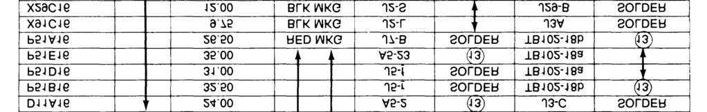

174 TM Change 8 Figure Set Special Relay Assembly (Class 1, Mode I) Sets, Wiring Harness (Sheet 3 of 5)

 Sets,")
")
175 Figure Set Special Relay Assembly (Class 1, Mode I) Sets, Wiring Harness (Sheet 4 of 5) Change
176 ME /5-27(5) 5-54 Figure Set Special Relay Assembly (Class 1, Mode I) Sets, Wiring Harness (Sheet 5 of 5)
177
178
179 TM Figure Set Special Relay Assembly (Class 1, Mode II) Sets, Wiring Harness (Sheet 2 of 5) Change
180 TM Change 8 Figure Set Special Relay Assembly (Class 1, Mode II) Sets, Wiring Harness (Sheet 3 of 5)
181 Figure Set Special Relay Assembly (Class 1, Mode II) Sets, Wiring Harness (Sheet 4 of 5) Change


182 5-60 Figure Set Special Relay Assembly (Class 1, Mode II) Sets, Wiring Harness (Sheet 5 of 5)
183 Figure Load Measuring Unit Interconnecting, Wiring Harness 5-61/(5-62 blank)
184
185
186


187 ME /5-30(2) -65 Figure Engine Accessories, Wiring Harness (Sheet 2 of 3)
188 -66 ME /5-30(3) Figure Engine Accessories, Wiring Harness (Sheet 3 of 3)

189 Figure Paralleling Cable Assembly 5-67
190 5-68 Figure Fuel Burning Winterization Kit, Wiring Harness
191 ME /5-33 Figure Fuel Burning Winterization Control, Wiring Harness 5-69
192 5-70 ME /5-34(1) Figure Electric Winterization Kit, Wiring Harness (Sheet 1 of 2)
193 ME /5-34(2) 5-71 Figure Electric Winterization Kit, Wiring Harness (Sheet 2 of 2)

 ME")
194 Figure Electric Heater Control Box, Wiring Harness (Sheet 1 of 2) ME /5-35(1) Cl 5-72 Change 1
195 ME /5-35(2) Figure Electric Heater Control Box, Wiring Harness (Sheet 2 of 2) 5-73/(5-74 blank)
196
197
198
199 Figure Load Bank, Wiring Harness (Sheet 2 of 3) Change


200 5-78 Change 4 Figure Load Bank, Wiring Harness (Sheet 3 of 3)
201 5-79 Figure Load Bank Capacitor (Sheet 1 of 2)
202 5-80 Figure Load Bank Capacitor (Sheet 2 of 2)
203 Figure Load Bank Control Panel, Wiring Harness (Sheet 1 of 2) 5-81

204 5-82 Figure Load Bank Control Panel, Wiring Harness (Sheet 2 of 2)
205 Figure Special Purpose Cables Assembly for Generator Set to Load Bank Main Power Cable Change
206 5-84 Figure RFI Capacitors, Wiring Harness
207 CHAPTER 6 LOAD CONNECTION GROUP REPAIR INSTRUCTIONS Section I. INTRODUCTION 6-1. Scope. This chapter contains repair instructions for the main load contactor and current transformer of the load connection group Load Connection Group Description. a. The load connection group consists of the main load contactor, load terminal board assembly, current transformer assembly, and reconnection board. b. The main load contactor connects the main generator output to the load. The contactor closes when the load contactor switch (S-3) (refer to Operatar and Organizational Maintenance Manual) is placed in the on position momentarily. c. The load terminal board provides a means of connection to the generator set load. The contactor connects the generator output to the load through the load terminal board. d. The output cables of the generator pass through the cores of the current transformers. When the generator is connected to a load, a proportional current is induced in the current transformer secondary. This secondary current is used by the excitation system as a current boost during a short circuit and cross current compensation during parallel operation The current transformer secondary is also used to operate the ammeter and wattmeter circuits in the control panel and it is used in the load measuring unit circuit. e. The reconnection board permits reconnection of the generator phase windings to give optional output voltages. Both ends of each coil of each phase winding run from the generator to a stud on the reconnection board. A changeover board, with copper bus bars, is mounted so that the studs contact the bus bars. The bus bars are so designed that by moving the changeover board to one of two positions, the generator phase coils may be connected in series or parallel for 120/208 volt or 240/416 volt operation f. Refer to the Operator and Organizational Maintenanance Manual for maintenance instruction procedures covering the load terminal board and reconnection board. Section II. MAIN LOAD CONTACTOR 6-3. Removal and Disassembly. a. Removal. Refer to Operator and Organizational Maintenance Manual and remove the main load contactor. b. Disassembly. See figure 6-1 or figure 6-1 D (used on Serial Numbers FZ on, for 50/60 Hz and Serial Numbers FZ on, for 400 Hz) and disassemble the main load contactor as illustrated Cleaning, Inspection, and Testing. a. Cleaning. Clean all components with cloth dampened in cleaning solvent, Federal Specification P-D-680. b. Inspection. Refer to Operator and Organizational Maintenance Manual. c. Testing. Refer to Operator and Organizational Maintenance Manual Repair. a. Replace contactor actuator coil if defective. b. Replace contacts in contactor if badly pitted or burned. When one contact is damaged, all contacts must be replaced. c. Repair damaged threads with a die or by filing with a fine mill file Reassembly and Installation. a. Reassembly. See figure 6-1 and reassemble the-main load contactor observing the following: (1) After assembly of the operator assembly (23) refer to figure 6-1A and perform the following adjustment procedures: Change 3 6-1
208 Plate Plate Screw Washer Washer Cover Screw Washer Screw Washer Washer Cover assy Contactor assy Gasket Gasket ME /6-1(1) Cl 6-2 Change 1 Figure 6-1. Main Load Contactor (Sheet 1 of 3)

 Cl Figure 6-1.")
209 16. Screw 17. Washer 18. Washer 19. Chamber 20. Gasket 21. Nut 22. Washer 23. Operator assy. 24. Ring, retaining 25. Bushing, locating 26. Spring 27. Shim 28. Shim 29. Shim 30. Bridge assy. 31. Operator 32. Bushing, adjusting 33. Nut 34. Washer 35. Washer 36. Screw 37. Washer 38. Base assy. 39. Nut 40. Washer 41. Washer 42. Contact assy. 43. Arc chute 44. Grommet 45. Spacer 46. Base ME /6-1(2) Cl Figure 6-1. Main Load Contactor (Sheet 2 of 3) Change 1 6-3
210 47. Screw 48. Screw 49. Washer 50. Washer 51. Clamp 52. Connector aux. contact assy. 53. Connector and wire assy Connector 62. Aux. contact assy 63. Au. contact assy 64. Screw 65. Washer 66. Switch 67. Screw 68. Washer 69. Washer Bracket Actuator assy Nut Washer Terminal Rod Spring Operator assy Nut Washer Washer Screw Bracket Nut Washer Operator aux. Core and rod Screw Washer Washer End Plate Washer Coil Core and frame 6-4 Change 1 Figure 6-1. Main Load Contactor (Sheet 3 of 3) ME /6-1(3) C1
211 (a) Check each individual contact at its edge (insert A) with a force gauge. Preload should be between 1-1/2-2 1/2 lbs. This can be attained by adding or removing shim (see chart, figure 6-1A). (b) Preload is checked by the initial breakaway of the E ring at point B, figure 6-1A. Preload should be between 1-1/2 to 2-1/2 lbs. This can be obtained by adding or removing shim (See chart, figure 6-1A). (2) After assembly of the actuator assembly (64, figure 6-l), refer to figure 6-lB and perform the following adjustment procedures (a) Leave four screws (1) loose. (b) Clamp assembly at points A and B to assure no-air gap at points C and D. (c) With assembly clamped, tighten four screws (1). (d) Remove clamp. (e) Insert feeler gauge ( in.) into movable core gap and adjust guide screws (2) evenly until gauge is snug throughout the parimeter. (f) Secure after adjustment by tightening two nuts (3). (3) Contactor adjustment. (a) Contact overtravel. Refer to figure 6-lC and proceed as follows: (1) Attach indicator lamp on ohmeter to terminal A1-A2 & C1-C2. (2) Insert gauge into movable core cap (A). (3) Apply 24 VDC to coil. (4) Adjust carrier bushings at point (B) until continuity is made on A1-A2 & C1-C2. (5) Secure by tightening nuts (l). (6) Recheck continuity at No continuity at readjust if necessary. (b) Economizing switch. Refer to figure 6-lC and proceed as follows: (1) Adjust switch bracket (3) to transfer switch. Check that white button is fully depressed and allow approximately clearance between white button and tap operator (point C). Secure screws on bracket. gap (A). (2) Insert gauge into movable core (3) Apply 24 VDC to coil. (4) Adjust lower tap (D) by bending to transfer switch. (5) Recheck gauge transfer gauge no transfer Readjust if necessary (c) Auxiliary contacts. Refer to figure 6-lC and proceed as follows: (1) Before adjustment, set lift comb item (5) so that the deflector on the guide leaf springs (6) are near equal in energized and de-energized position. Secure by tightening nuts (4). (2) Normally closed. Insert guage between guide rod head and operator plate, (point D 2 places). Adjust stationary contacts to just touch the movable contact (use indicator light) - recheck with gauge at point (D). No continuity. Readjust if necessary. (3) Normally Open. Same as normally closed except shims are inserted into movable core gap (point A). Change 1 6-4A


212 Figure 6-lA Operator Assembly- Main Contact Adjust Procedure Figure 6-1B. Actuator Assembly Adjustment Procedure 6-4B Change 1
213 Figure 6-1C. Contactor Adjustment Change 8 6-4C
214 1. Identification plate 2. Wiring diagram plate 3. Screw 4. Lock washer 5. Flat washer 6. Shield 7. Contactor subassy 8. Screw Lock washer Screw Lock washer Flat washer Screw Lock washer Cover Switch-Connector assy Aux switch Aux switch Connector Gasket 6-4D Change 8 Figure 6-lD. Main Load Contactor (Sheet l of 3)

215 21. Locking spacer 22. Lock washer 23. Flat washer 24. Chamber 25. Gasket 26. Nut 27. Lock washer 28. Flat washer 29. Base assy 30. Screw 31. Lock washer 32. Flat washer 33. Flat washer 34. Nut 35. Bus bar 36. Insert 37. Base 38. Gasket 39. Nut 40. Lock washer 41. Flat washer 42. Spacer 43. Bushing 44. Bushing 45. Bridge assy 46. Housing 47. Bridge 48. Spring 49. Bushing 50. Arc chute 51. Screw 52. Lock washer 53. Metallic washer 54. Insulation 55. Detent Figure 6-lD. Main Load Contactor (Sheet 2 of 3) Change 3 6-4E
216 F Change 8 Operator Operator Screw Lock washer Screw Lock washer Nut Spring Solenoid subassy Moveable core-rod assy Lock washer Nut 68. Rod 69. Core assy 70. Stud 71. Operator 72. Frame-core assy 73. Frame assy 74. Screw 75. Flat washer 76. Frame 77. Screw 78. Lock washer 79. Flat washer Figure 6-1D. Main Load Contactor (Sheet 3 of 3) 80. Frame 81. Frame 82. Screw 83. Flat washer 84. Micro switch assy 85. Screw 86. Lock washer 87. Flat washer 88. Switch 89. Bracket 90. Plate 91. Coil
217 Section III. CURRENT TRANSFORMER 6-7. On Equipment Test Removal and Disassembly. a. The following resistance readings should be a. Removal precent for good current transformers. Use a Simpson 260 or equivalent meter, (properly zeroed) with (1) Remove and tag the generator output leads the R x 1 scale selected for making the measure- and pass them through the associated current transments. formers freeing the current transformer assembly for removal. (fig. 6-2) b. Current transformer secondary resistance readng. (fig. 6-2) Percent of Rated Load Meter LMU Cross Current Compensation CT1... CT2... CT3... CT4... CT5... CT6... CT7... (2) Remove the generator harness wiring from terminal block TB16, identifying each lead with 2.5 ohms the terminal block post number from which it was same as CTl removed. same as CTl (3) Remove the current transformer assem- 0.2 ohms pins 1 to 3, 0.1 bly (7, fig. 6-3) by removing hardware items 3, ohm center pin to 1 and 4 and 5. center pin to same as CT4 same as CT4 0.5 ohms pins l and 2 3 b. Disassembly. See figure 6-4 and disassemble the current transformer as illustrated. Figure 6-2. Routing Main Generator Leads Through Current Transformers Change 1 6-5
218 6-6 Change l Figure 6-3. Current Transformer Assembly and Load Connecting Group Mounting Brackets

219 Figure 6-4. Current Transformer Assembly Change 1 6-7
220 6-9. Cleaning, Inspection, and Testing. a. Cleaning. Clean all components with a cloth dampened in cleaning solvent, Federal Specification P-D-680. b. Inspection. Refer to Operator and Organizational Maintenance Manual. c. Testing. (1) To test CTl, CT2, and CT3 on either Mode I or Mode II sets, proceed as follows: (a) Wrap 10 turns of a conductor around the coils of cm. (b) Apply an ac current of 10 amperes to the conductor. (c) The current measured at terminals Al and A2 must be 360 ma. (d) Repeat steps (a) through (c) on CT2 and CT3. Measure CT2 at terminals B1 and B2; measure CT3 at terminals Cl and C2. (2) To test CT4, CT5, and CT6 on either Mode I or Mode II sets, proceed as follows (a) Apply 20.7 volts (rms) 60 Hz across terminals l and 3. (b) Voltage between terminals 1 and 2 shall measure ± 1 percent Vac. 36 ma. (c) Excitation current shall be less than (d) Apply 50 amperes 60 Hz through 1 primary turn. Secondary current should be 180 ma ± 1% at terminals 1-3. (3) To test CT7 on Mode II sets, proceed a follows: (a) Apply 15 volts (rms) 400 Hz across, terminals 1 and 2. (b) The excitation current shall be less than 45 ma (rms). (c) Apply 50 amperes 400 Hz through 1 primary turn. Secondary current should be 250 ma ± 1%. (4) To test CT7 on Mode I sets, proceed as follows: (a) Apply 15 volts (rms) 60 lb across terminals 1 and 2. (b) Excitation current shall be less than 60 ma (rms). (c) Apply 50 amperes 60 Hz through 1 primary turn. Secondary current should be 250 ma ± 1% a. b. c Repair. Replace defective current transformers. Replace worn grommets. Replace all gaskets with new ones. Reassembly and Installation. a. Reassembly See figure 6-4 and reassemble the current transformer assembly. b. Installation. See paragraph 6-8 and install the current transformer assembly. 6-8 Change 1
221 CHAPTER7 ELECTRO-HYDRAULIC GOVERNING SYSTEM (CLASS I, PRECISE SETS ONLY) 7-1. General a. The electro-hydraulic governing system is a speed (frequency) sensing stem used to maintain prime mover speed constant and therefore generator output frequency, during periods of unchanging load and when load additions or deletions occur. b. The system consists of a control unit, load measuring unit and hydraulic throttle actuating unit. c. The control unit inputs are the generator output voltage, and a dc voltage ( Vdc) proportional to the generator load, supplied by the load measuring unit. The generator voltage input is applied to a frequency sensing network and reference voltage network, The differ ential output of these two networks determines the control current of two magnetic amplifiers whose outputs drive separate coils of the hydraulic actuators pilot valve. The actuator pilot valve positions the actuator power piston which is connected to the input arm of the fuel injection pump. The actuators hydraulic system is comprised of a reservoir, engine driven pump ( psi, 2 gpm), cooler and filter. d. Any deviation of engine speed, reflected as a change in frequency at the input of the governor, produces a change in the magnitude and direction of magnetic amplifier control field current. This change in ccntrol field current will increase the strength of one coil of the pilot valve while decreasing the strength of the other, The resultant difference repositions the pilot valve in turn repositioning the power piston which changes the output of the fuel injection pump, changing engine speed and consequently restoring generator frequency to its nominal value. e. The load measuring units (LMU) input to the governor control provides for automatic load sharing when two or more sets are operated in parallel. Each set is equipped with an LMU. f. If the load added to the system is not equally divided, the LMU inputs to their respective governors will differ. The resulting difference acting through additional windings of each sets governor (which are all connected in parallel) will reposition each sets actuator power piston such that fuel flow in the more heavily loaded set is decreased while that of the lightly loaded set is increased. Since the power input of each prime mover has been readjusted, equal division of true power (Kw) occurs with no deviation in frequency of any set Malfunction. The following procedures are to be performed in the generator set unless otherwise specified. a. If the FL - NL or NL - FL transient exceeds 1-1/2 percent of rated speed and/or does not re - establish stable engine operating conditions within one second, realign the control unit in accordance with paragraph 7-8. Also follow this procedure if the engine speed hunts. If the set cannot be stabilized, check sockets A and B of plug P-21 (refer to Operator and Organizational Maintenance Manual) for 24 Vdc (A is positive). b. If the engine speed increases to above nominal operating speed, check sockets A and B of P-17 for 120 Vat. If it is missing, troubleshoot the generator set wiring. (Refer to Operator and Organizational Maintenance Manual). If it is present, check the resistance of the frequency adjusting circuit consisting of R4 (250 ohms) rheostat R1 frequency adjust (500 ohms) and R5 (250 ohms) fixed resistor. Refer to Operator and Organizational Maintenance Manual. Measure the total circuit resistance across N and T of harness plug P17. The circuit resistance should be 1000 ohms (5 percent tolerance). After testing for correct total resistance, test the operation of the frequency adjust rheostat by connecting an ohmmeter across pins M and T and revolving the frequency adjust rheostat through its entire travel. The resistance should vary from 750 ohms to 250 ohms. Repeat this procedure using the ohmmeter across pins M and N of the harness plug. If the problem persists, check sockets A and B of plug P-21 for 24 Vdc (A is positive). c, If the engine speed remains below the nominal operating speed, adjust R1. If there is no improvement, check the resistance of the frequency adjust circuit. Disconnect P-17 and check the resistance of the frequency adjust circuit consisting of R4 (250 ohms) fixed resistor, R1 frequency adjust rheostat (500 ohms) and R5 (250 ohms, 5 percent) fixed resistor. Refer to Operator and Organizational Maintenance Manual. Measure the total circuit resistance across N and T of harness plug P17. The circuit resistance should be 1000 ohms (5 percent tolerance). After testing for correct total resistance, test the operation of the frequency adjust potentiometer by connecting an ohmmeter across pins M and T and revolving the frequency adjust potentiometer through its entire travel. The resistance should vary from 750 ohms to 250 ohms. Repeat this procedure using the ohmmeter across pins M and N of the harness plug. Disconnect actuator electrical connector before making this measurement. Push actuator piston all the way down and adjust engine speed with manual throttle. If this value resistance is measured, check sockets A and B at plug P-21 for 24 Vdc (A is positive). d. If the set is operating at a constant load and voltage and during an eight-hour period the change in ambient temperature does not exceed 60 F, the set frequency should not drift beyond 1/2 of one percent of rated frequency. The above requirement assumes that the set temperatures were stabilized 7-1
222 at the initial and final ambient temperatures. NOTE If the drift in paragraph d is excessive, realign the control unit following the procedure outlined in paragraph 7-8. e. At constant ambient temperature, constant load, constant voltage and constant barometric pressure, the set frequency should remain within a bandwidth of 1 percent of rated frequency for a period of 4 hours. If this bandwidth has been exceeded, realign the control unit in accordance with paragraph 7-8. f. If the preceding solutions to the specific problem do not resolve the problems, replace and repair the control unit, actuator (para 13-3 thru 13-8) or load measuring unit (para 8-15 thru 8-19) as required Removal. Refer to figure 7-1 and remove in the order of sequence numbers Disassembly and Repair a. Disassemble electric governor control unit, if required, as illustrated in figure 7-2. NOTE Disassembly and repair of electric governor control unit at the field level is restricted to removal of the cover, connectors, potentiometers and test jacks. further disassembly requires unpotting and the following disassembly can be performed by depot maintenance personnel only. b. Remove cover and components installed on cover in the order of sequence numbers (1 thru 15). NOTE Tag and unsolder wires for the components on the cover. (1) Replace defective test jacks, potentiometers or connectors. (2) Repair procedures for individual wires of a wiring harness are covered in the Operator and Organizational Maintenance Manual. c. Remove six screws and lockwashers from cover of control unit. Lift cover slightly and set at a slight angle to keep the connectors and potentiometers out of the potting compound. d. Place the complete unit in a trolled oven, large enough to allow completely around the unit. 7-2 temperature conair to circulate CAUTION The melting temperature of the potting compound is 165 F. The flash point is 515 F. Do not unpot by placing unit on a hot plate type surface or by using an open flame. e. Set the oven temperature at 180 F to 185 F and allow the unit to soak until the potting compound is melted. The normal soak period at this temperature is 11 to 12 hours. WARNING Use care when handling the hot potting compound. It can cause severe injury to personnel. f. Using heavy gloves and wearing safety glasses, remove the printed circuit board from the melted putting compound. Lift the board s1owly, allowing the potting compound to drain off the components. g. Set the printed circuit board with transformers on the bottom on a drain board and allow it to cool to room temperature. h. Remove screw (4) and lockwashers (5) which attach connectors (P1, J3, P5, P2) to cover. i. Tag wiring and remove harness (6). j. Disassemble remaining components mounted on cover in accordance with index numbers 7 through Cleaning and Inspection. a. Clean all parts with a cloth dampened in cleaning solvent Federal Specification P-D-680 and dry thoroughly. b. Inspect for cracks, breaks, damaged connectors, damaged terminals, defective wiring, and defective components. Check potentiometer for continuity, resistance, and wiring for open insulation Tests and Repair. a. Perform test as outlined in figures 7-3 thru NOTE Mount circuit card as shown in figure 7-11 prior to test. b. Resistance Test (50/60 Hz). Refer to Table 7-1 and perform resistance test. c. See figure 1-4 and 1-5 for schematic diagrams. d. See table 7-2 for values of individual components. When measuring individual components, disconnect at least one lead to prevent feedback readings.
223 Figure 7-1. Electric Governor Control Unit Removal Change l 7-3
224 7-4 Change 1 Figure 7-2. Electric Governor Control Unit
225 Table 7-1. Resistance Test (50/60 Hz) P1 Potentiometer Nominal Allowance resistance Connection Position Resistance range (ohms) T-N (T +) M-N (M +) F-N (F +) E-G (E +) R-G (R+) F-G (F +) J-H (J +) T-P (T +) U-S (U+ ) (M +) R18CCW (F+) R16CCW (F+) Rl5CCW LESS THAN 0.2 OHMS (T+) R14CCW USING M1, MEASURE RESISTANCE OF EACH PIN (ALL CONNECTORS) AND EACH TEST POINT TO GOVERNOR CONTAINER. RESISTANCE SHOULD BE INFINITY ON 100,000 OHM SCALE REPEAT FOR REVERSE POLARITY RESISTANCE SHOULD BE INFINITY ON 100,000 OHM SCALE. MAGNETIC AMPLIFIER BIAS TEST TURN R1l, R12, R14, R15, R16, R18 FULL CW. CONNECT GOVERNOR CONTROL UNIT TO TEST EQUIPMENT AS SHOWN. ALMOST R11 AND Rl2 FOR BALANCED READING OF 450 MA ON M2 AND M3. TURN R12 FULL CW. M2 AND M3 SHALL READ MA, AND BE BALANCED WITHIN 50 MA. TURN R12 FULL CCW. M2 AND M3 SHALL READ MA, AND BE BALANCED WITHIN 50 MA. READJUST Rll AND Rl2 FOR BALANCED READING OF 450 MA ON M2 AND M3. LOCK Rll AND Rl2 FOR REMAINDER OF TEST. ME /7-3 Figure 7-3. Electric Governor Control Unit, Magnetic Amplifier Bias Test (50/60 Hz) Change 1 7-5


226 REF DES QUANTITY TEST EQUIPMENT FREQUENCY SENSING CHECK (HIGH AND LOW FREQUENCY) CONNECT GOVERNOR CONTROL UNIT TO TEST EQUIPMENT AS SHOWN TURN Ra SO THE Resistance BETWEEN P1-M AND Pl-T IS 250 OHMS. REDUCE THE FREQUENCY OF THE AP- PLIED 120 ± 2 VOLT SUPPLY UNTIL M2 AND M3 BALANCE. THE FREQUENCY SHALL BE Hz. TURN Ra SO THE RESISTANCE BETWEEN P1-M AND P1-N IS 250 OHMS. INCREASE THE FREQUENCY OF THE AP- PLIED 120 ± 2 VOLT SUPPLY UNTIL M2 AND M3 BALANCE. THE FREQUENCY SHALL BE Hz. DESCRIPTION Ra Rb, RC M2., M3 Vl 1 POTENTIOMETER, 10 TURN, 500 OHM, 5 WATT 2 RESISTOR, FIXED, 250 OHM, 5 WATT 2 MILLIAMMETER, DC, MA DC POWER SOURCE AC POWER SOURCE ME /7-4 C1 Figure 7-4. Electric Governor Control Unit, Frequency Sensing Check (High and Low Frequency) (50/60 Hz) e. Magnetic Amplifier Bias Test (50/60 Hz). Refer to figure 7-3 and perform the magnetic amplifier bias test. f. Frequency Sensing Check, High and Low Frquency (50/60 Hz). Refer to figure 7-4 and perform the frequency sensing check. g. Rectifier Bridge, CR7 thru CR30 and Feedback Winding Test (50/60 Hz). Refer to figure 7-5 and perform the rectifier bridge and feedback winding test. h. Parallel Winding Test (50/60 Hz). Refer to figure 7-6 and perform the parallel winding test. i. Resistance Test (400 Hz). Refer to Table 7-3 and perform resistance test. j. Magnetic Amplifier Bias Test (400 Hz). Refer to figure 7-7 and perform the magnetic amplifier bias test. k. Frequency Sensing Check, High and Low Frequency (400 Hz). Refer to figure 7-8 and perform the frequency sensing check. L Rectifier Bridge, CR7 thru CRl0 and Feedback Winding Test (400 Hz). Refer to figure Change 1 and perform the rectifier bridge and feedback winding test. m. Parallel Winding Test (400 Hz). Refer to figure 7-10 and perform the parallel winding test. n. Replace any component found to be defective during tests. o. For wiring harness repairs, refer to Operator and organizational Maintenance Manual. p. If wiring harness has sustained extensive damage, refer to Chapter 5 for wiring harness rebuilding procedures Assembly. a. See figure 7-12 and assemble printed circuit board. If any connections are opened or bared for test purposes, or if any defective components are replaced, the effected area and components must be coated with polyurethane resin to prevent oxidation or other corrosion. The coating must be of a minimum thickness of inches and air bubble entry into the applied polyurethane must be controlled so that the legibility of component coding and identification is not impaired. The polyurethane resin to be utilized will correspond to MIL-I-46058,
227 Table 7-2. Electric Governor Control Unit Component Values 50/60 Hz Unit 400 Hz Unit Component (ohms) (ohms) Remarks R1, R1A, R % tolerance Rll R4, R8, R % tolerance R R2, R % tolerance R12, R18 10,000 10, % tolerance R16 25,000 25, % tolerance R14, R20 3,000 3, % tolerance Parallel winding Less than 1.0 Less than 1.0 Check for open (nominal ) (nominal) Feedback winding Less than 1.0 Less than 1.0 Check for open (nominal) (nominal) Frequency control Less than 1.0 Less than 1.0 Check for open winding (nominal) (nominal) Bias control winding Less than 1.0 Less than 1.0 Check for open (nominal) (nominal) Grade S, Type PUR. b. See figure 7-2 and reassemble control unit components. c. Reconnect cover to printed circuit board with wiring harness. d. Place the container in a temperature controlled oven. Set oven temperature at 180 to 185 F and allow container to soak 11 to 12 hours or until potting compound is completely melted. e. Prior to installing the printed circuit board, remove the container from the oven and make sure that insulation paper is positioned next to the container shell. f. Using heavy gloves, and safety glasses slowly lower the printed circuit board into the potting compound, WARNING Use care not to splash hot potting compound om operating personnel. It can cause severe injury. g. Position the printed circuit board and allow compound to cool. h. When compound has cooled and is substantiality solid, install top cover and hardware Adjustment. See figure 7-13 for location of adjustment and controls and adjust electric governor according to the following procedures a. Single Set Adjustment Procedures (1) With engine not operating, set frequency adjust control (on control panel), R11, R14, R16, and R18 to midpoint by turning full each way and approximating center. Set RI 5 full counterclockwise and R12 approximately 1/4 clockwise. (2) Start engine. Refer to Operator and Organizational Maintenance Manual for operating instructions. If engine hunts, perform following adjustments to stabilize operation (a) If hunt is of high frequency and small amplitude; adjust R12 clockwise and/or R16 counterclockwise. (b) If hunt is of low frequency and long amplitude; adjust Rl8 countercloclwise. If operation does not stabilize, turn R16 clockwise. It maybe necessary to adjust R12 counterclockwise in conjunction with R18 and R16 adjustments to stabilize operation. Change 5 7-7
![REF DES QUANTITY TEST EQUIPMENT DESCRIPTION Rd 1 RESISTOR, FIXED, 5000 OHMS, 1 WATT Rf, Rg 2 RESISTOR ] FIXED, B2 OHM, 10 WATT Rh, Ri 2 RESISTOR FIXED, 15 OHMS, 5 WATT Rj 1 RESISTOR, FIXED, 25 OHMS,](/docs-images/94/119610197/images/228-1.jpg "5 WATT M2, M3 2 MILLIAMMETER, DC, 0-1000 MA M4 1 MILLIAMMETER, DC, ZERO CENTER, 10-0-10 MA 1 SWITCH, ROTARY, 3 POSITION, 1 POLE, 1 AMP 1 DC POWER SOURCE 1 AC POWER SOURCE 1 AUTOTRANSFORMER 2:1 RATIO")
 (3) Once the set has been stabilized, connect a 0-10 volt range dc voltmeter (high impedance type -2000 ohms per")
228 REF DES QUANTITY TEST EQUIPMENT DESCRIPTION Rd 1 RESISTOR, FIXED, 5000 OHMS, 1 WATT Rf, Rg 2 RESISTOR ] FIXED, B2 OHM, 10 WATT Rh, Ri 2 RESISTOR FIXED, 15 OHMS, 5 WATT Rj 1 RESISTOR, FIXED, 25 OHMS, 5 WATT M2, M3 2 MILLIAMMETER, DC, MA M4 1 MILLIAMMETER, DC, ZERO CENTER, MA 1 SWITCH, ROTARY, 3 POSITION, 1 POLE, 1 AMP 1 DC POWER SOURCE 1 AC POWER SOURCE 1 AUTOTRANSFORMER 2:1 RATIO ME /7-5 Figure 7-5. Electric Governor Control Unit, Rectifier Bridge and Feedback Winding Test (50/60 Hz) (3) Once the set has been stabilized, connect a 0-10 volt range dc voltmeter (high impedance type ohms per volt or more) across test points 3 and 4 with the positive lead at test point 4. Adjust FREQUENCY ADJUST control to obtain operating frequency (400 W, or 60 Hz), and then adjust R14 until volt e across test points 3 and 4 is zero volts, with no load on generator. (4) Connect dc voltmeter across tests points 1 and 2 with positive lead at test point 1. Adjust R11 and the frequency adjust control until the dc voltmeter reads zero volts at nominal frequency. Repeat the adjustment until the voltage across test points 3 and 4 and across 1 and 2 is zero volts, and the set frequency is 50 Hz, 60 Hz or 400 Hz with no load on the engine. If test points 1 and 2 cannot be zeroed, they must be reduced to a minimum. (5) Adjust RI 2 until a reading of approximately 4.5 volts is obtained across test points A and B, with no load on generator. If this voltage is too low, response will be sluggish and if it is too high, a rapid oscillation may occur. Normal range is 3 to 6 volts. (6) Adjust R18 clockwise as far as possible, and R16 counterclockwise as far as possible without causing oscillation, NOTE Increasing the load measurement gain R15 (turing in a clockwise direction) will improve transient performance; therefore it should be adjusted as high as possible. Transient performance must be checked using a frequency recorder. 7-8 Change 1

 (7) The adjustment of R18 and R16 are interdependent.")

229 PARALLEL WINDING TEST CONNECT GOVERNOR CONTROL UNIT TO TEST EQUIPMENT AS SHOWN. M2 SHALL READ MA. M3 SHALL READ MA. REVERSE POLARITY OF CONNECT- IONS TO PINS J1-E AND J1-G. M2 SHALL READ MA. M3 SHALL READ MA. REF DES Re M2, M3 Vl V2 QUANTITY TEST EQUIPMENT DESCRIPTION 1 RESISTOR, FIXED, 50,000 OHMS, 10 WATT 2 MILLIAMMETER, DC, MA 1 DC POWER SOURCE 1 DC POWER SOURCE 1 AC POWER SOURCE ME /7-6 Figure 7-6. Electric Governor Control Unit Parallel Winding Test (50/60 Hz) (7) The adjustment of R18 and R16 are interdependent. For any position of R18 there is an optimum position for R16. Therefore, to improve transient performance, increase the frequent y gain by turning R18 clokwise. If hunt develops, readjust R16 for stability. If no hunt develops, apply and reject load on the generator set to check for stability under transient conditions. Assuming that no hunt develops for an increase in frequency gain, (R18 turned clockwise) or that hunt can be removed by readjustment of R16, again increase frequency gain. by turning R18 clockwise and note the transient performance. Finally a position may be reached where no readjustment of R16 can stabilize for the high frequency gain of R18. Then reduce the frequency gain to the stable region and optimize stability and performance with R16. The frequency gain should be reduced to a point where the system is not on the edge of instability for long-term stable operation. (8) Transient performance improves as the frequency gain R18 is increased and the feedback gain R16 is a minimum for that particular position of frequency gain adjustment. If R16 is adjusted too far counterclockwise, there will be insufficient feedback to stabilize the operation at steady state. If a slow oscillation occurs, turn R16 clockwise until stability is reached. This is the optimum setting for the level of frequency gain. (9) If R16 is turned far clockwise, a very fast oscillation may occur. Turn R16 counterclockwise to the optimum point of stability. b. Parallel Operation (Class 1 sets) (1) Adjust in accordance with paragraph (2) If the sets will not divide load, or if they oscillate (successively interchange load) on the first attempt to parallel, check the polarity across pin A and B of the parallel receptacle on both sets and verify, that the input circuits to pin C and D are correct and that the voltages are as specified Equipment Test If the electric governor control has been renewed or repaired, refer to Chapter 16, Section II and conduct the following tests. a. Frequency and voltage regulation, stability and transient response test, short term. (para 16-15) b. Frequency adjustment range test (para 16-16) Change 1 7-9
230 Table 7-3. Resistance Test (400 Hz) P1 Potentiometer Nominal Connection Position Resistance Allowable resistance range (ohms) T-N (T +) M-N (M +) (M +) R18CCW F-N (F + ) (F +) R16CCW (F +) R15CCW E-G (E +) R-G (R + ) F-G (F +) J-H (J+) LESS THAN 0.2 OHMS T-P (T+) (T +) R14CCW U-S (U +) USING Ml, MEASURE RESISTANCE OF EACH PIN (ALL CONNECTORS) AND EACH TEST POINT TO GOVERNOR CONTAINER. RESISTANCE SHOULD BE INFINITY ON 100,000 OHM SCALE. REPEAT FOR REVERSE POLARITY. RESISTANCE SHOULD BE INFINITY ON 100,000 OHM SCALE 7-10 Change 5

231 MAGNETIC AMPLIFIER BIAS TEST. TURN Rll, R12, R14, R15, R16, R18 FULL CW. CONNECT GOVERNOR CONTROL UNIT TO TEST EQUIPMENT AS SHOWN. ADJUST Rll AND Rl2 FOR BAL- ANCED READING OF 450 MA ON M2 AND M3. TURN R12 FULL CW. M2 AND M3 SHALL READ MA, AND BE BALANCED WITHIN 50 MA. TURN R12 FULL CCW. M2 AND M3 SHALL READ MA, AND BE BALANCED WITHIN 50 MA. READJUST Ml AND R12 FOR BAL- ANCED READING OF 450 MA ON M2 AND M3 AND LOCK Rll AND Rl2 FOR REMAINDER OF TEST. TEST EQUIPMENT REF DES QUANTITY DESCRIPTION M2, M3 2 MILLIAMMETER, DC, MA V1 1 DC POWER SOURCE 1 AC POWER SOURCE ME /7-7 Figure 7-7. Electric Governor Control Unit, Magnetic Amplifier Bias Test (400 Hz) 7-11

232 FREQUENCY SENSING CHECK (HIGH AND LOW FREQUENCY) CONNECT GOVERNOR CONTROL UNIT TO TEST EQUIPMENT AS SHOWN TURN Ra SO THE RESISTANCE BETWEEN P1-M AND P1-T IS 250 OHMS. REDUCE THE FREQUENCY OF THE AP- PLIED 120 ± 2 VOLT SUPPLY UNTIL M2 AND M3 BALANCE. THE FREQUENCY SHALL BE Hz. TURN Ra SO THE RESISTANCE BETWEEN P1-M AND P1-N IS 250 OHMS. INCREASE THE FREQUENCY OF THE APPLIED 120 ± 2 VOLT SUPPLY UNTIL M2 AND M3 BALANCE. THE FREQUENCY SHALL BE Hz. TEST EQUIPMENT REF DES Ra Rb, RC M2, M3 QUANTITY DESCRIPTION 1 POTENTIOMETER, 10 TURN, 500 OHMS, 5 WATT 2 RESISTOR, FIXED, 250 OHMS, 5 WATT 2 MILLIAMMETER, DC, MA 1 DC POWER SOURCE 1 AC POWER SOURCE Figure 7-8. ME /7-8 Electric Governor Control Unit, Frequency Sensing Check (400 Hz) 7-12
233 REF DES Ra Rb, Rc Rd Re Rf, Rg Rh, Ri Rj Ml M2, M3 M4 QUANTITY TEST EQUIPMENT DESCRIPTI0N POTENTIOMETER, 10 TURN, 500 OHMS, 5 WATT RESISTOR, FIXED, 250 OHMS, 5 WATT RESISTOR, FIXED 5000 OHMS, 1 WATT RESISTOR, FIXED, 50,000 OHMS, 10 WATT RESISTOR, FIXED, 32 OHMS, 10 WATT RESISTOR, FIXED, 15 OHMS, 5 WATT RESISTOR, FIXED, 25 OHMS, 5 WATT OHMMETER, 100,000 OHMS SCALE MILLIAMMETER, DC, MA MILLIAMMETER, DC, ZERO CENTER, MA SWITCH, ROTARY, 3 POSITION, 1 POLE, 1 AMP GOVERNOR ACTUATOR, P/N E5390 DC POWER SOURCE DC POWER SOURCE AC POWER SOURCE AUTOTRANSFORMER 2:1 RATIO ME /7-9 Figure 7-9. Electric Governor Control Unit, Rectifier Bridge and Feedback Winding Test (400 Hz) 7-13

234 PARALLEL WINDNG TEST. CONNECT GOVENOR CONTROL UNIT TO TEST EQUIPMENT AS SHOWN M2 SHALL READ MA. M3 SHALL READ MA. REVERSE POLARITY OF CONNECT- IONS TO PINS J1-E AND J1-G. M2 SHALL READ MA. M3 SHALL READ MA. TEST EQUIPMENT REF DES QUANTITY DESCRIPTION Re 1 RESISTOR, FIXED, 50,000 OHMS, 10 WATT M2, M3 2 MILLIAMMETER, DC, MA V1 1 DC POWER SOURCE V2 1 DC POWER SOURCE 1 AC POWER SOURCE ME /7-10 Figure Electric Governor Control Unit, Parallel Winding Test (400 Hz) Figure Electric Governor Control Unit, Test Position for Unpotted Units 7-14


235 ME /7-12 (1) Figure Electric Governor Wiring Board Assembly (Sheet 1 of 2) 7-15
236 7-16 Change 1 Figure Electric Governor Wiring Board Assembly (Sheet 2 of 2)
237 KEY to fig Screw (2) 66. Screw (2) Nut (2) Lock washer (2) Flat washer (2) Screw Transformer (T1) Nut (2) Washer (2) Washer (2) Screw Reactor (U) Nut (2) Washer (2) Washer (2) Screw (2) Reactor (22) (L2) Resistor (R5) Capacitor (C7) Resistor (R23) Nut (2) Washer (2) Washer (2) Screws (2) Transistor (Q1 & Q2) Nut (2) Washer (2) Washer (2) Heat sink (2) Reactor (L3) Transformer (T2) Rectifiers (CR3, CR4, CR5, CR6) Capacitor (C9) Resistor (R20) Resistor (R22) Nut (1) Mug amp (ARl) Nut (2) Washer (2) Washer (2) Board assy Resistor (R37) Rectifiers (CR7, CR8, CR9, CRl0) Capacitor (C2) Board Capacitor (C5) Resistor (R4, R8) Nut (2) Washer (2) Washer (2) Washer (2) Washer (2) Nut (2) Studs (2) Nut (1) Washer (1) Flat washer (1) Screw (1) Washer (2) Washer (2) Resistor (R10) Rectifiers (8) Capacitor (C6) Nut (2) Washer (2) Washer(2) Washer (4) Washer (4) Resistor (1 & R1A) Nut (1) Washer (1) Washer (1) Screw (1) Washer (2) Washer (2) Resistor (R2) Rectifier (CR2) Capacitor (C4) Capaciitor (C3) Board Change
238 Figure Electric Governor Control Unit, Location of Adjustments and Controls 7-18 Change 8
239 7-10 GOVERNOR CONTROL UNIT (MEP-115A). a. General. (1) The electric governing system Is a speed (frequency) sensing system used to maintain constant engine speed and generator output frequency during periods of unchanging load and when load additions or deletions occur. The system consists of a control unit, magnetic pickup and an electric throttle actuating unit. The engine speed signal is obtained from a magnetic pickup mounted in the flywheel housing in close proximity to the flywheel ring gear. The frequency of the pickup signal is proportional to engine speed. Figure 7-14 shows the functional theory of operation. (2) The control unit has four distinct circuits; pickup signal amplifier, frequency reference oscillator, phase comparator and output circuit. (a) The Frequency Reference Oscillator is voltage controlled. The frequency setting is adjusted by applying zero to 10 volts at the Frequency Reference Oscillator input. The internal frequency adjust provides this voltage setting when the control unit is in operation. The Reference Oscillator does not maintain a constant frequency. It deviates from its nominal frequency as the engine speed changes during load changes. The Reference Oscillator is forced by the Phase Comparator to track the amplified pickup signal representing engine speed. The voltage representing speed error is the amount of voltage required to drive the Reference Oscillator off frequency in proportion to the engine speed deviation. (b) The Phase Comparator Circuit receives signals from the Pickup Signal Amplifier and the Reference Frequency Oscillator and compares the difference in frequency. The Phase Comparator measures the amount the engine signal is ahead or behind the Reference Oscillator signal. Its voltage output is used to force the Reference Oscillator to the same frequency as the signal from the engine. The Phase Comparator output is proportional to the speed error. The gain control is used to couple the Phase Comparator output to the Reference Oscillator. By increasing the coupling, a small voltage change from the Phase Comparator represents a large frequency change and vice-versa. (c) The Output Circuit allows governing by introducing a temporary drop during a load change for stability purposes. It has an adjustable means to control the magnitude and time constant of the drop to match the dynamic characteristics of the engine. The output current switching portion of the circuit provides current to drive the actuator. The output transistor is switched on and off at a frequency of 200 Hz. This is above the natural frequency of the actuator. The actuator responds to the average current from the transistor and moves in proportion to position the engine throttle. The output transistor is switched on and off to reduce power dissipation. b. Malfunction. The following procedures are to be performed with the Governor Control Unit in the generator set. (1) Connect the breakout cable between wiring harness plug P17 (1, figure 7-15) and the electric governor. (2) Using a digital voltmeter, make the voltage readings in table 7-4 at the breakout cable plug. All readings are measured between the terminal and ground. Terminals F, G, H and T are ground. c. Removal. (1) Disconnect electrical connector P17 (1, figure 7-15). (2) Remove 4 hex head screws (2), lock washers (3) and nuts (4). (3) Remove the control unit. d. Installation. Install the Governor Control Unit in reverse order of removal procedures. e. Adjustment Procedure. (1) Disconnect the actuator linkage rod from the engine fuel shutoff lever. (2) Place the generator set START-RUN-STOP switch (located on the generator set control panel in the RUN position. (3) Place the generator set BATTLE SHORT WITCH (located on the generator set control panel in the ON (override) position. (4) Beginning at the fully counterclockwise position, rotate the engine fuel shutoff lever in a clockwise direction until a slight resistance is felt; hold the lever in this position. NOTE This resistance is the fuel injection pump s internal governor linkage hook engaging the metering valve arm. (5) Move the actuator 1 ever to the full fuel position. This is the direction against the spring resistance (fully counterclockwise). Change
240 7-20 Figure 7-14.
241 Table 7-4. Governor Malfunction Testing PROBABLE TERMINAL NORMAL VALUE CAUSE OF NON-NORMAL READING CORRECTIVE ACTION S 1.0 volt AC-RMS minimum 1. Defective magnetic pickup. 1. Replace magnetic pickup. while cranking. 2. Gap too large between magnetic 2. Readjust magnetic pickup. pickup and gear teeth. 3. Improper or defective wiring 3. Replace wiring harness. to the magnetic pickup. K L volts DC while 1. D.C. power not connected or 1. Connect D.C. power supply; energized (Internal regu- low battery voltage. replace D.C. battery. lated D.C. supply). 2. Frequency trim potentiometer 2. Replace Control Unit. shorted, grounded or miswired. 3. Wiring error. 3. Replace wiring harness. 4. Defective control unit. 4. Replace control unit. Above 5.1 volts D.C. while 1. Frequency adjust set too low. 1. Turn Frequency adjust screw running. (inverse speed clockwise. error signal). 2. Defective control unit. 2. Replace control unit. Above 5.1 volts is under speed signal. Below 5.1 volts is over speed signal. On speed will indicate a steady 5.1 volts. N R 8.5 to 9.5 volts D.C. while 1. Battery voltage may be too 1. Charge D.C. battery; replace cranking. (Proportional low while cranking. D.C. battery. actuator voltage). 2. Defective Control Unit. 2. Replace Control Unit. 2.5 volts D.C. maximum 1. Output transistor open (defec- 1. Replace Control Unit. while cranking. (Tran- tive Control Unit). sister voltage). 2. Defective Actuator. 2. Replace Actuator. 3. Error in wiring to Actuator. 3. Replace Wiring Harness. (6) Measure the center to center distance between the hole in the fuel shutoff lever and the hole in the actuator lever. Adjust the rod ends on the threaded linkage rod so that the center to center distance of the rod ends is the same or slightly longer than that measured between the fuel shutoff lever and the actuator lever. (The 3.75 dimension is only approximate. If the linkage is too short, the actuator lever will attain its no fuel position [full clockwise] before the fuel shutoff lever reaches its no fuel position; the fuel shutoff lever will never reach no fuel. If the linkage is too long, the actuator lever will reach its full fuel position [full counterclockwise] before the fuel shutoff lever reaches its full fuel position; full load will not be reached.) It may be necessary to readjust the position of the fuel shutoff lever and/or the actuator lever to accommodate the center to center distance of the rod ends and to assure complete fuel shutoff and full load operation. Fuel shutoff and actuator lever adjustments will be covered under replacement procedures. Tighten the nuts on the linkage rod against the rod ends to maintain proper spacing. (7) Return the generator set START-RUN-STOP switch to the STOP position and the BATTLE SHORT switch to the OFF position. (8) Reconnect the actuator linkage rod end to the engine fuel shutoff lever. (9) Adjust the control unit gain control to its approximate mid-range position. (10) Adjust the control unit stability control to its fully counterclockwise position. (11) Adjust the generator set frequency adjust potentiometer (pot) (located on the generator set control panel) to mid-range. (12) Using a small screwdriver, turn the control unit frequency adjust screw (located on the left side vertical face of the control unit) at least 22 turns counterclockwise (opposite increase arrow). This will give the lowest possible engine governed speed. NOTE Two people will be rewired to adjust the control unit. Ensure that the actuator linkage rod and all levers are securely fastened and move freely (without binding) before operating the engine. Manually overcome the actuator until adjustment of the control unit is completed and the governor is in control. Adjustment of the control unit will be made with the engine operating in a no-load condition. (13) Start the engine, manually operating the fuel shutoff lever. Change
242 (14) Turn the control unit frequency adjust screw clockwise until the proper engine speed is obtained. Several turns may be required. The generator set frequency adjust pot should now have sufficient adjustment travel to cause the generator set frequency meter to indicate beyond both of its extreme limits ( Hz). (15) If the engine is unstable as indicated by continuous movement of the actuator lever, turn the control unit gain control counterclockwise until stability is obtained as indicated by a stationary actuator lever. Readjust the control unit frequency adjust screw to the proper engine speed. (16) Turn the control unit gain control clockwise until the engine becomes just unstable; back the gain control counterclockwise until the engine is again stable. (17) Turn the control unit stability control clockwise until the engine becomes just unstable; back the stability control counterclockwise until the engine is again stable. NOTE The governor is now set to a nominally good operating point. (18) Adjust control unit gain, stability and frequency under various load conditions and load changes to obtain the desired governing characteristics. (19) When the electric governor system is properly adjusted, the locknuts on the control unit gain and stability controls should be tightened ACTUATOR UNIT. a. Removal. (1) Disconnect electrical connector P22, (1, figure 7-16). (2) Disconnect the actuator lever from the actuator linkage rod by removing the hex head cap screw (2), flatwasher (3), and the self-locking nut (4). NOTE It may be necessary to remove the actuator bracket to gain access to the hardware securing the actuator to the actuator bracket. If this is not necessary, proceed to paragraph (3). If removal is required, then proceed as follows: (a) Loosen the drive belt of the engine alternator. (b) Remove the two hex head screws (5) and lock washers (6) securing the actuator bracket, through spacers (7), to the engine through the alternator mounting bracket. (3) Disconnect the actuator from the actuator bracket by removing two hex head screws (8), flatwashers (9), lock washers (10) and nuts (11). Remove the actuator. b. Testing. (1) Using an ohmmeter, check for continuity between pins A and B and pins C and D. Replace actuator if there is no continuity. (2) Check for short circuit between each pin on the connector and the housing. Replace actuator if any pin is shorted to case, c. Installation. (1) Position the actuator lever (12, figure ) roughly horizontal by loosening the nut on the splined shaft end of the actuator lever, rotating the lever and tightening the nut. (2) Align the actuator with the two holes in the actuator bracket, secure the actuator to the actuator bracket with two ¾-inch long hex head screws (8), flatwashers (9), lock washers (10) and nuts (11). NOTE If the actuator bracket has not been removed, proceed with paragraph (3). If the bracket must be installed, proceed as follows: (a) Insert the spacers (7) through the alternator mounting bracket. (b) Secure the actuator bracket to the engine by inserting the two 1½-inch long hex head screws (5), lockwashers (6), into the appropriate holes in the actuator bracket, through the spacers (7) and into the threaded holes in the engine; tighten the two screws. (c) Adjust the drive belt of the engine alternator to the required tension and secure the alternator. (3) Attach the actuator lever to the actuator linkage rod with the 1½-inch long hex head cap screw (2), two flatwashers (3) and the self-locking nut (4). (4) Connect electrical connector P22 (l) ELECTRIC GOVERNOR MAGNETIC PICKUP. a. Removal. (1) Disconnect electrical connector P23 (1, figure 7-17). (2) Loosen locknut (2) and unscrew the threaded magnetic pickup from the flywheel housing (3). Remove the magnetic pickup. b. Testing. (1) Using an ohmmeter, test for continuity between pins A and B on the connector. (2) If the circuit is open discard the magnetic pickup. c. Installation. (1) Rotate the engine until the top land of one gear tooth is in line with the center of the threaded hole in the flywheel housing. (2) Replace the magnetic pickup (3) into the threaded hole in the flywheel housing until the tip contacts the top of the gear tooth. Back the magnetic pickup out onehalf to three-quarter turn and secure with the locknut (5) provided. (3) Connect electrical connector P23 (1), 7-22 Change 10
243 Figure Governor Control Unit Removal and Installation Change
244 7-24 Figure 7-16.
245 Figure
246 7-26 Change 9 Figure Hz Electric Governor System Wiring Harness Assembly Drawfing No (Sheet 1 of 2)
247 CHAPTER 8 RELAY TABLE GROUP REPAIR INSTRUCTIONS Section I. INTRODUCTION 8-1. Scope. a. Section I of this chapter includes a brief description of the assemblies that make up the relay table group, overall functional operation, symptoms of relay table group malfunction, and relay table group equipment tests. b. Subsequent sections of this chapter include repair instructions for the assemblies which are part of the relay table group Relay Table Group Description. a. The relay table and related parts (fig. 8-1) intrudes the control relay assemblies, the excitation assembly exciter and the load measuring unit. The load measuring unit, and the excitation assembly exciter are common to all modes and classes of sets. Control relay assemblies include the tactical relay assembly (used on all sets), precise relay assembly (used on Mode 1, Class 1 sets), and two different special relay box assemblies (one used on Mode I sets and the other used on Mode II sets). b. The tactical, precise, and special relay box assemblies contain control relay modules for overvoltage, short circuit, and reverse power on all sets. Class 1 sets also contain additional control relay modules for underfrequency, undervoltage, and permissive paralleling. c. The excitation assembly exciter system provides control of excitation voltage to the main generator to produce voltage buildup in the generator field coils. The excitation system assembly contains a voltage regulator that senses the generator output voltage and uses it as a reference to control field current in the generator and thus regulate the generator output voltage level. d. The load measuring unit (LMU) is supplied on all sets. The LMU provides a dc signal proportional to the real power (kw) being delivered by the main generator. Refer to paragraphs 7-1 and Relay Table Group Symptoms and Isolation of Malfunction. Malfunctions in the relay table group will be electrical in nature, and will affect the generator output voltage, via the excitation system assembly, and normal systern operation due to a malfunctioning protection relay in the tactical precise or set special relay box assembly. If the set is in operable condition, the equipment tests listed in table 8-1 can be performed to isolate the malfunction Scope This section includes repair instructions for the tactical relay assembly, precise relay assembly, and special relay box assemblies Removal. Section II. CONTROL RELAY ASSEMBLIES (a) Remove screws (1) and washers (1A) and remove cover (2). leads. (b) Tag and disconnect all wiring harness See figure 8-1, unscrew electrical connectors, and remove the tactical relay assembly (2), precise relay assembly (4), special relay assembly (14), excitation assembly (18), and relay table (52), as required Disassembly. NOTE Tag all electrical connections removed during disassembly for position identification during reassembly. a. Tactical Relay Box Assembly. (1) See figure 8-2 and disassemble the tactical relay assembly as follows: (c) Complete disassembly in accordance with figure 8-2. (2) See figure 8-3 and disassemble the tactical relay resistor assembly. b. Precise Relay Box Assembly (Class 1 Sets). (1) On Class 1, Mode 1 Sets, see figure 8-4 to disassemble the precise relay box assembly. NOTE Tag and disconnect all electrical leads prior to removal of wiring harness (7). (2) See figure 8-5 for disassembly of the resistor assembly. Change 7 8-1
248 Table 8-1. Relay Table Group Equipment Tests Malfunctioning Malfunction On equipment test assembly Location 1. Main generator Separately excite a. Output normal. a. Excitation a. Relay table output too low, field with dc system group. too high, or power supply. assembly. failure to flash. b. Output low, b. Generator b. Generator high, or assembly. assembly. will not flash. 2. Generator runs at Place battle a. Overload a. Overload a. Tactical relay less than 130 short switch indicator relay. box. percent of rated in on posi- lights and current for 10 tion. CB2 remains minutes; CB2 close. drops out and overload indi- b. Unit operates cater lights. normally. b. See table 2-2. b. See table Generator runs at Place battle short switch in on Overvoltage relay. Tactical relay normal voltage, position; overvoltage indicator box. set shuts down lights but the set does not and overvoltage shut down. indicator lights. 4. Generator runs at Place battle short switch in on Undervoltage Mode I - Precise rated voltage, position; undervoltage indicator relay. relay box. CB2 drops out lights and CB2 remains and undervoltage close. Mode 11- Special indicator lights. relay box. 5. Generator runs at None required. Short circuit Tactical relay rated load, CB2 relay. box. drops out, and short circuit indicator lights. 6. Generator runs at Place battle short switch in on Reverse power Mode I - Precise rated load, CB2 position; reverse power indi- relay. relay box. drops out, and cater lights and CB2 reverse power remains close. Mode XI - Special indicator lights. relay box. 7. Generator runs at Place battle short switch in on Permissive Mode I - Precise rated load, CB2 position; unit operates nor - parallel relay box. drops out with no mally. relay. malfunction indi- Mode II- Special cated. relay box. B. Generator runs at Place battle short switch in on Under frequency Mode I - Precise rated frequency, position; underfrequency indi- relay. relay box. CB2 drops out, cater lights and CB2 and underfreq- remains close Mode II - Special uency indicator relay box. lights. 8-2
249 Table 8-1. Relay Table Group Equipment Tests (Cont) Malfunctioning Malfunction On equipment test assembly Location 9. Paralleling lamps Check resistance between connections Dc relay assembly. Special relay box. do not illuminate 19 and 20, 7 and 8 of A5, dc relay when the single- assembly. Resistance should be parallel switch 7500 ± 5 percent ohms. An infinite is placed to the resistance indicates a malfunction. parallel position when attempting to parallel two generators. 10. Engine generator Check resistance between A5 con- Dc relay assembly. Special relay box. set cranks, but nections 21 and 24 with the posiwill not start. tive lead or connection 21. The value indicated will be approximately 500 ohms. Reverse the leads, the resistance shall be infinite. An infinite resistance in both directions indicates a malfunction. 1. Engine-generator Check resistance between A5 con- Dc relay assembly. Special relay box. set will not nections 11 and 10 with the posistart. tive lead on connection 11. The value indicated will be approximately 500 ohms. Reverse the leads, the resistance shall be infinite. An infinite resistance in both directions indicates a malfunction. Key to Figure Screw 1A. Screw 1B. Washer 2. Tactical relay box assy 3. Screw 4. Precise relay box assy Mode I. Class 1 sets only 5. Screw 6. Nut 7. Load measuring unit 8. Screw 9. (Deleted) 10. Screw 11. (Deleted) 12. Terminal lug 12A. Clamp 13. Wrench 14. Special relay box assy 15. Screw 16. Nut 17. Clamp 18. Excitation assy Clamp Screw Chain Nut Screw Clamp Nut Screw Clamp Nut Clamp Screw Bracket Screw Nut (Deleted) Clamp Screw Nut Bracket Screw 40. Nut 41. Clamp 42. Screw 43. Nut 44. Clamp 45. Screw 46. Nut 47. Clamp 48. Grommet 49. Screw 49A. Washer 50. Nut 51. Washer 52. Table 53. Screw 54. Nut 55. Support bracket 56. Screw 57. Nut Change 7 8-3
250 ME /8-1 C7 Figure 8-1. Relay Table and Related Parts 8-4 Change 7
251 1. Screw 1A. Washer 2. Cover 3. Screw 4. Nut 5. Screw 6. Nut 7. Wiring harness 8. Jumper 9. Screw 10. Terminal board 11. Screw 12. Nut 13. Resistor assy 14. Screw 15. Over voltage relay module 16. Screw 17. Short circuit relay module 18. Screw 19. Reverse power relay module 20. Screw Figure 8-2. Tactical Relay Box Assembly 21. Overload relay module 22. Screw 23. Nut 24. Chassis ME /8-2 C7 Change 7 8-5
252 8-6 Figure 8-3. Tactical Relay Resistor Assembly ME /8-3

253 1. Screw 2. Cover 3. Screw 4. Cover 5. Screw 6. Nut 7. Wiring harness 8. Switch 8A. Washer 9. Rheostat 10. Rivet 11. Plate 12. Rivet 13. Plate 14. Jumper 15. Screw 16. Nut Terminal board Screw Nut Resistor assy Screw Under frequency relay module Screw Figure 8-4. Precise Relay Box Assembly 24. Permissive parallel relay module 25. Screw 26. Under voltage relay module 27. Chassis ME /8-4 Cl Change l 8-7
254 8-8 Change 1 Figure 8-5. Resistor Assembly (A6)
255 c. Special Relay Box Assembly. (1) See figure 8-6 and disassemble the special relay box assembly as follows: (a) Remove screws (1) which secure cover (44) to housing (79). (b) Remove screws (1) which secure panel (2) to housing (79). (c) Remove screws (11, 14, 16, 18, 20, 22, 24, 26, arid 28) and nuts (12, 15, 17, 19, 21, 23, 25, 27, and 29) which secure wiring harness connectors to, cover (44) and housing (79), and remove gaskets (31, 32, 33, 34, 35 and 37) and cover (44). (d) Remove attaching hardware from all components within the special relay box and remove wiring harness (30) with components connected. (e) Tag and disconnect wiring harness leads from components. (2) See figure 8-5 to disassemble the resistor assembly of the special relay box assembly (Mode II Sets only). (3) See figure 8-7 to disassemble the dc relay assembly of the special relay box assembly Inspection and Testing. a. Tactical Relay Box Assembly. (1) Inspect all components for signs of physical damage. (2) Test the short circuit relay as follows: (a) Connect a light and a 24 Vdc power supply in series with terminals 5 and 6 (DS1), also with terminals 7 and 8 (DS2). Relay trip will be indicated by the two lights. DS1 shall extinguish; DS2 shall light. See figure 8-8 for test setup. (b) Connect a variable (0 to 120 volts) ac voltage source (50 to 400 Hz) between terminals 1 and 4 and slowly increase the voltage. The relay shall transfer lights when voltage equals 24 volts - 1 volt. Repeat the test with the input connected to 2 and 4, and then again, between 3 and 4 by moving switch S2. The trip points should be within 1 volt of each other. (c) Terminals 5, 6, 7, 8 and terminals 1, 2, 3, 4 shall be electrically isolated with the relay in either position. (3) Test the overvoltage relay as follows. (a) Connect a variable (0 to 160 volts) ac voltage source and variable frequency (50 to 450 Hz) source to terminals 1 and 2. (See fig ) (b) Connect a lamp and 24 Vdc power supply in series with terminals 3 and 4 (DS1), also with terminals 7 and 8 (DS2). (c) Set voltage to 120 volts on terminals 1 and 2 and vary the frequency from 50 to 450 Hz. DS1 should stay lit and DS2 shall remain extinguished. (d) Slowly increase the voltage to 149 volts. Vary the frequency from 350 to 450 Hz. DS1 should stay lit and DS2 shall remain extinguished. (c) Slowly increase the voltage to 154 volts. Vary the frequency from 50 to 100 Hz. DS1 should stay lit and DS2 shall remain extinguished. (f) Set the frequency at 50 Hz and increase the voltage to 156 volts. DS1 shall extinguish and DS2 shall light. Repeat for the frequency at 60, 70 and 100 Hz. After each trip, remove ac power to clear the relay. (g) Set the frequency at 350 Hz and increase the voltage to 151 volts. DS1 shall extinguish and DS2 shall light. Repeat for the frequency 400 to 450 Hz. After each trip, remove ac power to clear the relay. (h) Terminals 3, 4, 5, and 6, 7, 8 and terminals l and 2 shall be electrically isolated (4) Test the reverse power relay as follows: (a) Connect relay as illustrated in figure (b) With all switches open, energize 5 Vdc variable power supply and adjust until V1 reads 3 volts. (c) Position switch S2 to B. Energize 24 Vdc supply and close switches S4, S1, and S5. Lamp DS2 should light and DS1 should be extinguished. (d) Energize 0 to 10 Vac power supply and adjust voltage until V2 indicates 5 volts. Adjust O to 5 Vdc supply to a value less than 1 Vdc shown on V1. Position switch S2 to A and close switch S3. Raise voltage of 0 to 5 Vdc power supply until DS2 extinguishes and DS1 lights. DS1 should light when V1 indicates 1 to 3 volts. (5) Test the overload relay as follows: (a) Connect the relay in the test setup shown in figure (b) With the 120/208 Vac power source energized, turn on the 24 Vdc power supply and close switch S1. Lamp DS1 should light and DS2 should be extinguished. (c) Adjust autotransformers T1. T2 and T3 until ammeters Al, A2, and A3 indicate 0.75 ampere. DS1 and DS2 should not change states. (d) Adjust autotransformer T1 until ammeter Al indicates O. 975 ampere. After ± 2 minutes, DS1 and DS2 should transfer states. Change 1 8-9
256 Key to fig Screw 2. Panel 3. Screw 4. Nut *5. Connector assy *6. Connector *6A. Screw *7. Chain 8. Screw 9. Nut 10. Dust cap 11. Screw 12. Nut 13. Dust cap 14. Screw 15. Nut 16. Screw 17. Nut 18. Screw 19. Nut 20. Screw 21 Nut 22. Screw 23. Nut 24. Screw 25. Nut 26. Screw 27. Nut 28. Screw 29. Nut 30. Wiring harness 31. Gasket 32. Gasket 33. Gasket 34. Gasket 35. Gasket 36. Gasket 37. Gasket 38. Screw 39. Nut **45* **46. ** ** ** ** ** Washer Washer Nut Washer Cover Rheostat (R28) Rivet Plate Rheostat (R29) Rivet Plate Nut Screw Transformer Screw Nut Resistor Bracket Nut Dc relay assy Jumper Screw Terminal board Screw Terminal board Screw Shunt Nut Screw Relay Nut Relay Permissive Parallel (K16) Screw Relay Underfrequency (Kl2) Screw Relay Under voltage (Kl1) Nut Screw Resistor assy (A6) Housing - Mode I sets ** - Mode II sets 8-10 Change 1
257 ME /8-6(1) Cl Figure 8-6. Special Relay Box Assembly (Sheet 1 of 2) Change l 8-11
258 8-12 Change 7 Figure 8-6. Special Relay Box Assembly (Sheet 2 of 2)
259 ME /8-7 Cl Figure 8-7. DC Relay Assembly (A5) Change
260 ME /8-8 Cl Figure 8-8. Short Circuit Relay Test Set-up (e) Repeat paragraph (d) for autotransformers T-2 and T3. The test results should be the same as for T1. Repeat paragraph (d) for all 3 autotransformers. The test results should be the same. (6) Make a point-to-point check of all wiring and chassis -mounted components. (See schematic diagrams in Chapter 1.) 8-14 Change 1 b. Precise Relay Box Assembly (Mode I, Class 1 Sets). (1) Inspect all components for signs of physical damage. (2) To test the underfrequency relay, see figure 8-12 and test as follows:
261 ME /8-9 C1 Figure 8-9. Overvoltage Relay Test Set-Up Change l 8-15
262 8-16 Change 1 ME /8-10 Cl Figure Reverse Power Relay Test Set-Up
263 REF DES DS1, DS2 R1, R2, R3 S1 Tl, T2, T3 Figure Overload DESCRIPTION INDICATOR LIGHT RESISTOR, FIXED SWITCH, DC POWER 3 PHASE VARIAC Relay Test Set-Up ME /8-11 C1 (a) Connect an external switch across terminals and 8. Close switch. (b) Adjust the frequency to 50 Hz and the input voltage to 120 volts. Relay contacts should pick up; lamp DSl should light and DS2 should extinguish. (c) Lower frequency slowly until relay contacts drop out (lights transfer). Contacts should drop out at Hz. (d) Raise frequency slowly until contacts pick up (DS1 should light and DS2 should extinguish). Contacts should pick up at 45 to 49 Hz. (e) Raise voltage to 132 volts and check for drop out lights transfer). Drop out should occur within + 1 Hz of drop out at 120 volts. (f) Lower voltage to 108 volts. Drop out (lights transfer) should occur within ± 1 Hz of drop out at 120 volts. (g) Open switch between terminals 7 and 8, and adjust input frequency to 60 Hz. Repeat steps (b) through (f). Drop out should occur at 55 ± 1 Hz; pick up at Hz. (3) To test the undervoltage relay, see figure 8-13 and refer to paragraph 8-7c (4), but adjust frequency for 50/60 Hz operation. (4) To test the permissive parallel relay, perform the procedure in paragraph 8-7c (6), but adjust frequency for 50/60 Hz operation. (4a) To test the resistor assembly (A6), refer to figure 1-7 and proceed as follows: (a) Check the resistance of R4 between points 1 and 2 on terminal board TB1 06. Resistance should be 250 ohms. (b) Check the resistance of R5 between points 3 and 4 on terminal board TB106. Resistance should be 250 ohms. Change
264 REF DES DS1, DS2 F S1 DESCRIPTION INDICATOR LIGHT FREQUENCY METER, Hz SWITCH Figure Underfrequency Relay Test Set-Up ME /8-12 C1 (c) Check capacitor Cl between points 5 and 6 on terminal board TB106. Capacitance should be 60 uf. (d) Replace components found to be defective. (4b) Test the total resistance of rheostat (R28). Total resistance should be 15,000 ohms + 10%. Test resistance between wiper arm and either end of rheostat. Resistance should vary between 0 and 15,000 Ohms. (5) Make a point-to-point check of all wiring and chassis mounted components. c. Special Relay Assembly. (1) Check all components for signs of physical damage. (2) To test the crank relay (K3), apply Vdc across the two small terminals and check for continuity across the two large terminals. (3) See figure 8-12 and connect the underfrequency relay (Kl2) (Mode II Sets) as shown. Test as follows: (a) Adjust the frequency to 400 Hz and the input votage to 120 volts. Relay contacts should pick up ; lamp DSl should light and DS2 should extinguish. (b) Lower frequency slowly until relay contacts drop-out (lights transfer). Contacts should drop out at Hz. (c) Raise frequency slowly until contacts pick up. DSl should light and DS2 should extinguish. Contacts should pick up at 370 to 395 Hz. (d) Raise voltage to 132 volts and check drop out (lights transfer). Drop out should occur within ± 1 cycle of drop out at 120 volts. (4) To test the undervoltage relay (Kll), (Mode XI) connect the relay in a test circuit as illustrated in figure 8-13, and proceed as follows: (a) Adjust ac power supply to 120 volts, 400 Hz. Lamp DSl should extinguish and DS 2 should light. (b) Reduce voltage slowly to 104 volts and hold for 2 minutes. Lamp DS1 and DS2 shall maintain states Change 1
265 ME /8-13 Cl Figure Undervoltage Relay Test Set-Up (c) In one step, reduce voltage to 99 volts. DSl and DS2 shall transfer states within 4 to 8 seconds. (d) Increase voltage slowly to l13 volts. Lamps DSl and DS2 shall transfer states. (e) In one step, lower voltage to 48 volts. Transfer of states of DSl and DS2 shall be instantaneouss. (f) Reduce frequency to 50 Hz and repeat the procedures in paragraphs (a) through (f) with the same results. (5) TO test the DC relay assembly (A5), connect the dc relay assembly in a test circuit as illustrated in figure 8-13A and proceed as follows: (a) Connect 120 VAC, 400 hertz supply across terminals 18 and 22 of dc relay assembly and close Sl switch. Measure resistance between terminals 7 and 8 and 19 and 20. Measured resistance should be 2500 ohms for both measurements. If this reading is not obtained check for defective resistors R3, R7, R8, defective rectifier CR4 or defective relay K7. (b) Remove power from assembly and measure resistance between terminals 19 and 20, and 7 and 8 of dc relay assembly. Resistance should be 7500 ohms for both measurements. If this reading is not obtained check for defective relay K7. (c) Check continuity. between terminals 11 and 10 and 21 and 23. (Ohmmeter + lead placed on terminals 11 and 21). There should be continuity. If there is no continuity check for defective diode CR3 or CR6. Change A
266 Figure 8-13A. DC Relay Assembly (A5) Test Setup (d) Connect 24 vdc across terminal 6 (+) (6) TO test the permissive parallel relay (K16) (Mode and 15 ( ) and close S2 switch. There shouldn t be con- 11 Sets), see figure 8-14 and test as follows: tinuity between terminals 4 and 16, and there should be continuity between terminals 5 and 17. If this is not ob- (a) Apply 24 vdc to terminals 3 (+) and 4 tained, check for defective relay K8. ( ). (e) Remove 24 vdc from terminals 6 and 15 (b) Apply 20 volts, 400 Hz across terminals and connect across terminals 13 and 15 and close S3 1 and 2. switch. Measured voltage between terminals 3 and 15 should be 24 vdc; zero between terminals 3 and 13. Con- (c) Normally open contacts 5 and 6, and tinuity should exist between terminals 1 and 14 and 2 normally closed contacts 7 and 8 must transfer. and 15. If these readings are not obtained, check for defective relay K B Change 10
267 (d) Slowly decrease the voltage at terminals 1 and 2. The relay must reset when the voltage is 8 ± vo1t ac. (7) To test the current transformer, proceed as follows: (a) Connect an ohmmeter across terminals 1 and 2, and across 3 and 4. In each case, the resistance must be 0.34 ohms ± 10 percent. (b) Apply 15 Vac to terminals 1 and 2 with secondary open circuit. The existing current must be less than 0.24 ampere. (c) Apply 15 Vac to terminals 1 and 2 with secondary-open circuit. The voltage across terminals 3 and 4 must be 15 volts ac ± 1 percent. (7a) Test the total resistance of rheostat (R28), (Mode II). Total resistance should be 15,000 ohms ± 10%. Test resistance between wiper arm and either end of rheostat. Resistance should vary between 0 and 15,000 ohms. (7b) Test the total resistance of rheostat (R29). Total resistance should be 12 ohms. Test resistance between wiper arm and either end of rheostat. Resistance should vary between 0 and 12 ohms. (7c) To test resistor assembly (A6) (Mode II) refer to paragraph (4a) and proceed as instructed. (7d) Check resistance of resistor (R31). Resistance should be 10 ohms. Change
268 Figure Permissive Parallel Relay Test Set-Up ME /8-14 C1 (7e) To test shunt (R13), apply 20 amperes (3) If any connections are opened or bared to input of shunt and measure output with a milli- for test purposes, or if any defective components voltmeter. Output should be 50 millivolts. are replaced the effected area and component must be coated with polyurethane resin to prevent oxida- (8) Make a point-to-point check of all wiring tion or other corrosion. The coating must be of a and chassis mounted components. (See schematic diagrams in Chapter 1.) minimum thickness of inches and air bubble entry into the applied polyurethane must be controlled so that the legibility of component coding 8-8. Repair, Reassembly, and Installation. and identification is not impaired. a. Repair. (1) Replace during testing. (2) Replace all defective diodes, resistors, and transformers Change 1 any relay found to be defective (4) Replace defective connectors. (5) Repair or rebuild wiring harnesses as required. See wiring schematics in Chapter 1 and wiring harness diagrams in Chapter 5.
269 b. Reassembly. (1) See figure 8-6 and 8-7 and paragraph 8-69 and reassemble the special relay box assemblies in reverse order of disassembly. The dc relay assembly will be coated in accordance with the requirements of paragraph 3-3c(5). (2) See figures 8-4 and 8-5 to reassemble the precise relay assembly. (3) See figures 8-2 and 8-3 to reassemble the tactical relay assembly. Rewire relay resistor assembly as shown in figure 8-3. c. Installation. (1) See figure 8-1 and install special relay box, precise, and tactical relay assemblies on the relay table. (2) See figure 8-1 and install relay table. Section III. EXCITATION SYSTEM ASSEMBLY 8-9. Scope. This section contains repair and adjustment instructions for the excitation assembly exciter Removal. See figure 8-1 and remove the excitation assembly exciter (18) as follows: a. Unscrew the two electrical connectors. b. Remove screws (19) which secure exciter (18) to relay table (52) Disassembly. NOTE Tag all electrical leads removed during disassembly for positive identification during reassembly. a. Excitation Assembly Exciter. To disassemble excitation assembly exciter. See figure 8-15 and proceed as follows: (1) Remove screws (1) which secure cover (2) to chassis (3) and remove cover. (2) connector (8). (3) (4) Remove screws (4) which secure harness to chassis (3). Unscrew connector from voltage regulator Remove screw (9) and clamp (10). 5) Tag and disconnect all electrical leads and remove wiring harness (6). (6) Remove semiconductors (11, 12 and 13). (7) Remove heatsinks (18, 19, and 24) by removing associated hardware (14 thru 17 and 20 thru 23) and remove insulators (25 and 26). (8) Remove resistors (29, 30 and 31) by removing screws (27) and washers (28). Key to fig Screw 1A. Washer 2. Cover 3. Chassis 3A. Screw 4. Screw 5. Nut 6. Wire harness assy 7. Screw 8. Voltage regulator (A10) 9. Screw 10. Clamp 11. Semiconductor 12. Semiconductor 13. Semiconductor 14. Screw 15. Nut 16. Screw 17. Washer 18. Heats ink 19. Heatsink 20 0 Screw 21. Nut 22. Screw 23. Washer 24. Heatsink 25. Insulator 26. Insulator 27. Screw 28. Washer 29. Resistor 30. Resistor 31. Resistor 32. Screw 33. Bracket 34. Bracket 35. Screw 36. Terminal block 37. Screw 38. Transformer 39. Screw 40. Electronic component assy 41. Spacer 42. Bracket 43. Screw 44. Screw 45. Filter Change
270 ME /8-15 C7 Figure Excitation System Assembly 8-22 Change 7
271 (9) Remove screws (32) which secure brackets (33 and 34) to chassis (3) and remove brackets. (10) Remove screws (35) which secure terminal board (36) to chassis (3) and remove terminal board. (11) Remove screws (37) which secure transformer (38) to chassis (3) and remove transformer. (12) Remove screws (39) which secure electronic component assembly (40) to bracket (42) and remove electronic component assembly and spacers (41). (13) Remove screws (43) which secure brackets (42) to chassis (3) and remove brackets. (14) Remove screws (44) which secure filter (45) to chassis (3) and remove filter. b. Voltage Regulator. See figure 8-16 to disassemble the voltage regulator. c. Voltage Regulator Printed Circuit Board Assembly: See figure 8-17 to disassemble the voltage regulator printed circuit board assembly. d. Electronic Component Assembly. See figure 8-13 to disassemble the electronic component assembly Inspection and Testing, a.. Inspection. Proceed as follows: (1) Inspect the complete assembly and all components for signs of physical damage. (2) Inspect electrical components for signs of overheating. b. Testing. See figure 1-8 and proceed as follows: (1) Disconnect diodes CR201 through CR206 from heat sinks and test each diodes per paragraph (2) Refer to table 8-2. Disconnect one side of each resistor, and use ohmmeter to check resistance. (3) Check A201 RFI filter by disconnecting filter leads and checking resistance across terminals 1 and 1A, and across terminals 2 and 2A. Resistance should be less than two ohms. (4) Check SCR (Q205) as follows: (a) Disconnect lead from terminal 1 of voltage regulator circuit card assembly. (b) Set ohmmeter to RI scale. Connect meter positive lead to stud of SCR and negative lead to large terminal of SCR. Ohmmeter should indicate open circuit. Reverse leads. (c) Short small terminal (gate) of SCR to ground. Ohmmeter, connected as in (b), should read between 10 and 40 ohms. (5) Check voltage regulator and electronic component circuit board assemblies as follows: (a) Interconnect excitation system assembly to test setup as shown in figure (b) Adjust variac for 70 volt ac input indication on ac voltmeter. Dc voltmeter should read approximately 25 volts. (c) Increase ac input to 80 volts. Dc voltmeter should increase proportionally and read approximately 30 volts. (d) Increase ac input gradually. At approximately 95 volts input, dc voltmeter should drop to zero (indicating zero field voltage output). If dc voltage does not drop to zero, replace both the electronic component and voltage regulator circuit boards and repeat steps (a), (b), (c), and (d). (6) See figure 1-8 and check the 50/60 Hz electronic component assembly as follows: (a) Connect one end of a 1000 ohm 1/2 watt carbon resistor to terminal 4. Reference Mode I Sets Mode 11 Sets Designation (50/60 Hz) (ohms) (400 Hz) (ohms) R R R R R R R R R R R R R R Table 8-2. Excitation Assembly Resistor Values - Reference Mode I Sets Mode II Sets Designation (50/60 Hz) (ohms) (400 Hz) (ohms) R R R R R R R R R R R R R Change

272 ME /8-16 Cl Figure Voltage Regulator 8-24 Change 1
273 1. Transistor Transistor Semiconductor Semiconductor Semiconductor Resistor Capacitor Capacitor Resistor Resistor Resistor Resistor Resistor Resistor Resistor Resistor Resistor Resistor Resistor Transistor Transistor Resist or Transformer Resistor (Deleted) Transipad Transipad Screw Washer Nut Terminal board Printed circuit board ME /8-17 C7 Figure Voltage Regulator Printed Circuit Board Assembly Change
274 Screw Nut Washer Terminal block Semiconductor Resistor Resistor Semiconductor 9. Transistor 10. Pad 11. Capacitor 12. Clip 13. Eyelet 14. Capacitor 15. Resistor 16. Resistor 17. Resistor 18. Capacitor 18A. Capacitor 18B. Clip 18C. Eyelet 19. Printed circuit board ME /8-18 Cl Figure Electronic Component Assembly (b) Connect the positive output terminal (4) (e) Slowly raise the ac power supply to of a variable 24 Vdc power supply to the other end 37 volts rms. The dc voltage at terminals 3 and 4 of the resistor. Connect the negative (-) terminal shall drop sharply to below 1 volt. of the power supply to terminal 3. (f) For the 400 Hz electronic component (c) Connect a variable 100 Vac power sub- assembly, repeat steps (a) thru (e) using a 400 Hz ply to terminals 1 and 2. variable ac power supply. (d) Adjust the dc power supply voltage to 10 volts Change 1
275 Figure Excitation Assembly System Test Set-Up ME / a. Repair. Reassembly and Installation. Repair. (1) Relay circuit board assemblies found to be defective during testing. (2) Replace all defective diodes, resistors, and transformers. (3) Replace defective connectors. (4) Repair or rebuilt wiring harnesses as required. See wiring schematics in Chapter 1 and wiring harness diagrams in Chapter 5. b. Reassembly. (1) See figure 8-18 to reassemble the electronic component assembly. (2) See figure 8-16 and 8-17 to reassemble the voltage regulator assembly. (3) See figure 8-15 and refer to paragraph 8-11, and reassemble the excitation system assembly in reverse order of disassembly, c. Installation. See figure 8-1 and refer to paragragh 8-10 to install the excitation system assembly Adjustments. After the excitation system assembly is reinstalled, perform the following operational adjustments: a. Voltage Adjustment (1) With Voltage Adjust control on generator control panel set at approximately midpoint, start generator set. 8-27
276 TM (2) Adjust Set Point (R212) control to obtain rated (2) Perform checks in accordance with paragraph voltage at generator output terminals. e. Equipment Test. If the excitation assembly has been b. Stability. Adjust R207 for optimum stability. replaced, repaired or adjusted refer to Chapter 16, Section II and conduct the following tests. c. Gain. Adjust R211 for 14K ohms nominal. (1) Regulation range test. Refer to paragraph d. Parallel Adjustment Procedures - Reactive Load Sharing. (1) Connect an external load bank capable of loading the generator set to full load at 0.8 power factor. (2) Frequency and voltage regulation, stability and transient response test, short term. Refer to paragraph Section IV. LOAD MEASURING UNIT Scope. This section contains repair instructions for the load measuring unit Removal. See figure 8-1 and remove the load measuring unit (7) as follows: a. Unscrew electrical connector. b. Remove screws (5) which secure load measuring unit (7) bottom of relay table (52) Disassembly, NOTE Tag all electrical leads removed during disassembly for positive identification during reassembly. See figure 8-20 to disassemble the load measuring unit Testing. a. Connect load measuring unit in test circuit as illustrated in figure b. With 120 volts on M3, no load on load bank (Rd), and 0 volts indicated on voltmeter (M1), voltmeter (M2) shall indicate 0 to 0.4 Vdc. Resistor RI (17, fig. 8-20), internal to load measuring unit, may be adjusted to obtain this reading. c. With load on Rd, and 5.6 volts ac indicated on Ml, voltmeter M2 shall indicate 9.4 to 9.8 Vdc. d. Select intermediate loads of Rd, and observe that the voltage relationships indicated by Ml and M2 are identical to the relationships indicated by the graph in figure Adjust R1 to obtain this relationship. e. Replace a defective load measuring unit, if voltage relationships do not match the graph Repair, Reassembly and Installation. a. Repair. Replace load measuring unit that does not meet testing requirements. b. Reassembly. See figure 8-20 and reassemble the load measuring unit. c. Installation. See figure 8-1 and install the load measuring unit (7) on relay table (52) with screws (5) Change 8
277 ME /8-20 Cl Figure Load Measuring Unit Disassembly Change l 8-29
278 TEST EQUIPMENT REF DESIGNATION QUANTITY DESCRIPTION Ga 1 Power source 208 V, 3 phase, Hz Ta, Tb, Tc 3 * Current transformers Ra, Rb, Rc 3 Load resistors 7.5 ohms, 10 watts Rd 1 Load bank Ml 1 Voltmeter 0-10 Vac M2 1 Voltmeter 0-50 Vdc M3 1 Voltmeter Vac * Shall be designed to deliver volts as load is varied from zero to full load. ME / Figure Load Measuring Unit Test, Schematic Diagram
279 TM INSTRUCTIONAL GUIDE FOR THE MIL. DESIGN GOVERNOR Figure Load Measuring Unit Test, Voltage Relationship Graph Change /(8-32 blank)
280
281 CHAPTER 9 GENERATOR ASSEMBLY REPAIR INSTRUCTIONS 9-1. General. a. The main generator is a brushless type consisting of a stationary three-phase armature and a rotating salient pole wound field. The exciter, mounted integrally with the main generator, consists of a three-phase rotating armature mounted on the shaft with the generator field and a stationary salient pole field. The exciter has ten poles. b. A full wave bridge rectifier containing six diodes is mounted on the shaft. Access to test or replace the rectifiers is through the access hole on the end of the endbell assembly. Access to the exciter stator and rotor, and inspection of the main generator armature and field, require disassembly of the generator. c. The generator shaft is directly driven by the engine shaft through flexible metal disk coupling. The flexible coupling compensates for misalignment between the two shafts to eliminate injurious stress on the connecting components. d. The main generator stator is installed in the stator frame and is fastened to and spaced by longitudinal ribs which are part of the frame. An eye bolt on the stator frame provides a means of lifting the unit. The exciter stator is mounted in an endbell which positions on the stator frame rabbit. e. The rotor is supported at one end by a single healing in an endbell bolted to the stator frame. The opposite end of the rotor is provided with a blower assembly and coupling disk which bolts directly to the engine flywheel. The rotor is skewed to improve generator output voltage waveform. f. The bearing is a double-seal type ball bearing, packed with grease conforming to Specification MIL- G It provides a minimum of 5000 hours of service at continuous loads Generator Removal and Disassembly. a. Insulation Resistance. To test insulation resistance, use a megohmmeter to measure the resistance between a winding and ground. The insulation resistance of each of the windings should be at least 1 megohm at 75 F. If this value is not met, clean or dry out the winding and repeat the test. Replace if defective. NOTE Low insulation resistance may be caused by dirt or excessive moisture. Insulation failure may be caused by wrong voltages, induced voltages caused by opening field circuits too quickly, oil and grease, high temperatures or excessive vibration. (1) Generator Stator- Disconnect all leads to voltage regulator and all other points to completey isolate the winding before meggering. (2) Generator Rotor - Disconnect both field leads from the rotating diode assembly before meggering. (3) Exciter Stator - Disconnect both field leads from terminals 15 and 16 of TB16. (4) Exciter Rotor - Check this only if other windings have low insulation resistance as the leads must be unsoldered from all diodes before meggering. b. Electrical Malfunctions and Isolation. A malfunction of the main generator is usually indicated by low output voltage, or no voltage output. To isolate a malfunction to the main generator, proceed as follows: (1) Tag and disconnect the two top leads on terminals 15 and 16 of TB16 (located on the current transformer mounting plate). Connect one side of a dc ammeter to one of the terminals (15 or 16) and an adjustable dc voltage source to the other terminal and the dc ammeter. The adjustment shouid be set to mint mum voltage. (2) If the set is a 50/60 Hz set, select 60 Hz and start the engine. Bring the speed up to 1800 rpm manually and turn on the adjustable dc power supply. Adjust the dc voltage so that the output voltage (no load) reads 208 or 416 volts (depending on low or high voltage connection). The dc ammeter should read between 1.25 and 1.55 amperes to produce either 208 or 416 volts. (3) If the set is a 400 Hz set, start the engine and bring it up to 2000 rpm. Turn on the adjustable dc power supply. Adjust the dc voltage so that the output voltage (no load) reads 208 or 416 volts, (depending on low or high voltage connection). The dc ammeter should read between 3.0 and 3.65 amperes to produce either 208 or 416 volts. (4) If the dc ammeter indicates incorrect input exciter current to obtain rated voltage in steps (2) or (3) above, the generator has failed. Proceed with the following steps. If the output is as specified, the excitation system assembly has failed (refer to paragraph 8-1). The following steps are presented to enable isolation of the fault within the generator. Only steps (5), (6) and (7) would normally be done without some disassembly of the generator. (5) Remove six bolts securing air intake grille and remove griile. Remove screws, cover plate, and gasket from generator endbell. See figure 9-1. Remove bolts from the six diodes on the exciter rotor frame, one at a time, replacing each diode after testing. Test diodes per paragraph 14-12b. 9-1
282 9-2 Figure 9-1. AC Generator Assembly
283 Key to fig Screw Nut Screw Washer Clamp assy Screw Screw Plate Gasket Screw Cover Gasket Screw Cover Gasket Screw Washer Screen Screw Washer Screw Washer Exciter assy Screw Clamp Pin Stator Screw Plate Shield Screw Retainer Bearing Cap Screw Washer Washer Cover Gasket Screen Screw Strip Ring Disc Disc Fan Screw Washer Deflector Rotor assy Hub Key Plate Nut Washer Rectifier assy Washer Key Rotor Plate Rotor Screw Plate Eyebolt Frame and stator assy If any defective diodes are replaced, repeat step (2) or (3) above to determine if the generator defect has been corrected. (6) Tag and disconnect the two top leads at pins 15 and 16 of TB16 (located on the current transformer mount plate). Read the exciter field resistance at pins 15 and 16 with a Wheatstone bridge. The exciter field resistance should be between 2.90 and 3.55 ohms at an ambient temperature of 65 F. (7) Check insulation resistance with megger between pins 15 and 16 and the frame (para 9-2a). Reconnect the two leads and remove tags. Before proceeding further with fault isolation, disassemble the endbell from the generator. (8) Disconnect generator rotor leads from the rotating diode assembly and measure the field resistance with a Wheatstone bridge. The resistance value for a 50/60 Hz generator should be 0.38 to 0.46 ohms and 1.17 to 1.43 ohms for a 400 Hz generator at an ambient temperature of 65 F. (9) Megger between field leads and frame (para 9-2a). (10) Disconnect diodes and use a double Kelvin bridge to read the resistance between leads on the exciter rotor. On a 400 Hz set, this value is to ohm and on a 50/60 Hz set, this value is to ohm at a 65 F ambient temperature. (11) Check insulation resistance with megger between exciter armature!eads and frame (para 9-2a). (12) Check resistance of surge protector (varistor) when disconnected from one side of generator field. Value should be 1 megohm or more in each direction. Check to be sure no physical damage is evident on the surge protector. (13) Tag and disconnect the twelve stator leads at the voltage reconnection panel and measure each of the six stator windings with a Kelvin double bridge. On a 50/60 Hz generator, the resistance should be to ohm in each circuit. On a 400 Hz set, the resistance value should be to ohm in each circuit, at ambient temperature of 65 F. (14) Connect all stator leads together and read between the leads and the generator frame with a megger (para 9-2a). (15) Growler test (a) Perform internal growler test on stator by applying 110 Vac to the coil which is wound on the cross bar of the H. (b) Place the growler on the coil of the stator so that it is in direct contact with two adjacent slots. (c) A shorted coil produces a very heavy current which is indicated by the rapid vibration of a thin piece of metal, such as a hacksaw blade, held over the other end of the coil. (d) Perform a growler test on the rotor as described in (a) above. (e) Place the rotor on the growler and energize. (f) Hold a thin piece of metal, such as a hacksaw made, directly over the top slot of the rotor and along the length of the slot. If the coil is shorted, the blade will vibrate rapidly and cause a growling noise. (16) If the above test values are not within the limits specified, proceed with the removal and repair procedures. c. Defective Bearing Replacement. If a defective bearing is indicated by vibration or noise at the bearing housing on the endbell, the bearing can be replaced without removal of the generator from the set. Change 6 9-3
284 d. Removal of Bearing with Generator Installed. (1) Disconnect the positive battery cable. (2) Remove paralleling receptacle panel. (a) Disconnect the paralleling receptacles. (b) Tag each receptacle for proper location. (3) Remove manual speed control panel. (a) Disconnect flexible cable from manual speed control knob. (b) Disconnect electrical connector from the Remote Control Box. (4) Generator rear grille and access doors are now detached and may be removed. (5) Remove transformer protective cover. (6) Remove the load terminal board (TB6). (7) Sequentially remove and tag each of the twelve generator leads on the rear of the load terminal board. (8) Sequentially route the generator output leads back to the generator through their respective current transformers. (See fig. 6-2) (9) Disconnect the exciter field leads from TB16 posts 15 and 16 and route the leads back to the generator. (10) For removal of bearing, refer to f steps (1) through (4) inclusive. (11) Reassemble in reverse order of disassembly. e. Removal. Refer to paragraph 2-12 to remove main generator. f. Disassembly. See figure 9-1 and disassemble in the order of sequence numbers observing the following. (1) Break endbell fit by tapping on knock off lugs located in the 45 degree positions. Slide endbell axially off the bearing. Pass stator leads through endbell opening as endbell is removed from the stator. (2) The exciter stator maybe removed from the endbell assembly by removing or drilling out the dowel pin (26). only a small force is needed to remove the stator. (3) Remove screw with an Allen wrench and then remove bearing retainer. (4) Pull the bearing (33) with a suitable bearing puller and replace with new bearing. (5) To remove the rotating diode assembly, bend up the lock tab on lockwasher and unscrew the locknut. (6) Unscrew the generator field leads from the plate (8), (fig. 9-2) and unsolder the six exciter leads from the diodes. These leads should be tagged to maintain the polarity of the diodes when reassembled. CAUTION Use a soldering iron no larger than 100 watts and as little time and force as possible to unsolder the leads. The diodes can be damaged by excess heat or force sufficient to bend the stem or break the glass seal. (7) The surge protector may be removed from the rotating diode assembly. (8) After the leads are disconnected, the rec tifier assembly (fig. 9-2), key and spring washer will slide off the shaft. (9) To remove the rotor assembly from the stator proceed as follows: Slide the rotor through the stator toward the drive end far enough so that a sling may be placed under the generator field core. Hoist the rotor slightly to free it. Pull the rotor axially while applying leverage at the drive end to balance the rotor on the sling. It may take one or two repositioning of the sling to get the sling near the center of the rotor core for proper balancing of the assembly, (10) The exciter rotor may be removed from the shaft by using a bearing puller near the outside diameter. Be careful not to bear on windings if exciter rotor is to be reused. (11) Balance plates are shrunk on the shaft and may be removed with heat. Apply heat with a torch to the hub of the balance plate. Move the torch around the periphery of the hub using care not to apply the torch to the shaft. The balance plate bore will expand and the balance plate may be removed manually. (12) The coupling hub is shrunk fit on the shaft. To remove, use a cutting torch to cut through the hub at the keyway to prevent shaft damage. After cutting through, use a chisel in the cut to open the bore and remove the hub. (13) The generator stator core is not to be removed from the stat or frame because the concentricity between bore and rabbit fits would be disturbed and cause voltage modulation problems. When removing the rotor stack from the shaft, remove in the direction, that the stack was pressed on. 9-4
285 1. Nut 5. (Deleted) 2. Washer 6. Washer 3. Rectifier 7. Surge protector 4. Rectifier 8. Plate ME /9-2 C1 Figure 9-2. Rectifier Assembly 9-3. Generator Cleaning and Inspection. a. Cleaning. Clean all metal parts with Federal Specification P-D-680 and dry thoroughly. Uses clean cloth to clean the stator frame. Use low pressure compressed air (10 to 15 pounds pressure) to remove dust and dirt from inside the frame and core, and from the rotor windings. b. Inspection. Proceed as follows (1) Inspect stator frame for cracks and burred mating surfaces. (2) Inspect rotor and stator of generator and exciter for loose, frayed, or burned windings. (3) Inspect coupling disks and fan for distortion and excessive wear. (4) Inspect for missing or defective hardware. (5) Inspect rotating diode assembly for broken diode cases. Test diodes per paragraph Generator Repair and Rebuild. a. Generator Repair. Proceed as follows: (1) Replace or rebuild all defective parts (refer to paragraph 9-2d for disassembly information.) To remove coils from an iron core, it is recommended that the part be heated in a moderate oven temperature (1500 C) to facilitate removal. Single coils should not be replaced as adjacent parts of the winding may be damaged during coil removal. (2) Apply varnish to any damaged areas of insulation. (3) Replace damaged exciter rotor or stator. b. Generator Rebuilding (50/60 Hz). Proceed as follows: (1) Stator winding procedures. (a) Single wires may be spliced by brazing. The splice is to be insulated by sliding sleeving over the wire prior to brazing and relocating the sleeving over the splice after completion. The sleeving is to extend a minimum of 1/2-inch beyond the bare uninsulated portion of wire. The sleeting material is to be the same as that used for cross-overs on the connection end. Splices shall be made in the end turn of the coil only and shall not be made in the straight leg. Where more than one splice is required, the second splice must not occur on the same coil end and must not occur in adjacent coils. Where more than one splice is necessary in the same coil or an adjacent coil, the splice may be made in the connection end of the coil. Change 1 9-5
286 (b) Enamel is to be cleaned from coil extensions. Cleaning is to start as near sleeving as possible. Clean a 1/2-inch section of wire end projecting from a sleeving. Maximum uncleaned wire projecting from a sleeving section shall be 3 inches minimum to 5 inches maximum. Wire diameter is to be reduced a maximum of 5 percent. Cleaned area shall have enamel removed over 80 percent of the surface. (c) Slot tubes should be inserted with overhang equally divided on ends. Minimum slot tube overhang (distance from core to end of slut tube) shall be 1/4 inch. Position of the tubes should be adjusted so that height of sides is equal. (fig. 9-3) (d) After the slot tubes have been inserted, insulating tape shall be placed into the stator to form a bridge between slot tubes. It will be placed so as to bridge every other tooth in the stator core in one continuous length by stringing it through one slot, crossing over at the end of the slot to the next slot, back through and on to the third slot, continuing until it is back at the starting point. The starting and finish ends shall be securely tied together. This bridge is to restrain the end turn tie cord. (e) Coils shall be inserted in slots so that overhanging ends are equally spaced. Wire bundles at entrance to slot should be brought out as straight and compactly as possible to reduce side pull on overhanging slot tube ends. (f) Care should be taken to see that wire insulation is not scratched or otherwise damaged. Coil wires should not be kinked or crossed in the slots. Tools inserted into slots to adjust position of wires or separators should be free from burrs or sharp edges to prevent damage to wire or slot insulation. If it is necessary to use a mallet when tamping down wires or separators in slots, tap the slot tools lightly. Heavy pounding will ruin the insulation. (g) After bottom coil sides are in the slots, the separators are wedged in place with their overhanging ends equally spaced. These ends should project approximately 1-1/2 inches from edge of core. The separators should fit tightly enough to hold the coils down in the slots. (h) Phase insulating strips are placed in the end turns to insulate between the coil groups on both ends of the winding. These strips should be placed so that the back edge reaches the ends of the wedges approximately 1/2 inch from core. The strips will then overlap the ends of the separators. After coil ends are properly shaped, trim phase insulating strips all around so that 1/16 to 1/4 inch of edge projects beyond edge of wires. Phase insulating strips may extend 1/2 inch beyond wire on coil outer diameters. (i) Top sticks shall be carefully inserted so that slot fibes and wire are not damaged. The overhanging ends should be equal and they should be level. Top sticks which are broken or split during insertion should be replaced. (j) Connections shall be twisted together and brazed using brazing alloy. The distance from the first twist to the film coating on the wire must not exceed 1-1/2 inches. End of connection forming pigtail shall be fusion welded as much as possible with addition of alloy. When coil pole leads and ends consist of multiple wires, care must be taken to insure that each wire is securely connected. All sharp wire ends or spikes of solder remaining on brazed joints should be trimmed off or flattened down to prevent puncturing of insulation tape. (k) When connectors are used instead of brazing connections, wire must extend completely through the connector. The connector should be located as close to the insulated portion of the wire as is possible. Connectors must be applied using a wire crimping tool -- crimping is not to be done using pliers, hammers or other make-shift arrangements. (1) Sleeving must be positioned to cover the coil extension from the coil to which it is attached to a point at least 1/2 inch under two layers of tape. The sleeving at the coil end must be positioned to provide a minimum of 3/8-inch creepage path from the coil extension to adjacent coils. (m) All connections in stator winding shall be covered-with sleeving, MIL-I-3190/3. Where tape is wide enough to cover the uninsulated wire and extend a minimum of 1/2 inch over insulated portion of wire, wrap one layer of tape over the connection, pressing the two adhesive sides together for approximately 1/4 inch. The remaining length of tape should be long enough to make two or more wraps over the connection. The connection and any uninsulated part of the wires adjacent to the connection will be covered with three thicknesses of tape. (n) Where the tape is not wide enough to provide coverage for the connection, the tape shall be wrapped around the connection such as to provide l/2-inch lap plus 1/8 inch (minimum). The overlap is to be such as to provide a minimum of two layers of tape. The double layer of tape is to extend a minimum of 1/2 inch over the insulated portion of wire. (o) Stator windings will be tied on lead end Only. Use a hitch or chain stitch tie. Spacing between ties is not to exceed 3 inches. A tie must be made over each connection. Tie on either side of cable bundle will be a double lace. Tie must pass through space between coils bridged by tape specified under tie cord bracing ( (d) above). (P) End turns on opposite lead side will not be tied. However, the string ties, placed on the individual coils during coil winding operation, will be left on untaped coil after insertion, to help keep wires from being displaced. (q) Refer to table 9-1 for winding data. (2) Stator dip and bake (50/60 Hz). 9-6 Change 4
287
288
289
290
291 Table 9-1. Stator Winding Data (50/60 Hz) Type of winding No. of slots and coils No. of coils per group Turns per coil Span Conductor Connection Resistance 3 phase, dual voltage 84 slots 84 coils of AWG #15 ( dia) 4.2 ckt, (See fig. 9-3) ohm at 25 (T1-T4, etc.) (e) With the rotor body turning on the ma- chine, guide the wire into the slots for the specified number of turns. Hold the wire with enough tension on the tension blocks to assure a hard firm winding. Traverse the wire at the end turns and not in the slot, as much as possible. This prevents excessive build up of the wire in the slot. (a) Preheat wound core for 1 1/2 hours (2 hours maximum) in forced convection oven maintained at 170 C. (b) Cool core down to a temperature of 1050 to 115 C and dip at this temperature-into varnish, connection end up, until all bubbling stops, or for 3 minutes, whichever is longer. (c) Remove wound core and drain connection end up for four minutes. (d) Rotate wound core so connection end is down and drain for one minute. (e) Bake wound core with slots in horizontal position for 2 hours in forced convection oven maintained at 170 C. (f) Repeat steps b, C, d, e and f two times so that a total of three dips and bakes are performed. (g) The wound stator should be examined for complete coverage, uniform coverage with no strings or beads and with openings between extended position of slot tubes, free of varnish, blistering or peeling, and complete cure with tack-free surface and good bonding strength. (3) Rotor coil winding. (a) Inspect winding slots for any sharp corners at edge and in slot. Clean up as necessary. (b) Screw support studs into tapped holes at bottom on slots. See figure 9-4. (c) Examine the bore and determine the direction in which it was removed. Place the leads on the end where the shaft left the bore. This is so the shaft can be pressed thru the bore in the direction it was removed. The center of the rotor stack must be located inches from the hub end of the shaft. wound. (d) Insert slot liners as the poles are Hold in place with sacrifice adhesive tape. (f) Place one spacer tool at the end of stack and another in the approximate middle of the winding. (g) Place winding clamp in position over stud and force into position so that nut can be tightened over end of stud. (h) Connect poles and leads per connection diagram. See figure 9-4. Use cold connectors and insulate with tubing. (i) Tie the end turns with glass roving. (j) Seal all knots by momentarily pressing with hot pliers long enough to fuse the roving. Heat pliers in gas flame to Black Heat about 300 F. (k) Refer to table 9-2 for winding data. (4) Rotor dip and bake. (a) Preback wound core for one hour in forced convection oven at 165 C. (b) Dip hot wound core in varnish for one minute with leads up. (c) Remove wound core and drain for three minutes with leads up. (d) Rotate wound core with leads down and drain for one minute. 9-11
292 Table 9-2. Rotor Winding Data (50/60 Hz) Resistance ohms at 25 C Connection 1 circuit (refer to fig. 9-4) Conductor 9 of AWG #16 (0.0508) Turns per coil 103 No. of poles and coils 4 (e) Reverse wound core so leads are horizontal and bake for one hour in forced convection over at 165 C. (f) Repeat steps b, c, d, and e two times so that a total of three dips and takes are performed. (g) The varnished wound rotor core should be examined for complete coverage, uniform coverage with no strings or beads and with openings between extended position of slot tubes free of varnish, blistering or peeling, and complete cure, with tackfree surface and good bonding strength. c. Generator Rebuilding (400 Hz). Proceed as follows: (1) Stator coil winding procedures. See figure 9-5 and table 9-3, and perform the procedures provided in step b (1). (2) Stator dip and bake. Perform the procedure defined in step b (2). (3) Rotor coil winding. (a) Inspect winding slots for any sharp corners at edge and in slot. Clean up as necessary. (b) Examine bore and determine the direction in which the broach passed through the bore. Place the leads on the end where the broach left the bore. This is so the shaft will be pressed through the bore in the same direction as the broach. (c) Insert slot liners (3) in the slots and position with equal overhang of the core on each end. See figure 9-6. (d) Insert the coils in the usual manner. Position the coils as evenly as possible on each end. Consult the coil limit diagram to be sure that the two ends are adjusted to allow room for the connections, which must be within the coil limit diagram. (e) Insert tapered edge top stick and drive into position. (f) Make interpole and lead connections as required by internal connection diagram. See figure 9-6. (g) Over each end, turn-wrap 20 turns of double glass roving to provide banding support of end turns. (h) With double roving, loop over the banding and connnections and run on continuous piece of double roving over all 24 coil ends. Burn all knots with red hot duck bill pliers. (i) Refer to table 9-4 for 400 Hz rotor winding data. Table 9-3. Stator Winding Data (400 Hz) Type of winding No. Of slots and coils No. of coils per group Turns per coil Span Conductor Connection Resistance 3 phase, dual voltage 108 slots 108 coils 36 groups of 2 and 36 groups of AWG #16 (0.0508) and AWG #17 (0.0453) 12/6 ckt, (see fig. 9-5) ohm at 25 C (T1-T4, etc.) 9-12
293
294
295
296
297 9-17 Figure 9-5. Stator Winding and Coil Connection (400 Hz) (Sheet 2 of 2)
298 Table 9-4. Rotor Winding Data (400 Hz) Resistance Connection Conductor Turns per coil No. of pole and coils 1.43 ohms at 25 C 1 ckt, series, see schematic diagram 4 of AWG #15 (0.0571) (4) Rotor dip and bake. (1) Replace or rebuild any defective parts. (a) Preheat wound core for one hour in forced convection oven to 170 C. (b) Dip hot wound core in varnish, connection end up, for three minutes. (c) Remove wound core from varnish and drain, connection end up, for four minutes. (d) Rotate wound core so connection end is down and drain one minute. (e) Bake wound core with slots in horizontal position for two and one-half hours, at 170 C, in forced convection oven. (f) Repeat paragraphs (b) through (e) above two more times so that a total of 3 dips and bakes is applied. (g) The varnished wound rotor should be examined for complete coverage, uniform coverage with no strings or bends and with openings between extended position of slot tubes free of varnish, blistering or peeling, and complete cure, with tack-free surface and good bonding strength a. Exciter Repair and Rebuild. Repair. (2) Apply varnish to any damaged areas of insulation. b. Rebuild. (1) Exciter stator. See figure 9-7 and table 9-5, and perform the procedures provided in paragraph 9-4 (1) and (2). (2) Exciter rotor. Proceed as follows (a) All wound cores will have leads connected and tied on the inside diameter of end turns. (b) All connections will be brazed using brazing alloy per MIL-S as a filler material. End connections forming pigtails will be fusion welded as much as possible with addition of brazing alloy per above. (c) All connections in the rotor winding will be covered with sleeving MIL-I-3190/3. Tape should be 1/2-inch lapped over connections and extended 3/8- inch beyond connection. (d) For binding end turns use glass roving. (e) The rotor end turns and connections are bound and laced in two stages. Table 9-5. Exciter Stator Winding Data (50/60 and 400 Hz) Type of winding No. of slots and coils No. of coils per group Turns per coil Span Conductor Resistance Connection Salient pole, dc 10 slots 10 coils of AWG #21 ( ) 1 of AWG #22 ( ) 3.2 ohms at 25 C 2 circuit (see fig. 9-7) 9-18 Change 4
299
300
301
302
303
304
305 (f) Using a zig-zag motion, place a band of one continuous piece over and near the end of the end turns. Using enough spread to keep the band below the line of the rotor outer diameter, secure the end by lapping over the end. Binding must not be loose. (g) After all coils are inserted and bound as in (a) above, lace continuously using at least two turns at each location with a slip tie on the second turn. Lace at each tooth, separating the top coils and the bottom coils. (h) Place the connection bundle beneath the end turns and lace as in (g), being sure to lace in the connection bundle. (i) Refer to table 9-6 and figure 9-8 for exciter rotor winding data Generator Reassembly and Installation. a. Reassembly. See figure 9-1 to reassemble the ac generator. (1) Balance plates should be shrunk on the shaft. Heat balance plates in an oven to approximately 200 C. Place heated balance plate on shaft and with a pipe or sleeve with a bore slightly larger than the balance plate bore, tap the balance plate onto the shaft until it registers against the shaft shoulder. (2) The coupling hub is reassembled to the rotor assembly by placing the hub in an oven and heating to 200 C. The hot coupling hub then slides on the shaft and key. (3) The diodes should be placed on the rotating diode assembly, using a thermal conduction lubricant such as Burndy Penetrox A or equivalent. Do not allow the lubricant on the threads of the diode or the torque measurements will be incorrect. CAUTION There are three forward polarity diodes (arrow towards threaded stud) and three reverse polarity diodes (arrow away from threaded stud). The diodes must be assembled with the three forward polarity diodes on one heat sink and the three reverse polarity diodes on the other heat sink. Assemble the diodes with nuts and lockwashers, using a torque wrench. Assemble with 30 inch pounds of torque. (4) Use balance weights assembled in holes of balance plate to dynamically balance complete rotor assembly within 2 inch-ounces. (5) Tighten screw (41) to inchpounds and bend up corners of strips (42) against a flat side of screw (41). (6) At assembly apply light coating of grease (MIL-G23827) to the bearing bore of the end shield. Also add 0.9 to 1/4 cu. in. ( tablespoons) of grease to the bearing cavity on the outboard side of the bearing and 0.45 to 0.7 cu. in. (0.5 to 0.75 tablespoons) of grease to the bearing cavity on the inboard side of the bearing. b. Installation Refer to paragraph Generator Tests after Reassembly. Perform tests 1, 2 and 3 of operating tests (refer to table 16-1). Table 9-6. Exciter Rotor Winding Data (50/60 and 400 Hz) Type of winding No. of slots and coils 3 phase 36 slots 36 coils No. of coils per group 6 groups of 2 24 groups of 1 Turns per coil 3 for 50/60 Hz -5 for 400 Hz Span 1-4 Conductor 5 of AWG #16 (0.0508) - 50/60 HZ 3 of AWG #16 (0.0508) -400 Hz Connection Parallel 2 circuit WYE, (see fig. 9-8) Resistance Insertion sequence ohm at 25 C - 50/60 Hz ohm at 25 C -400 Hz 211/112/111/121/111 and repeat Change /(9-26 blank)
306
307 CHAPTER 10 DAY TANK ASSEMBLY REPAIR INSTRUCTIONS General. a. The day tank is provided to receive fuel from the main fuel tank through the fuel transfer pump and primary fuel filters and to supply fuel to the fuel injection pump via the secondary fuel filter. b. The day tank is mounted on a support bracket above the fuel injection pump on the right side of the engine. Fuel is transferred by two electric pumps from the main fuel tank to the day tank Refer nance a. Removal. to the Operator and Organizational Mainte- Manual to remove the day tank. Cleaning, Inspect ion and Repair. Cleaning. (1) Clean exterior of day tank with cleaning solvent, Federal Specification P-D-680 and dry thoroughly. (2) Remove all gasket and adhesive materials from mating surfaces. (3) Flush tank thoroughly with hot water or steam under pressure. Clean interior with solvent and dry thoroughly. b. Inspection (1) Inspect hardware and thread areas for damage. (2) Inspect fuel passages for obstructions. (3) Inspect interior to insure that scale and sediment have been removed. c. Repair. (1) Repair all threaded areas with a fine mill file. Retap threaded holes. (2) Use compressed air to clear fuel passages Installation. Refer to the Operator and Organizational Maintenance Manual. 10-1/(10-2 blank)
308
309 CHAPTER 11 LIFTING FRAME REPAIR INSTRUCTIONS General. KEY to Fig The lifting frame provides center support for the housing and mounts to lift eye devices for hoisting Removal and Disassembly. a. Remove generator set housing and lifting frame components. Refer to the Operator and Organizational Maintenance Manual. b. Refer to Operator and Organizational Maintenance Manual and remove the fuel tank to allow removal of bottom bolts holding supports. (30 and 31, fig ) c. Remove and disassemble the lifting frame as illustrated in figure Cleaning and Inspection. Refer to Operator and Organizational Maintenance Manual. a. Clean the lifting frame with cleaning solvent, Federal Specification P-D-680. b. Use a stiff bristled brush to remove heavily concentrated grease and dirt. c. Inspect the lifting frame for cracks and distortion Repair. Repair the lifting frame by replacement of damaged parts. (fig ) Reassembly and Installation. Reassemble and install lifting frame in reverse order of disassembly. (fig ) Nut Washer Screw Bracket Nut Washer Screw Washer Bracket Nut Washer Screw Nut Washer Screw Nut Washer Screw Bracket Bracket Screw Washer Nut Washer Screw Washer Washer Washer Nut support support Rivet Plate 11-1


310 ME /11-1 C7 Figure Lifting Frame Assembly 11-2 Change 7
311 CHAPTER 12 COOLING GROUP REPAIR INSTRUCTIONS General. a. The cooling group consists of the radiator grille, shutter assembly and the shutter thermostat. b. The radiator is mounted at the front end of the engine generator set just behind the grille and shutter assembly. It is equipped with inlet and outlet hose connections, a filler cap and an overflow tube. A drain valve is located on the lower right side of the radiator. A shroud and fan guard are mounted on each side behind the radiator, enclosing the fan. c. The radiator shutter is mounted on the front of the radiator. The shutter control is mounted on the lower right side of the radiator and operates by thermal expansion. A plunger inside the thermostat, which is affected by temperature in the radiator, actuates the linkage system to the shutter. The shutter will remain closed until the engine warms up, at which time it will open upon action of the shutter control. A control lever is provided for manual operation of the shutter control in case of thermostat failure. d. The fan is located behind the radiator on the front of the engine. Driven by belts when the engine is running the fan draws cooling air through the doors at the rear of the unit and exhausts it through the radiator core, shutter and grille Radiator Assembly Removal. A malfunction of the radiator, shutter assembly or thermostat is usually indicated by an abnormally high reading on the coolant temperature gauge located on the engine control panel. To isolate the cause proceed as follows: a. If the shutter assembly is closed, operate the manual control and open it. If the temperature begins to drop toward normal, the probable cause is a faulty shutter thermostat. (Refer to the Operator and Organizational Maintenance Manual). b. Open the radiator fill cap and check for a suffcient amount of coolant. Add coolant if necessary and observe temperature gauge for a drop in temperature. C. Shut the engine down. Examine the pulley belts for tension. If they are tight examine the fan for bent or broken blades and freedom of motion. d. When it is determined that there has been a failure of the radiator, fan, or shutter assembly, remove the radiator, grille, shutter assembly, shroud and fan guard. (Refer to the Operator and Organizational Maintainance Manual) Radiator and Shutter Repair and Test. a. Clean all parts with cleaning solvent Federal specification P-D-680 and dry thoroughly with compressed air at 10 to 15 pounds pressure. b. Inspect all hardware and threaded areas for damaged or crossed threads. c. Inspect shutter control body for damage and proper operation. d. Repair control assembly and shutter assembly by Emplacement of defective parts. (See figures 12-1 and 12-2). e. Using compressed air, remove all dirt and foreign material from the radiator core. (1) Solder or braze any radiator core leaks. (2) Straighten bent cooling fins. f. Replace all worn, damaged, or defective parts. g. Test the radiator for leaks by placing the radiator with outlet connection sealed in a tank of water. Apply compressed air of 10 to 15 psi at filler opening and observe for leakage indicated by air bubbles in the water Radiator Assembly Installation. Install the fan guard, shroud, radiator, shutter assembly, grille and shutter thermostat. (Refer to the Operator and Organizational Maintenance Manual. ) 12-1
312 12-2 Change 1 Setscrew Ring, Retaining shaft Yoke and plunger assy 15. Pin 16. Plunger 17. Bearing 18. Yoke 19. Power element and flange assy. Figure Control Assembly Nut Preformed packing Retaining ring Seat Felt 30. Seat 31. Spring 32. Seat 33. Bushing 34. Flange ME /12-1 Cl


313 1. Spring 2. Nut 3. Retaining ring 4. Rod Assy 5. Pin 6. Block Spring Rod Tape Rivet Vane Assy Shutter Assy ME /12-2 C1 Figure Shutter Assembly Change (12-4 blank)
314
315 CHAPTER 13 HYDRAULIC ACTUATOR, SUMP AND FILTER REPAIR INSTRUCTIONS Section I. HYDRAULIC ACTUATOR (CLASS I, PRECISE SETS ONLY) General. The hydraulic actuator (figures 13-1 and 13-2) is part of the generator set electro-hydraulic governing system (para. 7-1 and 7-2) and is used to control the speed of the generator set. An error voltage sensed by the governor system control unit is magnetically amplified to control the power to energize the solenoid of the hydraulic actuator, thus changing the high pressure input oil into a differential pressure across the piston. This is accomplished by a solenoid controlled teeter bar within the actuator that controls the position of the actuator piston Malfunction. A malfunction of the hydraulic throttle actuator is usually indicated by engine shutdown or overspeed when the START- STOP-RUN switch is transferred from the START to the RUN position, frequency drift observed on the frequency meters, sluggish response to load changes, or no response to load changes. To isolate the malfunction, proceed as follows a. Check for 4-6 Vdc at test points AB and CD (see figures 1-4 and 1-5) of electric governor control unit (A and D are positive), with engine operating. If voltage at either point is approximately 15 volts, the malfunction is a result of an opening in an actuator valve coil, or connecting circuit. b. Check that the throttle linkage (see figure 13-1) is not badly worn or disconnected. A worn linkage can cause sluggish response or drifting frequency. A disconnected or broken linkage can cause overspeed, shutdown, or no response. Also check linkage for binding due to dirt or distortion. c. Check condition of hydraulic filter and the level of hydraulic oil. Either a clogged or dirty filter or low oil level can reduce the hydraulic pressure required to operate the actuator. d. Check pressure output of hydraulic actuator by removing plugs in ports Al and A2 and inserting psi range gages. The pressure at each port should be psi and equal, with engine operating under governor control. Operating under manual control, with J6 disconnected, the pressure at port A2 should be psi and approximately 50 psi higher than the pressure at port Al. e. Check the transducer in the actuator far freedom of movement. The transducer must move freely for good response. f. If any of the above examinations indicates that the actuator has failed, proceed with removal, disassembly and repair instructions Removal and Disassembly. a. Clean all hydraulic fittings and couplings throughly to prevent contamination of system b. Remove drain plug on bottom of hydraulic sump and drain and discard hydraulic oil (Refer to Operator and Organizational Maintenance Manual for draining procedures.) c. Remove hydraulic actuator as illustrated in figure d. Remove four bolts securing bracket to activator and remove bracket f. wires Disassemble actuator as illustrated in figure To remove connector (34) tag and unsolder all attached to connector. Cleaning, Inspection and Repair. a. Clean all parts thoroughlv with cleaning solvent Federal Specification - P-D-680 and dry thoroughly. b. Inspect all parts for damage or defective condition. co wear. d. age; e Inspect ball joints and linkage for excessive Inspect actuator packing and piston for dam- Replace all defective parts. Reassembly and Installation. a. Reassemble the hydraulic actuator as illustrafigure ted in b. Install set screw (37) in core assemblv (40) finger tight. Then install locknut (36). Proceed with care. C. When installing connector (13), locate keyway at 12 o clock position. (See figure 13-2.) d. When installing connector (34), locate keyway at 6 o clock position, viewed from top of valve block (48). (See figure 13-2.) Actuator Valve and Piston Test. 13-1
316 1. Nut 2. Screw 3. Rod end 4. Nut 5. Rod 6. Nut 7. Screw 8. Nut 9. Rod end 10. Clevis 11. Nut 12. Screw 13. Hydraulic actuator 14. Screw 15. Washer 16. Bracket ME / Figure Hydraulic Actuator and Related Parts
317 1. Screw 2. Washer Cover Gasket Setscrew screw Washer Plate 18. Setscrew Screw Packing Washer 21. Spacer 22. Connector 23. Transducer assembly 24. Core 25. Retaining ring 26. Washer Collar 29. Quad-ring 30. Piston Retaining ring Washer Packing Collar Quad-ring Pin Filter plug assy Packing Plug Packing 41. Screw 42. Washer 43. Connector 44. Gasket 45. Nut 46. Setscrew 47. Screw 48. Washer Core armature assembly Valve Restrictor Packing Valve Spacer Restrictor Packing Block ME /13-2 Figure Hydraulic Actuator 13-3
318 a. See figure 13-3 to perform the valve and piston test. b. Connect dc power supply (ps) and switch (S1) to J6 as illustrated. Connect voltmeter (Ml) with resistor (Rl) to pins A and B of J4. c. Attach gage G1 and G2 as shown. Connect hydraulic power source ( psi, 2 gpm) and gage G3 and provide a return line from port R to the hydraulic sump. d. To adjust the valves, remove the large round cover and replace it with a similar diameter collar which will allow access to the adjustment screws and jam nuts. This is necessary to contain the hydraulic fluid which is ported within this cover. e. With hydraulic power but no electric power, applied, adjust the valve with Allen set screw to yield 200 psi - 10 psi at Al port (gage Gl) and 150 psi + 10 psi at A2 port (gage G2). (See figure 13-3.) CAUTION Avoid overadjusting to prevent pressures or forces which could bend valve push rods. f. After adjusting, lock Allen adjusting screws with jam nuts, and install cover. g. Set S1 to the center position (solenoid coils in series). Apply 350 ± 20 ma through the coils. Pressures at Al and A2 ports shall remain the same (para 13-6.e). h. Set switch Sl to connect power (PS) to coil L2 and apply 700 ma ± 40 ma. Pressure at Al port (gage Gl) shall be 310 to 400 psi. pressure at A2 port (gage G2) shall be 0 to 20 psi. i. Set switch Sl to connect power (PS) to coil L1 and apply 700 ma ± 40 ma. Pressure at Al port (gage Gl) shall be 0 to 40 psi and pressure at A2 port (gage G2) shall be 310 to 400 psi Throttle Position Transducer Test. a. With voltmeter (Ml), resistor (Rl) and 120 (+ 1%, 60 Hz) power source connected as shown in figure 13-3, move piston to fully open throttle position. b. With the transducer body locked in place by its set screw, loosen the transducer core set screw and move the core relative to the body until a minimum voltage (0, 5 to 2.5 volts) is obtained on the transducer secondary, as indicated on Ml. c. Move the piston gradually towards the fully closed throttle position. The transducer secondary voltage, indicated by meter Ml shall increase in a linear manner to a maximum of 48 to 55 volts. d. Repeat these adjustments until the transducer secondary voltage increases linearly from the lowest possible value to a maximum value over the entire 1.0 inch displacement of the piston. e. When final adjustment is made, lock the transducer core in place with the transducer core set screw. f. Remove the gages, meter, and power supplies Installation. a. Install the hydraulic actuator with attaching hardware. (fig ) b. Connect hydraulic pressure and return lines to the actuator pressure and return parts. Different line sizes prevent inadvertent crossing of lines. (fig ) C. Connect electrical connectors J24 and J25. Electrical connectors cannot be interchanged due to differing number of pins. (fig ) d Attach rod-ends, shaft and clevis. Adjust the linkage in accordance with para. Throttle Linkage Adjustment. a. Place the Stop-Run-Start switch in the RUN position. (DO NOT - start the set.) b. Place the battle short switch in the OVER- RIDE or UP position. c. Remove the bolt connecting the linkage rod to the fuel injection pump shut-off arm. d. Starting at the full counter clockwise position, move the fuel injection pump shut -off arm clockwise until a slight resistance is felt. When this resistance is felt, hold the shut-off arm in that position. NOTE This resistance is the fuel injection pump linkage coming into contact with the arm which moves the metering valve and starts in the direction of no fuel. e. Move the actuator piston to the full OPEN (DOWN) position. f. Make the necessary adjustment to the linkage rod, such that it will fit between the actuator piston and the fuel injection pump shut-off arm. g. Start the generator set. Refer to the Operator and Organizational Maintenance Manual. h. Observe the frequency meter on the panel in the control cubicle. 13-4
319 Figure Hydraulic Actuator Tests, Schematic Diagram Change
320 i. Adjust the governor in accordance with para j. (Delete) Section II. HYDRAULIC SUMP AND FILTER (CLASS 1, PRECISE SETS ONLY) General. a. The hydraulic sump is mounted on the left side of the engine, on Class 1 precise generator sets. The sump acts as a reservoir for the hydraulic oil pump, used to supply hydraulic power to the hydraulic throttle actuator. b. The hydraulic oil filter is mounted on the sump and provides predection against contaminant in the hydraulic oil pressure system Removal, Cleaning and Inspection. Refer to the Operator and Organizational Maintenance Manual Repairs. a. Repair threaded holes by retapping. b. Repair cracks by welding. c. Replace all defective parts. d. Replace a defective filter Equipment Test. If the electro-hydraulic actuator has been renewed or repaired, refer to Chapter 16, Section II and conduct the following tests. a. Frequency and voltage regulation, stability, and transient response test, short term. (para ) b. Frequency adjustment range test. (para ) 13-6 Change 1
321 CHAPTER 14 ENGINE ASSEMBLY AND COMPONENTS REPAIR INSTRUCTIONS Section I. ENGINE ASSEMBLY General. The engine assembly provides the mechanical power to drive the main generator. It consists of a six-cylinder, turbocharged, diesel engine; batterycharging alternator, speed switch, electric starter and fuel pump. In addition, on precise generator sets, a hydraulic pump is provided. Maintenance instructions for the components of the engine assembly are provided in Sections II through XVII Removal. Refer to paragraph 2-13 and remove the engine assembly, if required for the repair action to be taken Disassembly. a. Place engine assembly on an engine stand utilizing engine stand adapter plate and spacers. b. Disassemble the engine to the extent required by following procedures given in Sections 11 through XVII Inspection and Repair. Inspect and repair engine assembly assemblies, subassemblies, and components as described in Sections II through XVII Reassembly. Reassemble the engine assembly by following the procedures provided in Sections II through XVII Testing. a. Service engine lube oil and fuel systems with proper oil and fuel. (Refer to Operator and Organizational Maintenance Manual.) b. Connect engine assembly to a suitable engine dynamometer equipped with a cooling system and means of monitoring engine oil pressure, coolant temperature, and engine rpm. c. Pre-run Checks. (1) Manually turn engine over a minimum of two revolutions and check for binding and mechanical interference. Correct cause of any binding or interference prior to starting. de-energized, crank the engine until oil pressure appears on the oil pressure gauge. Crank the engine an additional 15 seconds to insure 061 is in all parts of the lube oil system. (3) Recheck oil level and top off lube oil sump. d. Engine Oerational Check (1) With the dynamometer throttle set to the idle position and the fuel injection pump solenoid energized, crank the engine until the engine starts. (2) Allow the engine to run at idle for 30 seconds, shut down engine and inspect for signs of leakage. (3) Restart engine and allow to run at low idle for 10 minutes. NOTE Monitor oil pressure and coolant temperature at all times during this test, also check for unusual noise or vibrations. If at any time the oil pressure falls below 20 psi, the coolant temperature exceeds 222 F, or if noise or vibrations occur, discontinue test run. (4) Operate engine at 1800 rpm at 1/2 load for 30 minutes. (5) Operate the engine at 1800 rpm at full rated load for 1 hour. (6) Check to see that the engine the following brake horsepower rpm bhp 1800 rpm bhp 2000 rpm bhp will produce (7) Operate the engine with no load for five minutes at 1800 rpm. (8) Shut down and inspect engine for coolant, oil and leaks Installation. Refer to paragraph 2-14 and install the engine assembly in the generator set. (2) With the fuel injection pump solenoid Change
322 Section II. BATTERY CHARGING ALTERNATOR General. a. The 28 volt, 35 ampere battery charging alternator system is specifically designed for applications which require enclosed brush and slip ring construction. All of the aluminum casting and exposed parts are coated or plated to prevent corrosion. Both front and rear bearings are sealed and lubricated for life. b. The brush assembly, enclosed by the rear housing cover, positions the brushes and provides the necessary pressure for good electrical contact with the slip rings. The voltage adjusting rheostat is a screwdriver adjustment accessible through a hole in the rear cover of the alternator. Remove battery charging alternator in accordance with Operator and Organizational Maintenance Manual On Equipment Test. a. Rear Cover Removal. With the engine generator get stopped remove the 3 self tapping screws securing the rear cover of the battery charging alternator to the alternator housing. Remove the rear cover plate and leave it suspended by the attached wiring. Remove the 40 ampere fuse from its receptacle. CAUTION Insulate all wiring to the rear cover plate by inserting insulating material between the alternator housing and wiring to the rear cover plate. b. Voltage Regulator Test Connections. Connect the test equipment to the alternator as shown in figure c. Voltage Regulator Test and Adjustment. (1) Start the engine, allow a few minutes for warm up. Assure that the alternator drive sped is between 2000 to 3000 rpm. Indicated frequencies for 50, 60 or 400 Hz will provide the required battery charging alternator drive speeds for the respective engine-generator sets. (2) Observe the test ammeter. A test ammeter reading in excess of 10 amperes is indicative of low batteries. If the test ammeter reading exceeds 10 amperes, remove the jumper from the 1/4 ohm 50 watt resistor thereby reducing alternator output current, by its insertion in the circuit. (3) Observe the test voltmeter. The test voltmeter should indicate 28.0 Vdc ±.3 V at 75 degrees F. (4) If the test voltmeter does not indicate the required voltage, use a small screw driver to adjust the rheostat on the voltage regulator to raise or lower the charging voltage. (5) Shut down the engine-generator set and disconnect the test equipment. d. Alternator Output Test Connections. Connect the test equipment to the alternator as shown in figure (1) This test will determine if the alternator is capable of producing its minimum rated output. This is an evaluation of the rotor, stator and all diodes and their ability to produce current. While maximum atput depends on alternator temperature, the minimum acceptable output is used for reference. The charging system is also tested under partial load to determine if excessive voltage loss exists between the alternator and the battery through the circuit conductors. (2) Start the engine-generator set, run the engine at approximately 750 RPM. If the test ammeter indicates less than 10 amperes charge, slowly apply the load across the battery until the ammeter indicates 10 amperes. Let the engine run in this manner for 5 minutes to stabilize component temperatures within the alternator and its integral solid state regulator. (3) Note voltage loss incurred by moving the positive voltmeter lead from the positive output terminal to the battery positive post, with the alternator producing 10 amperes. If the loss exceeds 0.2 volts, check for poor connections or undersized conductors, repair as necessary. (4) Increase set speed to rated speed (50, 60 or 400 Hz). Increase load on the battery causing the alternator to deliver its maximum current capacity of 35 amperes indicated on the test ammeter. (5) Shut down the engine-generator set and disconnect the test equipment. e. Voltage Protector Test Connections. (1) The voltage protector test configuration is that which occurs when the rear cover of the battery charging alternator is removed from the alternator housing, with the additional connection of the test voltmeter according to polarity, to the positive and negative output terminals. (2) Start the engine-generator set, adjust the throttle to obtain rated speed, run a few minutes to normalize temperature of the charging system, note the charging voltage. (3) Remove one cable from, one battery post, and note the charging voltage. (4) If the charging voltage without the battery in the circuit exceeds 31.0 volts, the voltage protector is defective and must be replaced. (5) Shut down the engine-generator set. Dis- 14-2
323 Figure Voltage Regulator and Alternator Test 14-3
324 connect the test voltmeter, replace the 40 amplere fuse and reassemble the rear plate to the housing with 3 self tapping screws Disassembly, Cleaning and Inspection. a. Disassembly. See figure 14-2 and disassemble the battery charging alternator as illustrated. b. Cleaning. Blow out all dirt from inside and wipe interior and exterior surfaces with a clean dry cloth. c. Inspection. Inspect all components of alternator assembly for heat damage, excessive wear, broken parts, and corrosion. seizure. (1) Inspect bearings for rough motion or (2) Inspect housing for distortion or cracks. d. Diodes. Inspect diodes. Perform following check with multimeter. (1) With multimeter on RXl scale, check continuity in opposite direction. This check should show a resistance of less than 20 ohms in one direction and OPEN CIRCUIT in the reverse direction. (2) A high resistance or low resistance in both directions indicates a defective diode. Replace a defective diode. e. Rotor. (1) Inspect rotor shaft for scoring and distortion. shall be f. (2) Test rotor for short circuits using a growler. (3) Check rotor resistance. Resistance value 11 to 14 ohms. Field Assembly (1) Inspect field assembly case for cracks or distortion. (2) Inspect for openings in insulating materials. (3) Check resistance with ohmmeter. Resistance value shall be approximately one ohm. (4) Minimum insulation resistance (one terminal to ground) shall be one megohm. g. Voltage Regulator (1) Inspect voltage regulator for cracks, broken leads or other physical damage. (2) Perform the following tests for the voltage regulator. See figure (a) Connect the positive lead of an ohmmeter to the yellow lead of the voltage regulator and check resistance to the red lead of the voltage regulator. The correct resistance is 600 to 900 ohms. (b) Connect the positive lead of an ohmmeter to the red lead of the voltage regulator and check resistance to the yellow lead of the voltage regulator. The resistance should infinite. Replace voltage regulator if it fails inspection and/or tests. h. BrushAssembly. (1) Inspect for excessive wear, broken leads, dirt and electrical requirements. (2) Check brush spring tension. Tension should be 4 to 6 ounces to move brush against spring. (3) Check assembly for excessive wear. Replace if 3/16 or less extends beyond bottom. (4) Insulation test, point E to A, B, C, D, no circuit, indicate no short circuit, assembly correct. See figure (5) Continuity test, point A to B and C to D, continuous circuit indicates no open circuit, assembly correct. See figure Repair. a. Diodes. Discard and replace defective diodes. b. Rotor. (1) Smooth minor scratches, burrs, and dents on shaft with fine mill file. (2) If shaft is bent or rotor is beyond repair, replace defective battery charging alternator rotor. c. FieldAssembly. (1) Repair insulation damage with air-dry varnish. (2) Smooth minor scratches, burrs, and dents on machined surfaces of case with fine mill file. (3) If field assembly is beyond repair, replace defective battery charging alternator field assembly Reassembly, Test and Installation. a. Reassembly. See figure 14 2 and reassemble battery charging alternator except for cover assembly. NOTE After installation of pulley nut, see figure 14-2, torque nut (item 33) to foot pounds. b. Tests See figure 14 3 and perform the following tests: (1) Remove black leads from negative terminal. (2) Set ohmmeter to RX1 scale. Connect positive lead to regulator positive stud. (3) Connect negative ohtnmeter lead to negative stud. (4) Ohmmeter should indicate 30 to 40 ohms. (5) Reverse ohmmeter leads. Ohmmeter should read infinity. (6) Re install cover assembly. c. Installation Refer to the Operator and Organ izational Maintenance Manual and install the battery charging alternator Change 11
325 Screw Screw Nut Nut Circuit protector Fuse Fuseholder Cover assy Screw Housing Nut Washer Sleeve Diode assy Screw Regulator Electrical lead Screw Cover Brush assy Washer Washer Bolt Nut Housing Sleeve Washer Diode assy Sleeve Washer Diode assy Stator Nut Washer Pulley Fan Woodruff key Spacer Retainer Bearing Housing Bearing Rotor assy Figure Alternator Assembly 14-5
326 ME /14-3 Figure Regulator Excitation Test Circuit ME /14-4 Figure Two Terminal Brush Assembly Section III. HYDRALIC PUMP ASSEMBLY (CLASS 1, PRECISE SETS ONLY) General. The hydraulic pump assembly supplies oil under pressure to the electro-hydraulic actuator on Class 1 generator sets. The hydraulic pump is located on the left side of the engine at the rear of the timing gear housing and is driven by the hydraulic pump drive assembly. The drive assembly is driven by the camshaft gear and contains two tapered roller bearings which are lubricated by engine oil splashed by other gears in the timing gear train. The pump assembly is lubricated by circulating hydraulic oil Hydraulic Pump Malfunctions, Removal and Disassembly. a. Symptoms and Isolation of Malfunction. A malfunction of the hydraulic sump is usually indicated by fluctuating frequency observed on the frequency meter as a result of erratic hydraulic oil pressure, sluggish response of the actuator to load changes as a result of low hydraulic oil pressure, or failure of the governor system due to loss of hydraulic oil pressure. To isolate a malfunction of the hydraulic oil pump, proceed as follows: (1) Check hydraulic oil level by observing sight glass on hydraulic oil sump. Insure that oil level is sufficient. (2) Check all hydraulic lines and fittings for signs of leakage. (3) Carefully examine pump and mounting adapter for signs of leakage. (4) Thoroughly clean area around fitting on pump for hydraulic line to filter and around drain valve on hydraulic pump. oil. (5) (6) hydraulic (7) Remove drain valve and drain hydraulic Insert psi gauge between pump and line to throttle actuator. Refill sump and start engine. (8) Pressure should be 310 to 330 psi. If the reading shows erratic pressure or low pressure, then there is a malfunction of the hydraulic pump assembly. Proceed to the removal, disassembly and repair procedures. b. Removal and Disassembly. (1) Open left hand area engine door, drain hydraulic oil pump and discard oil. Thoroughly clean area around hydraulic oil fittings. Disconnect lines from hydraulic pump. Remove pump as illustrated in figure Cap all hydraulic fittings when opened. 14-6
327 1. Nut 2. Washer 3. Nut 4. Washer 5. Screw 6. Screw 7. Washer 8. Screw 9. Washer 10. Hydraulic pump 11. Cap 12. Washer 13. Gasket 14. Drive assy 15. Packing 16. Screw 17. Washer 18. Gear 19. Shaft 20. Bearing 21. Spacer 22. Bearing 23. Spacer 24. Bearing race 25. Bearing race 26. Housing 27. Nut 28. Washer 29. Nut 30. Washer 31. Screw 32. Plate 33. Gasket 34. Adjustment Control Screw ME /14-5 Figure Hydraulic Pump and Related Parts 14-7
328 (2) Secure the drive gear in a vise with protective copper jaws. Remove capscrew and washer securing gear to shaft. The fit of the gear to the shaft is to inch loose. Remove gear from shaft. If necessary, use gear puller. (3) The clearance of the bearing assembly on the shaft is inch to inch interference fit and the clearance of the bearing in the housing is to inch interference fit. The bearing outer diameter is to inches. (4) Place drive assembly in a press with the hydraulic pump mounting side down and drive shaft from the housing, NOTE When removing the shaft from the housing, one cone will remain on the shaft and the other will fall out. The bearing races will remain in the housing. (5) Remove front bearing cone and cone spacer from housing. NOTE Do not intermix front and rear bearing cones and races if bearings are to be reused. (6) If the bearings require replacement, press rear bearing cone from shaft. (7) Using a puller, remove front bearing race from housing. Remove bearing race separator from its groove in the housing. Remove rear bearing race from housing Cleaning, Inspection, and Repair. a. Wash all parts in cleaning solvent, Federal Specification P-D-680. b. Inspect hydraulic pump drive gear and replace if gear is worn, scored, chipped, or has broken teeth. c. Replace bearings if races or rollers are worn, pitted, or scored. Bearings must be replaced when rebuilding pump. NOTE The tapered bearings must be replaced as an assembly. The assembly consists of the bearing cones, cone spacer, races and race spacer. The spacers are factory selected to give the proper end clearance. d. Replace all defective parts as required. Bearinga, O-rings, and gaskets must be replaced during overhaul Reassembly, Installation, and Adjustment. a. Place drive assembly in a press with the hydraulic pump mounting side down and press rear bearing race into housing so that it is approximately 1/4 inch below the mounting surface. b. Position bearing race spacer in housing next to the rear race. Slowly press both the spacer and bearing race into the housing until the spacer snaps into place. c. Press the front bearing race in the housing until it contacts the race spacer. d. Press the rear bearing cone onto the shaft until it contacts the shoulder. e. Install the shaft into the housing from the hydraulic pump side. f. Position the cone spacer on the shaft. g. Press the front bearing cone onto the shaft. h. Install gear on shaft with washer and capscrew. i. Lubricate bearings with engine oil. Tighten capscrew to foot-pounds. Strike both ends of the shaft with a soft-headed hammer. Again tighten the capscrew to foot-pounds. Shaft and bearings should turn freely when spun by hand. j. The mounted end play is to inch. k. Install hydraulic oil pump on hydraulic pump adapter with three screws and lock washer. l. Use a new 0-ring and install the hydraulic pump adapter and drive assembly and pump to the front support plate with lock washer, nuts and bolts; tighten the nuts securely. m. Connect oil return line to pump. NOTE To facilitate assembly and prevent galling, coat all mating and bore surfaces of bearing with clean engine oil, or other suitable lubricant. n. Connect a PSI gauge with tee to the output of the hydraulic pump. o. Connect hydraulic oil line between filter and pressure gauge. 14-8
329 p. Fill hydraulic system with hydraulic oil MIL- slotted adjustment control screw (34) to obtain a H pressure of 320 ± 10 psi. q. Start the engine. (Refer to Operator and Organizational Maintenance Manual). s. Replace hex cap, shut down engine, drain hy draulic system, remove pressure gauge, connect Remove the hex cap (11, fig. 14-5) and washer hydraulic output line to pump, and refill system with (12) located on top of the pump housing, and adjust the hydraulic oil, MIL-H Section IV. SPEED SWITCH, TACHOMETER DRIVE AND ADAPTER General. a. The speed switch, driven by the camshaft through a tachometer drive assembly and an angle adapter, provides sequenced control of circuits during engine startup and protection against engine overspeed during operation. Three sets of contact elements, S9 1, S9-2, and S9 3, contained in the speed switch, are set to open, close, or transfer by centrifugal force at certain engine speeds. The speed switch drive gear is designed to drive the speed switch at one half engine speed b. At an engine speed of 580 to 620 rpm (accelerating) element S9 1 transfers two sets of contacts, energizing the field flash circuit and de-energizing the crank relay to stop the starting motor. On Class 1 sets, when the engine reaches the speed range of 1180 to 1220 rpm (Mode I); 1650 to 1700 rpm (Mode H) element S9 2 closes, energizing the electro-hydraulic governor which takes over control of engine speed. d. Speed switch element S9-3 consists of two sets of contacts which are set to transfer at an engine speed of 2425 ± 25 rpm to shut down the engine and prevent damage to the equipment. Shutdown is achieved by de-energizing the stop-run relay and the fuel solenoid, cutting off fuel to the engine. 2. Elements S9 1 and S9 2 reset at 100 rpm (decreasing) below actuation speed. Element S9 3 is manually reset by a pushbutton on the speed switch housing Speed Switch Removal. Refer to Operator and Organizational Maintenance Manual for removal of the speed switch Speed Switch Tests, Adjustment, Repair and Installation. a. Connect a variable speed drive device to the speed switch drive. The drive device must have a tachometer in order to determine the speed of the device in rpm s. b. With an ohmmeter on the R1 scale, reading from the speed switch connector, check for the contact conditions of elements S9 1, S9-2, and S9-3 illustrated in figure c. When contact conditions are verified, as shown in figure 14-6, start variable drive and gradually increase speed, with ohmmeter connected to pins B and A. At a speed of 300 ± 15 rpm, the ohmmeter should indicate that contact A B opens. Hold the variable speed drive at that speed and transfer the ohmmeter leads to pins A and C. The ohmmeter should indicate a closed contact. d. Leave the ohmmeter leads connected to pins A and C and gradually reduce speed. In the range of 190 to 210 rpm, the contacts of element S9 1 should reset to the condition illustrated in figure To verify operation of element S9-1 contacts A and C, increase drive speed gradually and observe that the contacts close at 300 ± 15 rpm range. e. Connect ohmmeter leads across pins D and E and verify an open circuit. Increase drive speed and observe that element S9 2 (contacts D and E) closes in the speed range of 600 ± 20 rpm (Mode I); 840 ± 20 rpm (Mode II). Gradually reduce speed to 490 minimum rpm (Mode I); 725 minimum rpm (Mode II). Observe that element S9 2 resets to the condition shown in figure NOTE (Required for P/N and P/N switches only) In order to bench check the trip speeds, apply +24VDC to terminals E and G of the MS3102R 18-1P connector with the case negative. f. Connect ohmmeter across pins H and G and verify a closed circuit. Increase drive speed gradually. The contacts should open at a speed of 1200 to 1250 rpm. Hold drive speed and read contacts F and J. Meter should indicate a closed circuit. Reduce drive speed to less than 1000 rpm, press the manual reset switch and observe with the meter that element S9 3 contacts reset to the condition shown in figure g. To obtain the required performance character istics during tests c through f adjustments can be made. By loosening screws (1, figure 14-7) and rotating the cap and cover assembly relative to the body assembly, the trip points of all three elements can be raised or lowered. In addition, the trip speed of each individual element can be raised or lowered by removing cover screws as shown in figure 14-6 and turning appropriate set screw located beneath cover screws with a 1/16 inch allen wrench. Change
330 Figure Speed Switch Sensitivity Tests. NOTE No adjustments required for Speed Switch Forester (figure 14-7A) used on Serial Num hers FZ on, for 50/60 Hz and Serial Numbers FZ on, for 400 Hz. Speed setting can be checked, but not adjusted Speed Switch Disassembly. Refer to figure 14-7; cut safety wire and disassemble in sequence of index numbers observing the following: g. If either the rotor assembly, the body assembly or the spacer are damaged or defective, replace defective part. Reassembly is the reverse order of disassembly. Refasten with lockwire after readjustment. b. Repeat the test and adjustment procedures in paragraph Refer to Operator and Organizational Maintenance Manual and install speed switch Tachometer Drive and Adapter Removal and Disassembly. See figure 14-6 and proceed as follows: a. Adapter. Uncouple adapter from tachometer drive. b. Tachometer drive. Remove screw and clamp. Lift tachometer drive up and out of engine housing. c. Disassemble tachometer drive: (1) By means of a gear puller, remove gear from shaft. (2) Remove shaft from top of housing. (3) Remove preformed packing Tachometer Drive and Adapter Inspection and Repair Change 11
331 1. Screw 2. Washer 3. Rotor assembly 4. Counterweight 5. Spacer Packing Body assembly Retaining ring Cap and cover assembly Screw Plate ME /14-7 Figure Speed Switch Change A/(14-10 blank)
332
333 1. Screw 7. Retaining Ring 2. Lock Washer 8. Retaining Ring 3. Base Assembly 9. Bearing 4. Rotor Cap 10. Keyed Shaft 5. Cotter Pin 11. Base 12. Label 6. Rotor 13. Electronics Assembly Figure 14-7A. Speed Switch Change
334 ME /14-8 C1 Figure Tachometer Drive Inspect all parts for signs of chipping, cracking, and/or excessive wear. Replace as required Tachometer Drive and Adapter Reassembly and Installation. See figure 14-8 and proceed as follows: a. Reassemble shaft, retaining ring, retaining bushing, bushing and housing as shown. b. Reassemble bushing and thrust washer by means of a small press. Refit gear to shaft. c. Coat housing and preformed packing with film of light engine oil. Refit preformed packing. d. Hold tachometer drive vertical and insert down into engine. e. Install clamp (tightening action of screw will seal tachometer drive in engine). f. Refer to Operator and Organizational Maintenance Manual and install speed switch Change 1
335 Section V. ELECTRIC STARTER General. The engine generator set is equipped with a 24-volt shift lever type electric starter. It is mounted directly to the flywheel housing at the engine s right rear and is connected to the batteries by a solenoid switch. It rotates clockwise as viewed from the drive end. Battery voltage is supplied to energize the starter solenoid which energizes the electric starter to crank the engine Starter Replacement. a. See figure 14-9 and proceed as follows. Remove starting motor. Refer to Operator and Organizational Maintenance Manual as follows. (1) Disconnect the negative cable from the battery. (2) Tag and disconnect battery cables and electrical wires from starter (3, fig. 14-9). (3) Remove tool box to gain access to starter screws (1). (4) Remove three 12-point screws (1) and three washers (2). Remove starter (3) and starter adapter (4). NOTE Check ring gear to assure that teeth are not damaged. b. Installation. Install the starter (3, fig. 14-9) on the flywheel housing in reverse order of removal Brushes Inspection and Replacement. ceed as follows: a. Gain access to the starter motor as in paragraph b. Remove the starter commutator end head assembly, (11) (fig, 14-10) as follows: (1) Scribe a mark on end head (11) and frame to locate relative position at assembly. (2) Remove lead assembly (3, fig ) by moving nut (l), washer (2) and nut (4), lockwasher (5), flat washer (6), phenolic washer (7), flat washer (8), and rubber washer (9). (3) Remove seven bolts (10). (4) Remove commutator end head assembly (11), gasket (12), and washer (13). (15). (5) Remove insulator (14) and insulating bushing c. Remove four brush springs (21) by lifting end of spring from slot and sliding spring from mounting arm. Remove four brushes (22) from brush plate (18). (1) Tag and disconnect electrical leads from brushes (22) by removing screw (19) and washer (20). (2) Measure the length of each brush. If any brush is less than 3/8 inch long, replace the complete set of brushes with new brushes. d. Install the brushes as follows: (1) Clean all brushes with a clean, dry cloth only. Do not permit dry cleaning solvent to come in contact with the brushes. (2) Install brushes in reverse order of removal. e. See figure and install the commutator end head (11) in reverse order of removal Starter Solenoid. To replace the starter solenoid (29, fig ) proceed as follows: a. Removal. (1) Disconnect electrical connections to solenoid. (2) Remove screws (26, fig ). (3) Remove plug (23) and gasket (24). (4) Slide solenoid (29) toward brush end of motor. (5) Slip back rubber boot and insert screwdriver in slot of solenoid core to prevent core from rotating while removing nut (25). (6) Remove solenoid (29). b. Installation. (1) Install starter solenoid in reverse order of removal and perform steps (2) and (3) below. (2) Place starter on bench and apply 24 vdc to the starter solenoid terminals. (3) With 24 vdc applied to starter solenoid terminals, the starter drive pinion should be observed moving forward and spinning. c. Disassemble Disassemble as illustrated in figures through (1) Refer to figure and disassemble major subassemblies as follows: All data on page 14-14, including Figure 14-9, is deleted. Change
336
337 14-15 Figure Electrical Starter Brush and Solenoid Assembly
338 14-16 Change 4 1. Screw 6. Plug 11. Screw 16. Washer 21. Housing 26. Washer 2. Housing assy 7. Wick 12. Washer 17. Drive 22. Packing 26A. Thrust washer 3. Bearing 8. Screw 13. Pin 18. Yoke assy 23. Packing 26B. Thrust washer 4. Seal 9. Washer 14. Cover 19. Screw 24. Bearing 27. Armature 5. Plug 10. Packing 15. Gasket 20, Screw 25. Washer 28. Insulator 29. Frame-field assy ME /14-11 C4 Figure Electric Starter Assembly
339 1. Screw 6. Washer 11. Screw 16. Washer 2. Washer 7. Washer 12. Screw 17. Bushing 3. Plate assy 8. Washer 13. Screw 18. Screw 4. Nut 9. Washer 14. Coil 19. Plate 5. Washer 10. Screw 15. Coil 20. Housing ME /14-12 Figure Frame and Field Assembly 14-17
340 Nut 2. Lockwasher 3. Nut 4. Washer 5. Washer 6. Bushing 7. Nut 8. Cover 9. Bushing 17. Nut 25. Spring 10. Insulator 18. Washer 26. Retainer 11. Stud 19. Contact 27. Boot 12. Screw 20. Spring 28. Washer 13. Washer 21. Washer 29. Core assy 14. Lug 22. Retainer 15. Cover & Contact Assy 30. Pin 23. Ring 31. Shaft 16. Gasket 24. Retainer 32. Core 33. Case ME /14-13 Figure Solenoid Assembly
341 (a) Remove item 1 through 12 as shown on figure (b) Lift packing (23) and knock out pin (13). Remove cover (14). (c) Disassemble the remaining parts in accordance with index numbers 16 through 29. (2) Disassemble frame and field coil assembly as illustrated in figure (3) Disassemble solenoid assembly as illustrated in figure Cleaning and Inspection. a. Cleaning. (1) Blow out all dirt from inside field frame and wipe interior with a clean cloth. CAUTION Do not submerge armature, field coils, solenoid or clutch drive in solvent. (2) Clean field coils and frame thoroughly with a cloth dampened with cleaning solvent Federal Specification P-D-680. Be careful not to damage protective insulation and fungus coating. Dry thoroughly with compressed air. (3) Remove loose particles from armature with compressed air and wipe with a clean cloth dampened with cleaning solvent. Clean commutator lightly with No. 00 sandpaper and remove all traces of dust with low-pressure compressed air. (4) Clean brush holders and springs with a brush and cleaning solvent, Federal Specification P-D-680, and dry them thoroughly with compressed air. Clean insulation and plate with a clean cloth dampened with cleaning solvent and dry with compressed air. (5) Clean solenoid relay assembly parts with a clean cloth dampened with cleaning solvent, Federal Specification P-D-680, and dry with low-pressure compressed air. (6) Clean brushes with a clean, dry cloth only. Do not permit cleaning solvent to come in contact with the brushes. b. Inspection and Tests. (1) Inspect drive assembly drive pinion for broken, chipped, or badly worn teeth. Replace drive assembly if defective. (2) Inspect internal splines in drive assembly shell and pinion for cracked, chipped, or broken condition. Replace drive assembly if defective. (3) Inspect all drive assembly splines and pinon teeth for nicks and burrs. (4) Test field coils for insulation breakdown with megger connected between frame and one coil terminal. Minimum resistance reading permissible is one megohm. Replace starter assembly if coil is defective. (5) Inspect coil terminal lugs for damaged threads. (6) Test armature for grounds with a test light. Touch a test light probe to the armature core and the other probe to a commutator bar riser. If test light glows, armature is grounded. Repeat test for all commutator bars. (7) Test armature for short circuits using a growler. (8) Check brushes for excessive wear Repair. a. Pinion Housing and Commutator End Head. (1) Smooth minor scratches, burrs, and dents on machined surfaces using a fine mill file. (2) Repair damaged threads. (3) Smooth minor rough spots, score marks, and scratches from inside bore of bronze bearing using a fine stone or crocus cloth dipped in cleaning solvent, Federal Specification P-D-680. b. Brush Holder Assembly. Replace a defective brush holder assembly. c. Armature. (1) Resurface commutator removing no more than inch during any one cut and no more than inch on final cut. Check that final diameter of commutator is not less than inches. (2) If commutator diameter is satisfactory, undercut mica to a depth of to inch below commutator surface. NOTE Use care in undercutting. DO not widen commutator slots by removing metal from segments, and do not leave thin edge of mica next to segment. (3) After the mica has been undercut, remove all copper and mica particles with compressed air. Polish the commutator in a lathe with number 2/0 sandpaper while the armature is rotating at 1500 rpm. After polishing the armature, check that commutator diameter is not less than inches. Replace if diameter is less
342 d. Drive Assembly. (a) See figure for adjustments. (1) Smooth burrs, nicks and rough spots on splines and pinion teeth using a fine stone or crocus cloth dipped in cleaning solvent, Federal Specification P-D-680. (2) Smooth rough spots, scoring, scratches and nicks on inside bore of sleeve bearings and all surfaces of bronze bearings using crocus cloth dipped in cleaning solvent, Federal Specification P-D-680. e. Solenoid Assembly Repair. (1) Check relay windings for shorts or grounds with ohmmeter. Replace relay if windings are defective. (2) Replace relay if contact assembly shows defects such as warpage, cracks, or broken springs. (3) Minor burns or pits on contact surfaces are permissible. If conditions are severe, replace relay. Do not use a file to dress severely burned or pitted contact surfaces. f. Field Coil Assembly. (1) Smooth minor scratches, burrs, and nicks on machined surfaces of frame using fine mill file, (2) Repair damaged threads in frame. Repair damaged threads on field coil terminal stud. (3) Replace starter assembly if field coil insulation resistance is less than one megohm Reassembly and Adjustments. a. Reassembly. Reassemble electric starter in reverse order of disassembly. See figures through b. Adjustments. Perform the following adjustments during reassembly. (1) Solenoid relay plunger shaft. (a) See figure Connect 12 Vdc across relay terminals A and B. Using a jumper, momentarily connect lead terminal C to terminal A to pull the relay plunger into the sealed position. Place a straight edge across the relay case as shown. Measure the distance from the shaft shoulder to the straight edge. This dimension should be 7/32 inch maximum for proper assembly, and the self-locking nut will be tight after assembly. Disconnect power from terminals A and B. (b) If the shoulder to straight edge dimension exceeds 7/32-inch, the self-locking nut must be installed and tightened until the end of the nut and the end of the shaft are flush as illustrated in figure This procedure will provide adequate overtravel. (2) Drive assembly pinion clearance. (b) Remove motor field coil connector from the motor switch terminal stud. (c) Remove ground lead assembly connecting motor solenoid relay terminal and starter ground terminal stud. (d) Remove solenoid relay lead assembly connecting battery switch terminal stud and battery solenoid relay terminal. (e) Connect a 24-volt battery supply to battery solenoid relay terminal and motor solenoid relay terminal. (f) Momentarily hold a jumper lead from the motor switch terminal stud to the motor solenoid relay terminal. The pinion will now shift into cranking position and remain so until the battery is disconnected. (g) Push pinion back toward armature to take up slack movement. (h) Check for to inch clearance between thrust washer and pinion. To adjust, remove inspection plug and gasket. Adjust clearance to to inch by turning shaft nut as shown in figure (i) Connect a test light or other continuity checker between the battery switch terminal and motor switch terminal stud. (j) Connect one of the posts of a 24-volt battery to the battery solenoid relay terminal. Connect the other battery post to the motor solenoid relay terminal. (k) Place a inch spacer block (figure 14-15) between the pinion and thrust washer and momentarily hold a jumper lead from the motor switch terminal stud to the motor solenoid relay terminal. The pinion will now shift against the spacer block and remain so until the jumper lead is disconnected. The motor must not run. The motor must run when the distance between the pinion and thrust washers is inch. (1) An open circuit should be indicated between the battery switch and motor switch terminals. If continuity exists, decrease the pinion clearance ((a) above) to the minimum limit of inch and recheck to make sure an open circuit now exists. (m) Disconnect battery and test equipment and install motor field connector, ground lead and solenoid relay lead. (n) Install inspection plug and gasket, Test and Installation
343 a. See figure and connect the electric starter in the no-load test circuit illustrated. Perform no-load test as follows: (1) Energize the test circuit and obtain a voltage of 22 volts by varying the variable resistance. (2) Check the speed of the armature on the tachometer. Minimum speed should be 7000 rpm. (3) Check the current draw on the ammeter. Maximum current draw should be 90 amperes. If a low-speed, high-current condition exists, possible causes are excessive armature arcing, armature ground, armature short, or armature drag caused by loose pole shoes or faulty bearings. A low-speed, low-current condition indicates faulty brushes or faulty connection. b. See figure and setup for lock torque ted as illustrated. CAUTION Never operate the electric starter with all resistance removed from the circuit. Failure to adhere to this caution will result in extreme motor speeds which can cause damage to the motor and possible injury to personnel. The variable resistance should be one with a high current capacity. (1) Energize the circuit and check the scale to determine the torque output of the motor. (2) Scale should indicate 22 pound-feet (minimum), at 400 amperes and approximately four volts, as indicated on the meters. C. Installation. Install the starter motor on the flywheel housing using the disassembly steps in reverse order. See figure Figure Solenoid Adjustments 14-21
344 14-22 Figure Drive Assembly Pinion, Clearance Adjustments
345 14-23 Figure Electric Starter, Test Circuits
346 Section VI. LUBE OIL COOLER AND FILTER BYPASS VALVE General. The lube oil cooler is mounted on the right side of the engine cylinder block and receives coolant from the water pump. Engine lubricating oil is pumped through a chamber in the lube oil cooler. The chamber walls are cooled by the coolant and, in turn, maintain the engine lube oil at a safe operating temperature Removal, Disassembly, and Cleaning of Oil Cooler. a. Removal. Refer to the Operator and Organizational Maintenance Manual for removal procedures. b. Disassembly. See figure and disassemble the lube oil cooler as shown. c. Cleaning. Clean all metallic park with cleaning-solvent, Federal Specification P-D Inspection and Repair. a. Inspection. (1) Inspect cooler housing, bonnet, and header for cracks, distortion, and scoring of mating surfaces. (2) Inspect cooler assembly passages for obstructions. b. Repair. (1) Clean passages with steam under to insure that there are no obstructions. pressure (2) Smooth burrs or scoring on mating surfaces with a fine mill file. (3) Replace any parts damaged beyond repair. (4) Discard all gaskets and preformed packing Test, Reassembly, and Installation. a. Test. (1) Make up two plates, one with a drilled and tapped hole to accept an air hose fitting, and secure them with C clamps to cover the oil inlet and outlet openings in the side of the oil cooler. Use the preformed packing to seal the plates. (2) Attach an air hose to the drilled and tapped plate; submerge the oil cooler in hot water until the oil cooler temperature is up to approximately 150 F. Test for leaks with air pressure of 100 psi. (3) No air bubbles shall appear at either end of the lube oil cooler. If the cooling core open is faulty, the oil cooler must be replaced. If the shell is damaged it must be replaced. b. Reassembly. (1) See figure and reassemble the lube oil cooler. (2) After reassembly, place the lube oil cooler on a surface plate as if it were being mounted. Using a feeler gauge, check to see if all machined surfaces contact the plate within inch. Loosen and retighten screws to obtain this clearance. c. Installation. Refer to the Operator and Organizational Maintenance Manual Lube Oil Filter Bypass Valve. a. General. The lube oil filter bypass valve is part of the header block of the engine lube oil filter assembly. If the filters become clogged, such that the differential pressure across the combination of both filters rises to 45 psi the bypass valve opens permitting unfiltered oil to bypass the filters and go directly to the main oil gallery. Cold weather induced thickening of the oil will cause the filters to be bypassed. As the engine oil warms the by-pass valve will close inserting the filter elements into the oil stream. b. Removal. (See figure 14-18) (1) Both oil filters must be removed. Refer to Operator and Organization Maintenance Manual. (2) Remove the oil filter header block by removing six cap screws. (3) Thoroughly clean the area at the rear of the header block where the bypass valve is located. (4) Remove the cap, gasket, spring, piston sleeve and seat. c. Cleaning and Inspection. Wash valve parts in cleaning solvent. Inspect carefully for wear or damage. Replace any worn or damaged parts. bly. d. Installation. (2) Renew filter bypass valve gasket. (1) Install valve in reverse order of disassemheader gaskets and lube oil 14-24


347 1. Screw 2. Washer 3. Header 4. Gasket 5. Screw 6. Washer 7. Bonnet 8. Gasket 9. Cooler ME /14-17 Figure Lube Oil Cooler 14-25
348 (3) Mount filter header to oil gallery with 6 (2) Observe the oil pressure gauge located in cap screws. the control cubicle. (4) Mount engine lube oil filter to filter header. Refer to Operator and Organizational Maintenance Manual. e. Test. (1) Start engine. Refer to Operator and Organizational Maintenance Manual. (3) If the oil pressure is abnormally high or low after the engine has warmed, then a failure in the relief valve has occurred , Screw Washer Header assembly Cap Gasket Spring Piston Sleeve Seat Gasket ME /14-18 Figure Lube Oil Bypass Valve 14-26
349 Section VII. NOZZLE HOLDER ASSEMBLIES General. a. Each engine cylinder is provided with a multihole, differential needle, hydraulically lifted, nozzle holder assembly. The function of each nozzle holder assembly is to direct a metered quantity of fuel received from the fuel injection pump into the corresponding engine combustion chamber in a highly atomized, pre-determined spray pattern in such reamer as to produce the most efficient performance. Each nozzle holder assembly consists of two assemblies, an injection nozzle holder and an injection nozzle. b. The holder assembly positions the nozzle in the cylinder head and provides a means of conducting fuel received from the fuel injection pump to the nozzle. The holder consists of a steel holder body, two locating dowels, spindle, spindle spring, pressure adjusting screw, adjusting screw locknut, gaskets, cap nut, and a nozzle retaining nut. c. The nozzle assembly consists of a nozzle valve and a nozzle body in which are located four spray orifices equally spaced 90 degrees apart. The nozzle valve is operated hydraulically within the valve body by fuel delivered under pressure by the fuel injection pump. The nozzle is positioned on the holder by two dowels whereby the four spray orifices are fixed on a plane parallel to the piston top, and the nozzle fuel duct is registered with the holder fuel duct. d. Fuel enters the nozzle holder fuel inlet passage, passes through the holder fuel duct into the nozzle fuel duct via an annular groove in the nozzle body, and then into the pressure chamber above the nozzle valve seat. At the instant the fuel pressure in the pressure chamber exceeds pressure exerted on spindle and nozzle valve by the spindle spring, the nozzle valve is lifted off its seat (popped) and fuel is forced through orifices in the valve body end and into the corresponding engine combustion chamber. The nozzle valve is returned to its seat by pressure exerted by the spindle spring when the fuel injection pump has ceased to deliver fuel to the nozzle holder , Removal. Refer to the Operator Manual to remove the Disassembly, and Organizational Maintenance nozzle holder assembly. Cleaning and Repair. NOTE When more than one nozzle holder assembly is disassembled, keep parts of each separate. Complete disassembly of the nozzle holder assembly is seldom necessary. In most cases, only disassembly and cleaning of the nozzle valve body and valve is required to place the nozzle holder in good operational condition. At completion of repair, check operation in accordance with paragraph The nozzle valve and nozzle valve body are mated parts, and must be kept together. If replacement of either part is necessary, both parts must be replaced as matched sets. Remove, clean, and inspect the nozzle valve body and valve as follows: a. Clamp nozzle holder body in a suitable holding fixture. b. Remove cap nut (10) and gasket (11) from upper end of nozzle holder (15). Loosen pressure adjusting screw locknut (8) and turn pressure adjusting screw (9) out sufficiently to release spring tension on spindle spring (12). See figure c. Using a suitable socket or box wrench, loosen and remove the nozzle retaining nut (5). Remove the nozzle valve body (3) and nozzle valve (4) from the retaining nut. Start the nut back onto the holder body to protect the lapped end of the holder body (15). CAUTION Do not allow the solution to get on the hands or body; use tweezers or the basket method to handle the parts. d. Withdraw the valve from the valve body and plate it in a carbon and rust remover solution for cleaning. Normally, the valve can easily be withdrawn from the valve body, however, in some cases it may be necessary to soak the valve body and valve in carbon removing compound Type 2 per Federal Specifications P-C-111 before the valve can be withdrawn. For faster and better cleaning results, the carbon removing compound should be heated to approximately 200 F. The parts generally can be separated in two or three minutes; however, if necessary they can be left in the solution longer. After removing the parts from the solution, immediately place them in clean diesel fuel for neutralizing. Always handle the parts carefully to protect the lapped surfaces. The valve (4) and the seat in the valve body (3) are originally ground to slightly different angles to provide a line contact seat between the two parts. Practically all the wear occurs in the seat in the valve body. The valve should never be lapped to the seat in the valve body. f. Using a magnifying glass, inspect condition of seat in the valve body (3). If the seat is damaged or worn in any way to prevent proper seating of the valve, the nozzle assembly (1) must be replaced. g. The outer surfaces of the valve body (15) may be cleaned with a brass wire brush. Do not scrape carbon from the surface around the orifices in tip of valve body with any hard object as damage may result. Clean the four orifices in the valve body tip Change
350 ME /14-19 C Nozzle assembly Gasket Nozzle body Nozzle valve Retaining nut Dowel pin Dowel pin Locknut Pressure adjust screw Cap nut Gasket Spindle spring Spindle Gasket Holder body Figure Nozzle Holder Assembly with a cleaning wire and pin vise. h. Visually inspect the condition of the valve (4), preferably with aid of a magnifying glass. The lapped surface (large outer diameter) of the valve must be smooth and free of signs of scoring. Also, the valve must not show any wear or damage at seat location. If the valve is damaged in any way, the nozzle assembly (1) must be replaced. i. Thoroughly rinse the valve (4) and valve body (3) in clean diesel fuel. The valve must fit freely in the valve body. To check this fit, lift valve about one third of its length out of the body. The valve should slide down to its seat without aid when assembly is held at a 45 angle. j. If the fit of the valve in the valve body is unsatisfactory, the valve may be cleaned and polished with lapping compound and castor oil used on tissue paper. The valve may be held by its stem in a revolving chuck for this cleaning operation. An orange stick or round toothpick will be helpful in cleaning the valve. CAUTION Hard or sharp tools, emery cloth, crocus cloth, jeweler s rouge, grinding compounds, or other abrasives should never be used in cleaning Change 7
351 k. Thoroughly rinse the valve (4) in clean diesel fuel before installing it in the valve body (3). l. Examine the flat sealing surface of the valve body (surface which contacts lower end of the holder body) and make certain surface is clean and free of scratches. This surface may be lapped, if necessary, using lapping compound, castor oil, and a lapping block. After lapping, remove all traces of lapping compound with clean diesel fuel. m. Make certain that the bottom flat seating surface of the nozzle holder body (15) is clean and in good condition. Rinse the valve (4) and valve body (3) in clean diesel fuel, then insert valve (4) into position in the valve body (3). Place the valve body (3) and valve (4) in position on the end of the nozzle holder body and center the valve body with the holder body (15). Install and tighten the nut (5) to a torque of 40 to 60 inch-pounds. NOTE It is important that the valve body be centered in the nozzle retaining nut. Use care while tightening the nozzle retaining nut so that the valve body remains centered in the nut. n. If malfunctioning of the nozzle holder assembly was not corrected by removal and cleaning of the nozzle valve body and valve, disassemble and clean the nozzle holder as follows: (1) Clamp nozzle holder (15) assembly in a holding fixture and remove the cap nut (10) and gasket (11 ) from upper end of nozzle holder. Loosen and remove the pressure adjusting screw locknut (8). (2) Remove pressure adjusting screw (9), spindle spring (12), and spindle (13). (3) Remove nozzle retaining nut (5), and disassemble the nozzle assembly. (4) Place all parts in clean diesel fuel. Using filtered compressed air, blow out the fuel passages in the holder body. (5) Visually inspect the parts for damage or wear; replace necessary parts. Examine the flat sealing surface of holder body (15) (surface which contacts upper end of valve body) and make certain the surface is clean and free from scratches. This surface should be lapped if necessary, using lapping compound, castor oil, and a lapping block. When lapping, use care to keep the nozzle holder body square with the lapping block to assure contact with the entire area being resurfaced. After lapping, remove all traces of the lapping compound with clean diesel fuel and dry with filtered compressed air. (6) Examine the spindle spring (12). If the spring is scratched or pitted, it must be replaced. Also, the spring must be replaced if the ends have worn. Always replace springs when rebuilding injector. (7) Rinse spindle (13) in clean fuel and insert it into holder body (15). Place the spindle spring (12) in position on spindle (13). Install pressure adjusting screw (9), pressure adjusting screw locknut (8), cap nut (1 O) and gasket (11); do not tighten at this time. (8) Install nozzle valve (4), valve body (3), and nozzle retaining nut (5). Tighten nut to a torque of 40 to 60 foot-pounds. O. When rebuilding an injector assembly, the nozzle assembly, spindle (13), spring (12), adjusting screw (9), and all gaskets (2, 14, 11) must be replaced Test and Adjustment. WARNING Keep hands away from nozzle tip when popping a nozzle. The finely atomized fuel is ejected with sufficient force to penetrate the skin and cause blood poisoning. a. Use diesel injector test set tool (table 2-1) and lest and adjust each nozzle as follows (1) Bolt or clamp base of nozzle tester to a work bench. (2) Turn nozzle tester valve handle to the open position. Loosen filler cap to prevent air lock in the tester. Operate handle until fuel flows from end of tester fuel line, then close valve. (3) Install nozzle in tester and connect line. Place spray collector under valve end of nozzle. (4) Open nozzle tester valve. Operate handle a few quick strokes and observe popping pressure indicated on pressure gauge. Popping pressure for the injectors is 2900 ± 75 psi. NOT E New nozzles and rebuilt nozzles with new springs are set at 3100 to 3150 psi to compensate for initial set of new spindle springs. b. Adjust nozzle to obtain popping pressure as follows (1) Remove cap nut (12) from upper end of nozzle and loosen adjusting screw locknut (9). (2) While operating handle, turn pressure adjusting screw (8) into increase or out to decrease popping pressure. When pressure is obtained, hold adjusting screw and tighten locknut to 60 to 75 footpounds torque. c. Dry the nozzle tip. Operate handle slowly until pressure is approximately 200 psi below popping Change
352 pressure. Observe nozzle tip for fuel leakage. If nozzle does not leak, the nozzle valve is seating properly in the valve body. If drops of fuel collect at a pressure of approximately 200 psi, or less, below popping pressure, the nozzle valve is not seating properly. In this case, the valve body and valve must be removed for cleaning and inspection. d. If the nozzle proved satisfactory when subjected to the leakage test above, operate handle at a speed of approximately 100 strokes per minute and observe nozzle spray pattern. e. The nozzle tip has four equally spaced holes, 90 degrees apart. Size and spacing of these holes determine the spray pattern. If fuel is discharged evenly through all four holes at specified popping pressure, the spray pattern is considered satisfactory. However, if fuel is not discharged evenly from all four holes, a plugged hole(s) is indicated, in which case, the nozzle must be removed and cleaned using a proper size cleaning wire. f. Install nozzle holder cap nut and tighten it to 60 to 75 foot-pounds torque Nozzle Holder Assembly Installation. Install the nozzle holder assembly. Refer to opera. tor and Organizational Maintenance Manual. Section VIII. FUEL INJECTION PUMP AND RELATED PARTS General. a. The fuel injection pump is a single cylinder, opposed plunger, inlet metering, distributor type. The plungers are operated by an internal cam ring. The purpose of the pump is to accurately deliver metered quantities of fuel under high pressure to the nozzle holder assemblies through which the fuel is introduced into the engine combustion chambers, at a definite timing in relation to the engine firing cycle, and within the required injection period. b. On Class 1, Precise Sets, the fuel injection pump is controlled by the hydraulic actuator. The hydraulic actuator operates on the shut down lever to automatically control fuel flow through the fuel injection pump, dependent upon load conditions, and thus controls engine speed and response to load changes. c. On Class 2, Utility Sets, this fuel injection pump is manually controlled from the control located at the rear of the set. The manual control is connected to the throttle through a cable and sleeve assembly. d. The fuel injection pump also has an integral back-up governor of the mechanical centrifugal (flyweight) type. This governor is driven directly off the pump drive shaft without gearing. e. The transfer or supply pump, in the opposite end of the rotor from the pumping cylinder, is a positive displacement vane type enclosed by the end plate. The pump is self-lubricated by the fuel supply. f. Fuel shut-off is accomplished electrically by a solenoid mechanism within the fuel pump. When energized, the solenoid opens the metering valve to permit fuel flow to the engine. g. An external adjustment knurled screw at the rear of the pump housing provides precise control of governor sensitivity by decreasing or increasing the effective length of the governor control spring. Turning the adjustment screw inward shortens the control spring, making it less sensitive and increasing speed droop. Turning the screw outward has the opposite effect. Regulation of 2-3 percent can be easily attained and adjustment can be made while the engine is operating Fuel Injection Pump Removal and Disassembly. a. Symptoms and Isolation of Malfunction. A malfunction of the fuel injection pump is usually indicated by loss of engine speed and power, erratic engine speed, failure of engine to start (when electric starter is working correctly), or sudden engine shutdown when there is no fault indication such as low fuel, high coolant temperature, or low oil pressure. To isolate the malfunction to the fuel injection pump, proceed as follows: (1) Check fuel lines and fuel injection pump for visible signs of leakage. (2) If engine cannot be started or if it has shut down suddenly, loosen the fuel input line to the fuel injection pump. If a full line of fuel is available, it may be an indication that the pump has failed. Tighten the coupling. (3) While engine is cranking, loosen the input to one of the fuel injectors. If there is no evidence of available fuel, the fuel injector pump has failed. (4) Remove timing cover on pump and observe that pump rotates when engine cranks. (5) Check for 24 Vdc at solenoid terminals on top cover. of injection pump. (6) Check solenoid (para 14-46). If no continuity, replace solenoid. (7) Refer to table 14-1 for troubleshooting the fuel injection pump. b. Removal. (See figure ) (1) Refer to the Operator and Organizational Maintenance Manual and drain fuel day tank and disconnect fuel line to pump.
353 Table Fuel Injection Pump Troubleshooting Chart MALFUNCTION PROBABLE CAUSE CORRECTIVE ACTION ON TEST STAND FOLLOWING OVERHAUL 1. Fuel not reaching Transfer pump liner locating Re-install properly. (para 14-45) pump. pin in wrong hole for correct rotation. 2. Fuel delivered from a. Plunger missing. a. Assemble new plunger. (para 14-45) transfer pump but not to nozzles. b. Cam backwards in b. Reassemble correctly. (para 14-45) housing. c. Metering valve incorrectly c. Reassemble correctly. (para 14-45) assembled to metering valve arm. d. Metering valve spring d. Install as indicated in paragraph shim missing. e. Hydraulic head vent e. Install as indicated in paragraph wires missing. f. Head plug screws loose f. Install as indicated in paragraph or missing, 3. Inadequate pressure Head plug screws loose or Install as indicated in paragraph at nozzle missing. 4. Erratic pump output a. Delivery valve sticking, a. Remove, clean or replace as needed. - surge, poor missing or assembled (para 14-45) governor regulation backwards. b. Metering valve spring b. Install as indicated in paragraph shim missing. c. Head plug screws loose c. Install as indicated in paragraph or missing. 5. Insufficient pump a. Delivery valve sticking, a. Remove, clean or replace as needed. output volume. missing or assembled (para 14-45) backwards. b. Hydraulic head vent b. Install as indicated in paragraph wires missing. c. Head plug screws loose c. Install as indicated in paragraph or missing
354 Table Fuel Injection Pump Troubleshooting Chart (Cont) MALFUNCTION PROBABLE CAUSE CORRECTIVE ACTION FOLLOWING INSTALLATION ON ENGINE 1. Fuel not reaching Seizure of distributor rotor. Check for cause of seizure. Replace hydraulic pump. head and distributor rotor assembly. (para Fuel delivered from a. One or more connector a. Replace. (para 14-45) transfer pump but screws obstructed. not to nozzles. b. Failure of electrical b. Remove, inspect and adjust parts. Replace shut-off. parts as necessary. (para 14-46) 3. Engine starts hard. One or more connector screws Replace. (para 14-45) obstructed. 4. Engine starts and Failure of electrical shut-off. Remove, inspect and adjust parts. Replace parts stops. as necessary. (para 14-46) 5. Engine does not One or more connector screws Replace. (para 14-45) develop full power obstructed. or speed. DURING OPERATION 1. Fuel delivered a. Plungers sticking. a. Disassemble and inspect for burrs, corrosion from transfer or varnishes. (para 14-44). pump but not to nozzles. b. Metering valve sticking b. Check for governor linkage binding, foreign or closed. matter, burrs, etc. (para 14-44). c. Passage from transfer c. Disassemble and flush out hydraulic head. pump to metering valve (para 14-45) clogged with foreign matter. d. Governor spring worn or d. Remove and replace. (para 14-45) broken. e. Governor linkage loose. e. Remove, replace and readjust. (para 14-45) f. Governor not operating; f. Disassemble, inspect parts, replace if parts or linkage worn, necessary and reassemble. (para 14-45) sticking or binding, or incorrectly assembled. g. Rotor badly scored. g. Replace hydraulic head and rotor assembly. (para 14-45) 2. Fuel reaching nozzles a. Pump timed incorrectly a. Correct timing. (para 14-49) but engine will not to engine. start. b. Excessive fuel leakage b, Replace rotor and hydraulic head assembly. past plungers (worn, (para 14-45) badly scored). c. Cam, shoes or rollers c. Remove and replace. (para 14-45). worm d. Automatic advance d. Remove, inspect, correct and reassemble. faulty or not operating. (para 14-45) 14-32
355 Table Fuel Injection Pump Troubleshooting Chart (Cont) MALFUNCTION PROBABLE CAUSE CORRECTIVE ACTION DURING OPERATION (Cont) e. Maximum fuel setting at e. Adjust per paragraph low limit or too low. 2. Fuel reaching nozzles f. Throttle arm travel not f. Check installation and adjust throttle linkage. but engine will not sufficient. (para 14-45) start. (Cont) g. Rotor badly scored. g. Replace hydraulic head and rotor assembly. (para 14-45) 3. Engine starts hard. a. Transfer pump blades a. Replace. (para 14-45) worn or broken. b. Delivery valve retainer b. Inspect delivery valve stop seat for erosion, screw loose and leaking tighten retainer screw, or replace head or incorrectly installed, and rotor assembly as needed. (para 14-45) c. Plungers sticking. c. Disassemble and inspect for burrs, corrosion or varnishes. (para 14-45) d. Metering valve sticking d. Check for governor linkage binding, foreign or closed. matter, burrs, etc. (para 14-45) e. Pump timed incorrectly e. Correct timing. (para 14-49) to engine. f. Excessive fuel leakage f. Replace rotor and hydraulic head assembly. past plungers (worn or (para 14-45) badly scored). g. Transfer pump faulty, g. Remove and inspect parts. (para 14-45) pressure too 10W. h. Cam, shoes or rollers h. Remove and replace. (para 14-45) worn. i. Automatic advance i. Remove, inspect, correct and reassemble, fault y or not operating. (para 14-45) j. Governor linkage out of j. Adjust governor. (para 14-44) adjustment. k. Governor not operating; k. Disassemble, inspect parts, replace if parts or linkage worn, necessary and reassemble. para 14-45) sticking or binding, or incorrectly assembled. 1. Maximum fuel setting at l. Adjust pump per paragraph low limit or too low. m. Shut-off device interfering m. Check and adjust governor linkage dimensions. with governor linkage. (para 14-45) n. Rotor badly scored. n. Replace hydraulic head and rotor assembly. (para 14-45) 4. Engine starts and a. Failure of electrical a. Remove, inspect and adjust parts. Replace stops. shut-off. parts as necessary. (para 14-46) 14-33
356 Table Fuel Injection Pump Troubleshooting Chart (Cont) MALFUNCTION PROBABLE CAUSE CORRECTIVE ACTION DURING OPERATION (Cont) 4. Engine starts and b. Transfer pump blades b. Replace. (para 14-45) stops. (Cont) worn or broken. c. Plungers sticking. c. Disassemble and inspect for burrs, corrosion or varnishes. (para 14-45) d. Metering valve sticking d. Check for governor linkage binding, foreign or closed. matter, burrs, etc. (para 14-45) e. Cam, roller, or shoes e. Remove, check for size and burrs and sticking. reassemble. (para 14-45) 5. Erratic engine a. Transfer pump blades operation- surge, worn or broken. a. Replace. (para 14-45) misfiring, poor governor regula- b. Delivery valve retainer b. Inspect delivery valve stop seat for erosion, tion. screw loose and tighten retainer screw, or replace head and leaking or incorrectly rotor assembly as needed. (para 14-45) installed. c. Plungers sticking. c. Disassemble and inspect for burrs, corrosion or varnishes. (para 14-45) d. Metering valve sticking d. Check for governor linkage binding, foreign or closed. matter, burrs, etc. (para 14-45) e. Governor spring worn e. Remove and replace. (para 14-45) or broken. f. Cam, roller, or shoes f. Remove, check for size and burrs and sticking. reassemble. (para 14-45) g. Pump timed incorrectly g. Correct timing. (para 14-49) to engine. h. Transfer pump faulty, h. Remove and inspect parts. (para 14-45) pressure too low. i. Automatic advance i. Remove, inspect, correct and reassemble. faulty or not operating. (para 14-45) j. Governor linkage out of j. Adjust governor. (para 14-45) adjustment. k. Governor not operating; k. Disassemble, inspect parts, replace if parts or linkage worn, necessary and repair. (para 14-45) sticking or binding. 1. Wrong governor spring. 1. Remove and replace with proper spring. (para 14-45) m. Pump housing not full of m. Operate engine for approximately 5 minutes fuel. until pump fills with fuel. n. Governor sleeve binding n. Remove, inspect for burrs, dirt, etc. on drive shaft. Correct and reassemble. (para 14-45) 14-34
357 Table Fuel Injection Pump Troubleshooting Chart (Cont) MALFUNCTION PROBABLE CAUSE CORRECTIVE ACTION DURING OPERATION (Cont) 5. Erratic engine o. End plate regulating o. Remove piston and sleeve and inspect for operation- surge, piston sticking. burrs, corrosion or varnishes. Replace misfiring, poor if necessary. (para 14-45) governor regulation. (Cont) p. Variable speed droop device incorrectly p. Replace if necessary. (para 14-47) adjusted or faulty. 6. Engine does not a. One or more connector a. Replace. (para 14-45) develop full screws obstructed. power or speed. b. Transfer pump blades b. Replace. (para 14-45) worn or broken. c. Delivery valve retainer c. Inspect delivery valve stop seat for erosion, screw loose and tighten retainer screw, or replace head leaking or incorrectly and rotor assembly as needed. (para 14-45) installed. d. Plungers sticking. d. Disassemble and inspect for burrs, corrosion or varnishes. (para 14-45) e. Metering valve sticking e. Check for governor linkage binding, foreign or closed. matter, burrs, etc. (para 14-45) f. Pump timed incorrectly f. Correct timing. (para 14-44) to engine. g. Excessive fuel leakage g. Replace rotor and hydraulic head assembly. past plungers (worn (para 14-45) or badly scored). h. Transfer pump faulty, h. Remove and inspect parts. (para 14-45) pressure too low. i. Cam, shoes or rollers i. Remove and replace. (para 14-45) worn. j. Automatic advance fault y j. Remove, inspect, correct and reassemble. or not operating. (para 14-45) k. Governor linkage out of k. Adjust governor. (para 14-45) adjustment. 1. Governor not operating; 1. Disassemble, inspect parts, replace if parts or linkage worn, necessary and reassemble. (para 14-45) sticking or binding, or incorrectly assembled. m. Maximum fuel setting m. Reset to pump specification. (para 14-48) at low limit or too low. n. Wrong governor spring. n. Remove and replace with proper spring as in pump specification. (para 14-45) 14-35
358 Table Fuel Injection Pump Troubleshooting Chart (Cont) MALFUNCTION PROBABLE CAUSE CORRECTIVE ACTION 6. Engine does not develop full power or speed (Cont) o. DURING OPERATION (Cont) Shut-off device interfering with governor linkage. o. Check and adjust governor linkage dimensions. (para 14-45) p. Governor high-idle adjustment incorrect p. Adjust. (para 14-45) q. Throttle arm travel not sufficient. q. Check installation and adjust throttle linkage. (para 14-45) r. Rotor badly scored. r. Replace hydraulic head and rotor assembly. (para 14-45) 7. Engine smokes black. a. Pump timed incorrectly to engine. a. Correct timing. (para 14-49) b. Cam, shoes or rollers worn. b. Remove and replace. (para 14-45) c. Automatic advance faulty or not operating. c. Remove, inspect, correct and reassemble. (para 14-45) d. Maximum fuel setting too high. d. Reset. (para 14-48) 8. Engine smokes blue or white. a. Pump timed incorrectly to engine. a. Correct timing. (para 14-49) b. Automatic advance fault y or not operating. b. Remove, inspect, correct and reassemble. para 14-45) 14-36
359 (2) Check that the timing line on the governor weight retainer hub is opposite the line on the pump cam. (3) Disconnect all fuel lines and plug all openings. (4) Disconnect throttle and shut-off linkage and disconnect electrical leads from solenoid. (5) Remove mounting nuts on the pump flange. (6) Slide pump gently from location. Be careful not to damage the pilot tube by cocking pump on removal. c. Disassembly. Disassemble the pump in the numerical sequence illustrated in figure paying particular attention to the following vice. CAUTION Never clamp the pump in a vice without using the fixture. (1) Mount pump in holding fixture and secure in (2) Remove three screws (1) and remove cover (4). Set cover containing solenoid aside for later disassembly. Refer to paragraph (3) Rotate shut-off lever (21 ) to full off position; pry gently between housing and linkage hook (45) and remove shut-off cam (25). (4) Partially withdraw throttle shaft assembly (26) and lift out throttle shaft lever (40), spacers and governor arm damper barrel assembly (86). Remove throttle shaft and shut-off shaft assemblies (24). (5) Hold metering valve (93) and arm assembly (91 ) down and lift linkage hook (45) from metering valve arm pin (91 ). Disengage hook from governor arm (86). Do not separate linkage hook from spring unless necessary to replace one of these parts. (6) Remove the end plate assembly (58). Remove the speed droop adjusting cap (73) by pulling to the rear of the pump. With a pair of needle nose pliers, remove the control rod clip (78). CAUTION Do not bend the control rod. Loosen and remove the control rod guide (75), O ring (77) and guide washer (76). Disengage the governor spring (80) from the governor arm (86) and remove the governor spring (80) and control rod assembly (79) as a unit. (7) Remove metering valve (93) and arm assembly (91) from hydraulic head. NOTE Metering valve is shimmed to reduce vertical play. If valve, arm or head, and rotor assembly are not replaced, save shims and spacer for reassembly. (8) Remove two head locking screws (146, 147) from pump housing (166). (9) Invert pump and holding fixture as a unit and remove head locating screw (103), advance screw hole plug (100), and remove advance pin (102). (10) Remove the power piston plug (111 ) and advance spring components (97-113) as an assembly. Disassemble by removing cap (115) and loosening jam nut (114) and back trimmer screw (11 2) completely in. Slide the piston (99) out of the plug (do not turn piston inside of plug). Remove the retaining ring (110) from the piston (99) and remove spring (108) and trimmer screw (112). NOTE The sides of the housing just above the advance bears a C denoting clockwise pump rotation as viewed from the drive end. The power side of the piston is located on the C side of a clockwise rotation pump. (11 ) Invert the holding fixture in the vise. Grasp the hydraulic head assembly firmly in both hands and withdraw with a slight rotary motion. Use caution not to drop the governor weights (116). (12) To disassemble the governor, invert the hydraulic head and rotor assembly (145) and let weights (116), governor thrust sleeve (117), and governor thrust sleeve wahser (118) fall into your hand. (13) Place the hydraulic head assembly on pump holding fixture so that the governor weight retainer (123) engages the bar on the fixture. (14) Remove the pressure regulating sleeve (49) from end plate (59). Slide off the inlet screen (51). Remove the adjusting plug (48). Shake out the regulating spring (54) and piston (55). Reverse the assembly and remove the regulating piston seal (56). (15) To disassemble transfer pump, lift out transfer pump seal (71 ), liner (72) and blades (67-70), and springs (65, 66). (16) Using a 5/32 inch Allen wrench, loosen the delivery valve retainer screw (138) and remove it. (17) Lift head and rotor assembly and shake delivery valve stop (139), spring (140), and delivery valve (141 ) into the hand. (18) Using a small-bladed screwdriver or a dull 14-37
360 14-38 Change 7 1. Screw 4. Screw 7. Washer 10. Nut 13. Seal Cover 5. Spring 8. Gear U. Washer 14. Nut Gasket 6. Nut 9. Key 12. Fuel pump 15. Washer 18. Figure Injector Pump and Related Parts Washer Adapter assy Performed packing 19. Bushing 20. Stud 21. Adapter ME /14-20 C7
361 scribe, disengage and remove the rotor retainer snap ring (119). This releases the rotor retainers (120) which should now be moved outward as far as possible to clear the rotor. Gently lift the hydraulic head (144) off the distributor rotor (142). Invert the head and shake out the rotor retainers (120). (19) Lift off cam ring (122). Check and record roller-to-roller dimension as instructed in assembly procedure. This dimension should be ± Remove rollers (129, 130), shoes (131, 132) and plungers (133, 134), only if damaged. Otherwise secure these parts by using the transfer pump seal (71). NOTE Reassembly may be more easily accomplished if the leaf springs (127, 128) are not removed and shoes with rollers remain installed in their original positions. Leaf springs, if removed, should first be marked with a dye for original position reassembly. Do not remove locating pin from spline end of rotor. (20) Remove the governor weight retainer snap ring (121) using snap ring pliers. (21 ) Using suitable tool and supporting the head on a flat surface, press the rotor (142 from the weight retainer (123 ). (22) The flexible retaining ring should be repiaced whenever the pump is disassembled. Insert the snap ring pliers in the closed position, under the flexible retaining ring between any two of the rivets. Expand the pliers while applying pressure in an upward direction. A slight twisting motion wiil snap the ring off the rivet. Repeat this process until the retaining ring is free from all rivets. Discard the flexible retaining ring Fuel Injection Pump, Inspection and Repair. a. Inspection. (1) Transfer pump blades. Inspect carefully. Check for chipping on any of the edges, pitting, imbedded foreign particles or wear on the rounded ends. Inspect flat surfaces visually for scores. (2) Plungers. While holding the rotor under clean oil, insert the plungers into their bore. With thumb and forefinger over the guide slots, tilt from side to side several times to insure complete freedom of movement. Interchanging or reversing their individual position may be necessary, as these are matched parts. Repeat with short set without removing first set. Replace defective parts. If the plungers stick, but are not visibly damaged, clean both plungers and bore with a soft brush and lacquer-removing solvent such as lacquer thinner or acetone. (Do not force plungers into their bore and do not handle rotor shank). (3) Distributor head and rotor. Examine the radii contacted by the springs, and the weight retainer drive spline for wear. Check all slots, charging and discharge ports for chipping or erosion of edges and the rotor shank for scratches. If damage or excessive wear is apparent, the head and rotor must be replaced as a mated unit. Examine the rotor timing pin for damage. Check alignment of tang (at side of rotor locating pin) with center of shoe slot and rotor discharge port. (4) Hydraulic head vent wires. Check the vent wire in the hydraulic head air bleed passage for freedom of movement. If the wire is free, flush the head and blow out all passages with clean, dry air. If vent wire is stuck, replace it after thorough cleaning of the passage. (5) Cam rollers and shoes. Check each roller in its shoe for freedom of rotation, and the top edge of each shoe, where retained by the leaf spring, for chipping or excessive wear. Improved roller surfaces will result from long, normal operation in clean fuel (6) Leaf springs. Check for cracks, nicks, or chipping, or distortion of leaf spring and wear at points where the radii on the rotor and along the steps that retain the roller shoes. (7) Governor weights and retainer. Examine the retainer sockets where weights pivot, and pivot points of all weights for wear and replace the flexible retaining ring (119). If the retainer can be assembled to the distributor rotor by hand, the retainer hub must be replaced. This assembly must be a press fit. No free play should be evident when the retainer is assembled to the rotor. (8) Governor linkage. Inspect the pivot points of the governor arm (86) and pivot shaft (85). Examine the governor arm toes where they contact the thrust sleeve. If they are worn flat on either toe, discard and replace. The linkage gap should not exceed inch Examine the metering valve pin hole in the linkage hook, throttle lever (40), shut-off cam (25), and especially the throttle and shut- off assemblies where joined, for looseness or burrs. (9) Metering valve and arm assembly. Check the metering valve body (K3) for wear. Be sure the metering valve arm (91) is well seated and that there is no radial movement of the arm on the valve. Check the metering valve arm pin for wear or looseness. (10) Cam. Since only the working portions of the lobes on the bore are ground, the tool marks between lobes should not be considered damaged. The cam finish is mottled from heat treatment rather than operation. Carefully inspect the bore and edges of all flat surfaces. If there is evidence of spalling or flaking out, replace with new cam. Improved cam lobe finish wili result from long, normal operation in clean fuel oil
362 KEY to fig , Screw - cover Washer - cover lock Washer - cover flat Cover - mech. gov Connector - return Gasket Nut - terminal Nut - Iock Washer Washer, insulating Tube - electric shut off Tube - electric shut off Spring Spring sleeve Arm, shut-off Frame assy - electric shut off Screw Washer Screw Washer Lever - shut off Screw - stop Nut Shift assy - shut Off Cam - shut off Throttle shaft assy Screw Nut Screw Retainer 31. Spring throttle override 31A. Stop lever fitting screw 32. Lever assy - throttle l Washer Washer seal seal cap Spacer Spacer Lever - throttle shaft Hook assy - linkage Screw - gap adj. Washer Linkage Hook - linkage Spring - linkage Plug Plug - adjusting Sleeve - press regulating Packing, preformed Screen inlet Seal - flat Ring, retaining Spring pressure regulating Piston, regulating Seal, regulating piston Regulating sleeve assy End plate assy 59. Plate - end 60. Screw 61. Washer, lock 62. Washer, flat 63. Disk thrust 64. Pin 65. Spring - blade 66. Spring - blade 67. Blade - transfer pump 68. Blade - transfer pump 69. Blade - transfer pump 70. Blade - transfer pump 71. Seal - transfer pump 72. Liner - transfer pump 73. Adjusting cap - speed droop 74. seal 75. Guide, control rod 76. Washer 77. "O" ring 78. Clip 79. Control rod assy - speed droop 80. Spring - governor 81. Nut - pivot shaft 82. Nut - pivot shaft 83. Seal - pivot shaft 84. Seal - pivot shaft 85. Shaft - pivot 86. Arm - governor 87. Piston assy - damper 88. Barrel assy - damper 89. Spring - damper Washer 91. Arm assy - metering valve 92. Shim 93. Valve - metering 94. Spacer 95. Shim 96. Plug piston 97. seal 98. Seal 99. Piston 100. Plug, advance screw hole 101. Seal 102. Pin - advance 103. Screw - head locating 104. Seal 105. Seal 106. Seal - Piston ring expander Ring - piston 108. Spring/s advance 109. Washer 110. Ring - retaining 111. Plug - piston (power) 112. Screw - trimmer 113. seal 114. Nut - trimmer screw lock 115. cap 116. Weight, governor * Sleeve, thrust Washer Ring, rotor retainer Retainer/s - rotor Ring, governor retainer Cam, ring Governor weight retainer Gasket Screw - fuel adj. Screw - fuel adj. Spring, leaf Spring, leaf Roller Roller Shoe Shoe Plunger Plunger Screw - connector Washer Washer Screw - delivery valve stop Spring Valve - delivery Rotor Seal, hydraulic head Hydraulic head Hydraulic head & rotor assembly Screw - head locking Screw - head locking Screw - timing plate Screw - timing plate Cover - timing Cover - timing Gasket - timing plate Gasket - timing plate Screw - plug torque hole. Washer - plug torque hole. Screw - name plate Plate - identification Stop - throttle Screw - plug, torque hole. Washer - plug, torque hole. Seal - pilot tube Shaft assy - drive Seal - drive shaft seal seal Housing assy Change 1
")
363 ME /14-21(1) Figure Fuel Injection Pump Assembly (Sheet 1 of 7) 14-41
364 14-42 Change 1 Figure Fuel Injection Pump Assembly (Sheet 2 of 7)
365 ME /14-21 (3) Figure Fuel Injection Pump Assembly (Sheet 3 of 7) 14-43
366 ME /14-21(4) Figure Fuel Injection Pump Assembly (Sheet 4 of 7) 14-44
367 14-45 Figure Fuel Injection Pump Assembly (Sheet 5 of 7)
368 14-46 Figure Fuel Injection Pump Assembly (Sheet 6 of 7)
369 14-47 Figure Fuel Injection Pump Assembly (Sheet 7 of 7)
370 (11 ) Drive shaft. Inspect the shaft for undue wear or cracking. Check the shaft diameter where the governor thrust sleeve (117) slides for scoring. The drive shaft seal grooves must be absolutely smooth for the seals to function properly. Check for alignment of timing roll pin on splined drive shafts. (12) End plate. Check the regulating piston (55) for freedom of movement in the sleeve (49). Check all threads for damage. The inlet screen (51 ) must be inspected for damage. All dirt or rust must be removed from the screen. Do not attempt to remove liner-locating pin unless obviously damaged. (13) Governor arm damper. Check the governor arm damper assembly for free movement of the piston (87) within the barrel (88 ). Inspect for chipping of the piston and for scratches on the piston or barrel inside diameter. The bleed orifice in the barrel should permit free fuel flow when the piston is inserted. Replace individual components as necessary. b. Repair. (1) Replace transfer pump blades (67-70) if defective. Always replace both blades if one is defective. (2) Replace all parts worn beyond allowable limits or found to be defective during inspection. (3) During rebuild of pump, replace all springs, plungers, pistons, metering valve, vent wire, and cam roller and shoes, only if damaged Fuel Injection Pump Reassembly and Adjustment. Reassemble the fuel pump in the reverse order of the numerical sequence in figure paying particular attention to the following. a. All parts must be thoroughly flushed in clean oil as they are being reassembled. Cleanliness is most important. All seals and gaskets must be replaced, whether visibly damaged or not. CAUTION Install piston seal dry - do not use grease on the seal. b. Insert regulating piston seal (56) into the lower end of the regulating sleeve assembly (57), far enough to expose retaining ring groove. Install retaining ring (53). c. Rinse in clean oil and install regulating piston (55) and spring (54) into the sleeve, making sure that the piston slides to the bottom of the sleeve bore without binding. CAUTION Check for tightness of the orifice plate and replace adjusting plug if plate is found loose. d. Install end plate adjusting plug (48), turning in until all threads are just below port A. e. Insert regulating sleeve assembly (57) into its bore in the end plate (59). f. Fit the transfer pump thrust disk (63) to the end-plate (59). The thrust disk may be reversed if one side appears worn or scratched. A small amount of grease will hold the disk in position during assembly. g. Flush distributor rotor (142) in clean oil and assemble to the bore of the head with a slight rotary motion. Do not use force. Binding or stickiness indicates dirt. Remove rotor and rinse once more. h. Flush the hydraulic head (144) and distributor rotor (142) thoroughly in clean oil and assemble, while immersed in oil, with a slight rotary motion. Under no circumstances should any force be used. Do not handle the rotor shank with the fingers. i. Place the hydraulic head and rotor assembly (143 in the holding fixture. Insert the plungers (133, 134) and the leaf springs (127, 128). Insert the rollers and shoes and check for freedom of movement. j. Install the centrality gauge, placing the indicator pin in the metering valve bore and securing with a head locking screw. Use a connector screw washer under the head of the screw. Loosen the dial indicator retaining screw and slide the indicator to its outer limit. Install head fitting hand tight and connect to a supply of clean, filtered, compressed air. Regulate the air pressure to psi. k. The correct roller-to-roller dimension is ± Set both sets of rollers (129, 130) as required adjusting each leaf spring (127, 128) alternately. Since each roller shoe (131, 132) for a given cylinder is controlled by a separate leaf spring, it may be necessary to invert or interchange leaf springs to obtain correct dimensions on both sets of rollers. Roller settings of both cylinders must be within.003 of each other. 1. Check centrality of the rollers (to assure that each one starts its pumping stroke at the same time) as follows a) Rotate distributor rotor until one roller is aligned with dial indicator plunger. Slide indicator inward until plunger depresses at least.010. Lock indicator retaining screw. Zero indicator on high point of roller by rotating knurled dial. b) Rotate distributor rotor (either direction) until the next roller depresses dial indicator plunger. Allowable centrality is (total.004 ). Before 14-48
371 making any correction, check and record centrality of all four rollers. c) If roller centrality is beyond specified tolerance, rollers anti/or shoes can be interchanged. Recheck centrality after each change. Be sure to recheck roller-to-roller dimension as in step k above. m. Place the cam ring atop the hydraulic head with the directional arrow pointing clockwise. Remember that pump rotation is always expressed as viewed from the drive end. The pump will not deliver fuel with incorrect assembly of the cam ring. n. Place the governor weight retainer (123) in position over the drive on the distributor rotor. Make sure the assembly marks on the weight retainer and the distributor rotor line up with each other. AssembIe the snap ring to its groove with the snap ring pliers. o. WhiIe holding this assembly carefully together so file rotor will not fall out, invert the entire unit so that the governor weight retainer engages the bar on the holding fixture. p. Install delivery valve (141) making sure that it operates freely in its bore. Install delivery valve spring (140) and a new delivery valve stop (139). The stop screw (138) internal hex has one end which is slightly relieved to clear the deiivery valve stop. Be sure it faces down. Start the stop screw using the hex head end of the delivery valve extractor and finish tightening with a torque wrench to inch-pounds. q. Insert the two rotor retainers (120) by lifting the head up slightly so that the inside face of the head is flush with the rotor end. Position the retainers and install the retaining ring (119). r. Insert the transfer pump liner (72) so that the large slot is in line with the head-locating screw hole, and the letter C, which signifies pump rotation, faces up. This wiil correctly position the liner locating slot to accept the locating pin in the end plate. s. Carefully p lace the transfer pump blades (67-70) in their slots in the transfer pump rotor. With one finger, rotate the liner several times to test for bind. Return the liner to correct position. t. Insert the transfer pump seal (71) and mount the end plate (59) so that the inlet fitting is in line with the metering valve bore, The locating pin will now line up with the locating slot in the liner. If these are 180 out of alignment, check the end plate for correct location of the pin as to pump rotation (C is on the outside of the end plate). Fasten loosely with four screws (60) and washers (61, 62); do not tighten screws. u. Slip the head and rotor assembly (145), drive end up, into open end of holding fixture. Place the slx governor weights (116) in their sockets with the slots facing the bore of the assembly. Place the governor sleeve thrust washer (118) against the governor thrust sleeve (117) so that the chamfered edge faces the sleeve. Insert the forefinger into the bore of the sleeve and washer, holding them together, and insert them into the slots of the governor weights by tilting the weights slightly back. The tab on the thrust sleeve flange should face upward. Sight across the tops of the assembled weights to ascertain correct positioning. One weight higher than others indicates incorrect assembly of the thrust washer. v. Place the governor arm (86) in position with the fork for the governor linkage hook facing the end plate. Insert the pivot shaft (85) (knife edge facing end plate) and assemble the two seals (83, 84) and cap nuts (81, 82). Tighten the cap nuts simultaneously to a torque of 35 to 40 inch-pounds. w. The hydrauiic head arid rotor assembly (145), including the transfer pump, cam ring (122), governor weight retainer (123), weights (116), governor thrust sleeve (117), and washer (118), should now be assembled into the housing. x. Cover shaft knurls with tape and instaii a new seal (143) on the hydraulic head. Rotate the cam ring so that the threaded hole is in line with the metering valve bore. This will insure proper position of the cam. Apply a light film of clean grease around the inside edge of the housing to aid in assembly. y. Grasp the hydraulic head firmly in both hands and insert it into the housing bore with a slight rotary motion. Do not force. z. If the assembly should cock during insertion, withdraw and start over. This is particularly important, as cocking can cause particles of metal to be shaved off the housing and left in the pump, causing serious damage in operation. aa. When inserting, make sure the assembly is wrong into position past the hydraulic head seal (143). Failure to do this might cause damage to the seal, resulting in leakage. When the head and rotor are finally assembled in their approximate location, rotate them until the head locking screw holes line up with their corresponding holes in the housing. Insert the head lotting screws (146, 147) finger tight. ab. Invert the pump and holding fixture in the vise so the bottom faces upward. ac. Insert and tighten the head locating screw (103). ad. InstalI seals on piston plugs (96, 111). ae. Install piston ring seal (106) and piston ring. af. Assemble advance adjusting screw (112) (trimmer), advance spring (108) and spring washer (109). ag. Place trimming screw (112) and spring assembly (108) in piston cavity (power side) and secure with retaining ring (110)
372 ah. Using the piston ring installing tool, slide power piston plug (96) over piston (99) until the advance adjusting screw (112) enters threaded hole in plug. ai. Insert screwdriver into advance adjusting SCreW and turn out screw until approximately one half inch protrudes from plug. Do not turn piug on piston as piston ring damage may result. aj. Slide assembled piston and plug into advance bore at C side of advance housing and thread plug until the cam pin bore is aligned with pin bore of cam. ak. Install advance pin (102).. al. Place advance spring (108) into piston cavity and thread the spring side piston hole plug (111) into advance housing. am. Tighten both plugs and install adjusting screw nut (114) and seal (113). an. Turn the pump back to its original position (top upward) in the vise. ao. Install the metering valve (93) and shims (95) into its bore. Depress and rotate the valve several times to insure freedom of movement. If valve sticks, lap it in carefully with clean oil. Never sand or polish off the special surface treatment provided. ap. Pull back on the governor linkage hook (45), stretching the spring just enough to connect the hook correctly to the fork on the governor arm (86). Position the opposite end over the pin on the metering valve arm (91 ). Check all of the governor parts again for freedom of movement. aq. With end plate removed (59), assemble the speed droop control rod assembly (79) through threaded hole from inside of pump housing. ar. Slide speed droop guide (75) with O-ring seal (77) assembled over end of rod (79) and thread into rear of housing. Do not overtighten; allow O. 010 clearance between guide (75) and pump housing face, as. Insert clip (78) into hole at end of rod (79). at. Assemble seal (74) to groove at end of guide (75) and adjust speed droop cap assembly (73) over seal. au. Install end plate making certain locating pin enters slot in transfer pump liner. Assemble flat (61) and lock (62) washers four end plate screws (60) and tighten to 35 inch-pounds. av. Thread five full turns of spring (80) onto speed droop rod assembly (79). Slip free end of spring (80) o er formed ends of governor arm (86) with the bent-in ends of the spring between the two tabs. NOTE The apparent looseness in the governor parts is normal. Lost motion is immediately taken up as soon as the pump rotates. aw. Assemble the throttle shaft assembly (26) and lever assembly (32) partially through its bore in the housing. Slide the spacer bushing (38) and throttle shaft lever (40) over the throttle shaft so that the projection on the throttle shaft lever bore engages the keyway on the shaft. Position the forked end of the throttle lever so that it straddles the guide stud. Apply a light coat of grease to the throttle and shutoff shaft seals (35, 3 6). Assemble the shut-off shaft assembly (24) from the opposite side with a slight rotary motion. So as not to damage the seal, firmly seat the two levers. Locate and seat the shutoff cam (25). ax. With the throttle lever in wide open position, check the clearance between the rear of the shut-off shaft (B) and the vertical tab (A) on the linkage hook. This clearance should be O. 250 inch. (See figure 14-22) NOTE Adjustment of this clearance in the pump is made by changing the effective length of linkage hook. ay. With adjusting screw (C) tight, apply a slight pressure to tab (A). At the same time rotate pump one or two complete revolutions to assure that linkage is in full forward position. Loosen adjusting screw (C) and slide linkage to maximum open length. Insert linkage gauge between vertical tab (A) and shut-off shaft (B) and slide linkage hook together from rear until face of tab is flush against gauge. Tighten adjusting screw (C). Check adjustment and reset if required. az. Check all governor parts for freedom of movement. Assemble a new seal (6) to cover (4), and install cover on pump, tightening the three retaining screws (1) securely Solenoid Inspection and Repair. a. Crank engine and check for 24 Vdc across solen~d leads on top of injection pump. b. If voltage exists, loosen an injector coupling an~check for full line of fuel. If fuel is not available, solenoid has failed. c. Remove the cover contact nuts (7, 8) and was%ers (9, 10) and work the solenoid assembly out of the cover. Remove the shut-off spring (13) guide (14), and arm (15). d. Examine the solenoid visually for cracks and sw~ling in the encapsulating materiai and looseness 14-50

 and spring (13) and guide (14) to the coil.")
373 coil. This can result in questionable operation and rejection of good coils under some conditions. Do not attempt to check solenoid operation with the cover removed from the pump. The governor linkage spring aids operation when the cover is assembled. g. Reassemble solenoid. h. Install solenoid on fuel injection pump. i. On equipment test. Energize solenoid with 24 Vdc. If a clicking sound is heard, then the solenoid is operating Variable Speed Droop Device. a. Remove the cover, shut-off cam, shut-off shaft assembly, throttle shaft assembly, throttle shaft lever, and governor linkage hook. Remove end plate assembly. Figure ME /14-22 ThrottIe Linkage Adjustment of the contact screws. Check the solenoid for a complete circuit with an ohmmeter. e. Assemble the shut-off arm (15) and spring (13) and guide (14) to the coil. Before installation of the solenoid assembly to the cover is made, adjustment of the arm travel and spring tension should be carried out as illustrated in figure Install new insulating tubes (11, 12) to both contact screws. Insert the assembly into the governor control cover as a unit. Replace the insulating washer (10) and assemble the contact nuts (7,8) (20-25 inch-pounds). Mount the cover assembly, with new cover seal (6), to the pump and tighten securely. f. With the pump mounted on the test bench, the electrical shut-off device must be checked with 24 Vdc and wide open throttle at the following speeds: (1) 400 rpm (2) Full load governed speed (3) High idle (shut-off only) NOTE If use of automotive type batteries is impractical, a good, heavy duty battery charger can be used as long as voltage can be selected and will hold with minimum drop (1/2 volt max. ) during application to the solenoid coil. Use of small, inexpensive trickle chargers is not recommended, since a voltage drop of 2-3 volts can be expected when current is applied to the b. Remove the adjusting cap (8, fig ) by pulling to the rear of the pump. With a pair of needlenose pliers, remove the control rod clip (4). Do not bend the control rod. Loosen and remove the control rod guide (6), O ring (5) and guide washer (1 5). Disengage the governor spring (2) from the governor arm (1) and remove the governor spring and control rod assembly as a unit. c. Examine the governor spring for distortion and the spring guide and bushing for excessive wear. Replace the two seals on the control rod guide. Check control rod for straightness and replace, if needed. d. Insert the control rod assembly (3) through the threaded hole from the inside of the housing. Slide the control rod guide (6), O ring (5) and guide (9) over the end of the control rod (3), and thread into housing. Tighten securely. Insert clip (4) into the control rod end being careful not to bend the rod. Slide the adjusting cap (8) over the new seal on guide (6). Thread five full turns of governor spring (2) onto the spring guide (9) with the spring guide and bushing (10) against each other as shown in figure Slip the free end of the governor spring over the formed ends of the governor arm (1) with the bent end of spring between the two tabs. e. Install the end plate, throttle shaft assembly, throttle shaft lever, shut-off shaft assembly, and shut-off cam. Adjust low idle adjusting screw so bushing (10) just touches rod guide and forked end of throttle shaft lever straddles and engages flats on bushing. Replace cover. The speed droop assembly is now positioned for minimum droop. f. During bench test, make normal check of output, metering and transfer pump pressure at full load governed speed as called for in paragraph High idle adjusting screw should be backed all the way out and throttle held open as far as possible. Refer to paragraph for bench test of fuel injection pump. See figure while making adjustments an speed droop
374 14-52 Figure Solenoid Armature Adjustments ME /14-23
 Injection lines. Two standard line sizes; 1/16 inch I. D, by 20 riches and 3/32 inch I.D. by 20 inches long. (2) Fuel. The readings are based on fuel with a viscosity of 34-36 SSU at 100 F.")
375 ME /14-24 Figure Variable speed droop adjustment Fuel Injection Pump, Bench Test. a. The following bench test procedure is based on the following conditions. (1) Injection lines. Two standard line sizes; 1/16 inch I. D, by 20 riches and 3/32 inch I.D. by 20 inches long. (2) Fuel. The readings are based on fuel with a viscosity of SSU at 100 F. (3) Fuel Temperature F. (4) Nozzles: part number 12SD12 adjusted to an opening pressure of 2500 psi (175 ATS). b. Use diesel injector pump test stand and proceed as follows (1) Mount the pump securely with a suitable adapter. A drive adapter, usually with a ball bearing, supports the shaft. This pump must be tested using an intermediate support bearing. Install high pressure injection lines using new gaskets. Leave fuel line connector screws at pump and injection line nuts at nozzles loose. Install inlet and return lines and transfer pump pressure gauge. Use a restriction fitting on the return line. The pump comes with one installed. (2) Set counter and tachometer switches to clockwise position. Remember that the test stand tachometer registers pump speed
 600 121-126 mm 3 45-50 (high idle) 918 15-17 mm 3 (3) Start stand at lowest speed and check for clockwise rotation.")
 Operate Pump at 500 rpm for 10 minutes. Dry off completely with compressed air.")
376 Table Fuel Delivery Pump rpm Delivery Pressure l mm psi (hold) mm (high idle) mm 3 (3) Start stand at lowest speed and check for clockwise rotation. Move throttle to full-load position. When transfer pump picks up suction, allow fuel to bleed for several seconds from loosened connector screws. Likewise, allow fuel to bleed from loosened injection line nuts. Tighten securely. (4) Operate Pump at 500 rpm for 10 minutes. Dry off completely with compressed air. Observe for leaks and correct as necessary. Back out the high idle stop screw and torque screw. NOTE The inlet to the transfer pump should never be pressurized during bench testing. (5) Close valve in supply line -transfer pump must pull at least 18 inches hg at 200 rpm. If it does not, check for air leaks on suction side or malfunction of end plate and transfer pump parts. (6) Fill graduates to bleed air from test stand and to wet glass. (7) Observe return oil. Return should be at rate of cc/minute at 35 psi transfer pump pressure. CAUTION Under no circumstances should 130 psi be exceeded, as the pump will be damaged. (8) Operate at the 900 rpm with wide open throttle and observe transfer pump pressure. Adjust pressure-regulating spring plug to raise or lower transfer pump pressure. (9) Check for minimum delivery at cranking speed of 75 rpm. The delivery rate should be a minimum of 65 mm 3 /s at a minimum of 8 psi. (10) Operate at 918 rpm. and adjust high idle screw to obtain percent of full-load fuel deliver y. (11 ) Adjust the low idle screw, if used, to a low idle delivery of cc/1000 strokes at 500 rpm. (12) Check the cam position at specified points in the speed range given in table Attain all speeds by first running at a higher rpm, then reduce to normal operation speed. Adjust trimmer screw, or shim, as required, to obtain proper advance operation. Each mark on the timing window is Change 1 2 pump degrees (4 engine degrees). (13) Record fuel delivery at check points shown in table NOTE Roller settings should not be readjusted on the test bench. Micrometer and dial indicator settings provide more consistent, accurate results in performance. Variations in test benches, nozzles, lines, and fuels in different areas sometime result in inaccurate flow readings. (14) Recheck delivery at 900 rpm checkpoint. (15) Check governor cutoff at 950 rpm. (16) Speed droop device test and adjustment. (a) After normal pump test, check full-load governor regulation by moving the throttle lever toward the closed position until the pump is on governor at full-load speed (60 Hz), 1500 (50 Hz), 2000 (400 Hz). This will be indicated by a difference in delivery sound and a slight reduction of fuel delivery (1-2cc/1000 strokes) when a draw is taken into the graduates. Hold the throttle in this position with the standard vernier rack positioner supplied with most test benches. Do not position throttle by means of high- speed adjusting screw. (b) Increase test stand speed. Record speed where fuel delivery falls to cubic millimeters per stroke (1500 rpm or 50 Hz) or cubic millimeters per stroke (1800 rpm or 60 Hz). This speed is known as no-load speed and should not be higher than the percentage or the high idle speed 1836 rpm (60 Hz), 1545 rpm (50 Hz). If, for example, the unit operates at 1500 rpm full-load and 3 percent regulation is required, no-load speed will be: 1500 x 0.03= = 1545 At 1545 rpm, the pump should not deliver more than cubic millimeters per stroke at 50 Hz; cubic millimeters per stroke at 60 Hz. (c) If high idle, no load speed, as described above, is too low, adjust by means of the knurled knob at the rear of the pump housing. This is the droop adjustment. The knob should be turned clockwise to raise the no-load speed 1836 rpm (60 Hz); 1545 rpm (50 Hz).
377 1. 2. Timing pointer Crankshaft pulley and dampener assembly Fuel injection pump drive gear Idler gear Camshaft drive gear Front support plate Dowel pin Timing marks Crankshaft gear Hydraulic oil pump drive gear 1. Timing window 2. Timing marks Figure Fuel Pump and Engine Timing ME /14-25 C3 Change
378 NOTE After each droop adjustment, check fullload delivery and reposition the throttle lever slightly as needed to compensate for any change in full-load fuel delivery. (d) Disconnect vernier rack positioner. Hold throffle lever as far open as it will go with high- speed adjusting screw backed out. Increase test stand speed to 10 percent above full-load speed (900 rpm). (e) Turn high idle adjusting screw in (clockwise) until fuel delivery is percent of full-load quantity ( rpm). Lock adjusting screw in this position. This prevents accidental overspeeding in the event that speed droop needs further adjustment on engine. Do not change droop setting. (f) Seal all throttle and shut-off lever adjusting screws with lead plomb. (g) If fuel pump is to be used for 400 Hz application, reset high idle speed screw to 1125 rpm. (17) Speed droop adjustment installed on engine (60 HZ application). (a) after priming fuel system, start and warm engine to operating temperature. (b) with full-load applied and engine operating at rated speed, droop may be determined by removing load and noting no-load speed or frequency. (c) Droop may be adjusted by turning knob clockwise to increase, counterclockwise to decrease. A minor correction of throttle position will also be necessary Fuel Pump Installation, Fuel Pump and Engine Timing. a. Insure that the number 1 piston is on its compression stroke. This can be determined by removal of the cylinder head cover so valve action can be observed. (1) Bar the engine over by hand until number 6 cylinder exhaust valve is nearly closed and number 6 cylinder intake valve is just beginning to open. This will position number 1 cylinder near the top of its compression stroke. (2) To be sure that all slack is out of the timing gears, back up the engine (counter clockwise) past the 24 BTDC timing mark and again come up to the timing mark (24 BTDC) in the direction of normal engine rotation (clockwise when viewed from the front) (fig , View A). NOTE During assembly of the engine or replacement of any of the timing gears it is necessary to align the timing marks as indicated in (fig , View B). b. Remove timing window cover from the fuel injection pump. With a clean, wide bladed screwdriver or the pump drive shaft inserted into the drive end of the pump rotate the distributor rotor until the timing line on the weight retainer hub registers with the line on the cam as indicated in (fig , View C). c. Install drive shaft by greasing shaft seals with clean grease. Do not roll seals over as shaft is inserted into pump. Slot in pump end of shaft should mate with tab on pump rotor pin. d. Mount fuel pump and adapter in position on engine and secure pump and adapter with mounting bolt s. NOTE New injectipn pumps received from supply have a high idle adjustment of 1860 rpm for 60 HZ applications. Installation on 400 HZ generator sets requires resetting the high speed adjustment screw (12, figure 14-24) to 2250 rpm. Adjustment is accomplished using an engine speed tachometer with actuater rod (3, figure 13-1) disconnected, the shutoff lever, (21, figure 14-21) in the on-fuel condition then manually operating the throttle lever, (32, figure 14-21) against high speed stop. e. Connect throttle and shut-off linkage. f. Connect fuel supply, return, nozzle leak-off lines and High pressure lines. g. Before installing fuel pump drive gear, inspect fuel pump drive shaft and remove any burrs if necessary. h. Install woodruff key and coat fuel pump drive shaft with engine oil. i. Position fuel pump drive gear on shaft so keyway in gear lines Up with the woodruff key. j. Install nut and lockwasher to secure drive gear and tighten to torque of 35 to 40 foot-pounds. k. Replace thrust button and spring on drive shaft. J. Replace timing gear inspection cover Equipment Test. If the fuel injection pump has been repaired or replaced refer to Chapter 16, Section II and conduct the following equipment tests Change 6
379 a. Frequency and voltage regulation, stability, and transient response test, short term. Refer to paragraph b. Frequency adjustment range test. Refer to paragraph Section IX. TURBOCHARGER General. a. The turbocharger is an exhaust driven blower used to boost the power output of an engine over that of a naturally aspirated engine by increasing the supply of air to the cylinders. The turbocharger incorporates a single stage radial inflow turbine wheel, mounted on a common shaft with a single stage centrifugal compressor impeller. It has a one-piece center housing with floating sleever type bearings, a turbine housing, and a compressor housing. b. The turbocharger responds to engine load demands by reacting to the flow of expanding exhuast gases and supplying a correlated volume of air to the engine cylinders. During a heavy load/lugging operation, the increased flow of exhaust gases turns the turbine wheel faster, causing the compressor impeller to turn faster to supply more air to the intake manifold, Conversely, when engine load is light and the radial flow of gases within the turbine decreases, the turbocharger compressor reduces the supply of air to the intake manifold. c. The turbocharger bearings are lubricated and cooled by filtered engine oil circulating through the center housing under normal oil pump pressure. This oil is supplied to the center housing through an external line through the engine main oil filter. Oil returns to the crankcase through an external line which extends from the bearing housing to the side of the cylinder block. d. The turbine of the turbocharger is part of the exhaust system. The exhaust manifold on a turbocharged engine is in three sections with the front and the rear sections inserted into the center section. The manifold is sealed to the exhaust parts of the cylinder head with a steel gasket and secured in place with capscrews and lock washers Turbocharger Removal and Disassembly. CAUTION While turbocharger is off engine, keep all manifold openings covered to prevent entry of foreign objects. a. Refer to Operator arid Organizational Maintenance Manual for symptoms and isolation of malfunction of the turbocharger. b. Refer to Operator and Organizational Maintenance Manual and remove turbocharger, c. Disassemble turbocharger in the numerical sequence illustrated in figure CAUTION Do not rest the center housing with the included stationary and rotating parts on the compressor impeller. Weight of the complete assembly will damage the impeller blades. d. Mark the relative positions of the compressor and-turbine housings to the center housing to facilitate reassembly. e. Apply penetrating oil, or diesel fuel, to the bolts that secure the turbine housing and backplate to the center housing. f. Remove the compressor housing. If necessary, tap the housing lightly with a soft hammer to loosen it. Remove the diffuser (3). g. Record the shaft radial movement and shaft end play. (1) Check shaft end play as follows: (Specified end play.001 to vise. (a) Clamp the turbine housing flange in a (b) Use either a clamp or magnetic base dial indicator. - (c) Place indicator contact point on end of impeller shaft. (d) Press up on turbine wheel to force the impeller to extreme up position; record indicator reading. (e) Press down on impeller; again record indicator leading. (f) The difference between the readings is the end play, (g) End play should be from.001 to (h) Record the end play, This will be used to determine if thrust plate assembly or thrust bearing need to be replaced. (i) If end play exceeds.0042, it indicates 14-57
380 , 5. 6, 7. 8, , 14. V-band clamp Compressor housing Diffuser Bolt Lockplate Clamp Turbine housing Locknut Compressor impeller Bolt Lockplate Backplate Spring washer Ring , , , 28. Ring Thrust collar Thrust bearing Center housing shaft assy Ring Shroud Bearing retainer Bearing Bearing retainer Bearing Bearing retainer Bearing retainer Pin ME / Figure Turbocharger Assembly
381 that thrust collar thrust bearing, or thrust bearing surface of the back plate assembly are worn. If end play is less than.001, it indicates a carbon buildup behind the turbine wheel. Unit must be disassembled and condition corrected. (2) Check the shaft radial movement (specified radial movement is.003 to. 007 ). Proceed as follows: (a) Attach a dial indicator adapter to the oil discharge outlet, or fabricate an adapter by threading the end of a rod approximately 8 long. Secure the rod to the turbine housing. Attach the dial indicator with appropriate extensions to the adapter. (b) Position the point of the dial indicator, through through oil discharge outlet, on the center of the impeller shaft. (c) With one hand on the compressor impeller and-one hand on the turbine wheel, pull the shaft up against the indicator. Record the indicator reading. (d) With one hand on the impeller and one hand on the turbine wheel, push the shaft down, away from the indicator. Record the indicator reading. (e) The difference between the readings recorded in steps (c) and (d) will be the total shaft radial movement. Repeat the procedure several times before accepting a final figure. (f) If the radial shaft movement exceeds,007, it is an indication of shaft or bearing wear, or that the bearing bore in the center housing is worn. The unit must then be disassembled and reconditioned. h. Use a sliding T handle and a 3/8 inch, 12 point socket and remove the locknut (8). Hold the T handle at the ends to prevent bending of the shaft. i. Twist and pull up to remove the compressor impeller (9). j. Remove the metallic seal ring from the groove on the turbine impeller shaft. K. Remove the thrust bearing (17) and thrust collar (16) as a unit. Separate bearing and collar. 1. Remove the metallic sealing ring (20) from the thrust coliar (16) NOTE Since the outer bearing retainers and bearings may be removed from either end of the center housing, it is not necessary to remove inner bearing retainers unless inspection reveals them to be damaged or unseated. Always replace bearing retainers. m. Remove outer bearing retainers with a sharp pointed tool such as an ice pick; use a twisting motion. Use care to avoid scoring bearing or bearing bore Turbocharger Cleaning and Inspection. Refer to Operator and Organizational Maintenance Manual Turbocharger Repair, a. If the turbocharger is damaged due to lack of lubrication and results in bearing seizure, or if the impellers are damaged due to foreign objects passing through the turbine or compressor, the damage will be extensive and require replacement of the rotating parts and possibly the replacement of the center housing. This must be determined by inspection. At the time of engine overhaul the turbocharger must be disassembled and all parts inspected. b. Burnish or polish out minor surface damage using silicon carbide abrasive cloth for aluminum parts and crocus cloth for steel parts; clean before reassembling with cleaning solvent Federal Specification P-D-680, c. At time of repair or overhaul, replace rubber seal ring, metallic seal rings, bearing retainers, and lock plates. d. Make certain all parts are thoroughly clean and-work bench area is clean and free of any abrasive material before proceeding with inspection of individual parts. e. Replace bearings if they indicate signs of scoring, nicks, shellac-like deposits, or other foreign matter. Use a micrometer and telescoping gauge and measure the diameters. The bore of the impeller shaft bearings must not exceed inch and the outer diameter must not be less than inch. Replace bearings at time of overhaul. f. The thrust bearing must not show any signs of scoring or foreign matter deposit on the grooved side. Measure the thickness at three places along the collar bore. The measurement must not be more than or less than inch. Replace the thrust bearing at time of overhaul. g. The bore for the metallic seal ring must not indicate signs of scoring or roughness. The seal bore must be clean and smooth. The size of the bore must not exceed inch. Replace if this measurement is exceeded. h. Make certain that the turbine and compressor housing are clean and have no internal obstructions that could impede the flow of gases. Replace damaged housing. i. The compressor impeller must not show any signs of rubbing with either the compressor housing or the backplate. The bore must be smooth. The fit should be inch to inch. The blades must be totally free of dirt or any other foreign substance. The blades must not be bent, cracked, or eroded to a feather edge. Replace compressor impeller if these requirements are not met. Change
382 j. Oil passages in the thrust collar must be open and-clean. The thrust faces must not be warped or scored. The ring groove shoulders must be free of step wear. The bearing area width should not exceed inch. The ring groove width must not exceed inch. Check the clearance between the thrust collar and the thrust bearing with a feeler gauge. Clearance should be between and inch at three spots. Replace thrust collar if requirements are not met. k. Inspect the shroud for cracks, signs of erosion, damage caused by rubbing, and distortion. Replace shroud if damaged. 1. The turbine wheel must not reveal any signs of rubbing and the vanes must not be cracked, nicked, or eroded to a feather edge. The shaft must not show any signs of scoring, scratching or overheating. Use a micrometer to measure the shaft journals. Replace turbine wheel and shaft if damaged. The journals must not be more than inch out of round, and the diameter must not be less than inch. The sealing ring groove walls must be free of step wear. The sealing ring hub outer diameter is to inch. Ring groove width is to inch. Replace excessively worn journal , Turbocharger Reassembly and Installation. NOTE The tools and workbench must be kept clean at all times during the reassembly to prevent the entrance of dirt or foreign matter. All parts must be free of nicks, burrs, scoring, and foreign matter. a. If the inner bearing retainers have been removed from the center housing, install new retainers. b. Place the center housing on end on the bench. c, Oil one of the bearings and place it against the inner bearing retainer. d, Install the outer bearing retainer. e. Invert the center housing and install the remaining bearing and retainer in the same manner. f. Insert the turbine and shaft assembly, with new metallic seal installed, into a suitable holding fixture. h. Oil the shaft journals. Apply a light, even coat of oil. i. Place the center housing assembly over the shaft. Press down to seat the metallic seal ring. Rotate the housing to assure proper seating. j. Install a new metallic seal on the thrust collar. k. Insert the thrust collar in the thrust bearing so that the metallic seal ring end of the collar is on the smooth side of the thrust bearing. 1. Install the thrust bearing and collar assembly. Place the thrust bearing over the pins on the center housing. The bearing will fit only one way. Press down to seat. m. Install a new rubber seal ring. n. Make certain the thrust spring is installed in the backplate. o. Install the backplate. Use care not to damage the--metallic sealing ring on the thrust collar. Install the lockplates. Tighten the bolts to inch-pounds torque. Bend up the locking tabs. p. Install the compressor impeller. Use a twisting motion to insure that the impeller bottoms on the thrust collar. q. Washer face of locknut and the face of the impeller must be smooth and clean. Lightly oil the threads and washer face of the locknut. Install locknut; tighten to inch-pounds. Use a sliding T handle and further tighten locknut through another 90 degrees. r. Install the turbine housing, clamps and lockplates. Tighten the bolts to inch-pounds. Bend up locking tabs. s. Refer to the Operator and Organizational Maintenance Manual and install the diffuser. t. Install the compressor housing. u. Install the V-band clamp. Tighten nut to inch-pounds. v. Refer to Operator and Organizational Maintenance Manual for installation of the turbocharger. g. Place the turbine shroud on the shaft
383 Section X. WATER PUMP AND FAN General. a. The water pump is a centrifugal type pump that circulates coolant through the engine and radiator. The pump is mounted on the front of the cylinder block and is belt driven from the crankshaft pulley. Coolant is drawn through the inlet opening by the pump impeller and forced through the outlet in the backside of the volute and into the cylinder block, and the lube oil cooler. b. The water pump shaft and bearing assembly does not require lubrication because the bearing is of the sealed-for-life type. A water slinger on the pulley end of the shaft slings any coolant which might seep past the seal assembly out the cored opening in the pump body, thus preventing coolant from coming in contact with the shaft bearing. The shaft and bearing assembly is secured in the pump body by a press fit and a retaining snap ring. The seal between the impeller and pump body is of the packless type. The seal assembly is spring loaded and is pressed into the pump body forming a leakproof seal at this point, c. The fan is located behind the radiator on the front of the engine. The fan is belt driven from the engine and draws cooling air through the louvered panel at the rear of the unit and exhausts it through the radiator core, shutter and grille Removal and Disassembly. a. Water Pump Removal. Refer to Operator and Organizational Maintenance Manual. b. Fan Removal. Refer to Operator and Organizational Maintenance Manual. c. Water Pump Disassembly. (1) Place water pump in a press and remove pulley hub. (2) See figure and disassemble water pump as illustrated. (3) Place water pump assembly in position on a press, impeller end up. Make certain the pump rests on back of pump body and not on the water inlet or drain hole. Press end of shaft until shaft and bearing assembly is out of the pump body. Remove impeller from the pump body. (4) Drive out seal assembly with a drift pin or rod and a hammer., Inspection and Repair. a. Check condition Of pump shalt and bearing assembly by rotating the bearing. If the bearing Figure Water Pump is binding, running dry from lack of lubricant, or feels rough, the shaft and bearing assembly must be replaced. If the slinger is damaged, it must be replaced. CAUTION Do not clean shaft and bearing assembly in cleaning solvent because the lubricant will be washed from the bearing. b. Check condition of the ceramic seal insert bonded to the pump impeller. If it is rough, cracked, or chipped, replace the impeller. c. Thoroughly clean pump body with cleaning solvent, Federal Specification P-D-680. d. Check condition of bearing bore in the body. Replace pump body if cracks are evident. e. Replace the water pump seal assembly Reassembly and Installation. a. Pump Reassembly. (1) Position pump body on press, impeller end up. Position seal assembly in the pump body. Place seal installer tool on the seal and press seal into pump body, making certain the carbon sealing surface is not damaged. CAUTION Face of seal assembly must be free of oil, grease, and fingerprints before seal assembly is installed. (2) Position pump body on press, bearing bore up. Start shaft and bearing assembly into bore, slinger end of shaft down. Press shaft until bearing seats on shoulder in the pump body. The slinger must be 1-15/16 inches from the end of the shaft Change
384 before installing in the pump body. CAUTION Do not force the bearing shaft assembly into the pump body by putting pressure on the end of the shaft. Use a tool which puts the force on the outside race. This will prevent the possibility of pitting the races of the bearing by the balls within it when more force than required is used to seat the bearing in the pump body. (3) Position pump on press with pulley hub end of shaft firmly supported on the press base plate. Position impeller on upper end of shaft. Using a collar between the impeller and the press ram, press impeller on shaft to attain inch maximum feeler gage clearance between impeller and body. CAUTION Seal face of impeller must be free of oil, grease, and fingerprints before installing impeller. (4) Position water pump on a press with the impeller end of the shaft firmly supported on the press base plate. Use a collar between pulley hub and press ram because the end of the shaft protrudes beyond pulley hub; press pulley hub on shaft to within four inches (± inch) between bottom of pump body and the fan side on the pulley hub flange. (5) Rotate pulley hub and check for proper operation of the water pump assembly. NOTE A slight drag caused by mating surfaces of the seal assembly and impeller is normal. b. Pump Installation. Refer to Operator and Organizational Maintenance Manual. c. Fan Installation. Refer to Operator and Organizational Maintenance Manual. Section XI. CRANKSHAFT PULLEY AND VIBRATION DAMPENER, AND ENGINE FRONT SUPPORT General. a. The crankshaft pulley, mounted on the front end-of the crankshaft, is used to transfer drive power from the crankshaft to belt driven accessories such as the water pump, fan and alternator. b. Vibration dampening is accomplished by bonding a neoprene compound between the crankshaft pulley and the crankshaft hub. c. The engine front support is the trunnion type, and mounts to the skid base Removal and Cleaning. a. Removal. (1) Remove crankshaft pulley retaining capscrew and washer. See figure (2) To remove crankshaft pulley, use universal puller kit with threaded adapters that fit into tapped holes on face of pulley. CAUTION Do not use gear puller that applies pressure to pulley outer diameter. TO do so will result in damage to the pulley. (3) Remove pulley and dampener assembly, and the woodruff key from the crankshaft. (4) Remove the two screws in the engine front support assembly that secure the bracket set. Remove the liners. See figure (5) Note the number of shimming washers removed between the upper and lower bracket. b. Cleaning. (1) Clean pulley and support with cloth or brush dipped in cleaning solvent, Federal Specification P-D-680. (2) Ensure that neoprene dampener is not exposed to cleaning solvent Engine Front Support Inspection. Inspect front support for cracking or other signs of damage Crankshaft Pulley and Vibration Dampener and Engine Front Support Installation. a. Remove any burrs from crankshaft with a fine mill file, if necessary, and install woodruff key into crankshaft keyway. b. Align crankshaft pulley and dampener assembly keyway with the crankshaft keyway and install assembly on crankshaft. c. Install retaining capscrew and washer and tighten capscrew to 200 to 220 foot-pounds. d. Insert liners in front support brackets. e. Install bracket on cross-member in position on main frame. Install bracket securing hardware
385 1. Screw 2. Washer 3. Pulley ME / Key Figure Crankshaft Pulley and Related Parts NOTE Do not tighten at this time. f. Lower engine into position on bracket and install exact number of washers as noted during removal and install bracket cap and securing capscrews. g. Tighten bracket cap securing capscrews evenly to a torque of 95 to 105 foot-pounds. Determine the amount of shimming washers necessary to fill the gap between ends of the bracket and cap. NOT E Shimming washers are 1/32 inch thick and must be evenly distributed on both sides of bracket. h. If original washers do not satisfy this requirement, remove capscrews and install shimming washers to equal the gap. i. Install capscrews and torque to 95 to 105 foot-poundsl CAUTION The bracket assembly must be a tight fit on trunnion to avoid move - ment of liners
386 1. Screw 2. Bracket set 3. Washer 4. Liner ME / Figure Engine Front Support
387 Section XII. OIL PUMP AND OIL PAN ASSEMBLY General. The gear-type oil pump is mounted on the front of the cylinder block and the drive gear meshes with the crankshaft gear. b. A reiief valve, located in the oil pump outlet, bypasses oil back to the oil pan when the pressure exceeds 82 to 98 psi. This relieves excessive discharge pressure when starting a cold engine and cuts down wear on the oil pump gears. c. The oil pan serves as a bottom cover for the crankshaft and a reservoir for the lubricating oil. A finned steel tube is installed in the oil pan. Heated coolant is circulated through the tube to preheat the oil to aid in engine starting in sub-freezing temperatures Removal and Disassembly. a. Symptoms and Isolation of Malfunction. A malfunction of the oil pump or a leak in the oil pump is usually indicated by 10SS of oil pressure which results in engine shutdown. To isolate the malfunction, proceed as follows (1) Examine the oil pan for evidence of leakage. Leaking oil can be detected on top of the fuel tank located directly below the oil pan. (2) Check the oii Ievel If the level is suffcient for normal operation, and engine has shut-down due to loss of oil pressure, the malfunction is probably the result of oil pump failure. Isolate oil pump failure as follows: (a) Remove valve cover. Refer to TM and start engine. Before releasing start switch move the battle short switch to the ON position to by-pass the low oil pressure cut-out switch. (b) If there is sufficient pressure from the oil pump, Gil should be forced out of the rocker arm shaft above each cylinder. If there is no evidence of oil flow at these points, the oil pump has failed. Stop the engine and proceed with the removal and repair procedures. tank. b. Removal and Disassembly. (1) Drain fuel system and remove main fuel (2) Remove electric starter, tool box and fuel-burning heater if installed. Refer to Operator and Organizational Maintenance Manual (3) Open oil pan drain valve and allow oil to drain. (4) Close valves for coolant inlet and outlet to the engine block if a winterization kit is installed. (5) Disconnect coolant inlet and outlet lines to oil pan heater element if winterization kit is installed. Refer to TM for winterization kit. (6) Disconnect oil drain hose. (7) Refer to figure and remove and disassemble the oil pan and heater as follows (a) Remove 32 capscrews and lockwashers securing the oil pan to the flywheel housing, timing gear cover, and the cylinder block (b) Jar the oil pan loose, drop the rear end, and remove pan. (c) Remove the brass fittings from the inside and Outside of the connections on the oil pan. (d) Remove the nuts, lockwashers, and capscrews securing the heater element clamps to the inside of the oil pan. Remove the heater element (8) See figures and and remove and disassemble the oil pump as follows: (a) Remove the clamp supporting the oil suction tube. (b) Uncouple the brass compression fitting securing the oil pump discharge tube. (c) Remove the bolts securing the oil pump to the cylinder block and remove the oil pump assembly. The pump may have to be pried off its mounting dowels. (d) Remove the oil pump suction tube support bracket from the main bearing cap. (e) Wash the oil pump assembly in cleaning solvent, Federal Specification P-D-680. (f) Remove the suction tube assembly. (g) Remove the pressure relief valve assembly from the pump body. (h) Depress the relief valve spring and retainer with two screwdrivers or on improvised two-prong tool. Drive out the roll pin and remove retainer, spring and relief valve piston. (i) Remove the oil pump drive gear from the drive shaft. Use a three-leg puller to avoid damage to the gear. (j) Remove the screws and washers securing the pump cover to the body assembly and remove the pump cover. (k) Remove the pump driver gear and Change


388 Screw Washer Screw Washer Screw Washer Plug Adapter Nut Bushing Nut Washer Screw Bushing Nut Clamp Heater Gasket oil pan Plug Connector assembly ME /14-30 C Change 7 Figure Oil Pan and Heater
389 1. Nut 2. Washer 3. Washer 4. Screw 5. Washer 6. Clamp 7. Screw 8. Washer 9. Screw 10. Washer 11. Nut 12. Tube assy 13. Adapter 14. Tube 15. Preformed packing 16. Screw 17. Washer 18. Tube assy 19. Flange 20. Tube 21. Screen assy 22. Retainer 23. Screen 24. Ring 25. Gasket 26. Valve assy, relief 27. Pin 28. Washer 29. Spring 30. Piston 31. Body 32. Oil pump 33. Screw 34. Washer 35. Washer 36. Bracket ME /14-31 Figure Oil Pump and Related Parts 14-67
390 1. Gear 2. Bolt 3. Bolt 4. Washer 5. Cover 6. Gear shaft assy 7. Gear shaft assv. 8. Gear 9. Gear 10. Shaft 11. Shaft 12. Body assy 13. Pin 14. Body ME /14-32 Figure Oil Pump Assembly 14-68
391 shaft assembly from the pump body. (1) Remove the pump driven gear and shaft assembly from the pump body. (m) To prevent damage to the drive gear teeth and driven gear teeth do not remove the gears from the shaft with a gear puller. Press the gears from the shafts Cleaning, Inspection and Repair. a. Wash all pump parts in cleaning solvent, Federal Specification P-D-680. b. Inspect the oil pump drive gear, the driver gear and shaft assembly and the driven gear and shaft assembly for wear and chipped teeth. Replace worn and damaged parts. c. Inspect the inside of the pump body and the inner face of the cover for wear or scoring. Replace damaged part. d. Inspect the relief valve piston. It must slide smoothly in the bore of the relief valve body. Replace a damaged relief valve or body. e. Inspect the heater element for cracks, and 1oose or bent fins. Replace element, if it is severely damaged. f. Inspect oil pan for dents or cracks. Dents must be smoothed out. Replace oil pan if badly damaged. g. Inspect suction tube assembly for holes and deformity Reassembly and Installation. a. Heat the driven oil gear in oil to and press onto the shaft inch from end. b. Repeat step a. for the driver oil gear, except that the gear is pressed onto the shaft inches from the end. c. Lubricate gear and shaft. Install the long end of the driven gear and shaft assembly into the lower chamber of the oil pump body. d. Lubricate gear and shaft. Install the short end of the driver oil gear and shaft assembly into the upper chamber of the oil pump body. e. Assemble the pump cover onto the pump body. Use the two 5/8-inch long, grade 5, lock bolts in the top holes. The six other holes use 1-inch bolts with a lockwasher. Tighten the bolts to a torque of 18 to 20 foot-pounds. f. Before proceeding make certain that the assembled pump will turn freely without binding. drain hose, and connect coolant element if winterization kit is ing. Heat the oil gear shaft and press the drive gear onto the shaft allowing to inch to protrude. h. Install the piston, spring, and spring retainer in the relief valve body. Depress relief valve spring and retainer with two screwdrivers or an improvised two-prong tool. Insert a 3/16-inch, or less, drift pin into the roll pin hole. Hold the retainer with the drift pin until the roll pin is installed. i. Install the relief valve assembly into the pump body and tighten securely. j. Install the suction screen assembly onto the pump body. k. Install heater element in the oil pan and secure it with nuts, lockwashers and capscrews. 1. Install the brass fittings on the inside and outside of the oil pan. m. Lubricate oil pump drive gear and install oil pump assembly onto the cylinder block with the drive gear in mesh with the crankshaft gear. Install bolts and torque to 68 to 73 foot-pounds. n. Position brass fittings and O rings and install oil discharge tube to cylinder block and oil pump assembly; tighten fitting securely. o. Install support bracket and clamp securing oil suction line. p. Install a new gasket set to the rails of the oil pan. q. For ease of installing the oil pan, make up two guide studs and screw them into the diagonal corners of the cylinder block. r. Position the oil pan with the front end up and mount the oil pan on the guide studs. Hold it in position by inserting a capscrew and lockwasher in each corner, but do not tighten them so that the oil pan can be shifted. s. Remove the guide studs. Install the 3/4- inch long capscrews and lockwashers which hold the rear flange of the oil pan to the flywheel housing. Tighten the rear corner capscrews in the side rail and the two upper capscrews in the flywheel housing alternately, until secure. t. Install the 1-inch long capscrews and lockwashers, securing the front rail of the oil pan to the timing gear cover. Install the remaining capscrews and lockwashers. Tighten all capscrews securely to a torque of 28 to 33 foot-pounds. u. Install drain valve into oil pan and tighten securely. v. Install oil lines to the heater stalled. Change
392 w. Open valves for coolant in and out of the heater element if winterization kit is installed x. Install electric starter, tool box and fuel burning heater if used. y. Install main fuel lines, then fill leaks. Fill the oil pan to the proper specified engine crankcase lubricant. and check for oil leaks. and check for level with the Run engine Section XIII. FLYWHEEL AND HOUSING 14-68, General. The flywheel is mounted on the rear of the cylinder block. Its purpose is to insure a smooth flow of torque at the engine drive output. The rotor of the main generator is attached with two disk type steel couplings to the flywheel Removal, Inspection and Repair. a. Symptoms and Isolation of Malfunction. A malfunction associated with the flywheel is usually indicated by excessive vibration and noise. b. Removal. (1) Remove engine from unit (para 2-13). Support engine on blocks or suitable stand. (2) Remove electric starter. Refer erator and Organizational Maintenance Manual. (3) Remove six hexsocket capscrews attaching flywheel to crankshaft flange. See figure (4) Install two long capscrews in opposite holes of the flywheel face to serve as handles. Pull on capscrew handles while supporting flywheel weight and remove flywheel. NOTE If flywheel cannot be removed with a direct pull on the handles, it maybe necessary to tap flywheel with a suitable brass bar through the electric starter mounting opening. Turn flywheel and tap exposed part at intervals until flywheel can be remove & (5) Remove ring gear from flywheel by grinding a notch through the ring gear at the rod of one of the teeth. Expand the ring and drive it from its position. CAUTION Do not attempt to remove ring gear without first expanding it. (6) The wear sleeve is held in position on the flywheel by a press fit. It is removed with a pry bar or three-jawed external puller. Wear sleeve should be removed with an even motion. (7) Remove capscrews securing oil pan to flywheel housing Change 6 (8) Remove eight capscrews securing flywheel housing to the cylinder block. Tap the housing with a soft-headed hammer to break it loose from the housing dowels. Remove the housing. c. Inspection. (1) Thoroughly clean flywheel housing with cleaning solvent, Federal Specification P-D Remove preformed packing from housing. (See fig ) damage. (2) Inspect housing for cracks and other (3) Inspect ring gear for nicks, cracks, or excessive wear. (4) Inspect flywheel for nicks, burrs or dents. All burrs, nicks and dents must be removed from the flywheel surface that fits against the crankshaft flange Reassembly and Installation. a. Place flywheel housing on a bench with the preformed packing side up. Drive out the packing from the housing with an oil seal remover. b. Clean oil seal bore in the flywheel housing. c. The outer diameter of the seal comes with a layer of red-colored sealant which eliminates the use of a sealing compound on the outer diameter of the seal prior to pressing it into the flywheel housing. d. Position seal squarely with bore in housing and, using a seal installer, carefully drive seal into flywheel housing until it is seated against the seal stop in the bore. NOTE The seal must be installed with open side of seal directed toward the cylinder block e. Make certain the crankshaft flange on which the seal rides is free from nicks or burrs. Polish with crocus cloth if necessary. f. Lubricate flange and sealing engine oil Do not use grease, soap, lip with clean white lead, etc.

393 1. Screw 2. Flywheel assy 3. Ring gear 4. Flywheel 5. Wear sleeve 6. Plug Figure Flywheel and Housing 7. Screw 8. Washer 9. Oil seal 10. Preformed packing 11. Preformed packing 12. Housing ME /14-33 NOTE Final installation of the flywheel into the seal is blind, therefore, extreme care must be exercised to prevent crimping or cutting the sealing lip of the seal when installing the flywheel. g. Install flywheel housing on cylinder block and tighten securing capscrews to a torque of 73 foot-pounds. Install oil pan capscrews to flywheel housing and tighten them to a torque of 28 to 33 foot-pounds. h. Press new wear sleeve onto flywheel flange. DO not use lubricant or sealer Metal-to-metal contact is necessary for proper heat transfer. seal on until its shoulder makes contact with the flywheel. NOTE start ring gear on the flywheel so that when the flywheel is installed, the chamfered ends of the teeth will face the cylinder block. i. Install the ring gear onto the flywheel by Uniformly heating the gear to 300 F (dull red heat visible in the dark). Then, press ring gear onto the flywheel which is at room temperature. NOTE DO not overheat the ring gear to a bright red. This will destroy the temper of the gear. j. Drive gear down tight against the shoulder of the flywheel. Allow the ring gear to cool slowly, do not cool with water. Change
394 k. Install three guide pins on flywheel housing to aid in the mstallation of the flywheel. Lubricate the lip of the oil seal and the wear sleeve with engine oil. 1. Install the flywheel over the temporary guide pins as straight as possib]e. Do not cut, crimp, or double back the seal lip. m. Remove the guide pins.. n. After flywheel is assembled to the crankshaft tighten the flywheel lock bolts to a torque of 95 to 105 foot-pounds. o. Attach a dial indicator to the flywheel housing and check flywheel face for run-out. Pry flywheel to the rear, to eliminate crankshaft end ply, otherwise dial indicator reading will not be accurate. Flywheel face run-out must not exceed inch maximum total indicator reading per inch of flywheel diameter. p. Readjust dial indicator so that the stem will ride on flywheel driving ring bore. The eccentricity of the driving ring bore must not exceed inch maximum total indicator reading. NOTE Eccentricity between driving ring bore and pilot bearing bore must not exceed inch total indicator reading. q. Attach dial indicator to the flywheel housing and check pilot bearing bore for run-out. Eccentricity y of pilot bearing bore must not exceed inch maximum total indicator reading. Attach dial indicator to flywheel and check flywheel housing bore for run-out. The bore runout must not exceed inch total indicator reading. s. Readjust dial indicator to check flywheel housing face for run-out. The face run-out must not exceed inch total indicator reading. t. Install electric starter. Refer to Operator and organizational Maintenance Manual Install engine in unit. Refer to paragraph Section XIV. TIMING SYSTEM Description. a. Timing Gear Cover Removal. See figure and proceed as follows a. Timing is preformed by a train of mechanically synchronized timing gears located at the (1) Remove engine support (para 2-13). front of the engine. This train consists specifically of four gears: fuel pump drive gear, idler gear, (2) Remove crankshaft pulley and vibracamshaft gear and crankshaft gear. (Class 1 sets contain an additional gear to drive the hydraulic tion dampener assembly (para 14-61). pump). (3) Remove oil pan (para 14-65). b. The crankshaft drive gear is the central element of this gear train, driving the other gears either directly or indirectly. The fuel pump drive gear and camshaft gears are timed to the crankshaft gear to provide timed synchronization of fuel injection and valve positions. The idler gear transfers drive power from the crankshaft gear to the fuel pump drive gear. c. The timing gear cover encloses the gear train-and the front end of the engine. The gears are lubricated by the oil splash method. d. A malfunction in the timing system is usually indicated by an extremely loud knocking sound from the engine or abnormally quiet but sluggish operation of the engine. These symptoms are an indication that the engine is not properly timed. If the engine was operating normally prior to the occurrence of these symptoms, it is an indication that the gear is badly worn or has lost a gear tooth Gears and Cover Removal. (4) Remove inspection plate, capscrews, lockwashers and fuel pump drive gear inspection plate. Remove thrust button with spring from fuel pump drive shaft. NOTE If only the fuel pump drive gear has to be removed and/or replaced, the gear can be removed through the opening in the timing gear cover. (5) Remove capscrews on front and back side, which secure timing gear cover to cylinder block and engine front plate. Jar cover loose with a soft-headed hammer. Pry cover from locating dowels, and remove it from fencing. b. Fuel Pump Drive Gear Removal. Refer to note above and proceed as follows: (1) Rotate engine until No. 1 piston is at top dead center on its compression stroke Change 6
395 1. screw 2. Washer 3. Cover 4. Gasket 5. Screw 6. Screw 7. Screw 8. Screw Screw Screw Oil seal Pointer Cove r Gasket Screw Gear assy Figure Washer Gear cluster Bearing Screw washer cam shaft 29. gear key 31. Timing Gear and Cover Bolt Screw washer Plate assy Plate stud Gasket Shaft ME /14-34 C6 and through the opening in the timing gear cover. (2) Remove nut and lockwasher securing gear to fuel pump drive shaft. (3) Remove the fuel injection pump, from the fuel pump drive shaft (para 14-43). (4) Remove the two oil seals from the fuel pump drive shaft. Inspect oil seals for wear or damage. Replace if necessary. (5) Withdraw the fuel Pump drive shaft, with the drive gear attached, from the mounting adapter (6) Position fuel pump drive shaft and drive gear on a press and remove the fuel pump drive gear from the drive shaft. Inspect drive gear and replace if necessary. c. Idler Gear Removal. See figures and and premed as follows: (1) Remove capscrews and washer securing idler gear. (fig ) (2) Remove idler gear with bearings. Change
396 e. Inspect all gears for excessive wear and chipped or broken gear teeth Timing Gears and Housing Repair. a. Repair is limited to replacement of housing, front support plate, or gears if badly worn or damaged. b. Replace idler gear shaft if scored or exthe allowable limits. Refer excessively worn beyond to step d. above Installation. a. Crankshaft Gear Installation (1) Install woodruff key in crankshaft. (2) Heat gear in oil to a temperature of approximately 300 F. 1. Slot 2. Oil hole 3. Idler gear shaft ME /14-35 Figure Idler Gear Shaft Installation (3) If idler gear shaft is scored or worn it must be replaced The specified outer diameter on both ends of the idler gear shaft is Install a 9/16-18 adapter in the end of the idler gear shaft. Install the end of the slide hammer into the adapter and remove the idler gear shaft from the cylinder block. d. Camshaft Gear Removal. Refer to paragraph for removai procedures. e. Crankshaft Gear Removal. Use bar type puller and remove crankshaft gear. f. Hydraulic Gear Removal. (Class 1 sets only (para 14-14) Timing Gears and Housing Cleaning and Inspection. Clean cover and gears using cleaning solvent, Federal Specification P- D-680. b. Clean all gasket material from timing gear cover using care to prevent scoring or gouging of surface. c. Inspect front support plate for damage and wear. d. Inspect idler gear shaft for scoring or wear The center diameter on both ends must be to 1,000 inch. (3) Coat crankshaft at gear location with a mixture of white lead and oil. (4) Drive or press gear onto crankshaft. CAUTION Use asbestos gloves when handling the heated gear. (5) When crankshaft is installed in engine make certain that timing mark a crankshaft gear is aligned with timing mark, on camshaft gear when crankshaft gear is installed. b. Camshaft Gear Installation. See figure and proceed as follows: (1) Insert idler gear shaft into cylinder. Block bore so that oil hole on top of shaft aligns with slot in front plate. gear until (2) Insert washer and capscrew into idler shaft (see fig ) and tighten capscrew shaft bottoms in cylinder block NOTE The bore size of the roller bearing is inches and the outer diameter of the outer race of the bearing is inches. The bore size of the idler gear is inches and the bore size of the groove in the idler gear for the spacer is inches. If the bearing assembly is worn, drive the outer races out with a punch and press in the new races until they contact the newly installed spacer
397 (3) Position idler gear bearings with spacer between them in idler gear. (4) Apply a light coat of engine oil to idler gear shaft. Position idler gear with bearings on idler shaft making certain the timing marks on the idler gear and the crankshaft gear are lined up properly when number 1 piston is at top dead center, as illustrated in figure (5) Install capscrew with washer and tighten cap screw to a torque of 95 to 105 foot-pounds. NOTE The allowable end play of the idler gear bearing is a minimum of inch. c. Fuel Pump Drive Gear Installation. (1) Coat fuel pump drive shaft with engine oil and install shaft in pump mounting adapter. Install woodruff key. (2) Position drive gear on drive shaft with the keyway lined up with the woodruff key. Install lockwasher and nut on drive shaft and tighten nut to a torque of 35 to 40 foot-pounds. NOTE During the assembly of the engine or replacement of any of the timing gears it is necessary to align the timing marks as shown in (fig , view B). After aligning the marks, rotate the flywheel counter-clockwise (view from timing gear end) until the proper degree timing mark (for the specified rpm) on the pulley and damper assembly is registered with the pointer on the front of the timing gear cover. The engine is now properly positioned for the installation of the fuel pump. NOTE Check backlash between all gears. Backlash between any two mating gears must not exceed inch. New parts must be installed if backlash exceeds this requirement, Refer to para for replacement of gears. Oil Seal. (1) Clean the timing cover bore to receive a new seal. NOTE The outer diameter of the front oil seal has a layer of red-colored sealant which forms a seal between the outer diameter of the seal and the bore in the cover. The bore of the seal has a layer of rubber compound to prevent oil leakage between the seal and the crankshaft. (2) Place timing cover on a flat surface with the front side to the top. (3) Position seal in timing cover with open side of seal facing down and positioned squarely in bore of cover. CAUTION Make certain that seal is not cocked in timing cover bore. (4) Drive or press seal into timing cover bore until it bottoms. CAUTION Do not press on open face of seal or damage will occur. (5) After seal is installed in the cover, insert fingers into inner part of seal and check for rotation. If seal was installed properly, the inner part will turn with a firm feel to the fingers. e. Cover Installation. (1) Inspect and remove burrs from keyway in crankshaft, using a fine-cut mill file or stone, to prevent damaging the inner layer of rubber of the crankshaft oil seal. (2) Coat crankshaft lightly with engine lubricating oil. (3) Cement (permatex or equivalent) a new gasket to the timing gear cover. (4) Using a direct reversal of the removal procedure, position the gear cover on the two dowel pins in the cylinder block and complete the installation of the cover and the component parts. Tighten all capscrews, securing the cover to a torque of foot-pounds. Also tighten the six cap screws securing oil pan to timing gear cover to a torque of foot-pounds. f. Crankshaft Pulley Installation. Install crankshaft puiiey and vlbration dampener assembly. (para 14-63) Change
398 Section XV. CYLINDER HEAD AND VALVE OPERATING MECHANISM General. a. The cylinder head is a one-piece alloy iron casting and is secured to the upper part of the cylinder block by heat-treated capscrews. Inlet and outlet ports are provide in the cylinder head for the intake of air and the expulsion of exhaust gases. Cored passages are provided for the circulation of coolant. Located in the cylinder head above each cylinder is an intake valve, valve guide, valve spring, spring retainer and locks, an exhaust valve, valve guide, valve spring, spring retainer and locks, a fuel injection nozzle, and two rocker arms. The top of the cylinder head is enclosed with a cylinder head cover and sealed with a gasket. b. The rocker arm assembly, consisting of two rocker arms for each cylinder, is mounted on a common rocker arm shaft supported by rocker arm shaft brackets attached to the cylinder head. One rocker arm actuates the Intake valve and the other actuates the exhaust valve. c. The camshaft rotates in bearings mounted inside the-cylinder block. It is mechanically timed with the crankshaft to open and close valves at proper intervals. Valves are operated by caroming action produced by lobes located along the length of the camshaft. d. The push rods extend down through the cylinder head, cylinder block, and into valve lifters which are held in position by the camshaft. The upper end of the push rods are concave to receive the ends of the valve lash adjustment screws threaded into one end of the rocker arms. The other end of the rocker arm actuates the valve through the action of the push rod. When the push rod is forced upward by the camshaft lobe, the rocker arm is raised on one end and forced down on the other end, opening the valve. The tension of the valve spring closes the valve when the push rod moves downward. e. An oil hole through the cylinder head at the flywheel end extends from the engine oil gallery. An oil feed tube is connected from the cylinder head to a restrictor elbow in one end of the hollow rocker shaft. Excess oil is dumped through an oil drain tube at the other end of the rocket shaft. The oil feed tube and drain tube are formed higher than the rocker shaft to help force oil out the holes in the rocker shaft through the oil hole in the rockers, and keeps the shaft full of oil during engine shutdown. The restrictor elbow controls oil flow to the rockers and prevents excessive pressure drop of the engine oil pressure system. Oil is forced out of the shaft through the oil hole at each rocker arm location and into the drilled passage of each rocker arm, providing lubrication for the rocker arm bushing. The oil spills down at the front end over the push rods and valve springs and drains back to the oil pans Removal and Disassembly. a. Symptoms and Isolation of Malfunction. A mal - function of the cylinder head assembly or valveoperating component is usually indicated by loss of engine power, erratic engine speed, or heavy black exhaust smoke. These symptoms are a result of compression losses caused by a leaky head gasket, cracked cylinder head, burned, valve, bent, worn, or broken push rod, or a defective rocker arm. To isolate the cause of the malfunction, proceed as follows: (1) Remove the valve cover and observe the rocker arms with the engine running. If one of the rocker arms or push rods has failed, it can usually be detected by comparing the motion of all the rocker arms. (2) One by one, slightly loosen the fuel input line to each injector with the engine running. This stops fuel to the cylinder. If the engine speed and sound does not change when the fuel to the cylinder is reduced, a valve in that cylinder has probably failed. Tighten each fuel line after check has been made. To verify a valve failure, remove one at a time the fuel injector for each cylinder and perform compression tests using a psi gauge. The compression pressure at sea level with engine at cranking speed, 150 rpm (use dead crank switch) and hot should be 400 ±15 psi. (3) A leaky head gasket or a crack in the head can usually be determined by visual inspection. Signs of coolant leakage will be evident at the point where the head mates with the block if the gasket is bad. A crack in the cylinder head is usually indicated by the presence of an irregular hairline surrounded by signs of coolant leakage or a black deposit of exhausted carbon. (4) If and of the above checks indicate failure of a cylinder head component, proceed with the removal and repair procedures. b. Cylinder Head and Rocker Arm Shaft Assembly Removal. (1) Refer to Operator and Organizational Maintenance Manual to drain the cooling system, disconnect ether starting aid and remove, the turbocharger, intake and exhaust manifold, nozzle holder assemblies valve cover Change 5
399 (2) Disconnect oil feed tube compression nut inder head. Remove the six low capscrews securing from fitting in cylinder head at flywheel end of rocker the rocker arm brackets; remove the rocker arms, arm shaft. See figure shaft, and brackets as an assembly. (3) Disconnect compression nuts and remove oil (5) Withdraw the push rods from the engine. drain tube and oil feed tube at corresponding ends of rocker arm shaft. (6) Remove the remaining twenty capscrews securing the cylinder head and the two engine lifting (4) Remove the six 3/8 inch capscrews and lock- eyes. Use a sling and remove cylinder head. washers securing the rocker arm brackets to the cyl - Change A/(14-76B Blank)
400
401 NOTE Lift cylinder head straight up until it clears the two dowel pins in the block; then move cylinder head to the left to avoid bending the fuel injection lines. Remove the cylinder head gasket. q. Rocker Arm Shaft Assembly Disassembly. (1) Refer to figure Remove plug, spring washer, and washer from each end of the rocker arm shaft. (2) Remove shaft locating capscrew and lockwasher in the top of the rocker arm bracket (third bracket from front end). NOTE Replacement brackets will all contain threaded hole in the top of the rocker arm bracket. (3) Slide rocker arms, springs, and brackets from the rocker arm shaft. d. Cylinder Head Assembly Disassembly. (1) Using a spring compressing tool, remove spring retainer locks, and carefully release tension on the valve spring. Remove spring retainer and valve spring. See figure (2) Place valves in a rack as they are removed from cylinder head so they can be identified and re - installed in their original locations. (3) The valve guides may be removed by pressing them out through the top of the cylinder head. (4) Remove valve seats by electrically welding three small beads on inside circumference of insert as illustrated in figure Allow insert to cool, then lift or pry out with a bar. e. Camshaft, Camshaft Gear, and Valve Lifter Removal. (1) Refer to para and remove timing gear cover. (2) Refer to paras and and remove the overspeed switch, adapter and tachometer drive. (5) Before the camshaft can be withdrawn from the cylinder block, the valve lifters must be positioned so that they do not interfere with the camshaft lobes. (6) With the engine removed from the unit for overhaul, simply lay the cylinder block on its side and push the valve lifters to their uppermost position and carefully withdraw the camshaft. CAUTION Be careful that the camshaft lobes do not scratch or mar the camshaft bearings as the camshaft is withdrawn from the cylinder block. (7) If the engine is mounted in a unit, the valve lifters can be held in their uppermost position in the following manner. (a) Make up twelve pieces approximately 16 inches long of 5/8 inch wooden dowel rod and taper one end of each slightly. (b) Insert the tapered ends of the dowels into the valve lifters (fig ) into the holes for the push rods in the cylinder block and force each one into a valve lifter. (c) Grasp adjacent dowels for a set of exhaust and intake valves carefully pull the exhaust and intake valve lifters up to their uppermost position and place a stout rubber band around the two adjacent dowels. Repeat for each set of valves. (8) It maybe necessary to rotate the crankshaft so that the connecting rods will not interfere with the camshaft lobes during removal. (9) After removing, the camshaft with gear from the cylinder block, check the thrust plate clear - ante (end play) by inserting a feeler gauge between the thrust plate and camshaft journal. The end play is to O inch. If the end play exceeds the maximum wear limit of O. 015 inch with a new thrust plate, the camshaft gear must be replaced. (10) The valve lifters may now be removed by removing the dowels. (11) Place the camshaft in a press and force the camshaft from the gear. This is necessary due to the press fit. (3) Before removing the camshaft from the cylinder block, check the camshaft gear backlash. The backlash between the mating gear s of the crankshaft and the camshaft is to O inch. New parts must be installed when the backlash between any two mating gears exceeds inch. The backlash between hydraulic pump gear and camshaft is to inch. (4) Remove capscrew and washer securing camshaft gear to camshaft. (See fig ) Change
402 Cleaning, Inspection and Repair. a. from Cleani ng and Inspection of Cylinder Head. (1) Steam-clean cylinder head. (2) Clean deposits of salt, lime or sludge water jacket. (3) Submerge cylinder head in tank of cleaning solution, Federal Specification P-D-680 heated to near boiling point. Remove and dry thoroughly. (4) Clean crossheads, valves, and valve springs by submerging in solvent. Remove from solvent tank and dry thoroughly. (5) Clean valves with buffer and polish with crocus cloth. (6) Examine cylinder head carefully for cracks. b. Valve Spring, Valve Guide, Valve Seat and Valve Inspection and Repair. (1) Inspect valve springs for cracks. Place spring in test stand. Both intake and exhaust valve springs with dampers should have a load of pounds when compressed to a length of inches (valve closed) and a load of pounds when compressed to a length of inches (valve open). Install new spring when old spring is 5 percent under or over load limits. (2) Replace intake and exhaust valves if they are cracked, bent, burned or stems are worn. The outer diameter of exhaust valve stem is to inch. Bore of exhaust valve guide is inch giving stem-to-guide clearance of to inch. Replace exhaust valve and/or guide if clearance exceeds inch. Outer diameter of intake valve stem is to inch. Bore of intake valve guide is inch giving stem-to-guide clearance of to inch. Replace intake valve and/or guide if clearance exceeds inch. (3) Inspect valve seats. Replace if cracked, pitted, or loose. Removal is described in para c. Valve Seat Insert Installation. NOTE Press fit of valve seat inserts must be maintained. If insert bores in cylinder head are badly worn, bores must be machined inch larger than original bore. Valve seat inserts inch oversize must be installed. (1) Inspect valve seat counterbores for cleanliness, burrs, and correct size. ( to inches for exhaust valve, to inches for intake valve, to inches for inch oversize exhaust valve end to inches for inch oversize intake valve). (2) Depth of exhaust valve bore is to inch and to inch for intake valve. (3) Chill inserts for two to four minutes in a dry ice container or cold box. (4) Place cylinder head bottom side up on a bench. Thoroughly clean counterbores for the inserts with compressed air and start an insert into the countterbore (valve seat side up). (5) Use a valve seat insert installing tool and drive insert down tightly into counterbore. This operation must be done quickly while insert is cold. (6) Exhaust valve seat inserts must be staked to eliminate the possibility of the insert loosening in its bore. d. Valve Face and Valve Seat Grinding. NOTE Before installing either new valves or used valves, valve seats in cylinder head should be inspected for proper valve seating. If used valves are to be reinstalled, valve stems should be cleaned and valve faces ground to angles of 30 for exhaust and intake valves. When refacing valves, remove all evidence of pitting and grooving. The valve guide should be cleaned with a nylon brush. If bore in valve guide is worn oblong, or if valve head is warped relative to valve stem, the necessary parts must be replaced. When new valve seat inserts are installed, or used inserts reseated, refinishing must be done with a valve seat grinder. (1) The cutting face of the stone must be maintained at the correct angle and in proper condition by frequent dressing with a diamond wheel dresser. The frequency of dressing will be determined by condition of the seats and amount of metal required to be removed during the grinding operation. NOTE By grinding valve face and insert seat at slightly different angles, a fine line contact of the face and seat is obtained, thus eliminating the need to lap the seating surfaces with grinding compound. (2) The difference of angles is usually 1/2 to 1-1/2. The angle of the insert seat is made greater than that of the valve face, so as to assure contact Change 3
403 1. Screw 8. Nut 15. Tube 2. Washer 9. Sleeve 16. Screw 3. Cover 10. Elbow 17. Screw 4. Gasket 11. Tube 18. Washer 5, Nut 12. Nut 19. Washer 6. Sleeve 13. Sleeve 20. Washer 7. Connector 14. Elbow 21. Rocker arm shaft assy 22. Push rod 29. Screw 23. Screw 30. Washer 24. Eye 31. Gear 25. Cylinder head 32. Key assy 33. Plate 26. Gasket 34. Cam 27. Gasket 35. Lifter 28. Bolt ME /14-36 C7 Figure Cylinder Head and Valve Operating Mechanism Change
404 1. Screw 2. Washer 3. Plug 4. Washer 7. Adjusting screw 5. Washer 10. Bracket 8. Rocker arm 6. Rocker arm assy 11. shaft 9. Spring ME /14-37 Figure Rocker Arm Shaft Assembly 14-80
405 1. Retainer lock 2. Retainer lock 3. Retainer lock 4. Retainer lock 5. Roto-coil assy 6. Spring retainer 7. Intake valve 8. Exhaust valve 9. Valve spring 10. Valve spring 11. Head assy 12. Exhaust seat 13. Intake seat 14. Valve guide 15. Valve guide 16. Plug 17. Plug 18. Head ME /14-38 C4 Figure Cylinder Head Assembly ME / Cylinder head 2. Wooden dowel rod 3. Rubber band ME /14-40 Figure Valve Seat Insert Welding Details Figure Installation of Wooden Dowels in Valve Lifters Change
406 Retainar Pln Conectlng rod assy Straw (Socket Head or 12 Pt. Head) Connectlng rod Bushing Bearing 8. Ring set assy 9. Ring 10. Ring 11. Ring 12. Ring 13. Platen Figure Piston, Crankshaft, and Block (Sheet 1 of 3) Change 12
407 14. Sleeve 15. Preformed packing 16. Preformed packing 17. Screw 18. Front cap 19. Center cap 20. Rear cap 21. Main bearing 22. Pin 23. Thrust flange 24. Main bearing 25. Gear 26. Key 27. Crankshaft 28. Main bearing 29. Thrust flange Figure Piston, Crankshaft, and Block (sheet 2 of 3) 30. Main bearing 38. Pin 31. Jam nut 39. Camshaft 32. Valve adj. screw bearing 33. Spacer 40. Camshaft 34* spring bearing 35. Piston 41. Plug 36. Insert 42. Valve 37. Plug ME /14-41 (2) C4 Change
408 43. Plug 44. Plug 45. Dowel 46. Plug 47. Pipe 48. BIockassy ME /14-41(3) Figure Piston, Crankshaft, and BIock (Sheet 3 of 3)
409 at the top of insert seat. Thus, for the 30 exhaust valve face angle and a 1 interference angle, the insert seat grinder wheel must be dressed to grind the insert seat at an axle of 31. Likewise, the insert seat for the intake valve must be ground at 31. This is a positive interference angle. A negative angle must be avoided. The first step in reconditioning a seat or insert is to grind the seat, removing only enough metal to produce a pit-free continuous seat. After the seat has been ground, use a dial gauge to check concentricity of the seat relative to the valve guide. The total run-out of a good seat should not exceed inch total indicator reading. (3) To determine seat contact in relation to insert and valve face, wipe a thin film of Prussion Blue on the valve face and bounce the valve once on the valve seat. A thin, continuous line must be evident on the valve face, otherwise further grinding is required. NOTE Do not revolve valve while checking seat. (4) The width of the valve seat on both the exhaust and service intake inserts is 3/32 inch. If the seats are too wide or too narrow they must be ground to the proper width using the appropriate angle grinding wheels. CAUTION After valves are installed in cylinder head, make certain the exhaust valve heads are set in a minimum of inch and the intake valve heads are set in a minimum of inch from the cylinder head gasket surface, otherwise, serious damage will result. If valve stand -in is less than the allowable amount, the valve seat must be ground lower until the allowable stand-in is obtained. (4) Inspect both ends of push rods for signs of wear. Polish out nicks or scores. If pushrods are bent, twisted, or damaged, replace push rods. f. Camshaft, Camshaft Gear and Valve Lifter Inspection. (1) The outer diameter of all camshaft bearing journals is to inches. The inside diameter of the camshaft bearings, when installed, is to inches. The clearance between the camshaft journals and bearings is to inch and must not exceed inch. If exceeded then the bearings must be replaced. If the installation of new standard bearings does not reduce the end clearance to less than inch, it is recommended to grind the camshaft journals to accommodate inch undersize bearings. Likewise, if the journals are worn or scored to the extent that they will not accommodate inch undersize bearings, the camshaft must be replaced. (2) Inspect the intake and exhaust lobes of the camshaft for roughness, scoring or excessive wear. Replace the camshaft if any of these conditions are found to exist. (3) Inspect camshaft gear for nicked, scored, or broken teeth. Replace as necessary. (4) Inspect thrust plate for wear. Replace if the wear area is rough or the wear is excessive. New thrust plate thickness is to inch. (5) Inspect valve lifters for excessive wear. Replace a set of lifters if one or more show excessive wear. e. Rocker Arm, Shaft Inspection and Repair. (1) Inspect end of rocker arm adjusting screws and end of rocker arms. If they are worn, the rocker arm assemblies must be replaced. (2) Inspect rocker arm shaft bore for wear. The bore of the rocker arm bore is to inches and the outer diameter of the rocker arm shaft is to inch. The clearance of the rocker arm shaft to the rocker arm is to inch and must not exceed inch. If rocker arm shaft bore is excessively worn, the rocker arm assemblies must be replaced. NOTE Bushings are non-replaceable in rocker arm assemblies. (3) Inspect rocker arm shaft for wear and replace if necessary. Clean oil holes in rocker arms and rocker shaft with solvent, Federal Specification P-D-680, a small wire, and compressed air Reassembly and Installation. a. Valve Lifter Installation. (1) Lubricate valve lifters with clean engine oil and install them in their original positions in the cylinder block. (2) Using the wooden dowel method illustrated in figure 14-40, pull the lifters up so they do not interfere with camshaft installation. b. Camshaft and Camshaft Gear Installation. (1) Place the camshaft in a press with the shoulder of the first journal resting on parallel bars. (2) Posit Ion the thrust plate on camshaft. Change
410 (3) Heat the gear in oil to a temperature of F. (4) Using asbestos gloves, position the gear on the camshaft and align the gear keyway with the key in the camshaft. (5) press the gear onto the shaft until the gear hub is flush with the front end of the camshaft. (6) Check the clearance between the thrust plate and bearing journal. The end play clearance is.0027 to inch. (7) Check camshaft journal to bearing running clearance. (8) Oil the camshaft bearings in the cylinder block and carefully insert the camshaft. Be careful not to scratch or mar the camshaft bearings. (9) Before camshaft is completely inserted in cylinder block, position thrust plate in place. NOTE Make certain the timing marks on camshaft gear and crankshaft gear are aligned when camshaft is installed (fig ). (10) Install the capscrews through the thrust plate. Tighten the capscrews to a torque of 18 to 20 foot -pounds. (11) Check the camshaft gear backlash. The backlash between the mating gears of the crankshaft and the camshaft is to inch. The backlash between the mating gears of the hydraulic pump and camshaft is O. 003 to O. 011 inch. c. Cylinder Head Reassembly and Installation. (1) Make certain that the machined surfaces of the cylinder block and the cylinder head are thoroughly clean. A new cylinder head gasket must be used before installing the cylinder head. CAUTION Before the cylinder head is installed, make certain that there is not an excessive amount of oil, or any other liquid, in the capscrew holes in the cylinder block. Too much oil in any of these holes may cause a hydrostatic lock and crack the cylinder block when the capscrew is tightened. (2) Thoroughly clean top deck of cylinder block underside of cylinder head. (3) Make certain that the cylinder sleeve standout is within the specified limits. The standout of each cylinder sleeve is inch to inch above the top flat surface of the cylinder block. NOTE Correct standout, if necessary, by reconditioning sleeve seat in the block and installi~ sleeve shims under cylinder sleeve flange to obtain the inch to inch protrusion. (4) Install a new cylinder head gasket over the two dowel pins and onto the cylinder block with the indicated side down, as stamped on the gasket. Do not use any sealer or gasket dope. The gasket as supplied has been pre-coated with a phenolic sealer and an anti-stick compound. (5) Use a sling and position the cylinder head over the dowel pins and onto the cylinder block. (6) Lubricate threads of 20 short cylinder head capscrews with light coat of engine oil and install with hardened washers in cylinder head. Tighten capscrews to 90 to 110 foot -pounds following sequence shown in figure (Sect ion A). (7) Tighten the 20 cylinder head capscrews In the numerical sequence In figure 14-42, Section A to foot-pound torque. CAUTION Torque figures in this and following steps are based on engine oil lubricated threads and under cap screw heads. To prevent overstressing of capscrew, use engine oil only. Other lubricants may - cause extreme pressure. (8) Position rocker arms, shaft, and brackets assembly on cylinder head and align rocker arm adjusting screws in the push rod cup ends. Install the six long capscrews; also install the six 3/8 inch capscrews and lockwashers in the rocker arm brackets. Tighten the 1ong capscrews, starting at the center of the head and working alternately towards each end, to a torque of foot-pounds and the 3/8 inch capscrews to a torque of foot -pounds. NOTE Lubricate threads and under capscrew heads with a light coat of engine oil before installing. (9) Tighten the 26 cylinder head capscrews in the numerical sequence in figure to foot -pounds torque. (10) Tighten the 6 cylinder head capscrews In the numerical sequence In figure (Section B). Torque capscrews to foot-pounds Change 5
411 Figure Cylinder Head Capscrew Locations and Torquing Sequence (11) Adjust all intake and exhaust valves to a cold tappet clearance setting of inch. (12) Connect the oil feed tube to the fitting in the cylinder head and install cylinder head cover and gasket. (13) Replace engine valve cover, tachometer drive, adapter, overspeed switch, manifolds, exhaust pipe, radiator, cooling hoses, turbocharger, and engine area panels. Refer to Operator and Organizational Maintenance Manual. (14) Fill the cooling system. Run engine for approximately one hour, perferably under load, with a minimum coolant temperature of 160 F. Inspect engine for leaks. (15) Remove valve cover and rocker shaft assembly from cylinder head to gain access to the 20 capscrews securing the cylinder head. (16) Retighten the 20 capscrews to foot-pounds torque following the sequence depicted in figure section A. If capscrew does not move when this specified torque is reached, back off slightly by loosening, the retighten to specified torque. This is important in eliminating possible false torque readings due to temporary thread seizure. (17) Position rocker arms, shaft and brackets assembly on cylinder head and align rocker arm adjusting screws in the push rod cup ends. Install the six long capscrews; also install the six 3 3/8 inch capscrews and lockwashers in the rocker arm brackets. Tighten the long capscrews to foot-pounds and the 3/8 inch capscrews to a torque of foot-pounds following this sequence depicted in figure 14-42, section B. (18) Retighten the 6 long capscrews to foot-pounds following the sequence depicted in figure 14-42, Section B. Retighten the 3/8 inch capscrews to maintain a torque of foot-pounds per capscrew. Change

412 14-80 General. Section XVI The pistons are tin-plated aluminum alloy and are precision machined, cam ground and balanced. Each piston is fitted with a nickel alloy top ring insert. Three compression rings and one oil control ring are located above the piston pin. The top compression ring and the two scraper segments of the three-piece oil rings are chrome plated, Holes drilled through the walls of each piston at the oil ring groove allow excess oil collected in the groove to return to the oil pan. Pistons are the full floating type, held in the piston by retainer rings. A connecting rod and bearing connects each piston to the crankshaft Piston, Rod, and Rod Bearing Removal and Disassembly. a. Syptoms and Isolation Of Malfunction. A malfunction of a component of the piston assembly is usually indicated by loss of engine power, increased oil consumption, bluish-white exhaust smoke, excessive engine knock, or low oil pressure. b. Removal and Disassembly. (1) Remove engine assembly. (para. 2-13). (2) Support engine on block or engine stand. (3) Remove cylinder head (para ). (4) Drain engine oil, and remove the oil pan, oil pump and discharge tube (para ). (5) Remove the piston ring travel ridge from the cylinder sleeve. (para ). (6) Remove the lock bolts securing the connecting rod bearing caps. (See fig ). Remove the bearing caps and free the lower end of the rods from the crankshaft. Remove the shells from the bearing. (7) Carefully remove each piston and rod assembly by pushing the assembly out through the top of the cylinder sleeve. (8) Remove the pin retainer from the groove in the piston at each end of the piston pin. (9) Remove the rings from each piston. Whenever a connecting rod with the piston is secured in a vise, be extremely careful that the bottom of the piston skirt is not nicked. Use lead jaw protectors to protect the bottom of the skirt from the nicks and to prevent nicks in the rod which will lead to piston and/or connecting rod failure. PISTON AND RINGS (10) Drive the piston pin from the piston. Immerse piston in 180 F water for approximately 5 utes. Remove pin while piston is still hot. NOTE The bore in an aluminum alloy piston expands as the piston heats but provides a tight fit between pin and piston at room temperature. min Piston Assembly Inspection and Repair. a. Clean pistons with cleaning solvent, Federal Specification P-D-680, and dry them with clean, compressed air. After cleaning, the piston skirt, piston rings, and ring grooves should be thoroughly inspected. Be sum oil drain holes in the oil ring grooves are open and clean. If the cleaning solution does not remove all carbon from the bottom of the ring grooves, break the old rings in half and use the butt ends as scrapers. Be careful to remove only carbon or foreign material; do not scrape away any metal from the side or bottom of the ring grooves. b. The piston skirt should be examined for score marks or other indications of improper piston clearance. Inspect the inside of pistons for cracks; scored or cracked pistons should be replaced. Check pistons for wear. The skirt diameter of a new piston is inches (measured at right angles to piston pin and bottom of the skirt); the inside diameter of a new cylinder sleeve is inches. giving a running clearance of inch. c. Any deviation from these measurements will indicate the amount of wear on the piston and/or the cylinder sleeve. If the piston assembly and piston rings are removed from the cylinder sleeve, even after a short period of operation, do not reinstall the same rings; in most cases, used rings will not again seat properly. The outer diameter of new piston rings have tool marks and reasonably rough surfaces which allow for fast wear-in and seating of the rings to the cylinder walls. After a period of operation, the rings wear or lap themselves to fit perfectly with the cylinder walls and ring seat. d. If the wear the in piston compression ring grooves does not create side clearance with new piston rings greater than inch, if piston pin bore does not exceed inches, and if no cracks or scores are detected in piston pin bosses, on the skirt or in the combustion chamber rues, the pistons may be reused with a reasonable life expectancy of one-half to three-fourths that of new pistons. e. Inspect the bore of connecting rod with cap in place and the socket head capscrews tightened to 80 to 85 foot-pounds or the 12 point capscrews tightened to 65 to 65.5 foot-pounds. Using an inside micrometer, measure dimensions A and B as shown in figure Record dimensions A and B and arrive at an average dimension. The average dimension must not exceed inches. Subtract dimensions A and B and the remainder must not exceed inch, which is the maximum allowable outof-roundness Change 12

413 Figure Conneting Rod, Crankshaft End Avoid causing nicks and other physical damage to the I-beam section of the connecting rod. Do not clamp I-beam section of rod in a vise. Whenever connecting rod is clamped in a vise, use lead jaw protectors and clamp rod on the crankshaft end only. f. Measure outside diameter of the piston pinto determine amount of wear. Outer diameter of a new piston pin is to inches. The bore of the connecting rod bushing is to inches. These dimensions of pin and bushings provide a running clearance of to inch. Replace the connecting rod bushing if clearance exceeds inch. g. Inspect connecting rod for cracks by the magnetic particle wet fluorescent continuous method. h. Magnetization must be performed longitudinally (between the heads) using a minimum current of 2000 amperes and, transversely, (in the coil) using a minimum current of 800 amperes. A minimum of two applications of current of approximately one-half second duration in each position should be made. Apply indicating solution gently and uniformly to all portions of the part while the magnetizing current is flowing. i. Inspect the threads of connecting rod and lock bolts. If damaged, they must be replaced. j. Check the alignment, length and twist of connecting rod, using a checking future. The checking fixture must fist be calibrated as follows: (1) Select a new connecting rod that has been checked for correct nominal length of inches. The length of new connecting rod (center-to-center of bores) is to inches. (2) Lubricate threads of connecting rod bolts with engine oil and assemble cap to connecting rod. Tighten bolts alternately to torque of foot-pounds. (3) Install pin and crank mandrels in connecting rod. Center crank mandrel in crankshaft end so the expanding pin is located in bottom of bore near the center of rod cap. Tighten expanding pin snugly. (4) Place rod with mandrels in checking future. (5) Adjust dial indicators until their hands move approximately on revolution while resting on pin mandrel. (6) Adjust indicator faces to zero. (7) Remove connecting rod and mandrels as an assembly from checking fixture, turn rod horizontal y 180 and carefully place back in future. Readjust indicator faces so the zero position is halfway between original zero and reading and the new reading. The fixture is now calibrated. (8) Carefully remove connecting rod and mandrels as an assembly from checking future. k. Check connecting rod alignment as follows: (1) Lubricate threads of connecting rod bolts with engine oil and assemble cap to connecting rod that is to be checked. Tighten bolts alternately to specified torque of 80 to 85 foot-pounds for socket head capscrews or 65 to 65.5 foot-pounds for 12 point capscrews. (2) Install pin and crank mandrels in connecting rod. Center crank mandrel in large bore so the expanding pin is located in bottom of bore near the center of rod cap. Tighten expanding pin snugly. (3) Carefully place rod with mandrels in checking fixture and record indicator readings. (4) Remove connecting rod and mandrels as an assembly from checking fixture; turn rod horizontally 180 and carefully replace in future. Record the new indicator readings. (5) The maximum allowable bend in the rod is a combined total gauge reading of inch. Calculate the differences in the individual indicator gauge recorded readings between step (3) and (4) above. Then add the two to get the combined total gauge reading. Change

414 NOTE Straightening of used rods that are bent beyond inch and up to a maximum of inch is acceptable. Bridge the rod to be straightened at the pin and crank ends and bend rod in the center of the I-beam section. Do not nick or indent the rod surfaces during this operation. Always bend beyond the straight position and then bend back to the straight position. A hydraulic press or fixture can be satisfactorily used for this operation. (6) The twist of the connecting rod can be checked with a feeler gauge between the pin mandrel and fixture face. A twist up to inch maximum is acceptable. l. Make certain oil hole in connecting rod is clean and free of foreign matter. Blow dry compressed air through hole. m. Inspect connecting rod bearing shells for scoring, chipping, corrosion, cracking, or signs of overheating; discard bearing shells if any of these conditions are apparent. The backs of bearing shells should be inspected for bright spots and discarded if any bright spots are found; this condition indicates that bearing shells have been moving in their supports, a. Inspect rod bearing shells for wear. The bore of bearing shells is to inches installed and with connecting rod bolts tightened to the specified torque of 80 to 85 foot-pounds. This provides a running clearance of to inch. New bearing shells must be installed when this clearance exceeds inch. Q. Measure connecting rod bearing shells for wear with a micrometer at several places away from the parting line. Bearing shells, when in place, are to inch larger in diameter for a distance of 3/8 inch each side of the parting line than they are 90 from the parting line, Connecting rod bearings have a thickness of 0,10975 to inch. Shells measuring less than inch should be discarded and new ones installed. In the event that the crankshaft is worn or damaged and must be ground, bearing shells inch, inch, inch and inch undersize are available. NOTE Install new bearing shells if the fit is unsatisfactory. The crankshaft must turn freely after all the connecting rod socket head cap bolts have been tightened to torque of 80 to 85 foot-pounds or 12 point cap screws torque to p. Replace rod bearings if they have been removed and have given 2000 hours or more service. Always replace rod bearings when rebuilding engine at depot maintenance level. g. If the connecting rod bushing is worn it must be pressed out and a new bushing pressed into the connecting rod. When new bushing are installed, be sure the bushing oil hole lines up with the ccm.netting rod oil hole. The outer diameter of a new piston pin is to inches and the bore of the bushing is to inches. These dimensions provide a running clearance of to inch between the pin and the bushing. It is necessary to ream the connecting rod bushing to obtain this clearance The bore in the piston for the piston pin is to inches. These dimensions provide a fit of pin in piston at room temperature of inch loose to inch loose Piston, Rod, and Rod Bearing Reassembly and Installation. When installing rings on pistons, do not spread the rings more than necessary. Whenever a connecting rod with the piston is secured in a vise, be extremely careful that the bottom of the piston skirt is not nicked. Use lead protective jaws to protect the bottom of the skirt from nicks and also to prevent nicks in the rod which will lead to piston and/or connecting rod failure. a. Install the three piece oil control ring as follows: (1) Place stainless steel expander spacer of three-piece ring in the bottom groove of the piston with the ends butted. (2) Install chrome-plated steel segment on the bottom side of expander spacer, with gap of segment approximately 90 beyond gap of expander spacer, making certain expander spacer is still in a butted position. (3) Install second segment on the top side of expander spacer with segment gap approximately 90 from expander spacer gap in opposite direction from which the bottom segment has been installed. b. Install the three compression rings. The gap of all rings must be positioned 180 apart and in line with the piston pin holes. c. Recheck the three-piece ring assembly. Rings should be free to move in the grooves; however, a slight drag will be evident because of the side sealing action of the ring assembly. Be sure the expander spacer remains in butted position, NOTE Pistons must be fitted to their respective cylinder sleeves before the piston rings are installed to provide a running clearance of not less than inch. Insufficieint clearance will result in premature failure of pistons and/or cylinder sleeves. Measurements must be taken at room temperature Change 12
415 d. Using an inside micrometer, measure the bore of the cylinder sleeve. Using an outside micrometer, measure the outer diameter of the piston skirt at the right angle to the piston pin and at the bottom of the skirt. The difference between the two readings is the running clearance. e. The gap between ends of piston rings should be measured before rings are installed on pistons. Insufficient end gap can cause scored rings and scored cylinder sleeves. Check the ring gap by inserting each ring into the cylinder sleeve in which it is to be used. Use a piston to push ring squarely down in the bore of the cylinder sleeve and far enough to be on the ring travel area. Check ring gap with a feeler gauge. The ring end gaps, using cylinder sleeves of inches bore are: Top compression ring Center rings Oil control ring (3 pc.) inch inch , 024 inch CAUTION The piston rings should never be filed to open the gap because the chrome plating might be loosened by the file and later distributed through the engine causing damage or scoring of the piston and the cylinder sleeve. f. Measure ring-to-groove clearance (top of ring to top of groove in piston). The ring to groove clearances, using a new piston and new rings, are as follows: Top compression ring Center rings Oil control ring (3 pc.) inch inch inch g. Install one of the piston pin retainers in one end of the piston pin hole in the piston. h. Insert upper end of connecting rod into piston. CAUTION When assembling piston to connecting rod, make certain top of piston stamped CAM - SHAFT SIDE is toward side of connecting rod stamped with numbers identifying the cap with upper portion of rod. i. Lubricate piston pin with clean 0i1 and, with a piston pin remover and installer tool tap piston pin into piston and connecting rod. j. Install the other piston pin posite end of the piston pin bore. NOT E retainer at the op- After piston rings have been properly fitted, lubricate piston and rings with engine oil. Install second and third rings on piston (with side marked "Top" or "T" toward top of piston) using a piston ring remover and installer tool. Top ring may be installed with either side toward top. Install each piston, with rings and connecting rods, as an assembly. The lower end of each connecting rod, as well as the connecting rod bearing caps, are number 1, 2, 3, etc. for identification. They must be installed in the corresponding numbered cylinder with the numberedside of rod toward the camshaft side of engine. k. Stagger piston rings gaps 180 apart and in line with piston pin holes, and apply clean engine oil to pistons and rings. With a piston ring compressor (piston inserted), install the piston and connecting rod in the cylinder sleeve by pressing on top of piston with wooden hammer handle. If any difficulty is encountered, however slight, the piston inserted must be removed and ring set inspected for correct installation in piston grooves. Align lower end of connecting rod with crankshaft before inserting piston into cylinder. 1. Lubricate and install a bearing shell in position in connecting rod, with tang of bearing shell in the corresponding slot in connecting rod, and position rod on crankshaft journal. CAUTION Make certain the backs of the bearing shells are free from dirt and grit particles, m. Lubricate and install a bearing shell in position in the connecting rod bearing cap, with tang of bearing shell in corresponding slot in bearing cap. Install bearing cap and shell, making certain identification number stamped in the bearing cap is located on the same side as corresponding number stamped in the connecting rod. n. Prior to installation, thoroughly clean and dry with compressed air all of the connecting rod capscrews (lock bolts). o. Install an 0i1 lubricated piston and connecting assembly, minus bearing cap but with upper bearing shell in place, in engine. NOT E Do not allow the rod to scratch the cylinder bore nor let it strike the crankshaft webs or thrust faces when pushing rod into place on the crankpin. p. Check rod anti cap index numbers for position anti correctly assemble cap, with lower bearing shell in place. to the rod. q. Generously coat the capscrew threads and their underhead areas with engine lubricating oil. r. Install connecting rod capscrews and tighten to 8-12 foot -pounds torque, (the socket head capscrews require a male 3 8 inch hex wrench). s. Using a plastic head hammer and striking the connecting rod cap on its balance pad only, align the cap to the rod by driving it first against the crankpin forward web and then against the crankpin rear web
 w. Install cylinder head. (para 14-79.) X. Install engine assembly. (para 2-14.) Section XVII. CRANKSHAFT AND CYLINDER BLOCK 14-84 GENERAL a.")
416 t. Tighten both the capscrews to approximately 1/2 torque and then to full torque. u. Check connecting rod side clearance. Correct clearance is to inch. v. Install oil pump and oil pan. (para ) w. Install cylinder head. (para ) X. Install engine assembly. (para 2-14.) Section XVII. CRANKSHAFT AND CYLINDER BLOCK GENERAL a. The cylinder block is the main structural part of the engine. It is cored to receive removable wet-type cylinder sleeves. The cylinder sleeves are completely surrounded by water jackets which extend the full length of the cylinder walls for maximum cooling. b. The seven-bearing, counterbalanced crankshaft converts the vertical power strokes of the pistons to a rotational torque that can be applied to the generator through the flywheel. c. The six camshaft bearings which support the camshsaft are mounted in the cylinder block. These bearings are easily accessible when the piston assemblies, connecting rods, cylinder sleeves and crankshaft are removed Crankshaft. Cylinder Sleeves and Camshaft Bearings Removal. a. Crankshft Removal. (1) Refer to Operator and Organizational Maintenance Manual for removal of the housing, radiator, electric starter, winterization kits (if installed), turbocharger, and manifolds ) (2) Remove oil pan and oil pump. (para (3) Remove flywheel housing and flywheel. (para ) (4) Remove crankshaft pulley and vibration dampener. (para ) (5) Remove timing gear housing, crankshaft gear and engine front plate. (para ) (6) Remove connecting rod bearing caps. (para ) NOTE Identify connecting rod caps as to their original location on the connecting rods, and in the cylinder block in the event inspection proves they can be reused. Cylinder numbers is marked on the camshaft side of each rod and rod cap. (7) Remove two capscrews on each main bearing cap and remove main bearing caps and lower main bearing shells. (fig ) (8) Remove crankshaft. (9) Remove upper main bearing shells from cylinder block. b. Cylinder Sleeves Re moval, (1) If the sleeves are to be reused, insure that the ridge above the ring travel is removed with a hone or a ridge removing tool. Insure that the glaze in ring travel area is removed with a cylinder hone or a glaze breaker tool. Hone the sleeve to a cross hatch pattern at angles of 22 to 32 to a place perpendicular to the bore axis. The cross hatch should be nearly uniform in both diretions. Do not over- hone; stop when glazed area is removed. Thoroughly clean the sleeve with warm water and common laundry detergent and scrub the bore with a stiff bristle brush. Dry the sleeve with compressed air and inspect the bore to see that it is not oversize. After cleaning protect the bore of the sleeve with a thin coating of engine lubricating oil. If the cylinder sleeve was honed while installed in the cylinder block, clean the block thoroughly to make certain that all abrasive material is removed. (2) Refer to Operator and Organizational Maintenance Manual and remove housing, radiator, electric starter winterization kits, (if installed), turbocharger, manifolds, and valve cover. (3) Remove cylinder head and valve operating mechanism. (para ) (4) Remove piston and connecting rod assemblies. (para ) (5) Remove cylinder sleeves. (fig ) (6) Remove all dirt, carbon. and oil from cylinder sleeves and from the machined recess and bore in cylinder block. c. Camshaft Bearings Removal (1) Refer to Operator and organizational Maintenance Manual and remove housing, radiator, electric starter, winterization kits, (if installed). turbocharger, manifolds, and valve cover. (2) Remove cylinder head and valve operating mechanism. (para ) Change 12 * U.S. GOVERNMENT PRINTING OFFICE : /00441 PIN
417 (3) Remove piston and connecting rod assemblies. (para ) (4) Remove crankshaft and cylinder sleeves (refer to paragraphs (a) and (b) above). (5) Drive camshaft bearings from block. (fig ) Crankshaft, Cylinder Sleeves, Camshaft Bearings and Cylinder Block Cleaning, Inspection and Repair. a. Crankshaft. (1) Clean crankshaft thoroughly and inspect the journals for scoring, chipping, cracking, or signs of overheating. If crankshaft has been overheated (usually indicated by discolored or blue bearing journal surfaces), or is scored or excessively worn, reconditioning or replacement will be required. Examine bearing journals for cracks if overheating has occurred. (fig ) (2) Measure the crankshaft main bearing and connecting rod journals at several places on their diameter to check for roundness. The diameter of main bearing journals is to inches; connecting rod journals is to inches. The only recommended method of reconditioning the crankshaft is regrinding, as required, to accommodate undersize bearing. Chrome plating or metallizing the bearing journals is not acceptable. (3) All main and connecting rod bearing journal surfaces of the crankshaft are hardened to a minimum depth of approximately inch. If regrinding of crankshaft journals becomes necessary, the work should be done by a reputable machine shop that has suitable equipment to handle precision work of this type. Main bearing shells 0.002, 0.010, and inch undersize are available. If crankshaft is ground, the diameter of main bearing journals should be reduced in steps of 0.002, 0.010, 0.020, or inch below to inches to fit the undersize main bearing shells. (4) If out-of-round or taper of journals exceeds inch, crankshaft must be reground to a standard undersize or replaced. (5) Blow out all oil passages in crankshaft with dry compressed air. (6) Any bearing shells that are scored, chipped, pitted, or worn beyond the specified limits given below must be replaced. Inspect backs of the shells for bright spots. Bright spots on backs of the shells indicate shells have shifted in their supports and are unfit for further use. (7) The clearance between main bearing shells and the crankshaft journals is to inch. New bearing shells must be installed when this clearante exceeds inch. (8) With crankshaft removed, measure inside diameter of the bearing at a point 90 from the parting line, with bearing cap installed and tightened to foot-pounds. Bearing shells when in place are to inch larger in diameter at the parting line than they are 90 from the parting line, and do not form a true circle. The two halves of the shells have a crush fit in their bore in the block and must be tight when the cap is secured in place. Do not measure inside diameter at the parting line. (9) The bore of new main bearings installed is to inches and any reading above inches indicates the amount of bearing wear. Measure diameter of the crankshaft journal at the corresponding bearing location and subtract this dimension from inside diameter measurement of the bearing (as determined above); the difference between these two measurements is the crankshaft-to-bearing clearance. (10) Another method for determining amount of wear on bearing shells is by measuring each shell with a micrometer at a point of 90 from the parting line. New (standard size) shells, should measure to inch thick. Bearing shells less than inch thick are worn beyond the allowable limits and must be replaced. (11) The most accurate method of determining main bearing clearance is by using micrometer, as described i n the preceding paragraphs. However, if the proper size micrometers are not available or the crankshaft is installed in the engine, bearing clearance must be measured by using a plastic strip manufactured for this purpose. The plastic strip must be used in accordance with the manufacturer s instructions. b. Cylinder Block and Cylinder Sleeves. (1) Thoroughly clean the bores in cylinder block for the sleeve. Make certain bottom surface of flange on cylinder sleeve and the counterbore in cylinder block are clean and free from nicks or burrs. (2) Before installing the new sleeves, use warm water and common laundry detergent and scrub the bore with a stiff bristled brush to insure cleanliness and removal of any possible hone dust from the pores. Dry and protect with a thin coating of engine lubricating oil. (3) Before installing packing rings on sleeve, insert sleeve into bore of cylinder block to make sure sleeve can be pushed down into place and turned in the bore by hand pressure. If the sleeve cannot be inserted and turned in the above manner, more cleaning is necessary. (4) Rotate the sleeve with the contact point of the dial indicator, contacting the bottom of the counterbore. Total indicator reading should not exceed inch. If the total dial indicator reading exceeds the specified limit, reworking of the counterbore is necessary. (5) The protrusion (standout) of the cylinder sleeve flange above the top flat surface of the cylinder 14-93
418 block is very important. The allowable standout is to inch. Measure cylinder sleeve standout as follows: (a) Using a depth micrometer, measure depth of cylinder sleeve counterbore in the cylinder block (measure at two more locations). The depth should be to inch. (b) Using a micrometer, measure width of cylinder sleeve flange (measure at three or more locations). The width should be to inch. (c) Subtract counterbore depth from width of cylinder sleeve flange. The result is the cylinder sleeve standout. If the standout is not within to inch, install a cylinder sleeve shim of the proper thickness in the sleeve counterbore to bring the standout within the allowable limits. Cylinder sleeve shims are available in , , , and inch thickness. If shimming will not correct the cylinder sleeve standout, reworking of the counterbore will be necessary. (6) To double check the cylinder sleeve standout, insert sleeve with shims into the cylinder block. To hold flange of sleeve firmly against the counterbore seat in the cylinder block, make up a bar similar to the one illustrated in figure Place bar across top of sleeve and secure in position with 9/16-12 capscrews and flat washers. Tighten capscrews evenly to 60 foot-pounds torque. Using a depth micrometer, measure the distance between the top of the block and top of the sleeve flange at three or more locations. Make certain the standout measurements are made from the top of the cylinder block to the top of the sleeve flange and not on the firewall. (7) Remove sleeve. a. Cylinder Sleeve Installation. (1) Two packing rings are used on each cylinder sleeve: one black on water side, one red on oil side. CAUTION Rubber packing rings are easily damaged. Use extreme care in handling and installing them in order not to cut or shear them. Rings swell and expand after short contact with petroleum products and certain types of permanent anti-freeze. This causes them to drop out of their cylinder sleeve grooves and their installation in the cylinder block becomes impossible. Do not pre-soak or apply lubricant to a ring. (2) Thoroughly clean the packing ring grooves in the cylinder sleeve. Stand sleeve on a clean work bench with packing ring end up. Install black on bottom groove; install red on top groove. The rings must be installed dry without lubrication of any kind. CAUTION New cylinder sleeve packing rings must be used at each installation of a new or used sleeve. Make certain rings are not twisted. (3) Brush a light coat of vegetable or mineral oil in lower sleeve bore in cylinder block. Be extremely careful so packing rings are not cut on sharp edges of bore in block when installing. CAUTION Do not use any other lubricant except vegetable or mineral oil; doing so prevents proper installation and operation. (4) Install cylinder sleeve as follows: (a) Insert cylinder sleeve installer tool in cylinder block. Brush bore of tool with a light coat of vegetable or mineral oil. rings. (b) Position cylinder sleeve with packing (c) Carefully force the cylinder sleeve into the sleeve lower bore of the cylinder block. Figure ME /14-44 Cylinder Sleeve Hold-Down Bar c. Camshaft Bearings. Camshaft bearings must be replaced by new bearings whenever removed. Camshaft bearings should always be replaced when rebuilding engine. b. Crankshaft Installation. (1) Install the upper halves of main bearing shells in position with tang of bearing shell in slot in bearing seats of the cylinder block Crankshaft, Cylinder Sleeves, and Camshaft Bearings Installation Change 3

419 ME / Front main bearing cap 3. Center main bearing cap 2. Intermediate main bearing caps 4. Rear main bearing cap Figure MainBearing Caps CAUTION Make certain the backs of bearing shells are free from dirt and grit particles. (2) Lubricate all crankshaft main bearing journals with engine oil; lower the crankshaft into position in the cylinder block with flywheel flange end of crankshaft toward the rear. CAUTION Make certain that timing mark on crankshaft gear is aligned with timing mark on camshaft gear, when crankshaft is installed. (3) Place the lower halves of the main bearing shells in position in the main bearing caps. CAUTION Make certain the backs of the bearing shells are free from dirt and grit particles. (4) The bearing caps are numbered 1,2,3, etc. indicating their respective positions. Before installing center main bearing cap, insert upper thrust flanges (flanges without dowel pin holes) with oil grooves of thrust flanges located next to cheeks of the crankshaft. Position lower thrust flanges on dowel pins, with the oil grooves in the thrust flanges to the outside of the bearing cap. (5) Install main bearing caps with numbers facing camshaft side of the engine and corresponding to number stamped on lower edge of cylinder block as shown in figure Install the main bearing cap attaching lock bolts snugly. Force crankshaft in both directions to align the bearing caps with the upper portion of the main bearing bores. (6) Using a torque-indicating wrench, tighten the main bearing cap lock bolts to a torque of 170 to 190 foot-pounds. CAUTION Do not overtighten main bearing lock bolts. If these lock bolts are overtightened, bearing caps may be distorted, causing bearing to be drawn tight against the crankshaft and premature failure will result. The crankshaft should turn freely after all capscrews are properly torqued. Never file or shim a bearing cap to make the bearings shell fit; install new bearing shells if fit on the crankshaft is unsatisfactory
420 (7) Check end play of the crankshaft using a dial indicator. Tap crankshaft with a soft-headed hammer in one direction to take up slack or end play. After dial indicator is set in place, force crankshaft with a pry bar in opposite direction to obtain end play reading. The end play is to inch. The end play is controlled by thrust flanges at the center main bearing. If end play is not within the allowable range, replace thrust flanges. Thrust flanges are available in standard thickness ( to inch) and 0.005, 0.010, and inch oversize. (8) Install piston and connecting rod assembly. (para ) (9) Install crankshaft gear and timing gear housing. (para ) (10) Install flywheel housing. (para ) (11) Install oil pump and oil pan. (para ) (12) Install crankshaft pulley and vibration dampener. (para ) (13) Refer to Operator and Organizational Maintenance Manual and install electric starter, winterization kits (if installed), manifolds, turbocharger, radiator and housing. c. Camshaft bearing installation. (1) Position new bearing so that oil hole in bearing lines up with oil hole in cylinder block. (2) Front bearing must be installed so that bearing end is flush with or below front side of cylinder block. (3) The rear and intermediate bearings are alike. The rear bearing should be installed with the bearing end flush with the front side of the cylinder block bearing bore. NOTE When a new camshaft rear bearing is installed in place, the old rear bearing will remain partly in the cylinder block. Use a punch and collapse the old bearing, preferably at the seam, and remove the old bearing with pliers. (4) Install remaining bearings. (5) Install cylinder sleeve. (Refer to step a. above.) (6) Install cylinder head and valve operating mechanism. (para ) (9) Install timing gears and housing. (para ) (10) Install flywheel and housing. (para ) (11) Install oil pump and oil pan. (para ) (12) Refer to Operator and Organizational Maintenance Manual and install valve cover, manifolds. turbocharger, radiator, electric starter and housing. d. Oil Pressure Regulating Valve Installation and Adjustment. (1) Thoroughly clean valve bore in cylinder block, lubricate valve piston with clean oil and install the regulating valve components in the reverse order of removal. (2) Turn valve adjusting screw into cylinder block the same number of turns required for removal. (3) With the engine re-installed in the generator set, start the engine and allow it to reach normal operating temperature. Adjust oil pressure regulation screw to obtain oil pressure of 45 psi. No further adjustment should be necessary. e. Oil Pressure Regulating Valve Removal. Remove oil pressure regulating valve in the order of sequence numbers (items 31-36, figure 14-41, sheet 3). (1) Thoroughly clean the area around the cylinder block where the pressure regulating valve is located. (2) Loosen jam nut. (3) Remove regulating valve screw, ber of turns required for removal. noting num- (4) Withdraw the spacer, spring and piston. f. Oil Pressure Regulating Valve Cleaning Inspection and Repair. (1) Wash valve parts in cleaning solvent and inspect carefully for wear or damage. (2) Inspect the valve seat in the cylinder block and clean if necessary. (3) Replace any necessary parts. (7) Install crankshaft. (Refer to step b. above.) (8) Install piston and connecting rod assemblies. (para ) Change 8
421 CHAPTER 15 BASE GROUP REPAIR INSTRUCTIONS General. a. The base group consists of a rigid frame skid base and a fuel tank. (fig. 15-1). b. The main fuel tank is mounted in the skid base, recessed so that the engine and generator may be mounted above it without interference Disassembly. Refer to the Operator and Organizational Maintainance Manual and remove the main fuel tank Cleaning and Inspection. a. Clean the skid base with cleaning solvent, Federal Specification P -D b. Use a stiff bristled brush to remove heavily concentrated grease and dirt. c. Flush inside of the fuel tank with steam under pressure. Rinse with hot water and detergent to insure that rust flakes and other foreign material have been removed. d. Inspect the skid base, and fuel tank for cranks and distortion. e. Inspect tapped holes for damaged threads Repair. a. Repair cracks in the skid base, and fuel tank by welding or brazing. b. File or sand the weld finish. c. Repair the threads in retapping Reassembly. marks to an even the tapped holes by a. Install the fuel tank in the skid base. (Refer to the Operator and Organizational Maintenance Manual). b. Install the engine and generator assembly. (Para 2-16). c. Refer to Operator and Organizational Maintenance Manual, and install housing. Key to Fig Screw Panel Screw Bracket 5. Screw 6. Washer 7. Frame 8. Screw 9. Bracket 9A. Screw 10. Bracket 11. Nut 12. Washer 12A. Nut 13. Ground Strap 14. Tank 15. Base Change
422 15-2 Change 7 Figure Base Group
423 CHAPTER 15A PAINT AND WING REQUIREMENTS AFTER OVERHAUL 15A-1. General. (AF Only) Paint and markings on the generator set shall be in accordance with AFR A-2. Noise Level Warning. Assure that the noise level warning sign is stenciled on the top half of both rear (generator end of set) side doors as shown in Figure 15A-1. Figure 15A-1 Change 2 15 A-1
424
425 CHAPTER 16 GENERATOR SET TESTS AFTER OVERHAUL REPAIR INSTRUCTIONS Section I. INSPECTION 16-1 General. a. A thorough inspection of the generator set shall be conducted to insure that workmanship and materials are satisfactory. b, The inspection shall be conducted each time the-generator set is overhauled or rebuilt Housing and Frame Inspection. a. Check-that lifting eyes are installed and firmly secured. b. Check that drain holes are open to prevent moisture accumulation. c. Insure that exposed parts are properly treated to resist corrosion. d. Open and close panel doors, engine area doors, and-generator area doors to insure proper installation and freedom of motion. e. Inspect movable door gasketing to insure that it is weatherproof. f. Check that all caps and covers are equipped with ties, chains, or other ties to prevent loss Engine Inspection. a. Check mounting bolts of all components and accessories to insure that they are firmly secured. b. Check designation and data plates for legibility. c. Insure that fuel and hydraulic oil lines are protected from damage due to vibration Generator Inspection. a. Insure that generator leads are properly identified and protected from damage due to vibration. b. Insure that inspection openings are protected by screening or protective plates. c. Check that the engine generator screws are firmly secured. See table 1-3 for proper torque values Electrical Accessories Inspection. a. Check all cable and harness assemblies for secure fastenings and protection against chafing and vibration. b. Insure that all cable and harness connectors are-firmly secured in their proper place. Section II. OPERATING TESTS General. a. The tests described in this section require generator set operation and provide verification of generator set performance characteristics. NOTE All tests shall be conducted with the 240/416 volt connections, unless otherwise specified. All tests, that are applicable, will be conducted on both Mode I and Mode II generator sets. Mode I tests shall be conducted at 60 Hz only unless otherwise specified. c. Temperatures will be measured by means of approximately located thermocouples and properly calibrated read-out devices. Thermocouples will be insulated from contact with other metals, as practical. Temperatures will be recorded in degrees Fahrenheit or Centigrade, depending on the instrument scale, but will be converted to degrees Fahrenheit in all cases. Barometric pressures will be measured by a mercurial barometer which will be corrected for the temperature of the scale, the mercury, for vapor pressure and for the location of the barometer with regard to altitude and latitude. Ameroid barometers will not be used. d. Operational procedures required in support of the individual tests specified herein shall be performed as in the Operator and Organizational Mainb. Unless otherwise specified, all test instrumen- tenance Manual. tation will be in accordance with Military Standardization Handbook MI L-HDBK- 705 and Military Standard e. All test results, for generator set overhaul, MIL-STD-705A. shall be logged on the appropriate forms as required. 16-1
426 f. Perform the operating tests as indicated in table Direction of Rotation Controls. With the generator set running at a rated load, rotate the following controls and verify their proper operation. a. Frequency Adjust Control. On Class 1 sets clockwise rotation of the frequency adjust control rheostat must cause set frequency to increase as indicated on the frequency meter. On Class 2 sets counterclockwise rotation of manual speed control must increase frequency. NOTE On Class 1 sets, set manual control fuel injection pump lever in the full fuel position with the manual speed control in the IN position to assure mechanical governor does not interfere with operation of electric governor. On Class 2 sets, set manual control fuel injection pump lever for 48 hertz operation with the manual speed control in the IN position to assure set does not operate at low speeds. b. Voltage Adjust Control. Clockwise rotation of the voltage adjust control must cause set voltage to increase as indicated on the voltmeter. c. Governor Paralleling Control (Class 1 sets only). Counterclockw ise rotation of the governor paralleling control must cause an increase in the signal appearing at the paralleling receptacles. d. Voltage Regulator Paralleling Control. Clockwise rotation of the voltage regulator paralleling control must cause that set to increase its share of the total reactive Kva Reverse Power Protective Device Test. a. Operate two generator sets in parallel at no load, with contractors closed. b. Lower speed of set being tested until the main contactor opens. c. Record the value on the kilowatt meter of the other set at the moment the contactor opens. The load contactor of the set under test, must open when power flow into the generator exceeds 20 percent of the rated value Low Fuel Protective Device. a. Disconnect cable to the day tank fuel solenoid value. b. Operate generator set at full load. c. The low fuel protective device must operate when the fuel in the day tank falls to a point at which there is only enough to operate the set at rated load for one minute a. Parallel Operation Provisions (Real Power). For Class 1 sets: (1) Remove the shorting plug. (2) With rated (60 kw) load on the generator set, measure the dc voltage across pins A and B of one of the paralleling receptacles (J45, J46 or J47). Adjust R28 (located in the precise relay box on Mode I sets and in the special relay box on the Mode II sets) until 7 volts dc is indicated on Mode I sets and 2.4 volts dc is indicated on Mode II sets. Insure that pin A is positive. b. For Class 2 sets. Adjust governor droop in accordance with paragraph (17) Parallel Operation Provision (Reactive Power). a. Remove the shorting plug. b. With rated load 60kw at.8 PF on the generator-set, and the unit parallel switch in the parallel position, adjust R29 (located on the special relay box) until 7.2 volts ac is indicated across pins C and D of one of the paralleling receptacles (J45, J46 or J47). c. Install the shorting plug. d. With 60kw 1.0 PF load applied the change in voltage from no load should not exceed 1%. With 60kw.8 PF load applied the voltage change, from no load should be approximately 3% Malfunction Indicator Test. a. The malfunction indicator system is electrically isolated and independent of the protection system. Testing of the indicators can be accomplished at the same time that the protective devices are tested in tests 6,9,10,11,12,14,15,16,17 and 18 of table 16-1, b. In the event that one of the indicator circuits does not work, verify that the lamp is functional by operating the test and reset switch on the fault indicator panel, Phase Balance Test Voltage. a. General. Polyphase electrical equipment may not operate properly or may be damaged if the phase voltages of a polyphase generator differ greatly from each other. Also, large differences between the phase voltages of a polyphase generator may be an indication that the generator set has been improperly manufactured or damaged. b. Apparatus. A frequency meter (or tachometer) as described and illustrated in MIL-HDBK-705, Method (or ) and an rms indicating ac voltmeter having an accuracy of ±.1% of the reading shall be required to perform both procedures. A means of separately exciting the generator is required since procedure H is performed. c. Generator with Separate Excitation. (1) Preparation for test. (a) Completely isolate the generator windings (armature coils and field windings) Change 4
427 Table Operating Tests MIL-STD-705 Test procedure Test parameter 1. Regulator and governor stability and 608. la See tables l-4 and l-5. transient response. (Short Term) 2. Overspeed protection device a 2400 rpm to 2450 rpm. 3. Phase balance. 508.lc See tables l-4 and l Circuit interrupter (short circuit). 512.lc Instantaneously at percent of rated current. 5. Circuit interrupter (overload trip) c 8 ± 2 minutes at 130 percent of rated current. 6. Circuit interrupter (undervoltage) 512.3c Instantaneously below 48 volts. 6 ± 2 (Class 1 sets only). seconds at 99 ± 4 volts or less. 7. Circuit interrupter (overvoltage) c Not more than 1 second after voltage has risen to and remained at any value greater than volts for not less than 200 milliseconds. 8. Circuit interrupter Hz = 55 ± 1 (Under Frequency Trip). 50 Hz = 46 ± l 400 Hz = 370 ± 5 9. Low oil pressure protective device la Trip pressure 20 ± 2 psi. 10. Reverse power protective device. Refer to para High coolant temperature protective a Trip temperature +222 ± 3 F. 12. Low fuel protective device. Refer to para Regulator range. 511.lc Test at both 50 Hz and 60 Hz for Mode I sets. See tables 1-4 and Phase sequence (rotation) c Ll, L2, L Frequency adjustment range b See tables 1-4 and Parallel operation provisions. Refer to para Malfunction indicator system. Refer to para Maximum power. 640.lb 125 percent of rated load CAUTION Prior to performing any of the operating tests listed in table 16-1, insure that the generator set is serviced with the correct fuel, oil and coolant as listed on the data plate. Change
428 (b) Connect the frequency meter to one of the armature coils of the generator. (c) Provide separate excitation for the exciter field. (2) Test. (a) Start and operate the generator at rated frequency and at no load. (b) Adjust the excitation so that any one of the coil voltages is at rated value. (c) Read and record the generator frequency (speed) and the voltage of each armature coil. d. Generator with separate excitation (1) Determine from the data obtained in 16-13d. (2) the maximum and minimum armature coil voltages. (2) The voltage unbalance is the difference between the maximum and minimum armature coil voltages. To express this in percent divide this difference by rated armature coil voltage and multiply by 100. Voltage Unbalance (Coil), in percent = (2) Test. (a) Start and operate the generator set and allow the set to stabilize at rated load, rated voltage and rated frequency. During this period record all instrument readings including thermal instrumentation at minimum intervals of 10 minutes. If necessary, adjustments to the load, voltage and frequency may be made to maintain rated load at rated voltage and frequency. Adjustments to the voltage and frequency shall be limited to those adjustments available to the operator, specifically adjustments to the voltage or frequency adjust devices. On sets utilizing a droop-type speed control system as the prime speed control, the speed and droop portions of the control may be adjusted. No other adjustments to the voltage and frequency control systems shall be made. Adjustments to load, voltage or frequency controls shall be recorded on the data sheet at the time of adjustment. Stabilization shall be considered to have occurred when four consecutive voltage and current readings of the generator (or exciter) field either remain unchanged or have only minor variations about an equilibrium condition with no evident continued increase or decrease in value after the last adjustment to the load, voltage, or frequency has been made. (b) No further adjustments shall be made to any set control for the remainder of this test except the control panel voltage adjust device. (c) Record all instrument readings. (3) Compare the results of step (2) above with the requirements Regulator Range Test. a. General. The voltage adjust device associated with the voltage regulator provided with the generator set must have adjustment capable of varying the regulated voltage throughout the limits and under the various load conditions and temperature ranges without causing the voltage droop of the set to exceed specification limits. The voltage adjust device also must be capable in some cases of providing an operating voltage other than rated voltage for special types of equipment and to compensate for external line drop. b. Apparatus. Instrumentation for measuring load conditions, ambient temperature, and the generator field (or exciter field) voltage and current shall be as described and illustrated in MIL-HDBK c. Preparation for Test. (1) Preparation for test. (a) Connect the load and field instrumentation in, accordance with the applicable figure of MIL- HDBK-705, Method 205.1, Paragraph for one voltage and frequency. (d) Remove load. (e) Record all instrument readings (after transients-have subsided). (f) Adjust the terminal voltage to the maximum specified value. factor). (g) Record all instrument readings. NOTE At voltages above rated values, the generator will be supplying less than rated current; and at voltages below rated values, the generator will be supplying greater than rated current. Caution should be taken to avoid damage to instrumentation and load banks. (h) Apply rated load (rated kw at rated power (i) Record all instrument readings (after transients have subsided). (j) Remove load and adjust voltage to the maximum attainable value or to a value just prior to actuation of the overvoltage protection device. 16-4
429 NOTE The output voltage may exceed the rating of connected equipment. (k) Record all instrument readings (after ransients have subsided). (l) Apply rated load. (m) Record all instrument readings (after ransients have subsided). (n) Adjust voltage to the minimum specified value at rated load. (o) Record all instrument readings (after transients have subsided). (p) Remove load. (q) Record all instrument readings (after transients have subsided). (r) Adjust voltage to the minimum attainable value or a value just prior to activation of the undervoltage protection device. (s) Record all instrument readings (after transients have subsided). (t) Repeat steps (a) through (s) above for all other voltage connections). d. Sample Calculations. Regulation (droop) is defined for the purposes of this method as the noload value minus the rated load value divided by the rated load value the quantity expressed in percent. % Regulation = (No-Load Voltage) - (Rated-Load Voltage) x 100 (Rated -Load Voltage) e. Results. The data sheets shall indicate the voltage regulation as a percent of rated voltage within the specified limits at the minimum and maximum specified voltages and the regulation as a percent of rated voltage at the extremes, the maximum and minimum voltages attainable and the actuation of the protection devices (if applicable). Compare these results with the requirements of Table Frequency and Voltage Regulation, Stability and Transient Response Test (Short-Term). a. General. The frequency regulation (sometimes referred to as droop) of a generator set is the maximum difference between the no load value of frequency and the value at any load up to and including rated load. This difference is expressed as a percentage of the rated frequency of the generator set. The voltage regulation is expressed similarly except that the rms value of voltage is used. Frequency stability describes the tendency of the frequency to remain at a constant value. Generally, the instantaneous value of frequency is not constant but varies randomly above and below a mean value. Stability may be described as either short-term or long-term depending upon the length of time that the frequency is observed. Another term, bandwidth, describes the limits of these variations. Bandwidth is expressed as a percentage of the rated frequency of the generator set. Voltage stability is described similarly. Frequency transient response describes the reaction of the frequency to a sudden change in some condition; such as, a load change on a generator set. This response consists of the amount of excursion beyond the mean of the new operating band, and the recovery time. The recovery time is the interval beginning at the point where the frequency leaves the original prescribed operating band and ending at the point where it enters and remains within the new prescribed operating band. The amount of surge is expressed as a percentage of the rated frequency of the generator set. The recovery time is expressed in seconds. The voltage transient response is described similarly. b. Apparatus. Instrumentation for measuring load conditions, field voltage and current, and ambient temperature shall be as described and illustrated in MIL-HDBK-705. In addition, recording meter(s) for recording voltage and frequency shall be required. The recording meters shall be as described in Table 2-1. c. Procedure. (1) Preparation for test. (a) Connect the load and field instrumentation in accordance with the applicable figure of MIL-HDBK-705, Method 205.1, paragraphs , for one voltage and frequency. Connect the signal input of the recording meter(s) to the convenience receptacle of the set or to the generator coil which is used as the voltage sensing input to the voltage regulator. (Power the recording meter(s) from the commercial utility.) (b) Set the recording meter chart speed(s) to a minimum of 6 inches per hour. The following items shall be recorded on both the data sheets and recording chart(s): meter(s) 1. The date 2. The serial number(s) of the recording 3. Generator set identification 4. The recording chart speed(s) 5. The data reading number (c) Place all instrumentation referred to in paragraph 16-15b. in operation. 16-5
430 (2) Test. (a) Start and operate the generator set and allow the set to stabilize at rated load, rated voltage and rated frequency. During this period operate the recording meter(s) at a chart speed of not less than 6 inches per hour, and record all instrument readings including thermal instrumentation at minimum intervals of 10 minutes. If necessary, adjustments to the load, voltage and frequency may be made to maintain rated load at rated voltage and frequency. Adjustments to the voltage and frequency shall be limited to those adjustments available to the operator, specifitally adjustments to the voltage or frequency adjust devices. On sets utilizing a droop-type speed control system as the prime speed control, the speed and droop portions of the control may be adjusted. No other adjustments to the voltage and frequency control systems shall be made. Adjustments to load, voltage or frequency controls shall be recorded on both the data sheet and the recording chart(s) at the time of a adjustment. Stabilization shall be considered to have occurred when four consecutive voltage and current recorded readings of the generator (or exciter) field either remain unchanged or have only minor variations about an equilibrium condition with no evident continued increase or decrease in value after the last adjustment to the load, voltage or frequency has been made. (b) After stabilization has occurred, drop the load to no load and reapply rated load a number of times (three should be sufficient) to assure that the no load and rated load voltage and frequency values are repeatable and that the frequency and voltage regulation is within the limits specified in the procurement document. If any adjustments are necessary, paragraph (a) above must be repeated. Reapply rated load. (c) The recording meter chart speed(s) shall be 12 inches per minute throughout the remainder of this test. At each of the following load conditions (one step) operate the set for a minimum of 40 seconds (or the short-term stability period plus the allowable recovery time as specified in the procurement document). During each load condition read and record all instrument readings except thermal instrumentation (for three-phase sets it is not necessary to record line-to-line voltages). Each load condition shall be applied to the generator set in one step at the end of the short -term stability period for the previous load condition. The load conditions are: Rated load No load Rated load No load Rated load No load Rated load No load 3/4 rated load No load 3/4 rated load 12. No load 13. 3/4 rated load 14. No load 15. 1/2 rated load 16. No load 17. 1/2 rated load 18. No load 19. 1/2 rated load 20. No load 21. 1/4 rated load 22. No load 23. 1/4 rated load 24. No load 25. 1/4 rated load 26. No load 27. Rated load 28. No load 29. Rated load 30. No load 31. Rated load 32. No load (d) Repeat (a) through (c) for all voltage connections) and frequency(ies). d. Results. (1) Prepare a chart giving for each load change the momentary overshoot or undershoot and the recovery time. For each constant load, give the maximum voltage variation, (2) Referring to figure 16-1, begin by determining the observed (B) and steady -state (D) voltage bandwidths. (a) Mark numerically the stabilizations occurring after each load change, starting with the stabilization obtained before the first load change. (b) Determine the observed voltage bandwidth (B) by marking the maximum trace excursion and minimum trace excursion in the stabilized portion. Draw two lines parallel to the axis of chart movement, one each passing through these maximum and minimum trace excursions respectively. (c) Draw a line (C) parallel to and equidistant from the edges of the observed voltage bandwidth. Determined in (b) above, (d) Using the rated voltage of the generator and given requirements of table 16-1, calculate the steady -state voltage bandwidth (D). Draw this steady -state voltage bandwidth as two parallel lines, parallel to and equidistant from the median (C) at the observed voltage bandwidth. (3) To determine the maximum voltage variation at constant load (a) One-half the observed voltage bandwidth (B) is the plus or minus value of voltage deviation at constant load. (b) Divide each of the values obtained in (a) 16-6
431 Trace and definitions apply to either voltage or frequency. NOTE Chart marked at start of test. Actual instrument trace of function. Observed steady-state band (two lines parallel to the axis of chart movement, one each passing through the center points of maximum and minimum trace excursion respectively during the short-term stability sample period, Mean of observed band. Mean value at selected load. Mean value at no load. Prescribed steady-state band. Point at which trace initially leaves prescribed load band under condition of decrease in load. Point at which trace enters and remains within prescribed no load band. Point at which trace initially leaves prescribed no load band. Point at which trace enters and remains within prescribed load band. Regulation between any two loads. Surge after a load change. Overshoot Undershoot Observed recovery time, no load to load. Observed recovery time, load to no load. Maximum allowable recovery time. Maximum allowable recovery time, no load to load. Maximum allowable recovery time, load to no load Prescribed short-term sample time for determining stability. ME /16-1 Figure Overshoot and Undershoot Chart Recording 16-7
432 by the rated voltage of the generator and multiply by 100 to convert to percentage. (4) To determine the maximum overshoot and undershoot at each load step, and express this as a percentage of its rated voltage, proceed as follows: (a) From the meter recording charts, determine the maximum amount that the voltage trace goes beyond the line (3) of the observed voltage band following the load change. See figure 16-1 for illustration of overshoot and undershoot. (b) Divide the result obtained in (a) by rated voltage (as given on the generator nameplate), then multiply by 100 to convert to percentage. CAUTION Do not use the constant operating voltage at each load as the divisor in the computation. Use only the rated voltage of the generator. (5) To determine the time required to restore stable voltage conditions after each load change (recovery time): (a) The prescribed steady state voltage bandwidth, extended to the point at which the voltage trace leaves the prescribed steady state band, shall be considered as the time at which the transient conditions begin. The point at which the voltage trace enters and remains within the prescribed band after a load change shall be considered as the point at which stabilization begins. (b) Measure the distance (in inches) on the chart from the point where the voltage trace leaves the prescribed steady state band to the point where it re-enters and remains within the prescribed voltage band for the next load condition. (c) Divide this distance by the chart speed (in inches-per second). This will give the voltage recovery time, in seconds. (6) Determine the voltage regulation for all load changes (e. g. rated load to no load, 1/2 rated load to no load to 1/4 load, etc. ) as follows: (a) Using the indicating voltmeter readings subtract the load value of voltage from the no load value for each load change (e. g. step (a) to step (b)). (For voltage regulators utilizing single-phase voltage sensing, the value of voltage in the sensed phase only shall be used in the above calculations. For voltage regulators utilizing multi-phase voltage sensing the average value of the sensed voltage shall be used. ) (b) Convert each of the values obtained in (a) above to a percentage of rated voltage by dividing by the rated voltage and multiplying by 100. This is the voltage regulation expressed in percent. (c) Repeat paragraph 16-15d. (1) above substituting frequency for voltage. (d) Compare the results tabulated in paragraphs 16-15d. (1) and 16-15d. (6)(c) with the requirements of Table Frequency Adjustment Range Test. a. General. It is necessary that the frequency of a generator set be adjustable to provide rated frequency at various load conditions as required in certain applications and to synchronize two or more generator sets for parallel operation. b. Apparatus. Instrumental ion for measuring load conditions, field voltage and current, and ambient temperature shall be as described and illustrated in MIL-HDBK-705. c. Procedure. (1) Preparation for test. Connect the load and field instrumentation in accordance with the applicable figure of MIL-HDBK-705, Method 205.1, paragraph (2) Test. (a) Start and operate the generator set and allow it to stabilize at rated load, rated voltage and rated frequency. During this period, readings of the load and field instrumentation shall be recorded at minimum intervals of 10 minutes. If necessary, adjustments to the load, voltage and frequency may be made to maintain rated load at rated voltage and rated frequency. However, adjustments available to the operator, specifically adjustments to voltage and frequency adjust devices. Adjustments to the load, voltage or frequency shall be noted on the stabilization data sheet. Stabilization will be considered to have occurred when four consecutive voltage and current readings of the exciter field either remain unchanged or have only minor variations about an equilibrium condition with no evident continued increase or decrease in value after the last load, voltage or frequency adjustment has been made. (b) No further adjustments shall be made to any set control for the remainder of this test except for the control panel frequency adjust device. (c) For each of the conditions in the following steps allow approximately 2 minutes between each adjustment and the subsequent instrument readings. (d) Adjust the generator set frequency for the specified maximum frequency at rated load. Read and record all instrument readings. (e) Adjust the generator set frequency for the specified minimum frequency at rated load. Read and record all instrument readings. (f) Reduce the load to zero. (g) Adjust the generator set frequency for the maximum attainable frequency. Read and record all instrument readings. If the overfrequency or
433 over speed protection device actuates, read and record all instrument readings just prior to the point of actuation and note on the data sheet that the protection device actuated. NOTE This step is not applicable to generator sets having governors that utilize a threaded shaft and lock nut(s) or other mechanical means as a method of operator speed adjustment. (h) Adjust the generator set frequency for the minimum attainable frequency. Read and record all instrument readings. NOTE This step is not applicable to generator sets having governors that utilize a threaded shaft and lock nut(s) or other mechanical means as a method of operator speed adjustment. (i) Repeat 16-16c. (1) and 16-16c. (2)(a) through (f) for each frequency. d. Results. The data sheet shall show the maximum and minimum frequencies attained at rated load, the maximum and minimum attainable frequencies at no load and actuation of the protection devices (if applicable). Compare these results with the requirements of Table Overspeed Protective Device Test. a. General. To assure that adequate protection is afforded the generator set against overspending, the overspeed protective device must operate properly. b. Apparatus. A frequency meter or tachometer as described and illustrated in MIL-HDBK-705, Methods or shall be required. c. Procedure. (1) Preparation for test. Connect the frequency meter in accordance with the applicable figure of MIL-HDBK-705, Method 205. l, Paragraph , or utilize the tachometer in accordance with the manufacturer s instructions. Electronic governor and throttle stops must be deactivated. (2) Test. (a) Start and operate the generator set at rated speed (frequency), rated voltage and no load. (b) Slowly increase the engine speed until the overspeed protective device actuates. Record the speed of the generator set at this point, and the malfunction indicator light indication. CAUTION Do not operate the set in excess of 125 percent of rated speed or as otherwise limited in the procurement document. (c) Attempt to start the set. Record if starting is achieved. If the set did not start, reset the overspeed protective device. (d) Repeat steps (a) through (c) above two additional times. d. Compare the test results with requirement of Table Circuit Interrupter Test (Short Circuit). a. General. A circuit interrupter is connected between the generator voltage reconnection system and the generator set output terminals to disconnect the generator output from the load and also to protect the generator from a short circuit. The circuit interrupter is operated from a current sensor external to the interrupter. b. Apparatus. Instrumentation for measuring load conditions shall be as described and illustrated in MIL-HDBK-705. In addition, a non-inductive shunt, as short-circuiting switch, galvanometers mat thing net works, an oscillograph as described and illustrated in MIL-HDBK-705, Method 106.1, paragraph and galvanometers having a flat frequency response (flat within plus or minus five percent) from DC to 3,000 hertz will be required. c. Procedure. (1) Preparation for test. (a) Connect the load and instrumentation in accordance with the applicable figure of MIL-HDBK- 705, Method , paragraph for one voltage and frequency. (b) Connect the shunt, galvanometers matching net work, oscillograph, and short-circuiting switch as illustrated in figure I. (2) Test. (a) Start and operate the generator set at rated voltage, rated frequency and rated load. (b) Set the oscillograph time marker to a minimum of seconds or use a 60 hertz timing trace set the chart speed such that the individual peaks of the current waveform are clearly visible and adjust the peak -to-peak rated current amplitude to a minimum of 0.5 inch (or approximately 12 millimeters). 16-9
434 (c) Prior to closing the short-circuiting switch, record a portion of the steady state load for calibration. With the same load conditions record all instrument readings. (d) With oscillograph still recording the steady state current, close the short-circuiting switch. CAUTION If the circuit interrupter fails to operate within the specified time, remove the short circuit to prevent damage. Note the failure to operate on the data sheet. (e) The generator set contains a shortcircuit malfunction indicator, check and record its indication, (f) Repeat steps (a) thru (e) above for each possible short circuit condition (g) Repeat steps (a) thru (f) above for both voltage confections if applicable. d. Results. (1) From the oscillograms taken in 16-18c (2)(d), determine the time between the indicated closure of the short-circuiting switch and the opening of the circuit interrupter. See figure (2) Calculate the short-circuit current using the peak-to-peak amplitudes of the current trace and the steady state ammeter reading prior to application of the short circuit. See figure 512. l-ii. (3) Tabulate the above results and the m a l- function indicator indication for each line connection at each voltage connection and compare the results with the requirement in table Circuit Interrupter Test (overload Current) a. General. A circuit interrupter is connected bettween the generator voltage reconnection system and the generator output terminals to disconnect the generator output from the load and to protect the generator from a sustained overload current. The circuit interrupter is operated from a current sensor external to the interrupter. b. Apparatus. Instrumentation for measuring load condition field voltage and current shall be as described and illustrated in MIL-HDBK-705. In addition a stopwatch or an oscillograph with galvanometer matching network and a non-inductive shunt as described and illustrated in MIL-HDBK-705, Method 106.1, paragraph and galvanometers having a flat frequency respond (within plus or minus 5% from dc to 3000 Hz. c. Procedure. (1) Preparation for test. Connect the load and field instrumentation in accordance with the applicable figure of MIL-HDBK-705, Method 205.1, paragraph for one voltage and frequency, CAUTION If the circuit interrupter fails to operate within the time specified in table 16-1 at any time during the performance of this method, manually open the circuit interrupter and reduce the load impenance to rated value before reclosing the circuit interrupter. Record on the data sheet the failure of the interrupter to operate and the total elapsed time the overload was on the set. (a) Start and operate the generator set at rated voltage; rated frequency and rated load. (b) Allow the generator set to stabilize at rated load, voltage and frequency, During this period, readings of the load and field instrumentation shall be recorded at minimum intervals of 10 minutes. If necessary, adjustments to the load, voltage and frequency may be made to maintain rated load at rated voltage and frequency. Adjustment to the load, voltage or frequency shall be noted on the data sheet. Stabilization will be considered to have occured when four consecutive voltage and current readings of the exciter field either remain unchanged or have only minor variations about an equilibrium condition with no evident continued increase or decrease in value after the last load, voltage or frequency adjustment has been made. (c) In one step, increase the load current to the overload current value specified in table 16-1 (the increase in current may be accomplished by any practical means, e. g. reactively or using reduced voltage levels). NOTE The frequency shall be maintained at rated conditions, the load current shall be kept constant and the load current shall be balanced equally among the phases. Simultaneously with the load current increase, start the stopwatch. (d) Record all load instrumentation and the time, m seconds, required for the circuit interrupter to operate. (e) The generator set contains an overload malfunction indicator, check and record its indication, (f) Allow the generator set to cool at rated load for a minimum of 15 minutes
435 (g) Repeat steps (c) thru (f) except that the load current is increased to the overload current value in Phase A only, Phases Band C remain at the rated load current value. (h) Repeat step (g) except that the load is increased to the overload current value in phase B rely. Phases A and C remain at the rated load value of current. (i) Repeat step (g) except that the load is increased to the overload current value in phase C only. Phases A and B remain at the rated load value of current. d. Results. The data sheets shall show, as a minimum, whether or not the circuit interrupter operated, the time(s) required for the interrupter to operate, the indication of the malfunction indicator, the overload load condition(s) and the stabilization data. Compare the time(s) requirements of table Circuit Interrupter Test (Overvoltage and Undervoltage) a. General. To protect the load from generator malfunction (e.g. overvoltage or undervoltage) a circuit interrupter is connected between the generator voltage reconnection system and the generator output terminals. A voltage sensing circuit operates the circuit interrupter if an overvoltage or undervoltage condition occurs and thus protects the load from a generator malfunction. b. Apparatus. Instrumentation for measuring voltage and frequency shall be as described and illustrated in MIL-HDBK-705. Resistor(s), galvanometers matching networks, an oscillogram (as described and illustrated in MIL-HDBK-705, Method 106.1, paragraph ) and galvanometers having a minimum flat frequency response (flat within plus or minus 5 percent) from DC to 3,000 Hertz and the voltage divider transformer network will be required. c. Procedure I. (Overvoltage) (1) Preparation for test. (a) Locate and disconnect the input circuit to the input terminals of the overvoltage protective sensing circuit and connect the apparatus as illustrated in figure 512, 3- I for one voltage connection. (b) Connect the frequency meter to the output terminals of the generator set. (2) Test. (a) Start and operate the set at rated frequency and no load. (b) Close the switch (see figure I) and use resistance, R1 to adjust the voltage to the overvoltage value specified in table The set has provisions for shutdown upon an overvoltage condition, it will be necessary to temporarily deactivate this provision to permit adjustment of the overvoltage value. This may be done by activation of the "protective bypass" (Battle Short) switch. Do not deactivate the circuit interrupter trip circuitry. (c) Open the switch, reset the overvoltage circuit and adjust the resistance, R2, until Voltmeter Number 2 reads rated voltage. (d) Repeat (b) and (c) to assure that the specified overvoltage and rated voltage settings are correct. (e) Set the oscillograph chart speed such that the individual waveform peaks are clearly visible. Set the timing lines to a minimum of 0.01 seconds per line or use a 60 Hertz time trace. Adjust the trace peak-to-peak amplitude to a minimum of one inch (or 25 millimeters). (f) Read and record both voltmeter readings. (g) With the oscillograph recording and the circuit interrupter closed, close the switch. (See figure I). used. (h) Reactivate the shutdown provision if (i) The generator set contains an overvoltage malfunction indicator, check and record its indication. down. (j) Record whether or not the set shuts (k) Open the switch, reset the overvoltage circuit if necessary, restart the set if required, and close the circuit interrupter. (1) Repeat steps (e) thru (k) above two additional times. d. Procedure II. (Undervoltage) (1) Preparation for test. (a) Locate the input terminals of the undervoltage sensing circuit and connect the apparatus as illustrated in figure I. (b) Repeat step (b) of para c. (1)(b). (2) Test. (a) Start and operate the set at rated frequency and no load. (b) Close the switch (see figure I) and use the resistance, R1, to adjust the voltage to the rated value
436 (c) Open the switch and adjust the resistance, R2 until Voltmeter Number 2 reads the undervoltage value specified in Table This test shall be repeated for each undervoltage value. (d) Repeat steps (b) and (c) above to assure that the specified undervoltage and rated voltage settings are correct. (e) Set the oscillograph chart speed such that the individual waveform peaks are clearly visible. Set the timing lines to a minimum of seconds per line or usc a 60 Hertz timing trace. With the switch open, adjust the trace peak-to-peak amplitude to a minimum of one inch (or 25 millimeters). (f) With the set operating and the circuit interrupter and the switch open, read and record both voltmeter readings. (g) Close the switch and circuit interrupter, (h) With the oscillograph recording, open the switch, (i) After allowing sufficient time for the circuit interrupter to operate, check and record the indication of the undervoltage malfunction indicator. (j) Close the switch, and close the circuit interrupter. (k) Repeat steps (e) thru (j) above two additional times. (l) Repeat (a) thru (k) for the other undervoltage value specified in para c. Procedure. (1) Preparation for test. With the set not operating remove the protective device tap from the engine-block and reconnect as shown in figure I with the protective device and oil pressure gage in approximately the same horizontal plane as the protective device tap located on the engine. (2) Test. (a) With the bleeder valve closed and the shut-off valve in the oil pressure line open, start and operate the set at rated speed (use the set instrumentation) and at no load. (b) Open the bleeder valve slightly to purge air from the system. (c) Close the bleeder valve and record the oil pressure as indicated on the external gage. (d) Almost completely close the shut-off valve. (e) Slowly open the bleeder valve until the low oil pressure protective device shuts down the engine. Record the reading of the oil pressure gage at the point of set shutdown (see figure 515. l-ii). (f) Record operation of the malfunction indicator light. d. Results. Compare the value of shutdown pressure with the requirement of Table Overtemperature Protective Device Test. e. Results. a. General. The overtemperature device must be capable protecting the engine in the set against overheating for any reason. (1) From the oscillograms made in 16-20c determine and tabulate the time between the application of the overvoltage and operation of the circuit interrupter for each application of overvoltage. (2) From the oscillograms made in 16-20d determine and tabulate the time between the application of the undervoltage and the operation of the circuit interrupter for each application of undervoltage. (3) Compare these results with the requirements of table Low Oil Pressure Protective Device Test. b. Apparatus. Instrumentation for measuring load conditions and set and ambient temperatures shall be as described and illustrated in MIL-HDBK-705, Method 205.1, Paragraph c. Procedure. (1) Preparation for test. (a) Connect the load instrumentation in accordance with the applicable figure of MIL-HDBK-705, Method 205.1, Paragraph a. General. Since generator sets frequently operate unattended for long periods, the engine is equipped with a low oil pressure protective device. This device shuts down the engine when the oil pressure drops below the safe limit. b. Apparatus. The following equipment shall be required to perform this test Oil pressure gage (± 1%) Flexible oil line (or copper tubing) Regulating valves Brass fittings. (b) Install a thermocouple to measure the same temperature as seen by the protective device sensor. (2) Test. (a) Start and operate the generator set at rated voltage, rated frequency (speed), and rated load. (b) Block the cooling air to the generator set by any suitable means.
437 (c) Continuously monitor the temperature seen by the thermocouple installed in paragraph c(l)(b) above. Record the temperature at which the overtemperature protective device actuates. Record the temperature at which the coolant temperature indicator illuminates. CAUTION If the engine fails to shutdown when the temperature exceeds the maximum trip value specified in Table 16-1, the test shall be immediately discontinued. d. Results. Compare the results with the requirement of Table Phase Sequence Test (Rotation) a. General. Unless the phase sequence (rotation) of the load terminals of a three-phase generator set is correct, serious damage or injury could be done to connected equipment and to personnel as a result of reversed motor rotation or excessive current surges. b. Apparatus. A phase sequence (rotation) indicator as described and illustrated in MIL-HDBK-705, Method or a three-phase motor whose direction of operation in relation to phase sequence is known shall be required. c. Procedure. (1) Connect the generator set load terminals to the applicable test applicable test apparatus for one of the set three-phase voltage connections. Recheck the connections to insure that of the generator set are connected to Ll, L2 and L3 of the test apparatus respectively. (2) Start and operate the generator set at rated voltage and frequency. The set indicating instruments shall be sufficient indication of output voltage and frequency. (3) Close the circuit interrupter and determine the direction of phase sequence (rotation) by observing the indicator, or by noting the direction of rotation if a three-phase motor is used. Record results. (4) Check the phase sequence (rotation) of the power output of each power receptacle on the generator set by connecting the applicable test apparatus to the receptacle and repeating steps (1) thru (3) above. (5) Repeat steps (a) thru (d) above for all other three-phase voltage-output connections of the generator set. d, Results. The phase sequence (rotation) as indicated by the test shall be checked against the requirements of Table Maximum Power Test. a. General. The maximum power of a generator set is a function of the ambient conditions (temperature and altitude) and the mechanical condition of the engine at any particular time. b. Apparatus. Instrumentation for measuring load conditions, field voltage and current, pressures and temperatures shall be as described and illustrated in MIL-HDBK-705. c. Procedure. CAUTION This procedure subjects the generator set to a severe overload which may be damaging if maintained for too long a period of time. (1) Preparation for test. (a) Connect the load and instrumentation in accordance with the applicable figure of MIL-HDBK- 705, Method 205.1, paragraph for one voltage and frequency. (b) Install appropriate thermocouples to measure the following temperatures: 1. Engine coolant (engine outlet and inlet) 2. Exhaust gas(es) (the exhaust manifolds shall be drilled and tapped as close as possible to the combustion chamber(s). 3. Lubricating oil sump, 4. Engine combustion air in (located at the inlet of the intake manifold). (c) Install appropriate pressure instrumentation to measure the following items: 1. Exhaust pressure (combined exhaust gases in exhaust manifold). 2, Intake air manifold pressure (between air filters and manifold). (d) Obtain and record the barometric and water vapor pressures (see MIL-HDBK-705, Method ). (e) Bypass the set circuit interrupter. (f) Connect the set to a source of fuel containing a specified fuel required by the procurement document. (2) Test. (a) Start and operate the generator set and allow it to stabilize at rated load, rated voltage and rated frequency (speed). During this period, readings of all instruments including thermal instrumentation shall be recorded at minimum intervals of 10 minutes. If necessary, adjustments to the load, voltage and rated frequency. However, adjustments to the voltage and frequency shall be limited to those adjustments 16-13
438 available to the operator, specifically adjustments to the voltage or frequency adjust devices. On generator sets utilizing a droop-type speed control system as the prime speed control, the speed and droop portions of the control may be adjusted. No other adjustments to the voltage and frequency control systems shall be made. Adjustments to the load, voltage or frequency controls shall be recorded on both the data sheet and recording chart(s). Stabilization will be considered to have occurred when four consecutive voltage and current recordings of the exciter field either remain unchanged or have only minor variations about an equilibrium condition with no evident continued increase or decrease in value after the last adjustment to the load, voltage or frequency has been made. only. (b) Perform this test using resistive load Remove reactive load after stabilization. (c) For sets with droop-type governors: 1. Load the set to 125% of rated load. Adjust the frequency to the rated value and maintain the load for 5 minutes. (d) For generator sets with isochronoustype governors, repeat step (c) above but do not adjust the frequency. (e) Results. Compare these results with the requirement of Table Under Frequency Protective Device Test. a. General. For generators that power certain types of equipment, it is extremely important that the circuit interrupter open when the frequency fails appreciably below rated value. Severe damage may otherwise result to the powered equipment. To insure that the circuit interrupter will open at or before the critical frequency value, the generators are equipped with an underfrequency protective device. The device on this generator operates electrically. Although the under frequency protective device must be capable of functioning at any voltage throughout the specified voltage operating range, it is necessary only to perform the test at the specified maximum, at rated, and at minimum voltage limits. b. Apparatus. Instrumentation for measuring load conditions shall be as described and illustrated in method 205.1, paragraph of MIL-HDBK-705. c. Procedure. (1) Preparation For Test. Connect a voltmeter and frequency meter to the generator set terminals, ahead of the circuit interrupter, and the remainder of the apparatus as shown in the applicable figure of paragraph of MIL-HDBK-705. (2) Test. (a) Operate the generator at rated speed and voltage, and at no load since the generator is equipped with an electrical-type underfrequency protective device, this test shall be repeated with the voltage adjusted to maximum and minimum voltage for the specified voltage operating range. (b) With the circuit interrupter closed, slowly decrease the operating speed until the protective device causes the circuit interrupter to open. The electric governor must be deactivated to sufficiently decrease the speed on Class 1, precise sets. (c) Record the speed. (d) Repeat the test while rapidly decreasing the operating speed. Again record the speed. (e) Operate the generator at rated speed and voltage, and at rated load. (f) Repeat steps (b), (c) and (d). d. Results. Compare the test value of frequency with that given Table
439 CHAPTER 17 KIT AND OPTIONAL EQUIPMENT REPAIR INSTRUCTIONS Section I. FUEL BURNING WINTERIZATION KIT Introduction. This chapter contains intermediate (field) (direct and general support) and depot repair instructions for the kits and optional equipment of the generator sets General. The fuel burning winterization kit is available as an aid in starting the generator set in temperatures from -25 F to -65 F. The kit consists of a heater, which burns fuel from the engine fuel supply, a control panel, and the necessary plumbing which will route coolant through the heater and to the oil pan heat exchanger and engine water jacket through an outlet at the front of the cylinder block and back to the heater. A thermostat on the engine cylinder head starts and stops the heater according to coolant temperature when the system is operating Troubleshooting. Troubleshoot the fuel-burning winterization kit using table Typical malfunctions, the possible causes and the necessary corrective actions are tabulated Removal and Disassembly. a. Removal. Refer to Operator and Organizational Maintenance Manual and remove fuel-burning winterization kit. b. Disassembly. (1) See figure 17-1 and disassemble the fuel - burning heater. Disconnect and tag leads sequentially during disassembly procedure. (2) See figure 17-2 and disassemble the fuelburning heater control box. Disconnect and tag leads sequentially during disassembly procedure Fuel Burning Heater Control Box Testing, Repair and Replacement. a. Test of Circuit Breaker. (1) Disconnect connector. (2) Using an ohmmeter with the R x 1 scale selected, read across the circuit breaker. With the circuit breaker in the closed position (ON) the reading should be zero (0) ohm. (3) Open the circuit breaker (OFF), select the x 100 scale, the meter should indicate infinity ohms. (4) Connect the circuit breaker between a 28 Vdc source and a resistive load such that the current draw from the source is amperes. The circuit breaker should not trip. If the circuit breaker trips, replace the circuit breaker. b. Test of Power Switch. (1) Disconnect connector. (2) Using an ohmmeter set scale to RI. Check for continuity between terminals 4 to 6 and 1 to 3 in the ON position. If defective, replace. c. Replacement of Light Assembly. (1) Disconnect connector J26. (2) Disconnect and tag leads sequentially. (3) Remove lens cap and locking bolt. Remove light assembly from rear of panel. (4) Replace in reverse order. d. Replacement of Circuit Breaker. (1) Disconnect connector J26. (2) Disconnect and tag leads. (3) Unscrew holding nut and lock washer. Remove circuit breaker from rear of panel. (4) Replace in reverse order noting the proper placement of locating lug. e. Replacement of Power Switch. (1) Disconnect connector J26. (2) Disconnect and tag leads sequentially. (3) Remove mounting hardware and extract the switch through the rear of the panel. (4) Replace in reverse order noting that ON is to be in the up position Cleaning. a. Clean all metal parts with cleaning solvent Federal Spec P-D-680 and dry thoroughly. b. Clean electric motor, micro-switch, limit switch, thermostat, preheater elements and all electrical connectors and wiring with a cloth moistened with cleaning solvent Federal Spec P-D-680. Do not submerge electrical components in cleaning solvent. c. Clean all orifices, sintered filter and screen to make sure they are free from any obstruction. 17-1
440 Table Fuel-Burning Winterization Kit Troubleshooting Chart Malfunction Probable cause Corrective action 1. Press-to-test lamp a. Faulty circuit breaker. a. Replace circuit breaker. does not go on. (para 17-5.) b. Open circuit. b. Isolate and repair. 2. Turn switch on, a. Faulty circuit a. Replace circuit breaker. nothing happens. breaker open. (para 17-5.) b. Open circuit. b. Isolate and repair. 3. Switch on, will not a. Burned out igniter. a. Visually inspect and test. ignite, Blower Orifice clogged. Clean orifice (para (17-7.) operates. b. Pressure regulator b. Check regulator valve. solenoid closed. (para 17-70) c. Fuel pump. c. Check pump separately. 4. Fan runs all the a. Broken quartz rod. a. Replace rod. time with switch off. b. Flame switch out of b. Readjust. adjustment. c. Wiring connections c. Correct connections. incorrect. 5. Heater starts, then a. Faulty micro-switch. a. Replace switch. (para 17-5.) goes out. b. Overheats, trips b. Check fuel rate (too high). limit switch. Check for closed ducts or restrictions. Check blower speed. 6. Circuit breaker Short circuit. Disconnect basic components, one at a time, pops open. to isolate short - then check wiring. Replace shorted/defective components or wire. 7. Failure to shut off. a. Fuel regulator valve a. Replace valve. stuck open. b. Flame switch stuck b. Adjust or replace. open. 8. Surging combustion. a. Fuel regulator operating a. Check fuel rate and replace valve erratically. if necessary. b. Fuel pump operating b. Replace pump. erratically. 9. Coolant pump fails Faulty coolant pump. (See Repair or replace pump. (See malfunction no. to recirculate malfunction no. 4 of of table 17-3.) liquid. table 17-3) 10. Coolant pump turns Pump passages or blade slots Remove pump from motor; disassemble and over but fails to plugged with foreign clean. Clean filter. deliver fluid. matter. 11. Erratic or reduced output. a. Air leak. a. Check tubing connections for leaks. b. Reduced voltage. b. Check voltage input to motor. 17-2
441 Table Fuel-Burning Winterization Kit Troubleshooting Chart (Cont) Malfunction Probable cause Corrective action 11. (Continued) c. Motor lag, low rpm c. Check motor brushes for excessive wear. d. Scored cam ring bore. d. Replace the cam ring. e. Foreign matter in pump blade slots. e. Remove pump from motor: disassemble and clean pump and filter. 12. Leakage. a. Face of seal cage scored, or damaged seal O ring. a. Disassemble and inspect seal cage face and O ring. Refinish or replace as required. b. Seal face of adapter scored. b. Disassemble and inspect seal surface, Refinish or replace the adapter. 13. Motor failure. a. Worn brushes. a. Remove and replace. b. Worn bearings. b. Replace motor. c. Burned armature. c. Replace motor Heater Assembly and Component Inspection. a. Inspect regulator valve leaks or damaged threads. Check resistance of solenoid coil. Resistante must be 150 ohms. (1) Inspect nozzle orifice for damaged threads and obstruct ion at pin holes. Pin hole diameter is inch. (2) Inspect sintered filter for clogged or damaged condition. b. Flame Switch and Quartz Rod Inspection. (1) Inspect flame switch for distorted or broken springs, loose flame pivot points or stripped threads and cracked or damaged insulation. Check flame switch for continuity. (2) Inspect quartz rod for damage or burned condition. c. Inspect pump and motor assembly for damaged threads and other damage. (1) Pump inspection. (a) Inspect adapter for damaged or scored face, warped condition, damaged seal face and for motor shaft bore wear. Face of adapter must be parallel within inch. Adapter bore diameter must be to inch. Adapter face must be parallel with rotor side of adapter within inch per inch. (b) Inspect rotor and rotor blades for excessive wear. See table 17-2 and inspect rotor and blades for proper dimensions. (c) Inspect seal cage for scored or damaged face. Remove all imperfections by lapping, or replace seal cage. (d) Inspect cam ring and port plate for damaged, scored, or warped position. (2) Motor assembly inspection. (a) Inspect fan for damaged blades, cracks, and breaks. (b) Inspect motor for damaged receptacle and worn brushes. d. Inspect burner chamber for defective threads, or burned or damaged condition. e. Inspect heat exchanger for damage or warpage Repair. a. Replace all gaskets, seal rings, motor brushes and-ceramic vaporizer at each overhaul. b. Seal faces of adapter and seal cage can be dressed to remove minor nicks, scratches or scoring. Remove only material necessary to clean seal face. c. Replace all parts that do not pass inspections in paragraph 17-7 above and all electrical components that do not pass electrical tests as outlined in test procedure, paragraph which follows. (1) Replacement of terminal board and limit switch. 17-3
442 1. Cover 17. Retainer 2. Strap 18. Rod 3. Screw 19. Frame 4. Connector 20. Tube assy 5. Screw 21. Nut 6. Terminal 22. Sleeve 7. Screw 23. Tube 8. Switch 24. Screw 9. Switch assy 25, Screw 10. Nut 26. Bracket 11. Screw 27. Valve assy 12. Washer 28, Plug 13. Spring 29. Orifice 14. Screw 30. Body 15. Switch 31. Filter 16. Spring 32. Gasket Screw 34. Setscrew 35. Setscrew 36. Pre-heater 37. Valve 38. Elbow 39. Screw 40. Cover 41. Grommet 42. Screw 43. Housing 44. Clamp 45. Hose 46. Screw 47. Retainer 48. Vaporizer Figure Igniter Gasket Screw Burner Setscrew Fan Screw Plate Screw Inlet Elbow Motor-pump assy 61. Pump assy 62. Screw 63. Plate Plug Spring Ball Packing Ring Blade Setscrew Rot or Packing Adapter Seal assy Packing Retainer Washer Spring 80. Motor 81, Cap 82. Brush 83. Plate 84. Screw 85. Plug 86, Heat exchanger 79. Decal ME /17-1 Fuel Burning Engine Coolant Heater
443 Screw Frame Nut Screw Screw Connector Connector Cover Lens Indicator Terminal Terminal Circuit breaker Terminal Terminal Switch Plate ME /17-2 Figure Fuel Burning Heater Control Box 17-5
444 Rotor Table Fuel Burning Winterization Coolant Pump Wear Limits Item Dimensional limits (inches) head diameter I Rotor Rot or Rotor Rot or Blade Blade Blade head length bore diameter blade slot width blade slot depth height thickness width Adapter bore diameter Reassembly. Reassemble control box, heater, and kit as illustrated in figures 17-1 and b. Exercise care in replacing quartz rod as it is easily broken if dropped. After installation, gently move rod up and down to make sure it moves freely in its stainless steel tube. Also make sure at least 1/32 inch extends out of tube when rod is resting on bottom. c. Assemble motor assembly, combustion air inlet, inlet plate and combustion fan, before installing burner assembly. d. Make sure lead wire from motor assembly is on side of blower opposite name plate before drawing it through casing grommet. e. Make sure all wire leads are connected to their respective terminals as tagged during disassembly. NOTE Coolant pump cannot be assembled completely and installed as a separate unit. It must be assembled as it is installed on short shaft end of motor. f. Install seal spring and seal washer over end of motor shaft. Place performed packing in seal cage, then install seal cage over end of motor shaft with seal face facing forward. g. Install pump adapter over motor shaft and align holes with tapped holes in motor. h. Install pump rotor on motor shaft and temporaily tighten rotor set screw. Place preformed packing in groove of pump adapter. Place cam ring in position aligning scribe mark. With motor shaft end play taken up in direction of pump, make certain there is at least inch clearance between outer face of rotor. Move rotor back and forth as necessary to produce this clearance, then tighten set screw. NOTE Make sure that adapter and cam ring are tightly compressed together when determining inch clearance, otherwise, a false reading will be obtained. i. Install rotor blades in rotor slots making sure that grooves in blades face away from direction of rotation. Pump rotates counterclockwise when viewing end of port plate. j. Place preformed packing in groove of port plate, then position plate against cam ring. Align scribe marks and secure with four hex socket head screws. NOTE Plug threaded ports with caps if pump is not to be assembled in heater immediately. k. Replace all defective wiring in control box ant-heater assembly. Remove wire tags. l. Wiring harness Chapter Adjustments. repair and rebuild. Refer to a. Coolant Pump Relief Valve. The coolant pump relief valve is a non-adjustable relief valve. The valve is set to relieve pressure at 30 to 35 psi. To assure proper functioning of this valve, spring must 17-6
 and 24 Vdc to regulator.")
445 measure inches free length and have a inch working length with a load of 1 pound, plus or minus 0. 1 pound, applied. If spring fails to meet these requirements, replace spring. b. Fuel Regulator Valve. Remove cover plate and disconnect fuel tube assembly at orifice assembly Testing. a. Regulator Valve. Connect a fuel supply (3 to 15 psi) and 24 Vdc to regulator. Regulator valve should operate and produce a steady stream of 21 to 23 cubic centimeters of fuel per minute (at 70 F). If fuel rate is not within these tolerances, adjust regulator valve by turning the adjusting screw clockwise to increase flow rate or counterclockwise to decrease flow rate. This test can be made using a graduated container and stop watch. b. Igniter. With igniter removed from heater, ground igniter and supply 24 Vdc power to igniter terminal. Igniter should draw approximately 10.5 amperes and heat to a bright red color in a few seconds. c. Flame Switch. (1) Test flame switch using an ohmmeter to check continuity of microswitch. Depress microswitch button. This will be the ignition or start position of switch. (2) Continuity should be made between two NO (normally open) terminals and also between each of NO terminals and common terminals. There should e an open circuit between two NC (normally closed) erminals and also between common terminals and two NC terminals. (3) Release microswitch button. This will be run position of microswitch. Continuity should be made between two NC terminals and common terminals. There should be no continuity made between the NO ignition or start terminals, or NO terminals and common terminals. Replace microswitch if it does not check out correctly. NOTE The common terminal is connected to blower motor which operates at all times when heater is in operation. d. Coolant Pump and Motor Assembly. (1) After coolant pump has been overhauled, it must be tested before being reinstalled on heater. (2) Mount motor and pump assembly on a test stand and install proper fittings in inlet and outlet ports. Attach hose line from supply tank to port marked IN. (3) Attach discharge line with pressure gauge and needle valve to port marked OUT and return,0 supply tank. (4) Attach electrical plug to motor receptacle and plug in to dc power supply. (5) Turn power switch on and run unit for approximately 15 minutes on 24 Vdc. (6) Close valve in outlet line. (make sure discharge pressure does not exceed a maximum of 30 to 50 psi when closing this valve). Open and close valve a few times to check consistency of valve performance. (7) To check pump for rated flow and pressure, adjust valve in discharge line until a reading of 2 psi is obtained on pressure gauge. Using a suitable timer, check for rated coolant flow of 80 gph (gallons per hour) minimum at 2 psi discharge pressure (at 70 F.) Amperage draw must not exceed 6 amperes during this test. Observe smoothness of operation of both pump and motor. Seal leakage of 1 cc per hour is maximum when pump is operating at 2 psi discharge. (8) Turn power supply off, then remove discharge line and fitting from OUT port. Plug this port and apply 40 psi hydrostatic pressure for 20 minutes to inlet port. No leakage shall be evident during this test. e. Motor. (1) The blower motor, (without coolant pump attached) can be tested when installed in heater. (2) Check end play on motor shaft, grasp short end and rotate in either direction at the same time moving in and out. The end play should not exceed to inch, and fan should rotate freely. (3) Use a strobe light to check motor rpm s (blower installed on heater). The fan speed should be approximately 8500 rpm when 24 Vdc is applied. (4) The blower motor should not draw more than 6 amperes (at 70 F). Higher amperage will indicate a defective motor. Replace defective motor Installation. Refer to Operator and Organizational Maintenance Manual and install fuel-burning heater kit General. The electric winterization kit is available as an aid in starting the generator set in temperatures from 25 F to -65 F. The electrical winterization kit consists of a heat exchanger, control box, coolant Section IL ELECTRIC WINTERIZATION KIT pump, thermostat and accessories. The primary purpose of the kit is to maintain the set in a heated condition, at any ambient temperature from 1250 F to -65 F to enable it to accept 75% of rated load in one step within 20 seconds after starting action is initiated. The coolant temperature is thermostattally controlled at 130 F to 150 F. Change
446 The kit can also be used to warm the Generator Set for initial starting within 5 hours at any ambient temperature down to -65 F. Power for operation of the kit may be obtained from any power source that supplies 205 to 240 volts at 50, 60 or 400 Hz single phase. For electrical winterization kit operating instructions refer to Fig Troubleshooting. Troubleshoot the electric winterization kit using table Typical malfunctions, the possible causes, and the necessary corrective action are tabulated Removal and Disassembly. a. Removal. Refer to Operator and Organizational Maintenance Manual and remove electric winterization kit. b. Disassembly. (1) Refer to Operator and Organizational Maintenance Manual and disassemble the electric winterization kit. (2) See figure 17-3 and disassemble the coolant pump. (3) See figure 17-4 and disassemble the electric winterization control box as follows: (b) and (15). leads. (c) (d) Remove screws (1) and cover (2). Tag all leads attached to heat sink (14) Remove nut (5) and screw (6) and remove Remove (7) thru (15) in sequential order. (e) Tag and unsolder leads from semiconand (13). bracket (16) and grommet (17) ductors (12) can then be removed. (f) Remove items (18) thru (39) in sequential order Inspection and Repair. a. Replace all gaskets, seal rings and motor brushes at each overhaul. b. Replace all electrical and mechanical parts that do not meet the requirements specified herein and in table Reassembly. Reassemble control box and coolant pump and motor assembly in the reverse order of the numerical sequence in figure 17-4 and figure Testing. a. Coolant Pump and Motor Assembly Test. (1) After coolant pump has been reassembled, it must be tested before being reinstalled (2) Mount motor and pump assembly on a test stand and install proper fittings in inlet and outlet ports. Attach hose line from supply tank to port marked IN. (3) Attach discharge line with pressure gauge and needle valve to port marked OUT and return to supply tank. (4) Attach electrical plug to motor receptacle and plug in to dc power supply. (5) Turn power switch on and run unit for approximately 15 minutes on 24 Vdc. (6) Close valve in outlet line. (Make sure discharge pressure does not exceed a maximum of 30 to 40 psi when closing this valve). Open and close valve a few times to check consistency of relief valve performance. (7) To check pump for rated flow and pressure, adjust valve in discharge line until a reading of 2 psi is obtained on pressure gauge. Using a suitable timer, check for rated coolant flow of 80 gph (gallons per hour) minimum at 2 psi discharge pressure (at 68 F. ) Amperage draw must not exceed 3.3 amperes during this test. The drive motor speed should be approximately 7500 rpm. Observe smoothness of operation of both pump and motor. Seal leakage of 1 cc per hour is maximum when pump is operating at 2 psi discharge. (8) Turn power supply off, then remove discharge line and fitting from OUT port. Plug this port and apply 40 psi hydrostatic pressure for 20 minutes to inlet port. No leakage shall be evident during this test. b. Electric Winterization Control Box Components. (1) Transformer. Inspect the transformer for visual damage to lugs, windings, etc. If visual damage is obvious, replace transformer. Open transformer primary and secondary windings and check the winding resistances. The primary resistance (terminals 1 and 2) shall be 6.77 ohms ± 10 percent. The secondary (termimls 3 and 5) shall be ohm ± 10 percent. Apply 230 Vac at 60 Hz winding 1-2 with the secondary open circuit. The exciting current shall be less than amperes, rms. Apply 253 Vac to 1-2. The exciting current shall be less than amperes, rms. With the secondary open circuit, apply 230 Vac to winding 1-2. The voltage across 3 to 4 and 4 to 5 shall be 14.8 volts rms, ± 1 percent. If any of the above tests are failed, replace the transformer. (2) Inspect the control relay for visual damage. If visual damage is obvious, replace relay. Check relay coil with an ohmmeter. The coil resistance should be 300 ohms ± 10 percent at, or corrected to, 250 C. Apply 24 Vdc to the coil with a dc power supply. The two normally open contacts shall close. Remove the 24 Vdc; the two contacts shall open. If defective, replace per paragraph (3) Test the four control box diodes per paragraph Replace a defective diode, (4) Replace defective connectors..
447 Table Electric Winterization Kit Troubleshooting Chart Malfunction Probable cause Corrective action With S301 closed 1. DS302 does not illuminate. a. b. Defective wiring. Defective switch S301. a. b. Repair or replace broken wiring. Check switch for continuity across contacts. c. Defective circuit breaker CB301. c. Check circuit breaker for correct operation with an ohmmeter. d. Defective indicator. d. Check indicator for continuity; it should have some resistance. e. Defective diodes CR301 to CR304. e. Check diodes with ohmmeter. f. Defective transformer. f. Refer to transformer test, paragraph DS301 does not illuminate. Same as a. to f. above. Same as a. to f. above. 3. HTR1 and HTR2 do not heat up. a. Relay K301 does not energize. a. Test relay. Refer to paragraph b. Defective wiring. b. Repair or replace wiring. c. Heating element defective. c. Replace. 4. Coolant pump does not operate. 5. Coolant pump fails to recirculate liquid. 6. Coolant pump turns over but fails to deliver fluid. 7. Erratic or reduced output. a. b. Same as a, b, c, e, and f in step 1 above. Defective pump. Faulty coolant pump. (See malfunction no. 4) Pump passages or blade slots plugged with foreign matter. a. b. Air leak. Reduced voltage. d. Same as a, b, b. Replace pump. Repair or replace no. 4) c, e, and f in step 1 above. pump. (See malfunction Remove pump from motor; disassemble and clean. Clean filter. a. b. Check tubing connections for leaks. Check voltage input to motor. c. Motor lag, low rpm c. Check motor brushes for excessive wear. d. Scored cam ring bore. d. Replace the cam ring. e. Foreign matter in pump blade slots. e. Remove pump from motor; disassemble and clean pump and filter. 8. Leakage. a. Face of seal cage scored, or damaged seal O ring. a. Disassemble and inspect seal cage face and O ring. Refinish or replace as required. b. Seal face of adapter scored. b. Disassemble and inspect seal surface. Refinish or replace the adapter. 9. Motor failure. a. Worn bearings. a. Replace motor. b. Burned armature. b. Replace motor. 17-9
448 1. Screw 2. Plug 3. Spring 4. Ball 5. Nameplate 6. Decal 7. Plate 13. Adapter 19. Connector 8. Packing 14. Seal 20. Screw 9. Set screw 15. Packing 21. Spring brush 10. Blade 16. Washer 22. Brush cap 11. Rotor 17. Spring 12. Ring 18. Motor assy ME /17-3 Figure Electric Winterization Pump KEY to fig Screw 2. Cover 3. Screw 4. Screw 5. Nut 6. Screw 7. Nut 8. Washer 9. Screw 10. Washer Washer Semiconductor Semiconductor Heatsink Heatsink Bracket Grommet Nut Screw Nut Screw Screw Washer Nut Washer shoulder Relay Insulator pad Nut Screw Transformer Wiring harness assy Chassis Light assy Light assy Fuse Fuseholder Circuit breaker Switch Panel 17-10
449 Figure Electric Heater Control Box Assembly 17-11
450 17-12 Figure Electric Winterization Kit Heater Control Box Test Set-Up
451 Table Electric Winterization Coolant Pump Wear Limits Item Dimensional Limits (inches) 1 Rotor diameter Rotor width Rotor bore diameter Rotor blade slot width Rotor blade slot depth Cam ring width Camping bore diameter Blade thickness Blade width Blade height Adapter bore diameter (5) Wiring harness inspection replacement, replace per paragraph repair and fabrication (Refer to Chapter 5). (8) Fuse holder and light assembly replace- (6) Circuit breaker test. ment. Replace per paragraph (a) Disconnect connector. (b) Using an ohmmeter, set scale to Rl and read across the circuit breaker. With the circuit breaker in the closed position (ON), the reading should be zero(0) ohm. (c) Open the circuit breaker (OFF), set the scale to R100, the reading should be infinity. (d) Connect to a circuit which will drive 23.0 amps at 28 Vdc. Circuit breaker should not trip. If it trips, replace per paragraph (?) Power switch set. (a) Disconnect connector. (9) Test the control box as shown in figure 17-5 and table If control box fails test check wiring. (Problem must be in wiring since the components have been qualified in paragraph 17-18b(l) thru (8)). c. Heater Test. (1) With the control box energized, check for 230 Vac across the terminals on heaters number 1 and 2. (2) With the control box deenergized, check for continuity in each of the heating elements. Replace if defective Installation. (b) Using an ohmmeter set the scale to Refer to Operator and Organizational Maintenance RI. Check for continuity between terminals, 1-2, Manual and install the electric winterization kit in 5-6, 3-4 and 7-8 in the ON position. If defective, the generator set. Section III. WHEEL MOUNTING KIT General. This wheel mounting kit, when installed, provides mobility for the engine generator set. The kit consists of front and rear running gear, a manual control brake lever, mounted on the skid base, and a towing bar with safety chains Removal. a. Using a lifting device, with pound capacity, hoist the engine generator set until the running gear wheels clear the ground
452 Table Electric Winterization Heater Control Box Testing Probable cause Step Test condition Required result for improper result Check out procedure 1. Position heater Heater control box Defective fuse F301. Check continuity of fuse. control box indicators DS301 There should be conswitch to ON should illuminate. tinuity. and apply 230 Vat. Open Defective switch 301. Check continuity of switch switch S2; see figure when positioned to ON. There should be continuity. Defective circuit breaker CB301. Defective indicator 301. Defective diodes CR301, CR302, CR303 or CR304. With ohmmeter, check circuit breaker for correct operation. Check indicator for continuity. There should be some continuity. Check diodes with ohmmeter. 2. Close switch S2. Voltmeters V2 Defective transformer T301. See transformer test, and V3 should paragraph indicate 230 Vac and volt- Defective relay K301. Check relay per meter V1 paragraph should indicate approximately 30 Vdc, and DS302 should illuminate
453 1. Screw 2. Bracket 3. Washer 4. Nut 5. Screw 6. Washer 7. Washer 8. Nut 9. Screw 10. Washer 11. Bracket 12. Washer 13. Nut 14. Screw 15. Washer 16. Nut 17. Screw 18. Safety chain assy 19. Washer 20. Nut 21. Running gear assembly Figure Wheel Mounting Kit
454 b. Remove the wheel mounting kit and associated hardware in reverse order as-illustrate in figure Inspection and Repair. Refer to Operator and Organizational Maintenance Manual for wheel-mounting kit inspection and repair instructions Installation. capacity, hoist engine generator set until bottom of skid base clears ground by approximately two feet. b. Position front and rear running gear and lower engine generator set until it just rests on running gear axles. c. Install kit with attaching hardware as illustrated in figure a. Using a lifting device, with 10, 000 pound Section IV. LOAD BANK General. a. The load bank is a balanced, three phase, four-wire device that can be used to apply a resistive load to the generator. The purpose of the resistive load is to provide a partial load for the set if the normal utility load is too low to keep the engine generator set operating without carbonization of the engine. b. When the load bank is used in conjunction with the engine-generator set, the generator is protected against overloads by the load reject relay A41, incurred as a result of increases in utility load. The selected kw load of the bank is continually present. The load reject relay, utilized when the load bank mode selector switch is in the auto position, receives the output of the load measuring unit. c. The load measuring unit senses the generator output (utility load plus load bank), should the combined load exceed 50% of the rated generator capacity 60 kw (i. e. 30 kw). The LMU output voltage applied to the load reject relay causes contacts within the load reject relay to close, resulting in the energizing of the trip coil of the Over Temperature Reset switch. d. This action removes the selected load from the generator output allowing continued supply of the utility load without the risk of generator overload. e. When the generators utility load diminishes the load bank may be reapplied by manually resetting the Over Temperature Reset switch. f. Positioning the load bank select switch to the manual mode disables the trip feature previously described. Protection of the generator against overloads produced by combined load bank and utility loads is then the responsibility of the operator. The total load is displayed on the panel mounted kw meter. Should the displayed reading exceed the sets rated capacity, the operator must reduce or remove the load bank setting with the load bank selector switch. g. The load bank incorporates a thermostatic switch which will operate the trip end of the Over Temperature Reset switch to remove the selected load from the generator when the ambient temperature reaches 450 ± 15 F. The thermostatic switch is fully operable in both manual and automatic modes of operation Removal and Disassembly. a. Removal. Refer to Operator and Organizational Maintenance Manual and remove the load bank. b. Disassembly. See figure 17-7 and disassemble the load bank Repair, Overhaul and Rebuild. a. Test diodes per paragraph Replace a defective diode. b. Repair or rebuild wiring harness as required. Refer to Chapter 5, and to wiring schematic in Chapter 1 for wiring instructions. c. Refer to figure 17-8 and perform load reject relay test. d. Rotary Switches. Refer to Operator and Organizational Maintenance Manual. e. Fan and Motor Assembly. Refer to Operator and-organizational Maintenance Manual. (1) Removal. Refer to Operator and Organizational Maintenance Manual to remove the fan and motor assembly. (2) Disassembly. See figure 17-9 and disassemble in the numerical sequence illustrated. (3) Cleaning and inspection. (a) Cleaning. 1. Blow out all dirt from inside field frame and wipe interior with a clean cloth
455 CAUTION Do not submerge armature, or field coils in solvent. 2. Clean field coils and frame thoroughly with a cloth dampened with cleaning solvent Federal Specification P-D-680. Dry thoroughly with compressed air. 3. Remove loose particles from armature with compressed air and wipe with a clean cloth dampened with cleaning solvent. Clean commutator lightly with number 00 sandpaper and remove all traces of dust with low-pressure compressed air. 4. Clean brush holders with a brush and cleaning solvent, Federal Specification P-D-680, and dry them thoroughly with compressed air. 5. Clean brushes with a clean, dry cloth only. Do not permit cleaning solvent to come in contact with the brushes. (b) Inspection. 1. Test field coils for insulation breakdown with megger connected between frame and one coil terminal. Minimum resistance reading permissible is one megohm. Replace motor assembly if coil is defective. 2. Test armature for grounds with a test light. Touch a test light probe to the armature core and the other probe to a commutator bar riser. If test light glows, armature is grounded. Repeat test for all commutator bars. 3. Test armature for short circuits using a growler fixture. (4) Repair. (a) Housing and commutator end head. 1. Smooth minor scratches burrs, and dents on machined surfaces using a fine mill file. 2. Repair damaged threads. (b) Armature. 1. Resurface commutator by removing no more than inch during any one cut and no more than inch on final cut. Check that the final diameter of commutator is not less than inches. 2. If commutator diameter is satisfactory, undercut mica to a depth of to inch below commutator surface. NOTE Use care in undercutting. Do not widen commutator slots by removing metal from segments, and do not leave thin edge of mica next to segment. 3. After the mica has been undercut, remove all copper and mica particles with compressed air. Polish the commutator in a lathe with number 2/0 sandpaper while the armature is rotating at 1500 rpm. After polishing the armature, check that commutator diameter is not less than inches. Replace if diameter is less. 4. After repair work has been completed, repeat steps 2 and 3 of e(3)(a) above. (c) Field coil assembly. 1. Smooth minor scratches, burrs, and nicks on machined surfaces of frame using fine mill file. 2. Repair damaged threads in frame. 3. Replace motor assembly if field coil insulation resistance is less than one megohm. (5) Reassembly. Reassemble fan and mot or assembly in reverse order of disassembly. (6) Bench tests. (a) Energize the fan motor with 115 Vdc. (b) Check the speed of the armature on the tachometer. Minimum speed should be 3600 rpm. (c) Check the current draw on the ammeter. Maximum current draw should be 1.8 amperes. (7) Installation. Refer to Operator and Organizational Maintenance Manual and install the fan and motor assembly. f. Circuit Breaker. Refer to Operator and Organimational Maintenance Manual. g. Indicator Light. Refer to Operator and Organizational Maintenance Manual. h. Load Reject Switch. Refer to Operator and Organizational Maintenance Manual. i. Terminal Board. Refer to Operator and Organizational Maintenance Manual. j. Thermostat. Refer to Operator and Organizational Maintenance Manual. k. Heater Elements. Refer to Operator and Organizational Maintenance Manual. l. Replace all Defective Components Reassembly and Installation. a. Reassembly. See figure 17-7 and the Operator and Organizational Maintenance Manual and reassemble the load bank. b. Installation. Refer to the Operator and Organizational Maintenance Manual and install the load bank on the generator set
456 1. Screw 2. Relay 3. Nut 4. Screw 5. Fan guard 6. Nut 7. Screw 8. Fan motor 9. Nut 10. Washer 11. Diode 12. Nut 13. Washer 14. Diode 15. Nut 16. Screw 17. Screw 18. Heatsink 19. Heatsink ME / Figure Load Bank
457 1. CONNECT AC AND DC POWER AS SHOWN. 2. RECOMMEND USE OF ISOIATION TRANSFORMER INCONJUNCTION WITH AN AUTO TRANSFORMER FOR AC VOLTAGE. 3. INCREASE DC VOLTAGE FROM O TO 10 VDC, CONTACTS AT TERMINAL #5 AND #6 WILL CLOSE NORMALLY AT 5 VDC. Figure Load Reject Relay Test Circuit. Change
458 17-20 Figure Load Bank Fan and Motor Assembly
459 APPENDIX A REFERENCES A-1. A-2. A-3. A-4. A-5. Fire Protection. TB Lubrication. C9100-IL Painting. T.O TM Radio Suppression. MIL-STD-461 TM Maintenance. T.O T.O T.O T.O T.O. 1-1A-14 T.O T.O T.O T.O T.O TM MIL HDBK-705A Hand Portable Fire Extinguishers Approved for Army Users. Identification List for Fuels, Lubricants, Oils and Waxes. Painting and Marking of USAF Aerospace Ground Equipment. Painting Instructions for Field Use. Radio Interference Suppression. Radio Interference Suppression. Repair of External Power Cables, Aeorspace Ground Equipment. General Shop Practice Requirements for the Repair, Maintenance and Test of Electric Equipment. Cleaning of Aerospace Equipment. Corrosion Control and Treatment for Aerospace Equipment. Installation Practices for Aircraft Electric and Electronic Wiring. General Maintenance Practices. Organization, Intermediate and Depot Level Maintenance for FSC 6115 Non-Airborne Equipment. Components and Procedures for Cleaning Aerospace Ground Equipment. Repair/Replacement Criteria for FSC 6115 Aerospace Ground Equipment. USAF Equipment Registration Number System Applicable to FSC 6115 Equipment. Care and Maintenance of Pneumatic Tires. Military Standardization Handbook Generator Sets, Electrical, Measurements and Istrumentations. A-1
460 TB TM TM TO-35C NAVFAC P TM TM P TO-35C NAVFAC P P SL G TM TM TM T.O. 35CA NAFAC P TM /4 Use of Antifreeze Solutions and Cleaning Compounds in Engine Cooling Systems. The Army Maintenance Management Systems. Operator and Organizational Maintenance Manual. Organizational, DS, GS and Depot Maintenance Repair Parts and Special Tools List. Operation and Organizational, Field, and Depot Maintenance Storage Batteries, Lead Acid Type. Electric Motor and Generator Repair. Operator, Organizational, Intermediate (Field)(Direct and General Support) and Depot Maintenance Manual Including Repair Parts and Special Tools List for Auxiliary Equipment 15 Through 200 KW, DOD Family Generator Sets. A-6. Shipment and Storage. T.O T.O TB TM Processing and Inspection of Aerosapce Ground Equipment for Storage and Shipment. Processing and Inspection of Non-Mounted, Non- Aircraft Gasoline and Diesel Engines for Storage and Shipment. Preservation of USAMEC Mechanical Equipment for Shipment and Storage. Administrative Storage of Equipment. A-7. Destruction of Material. TM Procedures for Destruction of Equipment to Prevent Enemy Use. A-8. Radioactive Material. TB Instructions for Safe Handling, Maintenance, Storage, and Disposal of Radioactive Commodities Managed by U.S. Army Mobility Equipment Command. A-2
461 Subject ALPHABETICAL INDEX B Paragraph, Figure, Table, Number Battery Charging Alternator Alternator Assembly. Disassembly, Cleaning and Inspection General On Equipment Test Reassembly, Test and Installation Regulator Excitation Test Circuit Repair Two Terminal Brush Assembly Voltage Regulator and Alternator Test C F F F14-4 F14-1 Control Cubicle 3-8 AC Ammeter Testing AC Wattmeter Convertor Testing Control Box Relay Testing Converter Testing Converter, Test Setup F Frequency Meter andtransducer Test Reassembly, Testing and Installation F3-3 Relay Assembly Removal, Disassembly and Repair Wiring Harness Control Relay Assemblies F8-7 Dc Relay Assembly Disassembly Inspection and Testing F8-11 Overload Relay Test Set-up F8-9 Overvoltage Relay Test Set-up F8-14 Permissive Parallel Relay Test Set-up F8-4 Precise Relay Box Assembly F8-1 Relay Table and Related Parts Removal Repair, Reassembly and Installation F8-5 Resistor Assembly F8-10 Reverse Power Relay Test Set-up Scope F8-8 Short Circuit Relay est et-up F8-6 Special Relay ox Assembly F8-2 Tactical Relay Box Assembly F8-3 Tactical Relay Resistor Assembly F8-12 Underfrequency Relay Test Set-up F8-13 Undervoltage Relay Test Set-up Cooling Group Repair Instructions F12-1 Control Assembly General Radiator Assembly Installation Radiator Assembly Removal Radiator and Shutter Repair and Test F12-2 Shutter Assembly Crankshaft Pulley and Vibration Dampener, and Engine Front Support F14-28 Crankshaft Pulley and Related Parts F14-29 Engine Front Support Engine Front Support Inspection General Installation Removal and Cleaning Change 1 I-1
462 ALPHABETICAL INDEX (Cont) Current Transformer Assembly F6-4 Assembly and Load Connecting Group Mounting Brackets F6-3 Cleaning, Inspection and Testing On Equipment Test Reassembly and Installation Removal and Disassembly Repair Routing Main Generator Leads F6-2 Cylinder Head and VAlve Operating Mechanism F14-36 Cleaning, Inspection and Repair Cylinder Head Assembly F14-38 Cylinder Head Capscrew Locations and Torquing Sequence F14-42 General Installation of Wooden Dowels in Valve Lifters F14-40 Piston, Crankshaft and Block F14-41 Reassembly and Installation Removal and Disassembly Rocker Arm Shaft Assembly F14-37 Valve Seat Insert WeldingDetails F14-39 Day Tank Assembly Repair Instructions Cleaning, Inspection and Repair General Installation Removal Description and Data Description Electrical Peformmce Charactetistic Parameter AC Precise (Class) T1-5 Electrical Performance Charactitistic Parameter AC Utility(Class2) T1-6 Engine Generator Set Classification T1-4 Time Standards , T1-11 Destruction of Data Destructoin of Material A-7 Electric Starter Brushes Inspection and Replacement Cleaning and Inspection Drive Assembly Pinion Clearance Adjustment F14-15 Electric Stater Assembly F14-11 Electric Starter Brush and Solenoid Assembly F14-10 Electric Starter Test Circuits F14-16 Frame and Field Assembly F14-12 General Reassembly and Adjustment Removal F14-9 Replacement Repair Starter Solenoid Solenoid Adjustments F14-14 Test and Installation Electric Winterization Kit Electric Heater Control Box Assembly F17-4 Electric Wintertization Coolant Pump Wear Limits T17-4 Electric Winterization Pump F17-3 General Heater Control Box Test Setup F17-5 Inspection and Repair Installation E D I-2 Change 10
463 ALPHABETICAL INDEX (Cont) Electric Winterization Kit (Cont) Reassembly Removal and Disassembly Testing Troubleshooting Troubleshooting Chart T17-3 Electro-Hydraulic Governing System (Class 1, Precise Sets Only) Adjustments Assembly Cleaning and Inspection Component Values T7-2 Disassembly and Repair Electric Governor Control Unit F7-2 Electric Governor Control Unit Removal F7-1 Equipment Test Frequency Sensing Check (50/60 Hz) F7-4 Frequency Sensing Check (400 Hz) F7-8 General Location of Adjustments and Controls F7-13 Magnetic Amplifier Bias Test (50/60 Hz) F7-3 F7-7 Magnetic Amplifier Bias Test (400 Hz) Malfunction F7-6 Parallel Winding Test (50/60 Hz) F7-10 Parallel Winding Test (400 Hz) F7-5 Rectifier Bridge and Feedback Winding Test (50/60 Hz) F7-9 Rectifier Bridge and Feedback Winding Test (400 Hz) Removal T7-1 Resistance Test (50/60 Hz) T7-3 Resistance Test (400 Hz) F7-11 Test Position for Unpotted Units Tests and Repair Wiring Board Assembly F7-12 Engine Assembly Disassembly General Inspection and Repair Installation Reassembly Removal Testing Excitation System Assembly Adjustments Disassembly Electronic Component Assembly Inspection and Testing Removal Repair, Reassembly and Installation F F Resistor Values T8-2 Scope Test Set-up F8-19 Voltage Regulator F8-16 Voltage Regulator Printed Circuit Board Assembly F8-17 Fault Indicator Panel Assembly, Fault Indicator F3-2 Fault Locating Indicator F3-1 Reassembly, Testing and Installation Removal, Disassembly and Repair Fire Protection A-1 Fuel Burning Winterization Kit Adjustments Cleaning F Change 7 I-3
464 ALPHABETICAL INDEX (Cont) Fuel Burning Winterization Kit (Cont) Fuel Burning Engine Coolant Heater F17-1 Fuel Burning Heater Control Box Fl7-2 Fuel Burning Winterization Coolant Pump Wear Limits T17-2 General Heater Assembly and Component Inspection Installation Introduction Reassembly Removal and Disassembly Repair Repair and Replacement Testing Troubleshooting Troubleshooting Chart T17-1 Fuel Injection Pump and Related Parts Assembly F14-21 Equipment Test Fuel Delivery T14-2 Fuel Injection Pump Bench Test Fuel Injection Pump Installation Fuel Pump and Engine Timing F14-25 General Injection Pump and Related Parts F14-20 Inspection and Repair Reassembly and Adjustments Removal and Disassembly Solenoid Armature Adjustments F14-23 Solenoid inspection and Repair Throttle Linkage Adjustments F14-22 Troubleshooting Chart T14-1 Variable Speed Droop Adjustments F14-24 Variable Speed Droop Device Flywheel and Housing F14-33 General Reassembly and Installation Removal, Inspection and Malfunction General Forms and Records Scope Generator Assembly Repair Instructions AC Generator Assembly F9-1 Cleaning and Inspection General Exciter Repair and Rebuild Exciter Rotor Winding and Coil Connection F9-8 Exciter Rotor Winding Data(50/60 and 400 Hz) T9-6 Exciter Stator Winding and Coil Connection F9-7 Exciter Stator Winding Data (50/60 and 400 Hz) T9-5 Reassembly and Installation Rectifier Assembly F9-2 Removal and Disassembly Repair and Rebuild Rotor Winding and Coil Connection (50/60 Hz) F9-4 Rotor Winding and Coil Connection (400 Hz) F9-6 Rotor Winding Data (50/60 Hz) T9-2 Rotor Winding Data (400 Hz) T9-4 Stator Winding and Coil Connection (50/60 Hz) F9-3 Stator Winding and Coil Connection (400 Hz) F9-5 Stator Winding Data (50/60 Hz) T9-1 Stator Winding Data (400 Hz) T9-3 Tests After Reassembly I-4 G
465 ALPHABETICAL INDEX (Cont) Generator Set Controls Repair Instruction Description General Housing Group Repair Instructions General Housing Inspection, Servicing, and Repair Housing Installation Housing Removal and Cleaning Hydraulic Actuator (Class 1, Precise Sets Only) Actuator Valve and Piston Test Cleaning, Inspection and RePair General Hydraulic Actuator Hydraulic Actuator and Related Parts Hydraulic Actuator Tests Installation Malfunction Reassembly and Installation Removal and Disassembly Throttle Linkage Adjustment Throttle Position Transducer Test Hydraulic Pump Assembly (Class 1, Precise Sets only) Cleaning, Inspection and Repair General Malfunction, Removal and Disassembly Reassembly, Installation and Adjustment Related Parts Hydraulic Sump and Filter (Class 1, Precise Sets Only) Equipment Test General Removal, Cleaning and Inspection Repair H L F13-2 F13-2 F F Lifting Frame Repair Instructions Cleaning and Inspection General Lifting Frame Assembly Reassembly and Installation Removal and Disassembly Repair Load Bank Fan and Motor Assembly General Load Reject Relay Test Circuit Reassembly and Istallation Removal and Dissembly Repair, Overhaul and Rebuild Load Connection Group Repair Instructions Description Scope Load Measururing Unit Disassembly Removal Repair, Reassembly and Installation scope Testing Voltage Relationship Test Graph Lube Oil Cooler and Filter Bypass Valve General F F17-7 F F , F ,F8-21 F I-5
466 ALPHABETICAL INDEX (Cont) Lube Oil Cooler and Filter Bypass Valve (Cont) Lube Oil Bypass Valve Inspection and Repair Lube Oil Cooler Removal. Disassemblv and Cleaning of Oil Cooler Lubrication F F A-2 Main Load Contractor Cleaning, Inspection and Testing Reassembly and Installation Removal and Disassembly Repair Maintenance Nozzle Holder Assemblies Assemblies Assembly Installation Dissassembly, Cleaning General Removal Test Adjustments Oil Pump and Oil Pan Assembly Cleaning, Inspection and Repair General Oil Pan and Heater Oil Pump Assembly Oil Pump and Related Parts... Reassembly and Installation... Removal and Disassembly M N O F , F6-l A F6-lB, F6-lC A-5 F F14-30 F14-32 F Painting R A-3 Radio Interference Suppression General] Methods Used to Attain Proper Suppression A-8 A-4 Interference Suppression Components Testing of Radio Interferencce Suppression Components Radioactive Material Radio Suppression Relay Table Group Instructions Description EquipmentTests Related Parts Scope Symptoms and Isolation of Malfunction Removal and Installation of Major Components Component Locations (Right and Left Side) Engine Generator Assembly Installation Engine Generator Assembly Removal Engine Installation Engine Removal General. I-6 Generator Generator Change 1 Installation Removal 8-2 T8-l F F , F F , F2-2
467 ALPHABETICAL INDEX (Cont) Repair Parts, Special Tools and Equipment Direct Support, General Support and Depot Maintenance Repair Parts Repair and Replacement Standards T1-2 Specially Designed (Fabricated) Tools and Equipment Special Tools and Repair Puts, Equipment Special Tools and Support Equipment, Test, Repair Calibration and Handling T2-1 Schematic Diagrams Control Panel Relay, A F1-1 Electric Governor Control Unit, (Mode I, Class 1) Sets F1-4 Electric Governor Control Unit, (Mode II, Class 1) Sets F1-5 Excitation System Assembly F1-8 Fault Indicator Panel F1-2 Fuel Burning Winterization Kit F1-13 Hydraulic Actuator Tests F13-3 Load Measuring Unit Test F8-21 Shipment and Storage A-6 Speed Switch, Tachometer Drive and Adapter General Speed Switch F14-7 Speed Switch Disassembly Speed Switch Removal Speed Switch Sensitivity Tests F14-6 Speed Switch Tests, Adjustment, Repair and Installation Tachometer Drive F14-8 Tachometer Drive and Adapter Inspection and Repair Tachometer Drive and Adapter Reassembly and Installation Tachometer Drive and Adapter Removal and Disassembly Timing System Cleaning and Inspection Description Gear and Cover Removal Idler Gear Shaft Installation F14-35 Installation Repair Timing Gear and Cover F14-34 Troubleshooting Diagrams General Generator Set Troubleshooting T2-2 Troubleshooting Chart Turbocharger F14-26 Cleaning and Inspection General Reassembly and Installation Removal and Disassembly Repair S T W Water Pump and Fan General Inspection and Repair Reassembly and Installation Removal and Disassembly Water Pump F14-27 Wheel Mounting Kit F17-6 Electric Winterization Heater Control Box Testing T17-5 General I-7
468 ALPHABETICAL INDEX (Cont) Wheel Mounting Kit (Cont) Inspect ion and Repair Installation Removal Wiring Diagrams Exaltation System Assembly F1-9 Fault Indicator Panel F1-3 Fuel Burning Winterization Kit F1-14 Tactical Relay Assembly F1-6 Wiring Harness Repair Instructions AC Power Control 50/ F5-1 AC Power Control (50/60Hz) F5-3 AC Power Contro1 400 Hz F5-2 Control Cubicle F5-10 Control Cubicle Interconnecting F5-9 Convenience and Paralleling F5-6 Current Transformer Assembly Model Sets F5-12 Current Transformer Assembly Mode In sets F5-13 DC Power F5-4 DC Power Cables F5-5 Electric Governor Control (Class 1, Mode In sets F5-14 Electric Governor Control (Class l, Mode II) Sets F5-15 Electric Governor Contralto Actuator Feedback Cables F5-17 Electric Governor Control to Actuator (Class I) Sets F5-16 Electric Heater Control Box F5-35 Electric Winterization Kit F5-34 Engine Accessories F5-30 Excitation System Assembly F5-24 Excitation System Assembly Interconnecting F5-25 Fault Indicator Panel F5-7 Fault Indicator Panel Interconnecting F5-8 Fuel Buring Winterization Control F5-33 Fuel Burning Winterization Kit F5-32 General Installation Load Bank F5-36 Load Bank Capacitor F5-37 Load Bank Control Panel F5-38 Load Bank Interconnect Tactical Relay F5-21 Load Measuring Unit F5-18 Load Measuring Unit Interconnecting F5-29 Parallel Cable Accessories F5-31 Precise Relay Assembly F5-22 Precise Relay Assembly (Class l, Mode In sets F5-23 Removal and Ispection Repair and Rebuild RFI Capacitor F5-40 Set Special Relay Assembly (Class l, Mode I) Sets F5-27 Set Special Relay Assembly (Class l, Mode II) Sets F5-28 Special AC Power Cables F5-11 Special Purpose Cable Assembly F5-39 Tactical Relay Assembly F5-19 Tactical Relay Assembly Interconnecting F5-20 Voltage Regulator F5-26 Wiring Schematic Diagrams Electric Winterization Kit F1-15 Precise Relay Assembly (Class l, Mode In sets F1-7 Special Relay Assembly, (Mode I) Sets F1-11 Special Relay Assembly (Mode II) Set F1-12 Voltage Regulator F1-10 I-8
469 By Order of the Secretaries of the Army, the Navy, and the Air-Force: Official: VERNE L. BOWERS Major General, United States Army The Adjutant General CREIGHTON W. ABRAMS General, United States Army Chief of Staff A. R. MARSCHALL Rear Admiral, CEC, USN Commander, Naval Facilities Engineering Command Official: DWIGHT W. COVELL, Colonel, USAF Director of Administration JOHN D. RYAN, General, USAF Chief of Staff Distribution: Army: To be distributed in accordance with DA Form 12-25D, Direct and General Support maintenance requirements for Generator Sets, 60 KW, 60 Hz, Precise Power, 60 KW, 400 HZ Precise Power, 60 KW, 60 HZ Utility. MARCORPS CODE: AGC * U.S. GOVERNMENT PRINTING OFFICE : 1994 O (00112)
470
471
472
473
474

475 This fine document... Was brought to you by me: Liberated Manuals -- free army and government manuals Why do I do it? I am tired of sleazy CD-ROM sellers, who take publicly available information, slap watermarks and other junk on it, and sell it. Those masters of search engine manipulation make sure that their sites that sell free information, come up first in search engines. They did not create it... They did not even scan it... Why should they get your money? Why are not letting you give those free manuals to your friends? I am setting this document FREE. This document was made by the US Government and is NOT protected by Copyright. Feel free to share, republish, sell and so on. I am not asking you for donations, fees or handouts. If you can, please provide a link to liberatedmanuals.com, so that free manuals come up first in search engines: <A HREF= Military and Government Manuals</A> Sincerely Igor Chudov Chicago Machinery Movers
TECHNICAL MANUAL INTERMEDIATE (FIELD) (DIRECT AND GENERAL SUPPORT) AND DEPOT LEVEL MAINTENANCE MANUAL
 (DIRECT AND GENERAL SUPPORT) AND DEPOT LEVEL MAINTENANCE MANUAL") ARMY TECHNICAL MANUAL TM5-6115-465-34 NAVY PUBLICATION AIR FORCE TECHNICAL ORDER TO-35C2-3-446-2 MARINE CORPS TECHNICAL MANUAL TM-06858B/06859D-34 TECHNICAL MANUAL INTERMEDIATE (FIELD) (DIRECT AND GENERAL
ARMY TECHNICAL MANUAL TM5-6115-465-34 NAVY PUBLICATION AIR FORCE TECHNICAL ORDER TO-35C2-3-446-2 MARINE CORPS TECHNICAL MANUAL TM-06858B/06859D-34 TECHNICAL MANUAL INTERMEDIATE (FIELD) (DIRECT AND GENERAL
TECHNICAL MANUAL UNIT, DIRECT AND GENERAL SUPPORT, AND DEPOT MAINTENANCE REPAIR PARTS AND SPECIAL TOOLS LIST
 ARMY TECHNICAL MANUAL AIR FORCE TECHNICAL ORDER NAVY PUBLICATION MARINE CORPS STOCK LIST TM 9-6115-545-24P TO 35C2-3-444-4 TECHNICAL MANUAL UNIT, DIRECT AND GENERAL SUPPORT, AND DEPOT MAINTENANCE REPAIR
DEPARTMENT OF THE ARMY TECHNICAL MANUAL DEPARTMENT OF THE AIR FORCE TECHNICAL ORDER TECHNICAL MANUAL
 DEPARTMENT OF THE ARMY TECHNICAL MANUAL DEPARTMENT OF THE NAVY PUBLICATION DEPARTMENT OF THE AIR FORCE TECHNICAL ORDER * TO-35C2-3-463-4 TECHNICAL MANUAL Organizational, Intermediate (Field) (Direct and
DEPARTMENT OF THE ARMY TM TECHNICAL MANUAL DEPARTMENT OF THE NAVY NAVFAC P PUBLICATION TECHNICAL MANUAL
 DEPARTMENT OF THE ARMY TM 5-611 5-275-1 4 TECHNICAL MANUAL DEPARTMENT OF THE NAVY NAVFAC P-8-61 5-14 PUBLICATION DEPARTMENT OF THE AIR FORCE TECHNICAL ORDERS TECHNICAL MANUAL OPERATOR, ORGANIZATIONAL,
GENERATOR SET, DIESEL ENGINE DRIVEN, TACTICAL SKID MTD. 100 KW, 3 PHASE, 4 WIRE, 120/208 AND 240/416 VOLTS
 PUBLICATION MARINE CORPS TO 35C2-3-442-14 TM5-6115-600-24P NAVFAC P-3-628-24P SL-4-07464B TECHNICAL MANUAL ORGANIZATIONAL, INTERMEDIATE (FIELD)(DIRECT AND GENERAL SUPPORT) AND DEPOT MAINTENANCE REPAIR
GENERATOR SET, DIESEL ENGINE DRIVEN,
 AIR FORCE T.O.35C2-3-442-1 This copy is a reprint which includes current pages from Changes 1 through 7. ARMY TM5-6115-457-12 NAVY NAVFAC P-8-627-12 MARINE CORPS TM-07464A-12 TECHNICAL MANUAL OPERATOR
TECHNICAL MANUAL UNIT, DIRECT SUPPORT AND GENERAL SUPPORT MAINTENANCE INSTRUCTIONS
 TECHNICAL MANUAL UNIT, DIRECT SUPPORT AND GENERAL SUPPORT MAINTENANCE INSTRUCTIONS DIESEL ENGINE MODEL 4039T 4 CYLINDER 3.9 LITER NSN: 2815-01-350-2208 This copy is a reprint which includes current pages
AIR FORCE TECHNICAL ORDER TO-35C MARINE CORPS TECHNICAL MANUAL TM-06858B/06859D-12 3 PHASE, 4 WIRE, 120/208 AND 240/416 VOLTS
 ARMY TECHNICAL MANUAL NAVY PUBLICATION TM5-6115-465-12 AIR FORCE TECHNICAL ORDER TO-35C2-3-446-1 MARINE CORPS TECHNICAL MANUAL TM-06858B/06859D-12 TECHNICAL MANUAL OPERATOR AND ORGANIZATIONAL MAINTENANCE
TECHNICAL MANUAL OPERATOR'S, ORGANIZATIONAL, DIRECT SUPPORT AND GENERAL SUPPORT MAINTENANCE MANUAL
 TECHNICAL MANUAL OPERATOR'S, ORGANIZATIONAL, DIRECT SUPPORT AND GENERAL SUPPORT MAINTENANCE MANUAL COMPRESSOR, ROTARY; AIR, SKID MOUNTED; DIESEL ENGINE DRIVEN, 125 CFM, 100 PSIG (DAVEY MODEL 6M125) NSN
TECHNICAL MANUAL DIRECT SUPPORT AND GENERAL SUPPORT MAINTENANCE MANUAL CRANE, WHEEL MOUNTED: 20 TON AT 10 FOOT RADIUS;
 DEPARTMENT OF THE ARMY TECHNICAL MANUAL TM 5-3810-232-34 TECHNICAL MANUAL DIRECT SUPPORT AND GENERAL SUPPORT MAINTENANCE MANUAL CRANE, WHEEL MOUNTED: 20 TON AT 10 FOOT RADIUS; 2 ENGINES, DIESEL ENGINE
DEPARTMENT OF THE ARMY TECHNICAL MANUAL TECHNICAL MANUAL OPERATOR AND ORGANIZATIONAL MAINTENANCE MANUAL TRUCK, LIFT, FORK, POWER SHIFT G.E.D.
 TM 10-3930-624-12 DEPARTMENT OF THE ARMY TECHNICAL MANUAL TECHNICAL MANUAL OPERATOR AND ORGANIZATIONAL MAINTENANCE MANUAL TRUCK, LIFT, FORK, POWER SHIFT G.E.D., 6,000 LB CAPACITY, SRT. 180 IN. LIFT (ALLIS
DEPARTMENT OF THE ARMY TECHNICAL MANUAL
 DEPARTMENT OF THE ARMY TECHNICAL MANUAL OPERATOR, ORGANIZATIONAL, FIELD AND DEPOT MAINTENANCE MANUAL WELDING MACHINE, ARC GENERATOR; ELEC MOTOR DRIVEN; AC 220V, 3-PHASE, 60 CYCLE, SINGLE OPERATOR; REMOTE
DEPARTMENT OF THE ARMY TECHNICAL MANUAL TECHNICAL MANUAL OPERATOR AND ORGANIZATIONAL MAINTENANCE MANUAL PUMP, CENTRIFUGAL, SELF-PRIMING,
 DEPARTMENT OF THE ARMY TECHNICAL MANUAL TECHNICAL MANUAL OPERATOR AND ORGANIZATIONAL MAINTENANCE MANUAL PUMP, CENTRIFUGAL, SELF-PRIMING, GASOLINE ENGINE DRIVEN, WHEEL MOUNTED, 6-INCH, 1500 GPM CAPACITY
TM T.O. 38G
 T.O. 38G1-48-12-2-1 TECHNICAL MANUAL VOLUME 2 OF 2 PART 1 OF 2 MAINTENANCE DIRECT SUPPORT AND GENERAL SUPPORT LEVEL ENGINE ASSEMBLY, DIESEL (MULTIFUEL): NATURALLY ASPIRATED OR TURBOCHARGED, FUEL-INJECTED,
TECHNICAL MANUAL DIRECT SUPPORT AND GENERAL SUPPORT MAINTENANCE MANUAL CRANE, TRUCK MOUNTED, 3/4 CU. YDS., 20 TON,
 DEPARTMENT OF THE ARMY TECHNICAL MANUAL TM 5-3810-294-34 TECHNICAL MANUAL DIRECT SUPPORT AND GENERAL SUPPORT MAINTENANCE MANUAL CRANE, TRUCK MOUNTED, 3/4 CU. YDS., 20 TON, W/CLAMSHELL, DRAGLINE AND BACKHOE
DEPARTMENT OF THE ARMY TECHNICAL MANUAL TECHNICAL MANUAL DIRECT AND GENERAL SUPPORT MAINTENANCE MANUAL TRUCK, LIFT, FORK EMD, SOLID RUBBER TIRED
 DEPARTMENT OF THE ARMY TECHNICAL MANUAL TM 10-3930-631-34 TECHNICAL MANUAL DIRECT AND GENERAL SUPPORT MAINTENANCE MANUAL TRUCK, LIFT, FORK EMD, SOLID RUBBER TIRED WHEELS, 4000LB. CAPACITY 144 and 180 INCH
UNIT MAINTENANCE INSTRUCTIONS PAGE 2-1 DIRECT SUPPORT
 TECHNICAL MANUAL TABLE OF CONTENTS PAGE i INTRODUCTION PAGE 1-1 UNIT, DIRECT SUPPORT AND GENERAL SUPPORT MAINTENANCE MANUAL UNIT MAINTENANCE INSTRUCTIONS PAGE 2-1 DIRECT SUPPORT MAINTENANCE INSTRUCTIONS
TECHINCAL MANUAL OPERATOR AND ORGANIZATIONAL MAINTENANCE MANUAL
 ARMY TECHNICAL MANUAL TM 5-6115-584-12 NAVY PUBLICATION AIR FORCE TECHNICAL ORDER TO 35C2-3-456-1 MARlNE CORPS TECHNICAL MANUAL TM 05682C-12 TECHINCAL MANUAL OPERATOR AND ORGANIZATIONAL MAINTENANCE MANUAL
DEPARTMENT OF THE ARMY TECHNICAL MANUAL ORGANIZATIONAL MAINTENANCE MANUAL
 TM 5-3820-205-20/1 DEPARTMENT OF THE ARMY TECHNICAL MANUAL ORGANIZATIONAL MAINTENANCE MANUAL CRUSHER, ROLL: DIESEL AND ELECTRIC DRIVEN; WHEEL MOUNTED, PNEUMATIC TIRES; 75 TON PER HOUR (EAGLE CRUSHER MODEL
TECHNICAL MANUAL OPERATOR S, UNIT, INTERMEDIATE (DS) AND INTERMEDIATE (GS) MAINTENANCE MANUAL FOR
 AND INTERMEDIATE (GS) MAINTENANCE MANUAL FOR") TM 5-2815-232-14 TECHNICAL MANUAL OPERATOR S, UNIT, INTERMEDIATE (DS) AND INTERMEDIATE (GS) MAINTENANCE MANUAL FOR ENGINE, DIESEL, CATERPILLAR, MODEL 3508 NSN 2815-01-216-0938 HEADQUARTERS, DEPARTMENT
TM 5-2815-232-14 TECHNICAL MANUAL OPERATOR S, UNIT, INTERMEDIATE (DS) AND INTERMEDIATE (GS) MAINTENANCE MANUAL FOR ENGINE, DIESEL, CATERPILLAR, MODEL 3508 NSN 2815-01-216-0938 HEADQUARTERS, DEPARTMENT
UNIT AND INTERMEDIATE DIRECT AND GENERAL SUPPORT MAINTENANCE REPAIR PARTS AND SPECIAL TOOLS LIST FOR
 TECHNICAL MANUAL TM 55-1905-223-24P-1 UNIT AND INTERMEDIATE DIRECT AND GENERAL SUPPORT MAINTENANCE REPAIR PARTS AND SPECIAL TOOLS LIST FOR LANDING CRAFT UTILITY (LCU 2000) (NSN 1905-01-154-1191) This copy
TECHNICAL MANUAL OPERATOR AND UNIT MAINTENANCE MANUAL
 *ARMY TM 9-6115-604-12 TECHNICAL MANUAL OPERATOR AND UNIT MAINTENANCE MANUAL GENERATOR SET, DIESEL ENGINE DRIVEN, AIR TRANSPORTABLE SKID MTD., 750 KW, 3 PHASE, 4 WIRE, 2400/4160 AND 2200/3800 VOLTS DOD
OPERATOR'S MANUAL COMPONENT OF CRUSHING AND SCREENING PLANT: DIESEL AND ELECTRIC DRIVEN, WHEEL MOUNTED, 75 TON PER HOUR
 OPERATOR'S MANUAL FOR CRUSHER, ROLL: DIESEL AND ELECTRIC DRIVEN, WHEEL MOUNTED, PNEUMATIC TIRES, 75 TON PER HOUR EAGLE CRUSHER MODEL 5230B AND 5230C (NSN 3820-00-788-5999) EAGLE CRUSHER MODEL 5230D (NSN
SHOP EQUIPMENT, GENERAL PURPOSE REPAIR, SEMITRAILER MOUNTED MODEL: SGPRSMD (NSN )
") TECHNICAL MANUAL OPERATOR, ORGANIZATIONAL, DIRECT SUPPORT & GENERAL SUPPORT MAINTENANCE REPAIR MANUAL INCLUDING PARTS LIST FOR SHOP EQUIPMENT, GENERAL PURPOSE REPAIR, SEMITRAILER MOUNTED MODEL: SGPRSMD
TECHNICAL MANUAL OPERATOR, ORGANIZATIONAL, DIRECT SUPPORT & GENERAL SUPPORT MAINTENANCE REPAIR MANUAL INCLUDING PARTS LIST FOR SHOP EQUIPMENT, GENERAL PURPOSE REPAIR, SEMITRAILER MOUNTED MODEL: SGPRSMD
DEPARTMENT OF THE ARMY TECHNICAL MANUAL ORGANIZATIONAL MAINTENANCE MANUAL CRUSHER, JAW
 TM 5-3820-205-20/2 DEPARTMENT OF THE ARMY TECHNICAL MANUAL ORGANIZATIONAL MAINTENANCE MANUAL CRUSHER, JAW DIESEL AND ELECTRIC DRIVEN; WHEEL MOUNTED, PNEUMATIC TIRES; 75 TON PER HOUR (EAGLE CRUSHER MODEL
TM TECHNICAL MANUAL UNIT, INTERMEDIATE DIRECT SUPPORT AND INTERMEDIATE GENERAL SUPPORT MAINTENANCE INSTRUCTIONS
 TECHNICAL MANUAL UNIT, INTERMEDIATE DIRECT SUPPORT AND INTERMEDIATE GENERAL SUPPORT MAINTENANCE INSTRUCTIONS MAIN REDUCTION GEAR FOR LANDING CRAFT UTILITY (LCU) NSN 1905-01-154-1191 INTRODUCTION 1-1 UNIT
LANDING CRAFT UTILITY (LCU 2000)
") TECHNICAL MANUAL TM 55-1905-223-24P-3 UNIT AND INTERMEDIATE DIRECT AND GENERAL SUPPORT MAINTENANCE REPAIR PARTS AND SPECIAL TOOLS LIST FOR LANDING CRAFT UTILITY (LCU 2000) (NSN 1905-01-154-1191) Approved
TECHNICAL MANUAL TM 55-1905-223-24P-3 UNIT AND INTERMEDIATE DIRECT AND GENERAL SUPPORT MAINTENANCE REPAIR PARTS AND SPECIAL TOOLS LIST FOR LANDING CRAFT UTILITY (LCU 2000) (NSN 1905-01-154-1191) Approved
ARMY TM AIR FORCE TO 35C
 TECHNICAL MANUAL UNIT, DIRECT SUPPORT AND GENERAL SUPPORT MAINTENANCE MANUAL GENERATOR SET, SKID MOUNTED, TACTICAL QUIET 5 KW, 60 AND 400 Hz MEP-802A (60 Hz) 6115-01-274-7387 MEP-812A (400 Hz) 6115-01-274-7391
TM TECHNICAL MANUAL
 TM 10-3930-624-34 DEPARTMENT OF THE ARMY TECHNICAL MANUAL TECHNICAL MANUAL DIRECT SUPPORT AND GENERAL SUPPORT MAINTENANCE MANUAL TRUCK, LIFT, FORK, POWER SHIFT G.E.D., 6,000 LB CAPACITY, 180 IN. LIFT (ALLIS
TECHNICAL MANUAL OPERATOR'S, ORGANIZATIONAL, DIRECT SUPPORT, and GENERAL SUPPORT MAINTENANCE MANUAL (INCLUDING REPAIR PARTS AND SPECIAL TOOLS LIST)
") TM 5-4210-229-14&P TECHNICAL MANUAL OPERATOR'S, ORGANIZATIONAL, DIRECT SUPPORT, and GENERAL SUPPORT MAINTENANCE MANUAL (INCLUDING REPAIR PARTS AND SPECIAL TOOLS LIST) for TWIN AGENT 4x4 FIREFIGHTING TRUCK
TM 5-4210-229-14&P TECHNICAL MANUAL OPERATOR'S, ORGANIZATIONAL, DIRECT SUPPORT, and GENERAL SUPPORT MAINTENANCE MANUAL (INCLUDING REPAIR PARTS AND SPECIAL TOOLS LIST) for TWIN AGENT 4x4 FIREFIGHTING TRUCK
OPERATOR'S MANUAL FOR
 OPERATOR'S MANUAL FOR CRUSHER, JAW: DIESEL AND ELECTRIC DRIVEN, WHEEL MOUNTED, PNEUMATIC TIRES, 75 TON PER HOUR EAGLE CRUSHER MODEL 5157 AND 5157A (NSN 3820-00-783-7311) EAGLE CRUSHER MODEL 5157B (NSN
TECHNICAL MANUAL UNIT, DIRECT SUPPORT AND GENERAL SUPPORT MAINTENANCE MANUAL
 AIR FORCE TO 352-3-444-12 MARlNE CORPS TM 09244A/09245A-24/2 TECHNICAL MANUAL UNIT, DIRECT SUPPORT AND GENERAL SUPPORT MAINTENANCE MANUAL GENERATOR SET, SKID MOUNTED, TACTICAL QUIET 60 KW, 50/60 AND 400
TECHNICAL MANUAL OPERATOR S, ORGANIZATIONAL AND DIRECT SUPPORT MAINTENANCE MANUAL TANK AND PUMP UNIT, LIQUID DISPENSING
 TECHNICAL MANUAL OPERATOR S, ORGANIZATIONAL AND DIRECT SUPPORT MAINTENANCE MANUAL TANK AND PUMP UNIT, LIQUID DISPENSING FOR TRUCK MOUNTING (UNITED MANUFACTURING AND ENGINEERING CORP. MODEL STYLE 1) NSN
TECHNICAL MANUAL DIRECT SUPPORT AND GENERAL SUPPORT MAINTENANCE MANUAL
 TECHNICAL MANUAL DIRECT SUPPORT AND GENERAL SUPPORT MAINTENANCE MANUAL LANDING CRAFT, MECHANIZED, STEEL, DED, OVERALL LENGTH 74 FEET, MOD 1, MARK VIII, NAVY DESIGN LCM-8 (GUNDERSON BROS. ENGINEERING CORP.,
TM TECHNICAL MANUAL
 TECHNICAL MANUAL AVIATION UNIT AND AVIATION INTERMEDIATE MAINTENANCE MANUAL ENGINE ASSEMBLY MODE L T63-A-5A NSN 2840-00-923-6023 MODEL T63-A-700 NSN 2840-00-179-5536 HEADQUARTERS DEPARTMENT OF THE ARMY
TECHNICAL MANUAL OPERATOR S ORGANIZATIONAL SIRECT SUPPORT AND GENERAL SUPPORT MAINTENANCE MANUAL METER TEST SETS TS-682/GSM-1 AND TS-682A/GSM-1
 TECHNICAL MANUAL OPERATOR S ORGANIZATIONAL SIRECT SUPPORT AND GENERAL SUPPORT MAINTENANCE MANUAL METER TEST SETS TS-682/GSM-1 AND TS-682A/GSM-1 (NSN 6625-00-669-0747) This copy is a reprint which includes
TECHNICAL MANUAL OPERATOR, UNIT, AND DIRECT SUPPORT MAINTENANCE MANUAL (INCLUDING REPAIR PARTS AND SPECIAL TOOLS LIST)
") TECHNICAL MANUAL OPERATOR, UNIT, AND DIRECT SUPPORT MAINTENANCE MANUAL (INCLUDING REPAIR PARTS AND SPECIAL TOOLS LIST) POWER UNIT, DIESEL ENGINE DRIVEN, 1 TON TRAILER MOUNTED, 5 kw, 60 Hz, PU-797 (NSN
TECHNICAL MANUAL OPERATOR, UNIT, AND DIRECT SUPPORT MAINTENANCE MANUAL (INCLUDING REPAIR PARTS AND SPECIAL TOOLS LIST) POWER UNIT, DIESEL ENGINE DRIVEN, 1 TON TRAILER MOUNTED, 5 kw, 60 Hz, PU-797 (NSN
TECHNICAL MANUAL OPERATOR, ORGANIZATIONAL, DIRECT AND GENERAL SUPPORT MAINTENANCE MANUAL
 TM 5-4310-348-14 TECHNICAL MANUAL OPERATOR, ORGANIZATIONAL, DIRECT AND GENERAL SUPPORT MAINTENANCE MANUAL COMPRESSOR, AIR, RECIPROCATING, ELECTRIC MOTOR DRIVEN, RECEIVER MOUNTED, 2HP, 5CFM, 175 PSI, (INGERSOLL-RAND
TECHNICAL MANUAL AVIATION UNIT AND AVIATION INTERMEDIATE MAINTENANCE MANUAL ENGINE, GAS TURBINE MODEL T55-L-714 NSN
 TECHNICAL MANUAL AVIATION UNIT AND AVIATION INTERMEDIATE MAINTENANCE MANUAL ENGINE, GAS TURBINE MODEL T55-L-714 NSN 2840-01-353-7635 DISTRIBUTION STATEMENT A: Approved for public release; distribution
TM T.O. 36A12-1C
 T.O. 36A12-1C-422-2-1 TECHNICAL MANUAL VOLUME 1 OF 2 TROUBLE SHOOTING DIRECT SUPPORT AND GENERAL SUPPORT LEVEL 5-TON, 6X6, M39 SERIES TRUCKS (MULTIFUEL) TRUCK, CHASSIS: M40A2C, M61A2, M6A2; TRUCK, CARGO:
TECHNICAL MANUAL OPERATOR'S, UNIT, DIRECT SUPPORT, AND GENERAL SUPPORT MAINTENANCE MANUAL (INCLUDING REPAIR PARTS AND SPECIAL TOOLS LISTS) FOR
 FOR") TECHNICAL MANUAL OPERATOR'S, UNIT, DIRECT SUPPORT, AND GENERAL SUPPORT MAINTENANCE MANUAL (INCLUDING REPAIR PARTS AND SPECIAL TOOLS LISTS) Operating Instructions 2-1 FOR DISTRIBUTOR, WATER, SEMITRAILER
TECHNICAL MANUAL OPERATOR'S, UNIT, DIRECT SUPPORT, AND GENERAL SUPPORT MAINTENANCE MANUAL (INCLUDING REPAIR PARTS AND SPECIAL TOOLS LISTS) Operating Instructions 2-1 FOR DISTRIBUTOR, WATER, SEMITRAILER
TECHNICAL MANUAL AVIATION UNIT AND AVIATION INTERMEDIATE MAINTENANCE MANUAL ENGINE, GAS TURBINE MODEL T55-L-714 NSN
 TM 1-2840-252-23--2 TECHNICAL MANUAL AVIATION UNIT AND AVIATION INTERMEDIATE MAINTENANCE MANUAL ENGINE, GAS TURBINE MODEL T55-L-714 NSN 2840-01-353-7635 DISTRIBUTION STATEMENT A: Approved for public release,
EMERGENCY GENERATOR SET
 TECHNICAL MANUAL UNIT, INTERMEDIATE DIRECT SUPPORT AND INTERMEDIATE GENERAL SUPPORT MAINTENANCE INSTRUCTIONS EMERGENCY GENERATOR SET FOR LANDING CRAFT UTILITY (LCU) NSN 1905-01-154-1191 INTRODUCTION 1-1
BULLDOZER, EARTH MOVING: TANK MOUNTING, M9 ( )
") TECHNICAL MANUAL OPERATOR, ORGANIZATIONAL, DIRECT SUPPORT, AND GENERAL SUPPORT MAINTENANCE MANUAL (INCLUDING REPAIR PARTS AND SPECIAL TOOLS LIST) FOR BULLDOZER, EARTH MOVING: TANK MOUNTING, M9 (2590-00-708-3563)
TECHNICAL MANUAL OPERATOR, ORGANIZATIONAL, DIRECT SUPPORT, AND GENERAL SUPPORT MAINTENANCE MANUAL (INCLUDING REPAIR PARTS AND SPECIAL TOOLS LIST) FOR BULLDOZER, EARTH MOVING: TANK MOUNTING, M9 (2590-00-708-3563)
TO 35C MARINE CORPS TM 05926A-14 NAVY TECHNICAL MANUAL OPERATOR, ORGANIZATIONAL, DIRECT SUPPORT AND GENERAL SUPPORT MAINTENANCE MANUAL
 ARMY TM 5-6115-271-14 AIR FORCE MARINE CORPS TM 05926A-14 NAVY TECHNICAL MANUAL OPERATOR, ORGANIZATIONAL, DIRECT SUPPORT AND GENERAL SUPPORT MAINTENANCE MANUAL GENERATOR SET, GASOLINE ENGINE DRIVEN, SKID
GENERATOR SET, SKID MOUNTED, TACTICAL QUIET
 AlR FORCE TO 35C2-3-455-12 TECHNICAL MANUAL UNIT, DIRECT SUPPORT AND GENERAL SUPPORT MAINTENANCE MANUAL GENERATOR SET, SKID MOUNTED, TACTICAL QUIET 10 KW, 60 AND 400 Hz MEP-803A (60 Hz) 6115-01-275-5061
TECHNICAL MANUAL OPERATOR'S, UNIT, DIRECT SUPPORT AND GENERAL SUPPORT MAINTENANCE MANUAL (INCLUDING REPAIR PARTS AND SPECIAL TOOLS LIST)
") TECHNICAL MANUAL OPERATOR'S, UNIT, DIRECT SUPPORT AND GENERAL SUPPORT MAINTENANCE MANUAL (INCLUDING REPAIR PARTS AND SPECIAL TOOLS LIST) INTRODUCTION 1-1 OPERATING INSTRUCTIONS 2-1 OPERATOR MAINTENANCE
TECHNICAL MANUAL OPERATOR'S, UNIT, DIRECT SUPPORT AND GENERAL SUPPORT MAINTENANCE MANUAL (INCLUDING REPAIR PARTS AND SPECIAL TOOLS LIST) INTRODUCTION 1-1 OPERATING INSTRUCTIONS 2-1 OPERATOR MAINTENANCE
TECHNICAL MANUAL DS AND GS MAINTENANCE MANUAL TRUCK, FORK LIFT, 4000 LB CAPACITY, 144 IN. LIFT, GASOLINE ENGINE DRIVEN (BAKER MODEL FJF-040)
") TECHNICAL MANUAL DS AND GS MAINTENANCE MANUAL TRUCK, FORK LIFT, 4000 LB CAPACITY, 144 IN. LIFT, GASOLINE ENGINE DRIVEN (BAKER MODEL FJF-040) (ARMY MODEL MHE211) FSN 3930-935-7963 HEADQUARTERS, DEPARTMENT
TECHNICAL MANUAL DS AND GS MAINTENANCE MANUAL TRUCK, FORK LIFT, 4000 LB CAPACITY, 144 IN. LIFT, GASOLINE ENGINE DRIVEN (BAKER MODEL FJF-040) (ARMY MODEL MHE211) FSN 3930-935-7963 HEADQUARTERS, DEPARTMENT
ENGINE, WITH CONTAINER: TURBOSUPERCHARGED, DIESEL, FUEL INJECTION, 90-DEGREE V TYPE, AIR-COOLED, 12-CYLINDER, ASSEMBLY;
 *TM 9-2815-200-35 DEPARTMENT OF THE ARMY TECHNICAL MANUAL DIRECT SUPPORT, GENERAL SUPPORT AND DEPOT MAINTENANCE MANUAL INCLUDING REPAIR PARTS AND SPECIAL TOOLS LISTS FOR ENGINE, WITH CONTAINER: TURBOSUPERCHARGED,
TECHNICAL MANUAL UNIT, DIRECT SUPPORT AND GENERAL SUPPORT MAINTENANCE INSTRUCTIONS
 TECHNICAL MANUAL UNIT, DIRECT SUPPORT AND GENERAL SUPPORT MAINTENANCE INSTRUCTIONS DIESEL ENGINE MODEL 4039T 4 CYLINDER 3.9 LITER NSN: 2815-01-350-2208 This copy is a reprint which includes current pages
MAIN PROPULSION ENGINE INTERMEDIATE GENERAL FOR MAINTENANCE INSTRUCTIONS 3-1 LANDING CRAFT UTILITY (LCU) INDEX-1
 INDEX-1") TECHNICAL MANUAL UNIT, INTERMEDIATE DIRECT INTRODUCTION 1-1 SUPPORT AND INTERMEDIATE GENERAL SUPPORT UNIT MAINTENANCE 2-1 MAINTENANCE INSTRUCTIONS INSTRUCTIONS MAIN PROPULSION ENGINE INTERMEDIATE GENERAL
TECHNICAL MANUAL UNIT, INTERMEDIATE DIRECT INTRODUCTION 1-1 SUPPORT AND INTERMEDIATE GENERAL SUPPORT UNIT MAINTENANCE 2-1 MAINTENANCE INSTRUCTIONS INSTRUCTIONS MAIN PROPULSION ENGINE INTERMEDIATE GENERAL
TECHNICAL MANUAL ORGANIZATIONAL MAINTENANCE MANUAL VOLUME 1 OF 3
 TECHNICAL MANUAL ORGANIZATIONAL MAINTENANCE MANUAL VOLUME 1 OF 3 This copy is a reprint which includes current pages from Change 1. TRACTOR, WHEELED (DED) LOADER BACKHOE W/HYDRAULIC IMPACT TOOL AND WIHYDRAULIC
TECHNICAL MANUAL AVIATION UNIT AND INTERMEDIATE MAINTENANCE INSTRUCTIONS ARMY MODEL UH-1H/V/EH-1H/X HELICOPTERS
 TECHNICAL MANUAL AVIATION UNIT AND INTERMEDIATE MAINTENANCE INSTRUCTIONS ARMY MODEL UH-1H/V/EH-1H/X HELICOPTERS This manual supersedes TM 55-1520-210-23-2, 20 February 1979, including all changes. HEADQUARTERS,
TECHNICAL MANUAL DIRECT SUPPORT AND GENERAL SUPPORT MAINTENANCE REPAIR PARTS AND SPECIAL TOOLS LIST FOR
 MARINE CORPS TM 07769B--34P/6 (Supersedes copy dated October 2000) TECHNICAL MANUAL DIRECT SUPPORT AND GENERAL SUPPORT MAINTENANCE REPAIR PARTS AND SPECIAL TOOLS LIST FOR ENGINE WITH CONTAINER: TURBOSUPERCHARGED,
TECHNICAL MANUAL UNIT, DIRECT SUPPORT AND GENERAL SUPPORT MAINTENANCE INSTRUCTIONS DIESEL ENGINE MODEL DN4M 4 CYLINDER 1.2 LITER NSN:
 This copy is a reprint which includes current pages from Change 1. ARMY TM 9-2815-253-24 TECHNICAL MANUAL UNIT, DIRECT SUPPORT AND GENERAL SUPPORT MAINTENANCE INSTRUCTIONS DIESEL ENGINE MODEL DN4M 4 CYLINDER
HEADQUARTERS, DEPARTMENT OF THE ARMY
 * TM 5-6115-465-10-HR DOD MODEL MEP-005A MEP-104A MEP-114A DOD MODEL MEP-005AWF MEP-005AWE MEP-005ALM MEP-005AWM HAND RECEIPT MANUAL COVERING END ITEM/COMPONENTS OF END ITEM (COEI), BASIC ISSUE ITEMS (BII)
COMPRESSOR UNIT, ROTARY: AIR, TRAILER MOUNTED, 250 CFM P-250-WDM-H268 (NSN )
") ARMY TM 5-4310-452-24P MARINE CORPS TM 08917A-24P TECHNICAL MANUAL UNIT, DIRECT SUPPORT AND GENERAL SUPPORT MAINTENANCE REPAIR PARTS AND SPECIAL TOOLS LISTS (INCLUDING DEPOT MAINTENANCE REPAIR PARTS AND
ARMY TM 5-4310-452-24P MARINE CORPS TM 08917A-24P TECHNICAL MANUAL UNIT, DIRECT SUPPORT AND GENERAL SUPPORT MAINTENANCE REPAIR PARTS AND SPECIAL TOOLS LISTS (INCLUDING DEPOT MAINTENANCE REPAIR PARTS AND
GENERATOR SET, DIESEL ENGINE DRIVEN, TACTICAL SKID MTD. 100 KW, 3 PHASE, 4 WIRE, 120/208 AND 240/416 VOLTS
 AIR FORCE ARMY NAVY PUBLICATION MARINE CORPS TO 35C2-3-442-14 TM5-6115-600-24P NAVFAC P-3-628-24P SL-4-07464B TECHNICAL MANUAL ORGANIZATIONAL, INTERMEDIATE (FIELD)(DIRECT AND GENERAL SUPPORT) AND DEPOT
TECHNICAL MANUAL OPERATOR, UNIT, DIRECT SUPPORT, AND GENERAL SUPPORT MAINTENANCE MANUAL
 * TECHNICAL MANUAL OPERATOR, UNIT, DIRECT SUPPORT, AND GENERAL SUPPORT MAINTENANCE MANUAL FOR FUEL PUMPING ASSEMBLY, DIESEL ENGINE DRIVEN, WHEEL MOUNTED, 350 GALLONS PER MINUTE (GPM), 275 FOOT HEAD, MODELS:
OPERATOR, UNIT AND INTERMEDIATE (DIRECT AND GENERAL SUPPORT) MAINTENANCE MANUAL LANDING CRAFT, MECHANIZED STEEL, DED, OVERALL LENGTH 74 FEET,
 MAINTENANCE MANUAL LANDING CRAFT, MECHANIZED STEEL, DED, OVERALL LENGTH 74 FEET,") TECHNICAL MANUAL OPERATOR, UNIT AND INTERMEDIATE (DIRECT AND GENERAL SUPPORT) MAINTENANCE MANUAL LANDING CRAFT, MECHANIZED STEEL, DED, OVERALL LENGTH 74 FEET, MOD 1, MARK VIII, NAVY DESIGN LCM-8 INTRODUCTION
TECHNICAL MANUAL OPERATOR, UNIT AND INTERMEDIATE (DIRECT AND GENERAL SUPPORT) MAINTENANCE MANUAL LANDING CRAFT, MECHANIZED STEEL, DED, OVERALL LENGTH 74 FEET, MOD 1, MARK VIII, NAVY DESIGN LCM-8 INTRODUCTION
DEPARTMENT OF THE ARMY TECHNICAL MANUAL OPERATOR S, UNIT, INTERMEDIATE DIRECT SUPPORT AND INTERMEDIATE GENERAL SUPPORT MAINTENANCE
 TM 9-2330-380-14 & P DEPARTMENT OF THE ARMY TECHNICAL MANUAL OPERATOR S, UNIT, INTERMEDIATE DIRECT SUPPORT AND INTERMEDIATE GENERAL SUPPORT MAINTENANCE (INCLUDING REPAIR PARTS AND SPECIAL TOOLS LISTS)
TM DIRECT SUPPORT AND GENERAL SUPPORT MAINTENANCE MANUAL FOR. HEADQUARTERS, DEPARTMENT OF THE ARMY August 1978 Change 2
 DIRECT SUPPORT AND GENERAL SUPPORT MAINTENANCE MANUAL FOR HULL, SUSPENSION, AND MISCELLANEOUS HULL COMPONENTS OF THE ARMORED RECONNAISSANCE/AIRBORNE ASSAULT VEHICLE: FULL-TRACKED, 152-MM GUN/LAUNCHER M551A1
TECHNICAL MANUAL ORGANIZATIONAL, DIRECT SUPPORT, AND GENERAL SUPPORT MAINTENANCE MANUAL WITH REPAIR PARTS AND SPECIAL TOOLS LIST
 TECHNICAL MANUAL ORGANIZATIONAL, DIRECT SUPPORT, AND GENERAL SUPPORT MAINTENANCE MANUAL WITH REPAIR PARTS AND SPECIAL TOOLS LIST BITUMINOUS DISTRIBUTOR BODY M918, MODEL D-63 NSN 3895-01-028-4390 E.D. ETNYRE
ARMY TM AIR FORCE TO 38G NAVY NAVFAC P E
 TECHNICAL MANUAL OPERATOR, UNIT, DIRECT SUPPORT, GENERAL SUPPORT MAINTENANCE MANUAL ENGINE, GASOLINE, 3 HP, MILITARY STANDARD MODELS (MODEL 2A016-1, NSN 2805-00-601-5127) (MODEL 2A016-2, NSN 2805-00-714-8553)
TECHNICAL MANUAL UNIT, DIRECT SUPPORT AND GENERAL SUPPORT MAINTENANCE REPAIR PARTS AND SPECIAL TOOLS LIST FOR
 *TM 5-3820-256-24P-3 TECHNICAL MANUAL UNIT, DIRECT SUPPORT AND GENERAL SUPPORT MAINTENANCE REPAIR PARTS AND SPECIAL TOOLS LIST FOR DRILLING SYSTEM, WELL, ROTARY, TRUCK MOUNTED, AIR TRANSPORTABLE, 600-FOOT
MOD 1, MARK VIII, NAVY DESIGN LCM-8 HULL NUMBERS 8500 THROUGH 8519 (MARINETTE MARINE CORP.) NSN
 NSN") TECHNICAL MANUAL OPERATOR, UNIT AND INTERMEDIATE (DIRECT AND GENERAL SUPPORT) MAINTENANCE MANUAL LANDING CRAFT, MECHANIZED STEEL, DED, OVERALL LENGTH 74 FEET, MOD 1, MARK VIII, NAVY DESIGN LCM-8 INTRODUCTION
TECHNICAL MANUAL OPERATOR, UNIT AND INTERMEDIATE (DIRECT AND GENERAL SUPPORT) MAINTENANCE MANUAL LANDING CRAFT, MECHANIZED STEEL, DED, OVERALL LENGTH 74 FEET, MOD 1, MARK VIII, NAVY DESIGN LCM-8 INTRODUCTION
DEPARTMENT OF THE ARMY NO. 1 Washington D.C., 1 November 1992 MODIFICATION WORK ORDER
 C1 CHANGE HEADQUARTERS DEPARTMENT OF THE ARMY NO. 1 Washington D.C., 1 November 1992 MODIFICATION WORK ORDER MODIFICATION OF M983 HEAVY EXPANDED MOBILITY TACTICAL TRUCK (HEMTT) TRACTOR INSTALLATION INSTRUCTIONS
1 1/2-TON, 2-WHEEL, M332 PAGE B1 (NSN ) REPAIR PARTS AND SPECIAL TOOLS LIST PAGE F-1
 REPAIR PARTS AND SPECIAL TOOLS LIST PAGE F-1") TECHNICAL MANUAL OPERATOR'S, ORGANIZATIONAL, DIRECT SUPPORT, AND GENERAL SUPPORT MAINTENANCE (INCLUDING REPAIR PARTS AND SPECIAL TOOLS LIST) OPERATING INSTRUCTIONS PAGE 2-1 OPERATOR PMCS PAGE 2-4 OPERATOR
TECHNICAL MANUAL OPERATOR'S, ORGANIZATIONAL, DIRECT SUPPORT, AND GENERAL SUPPORT MAINTENANCE (INCLUDING REPAIR PARTS AND SPECIAL TOOLS LIST) OPERATING INSTRUCTIONS PAGE 2-1 OPERATOR PMCS PAGE 2-4 OPERATOR
DEPARTMENT OF THE ARMY TECHNICAL MANUAL OPERATOR AND ORGANIZATIONAL MAINTENANCE MANUAL (INCLUDING REPAIR PARTS AND SPECIAL TOOLS LIST) FOR
 FOR") TM 9-4910-389-12 DEPARTMENT OF THE ARMY TECHNICAL MANUAL OPERATOR AND ORGANIZATIONAL MAINTENANCE MANUAL (INCLUDING REPAIR PARTS AND SPECIAL TOOLS LIST) FOR CLEANER AND TESTER, SPARK PLUG: BENCH MOUNTED
TM 9-4910-389-12 DEPARTMENT OF THE ARMY TECHNICAL MANUAL OPERATOR AND ORGANIZATIONAL MAINTENANCE MANUAL (INCLUDING REPAIR PARTS AND SPECIAL TOOLS LIST) FOR CLEANER AND TESTER, SPARK PLUG: BENCH MOUNTED
TM
 TECHNICAL MANUAL ORGANIZATIONAL, DIRECT SUPPORT AND GENERAL SUPPORT MAINTENANCE MANUAL FOR ALL-TERRAIN CRANE (ATEC) AT422T DIESEL ENGINE DRIVEN, 22 TON CAPACITY TRUCK MOUNTED WITH CAB NSN 3810-01-448-2619
ENGINE, AIRCRAFT, GAS TURBINE MODEL T63-A-720 P/N NSN
 TM 55-2840-241-23 TECHNICAL MANUAL AVIATION UNIT AND AVIATION INTERMEDIATE MAINTENANCE MANUAL ENGINE, AIRCRAFT, GAS TURBINE MODEL T63-A-720 P/N6887191 NSN 2840-01-013-1339 HEADQUARTERS, DEPARTMENT OF THE
TECHNICAL MANUAL OPERATOR S, ORGANIZATIONAL, DIRECT SUPPORT AND GENERAL SUPPORT MAINTENANCE MANUAL (INCLUDING REPAIR PARTS AND SPECIAL TOOLS LIST)
") TECHNICAL MANUAL OPERATOR S, ORGANIZATIONAL, DIRECT SUPPORT AND GENERAL SUPPORT MAINTENANCE MANUAL (INCLUDING REPAIR PARTS AND SPECIAL TOOLS LIST) SEMITRAILER, VAN: ELECTRONIC 10-TON, 4 WHEEL XM574 (2330-00-086-7406)
TECHNICAL MANUAL OPERATOR S, ORGANIZATIONAL, DIRECT SUPPORT AND GENERAL SUPPORT MAINTENANCE MANUAL (INCLUDING REPAIR PARTS AND SPECIAL TOOLS LIST) SEMITRAILER, VAN: ELECTRONIC 10-TON, 4 WHEEL XM574 (2330-00-086-7406)
TM &P TECHNICAL MANUAL
 TECHNICAL MANUAL OPERATOR S, ORGANIZATIONAL, DIRECT SUPPORT, AND GENERAL SUPPORT MAINTENANCE MANUAL (INCLUDING REPAIR PARTS AND SPECIAL TOOLS LISTS) FOR TM 9-2330-359-14&P SEMITRAILER, FLATBED: BREAKBULK/CONTAINER
TECHNICAL MANUAL OPERATOR S MANUAL
 TECHNICAL MANUAL OPERATOR S MANUAL GENERATOR SET SKID MOUNTED, TACTICAL QUlET 10 KW, 60 AND 400 HZ MEP-803A (60 HZ) 6115-01-275-5061 MEP-813A (400 HZ) 6115-01-274-7392 DISTRIBUTION STATEMENT A: Approved
This copy is a reprint which includes current pages from Change 1. ARMY TM AIR FORCE TO 38G TECHNICAL MANUAL
 This copy is a reprint which includes current pages from Change 1. ARMY TM 9-2815-252-24 TECHNICAL MANUAL UNIT, DIRECT SUPPORT AND GENERAL SUPPORT MAINTENANCE INSTRUCTIONS DIESEL ENGINE MODEL DN2M 2 CYLINDER
TM T.O. 36A12-1B MAINTENANCE 2½-TON 6X6, M44A1 AND M44A2 SERIES TRUCKS (MULTIFUEL) TRUCK, CARGO: M35A1,
 TRUCK, CARGO: M35A1,") T.O. 36A12-1B-1092-2-2 TECHNICAL MANUAL VOLUME 2 OF 2 PART 1 OF 3 MAINTENANCE DIRECT SUPPORT AND GENERAL SUPPORT LEVEL 2½-TON 6X6, M44A1 AND M44A2 SERIES TRUCKS (MULTIFUEL) TRUCK, CARGO: M35A1, M35A2,
T.O. 36A12-1B-1092-2-2 TECHNICAL MANUAL VOLUME 2 OF 2 PART 1 OF 3 MAINTENANCE DIRECT SUPPORT AND GENERAL SUPPORT LEVEL 2½-TON 6X6, M44A1 AND M44A2 SERIES TRUCKS (MULTIFUEL) TRUCK, CARGO: M35A1, M35A2,
DEPARTMENT OF THE ARMY TECHNICAL MANUAL TM DEPARTMENT OF THE AIR FORCE TECHNICAL ORDER ORGANIZATIONAL MAINTENANCE MANUAL
 DEPARTMENT OF THE ARMY TECHNICAL MANUAL TM 5-3810-207-20 DEPARTMENT OF THE AIR FORCE TECHNICAL ORDER TO 36C23-3-37-12 ORGANIZATIONAL MAINTENANCE MANUAL CRANE-SHOVEL BASIC UNIT TRUCK MOUNTED: 20 TON, 3/4
LUBRICATION ORDER LO
 LUBRICATION ORDER LO 9-2320-289-12 1 May 1992 (Supersedes LO 9-2320-289-12, dated 16 June 1986) TRUCK, CARGO, TACTICAL, 1-1/4 TON, 4X4, M1008 (2320-01-123-6827) TRUCK, CARGO, TACTICAL, 1-1/4 TON, 4X4,
P844L3MS For Models: NL844L3.1MS1 and NL844L3.1MS2 PARTS CATALOG. Marine Generators Marine Diesel Engines Land-Based Generators
 P844L3MS For Models: NL844L3.1MS1 and NL844L3.1MS2 PARTS CATALOG Marine Generators Marine Diesel Engines Land-Based Generators CALIFORNIA Proposition 65 Warning: Diesel engine exhaust and some of its constituents
TECHNICAL BULLETIN TEST PROCEDURES
 TECHNICAL BULLETIN TEST PROCEDURES DIRECT SUPPORT AND GENERAL SUPPORT MAINTENANCE LEVELS LOAD TESTING HEAVY EXPANDED MOBILITY TACTICAL TRUCK (HEMTT) VEHICLE CRANES M977 CARGO TRUCK W/O WINCH W/GROVE MODEL
TECHNICAL MANUAL OPERATOR S, UNIT, DIRECT SUPPORT, AND GENERAL SUPPORT MAINTENANCE MANUAL FOR
 TECHNICAL MANUAL OPERATOR S, UNIT, DIRECT SUPPORT, AND GENERAL SUPPORT MAINTENANCE MANUAL FOR SEMITRAILER, TANK: 5000 GALLON, (POTABLE WATER DISPENSING) XM1098 (NSN 2330-01-330-2779) Approved for public
TECHNICAL MANUAL UNIT, DIRECT SUPPORT AND GENERAL SUPPORT MAINTENANCE REPAIR PARTS AND SPECIAL TOOLS LIST
 *TM 10-4320-343-24P UNIT, DIRECT SUPPORT AND GENERAL SUPPORT MAINTENANCE REPAIR PARTS AND SPECIAL TOOLS LIST WHEEL MOUNTED, 350 GALLONS PER MINUTE (GPM) 275 FOOT HEAD, MODELS: 350 PAF (NSN 4320-01-092-3551)
TM TECHNICAL MANUAL UNIT, INTERMEDIATE DIRECT SUPPORT AND INTERMEDIATE GENERAL SUPPORT MAINTENANCE INSTRUCTIONS
 TECHNICAL MANUAL UNIT, INTERMEDIATE DIRECT SUPPORT AND INTERMEDIATE GENERAL SUPPORT MAINTENANCE INSTRUCTIONS MAIN REDUCTION GEAR FOR LANDING CRAFT UTILITY (LCU) NSN 1905-01-154-1191 INTRODUCTION 1-1 UNIT
TM TECHNICAL MANUAL. HEADQUARTERS, DEPARTMENT OF THE ARMY 1 November 1999
 TM 5-3810-307-10 TECHNICAL MANUAL OPERATOR'S MANUAL FOR ALL-TERRAIN CRANE (ATEC) AT422T DIESEL ENGINE DRIVEN, 22 TON CAPACITY TRUCK MOUNTED WITH CAB NSN 3810-01-448-2619 DISTRIBUTION STATEMENT A - Approved
TECHNICAL MANUAL OPERATOR'S, ORGANIZATIONAL, DIRECT SUPPORT AND GENERAL SUPPORT MAINTENANCE MANUAL
 TECHNICAL MANUAL OPERATOR'S, ORGANIZATIONAL, DIRECT SUPPORT AND GENERAL SUPPORT MAINTENANCE MANUAL COMPRESSOR, ROTARY; AIR, SKID MOUNTED; DIESEL ENGINE DRIVEN, 125 CFM, 100 PSIG (DAVEY MODEL 6M125) NSN
TECHNICAL MANUAL OPERATOR, AVIATION UNIT, AND AVIATION INTERMEDIATE MAINTENANCE MANUAL WITH REPAIR PARTS AND SPECIAL TOOLS LIST CHAPTER 1 INTRODUCTION
 EXTENDED RANGE FUEL SYSTEM ARMY MODEL CH-47 HELICOPTER TECHNICAL MANUAL OPERATOR, AVIATION UNIT, AND AVIATION INTERMEDIATE MAINTENANCE MANUAL WITH REPAIR PARTS AND SPECIAL TOOLS LIST CHAPTER 1 INTRODUCTION
TECHNICAL MANUAL DIRECT SUPPORT AND GENERAL SUPPORT MAINTENANCE REPAIR PARTS AND SPECIAL TOOLS LIST (INCLUDING DEPOT MAINTENANCE REPAIR PARTS)
") TECHNICAL MANUAL DIRECT SUPPORT AND GENERAL SUPPORT MAINTENANCE REPAIR PARTS AND SPECIAL TOOLS LIST (INCLUDING DEPOT MAINTENANCE REPAIR PARTS) ENGINE W/CONTAINER: MODEL 5063-5299 (2815-00-124-5390) (2815-01-295-7458)
TECHNICAL MANUAL DIRECT SUPPORT AND GENERAL SUPPORT MAINTENANCE REPAIR PARTS AND SPECIAL TOOLS LIST (INCLUDING DEPOT MAINTENANCE REPAIR PARTS) ENGINE W/CONTAINER: MODEL 5063-5299 (2815-00-124-5390) (2815-01-295-7458)
HAND RECEIPT COVERING END ITEM/COMPONENTS OF END ITEM (COEI), BASIC ISSUE ITEMS (BII), AND ADDITIONAL AUTHORIZATION LIST (AAL)
, BASIC ISSUE ITEMS (BII), AND ADDITIONAL AUTHORIZATION LIST (AAL)") *TM 9-2320-272-10-HR HAND RECEIPT COVERING END ITEM/COMPONENTS OF END ITEM (COEI), BASIC ISSUE ITEMS (BII), AND ADDITIONAL AUTHORIZATION LIST (AAL) FOR TRUCK, 5-TON, 6 X 6, M939, M939A1, AND M939A2 SERIES
*TM 9-2320-272-10-HR HAND RECEIPT COVERING END ITEM/COMPONENTS OF END ITEM (COEI), BASIC ISSUE ITEMS (BII), AND ADDITIONAL AUTHORIZATION LIST (AAL) FOR TRUCK, 5-TON, 6 X 6, M939, M939A1, AND M939A2 SERIES
TECHNICAL MANUAL. MAINTENANCE Volume 2 M081 ASPHALT MIXING PLANT NSN
 TECHNICAL MANUAL MAINTENANCE Volume 2 M081 ASPHALT MIXING PLANT NSN 3895-01-369-2551 Manufactured by WRT Equipment Ltd. 818 43rd Street East Saskatoon, Saskatchewan Canada S7K 3V1 Contract DAAE07-92-C-1191
HEADQUARTERS, DEPARTMENT OF THE ARMY
 ARMY TECHNICAL MANUAL TM5-6115-634-14&P NAVY PUBLICATION AIR FORCE TECHNICAL ORDER TO-35C2-3-445-14 MARINE CORPS TECHNICAL MANUAL TECHNICAL MANUAL OPERATOR, UNIT, AND INTERMEDIATE (DIRECT AND GENERAL SUPPORT)
TM &P TECHNICAL MANUAL
 TECHNICAL MANUAL TM 9-2330-376-14&P OPERATOR S, ORGANIZATIONAL, DIRECT SUPPORT AND GENERAL SUPPORT MAINTENANCE MANUAL (INCLUDING REPAIR PARTS AND SPECIAL TOOLS LISTS) FOR CHASSIS, TRAILER: 5-TON, 4-WHEEL,
Spare Parts List. EW-3500-C and D EW-4200-C and D Marine Diesel Generators
 ENTEC WEST, INC. Spare Parts List EW-3500-C and D EW-4200-C and D Marine Diesel Generators Every generator produced by Entec West, Inc. has been recorded in a master computer file by serial number. This
TM &P TECHNICAL MANUAL
 TM 5-3895-355-14&P TECHNICAL MANUAL OPERATOR'S, ORGANIZATIONAL, DIRECT SUPPORT AND GENERAL SUPPORT MAINTENANCE MANUAL (INCLUDING REPAIR PARTS INFORMATION AND SUPPLEMENTAL MAINTENANCE AND REPAIR PARTS INSTRUCTIONS)
TECHNICAL MANUAL ORGANIZATIONAL MAINTENANCE MANUAL VOLUME 2 OF 2
 TECHNICAL MANUAL ORGANIZATIONAL MAINTENANCE MANUAL VOLUME 2 OF 2 ORGANIZATIONAL MAINTENANCE INSTRUCTIONS - CONTINUED PAGE 2-664 MAINTENANCE ALLOCATION CHART (MAC) PAGE B-1 INDEX PAGE Index-1 TRUCK, DUMP,
DIRECT SUPPORT AND GENERAL SUPPORT MAINTENANCE MANUAL
 TECHNICAL MANUAL DIRECT SUPPORT AND GENERAL SUPPORT MAINTENANCE MANUAL RECOVERY VEHICLE, FULL TRACKED: MEDIUM, M88A1 NSN 2350-00-122-6826 WINCH, POWER TAKEOFF AND HOIST SYSTEM This copy is a reprint which
TM &P TECHNICAL MANUAL
 TECHNICAL MANUAL TM 9-1095-204-13&P OPERATOR S, ORGANIZATIONAL, AND DIRECT SUPPORT MAINTENANCE MANUAL (INCLUDING REPAIR PARTS AND SPECIAL TOOLS LIST) ANTITANK MINE DISPENSING SYSTEM M57 (NSN 1095-00-169-0300)
AIRDROP OF SUPPLIES AND EQUIPMENT: RIGGING FUEL DRUMS
 AIRDROP OF SUPPLIES AND EQUIPMENT: RIGGING FUEL DRUMS DISTRIBUTION RESTRICTION: Approved for public release; distribution is unlimited. HEADQUARTERS DEPARTMENTS OF THE ARMY AND THE AIR FORCE CHANGE NO.
TECHNICAL MANUAL UNIT MAINTENANCE, DIRECT SUPPORT AND GENERAL SUPPORT MAINTENANCE REPAIR PARTS AND SPECIAL TOOLS LISTS
 TECHNICAL MANUAL UNIT MAINTENANCE, DIRECT SUPPORT AND GENERAL SUPPORT MAINTENANCE REPAIR PARTS AND SPECIAL TOOLS LISTS TRACTOR, FULL TRACKED, LOW SPEED DIESEL-ENGINE DRIVEN, SECTIONALIZED AND NONSECTIONALIZED
LUBRICATION ORDER LO (Supersedes LO /1
 LUBRICATION ORDER LO 9-2320-209-12-1 (Supersedes LO 9-2320-209-12/1 30 APRIL 1983 30 September 1976 and portion of LO 9-2320-209-12 REFERENCE: TM 9-2320-209-10-HR, TM 9-2320-209-10-1, TM 9-2320-209-10-2,
TEST SET, TACHOMETER, DWELL (AUL INSTRUMENTS, INC.) (NSN )
 (NSN )") TECHNICAL MANUAL TM 9-4910-700-14&P OPERATOR S, ORGANIZATIONAL,. DIRECT SUPPORT AND GENERAL SUPPORT MAINTENANCE MANUAL lncluding REPAIR PARTS LIST FOR TEST SET, TACHOMETER, DWELL (AUL INSTRUMENTS, INC.)
TECHNICAL MANUAL TM 9-4910-700-14&P OPERATOR S, ORGANIZATIONAL,. DIRECT SUPPORT AND GENERAL SUPPORT MAINTENANCE MANUAL lncluding REPAIR PARTS LIST FOR TEST SET, TACHOMETER, DWELL (AUL INSTRUMENTS, INC.)