AIRDROP OF SUPPLIES AND EQUIPMENT: RIGGING FUEL DRUMS
|
|
|
- Wilfred Preston
- 5 years ago
- Views:
Transcription


1 AIRDROP OF SUPPLIES AND EQUIPMENT: RIGGING FUEL DRUMS DISTRIBUTION RESTRICTION: Approved for public release; distribution is unlimited. HEADQUARTERS DEPARTMENTS OF THE ARMY AND THE AIR FORCE
2 CHANGE NO. C, FM 0-564/TO 3C7-37- DEPARTMENT OF THE ARMY AND THE AIR FORCE Washington, DC, 4 December 98 AIRDROP OF SUPPLIES AND EQUIPMENT RIGGING AIR FUEL DRUMS FM 0-564/TO 3C7-37-, 6 April 979, is changed as follows:. Remove old pages and insert new pages as identified below: Remove Old Pages Insert New Pages ii through iv ii through v and -4-3 and -4-3 through -8-3 through -8-5 through -7-5 through -35 A- A-. New or changed material is identified by a vertical bar in the margin opposite the changed material. 3. File this transmittal sheet in front of the publication for reference purposes. DISTRIBUTION RESTRICTION: Approved for public release; distribution is unlimited.
3 By Order of the Secretaries of the Army and the Air Force: Official: E.C. MEYER General, United States Army Chief of Staff ROBERT M. JOYCE Major General, United States Army The Adjutant General DISTRIBUTION: Active Army, USAR, and ARNG: To be distributed in accordance with DA Form -A, requirements for Airdrop of Supplies and Equipment (Qty rqr block no. 8). Additional copies may be requisitioned from the US Army Adjutant General Publications Center, 800 Eastern Boulevard, Baltimore, MD 0.
4 CHANGE NO. C, FM 0-564/TO 3C7-37- DEPARTMENT OF THE ARMY AND THE AIR FORCE Washington, DC, 5 April 983 AIRDROP OF SUPPLIES AND EQUIPMENT RIGGING AIR FUEL DRUMS This change adds the procedures for rigging three fuel drums without a pumping assembly on a modular platform. In addition, it deletes the use of 8-foot slings. FM 0-564/TO 3C7-37-, 6 April 979, is changed as follows:. Remove old pages and insert new pages as identified below: Remove Old Pages Insert New Pages i through v i through v and -4 - and -4-9 through -8-9 through -8-3 through -8-3 through -8-3 through through -47 B- through B-3 B- through B-. New or changed material is identified by a vertical bar in the margin opposite the changed material. 3. File this transmittal sheet in front of the publication for reference purposes. DISTRIBUTION RESTRICTION: Approved for public release; distribution is unlimited.
5 By Order of the Secretaries of the Army and the Air Force: Official: E.C. MEYER General, United States Army Chief of Staff ROBERT M. JOYCE Major General, United States Army The Adjutant General DISTRIBUTION: Active Army, USAR, and ARNG: To be distributed in accordance with DA Form -A, requirements for Airdrop of Supplies and Equipment (Qty rqr block no. 8). Additional copies may be requisitioned from the US Army Adjutant General Publications Center, 800 Eastern Boulevard, Baltimore, MD 0.
6 CHANGE No 3 C3, FM 0-564/TO 3C7-37- HEADQUARTERS DEPARTMENT OF THE ARMY AND THE AIR FORCE Washington, DC, August 986 AIRDROP OF SUPPLIES AND EQUIPMENT: RIGGING AIR FUEL DRUMS This change authorizes the airdrop of diesel fuel and adds the procedures for using the M- release on the six-sling load. FM 0-564/TO 3C7-37-, 6 April 979, is changed as follows:. New or changed material is identified by a vertical bar in the margin opposite the changed material.. Remove old pages and insert new pages as identified below: Remove Old Pages Insert New Pages through through File this transmittal sheet in front of the publication for reference purposes. DISTRIBUTION RESTRICTION: Approved for public release; distribution is unlimited.
7 By Order of the Secretaries of the Army and the Air Force: Official: JOHN A. WICKHAM, JR. General, United States Army Chief of Staff R. L. DILWORTH Brigadier General, United States Army The Adjutant General DISTRIBUTION: Active Army, USAR, and ARNG: To be distributed in accordance with DA Form -A, Requirements for Airdrop-Rigging Fuel Drums (Qty rqr block no. 940).
8 CHANGE No 4 C4, FM 0-564/TO 3C7-37- DEPARTMENT OF THE ARMY AND THE AIR FORCE Washington, DC, 7 March 990 AIRDROP OF SUPPLIES AND EQUIPMENT RIGGING FUEL DRUMS This change adds the procedures for rigging fuel drums on a type V platform for low-velocity and LAPE airdrop. FM 0-564/TO 3C7-37-, 6 April 979, is changed as follows:. New or changed material is identified by a vertical bar in the margin opposite the changed material.. Remove old pages and insert new pages as identified below: Remove Old Pages Insert New Pages i through v i through iv through through 5-8 A- Glossary- References- 3. File this transmittal sheet in front of the publication for reference purposes. DISTRIBUTION RESTRICTION: Approved for public release; distribution is unlimited.
9 By Order of the Secretaries of the Army and the Air Force: Official: CARL E. VUONO General, United States Army Chief of Staff WILLIAM J. MEEHAN II Brigadier General, United States Army The Adjutant General DISTRIBUTION: Active Army, USAR, and ARNG: To be distributed in accordance with DA Form -E, Requirements for FM 0-564, Airdrop of Supplies and Equipment: Rigging Fuel Drums (Qty rqr block no. 940).
10 CHANGE NO 5 C5, FM 0-564/TO 3C7-37- HEADQUARTERS DEPARTMENT OF THE ARMY AND THE AIR FORCE Washington, DC, 7 March 990 AIRDROP OF SUPPLIES AND EQUIPMENT RIGGING FUEL DRUMS This change adds the procedures for rigging three, four, and five fuel drums on a type V platform for LAPE airdrop. Also with this change, the distribution statement and the destruction notice shown below must be added to the cover of the basic manual. FM 0-564/TO 3C7-37-, 6 April 979, is changed as follows:. New or changed material is identified by a vertical bar in the margin opposite the changed material.. Remove old pages and insert new pages as identified below: Remove Old Pages Insert New Pages i through iv i through v and 5-5- and and through 5-96 References- References- 3. File this transmittal sheet in front of the publication for reference purposes. DISTRIBUTION RESTRICTION: Approved for public release; distribution is unlimited.
11 By Order of the Secretaries of the Army and the Air Force: GORDON R. SULLIVAN General, United States Army Chief of Staff Official: MILTON H. HAMILTON Administrative Assistant to the Secretary of the Army 099 DISTRIBUTION: Active Army, USAR, and ARNG: To be distributed in accordance with DA Form -- E, Requirements for FM 0-564, Airdrop of Supplies and Equipment: Rigging Fuel Drums (Qty rqr block no. 0940).
12
13
14
15
16
17
18
19 C6, FM 0-564\TO 3C7-37- CHANGE No. 6 HEADQUARTERS DEPARTMENT OF THE ARMY DEPARTMENT OF THE AIR FORCE Washington, DC, 30 January 998 AIRDROP OF SUPPLIES AND EQUIPMENT RIGGING FUEL DRUMS This change adds the procedures for rigging four, five, six or seven fuel drums without the pumping assembly for low-velocity airdrop on a type V platform. Also, this change modifies the procedures for rigging three fuel drums without the pumping assembly on the type V platform for low-velocity airdrop. This change also adds the procedures for rigging three, six, or seven fuel drums with the pumping assembly for lowvelocity airdrop on the type V platform. The distribution restriction is also changed. The destruction notice is no longer needed. FM 0-564/TO 3C7-37-, 6 April 979, is changed as follows:. New or changed material is identified by a vertical bar ( ) in the margin opposite the changed material.. File this transmittal page in front of the publication 3. Remove old pages and insert new pages as indicated below: Remove pages Insert pages Cover Cover i through v i through ix through through 4-5 Glossary- Glossary- References- References and References DISTRIBUTION RESTRICTION: Approved for public release; distribution is unlimited.
20
21 *FM 0-564/TO 3C7-37- FIELD MANUAL HEADQUARTERS NO DEPARTMENTS OF THE ARMY TECHNICAL ORDER AND THE AIR FORCE NO 3C7-37- Washington, DC, 6 April 979 AIRDROP OF SUPPLIES AND EQUIPMENT: RIGGING FUEL DRUMS TABLE OF CONTENTS PREFACE Paragraph Page ix CHAPTER CHAPTER Section I Section II INTRODUCTION Description of Items - - Special Considerations - - RIGGING DRUMS FOR LOW-VELOCITY AIRDROP ON TYPE II PLATFORM RIGGING TWO DRUMS WITH PUMPING ASSEMBLY Description of Load Preparing Platform Preparing Pumping Assembly Lashing Container Securing Plywood Protectors Attaching Suspension Slings Lashing Drums Stowing Cargo Parachutes Installing Extraction System Installing Release System Positioning Extraction Parachute Marking Rigged Load Equipment Required RIGGING ONE DRUM WITH PUMPING ASSEMBLY Description of Load Preparing Platform Stowing Pumping Assembly DISTRIBUTION RESTRICTION: Approved for public release; distribution is unlimited. * This manual supersedes FM 0-564/TO 3C7-37-, 30 May 975. i
22 Section III Section IV CHAPTER 3 Section I Paragraph Page Lashing Drum Stowing Cargo Parachutes Installing Extraction System Installing Release System Safetying Suspension Slings Positioning Extraction Parachute Marking Rigged Load Equipment Required RIGGING TWO DRUMS WITHOUT PUMPING ASSEMBLY Description of Load Preparing Platform Attaching Suspension Slings Lashing Drums Attaching Deadman's Tie Stowing Cargo Parachutes Installing Extraction System Installing Release System Positioning Extraction Parachute Marking Rigged Load Equipment Required RIGGING THREE DRUMS WITHOUT PUMPING ASSEMBLY Description of Load Preparing Platform Preparing and Placing Honeycomb Attaching Suspension Slings Lashing Drums Attaching Deadman's Tie Stowing Cargo Parachutes Installing Extraction System Installing Release System Positioning Extraction Parachute Marking Rigged Load Equipment Required RIGGING DRUMS FOR LAPE AIRDROP RIGGING TWO DRUMS Description of Load Preparing Platform Lashing Drums Lashing Attitude Control Bar Installing Extraction System Placing Extraction Parachute Marking Rigged Load Equipment Required ii
23 Section II Section III Section IV Section V CHAPTER 4 Section I RIGGING THREE DRUMS Paragraph Page Description of Load Preparing Platform Lashing Drums Lashing Attitude Control Bar Installing Extraction System Placing Extraction Parachutes Marking Rigged Load Equipment Required RIGGING FOUR DRUMS Description of Load Preparing Platform Lashing Drums Lashing Attitude Control Bar Installing Extraction System Placing Extraction Parachutes Marking Rigged Load Equipment Required RIGGING FIVE DRUMS Description of Load Preparing Platform Lashing Drums Lashing Attitude Control Bar Installing Extraction System Placing Extraction Parachutes Marking Rigged Load Equipment Required RIGGING PUMP AND FILTER General Preparing Pump and Filter Lashing Pump Lashing Filter Marking Rigged Load Equipment Required RIGGING DRUMS FOR LOW-VELOCITY AIRDROP ON A TYPE V PLATFORM RIGGING TWO DRUMS WITHOUT PUMPING ASSEMBLY ON AN 8-FOOT PLATFORM Description of Load Preparing Platform Preparing and Positioning Honeycomb Stacks Installing Lifting Slings iii
24 Paragraph Page Section II Section III Positioning and Lashing Drums Installing and Safetying Suspension Slings Installing Cargo Parachutes Installing Extraction System Installing Parachute Release Placing Extraction Parachute Installing Provisions for Emergency Restraints Marking Rigged Load Equipment Required RIGGING THREE DRUMS WITHOUT PUMPING ASSEMBLY ON A -FOOT PLATFORM Description of Load Preparing Platform Preparing and Positioning Honeycomb Stacks Installing Lifting Slings and Positioning Drums Lashing Drums Installing and Safetying Suspension Slings Building and Lashing Parachute Stowage Platform Installing Cargo Parachutes Installing Parachute Release Installing Extraction System Installing Provisions for Emergency Restraints Placing Extraction Parachute Marking Rigged Load Equipment Required RIGGING THREE DRUMS WITH PUMPING ASSEMBLY ON A -FOOT PLATFORM Description of Load Preparing Platform Preparing and Positioning Honeycomb Stacks Installing Lifting Slings and Positioning Drums Lashing Drums Preparing Pump Assembly Lashing Pump Assembly to Platform Installing and Safetying Suspension Slings Building and Lashing Parachute Stowage Platform Installing Cargo Parachutes Installing Parachute Release Installing Extraction System Installing Provisions for Emergency Restraints Placing Extraction Parachute Marking Rigged Load Equipment Required iv
25 Section IV Section V Section VI Paragraph Page RIGGING FOUR DRUMS WITHOUT PUMPING ASSEMBLY ON A 0-FOOT PLATFORM Description of Load Preparing Platform Preparing and Positioning Honeycomb Stacks Installing Lifting Slings and Positioning Drums Lashing Drums Installing and Safetying Suspension Slings Building and Lashing Parachute Stowage Platform Installing Cargo Parachutes Installing Parachute Release Installing Extraction System Installing Provisions for Emergency Restraints Placing Extraction Parachute Marking Rigged Load Equipment Required RIGGING FIVE DRUMS WITHOUT PUMPING ASSEMBLY ON A 0-FOOT PLATFORM Description of Load Preparing Platform Preparing and Positioning Honeycomb Stacks Installing Lifting Slings and Positioning Drums Lashing Drums Installing and Safetying Suspension Slings Building and Lashing Parachute Stowage Platform Installing Cargo Parachutes Installing Parachute Release Installing Extraction System Installing Provisions for Emergency Restraints Placing Extraction Parachute Marking Rigged Load Equipment Required RIGGING SIX DRUMS WITHOUT PUMPING ASSEMBLY ON A 4-FOOT PLATFORM Description of Load Preparing Platform Preparing and Positioning Honeycomb Stacks Installing Lifting Slings and Positioning Drums Lashing Drums Installing and Safetying Suspension Slings Building and Lashing Parachute Stowage Platform v
26 Paragraph Page Section VII Section VIII. Installing Cargo Parachutes Installing Parachute Release Installing Extraction System Installing Provisions for Emergency Restraints Placing Extraction Parachute Marking Rigged Load Equipment Required RIGGING SIX DRUMS WITH PUMPING ASSEMBLY ON A 4-FOOT PLATFORM Description of Load Preparing Platform Preparing and Positioning Honeycomb Stacks Installing Lifting Slings and Positioning Drums Lashing Drums Preparing Pump Assembly Lashing Pump Assembly to Platform Installing and Safetying Suspension Slings Building and Lashing Parachute Stowage Platform Installing Cargo Parachutes Installing Parachute Release Installing Extraction System Installing Provisions for Emergency Restraints Placing Extraction Parachute Marking Rigged Load Equipment Required RIGGING SEVEN DRUMS WITHOUT PUMPING ASSEMBLY ON A 8-FOOT PLATFORM Description of Load Preparing Platform Preparing and Positioning Honeycomb Stacks Installing Lifting Slings and Positioning Drums Lashing Drums Installing and Safetying Suspension Slings Building and Lashing Parachute Stowage Platform Installing Cargo Parachutes Installing Parachute Release Installing Extraction System Installing Provisions for Emergency Restraints Placing Extraction Parachute Marking Rigged Load Equipment Required vi
27 Paragraph Page Section IX CHAPTER 5 Section I Section II RIGGING SEVEN DRUMS WITH PUMPING ASSEMBLY ON A 8-FOOT PLATFORM Description of Load Preparing Platform Preparing and Positioning Honeycomb Stacks Installing Lifting Slings and Positioning Drums Lashing Drums Preparing Pump Assembly Lashing Pump Assembly to Platform Installing and Safetying Suspension Slings Building and Lashing Parachute Stowage Platform Installing Cargo Parachutes Installing Parachute Release Installing Extraction System Installing Provisions for Emergency Restraints Placing Extraction Parachute Marking Rigged Load Equipment Required RIGGING DRUMS FOR LAPE AIRDROP ON A TYPE V PLATFORM RIGGING TWO DRUMS ON A -FOOT PLATFORM Description of Load Preparing Platform Preparing and Positioning Deck Lashings Preparing and Positioning Honeycomb Installing Lifting Slings Positioning and Lashing Drums Lashing Drums to the Platform Installing Attitude Control Bar Installing Extraction System Placing Extraction Parachutes Marking Rigged Load Equipment Required RIGGING THREE DRUMS ON A 6-FOOT PLATFORM Description of Load Preparing Platform Preparing and Positioning Deck Lashings Preparing and Positioning Honeycomb Installing Lifting Slings Positioning and Lashing Drums to Cargo Tie-down Rings vii
28 Paragraph Page Section III Section IV Lashing Drums to the Platform Installing Attitude Control Bar Installing Extraction System Placing Extraction Parachutes Marking Rigged Load Equipment Required RIGGING FOUR DRUMS ON A 0-FOOT PLATFORM Description of Load Preparing Platform Positioning and Lashing Drums on the Platform Installing Attitude Control Bar Installing Extraction System Placing Extraction Parachutes Marking Rigged Load Equipment Required RIGGING FIVE DRUMS ON A 4-FOOT PLATFORM Description of Load Preparing Platform Positioning and Lashing Drums on the Platform Installing Attitude Control Bar Installing Extraction System Placing Extraction Parachutes Marking Rigged Load Equipment Required APPENDIX A Deleted in Change 4 APPENDIX B EQUIPMENT REQUIRED...B- GLOSSARY...Glossary- REFERENCES...References- viii
29 PREFACE SCOPE This manual tells and shows how to rig 500-gallon-capacity collapsible fabric drums (model ) with or without a 50-gallon-per-minute pumping assembly or a liquid fuel filter/ separator (filter) for lowvelocity airdrop on type II and type V platforms. Fuel drums are low-velocity airdropped from C-30, C-4, C-5, and C-7 aircraft. This manual also tells and shows how to rig fuel drums for LAPE airdrop on metric and type V platforms from C-30 aircraft. USER INFORMATION The proponent of this publication is HQ TRADOC. You are encouraged to report any errors or omissions and to suggest ways of making this a better manual. Army personnel, send your comments on DA Form 08 directly to: Director Aerial Delivery and Field Services Department USA Quartermaster Center and School 00 Shop Road Fort Lee, Virginia Air Force personnel, send your reports on AFTO Form through: Headquarters Air Mobility Command (AMC/DOKT) 40 Scott Drive, Unit 3AI Scott AFB, Illinois Air Force personnel in Special Operations Command, send your reports on AFTO Form through: HQ AFSOC/DOXT 00 Bartley Street, Suite 60 Hurlburt Field, FL to: Director Aerial Delivery and Field Services Department USA Quartermaster Center and School 00 Shop Road Fort Lee, Virginia Also send an information copy of AFTO Form to: SA-ALC/TILDP 485 Quentin Roosevelt Road Kelly AFB, Texas ix
30 CHAPTER INTRODUCTION -. Description of Items The 500-gallon-capacity collapsible fabric fuel drums can be dropped with or without the 50- gallon-per-minute pumping assembly or liquid fuel filter/separator (filter) in the following configurations: a. One or two drums with a pumping assembly on a type II airdrop platform for low-velocity airdrop from a C-30 or C-4 aircraft. b. Two or three drums without a pumping assembly on a type II airdrop platform for lowvelocity airdrop from C-30 and C-4 aircraft. Two to seven drums without a pumping assembly are rigged on a type V airdrop platform for low-velocity airdrop from C-30, C-4, C-5, and C-7 aircraft. c. Three, six, or seven drums with a pumping assembly on a type V airdrop platform for low-velocity airdrop from C-30, C-4, C-5, and C-7 aircraft. d. Two to five drums with or without a pumping assembly or a liquid fuel separator (filter) on a LAPES airdrop platform for LAPE airdrop from a C-30 aircraft. e. Two to five drums without a pumping assembly on a type V airdrop platform for LAPE airdrop from a C-30 aircraft. -. Special Considerations CAUTION There must be no more than 43 gallons of liquid in each drum when the drum is rigged for low-velocity and LAPE airdrops. a. These loads may contain hazardous materials- gasoline, JP-4 fuel, or diesel fuel. Hazardous materials in these loads must be packaged, marked, and labeled in compliance with AFJMAN 4-04/ TM b. Gasoline, JP-4 fuel, or diesel fuel may be airdropped using these procedures. Each drum must be weighed to learn its exact weight. For computing liquid weight per US gallon, use 6 pounds for gasoline, 6.6 pounds for JP-4 fuel, and 6.68 pounds for diesel fuel. c. The drum is flexible, and will rebound on impact. The lashings may break and cause the drum to roll off the platform and create a possible hazard in the area. d. A copy of this manual must be available to the joint airdrop inspectors during the before- and after- loading inspections. WARNING Do not add air to drums. Changes in pressurization can cause leaking or bursting. Failure to comply endangers mission, aircraft, -
31

32
33
34
35

36
37

38

39

40

41
42
43
44
45 Table 4-. Equipment required for rigging two drums without pumping assembly on an 8-foot, type V airdrop platform for low-velocity airdrop (continued) National Stock Number Item Quantity Tape, adhesive, -in... As required Tiedown assembly, 5-ft...8 Webbing: Cotton, /4-in, type I...As required Nylon: Tubular, /-in,,000-lb, natural...as required Type VIII, 3,600-lb...As required 4-5
46 Section II RIGGING THREE DRUMS WITHOUT PUMPING ASSEMBLY ON A -FOOT PLATFORM 4-4. Description of Load Three drums are rigged on a -foot, type V platform. Filled with 43 gallons of gasoline, each drum weighs,84 pounds and is 6 inches long and 53 inches in diameter. An empty drum weighs 50 pounds. Note: Fill drums with no more than 43 gallons of fuel. If the drums are filled with a fuel other than gasoline, the drum weight must be computed Preparing Platform Prepare a -foot, type V airdrop platform using four tandem links and 0 clevises as shown in Figure 4-. Notes:. The nose bumper may or may not be installed.. Measurements given in this section are from the front edge of the platform, NOT from the front edge of the nose bumper. WARNING Do not add air to drums. Pressurization changes will cause leaking or bursting. 4-6
47 CLEVISES 0A THROUGH A TIE-DOWN RINGS TIE-DOWN RINGS D B C LEFT A B A REAR RIGHT CLEVISES 0 THROUGH FRONT Step:. Inspect, or assemble and inspect, the platform as outlined in TM &P/ TO 3C Install a tandem link on the front of each platform side rail using holes,, and 3. Install a tandem link on the rear of each platform side rail using holes, 3, and Bolt a clevis on bushings and 3 of each front tandem link, and on bushings and 4 of each rear tandem link. 4. Starting at the front of the platform, install clevises on each platform side rail using the bushings bolted on holes 5, 0,, 3, 9 and. 5. Starting at the front of the platform, number the clevises bolted to the right side through 0, and those bolted to the left side A through 0A. 6. Label the tiedown rings according to FM /TO 3C7--5. Figure 4-. Platform prepared 4-7


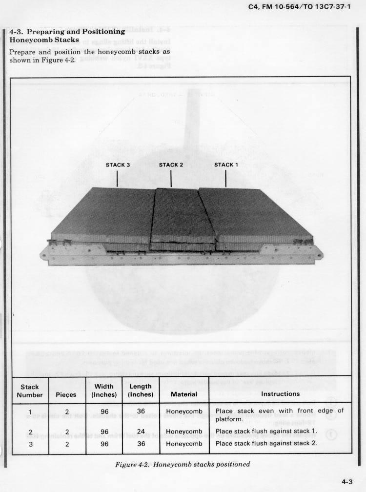
48 4-6. Preparing and Positioning Honeycomb Stacks Prepare and position the honeycomb stacks as shown in Figure 4-. Use eight 36- by 60-inch pieces of honeycomb to make a two-layer stack 60- by 44 inches. Center the stack on the platform. Glue eight 60- by 30-inch pieces of honeycomb flush together. Center this stack on the base layer. Figure 4-. Honeycomb stacks positioned 4-8
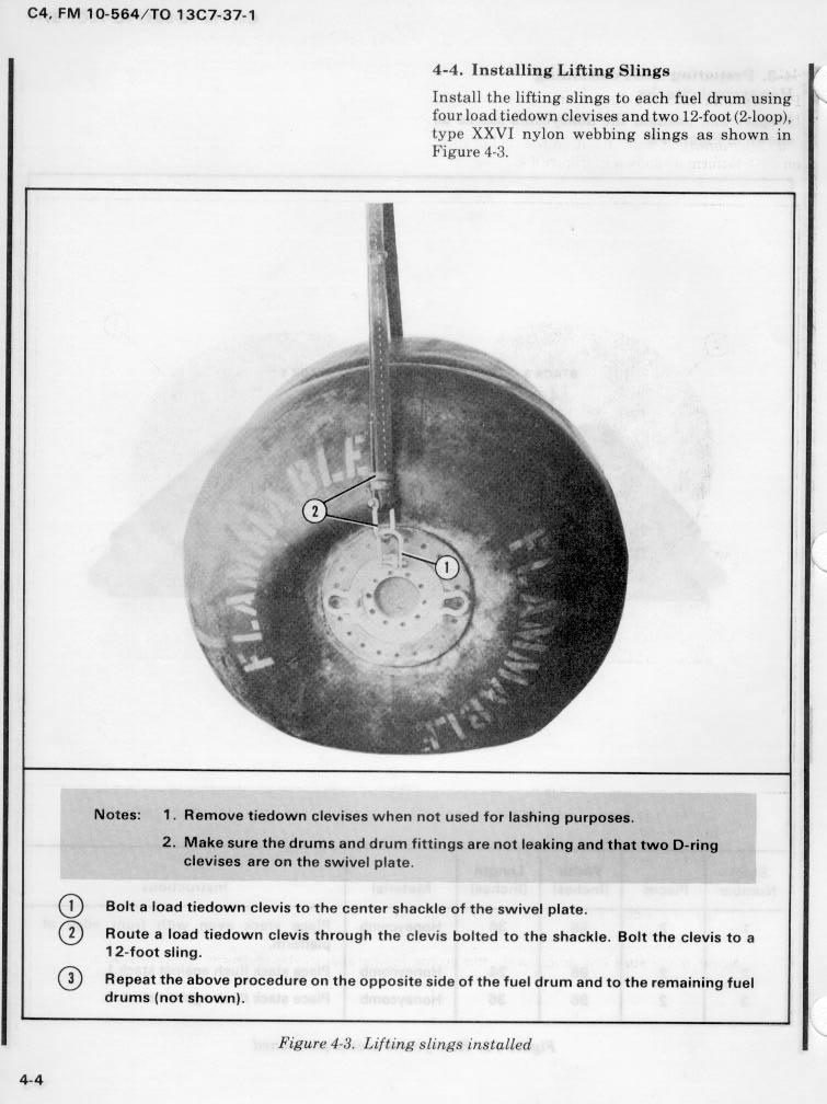
, type XXVI nylon webbing sling to the upper shackle on each side of the drum with a platform clevis.")

49 4-7. Installing Lifting Slings and Positioning Drums Lift the drums and position them on the honeycomb as shown in Figure Attach a 9-foot (-loop), type XXVI nylon webbing sling to the upper shackle on each side of the drum with a platform clevis. Lift a drum onto the front and rear of the honeycomb base as shown. 3 Lash the inside shackles of the two drums together on each side with a 5-foot tiedown assembly. 4 Glue a 60- by 34-inch piece of honeycomb centered on the stack. Glue a 60- by 36-inch piece of honeycomb centered over the piece placed previously. 5 Lift and position a drum onto the honeycomb stack. Figure 4-3. Fuel drums positioned 4-9

50 4-8. Lashing Drums Use twenty 5-foot tie-down assemblies to lash the fuel drums to the platform as shown in Figure 4-4 and according to FM /TO 3C Lashing Number Tie-down Clevis Number A A 3 3A 5 5A Instructions Pass lashing: Through right front shackle of front drum. Through left front shackle of front drum. Through right front shackle of center drum. Through left front shackle of center drum. Through right front shackle of center drum. Through left front shackle of center drum. Through right rear shackle of front drum. Through left rear shackle of front drum. Figure 4-4. Fuel drums lashed to platform 4-0
51 Lashing Number Tie-down Clevis Number 6 6A 8 8A 9 9A 0 0A Instructions Pass lashing: Through right front shackle of rear drum. Through left front shackle of rear drum. Through right rear shackle of center drum. Through left rear shackle of center drum. Through right rear shackle of center drum. Through left rear shackle of center drum. Through right rear shackle of rear drum. Through left rear shackle of rear drum. Figure 4-4. Fuel drums lashed to platform (continued) 4-
, type XXVI nylon webbing sling in the bell portion of a large clevis. Bolt the clevis to a tandem link. Repeat for the other three tandem links.")
52 4-9. Installing and Safetying Suspension Slings Install and safety four -foot (-loop), type XXVI nylon webbing slings to the tandem links as shown in Figure 4-5. Place the end loop of a -foot (-loop), type XXVI nylon webbing sling in the bell portion of a large clevis. Bolt the clevis to a tandem link. Repeat for the other three tandem links. Raise the slings and install the deadman's tie according to FM /TO 3C7--5. Figure 4-5. Suspension slings installed and safetied 4-


53 4-0. Building and Lashing Parachute Stowage Platform Build the parachute stowage platform and lash it to the load with four 5-foot lashings as shown in Figure 4-6. Notes:. This drawing is not to scale.. All dimensions are given in inches. 3. Use eightpenny nails. LUMBER x 6 x 48 PLYWOOD 3/4 x 48 x 96 -in diam holes LUMBER x 6 x 85 3/4 3/ Build the parachute stowage platform as shown. Nail the - by 6-inch pieces of lumber to the edges of the plywood and drill -inch holes for the lashings. Center a piece of honeycomb 48 inches wide and 6 inches long over the rear drum. 3 Place the parachute stowage platform over the honeycomb and the rear drum. Lash the front holes to clevises 4 and 4A. 4 Lash the center and rear holes to clevises 7 and 7A. Figure 4-6. Parachute stowage platform built and lashed 4-3

54 4-. Installing Cargo Parachutes Install three G- cargo parachutes as shown in Figure 4-7 and according to FM /TO 3C Cluster three G- cargo parachutes on the parachute stowage platform. Pass the rear restraint strap through the rear holes in the parachute stowage platform, and tie the ends to the first bushing on the rear tandem links. 3 Pass the front restraint strap through the center holes in the parachute stowage platform, and tie the ends to the 7th bushing on each side of the platform. 4 Install the parachute release knives according to FM /TO 3C7--5. Figure 4-7. G- cargo parachutes installed 4-4

55 4-. Installing Parachute Release Prepare and install an M- cargo parachute release as shown in Figure 4-8 and according to FM /TO 3C Center a 36 -by 36-inch piece of honeycomb over the upper drum. Secure the honeycomb to the drum shackles with type III nylon cord. Attach the suspension slings and riser extensions to the M- release according to FM /TO 3C7--5. Secure the release to the shackles on the lower drums with type III nylon cord. 3 S-fold the suspension slings and tie the folds with type I, /4-inch cotton webbing. Figure 4-8. M- release installed 4-5

, type XXVI nylon webbing sling as the deployment line.")
56 4-3. Installing Extraction System Prepare and install the EFTC extraction system according to FM /TO 3C7--5 and as shown in Figure 4-9. D Install the actuator mounting brackets to the front holes on the left platform rail. Install a -foot cable to the actuator. Install the actuator to the brackets. 3 Attach the latch assembly to the extraction bracket. Attach the cable to the latch assembly. 4 Safety the cable to tiedown ring D6 with type I, /4-inch cotton webbing. 5 Install a 9-foot (-loop), type XXVI nylon webbing sling as the deployment line. S-fold and tie the excess in two places with type I, /4-inch cotton webbing. Figure 4-9. EFTC installed 4-6
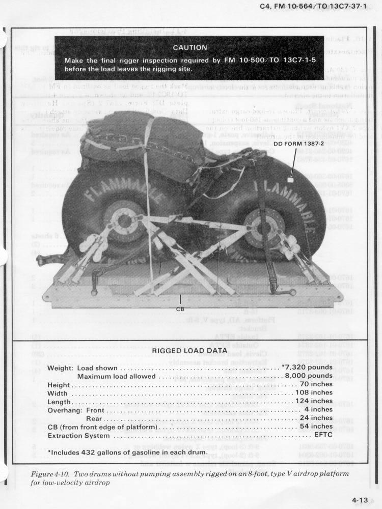
57 4-4. Installing Provisions for Emergency Restraints Select and install provisions for emergency restraints according to the emergency aft restraint requirements table in FM / TO 3C Placing Extraction Parachute Select the extraction parachute and extraction line needed using the extraction line requirements table in FM /TO 3C7--5. Place the extraction parachute and extraction line on the load for installation in the aircraft Marking Rigged Load Mark the rigged load according to FM /TO 3C7--5 and as shown in Figure 4-0. CAUTION The load weight may vary from the one shown, depending upon the fuel rigged. Be sure that the load is weighed, and the parachute requirements, CB, and tip-off curve recomputed Equipment Required Use the equipment listed in Table 4- to rig this load. 4-7
 Height Width Length Overhang Front Rear CB (from front edge of platform) Extraction System (adds 8 inches to length of")
58 CAUTION Make the final rigger inspection required by FM /TO 3C7--5 before the load leaves the rigging site. CB Rigged Load Data Weight: Estimated, with gasoline Maximum (as shown) Height Width Length Overhang Front Rear CB (from front edge of platform) Extraction System (adds 8 inches to length of platform) 0,960 pounds 3,940 pounds 86.5 inches 08 inches 44 inches 5 inches 7 inches 75 inches EFTC Figure 4-0. Three drums without pumping assembly rigged on a -foot, type V airdrop platform for low-velocity airdrop 4-8
59 Table 4-. Equipment required for rigging three drums without pumping assembly on a -foot, type V airdrop platform for low-velocity airdrop National Stock Number Item Quantity Adhesive, paste, -gal As required Clevis, suspension, 3/4-in (medium) Clevis, suspension, -in (large) Cord, nylon, type III, 550-lb As required Coupling, airdrop, extraction force transfer with cable, -ft Cover: Clevis, large Link, type IV Leaf, extraction line (line bag) Line, drogue (for C-7) 60-ft (3-loop), type XXVI Line, extraction: 60-ft (3-loop), type XXVI (for C-30)(Use w/ 40-ft for C-5) 40-ft (3-loop), type XXVI (for C-4B,C-5, or C-7) Link assembly: Type IV Two-point: Bolt, -in diam, 4-in long Nut, -in, hexagonal Plate, side, 3 3/4-in Spacer, large Lumber: - by 6- by 85-in by 48-in Nail, steel wire, 8d As required 7 4-9
60 Table 4-. Equipment required for rigging three drums without pumping assembly on a -foot, type V airdrop platform for low-velocity airdrop (continued) National Stock Number Item Quantity Pad, energy-dissipating (honeycomb) 3- by 36- by 96-in 4 sheets Parachute: Cargo: G-B Cargo extraction: -ft Drogue (for C-7) 5-ft Platform, airdrop, type V, -ft Bracket assembly, coupling Clevis assembly, type V Extraction bracket assembly Tandem link assembly (Multipurpose link) 3 () (0) () (4) Plywood, 3/4 -by 48- by 96-in sheet Release, cargo parachute, M Sling, cargo, airdrop For suspension: -ft (-loop), type XXVI nylon webbing For lifting: 9-ft (-loop), type XXVI nylon webbing For deployment: 9-ft (-loop), type XXVI nylon webbing For riser extension: 0-ft (-loop), type XXVI nylon webbing Strap, parachute release, multi-cut, comes w/ 3 knives Tape, adhesive, -in As required Tie-down assembly, 5-foot Webbing: Cotton, /4-in, type I Nylon, tubular, /-in Type VIII As required As required As required 4-30
61 Section III RIGGING THREE DRUMS WITH PUMPING ASSEMBLY ON A -FOOT PLATFORM 4-8. Description of Load Three drums are rigged with a pumping assembly on a -foot, type V platform. Filled with 43 gallons of gasoline, each drum weighs,84 pounds and is 6 inches long and 53 inches in diameter. An empty drum weighs 50 pounds. Note: Fill drums with no more than 43 gallons of fuel. If the drums are filled with a fuel other than gasoline, the drum weight must be computed Preparing Platform Prepare a -foot, type V airdrop platform using four tandem links and 6 clevises as shown in Figure 4-. Notes:. The nose bumper may or may not be installed.. Measurements given in this section are from the front edge of the platform, NOT from the front edge of the nose bumper. WARNING Do not add air to drums. Pressurization changes will cause leaking or bursting. 4-3
62 CLEVISES 3A THROUGH A TIE-DOWN RINGS TIE-DOWN RINGS D B C LEFT A B A REAR RIGHT CLEVISES 3 THROUGH FRONT Step:. Inspect, or assemble and inspect, the platform as outlined in TM &P/ TO 3C Install a tandem link on the front of each platform side rail using holes,, and 3. Install a tandem link on the rear of each platform side rail using holes, 3, and Bolt a clevis on bushings, and 3 of each front tandem link, and on bushings and 4 of each rear tandem link. 4. Starting at the front of the platform, install clevises on each platform side rail using the bushings bolted on holes 4, 5, 0,, 3, 5, 9 and. 5. Starting at the front of the platform, number the clevises bolted to the right side through 3, and those bolted to the left side A through 3A. 6. Label the tiedown rings according to FM -500-/TO 3C7--5. Figure 4-. Platform prepared 4-3

63 4-30. Preparing and Positioning Honeycomb Stacks Prepare and position the honeycomb stacks as shown in Figure Installing Lifting Slings and Positioning Drums Lift the drums and position them on the honeycomb as shown in Figure Lashing Drums Use twenty-six 5-foot tiedown assemblies to lash the fuel drums to the platform as shown in Figure 4- and according to FM /TO 3C Lashing Number Tie-down Clevis Number A 3 3A 5 5A 7 7A Instructions Pass lashing: Through right front shackle of front drum. Through left front shackle of front drum. Through right front shackle of center drum. Through left front shackle of center drum. Through right front shackle of center drum. Through left front shackle of center drum. Through right rear shackle of front drum. Through left rear shackle of front drum. Figure 4-. Fuel drums lashed to platform 4-33

64 Lashing Number Tie-down Clevis Number 8 8A A A 3 3A Instructions Pass lashing: Through right front shackle of rear drum. Through left front shackle of rear drum. Through right rear shackle of center drum. Through left rear shackle of center drum. Through right rear shackle of center drum. Through left rear shackle of center drum. Through right rear shackle of rear drum. Through left rear shackle of rear drum. Figure 4-. Fuel drums lashed to platform (continued) 4-34
65 4-33. Preparing Pump Assembly Build the box for the pump assembly as shown in Figure 4-3. Pack the pump, hoses, and equipment in the box as shown in Figure 4-4. Notes:. These drawings are not to scale.. Use 8d nails. 3. All dimensions are in inches. 4 / Lashing Pump Assembly to Platform Place the pump assembly box on the load and lash it to the platform as shown in Figure /4 LUMBER x 4 x 5 / BOTTOM 5 / 6 ENDS () LUMBER x 4 x 4 / 7 43 SIDES () 6 7 TOP 4 / Step:. Cut the bottom of the box from 3/4-inch plywood 4 / inches long and 5 / inches wide. Nail a 4 /-inch length of - by 4-inch lumber flat side down and flush along each long edge of the bottom. The top of the box is 43- by 7 inches.. Cut the sides of the box from 3/4-inch plywood 4 / inches long and 6 inches high. Place the sides flush with the bottom. Nail into the - by 4-inch pieces of lumber. 3. Cut the ends of the box from 3/4-inch plywood 7 inches wide and 6 inches high. Nail a piece of - by 4-inch lumber flat side down, centered, and flush with the top edge of each end piece. Nail the ends flush to the bottom and sides. Nail the sides to the - by 4-inch pieces of lumber on the ends. Figure 4-3. Pump assembly box built 4-35

66 3 Place the pump, its hoses, a five-gallon can of fuel, and any other items needed by the unit in the box. Pad the items with cellulose wadding. Nail the top to the box. Place four D-rings onto a 5-foot lashing. Place the lashing around the box lengthwise, and position two D-rings on each end of the box, six inches from each side. Tighten the lashing. 3 Pass two 5-foot lashings around the box and through the D-rings as shown. Tighten the lashings. Figure 4-4. Pump assembly box packed 4-36


67 Cut two pieces of honeycomb the dimensions of the bottom and side of the box. Lift the box onto the front drum using /-inch tubular nylon webbing tied to the D-rings on the ends of the box. Place the honeycomb cut in step between the box and the front and center drums. Secure the honeycomb in place with type III nylon cord. 3 Untie the /-inch tubular nylon webbing placed in step on one side. Retie the webbing tightly between the D-rings on opposite ends of the box to hold the D-rings in position when the box is lashed. 4 Pass a 5-foot lashing through clevis 4 and through its own D-ring. Pass a 5-foot lashing through clevis 4A and through its own D-ring. Secure the two lashings with two D-rings and a load binder on the left side of the load. 5 Pass a 5-foot lashing through clevis and through the right front D-ring. Pass a 5-foot lashing through clevis A and through the left front D-ring. Tighten the lashings at the same time. 6 Pass a 5-foot lashing through clevis 9 and through the right rear D-ring. Pass a 5-foot lashing through clevis 9A and through the left rear D-ring. Tighten the lashings at the same time. Figure 4-5. Pump assembly box lashed to platform 4-37
68 4-35. Installing and Safetying Suspension Slings Install and safety four -foot (-loop), type XXVI nylon webbing slings to the tandem links as shown in Figure Building and Lashing Parachute Stowage Platform Build the parachute stowage platform and lash it to the load as shown in Figure Installing Cargo Parachutes Install three G- cargo parachutes as shown in Figure 4-7 and according to FM /TO 3C Installing Parachute Release Prepare and install an M- cargo parachute release as shown in Figure 4-8 and according to FM /TO 3C Installing Extraction System Prepare and install the EFTC extraction system as shown in Figure 4-9 and according to FM /TO 3C Installing Provisions for Emergency Restraints Select and install provisions for emergency restraints according to the emergency aft restraint requirements table in FM / TO 3C Placing Extraction Parachute Select the extraction parachute and extraction line needed using the extraction line requirements table in FM /TO 3C7--5. Place the extraction parachute and extraction line on the load for installation in the aircraft Marking Rigged Load Mark the rigged load according to FM / TO 3C7--5 and as shown in Figure 4-6. CAUTION The load weight may vary from the one shown, depending upon the fuel rigged. Be sure that the load is weighed, and the parachute requirements, CB, and tip-off curve recomputed Equipment Required Use the equipment listed in Table 4-3 to rig this load. 4-38
 Height Width Length Overhang Front Rear CB (from front edge of platform) Extraction System (adds 8 inches to length of")
69 CAUTION Make the final rigger inspection required by FM /TO 3C7--5 before the load leaves the rigging site. CB Rigged Load Data Weight: Estimated, with gasoline Maximum (as shown) Height Width Length Overhang Front Rear CB (from front edge of platform) Extraction System (adds 8 inches to length of platform),00 pounds 4,80 pounds 86.5 inches 08 inches 44 inches 5 inches 7 inches 74 inches EFTC Figure 4-6. Three drums with pumping assembly rigged on a -foot, type V airdrop platform for low-velocity airdrop. 4-39
70 Table 4-3. Equipment required for rigging three drums with pumping assembly on a -foot, type V airdrop platform for low-velocity airdrop National Stock Number Item Quantity Adhesive, paste, -gal As required Clevis, suspension, 3/4-in (medium) Clevis, suspension, -in (large) Cord, nylon, type III, 550-lb As required Coupling, airdrop, extraction force transfer with cable, -ft Cover: Clevis, large Link, type IV Leaf, extraction line (line bag) Line, drogue (for C-7) 60-ft (3-loop), type XXVI Line, extraction: 60-ft (3-loop), type XXVI (for C-30)(Use w/ 40-ft for C-5) 40-ft (3-loop), type XXVI (for C-4B,C-5, or C-7) Link assembly: Type IV Two-point: Bolt, -in diam, 4-in long Nut, -in, hexagonal Plate, side, 3 3/4-in Spacer, large Lumber: - by 4- by: 4 /-in 5 /-in - by 6- by: 85-in 48-in Nail, steel wire, 8d As required
71 Table 4-3. Equipment required for rigging three drums with pumping assembly on a -foot, type V airdrop platform for low-velocity airdrop (continued) National Stock Number Item Quantity Pad, energy-dissipating (honeycomb) 3- by 36- by 96-in 5 sheets Parachute: Cargo: G-B Cargo extraction: -ft Drogue (for C-7) 5-ft Platform, airdrop, type V, -ft Bracket assembly, coupling Clevis assembly, type V Extraction bracket assembly Tandem link assembly (Multipurpose link) 3 () (6) () (4) Plywood, 3/4 -by 48- by 96-in sheets Release, cargo parachute, M Sling, cargo, airdrop For suspension: -ft (-loop), type XXVI nylon webbing For lifting: 9-ft (-loop), type XXVI nylon webbing For deployment: 9-ft (-loop), type XXVI nylon webbing For riser extension: 0-ft (-loop), type XXVI nylon webbing Strap, parachute release, multi-cut, comes w/ 3 knives Tape, adhesive, -in As required Tie-down assembly, 5-foot Webbing: Cotton, /4-in, type I Nylon, tubular, /-in Type VIII As required As required As required 4-4
72 Section IV RIGGING FOUR DRUMS WITHOUT PUMPING ASSEMBLY ON A 0-FOOT PLATFORM Description of Load Four drums are rigged on a 0-foot, type V platform. Filled with 43 gallons of gasoline, each drum weighs,84 pounds and is 6 inches long and 53 inches in diameter. An empty drum weighs 50 pounds. Note: Fill drums with no more than 43 gallons of fuel. If the drums are filled with a fuel other than gasoline, the drum weight must be computed Preparing Platform Prepare a 0-foot, type V airdrop platform using two tandem links, four suspension links and 0 clevises as shown in Figure 4-7. Notes:. The nose bumper may or may not be installed.. Measurements given in this section are from the front edge of the platform, NOT from the front edge of the nose bumper. WARNING Do not add air to drums. Pressurization changes will cause leaking or bursting. 4-4
73 CLEVISES 0A THROUGH A TIE-DOWN RINGS TIE-DOWN RINGS D B C LEFT A B A RIGHT CLEVISES 0 THROUGH Step:. Inspect, or assemble and inspect, the platform as outlined in TM &P/ TO 3C Install a suspension link on each platform side rail using holes 6, 7, and Install a tandem link on the front of each platform side rail using holes,, and Install a suspension link on each platform side rail using holes 33, 34, and Bolt a clevis on bushing of each front tandem link, on bushing 4 of each first suspension link, and on bushing of each rear suspension link. 6. Starting at the front of the platform, install clevises on each platform side rail using the bushings bolted on holes 4, 7, 5, 6, 30, 39, and Starting at the front of the platform, number the clevises bolted to the right side through 0, and those bolted to the left side A through 0A. 8. Label the tiedown rings according to FM /TO 3C7--5. Figure 4-7. Platform prepared 4-43
74 4-46. Preparing and Positioning Honeycomb Stack Prepare and position the honeycomb stack as shown in Figure 4-8. HONEYCOMB 96" x 8" HONEYCOMB 96" x 36" Use full sheets of honeycomb and two 8- by 96 inch pieces to form a two-layer stack 34 inches long and 96 inches wide. Center the stack on the platform 3 inches from the front edge. Note: Place the 8-inch section inside the stack. Figure 4-8. Honeycomb stack positioned 4-44

75 4-47. Installing Lifting Slings and Positioning Drums Lift the drums and position them on the honeycomb as shown in Figure Lashing Drums Use twenty 5-foot tie-down assemblies to lash the fuel drums as shown in Figure 4-30, and according to FM /TO 3C Attach a 9-foot (-loop), type XXVI nylon webbing sling to the upper shackle on each side of the drum with a platform clevis as shown in Figure 4-3. Lift the drums onto the honeycomb base as shown in Figure Lash the shackles of the drums together on each side with 5-foot tiedown assemblies. Figure 4-9. Fuel drums positioned 4-45

76 Lashing Number Tie-down Clevis Number A A 3 3A 4 4A 5 5A 6 6A 8 8A 0 0A Instructions Pass lashing: Through right front shackle of first drum. Through left front shackle of first drum. Through right front shackle of second drum. Through left front shackle of second drum. Through right rear shackle of first drum. Through left rear shackle of first drum. Through right front shackle of third drum. Through left front shackle of third drum. Through right rear shackle of second drum. Through left rear shackle of second drum. Through right front shackle of fourth drum. Through left front shackle of fourth drum. Through right rear shackle of third drum. Through left rear shackle of third drum. Through right rear shackle of fourth drum. Through left rear shackle of fourth drum. Figure Fuel drums lashed to platform 4-46
77 4-49. Installing and Safetying Suspension Slings Install and safety four 6-foot (4-loop), type XXVI nylon webbing slings to the suspension links as shown in Figure 4-3. Place the end loop of a 6-foot (4-loop), type XXVI nylon webbing sling in the bell portion of a large clevis. Bolt the clevis to a suspension link. Repeat for the other three suspension links. Raise the slings and install the deadman's tie according to FM /TO 3C7--5. Figure 4-3. Suspension slings installed and safetied 4-47

78 4-50. Building and Lashing Parachute Stowage Platform Build the parachute stowage platform and lash it to the load with four 5-foot lashings as shown in Figure 4-3. Notes:. This drawing is not to scale.. All dimensions are given in inches. 3. Use eightpenny nails. 3 LUMBER x 6 x 48 in diam holes PLYWOOD 3/4 x 48 x 96 LUMBER x 6 x 85 3/4 3/ Build the parachute stowage platform as shown. Nail the - by 6-inch pieces of lumber to the edges of the plywood and drill -inch holes for the lashings. Center a 36- by 85-inch piece of honeycomb over the rear drum. Place the parachute stowage platform on the drum over the honeycomb. 3 Lash the two front holes in the parachute stowage platform to clevises 7 and 7A. 4 Lash the two rear holes in the parachute stowage platform to clevises 9 and 9A. Figure 4-3. Parachute stowage platform built and lashed 4-48
79 4-5. Installing Cargo Parachutes Install four G- cargo parachutes as shown in Figure 4-33 and according to FM /TO 3C Cluster four G- cargo parachutes on the parachute stowage platform. Pass the rear restraint strap through the rear holes in the parachute stowage platform, and tie the ends to the 38th bushing on each side rail. 3 Pass the front restraint strap through the center holes in the parachute stowage platform, and tie the ends to the second bushing on each rear suspension link. 4 Install the parachute release knives according to FM /TO 3C7--5. Figure G- cargo parachutes installed 4-49

80 4-5. Installing Parachute Release Prepare and install an M- cargo parachute release as shown in Figure 4-34 and according to FM 0-55-/TO 3C Center a 36- by 96-inch piece of honeycomb over the second and third drums. Secure the ` honeycomb to the platform with type III nylon cord. Attach the suspension slings and the riser extensions to the M- release according to FM /TO 3C7--5. Secure the release to the platform with type III nylon cord. 3 S-fold the suspension slings and tie the folds with type I, /4-inch cotton webbing. Figure M- release installed 4-50

, type XXVI nylon webbing sling as the deployment line. S-fold and tie the excess in two places with type I, /4-inch cotton webbing.")
81 4-53. Installing Extraction System Prepare and install the EFTC extraction system as shown in Figure 4-35 and as shown in FM /TO 3C Install the actuator mounting brackets to the front holes on the left platform rail. Install a 0-foot cable to the actuator. Install the actuator to the brackets. 3 Attach the latch assembly to the extraction bracket. Attach the cable to the latch assembly. 4 Safety the cable to tiedown ring D0 with type I, /4inch cotton webbing. 5 Install a 9-foot (-loop), type XXVI nylon webbing sling as the deployment line. S-fold and tie the excess in two places with type I, /4-inch cotton webbing. Figure EFTC installed 4-5
82 4-54. Installing Provisions for Emergency Restraints Select and install provisions for emergency restraint according to the emergency aft restraint requirements table in FM / TO 3C Placing Extraction Parachute Select the extraction parachute and extraction line needed using the extraction line requirements table in FM /TO 3C7--5. Place the extraction parachute and extraction line on the load for installation in the aircraft Marking Rigged Load Mark the rigged load according to FM / TO 3C7--5 and as shown in Figure CAUTION The load weight may vary from the one shown, depending upon the fuel rigged. Be sure that the load is weighed, and the parachute requirements, CB, and tip-off curve recomputed Equipment Required Use the equipment listed in Table 4-4 to rig this load. 4-5
 Height Width Length Overhang Front Rear CB (from front edge of platform) Extraction System (adds 8 inches to length of")
83 CAUTION Make the final rigger inspection required by FM /TO 3C7--5 before the load leaves the rigging site. CB Rigged Load Data Weight: Estimated, with gasoline Maximum (as shown) Height Width Length Overhang Front Rear CB (from front edge of platform) Extraction System (adds 8 inches to length of platform) 4,46 pounds 8,400 pounds 90.5 inches 08 inches 40 inches 5 inches 7 inches 5 inches EFTC Figure Four drums rigged on a 0-foot, type V airdrop platform for low-velocity airdrop 4-53
84 Table 4-4. Equipment required for rigging four drums without pumping assembly on a 0-foot, type V airdrop platform for low-velocity airdrop National Stock Number Item Quantity Adhesive, paste, -gal As required Clevis, suspension, 3/4-in (medium) Clevis, suspension, -in (large) Cord, nylon, type III, 550-lb As required Coupling, airdrop, extraction force transfer with cable, 0-ft Cover: Clevis, large Link, type IV Leaf, extraction line (line bag) Line, drogue (for C-7) 60-ft (3-loop), type XXVI Line, extraction: 60-ft (3-loop), type XXVI (for C-30)(Use w/ 40-ft for C-5) 40-ft (3-loop), type XXVI (for C-4B,C-5, or C-7) Link assembly: Type IV Lumber: - by 6- by: 85-in 48-in Two-point: Bolt, -in diam, 4-in long Nut, -in, hexagonal Plate, side, 5 /-in Spacer, large Nail, steel wire, 8d As required
85 Table 4-4. Equipment required for rigging four drums without pumping assembly on a 0-foot, type V airdrop platform for low-velocity airdrop (continued) National Stock Number Item Quantity Pad, energy-dissipating (honeycomb) 3- by 36- by 96-in 5 sheets Parachute: Cargo: G-B Cargo extraction: -ft (option for C-4 and C-5) 8-ft (for C-30 and C-7, option for C-4 and C-5) Drogue (for C-7) 5-ft Platform, airdrop, type V, 0-ft Bracket assembly, coupling Clevis assembly, type V Extraction bracket assembly Tandem link assembly (Multipurpose link) Suspension link 4 () (0) () () (4) Plywood, 3/4 -by 48- by 96-in sheet Release, cargo parachute, M Sling, cargo, airdrop For suspension: 6-ft (4-loop), type XXVI nylon webbing For lifting: 9-ft (-loop), type XXVI nylon webbing For deployment: 9-ft (-loop), type XXVI nylon webbing For riser extension: 0-ft (-loop), type XXVI nylon webbing Strap, parachute release, multi-cut, comes w/ 3 knives Tape, adhesive, -in As required Tie-down assembly, 5-foot Webbing: Cotton, /4-in, type I Nylon, tubular, /-in Type VIII As required As required As required 4-55
86 Section V RIGGING FIVE DRUMS WITHOUT PUMPING ASSEMBLY ON A 0-FOOT PLATFORM Description of Load Five drums are rigged on a 0-foot, type V platform. Filled with 43 gallons of gasoline, each drum weighs,84 pounds and is 6 inches long and 53 inches in diameter. An empty drum weighs 50 pounds. Note: Fill drums with no more than 43 gallons of fuel. If the drums are filled with a fuel other than gasoline, the drum weight must be computed Preparing Platform Prepare a 0-foot, type V airdrop platform using two tandem links, eight suspension links and 4 clevises as shown in Figure Notes:. The nose bumper may or may not be installed.. Measurements given in this section are from the front edge of the platform, NOT from the front edge of the nose bumper. CAUTION WARNING Do not add air to drums. Pressurization changes will cause leaking or bursting. 4-56
87 TIE-DOWN RINGS D C B A REAR CLEVISES 9A THROUGH A LEFT RIGHT CLEVISES 9 THROUGH TIE-DOWN RINGS B A FRONT Step:. Inspect, or assemble and inspect, the platform as outlined in TM &P/ TO 3C Install suspension links on each platform side rail using holes 7, 8, and 9, and holes 5, 6, and Install a tandem link on the front of each platform side rail using holes,, and Install suspension links on each platform side rail using holes, 3, and 4, and holes 34, 35, and Bolt clevises on bushings,, and 3 of each front tandem link, on bushing of each second suspension link, on bushings and 4 of each third suspension link, and on bushings 3 and 4 of each rear suspension link. 6. Install clevises on bushings 3 and 39 in an inverted position on each platform side rail. Bolt two additional clevises to each inverted clevis. 7. Starting at the front of the platform, install clevises on each platform side rail using the bushings bolted on holes 9, 4, 5,, 8, 38, and Starting at the front of the platform, number the clevises bolted to the right side through 9, and those bolted to the left side A through 9A. 9. Label the tiedown rings according to FM /TO 3C7--5. Figure Platform prepared 4-57
88 4-60. Preparing and Positioning Honeycomb Stack Prepare and position the honeycomb stack as shown in Figure inch section Use sheets of honeycomb 36- by 60 inches and two pieces 8- by 96 inches to form a twolayer stack 34 inches long and 60 inches wide. Center the stack on the platform 3 inches from the front edge. Note: Place the 8-inch section inside the stack. Make two 8-layer stacks of honeycomb 60- by 30 inches. Center one stack on the base layer 6 / inches from the front edge of the base. 3 Center the other stack on the base layers 55 / inches to the rear of the stack placed in step above. Figure Honeycomb stack positioned 4-58
, type XXVI nylon webbing sling to the upper shackle on each side of the drum with a platform clevis as shown in Figure 4-3.")
89 4-6. Installing Lifting Slings and Positioning Drums Lift the drums and position them on the honeycomb as shown in Figure Attach a 9-foot (-loop), type XXVI nylon webbing sling to the upper shackle on each side of the drum with a platform clevis as shown in Figure 4-3. Lift three drums onto the honeycomb base as shown in Figure Lash the shackles of the drums together on each side with 5-foot tiedown assemblies. 4 Glue a 60- by 34-inch piece of honeycomb centered on each stack. Glue a 60- by 36-inch piece of honeycomb centered over the pieces placed previously. 5 Lift and position a drum onto each stack. Figure Fuel drums positioned 4-59

90 4-6. Lashing Drums Use thirty 5-foot tie-down assemblies to lash the fuel drums as shown in Figure 4-40, and according to FM /TO 3C Lashing Number Tie-down Clevis Number A A 3 3A 4 4A 5 5A Instructions Pass lashing: Through right front shackle of first drum. Through left front shackle of first drum. Through right front shackle of second drum. Through left front shackle of second drum. Through right front shackle of second drum. Through left front shackle of second drum. Through right front shackle of third drum. Through left front shackle of third drum. Through right rear shackle of first drum. Through left rear shackle of first drum. Figure Fuel drums lashed to platform 4-60

91 Lashing Number Tie-down Clevis Number 6 6A 7 7A 8 8A 9 9A 0 0A Instructions Pass lashing: Through right front shackle of fourth drum. Through left front shackle of fourth drum. Through right front shackle of fourth drum. Through left front shackle of fourth drum. Through right rear shackle of first drum. Through left rear shackle of first drum. Through right rear shackle of second drum. Through left rear shackle of second drum. Through right rear shackle of second drum. Through left rear shackle of second drum. Figure Fuel drums lashed to platform (continued) 4-6

92 Lashing Number Tie-down Clevis Number A 3 3A 6 6A 7 7A 9 9A Instructions Pass lashing: Through right rear shackle of third drum. Through left rear shackle of third drum. Through right front shackle of fifth drum. Through left front shackle of fifth drum. Through right rear shackle of fourth drum. Through left rear shackle of fourth drum. Through right rear shackle of fourth drum. Through left rear shackle of fourth drum. Through right rear shackle of fifth drum. Through left rear shackle of fifth drum. Figure Fuel drums lashed to platform (continued) 4-6
93 4-63. Installing and Safetying Suspension Slings Install the components of the centerline suspension system according to FM /TO 3C7--5, and as shown in Figure 4-4. Safety the suspension slings as shown in Figure FT SLING 3-FT SLING Notes:. This drawing is not to scale.. All slings are type XXVI nylon. 3. Instructions are for one side. Repeat for the other side of the load. -FT SLING 5 /-IN -POINT LINK 6-FT SLING (DOUBLED) 3-POINT LINK --FT SLING TWO LARGE CLEVISES 3-FT SLINGS LARGE CLEVISES REAR FRONT Step:. Place the end loop of a -foot (4-loop) sling in the bell portion of a large clevis. Bolt the clevis to the rear suspension link. Connect the free end of the -foot sling to a 3-foot (4-loop) sling with a 5 /-inch two-point link.. Attach a 3-foot (4-loop) sling to each center suspension link with a large clevis. Place both 3-foot slings in the bell portion of a large clevis. Pass a 6-foot (-loop) sling through one spool of a three-point link. Place both end loops of the 6-foot sling in the bolt of the large clevis. 3. Place the end loop of a -foot (4-loop) sling in the bell portion of a large clevis. Place the bolt of the clevis in the bell of a second large clevis. Bolt the second clevis to the front suspension link. Bolt the free end of the -foot sling to the three-point link on the center suspension sling. Bolt a 3-foot (4-loop) sling to the remaining spool of the three-point link. Figure 4-4. Suspension slings installed 4-63
94 3 4 5 Pad the two-point links with felt taped in place. Pad the three-point links with felt taped in place. 3 Attach the 3-foot slings from the two- and three-point links to the crane hook. Raise the suspension slings. 4 Tie the rear suspension slings to each other inches above the load with a double length of /-inch tubular nylon webbing. 5 Tie the front suspension slings to each other in the same way. Figure 4-4. Suspension slings safetied 4-64

95 4-64. Building and Lashing Parachute Stowage Platform Build the parachute stowage platform and its supports as shown in Figure Lash the parachute stowage platform to the load with four 5-foot lashings as shown in Figure Notes:. This drawing is not to scale.. All dimensions are given in inches. 3. Use eightpenny nails. 3/4 LUMBER x 6 x 85 in diam holes 3/4 3/4 4 PLYWOOD 3/4 x 48 x 96 LUMBER x 6 x 48 Make two 7 layer stacks of 8- by 8-inch honeycomb. Place one stack on each side flush with the edge of the honeycomb supporting the rear drum and 9 inches from the rear edge of the platform. Make two 5 layer stacks of - by -inch honeycomb. Glue two 8- by 8-inch pieces of honeycomb on top of each stack flush with the inside front corners. Place the stacks on each side of the rear drum flush with the rear edge of the honeycomb base layer. 3 Center a 48- by 6-inch piece of honeycomb over the rear drum. 4 Build the parachute stowage platform as shown. Nail the - by 6-inch piece of lumber to the edges of the plywood, and drill -inch holes for the lashings. Figure Supports placed and parachute stowage platform constructed 4-65

96 3 8 Center the parachute stowage platform on the honeycomb placed in Figure 4-4. Lash the two rear holes in the parachute stowage platform to clevises 8 and 8A. 3 Lash the two front holes in the parachute stowage platform to clevises and A. Figure Parachute stowage platform lashed to platform rails 4-66


97 4-65. Installing Cargo Parachutes Install five G- cargo parachutes as shown in Figure 4-45, and according to FM /TO 3C Cluster five G- cargo parachutes on the parachute stowage platform. Pass the rear restraint strap through the rear holes in the parachute stowage platform, and tie the ends to clevises 5 and 5A. 3 Pass the front restraint strap through the center holes in the parachute stowage platform, and tie the ends to clevises 4 and 4A. 4 Install the parachute release knives according to FM /TO 3C7--5. Figure G- cargo parachutes installed 4-67

98 4-66. Installing Parachute Release Prepare and install an M- cargo parachute release as shown in Figure 4-46 and according to FM /TO 3C Center a 36- by 36-inch piece of honeycomb over the fourth drum. Secure the honeycomb to the drum shackles with type III nylon cord. Attach the suspension slings and the riser extensions to the M- release according to FM /TO 3C7--5. Secure the release to the platform with type III nylon cord. 3 S-fold the suspension slings and tie the folds with type I, /4-inch cotton webbing. Figure M- release installed 4-68

, type XXVI nylon webbing sling as the deployment line. S-fold and tie the excess in two places with type I, /4-inch cotton webbing.")
99 4-67. Installing Extraction System Prepare and install the EFTC extraction system as shown in Figure 4-47 and as shown in FM /TO 3C Install the actuator mounting brackets to the rear holes on the left platform rail. Install a 0-foot cable to the actuator. Install the actuator to the brackets. 3 Attach the latch assembly to the extraction bracket. Attach the cable to the latch assembly. 4 Safety the cable to tiedown ring C0 with type I, /4inch cotton webbing. 5 Install a 9-foot (-loop), type XXVI nylon webbing sling as the deployment line. S-fold and tie the excess in two places with type I, /4-inch cotton webbing. Figure EFTC installed
100 4-68. Installing Provisions for Emergency Restraints Select and install provisions for emergency restraints according to the emergency aft restraint requirements table in FM / TO 3C Placing Extraction Parachute Select the extraction parachute and extraction line needed using the extraction line requirements table in FM /TO 3C7--5. Place the extraction parachute and extraction line on the load for installation in the aircraft Marking Rigged Load Mark the rigged load according to FM /TO 3C7--5 and as shown in Figure CAUTION The load weight may vary from the one shown, depending upon the fuel rigged. Be sure that the load is weighed, and the parachute requirements, CB and tip-off curve recomputed.re 4-7. Equipment Required -7 Use the equipment listed in Table 4-5 to rig this load. 4-70
 Height Width Length Overhang Front Rear CB (from front edge of platform) Extraction System (adds 8 inches to length of")
101 CAUTION Make the final rigger inspection required by FM / TO 3C7--5 before the load leaves the rigging site. CB Rigged Load Data Weight: Estimated, with gasoline Maximum (as shown) Height Width Length Overhang Front Rear CB (from front edge of platform) Extraction System (adds 8 inches to length of platform) 8,49 pounds 3,460 pounds 84 3/4 inches 08 inches 40 inches 5 inches 7 inches 6 inches EFTC Figure Five drums rigged on a 0-foot, type V airdrop platform for low-velocity airdrop 4-7
102 Table 4-5. Equipment required for rigging five drums without pumping assembly on a 0-foot, type V airdrop platform for low-velocity airdrop. National Stock Number Item Quantity Adhesive, paste, -gal As required Clevis, suspension, 3/4-in (medium) Clevis, suspension, -in (large) Cord, nylon, type III, 550-lb As required Coupling, airdrop, extraction force transfer with cable, 0-ft Cover: Clevis, large Link, type IV Felt, /-in thick As required Leaf, extraction line (line bag) Line, drogue (for C-7) 60-ft (3-loop), type XXVI Line, extraction: 60-ft (3-loop), type XXVI (for C-30)(Use w/ 40-ft for C-5) 40-ft (3-loop), type XXVI (for C-4B,C-5, or C-7) Link assembly: Type IV Three-point Two-point: Bolt, -in diam, 4-in long Nut, -in, hexagonal Plate, side, 5 /-in Spacer, large Lumber, - by 6- by: 85-in 48-in 4-7
103 Table 4-5. Equipment required for rigging five drums without pumping assembly on a 0-foot, type V airdrop platform for low-velocity airdrop (continued) National Stock Number Item Quantity Nail, steel wire, 8d As required Pad, energy-dissipating (honeycomb) 3- by 36- by 96-in 4 sheets Parachute: Cargo: G-C Cargo extraction: 8-ft Drogue (for C-7) 5-ft Platform, airdrop, type V, 0-ft Bracket assembly, coupling Clevis assembly, type V Extraction bracket assembly Tandem link assembly (Multipurpose link) Suspension link () (4) () () (8) Plywood, 3/4 -by 48- by 96-in sheet Release, cargo parachute, M Sling, cargo, airdrop For suspension: 3-ft (4-loop), type XXVI nylon webbing -ft (4-loop), type XXVI nylon webbing 6-ft (-loop), type XXVI nylon webbing For lifting: 9-ft (-loop), type XXVI nylon webbing For deployment: 9-ft (-loop), type XXVI nylon webbing For riser extension: 0-ft (-loop), type XXVI nylon webbing 60-ft (3-loop), type XXVI nylon webbing
104 Table 4-5. Equipment required for rigging five drums without pumping assembly on a 0-foot, type V airdrop platform for low-velocity airdrop (continued) National Stock Number Item Quantity Strap, parachute release, multi-cut, comes w/ 3 knives Tape, adhesive, -in As required Tie-down assembly, 5-foot Webbing: Cotton, /4-in, type I Nylon, tubular, /-in Type VIII As required As required As required 4-74
105 Section VI RIGGING SIX DRUMS WITHOUT PUMPING ASSEMBLY ON A 4-FOOT PLATFORM 4-7. Description of Load Six drums are rigged on a 4-foot, type V platform. Filled with 43 gallons of gasoline, each drum weighs,84 pounds and is 6 inches long and 53 inches in diameter. An empty drum weighs 50 pounds. Note: Fill drums with no more than 43 gallons of fuel. If the drums are filled with a fuel other than gasoline, the drum weight must be computed Preparing Platform Prepare a 4-foot, type V airdrop platform using two tandem links, eight suspension links and 46 clevises as shown in Figure Notes:. The nose bumper may or may not be installed.. Measurements given in this section are from the front edge of the platform, NOT from the front edge of the nose bumper. WARNING Do not add air to drums. Pressurization changes will cause leaking or bursting. 4-75
106 CLEVISES A THROUGH A TIE-DOWN RINGS D C TIE-DOWN RINGS LEFT B B A A REAR FRONT Step: RIGHT CLEVISES THROUGH. Inspect, or assemble and inspect, the platform as outlined in TM &P/ TO 3C Install suspension links on each platform side rail using holes 8, 9, and 0, and holes 6, 7, and Install a tandem link on the front of each platform side rail using holes,, and Install suspension links on each platform side rail using holes 9, 30, and 3, and holes 4, 4, and Bolt clevises on bushings, 3, and 4 of each front tandem link, on bushing 4 of each second suspension link, on bushing of each third suspension link, and on bushings, 3 and 4 of each rear suspension link. 6. Install a clevis on bushing 46 in an inverted position on each platform side rail. Bolt two additional clevises to each inverted clevis. 7. Starting at the front of the platform, install clevises on each platform side rail using the bushings bolted on holes 0, 4,, 3, 6, 7, 35, 37, 38, 45, 47 and Starting at the front of the platform, number the clevises bolted to the right side through, and those bolted to the left side A through A. 9. Label the tiedown rings according to FM /TO 3C7--5. Figure Platform prepared 4-76
107 4-74. Preparing and Positioning Honeycomb Stack Prepare and position the honeycomb stack as shown in Figure inches 57 inches Use 6 sheets of 36- by 60-inch honeycomb to form a two-layer stack 88 inches long and 60 inches wide. Center the stack on the platform flush with the front edge. Make two 8-layer stacks of 60- by 30-inch honeycomb. Center one stack on the base layer 57 inches from the front edge of the base. 3 Center the other stack on the base layers 0 inches to the rear of the stack placed in step above. Figure Honeycomb stack positioned 4-77
, type XXVI nylon webbing sling to the upper shackle on each side of the drum with a platform clevis as shown in Figure 4-3.")
108 4-75. Installing Lifting Slings and Positioning Drums Lift the drums and position them on the honeycomb as shown in Figure Attach a 9-foot (-loop), type XXVI nylon webbing sling to the upper shackle on each side of the drum with a platform clevis as shown in Figure 4-3. Lift four drums onto the honeycomb base as shown in Figure Lash the shackles of the drums together on each side with 5-foot tiedown assemblies. 4 Glue a 60- by 34-inch piece of honeycomb centered on each stack. Glue a 60- by 36-inch piece of honeycomb centered over the pieces placed previously. 5 Lift and position a drum onto each stack. Figure 4-5. Fuel drums positioned 4-78

109 4-76. Lashing Drums Use thirty-four 5-foot tiedown assemblies to lash the fuel drums as shown in Figure 4-5, and according to FM /TO 3C Lashing Number Tie-down Clevis Number A A 3 3A 4 4A 5 5A Instructions Pass lashing: Through right front shackle of first drum. Through left front shackle of first drum. Through right front shackle of second drum. Through left front shackle of second drum. Through right front shackle of second drum. Through left front shackle of second drum. Through right front shackle of third drum. Through left front shackle of third drum. Through right rear shackle of first drum. Through left rear shackle of first drum. Figure 4-5. Fuel drums lashed to platform 4-79

110 Lashing Number Tie-down Clevis Number 6 6A 7 7A 8 8A 9 9A 0 0A A Instructions Pass lashing: Through right front shackle of fourth drum. Through left front shackle of fourth drum. Through right rear shackle of second drum. Through left rear shackle of second drum. Through right rear shackle of second drum. Through left rear shackle of second drum. Through right front shackle of fifth drum. Through left front shackle of fifth drum. Through right front shackle of fifth drum. Through left front shackle of fifth drum. Through right rear shackle of third drum. Through left rear shackle of third drum. Figure 4-5. Fuel drums lashed to platform (continued) 4-80

111 Lashing Number Tie-down Clevis Number A 4 4A 8 8A 9 9A A A Instructions Pass lashing: Through right front shackle of sixth drum. Through left front shackle of sixth drum. Through right rear shackle of fourth drum. Through left rear shackle of fourth drum. Through right rear shackle of fifth drum. Through left rear shackle of fifth drum. Through right rear shackle of sixth drum. Through left rear shackle of sixth drum. Through right rear shackle of fifth drum. Through left rear shackle of fifth drum. Through right rear shackle of sixth drum. Through left rear shackle of sixth drum. Figure 4-5. Fuel drums lashed to platform (continued) 4-8
112 4-77. Installing and Safetying Suspension Slings Install the components of the centerline suspension system according to FM /TO 3C7--5, and as shown in Figure Safety the suspension slings as shown in Figure POINT LINK 3-FT SLING Notes:. This drawing is not to scale.. All slings are type XXVI nylon. 3. Instructions are for one side. Repeat for the other side of the load. 5 /-IN -POINT LINK 3-FT SLING 9-FT SLING 6-FT SLING (DOUBLED) 6-FT SLING Step: REAR LARGE CLEVISES FRONT. Place the end loop of a 9-foot (4-loop) sling in the bell portion of a large clevis. Bolt the clevis to the rear suspension link. Connect the free end of the 9-foot sling to a 3-foot (4-loop) sling with a 5 /-inch two-point link.. Attach a 3-foot (4-loop) sling to each center suspension link with a large clevis. Place both 3-foot slings in the bell portion of a large clevis. Pass a 6-foot (-loop) sling through one spool of a three-point link. Place both end loops of the 6-foot sling in the bolt of the large clevis. 3. Bolt the free end of the rear suspension sling to the three-point link placed in step so that the remaining spool of the three-point link points upward. Bolt a 3-foot (4-loop) sling to the remaining spool. 4. Place the end loop of a 6-foot (4-loop) sling in the bell portion of a large clevis. Bolt the clevis to the front suspension link. Figure Suspension slings installed 4-8

113 3 4 3 Pad the two-point links and the three-point links with felt taped in place. Attach the front suspension slings and the 3-foot slings from the three-point links to the crane hook. Raise the suspension slings. 3 Tie the rear suspension slings to each other inches above the load with a double length of /-inch tubular nylon webbing. Tie the front suspension slings to each other in the same way. 4 Tie a length of /-inch tubular nylon webbing between the shackles of the second and fifth drums and under the center suspension slings. Make this tie as taut as possible. Figure Suspension slings safetied 4-83

114 5 6 5 Pass a length of /4-inch, type I cotton webbing through the plies of the center suspension slings at the clevis bolt. Pass the ends up and over the /-inch tubular nylon webbing placed in step 4 so that the nylon webbing is kept in a horizontal position. Tie the cotton webbing to the outside of the slings. 6 Tie the front suspension slings to the upper shackle on the second drum with a length of type III nylon cord. Tie the rear suspension slings to the fifth drum in the same way. Figure Suspension slings safetied (continued) 4-84

115 4-78. Building and Lashing Parachute Stowage Platform Build the parachute stowage platform and its supports as shown in Figure Lash the parachute stowage platform to the load as shown in Figure Notes:. This drawing is not to scale.. All dimensions are given in inches. 3. Use eightpenny nails. 3/4 LUMBER x 6 x 85 in diam holes 3/4 PLYWOOD 3/4 x 48 x 96 4 LUMBER x 6 x 48 Make two 7-layer stacks of 8- by 8-inch honeycomb. Place one stack on each side flush with the edge of the honeycomb supporting the rear drum and 9 inches from the rear edge of the platform. Make two 5-layer stacks of - by -inch honeycomb. Glue two 8- by 8-inch pieces of honeycomb on top of each stack flush with the inside front corners. Place the stacks on each side of the rear drum flush with the rear edge of the honeycomb base layer. 3 Center a 48- by 6-inch piece of honeycomb over the rear drum. 4 Build the parachute stowage platform as shown. Nail the - by 6-inch pieces of lumber to the edges of the plywood, and drill -inch holes for the lashings. Figure Supports placed and parachute stowage platform constructed 4-85

116 3 3 0 Center the parachute stowage platform on the honeycomb placed in Figure -54. Lash the two rear holes in the parachute stowage platform to clevises 0 and 0A. 3 Lash the two front holes in the parachute stowage platform to clevises 3 and 3A. Figure Parachute stowage platform lashed to platform rails. 4-86


117 4-79. Installing Cargo Parachutes Install six G- cargo parachutes as shown in Figure 4-57, and restrain them with type X nylon webbing according to FM /TO 3C Cluster six G- cargo parachutes on the parachute stowage platform. Place an additional clevis on clevises 5, 5A, 6, 6A, 7, and 7A. Place the added clevises in an inverted position. 3 Pass the rear restraint strap through the rear holes in the parachute stowage platform, and attach the ends to the curves of clevises 7 and 7A with D-rings and load binders. 4 Pass the center restraint strap through the center holes in the parachute stowage platform, and attach the ends to the curves of clevises 6 and 6A with D-rings and load binders. 5 Pass the front restraint strap through the front holes in the parachute stowage platform, and attach the ends to the curves of clevises 5 and 5A with D-rings and load binders. 6 Install the parachute release knives according to FM /TO 3C7--5. Figure G- cargo parachutes installed 4-87

118 4-80. Installing Parachute Release Prepare and install an M- cargo parachute release as shown in Figure 4-58 and according to FM /TO 3C Center a 36- by 36-inch piece of honeycomb over the fifth drum. Secure the honeycomb to the drum shackles with type III nylon cord. Attach the suspension slings and the riser extensions to the M- release according to FM /TO 3C7--5. Secure the release to the platform with type III nylon cord. 3 S-fold the suspension slings and tie the folds with type I, /4-inch cotton webbing. Figure M- release installed 4-88

, type XXVI nylon webbing sling as the deployment line.")
119 4-8. Installing Extraction System Prepare and install the EFTC extraction system as shown in Figure 4-59 and as shown in FM /TO 3C Install the actuator mounting brackets to the rear holes on the left platform rail. Install a 4-foot cable to the actuator. Install the actuator to the brackets. 3 Attach the latch assembly to the extraction bracket. Attach the cable to the latch assembly. 4 Install a 9-foot (-loop), type XXVI nylon webbing sling as the deployment line. S-fold and tie the excess in two places with type I, /4-inch cotton webbing. 3 Figure EFTC installed 4-89
120 4-8. Installing Provisions for Emergency Restraints Select and install provisions for emergency restraints according to the emergency aft restraint requirements table in FM / TO 3C Placing Extraction Parachute Select the extraction parachute and extraction line needed using the extraction line requirements table in FM /TO 3C7--5. Place the extraction parachute and extraction line on the load for installation in the aircraft Marking Rigged Load Mark the rigged load according to FM /TO 3C7--5 and as shown in Figure CAUTION The load weight may vary from the one shown, depending upon the fuel rigged. Be sure that the load is weighed, and the parachute requirements, CB, and tip-off curve recomputed Equipment Required Use the equipment listed in Table 4-6 to rig this load. 4-90
 Height Width Length Overhang Front Rear CB (from front edge of platform) Extraction System (adds 8 inches to length of")
121 CAUTION Make the final rigger inspection required by FM /TO 3C7--5 before the load leaves the rigging site. CB Rigged Load Data Weight: Estimated, with gasoline Maximum (as shown) Height Width Length Overhang Front Rear CB (from front edge of platform) Extraction System (adds 8 inches to length of platform),58 pounds 8,0 pounds 85 inches 08 inches 88 inches 5 inches 7 inches 53 inches EFTC Figure Six drums rigged on a 4-foot, type V airdrop platform for low-velocity airdrop 4-9
122 Table 4-6. Equipment required for rigging six drums without pumping assembly on a 4-foot, type V airdrop platform for low-velocity airdrop National Stock Number Item Quantity Adhesive, paste, -gal As required Clevis, suspension, 3/4-in (medium) Clevis, suspension, -in (large) Cord, nylon, type III, 550-lb As required Coupling, airdrop, extraction force transfer with cable, 4-ft Cover: Clevis, large Link, type IV Felt, /-in thick As required Leaf, extraction line (line bag) Line, drogue (for C-7) 60-ft (3-loop), type XXVI Line, extraction: 60-ft (3-loop), type XXVI (for C-30)(Use w/ 40-ft for C-5) 40-ft (3-loop), type XXVI (for C-4B,C-5, or C-7) Link assembly: Three-point Type IV Two-point: Bolt, -in diam, 4-in long Nut, -in, hexagonal Plate, side, 5 /-in Spacer, large Lumber: - by 6- by: 85-in 48-in 4-9
123 Table 4-6. Equipment required for rigging six drums without pumping assembly on a 4-foot, type V airdrop platform for low-velocity airdrop (continued) National Stock Number Item Quantity Nail, steel wire, 8d As required Pad, energy-dissipating (honeycomb) 3- by 36- by 96-in 6 sheets Parachute: Cargo: G-C Cargo extraction: 8-ft Drogue (for C-7) 5-ft Platform, airdrop, type V, 4-ft Bracket assembly, coupling Clevis assembly, type V Extraction bracket assembly Tandem link assembly (Multipurpose link) Suspension link () (48) () () (8) Plywood, 3/4 -by 48- by 96-in sheet Release, cargo parachute, M Sling, cargo, airdrop For suspension: 3-ft (4-loop), type XXVI nylon webbing 9-ft (4-loop), type XXVI nylon webbing 6-ft (-loop), type XXVI nylon webbing For lifting: 9-ft (-loop), type XXVI nylon webbing For deployment: 9-ft (-loop), type XXVI nylon webbing For riser extension: 0-ft (-loop), type XXVI nylon webbing
124 Table 4-6. Equipment required for rigging six drums without pumping assembly on a 4-foot, type V airdrop platform for low-velocity airdrop (continued) National Stock Number Item Quantity Strap, parachute release, multi-cut, comes w/ 3 knives Tape, adhesive, -in As required Tie-down assembly, 5-foot Webbing: Cotton, /4-in, type I Nylon, tubular, /-in Type X As required As required As required 4-94
125 Section VII RIGGING SIX DRUMS WITH PUMPING ASSEMBLY ON A 4-FOOT PLATFORM Description of Load Six drums are rigged with a pumping assembly on a 4-foot, type V platform. Filled with 43 gallons of gasoline, each drum weighs,84 pounds and is 6 inches long and 53 inches in diameter. An empty drum weighs 50 pounds. Note: Fill drums with no more than 43 gallons of fuel. If the drums are filled with a fuel other than gasoline, the drum weight must be computed Preparing Platform Prepare a 4-foot, type V airdrop platform using two tandem links, eight suspension links and 5 clevises as shown in Figure 4-6. Notes:. The nose bumper may or may not be installed.. Measurements given in this section are from the front edge of the platform, NOT from the front edge of the nose bumper. WARNING Do not add air to drums. Pressurization changes will cause leaking or bursting. 4-95
126 TIE-DOWN RINGS D C B A REAR CLEVISES 5A THROUGH A LEFT RIGHT CLEVISES 5 THROUGH TIE-DOWN RINGS B A FRONT Step:. Inspect, or assemble and inspect, the platform as outlined in TM &P/ TO 3C Install suspension links on each platform side rail using holes 8, 9, and 0, and holes 6, 7, and Install a tandem link on the front of each platform side rail using holes,, and Install suspension links on each platform side rail using holes 9, 30, and 3, and holes 4, 4, and Bolt clevises on bushings, 3, and 4 of each front tandem link, on bushing 4 of each second suspension link, on bushing of each third suspension link, and on bushings, 3 and 4 of each rear suspension link. 6. Install a clevis on bushing 46 in an inverted position on each platform side rail. Bolt two additional clevises to each inverted clevis. 7. Starting at the front of the platform, install clevises on each platform side rail using the bushings bolted on holes 0, 4, 6,, 3, 5, 6, 7, 34, 35, 37, 38, 45, 47 and Starting at the front of the platform, number the clevises bolted to the right side through 5, and those bolted to the left side A through 5A. 9. Label the tie-down rings according to FM /TO 3C7--5. Figure 4-6. Platform prepared 4-96
127 4-88. Preparing and Positioning Honeycomb Stacks Prepare and position the honeycomb stack as shown in Figure 4-50 found in Section VI Lashing Drums Use fifty 5-foot tiedown assemblies to lash the fuel drums as shown in Figure 4-6, and according to FM /TO 3C Installing Lifting Slings and Positioning Drums Lift the drums and position them on the honeycomb as shown in Figure 4-5 found in Section VI. 4-97
128 Lashing Number Tie-down Clevis Number A A 3 3A 4 4A 5 5A Instructions Pass lashing: Through right front shackle of first drum. Through left front shackle of first drum. Through right front shackle of second drum. Through left front shackle of second drum. Through right front shackle of second drum. Through left front shackle of second drum. Through right front shackle of third drum. Through left front shackle of third drum. Through right rear shackle of first drum. Through left rear shackle of first drum. Figure 4-6. Fuel drums lashed to platform 4-98

129 Lashing Number Tie-down Clevis Number 7 7A 8 8A 9 9A A A 3 3A Instructions Pass lashing: Through right front shackle of fourth drum. Through left front shackle of fourth drum. Through right rear shackle of second drum. Through left rear shackle of second drum. Through right rear shackle of second drum. Through left rear shackle of second drum. Through right front shackle of fifth drum. Through left front shackle of fifth drum. Through right front shackle of fifth drum. Through left front shackle of fifth drum. Through right rear shackle of third drum. Through left rear shackle of third drum. Figure 4-6. Fuel drums lashed to platform (continued) 4-99

130 Lashing Number Tie-down Clevis Number 5 5A 7 7A A A 4 4A 5 5A Instructions Pass lashing: Through right front shackle of sixth drum. Through left front shackle of sixth drum. Through right rear shackle of fourth drum. Through left rear shackle of fourth drum. Through right rear shackle of fifth drum. Through left rear shackle of fifth drum. Through right front shackle of sixth drum. Through left front shackle of sixth drum. Through right rear shackle of fifth drum. Through left rear shackle of fifth drum. Through right rear shackle of sixth drum. Through left rear shackle of sixth drum. Figure 4-6. Fuel drums lashed to platform (continued) 4-00
131 4-9. Preparing Pump Assembly Build the box for the pump assembly as shown in Figure Pack the pump assembly and hoses in the box as shown in Figure Lashing Pump Assembly to Platform Place the pump assembly box on the load and lash it to the platform as shown in Figure Notes:. These drawings are not to scale.. Use 8d nails. 3. All dimensions are in inches. 4 / 3/4 LUMBER x 4 x 5 / BOTTOM 5 / ENDS () 6 7 LUMBER x 4 x 4 / 4 / 43 SIDES () 6 TOP 7 Step:. Cut the bottom of the box from 3/4-inch plywood 4 / inches long and 5 / inches wide. Nail a 4 /-inch length of - by 4-inch lumber flat side down and flush along each long edge of the bottom. The top of the box is 43- by 7 inches.. Cut the sides of the box from 3/4-inch plywood 4 / inches long and 6 inches high. Place the sides flush with the bottom. Nail into the - by 4-inch pieces of lumber. 3. Cut the ends of the box from 3/4-inch plywood 7 inches wide and 6 inches high. Nail a piece of - by 4-inch lumber flat side down, centered, and flush with the top edge of each end piece. Nail the ends flush to the bottom and sides. Nail the sides to the - by 4-inch pieces of lumber on the ends. Figure Pump assembly box built 4-0
132 3 Place the pump, its hoses, a five-gallon can of fuel, and any other items needed by the unit in the box. Pad the items with cellulose wadding. Nail the top to the box. Place four D-rings onto a 5-foot lashing. Place the lashing around the box lengthwise, and position two D-rings on each end of the box, six inches from each side. Tighten the lashing. 3 Pass two 5-foot lashings around the box and through the D-rings as shown. Tighten the lashings. Figure Pump assembly box packed 4-0


133 Center and glue a 56- by 36-inch piece of 3/4-inch plywood between two 60 -by 36-inch pieces of honeycomb. Place the honeycomb and plywood centered over the third and fourth drums. Place the box centered on the honeycomb and plywood. Secure the box lashings to the honeycomb with type III nylon cord. 3 Lash the right front D-ring on the box to clevis 6. Lash the left front D-ring to clevis 6A. 4 Lash the right rear D-ring on the box to clevis 4. Lash the left rear D-ring to clevis 4A. 5 Pass lashings through clevises 0 and 0A and through their own D-rings. Secure the lashings together on one side of the load with two D-rings and a load binder. Figure Pump assembly box lashed to platform 4-03
134 4-93. Installing and Safetying Suspension Slings Install the components of the centerline suspension sling system according to FM /TO 3C7--5, and as shown in Figure 4-43 found in Section VI. Safety the suspension slings as shown in Figure 4-54 found in Section VI Building and Lashing Parachute Stowage Platform Build the parachute stowage platform and its supports as shown in Figure Lash the parachute stowage platform to the load as shown in Figure
135 3 6 3 Center the parachute stowage platform on the honeycomb placed in Figure Rest the front edge of the platform against the fifth drum. Lash the two rear holes in the platform to clevises 3 and 3A. 3 Lash the two front holes in the platform to clevises 6 and 6A. Figure Parachute stowage platform lashed to platform rails 4-05
136 4-95. Installing Cargo Parachutes Install six G- cargo parachutes as shown in Figure 4-67, and according to FM /TO 3C Cluster six G- cargo parachutes on the parachute stowage platform. Place an additional clevis on clevises 8, 8A, 9, 9A, 0, and 0A. Place the added clevises in an inverted position. 3 Pass the rear restraint strap through the rear holes in the parachute stowage platform, and attach the ends to the curves of clevises 0 and 0A with D-rings and load binders. 4 Pass the center restraint strap through the center holes in the parachute stowage platform, and attach the ends to the curves of clevises 9 and 9A with D-rings and load binders. 5 Pass the front restraint strap through the front holes in the parachute stowage platform, and attach the ends to the curves of clevises 8 and 8A with D-rings and load binders. 6 Install the parachute release knives according to FM /TO 3C7--5. Figure G- cargo parachutes installed 4-06
137 4-96. Installing Parachute Release Prepare and install an M- cargo parachute release as shown in Figure 4-48, and according to FM /TO 3C Center the M- release assembly over the rear half of the pump box. Secure the release to the load with type III nylon cord. Attach the suspension slings and the riser extensions to the M- release according to FM /TO 3C S-fold the suspension slings and tie the folds with type I, /4-inch cotton webbing. Figure M- release installed 4-07
138 4-97. Installing Extraction System Prepare and install the EFTC extraction system as shown in Figure 4-59 found in Section VI, and according to FM /TO 3C Installing Provisions for Emergency Restraints Select and install provisions for emergency restraints according to the emergency aft restraint requirements table in FM / TO 3C Placing Extraction Parachute Select the extraction parachute and extraction line needed using the extraction line requirements table in FM /TO 3C7--5. Place the extraction parachute and extraction line on the load for installation in the aircraft Marking Rigged Load Mark the rigged load according to FM /TO 3C7--5 and as shown in Figure CAUTION The load weight may vary from the one shown, depending upon the fuel rigged. Be sure that the load is weighed, and the parachute requirements, CB, and tip-off curve recomputed Equipment Required Use the equipment listed in Table 4-7 to rig this load. 4-08
 Height Width Length Overhang Front Rear CB (from front edge of platform) Extraction System (adds 8 inches to length of")
139 CAUTION Make the final rigger inspection required by FM /TO 3C7--5 before the load leaves the rigging site. CB Rigged Load Data Weight: Estimated, with gasoline Maximum (as shown) Height Width Length Overhang Front Rear CB (from front edge of platform) Extraction System (adds 8 inches to length of platform),548 pounds 8,40 pounds 9 inches 08 inches 88 inches 5 inches 7 inches 50 inches EFTC Figure Six drums with pumping assembly rigged on a 4-foot, type V airdrop platform for low-velocity airdrop 4-09
140 Table 4-7. Equipment required for rigging six drums with pumping assembly on a 4-foot, type V airdrop platform for low-velocity airdrop National Stock Number Item Quantity Adhesive, paste, -gal As required Clevis, suspension, 3/4-in (medium) Clevis, suspension, -in (large) Cord, nylon, type III, 550-lb As required Coupling, airdrop, extraction force transfer with cable, 4-ft Cover: Clevis, large Link, type IV Felt, /-in thick As required Leaf, extraction line (line bag) Line, drogue (for C-7) 60-ft (3-loop), type XXVI Line, extraction: 60-ft (3-loop), type XXVI (for C-30)(Use w/ 40-ft for C-5) 40-ft (3-loop), type XXVI (for C-4B,C-5, or C-7) Link assembly: Three-point Type IV Two-point: Bolt, -in diam, 4-in long Nut, -in, hexagonal Plate, side, 5 /-in Spacer, large Lumber: - by 4- by: 5 / 4 / - by 6- by: 85-in 48-in
141 Table 4-7. Equipment required for rigging six drums with pumping assembly on a 4-foot, type V airdrop platform for low-velocity airdrop (continued) National Stock Number Item Quantity Nail, steel wire, 8d As required Pad, energy-dissipating (honeycomb) 3- by 36- by 96-in 8 sheets Parachute: Cargo: G-C Cargo extraction: 8-ft Drogue (for C-7) 5-ft Platform, airdrop, type V, 4-ft Bracket assembly, coupling Clevis assembly, type V Extraction bracket assembly Tandem link assembly (Multipurpose link) Suspension link () (5) () () (8) Plywood, 3/4 -by 48- by 96-in sheets Release, cargo parachute, M Sling, cargo, airdrop For suspension: 3-ft (4-loop), type XXVI nylon webbing 9-ft (4-loop), type XXVI nylon webbing 6-ft (-loop), type XXVI nylon webbing For lifting: 9-ft (-loop), type XXVI nylon webbing For deployment: 9-ft (-loop), type XXVI nylon webbing For riser extension: 0-ft (-loop), type XXVI nylon webbing
142 Table 4-7. Equipment required for rigging six drums with pumping assembly on a 4-foot, type V airdrop platform for low-velocity airdrop (continued) National Stock Number Item Quantity Strap, parachute release, multi-cut, comes w/ 3 knives Tape, adhesive, -in As required Tie-down assembly, 5-foot Webbing: Cotton, /4-in, type I Nylon, tubular, /-in Type X As required As required As required 4-
143 Section VIII RIGGING SEVEN DRUMS WITHOUT PUMPING ASSEMBLY ON A 8-FOOT PLATFORM 4-0. Description of Load Seven drums are rigged on a 8-foot, type V platform. Filled with 43 gallons of gasoline, each drum weighs,84 pounds and is 6 inches long and 53 inches in diameter. An empty drum weighs 50 pounds. Note: Fill drums with no more than 43 gallons of fuel. If the drums are filled with a fuel other than gasoline, the drum weight must be computed Preparing Platform Prepare a 8-foot, type V airdrop platform using two tandem links, eight suspension links and 50 clevises as shown in Figure Notes:. The nose bumper may or may not be installed.. Measurements given in this section are from the front edge of the platform, NOT from the front edge of the nose bumper. WARNING Do not add air to drums. Pressurization changes will cause leaking or bursting. 4-3
144 TIE-DOWN RINGS D C B A CLEVISES 5A THROUGH A LEFT TIE-DOWN RINGS B A RIGHT FRONT REAR Step: CLEVISES 5 THROUGH. Inspect, or assemble and inspect, the platform as outlined in TM &P/ TO 3C Install suspension links on each platform side rail using holes, 3, and 4, and holes 6, 7, and Install a tandem link on the front of each platform side rail using holes,, and Install suspension links on each platform side rail using holes 33, 34, and 35, and holes 49, 50, and Bolt clevises on bushings, 3, and 4 of each front tandem link, on bushings and 4 of each second suspension link, on bushing 3 of each third suspension link, and on bushings and 4 of each rear suspension link. 6. Starting at the front of the platform, install clevises on each platform side rail using the bushings bolted on holes 0, 3, 4, 6, 5, 8, 9, 3, 37, 40, 4, 43, 46, 53, 54, 55 and Starting at the front of the platform, number the clevises bolted to the right side through 5, and those bolted to the left side A through 5A. 8. Label the tiedown rings according to FM /TO 3C7--5. Figure Platform prepared 4-4
145 C6. FM 0-564/TO 3C Preparing and Positioning Honeycomb Stacks Prepare and position the honeycomb stack as shown in Figure 4-7. HONEYCOMB 60 X 36 HONEYCOMB 60 X 36 HONEYCOMB 60 X 4 3 Use 8 pieces of 36- by 60-inch honeycomb, and two - by 60-inch pieces of honeycomb to form a two-layer stack 336 inches long and 60 inches wide. Center the stack on the platform flush with the front edge. Note: Place the -inch section inside the stack. Make three 8-layer stacks of 60- by 30-inch honeycomb. Center a stack on the base layer 57 inches from the front edge of the base. 3 Center a second 8-layer stack of honeycomb 57 inches to the rear of the first. 4 Center the third 8-layer stack of honeycomb on the base layers 57 inches to the rear of the stack placed in step 3 above. Figure 4-7. Honeycomb stack positioned 4-5
, type XXVI nylon webbing sling to the upper shackle on each side of the drum with a platform clevis as shown in Figure 4-3.")
146 4-05. Installing Lifting Slings and Positioning Drums Lift the drums and position them on the honeycomb as shown in Figure Attach a 9-foot (-loop), type XXVI nylon webbing sling to the upper shackle on each side of the drum with a platform clevis as shown in Figure 4-3. Lift four drums onto the honeycomb base as shown. 3 Lash the shackles of the drums together on each side with 5-foot tiedown assemblies. 4 Glue a 60- by 34-inch piece of honeycomb centered on each stack. Glue a 60- by 36-inch piece of honeycomb centered over the pieces placed previously. 5 Lift and position a drum onto each stack. Figure 4-7. Fuel drums positioned 4-6

147 C6. FM 0-564/TO 3C Lashing Drums Use fifty 5-foot tie-down assemblies to lash the fuel drums as shown in Figure 4-73, and according to FM /TO 3C Lashing Number Tie-down Clevis Number A A 3 3A 4 4A 5 5A Instructions Pass lashing: Through right front shackle of first drum. Through left front shackle of first drum. Through right front shackle of second drum. Through left front shackle of second drum. Through right front shackle of second drum. Through left front shackle of second drum. Through right front shackle of third drum. Through left front shackle of third drum. Through right rear shackle of first drum. Through left rear shackle of first drum. Figure Fuel drums lashed to platform 4-7

148 Lashing Number Tie-down Clevis Number 6 6A 7 7A 8 8A 9 9A 0 0A A Instructions Pass lashing: Through right front shackle of fourth drum. Through left front shackle of fourth drum. Through right front shackle of fourth drum. Through left front shackle of fourth drum. Through right rear shackle of second drum. Through left rear shackle of second drum. Through right rear shackle of second drum. Through left rear shackle of second drum. Through right front shackle of fifth drum. Through left front shackle of fifth drum. Through right rear shackle of third drum. Through left rear shackle of third drum. Figure Fuel drums lashed to platform (continued) 4-8

149 C6. FM 0-564/TO 3C Lashing Number Tie-down Clevis Number A 3 3A 4 4A 5 5A 6 6A 7 7A 0 0A A 5 5A Instructions Pass lashing: Through right front shackle of sixth drum. Through left front shackle of sixth drum. Through right front shackle of sixth drum. Through left front shackle of sixth drum. Through right rear shackle of fourth drum. Through left rear shackle of fourth drum. Through right rear shackle of fourth drum. Through left rear shackle of fourth drum. Through right rear shackle of fifth drum. Through left rear shackle of fifth drum. Through right front shackle of seventh drum. Through left front shackle of seventh drum. Through right rear shackle of sixth drum. Through left rear shackle of sixth drum. Through right rear shackle of sixth drum. Through left rear shackle of sixth drum. Through right rear shackle of seventh drum. Through left rear shackle of seventh drum. Figure Fuel drums lashed to platform (continued) 4-9
150 4-07. Installing and Safetying Suspension Slings Install the components of the centerline suspension system according to FM /TO 3C7--5, and as shown in Figure Safety the suspension slings as shown in Figure Notes:. This drawing is not to scale.. All slings are type XXVI nylon. 3. Instructions are for one side. Repeat for the other side of the load. 3-FOOT SLING 3-POINT LINK 6-FOOT SLING -FOOT SLING 0-FOOT SLING REAR 3-FOOT SLINGS LARGE CLEVISES TWO LARGE CLEVISES FRONT Step:. Place the end loop of a 0-foot (4-loop) sling in the bell portion of a large clevis. Bolt the clevis to the rear suspension link.. Attach a 3-foot (4-loop) sling to each center suspension link with a large clevis. Place both 3-foot slings in the bell portion of a large clevis. Place an end loop of an -foot (4-loop) sling through one spool of a three-point link. Place the other end loop of the -foot sling in the bolt of the large clevis. 3. Place the end loop of a 6-foot (4-loop) sling in the bell portion of a large clevis. Place the bolt of the clevis in the bell of a second large clevis. Bolt the second clevis to the front suspension link. Bolt the free end of the 6-foot sling to the three-point link on the center suspension sling. Bolt a 3-foot (4-loop) sling to the remaining spool of the three-point link. Figure Suspension slings installed 4-0

151 C6. FM 0-564/TO 3C Pad the three-point links with felt taped in place. Attach the rear suspension slings and the 3-foot slings from the three-point links to the crane hook. Raise the suspension slings. 3 Tie the rear suspension slings to each other inches above the load with a double length of /-inch tubular nylon webbing. Tie the front suspension slings to each other in the same way. 4 Tie the front suspension slings to the upper shackle on the second drum with a length of type III nylon cord. Tie the rear suspension slings to the sixth drum in the same way. 5 Tie the upper clevises on the center suspension slings to the nearest shackle on the fourth drum with type III nylon cord. Figure Suspension slings safetied 4-

152 4-08. Building and Lashing Parachute Stowage Platform Build the parachute stowage platform and its supports as shown in Figure Lash the parachute stowage platform to the load as shown in Figure Notes:. This drawing is not to scale.. All dimensions are given in inches. 3. Use eightpenny nails. 3/4 3/4 LUMBER X 6 X 85 PLYWOOD 3/4 X 48 X 96 IN DIAM HOLES 4 LUMBER X 6 X 48 Make two 7-layer stacks of 8- by 8-inch honeycomb. Place one stack on each side flush with the edge of the honeycomb supporting the rear drum and 9 inches from the rear edge of the platform. Make two 5-layer stacks of - by -inch honeycomb. Glue two 8- by 8-inch pieces of honeycomb on top of each stack flush with the inside front corners. Place the stacks on each side of the rear drum flush with the rear edge of the honeycomb base layer. 3 Center one or two 48- by 6-inch pieces of honeycomb over the rear drum. 4 Build the parachute stowage platform as shown. Nail the - by 6-inch pieces of lumber to the edges of the plywood, and drill -inch holes for the lashings. Figure Supports placed and parachute stowage platform constructed 4-

153 C6. FM 0-564/TO 3C Center the parachute stowage platform on the honeycomb placed in Figure Remove or add honeycomb if necessary for a snug fit. Lash the two rear holes in the parachute stowage platform to clevises 3 and 3A. 3 Lash the two front holes in the parachute stowage platform to clevises 8 and 8A. Figure Parachute stowage platform lashed to platform rails 4-3


154 4-09. Installing Cargo Parachutes Install seven G- cargo parachutes as shown in Figure 4-78, and according to FM /TO 3C Cluster seven G- cargo parachutes on the parachute stowage platform. Pass the rear restraint strap through the rear holes in the parachute stowage platform, and attach the ends to inverted clevises 4 and 4A with D-rings and load binders. 3 Pass the center restraint strap through the center holes in the parachute stowage platform, and attach the ends to inverted clevises and A with D-rings and load binders. 4 Pass the front restraint strap through the front holes in the parachute stowage platform, and attach the ends to inverted clevises 9 and 9A with D-rings and load binders. 5 Install the parachute release knives according to FM /TO 3C7--5. Figure G- cargo parachutes installed 4-4

155 C6. FM 0-564/TO 3C Installing Parachute Release Prepare and install an M- cargo parachute release as shown in Figure 4-79, and according to FM /TO 3C Center a 36 -by 36-inch piece of honeycomb over the sixth drum. Secure the honeycomb to the drum shackles with type III nylon cord. Attach the suspension slings and the riser extensions to the M- release according to FM /TO 3C7--5. Secure the release to the platform with type III nylon cord. 3 S-fold the suspension slings and tie the folds with type I, /4-inch cotton webbing. Figure M- release installed 4-5

, type XXVI nylon webbing sling as the deployment line.")
156 4-. Installing Extraction System Prepare and install the EFTC extraction system as shown in Figure 4-80, and according to FM /TO 3C Install the actuator mounting brackets to the rear holes on the left platform rail. Install a 8-foot cable to the actuator. Install the actuator to the brackets. 3 Attach the latch assembly to the extraction bracket. Attach the cable to the latch assembly. 4 Install a 9-foot (-loop), type XXVI nylon webbing sling as the deployment line. S-fold and tie the excess in two places with type I, /4-inch cotton webbing. Figure EFTC installed 4-6
157 4-. Installing Provisions for Emergency Restraints Select and install provisions for emergency restraints according to the emergency aft restraint requirements table in FM / TO 3C Placing Extraction Parachute Select the extraction parachute and extraction line needed using the extraction line requirements table in FM /TO 3C7--5. Place the extraction parachute and extraction line on the load for installation in the aircraft Marking Rigged Load Mark the rigged load according to FM /TO 3C7--5 and as shown in Figure 4-8. CAUTION The load weight may vary from the one shown, depending upon the fuel rigged. Be sure that the load is weighed, and the parachute requirements, CB, and tip-off curve recomputed Equipment Required Use the equipment listed in Table 4-8 to rig this load. 4-7
 3,735 pounds Height 90 inches Width 08 inches Length 336 inches Overhang Front 5 inches Rear 7 inches CB (from")
158 CAUTION Make the final rigger inspection required by FM /TO 3C7--5 before the load leaves the rigging site. CB Rigged Load Data Weight: Estimated, with gasoline 4,78 pounds Maximum (as shown) 3,735 pounds Height 90 inches Width 08 inches Length 336 inches Overhang Front 5 inches Rear 7 inches CB (from front edge of platform) 76 inches Extraction System (adds 8 inches to length of platform) EFTC Figure 4-8. Seven drums rigged on a 8-foot, type V airdrop platform for low-velocity airdrop 4-8
159 C6. FM 0-564/TO 3C7-37- Table 4-8. Equipment required for rigging seven drums without pumping assembly on a 8-foot, type V airdrop platform for low-velocity airdrop National Stock Number Item Quantity Adhesive, paste, -gal As required Clevis, suspension, 3/4-in (medium) Clevis, suspension, -in (large) Cord, nylon, type III, 550-lb As required Coupling, airdrop, extraction force transfer with cable, 8-ft Cover: Clevis, large Link, type IV Felt, /-in thick As required Leaf, extraction line (line bag) NO NSN Line, drogue (for C-7) 60-ft (3-loop), type XXVI Line, extraction: 60-ft (6-loop), type XXVI (for C-30) 0-ft (6-loop), type XXVI (for C-4B or C-5) 40-ft (6-loop), type XXVI (for C-7) Link assembly: Three-point Type IV Four-point Lumber: - by 6- by: 85-in 48-in 8 4-9
160 Table 4-8. Equipment required for rigging seven drums without pumping assembly on a 8-foot, type V airdrop platform for low-velocity airdrop (continued) National Stock Number Item Quantity Nail, steel wire, 8d As required Pad, energy-dissipating (honeycomb) 3- by 36- by 96-in 3 sheets Parachute: Cargo: G-C Cargo extraction: 8-ft Drogue (for C-7) 5-ft Platform, airdrop, type V, 8-ft Bracket assembly, coupling Clevis assembly, type V Extraction bracket assembly Tandem link assembly (Multipurpose link) Suspension link 7 () (50) () () (8) Plywood, 3/4 -by 48- by 96-in sheet Release, cargo parachute, M Sling, cargo, airdrop For suspension: 3-ft (4-loop), type XXVI nylon webbing -ft (4-loop), type XXVI nylon webbing 6-ft (4-loop), type XXVI nylon webbing 0-ft (4-loop), type XXVI nylon webbing For lifting: 9-ft (-loop), type XXVI nylon webbing For deployment: 9-ft (-loop), type XXVI nylon webbing For riser extension: 0-ft (-loop), type XXVI nylon webbing
161 Table 4-8. Equipment required for rigging seven drums without pumping assembly on a 8-foot, type V airdrop platform for low-velocity airdrop (continued) National Stock Number Item Quantity Strap, parachute release, multi-cut, comes w/ 3 knives Tape, adhesive, -in As required Tie-down assembly, 5-foot Webbing: Cotton, /4-in, type I Nylon, tubular, /-in Type X As required As required As required 4-3
162 Section IX RIGGING SEVEN DRUMS WITH PUMPING ASSEMBLY ON A 8-FOOT PLATFORM 4-6. Description of Load Seven drums are rigged with the pumping assembly on a 8-foot, type V platform. Filled with 43 gallons of gasoline, each drum weighs,84 pounds and is 6 inches long and 53 inches in diameter. An empty drum weighs 50 pounds. Note: Fill drums with no more than 43 gallons of fuel. If the drums are filled with a fuel other than gasoline, the drum weight must be computed Preparing Platform Prepare a 8-foot, type V airdrop platform using two tandem links, eight suspension links and 54 clevises as shown in Figure 4-8. Notes:. The nose bumper may or may not be installed.. Measurements given in this section are from the front edge of the platform, NOT from the front edge of the nose bumper. WARNING Do not add air to drums. Pressurization changes will cause leaking or bursting. 4-3
163 TIE-DOWN RINGS D C B A REAR Step: CLEVISES 6A THROUGH A LEFT RIGHT CLEVISES 6 THROUGH TIE-DOWN RINGS B A FRONT. Inspect, or assemble and inspect, the platform as outlined in TM &P/ TO 3C Install suspension links on each platform side rail using holes, 3, and 4, and holes 6, 7, and Install a tandem link on the front of each platform side rail using holes,, and Install suspension links on each platform side rail using holes 33, 34, and 35, and holes 49, 50, and Bolt clevises on bushings, 3, and 4 of each front tandem link, on bushings and 4 of each second suspension link, on bushing of each third suspension link, and on bushings and 4 of each rear suspension link. 6. Install a clevis on bushings 54 and 55 in an inverted position on each platform side rail. Bolt one additional clevis to each inverted clevis. 7. Starting at the front of the platform, install clevises on each platform side rail using the bushings bolted on holes 0, 4, 7, 8, 6, 30, 3, 37, 40, 4, 4, 44, 46, 53, and Starting at the front of the platform, number the clevises bolted to the right side through 6, and those bolted to the left side A through 6A. 9. Label the tie-down rings according to FM /TO 3C7--5. Figure 4-8. Platform prepared 4-33
164 4-8. Preparing and Positioning Honeycomb Stack Prepare and position the honeycomb stack as shown in Figure inches 57 inches Use 8 pieces of 36- by 60-inch honeycomb, and two pieces - by 60 inches to form a two-layer stack 336 inches long and 60 inches wide. Center the stack on the platform flush with the front edge. Note: Place the -inch section inside the stack. Make two 8-layer stacks of 60- by 30-inch honneycomb. Center a stack on the base layer 57 inches from the front edge of the base. 3 Center the other stack on the base layers 63 inches to the rear of the stack placed in step. Figure Honeycomb stack positioned 4-34
, type XXVI nylon webbing sling to the upper shackle on each side of the drum with a platform clevis as shown in Figure 4-3.")
165 4-9. Installing Lifting Slings and Positioning Drums Lift the drums and position them on the honeycomb as shown in Figure Attach a 9-foot (-loop), type XXVI nylon webbing sling to the upper shackle on each side of the drum with a platform clevis as shown in Figure 4-3. Lift five drums onto the honeycomb base as shown. 3 Lash the shackles of the drums together on each side with 5-foot tie-down assemblies. 4 Glue a 60- by 34-inch piece of honeycomb centered on each stack. Glue a 60- by 36-inch piece of honeycomb centered over the pieces placed previously. 5 Lift and position a drum onto each stack. Figure Fuel drums positioned 4-35

166 4-0. Lashing Drums Use thirty-eight 5-foot tie-down assemblies to lash the fuel drums to the platform as shown in Figure 4-85, and according to FM /TO 3C Lashing Number Tie-down Clevis Number A A 3 3A 4 4A 5 5A Instructions Pass lashing: Through right front shackle of first drum. Through left front shackle of first drum. Through right front shackle of second drum. Through left front shackle of second drum. Through right front shackle of second drum. Through left front shackle of second drum. Through right front shackle of third drum. Through left front shackle of third drum. Through right rear shackle of first drum. Through left rear shackle of first drum. Figure Fuel drums lashed to platform 4-36

167 Lashing Number Tie-down Clevis Number 7 7A 8 8A 9 9A 0 0A A Instructions Pass lashing: Through right front shackle of fourth drum. Through left front shackle of fourth drum. Through right rear shackle of second drum. Through left rear shackle of second drum. Through right rear shackle of second drum. Through left rear shackle of second drum. Through right front shackle of fifth drum. Through left front shackle of fifth drum. Through right rear shackle of third drum. Through left rear shackle of third drum. Figure Fuel drums lashed to platform (continued) 4-37

168 Lashing Number Tie-down Clevis Number 3 3A 4 4A 5 5A 8 8A 0 0A A 3 3A 4 4A 6 6A Instructions Pass lashing: Through right front shackle of sixth drum. Through left front shackle of sixth drum. Through right front shackle of sixth drum. Through left front shackle of sixth drum. Through right rear shackle of fourth drum. Through left rear shackle of fourth drum. Through right front shackle of seventh drum. Through left front shackle of seventh drum. Through right rear shackle of fifth drum. Through left rear shackle of fifth drum. Through right rear shackle of sixth drum. Through left rear shackle of sixth drum. Through right rear shackle of sixth drum. Through left rear shackle of sixth drum. Through right rear shackle of seventh drum. Through left rear shackle of seventh drum. Through right rear shackle of seventh drum. Through left rear shackle of seventh drum. Figure Fuel drums lashed to platform (continued) 4-38
169 4-. Preparing Pump Assembly Build the box for the pump assembly as shown in Figure Pack the pump assembly and hoses in the box as shown in Figure Notes:. These drawings are not to scale.. Use 8d nails. 3. All dimensions are in inches. 4 / 4-. Lashing Pump Assembly to Platform Place the pump assembly box on the load and lash it to the platform as shown in Figure /4 LUMBER x 4 x 5 / BOTTOM 5 / ENDS () 6 LUMBER x 4 x 4 / 7 4 / 43 SIDES () 6 TOP 7 Step:. Cut the bottom of the box from 3/4-inch plywood 4 / inches long and 5 / inches wide. Nail a 4 /-inch length of - by 4-inch lumber flat side down and flush along each long edge of the bottom. The top of the box is 43- by 7 inches.. Cut the sides of the box from 3/4-inch plywood 4 / inches long and 6 inches high. Place the sides flush with the bottom. Nail into the -by 4-inch pieces of lumber. 3. Cut the ends of the box from 3/4-inch plywood 7 inches wide and 6 inches high. Nail a 5 /- inch piece of - by 4-inch lumber flat side down, centered, and flush with the top edge of each end piece. Nail the ends flush to the bottom and sides. Nail the sides to the - by 4-inch pieces of lumber on the ends. Figure Pump assembly box built 4-39

170 3 Place the pump, its hoses, a 5-gallon can of fuel, and any other items needed by the unit in the box. Pad the items with cellulose wadding. Nail the top to the box. Place four D-rings onto a 5-foot lashing. Place the lashing around the box lengthwise, and position two D-rings on each end of the box, 6 inches from each side. Tighten the lashing. 3 Pass two 5-foot lashings around the box and through the D-rings as shown. Tighten the lashings. Figure Pump assembly box packed 4-40

171 3 6 6 Center two 96- by 36-inch pieces of honeycomb over the third, fourth, and fifth drums. Tape the edges of the honeycomb and secure the honeycomb to the load with type III nylon cord. Center the pump box on the honeycomb with the D-rings facing the front and rear. Lash the right front D-ring on the box to clevis 6. Lash the left front D-ring to clevis 6A. 3 Lash the right rear D-ring on the box to clevis 6. Lash the left rear D-ring to clevis 6A. Figure Pump assembly box lashed to platform 4-4
172 4-3. Installing and Safetying Suspension Slings Install the components of the centerline suspension system according to FM /TO 3C7--5 and as shown in Figure Safety the suspension slings as shown in Figure Notes. This drawing is not to scale.. All slings are type XXVI nylon. 3. Instructions are for one side. Repeat for the other side of the load. 3-FOOT SLING 3-POINT LINK 6-FOOT SLING 0-FOOT SLING -FOOT SLING LARGE CLEVISES THREE LARGE CLEVISES Step: REAR 3-FOOT SLINGS FRONT. Place the end loop of a 0-foot (4-loop) sling in the bell portion of a large clevis. Bolt the clevis to the rear suspension link.. Attach a 3-foot (4-loop) sling to each center suspension link with a large clevis. Place both 3-foot slings in the bell portion of a large clevis. Place an end loop of an -foot (4-loop) sling through one spool of a three-point link. Place the other end loop of the -foot sling in the bolt of the large clevis. 3. Place the end loop of a 6-foot (4-loop) sling in the bell portion of a large clevis. Place the bolt of the clevis in the bell of a second large clevis. Attach the second clevis to the front suspension link with a third large clevis. Bolt the free end of the 6-foot sling to the three-point link on the center suspension sling. Bolt a 3-foot (4-loop) sling to the remaining spool of the three-point link. Figure Suspension slings installed 4-4
173 3 4 Pad the three-point links with felt taped in place. Attach the rear suspension slings and the 3-foot slings from the three-point links to the crane hook. Raise the suspension slings. 3 Tie the rear suspension slings to each other inches above the load with a double length of /-inch tubular nylon webbing. Adapt the procedures in Figure 3-, FM /TO 3C7--5 to tie and tape the webbing. Tie the front suspension slings to each other in the same way. 4 Tie a length of /-inch tubular nylon webbing between the inside shackles of the second and sixth drums and behind the center suspension slings. Make this tie as taut as possible. Figure Suspension slings safetied 4-43

174 5 6 5 Pass a length of /4-inch, type I cotton webbing through the plies of the center suspension slings at the clevis bolt. Pass the ends up and over the /-inch tubular nylon webbing placed in step 4 so that the nylon webbing is kept in a horizontal position. Tie the cotton webbing to the outside of the slings. 6 Tie the front suspension slings to the upper shackle on the second drum with a length of type III nylon cord. Tie the rear suspension slings to the sixth drum in the same way. Figure Suspension slings safetied (continued) 4-44

175 4-4. Building and Lashing Parachute Stowage Platform Build the parachute stowage platform and its supports as shown in Figure 4-76, found in Section VIII. Lash the parachute stowage platform to the load as shown in Figure Center the parachute stowage platform on the honeycomb placed in Figure Lash the two rear holes in the parachute stowage platform to clevises 3 and 3A. 3 Lash the two front holes in the parachute stowage platform to clevises 6 and 6A. Figure 4-9. Parachute stowage platform lashed to platform rails 4-45

176 4-5. Installing Cargo Parachutes Install seven G- cargo parachutes as shown in Figure 4-9, and according to FM /TO 3C Cluster seven G- cargo parachutes on the parachute stowage platform. Pass the rear restraint strap through the rear holes in the parachute stowage platform, and attach the ends to the lower clevises of 5 and 5A with D-rings and load binders. 3 Pass the center restraint strap through the center holes in the parachute stowage platform, and attach the ends to inverted clevises and A with D-rings and load binders. 4 Pass the front restraint strap through the front holes in the parachute stowage platform, and attach the ends to inverted clevises 9 and 9A with D-rings and load binders. 5 Install the parachute release knives according to FM /TO 3C7--5. Figure 4-9. G- cargo parachutes installed 4-46

177 4-6. Installing Parachute Release Prepare and install an M- cargo parachute release as shown in Figure 4-93, and according to FM /TO 3C Center the M- release assembly on the pump box. Secure the release to the load with type III nylon cord. Attach the suspension slings and the riser extensions to the M- release according to FM /TO 3C S-fold the suspension slings and tie the folds with type I, /4-inch cotton webbing. Figure M- release installed 4-47
178 4-7. Installing Extraction System Prepare and install the EFTC extraction system as shown in Figure 4-80 in Section VIII, and according to FM /TO 3C Installing Provisions for Emergency Restraints Select and install provisions for emergency restraint according to the emergency aft restraint requirements table in FM / TO 3C Placing Extraction Parachute Select the extraction parachute and extraction line needed using the extraction line requirements table in FM /TO 3C7--5. Place the extraction parachute and extraction line on the load for installation in the aircraft Marking Rigged Load Mark the rigged load according to FM /TO 3C7--5 and as shown in Figure CAUTION The load weight may vary from the one shown, depending upon the fuel rigged. Be sure that the load is weighed, and the parachute requirements, CB, and tip-off curve recomputed Equipment Required Use the equipment listed in Table 4-9 to rig this load. 4-48
 Height Width Length Overhang Front Rear CB (from front edge of platform) Extraction System (adds 8 inches to length of")
179 CAUTION Make the final rigger inspection required by FM /TO 3C7--5 before the load leaves the rigging site. CB Rigged Load Data Weight: Estimated, with gasoline Maximum (as shown) Height Width Length Overhang Front Rear CB (from front edge of platform) Extraction System (adds 8 inches to length of platform) 5,08 pounds 3,35 pounds 90 inches 08 inches 336 inches 5 inches 7 inches 76 inches EFTC Figure Seven drums with pumping assembly rigged on a 8-foot, type V airdrop platform for low-velocity airdrop 4-49
RIGGING ROAD ROLLERS C7, FM /TO 13C
 RIGGING ROAD ROLLERS C7, FM 10-528/TO 13C7-26-71 C7, FM 10-528/TO 13C7-26-71 CHANGE 5 May 2000 NO. 7 AIRDROP OF SUPPLIES AND EQUIPMENT: RIGGING ROAD ROLLERS This change adds the procedures for rigging
RIGGING ROAD ROLLERS C7, FM /TO 13C
 RIGGING ROAD ROLLERS C7, FM 10-528/TO 13C7-26-71 C7, FM 10-528 TO 13C7-26-71 By Order of the Secretary of the Army: Official: ERIC K. SHINSEKI General, United States Army Chief of Staff JOEL B. HUDSON
AIRDROP OF SUPPLIES AND EQUIPMENT: RIGGING FORWARD AREA REFUELING EQUIPMENT (FARE) AND ADVANCED AVIATION FORWARD AREA REFUELING SYSTEM (AAFARS)
 AND ADVANCED AVIATION FORWARD AREA REFUELING SYSTEM (AAFARS)") FM 4-0.37 (FM 0-537) AIR FORCE TO 3C7--9 AIRDROP OF SUPPLIES AND EQUIPMENT: RIGGING FORWARD AREA REFUELING EQUIPMENT (FARE) AND ADVANCED AVIATION FORWARD AREA REFUELING SYSTEM (AAFARS) JUNE 003 DISTRIBUTION
FM 4-0.37 (FM 0-537) AIR FORCE TO 3C7--9 AIRDROP OF SUPPLIES AND EQUIPMENT: RIGGING FORWARD AREA REFUELING EQUIPMENT (FARE) AND ADVANCED AVIATION FORWARD AREA REFUELING SYSTEM (AAFARS) JUNE 003 DISTRIBUTION
6-6. Install the lashings and secure pre-positioned lashings as shown in Figures 6-8 through 6-15.
 Chapter 6 LOADING AND CLOSING THE BOXES 6-5. Load and close the boxes as described below. Use the tiedown rings inside the box to secure the load, if necessary. Use honeycomb, if necessary, to cover the
Headquarters Department of the Army Department of the Air Force
 FM 4-20.121(FM 4-20.121 and FM 10-539) TO 13C7-6-21 Airdrop of Supplies and Equipment: Rigging Tractors and Tractor-Dozers September 2007 DISTRIBUTION RESTRICTION. Approved for public release; distribution
AIRDROP OF SUPPLIES AND EQUIPMENT: RIGGING COMMUNICATION CONTROL VEHICLES
 AIRDROP OF SUPPLIES AND EQUIPMENT: RIGGING COMMUNICATION CONTROL VEHICLES DISTRIBUTION RESTRICTION: Approved for public release; distribution is unlimited. HEADQUARTERS DEPARTMENT OF THE ARMY DEPARTMENT
AIRDROP OF SUPPLIES AND EQUIPMENT: RIGGING HIGH-MOBILITY MULTIPURPOSE WHEELED VEHICLES
 HEADQUARTERS DEPARTMENT OF THE ARMY UNITED STATES MARINE CORPS DEPARTMENT OF THE AIR FORCE CHANGE NO. 1 Washington, DC, AIRDROP OF SUPPLIES AND EQUIPMENT: RIGGING HIGH-MOBILITY MULTIPURPOSE WHEELED VEHICLES
RIGGING HIGH-MOBILITY MULTIPURPOSE WHEELED VEHICLES
 ARMY FM 4-20.117 (FM 10-517) AIR FORCE TO 13C7-1-111 AIRDROP OF SUPPLIES AND EQUIPMENT: RIGGING HIGH-MOBILITY MULTIPURPOSE WHEELED VEHICLES HEADQUARTERS DEPARTMENT OF THE ARMY DEPARTMENT OF THE AIR FORCE
RIGGING HIGH-MOBILITY MULTIPURPOSE WHEELED VEHICLES
 ARMY FM 4-20.117 (FM 10-517) AIR FORCE TO 13C7-1-111 AIRDROP OF SUPPLIES AND EQUIPMENT: RIGGING HIGH-MOBILITY MULTIPURPOSE WHEELED VEHICLES HEADQUARTERS DEPARTMENT OF THE ARMY DEPARTMENT OF THE AIR FORCE
AIR TRANSPORTABILITY GUIDANCE TWO M151 1/4-TON TRUCKS AND ONE 1/4-TON TRAILER IN CH-47 HELICOPTER
 TM -2320-218-10-3 DEPARTMENT OF THE ARMY TECHNICAL MANUAL AIR TRANSPORTABILITY GUIDANCE TWO M11 1/4-TON TRUCKS AND ONE 1/4-TON TRAILER IN CH-47 HELICOPTER Headquarters, Department of the Army, Washington,
Manual Provided by emilitary Manuals -
 ARMY FM 4-20 116 (FM 10-516) AIR FORCE TO 13C7-1-13 AIRDROP OF SUPPLIES AND EQUIPMENT: Reference Data for Airdrop Platform Loads DISTRIBUTION RESTRICTION: Approved for public release; distribution is unlimited
The U.S. Army Pathfinder School Nomenclature
 The U.S. Army Pathfinder School Nomenclature Common Sling Load Equipment Note: Students are required to know both proper nomenclature and all rated capacities. Information (in parenthesis) is not testable.
ARNG WTC Pathfinder MTT. Common Slingload Equipment
 ARNG WTC Pathfinder MTT Slingloads Nomenclature Packet Common Slingload Equipment Note: Students are required to know both proper nomenclature and all rated capacities. Information (in parenthesis) is
AIR TRANSPORTABILITY GUIDANCE TWO M151 1/4-TON TRUCKS AND ONE 1/4-TON TRAILER IN CH-47 HELICOPTER
 TM -2320-218-10-3 DEPARTMENT OF THE ARMY TECHNICAL MANUAL AIR TRANSPORTABILITY GUIDANCE TWO M11 1/4-TON TRUCKS AND ONE 1/4-TON TRAILER IN CH-47 HELICOPTER Headquarters, Department of the Army, Washington,
19 Pad the face of the PDB and the PLU with cellulose wadding taped in place.
 21 20 19 19 Pad the face of the PDB and the PLU with cellulose wadding taped in place. 20 Place a 17- by 19 1/2-inch piece of honeycomb on top of the PLU. Crush the honeycomb to allow for the printer mount
AIR TRANSPORTABILITY GUIDANCE M151 1/4-TON TRUCK AND M100 1/4-TON TRAILER IN CH-17 HELlCOPTER
 TM 55-2320-218-10-2 DEPARTMENT OF THE ARMY TECHNICAL MANUAL AIR TRANSPORTABILITY GUIDANCE M151 1/4-TON TRUCK AND M100 1/4-TON TRAILER IN CH-17 HELlCOPTER Headquarters, Department of the Army, Washington,
TACTICAL VEHICLES: INSTALLATION OF UNIVERSAL TIEDOWN ANCHORS
 TECHNICAL BULLETIN FOR TACTICAL VEHICLES: INSTALLATION OF UNIVERSAL TIEDOWN ANCHORS Approved for public release; distribution is unlimited. HEADQUARTERS, DEPARTMENT OF THE ARMY * TB 9-2300-280-30 Technical
Headquarters Department of the Army Department of the Air Force
 FM 4-20.116 TO 13C7-1-13 Airdrop of Supplies and Equipment: Reference Data for Airdrop Platform Loads MAY 2006 DISTRIBUTION RESTRICTION: Approved for public release; distribution is unlimited Headquarters
TECHNICAL MANUAL TRANSPORTABILITY GUIDANCE GRADER, ROAD, MOTORIZED, DIESEL-ENGINE-DRIVEN (DED) HEAVY, COMMERCIAL CONSTRUCTION EQUIPMENT (CCE)
 HEAVY, COMMERCIAL CONSTRUCTION EQUIPMENT (CCE)") TECHNICAL MANUAL TRANSPORTABILITY GUIDANCE GRADER, ROAD, MOTORIZED, DIESEL-ENGINE-DRIVEN (DED) HEAVY, COMMERCIAL CONSTRUCTION EQUIPMENT (CCE) MODEL 130G MIL NSN 3805-01-150-4795 MODEL 130G TYPE I (NONSECTIONALIZED)
TECHNICAL MANUAL TRANSPORTABILITY GUIDANCE GRADER, ROAD, MOTORIZED, DIESEL-ENGINE-DRIVEN (DED) HEAVY, COMMERCIAL CONSTRUCTION EQUIPMENT (CCE) MODEL 130G MIL NSN 3805-01-150-4795 MODEL 130G TYPE I (NONSECTIONALIZED)
PETROLEUM LABORATORY TESTING AND OPERATIONS
 * FM 10-67-2 Field Manual No. 10-67-2 HEADQUARTERS DEPARTMENT OF THE ARMY Washington, DC, 2 April 1997 PETROLEUM LABORATORY TESTING AND OPERATIONS Table of Contents Page PREFACE CHAPTER 1 I CHAPTER 2 I
US ARMY TM US MARINE CORPS TM 08580B-1 0/1 TECHNICAL MANUAL OPERATOR S MANUAL TABLE OF CONTENTS
 US ARMY TM 10-4610-239-10 US MARINE CORPS TM 08580B-1 0/1 TECHNICAL MANUAL OPERATOR S MANUAL WATER PURIFICATION UNIT, REVERSE OSMOSIS, 600 GPH TRAILER MOUNTED FLATBED CARGO, 5 TON 4 WHEEL TANDEM MODEL
HAND RECEIPT COVERING END ITEM/COMPONENTS OF END ITEM (COEI), BASIC ISSUE ITEMS (BII), AND ADDITIONAL AUTHORIZATION LIST (AAL)
, BASIC ISSUE ITEMS (BII), AND ADDITIONAL AUTHORIZATION LIST (AAL)") *TM 9-2320-272-10-HR HAND RECEIPT COVERING END ITEM/COMPONENTS OF END ITEM (COEI), BASIC ISSUE ITEMS (BII), AND ADDITIONAL AUTHORIZATION LIST (AAL) FOR TRUCK, 5-TON, 6 X 6, M939, M939A1, AND M939A2 SERIES
*TM 9-2320-272-10-HR HAND RECEIPT COVERING END ITEM/COMPONENTS OF END ITEM (COEI), BASIC ISSUE ITEMS (BII), AND ADDITIONAL AUTHORIZATION LIST (AAL) FOR TRUCK, 5-TON, 6 X 6, M939, M939A1, AND M939A2 SERIES
TRANSPORT GUIDANCE TRUCK 5-TON, 6X6 M939-SERIES/M939A1-SERIES/M939A2-SERIES HEADQUARTERS, DEPARTMENT OF THE ARMY TM
 TRANSPORT GUIDANCE TRUCK 5-TON, 6X6 M939-SERIES/M939A1-SERIES/M939A2-SERIES APPROVED FOR PUBLIC RELEASE DISTRIBUTION IS UNLIMITED HEADQUARTERS, DEPARTMENT OF THE ARMY SEPTEMBER 1993 Description M939-Series
(?6 (A 25' V 0^7 AIR TRANSPORT PROCEDURES TRANSPORT OF SPARTAN WARHEAD SECTION IN SHIPPING AND STORAGE CONTAINER, XM553, BY CH-47 HELICOPTER
 (?6 (A 2' V 0^7 ( Ref«re nc8 DEPARTMENT OF THE ARMY FM -700 FIELD MANUAL AIR TRANSPORT PROCEDURES TRANSPORT OF SPARTAN WARHEAD SECTION IN SHIPPING AND STORAGE CONTAINER, XM3, BY CH-47 HELICOPTER Headquarters,
TECHNICAL MANUAL OPERATOR, AVIATION UNIT, AND AVIATION INTERMEDIATE MAINTENANCE MANUAL WITH REPAIR PARTS AND SPECIAL TOOLS LIST CHAPTER 1 INTRODUCTION
 EXTENDED RANGE FUEL SYSTEM ARMY MODEL CH-47 HELICOPTER TECHNICAL MANUAL OPERATOR, AVIATION UNIT, AND AVIATION INTERMEDIATE MAINTENANCE MANUAL WITH REPAIR PARTS AND SPECIAL TOOLS LIST CHAPTER 1 INTRODUCTION
HEADQUARTERS, DEPARTMENT OF THE ARMY
 * TM 5-6115-465-10-HR DOD MODEL MEP-005A MEP-104A MEP-114A DOD MODEL MEP-005AWF MEP-005AWE MEP-005ALM MEP-005AWM HAND RECEIPT MANUAL COVERING END ITEM/COMPONENTS OF END ITEM (COEI), BASIC ISSUE ITEMS (BII)
DEPARTMENT OF THE ARMY TECHNICAL MANUAL TECHNICAL MANUAL OPERATOR AND ORGANIZATIONAL MAINTENANCE MANUAL TRUCK, LIFT, FORK, POWER SHIFT G.E.D.
 TM 10-3930-624-12 DEPARTMENT OF THE ARMY TECHNICAL MANUAL TECHNICAL MANUAL OPERATOR AND ORGANIZATIONAL MAINTENANCE MANUAL TRUCK, LIFT, FORK, POWER SHIFT G.E.D., 6,000 LB CAPACITY, SRT. 180 IN. LIFT (ALLIS
TRANSPORT GUIDANCE TRUCK 5-TON, 6X6 M939-SERIES/M939A1-SERIES/M939A2-SERIES HEADQUARTERS, DEPARTMENT OF THE ARMY TM
 TRANSPORT GUIDANCE TRUCK 5-TON, 6X6 M939-SERIES/M939A1-SERIES/M939A2-SERIES APPROVED FOR PUBLIC RELEASE DISTRIBUTION IS UNLIMITED HEADQUARTERS, DEPARTMENT OF THE ARMY SEPTEMBER 1993 Description M939-Series
DEPARTMENT OF THE ARMY 26 JANUARY
 *TM 1-1520-236-10 WARNING DATA TABLE OF CONTENTS INTRODUCTION DESCRIPTION AND OPERATION TECHNICAL MANUAL OPERATORS MANUAL FOR ARMY MODEL AH-1F ATTACK HELICOPTER OPERATING LIMITS AND RESTRICTIONS WEIGHT/BALANCE
Department of the Army, 1 September Section I. INTRODUCTION. Section Il. PROCEDURES
 DEPARTMENT OF THE ARMY TECHNICAL BULLETIN *TB 9-352 LOAD-TESTING VEHICLES USED TO HANDLE MISSILES AND ROCKETS MEDIUM WRECKER M62, MEDIUM WRECKER TRUCK M543 SERIES, AND M816; AND WRECKER-TRUCK TRACTOR M246
DEPARTMENT OF THE ARMY NO. 1 Washington D.C., 1 November 1992 MODIFICATION WORK ORDER
 C1 CHANGE HEADQUARTERS DEPARTMENT OF THE ARMY NO. 1 Washington D.C., 1 November 1992 MODIFICATION WORK ORDER MODIFICATION OF M983 HEAVY EXPANDED MOBILITY TACTICAL TRUCK (HEMTT) TRACTOR INSTALLATION INSTRUCTIONS
TM &P TECHNICAL MANUAL
 TECHNICAL MANUAL OPERATOR S, ORGANIZATIONAL, DIRECT SUPPORT, AND GENERAL SUPPORT MAINTENANCE MANUAL (INCLUDING REPAIR PARTS AND SPECIAL TOOLS LISTS) FOR TM 9-2330-359-14&P SEMITRAILER, FLATBED: BREAKBULK/CONTAINER
TM &P TECHNICAL MANUAL
 TECHNICAL MANUAL TM 9-2330-376-14&P OPERATOR S, ORGANIZATIONAL, DIRECT SUPPORT AND GENERAL SUPPORT MAINTENANCE MANUAL (INCLUDING REPAIR PARTS AND SPECIAL TOOLS LISTS) FOR CHASSIS, TRAILER: 5-TON, 4-WHEEL,
TECHNICAL MANUAL AVIATION UNIT AND AVIATION INTERMEDIATE MAINTENANCE MANUAL ENGINE, GAS TURBINE MODEL T55-L-714 NSN
 TECHNICAL MANUAL AVIATION UNIT AND AVIATION INTERMEDIATE MAINTENANCE MANUAL ENGINE, GAS TURBINE MODEL T55-L-714 NSN 2840-01-353-7635 DISTRIBUTION STATEMENT A: Approved for public release; distribution
OPERATOR'S MANUAL CARRIER, CARGO, TRACKED, 1 /2 TON, M973 SMALL UNIT SUPPORT VEHICLE (SUSV) (NSN )
 (NSN )") OPERATOR'S MANUAL TABLE OF CONTENTS PAGE i EQUIPMENT DESCRIPTION PAGE 1-1 OPERATING INSTRUCTIONS PAGE 2-1 PREVENTIVE MAINTENANCE PAGE 2-6 CARRIER, CARGO, TRACKED, 1 /2 TON, M973 SMALL UNIT SUPPORT VEHICLE
OPERATOR'S MANUAL TABLE OF CONTENTS PAGE i EQUIPMENT DESCRIPTION PAGE 1-1 OPERATING INSTRUCTIONS PAGE 2-1 PREVENTIVE MAINTENANCE PAGE 2-6 CARRIER, CARGO, TRACKED, 1 /2 TON, M973 SMALL UNIT SUPPORT VEHICLE
LUBRICATION ORDER LO (Supersedes LO /1
 LUBRICATION ORDER LO 9-2320-209-12-1 (Supersedes LO 9-2320-209-12/1 30 APRIL 1983 30 September 1976 and portion of LO 9-2320-209-12 REFERENCE: TM 9-2320-209-10-HR, TM 9-2320-209-10-1, TM 9-2320-209-10-2,
DEPARTMENT OF THE ARMY HEADQUARTERS, UNITED STATES ARMY ALASKA Fort Richardson, Alaska
 *United States Army Alaska Regulation 750-7 DEPARTMENT OF THE ARMY HEADQUARTERS, UNITED STATES ARMY ALASKA Fort Richardson, Alaska 99505-5000 United States Army Alaska Regulation 750-7 21 April 2006 Maintenance
TECHNICAL BULLETIN TEST PROCEDURES
 TECHNICAL BULLETIN TEST PROCEDURES DIRECT SUPPORT AND GENERAL SUPPORT MAINTENANCE LEVELS LOAD TESTING HEAVY EXPANDED MOBILITY TACTICAL TRUCK (HEMTT) VEHICLE CRANES M977 CARGO TRUCK W/O WINCH W/GROVE MODEL
UNIT MAINTENANCE AERIAL RECOVERY KIT (UMARK)
") TM 1-1670-260-12&P TECHNICAL MANUAL OPERATOR S, AVIATION UNIT MAINTENANCE MANUAL INCLUDING REPAIR PARTS AND SPECIAL TOOLS LIST FOR UNIT MAINTENANCE AERIAL RECOVERY KIT (UMARK) PN 94J500 DISTRIBUTION STATEMENT
TM 1-1670-260-12&P TECHNICAL MANUAL OPERATOR S, AVIATION UNIT MAINTENANCE MANUAL INCLUDING REPAIR PARTS AND SPECIAL TOOLS LIST FOR UNIT MAINTENANCE AERIAL RECOVERY KIT (UMARK) PN 94J500 DISTRIBUTION STATEMENT
ARMY TM AIR FORCE TO 36A12-1A MARINE CORPS TM /6B
 ARMY TM 9-2320-280-10 AIR FORCE TO 36A12-1A-2091-1 MARINE CORPS TM 2320-10/6B (SUPERSEDES TM 9-2320-280-10, 18 JUNE 1991) OPERATOR S MANUAL FOR TRUCK, UTILITY: CARGO/TROOP CARRIER, 1-1/4 TON, 4X4, M998
h-ton 4 X 4 UTILITY TRUCK
 This manual is cow& to 11 Auguut 1066 *TM 9-8012/TO WAS-241 I HXiNICAL DEPARTMENTS OF THE ARMY AND No. 9-6012 THE AIR FORCE TBCHNICAL OaDpir No. 96A6%41 26, D. C., I% Kay 1966 h-ton 4 X 4 UTILITY TRUCK
BULLDOZER, EARTH MOVING: TANK MOUNTING, M9 ( )
") TECHNICAL MANUAL OPERATOR, ORGANIZATIONAL, DIRECT SUPPORT, AND GENERAL SUPPORT MAINTENANCE MANUAL (INCLUDING REPAIR PARTS AND SPECIAL TOOLS LIST) FOR BULLDOZER, EARTH MOVING: TANK MOUNTING, M9 (2590-00-708-3563)
TECHNICAL MANUAL OPERATOR, ORGANIZATIONAL, DIRECT SUPPORT, AND GENERAL SUPPORT MAINTENANCE MANUAL (INCLUDING REPAIR PARTS AND SPECIAL TOOLS LIST) FOR BULLDOZER, EARTH MOVING: TANK MOUNTING, M9 (2590-00-708-3563)
TRANSPORT GUIDANCE FORKLIFT, 6000-LB, VARIABLE REACH, ROUGH-TERRAIN (NSN ) (ARMY MODEL MHE-269)
 (ARMY MODEL MHE-269)") TECHNICAL MANUAL TRANSPORT GUIDANCE FORKLIFT, 6000-LB, VARIABLE REACH, ROUGH-TERRAIN (NSN 3930-058-0849) (ARMY MODEL MHE-269) Approved for public release; distribution is unlimited HEADQUARTERS, DEPARTMENT
TECHNICAL MANUAL TRANSPORT GUIDANCE FORKLIFT, 6000-LB, VARIABLE REACH, ROUGH-TERRAIN (NSN 3930-058-0849) (ARMY MODEL MHE-269) Approved for public release; distribution is unlimited HEADQUARTERS, DEPARTMENT
TECHNICAL MANUAL ORGANIZATIONAL, DIRECT SUPPORT, AND GENERAL SUPPORT MAINTENANCE MANUAL WITH REPAIR PARTS AND SPECIAL TOOLS LIST
 TECHNICAL MANUAL ORGANIZATIONAL, DIRECT SUPPORT, AND GENERAL SUPPORT MAINTENANCE MANUAL WITH REPAIR PARTS AND SPECIAL TOOLS LIST BITUMINOUS DISTRIBUTOR BODY M918, MODEL D-63 NSN 3895-01-028-4390 E.D. ETNYRE
TRUCK, CARGO: M35A1, M35A2, M35A2C, M36A2; TRUCK TANK, FUEL: M49A1C, M49A2C; TRUCK, TANK WATER: M50A1, M50A2, M50A3; TRUCK VAN,
 TM9-2320-209-10-1-HR HAND RECEIPT COVERING CONTENTS OF COMPONENTS OF END ITEM (COEI), BASIC ISSUE ITEMS (Bll), AND ADDITIONAL AUTHORIZATION LIST (AAL) FOR 2-1/2 TON, 6X6, M44A1 and M44A2 SERIES TRUCKS
TECHNICAL MANUAL OPERATOR AND AVIATION UNIT MAINTENANCE INSTRUCTIONS INCLUDING REPAIR PARTS AND SPECIAL TOOLS LIST FOR
 TECHNICAL MANUAL OPERATOR AND AVIATION UNIT MAINTENANCE INSTRUCTIONS INCLUDING REPAIR PARTS AND SPECIAL TOOLS LIST FOR HELICOPTER INTERNAL CARGO HANDLING SYSTEM ARMY MODEL CH47 HELICOPTER PART NUMBER:
1 1/2-TON, 2-WHEEL, M332 PAGE B1 (NSN ) REPAIR PARTS AND SPECIAL TOOLS LIST PAGE F-1
 REPAIR PARTS AND SPECIAL TOOLS LIST PAGE F-1") TECHNICAL MANUAL OPERATOR'S, ORGANIZATIONAL, DIRECT SUPPORT, AND GENERAL SUPPORT MAINTENANCE (INCLUDING REPAIR PARTS AND SPECIAL TOOLS LIST) OPERATING INSTRUCTIONS PAGE 2-1 OPERATOR PMCS PAGE 2-4 OPERATOR
TECHNICAL MANUAL OPERATOR'S, ORGANIZATIONAL, DIRECT SUPPORT, AND GENERAL SUPPORT MAINTENANCE (INCLUDING REPAIR PARTS AND SPECIAL TOOLS LIST) OPERATING INSTRUCTIONS PAGE 2-1 OPERATOR PMCS PAGE 2-4 OPERATOR
TECHNICAL MANUAL INTERMEDIATE (FIELD) (DIRECT AND GENERAL SUPPORT) AND DEPOT LEVEL MAINTENANCE MANUAL
 (DIRECT AND GENERAL SUPPORT) AND DEPOT LEVEL MAINTENANCE MANUAL") ARMY TECHNICAL MANUAL TM5-6115-465-34 NAVY PUBLICATION AIR FORCE TECHNICAL ORDER TO-35C2-3-446-2 MARINE CORPS TECHNICAL MANUAL TM-06858B/06859D-34 TECHNICAL MANUAL INTERMEDIATE (FIELD) (DIRECT AND GENERAL
ARMY TECHNICAL MANUAL TM5-6115-465-34 NAVY PUBLICATION AIR FORCE TECHNICAL ORDER TO-35C2-3-446-2 MARINE CORPS TECHNICAL MANUAL TM-06858B/06859D-34 TECHNICAL MANUAL INTERMEDIATE (FIELD) (DIRECT AND GENERAL
DEPARTMENT OF THE ARMY TECHNICAL MANUAL OPERATOR S, UNIT, INTERMEDIATE DIRECT SUPPORT AND INTERMEDIATE GENERAL SUPPORT MAINTENANCE
 TM 9-2330-380-14 & P DEPARTMENT OF THE ARMY TECHNICAL MANUAL OPERATOR S, UNIT, INTERMEDIATE DIRECT SUPPORT AND INTERMEDIATE GENERAL SUPPORT MAINTENANCE (INCLUDING REPAIR PARTS AND SPECIAL TOOLS LISTS)
HAND RECEIPT MANUAL COVERING END ltem/components OF END ITEM (COEI), BASIC ISSUE ITEMS (Bll), AND ADDITIONAL AUTHORIZATION LIST (AAL) FOR
, BASIC ISSUE ITEMS (Bll), AND ADDITIONAL AUTHORIZATION LIST (AAL) FOR") TM9-2320-273-10-HR HAND RECEIPT MANUAL COVERING END ltem/components OF END ITEM (COEI), BASIC ISSUE ITEMS (Bll), AND ADDITIONAL AUTHORIZATION LIST (AAL) FOR TRUCK TRACTOR, LINE HAUL, 50,000 GVWR, 6X4,
TM9-2320-273-10-HR HAND RECEIPT MANUAL COVERING END ltem/components OF END ITEM (COEI), BASIC ISSUE ITEMS (Bll), AND ADDITIONAL AUTHORIZATION LIST (AAL) FOR TRUCK TRACTOR, LINE HAUL, 50,000 GVWR, 6X4,
TECHNICAL MANUAL ORGANIZATIONAL, DS AND GS MAINTENANCE MANUAL EJECTION SEAT, MODEL MK-J5D (MARTIN-BAKER) PART NUMBER 134AB80000
 PART NUMBER 134AB80000") TECHNICAL MANUAL ORGANIZATIONAL, DS AND GS MAINTENANCE MANUAL EJECTION SEAT, MODEL MK-J5D (MARTIN-BAKER) PART NUMBER 134AB80000 This copy is a reprint which includes current pages from Changes 1 through
TECHNICAL MANUAL ORGANIZATIONAL, DS AND GS MAINTENANCE MANUAL EJECTION SEAT, MODEL MK-J5D (MARTIN-BAKER) PART NUMBER 134AB80000 This copy is a reprint which includes current pages from Changes 1 through
TRANSPORTABILITY GUIDANCE COMMERCIAL UTILITY CARGO VEHICLE (CUCV)
") TM 55-2320-289-14 TECHNICAL MANUAL TRANSPORTABILITY GUIDANCE COMMERCIAL UTILITY CARGO VEHICLE (CUCV) H E A D Q U A R T E R S, D E P A R T M E N T O F T H E A R M Y 30 JANUARY 1987 TECHNICAL MANUAL HEADQUARTERS
TM 55-2320-289-14 TECHNICAL MANUAL TRANSPORTABILITY GUIDANCE COMMERCIAL UTILITY CARGO VEHICLE (CUCV) H E A D Q U A R T E R S, D E P A R T M E N T O F T H E A R M Y 30 JANUARY 1987 TECHNICAL MANUAL HEADQUARTERS
TM MTF MAINTENANCE TEST FLIGHT MANUAL ARMY MODEL. This copy is a reprint which includes current pages from Changes 1 through 10.
 MAINTENANCE TEST FLIGHT MANUAL CH-47D ARMY MODEL HELICOPTER This copy is a reprint which includes current pages from Changes 1 through 10. HEADQUARTERS DEPARTMENT OF THE ARMY 8 SEPTEMBER 1982 URGENT TM
NORMAL. MWO effective date 1 June 1992 and completion date 30 May 1994 MODIFICATION WORK ORDER
 NORMAL MWO effective date 1 June 1992 and completion date 30 May 1994 MWO 9-2320-279-34-1 MODIFICATION WORK ORDER MODIFICATION OF M977 SERIES HEAVY EXPANDED MOBILITY TACTICAL TRUCK (HEMTT) INSTALLATION
TM TECHNICAL MANUAL. HEADQUARTERS, DEPARTMENT OF THE ARMY 1 November 1999
 TM 5-3810-307-10 TECHNICAL MANUAL OPERATOR'S MANUAL FOR ALL-TERRAIN CRANE (ATEC) AT422T DIESEL ENGINE DRIVEN, 22 TON CAPACITY TRUCK MOUNTED WITH CAB NSN 3810-01-448-2619 DISTRIBUTION STATEMENT A - Approved
TECHNICAL MANUAL AVIATION UNIT AND AVIATION INTERMEDIATE MAINTENANCE MANUAL CH-47D HELICOPTER
 TECHNICAL MANUAL TM 55-1520-240-23-8 AVIATION UNIT AND AVIATION INTERMEDIATE MAINTENANCE MANUAL CH-47D HELICOPTER This manual together with TM 55-1520-240-23-1, TM 55-1520-240-23-2, TM 55-1520-240-23-3,
TM T.O. 36A12-1B
 T.O. 36A12-1B-1092-1-3 TECHNICAL MANUAL Chapter 13 VOLUME 3 OF 3 PART 2 OF 4 MAINTENANCE ORGANIZATIONAL LEVEL 2½-TON, 6x6, M44A1 AND M44A2 SERIES TRUCKS (MULTIFUEL) Chapter 14 Chapter 15 Chapter 16 TRUCK,
TM TECHNICAL MANUAL OPERATOR S, ORGANIZATIONAL, AND DIRECT SUPPORT MAINTENANCE MANUAL
 TM 5-4930-230-13 TECHNICAL MANUAL OPERATOR S, ORGANIZATIONAL, AND DIRECT SUPPORT MAINTENANCE MANUAL TANK AND PUMP UNIT, LIQUID DISPENSING: FOR TRUCK MOUNTING MIL DESIGN TANK AND PUMP UNITS GASOLINE ENGINE
TECHNICAL MANUAL AVIATION UNIT AND AVIATION INTERMEDIATE MAINTENANCE MANUAL ENGINE, GAS TURBINE MODEL T55-L-714 NSN
 TM 1-2840-252-23--2 TECHNICAL MANUAL AVIATION UNIT AND AVIATION INTERMEDIATE MAINTENANCE MANUAL ENGINE, GAS TURBINE MODEL T55-L-714 NSN 2840-01-353-7635 DISTRIBUTION STATEMENT A: Approved for public release,
TECHNICAL MANUAL M149A2. This manual supersedes TM &P, dated February 1981, and all changes.
 TECHNICAL MANUAL TM 9-2330-267-14&P OPERATOR S, ORGANIZATIONAL, DIRECT SUPPORT, AND GENERAL SUPPORT MAINTENANCE MANUAL (INCLUDING REPAIR PARTS AND SPECIAL TOOLS LISTS) FOR TRAILER, TANK, WATER: 400 GALLON,
DEPARTMENT OF THE ARMY TECHNICAL MANUAL OPERATOR AND ORGANIZATIONAL MAINTENANCE MANUAL (INCLUDING REPAIR PARTS AND SPECIAL TOOLS LIST) FOR
 FOR") TM 9-4910-389-12 DEPARTMENT OF THE ARMY TECHNICAL MANUAL OPERATOR AND ORGANIZATIONAL MAINTENANCE MANUAL (INCLUDING REPAIR PARTS AND SPECIAL TOOLS LIST) FOR CLEANER AND TESTER, SPARK PLUG: BENCH MOUNTED
TM 9-4910-389-12 DEPARTMENT OF THE ARMY TECHNICAL MANUAL OPERATOR AND ORGANIZATIONAL MAINTENANCE MANUAL (INCLUDING REPAIR PARTS AND SPECIAL TOOLS LIST) FOR CLEANER AND TESTER, SPARK PLUG: BENCH MOUNTED
TECHNICAL MANUAL OPERATOR'S, UNIT, DIRECT SUPPORT, AND GENERAL SUPPORT MAINTENANCE MANUAL (INCLUDING REPAIR PARTS AND SPECIAL TOOLS LISTS) FOR
 FOR") TECHNICAL MANUAL OPERATOR'S, UNIT, DIRECT SUPPORT, AND GENERAL SUPPORT MAINTENANCE MANUAL (INCLUDING REPAIR PARTS AND SPECIAL TOOLS LISTS) Operating Instructions 2-1 FOR DISTRIBUTOR, WATER, SEMITRAILER
TECHNICAL MANUAL OPERATOR'S, UNIT, DIRECT SUPPORT, AND GENERAL SUPPORT MAINTENANCE MANUAL (INCLUDING REPAIR PARTS AND SPECIAL TOOLS LISTS) Operating Instructions 2-1 FOR DISTRIBUTOR, WATER, SEMITRAILER
ARMY TM &P AIR FORCE TO 36A
 ARMY TM 9-2330-213-14&P AIR FORCE TO 36A11-1-461 TECHNICAL MANUAL OPERATOR S, UNIT, DIRECT SUPPORT, AND GENERAL SUPPORT MAINTENANCE MANUAL (INCLUDING REPAIR PARTS AND SPECIAL TOOLS LISTS) FOR TRAILER,
DEPARTMENT OF THE ARMY TECHNICAL MANUAL ORGANIZATIONAL MAINTENANCE MANUAL CRUSHER, JAW
 TM 5-3820-205-20/2 DEPARTMENT OF THE ARMY TECHNICAL MANUAL ORGANIZATIONAL MAINTENANCE MANUAL CRUSHER, JAW DIESEL AND ELECTRIC DRIVEN; WHEEL MOUNTED, PNEUMATIC TIRES; 75 TON PER HOUR (EAGLE CRUSHER MODEL
DEPARTMENT OF THE ARMY TECHNICAL MANUAL DEPARTMENT OF THE AIR FORCE TECHNICAL ORDER TECHNICAL MANUAL
 DEPARTMENT OF THE ARMY TECHNICAL MANUAL DEPARTMENT OF THE NAVY PUBLICATION DEPARTMENT OF THE AIR FORCE TECHNICAL ORDER * TO-35C2-3-463-4 TECHNICAL MANUAL Organizational, Intermediate (Field) (Direct and
TM TECHNICAL MANUAL
 TECHNICAL MANUAL AVIATION UNIT AND AVIATION INTERMEDIATE MAINTENANCE MANUAL ENGINE ASSEMBLY MODE L T63-A-5A NSN 2840-00-923-6023 MODEL T63-A-700 NSN 2840-00-179-5536 HEADQUARTERS DEPARTMENT OF THE ARMY
TECHNICAL MANUAL OPERATOR'S, ORGANIZATIONAL, DIRECT SUPPORT, and GENERAL SUPPORT MAINTENANCE MANUAL (INCLUDING REPAIR PARTS AND SPECIAL TOOLS LIST)
") TM 5-4210-229-14&P TECHNICAL MANUAL OPERATOR'S, ORGANIZATIONAL, DIRECT SUPPORT, and GENERAL SUPPORT MAINTENANCE MANUAL (INCLUDING REPAIR PARTS AND SPECIAL TOOLS LIST) for TWIN AGENT 4x4 FIREFIGHTING TRUCK
TM 5-4210-229-14&P TECHNICAL MANUAL OPERATOR'S, ORGANIZATIONAL, DIRECT SUPPORT, and GENERAL SUPPORT MAINTENANCE MANUAL (INCLUDING REPAIR PARTS AND SPECIAL TOOLS LIST) for TWIN AGENT 4x4 FIREFIGHTING TRUCK
TECHNICAL MANUAL ORGANIZATIONAL MAINTENANCE MANUAL VOLUME 1 OF 3
 TECHNICAL MANUAL ORGANIZATIONAL MAINTENANCE MANUAL VOLUME 1 OF 3 This copy is a reprint which includes current pages from Change 1. TRACTOR, WHEELED (DED) LOADER BACKHOE W/HYDRAULIC IMPACT TOOL AND WIHYDRAULIC
TECHNICAL BULLETIN TACTICAL WHEELED VEHICLES: REPAIR OF FRAMES
 This bulletin supersedes TB 9-2300-247-40, 23 February 1971 TECHNICAL BULLETIN TACTICAL WHEELED VEHICLES: REPAIR OF FRAMES Approved for public release; distribution is unlimited. HEADQUARTERS, DEPARTMENT
*TB DEPARTMENT OF THE ARMY TECHNICAL BULLETIN BRAKE FLUID, SILICONE (BFS) CONVERSION PROCEDURES FOR TANK-AUTOMOTIVE EQUIPMENT
 CONVERSION PROCEDURES FOR TANK-AUTOMOTIVE EQUIPMENT") *TB 43-0002-87 DEPARTMENT OF THE ARMY TECHNICAL BULLETIN BRAKE FLUID, SILICONE (BFS) CONVERSION PROCEDURES FOR TANK-AUTOMOTIVE EQUIPMENT Headquarters, Department of the Army, Washington, DC 5 February
*TB 43-0002-87 DEPARTMENT OF THE ARMY TECHNICAL BULLETIN BRAKE FLUID, SILICONE (BFS) CONVERSION PROCEDURES FOR TANK-AUTOMOTIVE EQUIPMENT Headquarters, Department of the Army, Washington, DC 5 February
* TM HELICOPTER, ATTACK, AH-64A APACHE HEADQUARTERS, DEPARTMENT OF THE ARMY TECHNICAL MANUAL. OPERATOR s MANUAL FOR 31 AUGUST 1994
 * TM 1-1520-238-10 TECHNICAL MANUAL OPERATOR s MANUAL FOR HELICOPTER, ATTACK, AH-64A APACHE WARNING DATA TABLE OF CONTENTS INTRODUCTION DESCRIPTION AND OPERATION AVIONICS MISSION EQUIPMENT OPERATING LIMITS
MODIFICATION WORK ORDER
 CHANGE NO.1 HEADQUARTERS DEPARTMENT OF THE ARMY Washington D.C.,24 May 1993 MODIFICATION WORK ORDER VEHICLE MODEL NSN Truck, Utility, 1-1/4 Ton, 4x4: Cargoflroop Carrier Cargo/Troop Carrier, W/Winch TOW
DEPARTMENT OF THE ARMY TECHNICAL BULLETIN RADIO INSTALLATION PROCEDURES FOR THE HIGH MOBILITY, MULTIPURPOSE WHEELED VEHICLES (HMMWV)
") TB -300-478-30- DEPARTMENT OF THE ARMY TECHNICAL BULLETIN RADIO INSTALLATION PROCEDURES FOR THE HIGH MOBILITY, MULTIPURPOSE WHEELED VEHICLES (HMMWV) TRUCK, UTILITY, CARGO, TROOP CARRIER -/4 TON 4x4, W/E,
TB -300-478-30- DEPARTMENT OF THE ARMY TECHNICAL BULLETIN RADIO INSTALLATION PROCEDURES FOR THE HIGH MOBILITY, MULTIPURPOSE WHEELED VEHICLES (HMMWV) TRUCK, UTILITY, CARGO, TROOP CARRIER -/4 TON 4x4, W/E,
TECHNICAL MANUAL AVIATION UNIT AND AVIATION INTERMEDIATE MAINTENANCE MANUAL CH-47D HELICOPTER
 TECHNICAL MANUAL AVIATION UNIT AND AVIATION INTERMEDIATE MAINTENANCE MANUAL CH-47D HELICOPTER This manual together with TM 55-1520-240-23-1, TM 55-1520-240-23-2, TM 55-1520-240-23-4, TM 55-1520-240-23-5,
TM TECHNICAL MANUAL UNIT, INTERMEDIATE DIRECT SUPPORT AND INTERMEDIATE GENERAL SUPPORT MAINTENANCE INSTRUCTIONS
 TECHNICAL MANUAL UNIT, INTERMEDIATE DIRECT SUPPORT AND INTERMEDIATE GENERAL SUPPORT MAINTENANCE INSTRUCTIONS MAIN REDUCTION GEAR FOR LANDING CRAFT UTILITY (LCU) NSN 1905-01-154-1191 INTRODUCTION 1-1 UNIT
TECHNICAL MANUAL OPERATOR S, ORGANIZATIONAL AND DIRECT SUPPORT MAINTENANCE MANUAL TANK AND PUMP UNIT, LIQUID DISPENSING
 TECHNICAL MANUAL OPERATOR S, ORGANIZATIONAL AND DIRECT SUPPORT MAINTENANCE MANUAL TANK AND PUMP UNIT, LIQUID DISPENSING FOR TRUCK MOUNTING (UNITED MANUFACTURING AND ENGINEERING CORP. MODEL STYLE 1) NSN
THIS MANUAL SUPERSEDES TM DATED 30 MAY 1994, INCLUDING ALL CHANGES. TECHNICAL MANUAL
 THIS MANUAL SUPERSEDES TM 9-2330-385-14 DATED 30 MAY 1994, INCLUDING ALL CHANGES. TECHNICAL MANUAL OPERATOR S, UNIT, DIRECT SUPPORT AND GENERAL SUPPORT MAINTENANCE MANUAL INTRODUCTION 1-1 OPERATING INSTRUCTIONS
TM HEMTT TANKER AVIATION REFUELING SYSTEM (HTARS) NSN MODEL NUMBER TECHNICAL MANUAL OPERATOR S MANUAL
 NSN MODEL NUMBER TECHNICAL MANUAL OPERATOR S MANUAL") TECHNICAL MANUAL OPERATOR S MANUAL TM5-4930-237-10 HEMTT TANKER AVIATION REFUELING SYSTEM (HTARS) NSN 4930-01-269-2273 MODEL NUMBER 50-0051 Approved for public release. Distribution is unlimited. HEADQUARTERS,
TECHNICAL MANUAL OPERATOR S MANUAL TM5-4930-237-10 HEMTT TANKER AVIATION REFUELING SYSTEM (HTARS) NSN 4930-01-269-2273 MODEL NUMBER 50-0051 Approved for public release. Distribution is unlimited. HEADQUARTERS,
OPERATOR S MANUAL. DISTRIBUTION STATEMENT A. Approved for public release; distribution is unlimited. HEADQUARTERS, DEPARTMENT OF THE ARMY
 OPERATOR S MANUAL PREVENTIVE MAINTENANCE CHECKS AND SERVICES PAGE 2-18 OPERATION UNDER USUAL CONDITIONS PAGE 2-49 OPERATION UNDER UNUSUAL CONDITIONS PAGE 2-108 TROUBLESHOOTING PROCEDURES PAGE 3-3 MAINTENANCE
OPERATOR S, UNIT, DIRECT SUPPORT AND GENERAL SUPPORTMAINTENANCE MANUAL INCLUDING REPAIR PARTS AND SPECIAL TOOLS LISTS FOR ( )
") OPERATOR S, UNIT, DIRECT SUPPORT AND GENERAL SUPPORTMAINTENANCE MANUAL INCLUDING REPAIR PARTS AND SPECIAL TOOLS LISTS FOR SEMITRAILER, TANK, FUEL, 7500 GALLON, (2330-01-275-7475) M1062 Fruehauf Corporation
OPERATOR S, UNIT, DIRECT SUPPORT AND GENERAL SUPPORTMAINTENANCE MANUAL INCLUDING REPAIR PARTS AND SPECIAL TOOLS LISTS FOR SEMITRAILER, TANK, FUEL, 7500 GALLON, (2330-01-275-7475) M1062 Fruehauf Corporation
DEPARTMENT OF THE ARMY TECHNICAL MANUAL ORGANIZATIONAL MAINTENANCE MANUAL
 TM 5-3820-205-20/1 DEPARTMENT OF THE ARMY TECHNICAL MANUAL ORGANIZATIONAL MAINTENANCE MANUAL CRUSHER, ROLL: DIESEL AND ELECTRIC DRIVEN; WHEEL MOUNTED, PNEUMATIC TIRES; 75 TON PER HOUR (EAGLE CRUSHER MODEL
TM TECHNICAL MANUAL UNIT, INTERMEDIATE DIRECT SUPPORT AND INTERMEDIATE GENERAL SUPPORT MAINTENANCE INSTRUCTIONS
 TECHNICAL MANUAL UNIT, INTERMEDIATE DIRECT SUPPORT AND INTERMEDIATE GENERAL SUPPORT MAINTENANCE INSTRUCTIONS MAIN REDUCTION GEAR FOR LANDING CRAFT UTILITY (LCU) NSN 1905-01-154-1191 INTRODUCTION 1-1 UNIT
TM T.O. 38G
 T.O. 38G1-48-12-2-1 TECHNICAL MANUAL VOLUME 2 OF 2 PART 1 OF 2 MAINTENANCE DIRECT SUPPORT AND GENERAL SUPPORT LEVEL ENGINE ASSEMBLY, DIESEL (MULTIFUEL): NATURALLY ASPIRATED OR TURBOCHARGED, FUEL-INJECTED,
TECHNICAL MANUAL OPERATOR S, ORGANIZATIONAL, DIRECT SUPPORT AND GENERAL SUPPORT MAINTENANCE MANUAL (INCLUDING REPAIR PARTS AND SPECIAL TOOLS LIST)
") TECHNICAL MANUAL OPERATOR S, ORGANIZATIONAL, DIRECT SUPPORT AND GENERAL SUPPORT MAINTENANCE MANUAL (INCLUDING REPAIR PARTS AND SPECIAL TOOLS LIST) SEMITRAILER, VAN: ELECTRONIC 10-TON, 4 WHEEL XM574 (2330-00-086-7406)
TECHNICAL MANUAL OPERATOR S, ORGANIZATIONAL, DIRECT SUPPORT AND GENERAL SUPPORT MAINTENANCE MANUAL (INCLUDING REPAIR PARTS AND SPECIAL TOOLS LIST) SEMITRAILER, VAN: ELECTRONIC 10-TON, 4 WHEEL XM574 (2330-00-086-7406)
TECHNICAL MANUAL OPERATOR S, UNIT, DIRECT SUPPORT, AND GENERAL SUPPORT MAINTENANCE MANUAL FOR
 TECHNICAL MANUAL OPERATOR S, UNIT, DIRECT SUPPORT, AND GENERAL SUPPORT MAINTENANCE MANUAL FOR SEMITRAILER, TANK: 5000 GALLON, (POTABLE WATER DISPENSING) XM1098 (NSN 2330-01-330-2779) Approved for public
TECHNICAL MANUAL DIRECT SUPPORT AND GENERAL SUPPORT MAINTENANCE MANUAL CRANE, TRUCK MOUNTED, 3/4 CU. YDS., 20 TON,
 DEPARTMENT OF THE ARMY TECHNICAL MANUAL TM 5-3810-294-34 TECHNICAL MANUAL DIRECT SUPPORT AND GENERAL SUPPORT MAINTENANCE MANUAL CRANE, TRUCK MOUNTED, 3/4 CU. YDS., 20 TON, W/CLAMSHELL, DRAGLINE AND BACKHOE
DEPARTMENT OF THE ARMY TECHNICAL MANUAL TECHNICAL MANUAL OPERATOR AND ORGANIZATIONAL MAINTENANCE MANUAL PUMP, CENTRIFUGAL, SELF-PRIMING,
 DEPARTMENT OF THE ARMY TECHNICAL MANUAL TECHNICAL MANUAL OPERATOR AND ORGANIZATIONAL MAINTENANCE MANUAL PUMP, CENTRIFUGAL, SELF-PRIMING, GASOLINE ENGINE DRIVEN, WHEEL MOUNTED, 6-INCH, 1500 GPM CAPACITY
Aircraft Recovery Methods and Applications
 Chapter 5 Aircraft Recovery Methods and Applications This chapter covers rigging methods, configurations, and the required recovery kit(s) for specified US Army rotary-wing and fixed-wing aircraft. The
AIR TRANSPORT PROCEDURES TRANSPORT OF PERSHING WARHEAD SECTION \ IN SHIPPING AND STORAGE CONTAINER, M483, BY US ARMY HELICOPTERS
 ^5'-375 Çop* 2 ' - > 2F" S iwdv^ FM 55-375 FIELD MANUAL h r 'I AIR TRANSPORT PROCEDURES TRANSPORT OF PERSHING WARHEAD SECTION \ IN SHIPPING AND STORAGE CONTAINER, M483, BY US ARMY HELICOPTERS Cr PO cv^
TECHNICAL MANUAL UNIT AND DIRECT SUPPORT MAINTENANCE REPAIR PARTS AND SPECIAL TOOLS LIST (INCLUDING DEPOT MAINTENANCE REPAIR PARTS AND SPECIAL TOOLS)
") *TM 10-4610-234-23P UNIT AND DIRECT SUPPORT MAINTENANCE REPAIR PARTS AND SPECIAL TOOLS LIST (INCLUDING DEPOT MAINTENANCE REPAIR PARTS AND SPECIAL TOOLS) 40, 000 GALLON WATER STORAGE AND DISTRIBUTION SYSTEM
*TM 10-4610-234-23P UNIT AND DIRECT SUPPORT MAINTENANCE REPAIR PARTS AND SPECIAL TOOLS LIST (INCLUDING DEPOT MAINTENANCE REPAIR PARTS AND SPECIAL TOOLS) 40, 000 GALLON WATER STORAGE AND DISTRIBUTION SYSTEM
DEPARTMENT OF THE ARMY MANUAL ROCKET LAUNCHER M190 WITH SUBCALIBER 35MM PRACTICE ROCKET M73 OPERATOR AND UNIT MAINTENANCE MANUAL
 DEPARTMENT OF THE ARMY MANUAL TM 9-1340-224-12 ROCKET LAUNCHER M190 WITH SUBCALIBER 35MM PRACTICE ROCKET M73 OPERATOR AND UNIT MAINTENANCE MANUAL 20 FEBRUARY 1992 This manual supersedes TM 9-1340-203-20,
TM M977SERIES,8x8HEAVY EXPANDED MOBILITY TACTICAL TRUCKS (HEMTT) MAINTENANCE INSTRUCTIONS HEADQUARTERS, DEPARTMENT OF THE ARMY
 MAINTENANCE INSTRUCTIONS HEADQUARTERS, DEPARTMENT OF THE ARMY") TECHNICAL MANUAL MAINTENANCE INSTRUCTIONS DIRECT SUPPORT AND GENERAL SUPPORT M977SERIES,8x8HEAVY EXPANDED MOBILITY TACTICAL TRUCKS (HEMTT) MODEL NSN TRUCK, CARGO, WITH WINCH M977 2320-01-097-0260 TRUCK,
TECHNICAL MANUAL MAINTENANCE INSTRUCTIONS DIRECT SUPPORT AND GENERAL SUPPORT M977SERIES,8x8HEAVY EXPANDED MOBILITY TACTICAL TRUCKS (HEMTT) MODEL NSN TRUCK, CARGO, WITH WINCH M977 2320-01-097-0260 TRUCK,
Internal Air Transport Certification
 Internal Air Transport Certification ASC/ENFC (ATTLA) 2530 Loop Road West WPAFB, OH 45433-7101 https://afkm.wpafb.af.mil/attla (direct) https://wwwd.my.af.mil/afknprod/attla (AF Portal) Date: 11 March
CHAPTER 403. HAZARDOUS MATERIAL TRANSPORTATION
 Ch. 403 HAZARDOUS MATERIALS 67 403.1 CHAPTER 403. HAZARDOUS MATERIAL TRANSPORTATION Sec. 403.1. General information and requirements. 403.2. Definitions. 403.3. [Reserved]. 403.4. Adoption of portions
DEPARTMENT OF THE ARMY TM TECHNICAL MANUAL DEPARTMENT OF THE NAVY NAVFAC P PUBLICATION TECHNICAL MANUAL
 DEPARTMENT OF THE ARMY TM 5-611 5-275-1 4 TECHNICAL MANUAL DEPARTMENT OF THE NAVY NAVFAC P-8-61 5-14 PUBLICATION DEPARTMENT OF THE AIR FORCE TECHNICAL ORDERS TECHNICAL MANUAL OPERATOR, ORGANIZATIONAL,
TECHNICAL MANUAL OPERATOR, UNIT, AND DIRECT SUPPORT MAINTENANCE MANUAL (INCLUDING REPAIR PARTS AND SPECIAL TOOLS LIST)
") TECHNICAL MANUAL OPERATOR, UNIT, AND DIRECT SUPPORT MAINTENANCE MANUAL (INCLUDING REPAIR PARTS AND SPECIAL TOOLS LIST) POWER UNIT, DIESEL ENGINE DRIVEN, 1 TON TRAILER MOUNTED, 5 kw, 60 Hz, PU-797 (NSN
TECHNICAL MANUAL OPERATOR, UNIT, AND DIRECT SUPPORT MAINTENANCE MANUAL (INCLUDING REPAIR PARTS AND SPECIAL TOOLS LIST) POWER UNIT, DIESEL ENGINE DRIVEN, 1 TON TRAILER MOUNTED, 5 kw, 60 Hz, PU-797 (NSN
FINAL REPORT FOR THE C-130 RAMP TEST #3 OF A HYDREMA MINE CLEARING VEHICLE
 AFRL-RX-TY-TP-2008-4543 FINAL REPORT FOR THE C-130 RAMP TEST #3 OF A HYDREMA MINE CLEARING VEHICLE Prepared by: William R. Meldrum Mechanical Engineer Physical Simulation Team AMSRD-TAR-D U.S. Army Tank-Automotive
TECHNICAL MANUAL UNIT, DIRECT SUPPORT AND GENERAL SUPPORT MAINTENANCE INSTRUCTIONS
 TECHNICAL MANUAL UNIT, DIRECT SUPPORT AND GENERAL SUPPORT MAINTENANCE INSTRUCTIONS DIESEL ENGINE MODEL 4039T 4 CYLINDER 3.9 LITER NSN: 2815-01-350-2208 This copy is a reprint which includes current pages
CIRRUS AIRPLANE MAINTENANCE MANUAL
 JACKING 1. DESCRIPTION Three jack points, located at each wing tiedown and tail tiedown, are provided to perform maintenance operations. Tie-down rings must be removed and replaced with jack points prior
TECHNICAL MANUAL OPERATOR'S, ORGANIZATIONAL, DIRECT SUPPORT AND GENERAL SUPPORT MAINTENANCE MANUAL
 TECHNICAL MANUAL OPERATOR'S, ORGANIZATIONAL, DIRECT SUPPORT AND GENERAL SUPPORT MAINTENANCE MANUAL COMPRESSOR, ROTARY; AIR, SKID MOUNTED; DIESEL ENGINE DRIVEN, 125 CFM, 100 PSIG (DAVEY MODEL 6M125) NSN