UNIT MAINTENANCE AERIAL RECOVERY KIT (UMARK)
|
|
|
- Gwendolyn Higgins
- 6 years ago
- Views:
Transcription
1 TM &P TECHNICAL MANUAL OPERATOR S, AVIATION UNIT MAINTENANCE MANUAL INCLUDING REPAIR PARTS AND SPECIAL TOOLS LIST FOR UNIT MAINTENANCE AERIAL RECOVERY KIT (UMARK) PN 94J500 DISTRIBUTION STATEMENT A: Approved for public release, distribution is unlimited. HEADQUARTERS, DEPARTMENT OF THE ARMY 20 MARCH 2003
2
3 TM &P C3 CHANGE HEADQUARTERS DEPARTMENT OF THE ARMY NO. 3 WASHINGTON, D.C., 16 October 2006 TECHNICAL MANUAL OPERATOR S, AVIATION UNIT MAINTENANCE MANUAL INCLUDING REPAIR PARTS AND SPECIALTOOLS LIST FOR UNIT MAINTENANCE AERIAL RECOVERY KIT (UMARK) PN 94J500 DISTRIBUTION STATEMENT A Approved for public release; distribution is unlimited. TM &P, 20 March 2003, is updated as follows: 1. File this sheet in front of the manual for reference. 2. This change is a result of new preventive maintenance checks and services procedures and new expendable/durable supplies and materials. 3. New or updated text is indicated by a vertical bar in the margin of the page. 4. Added or changed illustrations are indicated by a vertical bar adjacent to the figure number. Changed illustrations are indicated by a miniature pointing hand adjacent to the updated area and a vertical bar adjacent to the figure number. 5. Remove old pages and insert new pages as indicated below. Remove Pages A/B blank i through x Insert Pages A/B blank i through xi/( xii blank) 6. Remove the following work packages. Work Package Number WP WP WP Replace the following work packages with their revised version. Work Package Number WP through WP and WP WP through
4 TM &P C3 By Order of the Secretary of the Army: Official: PETER J. SCHOOMAKER General, United States Army Chief of Staff JOYCE E. MORROW Administrative Assistant to the Secretary of the Army
5 TM &P C2 CHANGE HEADQUARTERS DEPARTMENT OF THE ARMY NO. 2 WASHINGTON, DC., 16 May 2005 TECHNICAL MANUAL OPERATOR S, AVIATION UNIT MAINTENANCE MANUAL INCLUDING REPAIR PARTS AND SPECIAL TOOLS LIST FOR UNIT MAINTENANCE AERIAL RECOVERY KIT (UMARK) PN 94J500 DISTRIBUTION STATEMENT A - Approved for public release; distribution is unlimited. TM &P, 20 March 2003, is updated as follows: 1. File this sheet in front of the manual for reference. 2. This change is a result of new preventive maintenance checks and services procedures and new expendable/durable supplies and materials. 3. New or updated text is indicated by a vertical bar in the outer margin of the page. 4. Added illustrations are indicated by a vertical bar adjacent to the figure number. Changed illustrations are indicated by a miniature pointing hand adjacent to the updated area and a vertical bar adjacent to the figure number. 5. Remove old pages and insert new pages as indicated below. Remove Pages Insert Pages A/(B blank) A/(B blank) v and vi v and vi vi.1/(vi.2 blank) 6. Replace the following packages with their revised version Work Package Number WP WP WP
6 TM &P C2 By Order of the Secretary of the Army: Official: PETER J. SCHOOMAKER General, United States Army Chief of Staff SANDRA R. RILEY Administrative Assistant to the Secretary of the Army
7 URGENT TM &P C1 CHANGE HEADQUARTERS DEPARTMENT OF THE ARMY NO. 1 WASHINGTON, DC., 27 August 2004 TECHNICAL MANUAL OPERATOR S, AVIATION UNIT MAINTENANCE MANUAL INCLUDING REPAIR PARTS AND SPECIAL TOOLS LIST FOR UNIT MAINTENANCE AERIAL RECOVERY KIT (UMARK) PN 94J500 DISTRIBUTION STATEMENT A - Approved for public release; distribution is unlimited. TM &P, 20 March 2003, is updated as follows: 1. File this sheet in front of the manual for reference. 2. This change is a result of new preventive maintenance checks and services procedures and new expendable/durable supplies and materials. 3. New or updated text is indicated by a vertical bar in the outer margin of the page. 4. Added illustrations are indicated by a vertical bar adjacent to the figure number. Changed illustrations are indicated by a miniature pointing hand adjacent to the updated area and a vertical bar adjacent to the figure number. 5. Remove old pages and insert new pages as indicated below. Remove Pages None Insert Pages A/(B blank) 6. Replace the following packages with their revised version. Work Package Number WP WP WP WP WP WP
8 TM &P C1 By Order of the Secretary of the Army: Official: PETER J. SCHOOMAKER General, United States Army Chief of Staff JOEL B. HUDSON Administrative Assistant to the Secretary of the Army
9 TM &P Warnings that appear in the text of this publication and relate to specific procedures are repeated here for emphasis: WARNING To prevent catastrophic failure do not use the UMARK if its record log indicates 20 or more aerial recovery uses. Once the disabled helicopter is connected to the recovery helicopter and lifted to a hover, the pitch attitude of the disabled helicopter must be checked to ensure a nose down attitude is achieved. A disabled helicopter may rotate while in a hover. This rotation may cause slings of some UMARK rigging configurations to twist or to tighten at the main rotor assembly. The rotation will generally stop as airspeed is increased to approximately 5 to 10 knots. The recovery helicopter flight crew should minimize hover time. For OH-58 helicopters the recovery helicopter should take care to ensure that the disabled (damaged) helicopter is lifted first from the main rotor hub before lifting the tailboom to prevent excessive loading on the tail-boom. (Recommend an initial attitude of approximately 5 degrees nose up prior to hoisting helicopter.) Pitch and roll variations that exceed the OH-58D s 10 degree slope landing and take-off will result in the helicopter exceeding lifting parameters, requiring inspections in accordance with the applicable technical manual. If oscillations of disabled helicopter develop during flight, tests have shown that lowering airspeed, returning to wings level flight, and initiating a climb has a stabilizing effect. It is critical for the recovery helicopter flight crew to report any unusual occurrences. For example, vertical bounce, severe jerking of the disabled helicopter, hard landing of the disabled helicopter following recovery, UMARK component failure, or exceeding the flight parameters. Report any unusual occurrences to the unit responsible for the disabled helicopter. Exceeding the flight parameters may severely damage the main rotor assembly of the disabled helicopter, requiring component replacement. Report the amount and duration of any flight parameter exceeded to the unit responsible for the disabled helicopter. The height above ground level may be difficult to determine during low-level UMARK operations due to the length of the sling system. Flight crews should exercise extreme caution during recovery operations to ensure the disabled helicopter remains clear of ground obstacles. a
10 TM &P WARNING To prevent death or injury to personnel, and/or damage to the recovery and/or recovered helicopter, discontinue the disabled recovery procedure if damage is detected and refer to applicable Work Package of this manual as directed. Failure to arrange sling eyes on the sling link assembly as shown in specific views in work packages will create an unbalanced load on the sling link assembly and may cause the assembly to open as tension is applied to the slings. Should it become necessary for a ground crew member to perform hook-up while on the helicopter being recovered, extreme care must be exercised to avoid static electric shock, injury resulting from falling off the helicopter as a result of rotor downwash, etc. Ensure static grounding of recovery helicopter is accomplished by allowing free end of sling lines to touch the ground before ground crew comes in contact with sling. Slowly remove hand used to balance crossbar assembly on top of MMA, ensuring that the green/white slings and yellow/white slings will keep the crossbar assembly positioned on top of the MMA. To prevent death or injury to personnel, and/or damage to the recovery and/or recovered helicopter, discontinue the disabled recovery procedure if damage is detected to the main rotor, main transmission, transmission mounts, or tail-boom. Slowly remove hand used to balance crossbar assembly on top of MMS, ensuring that the green/white slings and yellow/white slings will keep the crossbar assembly positioned on top of the MMS. A lock pin or quick-release pin frozen in the retracted or unlocked position will result in catastrophic failure of the associated component and loss of the recovered helicopter. Check all lock pins and quick-release pins for proper operation. If safety wire at pivot end of the sling link assembly s spring lock is not present excess loads on the sling link s spring lock may cause the spring lock to open resulting in separation of slings attached to the sling link and possible loss of recovered helicopter b
11 TM &P LIST EFFECTIVE PAGES/WORK PACKAGES Insert latest changed pages; dispose of superceded pages in accordance with regulations. NOTE: On a changed page, a vertical line, or other change symbol, in the outer margin of the page, indicates the portion of the text affected by the latest change. Changes to illustrations are indicated by miniature pointing hands. Dates of issue for original and changed pages are: Original 0 20 March 2003 Change 1 27 August 2004 Change 2 16 May 2005 Change 3 16 October 2006 Page No./WP No. Change Page No./WP No. Change No. No. Cover...0 a-b...0 A...0 B blank...0 i-xii blank blank blank blank deleted deleted blank * Zero in this column indicates an original page blank blank blank deleted blank blank blank blank blank INDEX-1 INDEX INDEX-4 blank...0 A/(B blank) Change 3
12
13 TM &P OPERATOR S AND AVIATION UNIT MAINTENANCE MANUAL INCLUDING REPAIR PARTS AND SPECIAL TOOLS FOR UNIT MAINTENANCE AERIAL RECOVERY KIT (UMARK) REPORTING ERRORS AND RECOMMENDING IMPROVEMENTS You can help improve this manual. If you find any mistakes or if you know of a way to improve the procedures, please let us know. Mail you letter, DA Form 2028 (Recommended Changes to Publications and Blank Forms), or DA Form located in the back of this manual direct to: Commander, U.S. Army Aviation and Missile Command, ATTN: AMSAM-MMC-MA-NP, Redstone Arsenal, AL A replay will be furnished directly to you. You may also send your comments electronically to our address 2028@redstone.army.mil or by fax /DSN Instructions for sending an electronic 2028 may be found at the back of this manual immediately preceding the hard copy DISTRIBUTION STATEMENT A: Approved for public release, distribution is unlimited TABLE OF CONTENTS WP No. CHAPTER 1 CHAPTER 2 CHAPTER 3 INTRODUCTION General Information AH-1 RECOVERY PROCEDURES Disabled AH-1 One-Hook Short-Line Recovery Procedures Disabled AH-1 One-Hook Long-Line Recovery Procedures Damaged AH-1 Main Rotor, Main Transmission, Main Transmission Mount Damage One-Hook Short-Line Recovery Procedures Damaged AH-1 Tail-Boom Damaged One-Hook Long-Line Recovery Procedures AH-64 RECOVERY PROCEDURES Disabled AH-64A One-Hook Short-Line Recovery Procedures Disabled AH-64A One-Hook Long-Line Recovery Procedures Disabled AH-64A Two-Hook Short-Line Recovery Procedures DELETED Disabled AH-64D One-Hook Short-Line Recovery Procedures Disabled AH-64D One-Hook Long-Line Recovery Procedures Disabled AH-64D Two-Hook Short-Line Recovery Procedures.DELETED Damaged AH-64A/D One-Hook Long-Line Recovery Procedures i Change 3
14 TM &P WP No. CHAPTER 4 CHAPTER 5 CHAPTER 6 CHAPTER 7 CHAPTER 8 OH-58 RECOVERY PROCEDURES Disabled OH-58A/C One-Hook Long-Line Recovery Procedures Damaged OH-58A/C Main Rotor, Main Transmission, Main Transmission Mount Damage One-Hook Long-Line Recovery Procedures Damaged OH-58A/C Tail-Boom Damaged One-Hook Long-Line Recovery Procedures Disabled OH-58D One-Hook Long-Line Recovery Procedures Damaged OH-58D Main Rotor, Main Transmission, Main Transmission Mount Damage One-Hook Long-Line Recovery Procedures Damaged OH-58D Tail-Boom Damaged One-Hook Long-Line Recovery Procedures UH-1 RECOVERY PROCEDURES Disabled UH-1 One-Hook Short-Line Recovery Procedures Disabled UH-1 One-Hook Long-Line Recovery Procedures Damaged UH-1 One-Hook Long-Line Recovery Procedures UH-60 RECOVERY PROCEDURES Disabled UH-60 One-Hook Short-Line Recovery Procedures Disabled UH-60 One-Hook Long-Line Recovery Procedures Disabled UH-60 Two-Hook Short-Line Recovery Procedures.DELETED Damaged UH-60 Main Rotor, Main Transmission, Main Transmission Mount Damage One-Hook Long-Line Recovery Procedures Damaged UH-60 Tail-Boom Damaged One-Hook Long-Line Recovery Procedures AVIATION UNIT MAINTENANCE INSTRUCTIONS Preventative Maintenance Checks and Services (PMCS) SUPPORTING INFORMATION References Maintenance Allocation Chart Repair Parts and Special Tool List Introduction Repair Parts and Special Tool List Item Listing Alphabetical Index...INDEX ii
15 TM &P LIST OF ILLUSTRATIONS Title WP No./Page CHAPTER 1 Figure 1. UMARK Components CHAPTER 2 Figure 1. Disabled AH-1 and Recovery Helicopter Rigging Figure 2. Blade Sleeve Assembly Rigging and Installation Figure 3. Rigging Shackle Assembly Figure 4. AH-1 Mast Wedge Assembly Figure 5. Typical Cargo Hook Thimble Installation (Shown in Double-Eye Configuration) Figure 1. Disabled AH-1 and Recovery Helicopter Rigging Figure 2. Blade Sleeve Assembly Rigging and Installation Figure 3. Rigging Shackle Assembly Figure 4. AH-1 Mast Wedge Assembly Figure 5. Typical Cargo Hook Thimble Installation (Shown in Double-Eye Configuration) Figure 1. Damaged AH-1 and Recovery Helicopter Rigging Figure 2. Blade Sleeve Assembly Rigging and Installation Figure 3. AH-1 Mast Wedge Assembly Figure 4. Rigging Shackle Assembly Figure 5. Typical Cargo Hook Thimble Installation (Shown in Double-Eye Configuration) Figure 1. Damaged AH-1 and Recovery Helicopter Rigging Figure 2. Blade Sleeve Assembly Rigging and Installation Figure 3. AH-1 Mast Wedge Assembly Figure 4. Rigging Shackle Assembly Figure 5. Typical Cargo Hook Thimble Installation (Shown in Double-Eye Configuration) CHAPTER 3 Figure 1. Disabled AH-64A and Recovery Helicopter Rigging Figure 2. Blade Sleeve Assembly Rigging and Installation Figure 3. Rigging Shackle Assembly Figure 4. Cargo Hook Thimble Installation (Shown in Double-Eye Configuration) Figure 1. Disabled AH-64A and Recovery Helicopter Rigging Figure 2. Blade Sleeve Assembly Rigging and Installation Figure 3. Rigging Shackle Assembly Figure 4. Cargo Hook Thimble Installation (Shown in Double-Eye Configuration) Figure 1. Disabled AH-64A and Recovery Helicopter Rigging...DELETED Figure 2. Blade Sleeve Assembly Rigging and Installation...DELETED Figure 3. Rigging Shackle Assembly...DELETED Figure 1. Disabled AH-64D and Recovery Helicopter Rigging Figure 2. Crossbar Assembly Figure 3. Blade Sleeve Assembly Rigging and Installation Figure 4. Rigging Shackle Assembly Figure 5. Cargo Hook Thimble Installation (Shown in Double-Eye Configuration) Figure 1. Disabled AH-64D and Recovery Helicopter Rigging Figure 2. Crossbar Assembly Figure 3. Blade Sleeve Assembly Rigging and Installation Figure 4. Rigging Shackle Assembly Figure 5. Cargo Hook Thimble Installation (Shown in Double-Eye Configuration) iii
16 TM &P Title WP No./Page Figure 1. Disabled AH-64D and Recovery Helicopter Rigging... DELETED Figure 2. Crossbar Assembly...DELETED Figure 3. Blade Sleeve Assembly Rigging and Installation...DELETED Figure 4. Rigging Shackle Assembly...DELETED Figure 5. Tri-Folded Sling...DELETED Figure 1. Damaged AH-64A/D and Recovery Helicopter Rigging Figure 2. Blade Sleeve Assembly Rigging and Installation Figure 3. Rigging Shackle Assembly Figure 4. Cargo Hook Thimble Installation (Shown in Double-Eye Configuration) CHAPTER 4 Figure 1. Disabled OH-58A/C and Recovery Helicopter Rigging Figure 2. OH-58A/C Mast Wedge Assembly Figure 3. Blade Sleeve Assembly Rigging and Installation Figure 4. Rigging Shackle Assembly Figure 5. Typical Cargo Hook Thimble Installation (Shown in Double-Eye Configuration) Figure 1. Damaged OH-58A/C and Recovery Helicopter Rigging Figure 2. OH-58A/C Mast Wedge Assembly Figure 3. Blade Sleeve Assembly Rigging and Installation Figure 4. Rigging Shackle Assembly Figure 5. Typical Cargo Hook Thimble Installation (Shown in Double-Eye Configuration) Figure 1. Damaged OH-58A/C and Recovery Helicopter Rigging Figure 2. Blade Sleeve Assembly Rigging and Installation Figure 3. Rigging Shackle Assembly Figure 4. OH-58A/C Mast Wedge Assembly Figure 5. Typical Cargo Hook Thimble Installation (Shown in Double-Eye Configuration) Figure 1. Disabled OH-58D and Recovery Helicopter Rigging Figure 2. Sight Wedge Assembly Figure 3. Crossbar Assembly Figure 4. Blade Sleeve Assembly and Installation Figure 5. Rigging Shackle Assembly Figure 6. Typical Cargo Hook Thimble Installation (Shown in Double-Eye Configuration) Figure 1. Damaged OH-58D and Recovery Helicopter Rigging Figure 2. Blade Sleeve Assembly Rigging and Installation Figure 3. Rigging Shackle Assembly Figure 4. Typical Cargo Hook Thimble Installation (Shown in Double-Eye Configuration) Figure 1. Damaged OH-58D and Recovery Helicopter Rigging Figure 2. Crossbar Assembly Figure 3. Blade Sleeve Assembly Rigging and Installation Figure 4. Rigging Shackle Assembly Figure 5. Typical Cargo Hook Thimble Installation (Shown in Double-Eye Configuration) CHAPTER 5 Figure 1. Disabled UH-1 and Recovery Helicopter Rigging Figure 2. Blade Sleeve Assembly Rigging and Installation Figure 3. Rigging Shackle Assembly Figure 4. UH-1 Square Wedge Assembly Figure 5. Typical Cargo Hook Thimble Installation (Shown in Double-Eye Configuration) Figure 1. Disabled UH-1 and Recovery Helicopter Rigging Figure 2. Blade Sleeve Assembly Rigging and Installation iv
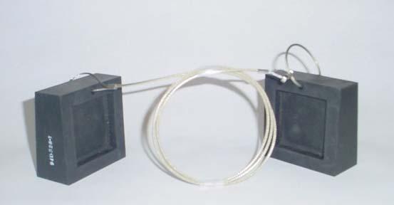
17 TM &P Title WP No./Page Figure 3. Rigging Shackle Assembly Figure 4. UH-1 Square Wedge Assembly Figure 5. Typical Cargo Hook Thimble Installation (Shown in Double-Eye Configuration) Figure 1. Damaged UH-1 and Recovery Helicopter Rigging Figure 2. Blade Sleeve Assembly Rigging and Installation Figure 3. UH-1 Square Wedge Assembly Figure 4. Rigging Shackle Assembly Figure 5. Typical Cargo Hook Thimble Installation (Shown in Double-Eye Configuration) CHAPTER 6 Figure 1. Preconfigure Green/White Slings Figure 2. Install Green/White Slings Figure 3. Installation of Sling Retention Assemblies Figure 4. Disabled UH-60 and Recovery Helicopter Rigging Figure 5. Rig Shackle Assembly Figure 6. Rigging Shackle Assembly Figure 7. Taping of Rigged Shackle Assembly Figure 8. Blade Sleeve Assembly Rigging and Installation Figure 1. Preconfigure Green/White Slings Figure 2. Install Green/White Slings Figure 3. Installation of Sling Retention Assemblies Figure 4. Disabled UH-60 and Recovery Helicopter Rigging Figure 5. Rig Shackle Assembly Figure 6. Rigging Shackle Assembly Figure 7. Taping of Rigged Shackle Assembly Figure 8. Blade Sleeve Assembly Rigging and Installation Figure 1. Preconfigure Green/White Slings...DELETED Figure 2. Install Green/White Slings...DELETED Figure 3. Installation of Sling Retention Assemblies...DELETED Figure 4. Disabled UH-60 and Recovery Helicopter Rigging...DELETED Figure 5. Rig Shackle Assembly...DELETED Figure 6. Rigging Shackle Assembly...DELETED Figure 7. Taping of Rigged Shackle Assembly...DELETED Figure 8. Blade Sleeve Assembly Rigging and Installation...DELETED Figure 9. Transitional Fairing (Doghouse)...DELETED Figure 1. Damaged UH-60 Rigging and Recovery Helicopter Rigging Figure 2. Blade Sleeve Assembly Rigging and Installation Figure 3. Rigging Shackle Assembly Figure 4. Typical Cargo Hook Thimble Installation (Shown in Double-Eye Configuration) Figure 1. Damaged UH-60 Rigging and Recovery Helicopter Rigging Figure 2. Blade Sleeve Assembly Rigging and Installation Figure 3. Rigging Shackle Assembly Figure 4. Typical Cargo Hook Thimble Installation (Shown in Double-Eye Configuration) CHAPTER 7 Figure 1. Sling Link Assembly Safety Wiring of Spring Lock Figure 2. UMARK Usage Tracking Form CHAPTER 8 Figure 1. Light Weight Slings (94D519-1, -2, -3, -4, 5) Figure 2. Heavy Weight Slings (94H520-1, 2) Figure 3. Adjustable Length Tie-Downs (94D521-1, -2) Figure 4. Ropes (94C522-1, -2) v
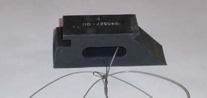
18 TM &P Title WP No./Page Figure 5. Blade Sleeves (94J516-1) Figure 6. Drogue Chute (1670EG029B3) Figure 7. Wedge Blocks (94D527-1, 94D528-1, 94D529-1, 94D530-1) Figure 8. Crossbar Assembly (94H501-1) Figure 9. Lifting Clevis Assembly (94D509-1) Figure 10. Shackle Assembly (94D514-1) Figure 11. Sling Link Assembly (94H523-1) Figure 12. Box Link Assembly (94C524-1) Figure 13. NBC Containers ( ) Figure 14. Blade Pole Assembly (94J531-1) Figure 15. Cargo Hook Thimble (94C533-1) vi
19 TM &P LIST OF TABLES Title WP No./Page CHAPTER 1 Table 1. Recovery Allowable Helicopters and Maximum Allowable Recovery Weights Table 2. UMARK Content List CHAPTER 2 Table 1. Recovery Helicopter Flight Parameters Table 2. UMARK Components Required Table 3. Disabled AH-1 and Recovery Helicopter Rigging - Key to Figure Table 1. Recovery Helicopter Flight Parameters Table 2. UMARK Components Required Table 3. Disabled AH-1 and Recovery Helicopter Rigging - Key to Figure Table 1. Recovery Helicopter Flight Parameters Table 2. UMARK Components Required Table 3. Damaged AH-1 and Recovery Helicopter Rigging - Key to Figure Table 1. Recovery Helicopter Flight Parameters Table 2. UMARK Components Required Table 3. Damaged AH-1 and Recovery Helicopter Rigging - Key to Figure CHAPTER 3 Table 1. Recovery Helicopter Flight Parameters Table 2. UMARK Components Required Table 3. Disabled AH-64A and Recovery Helicopter Rigging - Key to Figure Table 1. Recovery Helicopter Flight Parameters Table 2. UMARK Components Required Table 3. Disabled AH-64A and Recovery Helicopter Rigging - Key to Figure Table 1. Recovery Helicopter Flight Parameters...DELETED Table 2. UMARK Components Required...DELETED Table 3. Disabled AH-64A and Recovery Helicopter Rigging - Key to Figure 1...DELETED Table 1. Recovery Helicopter Flight Parameters Table 2. UMARK Components Required Table 3. Disabled AH-64D and Recovery Helicopter Rigging - Key to Figure Table 1. Recovery Helicopter Flight Parameters Table 2. UMARK Components Required Table 3. Disabled AH-64D and Recovery Helicopter Rigging - Key to Figure Table 1. Recovery Helicopter Flight Parameters...DELETED Table 2. UMARK Components Required...DELETED Table 3. Disabled AH-64D and Recovery Helicopter Rigging - Key to Figure 1...DELETED Table 1. Recovery Helicopter Flight Parameters Table 2. UMARK Components Required Table 3. Damaged AH-64A/D and Recovery Helicopter Rigging - Key to Figure CHAPTER 4 Table 1. Recovery Helicopter Flight Parameters Table 2. UMARK Components Required Table 3. Disabled OH-58A/C and Recovery Helicopter Rigging - Key to Figure Table 1. Recovery Helicopter Flight Parameters Table 2. UMARK Components Required vii
20 TM &P Title WP No./Page Table 3. Damaged OH-58A/C and Recovery Helicopter Rigging - Key to Figure Table 1. Recovery Helicopter Flight Parameters Table 2. UMARK Components Required Table 3. Damaged OH-58A/C and Recovery Helicopter Rigging - Key to Figure Table 1. Recovery Helicopter Flight Parameters Table 2. UMARK Components Required Table 3. Disabled OH-58D and Recovery Helicopter Rigging - Key to Figure Table 1. Recovery Helicopter Flight Parameters Table 2. UMARK Components Required Table 3. Damaged OH-58D and Recovery Helicopter Rigging - Key to Figure Table 1. Recovery Helicopter Flight Parameters Table 2. UMARK Components Required Table 3. Damaged OH-58D and Recovery Helicopter Rigging - Key to Figure CHAPTER 5 Table 1. Recovery Helicopter Flight Parameters Table 2. UMARK Components Required Table 3. Disabled UH-1 and Recovery Helicopter Rigging - Key to Figure Table 1. Recovery Helicopter Flight Parameters Table 2. UMARK Components Required Table 3. Disabled UH-1 and Recovery Helicopter Rigging - Key to Figure Table 1. Recovery Helicopter Flight Parameters Table 2. UMARK Components Required Table 3. Damaged UH-1 and Recovery Helicopter Rigging - Key to Figure CHAPTER 6 Table 1. Recovery Helicopter Flight Parameters Table 2. UMARK Components Required Table 3. Disabled UH-60 and Recovery Helicopter Rigging - Key to Figure Table 1. Recovery Helicopter Flight Parameters Table 2. UMARK Components Required Table 3. Disabled UH-60 and Recovery Helicopter Rigging - Key to Figure Table 1. Recovery Helicopter Flight Parameters...DELETED Table 2. UMARK Components Required...DELETED Table 3. Disabled UH-60 and Recovery Helicopter Rigging - Key to Figure 1...DELETED Table 1. Recovery Helicopter Flight Parameters Table 2. UMARK Components Required Table 3. Damaged UH-60 and Recovery Helicopter Rigging - Key to Figure Table 1. Recovery Helicopter Flight Parameters Table 2. UMARK Components Required Table 3. Damaged UH-60 and Recovery Helicopter Rigging - Key to Figure CHAPTER 7 Table 1. Preventative Maintenance Checks and Services Table 1. Source Code Definitions Table 2. Third Position Maintenance Code Definitions Table 3. Fourth Position Maintenance Code Definitions Table 4. Fifth Position Maintenance Code Definitions viii
21 TM &P HOW TO USE THIS MANUAL PURPOSE AND SCOPE This technical manual provides Aviation Unit (AVUM) usage and maintenance information for the Unit Maintenance Aerial Recovery Kit (UMARK). The information includes component and assembly description, usage instructions, maintenance and supporting data including a Repair Parts and Special Tools List (RPSTL) for identifying and ordering components, assemblies and repair parts. ARRANGEMENT, IDENTIFICATION AND LOCATION OF FRONT MATTER, REAR MATTER, CHAPTERS AND WORK PACKAGES This manual is composed of front matter, chapters containing work packages (WP s), and rear matter. Front Matter The front matter includes such items as the Warning Summary, List of Effective Pages/WP s, Table of Contents, and How to Use This Manual. Chapters and Work Packages The WP s contain information pertinent to the performance of specific tasks. Each WP is maintained as a separate entity. The WP s are grouped into Chapters based on overall content. WP s are arranged in numerical sequence regardless of chapter division. The chapter divisions and the WP s contained within the chapters are listed in the Table of Contents. Chapter 1 Introduction. This chapter provides general information about UMARK usage and descriptive information concerning the equipment within the kit. Chapter 2 AH-1 Recovery Procedures. This chapter contains individual work packages covering each of the possible recovery options for a disabled or damaged AH-1 helicopter. Chapter 3 AH-64 Recovery Procedures. This chapter contains individual work packages covering each of the possible recovery options for a disabled or damaged AH-64A and AH-64D helicopters. Chapter 4 OH-58 Recovery Procedures. This chapter contains individual work packages covering each of the possible recovery options for a disabled or damaged OH-58A/C or AH-58D helicopters. Chapter 5 UH-1 Recovery Procedures. This chapter contains individual work packages covering each of the possible recovery options for a disabled or damaged UH-1 helicopter. Chapter 6 UH-60 Recovery Procedures. This chapter contains individual work packages covering each of the possible recovery options for a disabled or damaged UH-60 helicopter. Chapter 7 Aviation Unit Maintenance Instructions. This chapter covers the preventative maintenance checks and services (PMCS) for the UMARK, including pre-usage and post-usage inspection requirements. Chapter 8 Supporting Information. This chapter provides information to support the maintenance actions in Chapter 7. Included are a list of reference material, the Maintenance Allocation Chart, which identifies maintenance actions and their maintenance levels, and the RPSTL. ix
22 TM &P HOW TO USE THIS MANUAL (Continued) Locating Work Packages There are two ways to locate a WP when the number is not known, using the Table of Contents in the manual s front matter and using the Index in the manual s rear matter. Locating a Work Package in the Table of Contents First determine the category of the WP subject and then find the appropriate chapter in the Table of Contents. Scan the WP titles in that chapter until you find the WP subject matter. In the example below, it is desired to locate the one-hook short-line recovery procedures for a disabled AH-1 helicopter (yellow highlight). The procedures fall into Chapter 1 AH-1 Recovery Procedures. Go to the Table of Contents and find the chapter titled AH-1 Recovery Procedures. Scan the WP titles within that chapter until you find the WP s titled Disabled AH-1, now scan these WP s for the One-Hook Short-Line statement and then follow the leader line to find the WP number. TABLE OF CONTENTS CHAPTER 1 INTRODUCTION WP No. CHAPTER 2 General Information AH-1 RECOVERY PROCEDURES Disabled AH-1 One-Hook Short-Line Recovery Procedures Disabled AH-1 One-Hook Long-Line Recovery Procedures Damaged AH-1 Main Rotor, Main Transmission, Main Mount Damage One-Hook Short-Line Recovery Procedures Damaged AH-1 Tail-Boom Damaged One-Hook Long-Line Recovery Procedures Locating a Work Package in the Index Look up the subject matter alphabetically in the Index. The index list each WP title as listed in the Table of Contents and at the title head of each work package, a variance of that work package title, and the WP s number to the right of the index title s leader line. The Index does not list individual paragraph contents of the work packages. In the example below, it is desired to locate the Disabled AH-1 One-Hook Long-Line Recovery Procedures (yellow highlight). Go to the index; find AH-1, next scan the title variances listed under AH-1, locate the One-Hook Long-Ling Recovery Procedure, Disabled title and follow the leader line to find the WP. This example list a variance of the WP titled Disabled AH-1 One-Hook Long-Line Recovery Procedures. ALPHABETICAL INDEX WP No. Alphabetical Index INDEX AH-1 Main Rotor, Main Transmission, Main Mount Damage One-Hook Short-Line Recovery Procedures, Damaged One-Hook Long-Line Recovery Procedures, Disabled One-Hook Short-Line Recovery Procedures, Disabled x
23 TM &P HOW TO USE THIS MANUAL (Continued) WORK PACKAGE CONTENT AND PRESENTATION The content and the presentation techniques used in the WP s vary according to the material content. The TM number and WP number are placed at the top of the page and are set of by horizontal lines as shown below. TM &P The page number is placed at the bottom of the page and consists of the WP number and a sequential number denoting the page within the WP as shown below Primary paragraph title heads are numbered to aid in cross-referencing (when necessary), and are in bolded upper case letters. Secondary level paragraphs are denoted by bolded headings set in Upper and Lower Case Type. These paragraphs always relate to and are subordinate to the most recent primary paragraph heading. Figures are titled, numbered, and listed in the table of contents under the chapter and WP they appear and if you follow the leader line the last digit is the page number of the WP where the figure is shown. Tables are titled, numbered, and listed in the table of contents under the chapter and WP they appear and if you follow the leader line the last digit is the page number of the WP where the table is shown. Manual Structure Chapter 1 contains the Introduction. This WP provides general information about the UMARK along with a detailed description of the UMARK components and assemblies. Chapter 2 contains multiple work packages covering established recovery procedures for the AH-1 helicopter. Chapter 3 contains multiple work packages covering established recovery procedures for the AH-64A and AH-64D helicopters. Chapter 4 contains multiple work packages covering established recovery procedures for the OH-58A/C and OH- 58D helicopters. Chapter 5 contains multiple work packages covering established recovery procedures for the UH-1 helicopter. Chapter 6 contains multiple work packages covering established recovery procedures for the UH-60 helicopter. Chapter 7 contains the AVUM Preventative Maintenance Checks and Services (PMCS) work package covering established PMCS procedures for pre-usage and post-usage inspections for the UMARK. Chapter 8 contains UMARK supporting information work packages covering the following: a. References b. Maintenance Allocations Chart c. Repair Parts and Special Tools (RPSTL) List d. Alphabetical Index xi/(xii blank)
24
25 CHAPTER 1 INTRODUCTION
26 TM &P _ GENERAL INFORMATION _ Index Scope... 1 Maintenance Forms, Records and Reports... 2 Reporting Equipment Improvement Recommendations (EIR)... 2 Destruction of Army Material to Prevent Enemy Use... 2 Preparation for Storage or Shipment... 2 List of Acronyms... 3 UMARK Component Description... 3 Light Weight Sling Assemblies... 4 Heavy Weight Sling Assemblies... 4 Adjustable Length Tie-Down Assemblies... 4 Sling Extensions... 4 Fixed Length Tie-Down Assemblies... 4 Blade Sleeve Assemblies... 4 Blade Pole Assembly UH-1 Square Wedges AH-1 and OH-58A/C Mast Wedges OH-58D Sight Wedge Box Link Assembly Sling Link Assembly Lifting Clevis Assembly Shackle Assembly Cargo Hook Thimble Crossbar Assembly Shipping Containers Drogue Chute Figures Figure 1. UMARK Components... 5 Tables Table 1. Recovery Allowable Helicopters and Maximum Allowable Recovery Weights... 2 _ Table 2. UMARK Content List SCOPE The unit maintenance aerial recovery kit (UMARK) is a system of slings, tie-downs, stabilizing equipment, and interconnecting hardware which can be assembled in multiple configurations to effect the safe aerial recovery of disabled or damaged helicopters. Helicopter damage may include, but is not limited to: a. The destruction of the main rotor head. b. The main rotor shaft or mast bent, broken, or loose in the transmission. c. The main transmission case cracked, broken, loose or separated from the airframe Change 3
27 TM &P _ d. Damage to the tail boom to such an extent that it is not suitable as a lifting point. e. Bending or buckling of the airframe so as to create aerodynamic instabilities that could result in additional damage during the recovery flight. f. Engines severely damaged or separated from the airframe. UMARK is designed to allow three ground personnel to rig a disabled or damaged helicopter for aerial recovery in less than 15 minutes. The disabled or damaged helicopters are not required to be stripped of components, defueled, disarmed, or have any additional maintenance actions performed on them prior to aerial recovery. UMARK can be installed under all environmental conditions, day or night (using artificial illumination or night vision equipment), by personnel wearing combat mission oriented protective posture (MOPP-4), or cold weather protective gear. It can be transported internally by the UH-1 helicopter or in a larger utility/cargo helicopter and transported on the ground by unit organic vehicles. Recovery helicopter models, disabled helicopter models, maximum allowable recovery weights, and eligible recovery helicopter hook-up configurations are listed in Table 1. Stated weights will vary with mission distance, weather conditions, and helicopter configuration. Table 1. Recovery Allowable Helicopter Model Applications and Maximum Allowable Recovery Weights Disabled Helicopter Maximum Recovered Weight Pounds Kilograms CH-47D Fwd & Aft Two-Hook 25,000 Lb. Max Lift CH-47D Center One-Hook 26,000 Lb. Max Lift CH-47D Fwd or Aft One-Hook 17,000 Lb. Max Lift UH-60A 8,000 Lb. Max Lift UH-60L 9,000 Lb. Max Lift UH-60M 10,000 Lb. Max Lift AH-1* 8,000 3,636 X X AH-64A 20,000 9,090 X AH-64D 20,000 9,090 X OH-58A/C 3,000 1,364 X X X X X OH-58D 5,500 2,500 X X X X X UH-1* 6,000 2,727 X X X X X UH-60 14,000 6,364 X X * All Army Models 2. MAINTENANCE FORMS, RECORDS AND REPORTS Department of the Army forms and procedures used for equipment maintenance are those prescribed by DA PAM , The Army Maintenance Management System Aviation (TAMMS-A)
28 TM &P _ 3. REPORTING EQUIPMENT IMPROVEMENT RECOMMENDATIONS (EIR) If you re UMARK needs improvement, let us know. Send us an EIR. You, the users are the only one who can tell us what you don t like about your equipment. Let us know why you don t like the design. Put it on SF368 (Quality Deficiency Report). Mail it to us at: We will send you a reply. Commander U.S. Army Aviation and Missile Command ATTN: AMSAM-MMC-MA-NM Redstone Arsenal, AL DESTRUCTION OF ARMY MATERIAL TO PREVENT ENEMY USE Procedures for destroying Army Material to prevent use are listed in TM PREPARATION FOR STORAGE OR SHIPMENT Refer to TM for preparation for storage and shipment. 6. LIST OF ACRONYMS See list immediately following: ACRONYM LIST MMA Mast-Mounted Assembly MMS Mast-Mounted Sight NBC Nuclear/Biological/Chemical UMARK Unit Maintenance Aerial Recovery Kit WP Work Package STA Station BL Bilge Line MAC Maintenance Allocation Chart PMCS Preventative Maintenance Checks and Services RPSTL Repair Parts and Special Tools List AVUM Aviation Unit Maintenance AVIM Aviation Intermediate Maintenance SMR Source, Maintenance and Recoverability UOC Usable On Code CAGE Commercial and Government-Entity EIR Equipment Improvement Recommendations
29 TM &P _ 7. UMARK COMPONENT DESCRIPTION (Figure 1 and Table 2) Table 2 lists all components contained in the UMARK. A discussion of each component is provided in the following paragraphs to familiarize the operator with the intended utilization of components. Table 2. UMARK Content List Figure 1 Sheet/ View Part Number Description Qty 8/X AL ELEC07 Shipping Containers 3 8/Y 1670EG029B3 Drogue Chute 1 2/J 94C522-1 Fixed Length Tiedown (with snaps) 4 2/K 94C522-2 Fixed Length Tiedown (without snaps) 1 5/Q 94C524-1 Box Link Assembly 3 6/V 94C533-1 Cargo Hook Thimble 1 6/T 94D509-1 Lifting Clevis Assembly 1 6/U 94D514-1 Shackle Assembly 1 1/A 94D519-1 Green/White Light Weight Sling 12.5 FT. (150 IN.) 4 1/B 94D519-2 Yellow/White Light Weight Sling FT. (153 IN.) 4 1/C 94D519-3 Red/White Light Weight Sling FT. (208 IN.) 2 1/D 94D519-4 Blue/ White Light Weight Sling 30 FT. (360 IN.) 2 1/E 94D519-5 Black/White Light Weight Sling 10 FT. (120 IN.) 1 4/P 94D527-1 OH-58D Sight Wedge 1 4/N 94D528-1 UH-1 Square Wedge 1 4/O 94D529-1 AH-1 MAST Wedge 1 4/O 94D530-1 OH-58 A/C MAST Wedge 1 7/W 94H501-1 Crossbar Assembly 1 1/F 94H520-1 Black/White Heavy Weight Sling 30 FT. (360 IN.) 2 1/G 94H520-2 Black/White Heavy Weight Sling (with bridle) 30 FT. (360 IN.) 1 2/H 94H521-1 Adjustable Length Tiedown Sling 2 2/I 94H521-2 Sling Extension 4 5/R & S 94H523-1 Sling Link Assembly 3 3/L 94J516-1 Blade Sleeve Assembly 4 3/M 94J531-1 Blade Pole Assembly
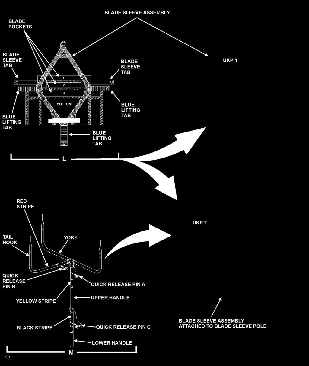
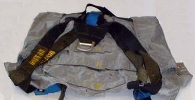
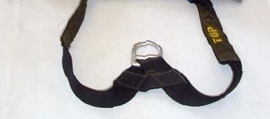
30 TM &P _ 8. Light Weight Sling Assemblies (Figure 1, Sheet 1, Views A through E) The light weight slings are constructed of synthetic braided materials. Two light weight sling configurations, in five color-coded lengths, are included in UMARK. All light weight slings are small diameter and equipped with a sling hook eye at each end. The bodies of the green/white slings (View A) are also equipped with a 25 inch long elastic cord which is used to maintain tension on the slings during OH-58D and AH-64 Longbow recovery operations with the crossbar assembly. 9. Heavy Weight Sling Assemblies (Views F and G) The heavy weight slings are constructed of synthetic braided materials. All three heavy weight slings included in UMARK are large diameter and color coded with black and white stripes. Each sling is 30 feet (360 inches) in length. The heavy weight slings are all equipped with two separated large diameter hook eyes on the top end (referred to at the double eye end) and one large diameter hook eye composed of two eyes lashed together on the bottom end (referred to at the single eye end). In addition to having the same large diameter hook eyes, one sling (View G) is also equipped with two bridle eyes approximately 7 feet (84 inches) from the top end. 10. Adjustable Length Tie-Down Assemblies (Sheet 2, View H) The adjustable tie-down assemblies included in UMARK are constructed of synthetic braided materials and are feet (477 inches) in length. The tie-downs function to secure the main rotor blades of the disabled/damaged helicopter. Each tie-down is equipped with a snap hook at each end, and ten sling hook eyes, five on each side of the tie-downs center line. The tie-down is attached to blade sleeve assemblies that have been attached to opposite main rotor blades, and the center point of the tie-down is attached to the shackle assembly at the primary lift point. Except for the AH-64D Longbow helicopter, adjustability is obtained by looping the tie-downs snap hook through the blade sleeve assembly top D-ring and hooking the snap hook to a specific snap hook eye on one of the five eyes on the snap hooks side of the tie-downs center line. The AH-64D uses the snap hooks only, without using the snap hook eyes. 11. Sling Extension (View I) The four sling extensions included in the UMARK are growth item for use with the RAH-66 helicopter. 12. Fixed Length Tie-Down Assemblies (Views J and K) The fixed length tie-down assemblies included in UMARK are constructed of synthetic braided material and are 40 feet (480 inches) in length. Two configurations are provided. Four of the tie-downs (View J) have a fused top end and a sling hook eye with attached snap hook at the bottom. A single tie-down (View K) has fused ends at both the top and bottom ends. 13. Blade Sleeve Assemblies (Sheet 3, View L) If the main rotor blades of a disabled helicopter are intact, the blades must be secured to prevent them from flexing during transportation. Excessive upward and downward deflection of the blades due to aerodynamic loading could result in damage to the blades and/or main rotor assembly. In addition, downward deflection of the disabled helicopter main rotor blades will limit airspeed of the recovery helicopter. Installation of blade sleeves with tie-downs will prevent the upward and downward deflection of the main rotor blades during transportation. The blade sleeve assembly included in UMARK is designed for multiple helicopter configurations and is constructed of fabric with attached straps and metal rings. Blade sleeve assembly pockets (1, 2, and 3) fit the following helicopter blades: a. Pocket 1 fits the OH-58A/C and OH-58D main rotor blades. b. Pocket 2 fits the AH-1, UH-1, AH-64A, AH-64D, and UH-60 main rotor blades. c. Pocket 3 is not currently used
31 TM &P _ Figure 1. UMARK Components (Sheet 1 of 8)
32 TM &P _ Figure 1. UMARK Components (Sheet 2)
33 TM &P _ Figure 1. UMARK Components (Sheet 3)

34 TM &P _ Figure 1. UMARK Components (Sheet 4)

35 TM &P _ Figure 1. UMARK Components (Sheet 5)


36 TM &P _ Figure 1. UMARK Components (Sheet 6)

37 TM &P _ Figure 1. UMARK Components (Sheet 7)
38 TM &P _ Figure 1. UMARK Components (Sheet 8)
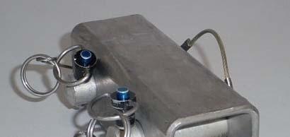
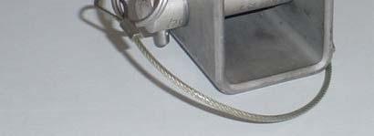
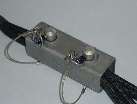
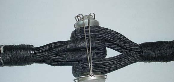
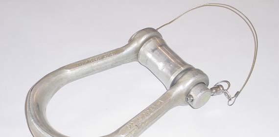
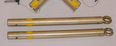
39 TM &P _ 14. Blade Pole Assembly (View M) The blade pole assembly is used to lift the blade sleeve assembly up to the blade of a disabled/damaged helicopter. The blade pole assembly is composed of four aluminum sections, a yoke, tail hook, and upper and lower handle sections. The attachment points of each section are color coded and secured with quick-disconnect pins. Assembly of the blade pole assembly is as follows: a. Insert the tail hook into the yoke, aligning the red stripes and quick-disconnect pinhole. Insert the quickdisconnect pin B. b. Insert the upper handle into the yoke, aligning the yellow stripes and quick-disconnect pinhole. Insert quickrelease pin A. c. Insert the lower handle into to upper handle, aligning the black stripes and quick-disconnect pinhole. Insert quick-release pin C. 15. UH-1 Square Wedges (Sheet 4,View N) The UH-1 square wedges are installed on the main rotor stops to prevent tilting of the main rotor during transportation of the disabled helicopter. The wedges are constructed of synthetic rubber. One wedge is equipped with a wire rope with a spring steel snap ring attached. The second wedge is equipped with a wire rope only. The snap ring and wire rope are used to position and secure the square wedges. 16. AH-1 and OH-58A/C Mast Wedges (View O) The AH-1 and OH-58 A/C mast wedges are circular silicone rubber tubes that are used to position and secure the disabled helicopter mast during transportation. Two sizes are included in UMARK. The large diameter mast wedge is used to secure the AH-1 mast and the small diameter mast wedge is used to secure the OH-58 A/C masts. Each mast wedge is equipped with a wire rope on one side and a spring steel snap ring attached with wire rope on the opposite side. The wire rope is passed over the top of the main rotor and attached to the snap ring on the opposite side. This secures the mast wedge to the mast and main rotor and prevents tilting of the main rotor during transportation. 17. OH-58D Sight Wedge (View P) The OH-58D sight wedge is used to stabilize the mast-mounted sight during transportation of the disabled helicopter and to stabilize the sight during assembly of the crossbar. The sight wedge is constructed of neoprene rubber. It is equipped with a lanyard and snap that is used to secure the sight wedge into position. 18. Box Link Assembly (Sheet 5, View Q) A box link assembly is used to connect two slings in series configuration. Components of a box link assembly include the box link housing, two box link pins, and two quick release pins. Two holes, corresponding to the diameter of the box link pins, are drilled on the top and bottom of the box link housing. The two box link pins and the two quick release pins are interconnected by wire rope. 19. Sling Link Assembly (Views R and S) A sling link assembly is used to connect slings. Components of the sling link assembly include a sling link pin with attached spring lock. Failure to arrange sling eyes on the sling link assembly as shown in Figure 1, Sheet 5, View S will create an unbalanced load on the sling link assembly and may cause the assembly to open as tension is applied to the slings. View R shows a safety wired joint that keeps the attached end of the sling link lock from separating from the sling link pin. Each recovery Work Package in the manual provides detailed instructions for the proper and safe use of the sling link assembly. These instructions shall be adhered to
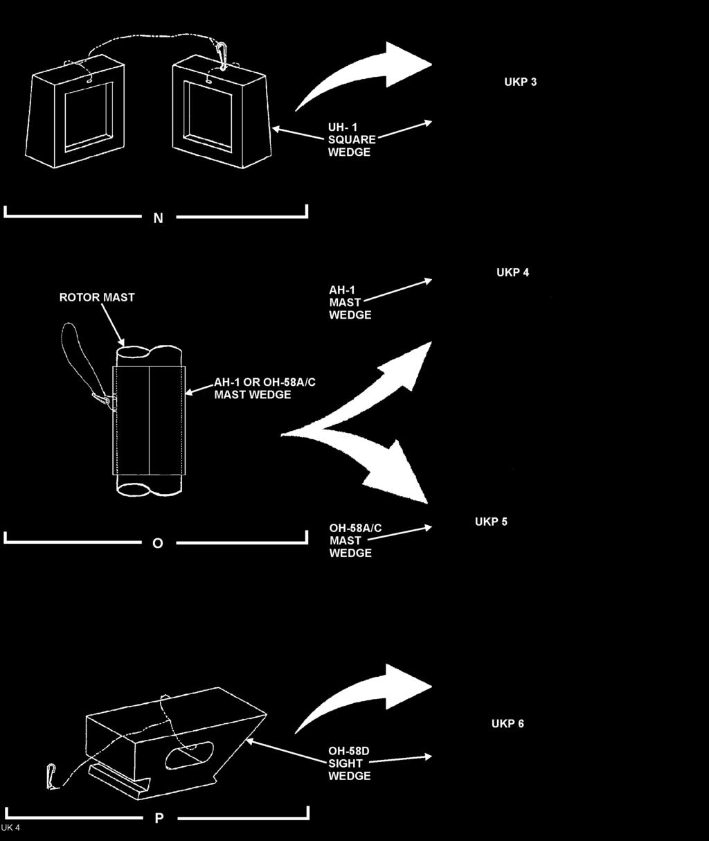
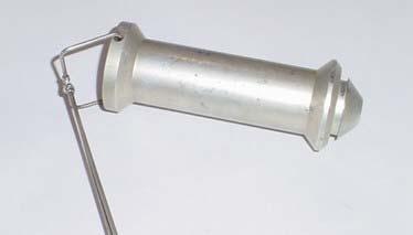
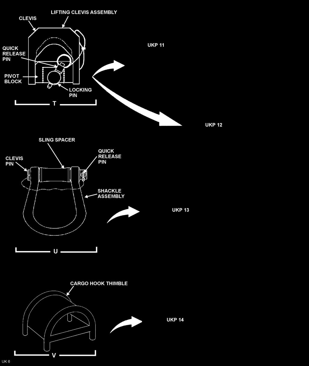
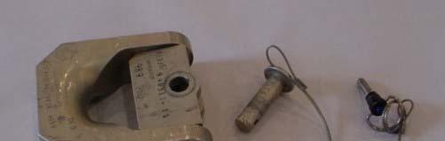
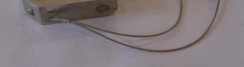
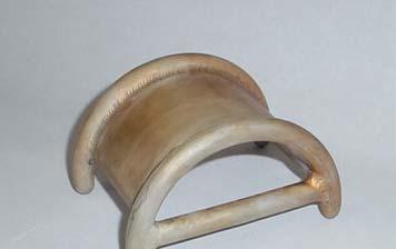
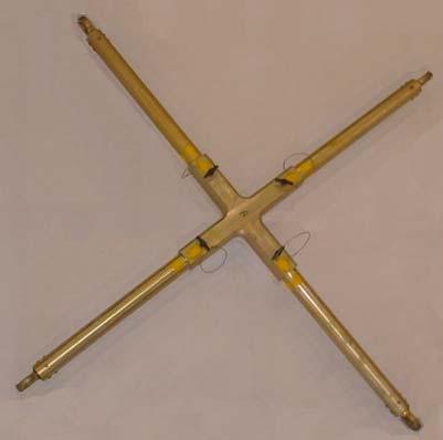
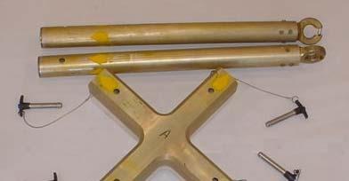
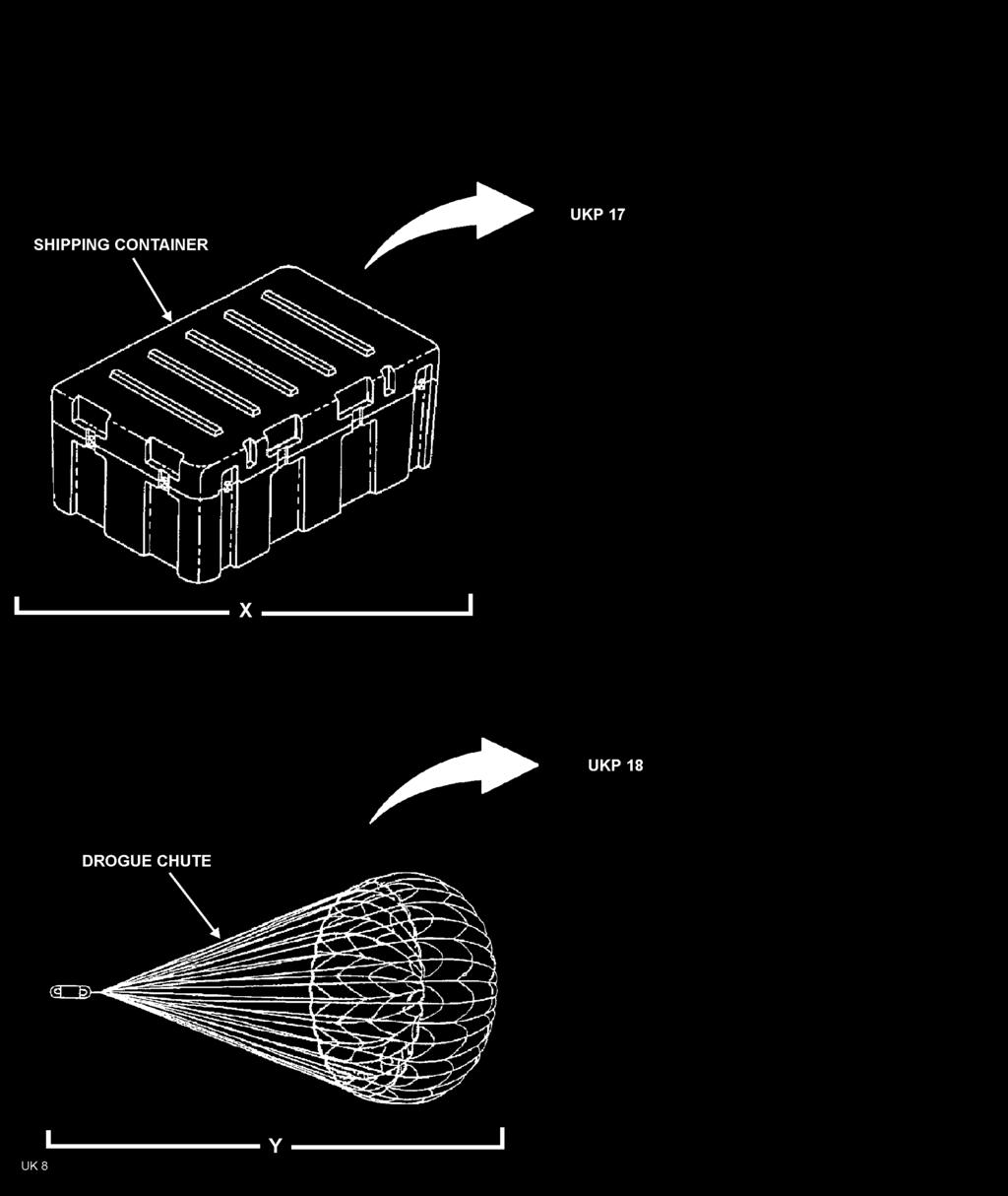
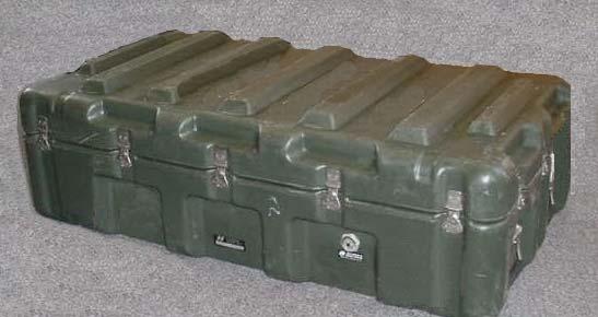
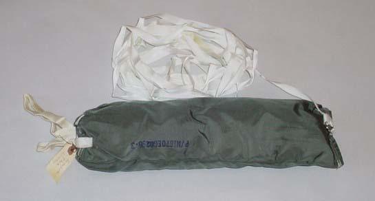
40 TM &P _ 20. Lifting Clevis Assembly (Sheet 6, View T) During AH-1, UH-1, and OH-58A and OH-58C helicopter recovery operations, the lifting clevis assembly replaces slings as the primary attachment devices to the main rotor assembly of the disabled helicopter. Components of the lifting clevis assembly include a clevis sub-assembly, a locking pin, and a quick release pin. The clevis sub-assembly consists of a clevis, two clevis pins, and a pivot block. The clevis pins are used to attach the clevis to the pivot block. The pivot block acts as a universal joint allowing movement in both fore-and-aft and side-to-side directions. The locking pin is used to attach the lifting clevis assembly to the helicopter hub nut lug. The quick release lock pin is used to secure the locking pin into position. Wire ropes are used to attach the locking pin and the quick release pin to the clevis sub-assembly. 21. Shackle Assembly (View U) The shackle assembly is used to connect two or three slings in a series-parallel configuration. Components of the shackle assembly include a clevis, a clevis pin, a sling spacer, and a quick release pin. The clevis pin and quick release pin are interconnected by wire rope. 22. Cargo Hook Thimble (View V) The cargo hook thimble is installed inside the eye of the heavy weight black/white sling that will be attached to the center cargo hook of a CH-47 recovery helicopter. The cargo hook thimble prevents the sling from riding forward on the hook. 23. Crossbar Assembly (Sheet 7, View W) The crossbar assembly is used to provide a load path around the AH-64D mast-mounted assembly (MMA) or the OH-58D mast-mounted sight (MMS). The crossbar assembly consists of a crossbar housing, four tube assemblies, and four quick release lock pins. The metal crossbar housing is X-shaped with four arms positioned 90-degrees apart. Each arm of the crossbar housing has a hole bored through the top and bottom surfaces. The bottom of the crossbar housing is fitted with a foam fitting which centers the crossbar housing on the MMA or MMS and protects it during transportation of the helicopter. The foam also allows for assembly of the crossbar on the antenna or sight. Each tube assembly is fitted with a sling lug fitting on the outboard end. The sling lug fitting is equipped with a spring lock. A hole is bored through the inboard end of each tube assembly. Quick release pins are used to connect the tube assemblies to the crossbar housing. 24. Shipping Containers (Sheet 8, View X) UMARK components are packaged in three watertight, nuclear/biological/chemical (NBC) contamination survivable containers. Each container is equipped with recessed latches, hinges, handgrips, and a pressure relief valve. Ribs molded into the top and bottom of each container interlock for stacking. When packed with UMARK equipment, two personnel using the recessed handgrips can carry each container. The handgrips can also be used as tie-down points during transportation. 25. Drogue Chute (View Y) The drogue chute may be deployed during recovery operations to maintain aerodynamic stability. The drogue chute must also be deployed when recovering any heavily damaged helicopter when either the vertical or horizontal stabilizer is broken off. END OF WORK PACKAGE /( blank)
41
42 CHAPTER 2 AH-1 RECOVERY PROCEDURES
43 TM &P DISABLED AH-1 ONE-HOOK SHORT-LINE RECOVERY PROCEDURES Index Introduction... 1 Pre-Recovery Procedures... 1 Recovery Flight Parameters and Precautions... 2 Components Required... 3 Disabled Helicopter Rigging... 3 Inspect Disabled Helicopter for Damage... 3 Install Main Rotor Rigging... 3 Install Tail-Boom Rigging Rig Recovery Helicopter Hook-Up and Recovery Flight Operations Post Recovery Kit Procedures Figures Figure 1. Disabled AH-1 and Recovery Helicopter Rigging... 4 Figure 2. Blade Sleeve Assembly Rigging and Installation... 7 Figure 3. Rigging Shackle Assembly... 9 Figure 4. AH-1 Mast Wedge Assembly Figure 5. Typical Cargo Hook Thimble Installation (Shown in Double-Eye Configuration) Tables Table 1. Recovery Helicopter Flight Parameters... 2 Table 2. UMARK Components Required... 3 Table 3. Disabled AH-1 and Recovery Helicopter Rigging - Key to Figure INTRODUCTION This Work Package (WP) covers the rigging of a disabled (not damaged) AH-1 using a one-hook short-line recovery procedure, the rigging of a CH-47 recovery helicopter, the recovery flight, and post recovery procedures. The short-line one-hook procedure provides for 60 feet of clearance between the recovery helicopter s single cargo hook in use and the shackle assembly that the disabled helicopter is rigged to. The ground rigging crew with the Unit Maintenance Aerial Recovery Kit (UMARK) can be deployed separately or with the recovery helicopter. The recovery process includes rigging the disabled helicopter, rigging the recovery helicopter, hooking up the recovery helicopter to the disabled helicopter, and having the recovery helicopter transport the disabled helicopter to a designated site. Refer to Work Package for general information concerning the UMARK function and component details. 2. PRE-RECOVERY PROCEDURES WARNING To prevent catastrophic failure do not use the UMARK if its record log indicates lifts in excess of 20 aerial lifts, 16 cumulative flight hours or 100 static lifts (crane/hoist). Ensure that a pre-usage inspection is performed on the UMARK contents as outlined in Work Package Do not use the UMARK kit if the kits usage log exceeds criteria listed in above Warning. Refer to Work Package for disposition instructions if the kit has exceeded criteria. Do not use the kit if any required content items fail pre-usage inspection Change 3
44 TM &P 3. RECOVERY FLIGHT PARAMETERS AND PRECAUTIONS Flight parameters for a CH-47 recovery helicopter are specified in Table 1. Table 1. Recovery Helicopter Flight Parameters Maximum Airspeed: Maximum Bank Angle: Maximum Rate-of-Climb Maximum Rate-of-Descent Drogue Chute 50 Knots Indicated Air Speed (KIAS) 25 Degrees 1250 Feet Per Minute (FPM) 2500 Feet Per Minute (FPM) Optional WARNING Once the disabled helicopter is connected to the recovery helicopter and lifted to a hover, the pitch attitude of the disabled helicopter must be checked to ensure a nose down attitude is achieved. A disabled helicopter may rotate while in a hover. This rotation may cause slings of some UMARK rigging configurations to twist or to tighten at the main rotor assembly. The rotation will generally stop as airspeed is increased to approximately 5 to 10 knots. The recovery helicopter flight crew should minimize hover time. If oscillations of disabled helicopter develop during flight, tests have shown that lowering airspeed, returning to wings level flight, and initiating a climb has a stabilizing effect. It is critical for the recovery helicopter flight crew to report any unusual occurrences. For example, vertical bounce, severe jerking of the disabled helicopter, hard landing of the disabled helicopter following recovery, UMARK component failure, or exceeding the flight parameters. Report any unusual occurrences to the unit responsible for the disabled helicopter. Exceeding the flight parameters may severely damage the main rotor assembly of the disabled helicopter, requiring component replacement. Report the amount and duration of any flight parameter exceeded to the unit responsible for the disabled helicopter. The height above ground level may be difficult to determine during low-level UMARK operations due to the length of the sling system. Flight crews should exercise extreme caution during recovery operations to ensure the disabled helicopter remains clear of ground obstacles
45 TM &P COMPONENTS REQUIRED Components of UMARK utilized during the one-hook, short-line recovery are listed in Table 2. Common equipment used by the ground rigging crew, such as shockproof gloves, goggles, radios, etc., are not included in UMARK. No additional tools are required for UMARK assembly or rigging of the helicopters. Table 2. UMARK Components Required Item Description Qty Item Description Qty Black/White 30 Ft Heavy Weight Sling 1 AH-1 Mast Wedge Assembly 1 Black/White 30 Ft Heavy Weight Sling with Bridle 1 Adjustable Length Tie-Down 1 Yellow/White 153 Inches (12.75 Ft) Light Weight Sling 2 Fixed Length Tie-Down (With Snap) 2 Red/White 208 Inches (17.33 Ft) Light Weight Sling 2 Fixed Length Tie-Down (Without Snap) 1 Blue/White 360 Inches (30.0 Ft) Light Weight Sling 2 Blade Sleeve Assemblies 2 Lifting Clevis Assembly 1 Blade Pole Assembly 1 Sling Link Assembly 2 Cargo Hook Thimble 1 Box Link Assembly 2 Drogue Chute 1 Shackle Assembly 1 5. DISABLED HELICOPTER RIGGING 6. Inspect Disabled Helicopter for Damage WARNING To prevent death or injury to personnel, and/or damage to the recovery and/or recovered helicopter, discontinue the disabled recovery procedure if damage is detected and refer to applicable Work Package of this manual as directed. a. Check the main rotor assembly, transmission and transmission mounts, and tail-boom for damage in accordance with applicable technical manual. (1) For damaged main rotor, main transmission, and/or transmission mounts perform damaged recovery procedure outlined in Work Package of this manual. (2) For damaged tail-boom perform damaged recovery procedure outlined in Work Package of this manual. 7. Install Main Rotor Rigging (Figures 1 and 2, and Table 3) NOTE Figure 1 details the disabled and recovery helicopter rigging. Reference numbers in the following text that are outlined in parentheses [i.e., (1), (2), etc.] refer to Figure 1, View A and Table 3 item numbers. Refer to Figure 1, View A and Table 3 for configuration guidance. a. Rotate the main rotor assembly to standard tie-down position. (Figure 1, View A)
46 TM &P Figure 1. Disabled AH-1 and Recovery Helicopter Rigging
47 TM &P Table 3. Disabled AH-1 and Recovery Helicopter Rigging Key to Figure 1 Figure 1 Item Description Item No. 1 Lifting Clevis Assembly 2 Yellow/White 153 Inches (12.75 Ft) Light Weight Sling 3 Red/White 208 inches (17.33 Ft) Light Weight Sling 4 Red/White 208 inches (17.33 Ft) Light Weight Sling 5 Shackle Assembly 6 Black/White 30 Ft Heavy Weight Sling with Bridle 7 Blue/White 360 inches (30.0 Ft) Light Weight Sling 8 Sling Link Assembly 9 Box Link Assembly 10 Yellow/White 153 Inches (12.75 Ft) Light Weight Sling 11 Box Link Assembly 12 Blue/White 360 inches (30.0 Ft) Light Weight Sling 13 AH-1 Mast Wedge Assembly 14 Black/White 30 Ft Heavy Weight Sling 15 Sling Link Assembly 16 Cargo Hook Thimble b. Install the lifting clevis assembly (1), View A onto the AH-1 lifting lug (View B) as follows: NOTE The lifting clevis assembly (View B) is attached to the AH-1 lifting lug that is located on the main rotor mast, above the plane of the main rotor blades. The lifting clevis assembly will then be attached to slings allowing the AH-1 to be lifted by the recovery helicopter. (1) Remove the quick-release pin from the locking pin, and then remove the locking pin from the lifting clevis assembly. (2) Place the lifting clevis assembly onto the AH-1 lifting lug so that the recess in the pivot block covers the AH-1 lifting lug. (3) Align the holes between the lifting clevis assembly pivot block and the AH-1 lifting lug. (4) Install the locking pin through the pivot block and the lifting lug, and install the quick-release pin into the locking pin. c. Pass one sling eye of the yellow/white sling (2), View A, between the lifting clevis assembly s clevis and pivot block (View B). (1) Carefully lay the sling eyes for yellow/white sling (2) on the helicopter for easy access during the shackle assembly hook-up in step i. of the Paragraph
48 TM &P d. Install two red/white slings (3 and 4), View A, for use as back-up slings as follows: (1) Position the mid-point of a red/white sling (3) over the forward main rotor blade retention assembly adjacent to the main rotor mast. (2) Loop the red/white sling (3) under the forward main rotor yoke assembly (View C). CAUTION Ensure that the red/white sling (3 or 4) does not cross itself at any point. (3) Bring the red/white sling (3) eyes together, and set aside. (4) Repeat steps (1) through (3) above for installation of the aft red/white sling (4). (5) Carefully lay both red/white sling eyes (3 and 4) on the helicopter for easy access during the shackle assembly hook-up in step f. of this Paragraph. e. Rig and install blade sleeve assemblies as follows: (Figure 2) NOTE Blade sleeve assemblies are attached to each main rotor blade. An adjustable length tie-down is attached between the sleeve assemblies top D-rings and attached to the shackle assembly during the recovery hook-up procedure. A fixed length tie-down is attached to the bottom D-ring of each blade sleeve assembly and secured to an appropriate airframe hard point to secure the main rotor blades during the recovery flight. (1) Orient the blade sleeve assembly (View A) so that the markings saying TOP on both the blade sleeve bag and straps are facing down. (2) Fold both left and right edges of the blade sleeve bag inward until the matching loop/hook closures are engaged. (3) Assemble the blade sleeve pole. (View B) (4) Open bag pocket number two on the blade sleeve bag (View A) by separating the loop/hook closures. (5) With one hand, take hold of blade sleeve bags left side blade sleeve tab and left side blue lifting tab. (6) With other hand, take hold of blade sleeve bags right side blade sleeve tab and right side blue lifting tab. (7) Rotate the blade sleeve assembly so that the TOP markings are now facing up. (8) Orient the blade sleeve open bag pocket so that it is facing away from the operator holding the lifting tabs. (9) Place the blade sleeve assembly lifting tabs from the bag and strap that are held in the left hand onto Position 1 of the blade sleeve pole. (View B)
49 TM &P Figure 2. Blade Sleeve Assembly Rigging and Installation
50 TM &P (10) Place the blade sleeve assembly lifting tabs being held in the right hand onto Position 2 of the blade sleeve pole. (11) Place the remaining blue colored lifting tab on the lower edge of the blade sleeve assembly strap onto Position 3 of the blade sleeve pole. (12) Verify that the appropriate blade sleeve assembly bag pocket is still open, and all the other bag pockets are still closed. (13) Pass the snap hook from one end of the adjustable length tie-down sling through the D-ring on the blade sleeve assembly straps marked TOP and secure snap hook to loop position 4 on the adjustable length tie-down. (View C) (14) Connect the snap hook from the fixed length tie-down sling to the D-ring on the blade sleeve assembly straps marked BOTTOM. (15) The blade sleeve assembly is now ready for installation onto the rotor blade. (16) Lift up the blade sleeve assembly with the blade sleeve pole and slide the open blade sleeve assembly bag pocket over the forward pointing rotor blade, while a second person leads the adjustable length tie-down and fixed length tie-down along the rotor blade. CAUTION To prevent possible damage to the main rotor system assembly fixed length tie-downs must be secured with approximately 18 inches of slack in the lines. (17) Leaving approximately 18 inches of slack, secure the fixed-length tie-down to the appropriate area of the airframe. (18) Using the unattached end of the adjustable length tie-down already installed repeat steps (1) through (17) for the opposite facing rotor. (19) Carefully orient the middle of the adjustable length tie-down sling near the main rotor mast for easy access during the shackle assembly hook-up in step f. of this Paragraph. f. Rig Shackle Assembly (Figures 1 and 3) NOTE During shackle assembly rigging and subsequent recovery flight all light weight slings and tie-downs attached to the main rotor blades are to be attached to the clevis part of the shackle assembly, while the heavy weight black/white sling is on the shackle assemblies sling spacer (1) Remove quick-release pin, clevis pin and sling spacer from shackle assembly clevis. (5, Figure 1 and Figure 3) (2) Install both sling eyes from the forward red/white safety slings onto the clevis part of the shackle assembly. (3) Install the two sling eyes from the yellow/white sling that is attached to the lifting clevis on the disabled helicopter main rotor onto the clevis part of the shackle assembly
51 TM &P Figure 3. Rigging Shackle Assembly (4) Install both sling eyes from aft red/white safety slings onto clevis part of the shackle assembly. (5) Place the midpoint of the adjustable length tie-down sling attached to the topside of the blade sleeves through the clevis part of the shackle assembly. CAUTION Ensure that the sling spacer is installed when the shackle assembly is assembled. (6) Place the single eye end of heavy weight black/white sling with bridle (6), Figure 1, View A, to the shackle assembly (Figure 3) and secure shackle assembly as follows: (a) Insert sling spacer from shackle assembly into the sling eye end opening of heavy weight black/white sling. (b) Align the holes in the shackle assembly clevis with the hole in the sling spacer. (c) Once holes are aligned, insert the clevis pin through the holes in the shackle assembly clevis assembly and sling spacer. (d) Insert quick-release pin through hole in base of the clevis pin to secure the clevis pin in the clevis. (7) Carefully lay the rigged shackle assembly on the helicopter and heavy weight sling (6), Figure 1, View A, to the side that the recovery helicopter will approach from for easy access during the recovery helicopter hook-up procedure covered in Paragraph 10 of this WP
52 TM &P 8. Install Tail-Boom Rigging (Figure 1 and Table 3) a. Fold blue/white sling (7) in half. (View A) b. Place the two sling eyes of folded blue/white sling (7) in-between the sling (6) bridle loops. WARNING Failure to arrange sling eyes on the sling link assembly as shown in Figure 1, View E, will create an unbalanced load on the sling link assembly and may cause the assembly to open as tension is applied to the slings. (1) Connect sling link assembly (8) through sling eyes of sling (7) and through bridle loops of sling (6). (2) Verify that arrangement of sling eyes is as shown in View E, with sling (6) bridle loops in the Position A orientation. c. Connect box link assembly (9), View A, at the mid-point fold of blue/white sling (7). (1) Secure sling (7) to box link using box link pin and quick-disconnect pin. (View F) d. Connect one sling eye of yellow/white sling (10), View A, to the other end of box link assembly (9) installed on folded sling (7). (1) Secure sling (10) to box link using box link pin and quick-disconnect pin. (View F) e. Connect a second box link assembly (11), View A, to the other sling eye of sling (10). (1) Secure sling (10) to box link using box link pin and quick-disconnect pin. (View F) f. Connect the blue/white sling (12), View A, around the disabled helicopter tail section as follows: (1) Locate the position on helicopter tail-section that approximately in the location of the intermediate gearbox and loop the blue/white sling around this point. (View G) (2) Connect both eyes of blue/white sling (12) to box link (11). (View A) (3) Secure sling (12) to box link using box link pin and quick-disconnect pin. (View F) g. To prevent tail rotor blade flapping tie the lower blade from the tail rotor to the helicopter using a fixed length tie-down (without snap hook). h. Drogue Chute Installation NOTE As determined by ground crew, a drogue chute may be attached to the disabled helicopter to facilitate stable flight. (1) Secure drogue chute to the tail end of tail-boom. Do not deploy drogue chute until recovery helicopter has hovered over disabled or damaged helicopter. i. Install the AH-1 mast wedge assembly (13) in accordance with Figure 1, View A location, and Figure 4, as follows: NOTE UMARK contains two similar mast wedge assemblies for different helicopters. Refer to WP of this manual and verify that correct mast wedge assembly is in use. (1) Open the mast wedge (Figure 4) rubber tube section along the centerline seam and install the rubber tube section around the main rotor mast near the bottom of the main rotor hub assembly
53 TM &P Figure 4. AH-1 Mast Wedge Assembly NOTE When installing wedge assembly it may be necessary to slightly rock blades using fixed length tie-downs attached to blade sleeve assemblies to place wedge assembly in correct location. (2) Carefully slide the tube up into the gap between the main rotor hub and the main rotor mast. (3) Verify that stops on the main rotor hub fully contact mast wedge assembly and not main rotor mast. (4) Loop lanyard attached to mast wedge assembly around main rotor hub and secure snap back onto lanyard. Lanyard is designed to prevent mast wedge assembly from sliding down and exposing main rotor assembly. j. The disabled helicopter is now ready for hookup to the recovery helicopter. 9. RIG RECOVERY HELICOPTER (Figures 1 and 5, and Table 3) NOTE Figure 1 details the disabled and recovery helicopter rigging. Reference numbers in the following text that are outlined in parentheses [i.e., (1), (2), etc.] refer to Figure 1, View A and Table 3 item numbers. Refer to Figure 1, View A and Table 3 for configuration guidance. a. Place a cargo hook thimble (16, Figure 1, View A, and Figure 5) into the double eye end of heavy weight black/white sling (14). b. Connect the double eye end of heavy weight black/white sling (14, Figure 1, View A) with the hook thimble installed, to the recovery helicopter center cargo hook. c. Pull free end of heavy weight black/white sling through center cargo hook hole and secure until helicopter being recovered is ready for hook-up
54 TM &P Figure 5. Typical Cargo Hook Thimble Installation (Shown in Double-Eye Configuration) 10. HOOK-UP AND RECOVERY FLIGHT OPERATIONS (Figure 1 and Table 3) WARNING Should it become necessary for a ground crew member to perform hook-up while on the helicopter being recovered, extreme care must be exercised to avoid static electric shock, injury resulting from falling off the helicopter as a result of rotor downwash, etc. a. Launch recovery helicopter. CAUTION Remove any loose objects from recovery site to prevent them from becoming projectiles as a result of rotor downwash. NOTE Figure 1 details the disabled and recovery helicopter rigging. Reference numbers in the following text that are outlined in parentheses [i.e., (1), (2), etc.] refer to Figure 1, View A and Table 3 item numbers. Refer to Figure 1, View A and Table 3 for configuration guidance. b. Direct recovery helicopter into hover position slightly to the side of the disabled helicopter where sling (6), Figure 1, View A, has been positioned for connection of the disabled helicopter to the recovery helicopter sling
55 TM &P WARNING Ensure static grounding of recovery helicopter is accomplished by allowing free end of sling lines to touch the ground before ground crew comes in contact with sling. CAUTION Once sling line has come in contact with ground and after sling line comes in contact with a ground crew member, the crewmember must maintain continuous contact with the sling line until it is connected to the disabled helicopter to maintain static grounding. c. Allow end of sling line from recovery helicopter to make ground contact to discharge static electricity. WARNING Failure to arrange sling eyes on the sling link assembly as shown in Figure 1, View E will create an unbalanced load on the sling link assembly and may cause the assembly to open as tension is applied to the slings. d. Connect the double eye end of heavy weight black/white sling (6), Figure 1, View A, (connected to the disabled helicopter) to the single eye end of heavy weight black/white sling (14) (connected to the recovery helicopter) using sling link assembly (15). (1) Verify that arrangement of sling eyes is as shown in View E, with sling (6) in the Position A orientation. e. Deploy the drogue chute if installed. f. Direct recovery helicopter to place tension on the slings while the ground crew guides the slings to prevent entanglement with the disabled helicopter. g. Evacuate ground crew from rigging site. h. Direct recovery helicopter to take-off with the disabled helicopter connected. 11. POST RECOVERY KIT PROCEDURES Upon reaching the destination with the disabled helicopter, the recovery helicopter must come to a hover with the disabled helicopter a few feet off the ground. It is important that hover time be kept to a minimum to prevent spinning of the disabled helicopter. After the disabled helicopter has been lowered to the ground, the recovery helicopter should be directed to a point where the slings can be released without damaging either helicopter
56 TM &P After an aerial recovery mission has been completed, the UMARK components must be returned to a ready-forissue (RFI) condition. a. Ensure kits usage log is updated to indicate this events use. If this event use is the unit s 20 th usage refer to Work Package for disposition of kit. Kit must be returned to depot maintenance for evaluation. b. All UMARK equipment shall be cleaned, dried, inspected, and replaced, if necessary, in accordance with Work Package Following post recovery component maintenance all UMARK components shall be repacked into the UMARK containers in a neat and orderly fashion. The UMARK containers should then be secured and stored for the next aerial recovery mission. END OF WORK PACKAGE
57 TM &P DISABLED AH-1 ONE-HOOK LONG-LINE RECOVERY PROCEDURES Index Introduction... 1 Pre-Recovery Procedures... 1 Recovery Flight Parameters and Precautions... 2 Components Required... 3 Disabled Helicopter Rigging... 3 Inspect Disabled Helicopter for Damage... 3 Install Main Rotor Rigging... 3 Install Tail-Boom Rigging Rig Recovery Helicopter Hook-Up and Recovery Flight Operations Post Recovery Kit Procedures Figures Figure 1. Disabled AH-1 and Recovery Helicopter Rigging... 4 Figure 2. Blade Sleeve Assembly Rigging and Installation... 7 Figure 3. Rigging Shackle Assembly... 9 Figure 4. AH-1 Mast Wedge Assembly Figure 5. Typical Cargo Hook Thimble Installation (Shown in Double-Eye Configuration) Tables Table 1. Recovery Helicopter Flight Parameters... 2 Table 2. UMARK Components Required... 3 Table 3. Disabled AH-1 and Recovery Helicopter Rigging - Key to Figure INTRODUCTION This Work Package (WP) covers the rigging of a disabled (not damaged) AH-1 using a one-hook long-line recovery procedure, the rigging of a CH-47 recovery helicopter, the recovery flight, and post recovery procedures. The long-line one-hook procedure provides for 90 feet of clearance between the recovery helicopter s single cargo hook in use and the shackle assembly that the disabled helicopter is rigged to. The ground rigging crew with the Unit Maintenance Aerial Recovery Kit (UMARK) can be deployed separately or with the recovery helicopter. The recovery process includes rigging the disabled helicopter, rigging the recovery helicopter, hooking up the recovery helicopter to the disabled helicopter, and having the recovery helicopter transport the disabled helicopter to a designated site. Refer to Work Package for general information concerning the UMARK function and component details. 2. PRE-RECOVERY PROCEDURES WARNING To prevent catastrophic failure do not use the UMARK if its record log indicates lifts in excess of 20 aerial lifts, 16 cumulative flight hours or 100 static lifts (crane/hoist). Ensure that a pre-usage inspection is performed on the UMARK contents as outlined in Work Package Do not use the UMARK kit if the kits usage log exceeds criteria listed in above Warning. Refer to Work Package for disposition instructions if the kit has exceeded criteria. Do not use the kit if any required content items fail pre-usage inspection Change 3
58 TM &P 3. RECOVERY FLIGHT PARAMETERS AND PRECAUTIONS Flight parameters for a CH-47 recovery helicopter are specified in Table 1. Table 1. Recovery Helicopter Flight Parameters Maximum Airspeed: Maximum Bank Angle: Maximum Rate-of-Climb Maximum Rate-of-Descent Drogue Chute 50 Knots Indicated Air Speed (KIAS) 25 Degrees 1250 Feet Per Minute (FPM) 2500 Feet Per Minute (FPM) Optional WARNING Once the disabled helicopter is connected to the recovery helicopter and lifted to a hover, the pitch attitude of the disabled helicopter must be checked to ensure a nose down attitude is achieved. A disabled helicopter may rotate while in a hover. This rotation may cause slings of some UMARK rigging configurations to twist or to tighten at the main rotor assembly. The rotation will generally stop as airspeed is increased to approximately 5 to 10 knots. The recovery helicopter flight crew should minimize hover time. If oscillations of disabled helicopter develop during flight, tests have shown that lowering airspeed, returning to wings level flight, and initiating a climb has a stabilizing effect. It is critical for the recovery helicopter flight crew to report any unusual occurrences. For example, vertical bounce, severe jerking of the disabled helicopter, hard landing of the disabled helicopter following recovery, UMARK component failure, or exceeding the flight parameters. Report any unusual occurrences to the unit responsible for the disabled helicopter. Exceeding the flight parameters may severely damage the main rotor assembly of the disabled helicopter, requiring component replacement. Report the amount and duration of any flight parameter exceeded to the unit responsible for the disabled helicopter. The height above ground level may be difficult to determine during low-level UMARK operations due to the length of the sling system. Flight crews should exercise extreme caution during recovery operations to ensure the disabled helicopter remains clear of ground obstacles
59 TM &P COMPONENTS REQUIRED Components of UMARK utilized during the one-hook, long-line recovery are listed in Table 2. Common equipment used by the ground rigging crew, such as shockproof gloves, goggles, radios, etc., are not included in UMARK. No additional tools are required for UMARK assembly or rigging of the helicopters. Table 2. UMARK Components Required Item Description Qty Item Description Qty Black/White 30 Ft Heavy Weight Sling 2 AH-1 Mast Wedge Assembly 1 Black/White 30 Ft Heavy Weight Sling with Bridle 1 Adjustable Length Tie-Down 1 Yellow/White 153 Inches (12.75 Ft) Light Weight Sling 2 Fixed Length Tie-Down (With Snap) 2 Red/White 208 Inches (17.33 Ft) Light Weight Sling 2 Fixed Length Tie-Down (Without Snap) 1 Blue/White 360 Inches (30.0 Ft) Light Weight Sling 2 Blade Sleeve Assemblies 2 Lifting Clevis Assembly 1 Blade Pole Assembly 1 Sling Link Assembly 3 Cargo Hook Thimble 1 Box Link Assembly 2 Drogue Chute 1 Shackle Assembly 1 5. DISABLED HELICOPTER RIGGING 6. Inspect Disabled Helicopter for Damage WARNING To prevent death or injury to personnel, and/or damage to the recovery and/or recovered helicopter, discontinue the disabled recovery procedure if damage is detected and refer to applicable Work Package of this manual as directed. a. Check the main rotor assembly, transmission and transmission mounts, and tail-boom for damage in accordance with applicable technical manual. (1) For damaged main rotor, main transmission, and/or transmission mounts perform damaged recovery procedure outlined in Work Package of this manual. (2) For damaged tail-boom perform damaged recovery procedure outlined in Work Package of this manual. b. If no damage is detected in the preceding step proceed to the next step. 7. Install Main Rotor Rigging (Figures 1 and 2, and Table 3) NOTE Figure 1 details the disabled and recovery helicopter rigging. Reference numbers in the following text that are outlined in parentheses [i.e., (1), (2), etc.] refer to Figure 1, View A and Table 3 item numbers. Refer to Figure 1, View A and Table 3 for configuration guidance. a. Rotate the main rotor assembly to standard tie-down position. (Figure 1, View A)

60 TM &P Figure 1. Disabled AH-1 and Recovery Helicopter Rigging
61 TM &P Table 3. Disabled AH-1 and Recovery Helicopter Rigging Key to Figure 1 Figure 1 Item Description Item No. 1 Lifting Clevis Assembly 2 Yellow/White 153 Inches (12.75 Ft) Light Weight Sling 3 Red/White 208 inches (17.33 Ft) Light Weight Sling 4 Red/White 208 inches (17.33 Ft) Light Weight Sling 5 Shackle Assembly 6 Black/White 30 Ft Heavy Weight Sling with Bridle 7 Sling Link Assembly 8 Black/White 30 Ft Heavy Weight Sling 9 Blue/White 360 inches (30.0 Ft) Light Weight Sling 10 Sling Link Assembly 11 Box Link Assembly 12 Yellow/White 153 Inches (12.75 Ft) Light Weight Sling 13 Box Link Assembly 14 Blue/White 360 inches (30.0 Ft) Light Weight Sling 15 AH-1 Mast Wedge Assembly 16 Black/White 30 Ft Heavy Weight Sling 17 Sling Link Assembly 18 Cargo Hook Thimble b. Install the lifting clevis assembly (1), View A onto the AH-1 lifting lug (View B) as follows: NOTE The lifting clevis assembly (View B) is attached to the AH-1 lifting lug that is located on the main rotor mast, above the plane of the main rotor blades. The lifting clevis assembly will then be attached to slings allowing the AH-1 to be lifted by the recovery helicopter. (1) Remove the quick-release pin from the locking pin, and then remove the locking pin from the lifting clevis assembly. (2) Place the lifting clevis assembly onto the AH-1 lifting lug so that the recess in the pivot block covers the AH-1 lifting lug. (3) Align the holes between the lifting clevis assembly pivot block and the AH-1 lifting lug. (4) Install the locking pin through the pivot block and the lifting lug, and install the quick-release pin into the locking pin. c. Pass one sling eye of the yellow/white sling (2), View A, between the lifting clevis assembly s clevis and pivot block (View B). (1) Carefully lay the sling eyes for yellow/white sling (2) on the helicopter for easy access during the shackle assembly hook-up in step i. of the Paragraph
62 TM &P d. Install two red/white slings (3 and 4), View A, for use as back-up slings as follows: (1) Position the mid-point of a red/white sling (3) over the forward main rotor blade retention assembly adjacent to the main rotor mast. (2) Loop the red/white sling (3) under the forward main rotor yoke assembly (View C). CAUTION Ensure that the red/white sling (3 or 4) does not cross itself at any point. (3) Bring the red/white sling (3) eyes together, and set aside. (4) Repeat steps (1) through (3) above for installation of the aft red/white sling (4). (5) Carefully lay both red/white sling eyes (3 and 4) on the helicopter for easy access during the shackle assembly hook-up in step f. of this Paragraph. e. Rig and install blade sleeve assemblies as follows: (Figure 2) NOTE Blade sleeve assemblies are attached to each main rotor blade. An adjustable length tie-down is attached between the sleeve assemblies top D-rings and attached to the shackle assembly during the recovery hook-up procedure. A fixed length tie-down is attached to the bottom D-ring of each blade sleeve assembly and secured to an appropriate airframe hard point to secure the main rotor blades during the recovery flight. (1) Orient the blade sleeve assembly (View A) so that the markings saying TOP on both the blade sleeve bag and straps are facing down. (2) Fold both left and right edges of the blade sleeve bag inward until the matching loop/hook closures are engaged. (3) Assemble the blade sleeve pole. (View B) (4) Open bag pocket number two on the blade sleeve bag (View A) by separating the loop/hook closures. (5) With one hand, take hold of blade sleeve bags left side blade sleeve tab and left side blue lifting tab. (6) With other hand, take hold of blade sleeve bags right side blade sleeve tab and right side blue lifting tab. (7) Rotate the blade sleeve assembly so that the TOP markings are now facing up. (8) Orient the blade sleeve open bag pocket so that it is facing away from the operator holding the lifting tabs. (9) Place the blade sleeve assembly lifting tabs from the bag and strap that are held in the left hand onto Position 1 of the blade sleeve pole. (View B)
63 TM &P Figure 2. Blade Sleeve Assembly Rigging and Installation
64 TM &P (10) Place the blade sleeve assembly lifting tabs being held in the right hand onto Position 2 of the blade sleeve pole. (11) Place the remaining blue colored lifting tab on the lower edge of the blade sleeve assembly strap onto Position 3 of the blade sleeve pole. (12) Verify that the appropriate blade sleeve assembly bag pocket is still open, and all the other bag pockets are still closed. (13) Pass the snap hook from one end of the adjustable length tie-down sling through the D-ring on the blade sleeve assembly straps marked TOP and secure snap hook to loop position 4 on the adjustable length tie-down. (View C) (14) Connect the snap hook from the fixed length tie-down sling to the D-ring on the blade sleeve assembly straps marked BOTTOM. (15) The blade sleeve assembly is now ready for installation onto the rotor blade. (16) Lift up the blade sleeve assembly with the blade sleeve pole and slide the open blade sleeve assembly bag pocket over the forward pointing rotor blade, while a second person leads the adjustable length tie-down and fixed length tie-down along the rotor blade. CAUTION To prevent possible damage to the main rotor system assembly fixed length tie-downs must be secured with approximately 18 inches of slack in the lines. (17) Leaving approximately 18 inches of slack, secure the fixed-length tie-down to the appropriate area of the airframe. (18) Using the unattached end of the adjustable length tie-down already installed repeat steps (1) through (17) for the opposite facing rotor. (19) Carefully orient the middle of the adjustable length tie-down sling near the main rotor mast for easy access during the shackle assembly hook-up covered in step f. of this Paragraph. f. Rig Shackle Assembly (Figures 1 and 3) NOTE During shackle assembly rigging and subsequent recovery flight all light weight slings and tie-downs attached to the main rotor blades are to be attached to the clevis part of the shackle assembly, while the heavy weight black/white sling is on the shackle assemblies sling spacer (1) Remove quick-release pin, clevis pin and sling spacer from shackle assembly clevis. (5, Figure 1 and Figure 3) (2) Install both sling eyes from the forward red/white safety slings onto the clevis part of the shackle assembly. (3) Install the two sling eyes from the yellow/white sling that is attached to the lifting clevis on the disabled helicopter main rotor onto the clevis part of the shackle assembly
65 TM &P Figure 3. Rigging Shackle Assembly (4) Install both sling eyes from aft red/white safety slings onto clevis part of the shackle assembly. (5) Place the midpoint of the adjustable length tie-down sling attached to the topside of the blade sleeves through the clevis part of the shackle assembly. CAUTION Ensure that the sling spacer is installed when the shackle assembly is assembled. (6) Place the single eye end of heavy weight black/white sling with bridle loops (6), Figure 1, View A, to the shackle assembly (Figure 3) and secure shackle assembly as follows: (a) Insert sling spacer from shackle assembly into the single eye end opening of heavy weight black/white sling. (b) Align the holes in the shackle assembly clevis with the hole in the sling spacer. (c) Once holes are aligned, insert the clevis pin through the holes in the shackle assembly clevis assembly and sling spacer. (d) Insert quick-release pin through hole in base of the clevis pin to secure the clevis pin in the clevis. g. Carefully lay the rigged shackle assembly on the helicopter and heavy weight sling (6), Figure 1, View A, to the side that the recovery helicopter will approach from
66 TM &P WARNING Failure to arrange sling eyes on the sling link assembly as shown in Figure 1, View E, will create an unbalanced load on the sling link assembly and may cause the assembly to open as tension is applied to the slings. h. Connect the single eye end of heavy weight black/white sling (8), to the double eye end of sling (6) using sling link assembly (7). (1) Verify that arrangement of sling eyes is as shown in View E, with sling (8) in Position B. orientation. (2) Extend sling (8) out away from the disabled helicopter for easy access during the recovery helicopter hook-up procedure covered in Paragraph 10 of this WP. 8. Install Tail-Boom Rigging (Figure 1 and Table 3) a. Fold blue/white sling (9) in half. (View A) b. Place the two sling eyes of folded blue/white sling (9) in-between the sling (6) bridle loops. WARNING Failure to arrange sling eyes on the sling link assembly as shown in Figure 1, View E, will create an unbalanced load on the sling link assembly and may cause the assembly to open as tension is applied to the slings. c. Connect sling link assembly (10) through sling eyes of sling (9) and through bridle loops of sling (6). (1) Verify that arrangement of sling eyes is as shown in View E, with sling (6) bridle loops in the Position A orientation. d. Connect box link assembly (11), View A, at the mid-point fold of blue/white sling (9). (1) Secure sling (9) to box link using box link pin and quick-disconnect pin. (View F) e. Connect one sling eye of yellow/white sling (12), View A, to the other end of box link assembly (11) installed on folded sling (9). (1) Secure sling (12) to box link using box link pin and quick-disconnect pin. (View F) f. Connect a second box link assembly (13), View A, to the other sling eye of sling (12). (1) Secure sling (12) to box link using box link pin and quick-disconnect pin. (View F) g. Connect the blue/white sling (14), View A, around the disabled helicopter tail section as follows: (1) Locate the position on helicopter tail-section that approximately in the location of the intermediate gearbox and loop the blue/white sling around this point. (View G) (2) Connect both eyes of blue/white sling (14) to box link (13). (View A) (3) Secure sling (14) to box link using box link pin and quick-disconnect pin. (View F) h. To prevent tail rotor blade flapping tie the lower blade from the tail rotor to the helicopter using a fixed length tie-down (without snap hook)
67 TM &P i. Drogue Chute Installation NOTE As determined by ground crew, a drogue chute may be attached to the disabled helicopter to facilitate stable flight. (1) Secure drogue chute to the tail end of tail-boom. Do not deploy drogue chute until recovery helicopter has hovered over disabled or damaged helicopter. j. Install the AH-1 mast wedge assembly (15) in accordance with Figure 1, View A location, and Figure 4, as follows: NOTE UMARK contains two similar mast wedge assemblies for different helicopters. Refer to WP of this manual and verify that correct mast wedge assembly is in use. (1) Open the mast wedge (Figure 4) rubber tube section along the centerline seam and install the rubber tube section around the main rotor mast near the bottom of the main rotor hub assembly. Figure 4. AH-1 Mast Wedge Assembly NOTE When installing wedge assembly it may be necessary to slightly rock blades using fixed length tie-downs attached to blade sleeve assemblies to place wedge assembly in correct location. (2) Carefully slide the tube up into the gap between the main rotor hub and the main rotor mast. (3) Verify that stops on the main rotor hub fully contact mast wedge assembly and not main rotor mast. (4) Loop lanyard attached to mast wedge assembly around main rotor hub and secure snap back onto lanyard. Lanyard is designed to prevent mast wedge assembly from sliding down and exposing main rotor assembly. k. The disabled helicopter is now ready for hookup to the recovery helicopter
68 TM &P 9. RIG RECOVERY HELICOPTER (Figures 1 and 5, and Table 3) NOTE Figure 1 details the disabled and recovery helicopter rigging. Reference numbers in the following text that are outlined in parentheses [i.e., (1), (2), etc.] refer to Figure 1, View A and Table 3 item numbers. Refer to Figure 1, View A and Table 3 for configuration guidance. a. Place a cargo hook thimble (18, Figure 1, View A, and Figure 5) into the double eye end of heavy weight black/white sling (16). Figure 5. Typical Cargo Hook Thimble Installation (Shown in Double-Eye Configuration) b. Connect the double eye end of heavy weight black/white sling (16, Figure 1, View A) with the hook thimble installed, to the recovery helicopter center cargo hook. c. Pull free end of heavy weight black/white sling through center cargo hook hole and secure until helicopter being recovered is ready for hook-up
69 TM &P HOOK-UP AND RECOVERY FLIGHT OPERATIONS (Figure 1 and Table 3) WARNING Should it become necessary for a ground crew member to perform hook-up while on the helicopter being recovered, extreme care must be exercised to avoid static electric shock, injury resulting from falling off the helicopter as a result of rotor downwash, etc. a. Launch recovery helicopter. CAUTION Remove any loose objects from recovery site to prevent them from becoming projectiles as a result of rotor downwash. NOTE Figure 1 details the disabled and recovery helicopter rigging. Reference numbers in the following text that are outlined in parentheses [i.e., (1), (2), etc.] refer to Figure 1, View A and Table 3 item numbers. Refer to Figure 1, View A and Table 3 for configuration guidance. b. Direct recovery helicopter into hover position slightly to the side of the disabled helicopter where sling (8), Figure 1, View A, has been positioned for connection of the disabled helicopter to the recovery helicopter sling. WARNING Ensure static grounding of recovery helicopter is accomplished by allowing free end of sling lines to touch the ground before ground crew comes in contact with sling. CAUTION Once sling line has come in contact with ground and after sling line comes in contact with a ground crew member, the crewmember must maintain continuous contact with the sling line until it is connected to the disabled helicopter to maintain static grounding. c. Allow end of sling line from recovery helicopter to make ground contact to discharge static electricity
70 TM &P WARNING Failure to arrange sling eyes on the sling link assembly as shown in Figure 1, View E, will create an unbalanced load on the sling link assembly and may cause the assembly to open as tension is applied to the slings. d. Connect the double eye end of heavy weight black/white sling (8), Figure 1, View A, (connected to the disabled helicopter) to the single eye end of heavy weight black/white sling (16) (connected to the recovery helicopter) using sling link assembly (17) (1) Verify that the arrangement of sling eyes is as shown in View E, with sling (8) in the Position A orientation. e. Deploy the drogue chute if installed. f. Direct recovery helicopter to place tension on the slings while the ground crew guides the slings to prevent entanglement with the disabled helicopter. g. Evacuate ground crew from rigging site. h. Direct recovery helicopter to take-off with the disabled helicopter connected. 11. POST RECOVERY KIT PROCEDURES Upon reaching the destination with the disabled helicopter, the recovery helicopter must come to a hover with the disabled helicopter a few feet off the ground. It is important that hover time be kept to a minimum to prevent spinning of the disabled helicopter. After the disabled helicopter has been lowered to the ground, the recovery helicopter should be directed to a point where the slings can be released without damaging either helicopter. After an aerial recovery mission has been completed, the UMARK components must be returned to a ready-forissue (RFI) condition. a. Ensure kits usage log is updated to indicate this events use. If this event use is the unit s 20 th usage refer to Work Package for disposition of kit. Kit must be returned to depot maintenance for evaluation. b. All UMARK equipment shall be cleaned, dried, inspected, and replaced, if necessary, in accordance with Work Package Following post recovery component maintenance all UMARK components shall be repacked into the UMARK containers in a neat and orderly fashion. The UMARK containers should then be secured and stored for the next aerial recovery mission. END OF WORK PACKAGE
71 TM &P DAMAGED AH-1 MAIN ROTOR, MAIN TRANSMISSION, MAIN TRANSMISSION MOUNT DAMAGE ONE-HOOK SHORT-LINE RECOVERY PROCEDURES Index Introduction... 1 Pre-Recovery Procedures... 2 Recovery Flight Parameters and Precautions... 2 Components Required... 3 Damaged Helicopter Rigging... 3 Install Tail-Boom Rigging... 3 Install Forward Main Rigging... 5 Rig Recovery Helicopter Hook-Up and Recovery Flight Operations Post Recovery Kit Procedures Figures Figure 1. Damaged AH-1 and Recovery Helicopter Rigging... 4 Figure 2. Blade Sleeve Assembly Rigging and Installation... 6 Figure 3. AH-1 Mast Wedge Assembly... 8 Figure 4. Rigging Shackle Assembly... 9 Figure 5. Typical Cargo Hook Thimble Installation (Shown in Double-Eye Configuration) Tables Table 1. Recovery Helicopter Flight Parameters... 2 Table 2. UMARK Components Required... 3 Table 3. Damaged AH-1 and Recovery Helicopter Rigging - Key to Figure INTRODUCTION This Work Package (WP) covers the rigging of a non-flyable AH-1 with a damaged main rotor, main transmission, and/or main transmission mount using a one-hook short-line recovery procedure, the rigging of a CH-47 recovery helicopter, the recovery flight, and post recovery procedures. The short-line one-hook procedure provides for 60 feet of clearance between the recovery helicopter s single cargo hook in use and the shackle assembly that the damaged helicopter is rigged to. Damaged Main Rotor and/or Transmission non-flyable damaged classification consist of the following: a. Main rotor head mutilated. b. Main rotor shaft/mast bent. c. Main transmission cracked, broken, loose or ripped out of the airframe mounts. d. Engine severely damaged or ripped out (not through a structural lifting point) The ground rigging crew with the Unit Maintenance Aerial Recovery Kit (UMARK) can be deployed separately or with the recovery helicopter. The recovery process includes rigging the damaged helicopter, rigging the recovery helicopter, hooking up the recovery helicopter to the damaged helicopter, and having the recovery helicopter transport the damaged helicopter to a designated site. Refer to Work Package for general information concerning the UMARK function and component details Change 3
72 TM &P 2. PRE-RECOVERY PROCEDURES WARNING To prevent catastrophic failure do not use the UMARK if its record log indicates lifts in excess of 20 aerial lifts, 16 cumulative flight hours or 100 static lifts (crane/hoist). Ensure that a pre-usage inspection is performed on the UMARK contents as outlined in Work Package Do not use the UMARK kit if the kits usage log exceeds criteria listed in above Warning. Refer to Work Package for disposition instructions if the kit has exceeded criteria. Do not use the kit if any required content items fail pre-usage inspection. 3. RECOVERY FLIGHT PARAMETERS AND PRECAUTIONS Flight parameters for a CH-47 recovery helicopter are specified in Table 1. Table 1. Recovery Helicopter Flight Parameters Maximum Airspeed: Maximum Bank Angle: Maximum Rate-of-Climb Maximum Rate-of-Descent Drogue Chute 50 Knots Indicated Air Speed (KIAS) 25 Degrees 1250 Feet Per Minute (FPM) 2500 Feet Per Minute (FPM) Optional WARNING Once the damaged helicopter is connected to the recovery helicopter and lifted to a hover, the pitch attitude of the damaged helicopter must be checked to ensure a nose down attitude is achieved. A damaged helicopter may rotate while in a hover. This rotation may cause slings of some UMARK rigging configurations to twist or to tighten at the main rotor assembly. The rotation will generally stop as airspeed is increased to approximately 5 to 10 knots. The recovery helicopter flight crew should minimize hover time. If oscillations of damaged helicopter develop during flight, tests have shown that lowering airspeed, returning to wings level flight, and initiating a climb has a stabilizing effect. It is critical for the recovery helicopter flight crew to report any unusual occurrences. For example, vertical bounce, severe jerking of the damaged helicopter, hard landing of the damaged helicopter following recovery, UMARK component failure, or exceeding the flight parameters. Report any unusual occurrences to the unit responsible for the damaged helicopter
73 TM &P COMPONENTS REQUIRED WARNING Exceeding the flight parameters may severely damage the main rotor assembly of the damaged helicopter, requiring component replacement. Report the amount and duration of any flight parameter exceeded to the unit responsible for the damaged helicopter. The height above ground level may be difficult to determine during low-level UMARK operations due to the length of the sling system. Flight crews should exercise extreme caution during recovery operations to ensure the damaged helicopter remains clear of ground obstacles. Components of UMARK utilized during the one-hook, short-line recovery are listed in Table 2. Common equipment used by the ground rigging crew, such as shockproof gloves, goggles, radios, etc., are not included in UMARK. No additional tools are required for UMARK assembly or rigging of the helicopters. Table 2. UMARK Components Required Item Description Qty Item Description Qty Black/White 30 Ft Heavy Weight Sling 2 Fixed Length Tie-Down (With Snap) 2 Black/White 30 Ft Heavy Weight Sling with Bridle 1 Fixed Length Tie-Down (Without Snap) 1 Blue/White 360 Inches (30.0 Ft) Light Weight Sling 2 Blade Sleeve Assemblies 2 Sling Link Assembly 1 Blade Pole Assembly 1 Box Link Assembly 1 Cargo Hook Thimble 1 Shackle Assembly 1 Drogue Chute 1 AH-1 Mast Wedge Assembly 1 5. DAMAGED HELICOPTER RIGGING 6. Install Tail-Boom Rigging (Figure 1 and Table 3) NOTE Figure 1 details the damaged and recovery helicopter rigging. Reference numbers in the following text that are outlined in parentheses [i.e., (1), (2), etc.] refer to Figure 1, View A and Table 3 item numbers. Refer to Figure 1, View A and Table 3 for configuration guidance. a. Basket blue/white sling (1), Figure 1, View A, around the damaged helicopter tail-boom aft of the stinger and connect both sling eyes to box link assembly (2). (1) Secure sling (1) to box link using box link pin and quick-disconnect pin. (View B)
74 TM &P Figure 1. Damaged AH-1 and Recovery Helicopter Rigging
75 TM &P Table 3. Damaged AH-1 and Recovery Helicopter Rigging Key to Figure 1 Figure 1 Item Description Item No. 1 Blue/White 360 inches (30.0 Ft) Light Weight Sling 2 Box Link Assembly 3 Blue/White 360 inches (30.0 Ft) Light Weight Sling 4 Black/White 30 Ft Heavy Weight Sling 5 AH-1 Mast Wedge 6 Shackle Assembly 7 Black/White 30 Ft Heavy Weight Sling with Bridle 8 Black/White 30 Ft Heavy Weight Sling 9 Sling Link Assembly 10 Cargo Hook Thimble b. Fold blue/white sling (3) in half. c. Install the mid-point fold of blue/white sling (3) to the free end of box link assembly (2). (1) Secure sling (3) to box link (2) using box link pin and quick-disconnect pin. (View B) d. Place both eyes of blue/white sling (3) on rotor head for easy access during the shack assembly hook-up in Paragraph 7 of this WP. e. To prevent tail rotor blade flapping tie the lower blade from the tail rotor to the helicopter using a fixed length tie-down (without snap hook). f. Drogue Chute Installation NOTE As determined by ground crew, a drogue chute may be attached to the damaged helicopter to facilitate stable flight. (1) Secure drogue chute to the tail end of tail-boom. Do not deploy drogue chute until recovery helicopter has hovered over disabled or damaged helicopter. 7. Install Forward Main Rigging (Figures 1, 2 and 3, and Table 3) a. Open ammunition bay doors on both sides of helicopter. b. Basket heavy weight black/white sling (4) through the ammunition bay doors. c. Place both eyes of sling (4) on the rotor head for easy access during shackle assembly hook-up in step f. of this Paragraph. d. Rig and install blade sleeve assemblies as follows: (Figure 2) NOTE Blade sleeve assemblies are attached to each main rotor blade. A fixed length tie-down is attached to the bottom D- ring of each blade sleeve assembly and secured to an appropriate airframe hard point to secure the main rotor blades during the recovery flight
76 TM &P Figure 2. Blade Sleeve Assembly Rigging and Installation
77 TM &P (1) Orient the blade sleeve assembly (View A) so that the markings saying TOP on both the blade sleeve bag and straps are facing down. (2) Fold both left and right edges of the blade sleeve bag inward until the matching loop/hook closures are engaged. (3) Assemble the blade sleeve pole. (View B) (4) Open bag pocket number two on the blade sleeve bag (View A) by separating the loop/hook closures. (5) With one hand, take hold of blade sleeve bags left side blade sleeve tab and left side blue lifting tab. (6) With other hand, take hold of blade sleeve bags right side blade sleeve tab and right side blue lifting tab. (7) Rotate the blade sleeve assembly so that the TOP markings are now facing up. (8) Orient blade sleeve open bag pocket so that it is facing away from the user holding the lifting tabs. (9) Place the blade sleeve assembly lifting tabs from the bag and strap that are held in the left hand onto Position 1 of the blade sleeve pole. (View B) (10) Place the blade sleeve assembly lifting tabs being held in the right hand onto Position 2 of the blade sleeve pole. (11) Place the remaining blue colored lifting tab on the lower edge of the blade sleeve assembly strap onto Position 3 of the blade sleeve pole. (12) Verify that the appropriate blade sleeve assembly bag pocket is still open, and all the other bag pockets are still closed. (13) Connect the snap hook from the fixed length tie-down sling to the D-ring on the blade sleeve assembly straps marked BOTTOM. (14) The blade sleeve assembly is now ready for installation onto the rotor blade. (15) Lift up the blade sleeve assembly with the blade sleeve pole and slide the open blade sleeve assembly bag pocket over the forward pointing rotor blade, while a second person leads the fixed length tie-down along the rotor blade. CAUTION To prevent possible damage to the main rotor system assembly fixed length tie-downs must be secured with approximately 18 inches of slack in the lines. (16) Leaving approximately 18 inches of slack, secure the fixed-length tie-down to the appropriate area of the airframe. (17) Repeat steps (1) through (16) for the opposite facing rotor
78 TM &P e. Install the AH-1 mast wedge assembly (5) in accordance with Figure 1, View A location, and Figure 3, as follows: NOTE UMARK contains two similar mast wedge assemblies for different helicopters. Refer to WP of this manual and verify that correct mast wedge assembly is in use. (1) Open the mast wedge (Figure 3) rubber tube section along the centerline seam and install the rubber tube section around the main rotor mast near the bottom of the main rotor hub assembly. Figure 3. AH-1 Mast Wedge Assembly NOTE When installing wedge assembly it may be necessary to slightly rock blades using fixed length tie-downs attached to blade sleeve assemblies to place wedge assembly in correct location. (2) Carefully slide the tube up into the gap between the main rotor hub and the main rotor mast. (3) Verify that stops on the main rotor hub fully contact mast wedge assembly and not main rotor mast. (4) Loop lanyard attached to mast wedge assembly around main rotor hub and secure snap back onto lanyard. Lanyard is designed to prevent mast wedge assembly from sliding down and exposing main rotor assembly. f. Rig Shackle Assembly (Figures 1 and 4, and Table 3) NOTE During shackle assembly rigging and subsequent recovery flight all light weight slings and tie-downs attached to the main rotor blades are to be attached to the clevis part of the shackle assembly, while the heavy weight black/white sling is on the shackle assemblies sling spacer (1) Remove quick-release pin, clevis pin and sling spacer from shackle assembly clevis. (6, Figure 1 and Figure 4) (2) Install both sling eye ends from heavy weight black/white sling (4) that is basketed through ammunition doors, into the clevis part of the shackle assembly. (3) Install both sling eyes from tail rigging blue/white sling onto the clevis part of the shackle assembly
79 TM &P Figure 4. Rigging Shackle Assembly CAUTION Ensure that the sling spacer is installed when the shackle assembly is assembled. (4) Place the single eye end of heavy weight black/white sling (7), Figure 1, View A, to shackle assembly (Figure 4) and secure shackle assembly as follows: (a) Insert sling spacer from shackle assembly into the single eye end of heavy weight black/white sling. (b) Align the holes in the shackle assembly clevis with the hole in the sling spacer. (c) Once holes are aligned, insert the clevis pin through the holes in the shackle assembly clevis assembly and sling spacer. (d) Insert quick-release pin through hole in base of the clevis pin to secure the clevis pin in the clevis. g. Carefully lay the rigged shackle assembly on the helicopter and heavy weight black/white sling to the side that the recovery helicopter will approach from. h. The damaged helicopter is now ready for hookup to the recovery helicopter
80 TM &P 8. RIG RECOVERY HELICOPTER (Figures 1 and 5, and Table 3) NOTE Figure 1 details the damaged and recovery helicopter rigging. Reference numbers in the following text that are outlined in parentheses [i.e., (1), (2), etc.] refer to Figure 1, View A and Table 3 item numbers. Refer to Figure 1, View A and Table 3 for configuration guidance. a. Place a cargo hook thimble (10, Figure 1, View A, and Figure 5) into the double eye end of heavy weight black/white sling (8). Figure 5. Typical Cargo Hook Thimble Installation (Shown in Double-Eye Configuration) b. Connect the double eye end of heavy weight black/white sling (8, Figure 1, View A) with the hook thimble installed, to the recovery helicopter center cargo hook. c. Pull free end of heavy weight black/white sling through center cargo hook hole and secure until helicopter being recovered is ready for hook-up
81 TM &P HOOK-UP AND RECOVERY FLIGHT OPERATIONS (Figure 1 and Table 3) WARNING Should it become necessary for a ground crew member to perform hook-up while on the helicopter being recovered, extreme care must be exercised to avoid static electric shock, injury resulting from falling off the helicopter as a result of rotor downwash, etc. a. Launch recovery helicopter. CAUTION Remove any loose objects from recovery site to prevent them from becoming projectiles as a result of rotor downwash. NOTE Figure 1 details the damaged and recovery helicopter rigging. Reference numbers in the following text that are outlined in parentheses [i.e., (1), (2), etc.] refer to Figure 1, View A and Table 3 item numbers. Refer to Figure 1, View A and Table 3 for configuration guidance. b. Direct recovery helicopter into hover position slightly to the side of the damaged helicopter where sling (7), Figure 1, View A, has been positioned for connection of the damaged helicopter to the recovery helicopter sling. WARNING Ensure static grounding of recovery helicopter is accomplished by allowing free end of sling lines to touch the ground before ground crew comes in contact with sling. CAUTION Once sling line has come in contact with ground and after sling line comes in contact with a ground crew member, the crewmember must maintain continuous contact with the sling line until it is connected to the damaged helicopter to maintain static grounding. c. Allow end of sling line from recovery helicopter to make ground contact to discharge static electricity
82 TM &P WARNING Failure to arrange sling eyes on the sling link assembly as shown in Figure 1, View D, will create an unbalanced load on the sling link assembly and may cause the assembly to open as tension is applied to the slings. d. Connect the double eye end of heavy weight black/white sling (7), Figure 1, View A, (connected to the damaged helicopter) to the single eye end of heavy weight black/white sling (10) (connected to the recovery helicopter) using sling link assembly (9). (1) Verify that the arrangement of sling eyes is as shown in View D, with sling (8) in the Position B orientation. e. Deploy the drogue chute if installed. f. Direct recovery helicopter to place tension on the slings while the ground crew guides the slings to prevent entanglement with the damaged helicopter. g. Evacuate ground crew from rigging site. h. Direct recovery helicopter to take-off with the damaged helicopter connected. 10. POST RECOVERY KIT PROCEDURES Upon reaching the destination with the damaged helicopter, the recovery helicopter must come to a hover with the damaged helicopter a few feet off the ground. It is important that hover time be kept to a minimum to prevent spinning of the damaged helicopter. After the damaged helicopter has been lowered to the ground, the recovery helicopter should be directed to a point where the slings can be released without damaging either helicopter. After an aerial recovery mission has been completed, the UMARK components must be returned to a ready-forissue (RFI) condition. a. Ensure kits usage log is updated to indicate this events use. If this event use is the unit s 20 th usage refer to Work Package for disposition of kit. Kit must be returned to depot maintenance for evaluation. b. All UMARK equipment shall be cleaned, dried, inspected, and replaced, if necessary, in accordance with Work Package Following post recovery component maintenance all UMARK components shall be repacked into the UMARK containers in a neat and orderly fashion. The UMARK containers should then be secured and stored for the next aerial recovery mission. END OF WORK PACKAGE
83 TM &P DAMAGED AH-1 TAIL-BOOM DAMAGED ONE-HOOK LONG-LINE RECOVERY PROCEDURES Index Introduction... 1 Pre-Recovery Procedures... 1 Recovery Flight Parameters and Precautions... 2 Components Required... 3 Damaged Helicopter Rigging... 3 Rig Recovery Helicopter Hook-Up and Recovery Flight Operations Post Recovery Kit Procedures Figures Figure 1. Damaged AH-1 and Recovery Helicopter Rigging... 4 Figure 2. Blade Sleeve Assembly Rigging and Installation... 7 Figure 3. AH-1 Mast Wedge Assembly... 8 Figure 4. Rigging Shackle Assembly... 9 Figure 5. Typical Cargo Hook Thimble Installation (Shown in Double-Eye Configuration) Tables Table 1. Recovery Helicopter Flight Parameters... 2 Table 2. UMARK Components Required... 3 Table 3. Damaged AH-1 and Recovery Helicopter Rigging - Key to Figure INTRODUCTION This Work Package (WP) covers the rigging of a non-flyable AH-1 with a damaged tail-boom using a one-hook long-line recovery procedure, the rigging of a CH-47 recovery helicopter, the recovery flight, and post recovery procedures. The long-line one-hook procedure provides for 90 feet of clearance between the recovery helicopter s single cargo hook in use and the shackle assembly that the damaged helicopter is rigged to. Damaged Tail-Boom classification consists of a tail-boom that is cracked and/or broken and not suitable as a lift point. The ground rigging crew with the Unit Maintenance Aerial Recovery Kit (UMARK) can be deployed separately or with the recovery helicopter. The recovery process includes rigging the damaged helicopter, rigging the recovery helicopter, hooking up the recovery helicopter to the damaged helicopter, and having the recovery helicopter transport the damaged helicopter to a designated site. Refer to Work Package for general information concerning the UMARK function and component details. 2. PRE-RECOVERY PROCEDURES WARNING To prevent catastrophic failure do not use the UMARK if its record log indicates lifts in excess of 20 aerial lifts, 16 cumulative flight hours or 100 static lifts (crane/hoist). Ensure that a pre-usage inspection is performed on the UMARK contents as outlined in Work Package Do not use the UMARK kit if the kits usage log exceeds criteria listed in above Warning. Refer to Work Package for disposition instructions if the kit has exceeded criteria. Do not use the kit if any required content items fail pre-usage inspection Change 3
84 TM &P 3. RECOVERY FLIGHT PARAMETERS AND PRECAUTIONS Flight parameters for the applicable recovery helicopter are specified in Table 1. Table 1. Recovery Helicopter Flight Parameters Maximum Airspeed: Maximum Bank Angle: Maximum Rate-of-Climb Maximum Rate-of-Descent Drogue Chute 50 Knots Indicated Air Speed (KIAS) 25 Degrees 1250 Feet Per Minute (FPM) 2500 Feet Per Minute (FPM) Optional WARNING Once the damaged helicopter is connected to the recovery helicopter and lifted to a hover, the pitch attitude of the damaged helicopter must be checked to ensure a nose down attitude is achieved. A damaged helicopter may rotate while in a hover. This rotation may cause slings of some UMARK rigging configurations to twist or to tighten at the main rotor assembly. The rotation will generally stop as airspeed is increased to approximately 5 to 10 knots. The recovery helicopter flight crew should minimize hover time. If oscillations of damaged helicopter develop during flight, tests have shown that lowering airspeed, returning to wings level flight, and initiating a climb has a stabilizing effect. It is critical for the recovery helicopter flight crew to report any unusual occurrences. For example, vertical bounce, severe jerking of the damaged helicopter, hard landing of the damaged helicopter following recovery, UMARK component failure, or exceeding the flight parameters. Report any unusual occurrences to the unit responsible for the Damaged helicopter. Exceeding the flight parameters may severely damage the main rotor assembly of the damaged helicopter, requiring component replacement. Report the amount and duration of any flight parameter exceeded to the unit responsible for the damaged helicopter. The height above ground level may be difficult to determine during low-level UMARK operations due to the length of the sling system. Flight crews should exercise extreme caution during recovery operations to ensure the damaged helicopter remains clear of ground obstacles
85 TM &P COMPONENTS REQUIRED Components of UMARK utilized during the one-hook, long-line recovery are listed in Table 2. Common equipment used by the ground rigging crew, such as shockproof gloves, goggles, radios, etc., are not included in UMARK. No additional tools are required for UMARK assembly or rigging of the helicopters. Table 2. UMARK Components Required Item Description Qty Item Description Qty Black/White 30 Ft Heavy Weight Sling 2 Adjustable Length Tie-Down 1 Black/White 30 Ft Heavy Weight Sling with Bridle 1 Fixed Length Tie-Down (With Snap) 2 Red/White 208 inches (17.33 Ft) Light Weight Sling 2 Fixed Length Tie-Down (Without Snap) 1 Yellow/White 153 Inches (12.75 Ft) Light Weight Sling 1 Blade Sleeve Assemblies 2 Lifting Clevis Assembly 1 Blade Pole Assembly 1 Sling Link Assembly 2 Cargo Hook Thimble 1 Shackle Assembly 1 Drogue Chute 1 AH-1 Mast Wedge Assembly 1 5. DAMAGED HELICOPTER RIGGING (Figures 1, 2 and 3, and Table 3) NOTE Figure 1 details the damaged and recovery helicopter rigging. Reference numbers in the following text that are outlined in parentheses [i.e., (1), (2), etc.] refer to Figure 1, View A and Table 3 item numbers. Refer to Figure 1, View A and Table 3 for configuration guidance. a. Rotate the main rotor assembly to standard tie-down position. (Figure 1, View A) b. Install the lifting clevis assembly (1), View A onto the AH-1 lifting lug (View B) as follows: NOTE The lifting clevis assembly (View B) is attached to the AH-1 lifting lug that is located on the main rotor mast, above the plane of the main rotor blades. The lifting clevis assembly will then be attached to slings allowing the AH-1 to be lifted by the recovery helicopter. (1) Remove the quick-release pin from the locking pin, and then remove the locking pin from the lifting clevis assembly. (2) Place the lifting clevis assembly onto the AH-1 lifting lug so that the recess in the pivot block covers the AH-1 lifting lug. (3) Align the holes between the lifting clevis assembly pivot block and the AH-1 lifting lug. (4) Install the locking pin through the pivot block and the lifting lug, and install the quick-release pin into the locking pin

86 TM &P Figure 1. Damaged AH-1 and Recovery Helicopter Rigging
87 TM &P Table 3. Damaged AH-1 and Recovery Helicopter Rigging Key to Figure 1 Figure 1 Item Description Item No. 1 Lifting Clevis Assembly 2 Yellow/White 153 Inches (12.75 Ft) Light Weight Sling 3 Red/White 208 inches (17.33 Ft) Light Weight Sling 4 Red/White 208 inches (17.33 Ft) Light Weight Sling 5 AH-1 Mast Wedge 6 Shackle Assembly 7 Black/White 30 Ft Heavy Weight Sling with Bridle 8 Black/White 30 Ft Heavy Weight Sling 9 Sling Link Assembly 10 Black/White 30 Ft Heavy Weight Sling 11 Sling Link Assembly 12 Cargo Hook Thimble c. Pass one sling eye of the yellow/white sling (2), View A, between the lifting clevis assembly s clevis and pivot block (View B). (1) Carefully lay the sling eyes for yellow/white sling (2) on the helicopter for easy access during the shackle assembly hook-up in step g. of this Paragraph. d. Install two red/white slings (3 and 4), View A, for use as back-up slings as follows: (1) Position the mid-point of a red/white sling (3) over the forward main rotor blade retention assembly adjacent to the main rotor mast. (2) Loop the red/white sling (3) under the forward main rotor yoke assembly (View C). CAUTION Ensure that the red/white sling (3 or 4) does not cross itself at any point. (3) Bring the red/white sling (3) eyes together, and set aside. (4) Repeat steps (1) through (3) above for installation of the aft red/white sling (4). (5) Carefully lay both red/white sling eyes (3 and 4) on the helicopter for easy access during the shackle assembly hook-up in step g. of this Paragraph
88 TM &P e. Rig and install blade sleeve assemblies as follows: (Figure 2) NOTE Blade sleeve assemblies are attached to each main rotor blade. An adjustable length tie-down is attached between the sleeve assemblies top D-rings and attached to the shackle assembly during the recovery hook-up procedure. A fixed length tie-down is attached to the bottom D-ring of each blade sleeve assembly and secured to an appropriate airframe hard point to secure the main rotor blades during the recovery flight. (1) Orient the blade sleeve assembly (View A) so that the markings saying TOP on both the blade sleeve bag and straps are facing down. (2) Fold both left and right edges of the blade sleeve bag inward until the matching loop/hook closures are engaged. (3) Assemble the blade sleeve pole. (View B) (4) Open bag pocket number two on the blade sleeve bag (View A) by separating the loop/hook closures. (5) With one hand, take hold of blade sleeve bags left side blade sleeve tab and left side blue lifting tab. (6) With other hand, take hold of blade sleeve bags right side blade sleeve tab and right side blue lifting tab. (7) Rotate the blade sleeve assembly so that the TOP markings are now facing up. (8) Orient the blade sleeve open bag pocket so that it is facing away from the operator holding the lifting tabs. (9) Place the blade sleeve assembly lifting tabs from the bag and strap that are held in the left hand onto Position 1 of the blade sleeve pole. (View B) (10) Place the blade sleeve assembly lifting tabs being held in the right hand onto Position 2 of the blade sleeve pole. (11) Place the remaining blue colored lifting tab on the lower edge of the blade sleeve assembly strap onto Position 3 of the blade sleeve pole. (12) Verify that the appropriate blade sleeve assembly bag pocket is still open, and all the other bag pockets are still closed. (13) Pass the snap hook from one end of the adjustable length tie-down sling through the D-ring on the blade sleeve assembly straps marked TOP and secure snap hook to loop position 4 on the adjustable length tie-down. (View C) (14) Connect the snap hook from the fixed length tie-down sling to the D-ring on the blade sleeve assembly straps marked BOTTOM. (15) The blade sleeve assembly is now ready for installation onto the rotor blade. (16) Lift up the blade sleeve assembly with the blade sleeve pole and slide the open blade sleeve assembly bag pocket over the forward pointing rotor blade, while a second person leads the adjustable length tie-down and fixed length tie-down along the rotor blade
89 TM &P Figure 2. Blade Sleeve Assembly Rigging and Installation
90 TM &P CAUTION To prevent possible damage to the main rotor system assembly fixed length tie-downs must be secured with approximately 18 inches of slack in the lines. (17) Leaving approximately 18 inches of slack, secure the fixed-length tie-down to the appropriate area of the airframe. (18) Using the unattached end of the adjustable length tie-down already installed repeat steps (1) through (17) for the opposite facing rotor. (19) Carefully orient the middle of the adjustable length tie-down sling near the main rotor mast for easy access during the recovery helicopter hook-up procedure covered in Paragraph 7 of this WP. f. Install AH-1 mast wedge assembly (5) in accordance with Figure 1, View A location, and Figure 3, as follows: NOTE UMARK contains two similar mast wedge assemblies for different helicopters. Refer to WP of this manual and verify that correct mast wedge assembly is in use. Figure 3. AH-1 Mast Wedge Assembly (1) Open the mast wedge (Figure 3) rubber tube section along the centerline seam and install the rubber tube section around the main rotor mast near the bottom of the main rotor hub assembly. NOTE When installing wedge assembly it may be necessary to slightly rock blades using fixed length tie-downs attached to blade sleeve assemblies to place wedge assembly in correct location. (2) Carefully slide the tube up into the gap between the main rotor hub and the main rotor mast. (3) Verify that stops on the main rotor hub fully contact mast wedge assembly and not main rotor mast. (4) Loop lanyard attached to mast wedge assembly around main rotor hub and secure snap back onto lanyard. Lanyard is designed to prevent mast wedge assembly from sliding down and exposing main rotor assembly
91 TM &P g. Rig Shackle Assembly (Figures 1 and 4, and Table 3) NOTE During shackle assembly rigging and subsequent recovery flight all light weight slings and tie-downs attached to the main rotor blades are to be attached to the clevis part of the shackle assembly, while the heavy weight black/white sling is on the shackle assemblies sling spacer (1) Remove quick-release pin, clevis pin and sling spacer from shackle assembly clevis. (6, Figure 1 and Figure 4) (2) Install both sling eyes from the forward red/white safety slings onto the clevis part of the shackle assembly. (3) Install the two sling eyes from the yellow/white sling that is attached to the lifting clevis on the damaged helicopter main rotor onto the clevis part of the shackle assembly. (4) Install both sling eyes from aft red/white safety slings onto clevis part of the shackle assembly. (5) Place the midpoint of the adjustable length tie-down sling attached to the topside of the blade sleeves through the clevis part of the shackle assembly. Figure 4. Rigging Shackle Assembly
92 TM &P CAUTION Ensure that the sling spacer is installed when the shackle assembly is assembled. (6) Place the single eye end of heavy weight black/white sling (7), Figure 1, View A, to shackle assembly (Figure 4) and secure shackle assembly as follows: (a) Insert sling spacer from shackle assembly into the single eye end opening of heavy weight black/white sling. (b) Align the holes in the shackle assembly clevis with the hole in the sling spacer. (c) Once holes are aligned, insert the clevis pin through the holes in the shackle assembly clevis assembly and sling spacer. (d) Insert quick-release pin through hole in base of the clevis pin to secure the clevis pin in the clevis. h. Carefully lay the rigged shackle assembly on the helicopter and heavy weight black/white sling to the side that the recovery helicopter will approach from. WARNING Failure to arrange sling eyes on the sling link assembly as shown in Figure 1, View E, will create an unbalanced load on the sling link assembly and may cause the assembly to open as tension is applied to the slings. i. Connect the single eye end of heavy weight black/white sling (8), Figure 1, View A, to the double eye end of sling (7) using sling link assembly (9). (1) Verify that arrangement of sling eyes is as shown in View E, with sling (8) in Position B orientation. (2) Extend sling (8) out away from the damaged helicopter for easy access during the recovery helicopter hook-up procedure covered in Paragraph 7 of this WP. j. To prevent tail rotor blade flapping tie the lower blade from the tail rotor to the helicopter using a fixed length tie-down (without snap hook). k. Drogue Parachute Installation NOTE As determined by ground crew, a drogue parachute may be attached to the damaged helicopter to facilitate stable flight. (1) Secure drogue parachute to the tail end of tail-boom. Do not deploy drogue parachute until recovery helicopter has hovered over disabled or damaged helicopter. l. The damaged helicopter is now ready for hookup to the recovery helicopter
93 TM &P RIG RECOVERY HELICOPTER (Figures 1 and 5, and Table 3) NOTE Figure 1 details the damaged and recovery helicopter rigging. Reference numbers in the following text that are outlined in parentheses [i.e., (1), (2), etc.] refer to Figure 1, View A and Table 3 item numbers. Refer to Figure 1, View A and Table 3 for configuration guidance. a. Place a cargo hook thimble (12, Figure 1, View A, and Figure 5) into the double eye end of heavy weight black/white sling (10). Figure 5. Typical Cargo Hook Thimble Installation (Shown in Double-Eye Configuration) b. Connect the double eye end of heavy weight black/white sling (10, Figure 1, View A) with the hook thimble installed, to the recovery helicopter center cargo hook. c. Pull free end of heavy weight black/white sling through center cargo hook hole and secure until helicopter being recovered is ready for hook-up
94 TM &P 7. HOOK-UP AND RECOVERY FLIGHT OPERATIONS (Figure 1 and Table 3) WARNING Should it become necessary for a ground crew member to perform hook-up while on the helicopter being recovered, extreme care must be exercised to avoid static electric shock, injury resulting from falling off the helicopter as a result of rotor downwash, etc. a. Launch recovery helicopter. CAUTION Remove any loose objects from recovery site to prevent them from becoming projectiles as a result of rotor downwash. NOTE Figure 1 details the damaged and recovery helicopter rigging. Reference numbers in the following text that are outlined in parentheses [i.e., (1), (2), etc.] refer to Figure 1, View A and Table 3 item numbers. Refer to Figure 1, View A and Table 3 for configuration guidance. b. Direct recovery helicopter into hover position slightly to the side of the damaged helicopter where sling (8), Figure 1, View A, has been positioned for connection of the damaged helicopter to the recovery helicopter sling. WARNING Ensure static grounding of recovery helicopter is accomplished by allowing free end of sling lines to touch the ground before ground crew comes in contact with sling. CAUTION Once sling line has come in contact with ground and after sling line comes in contact with a ground crew member, the crewmember must maintain continuous contact with the sling line until it is connected to the damaged helicopter to maintain static grounding. c. Allow end of sling line from recovery helicopter to make ground contact to discharge static electricity
95 TM &P WARNING Failure to arrange sling eyes on the sling link assembly as shown in Figure 1, View E, will create an unbalanced load on the sling link assembly and may cause the assembly to open as tension is applied to the slings. d. Connect the single eye end of heavy weight black/white sling (8), Figure 1, View A, (connected to the damaged helicopter) to the double eye end of heavy weight black/white sling (10) (connected to the recovery helicopter) using sling link assembly (11). (1) Verify that the arrangement of sling eyes is as shown in View E, with sling (8) in the Position B orientation. e. Deploy the drogue chute if installed. f. Direct recovery helicopter to place tension on the slings while the ground crew guides the slings to prevent entanglement with the damaged helicopter. g. Evacuate ground crew from rigging site. h. Direct recovery helicopter to take-off with the damaged helicopter connected. 8. POST RECOVERY KIT PROCEDURES Upon reaching the destination with the damaged helicopter, the recovery helicopter must come to a hover with the damaged helicopter a few feet off the ground. It is important that hover time be kept to a minimum to prevent spinning of the damaged helicopter. After the damaged helicopter has been lowered to the ground, the recovery helicopter should be directed to a point where the slings can be released without damaging either helicopter. After an aerial recovery mission has been completed, the UMARK components must be returned to a ready-forissue (RFI) condition. a. Ensure kits usage log is updated to indicate this events use. If this event use is the unit s 20 th usage refer to Work Package for disposition of kit. Kit must be returned to depot maintenance for evaluation. b. All UMARK equipment shall be cleaned, dried, inspected, and replaced, if necessary, in accordance with Work Package Following post recovery component maintenance all UMARK components shall be repacked into the UMARK containers in a neat and orderly fashion. The UMARK containers should then be secured and stored for the next aerial recovery mission. END OF WORK PACKAGE /( blank)
96
97 CHAPTER 3 AH-64 RECOVERY PROCEDURES
98 TM &P DISABLED AH-64A ONE-HOOK SHORT-LINE RECOVERY PROCEDURES Index Introduction... 1 Pre-Recovery Procedures... 1 Recovery Flight Parameters and Precautions... 2 Components Required... 3 Disabled Helicopter Rigging... 3 Inspect Disabled Helicopter for Damage... 3 Install Main Rotor Rigging... 3 Install Tail-Boom Rigging Rig Recovery Helicopter Hook-Up and Recovery Flight Operations Post Recovery Kit Procedures Post Recovery Disabled Helicopter Procedures Figures Figure 1. Disabled AH-64A and Recovery Helicopter Rigging... 4 Figure 2. Blade Sleeve Assembly Rigging and Installation... 7 Figure 3. Rigging Shackle Assembly... 9 Figure 4. Cargo Hook Thimble Installation Tables Table 1. Recovery Helicopter Flight Parameters... 2 Table 2. UMARK Components Required... 3 Table 3. Disabled AH-64A and Recovery Helicopter Rigging - Key to Figure INTRODUCTION This Work Package (WP) covers the rigging of a disabled (not damaged) AH-64A using a one-hook short-line recovery procedure, the rigging of a CH-47 recovery helicopter, the recovery flight, and post recovery procedures. The short-line one-hook procedure provides for 60 feet of clearance between the recovery helicopter s single cargo hook in use and the shackle assembly that the disabled helicopter is rigged to. The ground rigging crew with the Unit Maintenance Aerial Recovery Kit (UMARK) can be deployed separately or with the recovery helicopter. The recovery process includes rigging the disabled helicopter, rigging the recovery helicopter, hooking up the recovery helicopter to the disabled helicopter, and having the recovery helicopter transport the disabled helicopter to a designated site. Refer to Work Package for general information concerning the UMARK function and component details. 2. PRE-RECOVERY PROCEDURES WARNING To prevent catastrophic failure do not use the UMARK if its record log indicates lifts in excess of 20 aerial lifts, 16 cumulative flight hours or 100 static lifts (crane/hoist). Ensure that a pre-usage inspection is performed on the UMARK contents as outlined in Work Package Do not use the UMARK kit if the kits usage log exceeds criteria listed in above Warning. Refer to Work Package for disposition instructions if the kit has exceeded criteria. Do not use the kit if any required content items fail preusage inspection Change 3
99 TM &P 3. RECOVERY FLIGHT PARAMETERS AND PRECAUTIONS Flight parameters for the CH-47 recovery helicopter are specified in Table 1. Table 1. Recovery Helicopter Flight Parameters Maximum Airspeed: 40 Knots Indicated Air Speed (KIAS) Maximum Bank Angle: 20 Degrees Maximum Rate-of-Climb 1000 Feet Per Minute (FPM) Maximum Rate-of-Descent 1000 Feet Per Minute (FPM) Drogue Chute No Maximum Sink Rate 5.6 Feet Per Second (See Note Below) Terrain Lifting Limits Fore/Aft Slope ±12 Degrees Terrain Lifting Limits Lateral Slope ±12 Degrees Note: If maximum sink rate cannot be determined then perform a hard landing inspection in accordance with the applicable technical manual. WARNING Once the disabled helicopter is connected to the recovery helicopter and lifted to a hover, the pitch attitude of the disabled helicopter must be checked to ensure a nose down attitude is achieved. A disabled helicopter may rotate while in a hover. This rotation may cause slings of some UMARK rigging configurations to twist or to tighten at the main rotor assembly. The rotation will generally stop as airspeed is increased to approximately 5 to 10 knots. The recovery helicopter flight crew should minimize hover time. If oscillations of disabled helicopter develop during flight, tests have shown that lowering airspeed, returning to wings level flight, and initiating a climb has a stabilizing effect. It is critical for the recovery helicopter flight crew to report any unusual occurrences. For example, vertical bounce, severe jerking of the disabled helicopter, hard landing of the disabled helicopter following recovery, UMARK component failure, or exceeding the flight parameters. Report any unusual occurrences to the unit responsible for the disabled helicopter. Exceeding the flight parameters may severely damage the main rotor assembly of the disabled helicopter, requiring component replacement. Report the amount and duration of any flight parameter exceeded to the unit responsible for the disabled helicopter. The height above ground level may be difficult to determine during low-level UMARK operations due to the length of the sling system. Flight crews should exercise extreme caution during recovery operations to ensure the disabled helicopter remains clear of ground obstacles
100 TM &P COMPONENTS REQUIRED Components of UMARK utilized during the one-hook, short-line recovery are listed in Table 2. Common equipment used by the ground rigging crew, such as shockproof gloves, goggles, radios, etc., are not included in UMARK. No additional tools are required for UMARK assembly or rigging of the helicopters. Table 2. UMARK Components Required Item Description Qty Item Description Qty Black/White 30 Ft Heavy Weight Sling 1 Shackle Assembly 1 Black/White 30 Ft Heavy Weight Sling with Bridle 1 Adjustable Length Tie-Down 2 Green/White 150 Inches (12.5 Ft) Light Weight Sling 4 Fixed Length Tie-Down (With Snap) 4 Yellow/White 153 Inches (12.75 Ft) Light Weight Sling 1 Fixed Length Tie-Down (Without Snap) 1 Red/White 208 Inches (17.33 Ft) Light Weight Sling 1 Blade Sleeve Assemblies 4 Blue/White 360 Inches (30.0 Ft) Light Weight Sling 1 Blade Pole Assembly 1 Black/White 120 Inches (10 Ft) Light Weight Sling 1 Cargo Hook Thimble 1 Sling Link Assembly 2 Drogue Chute 1 Box Link Assembly 3 5. DISABLED HELICOPTER RIGGING 6. Inspect Disabled Helicopter for Damage WARNING To prevent death or injury to personnel, and/or damage to the recovery and/or recovered helicopter, discontinue the disabled recovery procedure if damage is detected and refer to Work Package of this manual as directed. a. Check the main rotor assembly, transmission and transmission mounts, and tail-boom for damage in accordance with applicable technical manual. b. If damage is determined, discontinue procedure and perform the damaged AH-64A/D recovery procedure outlined in Work Package of this manual. c. If no damage is detected in the preceding step proceed to the next step. NOTE A short line recovery of an AH-64 helicopter with the blades on in bad weather or high winds could result in main rotor blade damage
101 TM &P 7. Install Main Rotor Rigging (Figures 1 and 2, and Table 3) NOTE Figure 1 details the disabled AH-64A helicopter and recovery helicopter rigging. Reference numbers in the following text that are outlined in parentheses [i.e., (1), (2), etc.] refer to Figure 1 and Table 3 item numbers. Refer to Figure 1 and Table 3 for configuration guidance. a. Rotate the main rotor assembly to standard tie-down position. (Figure 1, View B)

102 TM &P Table 3. Disabled AH-64A and Recovery Helicopter Rigging Key to Figure
103 TM &P Table 3. Disabled AH-64A and Recovery Helicopter Rigging Key to Figure 1 Figure 1 Item Description Item No. 1 Green/White 150 Inches (12.5 Ft) Light Weight Sling 2 Green/White 150 Inches (12.5 Ft) Light Weight Sling 3 Green/White 150 Inches (12.5 Ft) Light Weight Sling 4 Green/White 150 Inches (12.5 Ft) Light Weight Sling 5 Shackle Assembly 6 Black/White 30 Ft Heavy Weight Sling 7 Yellow/White 153 Inches (12.75 Ft) Light Weight Sling 8 Box Link Assembly 9 Black/White 120 Inches (10 Ft) Light Weight Sling 10 Box Link Assembly 11 Blue/White 360 Inches (30.0 Ft) Light Weight Sling 12 Box Link Assembly 13 Red/White 208 Inches (17.33 Ft) Light Weight Sling 14 Black/White 30 Ft Heavy Weight Sling with Bridle 15 Sling Link Assembly 16 Sling Link Assembly 17 Cargo Hook Thimble b. If operable (helicopter with power), to minimize loads on the main and tail rotor blades, set controls to collective full down, neutral cyclic and pedals. CAUTION Ensure slings are placed above droop stop hardware. c. Install green/white slings (1), (2), (3) and (4) as follows: (1) Position mid-point of green/white sling (1), View A, under 2 o clock position main rotor blade retention assembly inboard of blade pitch change links and as close to main rotor mast as possible. (View C) (a) Ensure sling does not cross itself at any point. (b) Bring sling eyes together. (2) Position mid-point of green/white sling (2), View A, under 4 o clock position main rotor blade retention assembly inboard of blade pitch change links and as close to main rotor mast as possible. (View C) (a) Ensure sling does not cross itself at any point. (b) Bring sling eyes together. (3) Position mid-point of green/white sling (3), View A, under 8 o clock position main rotor blade retention assembly inboard of blade pitch change links and as close to main rotor mast as possible. (View C) (a) Ensure sling does not cross itself at any point. (b) Bring sling eyes together
104 TM &P (4) Position mid-point of green/white sling (4), View A, under 10 o clock position main rotor blade retention assembly inboard of blade pitch change links and as close to main rotor mast as possible. (View C) (a) Ensure sling does not cross itself at any point. (b) Bring sling eyes together. d. Carefully lay sling eyes for green/white slings (1), (2), (3), and (4) on the helicopter for easy access during the shackle assembly hook-up in step f. of this Paragraph. e. Rig and install blade sleeve assemblies as follows: (Figure 2) NOTE Blade sleeve assemblies are attached to each main rotor blade. An adjustable length tie-down is attached between the sleeve assembly s top D-rings and attached to the shackle assembly during the recovery hook-up procedure. A fixed length tie-down is attached to the bottom D-ring of each blade sleeve assembly and secured to a defined airframe po9int in Table 5. (1) Orient blade sleeve assembly (Figure 2, View A) so that the markings saying TOP on both the blade sleeve bag and straps are facing down. (2) Fold both left and right edges of the blade sleeve bag inward until the matching loop/hook closures are engaged. (3) Assemble blade sleeve pole. (View B) (4) Open bag pocket number two on the blade sleeve bag (View A) by separating the loop/hook closures. (5) With one hand, take hold of blade sleeve bags left side blade sleeve tab and left side blue lifting tab. (6) With other hand, take hold of blade sleeve bags right side blade sleeve tab and right side blue lifting tab. (7) Rotate the blade sleeve assembly so that the TOP markings are now facing up. (8) Orient the blade sleeve open bag pocket so that it is facing away from the user holding the lifting tabs. (9) Place the blade sleeve assembly lifting tabs from the bag and strap that are held in the left hand onto Position 1 of the blade sleeve pole. (View B) (10) Place the blade sleeve assembly lifting tabs being held in the right hand onto Position 2 of the blade sleeve pole. (11) Place the remaining blue colored lifting tab on the lower edge of the blade sleeve assembly strap onto Position 3 of the blade sleeve pole. (12) Verify that appropriate blade sleeve assembly bag pocket is still open, and all other bag pockets are still closed
105 TM &P Figure 2. Blade Sleeve Assembly Rigging and Installation
106 TM &P (13) Pass the snap hook from one end of the adjustable length tie-down sling through the D-ring on the blade sleeve assembly straps marked TOP and secure snap hook to loop position 3 on the adjustable length tie-down. (View C) (14) Connect the snap hook from the fixed length tie-down sling to the D-ring on the blade sleeve assembly straps marked BOTTOM. (15) The blade sleeve assembly is now ready for installation onto the rotor blade. (16) Lift up the blade sleeve assembly with the blade sleeve pole and slide the open blade sleeve assembly bag pocket over the forward pointing rotor blade, while a second person leads the adjustable length tie-down and fixed length tie-down along the rotor blade. CAUTION To prevent possible damage to the main rotor system assembly fixed length tie-downs must be secured with approximately 18 inches of slack in the lines. NOTE Excellent tie-down points for the fixed length tie-downs are at the main landing gear trailing arm-mooring ring and at the wing tip lugs. (17) Leaving approximately 18 inches of slack, secure fixed-length tie-down to the area of the airframe defined by Table 5. (18) Using the unattached end of the adjustable length tie-down already installed repeat steps (1) through (17) for the opposite facing rotor. (19) Carefully orient the middle of the adjustable length tie-down sling near the main rotor mast for easy access during the shackle assembly hook-up in step f. of this Paragraph. (20) Repeat steps (1) through (19) above for the other set of rotor blades. f. Rig Shackle Assembly (Figures 1 and 3) NOTE During shackle assembly rigging and subsequent recovery flight all light weight slings and tie-downs attached to the main rotor blades are to be attached to the clevis part of the shackle assembly, while the heavy weight black-white sling is on the shackle assemblies sling spacer. (1) Remove quick-release pin, clevis pin and sling spacer from the clevis of shackle assembly. (5, Figure 1 and Figure 3) (2) Install one sling eye (from leading edge side of blade) from green/white sling attached to the 2 o clock position blade retention assembly onto the clevis part of the shackle assembly
107 TM &P (3) Place both sling eyes from green/white sling attached to the 8 o clock position blade retention assembly onto the clevis part of the shackle assembly. (4) Place the remaining green/white sling eye the from the 2 o clock position blade retention sling onto the clevis part of the shackle assembly. (5) Install one sling eye from green/white sling at the 10 o clock position blade retention assembly onto the clevis part of the shackle assembly. (6) Place both sling eyes from green/white sling attached to the 4 o clock position blade retention assembly onto the clevis part of the shackle assembly. (7) Place the remaining green/white sling eye from the 10 o clock blade retention sling onto the clevis part of the shackle assembly. (8) Place the midpoint of both adjustable length tie-down slings attached to the topside of the blade sleeves onto the clevis part of the shackle assembly. Figure 3. Rigging Shackle Assembly
108 TM &P CAUTION Ensure that the sling spacer is installed when the shackle assembly is assembled. (9) Place the double eye end of heavy weight black/white sling (6), Figure 1, View A, to shackle assembly (Figure 3) and secure shackle assembly as follows: (a) Insert sling spacer from shackle assembly into the double eye end opening of heavy weight black/white sling. (b) Align the holes in the shackle assembly clevis with hole in sling spacer. (c) Once holes are aligned, insert the clevis pin through the holes in the shackle assembly clevis and sling spacer. (d) Insert quick-release pin through hole in base of the clevis pin to secure the clevis pin in the clevis. g. Carefully lay the rigged shackle assembly on the helicopter, and heavy weight black/white sling to the side that the recovery helicopter will approach from for easy access during the recovery helicopter hook-up procedure covered in Paragraph 10 of this WP. 8. Install Tail-Boom Rigging (Figure 1 and Table 3) a. Fold yellow/white sling (7) in half. (View A) b. Connect box link assembly (8) to the mid-point fold of sling (7). (1) Secure sling (7) to box link using box link pin and quick-release pin. (View F) c. Connect one sling eye of black/white sling (9), View A, to the other end of box link assembly (8) installed on folded yellow/white sling (7). (1) Secure sling (9) to box link using box link pin and quick-release pin. (View F) d. Connect box link assembly (10), View A, to the other sling eye of sling (9). (1) Secure sling (9) to box link using box link pin and quick-release pin. (View F) e. Connect one sling eye of blue/white sling (11), View A, to the other end of box link assembly (10) installed on black/white sling (9). (1) Secure sling (11) to box link using box link pin and quick-release pin. (View F) f. Connect a box link assembly (12), View A, to the other sling eye of sling (11). (1) Secure sling (11) to box link using box link pin and quick-release pin. (View F) NOTE Improper rigging of the tailboom sling at the FS Jack Fitting can result in damage to the tailboom. g. Connect the red/white sling (13) around the disabled helicopter tail-section as follows: (1) Locate the tail-boom jack point, and remove wire striker deflector quick-release pin, if so equipped. (2) Loop sling (13) through the loop in the tail jack point. (View G) (3) Connect both eyes of sling (13) to box link (12). (View A) (4) Secure sling (13) to box link using box link pin and quick-release pin. (View F) h. Position tail-boom rigging to same side as heavy-weight black/white sling (6), View A, was placed for hook-up to recovery helicopter rigging
109 TM &P i. To prevent tail rotor blade flapping tie the lower blade from the tail rotor to the helicopter using a fixed length tie-down (without snap hook). j. Drogue Chute Installation. NOTE Though not recommended by recovery flight parameters (Table 1), if the ground crew determines it is necessary a drogue chute may be attached to the disabled helicopter to facilitate stable flight. If drogue chute is used inspect in accordance with applicable technical manual. (1) Secure drogue chute to the tail end of tail-boom. Do not deploy drogue chute until recovery helicopter has hovered over disabled or damaged helicopter. k. The disabled helicopter is now ready for hookup to the recovery helicopter 9. RIG RECOVERY HELICOPTER (Figures 1 and 4 and Table 1) NOTE Figure 1 details the disabled AH-64A helicopter and recovery helicopter rigging. Reference numbers in the following text that are outlined in parentheses [i.e., (1), (2), etc.] refer to Figure 1 and Table 3 item numbers. Refer to Figure 1 and Table 3 for configuration guidance. a. Place a cargo hook thimble (17, Figure 1, View A, and Figure 4) into the single eye end of heavy weight black/white sling with bridle loops (14). Figure 4. Typical Cargo Hook Thimble Installation (Shown in Double-Eye Configuration) b. Connect the single eye end of heavy weight black/white sling (14, Figure 1, View A) with the hook thimble installed, to the recovery helicopter center cargo hook. c. Pull free end of heavy weight black/white sling through center cargo hook hole and secure until helicopter being recovered is ready for hook-up
110 TM &P HOOK-UP AND RECOVERY FLIGHT OPERATIONS (Figure 1 and Table 3) WARNING Should it become necessary for a ground crew member to perform hook-up while on the helicopter being recovered, extreme care must be exercised to avoid static electric shock, injury resulting from falling off the helicopter as a result of rotor downwash, etc. a. Launch recovery helicopter. CAUTION Remove any loose objects from recovery site to prevent them from becoming projectiles as a result of rotor downwash. NOTE Figure 1 details the disabled AH-64A helicopter and recovery helicopter rigging. Reference numbers in the following text that are outlined in parentheses [i.e., (1), (2), etc.] refer to Figure 1 and Table 3 item numbers. Refer to Figure 1 and Table 3 for configuration guidance. b. Direct recovery helicopter into hover position slightly to the side of the disabled helicopter where sling (6), Figure 1, View A, has been positioned for connection of the disabled helicopter to the recovery helicopter sling. WARNING Ensure static grounding of recovery helicopter is accomplished by allowing free end of sling lines to touch the ground before ground crew comes in contact with sling. CAUTION Once sling line has come in contact with ground and after sling line comes in contact with a ground crew member, the crewmember must maintain continuous contact with the sling line until it is connected to the disabled helicopter to maintain static grounding. c. Allow end of sling line from recovery helicopter to make ground contact to discharge static electricity
111 TM &P WARNING Failure to arrange sling eyes on the sling link assembly as shown in Figure 1, View E, will create an unbalanced load on the sling link assembly and may cause the assembly to open as tension is applied to the slings. d. Connect single sling eye end of heavy weight black/white sling (6), Figure 1, View A, (connected to disabled helicopter) to double eye of black/white sling (14) (connected to recovery helicopter) using sling link assembly (15). (1) Verify that the arrangement of sling eyes is as shown in View E, with sling (6) in the Position B orientation. e. Place the two sling eyes of folded yellow/white sling (7) (tail-boom rigging) in-between the heavy weight black/white sling (14) bridle loops. WARNING Failure to arrange sling eyes on the sling link assembly as shown in Figure 1, View E, will create an unbalanced load on the sling link assembly and may cause the assembly to open as tension is applied to the slings. f. Connect sling link assembly (16) through the bridle loops of sling (14) and through the sling eyes or yellow/white sling (7). (1) Verify that the arrangement of sling eyes is as shown in View E, with sling (14) bridle loops in the Position A orientation. g. Deploy the drogue chute if installed. h. Direct recovery helicopter to place tension on the slings while the ground crew guide the slings to prevent entanglement with the disabled helicopter. i. Evacuate ground crew from rigging site. j. Direct recovery helicopter to take-off with the disabled helicopter connected. 11. POST RECOVERY KIT PROCEDURES Upon reaching the destination with the disabled helicopter, the recovery helicopter must come to a hover with the disabled helicopter a few feet off the ground. It is important that hover time be kept to a minimum to prevent spinning of the disabled helicopter. After the disabled helicopter has been lowered to the ground, the recovery helicopter should be directed to a point where the slings can be released without damaging either helicopter. After an aerial recovery mission has been completed, the UMARK components must be returned to a ready-forissue (RFI) condition. a. Ensure kits usage log is updated to indicate this events use. If this event use is the unit s 20 th usage refer to Work Package for disposition of kit. Kit must be returned to depot maintenance for evaluation. b. All UMARK equipment shall be cleaned, dried, inspected, and replaced, if necessary, in accordance with Work Package Following post recovery component maintenance all UMARK components shall be repacked into the UMARK containers in a neat and orderly fashion. The UMARK containers should then be secured and stored for the next aerial recovery mission
112 TM &P POST RECOVERY DISABLED HELICOPTER PROCEDURES Before returning a recovered helicopter to flight status perform the following: a. Inspection of tail-boom is mandatory if drogue chute is used. b. Contact Commander, U.S. Army Aviation and Missile Command. (1) Ensure that the recovery parameters (limitations) listed in Table 4 have not been exceeded. If Table 4 parameters have been exceeded or it cannot be determined that Table 4 parameters were met, then contact AMSAM-RD-AE-I-P-A (Mr. Lee Bumbicka) for corrective action or disposition. Table 4. Recovered Helicopter Recovery Parameters (Limitations) Parameter Value Units Max victim vehicle weight 20,000 LB Maximum speed 40 KIAS Maximum bank angle 20 Degrees Maximum rate of climb 1000 FPM Maximum rate of descent 1000 FPM Center of gravity location Inches (Sta) Maximum lending sink rate (note 1) 5.6 FPS Angle of Attack -2 to 3 Degrees Terrain Lifting Limits Force/Aft Slope + 12 Degrees Terrain Lifting Limits Lateral Slope + 15 Degrees Use of Drogue Chute No - NOTE If maximum sink rate cannot be determined then perform Hard Landing Inspection per Table 6. (2) Verify that the recovery helicopter utilized the main rotor blade tie-down attachment point listed in Table 5. If the recovered helicopter used main rotor blade tie-down attachment points other than those listed in Table 5 or did not use any main rotor blade tie-down attachment points, then contact AMSAM-RD-AE-I-P-A (Mr. Lee Bumbicka) for corrective action or disposition
113 TM &P Table 5. Recovered Helicopter Main Rotor Blade Tie down Substantiated Attachment Points Blades Attachment Location Rating Forward MLG Training Arm-mooring Ring Excellent Forward Plyon Rack Good Forward Right Upper MLG Shock Strut Poor Aft MLG Jack Pad Excellent Aft FS 450 Jack Fitting Good Aft Plyon Rack Good Forward and Aft Wing Tip Lugs Excellent (3) Perform the following inspection listed I Table 6 on the recovered helicopter after a UMARK aerial recovery. Table 6. Post-recovery Inspection List Prior to Release for Flight Structure Inspection Type Criteria Corrective Action Droop Stop Hardware Visual Bent or broken pieces Replace Hub Lower Shoe Visual Abrasion Replace or repair per DMWR , paragraph Landing Gear Hard Landing Hard Landing Evidence Replace or repair per DMWR Tailboom Visual Damage or abrasion Repair per TM Vol. 10 Tailboom (if tail sling is improperly rigged) Fuselage between and including frames at FS 176 and FS 230 (include skin/stringers, deck and struts) Internal Visual Cracks in # 4, 6, & 7 stringers between FS and 450 Visual Cracks or deformation, deformation. Missing sheared, or loose fasteners Repair per TM Vol. 10 Repair per TM Vol.10 M/R blade (if re-covered w/blades on) Main Rotor Blade Tiedown points Visual and cheesecloth* Damage, cracks abrasion Repair or replace DMWR Visual Damage, cracks, abrasion Repair per TM Vol
114 TM &P Table 6. Post-recovery Inspection List Prior to Release for Flight (CONT) Tail Rotor Hub Visual Bumper stop condition Repair or replace as necessary per TM Tail Rotor Blade Visual and cheesecloth* Damage, cracks Repair or replace per TM * Wipe blade with cheesecloth, NSN Cloth snagging indicates possible cracks. END OF WORK PACKAGE /( blank)
115
116
117
118 TM &P DISABLED AH-64A ONE-HOOK LONG-LINE RECOVERY PROCEDURES Index Introduction... 1 Pre-Recovery Procedures... 1 Recovery Flight Parameters and Precautions... 2 Components Required... 3 Disabled Helicopter Rigging... 3 Inspect Disabled Helicopter for Damage... 3 Install Main Rotor Rigging... 3 Install Tail-Boom Rigging Rig Recovery Helicopter Hook-Up and Recovery Flight Operations Post Recovery Kit Procedures Post Recovery Disabled Helicopter Procedures Figures Figure 1. Disabled AH-64A and Recovery Helicopter Rigging... 4 Figure 2. Blade Sleeve Assembly Rigging and Installation... 7 Figure 3. Rigging Shackle Assembly... 9 Figure 4. Cargo Hook Thimble Installation Tables Table 1. Recovery Helicopter Flight Parameters... 2 Table 2. UMARK Components Required... 3 Table 3. Disabled AH-64A and Recovery Helicopter Rigging - Key to Figure INTRODUCTION This Work Package (WP) covers the rigging of a disabled (not damaged) AH-64A using a one-hook long-line recovery procedure, the rigging of a CH-47 recovery helicopter, the recovery flight, and post recovery procedures. The long-line one-hook procedure provides for 90 feet of clearance between the recovery helicopter s single cargo hook in use and the shackle assembly that the disabled helicopter is rigged to. The ground rigging crew with the Unit Maintenance Aerial Recovery Kit (UMARK) can be deployed separately or with the recovery helicopter. The recovery process includes rigging the disabled helicopter, rigging the recovery helicopter, hooking up the recovery helicopter to the disabled helicopter, and having the recovery helicopter transport the disabled helicopter to a designated site. Refer to Work Package for general information concerning the UMARK function and component details. 2. PRE-RECOVERY PROCEDURES WARNING To prevent catastrophic failure do not use the UMARK if its record log indicates lifts in excess of 20 aerial lifts, 16 cumulative flight hours or 100 static lifts (crane/hoist). Ensure that a pre-usage inspection is performed on the UMARK contents as outlined in Work Package Do not use the UMARK kit if the kits usage log exceeds criteria listed in above Warning. Refer to Work Package for disposition instructions if the kit has exceeded criteria. Do not use the kit if any required content items fail pre-usage inspection
119 TM &P 3. RECOVERY FLIGHT PARAMETERS AND PRECAUTIONS Flight parameters for the CH-47 recovery helicopter are specified in Table 1. Table 1. Recovery Helicopter Flight Parameters Maximum Airspeed: 40 Knots Indicated Air Speed (KIAS) Maximum Bank Angle: 20 Degrees Maximum Rate-of-Climb 1000 Feet Per Minute (FPM) Maximum Rate-of-Descent 1000 Feet Per Minute (FPM) Drogue Chute No Maximum Sink Rate 5.6 Feet Per Second (See Note Below) Terrain Lifting Limits Fore/Aft Slope ±12 Degrees Terrain Lifting Limits Lateral Slope ±12 Degrees Note: If maximum sink rate cannot be determined then perform a hard landing inspection in accordance with the applicable technical manual. WARNING Once the disabled helicopter is connected to the recovery helicopter and lifted to a hover, the pitch attitude of the disabled helicopter must be checked to ensure a nose down attitude is achieved. A disabled helicopter may rotate while in a hover. This rotation may cause slings of some UMARK rigging configurations to twist or to tighten at the main rotor assembly. The rotation will generally stop as airspeed is increased to approximately 5 to 10 knots. The recovery helicopter flight crew should minimize hover time. If oscillations of disabled helicopter develop during flight, tests have shown that lowering airspeed, returning to wings level flight, and initiating a climb has a stabilizing effect. It is critical for the recovery helicopter flight crew to report any unusual occurrences. For example, vertical bounce, severe jerking of the disabled helicopter, hard landing of the disabled helicopter following recovery, UMARK component failure, or exceeding the flight parameters. Report any unusual occurrences to the unit responsible for the disabled helicopter. Exceeding the flight parameters may severely damage the main rotor assembly of the disabled helicopter, requiring component replacement. Report the amount and duration of any flight parameter exceeded to the unit responsible for the disabled helicopter. The height above ground level may be difficult to determine during low-level UMARK operations due to the length of the sling system. Flight crews should exercise extreme caution during recovery operations to ensure the disabled helicopter remains clear of ground obstacles
120 TM &P COMPONENTS REQUIRED Components of UMARK utilized during the one-hook, long-line recovery are listed in Table 2. Common equipment used by the ground rigging crew, such as shockproof gloves, goggles, radios, etc., are not included in UMARK. No additional tools are required for UMARK assembly or rigging of the helicopters. Table 2. UMARK Components Required Item Description Qty Item Description Qty Black/White 30 Ft Heavy Weight Sling 2 Shackle Assembly 1 Black/White 30 Ft Heavy Weight Sling with Bridle 1 Adjustable Length Tie-Down 2 Green/White 150 Inches (12.5 Ft) Light Weight Sling 4 Fixed Length Tie-Down (With Snap) 4 Yellow/White 153 Inches (12.75 Ft) Light Weight Sling 1 Fixed Length Tie-Down (Without Snap) 1 Red/White 208 Inches (17.33 Ft) Light Weight Sling 1 Blade Sleeve Assemblies 4 Blue/White 360 Inches (30.0 Ft) Light Weight Sling 1 Blade Pole Assembly 1 Black/White 120 Inches (10 Ft) Light Weight Sling 1 Cargo Hook Thimble 1 Sling Link Assembly 3 Drogue Chute 1 Box Link Assembly 3 5. DISABLED HELICOPTER RIGGING 6. Inspect Disabled Helicopter for Damage WARNING To prevent death or injury to personnel, and/or damage to the recovery and/or recovered helicopter, discontinue the disabled recovery procedure if damage is detected and refer to Work Package of this manual as directed. a. Check the main rotor assembly, transmission and transmission mounts, and tail-boom for damage in accordance with applicable technical manual. b. If damage is determined, discontinue procedure and perform the damaged AH-64A/D recovery procedure outlined in Work Package of this manual. c. If no damage is detected in the preceding step proceed to the next step. 7. Install Main Rotor Rigging (Figures 1 and 2, and Table 3) NOTE Figure 1 details the disabled AH-64A helicopter and recovery helicopter rigging. Reference numbers in the following text that are outlined in parentheses [i.e., (1), (2), etc.] refer to Figure 1 and Table 3 item numbers. Refer to Figure 1 and Table 3 for configuration guidance. a. Rotate the main rotor assembly to standard tie-down position. (Figure 1, View B)

121 TM &P Figure 1. Disabled AH-64A and Recovery Helicopter Rigging
122 TM &P Table 3. Disabled AH-64A and Recovery Helicopter Rigging Key to Figure 1 Figure 1 Item Description Item No. 1 Green/White 150 Inches (12.5 Ft) Light Weight Sling 2 Green/White 150 Inches (12.5 Ft) Light Weight Sling 3 Green/White 150 Inches (12.5 Ft) Light Weight Sling 4 Green/White 150 Inches (12.5 Ft) Light Weight Sling 5 Shackle Assembly 6 Black/White 30 Ft Heavy Weight Sling 7 Black/White 30 Ft Heavy Weight Sling with Bridle 8 Sling Link Assembly 9 Yellow/White 153 Inches (12.75 Ft) Light Weight Sling 10 Sling Link Assembly 11 Box Link Assembly 12 Black/White 120 Inches (10 Ft) Light Weight Sling 13 Box Link Assembly 14 Blue/White 360 Inches (30.0 Ft) Light Weight Sling 15 Box Link Assembly 16 Red/White 208 Inches (17.33 Ft) Light Weight Sling 17 Black/White 30 Ft Heavy Weight Sling 18 Sling Link Assembly 19 Cargo Hook Thimble b. If operable (helicopter with power), to minimize loads on the main and tail rotor blades, set controls to collective full down, neutral cyclic and pedals. CAUTION Ensure slings are placed above droop stop hardware. c. Install green/white slings (1), (2), (3) and (4) as follows: (1) Position mid-point of green/white sling (1), View A, under 2 o clock position main rotor blade retention assembly by threading the green/white sling (1) through the opening above the Droop Stop Ring and Droop Stop Follower Spring ensuring that the sling passes inboard of the inboard strap pack hub bolts. (a) Ensure sling does not cross itself at any point. (b) Bring sling eyes together. (2) Position mid-point of green/white sling (2), View A, under 4 o clock position main rotor blade retention assembly by treading the green/white sling (2) through the opening above the Droop Stop Ring and Droop Stop Follower Spring ensuring that the sling passes inboard of the inboard strap pack hub bolts. (a) Ensure sling does not cross itself at any point. (b) Bring sling eyes together. (3) Position mid-point of green/white sling (3), View A, under 8 o clock position main rotor blade retention assembly by treading the green/white sling (3) through the opening above the Droop Stop Ring and Droop Stop Follower Spring ensuring that the sling passes inboard of the inboard strap pack hub bolts. (a) Ensure sling does not cross itself at any point
123 TM &P (b) Bring sling eyes together. (4) Position mid-point of green/white sling (4), View A, under 10 o clock position main rotor blade retention assembly by treading the green/white sling (4) through the opening above the Droop Stop Ring and Droop Stop Follower Spring ensuring that the sling passes inboard of the inboard strap pack hub bolts. (a) Ensure sling does not cross itself at any point. (b) Bring sling eyes together. d. Carefully lay sling eyes for green/white slings (1), (2), (3), and (4) on the helicopter for easy access during the shackle assembly hook-up in step f. of this Paragraph. e. Rig and install blade sleeve assemblies as follows: (Figure 2) NOTE Blade sleeve assemblies are attached to each main rotor blade. An adjustable length tie-down is attached between the sleeve assembly s top D-rings and attached to the shackle assembly during the recovery hook-up procedure. A fixed length tie-down is attached to the bottom D-ring of each blade sleeve assembly and secured to a defined airframe point in Table 5. (1) Orient blade sleeve assembly (Figure 2, View A) so that the markings saying TOP on both the blade sleeve bag and straps are facing down. (2) Fold both left and right edges of the blade sleeve bag inward until the matching loop/hook closures are engaged. (3) Assemble blade sleeve pole. (View B) (4) Open bag pocket number two on the blade sleeve bag (View A) by separating the loop/hook closures. (5) With one hand, take hold of blade sleeve bags left side blade sleeve tab and left side blue lifting tab. (6) With other hand, take hold of blade sleeve bags right side blade sleeve tab and right side blue lifting tab. (7) Rotate the blade sleeve assembly so that the TOP markings are now facing up. (8) Orient the blade sleeve open bag pocket so that it is facing away from the user holding the lifting tabs. (9) Place the blade sleeve assembly lifting tabs from the bag and strap that are held in the left hand onto Position 1 of the blade sleeve pole. (View B) (10) Place the blade sleeve assembly lifting tabs being held in the right hand onto Position 2 of the blade sleeve pole. (11) Place the remaining blue colored lifting tab on the lower edge of the blade sleeve assembly strap onto Position 3 of the blade sleeve pole. (12) Verify that appropriate blade sleeve assembly bag pocket is still open, and all other bag pockets are still closed. (13) Pass the snap hook from one end of the adjustable length tie-down sling through the D-ring on the blade sleeve assembly straps marked TOP and secure snap hook to loop position 3 on the adjustable length tie-down. (View C)
124 TM &P Figure 2. Blade Sleeve Assembly Rigging and Installation
125 TM &P (14) Connect the snap hook from the fixed length tie-down sling to the D-ring on the blade sleeve assembly straps marked BOTTOM. (15) The blade sleeve assembly is now ready for installation onto the rotor blade. (16) Lift up the blade sleeve assembly with the blade sleeve pole and slide the open blade sleeve assembly bag pocket over the forward pointing rotor blade, while a second person leads the adjustable length tie-down and fixed length tie-down along the rotor blade. CAUTION To prevent possible damage to the main rotor system assembly fixed length tie-downs must be secured with approximately 18 inches of slack in the lines. NOTE Excellent tie-down points for the fixed length tie-downs are at the main landing gear trailing arm-mooring ring and at the wing tip lugs. (17) Leaving approximately 18 inches of slack, secure fixed-length tie-down to the area of airframe defined by Table 5. (18) Using the unattached end of the adjustable length tie-down already installed repeat steps (1) through (17) for the opposite facing rotor. (19) Carefully orient the middle of the adjustable length tie-down sling near the main rotor mast for easy access during the shackle assembly hook-up in step f. of this Paragraph. (20) Repeat steps (1) through (19) above for the other set of rotor blades. f. Rig Shackle Assembly (Figures 1 and 3) NOTE During shackle assembly rigging and subsequent recovery flight all light weight slings and tie-downs attached to the main rotor blades are to be attached to the clevis part of the shackle assembly, while the heavy weight black-white sling is on the shackle assemblies sling spacer. (1) Remove quick-release pin, clevis pin and sling spacer from the clevis of shackle assembly. (5, Figure 1 and Figure 3) (2) Install one sling eye (from leading edge side of the blade) from green/white sling attached to the 2 o clock position blade retention assembly onto the clevis part of the shackle assembly. (3) Place both sling eyes (from trailing edge side followed by leading edge side) from green/white sling attached to the 10 o clock position blade retention assembly onto the clevis part of the shackle assembly. (4) Place the remaining green/white sling eye (from trailing edge side of the blade) from the 2 o clock position blade retention sling onto the clevis part of the shackle assembly. (5) Install one sling eye (from leading edge side of the blade) from green/white sling at the 4 o clock position blade retention assembly onto the clevis part of the shackle assembly. (6) Place both sling eyes (from training edge side of the blade) from green/white sling attached the 8 o clock position blade retention assembly onto the clevis part of the shackle assembly
126 TM &P Figure 3. Rigging Shackle Assembly CAUTION Ensure that the sling spacer is installed when the shackle assembly is assembled. (7) Place the remaining green/white sling eye (from trailing edge side of the blade) from the 4 o clock blade retention sling onto the clevis part of the shackle assembly. (8) Place the midpoint of both adjustable length tie-down slings attached to the topside of the blade sleeves onto the clevis part of the shackle assembly. (9) Place double eye end of heavy weight black/white sling (6), Figure 1, View A, onto shackle assembly and secure shackle assembly as follows: (a) Insert sling spacer from shackle assembly into the double eye end opening of heavy weight black/white sling. (b) Align the holes in the shackle assembly clevis with hole in sling spacer. (c) Once holes are aligned, insert the clevis pin through the holes in the shackle assembly clevis and sling spacer. (d) Insert quick-release pin through hole in base of the clevis pin to secure the clevis pin in the clevis
127 TM &P g. Carefully lay the rigged shackle assembly on helicopter with the sling spacer facing up, and heavy weight black/white sling to the side that the recovery helicopter will approach from. WARNING Failure to arrange sling eyes on the sling link assembly as shown in Figure 1, View E, will create an unbalanced load on the sling link assembly and may cause the assembly to open as tension is applied to the slings. h. Connect the single eye end of heavy weight black/white sling (6), Figure 1, View A, to the double eye end of heavy weight black/white sling (7) with bridle loops using sling link (8). (1) Verify that the arrangement of sling eyes is as shown in View E, with sling (7), View A, bridle loops in the Position A orientation. (2) Extend sling (7) out away from the disabled helicopter for easy access during the recovery helicopter hook-up procedure covered in Paragraph 10 of this WP. 8. Install Tail-Boom Rigging (Figure 1 and Table 3) a. Fold yellow/white sling (9) in half. (View A) b. Place the two sling eyes of folded yellow/white sling (9) in-between the heavy weight black/white sling (7) bridle loops. WARNING Failure to arrange sling eyes on the sling link assembly as shown in Figure 1, View E, will create an unbalanced load on the sling link assembly and may cause the assembly to open as tension is applied to the slings. c. Connect sling link assembly (10) through the bridle loops of sling (7) and through sling eyes of folded yellow/white sling (9). (1) Verify that arrangement of sling eyes is as shown in View E, with sling (7) bridle loops in the Position A orientation. d. Connect box link assembly (11) to the mid-point fold of sling (9). (1) Secure sling (9) to box link using box link pin and quick-release pin. (View F) e. Connect one sling eye of black/white sling (12), View A, to the other end of box link assembly (11) installed on folded yellow/white sling (9). (1) Secure sling (12) to box link using box link pin and quick-release pin. (View F) f. Connect box link assembly (13), View A, to the other sling eye of sling (12). (1) Secure sling (12) to box link using box link pin and quick-release pin. (View F) g. Connect one sling eye of blue/white sling (14), View A, to the other end of box link assembly (13) installed on black/white sling (12). (1) Secure sling (14) to box link using box link pin and quick-release pin. (View F) h. Connect a box link assembly (15), View A, to the other sling eye of sling (14). (1) Secure sling (14) to box link using box link pin and quick-release pin. (View F)
128 TM &P NOTE Improper rigging of the tailboom sling at the FS Jack Fitting can result in damage to tailboom. i. Connect the red/white sling (16) around the disabled helicopter tail-section as follows: (1) Locate the tail-boom jack point, and remove wire striker deflector quick-release pin, if so equipped. (2) Loop sling (16) through the loop in the tail jack point. (View G) (3) Connect both eyes of sling (16) to box link (15). (View A) (4) Secure sling (16) to box link using box link pin and quick-release pin. (View F) j. To prevent tail rotor blade flapping tie the lower blade from the tail rotor to the helicopter using a fixed length tie-down (without snap hook). k. Drogue Chute Installation NOTE Though not recommended by recovery flight parameters (Table 1), if the ground crew determines it is necessary a drogue chute may be attached to the disabled helicopter to facilitate stable flight. If drogue chute is used inspect in accordance with applicable technical manual. Chute for disabled aircraft recovery may compromise the airworthiness of the recovered aircraft; therefore perform phase maintenance inspection prior to the return of the aircraft to flight status. (1) Secure drogue chute to the tail end of tail-boom. Do not deploy drogue chute until recovery helicopter has hovered over disabled or damaged helicopter. l. The disabled helicopter is now ready for hookup to the recovery helicopter. 9. RIG RECOVERY HELICOPTER (Figures 1 and 4 and Table 1) NOTE Figure 1 details the disabled AH-64A helicopter and recovery helicopter rigging. Reference numbers in the following text that are outlined in parentheses [i.e., (1), (2), etc.] refer to Figure 1 and Table 3 item numbers. Refer to Figure 1 and Table 3 for configuration guidance. a. Place a cargo hook thimble (19, Figure 1, View A, and Figure 4) into the single eye end of heavy weight black/white sling with bridle loops (17)
129 TM &P Figure 4. Typical Cargo Hook Thimble Installation (Shown in Double-Eye Configuration) b. Connect the single eye end of heavy weight black/white sling (17, Figure 1, View A) with the hook thimble installed, to the recovery helicopter center cargo hook. c. Pull free end of heavy weight black/white sling through center cargo hook hole and secure until helicopter being recovered is ready for hook-up. 10. HOOK-UP AND RECOVERY FLIGHT OPERATIONS (Figure 1 and Table 3) WARNING Should it become necessary for a ground crew member to perform hook-up while on the helicopter being recovered, extreme care must be exercised to avoid static electric shock, injury resulting from falling off the helicopter as a result of rotor downwash, etc. a. Launch recovery helicopter. CAUTION Remove any loose objects from recovery site to prevent them from becoming projectiles as a result of rotor downwash. NOTE Figure 1 details the disabled AH-64A helicopter and recovery helicopter rigging. Reference numbers in the following text that are outlined in parentheses [i.e., (1), (2), etc.] refer to Figure 1 and Table 3 item numbers. Refer to Figure 1 and Table 3 for configuration guidance. b. Direct recovery helicopter into hover position slightly to the side of the disabled helicopter where sling (7), Figure 1, View A, has been positioned for connection of the disabled helicopter to the recovery helicopter sling
130 TM &P WARNING Ensure static grounding of recovery helicopter is accomplished by allowing free end of sling lines to touch the ground before ground crew comes in contact with sling. CAUTION Once sling line has come in contact with ground and after sling line comes in contact with a ground crew member, the crewmember must maintain continuous contact with the sling line until it is connected to the disabled helicopter to maintain static grounding. c. Allow end of sling line from recovery helicopter to make ground contact to discharge static electricity
131 TM &P WARNING Failure to arrange sling eyes on the sling link assembly as shown in Figure 1, View E, will create an unbalanced load on the sling link assembly and may cause the assembly to open as tension is applied to the slings. d. Connect the single eye end of heavy weight black/white sling (7), Figure 1, View A, (connected to disabled helicopter) to the double eye end of heavy weight black/white sling (17) (connected to recovery helicopter) using sling link assembly (18). (1) Verify that the arrangement of sling eyes is as shown in View E, with sling (7) in the Position B orientation. e. Deploy the drogue chute if installed. f. Direct recovery helicopter to place tension on the slings while the ground crew guide the slings to prevent entanglement with the disabled helicopter. g. Evacuate ground crew from rigging site. h. Direct recovery helicopter to take-off with the disabled helicopter connected. 11. POST RECOVERY KIT PROCEDURES Upon reaching the destination with the disabled helicopter, the recovery helicopter must come to a hover with the disabled helicopter a few feet off the ground. It is important that hover time be kept to a minimum to prevent spinning of the disabled helicopter. After the disabled helicopter has been lowered to the ground, the recovery helicopter should be directed to a point where the slings can be released without damaging either helicopter. After an aerial recovery mission has been completed, the UMARK components must be returned to a ready-forissue (RFI) condition. a. Ensure kits usage log is updated to indicate this events use. If this event use is the unit s 20 th usage refer to Work Package for disposition of kit. Kit must be returned to depot maintenance for evaluation. b. All UMARK equipment shall be cleaned, dried, inspected, and replaced, if necessary, in accordance with Work Package Following post recovery component maintenance all UMARK components shall be repacked into the UMARK containers in a neat and orderly fashion. The UMARK containers should then be secured and stored for the next aerial recovery mission
132 TM &P POST RECOVERY DISABLED HELICOPTER PROCEDURES Before returning recovered helicopters to flight status, perform the following: a. Inspection of tail-boom is mandatory if drogue chute is used. b. Contact Commander, U.S. Army Aviation and Missile Command. (1) Ensure that the recovery parameters (limitations) listed in Table 4 has not been exceeded. If Table 4 parameters have been exceeded or it cannot be determined that Table 4 parameters were met, then contact AMSAM-RD-AE-I-P-A (Mr. Lee Bumbicka) for corrective action or disposition. Table 4. Recovered Helicopter Recovery Parameters (Limitations) Parameter Value Units Max victim vehicle weight 20,000 LB Maximum speed 40 KIAS Maximum bank angle 20 Degrees Maximum rate of climb 1000 FPM Maximum rate of descent 1000 FPM Center of gravity location Inches (Sta) Maximum lending sink rate (note 1) 5.6 FPS Angle of Attack -2 to 3 Degrees Terrain Lifting Limits Force/Aft Slope + 12 Degrees Terrain Lifting Limits Lateral Slope + 15 Degrees Use of Drogue Chute No - NOTE If maximum sink rate cannot be determined then perform Hard Landing Inspection per Table 6. (2) Verify that the recovery helicopter utilized the main rotor blade tie-down attachment point listed in Table 5. If the recovered helicopter used main rotor blade tie-down attachment points other than those listed in Table 5 or did not use any main rotor blade tie-down attachment points, then contact AMSAM-RD-AE-I-P-A (Mr. Lee Bumbicka) for corrective action or disposition
133 TM &P Table 5. Recovered Helicopter Main Rotor Blade Tie down Substantiated Attachment Points Blades Attachment Location Rating Forward MLG Training Arm-mooring Ring Excellent Forward Plyon Rack Good Forward Right Upper MLG Shock Strut Poor Aft MLG Jack Pad Excellent Aft FS 450 Jack Fitting Good Aft Plyon Rack Good Forward and Aft Wing Tip Lugs Excellent (3) Perform the following inspection listed I Table 6 on the recovered helicopter after a UMARK aerial recovery. Table 6. Post-recovery Inspection List Prior to Release for Flight Structure Inspection Type Criteria Corrective Action Droop Stop Hardware Visual Bent or broken pieces Replace Hub Lower Shoe Visual Abrasion Replace or repair per DMWR , paragraph Landing Gear Hard Landing Hard Landing Evidence Replace or repair per DMWR Tailboom Visual Damage or abrasion Repair per TM Vol. 10 Tailboom (if tail sling is improperly rigged) Fuselage between and including frames at FS 176 and FS 230 (include skin/stringers, deck and struts) Internal Visual Cracks in # 4, 6, & 7 stringers between FS and 450 Visual Cracks or deformation, deformation. Missing sheared, or loose fasteners Repair per TM Vol. 10 Repair per TM Vol.10 M/R blade (if re-covered w/blades on) Main Rotor Blade Tiedown points Visual and cheesecloth* Damage, cracks abrasion Repair or replace DMWR Visual Damage, cracks, abrasion Repair per TM Vol
134 TM &P Table 6. Post-recovery Inspection List Prior to Release for Flight Tail Rotor Hub Visual Bumper stop condition Repair or replace as necessary per TM Tail Rotor Blade Visual and cheesecloth* Damage, cracks Repair or replace per TM * Wipe blade with cheesecloth, NSN Cloth snagging indicates possible cracks. END OF WORK PACKAGE All data and figures in work package has been deleted /( blank)
135 TM &P
136 TM &P DISABLED AH-64D ONE-HOOK SHORT-LINE RECOVERY PROCEDURES Index Introduction... 1 Pre-Recovery Procedures... 1 Recovery Flight Parameters and Precautions... 2 Components Required... 3 Disabled Helicopter Rigging... 3 Inspect Disabled Helicopter for Damage... 3 Install Main Rotor Rigging... 3 Install Tail-Boom Rigging Rig Recovery Helicopter Hook-Up and Recovery Flight Operations Post Recovery Kit Procedures Post Recovery Disabled Helicopter Procedures Figures Figure 1. Disabled AH-64D and Recovery Helicopter Rigging... 4 Figure 2. Crossbar Assembly... 6 Figure 3. Blade Sleeve Assembly Rigging and Installation... 8 Figure 4. Rigging Shackle Assembly Figure 5. Cargo Hook Thimble Installation Tables Table 1. Recovery Helicopter Flight Parameters... 2 Table 2. UMARK Components Required... 3 Table 3. Disabled AH-64D and Recovery Helicopter Rigging - Key to Figure INTRODUCTION This Work Package (WP) covers the rigging of a disabled (not damaged) AH-64D with the mast-mounted assembly (MMA) installed using a one-hook short-line recovery procedure, the rigging of a CH-47 recovery helicopter, the recovery flight, and post recovery procedures. The short-line one-hook procedure provides for 60 feet of clearance between the recovery helicopter s single cargo hook in use and the shackle assembly that the disabled helicopter is rigged to. The ground rigging crew with the Unit Maintenance Aerial Recovery Kit (UMARK) can be deployed separately or with the recovery helicopter. The recovery process includes rigging the disabled helicopter, rigging the recovery helicopter, hooking up the recovery helicopter to the disabled helicopter, and having the recovery helicopter transport the disabled helicopter to a designated site. Refer to Work Package for general information concerning the UMARK function and component details. 2. PRE-RECOVERY PROCEDURES WARNING To prevent catastrophic failure do not use the UMARK if its record log indicates lifts in excess of 20 aerial lifts, 16 cumulative flight hours or 100 static lifts (crane/hoist). Ensure that a pre-usage inspection is performed on the UMARK contents as outlined in Work Package Do not use the UMARK kit if the kits usage log exceeds criteria listed in above Warning. Refer to Work Package for disposition instructions if the kit has exceeded criteria. Do not use the kit if any required content items fail pre-usage inspection Change 3
137 TM &P 3. RECOVERY FLIGHT PARAMETERS AND PRECAUTIONS Flight parameters for the CH-47 recovery helicopter are specified in Table 1. Table 1. Recovery Helicopter Flight Parameters Maximum Airspeed: 40 Knots Indicated Air Speed (KIAS) Maximum Bank Angle: 20 Degrees Maximum Rate-of-Climb 1000 Feet Per Minute (FPM) Maximum Rate-of-Descent 1000 Feet Per Minute (FPM) Drogue Chute No Maximum Sink Rate 5.6 Feet Per Second (See Note Below) Terrain Lifting Limits Fore/Aft Slope ±12 Degrees Terrain Lifting Limits Lateral Slope ±12 Degrees Note: If maximum sink rate cannot be determined then perform a hard landing inspection in accordance with the applicable technical manual. WARNING Once the disabled helicopter is connected to the recovery helicopter and lifted to a hover, the pitch attitude of the disabled helicopter must be checked to ensure a nose down attitude is achieved. A disabled helicopter may rotate while in a hover. This rotation may cause slings of some UMARK rigging configurations to twist or to tighten at the main rotor assembly. The rotation will generally stop as airspeed is increased to approximately 5 to 10 knots. The recovery helicopter flight crew should minimize hover time. If oscillations of disabled helicopter develop during flight, tests have shown that lowering airspeed, returning to wings level flight, and initiating a climb has a stabilizing effect. It is critical for the recovery helicopter flight crew to report any unusual occurrences. For example, vertical bounce, severe jerking of the disabled helicopter, hard landing of the disabled helicopter following recovery, UMARK component failure, or exceeding the flight parameters. Report any unusual occurrences to the unit responsible for the disabled helicopter. Exceeding the flight parameters may severely damage the main rotor assembly of the disabled helicopter, requiring component replacement. Report the amount and duration of any flight parameter exceeded to the unit responsible for the disabled helicopter
138 TM &P COMPONENTS REQUIRED The height above ground level may be difficult to determine during low-level UMARK operations due to the length of the sling system. Flight crews should exercise extreme caution during recovery operations to ensure the disabled helicopter remains clear of ground obstacles. Components of UMARK utilized during the one-hook, short-line recovery are listed in Table 2. Common equipment used by the ground rigging crew, such as shockproof gloves, goggles, radios, etc., are not included in UMARK. No additional tools are required for UMARK assembly or rigging of the helicopters. Table 2. UMARK Components Required Item Description Qty Item Description Qty Black/White 30 Ft Heavy Weight Sling 1 Box Link Assembly 3 Black/White 30 Ft Heavy Weight Sling with Bridle 1 Shackle Assembly 1 Green/White 150 Inches (12.5 Ft) Light Weight Sling 4 Adjustable Length Tie-Down 2 Yellow/White 153 Inches (12.75 Ft) Light Weight Sling 4 Fixed Length Tie-Down (With Snap) 4 Red/White 208 Inches (17.33 Ft) Light Weight Sling 2 Fixed Length Tie-Down (Without Snap) 1 Blue/White 360 Inches (30.0 Ft) Light Weight Sling 1 Blade Sleeve Assemblies 4 Black/White 120 Inches (10 Ft) Light Weight Sling 1 Blade Pole Assembly 1 Crossbar Assembly 1 Cargo Hook Thimble 1 Sling Link Assembly 2 Drogue Chute 1 5. DISABLED HELICOPTER RIGGING 6. Inspect Disabled Helicopter for Damage WARNING To prevent death or injury to personnel, and/or damage to the recovery and/or recovered helicopter, discontinue the disabled recovery procedure if damage is detected and refer to Work Package of this manual as directed. a. Check the main rotor assembly, transmission and transmission mounts, and tail-boom for damage in accordance with applicable technical manual. b. If damage is determined, discontinue procedure and perform the damaged AH-64A/D recovery procedure outlined in Work Package of this manual. c. If no damage is detected in the preceding step proceed to the next step. NOTE A short line recovery of an AH-64 helicopter with the blades on in bad weather or high winds could reslult in main rotor blades damage. 7. Install Main Rotor Rigging (Figures 1,2, and 3, and Table 3)
139 TM &P NOTE Figure 1 details the disabled AH-64D helicopter and recovery helicopter rigging. Reference numbers in the following text that are outlined in parentheses [i.e., (1), (2), etc.] refer to Figure 1 and Table 3 item numbers. Refer to Figure 1 and Table 3 for configuration guidance. a. Rotate the main rotor assembly to standard tie-down position. (Figure 1, View B) b. If operable (helicopter with power), to minimize loads on the main and tail rotor blades, set controls to collective full down, neutral cyclic and pedals

140 TM &P Figure 1. Disabled AH-64D and Recovery Helicopter Rigging
141 TM &P Table 3. Disabled AH-64D and Recovery Helicopter Rigging Key to Figure 1 Figure 1 Item No. Item Description 1 Green/White 150 Inches (12.5 Ft) Light Weight Sling 2 Green/White 150 Inches (12.5 Ft) Light Weight Sling 3 Green/White 150 Inches (12.5 Ft) Light Weight Sling 4 Green/White 150 Inches (12.5 Ft) Light Weight Sling 5 Crossbar Assembly 6 Yellow/White 153 Inches (12.75 Ft) Light Weight Sling 7 Yellow/White 153 Inches (12.75 Ft) Light Weight Sling 8 Yellow/White 153 Inches (12.75 Ft) Light Weight Sling 9 Yellow/White 153 Inches (12.75 Ft) Light Weight Sling 10 Shackle Assembly 11 Black/White 30 Ft Heavy Weight Sling 12 Blue/White 360 Inches (30.0 Ft) Light Weight Sling 13 Box Link Assembly 14 Red/White 208 Inches (17.33 Ft) Light Weight Sling 15 Box Link Assembly 16 Black/White 120 Inches (10 Ft) Light Weight Sling 17 Box Link Assembly 18 Red/White 208 Inches (17.33 Ft) Light Weight Sling 19 Black/White 30 Ft Heavy Weight Sling with Bridle 20 Sling Link Assembly 21 Sling Link Assembly 22 Cargo Hook Thimble CAUTION Ensure slings are placed above droop stop hardware. c. Install green/white slings (1), (2), (3) and (4) as follows: (1) Position the mid-point of the green/white sling (1) View A, under the 2 o'clock position main rotor blade retention assembly by threading the green/white sling (1) through the opening above the Droop Stop Ring and Droop Stop Follower Spring ensuring that the sling passes inboard of the inboard strap pack hub bolts. (a) Ensure sling does not cross itself at any point. (b) Bring sling eyes together. (2) Position the mid-point of the green/white sling (2) View A, under the 4 o'clock position main rotor blade retention assembly by threading the green/white sling (2) through the opening above the Droop Stop Ring and Droop Stop Follower Spring ensuring that the sling passes inboard of the inboard strap pack hub bolts. (a) Ensure sling does not cross itself at any point. (b) Bring sling eyes together. (3) Position the mid-point of the green/white sling (3) View A, under the 8 o'clock position main rotor blade retention assembly by threading the green/white sling (3) through the opening above the Droop Stop Ring and Droop Stop Follower Spring ensuring that the sling passes inboard of the inboard strap pack hub bolts. (a) Ensure sling does not cross itself at any point. (b) Bring sling eyes together
142 TM &P (4) Position the mid-point of the green/white sling (4) View A, under the 10 o'clock position main rotor blade retention assembly by threading the green/white sling (4) through the opening above the Droop Stop Ring and Droop Stop Follower Spring ensuring that the sling passes inboard of the inboard strap pack hub bolts. (a) Ensure sling does not cross itself at any point. (b) Bring sling eyes together. d. Carefully lay sling eyes for green/white slings (1), (2), (3), and (4) on the helicopter for easy access during the crossbar installation. e. Install crossbar (5) and attach slings (1) through (4) and (6) through (9) to crossbar as follows: (1) Assemble crossbar as follows: (Figure 2) CAUTION The crossbar assembly is assembled on the MMA. Maintain control of crossbar while assembling and hooking up sling crossbar. (a) Place the main member of the crossbar on top flat surface of MMA with the foam side down. (b) Securely holding crossbar assembly in place, insert each tube assembly into a cavity of the main member aligning the TOP/BOTTOM arrows of the tube assembly with the main member cavity. (c) Secure each tube to main member using the quick-release pin at that station of main member. Figure 2. Crossbar Assembly (2) Balance the crossbar assembly on the top of the MMA by placing one hand on top of the center of the crossbar assembly. Orient crossbar assembly tubes to align with main rotor blades. (3) Attach green/white slings (1) through (4) to crossbar assembly with free hand as follows: (a) Grab both sling eyes from the green/white sling (1) at the 2 o clock main rotor blade (View B) and snap them into the corresponding sling lug located at the end of the crossbar assembly tube. (b) Grab sling eyes from the green/white sling (2), View A, at the 4 o clock main rotor blade (View B) and snap them into the corresponding sling lug located at the end of the crossbar assembly tube. (c) Grab sling eyes from the green/white sling (3), view A, at the 8 o clock main rotor blade (View B) and snap them into the corresponding sling lug located at the end of the crossbar assembly tube. (d) Grab sling eyes from the green/white sling (4), View A, at the 10 o clock main rotor blade (View B) and snap them into the corresponding sling lug located at the end of the crossbar assembly tube
143 TM &P (4) Take one sling eye from each of the yellow/white slings (6) through (9) and snap a single sling eye from each onto one of the four sling lugs located at the end of the crossbar assembly. WARNING Slowly remove hand used to balance crossbar assembly on top of MMA, ensuring that the green/white slings and yellow/white slings will keep the crossbar assembly positioned on top of the MMA. (5) Carefully lay free sling eye from each of the yellow/white slings (6) through (9) onto the helicopter for easy access during shackle assembly hook-up in step g. of this Paragraph. f. Rig and install blade sleeve assemblies as follows: (Figure 3) NOTE Blade sleeve assemblies are attached to each main rotor blade. An adjustable length tie-down is attached between the sleeve assembly s top D-rings and attached to the shackle assembly during the recovery hook-up procedure. A fixed length tie-down is attached to the bottom D-ring of each blade sleeve assembly and secured to a defined airframe point in Table 5. (1) Orient blade sleeve assembly (Figure 3, View A) so that the markings saying TOP on both the blade sleeve bag and straps are facing down. (2) Fold both left and right edges of the blade sleeve bag inward until the matching loop/hook closures are engaged. (3) Assemble blade sleeve pole. (View B) (4) Open bag pocket number two on the blade sleeve bag (View A) by separating the loop/hook closures. (5) With one hand, take hold of blade sleeve bags left side blade sleeve tab and left side blue lifting tab. (6) With other hand, take hold of blade sleeve bags right side blade sleeve tab and right side blue lifting tab. (7) Rotate the blade sleeve assembly so that the TOP markings are now facing up. (8) Orient the blade sleeve open bag pocket so that it is facing away from the user holding the lifting tabs. (9) Place the blade sleeve assembly lifting tabs from the bag and strap that are held in the left hand onto Position 1 of the blade sleeve pole. (View B) (10) Place the blade sleeve assembly lifting tabs being held in the right hand onto Position 2 of the blade sleeve pole. (11) Place the remaining blue colored lifting tab on the lower edge of the blade sleeve assembly strap onto Position 3 of the blade sleeve pole
144 TM &P Figure 3. Blade Sleeve Assembly Rigging and Installation
145 TM &P (12) Verify that appropriate blade sleeve assembly bag pocket is still open, and all other bag pockets are still closed. (13) Connect the snap hook from one end of the adjustable length tie-down sling to the D-ring on the blade sleeve assembly straps marked TOP. (View C) (14) Connect the snap hook from the fixed length tie-down sling to the D-ring on the blade sleeve assembly straps marked BOTTOM. (15) The blade sleeve assembly is now ready for installation onto the rotor blade. (16) Lift up the blade sleeve assembly with the blade sleeve pole and slide the open blade sleeve assembly bag pocket over the forward pointing rotor blade, while a second person leads the adjustable length tie-down and fixed length tie-down along the rotor blade. CAUTION To prevent possible damage to the main rotor system assembly fixed length tie-downs must be secured with approximately 18 inches of slack in the lines. NOTE Excellent tie-down points for the fixed length tie-downs are at the main landing gear trailing arm-mooring ring and at the wing tip lugs. (17) Leaving approximately 18 inches of slack, secure fixed-length tie-down to the appropriate area of airframe. (18) Using the unattached end of the adjustable length tie-down already installed repeat steps (1) through (17) for the opposite facing rotor. (19) Carefully orient the middle of the adjustable length tie-down sling near the main rotor mast for easy access during the shackle assembly hook-up in step g. of this Paragraph. (20) Repeat steps (1) through (19) above for the other set of rotor blades. g. Rig Shackle Assembly (Figures 1 and 4) NOTE During shackle assembly rigging and subsequent recovery flight all light weight slings and tie-downs attached to the main rotor blades are to be attached to the clevis part of the shackle assembly, while the heavy weight black-white sling is on the shackle assemblies sling spacer. (1) Remove quick-release pin, clevis pin and sling spacer from the clevis of shackle assembly. (19, Figure 1 and Figure 4) (2) Install free sling eye from yellow/white sling attached to the 2 o clock position blade retention assembly onto the clevis part of the shackle assembly. (3) Place free sling eye from yellow/white sling attached to the 4 o clock position blade retention assembly onto the clevis part of the shackle assembly
146 TM &P Figure 4. Rigging Shackle Assembly (4) Install free sling eye from yellow/white sling at the 10 o clock position blade retention assembly onto the clevis part of the shackle assembly. (5) Place free sling eye from yellow/white sling attached to the 8 o clock position blade retention assembly onto the clevis part of the shackle assembly. (6) Place the midpoint of both adjustable length tie-down slings attached to the topside of the blade sleeves onto the clevis part of the shackle assembly. CAUTION Ensure that the sling spacer is installed when the shackle assembly is assembled. (7) Place double eye end of heavy weight black/white sling (11), Figure 1, View A, to shackle assembly (Figure 4) and secure shackle assembly as follows: (a) Insert sling spacer from shackle assembly into the double eye end opening of heavy weight black/white sling. (b) Align the holes in the shackle assembly clevis with hole in sling spacer. (c) Once holes are aligned, insert clevis pin through holes in shackle assembly clevis and sling spacer. (d) Insert quick-release pin through hole in base of the clevis pin to secure the clevis pin in the clevis. h. Carefully lay the rigged shackle assembly on the crossbar assembly with the sling spacer facing up, and move sling to the side that the recovery helicopter will approach from for easy access during the recovery helicopter hook-up procedure covered in Paragraph 10 of this WP
147 TM &P 8. Install Tail-Boom Rigging (Figure 1 and Table 3) a. Connect one end of blue/white sling (12) to one end of box link assembly (13). (1) Secure sling (12) to box link using box link pin and quick-release pin. (View F) b. Connect one sling eye of red/white sling (14), View A, to other end of box link assembly (13) installed on blue/white sling (12). (1) Secure sling (14) to box link using box link pin and quick-release pin. (View F) c. Connect box link assembly (15), View A, to the other sling eye of sling (14). (1) Secure sling (14) to box link using box link pin and quick-release pin. (View F) d. Connect one sling eye of black/white sling (16), View A, to the other end of box link assembly (15) installed on black/white sling (14). (1) Secure sling (16) to box link using box link pin and quick-release pin. (View F) e. Connect a box link assembly (17), View A, to the other sling eye of sling (16). (1) Secure sling (16) to box link using box link pin and quick-release pin. (View F) NOTE Improper rigging of the tailboom sling at the FS Jack Fitting can result in damage to the tailboom. f. Connect the red/white sling (18) around the disabled helicopter tail-section as follows: (1) Locate the tail-boom jack point, and remove wire striker deflector quick-release pin, if so equipped. (2) Loop sling (18) through the loop in the tail jack point. (View G) (3) Connect both eyes of sling (18) to box link (17). (View A) (4) Secure sling (18) to box link using box link pin and quick-release pin. (View F) g. Position tail-boom rigging to same side as heavy weight black/white sling (11), View A, was placed for hook-up to recovery helicopter rigging. h. To prevent tail rotor flapping tie the lower blade from the tail rotor to the helicopter using a fixed length tiedown (without snap hook). i. Drogue Chute Installation
148 TM &P NOTE Though not recommended by recovery flight parameters (Table 1), if the ground crew determines it is necessary a drogue chute may be attached to the disabled helicopter to facilitate stable flight. If drogue chute is used inspect in accordance with applicable technical manual. Use of Drogue Chute for disabled aircraft recovery may compromise the airworthiness of the recovered aircraft, therefore perform phase maintenance inspection prior to the return of the aircraft to flight status. (1) Secure drogue chute to the tail end of tail-boom. Do not deploy drogue chute until recovery helicopter has hovered over disabled or damaged helicopter. j. The disabled helicopter is now ready for hookup to the recovery helicopter. 9. RIG RECOVERY HELICOPTER (Figures 1 and 5 and Table 1) NOTE Figure 1 details the disabled AH-64D helicopter and recovery helicopter rigging. Reference numbers in the following text that are outlined in parentheses [i.e., (1), (2), etc.] refer to Figure 1 and Table 3 item numbers. Refer to Figure 1 and Table 3 for configuration guidance. a. Place a cargo hook thimble (22, Figure 1, View A, and Figure 5) into the single eye end of heavy weight black/white sling with bridle loops (19). Figure 5. Typical Cargo Hook Thimble Installation (Shown in Double-Eye Configuration) b. Connect the single eye end of heavy weight black/white sling (19, Figure 1, View A) with the hook thimble installed, to the recovery helicopter center cargo hook. c. Pull free end of heavy weight black/white sling through center cargo hook hole and secure until helicopter being recovered is ready for hook-up
149 TM &P 10. HOOK-UP AND RECOVERY FLIGHT OPERATIONS (Figure 1 and Table 3) WARNING Should it become necessary for a ground crew member to perform hook-up while on the helicopter being recovered, extreme care must be exercised to avoid static electric shock, injury resulting from falling off the helicopter as a result of rotor downwash, etc. CAUTION Remove any loose objects from recovery site to prevent them from becoming projectiles as a result of rotor downwash. NOTE Figure 1 details the disabled AH-64D helicopter and recovery helicopter rigging. Reference numbers in the following text that are outlined in parentheses [i.e., (1), (2), etc.] refer to Figure 1 and Table 3 item numbers. Refer to Figure 1 and Table 3 for configuration guidance. a. Launch recovery helicopter. b. Direct recovery helicopter into hover position slightly to side of disabled helicopter where sling (11), Figure 1, View A, has been positioned for connection of the disabled helicopter to the recovery helicopter sling. WARNING Ensure static grounding of recovery helicopter is accomplished by allowing free end of sling lines to touch ground before ground crew comes in contact with sling. CAUTION Once sling line has come in contact with ground and after sling line comes in contact with a ground crew member, the crewmember must maintain continuous contact with the sling line until it is connected to the disabled helicopter to maintain static grounding. c. Allow end of sling line from recovery helicopter to make ground contact to discharge static electricity. WARNING Failure to arrange sling eyes on the sling link assembly as shown in Figure 1, View E, will create an unbalanced load on the sling link assembly and may cause the assembly to open as tension is applied to the slings. d. Connect single sling eye end of heavy weight black/white sling (11), Figure 1, View A, (connected to disabled helicopter) to the double eye end of black/white sling (19) (connected to recovery helicopter) using sling link assembly (20). (1) Verify that arrangement of sling eyes as shown in View E, with sling (11) in the Position B orientation
150 TM &P e. Place the sling eye of blue/white sling (12) (tail-boom rigging) in-between the heavy weight black/white sling (19) bridle loops. WARNING Failure to arrange sling eyes on the sling link assembly as shown in Figure 1, View E, will create an unbalanced load on the sling link assembly and may cause the assembly to open as tension is applied to the slings. f. Connect sling link assembly (21) through the bridle loops of sling (19) and through the sling eyes or blue/white sling (12). (1) Verify that the arrangement of sling eyes is as shown in View E, with sling (19) bridle loops in the Position A orientation. g. Deploy the drogue chute if installed. h. Direct recovery helicopter to place tension on the slings while the ground crew guide the slings to prevent entanglement with the disabled helicopter. i. Evacuate ground crew from rigging site. j. Direct recovery helicopter to take-off with the disabled helicopter connected. 11. POST RECOVERY KIT PROCEDURES Upon reaching the destination with the disabled helicopter, the recovery helicopter must come to a hover with the disabled helicopter a few feet off the ground. It is important that hover time be kept to a minimum to prevent spinning of the disabled helicopter. After the disabled helicopter has been lowered to the ground, the recovery helicopter should be directed to a point where the slings can be released without damaging either helicopter. After an aerial recovery mission has been completed, the UMARK components must be returned to a ready-forissue (RFI) condition. a. Ensure kits usage log is updated to indicate this events use. If this event use is the unit s 20 th usage refer to Work Package for disposition of kit. Kit must be returned to depot maintenance for evaluation. b. All UMARK equipment shall be cleaned, dried, inspected, and replaced, if necessary, in accordance with Work Package Following post recovery component maintenance all UMARK components shall be repacked into the UMARK containers in a neat and orderly fashion. The UMARK containers should then be secured and stored for the next aerial recovery mission
151 TM &P 12. POST RECOVERY DISABLED HELICOPTER PROCEDURES Before returning a recovered helicopter to flight status perform the following: a. Inspection of tail-boom is mandatory if drogue chute is used. b. Contact Commander, U.S. Army Aviation and Missile Command. (1) Ensure that the recovery parameters (limitations) listed in Table 4 have not been exceeded. If Table 4 parameters have been exceeded or it cannot be determined that Table 4 parameters were met, then contact AMSAM-RD-AE-I-P-A (Mr. Lee Bumbicka) for corrective action or disposition. Table 4. Recovered Helicopter Recovery Parameters (Limitations) Parameter Value Units Max victim vehicle weight 20,000 LB Maximum speed 40 KIAS Maximum bank angle 20 Degrees Maximum rate of climb 1000 FPM Maximum rate of descent 1000 FPM Center of gravity location Inches (Sta) Maximum lending sink rate (note 1) 5.6 FPS Angle of Attack -2 to 3 Degrees Terrain Lifting Limits Force/Aft Slope + 12 Degrees Terrain Lifting Limits Lateral Slope + 15 Degrees Use of Drogue Chute No - NOTE If maximum sink rate cannot be determined then perform Hard Landing Inspection per Table 6. (2) Verify that the recovery helicopter utilized the main rotor blade tie-down attachment point listed in Table 5. If the recovered helicopter used main rotor blade tie-down attachment points other than those listed in Table 5 or did not use any main rotor blade tie-down attachment points, then contact AMSAM-RD-AE-I-P-A (Mr. Lee Bumbicka) for corrective action or disposition
152 TM &P Table 5. Recovered Helicopter Main Rotor Blade Tie down Substantiated Attachment Points Blades Attachment Location Rating Forward MLG Training Arm-mooring Ring Excellent Forward Plyon Rack Good Forward Right Upper MLG Shock Strut Poor Aft MLG Jack Pad Excellent Aft FS 450 Jack Fitting Good Aft Plyon Rack Good Forward and Aft Wing Tip Lugs Excellent (3) Perform the following inspection listed I Table 6 on the recovered helicopter after a UMARK aerial recovery. Table 6. Post-recovery Inspection List Prior to Release for Flight Structure Inspection Type Criteria Corrective Action Droop Stop Hardware Visual Bent or broken pieces Replace Hub Lower Shoe Visual Abrasion Replace or repair per DMWR , paragraph Landing Gear Hard Landing Hard Landing Evidence Replace or repair per DMWR Tailboom Visual Damage or abrasion Repair per TM Vol. 10 Tailboom (if tail sling is improperly rigged) Fuselage between and including frames at FS 176 and FS 230 (include skin/stringers, deck and struts) Internal Visual Cracks in # 4, 6, & 7 stringers between FS and 450 Visual Cracks or deformation, deformation. Missing sheared, or loose fasteners Repair per TM Vol. 10 Repair per TM Vol.10 M/R blade (if re-covered w/blades on) Main Rotor Blade Tiedown points Visual and cheesecloth* Damage, cracks abrasion Repair or replace DMWR Visual Damage, cracks, abrasion Repair per TM Vol
153 TM &P Table 6. Post-recovery Inspection List Prior to Release for Flight Tail Rotor Hub Visual Bumper stop condition Repair or replace as necessary per TM Tail Rotor Blade Visual and cheesecloth* Damage, cracks Repair or replace per TM * Wipe blade with cheesecloth, NSN Cloth snagging indicates possible cracks. END OF WORK PACKAGE
154 TM &P DISABLED AH-64D ONE-HOOK LONG-LINE RECOVERY PROCEDURES Index Introduction... 1 Pre-Recovery Procedures... 1 Recovery Flight Parameters and Precautions... 2 Components Required... 3 Disabled Helicopter Rigging... 3 Inspect Disabled Helicopter for Damage... 3 Install Main Rotor Rigging... 3 Install Tail-Boom Rigging Rig Recovery Helicopter Hook-Up and Recovery Flight Operations Post Recovery Kit Procedures Post Recovery Disabled Helicopter Procedures Figures Figure 1. Disabled AH-64D and Recovery Helicopter Rigging... 4 Figure 2. Crossbar Assembly... 6 Figure 3. Blade Sleeve Assembly Rigging and Installation... 8 Figure 4. Rigging Shackle Assembly Figure 5. Cargo Hook Thimble Installation Tables Table 1. Recovery Helicopter Flight Parameters... 2 Table 2. UMARK Components Required... 3 Table 3. Disabled AH-64D and Recovery Helicopter Rigging - Key to Figure INTRODUCTION This Work Package (WP) covers the rigging of a disabled (not damaged) AH-64D with the mast-mounted assembly (MMA) installed using a one-hook long-line recovery procedure, the rigging of a CH-47 recovery helicopter, the recovery flight, and post recovery procedures. The long-line one-hook procedure provides for 90 feet of clearance between the recovery helicopter s single cargo hook in use and the shackle assembly that the disabled helicopter is rigged to. The ground rigging crew with the Unit Maintenance Aerial Recovery Kit (UMARK) can be deployed separately or with the recovery helicopter. The recovery process includes rigging the disabled helicopter, rigging the recovery helicopter, hooking up the recovery helicopter to the disabled helicopter, and having the recovery helicopter transport the disabled helicopter to a designated site. Refer to Work Package for general information concerning the UMARK function and component details. 2. PRE-RECOVERY PROCEDURES WARNING To prevent catastrophic failure do not use the UMARK if its record log indicates lifts in excess of 20 aerial lifts, 16 cumulative flight hours or 100 static lifts (crane/hoist). Ensure that a pre-usage inspection is performed on the UMARK contents as outlined in Work Package Do not use the UMARK kit if the kits usage log exceeds criteria listed in above Warning. Refer to Work Package for disposition instructions if the kit has exceeded criteria. Do not use the kit if any required content items fail pre-usage inspection Change 3
155 TM &P 3. RECOVERY FLIGHT PARAMETERS AND PRECAUTIONS Flight parameters for the CH-47 recovery helicopter are specified in Table 1. Table 1. Recovery Helicopter Flight Parameters Maximum Airspeed: 40 Knots Indicated Air Speed (KIAS) Maximum Bank Angle: 20 Degrees Maximum Rate-of-Climb 1000 Feet Per Minute (FPM) Maximum Rate-of-Descent 1000 Feet Per Minute (FPM) Drogue Chute No Maximum Sink Rate 5.6 Feet Per Second (See Note Below) Terrain Lifting Limits Fore/Aft Slope ±12 Degrees Terrain Lifting Limits Lateral Slope ±12 Degrees Note: If maximum sink rate cannot be determined then perform a hard landing inspection in accordance with the applicable technical manual. WARNING Once the disabled helicopter is connected to the recovery helicopter and lifted to a hover, the pitch attitude of the disabled helicopter must be checked to ensure a nose down attitude is achieved. A disabled helicopter may rotate while in a hover. This rotation may cause slings of some UMARK rigging configurations to twist or to tighten at the main rotor assembly. The rotation will generally stop as airspeed is increased to approximately 5 to 10 knots. The recovery helicopter flight crew should minimize hover time. If oscillations of disabled helicopter develop during flight, tests have shown that lowering airspeed, returning to wings level flight, and initiating a climb has a stabilizing effect. It is critical for the recovery helicopter flight crew to report any unusual occurrences. For example, vertical bounce, severe jerking of the disabled helicopter, hard landing of the disabled helicopter following recovery, UMARK component failure, or exceeding the flight parameters. Report any unusual occurrences to the unit responsible for the disabled helicopter. Exceeding the flight parameters may severely damage the main rotor assembly of the disabled helicopter, requiring component replacement. Report the amount and duration of any flight parameter exceeded to the unit responsible for the disabled helicopter. The height above ground level may be difficult to determine during low-level UMARK operations due to the length of the sling system. Flight crews should exercise extreme caution during recovery operations to ensure the disabled helicopter remains clear of ground obstacles
156 TM &P COMPONENTS REQUIRED Components of UMARK utilized during the one-hook, long-line recovery are listed in Table 2. Common equipment used by the ground rigging crew, such as shockproof gloves, goggles, radios, etc., are not included in UMARK. No additional tools are required for UMARK assembly or rigging of the helicopters. Table 2. UMARK Components Required Item Description Qty Item Description Qty Black/White 30 Ft Heavy Weight Sling 2 Box Link Assembly 3 Black/White 30 Ft Heavy Weight Sling with Bridle 1 Shackle Assembly 1 Green/White 150 Inches (12.5 Ft) Light Weight Sling 4 Adjustable Length Tie-Down 2 Yellow/White 153 Inches (12.75 Ft) Light Weight Sling 4 Fixed Length Tie-Down (With Snap) 4 Red/White 208 Inches (17.33 Ft) Light Weight Sling 2 Fixed Length Tie-Down (Without Snap) 1 Blue/White 360 Inches (30.0 Ft) Light Weight Sling 1 Blade Sleeve Assemblies 4 Black/White 120 Inches (10 Ft) Light Weight Sling 1 Blade Pole Assembly 1 Crossbar Assembly 1 Cargo Hook Thimble 1 Sling Link Assembly 3 Drogue Chute 1 5. DISABLED HELICOPTER RIGGING 6. Inspect Disabled Helicopter for Damage WARNING To prevent death or injury to personnel, and/or damage to the recovery and/or recovered helicopter, discontinue the disabled recovery procedure if damage is detected and refer to Work Package of this manual as directed. a. Check the main rotor assembly, transmission and transmission mounts, and tail-boom for damage in accordance with applicable technical manual. b. If damage is determined, discontinue procedure and perform the damaged AH-64A/D recovery procedure outlined in Work Package of this manual. c. If no damage is detected in the preceding step proceed to the next step. 7. Install Main Rotor Rigging (Figures 1, 2, and 3, and Table 3) NOTE Figure 1 details the disabled AH-64D helicopter and recovery helicopter rigging. Reference numbers in the following text that are outlined in parentheses [i.e., (1), (2), etc.] refer to Figure 1 and Table 3 item numbers. Refer to Figure 1 and Table 3 for configuration guidance. a. Rotate the main rotor assembly to standard tie-down position. (Figure 1, View B)

157 TM &P Figure 1. Disabled AH-64D and Recovery Helicopter Rigging
158 TM &P Table 3. Disabled AH-64D and Recovery Helicopter Rigging Key to Figure 1 Figure 1 Item No. Item Description 1 Green/White 150 Inches (12.5 Ft) Light Weight Sling 2 Green/White 150 Inches (12.5 Ft) Light Weight Sling 3 Green/White 150 Inches (12.5 Ft) Light Weight Sling 4 Green/White 150 Inches (12.5 Ft) Light Weight Sling 5 Crossbar Assembly 6 Yellow/White 153 Inches (12.75 Ft) Light Weight Sling 7 Yellow/White 153 Inches (12.75 Ft) Light Weight Sling 8 Yellow/White 153 Inches (12.75 Ft) Light Weight Sling 9 Yellow/White 153 Inches (12.75 Ft) Light Weight Sling 10 Shackle Assembly 11 Black/White 30 Ft Heavy Weight Sling 12 Black/White 30 Ft Heavy Weight Sling with Bridle 13 Sling Link Assembly 14 Blue/White 360 Inches (30.0 Ft) Light Weight Sling 15 Sling Link Assembly 16 Box Link Assembly 17 Red/White 208 Inches (17.33 Ft) Light Weight Sling 18 Box Link Assembly 19 Black/White 120 Inches (10 Ft) Light Weight Sling 20 Box Link Assembly 21 Red/White 208 Inches (17.33 Ft) Light Weight Sling 22 Black/White 30 Ft Heavy Weight Sling 23 Sling Link Assembly 24 Cargo Hook Thimble b. If operable (helicopter with power), to minimize loads on the main and tail rotor blades, set controls to collective full down, neutral cyclic and pedals. CAUTION Ensure slings are placed above droop stop hardware. c. Install green/white slings (1), (2), (3) and (4) as follows: (1) Position the mid-point of the green/white sling (1) View A, under the 2 o'clock position main rotor blade retention assembly by threading the green/white sling (1) through the opening above the Droop Stop Ring and Droop Stop Follower Spring ensuring that the sling passes inboard of the inboard strap pack hub bolts. (a) Ensure sling does not cross itself at any point. (b) Bring sling eyes together. (2) Position the mid-point of the green/white sling (2) View A, under the 4 o'clock position main rotor blade retention assembly by threading the green/white sling (2) through the opening above the Droop Stop Ring and Droop Stop Follower Spring ensuring that the sling passes inboard of the inboard strap pack hub bolts. (a) Ensure sling does not cross itself at any point. (b) Bring sling eyes together
159 TM &P (3) Position the mid-point of the green/white sling (3) View A, under the 8 o'clock position main rotor blade retention assembly by threading the green/white sling (3) through the opening above the Droop Stop Ring and Droop Stop Follower Spring ensuring that the sling passes inboard of the inboard strap pack hub bolts. (a) Ensure sling does not cross itself at any point. (b) Bring sling eyes together. (4) Position the mid-point of the green/white sling (4) View A, under the 10 o'clock position main rotor blade retention assembly by threading the green/white sling (4) through the opening above the Droop Stop Ring and Droop Stop Follower Spring ensuring that the sling passes inboard of the inboard strap pack hub bolts. (a) Ensure sling does not cross itself at any point. (b) Bring sling eyes together. d. Carefully lay sling eyes for green/white slings (1), (2), (3), and (4) on the helicopter for easy access during the crossbar installation. e. Install crossbar (5) and attach slings (1) through (4) and (6) through (9) to crossbar as follows: (1) Assemble crossbar as follows: (Figure 3) CAUTION The crossbar assembly is assembled on the MMA. Maintain control of crossbar while assembling and hooking up sling crossbar. (a) Place main member of crossbar assembly on top flat surface of MMA with the foam side down. (b) Securely holding crossbar assembly in place, insert each tube assembly into a cavity of the main member aligning the TOP/BOTTOM arrows of the tube assembly with the main member cavity. (c) Secure each tube to the main member using the quick-release pin at that station of the main member. Figure 2. Crossbar Assembly (2) Balance the crossbar assembly on the top of the MMA by placing one hand on top of the center of the crossbar assembly. Orient crossbar assembly tubes to align with main rotor blades
160 TM &P (3) Attach green/white slings (1) through (4) to crossbar assembly with free hand as follows: (a) Grab both sling eyes from the green/white sling (1) at the 2 o clock main rotor blade (View B) and snap them into the corresponding sling lug located at the end of the crossbar assembly tube. (b) Grab sling eyes from the green/white sling (2), View A, at the 4 o clock main rotor blade (View B) and snap them into the corresponding sling lug located at the end of the crossbar assembly tube. (c) Grab sling eyes from the green/white sling (3), view A, at the 8 o clock main rotor blade (View B) and snap them into the corresponding sling lug located at the end of the crossbar assembly tube. (d) Grab sling eyes from the green/white sling (4), View A, at the 10 o clock main rotor blade (View B) and snap them into the corresponding sling lug located at the end of the crossbar assembly tube. (4) Take one sling eye from each of the yellow/white slings (6) through (9) and snap a single sling eye from each onto one of the four sling lugs located at the end of the crossbar assembly. WARNING Slowly remove hand used to balance crossbar assembly on top of MMA, ensuring that the green/white slings and yellow/white slings will keep the crossbar assembly positioned on top of the MMA. (5) Carefully lay free sling eye from each of the yellow/white slings (6) through (9) onto the helicopter for easy access during shackle assembly hook-up in step g. of this Paragraph. f. Rig and install blade sleeve assemblies as follows: (Figure 3) NOTE Blade sleeve assemblies are attached to each main rotor blade. An adjustable length tie-down is attached between the sleeve assembly s top D-rings and attached to the shackle assembly during the recovery hook-up procedure. A fixed length tie-down is attached to the bottom D-ring of each blade sleeve assembly and secured to a defined airframe point in Table 5. (1) Orient blade sleeve assembly (Figure 3, View A) so that the markings saying TOP on both the blade sleeve bag and straps are facing down. (2) Fold both left and right edges of the blade sleeve bag inward until the matching loop/hook closures are engaged. (3) Assemble blade sleeve pole. (View B) (4) Open bag pocket number two on the blade sleeve bag (View A) by separating the loop/hook closures. (5) With one hand, take hold of blade sleeve bags left side blade sleeve tab and left side blue lifting tab. (6) With other hand, take hold of blade sleeve bags right side blade sleeve tab and right side blue lifting tab. (7) Rotate the blade sleeve assembly so that the TOP markings are now facing up
161 TM &P Figure 3. Blade Sleeve Assembly Rigging and Installation
162 TM &P (8) Orient the blade sleeve open bag pocket so that it is facing away from the user holding the lifting tabs. (9) Place the blade sleeve assembly lifting tabs from the bag and strap that are held in the left hand onto Position 1 of the blade sleeve pole. (View B) (10) Place the blade sleeve assembly lifting tabs being held in the right hand onto Position 2 of the blade sleeve pole. (11) Place the remaining blue colored lifting tab on the lower edge of the blade sleeve assembly strap onto Position 3 of the blade sleeve pole. (12) Verify that appropriate blade sleeve assembly bag pocket is still open, and all other bag pockets are still closed. (13) Connect the snap hook from one end of the adjustable length tie-down sling to the D-ring on the blade sleeve assembly straps marked TOP. (View C) (14) Connect the snap hook from the fixed length tie-down sling to the D-ring on the blade sleeve assembly straps marked BOTTOM. (15) The blade sleeve assembly is now ready for installation onto the rotor blade. (16) Lift up the blade sleeve assembly with the blade sleeve pole and slide the open blade sleeve assembly bag pocket over the forward pointing rotor blade, while a second person leads the adjustable length tie-down and fixed length tie-down along the rotor blade. CAUTION To prevent possible damage to the main rotor system assembly fixed length tie-downs must be secured with approximately 18 inches of slack in the lines. NOTE Excellent tie-down points for the fixed length tie-downs are at the main landing gear trailing arm-mooring ring and at the wing tip lugs. (17) Leaving approximately 18 inches of slack, secure fixed-length tie-down to the appropriate area of airframe. (18) Using the unattached end of the adjustable length tie-down already installed repeat steps (1) through (17) for the opposite facing rotor. (19) Carefully orient the middle of the adjustable length tie-down sling near the main rotor mast for easy access during the shackle assembly hook-up in step g. of this Paragraph. (20) Repeat steps (1) through (19) above for the other set of rotor blades
163 TM &P g. Rig Shackle Assembly (Figures 1 and 4) NOTE During shackle assembly rigging and subsequent recovery flight all four yellow/white slings and tie-downs attached to the main rotor blades are to be attached to the clevis part of the shackle assembly, while the heavy weight blackwhite sling is on the shackle assemblies sling spacer. (1) Remove quick-release pin, clevis pin and sling spacer from the clevis of shackle assembly. (11, Figure 1 and Figure 4) (2) Install free sling eye from yellow/white sling attached to the 2 o clock position blade retention assembly onto the clevis part of the shackle assembly. (3) Place free sling eye from yellow/white sling attached to the 4 o clock position blade retention assembly onto the clevis part of the shackle assembly. (4) Install free sling eye from yellow/white sling at the 10 o clock position blade retention assembly onto the clevis part of the shackle assembly. (5) Place free sling eye from yellow/white sling attached to the 8 o clock position blade retention assembly onto the clevis part of the shackle assembly. (6) Place the midpoint of both adjustable length tie-down slings attached to the topside of the blade sleeves onto the clevis part of the shackle assembly. Figure 4. Rigging Shackle Assembly
164 TM &P CAUTION Ensure that the sling spacer is installed when the shackle assembly is assembled. (7) Place double eye end of heavy weight black/white sling (11), Figure 1, View A, onto shackle assembly and secure shackle assembly as follows: (a) Insert sling spacer from shackle assembly into the double eye end opening of heavy weight black/white sling. (b) Align the holes in the shackle assembly clevis with hole in sling spacer. (c) Once holes are aligned, insert the clevis pin through the holes in the shackle assembly clevis and sling spacer. (d) Insert quick-release pin through hole in base of the clevis pin to secure the clevis pin in the clevis. h. Carefully lay the rigged shackle assembly on helicopter with the sling spacer facing up, and heavy weight black/white sling to the side that the recovery helicopter will approach from. WARNING Failure to arrange sling eyes on the sling link assembly as shown in Figure 1, View E, will create an unbalanced load on the sling link assembly and may cause the assembly to open as tension is applied to the slings. i. Connect the single eye end of heavy weight black/white sling (11), Figure 1, View A, to the double eye end of heavy weight black/white sling (12) with bridle loops using sling link (13). (1) Verify that the arrangement of sling eyes is as shown in View E, with sling (12), View A, in the Position A orientation. j. Extend sling (12) out away from the disabled helicopter for easy access during the recovery helicopter hook-up procedure covered in Paragraph 10 of this WP. 8. Install Tail-Boom Rigging (Figure 1 and Table 3) a. Place a sling eye of blue/white sling (14) in-between the heavy weight black/white sling (12) bridle loops. WARNING Failure to arrange sling eyes on the sling link assembly as shown in Figure 1, View E, will create an unbalanced load on the sling link assembly and may cause the assembly to open as tension is applied to the slings. b. Connect sling link assembly (15) through the bridle loops of sling (12) and through sling eyes of blue/white sling (14). (1) Verify that arrangement of sling eyes is as shown in View E, with sling (12) bridle loops in the Position A orientation
165 TM &P c. Connect free end of blue/white sling (14) to one end of box link assembly (16). (1) Secure sling (14) to box link using box link pin and quick-release pin. (View F) d. Connect one sling eye of red/white sling (17), View A, to other end of box link assembly (16) installed on blue/white sling (14). (1) Secure sling (17) to box link using box link pin and quick-release pin. (View F) e. Connect box link assembly (18), View A, to the other sling eye of sling (17). (1) Secure sling (17) to box link using box link pin and quick-release pin. (View F) f. Connect one sling eye of black/white sling (19), View A, to the other end of box link assembly (18) installed on black/white sling (19). (1) Secure sling (19) to box link using box link pin and quick-release pin. (View F) g. Connect a box link assembly (20), View A, to the other sling eye of sling (19). (1) Secure sling (19) to box link using box link pin and quick-release pin. (View F) NOTE Improper rigging of the tailboom sling at the FS Jack Fitting can result in damage to the tailboom. h. Connect the red/white sling (21) around the disabled helicopter tail-section as follows: (1) Locate the tail-boom jack point, and remove wire striker deflector quick-release pin, if so equipped. (2) Loop sling (21) through the loop in the tail jack point. (View G) (3) Connect both eyes of sling (21) to box link (20). (View A) (4) Secure sling (21) to box link using box link pin and quick-release pin. (View F) i. Position tail-boom rigging to same side as heavy weight black/white sling (12), View A, was placed for hook-up to recovery helicopter rigging. j. To prevent tail rotor blade flapping tie the lower blade from the tail rotor to the helicopter using a fixed length tie-down (without snap hook). k. Drogue Chute Installation NOTE Though not recommended by recovery flight parameters (Table 1), if the ground crew determines it is necessary a drogue chute may be attached to the disabled helicopter to f acilitate stable flight. If drogue chute is used inspect in accordance with applicable technical manual. Use of Drogue Chute for disabled aircraft recovery may compromise the airworthiness of the recovered aircraft, therefore perform phase maintenance inspection prior to the return of the aircraft to flight status. (1) Secure drogue chute to the tail end of tail-boom. Do not deploy drogue chute until recovery helicopter has hovered over disabled or damaged helicopter. l. The disabled helicopter is now ready for hookup to the recovery helicopter
166 TM &P RIG RECOVERY HELICOPTER (Figures 1 and 5 and Table 1) NOTE Figure 1 details the disabled AH-64D helicopter and recovery helicopter rigging. Reference numbers in the following text that are outlined in parentheses [i.e., (1), (2), etc.] refer to Figure 1 and Table 3 item numbers. Refer to Figure 1 and Table 3 for configuration guidance. a. Place a cargo hook thimble (24, Figure 1, View A, and Figure 5) into the single eye end of heavy weight black/white sling (22). Figure 5. Typical Cargo Hook Thimble Installation (Shown in Double-Eye Configuration) b. Connect the single eye end of heavy weight black/white sling (22, Figure 1, View A) with the hook thimble installed, to the recovery helicopter center cargo hook. c. Pull free end of heavy weight black/white sling through center cargo hook hole and secure until helicopter being recovered is ready for hook-up
167 TM &P 10. HOOK-UP AND RECOVERY FLIGHT OPERATIONS (Figure1 and Table 3) WARNING Should it become necessary for a ground crew member to perform hook-up while on the helicopter being recovered, extreme care must be exercised to avoid static electric shock, injury resulting from falling off the helicopter as a result of rotor downwash, etc. CAUTION a. Launch recovery helicopter. Remove any loose objects from recovery site to prevent them from becoming projectiles as a result of rotor downwash. NOTE Figure 1 details the disabled AH-64D helicopter and recovery helicopter rigging. Reference numbers in the following text that are outlined in parentheses [i.e., (1), (2), etc.] refer to Figure 1 and Table 3 item numbers. Refer to Figure 1 and Table 3 for configuration guidance. b. Direct recovery helicopter into hover position slightly to the side of the disabled helicopter where sling (12), Figure 1, View A, has been positioned for connection of the disabled helicopter to the recovery helicopter sling. WARNING Ensure static grounding of recovery helicopter is accomplished by allowing free end of sling lines to touch ground before ground crew comes in contact with sling. CAUTION Once sling line has come in contact with ground and after sling line comes in contact with a ground crew member, the crewmember must maintain continuous contact with the sling line until it is connected to the disabled helicopter to maintain static grounding. c. Allow end of sling line from recovery helicopter to make ground contact to discharge static electricity
168 TM &P WARNING Failure to arrange sling eyes on the sling link assembly as shown in Figure 1, View E, will create an unbalanced load on the sling link assembly and may cause the assembly to open as tension is applied to the slings. d. Connect single eye end of heavy weight black/white sling (12), Figure 1, View A, (connected to disabled helicopter) to the double eye end black/white sling (22) (connected to recovery helicopter) using sling link assembly (23). (1) Verify that the arrangement of sling eyes is as shown in View E, with sling (12) in the Position B orientation. e. Deploy the drogue chute if installed. f. Direct recovery helicopter to place tension on the slings while the ground crew guide the slings to prevent entanglement with the disabled helicopter. g. Evacuate ground crew from rigging site. h. Direct recovery helicopter to take-off with the disabled helicopter connected. 11. POST RECOVERY KIT PROCEDURES Upon reaching the destination with the disabled helicopter, the recovery helicopter must come to a hover with the disabled helicopter a few feet off the ground. It is important that hover time be kept to a minimum to prevent spinning of the disabled helicopter. After the disabled helicopter has been lowered to the ground, the recovery helicopter should be directed to a point where the slings can be released without damaging either helicopter. After an aerial recovery mission has been completed, the UMARK components must be returned to a ready-forissue (RFI) condition. a. Ensure kits usage log is updated to indicate this events use. If this event use is the unit s 20 th usage refer to Work Package for disposition of kit. Kit must be returned to depot maintenance for evaluation. b. All UMARK equipment shall be cleaned, dried, inspected, and replaced, if necessary, in accordance with Work Package Following post recovery component maintenance all UMARK components shall be repacked into the UMARK containers in a neat and orderly fashion. The UMARK containers should then be secured and stored for the next aerial recovery mission
169 TM &P 12. POST RECOVERY DISABLED HELICOPTER PROCEDURES Before returning a recovered helicopter to flight status perform the following: c. Inspection of tail-boom is mandatory if drogue chute is used. d. Contact Commander, U.S. Army Aviation and Missile Command. (1) Ensure that the recovery parameters (limitations) listed in Table 4 have not been exceeded. If Table 4 parameters have been exceeded or it cannot be determined that Table 4 parameters were met, then contact AMSAM-RD-AE-I-P-A (Mr. Lee Bumbicka) for corrective action or disposition. Table 4. Recovered Helicopter Recovery Parameters (Limitations) Parameter Value Units Max victim vehicle weight 20,000 LB Maximum speed 40 KIAS Maximum bank angle 20 Degrees Maximum rate of climb 1000 FPM Maximum rate of descent 1000 FPM Center of gravity location Inches (Sta) Maximum lending sink rate (note 1) 5.6 FPS Angle of Attack -2 to 3 Degrees Terrain Lifting Limits Force/Aft Slope + 12 Degrees Terrain Lifting Limits Lateral Slope + 15 Degrees Use of Drogue Chute No - NOTE If maximum sink rate cannot be determined then perform Hard Landing Inspection per Table 6. (2) Verify that the recovery helicopter utilized the main rotor blade tie-down attachment point listed in Table 5. If the recovered helicopter used main rotor blade tie-down attachment points other than those listed in Table 5 or did not use any main rotor blade tie-down attachment points, then contact AMSAM-RD-AE-I-P-A (Mr. Lee Bumbicka) for corrective action or disposition
170 TM &P Table 5. Recovered Helicopter Main Rotor Blade Tie down Substantiated Attachment Points Blades Attachment Location Rating Forward MLG Training Arm-mooring Ring Excellent Forward Plyon Rack Good Forward Right Upper MLG Shock Strut Poor Aft MLG Jack Pad Excellent Aft FS 450 Jack Fitting Good Aft Plyon Rack Good Forward and Aft Wing Tip Lugs Excellent (3) Perform the following inspection listed I Table 6 on the recovered helicopter after a UMARK aerial recovery. Table 6. Post-recovery Inspection List Prior to Release for Flight Structure Inspection Type Criteria Corrective Action Droop Stop Hardware Visual Bent or broken pieces Replace Hub Lower Shoe Visual Abrasion Replace or repair per DMWR , paragraph Landing Gear Hard Landing Hard Landing Evidence Replace or repair per DMWR Tailboom Visual Damage or abrasion Repair per TM Vol. 10 Tailboom (if tail sling is improperly rigged) Fuselage between and including frames at FS 176 and FS 230 (include skin/stringers, deck and struts) Internal Visual Cracks in # 4, 6, & 7 stringers between FS and 450 Visual Cracks or deformation, deformation. Missing sheared, or loose fasteners Repair per TM Vol. 10 Repair per TM Vol.10 M/R blade (if re-covered w/blades on) Main Rotor Blade Tiedown points Visual and cheesecloth* Damage, cracks abrasion Repair or replace DMWR Visual Damage, cracks, abrasion Repair per TM Vol
171 TM &P Table 6. Post-recovery inspection list prior to release for flight Tail Rotor Hub Visual Bumper stop condition Repair or replace as necessary per TM Tail Rotor Blade Visual and cheesecloth* Damage, cracks Repair or replace per TM * Wipe blade with cheesecloth, NSN Cloth snagging indicates possible cracks. END OF WORK PACKAGE All data and figures in work package has been deleted
172 TM &P DAMAGED AH-64A/D ONE-HOOK LONG-LINE RECOVERY PROCEDURES Index Introduction... 1 Pre-Recovery Procedures... 2 Recovery Flight Parameters and Precautions... 2 Components Required... 3 Damaged Helicopter Rigging... 4 Install Main Rotor Rigging... 4 Install Tail-Boom Rigging Rig Recovery Helicopter Hook-Up and Recovery Flight Operations Post Recovery Kit Procedures Post Recovery Damaged Helicopter Procedures Figures Figure 1. Damaged AH-64A/D and Recovery Helicopter Rigging... 5 Figure 2. Blade Sleeve Assembly Rigging and Installation... 7 Figure 3. Rigging Shackle Assembly... 9 Figure 4. Cargo Hook Thimble Installation Tables Table 1. Recovery Helicopter Flight Parameters... 2 Table 2. UMARK Components Required... 3 Table 3. Damaged AH-64A/D and Recovery Helicopter Rigging - Key to Figure INTRODUCTION This Work Package (WP) covers the rigging of a damaged (non-flyable) AH-64A or AH-64D using a one-hook long-line recovery procedure, the rigging of a CH-47 recovery helicopter, the recovery flight, and post recovery procedures. In the case of a damaged AH-64D the mast-mounted assembly (MMA) must be removed prior to recovery rigging. The long-line one-hook procedure provides for 90 feet of clearance between the recovery helicopter s single cargo hook in use and the shackle assembly that the damaged helicopter is rigged to. Non-Flyable damaged classification consist of the following: (1) Damaged Main Rotor and/or Transmission (a) Main rotor head mutilated. (b) Main rotor shaft/mast bent. (c) Main transmission cracked, broken, loose or ripped out of the airframe mounts. (d) Engine severely damaged or ripped out (not through a structural lifting point). (e) Main rotor support. (2) Damaged Tail-Boom (a) Tail-Boom cracked/broken and not suitable as a lift point. The ground rigging crew with the Unit Maintenance Aerial Recovery Kit (UMARK) can be deployed separately or with the recovery helicopter. The recovery process includes rigging the damaged helicopter, rigging the recovery helicopter, hooking up the recovery helicopter to the damaged helicopter, and having the recovery helicopter transport the damaged helicopter to a designated site. Refer to Work Package for general information concerning the UMARK function and component details Change 3
173 TM &P 2. PRE-RECOVERY PROCEDURES WARNING To prevent catastrophic failure do not use the UMARK if its record log indicates lifts in excess of 20 aerial lifts, 16 cumulative flight hours or 100 static lifts (crane/hoist). Ensure that a pre-usage inspection is performed on the UMARK contents as outlined in Work Package Do not use the UMARK kit if the kits usage log exceeds criteria listed in above Warning. Refer to Work Package for disposition instructions if the kit has exceeded criteria. Do not use the kit if any required content items fail pre-usage inspection. 3. RECOVERY FLIGHT PARAMETERS AND PRECAUTIONS Flight parameters for the CH-47 recovery helicopter are specified in Table 1. Table 1. Recovery Helicopter Flight Parameters Maximum Airspeed: 40 Knots Indicated Air Speed (KIAS) Maximum Bank Angle: 20 Degrees Maximum Rate-of-Climb 1000 Feet Per Minute (FPM) Maximum Rate-of-Descent 1000 Feet Per Minute (FPM) Drogue Chute No Maximum Sink Rate 5.6 Feet Per Second (See Note Below) Terrain Lifting Limits Fore/Aft Slope ±12 Degrees Terrain Lifting Limits Lateral Slope ±12 Degrees Note: If maximum sink rate cannot be determined then perform a hard landing inspection in accordance with the applicable technical manual. WARNING Once the damaged helicopter is connected to the recovery helicopter and lifted to a hover, the pitch attitude of the damaged helicopter must be checked to ensure a nose down attitude is achieved. A damaged helicopter may rotate while in a hover. This rotation may cause slings of some UMARK rigging configurations to twist or to tighten at the main rotor assembly. The rotation will generally stop as airspeed is increased to approximately 5 to 10 knots. The recovery helicopter flight crew should minimize hover time. If oscillations of damaged helicopter develop during flight, tests have shown that lowering airspeed, returning to wings level flight, and initiating a climb has a stabilizing effect
174 TM &P COMPONENTS REQUIRED WARNING It is critical for the recovery helicopter flight crew to report any unusual occurrences. For example, vertical bounce, severe jerking of the damaged helicopter, hard landing of the damaged helicopter following recovery, UMARK component failure, or exceeding the flight parameters. Report any unusual occurrences to the unit responsible for the damaged helicopter. Exceeding the flight parameters may severely damage the main rotor assembly of the damaged helicopter, requiring component replacement. Report the amount and duration of any flight parameter exceeded to the unit responsible for the damaged helicopter. The height above ground level may be difficult to determine during low-level UMARK operations due to the length of the sling system. Flight crews should exercise extreme caution during recovery operations to ensure the damaged helicopter remains clear of ground obstacles. NOTE Recovery of a damaged AH-64D requires the use of five blue/white slings. The UMARK kit contains only two; the other slings must be obtained from other kits. Components of UMARK utilized during the one-hook, long-line recovery are listed in Table 2. Common equipment used by the ground rigging crew, such as shockproof gloves, goggles, radios, etc., are not included in UMARK. No additional tools are required for UMARK assembly or rigging of the helicopters. Table 2. UMARK Components Required Item Description Qty Item Description Qty Black/White 30 Ft Heavy Weight Sling 2 Shackle Assembly 1 Black/White 30 Ft Heavy Weight Sling with Bridle 1 Fixed Length Tie-Down (With Snap) 4 Green/White 150 Inches (12.5 Ft) Light Weight Sling 1 Fixed Length Tie-Down (Without Snap) 1 Blue/White 360 Inches (30.0 Ft) Light Weight Sling 5 Blade Sleeve Assemblies 4 Black/White 120 Inches (10 Ft) Light Weight Sling 1 Blade Pole Assembly 1 Sling Link Assembly 2 Cargo Hook Thimble 1 Box Link Assembly 2 Drogue Chute
175 TM &P 5. DAMAGED HELICOPTER RIGGING 6. Install Main Rotor Rigging (Figures 1 and 2, and Table 3) CAUTION The mast-mounted assembly (MMA) of a damaged AH- 64D must be removed prior to recovery. a. If applicable, remove mast-mounted assembly (MMA) in accordance with applicable technical manual. b. If operable (helicopter with power), to minimize loads on the main and tail rotor blades, set controls to collective full down, neutral cyclic and pedals. c. Open and remove the cowling around the main transmission. d. Attach blue/white slings (1) through (4), Figure 1, View A, to airframe main transmission support structures as follows: (1) Basket a blue/white sling around the forward airframe main transmission support structure. (2) Basket a second blue/white sling around the aft airframe main transmission support structure. (3) Basket a third blue/white sling around the left airframe main transmission support structure. (4) Basket a fourth blue/white sling around the right airframe main transmission support structure. e. Carefully lay sling eyes for blue/white slings (1) through (4), Sheet 1, View A, on the helicopter for easy access during the shackle assembly hook-up is step f. of this Paragraph. f. Rig and install blade sleeve assemblies as follows: (Figure 2) NOTE Blade sleeve assemblies are attached to each main rotor blade. A fixed length tie-down is attached to the bottom D- ring of each blade sleeve assembly and secured to an appropriate airframe hard point to secure the main rotor blades during the recovery flight. (1) Orient blade sleeve assembly (Figure 2, View A) so that the markings saying TOP on both the blade sleeve bag and straps are facing down. (2) Fold both left and right edges of the blade sleeve bag inward until the matching loop/hook closures are engaged. (3) Assemble blade sleeve pole. (View B) (4) Open bag pocket number two on the blade sleeve bag (View A) by separating the loop/hook closures. (5) With one hand, take hold of blade sleeve bags left side blade sleeve tab and left side blue lifting tab. (6) With other hand, take hold of blade sleeve bags right side blade sleeve tab and right side blue lifting tab
176 TM &P Figure 1. Damaged AH-64A/D and Recovery Helicopter Rigging
177 TM &P Table 3. Damaged AH-64A/D and Recovery Helicopter Rigging Key to Figure 1 Figure 1 Item Description Item No. 1 Blue/White 360 Inches (30.0 Ft) Light Weight Sling 2 Blue/White 360 Inches (30.0 Ft) Light Weight Sling 3 Blue/White 360 Inches (30.0 Ft) Light Weight Sling 4 Blue/White 360 Inches (30.0 Ft) Light Weight Sling 5 Shackle Assembly 6 Black/White 30 Ft Heavy Weight Sling 7 Black/White 30 Ft Heavy Weight Sling with Bridle 8 Sling Link Assembly 9 Blue/White 360 Inches (30.0 Ft) Light Weight Sling 10 Sling Link Assembly 11 Box Link Assembly 12 Black/White 120 Inches (10 Ft) Light Weight Sling 13 Box Link Assembly 14 Green/White 150 Inches (12.5 Ft) Light Weight Slings 15 Black/White 30 Ft Heavy Weight Sling 16 Sling Link Assembly 17 Cargo Hook Thimble (7) Rotate the blade sleeve assembly so that the TOP markings are now facing up. (8) Orient blade sleeve open bag pocket so that it is facing away from the user holding the lifting tabs. (9) Place the blade sleeve assembly lifting tabs from the bag and strap that are held in the left hand onto Position 1 of the blade sleeve pole. (View B) (10) Place the blade sleeve assembly lifting tabs being held in the right hand onto Position 2 of the blade sleeve pole. (11) Place the remaining blue colored lifting tab on the lower edge of the blade sleeve assembly strap onto Position 3 of the blade sleeve pole. (12) Verify that appropriate blade sleeve assembly bag pocket is still open, and all other bag pockets are still closed. (13) Connect the snap hook from the fixed length tie-down sling to the D-ring on the blade sleeve assembly straps marked BOTTOM. (14) The blade sleeve assembly is now ready for installation onto the rotor blade. (15) Lift up the blade sleeve assembly with the blade sleeve pole and slide the open blade sleeve assembly bag pocket over the forward pointing rotor blade, while a second person leads the fixed length tie-down along the rotor blade
178 TM &P Figure 2. Blade Sleeve Assembly Rigging and Installation
179 TM &P CAUTION To prevent possible damage to the main rotor system assembly fixed length tie-downs must be secured with approximately 18 inches of slack in the lines. NOTE Excellent tie-down points for the fixed length tie-downs are at the main landing gear trailing arm-mooring ring and at the wing tip lugs. (16) Leaving approximately 18 inches of slack, secure fixed-length tie-down to the appropriate area of airframe. (17) Repeat steps (1) through (16) above for the opposite rotor blade. (18) Repeat steps (1) through (17) above for the other set of rotor blades. g. Rig Shackle Assembly (Figures 1 and 3) NOTE During shackle assembly rigging and subsequent recovery flight all light weight slings and tie-downs attached to the main rotor blades are to be attached to the clevis part of the shackle assembly, while the heavy weight black-white sling is on the shackle assemblies sling spacer. (1) Remove quick-release pin, clevis pin and sling spacer from the clevis of shackle assembly. (5, Figure 1 and Figure 3) (2) Place blue/white slings (1) through (4) onto shackle assembly as follows: (a) Place both sling eyes from blue/white sling at forward airframe transmission support structure onto the clevis part of the shackle assembly. (b) Place both sling eyes from blue/white sling at aft airframe transmission support structure onto the clevis part of the shackle assembly. (c) Place both sling eyes from blue/white sling at left airframe transmission support structure onto the clevis part of the shackle assembly. (3) Place both sling eyes from blue/white sling at right airframe transmission support structure onto the clevis part of the shackle assembly. CAUTION Ensure that the sling spacer is installed when the shackle assembly is assembled. (4) Place double eye end of heavy weight black/white sling (6), Figure 1, View A, onto shackle assembly (Figure 3) and secure shackle assembly as follows: (a) Insert sling spacer from shackle assembly into the double eye end opening of heavy weight black/white sling. (b) Align the holes in the shackle assembly clevis with hole in sling spacer. (c) Once holes are aligned, insert the clevis pin through the holes in the shackle assembly clevis and sling spacer. (5) Insert quick-release pin through hole in base of the clevis pin to secure the clevis pin in the clevis
180 TM &P Figure 3. Rigging Shackle Assembly h. Carefully lay the rigged shackle assembly on helicopter with the sling spacer facing up, and heavy weight black/white sling to the side that the recovery helicopter will approach from. WARNING Failure to arrange sling eyes on the sling link assembly as shown in Figure 1, View C, will create an unbalanced load on the sling link assembly and may cause the assembly to open as tension is applied to the slings. i. Connect the single eye end of heavy weight black/white sling (6), Figure 1, View A, to the double eye end of heavy weight black/white sling (7) with bridle loops using sling link (8). (1) Verify that the arrangement of sling eyes is as shown in View C, with sling (7), View A, bridle loops in the Position A orientation. j. Extend sling (7) out away from the damaged helicopter for easy access during the recovery helicopter hook-up procedure covered in Paragraph 9 of this WP
181 TM &P 7. Install Tail-Boom Rigging (Figure 1 and Table 3) WARNING Failure to arrange sling eyes on the sling link assembly as shown in Figure 1, View C will create an unbalanced load on the sling link assembly and may cause the assembly to open as tension is applied to the slings. a. Install one sling eye from a blue/white sling (9), View A, between the two bridle loops of the heavy black/white sling (7) using a sling link assembly (10). (1) Verify that arrangement of sling eyes are shown in Figure 1, View C, with sling (7), View A, bridle loops in the position A orientation. b. Connect box link assembly (11) to free end of blue/white sling (9) (1) Secure sling (9) to box link using box link pin and quick-release pin. (View D) c. Connect one sling eye from a black/white sling (12) to the free end of box link assembly (11). (1) Secure sling (12) to box link using box link pin and quick-release pin. (View D) d. Install a second box link assembly (13) onto the free sling eye of the black/white sling (12). (1) Secure sling (12) to box link using box link pin and quick-release pin. (View D) e. Loop a green/white sling (14) through the aft storage compartment and install both sling eyes onto the free end of box link assembly (13). (1) Secure sling (14) to box link using box link pin and quick-release pin. (View D) f. To prevent tail rotor blade flapping tie the lower blade from the tail rotor to the helicopter using a fixed length tie-down (without snap hook). g. Drogue Chute Installation NOTE Though not recommended by recovery flight parameters (Table 1), if the ground crew determines it is necessary a drogue chute may be attached to the damaged helicopter to facilitate stable flight. If drogue chute is used inspect in accordance with applicable technical manual. (1) Secure drogue chute to the tail end of tail-boom. Do not deploy drogue chute until recovery helicopter has hovered over disabled or damaged helicopter. h. The damaged helicopter is now ready for hookup to the recovery helicopter
182 TM &P RIG RECOVERY HELICOPTER (Figures 1 and 4 and Table 1) NOTE Figure 1 details the damaged AH-64A/D helicopter and recovery helicopter rigging. Reference numbers in the following text that are outlined in parentheses [i.e., (1), (2), etc.] refer to Figure 1 and Table 3 item numbers. Refer to Figure 1 and Table 3 for configuration guidance. a. Place a cargo hook thimble (17, Figure 1, View A, and Figure 4) into the single eye end of heavy weight black/white sling (15). Figure 4. Typical Cargo Hook Thimble Installation (Shown in Double-Eye Configuration) b. Connect the single eye end of heavy weight black/white sling (15, Figure 1, View A) with the hook thimble installed, to the recovery helicopter center cargo hook. c. Pull free end of heavy weight black/white sling through center cargo hook hole and secure until helicopter being recovered is ready for hook-up
183 TM &P 9. HOOK-UP AND RECOVERY FLIGHT OPERATIONS (Figure 1 and Table 3) WARNING Should it become necessary for a ground crew member to perform hook-up while on the helicopter being recovered, extreme care must be exercised to avoid static electric shock, injury resulting from falling off the helicopter as a result of rotor downwash, etc. a. Launch recovery helicopter. CAUTION Remove any loose objects from recovery site to prevent them from becoming projectiles as a result of rotor downwash. NOTE Figure 1 details the damaged AH-64A/D helicopter and recovery helicopter rigging. Reference numbers in the following text that are outlined in parentheses [i.e., (1), (2), etc.] refer to Figure 1 and Table 3 item numbers. Refer to Figure 1 and Table 3 for configuration guidance. b. Direct recovery helicopter into hover position slightly to the side of the damaged helicopter where sling (7), Figure 1, View A, has been positioned for connection of the damaged helicopter to the recovery helicopter sling. WARNING Ensure static grounding of recovery helicopter is accomplished by allowing free end of sling lines to touch the ground before ground crew comes in contact with sling. CAUTION Once sling line has come in contact with ground and after sling line comes in contact with a ground crew member, the crewmember must maintain continuous contact with the sling line until it is connected to the damaged helicopter to maintain static grounding. c. Allow end of sling line from recovery helicopter to make ground contact to discharge static electricity
184 TM &P WARNING Failure to arrange sling eyes on the sling link assembly as shown in Figure 1, View C, will create an unbalanced load on the sling link assembly and may cause the assembly to open as tension is applied to the slings. d. Connect the single eye end of heavy weight black/white sling (7), Figure 1, View A, (connected to damaged helicopter) to the double eye end of black/white sling (15) (connected to recovery helicopter) using sling link assembly (16). (1) Verify that the arrangement of sling eyes is as shown in View C, with sling (7), View A, in the Position B orientation. e. Deploy the drogue chute if installed. f. Direct recovery helicopter to place tension on the slings while the ground crew guide the slings to prevent entanglement with the damaged helicopter. g. Evacuate ground crew from rigging site. h. Direct recovery helicopter to take-off with the damaged helicopter connected. 10. POST RECOVERY KIT PROCEDURES Upon reaching the destination with the damaged helicopter, the recovery helicopter must come to a hover with the damaged helicopter a few feet off the ground. It is important that hover time be kept to a minimum to prevent spinning of the damaged helicopter. After the damaged helicopter has been lowered to the ground, the recovery helicopter should be directed to a point where the slings can be released without damaging either helicopter. After an aerial recovery mission has been completed, the UMARK components must be returned to a ready-forissue (RFI) condition. a. Ensure kits usage log is updated to indicate this events use. If this event use is the unit s 20 th usage refer to Work Package for disposition of kit. Kit must be returned to depot maintenance for evaluation. b. All UMARK equipment shall be cleaned, dried, inspected, and replaced, if necessary, in accordance with Work Package c. Following post recovery component maintenance all UMARK components shall be repacked into the UMARK containers in a neat and orderly fashion. The UMARK containers should then be secured and stored for the next aerial recovery mission. 11. POST RECOVERY DAMAGED HELICOPTER PROCEDURES Before returning helicopter to flight status inspect in accordance with applicable technical manuals and perform the following: a. Visually identify the areas of damage, record recovery flight data, and contact AMSAM-RD-AE-I-P-A (Mr. Lee Bumbicka) for corrective action to return the recovered helicopter to flight status or for disposition of rotorcraft. END OF WORK PACKAGE /( blank)
185
186 CHAPTER 4 OH-58 RECOVERY PROCEDURES
187 TM &P DISABLED OH-58A/C ONE-HOOK LONG-LINE RECOVERY PROCEDURES Index Introduction... 1 Pre-Recovery Procedures... 1 Recovery Flight Parameters and Precautions... 2 Components Required... 3 Disabled Helicopter Rigging... 3 Inspect Disabled Helicopter for Damage... 3 Install Main Rotor Rigging... 5 Install Tail-Boom Rigging Rig Recovery Helicopter Hook-Up and Recovery Flight Operations Post Recovery Kit Procedures Post Recovery Disabled Helicopter Procedures Figures Figure 1. Disabled OH-58A/C and Recovery Helicopter Rigging... 4 Figure 2. OH-58A/C Mast Wedge Assembly... 6 Figure 3. Blade Sleeve Assembly Rigging and Installation... 8 Figure 4. Rigging Shackle Assembly Figure 5. Typical Cargo Hook Thimble Installation (Shown in Double-Eye Configuration) Tables Table 1. Recovery Helicopter Flight Parameters... 2 Table 2. UMARK Components Required... 3 Table 3. Disabled OH-58A/C and Recovery Helicopter Rigging - Key to Figure INTRODUCTION This Work Package (WP) covers the rigging of a disabled (not damaged) OH-58A/C using a one-hook long-line recovery procedure, the rigging of a CH-47 or UH-60 recovery helicopter, the recovery flight, and post recovery procedures. The long-line one-hook procedure provides for 90 feet of clearance between the recovery helicopter s single cargo hook in use and the shackle assembly that the disabled helicopter is rigged to. The ground rigging crew with the Unit Maintenance Aerial Recovery Kit (UMARK) can be deployed separately or with the recovery helicopter. The recovery process includes rigging the disabled helicopter, rigging the recovery helicopter, hooking up the recovery helicopter to the disabled helicopter, and having the recovery helicopter transport the disabled helicopter to a designated site. Refer to Work Package for general information concerning the UMARK function and component details. 2. PRE-RECOVERY PROCEDURES WARNING To prevent catastrophic failure do not use the UMARK if its record log indicates lifts in excess of 20 aerial lifts, 16 cumulative flight hours or 100 static lifts (crane/hoist). Ensure that a pre-usage inspection is performed on the UMARK contents as outlined in Work Package Do not use the UMARK kit if the kits usage log exceeds criteria listed in above Warning. Refer to Work Package for disposition instructions if the kit has exceeded criteria. Do not use the kit if any required content items fail pre-usage inspection Change 3
188 TM &P 3. RECOVERY FLIGHT PARAMETERS AND PRECAUTIONS Flight parameters for the applicable recovery helicopter are specified in Table 1. Table 1. Recovery Helicopter Flight Parameters Parameter CH-47 Recovery Helicopter UH-60 Recovery Helicopter Maximum Airspeed: 30 Knots Indicated Air Speed (KIAS) 30 KIAS Maximum Bank Angle: 20 Degrees 20 Degrees Maximum Rate-of-Climb 1000 Feet Per Minute (FPM) 1000 FPM Maximum Rate-of-Descent 1000 Feet Per Minute (FPM) 1000 FPM Drogue Chute Optional (See Note Below) Optional (See Note Below) Maximum Allowable Vertical Load Factor 2g s (See Note Below) 2g s (See Note Below) Note: The maximum allowable load factor of 2g s is not measurable by the crew; therefore it shall be assumed that the maximum vertical load factor has been exceeded during an OH-58 aerial recovery and that a post recovery inspection shall be performed. WARNING Recovery helicopter should take care to ensure that the disabled helicopter is lifted first from the main rotor hub before lifting the tail-boom to prevent excessive loading on the tail-boom. (Recommend an initial attitude of approximately 5 degrees nose up prior to hoisting helicopter.) Once the disabled helicopter is connected to the recovery helicopter and lifted to a hover, the pitch attitude of the disabled helicopter must be checked to ensure a nose down attitude is achieved. A disabled helicopter may rotate while in a hover. This rotation may cause slings of some UMARK rigging configurations to twist or to tighten at the main rotor assembly. The rotation will generally stop as airspeed is increased to approximately 5 to 10 knots. The recovery helicopter flight crew should minimize hover time. If oscillations of disabled helicopter develop during flight, tests have shown that lowering airspeed, returning to wings level flight, and initiating a climb has a stabilizing effect. It is critical for the recovery helicopter flight crew to report any unusual occurrences. For example, vertical bounce, severe jerking of the disabled helicopter, hard landing of the disabled helicopter following recovery, UMARK component failure, or exceeding the flight parameters. Report any unusual occurrences to the unit responsible for the disabled helicopter
189 TM &P WARNING Exceeding the flight parameters may severely damage the main rotor assembly of the disabled helicopter, requiring component replacement. Report the amount and duration of any flight parameter exceeded to the unit responsible for the disabled helicopter. The height above ground level may be difficult to determine during low-level UMARK operations due to the length of the sling system. Flight crews should exercise extreme caution during recovery operations to ensure the disabled helicopter remains clear of ground obstacles. 4. COMPONENTS REQUIRED Components of UMARK utilized during the one-hook, long-line recovery are listed in Table 2. Common equipment used by the ground rigging crew, such as shockproof gloves, goggles, radios, etc., are not included in UMARK. No additional tools are required for UMARK assembly or rigging of the helicopters. Table 2. UMARK Components Required Item Description Qty Item Description Qty Black/White 30 Ft Heavy Weight Sling 2 Shackle Assembly 1 Black/White 30 Ft Heavy Weight Sling with Bridle 1 OH-58A/C Mast Wedge Assembly 1 Yellow/White 153 Inches (12.75 Ft) Light Weight Sling 1 Adjustable Length Tie-Down 1 Red/White 208 Inches (17.33 Ft) Light Weight Sling 2 Fixed Length Tie-Down (With Snap) 2 Blue/White 360 Inches (30.0 Ft) Light Weight Sling 2 Fixed Length Tie-Down (Without Snap) 1 Black/White 120 Inches (10 Ft) Light Weight Sling 1 Blade Sleeve Assemblies 2 Lifting Clevis Assembly 1 Blade Pole Assembly 1 Sling Link Assembly 3 Cargo Hook Thimble 1 Box Link Assembly 2 Drogue Chute 1 5. DISABLED HELICOPTER RIGGING 6. Inspect Disabled Helicopter for Damage WARNING To prevent death or injury to personnel, and/or damage to the recovery and/or recovered helicopter, discontinue the disabled recovery procedure if damage is detected and refer to applicable Work Package of this manual as directed. a. Check the main rotor assembly, transmission and transmission mounts, and tail-boom for damage in accordance with applicable technical manual. (1) For damaged main rotor, main transmission, and/or transmission mounts perform damaged recovery procedure outlined in Work Package of this manual. (2) For damaged tail-boom perform damaged recovery procedure outlined in Work Package of this manual. b. If no damage is detected in the preceding step proceed to the next step
190 TM &P Figure 1. Disabled OH-58A/C and Recovery Helicopter Rigging
191 TM &P Table 3. Disabled OH-58A/C and Recovery Helicopter Rigging Key to Figure 1 Figure 1 Item Description Item No. 1 Lifting Clevis Assembly 2 Yellow/White 153 Inches (12.75 Foot) Light Weight Sling 3 Red/White 208 inches (17.33 ft) Light Weight Sling 4 Red/White 208 inches (17.33 ft) Light Weight Sling 5 Shackle Assembly 6 Black/White 30 Ft Heavy Weight Sling 7 Sling Link Assembly 8 Black/White 30 Ft Heavy Weight Sling with Bridle 9 Blue/White 360 inches (30.0 ft) Light Weight Sling 10 Sling Link Assembly 11 Box Link Assembly 12 Blue/White 360 inches (30.0 ft) Light Weight Sling 13 Box Link Assembly 14 Black/White 120 inches (10 ft) Light Weight Sling 15 OH-58A/C Mast Wedge 16 Black/White 30 Ft Heavy Weight Sling 17 Sling Link Assembly 18 Cargo Hook Thimble 7. Install Main Rotor Rigging (Figures 1, 2 and 3, and Table 3) NOTE Figure 1 details the disabled and recovery helicopter rigging. Reference numbers in the following text that are outlined in parentheses [i.e., (1), (2), etc.] refer to Figure 1, View A and Table 3 item numbers. Refer to Figure 1, View A and Table 3 for configuration guidance. a. Rotate the main rotor assembly to standard tie-down position. (Figure 1, View A) b. Install the lifting clevis assembly (1), View A onto the OH-58A/C lifting lug (View B) as follows: NOTE The lifting clevis assembly (View B) is attached to the OH- 58A/C lifting lug that is located on the main rotor mast, above the plane of the main rotor blades. The lifting clevis assembly will then be attached to slings allowing the OH- 58A/C to be lifted by the recovery helicopter. (1) Remove the quick-release pin from the locking pin, and then remove the locking pin from the lifting clevis assembly. (2) Place the lifting clevis assembly onto the OH-58A/C lifting lug so that the recess in the pivot block covers the OH-58A/C lifting lug. (3) Align the holes between the lifting clevis assembly pivot block and the OH-58A/C lifting lug. (4) Install the locking pin through the pivot block and the lifting lug, and install the quick-release pin into the locking pin. c. Pass one sling eye of the yellow/white sling (2), View A, between the lifting clevis assembly s clevis and pivot block (View B)
192 TM &P (1) Carefully lay the sling eyes for yellow/white sling (2) on the helicopter for easy access during the shackle assembly hook-up in step g. of the Paragraph. d. Install two red/white slings (3 and 4), View A, for use as back-up slings as follows: (1) Position the mid-point of a red/white sling (3) over the forward main rotor blade retention assembly adjacent to the main rotor mast. (2) Loop the red/white sling (3) under the forward main rotor yoke assembly (View C). CAUTION Ensure that the red/white sling (3 or 4) does not cross itself at any point. (3) Bring the red/white sling (3) eyes together, and set aside. (4) Repeat steps (1) through (3) above for installation of the aft red/white sling (4). (5) Carefully lay both red/white sling eyes (3 and 4) on the helicopter for easy access during the shackle assembly hook-up in step g. of this Paragraph. e. Install OH-58A/C mast wedge assembly (15) in accordance with Figure 1, View A location, and Figure 2, as follows: NOTE UMARK contains two similar mast wedge assemblies for different helicopters. Refer to WP of this manual and verify that correct mast wedge assembly is in use. (1) Open the mast wedge (Figure 2) rubber tube section along the centerline seam and install the rubber tube section around the main rotor mast near the bottom of the main rotor hub assembly. Figure 2. OH-58A/C Mast Wedge Assembly
193 TM &P NOTE When installing mast wedge assembly it may be necessary to slightly rock blades using fixed length tie-downs attached to blade sleeve assemblies to place wedge assembly in correct location. (2) Carefully slide the tube up into the gap between the main rotor hub and the main rotor mast. (3) Verify that stops on the main rotor hub fully contact mast wedge assembly and not main rotor mast. (4) Loop lanyard attached to mast wedge assembly around main rotor hub and secure snap back onto lanyard. Lanyard is designed to prevent mast wedge assembly from sliding down and exposing main rotor assembly. f. Rig and install blade sleeve assemblies as follows: (Figure 3) NOTE Blade sleeve assemblies are attached to each main rotor blade. An adjustable length tie-down is attached between the sleeve assemblies top D-rings and attached to the shackle assembly during the recovery hook-up procedure. A fixed length tie-down is attached to the bottom D-ring of each blade sleeve assembly and secured to an appropriate airframe hard point to secure the main rotor blades during the recovery flight. (1) Orient the blade sleeve assembly (View A) so that the markings saying TOP on both the blade sleeve bag and straps are facing down. (2) Fold both left and right edges of the blade sleeve bag inward until the matching loop/hook closures are engaged. (3) Assemble the blade sleeve pole. (View B) (4) Open bag pocket number one on the blade sleeve bag (View A) by separating the loop/hook closures. (5) With one hand, take hold of blade sleeve bags left side blade sleeve tab and left side blue lifting tab. (6) With other hand, take hold of blade sleeve bags right side blade sleeve tab and right side blue lifting tab. (7) Rotate the blade sleeve assembly so that the TOP markings are now facing up. (8) Orient the blade sleeve open bag pocket so that it is facing away from the operator holding the lifting tabs. (9) Place the blade sleeve assembly lifting tabs from the bag and strap that are held in the left hand onto Position 1 of the blade sleeve pole. (View B) (10) Place the blade sleeve assembly lifting tabs being held in the right hand onto Position 2 of the blade sleeve pole. (11) Place the remaining blue colored lifting tab on the lower edge of the blade sleeve assembly strap onto Position 3 of the blade sleeve pole
194 TM &P Figure 3. Blade Sleeve Assembly Rigging and Installation
195 TM &P (12) Verify that the appropriate blade sleeve assembly bag pocket is still open, and all the other bag pockets are still closed. (13) Pass the snap hook from one end of the adjustable length tie-down sling through the D-ring on the blade sleeve assembly straps marked TOP and secure snap hook to loop position 6 on the adjustable length tie-down. (View C) (14) Connect the snap hook from the fixed length tie-down sling to the D-ring on the blade sleeve assembly straps marked BOTTOM. (15) The blade sleeve assembly is now ready for installation onto the rotor blade. (16) Lift up the blade sleeve assembly with the blade sleeve pole and slide the open blade sleeve assembly bag pocket over the forward pointing rotor blade, while a second person leads the adjustable length tie-down and fixed length tie-down along the rotor blade. CAUTION To prevent possible damage to the main rotor system assembly fixed length tie-downs must be secured with approximately 18 inches of slack in the lines. (17) Leaving approximately 18 inches of slack, secure the fixed-length tie-down to the appropriate area of the airframe. (18) Using the unattached end of the adjustable length tie-down already installed repeat steps (1) through (17) for the opposite facing rotor. (19) Carefully orient the middle of the adjustable length tie-down sling near the main rotor mast for easy access during the shackle assembly hook-up covered in step g. of this Paragraph. g. Rig Shackle Assembly (Figures 1 and 4) NOTE During shackle assembly rigging and subsequent recovery flight all light weight slings and tie-downs attached to the main rotor blades are to be attached to the clevis part of the shackle assembly, while the heavy weight black/white sling is on the shackle assemblies sling spacer (1) Remove quick-release pin, clevis pin and sling spacer from shackle assembly clevis. (5, Figure 1 and Figure 4) (2) Install both sling eyes from the forward red/white safety slings onto the clevis part of the shackle assembly. (3) Install the two sling eyes from the yellow/white sling that is attached to the lifting clevis on the disabled helicopter main rotor onto the clevis part of the shackle assembly. (4) Install both sling eyes from aft red/white safety slings onto clevis part of the shackle assembly
196 TM &P Figure 4. Rigging Shackle Assembly (5) Place the midpoint of the adjustable length tie-down sling attached to the topside of the blade sleeves through the clevis part of the shackle assembly. CAUTION Ensure that the sling spacer is installed when the shackle assembly is assembled. (6) Place double eye end of heavy weight black/white sling (6), Figure 1, View A, to the shackle assembly (Figure 4) and secure shackle assembly as follows: (a) Insert sling spacer from shackle assembly into the double eye end opening of heavy weight black/white sling. (b) Align the holes in the shackle assembly clevis with the hole in the sling spacer. (c) Once holes are aligned, insert the clevis pin through the holes in the shackle assembly clevis assembly and sling spacer. (d) Insert quick-release pin through hole in base of the clevis pin to secure the clevis pin in the clevis. h. Carefully lay the rigged shackle assembly on the helicopter and heavy weight sling (6), Figure 1, View A, to the side that the recovery helicopter will approach from
197 TM &P WARNING Failure to arrange sling eyes on the sling link assembly as shown in Figure 1, View E, will create an unbalanced load on the sling link assembly and may cause the assembly to open as tension is applied to the slings. i. Connect the double sling eye end of heavy weight black/white sling with bridle loop (8), Figure 1, View A, to the single sling eye of sling (6) using sling link assembly (7). (1) Verify that arrangement of sling eyes is as shown in View E, with sling (8) in Position A. orientation. (2) Extend sling (8) out away from the disabled helicopter for easy access during the recovery helicopter hook-up procedure covered in Paragraph 10 of this WP. 8. Install Tail-Boom Rigging (Figure 1 and Table 3) a. Fold blue/white sling (9) in half. (View A) b. Place the two sling eyes of folded blue/white sling (9) in-between the sling (8) bridle loops. WARNING Failure to arrange sling eyes on the sling link assembly as shown in Figure 1, View E, will create an unbalanced load on the sling link assembly and may cause the assembly to open as tension is applied to the slings. c. Connect sling link assembly (10) through sling eyes of sling (9) and through bridle loops of sling (8). (1) Verify that arrangement of sling eyes is as shown in View E, with sling (8) bridle loops in the Position A orientation. d. Connect box link assembly (11), View A, at the mid-point fold of blue/white sling (9). (1) Secure sling (9) to box link using box link pin and quick-disconnect pin. (View F) e. Connect one sling eye of blue/white sling (12), View A, to the other end of box link assembly (11) installed on folded sling (9). (1) Secure sling (12) to box link using box link pin and quick-disconnect pin. (View F) f. Connect a second box link assembly (13), View A, to the other sling eye of sling (12). (1) Secure sling (12) to box link using box link pin and quick-disconnect pin. (View F) g. Connect the black/white sling (14), View A, around the disabled helicopter tail section as follows: (1) Locate the position on helicopter tail-section that is adjacent to and forward of the tail rotor gearbox, but behind the forward stabilizer mount, and loop the black/white sling around this point. (View G) (2) Connect both eyes of black/white sling (14) to box link (14). (View A) (3) Secure sling (14) to box link using box link pin and quick-disconnect pin. (View F)
198 TM &P NOTE In a non-tactical situation recommend removal of tail rotor blades prior to recovery or tail rotor blade post recovery inspection shall be performed. h. To prevent tail rotor blade flapping tie the lower blade from the tail rotor to the helicopter using a fixed length tie-down (without snap hook). i. Drogue Chute Installation NOTE As determined by ground crew, a drogue chute may be attached to the disabled helicopter to facilitate stable flight. (1) Secure drogue chute to the tail end of tail-boom. Do not deploy drogue chute until recovery helicopter has hovered over disabled or damaged helicopter. j. The disabled helicopter is now ready for hookup to the recovery helicopter. 9. RIG RECOVERY HELICOPTER (Figures 1 and 5, and Table 3) NOTE Figure 1 details the disabled and recovery helicopter rigging. Reference numbers in the following text that are outlined in parentheses [i.e., (1), (2), etc.] refer to Figure 1, View A and Table 3 item numbers. Refer to Figure 1, View A and Table 3 for configuration guidance. Use of a cargo hook thimble is required when the center cargo hook of a CH-47 is being used; the UH-60 does not use a thimble. a. If the recovery helicopter is a UH-60 proceed to the next step. If the recovery helicopter is a CH-47 place a cargo hook thimble (18, Figure 1, View A, and Figure 5) into the single eye end of heavy weight black/white sling (16). Figure 5. Typical Cargo Hook Thimble Installation (Shown in Double-Eye Configuration) b. Connect the single eye end of heavy weight black/white sling (16, Figure 1, View A) with the hook thimble installed (if applicable), to the recovery helicopter center cargo hook. c. Pull free end of heavy weight black/white sling through center cargo hook hole and secure until helicopter being recovered is ready for hook-up
199 TM &P HOOK-UP AND RECOVERY FLIGHT OPERATIONS (Figure 1 and Table 3) WARNING Should it become necessary for a ground crew member to perform hook-up while on the helicopter being recovered, extreme care must be exercised to avoid static electric shock, injury resulting from falling off the helicopter as a result of rotor downwash, etc. a. Launch recovery helicopter. CAUTION Remove any loose objects from recovery site to prevent them from becoming projectiles as a result of rotor downwash. NOTE Figure 1 details the disabled and recovery helicopter rigging. Reference numbers in the following text that are outlined in parentheses [i.e., (1), (2), etc.] refer to Figure 1, View A and Table 3 item numbers. Refer to Figure 1, View A and Table 3 for configuration guidance. b. Direct recovery helicopter into hover position slightly to the side of the disabled helicopter where sling (8), Figure 1, View A, has been positioned for connection of the disabled helicopter to the recovery helicopter sling. WARNING Ensure static grounding of recovery helicopter is accomplished by allowing free end of sling lines to touch the ground before ground crew comes in contact with sling. CAUTION Once sling line has come in contact with ground and after sling line comes in contact with a ground crew member, the crewmember must maintain continuous contact with the sling line until it is connected to the disabled helicopter to maintain static grounding. c. Allow end of sling line from recovery helicopter to make ground contact to discharge static electricity
200 TM &P WARNING Failure to arrange sling eyes on the sling link assembly as shown in Figure 1, View E, will create an unbalanced load on the sling link assembly and may cause the assembly to open as tension is applied to the slings. d. Connect single eye end of heavy weight black/white sling (8), Figure 1, View A, (connected to the disabled helicopter) to the double eye end of heavy weight black/white sling (16) (connected to the recovery helicopter) using sling link assembly (17). (1) Verify that the arrangement of sling eyes is as shown in View E, with sling (8) in the Position B orientation. e. Deploy the drogue chute if installed. f. Direct recovery helicopter to place tension on the slings while the ground crew guides the slings to prevent entanglement with the disabled helicopter. g. Evacuate ground crew from rigging site. h. Direct recovery helicopter to take-off with the disabled helicopter connected. 11. POST RECOVERY KIT PROCEDURES Upon reaching the destination with the disabled helicopter, the recovery helicopter must come to a hover with the disabled helicopter a few feet off the ground. It is important that hover time be kept to a minimum to prevent spinning of the disabled helicopter. After the disabled helicopter has been lowered to the ground, the recovery helicopter should be directed to a point where the slings can be released without damaging either helicopter. After an aerial recovery mission has been completed, the UMARK components must be returned to a ready-forissue (RFI) condition. a. Ensure kits usage log is updated to indicate this events use. If this event use is the unit s 20 th usage refer to Work Package for disposition of kit. Kit must be returned to depot maintenance for evaluation. b. All UMARK equipment shall be cleaned, dried, inspected, and replaced, if necessary, in accordance with Work Package Following post recovery component maintenance all UMARK components shall be repacked into the UMARK containers in a neat and orderly fashion. The UMARK containers should then be secured and stored for the next aerial recovery mission. 12. POST RECOVERY DISABLED HELICOPTER PROCEDURES Before returning helicopter to flight status inspect in accordance with applicable technical manual and perform the following: a. Remove and return the engine and transmission drive shaft flex frame (K-flex) coupling to the manufacturer for inspections. b. Replace tail rotor blades in accordance with applicable technical manual. c. Contact Commander, U.S. Army Aviation and Missile Command. END OF WORK PACKAGE
201 TM &P DAMAGED OH-58A/C MAIN ROTOR, MAIN TRANSMISSION, MAIN TRANSMISSION MOUNT DAMAGE ONE-HOOK LONG-LINE RECOVERY PROCEDURES Index Introduction... 1 Pre-Recovery Procedures... 2 Recovery Flight Parameters and Precautions... 2 Components Required... 3 Damaged Helicopter Rigging... 3 Install Tail-Boom Rigging... 3 Install Forward Main Rigging... 7 Rig Recovery Helicopter Hook-Up and Recovery Flight Operations Post Recovery Kit Procedures Post Recovery Damaged Helicopter Procedures Figures Figure 1. Damaged OH-58A/C and Recovery Helicopter Rigging... 4 Figure 2. OH-58A/C Mast Wedge Assembly... 6 Figure 4. Rigging Shackle Assembly... 9 Figure 5. Typical Cargo Hook Thimble Installation (Shown in Double-Eye Configuration) Tables Table 1. Recovery Helicopter Flight Parameters... 2 Table 2. UMARK Components Required... 3 Table 3. Damaged OH-58A/C and Recovery Helicopter Rigging - Key to Figure INTRODUCTION This Work Package (WP) covers the rigging of a non-flyable OH-58A/C with a damaged main rotor, main transmission, and/or main transmission mount using a one-hook long-line recovery procedure, the rigging of a CH- 47 or UH-60 recovery helicopter, the recovery flight, and post recovery procedures. The long-line one-hook procedure provides for 90 feet of clearance between the recovery helicopter s single cargo hook in use and the shackle assembly that the damaged helicopter is rigged to. Damaged Main Rotor and/or Transmission non-flyable damaged classification consist of the following: a. Main rotor head mutilated. b. Main rotor shaft/mast bent. c. Main transmission cracked, broken, loose or ripped out of the airframe mounts. d. Engine severely damaged or ripped out (not through a structural lifting point) The ground rigging crew with the Unit Maintenance Aerial Recovery Kit (UMARK) can be deployed separately or with the recovery helicopter. The recovery process includes rigging the damaged helicopter, rigging the recovery helicopter, hooking up the recovery helicopter to the damaged helicopter, and having the recovery helicopter transport the damaged helicopter to a designated site. Refer to Work Package for general information concerning the UMARK function and component details Change 3
202 TM &P 2. PRE-RECOVERY PROCEDURES WARNING To prevent catastrophic failure do not use the UMARK if its record log indicates lifts in excess of 20 aerial lifts, 16 cumulative flight hours or 100 static lifts (crane/hoist). Ensure that a pre-usage inspection is performed on the UMARK contents as outlined in Work Package Do not use the UMARK kit if the kits usage log exceeds criteria listed in above Warning. Refer to Work Package for disposition instructions if the kit has exceeded criteria. Do not use the kit if any required content items fail pre-usage inspection. 3. RECOVERY FLIGHT PARAMETERS AND PRECAUTIONS Flight parameters for the applicable recovery helicopter are specified in Table 1. Table 1. Recovery Helicopter Flight Parameters Parameter CH-47 Recovery Helicopter UH-60 Recovery Helicopter Maximum Airspeed: 30 Knots Indicated Air Speed (KIAS) 30 KIAS Maximum Bank Angle: 20 Degrees 20 Degrees Maximum Rate-of-Climb 1000 Feet Per Minute (FPM) 1000 FPM Maximum Rate-of-Descent 1000 Feet Per Minute (FPM) 1000 FPM Drogue Chute Optional (See Note Below) Optional (See Note Below) Maximum Allowable Vertical Load Factor 2g s (See Note Below) 2g s (See Note Below) Note: The maximum allowable load factor of 2g s is not measurable by the crew; therefore it shall be assumed that the maximum vertical load factor has been exceeded during an OH-58 aerial recovery and that a post recovery inspection shall be performed. WARNING Recovery helicopter should take care to ensure that the damaged helicopter is lifted first from the main rotor hub before lifting the tail-boom to prevent excessive loading on the tail-boom. (Recommend an initial attitude of approximately 5 degrees nose up prior to hoisting helicopter.) Once the damaged helicopter is connected to the recovery helicopter and lifted to a hover, the pitch attitude of the damaged helicopter must be checked to ensure a nose down attitude is achieved. A damaged helicopter may rotate while in a hover. This rotation may cause slings of some UMARK rigging configurations to twist or to tighten at the main rotor assembly. The rotation will generally stop as airspeed is increased to approximately 5 to 10 knots. The recovery helicopter flight crew should minimize hover time
203 TM &P COMPONENTS REQUIRED If oscillations of damaged helicopter develop during flight, tests have shown that lowering airspeed, returning to wings level flight, and initiating a climb has a stabilizing effect. WARNING It is critical for the recovery helicopter flight crew to report any unusual occurrences. For example, vertical bounce, severe jerking of the damaged helicopter, hard landing of the damaged helicopter following recovery, UMARK component failure, or exceeding the flight parameters. Report any unusual occurrences to the unit responsible for the damaged helicopter. Exceeding the flight parameters may severely damage the main rotor assembly of the damaged helicopter, requiring component replacement. Report the amount and duration of any flight parameter exceeded to the unit responsible for the damaged helicopter. The height above ground level may be difficult to determine during low-level UMARK operations due to the length of the sling system. Flight crews should exercise extreme caution during recovery operations to ensure the damaged helicopter remains clear of ground obstacles. Components of UMARK utilized during the one-hook, long-line recovery are listed in Table 2. Common equipment used by the ground rigging crew, such as shockproof gloves, goggles, radios, etc., are not included in UMARK. No additional tools are required for UMARK assembly or rigging of the helicopters. Table 2. UMARK Components Required Item Description Qty Item Description Qty Black/White 30 Ft Heavy Weight Sling 2 OH-58A/C Mast Wedge Assembly 1 Black/White 30 Ft Heavy Weight Sling with Bridle 1 Fixed Length Tie-Down (With Snap) 2 Green/White 150 Inches (12.5 Ft) Light Weight Sling 2 Fixed Length Tie-Down (Without Snap) 1 Blue/White 360 Inches (30.0 Ft) Light Weight Sling 2 Blade Sleeve Assemblies 2 Black/White 120 Inches (10 Ft) Light Weight Sling 1 Blade Pole Assembly 1 Sling Link Assembly 2 Cargo Hook Thimble 1 Box Link Assembly 2 Drogue Chute 1 Shackle Assembly 1 5. DAMAGED HELICOPTER RIGGING 6. Install Tail-Boom Rigging (Figure 1 and Table 3)
204 TM &P NOTE Figure 1 details the damaged and recovery helicopter rigging. Reference numbers in the following text that are outlined in parentheses [i.e., (1), (2), etc.] refer to Figure 1, View A and Table 3 item numbers. Refer to Figure 1, View A and Table 3 for configuration guidance
205 TM &P Figure 1. Damaged OH-58A/C and Recovery Helicopter Rigging
206 TM &P Table 3. Damaged OH-58A/C and Recovery Helicopter Rigging Key to Figure 1 Figure 1 Item Description Item No. 1 Green/White 150 Inch (12.5 Ft) Light Weight Sling 2 Box Link Assembly 3 Green/White 150 Inch (12.5 Ft) Light Weight Sling 4 Box Link Assembly 5 Black/White 120 inches (10 Ft) Light Weight Sling 6 Blue/White 360 inches (30.0 Ft) Light Weight Sling 7 Blue/White 360 inches (30.0 Ft) Light Weight Sling 8 OH-58A/C Mast Wedge 9 Shackle Assembly 10 Black/White 30 Ft Heavy Weight Sling 11 Black/White 30 Ft Heavy Weight Sling with Bridle 12 Sling Link Assembly 13 Sling Link Assembly 14 Black/White 30 Ft Heavy Weight Sling 15 Cargo Hook Thimble a. Connect the green/white sling (1), Figure 1, View A, around the damaged helicopter tail section as follows: (1) Locate the position on helicopter tail-section that is adjacent to and forward of the tail rotor gearbox, but behind the forward stabilizer mount, and loop the green/white sling around this point. (View B) (2) Connect both eyes of green/white (1) sling to box link (2). (View A) b. Secure sling (1) to box link using box link pin and quick-disconnect pin. (View C) c. Fold green/white sling (3) in half. d. Install both sling eyes of folded green/white sling (3) to box link assembly (4). (1) Secure sling (3) to box link using box link pin and quick-disconnect pin. (View C) e. Install the mid-point fold of green/white sling (3) to the free end of box link assembly (2). (1) Secure sling (3) to box link (2) using box link pin and quick-disconnect pin. (View C) f. Connect a sling eye from black/white sling (5) to the free end of box link assembly (4). (1) Secure sling (5) to box link using box link pin and quick-disconnect pin. (View C) g. Place free end of black/white sling (5) on rotor head for easy access during the shack assembly hook-up in Paragraph 7 of this WP. NOTE In a non-tactical situation recommend removal of tail rotor blades prior to recovery or tail rotor blade post recovery inspection shall be performed. h. To prevent tail rotor blade flapping tie the lower blade from the tail rotor to the helicopter using a fixed length tie-down (without snap hook)
207 TM &P i. Drogue Chute Installation NOTE As determined by ground crew, a drogue chute may be attached to the damaged helicopter to facilitate stable flight. (1) Secure drogue chute to the tail end of tail-boom. Do not deploy drogue chute until recovery helicopter has hovered over disabled or damaged helicopter. 7. Install Forward Main Rigging (Figures 1, 2 and 3, and Table 3) a. Remove the pilot and co-pilot doors, and remove the left and right cargo compartment doors. b. Basket a blue/white sling (6) through the pilot s door opening and out the cargo door that is on the same side of the helicopter. c. Basket a second blue/white sling (7) through the co-pilot s door opening and out the cargo door that is on the same side of the helicopter. d. Separately lay both eyes of slings (6) and (7) on the rotor head for easy access during shackle assembly hookup in step g. of this Paragraph. e. Install the OH-58A/C mast wedge assembly (8) in accordance with Figure 1, View A location, and Figure 2, as follows: NOTE UMARK contains two similar mast wedge assemblies for different helicopters. Refer to WP of this manual and verify that correct mast wedge assembly is in use. (1) Open the mast wedge (Figure 2) rubber tube section along the centerline seam and install the rubber tube section around the main rotor mast near the bottom of the main rotor hub assembly. Figure 2. OH-58A/C Mast Wedge Assembly NOTE When installing mast wedge assembly it may be necessary to slightly rock blades using fixed length tie-downs attached to blade sleeve assemblies to place wedge assembly in correct location. (2) Carefully slide the tube up into the gap between the main rotor hub and the main rotor mast
208 TM &P (3) Verify that stops on the main rotor hub fully contact mast wedge assembly and not main rotor mast. (4) Loop lanyard attached to mast wedge assembly around main rotor hub and secure snap back onto lanyard. Lanyard is designed to prevent mast wedge assembly from sliding down and exposing main rotor assembly. f. Rig and install blade sleeve assemblies as follows: (Figure 3) NOTE Blade sleeve assemblies are attached to each main rotor blade. A fixed length tie-down is attached to the bottom D- ring of each blade sleeve assembly and secured to an appropriate airframe hard point to secure the main rotor blades during the recovery flight. (1) Orient the blade sleeve assembly (View A) so that the markings saying TOP on both the blade sleeve bag and straps are facing down. (2) Fold both left and right edges of the blade sleeve bag inward until the matching loop/hook closures are engaged. (3) Assemble the blade sleeve pole. (View B) (4) Open bag pocket number one on the blade sleeve bag (View A) by separating the loop/hook closures. (5) With one hand, take hold of blade sleeve bags left side blade sleeve tab and left side blue lifting tab. (6) With other hand, take hold of blade sleeve bags right side blade sleeve tab and right side blue lifting tab. (7) Rotate the blade sleeve assembly so that the TOP markings are now facing up. (8) Orient blade sleeve open bag pocket so that it is facing away from the user holding the lifting tabs. (9) Place the blade sleeve assembly lifting tabs from the bag and strap that are held in the left hand onto Position 1 of the blade sleeve pole. (View B) (10) Place the blade sleeve assembly lifting tabs being held in the right hand onto Position 2 of the blade sleeve pole. (11) Place the remaining blue colored lifting tab on the lower edge of the blade sleeve assembly strap onto Position 3 of the blade sleeve pole. (12) Verify that the appropriate blade sleeve assembly bag pocket is still open, and all the other bag pockets are still closed. (13) Connect the snap hook from the fixed length tie-down sling to the D-ring on the blade sleeve assembly straps marked BOTTOM. (14) The blade sleeve assembly is now ready for installation onto the rotor blade. (15) Lift up the blade sleeve assembly with the blade sleeve pole and slide the open blade sleeve assembly bag pocket over the forward pointing rotor blade, while a second person leads the fixed length tie-down along the rotor blade
209 TM &P Figure 3. Blade Sleeve Assembly Rigging and Installation
210 TM &P CAUTION To prevent possible damage to the main rotor system assembly fixed length tie-downs must be secured with approximately 18 inches of slack in the lines. (16) Leaving approximately 18 inches of slack, secure the fixed-length tie-down to the appropriate area of the airframe. (17) Repeat steps (1) through (16) for the opposite facing rotor. g. Rig Shackle Assembly (Figures 1 and 4, and Table 3) NOTE During shackle assembly rigging and subsequent recovery flight all light weight slings and tie-downs attached to the main rotor blades are to be attached to the clevis part of the shackle assembly, while the heavy weight black/white sling is on the shackle assemblies sling spacer (1) Remove quick-release pin, clevis pin and sling spacer from shackle assembly clevis. (9, Figure 1 and Figure 4) Figure 4. Rigging Shackle Assembly
211 TM &P (2) Install both sling eyes from pilot side blue/white sling onto the clevis part of the shackle assembly. (3) Install both sling eyes from co-pilot side blue/white sling onto the clevis part of the shackle assembly. (4) Install the free sling eye from the tail-boom rigging black/white sling onto the clevis part of the shackle assembly. CAUTION Ensure that the sling spacer is installed when the shackle assembly is assembled. (5) Place double eye end of heavy weight black/white sling (10), Figure 1, View A, to shackle assembly (9) and secure shackle assembly (Figure 4) as follows: (a) Insert sling spacer from shackle assembly into the double eye end opening of heavy weight black/white sling. (b) Align the holes in the shackle assembly clevis with the hole in the sling spacer. (c) Once holes are aligned, insert the clevis pin through the holes in the shackle assembly clevis assembly and sling spacer. (d) Insert quick-release pin through hole in base of the clevis pin to secure the clevis pin in the clevis. h. Carefully lay the rigged shackle assembly on the helicopter and heavy weight black/white sling to the side that the recovery helicopter will approach from. WARNING Failure to arrange sling eyes on the sling link assembly as shown in Figure 1, View E, will create an unbalanced load on the sling link assembly and may cause the assembly to open as tension is applied to the slings. i. Connect the double eye end of heavy weight black/white sling (11), Figure 1, View A, to the single eye end of heavy weight black/white sling (10) using sling link assembly (12). (1) Verify that arrangement of sling eyes is as shown in View E, with sling (11) in Position A. orientation. j. Extend sling (11) out away from the damaged helicopter for easy access during the recovery helicopter hookup procedure covered in Paragraph 9 of this WP. k. The damaged helicopter is now ready for hookup to the recovery helicopter
212 TM &P 8. RIG RECOVERY HELICOPTER (Figures 1 and 5, and Table 3) NOTE Figure 1 details the damaged and recovery helicopter rigging. Reference numbers in the following text that are outlined in parentheses [i.e., (1), (2), etc.] refer to Figure 1, View A and Table 3 item numbers. Refer to Figure 1, View A and Table 3 for configuration guidance. Use of a cargo hook thimble is required when the center cargo hook of a CH-47 is being used; the UH-60 does not use a thimble. a. If the recovery helicopter is a UH-60 proceed to the next step. If the recovery helicopter is a CH-47 place a cargo hook thimble (15, Figure 1, View A, and Figure 5) into the single eye end of heavy weight black/white sling (13). b. Connect the single eye end of heavy weight black/white sling (13, Figure 1, View A) with the hook thimble installed (if applicable), to the recovery helicopter center cargo hook. c. Pull free end of heavy weight black/white sling through center cargo hook hole and secure until helicopter being recovered is ready for hook-up. Figure 5. Typical Cargo Hook Thimble Installation (Shown in Double-Eye Configuration)
213 TM &P HOOK-UP AND RECOVERY FLIGHT OPERATIONS (Figure 1 and Table 3) WARNING Should it become necessary for a ground crew member to perform hook-up while on the helicopter being recovered, extreme care must be exercised to avoid static electric shock, injury resulting from falling off the helicopter as a result of rotor downwash, etc. a. Launch recovery helicopter. CAUTION Remove any loose objects from recovery site to prevent them from becoming projectiles as a result of rotor downwash. NOTE Figure 1 details the damaged and recovery helicopter rigging. Reference numbers in the following text that are outlined in parentheses [i.e., (1), (2), etc.] refer to Figure 1, View A and Table 3 item numbers. Refer to Figure 1, View A and Table 3 for configuration guidance. b. Direct recovery helicopter into hover position slightly to the side of the damaged helicopter where sling (11), Figure 1, View A, has been positioned for connection of the damaged helicopter to the recovery helicopter sling. WARNING Ensure static grounding of recovery helicopter is accomplished by allowing free end of sling lines to touch the ground before ground crew comes in contact with sling. CAUTION Once sling line has come in contact with ground and after sling line comes in contact with a ground crew member, the crewmember must maintain continuous contact with the sling line until it is connected to the damaged helicopter to maintain static grounding. c. Allow end of sling line from recovery helicopter to make ground contact to discharge static electricity
214 TM &P WARNING Failure to arrange sling eyes on the sling link assembly as shown in Figure 1, View E, will create an unbalanced load on the sling link assembly and may cause the assembly to open as tension is applied to the slings. d. Connect the single eye end of heavy weight black/white sling (11), Figure 1, View A, (connected to the damaged helicopter) to the double eye end of heavy weight black/white sling (13) (connected to the recovery helicopter) using sling link assembly (14) (1) Verify that the arrangement of sling eyes is as shown in View E, with sling (11) in the Position B orientation. e. Deploy the drogue chute if installed. f. Direct recovery helicopter to place tension on the slings while the ground crew guides the slings to prevent entanglement with the damaged helicopter. g. Evacuate ground crew from rigging site. h. Direct recovery helicopter to take-off with the damaged helicopter connected. 10. POST RECOVERY KIT PROCEDURES Upon reaching the destination with the damaged helicopter, the recovery helicopter must come to a hover with the damaged helicopter a few feet off the ground. It is important that hover time be kept to a minimum to prevent spinning of the damaged helicopter. After the damaged helicopter has been lowered to the ground, the recovery helicopter should be directed to a point where the slings can be released without damaging either helicopter. After an aerial recovery mission has been completed, the UMARK components must be returned to a ready-forissue (RFI) condition. a. Ensure kits usage log is updated to indicate this events use. If this event use is the unit s 20 th usage refer to Work Package for disposition of kit. Kit must be returned to depot maintenance for evaluation. b. All UMARK equipment shall be cleaned, dried, inspected, and replaced, if necessary, in accordance with Work Package Following post recovery component maintenance all UMARK components shall be repacked into the UMARK containers in a neat and orderly fashion. The UMARK containers should then be secured and stored for the next aerial recovery mission
215 TM &P POST RECOVERY DAMAGED HELICOPTER PROCEDURES Before returning helicopter to flight status inspect in accordance with applicable technical manuals and perform the following: a. Remove and return the engine and transmission drive shaft flex frame (K-flex) coupling to the manufacturer for inspections. b. Replace tail rotor blades in accordance with applicable technical manual. c. Contact Commander, U.S. Army Aviation and Missile Command. END OF WORK PACKAGE /( blank)
216 TM &P DAMAGED OH-58A/C TAIL-BOOM DAMAGED ONE-HOOK LONG-LINE RECOVERY PROCEDURES Index Introduction... 1 Pre-Recovery Procedures... 1 Recovery Flight Parameters and Precautions... 2 Components Required... 3 Damaged Helicopter Rigging... 3 Rig Recovery Helicopter Hook-Up and Recovery Flight Operations Post Recovery Kit Procedures Post Recovery Damaged Helicopter Procedures Figures Figure 1. Damaged OH-58A/C and Recovery Helicopter Rigging... 4 Figure 2. Blade Sleeve Assembly Rigging and Installation... 7 Figure 3. Rigging Shackle Assembly... 9 Figure 4. OH-58A/C Mast Wedge Assembly Figure 5. Typical Cargo Hook Thimble Installation (Shown in Double-Eye Configuration) Tables Table 1. Recovery Helicopter Flight Parameters... 2 Table 2. UMARK Components Required... 3 Table 3. Damaged OH-58A/C and Recovery Helicopter Rigging - Key to Figure INTRODUCTION This Work Package (WP) covers the rigging of a non-flyable OH-58A/C with a damaged tail-boom using a onehook long-line recovery procedure, the rigging of a CH-47 or UH-60 recovery helicopter, the recovery flight, and post recovery procedures. The long-line one-hook procedure provides for 90 feet of clearance between the recovery helicopter s single cargo hook in use and the shackle assembly that the damaged helicopter is rigged to. Damaged Tail-Boom classification consists of a tail-boom that is cracked and/or broken and not suitable as a lift point. The ground rigging crew with the Unit Maintenance Aerial Recovery Kit (UMARK) can be deployed separately or with the recovery helicopter. The recovery process includes rigging the damaged helicopter, rigging the recovery helicopter, hooking up the recovery helicopter to the damaged helicopter, and having the recovery helicopter transport the damaged helicopter to a designated site. Refer to Work Package for general information concerning the UMARK function and component details. 2. PRE-RECOVERY PROCEDURES WARNING To prevent catastrophic failure do not use the UMARK if its record log indicates lifts in excess of 20 aerial lifts, 16 cumulative flight hours or 100 static lifts (crane/hoist). Ensure that a pre-usage inspection is performed on the UMARK contents as outlined in Work Package Do not use the UMARK kit if the kits usage log exceeds criteria listed in above Warning. Refer to Work Package for disposition instructions if the kit has exceeded criteria. Do not use the kit if any required content items fail pre-usage inspection Change 3
217 TM &P 3. RECOVERY FLIGHT PARAMETERS AND PRECAUTIONS Flight parameters for the applicable recovery helicopter are specified in Table 1. Table 1. Recovery Helicopter Flight Parameters Parameter CH-47 Recovery Helicopter UH-60 Recovery Helicopter Maximum Airspeed: 30 Knots Indicated Air Speed (KIAS) 30 KIAS Maximum Bank Angle: 20 Degrees 20 Degrees Maximum Rate-of-Climb 1000 Feet Per Minute (FPM) 1000 FPM Maximum Rate-of-Descent 1000 Feet Per Minute (FPM) 1000 FPM Drogue Chute Optional (See Note Below) Optional (See Note Below) Maximum Allowable Vertical Load Factor 2g s (See Note Below) 2g s (See Note Below) Note: The maximum allowable load factor of 2g s is not measurable by the crew; therefore it shall be assumed that the maximum vertical load factor has been exceeded during an OH-58 aerial recovery and that a post recovery inspection shall be performed. WARNING Once the damaged helicopter is connected to the recovery helicopter and lifted to a hover, the pitch attitude of the damaged helicopter must be checked to ensure a nose down attitude is achieved. A damaged helicopter may rotate while in a hover. This rotation may cause slings of some UMARK rigging configurations to twist or to tighten at the main rotor assembly. The rotation will generally stop as airspeed is increased to approximately 5 to 10 knots. The recovery helicopter flight crew should minimize hover time. If oscillations of damaged helicopter develop during flight, tests have shown that lowering airspeed, returning to wings level flight, and initiating a climb has a stabilizing effect. It is critical for the recovery helicopter flight crew to report any unusual occurrences. For example, vertical bounce, severe jerking of the damaged helicopter, hard landing of the damaged helicopter following recovery, UMARK component failure, or exceeding the flight parameters. Report any unusual occurrences to the unit responsible for the Damaged helicopter. Exceeding the flight parameters may severely damage the main rotor assembly of the damaged helicopter, requiring component replacement. Report the amount and duration of any flight parameter exceeded to the unit responsible for the damaged helicopter. The height above ground level may be difficult to determine during low-level UMARK operations due to the length of the sling system. Flight crews should exercise extreme caution during recovery operations to ensure the damaged helicopter remains clear of ground obstacles
218 TM &P COMPONENTS REQUIRED Components of UMARK utilized during the one-hook, long-line recovery are listed in Table 2. Common equipment used by the ground rigging crew, such as shockproof gloves, goggles, radios, etc., are not included in UMARK. No additional tools are required for UMARK assembly or rigging of the helicopters. Table 2. UMARK Components Required Item Description Qty Item Description Qty Black/White 30 Ft Heavy Weight Sling 2 Adjustable Length Tie-Down 1 Black/White 30 Ft Heavy Weight Sling with Bridle 1 Fixed Length Tie-Down (With Snap) 2 Yellow/White 153 Inches (12.75 Ft) Light Weight Sling 1 Fixed Length Tie-Down (Without Snap) 1 Red/White 208 inches (17.33 Ft) Light Weight Sling 2 Blade Sleeve Assemblies 2 Lifting Clevis Assembly 1 Blade Pole Assembly 1 Sling Link Assembly 2 Cargo Hook Thimble 1 Shackle Assembly 1 Drogue Chute 1 OH-58A/C Mast Wedge Assembly 1 5. DAMAGED HELICOPTER RIGGING (Figures 1, 2 and 3, and Table 3) NOTE Figure 1 details the damaged and recovery helicopter rigging. Reference numbers in the following text that are outlined in parentheses [i.e., (1), (2), etc.] refer to Figure 1, View A and Table 3 item numbers. Refer to Figure 1, View A and Table 3 for configuration guidance. a. Rotate the main rotor assembly to standard tie-down position. (Figure 1, View A) b. Install the lifting clevis assembly (1), View A onto the OH-58A/C lifting lug (View B) as follows: NOTE The lifting clevis assembly (View B) is attached to the OH- 58A/C lifting lug that is located on the main rotor mast, above the plane of the main rotor blades. The lifting clevis assembly will then be attached to slings allowing the OH- 58A/C to be lifted by the recovery helicopter. (1) Remove the quick-release pin from the locking pin, and then remove the locking pin from the lifting clevis assembly. (2) Place the lifting clevis assembly onto the OH-58A/C lifting lug so that the recess in the pivot block covers the OH-58A/C lifting lug. (3) Align the holes between the lifting clevis assembly pivot block and the OH-58A/C lifting lug. (4) Install the locking pin through the pivot block and the lifting lug, and install the quick-release pin into the locking pin


219 TM &P Figure 1. Damaged OH-58A/C and Recovery Helicopter Rigging
220 TM &P Table 3. Damaged OH-58A/C and Recovery Helicopter Rigging Key to Figure 1 Figure 1 Item Description Item No. 1 Lifting Clevis Assembly 2 Yellow/White 153 Inches (12.75 Ft) Light Weight Sling 3 Red/White 208 inches (17.33 Ft) Light Weight Sling 4 Red/White 208 inches (17.33 Ft) Light Weight Sling 5 Shackle Assembly 6 Black/White 30 Ft Heavy Weight Sling 7 Sling Link Assembly 8 Black/White 30 Ft Heavy Weight Sling with Bridle 9 OH-58A/C Mast Wedge 10 Black/White 30 Ft Heavy Weight Sling 11 Sling Link Assembly 12 Cargo Hook Thimble c. Pass one sling eye of the yellow/white sling (2), View A, between the lifting clevis assembly s clevis and pivot block (View B). (1) Carefully lay the sling eyes for yellow/white sling (2) on the helicopter for easy access during the shackle assembly hook-up in step f. of this Paragraph. d. Install two red/white slings (3 and 4), View A, for use as back-up slings as follows: (1) Position the mid-point of a red/white sling (3) over the forward main rotor blade retention assembly adjacent to the main rotor mast. (2) Loop the red/white sling (3) under the forward main rotor yoke assembly (View C). CAUTION Ensure that the red/white sling (3 or 4) does not cross itself at any point. (3) Bring the red/white sling (3) eyes together, and set aside. (4) Repeat steps (1) through (3) above for installation of the aft red/white sling (4). (5) Carefully lay both red/white sling eyes (3 and 4) on the helicopter for easy access during the shackle assembly hook-up in step f. of this Paragraph
221 TM &P e. Rig and install blade sleeve assemblies as follows: (Figure 2) NOTE Blade sleeve assemblies are attached to each main rotor blade. An adjustable length tie-down is attached between the sleeve assemblies top D-rings and attached to the shackle assembly during the recovery hook-up procedure. A fixed length tie-down is attached to the bottom D-ring of each blade sleeve assembly and secured to an appropriate airframe hard point to secure the main rotor blades during the recovery flight. (1) Orient the blade sleeve assembly (View A) so that the markings saying TOP on both the blade sleeve bag and straps are facing down. (2) Fold both left and right edges of the blade sleeve bag inward until the matching loop/hook closures are engaged. (3) Assemble the blade sleeve pole. (View B) (4) Open bag pocket number one on the blade sleeve bag (View A) by separating the loop/hook closures. (5) With one hand, take hold of blade sleeve bags left side blade sleeve tab and left side blue lifting tab. (6) With other hand, take hold of blade sleeve bags right side blade sleeve tab and right side blue lifting tab. (7) Rotate the blade sleeve assembly so that the TOP markings are now facing up. (8) Orient the blade sleeve open bag pocket so that it is facing away from the operator holding the lifting tabs. (9) Place the blade sleeve assembly lifting tabs from the bag and strap that are held in the left hand onto Position 1 of the blade sleeve pole. (View B) (10) Place the blade sleeve assembly lifting tabs being held in the right hand onto Position 2 of the blade sleeve pole. (11) Place the remaining blue colored lifting tab on the lower edge of the blade sleeve assembly strap onto Position 3 of the blade sleeve pole. (12) Verify that the appropriate blade sleeve assembly bag pocket is still open, and all the other bag pockets are still closed. (13) Pass the snap hook from one end of the adjustable length tie-down sling through the D-ring on the blade sleeve assembly straps marked TOP and secure snap hook to loop position 6 on the adjustable length tie-down. (View C) (14) Connect the snap hook from the fixed length tie-down sling to the D-ring on the blade sleeve assembly straps marked BOTTOM. (15) The blade sleeve assembly is now ready for installation onto the rotor blade
222 TM &P Figure 2. Blade Sleeve Assembly Rigging and Installation
223 TM &P (16) Lift up the blade sleeve assembly with the blade sleeve pole and slide the open blade sleeve assembly bag pocket over the forward pointing rotor blade, while a second person leads the adjustable length tie-down and fixed length tie-down along the rotor blade. CAUTION To prevent possible damage to the main rotor system assembly fixed length tie-downs must be secured with approximately 18 inches of slack in the lines. (17) Leaving approximately 18 inches of slack, secure the fixed-length tie-down to the appropriate area of the airframe. (18) Using the unattached end of the adjustable length tie-down already installed repeat steps (1) through (17) for the opposite facing rotor. (19) Carefully orient the middle of the adjustable length tie-down sling near the main rotor mast for easy access during the shackle assembly hook-up covered in step f. of this Paragraph. f. Rig Shackle Assembly (Figures 1 and 3, and Table 3) NOTE During shackle assembly rigging and subsequent recovery flight all light weight slings and tie-downs attached to the main rotor blades are to be attached to the clevis part of the shackle assembly, while the heavy weight black/white sling is on the shackle assemblies sling spacer (1) Remove quick-release pin, clevis pin and sling spacer from shackle assembly clevis. (5, Figure 1 and Figure 3) (2) Install both sling eyes from the forward red/white safety slings onto the clevis part of the shackle assembly. (3) Install the two sling eyes from the yellow/white sling that is attached to the lifting clevis on the damaged helicopter main rotor onto the clevis part of the shackle assembly. (4) Install both sling eyes from aft red/white safety slings onto clevis part of the shackle assembly. (5) Place the midpoint of the adjustable length tie-down sling attached to the topside of the blade sleeves through the clevis part of the shackle assembly. CAUTION Ensure that the sling spacer is installed when the shackle assembly is assembled. (6) Place double eye end of heavy weight black/white sling (6), Figure 1, View A, to shackle assembly (Figure 3) and secure shackle assembly as follows: (a) Insert sling spacer from shackle assembly into the double eye end opening of heavy weight black/white sling. (b) Align the holes in the shackle assembly clevis with the hole in the sling spacer. (c) Once holes are aligned, insert the clevis pin through the holes in the shackle assembly clevis assembly and sling spacer. (d) Insert quick-release pin through hole in base of the clevis pin to secure the clevis pin in the clevis
224 TM &P Figure 3. Rigging Shackle Assembly g. Carefully lay the rigged shackle assembly on the helicopter and heavy weight black/white sling to the side that the recovery helicopter will approach from. WARNING Failure to arrange sling eyes on the sling link assembly as shown in Figure 1, View E, will create an unbalanced load on the sling link assembly and may cause the assembly to open as tension is applied to the slings. h. Connect the double eye end of heavy weight black/white sling (8), Figure 1, view A, to the single eye end of sling (6) using sling link assembly (7). (1) Verify that arrangement of sling eyes is as shown in View E, with sling (8) in Position A orientation. (2) Extend sling (8) out away from the damaged helicopter for easy access during the recovery helicopter hook-up procedure covered in Paragraph 7 of this WP. NOTE In a non-tactical situation recommend removal of tail rotor blades prior to recovery or tail rotor blade post recovery inspection shall be performed. i. To prevent tail rotor blade flapping tie the lower blade from the tail rotor to the helicopter using a fixed length tie-down (without snap hook)
 Secure drogue chute to the tail end of tail-boom. Do not deploy drogue chute until recovery helicopter has hovered over disabled or damaged helicopter. k.")

225 TM &P j. Drogue Chute Installation NOTE As determined by ground crew, a drogue chute may be attached to the damaged helicopter to facilitate stable flight. (1) Secure drogue chute to the tail end of tail-boom. Do not deploy drogue chute until recovery helicopter has hovered over disabled or damaged helicopter. k. Install the OH-58A/C mast wedge assembly (9) in accordance with Figure 1, View A location, and Figure 4, as follows: NOTE UMARK contains two similar mast wedge assemblies for different helicopters. Refer to WP of this manual and verify that correct mast wedge assembly is in use. Figure 4. OH-58A/C Mast Wedge Assembly (1) Open the mast wedge (Figure 4) rubber tube section along the centerline seam and install the rubber tube section around the main rotor mast near the bottom of the main rotor hub assembly. NOTE When installing wedge assembly it may be necessary to slightly rock blades using fixed length tie-downs attached to blade sleeve assemblies to place wedge assembly in correct location. (2) Carefully slide the tube up into the gap between the main rotor hub and the main rotor mast. (3) Verify that stops on the main rotor hub fully contact mast wedge assembly and not main rotor mast. (4) Loop lanyard attached to mast wedge assembly around main rotor hub and secure snap back onto lanyard. Lanyard is designed to prevent mast wedge assembly from sliding down and exposing main rotor assembly. l. The damaged helicopter is now ready for hookup to the recovery helicopter
226 TM &P RIG RECOVERY HELICOPTER (Figures 1 and 5, and Table 3) NOTE Figure 1 details the damaged and recovery helicopter rigging. Reference numbers in the following text that are outlined in parentheses [i.e., (1), (2), etc.] refer to Figure 1, View A and Table 3 item numbers. Refer to Figure 1, View A and Table 3 for configuration guidance. Use of cargo hook thimble is required when the center cargo hook of a CH-47 is being used; the UH-60 does not use a thimble. a. If the recovery helicopter is a UH-60 proceed to the next step. If the recovery helicopter is a CH-47 place a cargo hook thimble (12, Figure 1, View A, and Figure 5) into the single eye end of heavy weight black/white sling (10). Figure 5. Typical Cargo Hook Thimble Installation (Shown in Double-Eye Configuration) b. Connect the single eye end of heavy weight black/white sling (10, Figure 1, View A) with the hook thimble installed (if applicable), to the recovery helicopter center cargo hook. c. Pull free end of heavy weight black/white sling through center cargo hook hole and secure until helicopter being recovered is ready for hook-up. 7. HOOK-UP AND RECOVERY FLIGHT OPERATIONS (Figure 1 and Table 3) WARNING Should it become necessary for a ground crew member to perform hook-up while on the helicopter being recovered, extreme care must be exercised to avoid static electric shock, injury resulting from falling off the helicopter as a result of rotor downwash, etc. CAUTION Remove any loose objects from recovery site to prevent them from becoming projectiles as a result of rotor downwash
227 TM &P NOTE Figure 1 details the damaged and recovery helicopter rigging. Reference numbers in the following text that are outlined in parentheses [i.e., (1), (2), etc.] refer to Figure 1, View A and Table 3 item numbers. Refer to Figure 1, View A and Table 3 for configuration guidance. a. Launch recovery helicopter. b. Direct recovery helicopter into hover position slightly to the side of the damaged helicopter where sling (8), Figure 1, View A, has been positioned for connection of the damaged helicopter to the recovery helicopter sling. WARNING Ensure static grounding of recovery helicopter is accomplished by allowing free end of sling lines to touch the ground before ground crew comes in contact with sling. CAUTION Once sling line has come in contact with ground and after sling line comes in contact with a ground crew member, the crewmember must maintain continuous contact with the sling line until it is connected to the damaged helicopter to maintain static grounding. c. Allow end of sling line from recovery helicopter to make ground contact to discharge static electricity. WARNING Failure to arrange sling eyes on the sling link assembly as shown in Figure 1, View E, will create an unbalanced load on the sling link assembly and may cause the assembly to open as tension is applied to the slings. d. Connect the single eye end of heavy weight black/white sling (8), Figure 1, View A, (connected to the damaged helicopter) to the double eye end of heavy weight black/white sling (10) (connected to the recovery helicopter) using sling link assembly (11) (1) Verify that the arrangement of sling eyes is as shown in View E, with sling (8) in the Position B orientation. e. Deploy the drogue chute if installed. f. Direct recovery helicopter to place tension on the slings while the ground crew guides the slings to prevent entanglement with the damaged helicopter. g. Evacuate ground crew from rigging site. h. Direct recovery helicopter to take-off with the damaged helicopter connected
228 TM &P POST RECOVERY KIT PROCEDURES Upon reaching the destination with the damaged helicopter, the recovery helicopter must come to a hover with the damaged helicopter a few feet off the ground. It is important that hover time be kept to a minimum to prevent spinning of the damaged helicopter. After the damaged helicopter has been lowered to the ground, the recovery helicopter should be directed to a point where the slings can be released without damaging either helicopter. After an aerial recovery mission has been completed, the UMARK components must be returned to a ready-forissue (RFI) condition. a. Ensure kits usage log is updated to indicate this events use. If this event use is the unit s 20 th usage refer to Work Package for disposition of kit. Kit must be returned to depot maintenance for evaluation. b. All UMARK equipment shall be cleaned, dried, inspected, and replaced, if necessary, in accordance with Work Package Following post recovery component maintenance all UMARK components shall be repacked into the UMARK containers in a neat and orderly fashion. The UMARK containers should then be secured and stored for the next aerial recovery mission. 9. POST RECOVERY DAMAGED HELICOPTER PROCEDURES Before returning helicopter to flight status inspect in accordance with applicable technical manuals and perform the following: a. Remove and return the engine and transmission drive shaft flex frame (K-flex) coupling to the manufacturer for inspections. b. Replace tail rotor blades in accordance with applicable technical manual. c. Contact Commander, Aviation and Missile Command. END OF WORK PACKAGE /( blank)
229
230 TM &P DISABLED OH-58D ONE-HOOK LONG-LINE RECOVERY PROCEDURES Index Introduction... 1 Pre-Recovery Procedures... 1 Recovery Flight Parameters and Precautions... 2 Components Required... 3 Disabled Helicopter Rigging... 3 Inspect Disabled Helicopter for Damage... 3 Install Main Rotor Rigging... 5 Install Tail-Boom Rigging Rig Recovery Helicopter Hook-Up and Recovery Flight Operations Post Recovery Kit Procedures Post Recovery Disabled Helicopter Procedures Figures Figure 1. Disabled OH-58D and Recovery Helicopter Rigging... 4 Figure 2. Sight Wedge Assembly... 6 Figure 3. Crossbar Assembly... 7 Figure 4. Blade Sleeve Assembly Rigging and Installation... 9 Figure 5. Rigging Shackle Assembly Figure 6. Typical Cargo Hook Thimble Installation (Shown in Double-Eye Configuration) Tables Table 1. Recovery Helicopter Flight Parameters... 2 Table 2. UMARK Components Required... 3 Table 3. Disabled OH-58D and Recovery Helicopter Rigging - Key to Figure INTRODUCTION This Work Package (WP) covers the rigging of a disabled (not damaged) OH-58D with the mast-mounted sight (MMS) installed using a one-hook long-line recovery procedure, the rigging of a CH-47 or UH-60 recovery helicopter, the recovery flight, and post recovery procedures. The long-line one-hook procedure provides for 90 feet of clearance between the recovery helicopter s single cargo hook in use and the shackle assembly that the disabled helicopter is rigged to. The ground rigging crew with the Unit Maintenance Aerial Recovery Kit (UMARK) can be deployed separately or with the recovery helicopter. The recovery process includes rigging the disabled helicopter, rigging the recovery helicopter, hooking up the recovery helicopter to the disabled helicopter, and having the recovery helicopter transport the disabled helicopter to a designated site. Refer to Work Package for general information concerning the UMARK function and component details. 2. PRE-RECOVERY PROCEDURES WARNING To prevent catastrophic failure do not use the UMARK if its record log indicates lifts in excess of 20 aerial lifts, 16 cumulative flight hours or 100 static lifts (crane/hoist). Ensure that a pre-usage inspection is performed on the UMARK contents as outlined in Work Package Do not use the UMARK kit if the kits usage log exceeds criteria listed in above Warning. Refer to Work Package for disposition instructions if the kit has exceeded criteria. Do not use the kit if any required content items fail pre-usage inspection Change 3
231 TM &P 3. RECOVERY FLIGHT PARAMETERS AND PRECAUTIONS Flight parameters for the applicable recovery helicopter are specified in Table 1. Table 1. Recovery Helicopter Flight Parameters Parameter CH-47 Recovery Helicopter UH-60 Recovery Helicopter Maximum Airspeed: 30 Knots Indicated Air Speed (KIAS) 30 KIAS Maximum Bank Angle: 20 Degrees 20 Degrees Maximum Rate-of-Climb 1000 Feet Per Minute (FPM) 1000 FPM Maximum Rate-of-Descent 1000 Feet Per Minute (FPM) 1000 FPM Drogue Chute Optional (See Note Below) Optional (See Note Below) Maximum Allowable Vertical Load Factor 2g s (See Note Below) 2g s (See Note Below) Note: The maximum allowable load factor of 2g s is not measurable by the crew; therefore it shall be assumed that the maximum vertical load factor has been exceeded during an OH-58 aerial recovery and that a post recovery inspection shall be performed. WARNING Recovery helicopter should take care to ensure that the disabled helicopter is lifted first from the main rotor hub before lifting the tail-boom to prevent excessive loading on the tail-boom. (Recommend an initial attitude of approximately 5 degrees nose up prior to hoisting helicopter.) Once the disabled helicopter is connected to the recovery helicopter and lifted to a hover, the pitch attitude of the disabled helicopter must be checked to ensure a nose down attitude is achieved. A disabled helicopter may rotate while in a hover. This rotation may cause slings of some UMARK rigging configurations to twist or to tighten at the main rotor assembly. The rotation will generally stop as airspeed is increased to approximately 5 to 10 knots. The recovery helicopter flight crew should minimize hover time. If oscillations of disabled helicopter develop during flight, tests have shown that lowering airspeed, returning to wings level flight, and initiating a climb has a stabilizing effect. It is critical for the recovery helicopter flight crew to report any unusual occurrences. For example, vertical bounce, severe jerking of the disabled helicopter, hard landing of the disabled helicopter following recovery, UMARK component failure, or exceeding the flight parameters. Report any unusual occurrences to the unit responsible for the disabled helicopter
232 TM &P WARNING Exceeding the flight parameters may severely damage the main rotor assembly of the disabled helicopter, requiring component replacement. Report the amount and duration of any flight parameter exceeded to the unit responsible for the disabled helicopter. The height above ground level may be difficult to determine during low-level UMARK operations due to the length of the sling system. Flight crews should exercise extreme caution during recovery operations to ensure the disabled helicopter remains clear of ground obstacles. 4. COMPONENTS REQUIRED Components of UMARK utilized during the one-hook, long-line recovery are listed in Table 2. Common equipment used by the ground rigging crew, such as shockproof gloves, goggles, radios, etc., are not included in UMARK. No additional tools are required for UMARK assembly or rigging of the helicopters. Table 2. UMARK Components Required Item Description Qty Item Description Qty Black/White 30 Ft Heavy Weight Sling 2 Box Link Assembly 3 Black/White 30 Ft Heavy Weight Sling with Bridle 1 Shackle Assembly 1 Green/White 150 Inches (12.5 Ft) Light Weight Sling 4 Adjustable Length Tie-Down 2 Yellow/White 153 Inches (12.75 Ft) Light Weight Sling 4 Fixed Length Tie-Down (With Snap) 4 Red/White 208 Inches (17.33 Ft) Light Weight Sling 2 Fixed Length Tie-Down (Without Snap) 1 Blue/White 360 Inches (30.0 Ft) Light Weight Sling 1 Blade Sleeve Assemblies 4 Black/White 120 Inches (10 Ft) Light Weight Sling 1 Blade Pole Assembly 1 OH-58D Sight Wedge Assembly 1 Cargo Hook Thimble 1 Crossbar Assembly 1 Drogue Chute 1 Sling Link Assembly 3 5. DISABLED HELICOPTER RIGGING 6. Inspect Disabled Helicopter for Damage WARNING To prevent death or injury to personnel, and/or damage to the recovery and/or recovered helicopter, discontinue the disabled recovery procedure if damage is detected and refer to applicable Work Package of this manual as directed. a. Check the main rotor assembly, main transmission and transmission mounts, and tail-boom for damage in accordance with applicable technical manual. b. If damage is determined, discontinue procedure and perform the following: (1) For a damaged main rotor, main transmission, and/or transmission mounts perform damaged recovery procedure outlined in Work Package of this manual. (2) For a damaged tail-boom perform damaged recovery procedure outlined in Work Package of this manual. c. If no damage is detected in the preceding step proceed to the next step


233 TM &P Figure 1. Disabled OH-58D and Recovery Helicopter Rigging
234 TM &P Table 3. Disabled OH-58D and Recovery Helicopter Rigging Key to Figure 1 Figure 1 Item No. Item Description 1 Green/White 150 Inches (12.5 Ft) Light Weight Sling 2 Green/White 150 Inches (12.5 Ft) Light Weight Sling 3 Green/White 150 Inches (12.5 Ft) Light Weight Sling 4 Green/White 150 Inches (12.5 Ft) Light Weight Sling 5 OH-58D Sight Wedge Assembly 6 Crossbar Assembly 7 Yellow/White 153 Inches (12.75 Ft) Light Weight Sling 8 Yellow/White 153 Inches (12.75 Ft) Light Weight Sling 9 Yellow/White 153 Inches (12.75 Ft) Light Weight Sling 10 Yellow/White 153 Inches (12.75 Ft) Light Weight Sling 11 Shackle Assembly 12 Black/White 30 Ft Heavy Weight Sling 13 Black/White 30 Ft Heavy Weight Sling with Bridle 14 Sling Link Assembly 15 Blue/White 360 Inches (30.0 Ft) Light Weight Sling 16 Sling Link Assembly 17 Box Link Assembly 18 Red/White 208 Inches (17.33 Ft) Light Weight Sling 19 Box Link Assembly 20 Black/White 120 Inches (10 Ft) Light Weight Sling 21 Box Link Assembly 22 Red/White 208 Inches (17.33 Ft) Light Weight Sling 23 Black/White 30 Ft Heavy Weight Sling 24 Sling Link Assembly 25 Cargo Hook Thimble 7. Install Main Rotor Rigging (Figures 1, 2, and 3, and Table 3) NOTE Figure 1 details the disabled OH-58D helicopter and recovery helicopter rigging. Reference numbers in the following text that are outlined in parentheses [i.e., (1), (2), etc.] refer to Figure 1 and Table 3 item numbers. Refer to Figure 1 and Table 3 for configuration guidance. a. Rotate the main rotor assembly to standard tie-down position. (Figure 1, View B) b. Install green/white slings (1), (2), (3) and (4) as follows: (1) Position mid-point of green/white sling (1), View A, under 2 o clock position main rotor blade retention assembly. (View C) (a) Ensure sling does not cross itself at any point. (b) Bring sling eyes together
 (a) Ensure sling does not cross itself at any point. (b) Bring sling eyes together.")
 Position mid-point of green/white sling (4), View A, under 10 o clock position main rotor blade retention assembly. c.")
235 TM &P (2) Position mid-point of green/white sling (2), View A, under 4 o clock position main rotor blade retention assembly. (View C) (a) Ensure sling does not cross itself at any point. (b) Bring sling eyes together. (3) Position mid-point of green/white sling (3), View A, under 8 o clock position main rotor blade retention assembly. (View C) (a) Ensure sling does not cross itself at any point. (b) Bring sling eyes together. (4) Position mid-point of green/white sling (4), View A, under 10 o clock position main rotor blade retention assembly. (View C) (a) Ensure sling does not cross itself at any point. (b) Bring sling eyes together. c. Carefully lay sling eyes for green/white slings (1), (2), (3), and (4) on the helicopter for easy access during the crossbar installation. d. Insert OH-58D sight wedge (5), View A, and Figure 2 as follows: (1) Place a hand on top of the mast-mounted sight (MMS). (2) With the free hand, orient the sight wedge (Figure 2) so that the pointed side is facing the MMS mast and with the long flat side facing down. (3) Slowly insert the sight wedge into the opening on the lower front face of the MMS. Figure 2. Sight Wedge Assembly
236 TM &P CAUTION To prevent damage to equipment, ensure OH-58 sight wedge is properly installed. (4) Verify that the sight wedge is installed properly by slowly trying to tilt the MMS forward with a hand still positioned on top of the MMS. If the sight wedge is properly installed the MMS will not tilt forward. (5) Once sight wedge is properly installed, loop the lanyard attached to the sight wedge around the MMS pedestal and secure the wire snap back onto the lanyard, e. Install crossbar (6) and attach slings (1) through (4) and (7) through (10) to crossbar as follows: (1) Assemble crossbar as follows: (Figure 3) CAUTION The crossbar assembly is assembled on the MMS. Maintain control of crossbar while assembling and hooking up sling crossbar. (a) Place main member of crossbar assembly on top of MMS with the foam side down. (b) Securely holding crossbar assembly in place, insert each tube assembly into a cavity of the main member aligning the TOP/BOTTOM arrows of the tube assembly with the main member cavity. (c) Secure each tube to the main member using the quick-release pin at that station of the main member. Figure 3. Crossbar Assembly (2) Balance the crossbar assembly on the top of the MMS by placing one hand on top of the center of the crossbar assembly. Orient crossbar assembly tubes to align with main rotor blades. (3) Attach green/white slings (1) through (4) to crossbar assembly with free hand as follows: (a) Grab both sling eyes from the green/white sling (1) at the 2 o clock main rotor blade (View B) and snap them into the corresponding sling lug located at the end of the crossbar assembly tube. (b) Grab sling eyes from the green/white sling (2), View A, at the 4 o clock main rotor blade (View B) and snap them into the corresponding sling lug located at the end of the crossbar assembly tube. (c) Grab sling eyes from the green/white sling (3), view A, at the 8 o clock main rotor blade (View B) and snap them into the corresponding sling lug located at the end of the crossbar assembly tube. (d) Grab sling eyes from the green/white sling (4), View A, at the 10 o clock main rotor blade (View B) and snap them into the corresponding sling lug located at the end of the crossbar assembly tube
237 TM &P (4) Take one sling eye from each of the yellow/white slings (7) through (10) and snap a single sling eye from each onto one of the four sling lugs located at the end of the crossbar assembly. WARNING Slowly remove hand used to balance crossbar assembly on top of MMS, ensuring that the green/white slings and yellow/white slings will keep the crossbar assembly positioned on top of the MMS. (5) Carefully lay free sling eye from each of the yellow/white slings (7) through (10) onto the helicopter for easy access during shackle assembly hook-up in step g. of this Paragraph. f. Rig and install blade sleeve assemblies as follows: (Figure 4) NOTE Blade sleeve assemblies are attached to each main rotor blade. An adjustable length tie-down is attached between the sleeve assembly s top D-rings and attached to the shackle assembly during the recovery hook-up procedure. A fixed length tie-down is attached to the bottom D-ring of each blade sleeve assembly and secured to an appropriate airframe hard point to secure the main rotor blades during the recovery flight. (1) Orient blade sleeve assembly (Figure 4, View A) so that the markings saying TOP on both the blade sleeve bag and straps are facing down. (2) Fold both left and right edges of the blade sleeve bag inward until the matching loop/hook closures are engaged. (3) Assemble blade sleeve pole. (View B) (4) Open bag pocket number one on the blade sleeve bag (View A) by separating the loop/hook closures. (5) With one hand, take hold of blade sleeve bags left side blade sleeve tab and left side blue lifting tab. (6) With other hand, take hold of blade sleeve bags right side blade sleeve tab and right side blue lifting tab. (7) Rotate the blade sleeve assembly so that the TOP markings are now facing up. (8) Orient blade sleeve open bag pocket so that it is facing away from the user holding the lifting tabs. (9) Place the blade sleeve assembly lifting tabs from the bag and strap that are held in the left hand onto Position 1 of the blade sleeve pole. (View B) (10) Place the blade sleeve assembly lifting tabs being held in the right hand onto Position 2 of the blade sleeve pole. (11) Place the remaining blue colored lifting tab on the lower edge of the blade sleeve assembly strap onto Position 3 of the blade sleeve pole
238 TM &P Figure 4. Blade Sleeve Assembly Rigging and Installation
239 TM &P (12) Verify that appropriate blade sleeve assembly bag pocket is still open, and all other bag pockets are still closed. (13) Pass the snap hook from one end of the adjustable length tie-down sling through the D-ring on the blade sleeve assembly straps marked TOP and secure snap hook to loop position 3 on the adjustable length tie-down. (View C) (14) Connect the snap hook from the fixed length tie-down sling to the D-ring on the blade sleeve assembly straps marked BOTTOM. (15) The blade sleeve assembly is now ready for installation onto the rotor blade. (16) Lift up the blade sleeve assembly with the blade sleeve pole and slide the open blade sleeve assembly bag pocket over the forward pointing rotor blade, while a second person leads the adjustable length tie-down and fixed length tie-down along the rotor blade. CAUTION To prevent possible damage to the main rotor system assembly fixed length tie-downs must be secured with approximately 18 inches of slack in the lines. (17) Leaving approximately 18 inches of slack, secure fixed-length tie-down to the appropriate area of airframe. (18) Using the unattached end of the adjustable length tie-down already installed repeat steps (1) through (17) for the opposite facing rotor. (19) Carefully orient the middle of the adjustable length tie-down sling near the main rotor mast for easy access during the shackle assembly hook-up in step g. of this Paragraph. (20) Repeat steps (1) through (19) above for the other set of rotor blades. g. Rig Shackle Assembly (Figures 1 and 5, and Table 3.) NOTE During shackle assembly rigging and subsequent recovery flight all light weight slings and tie-downs attached to the main rotor blades are to be attached to the clevis part of the shackle assembly, while the heavy weight black-white sling is on the shackle assemblies sling spacer. (1) Remove quick-release pin, clevis pin and sling spacer from the clevis of shackle assembly (11, Figure 1 and Figure 5). (2) Install free sling eye from yellow/white sling attached to the 2 o clock position blade retention assembly onto the clevis part of the shackle assembly. (3) Place free sling eye from yellow/white sling attached to the 4 o clock position blade retention assembly onto the clevis part of the shackle assembly. (4) Install free sling eye from yellow/white sling at the 10 o clock position blade retention assembly onto the clevis part of the shackle assembly
240 TM &P (5) Place free sling eye from yellow/white sling attached to the 8 o clock position blade retention assembly onto the clevis part of the shackle assembly. (6) Place the midpoint of both adjustable length tie-down slings attached to the topside of the blade sleeves onto the clevis part of the shackle assembly. Figure 5. Rigging Shackle Assembly CAUTION Ensure that the sling spacer is installed when the shackle assembly is assembled. (7) Place double eye end of heavy weight black/white sling (12), Figure 1, View A, to shackle assembly (Figure 5) and secure shackle assembly as follows: (a) Insert sling spacer from shackle assembly into the double eye end opening of heavy weight black/white sling. (b) Align the holes in the shackle assembly clevis with hole in sling spacer. (c) Once holes are aligned, insert clevis pin through holes in shackle assembly clevis and sling spacer. (d) Insert quick-release pin through hole in base of the clevis pin to secure the clevis pin in the clevis. h. Carefully lay the rigged shackle assembly on the helicopter, and heavy weight black/white sling to the side that the recovery helicopter will approach from
241 TM &P WARNING Failure to arrange sling eyes on the sling link assembly as shown in Figure 1, View E, will create an unbalanced load on the sling link assembly and may cause the assembly to open as tension is applied to the slings. i. Connect the single eye end of heavy weight black/white sling (12), Figure 1, View A, to the double eye end of heavy weight black/white sling (13) with bridle loops using sling link (14). (1) Verify that the arrangement of sling eyes is as shown in View E, with sling (13) bridle loops in the Position A orientation. j. Extend sling (13) out away from the disabled helicopter for easy access during the recovery helicopter hook-up procedure covered in Paragraph 10 of this WP. 8. Install Tail-Boom Rigging (Figure 1 and Table 3) a. Place a sling eye of red/white sling (15) in-between the heavy weight black/white sling (13) bridle loops. WARNING Failure to arrange sling eyes on the sling link assembly as shown in Figure 1, View E, will create an unbalanced load on the sling link assembly and may cause the assembly to open as tension is applied to the slings. b. Connect sling link assembly (16) through the bridle loops of sling (13) and through sling eyes of red/white sling (15). (1) Verify that arrangement of sling eyes is as shown in View E, with sling (13) bridle loops in the Position A orientation. c. Connect free end of red/white sling (15) to one end of box link assembly (17). (1) Secure sling (15) to box link using box link pin and quick-release pin. (View F) d. Connect one sling eye of red/white sling (18), View A, to other end of box link assembly (17) installed on red/white sling (15). (1) Secure sling (18) to box link using box link pin and quick-release pin. (View F) e. Connect box link assembly (19), View A, to the other sling eye of sling (18). (1) Secure sling (18) to box link using box link pin and quick-release pin. (View F) f. Connect one sling eye of black/white sling (20), View A, to the other end of box link assembly (19) installed on black/white sling (20). (1) Secure sling (20) to box link using box link pin and quick-release pin. (View F)
242 TM &P g. Connect a box link assembly (21), View A, to the other sling eye of sling (20). (1) Secure sling (19) to box link using box link pin and quick-release pin. (View F) h. Connect the blue/white sling (22) around the disabled helicopter tail-section as follows: (1) Locate the position on helicopter tail-section that is adjacent to and forward of the tail rotor gearbox, but behind the forward stabilizer mount, and loop the blue/white sling around this point. (View G) (2) Connect both eyes of blue/white sling (22) to box link (21). (View A) (3) Secure sling (22) to box link using box link pin and quick-disconnect pin. (View F) i. Position tail-boom rigging to same side as heavy weight black/white sling (13), View A, was placed for hook-up to recovery helicopter rigging. NOTE In a non-tactical situation recommend removal of tail rotor blades prior to recovery or tail rotor blade post recovery inspection shall be performed. j. To prevent tail rotor flapping tie the lower blade from the tail rotor to the helicopter using a fixed length tiedown (without snap hook). k. Drogue Chute Installation NOTE As determined by ground crew a drogue chute may be attached to the disabled helicopter to facilitate stable flight. (1) Secure drogue chute to the tail end of tail-boom. Do not deploy drogue chute until recovery helicopter has hovered over disabled or damaged helicopter. l. The disabled helicopter is now ready for hookup to the recovery helicopter 9. RIG RECOVERY HELICOPTER (Figures 1 and 6 and Table 1) NOTE Figure 1 details the disabled OH-58D helicopter and recovery helicopter rigging. Reference numbers in the following text that are outlined in parentheses [i.e., (1), (2), etc.] refer to Figure 1 and Table 3 item numbers. Refer to Figure 1 and Table 3 for configuration guidance. Use of cargo hook thimble is required when the center cargo hook of a CH-47 is being used; the UH-60 does not use a thimble. a. If the recovery helicopter is a UH-60 proceed to the next step. If the recovery helicopter is a CH-47 place a cargo hook thimble (25, Figure 1, View A and Figure 6) into the single eye end of heavy weight black/white sling (23). b. Connect the single eye end of heavy weight black/white sling (23, Figure 1, View A) with the hook thimble installed (if applicable), to the recovery helicopter center cargo hook
243 TM &P c. Pull free end of heavy weight black/white sling through center cargo hook hole and secure until helicopter being recovered is ready for hook-up. Figure 6. Typical Cargo Hook Thimble Installation (Shown in Double-Eye Configuration) 10. HOOK-UP AND RECOVERY FLIGHT OPERATIONS (Figure 1, and Table 3) WARNING Should it become necessary for a ground crew member to perform hook-up while on the helicopter being recovered, extreme care must be exercised to avoid static electric shock, injury resulting from falling off the helicopter as a result of rotor downwash, etc. CAUTION Remove any loose objects from recovery site to prevent them from becoming projectiles as a result of rotor downwash. NOTE Figure 1 details the disabled OH-58D helicopter and recovery helicopter rigging. Reference numbers in the following text that are outlined in parentheses [i.e., (1), (2), etc.] refer to Figure 1 and Table 3 item numbers. Refer to Figure 1 and Table 3 for configuration guidance. a. Launch recovery helicopter. b. Direct recovery helicopter into hover position slightly to the side of the disabled helicopter where sling (13), Figure 1, View A, has been positioned for connection of the disabled helicopter to the recovery helicopter sling
244 TM &P WARNING Ensure static grounding of recovery helicopter is accomplished by allowing free end of sling lines to touch ground before ground crew comes in contact with sling. CAUTION Once sling line has come in contact with ground and after sling line comes in contact with a ground crew member, the crewmember must maintain continuous contact with the sling line until it is connected to the disabled helicopter to maintain static grounding. c. Allow end of sling line from recovery helicopter to make ground contact to discharge static electricity. WARNING Failure to arrange sling eyes on the sling link assembly as shown in Figure 1, View E, will create an unbalanced load on the sling link assembly and may cause the assembly to open as tension is applied to the slings. d. Connect single eye end of heavy weight black/white sling (13), Figure 1, View A, (connected to disabled helicopter) to the double eye end of black/white sling (23) (connected to recovery helicopter) using sling link assembly (24). (1) Verify that the arrangement of sling eyes is as shown in View E, with sling (13) in the Position B orientation. e. Deploy the drogue chute if installed. f. Direct recovery helicopter to place tension on the slings while the ground crew guide the slings to prevent entanglement with the disabled helicopter. g. Evacuate ground crew from rigging site. h. Direct recovery helicopter to take-off with the disabled helicopter connected. 11. POST RECOVERY KIT PROCEDURES Upon reaching the destination with the disabled helicopter, the recovery helicopter must come to a hover with the disabled helicopter a few feet off the ground. It is important that hover time be kept to a minimum to prevent spinning of the disabled helicopter. After the disabled helicopter has been lowered to the ground, the recovery helicopter should be directed to a point where the slings can be released without damaging either helicopter. After an aerial recovery mission has been completed, the UMARK components must be returned to a ready-forissue (RFI) condition. a. Ensure kits usage log is updated to indicate this events use. If this event use is the unit s 20 th usage refer to Work Package for disposition of kit. Kit must be returned to depot maintenance for evaluation. b. All UMARK equipment shall be cleaned, dried, inspected, and replaced, if necessary, in accordance with Work Package
245 TM &P Following post recovery component maintenance all UMARK components shall be repacked into the UMARK containers in a neat and orderly fashion. The UMARK containers should then be secured and stored for the next aerial recovery mission. 12. POST RECOVERY DISABLED HELICOPTER PROCEDURES Before returning helicopter to flight status inspect in accordance with applicable technical manuals and perform the following: a. Remove and return the engine and transmission driveshaft flex frame (K-flex) coupling to the manufacturer for inspections. b. Replace tail rotor blades in accordance with applicable technical manual. c. Contact Commander, U.S. Aviation and Missile Command. END OF WORK PACKAGE
246 TM &P DAMAGED OH-58D MAIN ROTOR, MAIN TRANSMISSION, MAIN TRANSMISSION MOUNT DAMAGE ONE-HOOK LONG-LINE RECOVERY PROCEDURES Index Introduction... 1 Pre-Recovery Procedures... 2 Recovery Flight Parameters and Precautions... 2 Components Required... 3 Damaged Helicopter Rigging... 4 Install Tail-Boom Rigging... 4 Install Forward Main Rigging... 6 Rig Recovery Helicopter Hook-Up and Recovery Flight Operations Post Recovery Kit Procedures Post Recovery Damaged Helicopter Procedures Figures Figure 1. Damaged OH-58D and Recovery Helicopter Rigging... 5 Figure 2. Blade Sleeve Assembly Rigging and Installation... 7 Figure 3. Rigging Shackle Assembly... 9 Figure 4. Typical Cargo Hook Thimble Installation (Shown in Double-Eye Configuration) Tables Table 1. Recovery Helicopter Flight Parameters... 2 Table 2. UMARK Components Required... 3 Table 3. Damaged OH-58D and Recovery Helicopter Rigging - Key to Figure INTRODUCTION This Work Package (WP) covers the rigging of a non-flyable OH-58D with a damaged main rotor, main transmission, and/or main transmission mount using a one-hook long-line recovery procedure, the rigging of a CH- 47 or UH-60 recovery helicopter, the recovery flight, and post recovery procedures. The long-line one-hook procedure provides for 90 feet of clearance between the recovery helicopter s single cargo hook in use and the shackle assembly that the damaged helicopter is rigged to. Damaged Main Rotor and/or Transmission non-flyable damaged classification consist of the following: a. Main rotor head mutilated. b. Main rotor shaft/mast bent. c. Main transmission cracked, broken, loose or ripped out of the airframe mounts. d. Engine severely damaged or ripped out (not through a structural lifting point) The ground rigging crew with the Unit Maintenance Aerial Recovery Kit (UMARK) can be deployed separately or with the recovery helicopter. The recovery process includes rigging the damaged helicopter, rigging the recovery helicopter, hooking up the recovery helicopter to the damaged helicopter, and having the recovery helicopter transport the damaged helicopter to a designated site. Refer to Work Package for general information concerning the UMARK function and component details Change 3
247 TM &P 2. PRE-RECOVERY PROCEDURES WARNING To prevent catastrophic failure do not use the UMARK if its record log indicates lifts in excess of 20 aerial lifts, 16 cumulative flight hours or 100 static lifts (crane/hoist). Ensure that a pre-usage inspection is performed on the UMARK contents as outlined in Work Package Do not use the UMARK kit if the kits usage log exceeds criteria listed in above Warning. Refer to Work Package for disposition instructions if the kit has exceeded criteria. Do not use the kit if any required content items fail pre-usage inspection. 3. RECOVERY FLIGHT PARAMETERS AND PRECAUTIONS Flight parameters for the applicable recovery helicopter are specified in Table 1. Table 1. Recovery Helicopter Flight Parameters Parameter CH-47 Recovery Helicopter UH-60 Recovery Helicopter Maximum Airspeed: 30 Knots Indicated Air Speed (KIAS) 30 KIAS Maximum Bank Angle: 20 Degrees 20 Degrees Maximum Rate-of-Climb 1000 Feet Per Minute (FPM) 1000 FPM Maximum Rate-of-Descent 1000 Feet Per Minute (FPM) 1000 FPM Drogue Chute Optional (See Note Below) Optional (See Note Below) Maximum Allowable Vertical Load Factor 2g s (See Note Below) 2g s (See Note Below) Note: The maximum allowable load factor of 2g s is not measurable by the crew; therefore it shall be assumed that the maximum vertical load factor has been exceeded during an OH-58 aerial recovery and that a post recovery inspection shall be performed. WARNING Recovery helicopter should take care to ensure that the damaged helicopter is lifted first from the main rotor hub before lifting the tail-boom to prevent excessive loading on the tail-boom. (Recommend an initial attitude of approximately 5 degrees nose up prior to hoisting helicopter.) Pitch and roll variations that exceed the OH-58D s 10 degree slope landing and take-off will result in the helicopter exceeding lifting parameters, requiring inspections in accordance with the applicable technical manual. Once the damaged helicopter is connected to the recovery helicopter and lifted to a hover, the pitch attitude of the damaged helicopter must be checked to ensure a nose down attitude is achieved. If oscillations of damaged helicopter develop during flight, tests have shown that lowering airspeed, returning to wings level flight, and initiating a climb has a stabilizing effect Change 3
248 TM &P WARNING A damaged helicopter may rotate while in a hover. This rotation may cause slings of some UMARK rigging configurations to twist or to tighten at the main rotor assembly. The rotation will generally stop as airspeed is increased to approximately 5 to 10 knots. The recovery helicopter flight crew should minimize hover time. It is critical for the recovery helicopter flight crew to report any unusual occurrences. For example, vertical bounce, severe jerking of the damaged helicopter, hard landing of the damaged helicopter following recovery, UMARK component failure, or exceeding the flight parameters. Report any unusual occurrences to the unit responsible for the damaged helicopter. Exceeding the flight parameters may severely damage the main rotor assembly of the damaged helicopter, requiring component replacement. Report the amount and duration of any flight parameter exceeded to the unit responsible for the damaged helicopter. The height above ground level may be difficult to determine during low-level UMARK operations due to the length of the sling system. Flight crews should exercise extreme caution during recovery operations to ensure the damaged helicopter remains clear of ground obstacles. 4. COMPONENTS REQUIRED Components of UMARK utilized during the one-hook, long-line recovery are listed in Table 2. Common equipment used by the ground rigging crew, such as shockproof gloves, goggles, radios, etc., are not included in UMARK. No additional tools are required for UMARK assembly or rigging of the helicopters. Table 2. UMARK Components Required Item Description Qty Item Description Qty Black/White 30 Ft Heavy Weight Sling 2 Shackle Assembly 1 Black/White 30 Ft Heavy Weight Sling with Bridle 1 Fixed Length Tie-Down (With Snap) 4 Green/White 150 Inches (12.5 Ft) Light Weight Sling 2 Fixed Length Tie-Down (Without Snap) 1 Blue/White 360 Inches (30.0 Ft) Light Weight Sling 2 Blade Sleeve Assemblies 4 Black/White 120 Inches (10 Ft) Light Weight Sling 1 Blade Pole Assembly 1 Sling Link Assembly 2 Cargo Hook Thimble 1 Box Link Assembly 2 Drogue Chute
249 TM &P 5. DAMAGED HELICOPTER RIGGING NOTE The mast-mounted sight (MMS) of a damaged OH-58D must be removed prior to recovery. a. If applicable, remove mast-mounted sight (MMS) in accordance with applicable technical manual. 6. Install Tail-Boom Rigging (Figure 1 and Table 3) NOTE Figure 1 details the damaged and recovery helicopter rigging. Reference numbers in the following text that are outlined in parentheses [i.e., (1), (2), etc.] refer to Figure 1, View A and Table 3 item numbers. Refer to Figure 1, View A and Table 3 for configuration guidance. a. Connect the green/white sling (1), Figure 1, View A, around the damaged helicopter tail section as follows: (1) Locate the position on helicopter tail-section that is adjacent to and forward of the tail rotor gearbox, but behind the forward stabilizer mount, and loop the green/white sling around this point. (View B) (2) Connect both eyes of green/white (1) sling to box link (2). (View A) (3) Secure sling (1) to box link using box link pin and quick-disconnect pin. (View C) b. Fold green/white sling (3) in half. c. Install both sling eyes of folded green/white sling (3) to box link assembly (4). (1) Secure sling (3) to box link using box link pin and quick-disconnect pin. (View C) d. Install the mid-point fold of green/white sling (3) to the free end of box link assembly (2). (1) Secure sling (3) to box link (2) using box link pin and quick-disconnect pin. (View C) e. Connect a sling eye from black/white sling (5) to the free end of box link assembly (4). (1) Secure sling (5) to box link using box link pin and quick-disconnect pin. (View C) f. Place free end of black/white sling (5) on rotor head for easy access during the shack assembly hook-up in Paragraph 7 of this WP. NOTE In a non-tactical situation recommend removal of tail rotor blades prior to recovery or tail rotor blade post recovery inspection shall be performed. g. To prevent tail rotor blade flapping tie the lower blade from the tail rotor to the helicopter using a fixed length tie-down (without snap hook). h. Drogue Chute Installation NOTE As determined by ground crew, a drogue chute may be attached to the damaged helicopter to facilitate stable flight. i. Secure drogue chute to the tail end of tail-boom. Do not deploy drogue chute until recovery helicopter has hovered over disabled or damaged helicopter

250 TM &P Figure 1. Damaged OH-58D and Recovery Helicopter Rigging
251 TM &P Table 3. Damaged OH-58D and Recovery Helicopter Rigging Key to Figure 1 Figure 1 Item Description Item No. 1 Green/White 150 Inch (12.5 Ft) Light Weight Sling 2 Box Link Assembly 3 Green/White 150 Inch (12.5 Ft) Light Weight Sling 4 Box Link Assembly 5 Black/White 120 inches (10 Ft) Light Weight Sling 6 Blue/White 360 inches (30.0 Ft) Light Weight Sling 7 Blue/White 360 inches (30.0 Ft) Light Weight Sling 8 Shackle Assembly 9 Black/White 30 Ft Heavy Weight Sling 10 Sling Link Assembly 11 Black/White 30 Ft Heavy Weight Sling with Bridle 12 Sling Link Assembly 13 Black/White 30 Ft Heavy Weight Sling 14 Cargo Hook Thimble 7. Install Forward Main Rigging (Figures 1, 2 and 3, and Table 3) a. Remove the pilot and co-pilot doors, and remove the left and right cargo compartment doors. b. Basket a blue/white sling (6) through the pilot s door opening and out the cargo door that is on the same side of the helicopter. c. Basket a second blue/white sling (7) through the co-pilot s door opening and out the cargo door that is on the same side of the helicopter. d. Separately lay both eyes of slings (6) and (7) on the rotor head for easy access during shackle assembly hookup in step f. of this Paragraph. e. Rig and install blade sleeve assemblies as follows: (Figure 2) NOTE Blade sleeve assemblies are attached to each main rotor blade. A fixed length tie-down is attached to the bottom D- ring of each blade sleeve assembly and secured to an appropriate airframe hard point to secure the main rotor blades during the recovery flight. (1) Orient the blade sleeve assembly (View A) so that the markings saying TOP on both the blade sleeve bag and straps are facing down. (2) Fold both left and right edges of the blade sleeve bag inward until the matching loop/hook closures are engaged. (3) Assemble the blade sleeve pole. (View B) (4) Open bag pocket number one on the blade sleeve bag (View A) by separating the loop/hook closures. (5) With one hand, take hold of blade sleeve bags left side blade sleeve tab and left side blue lifting tab
252 TM &P Figure 2. Blade Sleeve Assembly Rigging and Installation
253 TM &P (6) With other hand, take hold of blade sleeve bags right side blade sleeve tab and right side blue lifting tab. (7) Rotate the blade sleeve assembly so that the TOP markings are now facing up. (8) Orient blade sleeve open bag pocket so that it is facing away from the user holding the lifting tabs. (9) Place the blade sleeve assembly lifting tabs from the bag and strap that are held in the left hand onto Position 1 of the blade sleeve pole. (View B) (10) Place the blade sleeve assembly lifting tabs being held in the right hand onto Position 2 of the blade sleeve pole. (11) Place the remaining blue colored lifting tab on the lower edge of the blade sleeve assembly strap onto Position 3 of the blade sleeve pole. (12) Verify that the appropriate blade sleeve assembly bag pocket is still open, and all the other bag pockets are still closed. (13) Connect the snap hook from the fixed length tie-down sling to the D-ring on the blade sleeve assembly straps marked BOTTOM. (14) The blade sleeve assembly is now ready for installation onto the rotor blade. (15) Lift up the blade sleeve assembly with the blade sleeve pole and slide the open blade sleeve assembly bag pocket over the forward pointing rotor blade, while a second person leads the fixed length tie-down along the rotor blade. CAUTION To prevent possible damage to the main rotor system assembly fixed length tie-downs must be secured with approximately 18 inches of slack in the lines. (16) Leaving approximately 18 inches of slack, secure the fixed-length tie-down to the appropriate area of the airframe. (17) Repeat steps (1) through (16) for the opposite facing rotor. (18) Repeat steps (1) through (17) for other set of rotor blades. f. Rig Shackle Assembly (Figure 1 and 3, and Table 3) NOTE During shackle assembly rigging and subsequent recovery flight all light weight slings and tie-downs attached to the main rotor blades are to be attached to the clevis part of the shackle assembly, while the heavy weight black/white sling is on the shackle assemblies sling spacer (1) Remove quick-release pin, clevis pin and sling spacer from shackle assembly clevis. (8, Figure 1 and Figure 3) (2) Install both sling eyes from pilot side blue/white sling onto the clevis part of the shackle assembly. (3) Install both sling eyes from co-pilot side blue/white sling onto the clevis part of the shackle assembly
254 TM &P (4) Install free sling eye from tail-boom rigging black/white sling onto clevis part of shackle assembly. CAUTION Ensure that the sling spacer is installed when the shackle assembly is assembled. (5) Place double eye end of heavy weight black/white sling (9), Figure 1, View A, to shackle assembly (Figure 3) and secure shackle assembly as follows: (a) Insert sling spacer from shackle assembly into the double eye end opening of heavy weight black/white sling. (b) Align the holes in the shackle assembly clevis with the hole in the sling spacer. (c) Once holes are aligned, insert the clevis pin through the holes in the shackle assembly clevis assembly and sling spacer. (d) Insert quick-release pin through hole in base of the clevis pin to secure the clevis pin in the clevis. Figure 3. Rigging Shackle Assembly
255 TM &P WARNING Failure to arrange sling eyes on the sling link assembly as shown in Figure 1, View E, will create an unbalanced load on the sling link assembly and may cause the assembly to open as tension is applied to the slings. g. Carefully lay the rigged shackle assembly on the helicopter and heavy weight black/white sling to the side that the recovery helicopter will approach from. h. Connect the double eye end of heavy weight black/white sling (10), Figure 1, View A, to the single eye end of sling (9) using sling link assembly (11). (1) Verify that arrangement of sling eyes is as shown in View E, with sling (10) in Position A. orientation. i. Extend sling (10) out away from the damaged helicopter for easy access during the recovery helicopter hookup procedure covered in Paragraph 9 of this WP. j. The damaged helicopter is now ready for hookup to the recovery helicopter. 8. RIG RECOVERY HELICOPTER (Figures 1 and 4, and Table 3) NOTE Figure 1 details the damaged and recovery helicopter rigging. Reference numbers in the following text that are outlined in parentheses [i.e., (1), (2), etc.] refer to Figure 1, View A and Table 3 item numbers. Refer to Figure 1, View A and Table 3 for configuration guidance. Use of cargo hook thimble is required when the center cargo hook of a CH-47 is being used; the UH-60 does not use a thimble. a. If the recovery helicopter is a UH-60 proceed to the next step. If the recovery helicopter is a CH-47 place a cargo hook thimble (14, Figure 1, View A, and Figure 4) into the single eye end of heavy weight black/white sling (13). Figure 4. Typical Cargo Hook Thimble Installation (Shown in Double-Eye Configuration)
256 TM &P b. Connect the single eye end of heavy weight black/white sling (13, Figure 1, View A) with the hook thimble installed (if applicable), to the recovery helicopter center cargo hook. c. Pull free end of heavy weight black/white sling through center cargo hook hole and secure until helicopter being recovered is ready for hook-up. 9. HOOK-UP AND RECOVERY FLIGHT OPERATIONS (Figure 1 and Table 3) WARNING Should it become necessary for a ground crew member to perform hook-up while on the helicopter being recovered, extreme care must be exercised to avoid static electric shock, injury resulting from falling off the helicopter as a result of rotor downwash, etc. a. Launch recovery helicopter. CAUTION Remove any loose objects from recovery site to prevent them from becoming projectiles as a result of rotor downwash. NOTE Figure 1 details the damaged and recovery helicopter rigging. Reference numbers in the following text that are outlined in parentheses [i.e., (1), (2), etc.] refer to Figure 1, View A and Table 3 item numbers. Refer to Figure 1, View A and Table 3 for configuration guidance. b. Direct recovery helicopter into hover position slightly to the side of the damaged helicopter where sling (10), Figure 1, View A, has been positioned for connection of the damaged helicopter to the recovery helicopter sling. WARNING Ensure static grounding of recovery helicopter is accomplished by allowing free end of sling lines to touch the ground before ground crew comes in contact with sling. CAUTION Once sling line has come in contact with ground and after sling line comes in contact with a ground crew member, the crewmember must maintain continuous contact with the sling line until it is connected to the damaged helicopter to maintain static grounding. c. Allow end of sling line from recovery helicopter to make ground contact to discharge static electricity
257 TM &P WARNING Failure to arrange sling eyes on the sling link assembly as shown in Figure 1, View E, will create an unbalanced load on the sling link assembly and may cause the assembly to open as tension is applied to the slings. d. Connect the single eye end of heavy weight black/white sling (10), Figure 1, View A, (connected to the damaged helicopter) to the double eye end of heavy weight black/white sling (12) (connected to the recovery helicopter) using sling link assembly (13) (1) Verify that the arrangement of sling eyes is as shown in View E, with sling (10) in the Position B orientation. e. Deploy the drogue chute if installed. f. Direct recovery helicopter to place tension on the slings while the ground crew guides the slings to prevent entanglement with the damaged helicopter. g. Evacuate ground crew from rigging site. h. Direct recovery helicopter to take-off with the damaged helicopter connected. 10. POST RECOVERY KIT PROCEDURES Upon reaching the destination with the damaged helicopter, the recovery helicopter must come to a hover with the damaged helicopter a few feet off the ground. It is important that hover time be kept to a minimum to prevent spinning of the damaged helicopter. After the damaged helicopter has been lowered to the ground, the recovery helicopter should be directed to a point where the slings can be released without damaging either helicopter. After an aerial recovery mission has been completed, the UMARK components must be returned to a ready-forissue (RFI) condition. a. Ensure kits usage log is updated to indicate this events use. If this event use is the unit s 20 th usage refer to Work Package for disposition of kit. Kit must be returned to depot maintenance for evaluation. b. All UMARK equipment shall be cleaned, dried, inspected, and replaced, if necessary, in accordance with Work Package c. Following post recovery component maintenance all UMARK components shall be repacked into the UMARK containers in a neat and orderly fashion. The UMARK containers should then be secured and stored for the next aerial recovery mission. 11. POST RECOVERY DAMAGED HELICOPTER PROCEDURES Before returning helicopter to flight status inspect in accordance with applicable technical manuals and perform the following: a. Remove and return the engine and transmission drive shaft flex frame (K-flex) coupling to the manufacturer for inspections. b. Replace tail rotor blades in accordance with applicable technical manual. c. Contact Commander, U.S. Army Aviation and Missile Command. END OF WORK PACKAGE
258 TM &P DAMAGED OH-58D TAIL-BOOM DAMAGED ONE-HOOK LONG-LINE RECOVERY PROCEDURES Index Introduction... 1 Pre-Recovery Procedures... 1 Recovery Flight Parameters and Precautions... 2 Components Required... 3 Damaged Helicopter Rigging... 3 Install Tail-Section Rigging... 3 Install Main Rotor Rigging... 6 Rig Recovery Helicopter Hook-Up and Recovery Flight Operations Post Recovery Kit Procedures Post Recovery Damaged Helicopter Procedures Figures Figure 1. Damaged OH-58D and Recovery Helicopter Rigging... 5 Figure 2. Crossbar Assembly... 7 Figure 3. Blade Sleeve Assembly Rigging and Installation... 9 Figure 4. Rigging Shackle Assembly Figure 5. Typical Cargo Hook Thimble Installation (Shown in Double-Eye Configuration) Tables Table 1. Recovery Helicopter Flight Parameters... 2 Table 2. UMARK Components Required... 3 Table 3. Damaged OH-58D and Recovery Helicopter Rigging - Key to Figure INTRODUCTION This Work Package (WP) covers the rigging of a non-flyable OH-58D with a damaged tail-boom using a one-hook long-line recovery procedure, the rigging of a CH-47 or UH-60 recovery helicopter, the recovery flight, and post recovery procedures. The long-line one-hook procedure provides for 90 feet of clearance between the recovery helicopter s single cargo hook in use and the shackle assembly that the damaged helicopter is rigged to. Damaged Tail-Boom classification consists of a tail-boom that is cracked and/or broken and not suitable as a lift point. The ground rigging crew with the Unit Maintenance Aerial Recovery Kit (UMARK) can be deployed separately or with the recovery helicopter. The recovery process includes rigging the damaged helicopter, rigging the recovery helicopter, hooking up the recovery helicopter to the damaged helicopter, and having the recovery helicopter transport the damaged helicopter to a designated site. Refer to Work Package for general information concerning the UMARK function and component details. 2. PRE-RECOVERY PROCEDURES WARNING To prevent catastrophic failure do not use the UMARK if its record log indicates lifts in excess of 20 aerial lifts, 16 cumulative flight hours or 100 static lifts (crane/hoist). Ensure that a pre-usage inspection is performed on the UMARK contents as outlined in Work Package Do not use the UMARK kit if the kits usage log exceeds criteria listed in above Warning. Refer to Work Package for disposition instructions if the kit has exceeded criteria. Do not use the kit if any required content items fail pre-usage inspection Change 3
259 TM &P 3. RECOVERY FLIGHT PARAMETERS AND PRECAUTIONS Flight parameters for the applicable recovery helicopter are specified in Table 1. Table 1. Recovery Helicopter Flight Parameters Parameter CH-47 Recovery Helicopter UH-60 Recovery Helicopter Maximum Airspeed: 30 Knots Indicated Air Speed (KIAS) 30 KIAS Maximum Bank Angle: 20 Degrees 20 Degrees Maximum Rate-of-Climb 1000 Feet Per Minute (FPM) 1000 FPM Maximum Rate-of-Descent 1000 Feet Per Minute (FPM) 1000 FPM Drogue Chute Optional (See Note Below) Optional (See Note Below) Maximum Allowable Vertical Load Factor 2g s (See Note Below) 2g s (See Note Below) Note: The maximum allowable load factor of 2g s is not measurable by the crew; therefore it shall be assumed that the maximum vertical load factor has been exceeded during an OH-58 aerial recovery and that a post recovery inspection shall be performed. WARNING Once the damaged helicopter is connected to the recovery helicopter and lifted to a hover, the pitch attitude of the damaged helicopter must be checked to ensure a nose down attitude is achieved. Pitch and roll variations that exceed the OH-58D s 10 degree slope landing and take-off will result in the helicopter exceeding lifting parameters, requiring inspections in accordance with the applicable technical manual. A damaged helicopter may rotate while in a hover. This rotation may cause slings of some UMARK rigging configurations to twist or to tighten at the main rotor assembly. The rotation will generally stop as airspeed is increased to approximately 5 to 10 knots. The recovery helicopter flight crew should minimize hover time. If oscillations of damaged helicopter develop during flight, tests have shown that lowering airspeed, returning to wings level flight, and initiating a climb has a stabilizing effect. It is critical for the recovery helicopter flight crew to report any unusual occurrences. For example, vertical bounce, severe jerking of the damaged helicopter, hard landing of the damaged helicopter following recovery, UMARK component failure, or exceeding the flight parameters. Report any unusual occurrences to the unit responsible for the damaged helicopter
260 TM &P WARNING Exceeding the flight parameters may severely damage the main rotor assembly of the damaged helicopter, requiring component replacement. Report the amount and duration of any flight parameter exceeded to the unit responsible for the damaged helicopter. The height above ground level may be difficult to determine during low-level UMARK operations due to the length of the sling system. Flight crews should exercise extreme caution during recovery operations to ensure the damaged helicopter remains clear of ground obstacles. 4. COMPONENTS REQUIRED Components of UMARK utilized during the one-hook, long-line recovery are listed in Table 2. Common equipment used by the ground rigging crew, such as shockproof gloves, goggles, radios, etc., are not included in UMARK. No additional tools are required for UMARK assembly or rigging of the helicopters. Table 2. UMARK Components Required Item Description Qty Item Description Qty Black/White 30 Ft Heavy Weight Sling 2 Box Link Assembly 3 Black/White 30 Ft Heavy Weight Sling with Bridle 1 Shackle Assembly 1 Green/White 150 Inches (12.5 Ft) Light Weight Sling 4 Adjustable Length Tie-Down 2 Yellow/White 153 Inches (12.75 Ft) Light Weight Sling 4 Fixed Length Tie-Down (With Snap) 4 Red/White 208 Inches (17.33 Ft) Light Weight Sling 2 Fixed Length Tie-Down (Without Snap) 1 Blue/White 360 Inches (30.0 Ft) Light Weight Sling 1 Blade Sleeve Assemblies 4 Black/White 120 Inches (10 Ft) Light Weight Sling 1 Blade Pole Assembly 1 Crossbar Assembly 1 Cargo Hook Thimble 1 Sling Link Assembly 2 Drogue Chute 1 5. DAMAGED HELICOPTER RIGGING NOTE The mast-mounted sight (MMS) of a damaged OH-58D must be removed prior to recovery. a. If applicable, remove mast-mounted sight (MMS) in accordance with applicable technical manual. 6. Install Tail-Section Rigging (Figure 1 and Table 3) NOTE Figure 1 details the damaged OH-58D helicopter and recovery helicopter rigging. Reference numbers in the following text that are outlined in parentheses [i.e., (1), (2), etc.] refer to Figure 1 and Table 3 item numbers. Refer to Figure 1 and Table 3 for configuration guidance
261 TM &P a. Connect the blue/white sling (1) around the damaged helicopter tail-section as follows: (1) Loop the blue/white sling (1) around the helicopter where the tail-boom joins the main fuselage. (2) Connect both eyes of blue/white sling (1) to box link (2). (View B) (3) Secure sling (1) to box link using box link pin and quick-disconnect pin. (View B) b. Connect one sling eye of black/white sling (3), View A, to the other end of box link assembly (2) installed on blue/white sling (1). (1) Secure sling (3) to box link using box link pin and quick-release pin. (View B) c. Connect box link assembly (4), View A, to the other sling eye of sling (3). (1) Secure sling (3) to box link using box link pin and quick-release pin. (View B) d. Connect one sling eye of red/white sling (5), View A, to other end of box link assembly (4) installed on black/white sling (3). (1) Secure sling (5) to box link using box link pin and quick-release pin. (View B) e. Connect free end of red/white sling (5) to one end of box link assembly (6). (1) Secure sling (5) to box link using box link pin and quick-release pin. (View B) f. Connect one end of red/white sling (7) to box link assembly (5). (1) Secure sling (7) to box link using box link pin and quick-release pin. (View B) g. Place free end of red/white sling (7) on rotor head for easy access during shackle assembly hook-up in Paragraph 7 of this WP. NOTE In a non-tactical situation recommend removal of tail rotor blades prior to recovery or tail rotor blade post recovery inspection shall be performed. h. To prevent tail rotor flapping tie the lower blade from the tail rotor to the helicopter using a fixed length tiedown (without snap hook). i. Drogue Chute Installation NOTE As determined by ground crew, a drogue chute may be attached to the damaged helicopter to facilitate stable flight. (1) Secure drogue chute to the tail end of tail-boom. Do not deploy drogue chute until recovery helicopter has hovered over disabled or damaged helicopter

262 TM &P Figure 1. Damaged OH-58D and Recovery Helicopter Rigging
263 TM &P Table 3. Damaged OH-58D and Recovery Helicopter Rigging Key to Figure 1 Figure 1 Item Description It 1 N Blue/White 360 Inches (30.0 Ft) Light Weight Sling 2 Box Link Assembly 3 Black/White 120 Inches (10 Ft) Light Weight Sling 4 Box Link Assembly 5 Red/White 208 Inches (17.33 Ft) Light Weight Sling 6 Box Link Assembly 7 Red/White 208 Inches (17.33 Ft) Light Weight Sling 8 Green/White 150 Inches (12.5 Ft) Light Weight Sling 9 Green/White 150 Inches (12.5 Ft) Light Weight Sling 10 Green/White 150 Inches (12.5 Ft) Light Weight Sling 11 Green/White 150 Inches (12.5 Ft) Light Weight Sling 12 Crossbar Assembly 13 Yellow/White 153 Inches (12.75 Ft) Light Weight Sling 14 Yellow/White 153 Inches (12.75 Ft) Light Weight Sling 15 Yellow/White 153 Inches (12.75 Ft) Light Weight Sling 16 Yellow/White 153 Inches (12.75 Ft) Light Weight Sling 17 Shackle Assembly 18 Black/White 30 Ft Heavy Weight Sling 19 Black/White 30 Ft Heavy Weight Sling with Bridle 20 Sling Link Assembly 21 Black/White 30 Ft Heavy Weight Sling 22 Sling Link Assembly 23 Cargo Hook Thimble 7. Install Main Rotor Rigging (Figures 1, and 2, and Table 3) a. Rotate the main rotor assembly to standard tie-down position. (Figure 1, View D) b. Install green/white slings (8), (9), (10) and (11) as follows: (1) Position mid-point of green/white sling (8), View A, under 2 o clock position main rotor blade retention assembly. (Views C and D) (a) Ensure sling does not cross itself at any point. (b) Bring sling eyes together. (2) Position mid-point of green/white sling (9), View A, under 4 o clock position main rotor blade retention assembly. (Views C and D) (a) Ensure sling does not cross itself at any point. (b) Bring sling eyes together
264 TM &P (3) Position mid-point of green/white sling (10), View A, under 8 o clock position main rotor blade retention assembly. (Views C and D) (a) Ensure sling does not cross itself at any point. (b) Bring sling eyes together. (4) Position mid-point of green/white sling (11), View A, under 10 o clock position main rotor blade retention assembly. (Views C and D) (a) Ensure sling does not cross itself at any point. (b) Bring sling eyes together. c. Carefully lay sling eyes for green/white slings (8), (9), (10), and (11) on the helicopter for easy access during the crossbar installation. d. Install crossbar (12) and attach slings (8) through (11) and (13) through (16) to crossbar as follows: (1) Assemble crossbar as follows: (Figure 2) CAUTION The crossbar assembly is assembled on the MMS. Maintain control of crossbar while assembling and hooking up sling crossbar. (a) Place main member of crossbar assembly on top of MMS with the foam side down. (b) Securely holding crossbar assembly in place, insert each tube assembly into a cavity of the main member aligning the TOP/BOTTOM arrows of the tube assembly with the main member cavity. (c) Secure each tube to the main member using the quick-release pin at that station of the main member. Figure 2. Crossbar Assembly (2) Balance the crossbar assembly on the top of the MMS by placing one hand on top of the center of the crossbar assembly. Orient crossbar assembly tubes to align with main rotor blades
265 TM &P (3) Attach green/white slings (8) through (11) to crossbar assembly with free hand as follows: (a) Grab both sling eyes from the green/white sling (8) at the 2 o clock main rotor blade (View D) and snap them into the corresponding sling lug located at the end of the crossbar assembly tube. (b) Grab sling eyes from the green/white sling (9), View A, at the 4 o clock main rotor blade (View D) and snap them into the corresponding sling lug located at the end of the crossbar assembly tube. (c) Grab sling eyes from the green/white sling (10), View A, at the 8 o clock main rotor blade (View D) and snap them into the corresponding sling lug located at the end of the crossbar assembly tube. (d) Grab sling eyes from the green/white sling (11), View A, at the 10 o clock main rotor blade (View D) and snap them into the corresponding sling lug located at the end of the crossbar assembly tube. (4) Take one sling eye from each of the yellow/white slings (13) through (16) and snap a single sling eye from each onto one of the four sling lugs located at the end of the crossbar assembly. WARNING Slowly remove hand used to balance crossbar assembly on top of MMS, ensuring that the green/white slings and yellow/white slings will keep the crossbar assembly positioned on top of the MMS. (5) Carefully lay free sling eye from each of the yellow/white slings (13) through (16) onto the helicopter for easy access during shackle assembly hook-up in step f. of this Paragraph. e. Rig and install blade sleeve assemblies as follows: (Figure 3) NOTE Blade sleeve assemblies are attached to each main rotor blade. An adjustable length tie-down is attached between the sleeve assembly s top D-rings and attached to the shackle assembly during the recovery hook-up procedure. A fixed length tie-down is attached to the bottom D-ring of each blade sleeve assembly and secured to an appropriate airframe hard point to secure the main rotor blades during the recovery flight. (1) Orient blade sleeve assembly (Figure 3, View A) so that the markings saying TOP on both the blade sleeve bag and straps are facing down. (2) Fold both left and right edges of the blade sleeve bag inward until the matching loop/hook closures are engaged. (3) Assemble blade sleeve pole. (View B) (4) Open bag pocket number one on the blade sleeve bag (View A) by separating the loop/hook closures

266 TM &P Figure 3. Blade Sleeve Assembly Rigging and Installation
267 TM &P (5) With one hand, take hold of blade sleeve bags left side blade sleeve tab and left side blue lifting tab. (6) With other hand, take hold of blade sleeve bags right side blade sleeve tab and right side blue lifting tab. (7) Rotate the blade sleeve assembly so that the TOP markings are now facing up. (8) Orient blade sleeve open bag pocket so that it is facing away from the user holding the lifting tabs. (9) Place the blade sleeve assembly lifting tabs from the bag and strap that are held in the left hand onto Position 1 of the blade sleeve pole. (View B) (10) Place the blade sleeve assembly lifting tabs being held in the right hand onto Position 2 of the blade sleeve pole. (11) Place the remaining blue colored lifting tab on the lower edge of the blade sleeve assembly strap onto Position 3 of the blade sleeve pole. (12) Verify that appropriate blade sleeve assembly bag pocket is still open, and all other bag pockets are still closed. (13) Pass the snap hook from one end of the adjustable length tie-down sling through the D-ring on the blade sleeve assembly straps marked TOP and secure snap hook to loop position 3 on the adjustable length tie-down. (View C) (14) Connect the snap hook from the fixed length tie-down sling to the D-ring on the blade sleeve assembly straps marked BOTTOM. (15) The blade sleeve assembly is now ready for installation onto the rotor blade. (16) Lift up the blade sleeve assembly with the blade sleeve pole and slide the open blade sleeve assembly bag pocket over the forward pointing rotor blade, while a second person leads the adjustable length tie-down and fixed length tie-down along the rotor blade. CAUTION To prevent possible damage to the main rotor system assembly fixed length tie-downs must be secured with approximately 18 inches of slack in the lines. (17) Leaving approximately 18 inches of slack, secure fixed-length tie-down to the appropriate area of airframe. (18) Using the unattached end of the adjustable length tie-down already installed repeat steps (1) through (17) for the opposite facing rotor. (19) Carefully orient the middle of the adjustable length tie-down sling near the main rotor mast for easy access during the shackle assembly hook-up in step f. of this Paragraph. (20) Repeat steps (1) through (19) above for the other set of rotor blades
268 TM &P f. Rig Shackle Assembly (Figures 1 and 4, and Table 3) NOTE During shackle assembly rigging and subsequent recovery flight all light weight slings and tie-downs attached to the main rotor blades are to be attached to the clevis part of the shackle assembly, while the heavy weight black-white sling is on the shackle assemblies sling spacer. (1) Remove quick-release pin, clevis pin and sling spacer from the clevis of shackle assembly (17, Figure 1 and Figure 4). (2) Install free sling eye from yellow/white sling attached to the 2 o clock position blade retention assembly onto the clevis part of the shackle assembly. (3) Place free sling eye from yellow/white sling attached to the 4 o clock position blade retention assembly onto the clevis part of the shackle assembly. (4) Install free sling eye from yellow/white sling attached to the 10 o clock position blade retention assembly onto the clevis part of the shackle assembly. (5) Place free sling eye from yellow/white sling attached to the 8 o clock position blade retention assembly onto the clevis part of the shackle assembly. (6) Place the midpoint of both adjustable length tie-down slings attached to the topside of the blade sleeves onto the clevis part of the shackle assembly. (7) Connect the free sling eye from tail-section rigging red/white sling onto clevis part of shackle assembly. CAUTION Ensure that the sling spacer is installed when the shackle assembly is assembled. (8) Place the double eye end of heavy weight black/white sling (18), Figure 1, View A, to shackle assembly (Figure 4) and secure shackle assembly as follows: (a) Insert sling spacer from shackle assembly into the double eye end opening of heavy weight black/white sling. (b) Align the holes in the shackle assembly clevis with hole in sling spacer. (c) Once holes are aligned, insert clevis pin through holes in shackle assembly clevis and sling spacer. g. Insert quick-release pin through hole in base of the clevis pin to secure the clevis pin in the clevis. h. Carefully lay the rigged shackle assembly on the helicopter, and heavy weight black/white sling to the side that the recovery helicopter will approach from
269 TM &P Figure 4. Rigging Shackle Assembly WARNING Failure to arrange sling eyes on the sling link assembly as shown in Figure 1, View F, will create an unbalanced load on the sling link assembly and may cause the assembly to open as tension is applied to the slings. i. Connect the single eye end of heavy weight black/white sling (18), Figure 1, View A, to the double eye end of heavy weight black/white sling (19) with bridle loops using sling link (20). (1) Verify that the arrangement of sling eyes is as shown in View F, with double eye end of sling (19) in the Position A orientation. (2) Extend sling (19) out away from the damaged helicopter for easy access during the recovery helicopter hook-up procedure covered in Paragraph 9 of this WP. j. The damaged helicopter is now ready for hookup to the recovery helicopter
270 TM &P RIG RECOVERY HELICOPTER (Figures 1 and 5 and Table 1) NOTE Figure 1 details the damaged OH-58D helicopter and recovery helicopter rigging. Reference numbers in the following text that are outlined in parentheses [i.e., (1), (2), etc.] refer to Figure 1 and Table 3 item numbers. Refer to Figure 1 and Table 3 for configuration guidance. Use of cargo hook thimble is required when the center cargo hook of a CH-47 is being used; the UH-60 does not use a thimble. a. If the recovery helicopter is a UH-60 proceed to the next step. If the recovery helicopter is a CH-47 place a cargo hook thimble (23, Figure 1, View A, and Figure 5) into the single eye end of heavy weight black/white sling (21). Figure 5. Typical Cargo Hook Thimble Installation (Shown in Double-Eye Configuration) b. Connect the single eye end of heavy weight black/white sling (21, Figure 1, View A) with the hook thimble installed, to the recovery helicopter center cargo hook. c. Pull free end of heavy weight black/white sling through center cargo hook hole and secure until helicopter being recovered is ready for hook-up
271 TM &P 9. HOOK-UP AND RECOVERY FLIGHT OPERATIONS (Figure 1, and Table 3) WARNING Should it become necessary for a ground crew member to perform hook-up while on the helicopter being recovered, extreme care must be exercised to avoid static electric shock, injury resulting from falling off the helicopter as a result of rotor downwash, etc. a. Launch recovery helicopter. CAUTION Remove any loose objects from recovery site to prevent them from becoming projectiles as a result of rotor downwash. NOTE Figure 1 details the damaged OH-58D helicopter and recovery helicopter rigging. Reference numbers in the following text that are outlined in parentheses [i.e., (1), (2), etc.] refer to Figure 1 and Table 3 item numbers. Refer to Figure 1 and Table 3 for configuration guidance. b. Direct recovery helicopter into hover position slightly to side of damaged helicopter where sling (19), Figure 1, View A, has been positioned for connection of the damaged helicopter to the recovery helicopter sling. WARNING Ensure static grounding of recovery helicopter is accomplished by allowing free end of sling lines to touch ground before ground crew comes in contact with sling. CAUTION Once sling line has come in contact with ground and after sling line comes in contact with a ground crew member, the crewmember must maintain continuous contact with the sling line until it is connected to the damaged helicopter to maintain static grounding. c. Allow end of sling line from recovery helicopter to make ground contact to discharge static electricity
272 TM &P WARNING Failure to arrange sling eyes on the sling link assembly as shown in Figure 1, View F, will create an unbalanced load on the sling link assembly and may cause the assembly to open as tension is applied to the slings. d. Connect single eye end of heavy weight black/white sling (19), Figure 1, View A, (connected to damaged helicopter) to double eye end of black/white sling (21) (connected to recovery helicopter) using sling link assembly (22). (1) Verify that the arrangement of sling eyes is as shown in View F, with sling (19) in the Position B orientation. e. Deploy the drogue chute if installed. f. Direct recovery helicopter to place tension on the slings while the ground crew guide the slings to prevent entanglement with the damaged helicopter. g. Evacuate ground crew from rigging site. h. Direct recovery helicopter to take-off with the damaged helicopter connected. 10. POST RECOVERY KIT PROCEDURES Upon reaching the destination with the damaged helicopter, the recovery helicopter must come to a hover with the damaged helicopter a few feet off the ground. It is important that hover time be kept to a minimum to prevent spinning of the damaged helicopter. After the damaged helicopter has been lowered to the ground, the recovery helicopter should be directed to a point where the slings can be released without damaging either helicopter. After an aerial recovery mission has been completed, the UMARK components must be returned to a ready-forissue (RFI) condition. a. Ensure kits usage log is updated to indicate this events use. If this event use is the unit s 20 th usage refer to Work Package for disposition of kit. Kit must be returned to depot maintenance for evaluation. b. All UMARK equipment shall be cleaned, dried, inspected, and replaced, if necessary, in accordance with Work Package Following post recovery component maintenance all UMARK components shall be repacked into the UMARK containers in a neat and orderly fashion. The UMARK containers should then be secured and stored for the next aerial recovery mission
273 TM &P 11. POST RECOVERY DAMAGED HELICOPTER PROCEDURES Before returning helicopter to flight status inspect in accordance with applicable technical manuals and perform the following: a. Remove and return the engine and transmission drive shaft flex frame (K-flex) coupling to the manufacturer for inspections. b. Replace tail rotor blades in accordance with applicable technical manual. c. Contact Commander, U.S. Army Aviation and Missile Command. END OF WORK PACKAGE
274 CHAPTER 5 UH-1 RECOVERY PROCEDURES
275 TM &P DISABLED UH-1 ONE-HOOK SHORT-LINE RECOVERY PROCEDURES Index Introduction... 1 Pre-Recovery Procedures... 1 Recovery Flight Parameters and Precautions... 2 Components Required... 3 Disabled Helicopter Rigging... 3 Inspect Disabled Helicopter for Damage... 3 Install Main Rotor Rigging... 3 Install Tail-Boom Rigging Rig Recovery Helicopter Hook-Up and Recovery Flight Operations Post Recovery Kit Procedures Figures Figure 1. Disabled UH-1 and Recovery Helicopter Rigging... 4 Figure 2. Blade Sleeve Assembly Rigging and Installation... 7 Figure 3. Rigging Shackle Assembly... 9 Figure 4. UH-1 Square Wedge Assembly Figure 5. Typical Cargo Hook Thimble Installation (Shown in Double-Eye Configuration) Tables Table 1. Recovery Helicopter Flight Parameters... 2 Table 2. UMARK Components Required... 3 Table 3. Disabled UH-1 and Recovery Helicopter Rigging - Key to Figure INTRODUCTION This Work Package (WP) covers the rigging of a disabled (not damaged) UH-1 using a one-hook short-line recovery procedure, the rigging of a CH-47 or UH-60 recovery helicopter, the recovery flight, and post recovery procedures. The short-line one-hook procedure provides for 60 feet of clearance between the recovery helicopter s single cargo hook in use and the shackle assembly that the disabled helicopter is rigged to. The ground rigging crew with the Unit Maintenance Aerial Recovery Kit (UMARK) can be deployed separately or with the recovery helicopter. The recovery process includes rigging the disabled helicopter, rigging the recovery helicopter, hooking up the recovery helicopter to the disabled helicopter, and having the recovery helicopter transport the disabled helicopter to a designated site. Refer to Work Package for general information concerning the UMARK function and component details. 2. PRE-RECOVERY PROCEDURES WARNING To prevent catastrophic failure do not use the UMARK if its record log indicates lifts in excess of 20 aerial lifts, 16 cumulative flight hours or 100 static lifts (crane/hoist). Ensure that a pre-usage inspection is performed on the UMARK contents as outlined in Work Package Do not use the UMARK kit if the kits usage log exceeds criteria listed in above Warning. Refer to Work Package for disposition instructions if the kit has exceeded criteria. Do not use the kit if any required content items fail pre-usage inspection Change 3
276 TM &P 3. RECOVERY FLIGHT PARAMETERS AND PRECAUTIONS Flight parameters for the applicable recovery helicopter are specified in Table 1. Table 1. Recovery Helicopter Flight Parameters Parameter CH-47 Recovery Helicopter UH-60 Recovery Helicopter Maximum Airspeed: 60 Knots Indicated Air Speed (KIAS) 60 KIAS Maximum Bank Angle: 25 Degrees 20 Degrees Maximum Rate-of-Climb 1750 Feet Per Minute (FPM) 1000 FPM Maximum Rate-of-Descent 2000 Feet Per Minute (FPM) 3000 FPM Drogue Chute Optional Optional WARNING Once the disabled helicopter is connected to the recovery helicopter and lifted to a hover, the pitch attitude of the disabled helicopter must be checked to ensure a nose down attitude is achieved. A disabled helicopter may rotate while in a hover. This rotation may cause slings of some UMARK rigging configurations to twist or to tighten at the main rotor assembly. The rotation will generally stop as airspeed is increased to approximately 5 to 10 knots. The recovery helicopter flight crew should minimize hover time. If oscillations of disabled helicopter develop during flight, tests have shown that lowering airspeed, returning to wings level flight, and initiating a climb has a stabilizing effect. It is critical for the recovery helicopter flight crew to report any unusual occurrences. For example, vertical bounce, severe jerking of the disabled helicopter, hard landing of the disabled helicopter following recovery, UMARK component failure, or exceeding the flight parameters. Report any unusual occurrences to the unit responsible for the disabled helicopter. Exceeding the flight parameters may severely damage the main rotor assembly of the disabled helicopter, requiring component replacement. Report the amount and duration of any flight parameter exceeded to the unit responsible for the disabled helicopter. The height above ground level may be difficult to determine during low-level UMARK operations due to the length of the sling system. Flight crews should exercise extreme caution during recovery operations to ensure the disabled helicopter remains clear of ground obstacles
277 TM &P COMPONENTS REQUIRED Components of UMARK utilized during the one-hook, short-line recovery are listed in Table 2. Common equipment used by the ground rigging crew, such as shockproof gloves, goggles, radios, etc., are not included in UMARK. No additional tools are required for UMARK assembly or rigging of the helicopters. Table 2. UMARK Components Required Item Description Qty Item Description Qty Black/White 30 Ft Heavy Weight Sling 1 UH-1 Square Wedge Assembly 1 Black/White 30 Ft Heavy Weight Sling with Bridle 1 Adjustable Length Tie-Down 1 Yellow/White 153 Inches (12.75 Ft) Light Weight Sling 2 Fixed Length Tie-Down (With Snap) 2 Red/White 208 Inches (17.33 Ft) Light Weight Sling 2 Fixed Length Tie-Down (Without Snap) 1 Blue/White 360 Inches (30.0 Ft) Light Weight Sling 2 Blade Sleeve Assemblies 2 Lifting Clevis Assembly 1 Blade Pole Assembly 1 Sling Link Assembly 2 Cargo Hook Thimble 1 Box Link Assembly 2 Drogue Chute 1 Shackle Assembly 1 5. DISABLED HELICOPTER RIGGING 6. Inspect Disabled Helicopter for Damage WARNING To prevent death or injury to personnel, and/or damage to the recovery and/or recovered helicopter, discontinue the disabled recovery procedure if damage is detected and refer to Work Package of this manual as directed. a. Check the main rotor assembly, transmission and transmission mounts, and tail-boom for damage in accordance with applicable technical manual. b. If damage is determined, discontinue procedure and perform the applicable damaged UH-1 recovery procedure outlined in Work Package of this manual. c. If no damage is detected in the preceding step proceed to the next step. 7. Install Main Rotor Rigging (Figures 1 and 2, and Table 3) NOTE Figure 1 details the disabled and recovery helicopter rigging. Reference numbers in the following text that are outlined in parentheses [i.e., (1), (2), etc.] refer to Figure 1, View A and Table 3 item numbers. Refer to Figure 1, View A and Table 3 for configuration guidance. a. Rotate the main rotor assembly to standard tie-down position. (Figure 1, View A)
278 TM &P Figure 1. Disabled UH-1 and Recovery Helicopter Rigging
279 TM &P Table 3. Disabled UH-1 and Recovery Helicopter Rigging Key to Figure 1 Figure 1 Item Description Item No. 1 Lifting Clevis Assembly 2 Yellow/White 153 Inches (12.75 Ft) Light Weight Sling 3 Red/White 208 inches (17.33 Ft) Light Weight Sling 4 Red/White 208 inches (17.33 Ft) Light Weight Sling 5 Shackle Assembly 6 Black/White 30 Ft Heavy Weight Sling with Bridle 7 Blue/White 360 inches (30.0 Ft) Light Weight Sling 8 Sling Link Assembly 9 Box Link Assembly 10 Yellow/White 153 Inches (12.75 Ft) Light Weight Sling 11 Box Link Assembly 12 Blue/White 360 inches (30.0 Ft) Light Weight Sling 13 UH-1 Square Wedge Assembly 14 Black/White 30 Ft Heavy Weight Sling 15 Sling Link Assembly 16 Cargo Hook Thimble b. Install the lifting clevis assembly (1), View A onto the UH-1 lifting lug (View B) as follows: NOTE The lifting clevis assembly (View B) is attached to the UH-1 lifting lug that is located on the main rotor mast, above the plane of the main rotor blades. The lifting clevis assembly will then be attached to slings allowing the UH-1 to be lifted by the recovery helicopter. (1) Remove the quick-release pin from the locking pin, and then remove the locking pin from the lifting clevis assembly. (2) Place the lifting clevis assembly onto the UH-1 lifting lug so that the recess in the pivot block covers the UH-1 lifting lug. (3) Align the holes between the lifting clevis assembly pivot block and the UH-1 lifting lug. (4) Install the locking pin through the pivot block and the lifting lug, and install the quick-release pin into the locking pin. c. Pass one sling eye of the yellow/white sling (2), View A, between the lifting clevis assembly s clevis and pivot block (View B). (1) Carefully lay the sling eyes for yellow/white sling (2) on the helicopter for easy access during the shackle assembly hook-up in step f. of the Paragraph
280 TM &P d. Install two red/white slings (3 and 4), View A, for use as back-up slings as follows: (1) Position the mid-point of a red/white sling (3) over the forward main rotor blade retention assembly adjacent to the main rotor mast. (2) Loop the red/white sling (3) under the forward main rotor yoke assembly (View C). CAUTION Ensure that the red/white sling (3 or 4) does not cross itself at any point. (3) Bring the red/white sling (3) eyes together, and set aside. (4) Repeat steps (1) through (3) above for installation of the aft red/white sling (4). (5) Carefully lay both red/white sling eyes (3 and 4) on the helicopter for easy access during the shackle assembly hook-up in step f. of this Paragraph. e. Rig and install blade sleeve assemblies as follows: (Figure 2) NOTE Blade sleeve assemblies are attached to each main rotor blade. An adjustable length tie-down is attached between the sleeve assemblies top D-rings and attached to the shackle assembly during the recovery hook-up procedure. A fixed length tie-down is attached to the bottom D-ring of each blade sleeve assembly and secured to an appropriate airframe hard point to secure the main rotor blades during the recovery flight. (1) Orient the blade sleeve assembly (View A) so that the markings saying TOP on both the blade sleeve bag and straps are facing down. (2) Fold both left and right edges of the blade sleeve bag inward until the matching loop/hook closures are engaged. (3) Assemble the blade sleeve pole. (View B) (4) Open bag pocket number two on the blade sleeve bag (View A) by separating the loop/hook closures. (5) With one hand, take hold of blade sleeve bags left side blade sleeve tab and left side blue lifting tab. (6) With other hand, take hold of blade sleeve bags right side blade sleeve tab and right side blue lifting tab. (7) Rotate the blade sleeve assembly so that the TOP markings are now facing up. (8) Orient the blade sleeve open bag pocket so that it is facing away from the operator holding the lifting tabs. (9) Place the blade sleeve assembly lifting tabs from the bag and strap that are held in the left hand onto Position 1 of the blade sleeve pole. (View B)
281 TM &P Figure 2. Blade Sleeve Assembly Rigging and Installation
282 TM &P (10) Place the blade sleeve assembly lifting tabs being held in the right hand onto Position 2 of the blade sleeve pole. (11) Place the remaining blue colored lifting tab on the lower edge of the blade sleeve assembly strap onto Position 3 of the blade sleeve pole. (12) Verify that the appropriate blade sleeve assembly bag pocket is still open, and all the other bag pockets are still closed. (13) Pass the snap hook from one end of the adjustable length tie-down sling through the D-ring on the blade sleeve assembly straps marked TOP and secure snap hook to loop position 3 on the adjustable length tie-down. (View C) (14) Connect the snap hook from the fixed length tie-down sling to the D-ring on the blade sleeve assembly straps marked BOTTOM. (15) The blade sleeve assembly is now ready for installation onto the rotor blade. (16) Lift up the blade sleeve assembly with the blade sleeve pole and slide the open blade sleeve assembly bag pocket over the forward pointing rotor blade, while a second person leads the adjustable length tie-down and fixed length tie-down along the rotor blade. CAUTION To prevent possible damage to the main rotor system assembly fixed length tie-downs must be secured with approximately 18 inches of slack in the lines. (17) Leaving approximately 18 inches of slack, secure the fixed-length tie-down to the appropriate area of the airframe. (18) Using the unattached end of the adjustable length tie-down already installed repeat steps (1) through (17) for the opposite facing rotor. (19) Carefully orient the middle of the adjustable length tie-down sling near the main rotor mast for easy access during the shackle assembly hook-up covered in step f. of this Paragraph. f. Rig Shackle Assembly (Figures 1 and 3) NOTE During shackle assembly rigging and subsequent recovery flight all light weight slings and tie-downs attached to the main rotor blades are to be attached to the clevis part of the shackle assembly, while the heavy weight black/white sling is on the shackle assemblies sling spacer (1) Remove quick-release pin, clevis pin and sling spacer from shackle assembly clevis. (5, Figure 1 and Figure 3) (2) Install both sling eyes from the forward red/white safety slings onto the clevis part of the shackle assembly. (3) Install the two sling eyes from the yellow/white sling that is attached to the lifting clevis on the disabled helicopter main rotor onto the clevis part of the shackle assembly
283 TM &P Figure 3. Rigging Shackle Assembly (4) Install both sling eyes from aft red/white safety slings onto clevis part of the shackle assembly. (5) Place the midpoint of the adjustable length tie-down sling attached to the topside of the blade sleeves through the clevis part of the shackle assembly. CAUTION Ensure that the sling spacer is installed when the shackle assembly is assembled. (6) Place single eye end of heavy weight black/white sling with bridle (6), Figure 1, View A, to the shackle assembly (Figure 3) and secure shackle assembly as follows: (a) Insert sling spacer from shackle assembly into the single eye end opening of heavy weight black/white sling. (b) Align the holes in the shackle assembly clevis with the hole in the sling spacer. (c) Once holes are aligned, insert the clevis pin through the holes in the shackle assembly clevis assembly and sling spacer. (d) Insert quick-release pin through hole in base of the clevis pin to secure the clevis pin in the clevis. (7) Carefully lay the rigged shackle assembly on the helicopter and heavy weight sling (6), Figure 1, View A, to the side that the recovery helicopter will approach from for easy access during the recovery helicopter hook-up procedure covered in Paragraph 10 of this WP
284 TM &P 8. Install Tail-Boom Rigging (Figure 1 and Table 3) a. Fold blue/white sling (7) in half. (View A) b. Place the two sling eyes of folded blue/white sling (7) in-between the sling (6) bridle loops. WARNING Failure to arrange sling eyes on the sling link assembly as shown in Figure 1, View E, will create an unbalanced load on the sling link assembly and may cause the assembly to open as tension is applied to the slings. c. Connect sling link assembly (8) through sling eyes of sling (7) and through bridle loops of sling (6). (1) Verify that the arrangement of sling eyes is as shown in View E, with sling (6) bridle loops in the Position A orientation. d. Connect box link assembly (9), View A, at the mid-point fold of blue/white sling (7). (1) Secure sling (7) to box link using box link pin and quick-disconnect pin. (View F) e. Connect one sling eye of yellow/white sling (10), View A, to the other end of box link assembly (9) installed on folded sling (7). (1) Secure sling (10) to box link using box link pin and quick-disconnect pin. (View F) f. Connect a second box link assembly (11), View A, to the other sling eye of sling (10). (1) Secure sling (10) to box link using box link pin and quick-disconnect pin. (View F) g. Connect the blue/white sling (12), View A, around the disabled helicopter tail section as follows: (1) Locate the position on helicopter tail-section that is approximately in the location of the intermediate gearbox and loop the blue/white sling around this point. (View G) (2) Connect both eyes of blue/white sling (12) to box link (11). (View A) (3) Secure sling (12) to box link using box link pin and quick-disconnect pin. (View F) h. To prevent tail rotor blade flapping tie the lower blade from the tail rotor to the helicopter using a fixed length tie-down (without snap hook). i. Drogue Chute Installation NOTE As determined by ground crew, a drogue chute may be attached to the disabled helicopter to facilitate stable flight. (1) Secure drogue chute to the tail end of tail-boom. Do not deploy drogue chute until recovery helicopter has hovered over disabled or damaged helicopter
285 TM &P CAUTION To prevent rotor mast damage if hub moment springs are not installed, the UH-1 square wedge assembly must be installed. j. If disabled helicopter does not have hub moment springs installed, install the UH-1 square wedge assembly (13) in accordance with Figure 1, View A location, and Figure 4, as follows: Figure 4. UH-1 Square Wedge Assembly NOTE When installing wedge assembly it may be necessary to slightly rock blades using fixed length tie-downs attached to blade sleeve assemblies to place wedge assembly in correct location. (1) Place the two rubber blocks from the square wedge assembly against the main rotor mast near the bottom of the main rotor hub assembly, with the recessed cutouts in the blocks facing away from the main rotor mast. (2) Carefully slide the two rubber blocks up into the gap between the main rotor hub and the main rotor mast. (3) Verify that the stops on the main rotor hub full contact the rubber blocks of the square wedge assembly and that the stops are within the recessed cutouts in the rubber blocks. (4) Loop the lanyard attached to the rubber blocks around the main rotor hub and secure the snap onto the other rubber block. The lanyard is designed to prevent the square wedge assembly from sliding down and exposing the main rotor assembly. k. The disabled helicopter is now ready for hookup to the recovery helicopter
286 TM &P 9. RIG RECOVERY HELICOPTER (Figures 1 and 5, and Table 3) NOTE Figure 1 details the disabled and recovery helicopter rigging. Reference numbers in the following text that are outlined in parentheses [i.e., (1), (2), etc.] refer to Figure 1, View A and Table 3 item numbers. Refer to Figure 1, View A and Table 3 for configuration guidance. Use of a cargo hook thimble is required when the center cargo hook of a CH-47 is being used; the UH-60 does not use a thimble. a. If the recovery helicopter is a UH-60 proceed to next step. If the recovery helicopter is a CH-47 place a cargo hook thimble (16, Figure 1, View A, and Figure 5) into the double eye end of heavy weight black/white sling (14). b. Connect the double eye end of heavy weight black/white sling (14, Figure 1, View A) with the hook thimble installed (if applicable), to the recovery helicopter center cargo hook. c. Pull free end of heavy weight black/white sling through center cargo hook hole and secure until helicopter being recovered is ready for hook-up. Figure 5. Typical Cargo Hook Thimble Installation (Shown in Double-Eye Configuration)
287 TM &P HOOK-UP AND RECOVERY FLIGHT OPERATIONS (Figure 1 and Table 3) WARNING Should it become necessary for a ground crew member to perform hook-up while on the helicopter being recovered, extreme care must be exercised to avoid static electric shock, injury resulting from falling off the helicopter as a result of rotor downwash, etc. a. Launch recovery helicopter. CAUTION Remove any loose objects from recovery site to prevent them from becoming projectiles as a result of rotor downwash. NOTE Figure 1 details the disabled and recovery helicopter rigging. Reference numbers in the following text that are outlined in parentheses [i.e., (1), (2), etc.] refer to Figure 1, View A and Table 3 item numbers. Refer to Figure 1, View A and Table 3 for configuration guidance. b. Direct recovery helicopter into hover position slightly to the side of the disabled helicopter where sling (6), Figure 1, View A, has been positioned for connection of the disabled helicopter to the recovery helicopter sling. WARNING Ensure static grounding of recovery helicopter is accomplished by allowing free end of sling lines to touch the ground before ground crew comes in contact with sling. CAUTION Once sling line has come in contact with ground and after sling line comes in contact with a ground crew member, the crewmember must maintain continuous contact with the sling line until it is connected to the disabled helicopter to maintain static grounding. c. Allow end of sling line from recovery helicopter to make ground contact to discharge static electricity
288 TM &P WARNING Failure to arrange sling eyes on the sling link assembly as shown in Figure 1, View E, will create an unbalanced load on the sling link assembly and may cause the assembly to open as tension is applied to the slings. d. Connect the double eye end of heavy weight black/white sling (6), Figure 1, View A, (connected to the disabled helicopter) to the single eye end of heavy weight black/white sling (14) (connected to the recovery helicopter) using sling link assembly (15) (1) Verify that the arrangement of sling eyes is as shown in View E, with sling (6) in the Position A orientation. e. Deploy the drogue chute if installed. f. Direct recovery helicopter to place tension on the slings while the ground crew guides the slings to prevent entanglement with the disabled helicopter. g. Evacuate ground crew from rigging site. h. Direct recovery helicopter to take-off with the disabled helicopter connected. 11. POST RECOVERY KIT PROCEDURES Upon reaching the destination with the disabled helicopter, the recovery helicopter must come to a hover with the disabled helicopter a few feet off the ground. It is important that hover time be kept to a minimum to prevent spinning of the disabled helicopter. After the disabled helicopter has been lowered to the ground, the recovery helicopter should be directed to a point where the slings can be released without damaging either helicopter. After an aerial recovery mission has been completed, the UMARK components must be returned to a ready-forissue (RFI) condition. a. Ensure kits usage log is updated to indicate this events use. If this event use is the unit s 20 th usage refer to Work Package for disposition of kit. Kit must be returned to depot maintenance for evaluation. b. All UMARK equipment shall be cleaned, dried, inspected, and replaced, if necessary, in accordance with Work Package Following post recovery component maintenance all UMARK components shall be repacked into the UMARK containers in a neat and orderly fashion. The UMARK containers should then be secured and stored for the next aerial recovery mission. END OF WORK PACKAGE
289 TM &P DISABLED UH-1 ONE-HOOK LONG-LINE RECOVERY PROCEDURES Index Introduction... 1 Pre-Recovery Procedures... 1 Recovery Flight Parameters and Precautions... 2 Components Required... 3 Disabled Helicopter Rigging... 3 Inspect Disabled Helicopter for Damage... 3 Install Main Rotor Rigging... 3 Install Tail-Boom Rigging Rig Recovery Helicopter Hook-Up and Recovery Flight Operations Post Recovery Kit Procedures Figures Figure 1. Disabled UH-1 and Recovery Helicopter Rigging... 4 Figure 2. Blade Sleeve Assembly Rigging and Installation... 7 Figure 3. Rigging Shackle Assembly... 9 Figure 4. UH-1 Square Wedge Assembly Figure 5. Typical Cargo Hook Thimble Installation (Shown in Double-eye Configuration) Tables Table 1. Recovery Helicopter Flight Parameters... 2 Table 2. UMARK Components Required... 3 Table 3. Disabled UH-1 and Recovery Helicopter Rigging - Key to Figure INTRODUCTION This Work Package (WP) covers the rigging of a disabled (not damaged) UH-1 using a one-hook long-line recovery procedure, the rigging of a CH-47 or UH-60 recovery helicopter, the recovery flight, and post recovery procedures. The long-line one-hook procedure provides for 90 feet of clearance between the recovery helicopter s single cargo hook in use and the shackle assembly that the disabled helicopter is rigged to. The ground rigging crew with the Unit Maintenance Aerial Recovery Kit (UMARK) can be deployed separately or with the recovery helicopter. The recovery process includes rigging the disabled helicopter, rigging the recovery helicopter, hooking up the recovery helicopter to the disabled helicopter, and having the recovery helicopter transport the disabled helicopter to a designated site. Refer to Work Package for general information concerning the UMARK function and component details. 2. PRE-RECOVERY PROCEDURES WARNING To prevent catastrophic failure do not use the UMARK if its record log indicates lifts in excess of 20 aerial lifts, 16 cumulative flight hours or 100 static lifts (crane/hoist). Ensure that a pre-usage inspection is performed on the UMARK contents as outlined in Work Package Do not use the UMARK kit if the kits usage log exceeds criteria listed in above Warning. Refer to Work Package for disposition instructions if the kit has exceeded criteria. Do not use the kit if any required content items fail pre-usage inspection Change 3
290 TM &P 3. RECOVERY FLIGHT PARAMETERS AND PRECAUTIONS Flight parameters for the applicable recovery helicopter are specified in Table 1. Table 1. Recovery Helicopter Flight Parameters Parameter CH-47 Recovery Helicopter UH-60 Recovery Helicopter Maximum Airspeed: 60 Knots Indicated Air Speed (KIAS) 60 KIAS Maximum Bank Angle: 25 Degrees 20 Degrees Maximum Rate-of-Climb 1750 Feet Per Minute (FPM) 1000 FPM Maximum Rate-of-Descent 2000 Feet Per Minute (FPM) 3000 FPM Drogue Chute Optional Optional WARNING Once the disabled helicopter is connected to the recovery helicopter and lifted to a hover, the pitch attitude of the disabled helicopter must be checked to ensure a nose down attitude is achieved. A disabled helicopter may rotate while in a hover. This rotation may cause slings of some UMARK rigging configurations to twist or to tighten at the main rotor assembly. The rotation will generally stop as airspeed is increased to approximately 5 to 10 knots. The recovery helicopter flight crew should minimize hover time. If oscillations of disabled helicopter develop during flight, tests have shown that lowering airspeed, returning to wings level flight, and initiating a climb has a stabilizing effect. It is critical for the recovery helicopter flight crew to report any unusual occurrences. For example, vertical bounce, severe jerking of the disabled helicopter, hard landing of the disabled helicopter following recovery, UMARK component failure, or exceeding the flight parameters. Report any unusual occurrences to the unit responsible for the disabled helicopter. Exceeding the flight parameters may severely damage the main rotor assembly of the disabled helicopter, requiring component replacement. Report the amount and duration of any flight parameter exceeded to the unit responsible for the disabled helicopter. The height above ground level may be difficult to determine during low-level UMARK operations due to the length of the sling system. Flight crews should exercise extreme caution during recovery operations to ensure the disabled helicopter remains clear of ground obstacles
291 TM &P COMPONENTS REQUIRED Components of UMARK utilized during the one-hook, long-line recovery are listed in Table 2. Common equipment used by the ground rigging crew, such as shockproof gloves, goggles, radios, etc., are not included in UMARK. No additional tools are required for UMARK assembly or rigging of the helicopters. Table 2. UMARK Components Required Item Description Qty Item Description Qty Black/White 30 Ft Heavy Weight Sling 2 UH-1 Square Wedge Assembly 1 Black/White 30 Ft Heavy Weight Sling with Bridle 1 Adjustable Length Tie-Down 1 Yellow/White 153 Inches (12.75 Ft) Light Weight Sling 2 Fixed Length Tie-Down (With Snap) 2 Red/White 208 Inches (17.33 Ft) Light Weight Sling 2 Fixed Length Tie-Down (Without Snap) 1 Blue/White 360 Inches (30.0 Ft) Light Weight Sling 2 Blade Sleeve Assemblies 2 Lifting Clevis Assembly 1 Blade Pole Assembly 1 Sling Link Assembly 3 Cargo Hook Thimble 1 Box Link Assembly 2 Drogue Chute 1 Shackle Assembly 1 5. DISABLED HELICOPTER RIGGING 6. Inspect Disabled Helicopter for Damage WARNING To prevent death or injury to personnel, and/or damage to the recovery and/or recovered helicopter, discontinue the disabled recovery procedure if damage is detected and refer to Work Package of this manual as directed. a. Check the main rotor assembly, transmission and transmission mounts, and tail-boom for damage in accordance with applicable technical manual. b. If damage is determined, discontinue procedure and perform the applicable damaged UH-1 recovery procedure outlined in Work Package of this manual. c. If no damage is detected in the preceding step proceed to the next step. 7. Install Main Rotor Rigging (Figures 1 and 2, and Table 3) NOTE Figure 1 details the disabled and recovery helicopter rigging. Reference numbers in the following text that are outlined in parentheses [i.e., (1), (2), etc.] refer to Figure 1, View A and Table 3 item numbers. Refer to Figure 1, View A and Table 3 for configuration guidance. a. Rotate the main rotor assembly to standard tie-down position. (Figure 1, View A)


292 TM &P Figure 1. Disabled UH-1 and Recovery Helicopter Rigging
293 TM &P Table 3. Disabled UH-1 and Recovery Helicopter Rigging Key to Figure 1 Figure 1 Item Description Item No. 1 Lifting Clevis Assembly 2 Yellow/White 153 Inches (12.75 Ft) Light Weight Sling 3 Red/White 208 inches (17.33 Ft) Light Weight Sling 4 Red/White 208 inches (17.33 Ft) Light Weight Sling 5 Shackle Assembly 6 Black/White 30 Ft Heavy Weight Sling with Bridle 7 Sling Link Assembly 8 Black/White 30 Ft Heavy Weight Sling 9 Blue/White 360 inches (30.0 Ft) Light Weight Sling 10 Sling Link Assembly 11 Box Link Assembly 12 Yellow/White 153 Inches (12.75 Ft) Light Weight Sling 13 Box Link Assembly 14 Blue/White 360 inches (30.0 Ft) Light Weight Sling 15 UH-1 Square Wedge Assembly 16 Sling Link Assembly 17 Black/White 30 Ft Heavy Weight Sling 18 Cargo Hook Thimble b. Install the lifting clevis assembly (1), View A onto the UH-1 lifting lug (View B) as follows: NOTE The lifting clevis assembly (View B) is attached to the UH-1 lifting lug that is located on the main rotor mast, above the plane of the main rotor blades. The lifting clevis assembly will then be attached to slings allowing the UH-1 to be lifted by the recovery helicopter. (1) Remove the quick-release pin from the locking pin, and then remove the locking pin from the lifting clevis assembly. (2) Place the lifting clevis assembly onto the UH-1 lifting lug so that the recess in the pivot block covers the UH-1 lifting lug. (3) Align the holes between the lifting clevis assembly pivot block and the UH-1 lifting lug. (4) Install the locking pin through the pivot block and the lifting lug, and install the quick-release pin into the locking pin. c. Pass one sling eye of the yellow/white sling (2), View A, between the lifting clevis assembly s clevis and pivot block (View B). (1) Carefully lay the sling eyes for yellow/white sling (2) on the helicopter for easy access during the shackle assembly hook-up in step f. of the Paragraph
294 TM &P d. Install two red/white slings (3 and 4), View A, for use as back-up slings as follows: (1) Position the mid-point of a red/white sling (3) over the forward main rotor blade retention assembly adjacent to the main rotor mast. (2) Loop the red/white sling (3) under the forward main rotor yoke assembly (View C). CAUTION Ensure that the red/white sling (3 or 4) does not cross itself at any point. (3) Bring the red/white sling (3) eyes together, and set aside. (4) Repeat steps (1) through (3) above for installation of the aft red/white sling (4). (5) Carefully lay both red/white sling eyes (3 and 4) on the helicopter for easy access during the shackle assembly hook-up in step f. of this Paragraph. e. Rig and install blade sleeve assemblies as follows: (Figure 2) NOTE Blade sleeve assemblies are attached to each main rotor blade. An adjustable length tie-down is attached between the sleeve assemblies top D-rings and attached to the shackle assembly during the recovery hook-up procedure. A fixed length tie-down is attached to the bottom D-ring of each blade sleeve assembly and secured to an appropriate airframe hard point to secure the main rotor blades during the recovery flight. (1) Orient the blade sleeve assembly (View A) so that the markings saying TOP on both the blade sleeve bag and straps are facing down. (2) Fold both left and right edges of the blade sleeve bag inward until the matching loop/hook closures are engaged. (3) Assemble the blade sleeve pole. (View B) (4) Open bag pocket number two on the blade sleeve bag (View A) by separating the loop/hook closures. (5) With one hand, take hold of blade sleeve bags left side blade sleeve tab and left side blue lifting tab. (6) With other hand, take hold of blade sleeve bags right side blade sleeve tab and right side blue lifting tab. (7) Rotate the blade sleeve assembly so that the TOP markings are now facing up. (8) Orient the blade sleeve open bag pocket so that it is facing away from the operator holding the lifting tabs. (9) Place the blade sleeve assembly lifting tabs from the bag and strap that are held in the left hand onto Position 1 of the blade sleeve pole. (View B)
295 TM &P Figure 2. Blade Sleeve Assembly Rigging and Installation
296 TM &P (10) Place the blade sleeve assembly lifting tabs being held in the right hand onto Position 2 of the blade sleeve pole. (11) Place the remaining blue colored lifting tab on the lower edge of the blade sleeve assembly strap onto Position 3 of the blade sleeve pole. (12) Verify that the appropriate blade sleeve assembly bag pocket is still open, and all the other bag pockets are still closed. (13) Pass the snap hook from one end of the adjustable length tie-down sling through the D-ring on the blade sleeve assembly straps marked TOP and secure snap hook to loop position 3 on the adjustable length tie-down. (View C) (14) Connect the snap hook from the fixed length tie-down sling to the D-ring on the blade sleeve assembly straps marked BOTTOM. (15) The blade sleeve assembly is now ready for installation onto the rotor blade. (16) Lift up the blade sleeve assembly with the blade sleeve pole and slide the open blade sleeve assembly bag pocket over the forward pointing rotor blade, while a second person leads the adjustable length tie-down and fixed length tie-down along the rotor blade. CAUTION To prevent possible damage to the main rotor system assembly fixed length tie-downs must be secured with approximately 18 inches of slack in the lines. (17) Leaving approximately 18 inches of slack, secure the fixed-length tie-down to the appropriate area of the airframe. (18) Using the unattached end of the adjustable length tie-down already installed repeat steps (1) through (17) for the opposite facing rotor. (19) Carefully orient the middle of the adjustable length tie-down sling near the main rotor mast for easy access during the shackle assembly hook-up covered in step f. of this Paragraph. f. Rig Shackle Assembly (Figures 1 and 3) NOTE During shackle assembly rigging and subsequent recovery flight all light weight slings and tie-downs attached to the main rotor blades are to be attached to the clevis part of the shackle assembly, while the heavy weight black/white sling is on the shackle assemblies sling spacer (1) Remove quick-release pin, clevis pin and sling spacer from shackle assembly clevis. (5, Figure 1 and Figure 3) (2) Install both sling eyes from the forward red/white safety slings onto the clevis part of the shackle assembly. (3) Install the two sling eyes from the yellow/white sling that is attached to the lifting clevis on the disabled helicopter main rotor onto the clevis part of the shackle assembly
297 TM &P Figure 3. Rigging Shackle Assembly (4) Install both sling eyes from aft red/white safety slings onto clevis part of the shackle assembly. (5) Place the midpoint of the adjustable length tie-down sling attached to the topside of the blade sleeves through the clevis part of the shackle assembly. CAUTION Ensure that the sling spacer is installed when the shackle assembly is assembled. (6) Place the single eye end of heavy weight black/white sling with bridle loops (6), Figure 1, View A, to the shackle assembly (Figure 3) and secure shackle assembly as follows: (a) Insert sling spacer from shackle assembly into the single eye end opening of heavy weight black/white sling. (b) Align the holes in the shackle assembly clevis with the hole in the sling spacer. (c) Once holes are aligned, insert the clevis pin through the holes in the shackle assembly clevis assembly and sling spacer. (d) Insert quick-release pin through hole in base of the clevis pin to secure the clevis pin in the clevis. g. Carefully lay the rigged shackle assembly on the helicopter and heavy weight sling (6), Figure 1, View A, to the side that the recovery helicopter will approach from
298 TM &P WARNING Failure to arrange sling eyes on the sling link assembly as shown in Figure 1, View E, will create an unbalanced load on the sling link assembly and may cause the assembly to open as tension is applied to the slings. h. Connect the single eye end of heavy weight black/white sling (8), to the double eye end of sling (6) using sling link assembly (7). (1) Verify that arrangement of sling eyes is as shown in View E, with sling (8) in Position B. orientation. (2) Extend sling (8) out away from the disabled helicopter for easy access during the recovery helicopter hook-up procedure covered in Paragraph 10 of this WP. 8. Install Tail-Boom Rigging (Figure 1 and Table 3) a. Fold blue/white sling (9) in half. (View A) b. Place the two sling eyes of folded blue/white sling (9) in-between the sling (6) bridle loops. WARNING Failure to arrange sling eyes on the sling link assembly as shown in Figure 1, View E, will create an unbalanced load on the sling link assembly and may cause the assembly to open as tension is applied to the slings. c. Connect sling link assembly (10) through sling eyes of sling (9) and through bridle loops of sling (6). (1) Verify that arrangement of sling eyes is as shown in View E, with sling (6) bridle loops in the Position A orientation. d. Connect box link assembly (11), View A, at the mid-point fold of blue/white sling (9). (1) Secure sling (9) to box link using box link pin and quick-disconnect pin. (View F) e. Connect one sling eye of yellow/white sling (12), View A, to the other end of box link assembly (11) installed on folded sling (9). (1) Secure sling (12) to box link using box link pin and quick-disconnect pin. (View F) f. Connect a second box link assembly (13), View A, to the other sling eye of sling (12). (1) Secure sling (12) to box link using box link pin and quick-disconnect pin. (View F) g. Connect the blue/white sling (14), View A, around the disabled helicopter tail section as follows: (1) Locate the position on helicopter tail-section that is approximately in the location of the intermediate gearbox and loop the blue/white sling around this point. (View G) (2) Connect both eyes of blue/white sling (14) to box link (13). (View A) (3) Secure sling (14) to box link using box link pin and quick-disconnect pin. (View F) h. To prevent tail rotor blade flapping tie the lower blade from the tail rotor to the helicopter using a fixed length tie-down (without snap hook)
299 TM &P i. Drogue Chute Installation NOTE As determined by ground crew, a drogue chute may be attached to the disabled helicopter to facilitate stable flight. (1) Secure drogue chute to the tail end of tail-boom. Do not deploy drogue chute until recovery helicopter has hovered over disabled or damaged helicopter. CAUTION To prevent rotor mast damage if hub moment springs are not installed, the UH-1 square wedge assembly must be installed. j. If disabled helicopter does not have hub moment springs installed, install the UH-1 square wedge assembly (15) in accordance with Figure 1, View A location, and Figure 4, as follows: Figure 4. UH-1 Square Wedge Assembly NOTE When installing wedge assembly it may be necessary to slightly rock blades using fixed length tie-downs attached to blade sleeve assemblies to place wedge assembly in correct location. (1) Place the two rubber blocks from the square wedge assembly against the main rotor mast near the bottom of the main rotor hub assembly, with the recessed cutouts in the blocks facing away from the main rotor mast. (2) Carefully slide the two rubber blocks up into the gap between the main rotor hub and the main rotor mast. (3) Verify that the stops on the main rotor hub full contact the rubber blocks of the square wedge assembly and that the stops are within the recessed cutouts in the rubber blocks. (4) Loop the lanyard attached to the rubber blocks around the main rotor hub and secure the snap onto the other rubber block. The lanyard is designed to prevent the square wedge assembly from sliding down and exposing the main rotor assembly. k. The disabled helicopter is now ready for hookup to the recovery helicopter
300 TM &P 9. RIG RECOVERY HELICOPTER (Figures 1 and 5, and Table 3) NOTE Figure 1 details the disabled and recovery helicopter rigging. Reference numbers in the following text that are outlined in parentheses [i.e., (1), (2), etc.] refer to Figure 1, View A and Table 3 item numbers. Refer to Figure 1, View A and Table 3 for configuration guidance. Use of a cargo hook thimble is required when the center cargo hook of a CH-47 is being used; the UH-60 does not use a thimble. a. If the recovery helicopter is a UH-60 proceed to the next step. If the recovery helicopter is a CH-47 place a cargo hook thimble (18, Figure 1, View A, and Figure 5) into the double eye end of heavy weight black/white sling (16). Figure 5. Typical Cargo Hook Thimble Installation (Shown in Double-Eye Configuration) b. Connect the double eye end of heavy weight black/white sling (16, Figure 1, View A) with the hook thimble installed (if applicable), to the recovery helicopter center cargo hook. c. Pull free end of heavy weight black/white sling through center cargo hook hole and secure until helicopter being recovered is ready for hook-up
301 TM &P HOOK-UP AND RECOVERY FLIGHT OPERATIONS (Figure 1 and Table 3) WARNING Should it become necessary for a ground crew member to perform hook-up while on the helicopter being recovered, extreme care must be exercised to avoid static electric shock, injury resulting from falling off the helicopter as a result of rotor downwash, etc. a. Launch recovery helicopter. CAUTION Remove any loose objects from recovery site to prevent them from becoming projectiles as a result of rotor downwash. NOTE Figure 1 details the disabled and recovery helicopter rigging. Reference numbers in the following text that are outlined in parentheses [i.e., (1), (2), etc.] refer to Figure 1, View A and Table 3 item numbers. Refer to Figure 1, View A and Table 3 for configuration guidance. b. Direct recovery helicopter into hover position slightly to the side of the disabled helicopter where sling (8), Figure 1, View A, has been positioned for connection of the disabled helicopter to the recovery helicopter sling. WARNING Ensure static grounding of recovery helicopter is accomplished by allowing free end of sling lines to touch the ground before ground crew comes in contact with sling. CAUTION Once sling line has come in contact with ground and after sling line comes in contact with a ground crew member, the crewmember must maintain continuous contact with the sling line until it is connected to the disabled helicopter to maintain static grounding. c. Allow end of sling line from recovery helicopter to make ground contact to discharge static electricity
302 TM &P WARNING Failure to arrange sling eyes on the sling link assembly as shown in Figure 1, View E, will create an unbalanced load on the sling link assembly and may cause the assembly to open as tension is applied to the slings. d. Connect the double eye end of heavy weight black/white sling (8), Figure 1, View A, (connected to the disabled helicopter) to the single eye end of heavy weight black/white sling (16) (connected to the recovery helicopter) using sling link assembly (17) (1) Verify that the arrangement of sling eyes is as shown in View E, with sling (8) in the Position A orientation. e. Deploy the drogue chute if installed. f. Direct recovery helicopter to place tension on the slings while the ground crew guides the slings to prevent entanglement with the disabled helicopter. g. Evacuate ground crew from rigging site. h. Direct recovery helicopter to take-off with the disabled helicopter connected. 11. POST RECOVERY KIT PROCEDURES Upon reaching the destination with the disabled helicopter, the recovery helicopter must come to a hover with the disabled helicopter a few feet off the ground. It is important that hover time be kept to a minimum to prevent spinning of the disabled helicopter. After the disabled helicopter has been lowered to the ground, the recovery helicopter should be directed to a point where the slings can be released without damaging either helicopter. After an aerial recovery mission has been completed, the UMARK components must be returned to a ready-forissue (RFI) condition. a. Ensure kits usage log is updated to indicate this events use. If this event use is the unit s 20 th usage refer to Work Package for disposition of kit. Kit must be returned to depot maintenance for evaluation. b. All UMARK equipment shall be cleaned, dried, inspected, and replaced, if necessary, in accordance with Work Package Following post recovery component maintenance all UMARK components shall be repacked into the UMARK containers in a neat and orderly fashion. The UMARK containers should then be secured and stored for the next aerial recovery mission. END OF WORK PACKAGE
303 TM &P DAMAGED UH-1 ONE-HOOK LONG-LINE RECOVERY PROCEDURES Index Introduction... 1 Pre-Recovery Procedures... 2 Recovery Flight Parameters and Precautions... 2 Components Required... 3 Damaged Helicopter Rigging... 3 Install Tail-Boom Rigging... 3 Install Forward Main Rigging... 5 Rig Recovery Helicopter Hook-Up and Recovery Flight Operations Post Recovery Kit Procedures Figures Figure 1. Damaged UH-1 and Recovery Helicopter Rigging... 4 Figure 2. Blade Sleeve Assembly Rigging and Installation... 7 Figure 3. UH-1 Square Wedge Assembly... 8 Figure 4. Rigging Shackle Assembly... 9 Figure 5. Typical Cargo Hook Thimble Installation (Shown in Double-Eye Configuration) Tables Table 1. Recovery Helicopter Flight Parameters... 2 Table 2. UMARK Components Required... 3 Table 3. Damaged UH-1 and Recovery Helicopter Rigging - Key to Figure INTRODUCTION This Work Package (WP) covers the rigging of a damaged (non-flyable) UH-1 using a one-hook long-line recovery procedure, the rigging of a CH-47 or UH-60 recovery helicopter, the recovery flight, and post recovery procedures. The long-line one-hook procedure provides for 90 feet of clearance between the recovery helicopter s single cargo hook in use and the shackle assembly that the damaged helicopter is rigged to. Damaged Main Rotor and/or Transmission non-flyable damaged classification consist of the following: a. Main rotor head mutilated. b. Main rotor shaft/mast bent. c. Main transmission cracked, broken, loose or ripped out of the airframe mounts. (1) Engine severely damaged or ripped out (not through a structural lifting point) d. Damaged Tail-Boom (1) Tail-Boom cracked/broken and not suitable as a lift point. The ground rigging crew with the Unit Maintenance Aerial Recovery Kit (UMARK) can be deployed separately or with the recovery helicopter. The recovery process includes rigging the damaged helicopter, rigging the recovery helicopter, hooking up the recovery helicopter to the damaged helicopter, and having the recovery helicopter transport the damaged helicopter to a designated site. Refer to Work Package for general information concerning the UMARK function and component details Change 3
304 TM &P 2. PRE-RECOVERY PROCEDURES WARNING To prevent catastrophic failure do not use the UMARK if its record log indicates lifts in excess of 20 aerial lifts, 16 cumulative flight hours or 100 static lifts (crane/hoist). Ensure that a pre-usage inspection is performed on the UMARK contents as outlined in Work Package Do not use the UMARK kit if the kits usage log exceeds criteria listed in above Warning. Refer to Work Package for disposition instructions if the kit has exceeded criteria. Do not use the kit if any required content items fail pre-usage inspection. 3. RECOVERY FLIGHT PARAMETERS AND PRECAUTIONS Flight parameters for the applicable recovery helicopter are specified in Table 1. Table 1. Recovery Helicopter Flight Parameters Parameter CH-47 Recovery Helicopter UH-60 Recovery Helicopter Maximum Airspeed: 60 Knots Indicated Air Speed (KIAS) 60 KIAS Maximum Bank Angle: 25 Degrees 20 Degrees Maximum Rate-of-Climb 1750 Feet Per Minute (FPM) 1000 FPM Maximum Rate-of-Descent 2000 Feet Per Minute (FPM) 3000 FPM Drogue Chute Optional Optional WARNING Once the damaged helicopter is connected to the recovery helicopter and lifted to a hover, the pitch attitude of the damaged helicopter must be checked to ensure a nose down attitude is achieved. A damaged helicopter may rotate while in a hover. This rotation may cause slings of some UMARK rigging configurations to twist or to tighten at the main rotor assembly. The rotation will generally stop as airspeed is increased to approximately 5 to 10 knots. The recovery helicopter flight crew should minimize hover time. If oscillations of damaged helicopter develop during flight, tests have shown that lowering airspeed, returning to wings level flight, and initiating a climb has a stabilizing effect. It is critical for the recovery helicopter flight crew to report any unusual occurrences. For example, vertical bounce, severe jerking of the damaged helicopter, hard landing of the damaged helicopter following recovery, UMARK component failure, or exceeding the flight parameters. Report any unusual occurrences to the unit responsible for the damaged helicopter
305 TM &P COMPONENTS REQUIRED WARNING Exceeding the flight parameters may severely damage the main rotor assembly of the damaged helicopter, requiring component replacement. Report the amount and duration of any flight parameter exceeded to the unit responsible for the damaged helicopter. The height above ground level may be difficult to determine during low-level UMARK operations due to the length of the sling system. Flight crews should exercise extreme caution during recovery operations to ensure the damaged helicopter remains clear of ground obstacles. Components of UMARK utilized during the one-hook, long-line recovery are listed in Table 2. Common equipment used by the ground rigging crew, such as shockproof gloves, goggles, radios, etc., are not included in UMARK. No additional tools are required for UMARK assembly or rigging of the helicopters. Table 2. UMARK Components Required Item Description Qty Item Description Qty Black/White 30 Ft Heavy Weight Sling 2 UH-1 Square Wedge Assembly 1 Black/White 30 Ft Heavy Weight Sling with Bridle 1 Fixed Length Tie-Down (With Snap) 2 Green/White 150 Inches (12.5 Ft) Light Weight Sling 2 Fixed Length Tie-Down (Without Snap) 1 Blue/White 360 Inches (30.0 Ft) Light Weight Sling 2 Blade Sleeve Assemblies 2 Sling Link Assembly 2 Blade Pole Assembly 1 Box Link Assembly 1 Cargo Hook Thimble 1 Shackle Assembly 1 Drogue Chute 1 5. DAMAGED HELICOPTER RIGGING 6. Install Tail-Boom Rigging (Figure 1 and Table 3) NOTE Figure 1 details the damaged and recovery helicopter rigging. Reference numbers in the following text that are outlined in parentheses [i.e., (1), (2), etc.] refer to Figure 1, View A and Table 3 item numbers. Refer to Figure 1, View A and Table 3 for configuration guidance. a. Connect the green/white sling (1), Figure 1, View A, around the damaged helicopter tail-boom as follows: (1) Locate the position on the helicopter where the tail-boom joins the main fuselage and loop the green/white (1) sling around this point. (2) Connect both eyes of green/white (1) sling to one end of box link (2). (View B) (3) Secure sling (1) to box link using box link pin and quick-disconnect pin
306 TM &P Figure 1. Damaged UH-1 and Recovery Helicopter Rigging
307 TM &P Table 3. Damaged UH-1 and Recovery Helicopter Rigging Key to Figure 1 Figure 1 Item Description Item No. 1 Green/White 150 Inch (12.5 Ft) 2 Box Link Assembly 3 Green/White 150 Inch (12.5 Ft) 4 Blue/White 360 inches (30.0 Ft) Light Weight Sling 5 Blue/White 360 inches (30.0 Ft) Light Weight Sling 6 UH-1 Square Wedge Assembly 7 Shackle Assembly 8 Black/White 30 Ft Heavy Weight Sling with Bridle 9 Black/White 30 Ft Heavy Weight Sling 10 Sling Link Assembly 11 Black/White 30 Ft Heavy Weight Sling 12 Sling Link Assembly 13 Cargo Hook Thimble b. Install one sling eye of green/white sling (3) to box link assembly (2). (1) Secure sling (3) to box link using box link pin and quick-disconnect pin. (View B) c. Place free end of green/white sling (3) on rotor head for easy access during the shack assembly hook-up in Paragraph 7 of this WP. d. To prevent tail rotor blade flapping tie the lower blade from the tail rotor to the helicopter using a fixed length tie-down (without snap hook). e. Drogue Chute Installation NOTE As determined by ground crew, a drogue chute may be attached to the damaged helicopter to facilitate stable flight. (1) Secure drogue chute to the tail end of tail-boom. Do not deploy drogue chute until recovery helicopter has hovered over disabled or damaged helicopter. 7. Install Forward Main Rigging (Figures 1, 2 and 3, and Table 3) a. Remove the pilot and co-pilot doors, and remove the left and right cargo compartment doors. b. Basket a blue/white sling (4) through the pilot s door opening and out the cargo door that is on the same side of the helicopter. c. Basket a second blue/white sling (5) through the co-pilot s door opening and out the cargo door that is on the same side of the helicopter. d. Separately lay both eyes of slings (4) and (5) on the rotor head for easy access during shackle assembly hookup in step g. of this Paragraph
308 TM &P e. Rig and install blade sleeve assemblies as follows: (Figure 2) NOTE Blade sleeve assemblies are attached to each main rotor blade. A fixed length tie-down is attached to the bottom D- ring of each blade sleeve assembly and secured to an appropriate airframe hard point to secure the main rotor blades during the recovery flight. (1) Orient the blade sleeve assembly (View A) so that the markings saying TOP on both the blade sleeve bag and straps are facing down. (2) Fold both left and right edges of the blade sleeve bag inward until the matching loop/hook closures are engaged. (3) Assemble the blade sleeve pole. (View B) (4) Open bag pocket number two on the blade sleeve bag (View A) by separating the loop/hook closures. (5) With one hand, take hold of blade sleeve bags left side blade sleeve tab and left side blue lifting tab. (6) With other hand, take hold of blade sleeve bags right side blade sleeve tab and right side blue lifting tab. (7) Rotate the blade sleeve assembly so that the TOP markings are now facing up. (8) Orient blade sleeve open bag pocket so that it is facing away from the user holding the lifting tabs. (9) Place the blade sleeve assembly lifting tabs from the bag and strap that are held in the left hand onto Position 1 of the blade sleeve pole. (View B) (10) Place the blade sleeve assembly lifting tabs being held in the right hand onto Position 2 of the blade sleeve pole. (11) Place the remaining blue colored lifting tab on the lower edge of the blade sleeve assembly strap onto Position 3 of the blade sleeve pole. (12) Verify that the appropriate blade sleeve assembly bag pocket is still open, and all the other bag pockets are still closed. (13) Connect the snap hook from the fixed length tie-down sling to the D-ring on the blade sleeve assembly straps marked BOTTOM. (14) The blade sleeve assembly is now ready for installation onto the rotor blade. (15) Lift up the blade sleeve assembly with the blade sleeve pole and slide the open blade sleeve assembly bag pocket over the forward pointing rotor blade, while a second person leads the fixed length tie-down along the rotor blade
309 TM &P Figure 2. Blade Sleeve Assembly Rigging and Installation
310 TM &P CAUTION To prevent possible damage to the main rotor system assembly fixed length tie-downs must be secured with approximately 18 inches of slack in the lines. (16) Leaving approximately 18 inches of slack, secure the fixed-length tie-down to the appropriate area of the airframe. (17) Repeat steps (1) through (16) for the other rotor blade. CAUTION To prevent rotor mast damage if hub moment springs are not installed, the UH-1 square wedge assembly must be installed. f. If damaged helicopter does not have hub moment springs installed, install the UH-1 square wedge assembly (6) in accordance with Figure 1, View A location, and Figure 3, as follows: Figure 3. UH-1 Square Wedge Assembly NOTE When installing wedge assembly it may be necessary to slightly rock blades using fixed length tie-downs attached to blade sleeve assemblies to place wedge assembly in correct location. (1) Place the two rubber blocks from the square wedge assembly against the main rotor mast near the bottom of the main rotor hub assembly, with the recessed cutouts in the blocks facing away from the main rotor mast. (2) Carefully slide the two rubber blocks up into the gap between the main rotor hub and the main rotor mast. (3) Verify that the stops on the main rotor hub full contact the rubber blocks of the square wedge assembly and that the stops are within the recessed cutouts in the rubber blocks. (4) Loop the lanyard attached to the rubber blocks around the main rotor hub and secure the snap onto the other rubber block. The lanyard is designed to prevent the square wedge assembly from sliding down and exposing the main rotor assembly
311 TM &P g. Rig Shackle Assembly (Figures 1 and 4, and Table 3) NOTE During shackle assembly rigging and subsequent recovery flight all light weight slings and tie-downs attached to the main rotor blades are to be attached to the clevis part of the shackle assembly, while the heavy weight black/white sling is on the shackle assemblies sling spacer (1) Remove quick-release pin, clevis pin and sling spacer from shackle assembly clevis. (7, Figure 1 and Figure 4) (2) Install both sling eyes from pilot side blue/white sling onto the clevis part of the shackle assembly. (3) Install both sling eyes from co-pilot side blue/white sling onto the clevis part of the shackle assembly. (4) Install the free sling eye from the tail-boom rigging green/white sling onto the clevis part of the shackle assembly. Figure 4. Rigging Shackle Assembly
312 TM &P CAUTION Ensure that the sling spacer is installed when the shackle assembly is assembled. (5) Place single eye end of heavy weight black/white sling (8), Figure 1, View A, to shackle assembly and secure shackle assembly (Figure 4) as follows: (a) Insert sling spacer from shackle assembly into the single eye end opening of heavy weight black/white sling. (b) Align the holes in the shackle assembly clevis with the hole in the sling spacer. (c) Once holes are aligned, insert the clevis pin through the holes in the shackle assembly clevis assembly and sling spacer. (d) Insert quick-release pin through hole in base of the clevis pin to secure the clevis pin in the clevis. h. Carefully lay the rigged shackle assembly on the helicopter and heavy weight black/white sling to the side that the recovery helicopter will approach from. WARNING Failure to arrange sling eyes on the sling link assembly as shown in Figure 1, View D, will create an unbalanced load on the sling link assembly and may cause the assembly to open as tension is applied to the slings. i. Connect the single eye end of heavy weight black/white sling (9), Figure 1, View A, to the double eye end of heavy weight black/white sling (8) using sling link assembly (10). (1) Verify that arrangement of sling eyes is as shown in View D, with sling (8) in Position A orientation. j. Extend sling (9) out away from the damaged helicopter for easy access during the recovery helicopter hook-up procedure covered in Paragraph 9 of this WP. k. The damaged helicopter is now ready for hookup to the recovery helicopter
313 TM &P RIG RECOVERY HELICOPTER (Figures 1 and 5, and Table 3) NOTE Figure 1 details the damaged and recovery helicopter rigging. Reference numbers in the following text that are outlined in parentheses [i.e., (1), (2), etc.] refer to Figure 1, View A and Table 3 item numbers. Refer to Figure 1, View A and Table 3 for configuration guidance. Use of a cargo hook thimble is required when the center cargo hook of a CH-47 is being used; the UH-60 does not use a thimble. a. If the recovery helicopter is a UH-60 proceed to next step. If the recovery helicopter is a CH-47 place a cargo hook thimble (13, Figure 1, View A, and Figure 5) into the double eye end of heavy weight black/white sling (11). Figure 5. Typical Cargo Hook Thimble Installation (Shown in Double-Eye Configuration) b. Connect the double eye end of heavy weight black/white sling (11, Figure 1, View A) to the recovery helicopter center cargo hook. c. Pull free end of heavy weight black/white sling through center cargo hook hole and secure until helicopter being recovered is ready for hook-up
314 TM &P 9. HOOK-UP AND RECOVERY FLIGHT OPERATIONS (Figure 1 and Table 3) WARNING Should it become necessary for a ground crew member to perform hook-up while on the helicopter being recovered, extreme care must be exercised to avoid static electric shock, injury resulting from falling off the helicopter as a result of rotor downwash, etc. a. Launch recovery helicopter. CAUTION Remove any loose objects from recovery site to prevent them from becoming projectiles as a result of rotor downwash. NOTE Figure 1 details the damaged and recovery helicopter rigging. Reference numbers in the following text that are outlined in parentheses [i.e., (1), (2), etc.] refer to Figure 1, View A and Table 3 item numbers. Refer to Figure 1, View A and Table 3 for configuration guidance. b. Direct recovery helicopter into hover position slightly to the side of the damaged helicopter where sling (9), Figure 1, View A, has been positioned for connection of the damaged helicopter to the recovery helicopter sling. WARNING Ensure static grounding of recovery helicopter is accomplished by allowing free end of sling lines to touch the ground before ground crew comes in contact with sling. CAUTION Once sling line has come in contact with ground and after sling line comes in contact with a ground crew member, the crewmember must maintain continuous contact with the sling line until it is connected to the damaged helicopter to maintain static grounding. c. Allow end of sling line from recovery helicopter to make ground contact to discharge static electricity
315 TM &P WARNING Failure to arrange sling eyes on the sling link assembly as shown in Figure 1, View D, will create an unbalanced load on the sling link assembly and may cause the assembly to open as tension is applied to the slings. d. Connect the double eye end of heavy weight black/white sling (9), Figure 1, View A, (connected to the damaged helicopter) to the single eye end of heavy weight black/white sling (11) (connected to the recovery helicopter) using sling link assembly (12). (1) Verify that the arrangement of sling eyes is as shown in View D, with sling (11) in the Position B orientation. e. Deploy the drogue chute if installed. f. Direct recovery helicopter to place tension on the slings while the ground crew guides the slings to prevent entanglement with the damaged helicopter. g. Evacuate ground crew from rigging site. h. Direct recovery helicopter to take-off with the damaged helicopter connected. 10. POST RECOVERY KIT PROCEDURES Upon reaching the destination with the damaged helicopter, the recovery helicopter must come to a hover with the damaged helicopter a few feet off the ground. It is important that hover time be kept to a minimum to prevent spinning of the damaged helicopter. After the damaged helicopter has been lowered to the ground, the recovery helicopter should be directed to a point where the slings can be released without damaging either helicopter. After an aerial recovery mission has been completed, the UMARK components must be returned to a ready-forissue (RFI) condition. a. Ensure kits usage log is updated to indicate this events use. If this event use is the unit s 20 th usage refer to Work Package for disposition of kit. Kit must be returned to depot maintenance for evaluation. b. All UMARK equipment shall be cleaned, dried, inspected, and replaced, if necessary, in accordance with Work Package Following post recovery component maintenance all UMARK components shall be repacked into the UMARK containers in a neat and orderly fashion. The UMARK containers should then be secured and stored for the next aerial recovery mission. END OF WORK PACKAGE /( blank)
316
317 CHAPTER 6 UH-60 RECOVERY PROCEDURES
318 TM &P DISABLED UH-60 ONE-HOOK SHORT-LINE RECOVERY PROCEDURES Index Introduction... 1 Pre-Recovery Procedures... 1 Recovery Flight Parameters and Precautions... 2 Components Required... 3 Disabled Helicopter Rigging... 3 Inspect Disabled Helicopter for Damage... 3 Install Main Rotor Rigging... 3 Install Tail-Boom Rigging Rig Recovery Helicopter Hook-Up and Recovery Flight Operations Post Recovery Kit Procedures Post Recovery Disabled Helicopter Procedures Figures Figure 1. Preconfigure Green/White Slings... 4 Figure 2. Install Green/White Slings... 5 Figure 3. Installation of Sling Retention Assemblies... 6 Figure 4. Disabled UH-60 and Recovery Helicopter Rigging... 7 Figure 5. Rig Shackle Assembly... 8 Figure 6. Rigging Shackle Assembly... 9 Figure 7. Taping of Rigged Shackle Assembly Figure 8. Blade Sleeve Assembly Rigging and Installation Figure 9. Typical Cargo Hook Thimble Installation (Shown in Double-eye Configuration Tables Table 1. Recovery Helicopter Flight Parameters... 2 Table 2. UMARK Components Required... 3 Table 3. Disabled UH-60 and Recovery Helicopter Rigging - Key to Figure INTRODUCTION This Work Package (WP) covers the rigging of a disabled (not damaged) UH-60 using a one-hook short-line recovery procedure, the rigging of a CH-47 recovery helicopter, the recovery flight, and post recovery procedures. The short-line one-hook procedure provides for 60 feet of clearance between the recovery helicopter s single cargo hook in use and the shackle assembly that the disabled helicopter is rigged to. The ground rigging crew with the Unit Maintenance Aerial Recovery Kit (UMARK) can be deployed separately or with the recovery helicopter. The recovery process includes rigging the disabled helicopter, rigging the recovery helicopter, hooking up the recovery helicopter to the disabled helicopter, and having the recovery helicopter transport the disabled helicopter to a designated site. Refer to Work Package for general information concerning the UMARK function and component details Change 3
319 TM &P 2. PRE-RECOVERY PROCEDURES WARNING To prevent catastrophic failure do not use the UMARK if its record log indicates lifts in excess of 20 aerial lifts, 16 cumulative flight hours or 100 static lifts (crane/hoist). Ensure that a pre-usage inspection is performed on the UMARK contents as outlined in Work Package Do not use the UMARK kit if the kits usage log exceeds criteria listed in above Warning. Refer to Work Package for disposition instructions if the kit has exceeded criteria. Do not use the kit if any required content items fail pre-usage inspection. 3. RECOVERY FLIGHT PARAMETERS AND PRECAUTIONS Flight parameters for the CH-47 recovery helicopter are specified in Table 1. Table 1. Recovery Helicopter Flight Parameters Maximum Airspeed: Maximum Bank Angle: Maximum Rate-of-Climb Maximum Rate-of-Descent Drogue Chute 40 Knots Indicated Air Speed (KIAS) 20 Degrees 500 Feet Per Minute (FPM) 1000 Feet Per Minute (FPM) No WARNING Once the disabled helicopter is connected to the recovery helicopter and lifted to a hover, the pitch attitude of the disabled helicopter must be checked to ensure a nose down attitude is achieved. A disabled helicopter may rotate while in a hover. This rotation may cause slings of some UMARK rigging configurations to twist or to tighten at the main rotor assembly. The rotation will generally stop as airspeed is increased to approximately 5 to 10 knots. The recovery helicopter flight crew should minimize hover time. If oscillations of disabled helicopter develop during flight, tests have shown that lowering airspeed, returning to wings level flight, and initiating a climb has a stabilizing effect. It is critical for the recovery helicopter flight crew to report any unusual occurrences. For example, vertical bounce, severe jerking of the disabled helicopter, hard landing of the disabled helicopter following recovery, UMARK component failure, or exceeding the flight parameters. Report any unusual occurrences to the unit responsible for the disabled helicopter. Exceeding the flight parameters may severely damage the main rotor assembly of the disabled helicopter, requiring component replacement. Report the amount and duration of any flight parameter exceeded to the unit responsible for the disabled helicopter. The height above ground level may be difficult to determine during low-level UMARK operations due to the length of the sling system. Flight crews should exercise extreme caution during recovery operations to ensure the disabled helicopter remains clear of ground obstacles Change 3
320 TM &P COMPONENTS REQUIRED Components of UMARK utilized during the two-hook short-line recovery are listed in Table 2. Common equipment used by the ground rigging crew such as, tape/cotton webbing, 8 foot anti-chafe sleeve (2-1/2 fire hose or equivalent), shockproof gloves, goggles, radios, etc., are not included in UMARK. No additional tools are required for UMARK assembly or rigging of the helicopters. Table 2. UMARK Components Required Item Description Qty Item Description Qty Black/White 30 Ft Heavy Weight Sling 1 Shackle Assembly 1 Black/White 30 Ft Heavy Weight Sling with Bridle 1 Adjustable Length Tie-Down 2 Green/White 150 Inches (12.5 Ft) Light Weight Sling 4 Fixed Length Tie-Down (With Snap) 4 Yellow/White 153 Inches (12.75 Ft) Light Weight 1 Fixed Length Tie-Down (Without Snap) 1 Red/White 208 Inches (17.33 Ft) Light Weight Sling 1 Blade Sleeve Assemblies 4 Blue/White 360 Inches (30.0 Ft) Light Weight Sling 1 Blade Pole Assembly 1 Black/White 120 Inches (10 Ft) Light Weight Sling 1 Cargo Hook Thimble 1 Sling Link Assembly 2 Drogue Chute 1 Box Link Assembly 3 Drogue Chute 1 Sling Retention Assembly (SRA) 4 5. DISABLED HELICOPTER RIGGING a. Inspect Disabled Helicopter for Damage. WARNING To prevent death or injury to personnel, and/or damage to the recovery and/or recovered helicopter, discontinue the disabled recovery procedure if damage is detected and refer to applicable Work Package of this manual as directed. (1) Check the main rotor assembly, transmission and transmission mounts, and tail-boom for damage in accordance with applicable technical manual. (a) For damaged main rotor, transmission, and/or transmission mounts perform damaged recovery procedure outlined in Work Package of this manual. (b) For damaged tail-boom perform damaged recovery procedure outlined in Work Package of this manual. (2) If no damage is detected in the preceding step proceed to the next step. b. Install Main Rotor Rigging (Figures 1-4, and Table 3). WARNING To prevent damage to aircraft and bodily injury it is necessary to secure tail wheel lock pin in down and locked position with zip tie or safety wire. (1) Rotate the main rotor assembly to standard tie-down position. Ensure gust lock is engaged, tail-wheel locked, and parking brake set
321 TM &P (a) Pre-configure green/white slings (Figure 1). 1 Layout one end of the green/white sling until bungie is straight (Figure 1, View A). 2 Remove slack from green/white sling by folding it back on itself in line with the bungie (Figure 1,View B) and tape (View C). 3 Repeat steps on opposite end of green/white sling (Figure 1, View D). 4 Configure remaining green/white slings per steps (1), (2), and (3). View A View B View C Figure 1. Preconfigure Green/White Slings View D
322 TM &P Table 3. Disabled UG-60 and Recovery Helicopter Rigging Key to Figure 4 Figure 4 Item Description Item No. 1 Green/White 150 Inches (12.5 Ft) Light Weight Sling 2 Green/White 150 Inches (12.5 Ft) Light Weight Sling 3 Green/White 150 Inches (12.5 Ft) Light Weight Sling 4 Green/White 150 Inches (12.5 Ft) Light Weight Sling 5 Shackle Assembly 6 Black/White 30 Ft Heavy Weight Sling 7 Yellow/White 153 Inches (12.75 Ft) Light Weight Sling 8 Box Link Assembly 9 Black/White 120 Inches (10 Ft) Light Weight Sling 10 Box Link Assembly 11 Blue/White 360 Inches (30.0 Ft) Light Weight Sling 12 Box Link Assembly 13 Red/White 208 Inches (17.33 Ft) Light Weight Sling 14 Black/White 30 Ft Heavy Weight Sling with Bridle 15 Sling Link Assembly 16 Sling Link Assembly 17 Cargo Hook Thimble 18 Sling Retention Assembly (SRA) (2) Install preconfigured green/white slings (1), (2), (3) and (4) as follows (Figure 2): (a) Disconnect 4 each de-ice cannon plugs from main rotor distributor and fold back and secure to de-ice cable as shown in (Figure 2, View A). (b) Position mid-point of preconfigured green/white sling on hub arm between the 2 inch inspection holes located on the bottom of hub arms, (Figure 2, View B). (c) Bring slings together on top of hub arm at black whipping and secure with tape/cotton webbing, (Figure 2, View C). View A View B View C Figure 2. Install Green/White Slings
 Install Sling Retention Assembly (SRA) as follows (Figure 3): 1 Install round end of SRA into inboard inspection hole of hub arm with handle fully extended OUT and in the LOCKED position.")
.")
323 TM &P NOTE Use sufficient amount of tape/cotton webbing to secure sling around hub to ensure breakaway during lift. (d) Install Sling Retention Assembly (SRA) as follows (Figure 3): 1 Install round end of SRA into inboard inspection hole of hub arm with handle fully extended OUT and in the LOCKED position. a Rotate handle 90 degrees in either direction until the tangs and slots align. b Once aligned, insert, PUSH IN, handle until flush. c Once handle is flush with SRA, rotate handle 90 degrees in either direction until handle is once again parallel to the long axis of the SRA, (Figure 3, View A). 2 Install triangular end of SRA into outboard inspection hole of hub arm with handle fully extended OUT and in the LOCKED position. As depicted on SRA, (Figure 3, View B). a Rotate handle 90 degrees either direction until the tangs and slots align. b Once aligned, insert, PUSH IN, handle until flush. c Once handles is flush with SRA, rotate handle 90 degrees in either direction until handle is once again parallel to the long axis of the SRA, (Figure 3, View C). View A View B View C Figure 3. Installation of Sling Retention Assemblies


324 TM &P Figure 4. Disabled UH-60 and Recovery Helicopter Rigging
325 TM &P (3) Rig Shackle Assembly (Figures 5 and 6). NOTE During shackle assembly rigging and subsequent recovery flight all light weight slings and tie-downs attached to the main rotor blades are to be attached to the clevis part of the shackle assembly, while the heavy weight black-white sling is on the shackle assemblies sling spacer. Figure 5. Rig Shackle Assembly NOTE Shackle assembly must be oriented to where the clevis pin holes are at the 3 and 9 o clock position in relation to the aircraft nose (12 o clock). (a) Remove quick-release pin, clevis pin and sling spacer from the clevis of shackle assembly (Figure 6). (b) Install the leading edge sling eye from 2 o clock blade green/white sling to the 3 o clock pin hole side of clevis (Figure 6, A). (c) Install the trailing edge sling eye from the 4 o clock blade green/white sling to the 3 o clock pin hole side of clevis (Figure 6, B)
326 TM &P Figure 6. Rigging Shackle Assembly (d) Install the leading edge sling eye from the 4 o clock blade green/white sling to the 3 o clock pin hole side of clevis (Figure 6, C). (e) Install the trailing edge sling eye from the 2 o clock blade green/white slings to the 3 o clock pin hole side of clevis (Figure 6, D). (f) Install the trailing edge sling eye from the 10 o clock blade green/white sling to the 9 o clock pin hole side of clevis (Figure 6, E). (g) Install the leading edge sling eye from the 8 o clock blade green/white sling to the 9 o clock pin hole side of clevis (Figure 6, F). (h) Install the trailing edge sling eye from the 8 o clock blade green/white sling to the 9 o clock pin hole side of clevis (Figure 6, G). (i) Install the leading edge sling eye from the 10 o clock blade green/white sling to the 9 o clock pin hole side of clevis (Figure 6, H). NOTE To avoid sling entanglement with main rotor components the following must be completed. (j) Have assistant raise clevis to remove slack from green/white slings (Figure 7). 1 Gather green/white slings as close as possible to bifilar cover and wrap with tape/cotton webbing (Figure 7, View A)
327 TM &P 2 Wrap bundle again near top of sling bundle below clevis (Figure 7, View B). 3 Insert quick release pin and spacer and lay shackle assembly aside until required for completion of blade sleeve assembly s and installation of heavy weight black/white sling. View A View B Figure 7. Taping of Rigged Shackle Assembly
328 (4) Rig and install blade sleeve assemblies as follows (Figure 8): TM &P NOTE Blade sleeve assemblies are attached to each main rotor blade. An adjustable length tie-down is attached between the sleeve assembly s top D-ring and attached to the shackle assembly during the recovery hook-up procedure. A fixed length tie-down is attached to the bottom D-ring of each blade sleeve assembly and secured to an appropriate airframe hard point to secure the main rotor blades during the recovery flight. (a) Orient blade sleeve assembly by holding blue lifting tab so that the TOP and BOTTOM D-rings straps hang freely. (b) Place blade sleeve assembly on ground so that the markings saying TOP on both the blade sleeve and straps are facing down. (c) Assemble blade sleeve pole and place points down near blade sleeve assembly. (d) Open blade sleeve assembly pocket number two on the blade sleeve bag by separating the loop/hook closures. Place tape over either side of Velcro to prevent pocket from closing. (e) Take hold of blade sleeve assembly s left side blade sleeve tab and left side blue lifting tab and place on position 2 of blade sleeve pole. (f) Take hold of blade sleeve assembly s right side blade sleeve tab and right side blue lifting tab and place on position 1 of blade sleeve pole. (g) Place the remaining blue colored lifting tab on the lower edge of the blade sleeve assembly strap onto position 3 of the blade sleeve pole. (h) Verify that appropriate blade sleeve assembly pocket is still open, and all other bag pockets are still closed. (i) Pass the snap hook from one end of the adjustable length tie-down sling through the D-ring on the blade sleeve assembly straps marked TOP and secure snap hook to loop position 2 on the adjustable length tie-down (Figure, 8 View C). (j) Place a portion of the fixed length tie-down in pocket to aid in keeping pocket open while installing blade sleeve assembly. (k) The blade sleeve assembly is now ready for installation onto the rotor blade. NOTE Wrap tape around blade sleeve assembly opening and rotor blade to secure blade sleeve assembly to rotor blade and to prevent rotor wash from blowing blade sleeve assembly off rotor blade. (l) Lift up and rotate blade pole with blade sleeve assembly installed until TOP marking face up. Slide the open blade sleeve assembly onto the rotor blade, while a second person leads the adjustable length tie-down and fixed length tie-down along the rotor blade. CAUTION To prevent possible damage to the main rotor system blade sleeve assembly fixed length tie-downs must be secured snug to aircraft blade tie-down points. (m) Ensure all slack is removed. Secure fixed-length tie-down to appropriate area of airframe
329 TM &P Figure 8. Blade Sleeve Assembly Rigging and Installation
330 TM &P (n) Using the unattached end of the adjustable length tie-down already installed repeat steps (a) through (m) for the opposite facing rotor. (o) Carefully orient the middle of the adjustable length tie-down sling near the main rotor mast for easy access during the shackle assembly hook-up in step (5) of this Paragraph. (p) Repeat steps (a) through (p) above for the other set of rotor blades. NOTE Gain access to installed blade sleeve assembly, by using a ladder, UMARK kit box, etc, to wrap tape around blade sleeve assembly to blade to prevent recovery aircraft rotor wash from blowing the blade sleeve assembly off the blade. (q) Place the mid-point of both adjustable length tie-down slings attached to the top side of the blade sleeves onto the clevis part of the shackle assembly (figure 6). (r) Place double eye end of heavy weight black/white sling (Figure 6), to shackle assembly and secure shackle assembly as follows: 1 Insert sling spacer from shackle assembly into the double eye end opening of heavy weight black/white sling. 2 Align the holes in the shackle assembly clevis with hole in sling spacer. 3 Once holes are aligned, insert the clevis pin through the holes in the shackle assembly clevis and sling spacer. 4 Insert quick-release pin through hole in base of the clevis pin to secure the clevis pin in the clevis. (5) Carefully lay the rigged shackle assembly on the helicopter, and heavy weight black/white sling to the side that the recovery helicopter will approach from for easy access during the recovery helicopter hook-up procedure covered in Paragraph 7 of this WP. c. Install Tail Boom Rigging (Figure 4 View G and Table 3). (1) Fold yellow/white sling (Figure 4 # 7, View A) in half. (2) Connect box link assembly (Figure 4 #8, View A) to the mid-point fold of sling (#7). (a) Secure sling (#7) to box link using box link pin and quick-release pin (View F). (3) Connect one sling eye of black/white sling (Figure 4 #9, View A), to the other end of box link assembly (#8) installed on folded yellow/white sling (#7). (a) Secure sling (#9) to box link using box link pin and quick-release pin (View F). (4) Connect box link assembly (Figure 4 #10, View A), to the other sling eye of sling (#9). (a) Secure sling (#9) to box link using box link pin and quick-release pin (View F). (5) Connect one sling eye of blue/white sling (Figue 4 #11, View A), to the other end of box link assembly (#10) installed on black/white sling (#9). (a) Secure sling (#11) to box link using box link pin and quick-release pin (View F). (6) Connect a box link assembly (Figue 4 #12, View A), to the other sling eye of sling (#11). (a) Secure sling (#11) to box link using box link pin and quick-release pin (View F)
331 TM &P CAUTION Caution should be taken to ensure that the red/white sling (#13) looped around the tail-boom is hooked in front of the retractable step and secured in place before recovery and throughout the recovery flight to ensure that it does not slide to the rear of the tail-boom. (7) Connect the red/white sling (Figure 4, #13, View A) around the disabled helicopter tail-section as follows: (a) Locate the position on the helicopter tail-section that is approximately aft of the tail landing gear and in front of the retractable step. (b) Center Red/White Sling into 8 foot section of anti-chafe sleeve and secure under tail section. Secure with tape/cotton webbing at top of tail boom (View G). (c) Connect both eyes of sling (#13) to box link (#12) (View A). (d) Secure sling (#13) to box link using box link pin and quick-release pin (View F). (e) Ensure that the retractable step is in the OUT position to maintain sling position. (8) Position tail-boom rigging to same side as heavy weight black/white sling (Figure 4, #6, View A), was placed for hook-up to recovery helicopter rigging. CAUTION To prevent damage to tail rotor blade ensure blade is tied down at the root of the blade. (9) To prevent tail rotor blade flapping tie root of lower blade from the tail rotor to the helicopter using a fixed length tie-down (without snap hook). (10) Drogue Chute Installation. NOTE Though not recommended by recovery flight parameters (Table 1), if the ground crew determines it is necessary a drogue chute may be attached to the disabled helicopter to facilitate stable flight. (a) Secure drogue chute to the tail end of tail-boom. Do not deploy drogue chute until recovery helicopter has hovered over disabled or damaged helicopter. (11) The disabled helicopter is now ready for hookup to the recovery helicopter. 6. RIG RECOVERY HELICOPTER (Figure 4 and 9 and Table 3) NOTE Figure 4 details the disabled UH-60 helicopter and recovery helicopter rigging. Reference numbers in the following text that are outlined in parentheses [i.e., (1), (2), etc.] refer to Figure 4 and Table 3 item numbers. Refer to figure 4 and Table 3 for configuration guidance
332 TM &P NOTE Tie one end of a long piece of twine, cotton webbing or parachute cord to crossbar of Cargo Hook Thimble. Tie other end of line to the 30 Heavy Weight Black/White Sling. This lanyard will prevent the loss of the Cargo Hook Thimble when the recovered aircraft is released. a. Place a cargo hook thimble (17, Figure 4, View A, and Figure 9) into the single eye end of heavy weight black/white sling with bridle loops (14). Figure 9. Typical Cargo Hook Thimble Installation (Shown in Double-Eye Configuration) b. Connect the single eye end of heavy weight black/white sling (14, Figure 4, View A) with the hook thimble installed, to the recovery helicopter center cargo hook. c. Pull free end of heavy weight black/white sling through center cargo hook hole and secure until helicopter being recovered is ready for hook-up. 7. HOOK-UP AND RECOVERY FLIGHT OPERATIONS (Figure 1 and Table 3) WARNING Should it become necessary for a ground crew member to perform hook-up while on the helicopter being recovered, extreme care must be exercised to avoid static electric shock, injury resulting from falling off the helicopter as a result of rotor downwash, etc. CAUTION Remove any loose objects from recovery site to prevent them from becoming projectiles as a result of rotor downwash. NOTE Figure 4 details the disabled UH-60 helicopter and recovery helicopter rigging. Reference numbers in the following text that are outlined in parentheses [i.e., (1), (2), etc.] refer to Figure 4 and Table 3 item numbers. Refer to figure 4 and Table 3 for configuration guidance
333 TM &P a. Launch recovery helicopter. b. Direct recovery helicopter into hover position slightly to the side of the disabled helicopter where sling (6), (Figure 4, View A), has been positioned for connection of the disabled helicopter to the recovery helicopter sling. WARNING Ensure static grounding of recovery helicopter is accomplished by allowing free end of sling lines to touch the ground before ground crew comes in contact with sling. CAUTION Once sling line have come in contact with ground and after sling line comes in contact with ground crew member, the crewmembers must maintain continuous contact with the sling line until it is connected to the disabled helicopter to maintain static grounding. c. Allow end of sling line from recovery helicopter to make ground contact to discharge static electricity. WARNING Failure to arrange sling eyes on the sling link assembly as shown in Figure 4, View E, will create an unbalanced load on the sling link assembly and may cause the assembly to open as tension is applied to the slings. d. Connect single eye end of heavy weight black/white sling (6), Figure 4, View A, (connected to disabled helicopter) to double sling eye end of black/white sling (14) (connected to recovery helicopter) using sling link assembly (15). (1) Verify that the arrangement of sling eyes is as shown in View E, with sling (6) in the Position B orientation. e. Place the two sling eyes of folded yellow/white sling (7) (tail-boom rigging) in-between the heavy weight black/white sling (14) bridle loops. WARNING Failure to arrange sling eyes on the sling link assembly as shown in Figure 4, View E, will create an unbalanced load on the sling link assembly and may cause the assembly to open as tension is applied to the slings. f. Connect sling link assembly (16) through the bridle loops of sling (14) and through the sling eyes or yellow/white sling (7). (1) Verify that the arrangement of sling eyes is as shown in View E, with sling (14) bridle loops in the Position A orientation. g. Deploy the drogue chute if installed
334 TM &P h. Direct recovery helicopter to place tension on the slings while the ground crew guide the slings to prevent entanglement with the disabled helicopter. i. Evacuate ground crew from rigging site. k. Direct recovery helicopter to take-off with the disabled helicopter connected. 8. POST RECOVERY KIT PROCEDURES Upon reaching the destination with the disabled helicopter, the recovery helicopter must come to a hover with the disabled helicopter a few feet off the ground. It is important that hover time be kept to a minimum to prevent spinning of the disabled helicopter. After the disabled helicopter has been lowered to the ground, the recovery helicopter should be directed to a point where the slings can be released without damaging either helicopter. After an aerial recovery mission has been completed, the UMARK components must be returned to a ready-forissue (RFI) condition. a. Ensure kits usage log is updated to indicate this events use. If this event use is the unit s 20 th usage refer to Work Package for disposition of kit. Kit must be returned to depot maintenance for evaluation. b. All UMARK equipment shall be cleaned, dried, inspected, and replaced, if necessary, in accordance with Work Package Following post recovery component maintenance all UMARK components shall be repacked into the UMARK containers in a neat and orderly fashion. The UMARK containers should then be secured and stored for the next aerial recovery mission. 9. POST RECOVERY DISABLED HELICOPTER PROCEDURES a. Perform main rotor blade Sudden Stoppage inspection in accordance with TM b. Airframe Inspections - Using Aircraft Weight and Balance Record calculate the weight and center of gravity of the aircraft at time of recovery. Plot resulting point on graph below. c. If point is below the line above no airframe inspections are required. d. If point is above the line perform the following airframe inspections:
335 TM &P (1) Inspect cabin area for cracks, permanent deformation, and loose or missing fasteners in the following areas: (1.1) Frame at Station (1.2) Beams at Buttline 16.5 from Station to Station (1.3) Forward absorber supports from Station to (2) The following empennages are inspected for cracks, permanent deformation, and loose or missing fasteners: (2.1) Lower deck caps, webs, and panel breakers. (2.2) Side skins, lower to upper shear deck. (2.3) Stringers, lower to upper shear deck. (2.4) Forward spar, lower to upper shear deck. (2.5) Fold bulkhead tension joints and associated hardware. e. Transmission Capability Plot the same point on the graph below. f. If the point is below the appropriate line for the model of aircraft recovered no corrective action is required. g. If the point is above the appropriate line for the model of aircraft recovered the gearbox must be removed and returned to depot for inspection. END OF WORK PACKAGE
336 TM &P DISABLED UH-60 ONE-HOOK LONG-LINE RECOVERY PROCEDURES Index Introduction... 1 Pre-Recovery Procedures... 1 Recovery Flight Parameters and Precautions... 2 Components Required... 3 Disabled Helicopter Rigging... 3 Inspect Disabled Helicopter for Damage... 3 Install Main Rotor Rigging... 3 Install Tail-Boom Rigging Rig Recovery Helicopter Hook-Up and Recovery Flight Operations Post Recovery Kit Procedures Post Recovery Disabled Helicopter Procedures Figures Figure 1. Preconfigure Green/White Slings... 4 Figure 2. Install Green/White Slings... 5 Figure 3. Installation of Sling Retention Assemblies... 6 Figure 4. Disabled UH-60 and Recovery Helicopter Rigging... 7 Figure 5. Rig Shackle Assembly... 8 Figure 6. Rigging Shackle Assembly... 9 Figure 7. Taping of Rigged Shackle Assembly Figure 8. Blade Sleeve Assembly Rigging and Installation Figure 9. Typical Cargo Hook Thimble Installation (Shown in Double-Eye Configuration) Tables Table 1. Recovery Helicopter Flight Parameters... 2 Table 2. UMARK Components Required... 3 Table 3. Disabled UH-60 and Recovery Helicopter Rigging - Key to Figure INTRODUCTION This Work Package (WP) covers the rigging of a disabled (not damaged) UH-60 using a one-hook long-line recovery procedure, the rigging of a CH-47 recovery helicopter, the recovery flight, and post recovery procedures. The long-line one-hook procedure provides for 90 feet of clearance between the recovery helicopter s single cargo hook in use and the shackle assembly that the disabled helicopter is rigged to. The ground rigging crew with the Unit Maintenance Aerial Recovery Kit (UMARK) can be deployed separately or with the recovery helicopter. The recovery process includes rigging the disabled helicopter, rigging the recovery helicopter, hooking up the recovery helicopter to the disabled helicopter, and having the recovery helicopter transport the disabled helicopter to a designated site. Refer to Work Package for general information concerning the UMARK function and component details Change 3
337 TM &P 2. PRE-RECOVERY PROCEDURES WARNING To prevent catastrophic failure do not use the UMARK if its record log indicates lifts in excess of 20 aerial lifts, 16 cumulative flight hours or 100 static lifts (crane/hoist). Ensure that a pre-usage inspection is performed on the UMARK contents as outlined in Work Package Do not use the UMARK kit if the kits usage log exceeds criteria listed in above Warning. Refer to Work Package for disposition instructions if the kit has exceeded criteria. Do not use the kit if any required content items fail pre-usage inspection. 3. RECOVERY FLIGHT PARAMETERS AND PRECAUTIONS Flight parameters for the CH-47 recovery helicopter are specified in Table 1. Table 1. Recovery Helicopter Flight Parameters Maximum Airspeed: Maximum Bank Angle: Maximum Rate-of-Climb Maximum Rate-of-Descent Drogue Chute 40 Knots Indicated Air Speed (KIAS) 20 Degrees 500 Feet Per Minute (FPM) 1000 Feet Per Minute (FPM) No WARNING Once the disabled helicopter is connected to the recovery helicopter and lifted to a hover, the pitch attitude of the disabled helicopter must be checked to ensure a nose down attitude is achieved. A disabled helicopter may rotate while in a hover. This rotation may cause slings of some UMARK rigging configurations to twist or to tighten at the main rotor assembly. The rotation will generally stop as airspeed is increased to approximately 5 to 10 knots. The recovery helicopter flight crew should minimize hover time. If oscillations of disabled helicopter develop during flight, tests have shown that lowering airspeed, returning to wings level flight, and initiating a climb has a stabilizing effect. It is critical for the recovery helicopter flight crew to report any unusual occurrences. For example, vertical bounce, severe jerking of the disabled helicopter, hard landing of the disabled helicopter following recovery, UMARK component failure, or exceeding the flight parameters. Report any unusual occurrences to the unit responsible for the disabled helicopter. Exceeding the flight parameters may severely damage the main rotor assembly of the disabled helicopter, requiring component replacement. Report the amount and duration of any flight parameter exceeded to the unit responsible for the disabled helicopter. The height above ground level may be difficult to determine during low-level UMARK operations due to the length of the sling system. Flight crews should exercise extreme caution during recovery operations to ensure the disabled helicopter remains clear of ground obstacles
338 TM &P COMPONENTS REQUIRED Components of UMARK utilized during the one-hook long-line recovery are listed in Table 2. Common equipment used by the ground rigging crew such as, tape/cotton webbing, 8 foot anti-chafe sleeve (2-1/2 fire hose or equivalent), shockproof gloves, goggles, radios, etc., are not included in UMARK. No additional tools are required for UMARK assembly or rigging of the helicopters. Table 2. UMARK Components Required Item Description Qty Item Description Qty Black/White 30 Ft Heavy Weight Sling 2 Shackle Assembly 1 Black/White 30 Ft Heavy Weight Sling with Bridle 1 Adjustable Length Tie-Down 2 Green/White 150 Inches (12.5 Ft) Light Weight Sling 4 Fixed Length Tie-Down (With Snap) 4 Yellow/White 153 Inches (12.75 Ft) Light Weight 1 Fixed Length Tie-Down (Without Snap) 1 Red/White 208 Inches (17.33 Ft) Light Weight Sling 1 Blade Sleeve Assemblies 4 Blue/White 360 Inches (30.0 Ft) Light Weight Sling 1 Blade Pole Assembly 1 Black/White 120 Inches (10 Ft) Light Weight Sling 1 Cargo Hook Thimble 1 Sling Link Assembly 2 Drogue Chute 1 Box Link Assembly 3 Sling Retention Assembly (SRA) 4 5. DISABLED HELICOPTER RIGGING a. Inspect Disabled Helicopter for Damage. WARNING To prevent death or injury to personnel, and/or damage to the recovery and/or recovered helicopter, discontinue the disabled recovery procedure if damage is detected and refer to applicable Work Package of this manual as directed. (1) Check the main rotor assembly, transmission and transmission mounts, and tail-boom for damage in accordance with applicable technical manual. (a) For damaged main rotor, transmission, and/or transmission mounts perform damaged recovery procedure outlined in Work Package of this manual. (b) For damaged tail-boom perform damaged recovery procedure outlined in Work Package of this manual. (2) If no damage is detected in the preceding step proceed to the next step. b. Install Main Rotor Rigging (Figures 1-4, and Table 3). WARNING To prevent damage to aircraft and bodily injury it is necessary to secure tail wheel lock pin in down and locked position with zip tie or safety wire. (1) Rotate the main rotor assembly to standard tie-down position. Ensure gust lock is engaged, tail-wheel locked, and parking brake set. (a) Pre-configure green/white slings (Figure 1). 1 Layout one end of the green/white sling until bungie is straight (Figure 1, View A)


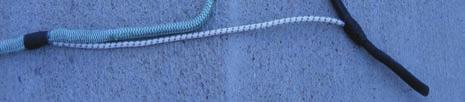


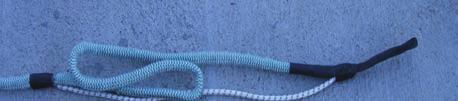


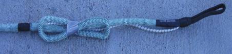


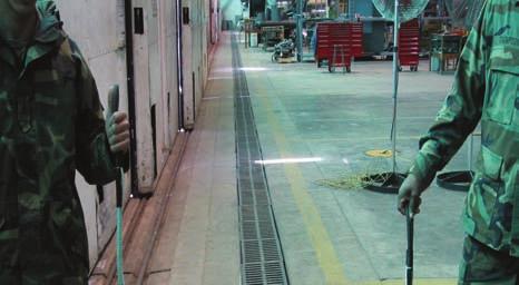
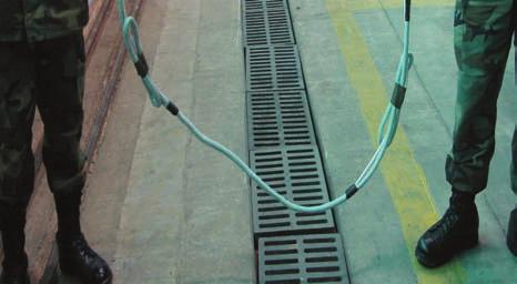
339 TM &P 2 Remove slack from green/white sling by folding it back on itself in line with the bungie (Figure 1,View B) and tape (View C). 3 Repeat steps on opposite end of green/white sling (Figure 1, View D). 4 Configure remaining green/white slings per steps (1), (2), and (3). View A View B View C Figure 1. Preconfigure Green/White Slings View D
340 TM &P Table 3. Disabled UH-60 and Recovery Helicopter Rigging Key to Figure 4 Figure 4 Item No. Item Description 1 Green/White 150 Inches (12.5 Ft) Light Weight Sling 2 Green/White 150 Inches (12.5 Ft) Light Weight Sling 3 Green/White 150 Inches (12.5 Ft) Light Weight Sling 4 Green/White 150 Inches (12.5 Ft) Light Weight Sling 5 Shackle Assembly 6 Black/White 30 Ft Heavy Weight Sling 7 Black/White 30 Ft Heavy Weight Sling with Bridle 8 Sling Link Assembly 9 Yellow/White 153 Inches (12.75 Ft) Light Weight Sling 10 Sling Link Assembly 11 Box Link Assembly 12 Black/White 120 Inches (10 Ft) Light Weight Sling 13 Box Link Assembly 14 Blue/White 360 Inches (30.0 Ft) Light Weight Sling 15 Box Link Assembly 16 Red/White 208 Inches (17.33 Ft) Light Weight Sling 17 Black/White 30 Ft Heavy Weight Sling 18 Sling Link Assembly 19 Cargo Hook Thimble 20 Sling Retention Assembly (SRA) (2) Install preconfigured green/white slings (1), (2), (3) and (4) as follows (Figure 2): (a) Disconnect 4 each de-ice cannon plugs from main rotor distributor and fold back and secure to de-ice cable as shown in (Figure 2, View A). (b) Position mid-point of preconfigured green/white sling on hub arm between the 2 inch inspection holes located on the bottom of hub arms, (Figure 2, View B). (c) Bring slings together on top of hub arm at black whipping and secure with tape/cotton webbing, (Figure 2, View C). View A View B View C Figure 2. Install Green/White Slings NOTE Use sufficient amount of tape/cotton webbing to secure sling around hub to ensure breakaway during lift.. (d) Install Sling Retention Assembly (SRA) as follows (Figure 3): 1 Install round end of SRA into inboard inspection hole of hub arm with handle fully extended OUT and in the LOCKED position

.")
.")

341 TM &P a b c Rotate handle 90 degrees in either direction until the tangs and slots align. Once aligned, insert, PUSH IN, handle until flush. Once handle is flush with SRA, rotate handle 90 degrees in either direction until handle is once again parallel to the long axis of the SRA, (Figure 3, View A). 2 Install triangular end of SRA into outboard inspection hole of hub arm with handle fully extended OUT and in the LOCKED position. As depicted on SRA, (Figure 3, View B). a Rotate handle 90 degrees either direction until the tangs and slots align. b Once aligned, insert, PUSH IN, handle until flush. c Once handles is flush with SRA, rotate handle 90 degrees in either direction until handle is once again parallel to the long axis of the SRA, (Figure 3, View C). View A View B View C Figure 3. Installation of Sling Retention Assemblies Change 3
342 TM &P Figure 4. Disabled UH-60 and Recovery Helicopter Rigging Change 3

.")
343 TM &P (3) Rig Shackle Assembly (Figures 5 and 6). NOTE During shackle assembly rigging and subsequent recovery flight all light weight slings and tie-downs attached to the main rotor blades are to be attached to the clevis part of the shackle assembly, while the heavy weight black-white sling is on the shackle assemblies sling spacer. Figure 5. Rig Shackle Assembly NOTE Shackle assembly must be oriented to where the clevis pin holes are at the 3 and 9 o clock position in relation to the aircraft nose (12 o clock). (a) Remove quick-release pin, clevis pin and sling spacer from the clevis of shackle assembly (Figure 6). (b) Install the leading edge sling eye from 2 o clock blade green/white sling to the 3 o clock pin hole side of clevis (Figure 6, A). (c) Install the trailing edge sling eye from the 4 o clock blade green/white sling to the 3 o clock pin hole side of clevis (Figure 6, B) Change 3
344 TM &P Figure 6. Rigging Shackle Assembly (d) Install the leading edge sling eye from the 4 o clock blade green/white sling to the 3 o clock pin hole side of clevis (Figure 6, C). (e) Install the trailing edge sling eye from the 2 o clock blade green/white slings to the 3 o clock pin hole side of clevis (Figure 6, D). (f) Install the trailing edge sling eye from the 10 o clock blade green/white sling to the 9 o clock pin hole side of clevis (Figure 6, E). (g) Install the leading edge sling eye from the 8 o clock blade green/white sling to the 9 o clock pin hole side of clevis (Figure 6, F). (h) Install the trailing edge sling eye from the 8 o clock blade green/white sling to the 9 o clock pin hole side of clevis (Figure 6, G). (i) Install the leading edge sling eye from the 10 o clock blade green/white sling to the 9 o clock pin hole side of clevis (Figure 6, H). NOTE To avoid sling entanglement with main rotor components the following must be completed. (j) Have assistant raise clevis to remove slack from green/white slings (Figure 7). 1 Gather green/white slings as close as possible to bifilar cover and wrap with tape/cotton webbing (Figure 7, View A) Change 3
.")


345 TM &P 2 Wrap bundle again near top of sling bundle below clevis (Figure 7, View B). 3 Insert quick release pin and spacer and lay shackle assembly aside until required for completion of blade sleeve assembly s and installation of heavy weight black/white sling. View A View B Figure 7. Taping of Rigged Shackle Assembly Change 3
346 (4) Rig and install blade sleeve assemblies as follows (Figure 8): TM &P NOTE Blade sleeve assemblies are attached to each main rotor blade. An adjustable length tie-down is attached between the sleeve assembly s top D-ring and attached to the shackle assembly during the recovery hook-up procedure. A fixed length tie-down is attached to the bottom D-ring of each blade sleeve assembly and secured to an appropriate airframe hard point to secure the main rotor blades during the recovery flight. (a) Orient blade sleeve assembly by holding blue lifting tab so that the TOP and BOTTOM D-rings straps hang freely. (b) Place blade sleeve assembly on ground so that the markings saying TOP on both the blade sleeve and straps are facing down. (c) Assemble blade sleeve pole and place points down near blade sleeve assembly. (d) Open blade sleeve assembly pocket number two on the blade sleeve bag by separating the loop/hook closures. Place tape over either side of Velcro to prevent pocket from closing. (e) Take hold of blade sleeve assembly s left side blade sleeve tab and left side blue lifting tab and place on position 2 of blade sleeve pole. (f) Take hold of blade sleeve assembly s right side blade sleeve tab and right side blue lifting tab and place on position 1 of blade sleeve pole. (g) Place the remaining blue colored lifting tab on the lower edge of the blade sleeve assembly strap onto position 3 of the blade sleeve pole. (h) Verify that appropriate blade sleeve assembly pocket is still open, and all other bag pockets are still closed. (i) Pass the snap hook from one end of the adjustable length tie-down sling through the D-ring on the blade sleeve assembly straps marked TOP and secure snap hook to loop position 2 on the adjustable length tie-down (Figure, 8 View C). (j) Place a portion of the fixed length tie-down in pocket to aid in keeping pocket open while installing blade sleeve assembly. (k) The blade sleeve assembly is now ready for installation onto the rotor blade. NOTE Wrap tape around blade sleeve assembly opening and rotor blade to secure blade sleeve assembly to rotor blade and to prevent rotor wash from blowing blade sleeve assembly off rotor blade. (l) Lift up and rotate blade pole with blade sleeve assembly installed until TOP marking face up. Slide the open blade sleeve assembly onto the rotor blade, while a second person leads the adjustable length tie-down and fixed length tie-down along the rotor blade. CAUTION To prevent possible damage to the main rotor system blade sleeve assembly fixed length tie-downs must be secured snug to aircraft blade tie-down points. (m) Ensure all slack is removed. Secure fixed-length tie-down to appropriate area of airframe

347 TM &P Figure 8. Blade Sleeve Assembly Rigging and Installation
348 TM &P (n) Using the unattached end of the adjustable length tie-down already installed repeat steps (a) through (m) for the opposite facing rotor. (o) Carefully orient the middle of the adjustable length tie-down sling near the main rotor mast for easy access during the shackle assembly hook-up in step (5) of this Paragraph. (p) Repeat steps (a) through (p) above for the other set of rotor blades. NOTE Gain access to installed blade sleeve assembly, by using a ladder, UMARK kit box, etc, to wrap tape around blade sleeve assembly to blade to prevent recovery aircraft rotor wash from blowing the blade sleeve assembly off the blade. (q) Place the mid-point of both adjustable length tie-down slings attached to the top side of the blade sleeves onto the clevis part of the shackle assembly (figure 6). (r) Place double eye end of heavy weight black/white sling (Figure 6), to shackle assembly and secure shackle assembly as follows: 1 Insert sling spacer from shackle assembly into the double eye end opening of heavy weight black/white sling. 2 Align the holes in the shackle assembly clevis with hole in sling spacer. 3 Once holes are aligned, insert the clevis pin through the holes in the shackle assembly clevis and sling spacer. 4 Insert quick-release pin through hole in base of the clevis pin to secure the clevis pin in the clevis. (5) Carefully lay the rigged shackle assembly on the helicopter, and heavy weight black/white sling to the side that the recovery helicopter will approach from for easy access during the recovery helicopter hook-up procedure covered in Paragraph 7 of this WP. c. Install Tail-Boom Rigging (Figure 4 and Table 3). (1) Fold yellow/white sling (Figure 4 #9, View A) in half. (2) Place the two sling eyes of folded yellow/white sling (Figure 4 #9, View A) in-between the heavy weight black/white sling (#7) bridle loops. WARNING Failure to arrange sling eyes on the sling link assembly as shown in Figure 4, View E, will create an unbalanced load on the sling link assembly and may cause the assembly to open as tension is applied to the slings. (3) Connect sling link assembly (Figure 4 #10, View A) through the bridle loops of sling (#7) and through sling eyes of folded yellow/white sling (#9). (a) Verify that arrangement of sling eyes is as shown in Figure 4 View E, with sling (#7) bridle loops in the Position A orientation. (4) Connect box link assembly (Figure 4 #11, View A) to the mid-point fold of sling (#9). (a) Secure sling (#9) to box link using box link pin and quick-release pin (View F). (5) Connect one sling eye of black/white sling (Figure 4 #12, View A), to the other end of box link assembly (#11) installed on folded yellow/white sling (#9)
349 TM &P (a) Secure sling (#12) to box link using box link pin and quick-release pin (View F). (6) Connect box link assembly (Figure 4 #13, View A), to the other sling eye of sling (#12). (a) Secure sling (#12) to box link using box link pin and quick-release pin (View F). (7) Connect one sling eye of blue/white sling (Figure 4 #14, View A), to the other end of box link assembly (#13) installed on black/white sling (#12). (a) Secure sling (#14) to box link using box link pin and quick-release pin (View F). (8) Connect a box link assembly (Figure 4 #15, View A), to the other sling eye of sling (#14). (a) Secure sling (#14) to box link using box link pin and quick-release pin (View F). CAUTION Caution should be taken to ensure that the red/white sling (#16) looped around the tail-boom is hooked in front of the retractable step and secured in place before recovery and throughout the recovery flight to ensure that it does not slide to the rear of the tail-boom. (9) Connect the red/white sling (Figure 4 #16, View A) around the disabled helicopter tail-section as follows: (a) Locate the position on the helicopter tail-section that is approximately aft of the tail landing gear and in front of the retractable step. (b) Center Red/White Sling into 8 foot section of anti-chafe sleeve and secure under tail section. Secure with tape/cotton webbing at top of tail boom (View G). (c) Connect both eyes of sling (#16) to box link (#15) (View A). (d) Secure sling (#16) to box link using box link pin and quick-release pin (View F). (e) Ensure that the retractable step is in the OUT position to maintain sling position. CAUTION To prevent damage to trail rotor blade ensure blade is tied down at root of the blade. (10) To prevent tail rotor blade flapping tie root of lower blade from the tail rotor to the helicopter using a fixed length tie-down (without snap hook). (11) Drogue Chute Installation. NOTE Though not recommended by recovery flight parameters (Table 1), if the ground crew determines it is necessary a drogue chute may be attached to the disabled helicopter to facilitate stable flight. (a) Secure drogue chute to the tail end of tail-boom. Do not deploy drogue chute until recovery helicopter has hovered over disabled or damaged helicopter. (12) The disabled helicopter is now ready for hookup to the recovery helicopter
350 6. RIG RECOVERY HELICOPTER (Figures 4 and 9 and Table 3) TM &P NOTE Figure 4 details the disabled UH-60 helicopter and recovery helicopter rigging. Reference numbers in the following text that are outlined in parentheses [i.e., (1), (2), etc.] refer to Figure 4 and Table 3 item numbers. Refer to figure 4 and Table 3 for configuration guidance. NOTE Tie one end of a long piece of twine, cotton webbing or parachute cord to crossbar of Cargo Hook Thimble. Tie other end of line to the 30' Heavy Weight Black/White Sling. This lanyard will prevent the loss of the Cargo Hook Thimble when the recovered aircraft is released. a. Place a cargo hook thimble (19, Figure 4, View A, and Figure 9) into the single eye end of heavy weight black/white sling with bridle loops (17). b. Connect the single eye end of heavy weight black/white sling (17, Figure 4, View A) with the hook thimble installed, to the recovery helicopter center cargo hook. c. Pull free end of heavy weight black/white sling through center cargo hook hole and secure until helicopter being recovered is ready for hook-up. Figure 9. Typical Cargo Hook Thimble Installation (Shown in Double-eye Configuration) 7. HOOK-UP AND RECOVERY FLIGHT OPERATIONS (Figure 1 and Table 3) WARNING Should it become necessary for a ground crew member to perform hook-up while on the helicopter being recovered, extreme care must be exercised to avoid static electric shock, injury resulting from falling off the helicopter as a result of rotor downwash, etc. CAUTION Remove any loose objects from recovery site to prevent them from becoming projectiles as a result of rotor downwash
351 TM &P NOTE Figure 4 details the disabled UH-60 helicopter and recovery helicopter rigging. Reference numbers in the following text that are outlined in parentheses [i.e., (1), (2), etc.] refer to Figure 4 and Table 3 item numbers. Refer to Figure 4 and Table 3 for configuration guidance. a. Launch recovery helicopter. b. Direct recovery helicopter into hover position slightly to the side of the disabled helicopter where slings (7), Figure 4, View A), have been positioned for connection of the disabled helicopter to the recovery helicopter slings. WARNING Ensure static grounding of recovery helicopter is accomplished by allowing free end of sling lines to touch the ground before ground crew comes in contact with sling. CAUTION Once sling line has come in contact with ground and after sling line comes in contact with ground crew member, the crewmember must maintain continuous contact with the sling line until it is connected to the disabled helicopter to maintain static grounding. c. Allow end of sling line from recovery helicopter to make ground contact to discharge static electricity. WARNING Failure to arrange sling eyes on the sling link assembly as shown in Figure 4, View E, will create an unbalanced load on the sling link assembly and may cause the assembly to open as tension is applied to the slings. d. Connect the single eye end of heavy weight black/white sling (7), Figure 4, View A, (connected to disabled helicopter) to the double eye of heavy weight black/white sling (17) (connected to recovery helicopter) using sling link assembly (18). (1) Verify that the arrangement of sling eyes is as shown in View E, with sling (7) in the Position B orientation. e. Deploy the drogue chute if installed. f. Direct recovery helicopter to place tension on the slings while the ground crew guide the slings to prevent entanglement with the disabled helicopter. g. Evacuate ground crew from rigging site. h. Direct recovery helicopter to take-off with the disabled helicopter connected
352 TM &P POST RECOVERY KIT PROCEDURES Upon reaching the destination with the disabled helicopter, the recovery helicopter must come to a hover with the disabled helicopter a few feet off the ground. It is important that hover time be kept to a minimum to prevent spinning of the disabled helicopter. After the disabled helicopter has been lowered to the ground, the recovery helicopter should be directed to a point where the slings can be released without damaging either helicopter. After an aerial recovery mission has been completed, the UMARK components must be returned to a ready-forissue (RFI) condition. a. Ensure kits usage log is updated to indicate this events use. If this event use is the unit s 20 th usage refer to Work Package for disposition of kit. Kit must be returned to depot maintenance for evaluation. b. All UMARK equipment shall be cleaned, dried, inspected, and replaced, if necessary, in accordance with Work Package Following post recovery component maintenance all UMARK components shall be repacked into the UMARK containers in a neat and orderly fashion. The UMARK containers should then be secured and stored for the next aerial recovery mission
353 TM &P 9. POST RECOVERY DISABLED HELICOPTER PROCEDURES a. Perform main rotor blade Sudden Stoppage inspection in accordance with TM b. Airframe Inspections - Using Aircraft Weight and Balance Record calculate the weight and center of gravity of the aircraft at time of recovery. Plot resulting point on graph on next page. c. If point is below the line above no airframe inspections are required. d. If point is above the line perform the following airframe inspections: (1) Inspect cabin area for cracks, permanent deformation, and loose or missing fasteners in the following areas: (1.1) Frame at Station (1.2) Beams at Buttline 16.5 from Station to Station (1.3) Forward absorber supports from Station to (2) The following empennages are inspected for cracks, permanent deformation, and loose or missing fasteners: (2.1) Lower deck caps, webs, and panel breakers. (2.2) Side skins, lower to upper shear deck. (2.3) Stringers, lower to upper shear deck. (2.4) Forward spar, lower to upper shear deck. (2.5) Fold bulkhead tension joints and associated hardware. e. Transmission Capability Plot the same point on the graph below
354 TM &P f. If the point is below the appropriate line for the model of aircraft recovered no corrective action is required. g. If the point is above the appropriate line for the model of aircraft recovered the gearbox must be removed and returned to depot for inspection. END OF WORK PACKAGE All data and figures in work package has been deleted /( blank)
355
356 TM &P DAMAGED UH-60 MAIN ROTOR, MAIN TRANSMISSION, MAIN TRANSMISSION MOUNT DAMAGE ONE-HOOK LONG-LINE RECOVERY PROCEDURES Index Introduction... 1 Pre-Recovery Procedures... 2 Recovery Flight Parameters and Precautions... 2 Components Required... 3 Damaged Helicopter Rigging... 3 Install Tail-Boom Rigging... 3 Install Forward Main Rigging... 6 Rig Recovery Helicopter Hook-Up and Recovery Flight Operations Post Recovery Kit Procedures Post Recovery Damaged Helicopter Procedures Figures Figure 1. Damaged UH-60 and Recovery Helicopter Rigging... 5 Figure 2. Blade Sleeve Assembly Rigging and Installation... 7 Figure 3. Rigging Shackle Assembly... 9 Figure 4. Typical Cargo Hook Thimble Installation (Shown in Double-Eye Configuration) Tables Table 1. Recovery Helicopter Flight Parameters... 2 Table 2. UMARK Components Required... 3 Table 3. Damaged UH-60 and Recovery Helicopter Rigging - Key to Figure INTRODUCTION This Work Package (WP) covers the rigging of a non-flyable UH-60 with a damaged main rotor, main transmission, and/or main transmission mount using a one-hook long-line recovery procedure, the rigging of a CH-47 recovery helicopter, the recovery flight, and post recovery procedures. The long-line one-hook procedure provides for 90 feet of clearance between the recovery helicopter s single cargo hook in use and the shackle assembly that the damaged helicopter is rigged to. Damaged Main Rotor and/or Transmission non-flyable damaged classification consist of the following: a. Main rotor head mutilated. b. Main rotor shaft/mast bent. c. Main transmission cracked, broken, loose or ripped out of the airframe mounts. d. Engine severely damaged or ripped out (not through a structural lifting point) The ground rigging crew with the Unit Maintenance Aerial Recovery Kit (UMARK) can be deployed separately or with the recovery helicopter. The recovery process includes rigging the damaged helicopter, rigging the recovery helicopter, hooking up the recovery helicopter to the damaged helicopter, and having the recovery helicopter transport the damaged helicopter to a designated site. Refer to Work Package for general information concerning the UMARK function and component details
357 TM &P 2. PRE-RECOVERY PROCEDURES WARNING To prevent catastrophic failure do not use the UMARK if its record log indicates 20 or more aerial recovery uses. Ensure that a pre-usage inspection is performed on the UMARK contents as outlined in Work Package Do not use the UMARK kit if the kits usage log indicates 20 or more uses of the kit. Refer to Work Package for disposition instructions if the kit has 20 or more uses. Do not use the kit if any required content items fail pre-usage inspection. 3. RECOVERY FLIGHT PARAMETERS AND PRECAUTIONS Flight parameters for the applicable recovery helicopter are specified in Table 1. Table 1. Recovery Helicopter Flight Parameters Maximum Airspeed: Maximum Bank Angle: Maximum Rate-of-Climb Maximum Rate-of-Descent Drogue Chute 40 Knots Indicated Air Speed (KIAS) 20 Degrees 500 Feet Per Minute (FPM) 1000 Feet Per Minute (FPM) No WARNING Once the damaged helicopter is connected to the recovery helicopter and lifted to a hover, the pitch attitude of the damaged helicopter must be checked to ensure a nose down attitude is achieved. A damaged helicopter may rotate while in a hover. This rotation may cause slings of some UMARK rigging configurations to twist or to tighten at the main rotor assembly. The rotation will generally stop as airspeed is increased to approximately 5 to 10 knots. The recovery helicopter flight crew should minimize hover time. If oscillations of damaged helicopter develop during flight, tests have shown that lowering airspeed, returning to wings level flight, and initiating a climb has a stabilizing effect. It is critical for the recovery helicopter flight crew to report any unusual occurrences. For example, vertical bounce, severe jerking of the damaged helicopter, hard landing of the damaged helicopter following recovery, UMARK component failure, or exceeding the flight parameters. Report any unusual occurrences to the unit responsible for the damaged helicopter
358 TM &P COMPONENTS REQUIRED WARNING Exceeding the flight parameters may severely damage the main rotor assembly of the damaged helicopter, requiring component replacement. Report the amount and duration of any flight parameter exceeded to the unit responsible for the damaged helicopter. The height above ground level may be difficult to determine during low-level UMARK operations due to the length of the sling system. Flight crews should exercise extreme caution during recovery operations to ensure the damaged helicopter remains clear of ground obstacles. NOTE Recovery of a UH-60 with a damaged main rotor, main transmission, or main transmission mount requires the use of three standard heavy weight black/white slings and one heavy weight black/white sling with bridle loops. The UMARK kit contains on two standard heavy weight black/white slings; the other sling must be obtained from another kit. Components of UMARK utilized during the one-hook, long-line recovery are listed in Table 2. Common equipment used by the ground rigging crew, such as shockproof gloves, goggles, radios, etc., are not included in UMARK. No additional tools are required for UMARK assembly or rigging of the helicopters. Table 2. UMARK Components Required Item Description Qty Item Description Qty Black/White 30 Ft Heavy Weight Sling 3 Fixed Length Tie-Down (With Snap) 4 Black/White 30 Ft Heavy Weight Sling with Bridle 1 Fixed Length Tie-Down (Without Snap) 1 Green/White 150 Inches (12.5 Ft) Light Weight Sling 2 Blade Sleeve Assemblies 4 Blue/White 360 Inches (30.0 Ft) Light Weight Sling 2 Blade Pole Assembly 1 Sling Link Assembly 2 Cargo Hook Thimble 1 Box Link Assembly 2 Drogue Chute 1 Shackle Assembly 1 5. DAMAGED HELICOPTER RIGGING 6. Install Tail-Boom Rigging (Figure 1 and Table 3) NOTE Figure 1 details the damaged and recovery helicopter rigging. Reference numbers in the following text that are outlined in parentheses [i.e., (1), (2), etc.] refer to Figure 1, View A and Table 3 item numbers. Refer to Figure 1, View A and Table 3 for configuration guidance
359 TM &P CAUTION Caution should be taken to ensure that the blue/white sling (1) looped around the tail-boom is hooked in front of the retractable step and secured in place before recovery and throughout the recovery flight to ensure that it does not slide to the rear of the tail-boom. a. Connect the blue/white sling (1), Figure 1, View A, around the damaged helicopter tail section as follows: (1) Locate the position on helicopter tail-section that is approximately aft of the tail landing gear and in front of the retractable step. (2) Loop the blue/white sling (1) under the tail-section. (View B) (3) Connect one eye of blue/white (1) sling to box link (2) and the other eye to box link (3). (View A) (4) Secure sling (1) to each box link using box link pin and quick-disconnect pin. (View C) (5) Ensure that the retractable step is in the OUT position to maintain sling position. b. Install one sling eye of green/white sling (4) to free end of box link assembly (2). (1) Secure sling (4) to box link using box link pin and quick-disconnect pin. (View C) c. Install one eye of green/white sling (5) to the free end of box link assembly (3). (1) Secure sling (5) to box link using box link pin and quick-disconnect pin. (View C) d. Place free ends of green/white slings (4) and (5) on rotor head for easy access during the shack assembly hook-up in Paragraph 7 of this WP. CAUTION To prevent damage to tail rotor blade ensure blade is tied down at root of the blade. e. To prevent tail rotor blade flapping tie root of lower blade from the tail rotor to the helicopter using a fixed length tie-down (without snap hook). f. Drogue Chute Installation NOTE Though not recommended by recovery flight parameters (Table 1), if the ground crew determines it is necessary a drogue chute may be attached to the damaged helicopter to facilitate stable flight. (1) Secure drogue chute to the tail end of tail-boom. Do not deploy drogue chute until recovery helicopter has hovered over disabled or damaged helicopter


360 TM &P Figure 1. Damaged UH-60 and Recovery Helicopter Rigging
361 TM &P Table 3. Damaged UH-60 and Recovery Helicopter Rigging Key to Figure 1 Figure 1 Item Description Item No. 1 Blue/White 360 inches (30.0 Ft) Light Weight Sling 2 Box Link Assembly 3 Box Link Assembly 4 Green/White 150 Inch (12.5 Ft) Light Weight Sling 5 Green/White 150 Inch (12.5 Ft) Light Weight Sling 6 Black/White 30 Ft Heavy Weight Sling 7 Blue/White 360 inches (30.0 Ft) Light Weight Sling 8 Shackle Assembly 9 Black/White 30 Ft Heavy Weight Sling 10 Black/White 30 Ft Heavy Weight Sling with Bridle 11 Sling Link Assembly 12 Black/White 30 Ft Heavy Weight Sling 13 Sling Link Assembly 14 Cargo Hook Thimble 7. Install Forward Main Rigging (Figures 1, 2 and 3, and Table 3) a. Open and remove left and right crewman observation windows that are forward of main cargo doors. b. Fully open the left and right main cargo doors. c. Basket heavy weight black/white sling (6) through the right side crewman s observation window and out the right main cargo door opening. d. Basket light weight blue/white sling (7) through the left side crewman s observation window and out the left main cargo door opening. e. Separately lay both eyes of slings (6) and (7) on the rotor head for easy access during shackle assembly hook-up in step g. of this Paragraph. f. Rig and install blade sleeve assemblies as follows: (Figure 2) NOTE Blade sleeve assemblies are attached to each main rotor blade. A fixed length tie-down is attached to the bottom D- ring of each blade sleeve assembly and secured to an appropriate airframe hard point to secure the main rotor blades during the recovery flight. (1) Orient the blade sleeve assembly (View A) so that the markings saying TOP on both the blade sleeve bag and straps are facing down. (2) Assemble the blade sleeve pole. (View B) (3) Open bag pocket number two on blade sleeve bag (View A) by separating the loop/hook closures. (4) With one hand, take hold of blade sleeve bags left side blade sleeve tab and left side blue lifting tab
362 TM &P Figure 2. Blade Sleeve Assembly Rigging and Installation
363 TM &P (5) With other hand, take hold of blade sleeve bags right side blade sleeve tab and right side blue lifting tab. (6) Rotate the blade sleeve assembly so that the TOP markings are now facing up. (7) Orient blade sleeve open bag pocket so that it is facing away from the user holding the lifting tabs. (8) Place the blade sleeve assembly lifting tabs from the bag and strap that are held in the left hand onto Position 1 of the blade sleeve pole. (View B) (9) Place the blade sleeve assembly lifting tabs being held in the right hand onto Position 2 of the blade sleeve pole. (10) Place the remaining blue colored lifting tab on the lower edge of the blade sleeve assembly strap onto Position 3 of the blade sleeve pole. (11) Verify that the appropriate blade sleeve assembly bag pocket is still open, and all the other bag pockets are still closed. (12) Connect the snap hook from the fixed length tie-down sling to the D-ring on the blade sleeve assembly straps marked BOTTOM. (13) The blade sleeve assembly is now ready for installation onto the rotor blade. (14) Lift up the blade sleeve assembly with the blade sleeve pole and slide the open blade sleeve assembly bag pocket over the forward pointing rotor blade, while a second person leads the fixed length tie-down along the rotor blade. CAUTION To prevent possible damage to the main rotor system assembly fixed length tie-downs must be secured with approximately 18 inches of slack in the lines. (15) Leaving approximately 18 inches of slack, secure the fixed-length tie-down to the appropriate area of the airframe. (16) Repeat steps (1) through (15) for the opposite facing rotor. (17) Repeat steps (1) through (16) for other set of rotor blades. g. Rig Shackle Assembly (Figures 1 and 3, and Table 3) NOTE During shackle assembly rigging and subsequent recovery flight all light weight slings and tie-downs attached to the main rotor blades are to be attached to the clevis part of the shackle assembly, while the heavy weight black/white sling is on the shackle assemblies sling spacer (1) Remove quick-release pin, clevis pin and sling spacer from shackle assembly clevis. (8, Figure 1 and Figure 3)
364 TM &P Figure 3. Rigging Shackle Assembly (2) Install both sling eyes from right side heavy weight black/white sling onto the clevis part of the shackle assembly. (3) Install both sling eyes from left side light weight blue/white sling onto the clevis part of the shackle assembly. (4) Install both free sling eyes from the tail-boom rigging green/white slings onto the clevis part of the shackle assembly. CAUTION Ensure that the sling spacer is installed when the shackle assembly is assembled. (5) Place double eye end heavy weight black/white sling (9), Figure 1, View A, to shackle assembly (Figure 3) and secure shackle assembly as follows: (a) Insert sling spacer from shackle assembly into the double eye end opening of heavy weight black/white sling. (b) Align the holes in the shackle assembly clevis with the hole in the sling spacer. (c) Once holes are aligned, insert the clevis pin through the holes in the shackle assembly clevis assembly and sling spacer. (d) Insert quick-release pin through hole in base of the clevis pin to secure the clevis pin in the clevis
365 TM &P h. Carefully lay the rigged shackle assembly on the helicopter and heavy weight black/white sling (9) to the side that the recovery helicopter will approach from. WARNING Failure to arrange sling eyes on the sling link assembly as shown in Figure 1, View E, will create an unbalanced load on the sling link assembly and may cause the assembly to open as tension is applied to the slings. i. Connect the double eye end of heavy weight black/white sling with bridle loops (10), Figure 1, View A, to the single eye end of heavy weight black/white sling (9) using sling link assembly (11). (6) Verify that arrangement of sling eyes is as shown in View E, with sling (10) in Position A. orientation. j. Extend sling (10) out away from the damaged helicopter for easy access during the recovery helicopter hookup procedure covered in Paragraph 9 of this WP. k. The damaged helicopter is now ready for hookup to the recovery helicopter. 8. RIG RECOVERY HELICOPTER (Figures 1 and 4, and Table 3) NOTE Figure 1 details the damaged and recovery helicopter rigging. Reference numbers in the following text that are outlined in parentheses [i.e., (1), (2), etc.] refer to Figure 1, View A and Table 3 item numbers. Refer to Figure 1, View A and Table 3 for configuration guidance. a. Place a cargo hook thimble (14, Figure 1, View A, and Figure 4) into the single sling eye end of heavy weight black/white sling (12). Figure 4. Typical Cargo Hook Thimble Installation (Shown in Double-Eye Configuration) b. Connect the single eye end of heavy weight black/white sling (12, Figure 1, View A) with the hook thimble installed, to the recovery helicopter center cargo hook. c. Pull free end of heavy weight black/white sling through center cargo hook hole and secure until helicopter being recovered is ready for hook-up
366 TM &P HOOK-UP AND RECOVERY FLIGHT OPERATIONS (Figure 1 and Table 3) WARNING Should it become necessary for a ground crew member to perform hook-up while on the helicopter being recovered, extreme care must be exercised to avoid static electric shock, injury resulting from falling off the helicopter as a result of rotor downwash, etc. a. Launch recovery helicopter. CAUTION Remove any loose objects from recovery site to prevent them from becoming projectiles as a result of rotor downwash. NOTE Figure 1 details the damaged and recovery helicopter rigging. Reference numbers in the following text that are outlined in parentheses [i.e., (1), (2), etc.] refer to Figure 1, View A and Table 3 item numbers. Refer to Figure 1, View A and Table 3 for configuration guidance. b. Direct recovery helicopter into hover position slightly to the side of the damaged helicopter where sling (10), Figure 1, View A, has been positioned for connection of the damaged helicopter to the recovery helicopter sling. WARNING Ensure static grounding of recovery helicopter is accomplished by allowing free end of sling lines to touch the ground before ground crew comes in contact with sling. CAUTION Once sling line has come in contact with ground and after sling line comes in contact with a ground crew member, the crewmember must maintain continuous contact with the sling line until it is connected to the damaged helicopter to maintain static grounding. c. Allow end of sling line from recovery helicopter to make ground contact to discharge static electricity
367 TM &P WARNING Failure to arrange sling eyes on the sling link assembly as shown in Figure 1, View E, will create an unbalanced load on the sling link assembly and may cause the assembly to open as tension is applied to the slings. d. Connect the single eye end of heavy weight black/white sling (10), Figure 1, View A, (connected to the damaged helicopter) to the double eye end of heavy weight black/white sling (12) (connected to the recovery helicopter) using sling link assembly (13) (1) Verify that the arrangement of sling eyes is as shown in View E, with sling (10) in the Position B orientation. e. Deploy the drogue chute if installed. f. Direct recovery helicopter to place tension on the slings while the ground crew guides the slings to prevent entanglement with the damaged helicopter. g. Evacuate ground crew from rigging site. h. Direct recovery helicopter to take-off with the damaged helicopter connected. 10. POST RECOVERY KIT PROCEDURES Upon reaching the destination with the damaged helicopter, the recovery helicopter must come to a hover with the damaged helicopter a few feet off the ground. It is important that hover time be kept to a minimum to prevent spinning of the damaged helicopter. After the damaged helicopter has been lowered to the ground, the recovery helicopter should be directed to a point where the slings can be released without damaging either helicopter. After an aerial recovery mission has been completed, the UMARK components must be returned to a ready-forissue (RFI) condition. a. Ensure kits usage log is updated to indicate this events use. If this event use is the unit s 20 th usage refer to Work Package for disposition of kit. Kit must be returned to depot maintenance for evaluation. b. All UMARK equipment shall be cleaned, dried, inspected, and replaced, if necessary, in accordance with Work Package Following post recovery component maintenance all UMARK components shall be repacked into the UMARK containers in a neat and orderly fashion. The UMARK containers should then be secured and stored for the next aerial recovery mission. 11. POST RECOVERY DAMAGED HELICOPTER PROCEDURES Before returning helicopter to flight status inspect in accordance with applicable technical manuals This is a structurally damaged aircraft. Before returning helicopter to flight status inspect and repair in accordance with appropriate technical manuals and depot repair procedures. END OF WORK PACKAGE
368 TM &P DAMAGED UH-60 TAIL-BOOM DAMAGED ONE-HOOK LONG-LINE RECOVERY PROCEDURES Index Introduction... 1 Pre-Recovery Procedures... 1 Recovery Flight Parameters and Precautions... 2 Components Required... 3 Damaged Helicopter Rigging... 3 Install Main Rotor Rigging... 3 Install Tail-Boom Rigging Rig Recovery Helicopter Hook-Up and Recovery Flight Operations Post Recovery Kit Procedures Post Recovery Damaged Helicopter Procedures Figures Figure 1. Damaged UH-60 and Recovery Helicopter Rigging... 4 Figure 2. Blade Sleeve Assembly Rigging and Installation... 7 Figure 3. Rigging Shackle Assembly... 9 Figure 4. Typical Cargo Hook Thimble Installation (Shown in Double-Eye Configuration) Tables Table 1. Recovery Helicopter Flight Parameters... 2 Table 2. UMARK Components Required... 3 Table 3. Damaged UH-60 and Recovery Helicopter Rigging - Key to Figure INTRODUCTION This Work Package (WP) covers the rigging of a damaged (not damaged) UH-60 using a one-hook long-line recovery procedure, the rigging of a CH-47 recovery helicopter, the recovery flight, and post recovery procedures. The long-line one-hook procedure provides for 90 feet of clearance between the recovery helicopter s single cargo hook in use and the shackle assembly that the damaged helicopter is rigged to. Damaged Tail-Boom classification consists of a tail-boom that is cracked and/or broken and not suitable as a lift point. The ground rigging crew with the Unit Maintenance Aerial Recovery Kit (UMARK) can be deployed separately or with the recovery helicopter. The recovery process includes rigging the damaged helicopter, rigging the recovery helicopter, hooking up the recovery helicopter to the damaged helicopter, and having the recovery helicopter transport the damaged helicopter to a designated site. Refer to Work Package for general information concerning the UMARK function and component details. 2. PRE-RECOVERY PROCEDURES WARNING To prevent catastrophic failure do not use the UMARK if its record log indicates 20 or more aerial recovery uses. Ensure that a pre-usage inspection is performed on the UMARK contents as outlined in Work Package Do not use the UMARK kit if the kits usage log indicates 20 or more uses of the kit. Refer to Work Package for disposition instructions if the kit has 20 or more uses. Do not use the kit if any required content items fail pre-usage inspection
369 TM &P 3. RECOVERY FLIGHT PARAMETERS AND PRECAUTIONS Flight parameters for the CH-47 recovery helicopter are specified in Table 1. Table 1. Recovery Helicopter Flight Parameters Maximum Airspeed: Maximum Bank Angle: Maximum Rate-of-Climb Maximum Rate-of-Descent Drogue Chute 40 Knots Indicated Air Speed (KIAS) 20 Degrees 500 Feet Per Minute (FPM) 1000 Feet Per Minute (FPM) No WARNING Once the damaged helicopter is connected to the recovery helicopter and lifted to a hover, the pitch attitude of the damaged helicopter must be checked to ensure a nose down attitude is achieved. A damaged helicopter may rotate while in a hover. This rotation may cause slings of some UMARK rigging configurations to twist or to tighten at the main rotor assembly. The rotation will generally stop as airspeed is increased to approximately 5 to 10 knots. The recovery helicopter flight crew should minimize hover time. If oscillations of damaged helicopter develop during flight, tests have shown that lowering airspeed, returning to wings level flight, and initiating a climb has a stabilizing effect. It is critical for the recovery helicopter flight crew to report any unusual occurrences. For example, vertical bounce, severe jerking of the damaged helicopter, hard landing of the damaged helicopter following recovery, UMARK component failure, or exceeding the flight parameters. Report any unusual occurrences to the unit responsible for the damaged helicopter. Exceeding the flight parameters may severely damage the main rotor assembly of the damaged helicopter, requiring component replacement. Report the amount and duration of any flight parameter exceeded to the unit responsible for the damaged helicopter. The height above ground level may be difficult to determine during low-level UMARK operations due to the length of the sling system. Flight crews should exercise extreme caution during recovery operations to ensure the damaged helicopter remains clear of ground obstacles
370 TM &P COMPONENTS REQUIRED NOTE Recovery of a UH-60 with a damaged tail-boom requires the use of three standard heavy weight black/white slings and one heavy weight black/white sling with bridle loops; and four sling link assemblies. The UMARK kit contains only two standard heavy weight black/white slings and three sling link assemblies; the other sling and sling link assembly must be obtained from another kit. Components of UMARK utilized during the one-hook, long-line recovery are listed in Table 2. Common equipment used by the ground rigging crew, such as shockproof gloves, goggles, radios, etc., are not included in UMARK. No additional tools are required for UMARK assembly or rigging of the helicopters. Table 2. UMARK Components Required Item Description Qty Item Description Qty Black/White 30 Ft Heavy Weight Sling 3 Shackle Assembly 1 Black/White 30 Ft Heavy Weight Sling with Bridle 1 Fixed Length Tie-Down (With Snap) 4 Green/White 150 Inches (12.5 Ft) Light Weight Sling 4 Fixed Length Tie-Down (Without Snap) 1 Red/White 208 Inches (17.33 Ft) Light Weight Sling 1 Blade Sleeve Assemblies 4 Blue/White 360 Inches (30.0 Ft) Light Weight Sling 1 Blade Pole Assembly 1 Sling Link Assembly 4 Cargo Hook Thimble 1 Box Link Assembly 2 Drogue Chute 1 5. DAMAGED HELICOPTER 6. Install Main Rotor Rigging (Figures 1 and 2, and Table 3) NOTE Figure 1 details the damaged UH-60 helicopter and recovery helicopter rigging. Reference numbers in the following text that are outlined in parentheses [i.e., (1), (2), etc.] refer to Figure 1 and Table 3 item numbers. Refer to Figure 1 and Table 3 for configuration guidance. a. Rotate the main rotor assembly to standard tie-down position. (Figure 1, View B)


371 TM &P Figure 1. Damaged UH-60 and Recovery Helicopter Rigging
372 TM &P Table 3. Damaged UH-60 and Recovery Helicopter Rigging Key to Figure 1 Figure 1 Item Description Item No. 1 Green/White 150 Inches (12.5 Ft) Light Weight Sling 2 Green/White 150 Inches (12.5 Ft) Light Weight Sling 3 Green/White 150 Inches (12.5 Ft) Light Weight Sling 4 Green/White 150 Inches (12.5 Ft) Light Weight Sling 5 Shackle Assembly 6 Black/White 30 Ft Heavy Weight Sling 7 Black/White 30 Ft Heavy Weight Sling with Bridle 8 Sling Link Assembly 9 Black/White 30 Ft Heavy Weight Sling 10 Sling Link Assembly 11 Red/White 208 Inches (17.33 Ft) Light Weight Sling 12 Sling Link Assembly 13 Box Link Assembly 14 Box Link Assembly 15 Blue/White 360 Inches (30.0 Ft) Light Weight Sling 16 Black/White 30 Ft Heavy Weight Sling 17 Sling Link Assembly 18 Cargo Hook Thimble b. Install green/white slings (1), (2), (3) and (4) as follows: (1) Position mid-point of green/white sling (1), View A, under 2 o clock position main rotor blade retention assembly as close to main rotor mast as possible. (View C) (a) Ensure sling does not cross itself at any point. (b) Bring sling eyes together. (2) Position mid-point of green/white sling (2), View A, under 4 o clock position main rotor blade retention assembly as close to main rotor mast as possible. (View C) (a) Ensure sling does not cross itself at any point. (b) Bring sling eyes together. (3) Position mid-point of green/white sling (3), View A, under 8 o clock position main rotor blade retention assembly as close to main rotor mast as possible. (View C) (a) Ensure sling does not cross itself at any point. (b) Bring sling eyes together. (4) Position mid-point of green/white sling (4), View A, under 10 o clock position main rotor blade retention assembly inboard of blade pitch change links and as close to main rotor mast as possible. (View C) (a) Ensure sling does not cross itself at any point. (b) Bring sling eyes together. c. Carefully lay sling eyes for green/white slings (1), (2), (3), and (4) on the helicopter for easy access during the shackle assembly hook-up in step e. of this Paragraph
373 TM &P d. Rig and install blade sleeve assemblies as follows: (Figure 2) NOTE Blade sleeve assemblies are attached to each main rotor blade. A fixed length tie-down is attached to the bottom D- ring of each blade sleeve assembly and secured to an appropriate airframe hard point to secure the main rotor blades during the recovery flight. (1) Orient blade sleeve assembly (Figure 2, View A) so that the markings saying TOP on both the blade sleeve bag and straps are facing down. (2) Assemble blade sleeve pole. (View B) (3) Open bag pocket number two on the blade sleeve bag (View A) by separating the loop/hook closures. (4) With one hand, take hold of blade sleeve bags left side blade sleeve tab and left side blue lifting tab. (5) With other hand, take hold of blade sleeve bags right side blade sleeve tab and right side blue lifting tab. (6) Rotate the blade sleeve assembly so that the TOP markings are now facing up. (7) Orient the blade sleeve open bag pocket so that it is facing away from the user holding the lifting tabs. (8) Place the blade sleeve assembly lifting tabs from the bag and strap that are held in the left hand onto Position 1 of the blade sleeve pole. (View B) (9) Place the blade sleeve assembly lifting tabs being held in the right hand onto Position 2 of the blade sleeve pole. (10) Place the remaining blue colored lifting tab on the lower edge of the blade sleeve assembly strap onto Position 3 of the blade sleeve pole. (11) Verify that appropriate blade sleeve assembly bag pocket is still open, and all other bag pockets are still closed. (12) Connect the snap hook from the fixed length tie-down sling to the D-ring on the blade sleeve assembly straps marked BOTTOM. (13) The blade sleeve assembly is now ready for installation onto the rotor blade
374 TM &P Figure 2. Blade Sleeve Assembly Rigging and Installation
375 TM &P (14) Lift up the blade sleeve assembly with the blade sleeve pole and slide the open blade sleeve assembly bag pocket over the forward pointing rotor blade, while a second person leads the fixed length tie-down along the rotor blade. CAUTION To prevent possible damage to the main rotor system assembly fixed length tie-downs must be secured with approximately 18 inches of slack in the lines. (15) Leaving approximately 18 inches of slack, secure fixed-length tie-down to the appropriate area of airframe. (16) Repeat steps (1) through (15) above for the opposite rotor blade. (17) Repeat steps (1) through (16) above for the other set of rotor blades. e. Rig Shackle Assembly (Figures 1 and 3) NOTE During shackle assembly rigging and subsequent recovery flight all light weight slings and tie-downs attached to the main rotor blades are to be attached to the clevis part of the shackle assembly, while the heavy weight black-white sling is on the shackle assemblies sling spacer. (1) Remove quick-release pin, clevis pin and sling spacer from the clevis of shackle assembly. (5, Figure 1 and Figure 3) (2) Install one sling eye (from leading edge side of blade) from green/white sling attached to the 2 o clock position blade retention assembly onto the clevis part of the shackle assembly. (3) Place both sling eyes (from trailing edge side followed by leading edge side) from green/white sling attached to the 10 o'clock position blade retention assembly onto the clevis part of the shackle assembly. (4) Place the remaining green/white sling eye (from trailing edge side of the blade) from the 2 o clock position blade retention sling onto the clevis part of the shackle assembly. (5) Install one sling eye (from leading edge side of the blade) from green/white sling at the 4 o clock position blade retention assembly onto the clevis part of the shackle assembly. (6) Place both sling eyes (from trailing edge side followed by leading edge side) from green/white sling attached to the 8 o'clock position blade retention assembly onto the clevis part of the shackle assembly. (7) Place the remaining green/white sling eye (from trailing edge side of the blade) from the 4 o clock blade retention sling onto the clevis part of the shackle assembly
376 TM &P CAUTION Ensure that the sling spacer is installed when the shackle assembly is assembled. (8) Place double eye end of heavy weight black/white sling (6), Figure 1, View A, onto shackle assembly (Figure 3) and secure shackle assembly as follows: (a) Insert sling spacer from shackle assembly into the double eye end opening of heavy weight black/white sling. (b) Align the holes in the shackle assembly clevis with hole in sling spacer. (c) Once holes are aligned, insert the clevis pin through the holes in the shackle assembly clevis and sling spacer. (d) Insert quick-release pin through hole in base of the clevis pin to secure the clevis pin in the clevis. f. Carefully lay the rigged shackle assembly on helicopter with the sling spacer facing up, and heavy weight black/white sling to the side that the recovery helicopter will approach from
377 TM &P WARNING Failure to arrange sling eyes on the sling link assembly as shown in Figure 1, View E, will create an unbalanced load on the sling link assembly and may cause the assembly to open as tension is applied to the slings. g. Connect the single eye end of heavy weight black/white sling (6), Figure 1, View A, to the double eye end of heavy weight black/white sling (7) with bridle loops using sling link (8). (1) Verify that the arrangement of sling eyes is as shown in View E, with sling (7), View A, in the Position A orientation. (2) Extend sling (7) out away from the damaged helicopter for easy access during the recovery helicopter hook-up procedure covered in Paragraph 9 of this WP. 7. Install Tail-Boom Rigging (Figure 1 and Table 3) a. Install single sling eye end of heavy weight black/white sling (9), View A, in-between the heavy weight black/white sling (7) bridle loops. WARNING Failure to arrange sling eyes on the sling link assembly as shown in Figure 1, View E, will create an unbalanced load on the sling link assembly and may cause the assembly to open as tension is applied to the slings. b. Connect sling link assembly (10) through the bridle loops of sling (7) and through sling eye of heavy weight black/white sling (9). (1) Verify that arrangement of sling eyes is as shown in View E, with sling (7) bridle loops in the Position A orientation. c. Fold red/white sling (11) in half. d. Place the mid-point fold of folded red/white sling (11) in-between the double sling eyes of heavy weight black/white sling (9). e. Connect sling link assembly (12) through the double loops of sling (9) and through mid-point fold of folded red/white sling (11). (1) Verify that arrangement of sling eyes is as shown in View E, with sling (7) double loops in the Position A orientation. f. Connect one sling eye of folded red/white sling (11) to box link assembly (13). (1) Secure sling (11) eye to box link using box link pin and quick-release pin. (View F) g. Connect other sling eye of folded red/white sling (11) to box link assembly (14). (1) Secure sling (11) eye to box link using box link pin and quick-release pin. (View F) h. Basket blue/white sling (15) under the helicopter at the location where the tail-boom joins the main fuselage, passing the sling down through the eye-ring on the left side of the helicopter, then under the helicopter, and up through the right side eye-ring
 Secure sling (15) to box link using box link pin and quick-release pin. (View F) j.")
378 TM &P i. Connect left side sling eye of blue/white sling (15) to free end of box link assembly (13) installed on folded red/white sling (11). (1) Secure sling (15) to box link using box link pin and quick-release pin. (View F) j. Connect right side sling eye of blue/white sling (15) to free end of box link assembly (14) installed on folded red/white sling (11). (1) Secure sling (15) to box link using box link pin and quick-release pin. (View F) CAUTION To prevent damage to trail rotor blade ensure blade is tied down at root of the blade. k. To prevent tail rotor blade flapping tie root of lower blade from the tail rotor to the helicopter using a fixed length tie-down (without snap hook). l. Drogue Chute Installation NOTE Though not recommended by recovery flight parameters (Table 1), if the ground crew determines it is necessary a drogue chute may be attached to the damaged helicopter to facilitate stable flight. (1) Secure drogue chute to the tail end of tail-boom. Do not deploy drogue chute until recovery helicopter has hovered over disabled or damaged helicopter. m. The damaged helicopter is now ready for hookup to the recovery helicopter. 8. RIG RECOVERY HELICOPTER (Figures 1 and 4 and Table 1) NOTE Figure 1 details the damaged UH-60 helicopter and recovery helicopter rigging. Reference numbers in the following text that are outlined in parentheses [i.e., (1), (2), etc.] refer to Figure 1 and Table 3 item numbers. Refer to Figure 1 and Table 3 for configuration guidance. a. Place a cargo hook thimble (18, Figure 1, View A, and Figure 4) into the single eye end of heavy weight black/white sling (16). Figure 4. Typical Cargo Hook Thimble Installation (Shown in Double-Eye Configuration)
379 TM &P b. Connect the single eye end of heavy weight black/white sling (16, Figure 1, View A) with the hook thimble installed, to the recovery helicopter center cargo hook. c. Pull free end of heavy weight black/white sling through center cargo hook hole and secure until helicopter being recovered is ready for hook-up. 9. HOOK-UP AND RECOVERY FLIGHT OPERATIONS (Figure 1 and Table 3) WARNING Should it become necessary for a ground crew member to perform hook-up while on the helicopter being recovered, extreme care must be exercised to avoid static electric shock, injury resulting from falling off the helicopter as a result of rotor downwash, etc. CAUTION Remove any loose objects from recovery site to prevent them from becoming projectiles as a result of rotor downwash. NOTE Figure 1 details the damaged UH-60 helicopter and recovery helicopter rigging. Reference numbers in the following text that are outlined in parentheses [i.e., (1), (2), etc.] refer to Figure 1 and Table 3 item numbers. Refer to Figure 1 and Table 3 for configuration guidance. a. Launch recovery helicopter. b. Direct recovery helicopter into hover position slightly to the side of the damaged helicopter where sling (7), Figure 1, View A, has been positioned for connection of the damaged helicopter to the recovery helicopter sling. WARNING Ensure static grounding of recovery helicopter is accomplished by allowing free end of sling lines to touch the ground before ground crew comes in contact with sling. CAUTION Once sling line has come in contact with ground and after sling line comes in contact with a ground crew member, the crewmember must maintain continuous contact with the sling line until it is connected to the damaged helicopter to maintain static grounding. c. Allow end of sling line from recovery helicopter to make ground contact to discharge static electricity
380 TM &P WARNING Failure to arrange sling eyes on the sling link assembly as shown in Figure 1, View E, will create an unbalanced load on the sling link assembly and may cause the assembly to open as tension is applied to the slings. d. Connect the single eye end of heavy weight black/white sling (7), Figure 1, View A, (connected to damaged helicopter) to the double eye end of heavy weight black/white sling (16) (connected to recovery helicopter) using sling link assembly (17). (1) Verify that the arrangement of sling eyes is as shown in View E, with sling (7) in the Position B orientation. e. Deploy the drogue chute if installed. f. Direct recovery helicopter to place tension on the slings while the ground crew guide the slings to prevent entanglement with the damaged helicopter. g. Evacuate ground crew from rigging site. h. Direct recovery helicopter to take-off with the damaged helicopter connected. 10. POST RECOVERY KIT PROCEDURES Upon reaching the destination with the damaged helicopter, the recovery helicopter must come to a hover with the damaged helicopter a few feet off the ground. It is important that hover time be kept to a minimum to prevent spinning of the damaged helicopter. After the damaged helicopter has been lowered to the ground, the recovery helicopter should be directed to a point where the slings can be released without damaging either helicopter. After an aerial recovery mission has been completed, the UMARK components must be returned to a ready-forissue (RFI) condition. a. Ensure kits usage log is updated to indicate this events use. If this event use is the unit s 20 th usage refer to Work Package for disposition of kit. Kit must be returned to depot maintenance for evaluation. b. All UMARK equipment shall be cleaned, dried, inspected, and replaced, if necessary, in accordance with Work Package Following post recovery component maintenance all UMARK components shall be repacked into the UMARK containers in a neat and orderly fashion. The UMARK containers should then be secured and stored for the next aerial recovery mission. 11. POST RECOVERY DAMAGED HELICOPTER PROCEDURES Before returning helicopter to flight status inspect in accordance with applicable technical manuals. This is a structurally damaged aircraft. Before returning helicopter to flight status inspect and repair in acordance with appropriate technical manuals and depot repair procedures. END OF WORK PACKAGE /( blank)
381
382 CHAPTER 7 AVIATION UNIT MAINTENANCE INSTRUCTIONS
383 TM &P _ PREVENTATIVE MAINTENANCE CHECKS AND SERVICES (PMCS) _ Index General... 1 Pre-Usage Inspection... 1 Post Recovery Procedures... 3 Tools and Equipment... 5 Cleaning and Storage... 5 General... 5 Nuclear, Biological, Chemical (NBC) Decontamination... 5 Figures Figure 1. Sling Link Assembly Safety Wiring of Spring Lock... 2 Figure 2. UMARK Usage Tracking Form... 4 Tables Table 1. Preventative Maintenance Checks and Services GENERAL Preventive maintenance checks are limited to external inspections and functionality checks of the UMARK components. Service is limited to cleaning and lubrication when applicable. Repairs are limited to replacement of quick-release pins and their associated lanyard assemblies. Assemblies and subassemblies may be replaced as authorized by the Maintenance Allocation Chart (MAC) in Work Package , and requisitioned as specified in the Repair Parts and Special Tools List (RPSTL), Work Packages 0029 and Table 1 identifies the UMARK preventative maintenance checks and services. 2. PRE-USAGE INSPECTION WARNING To prevent catastrophic failure do not use the UMARK kit if its record log indicates 20 or more uses. NOTE Ensure each aircraft recovery (actual flight lifting) is annotated in log. Once a single UMARK kit reaches 20 actual lifts, call Aviation Ground Support Equipment office (SFAE-AV-AS-AG) at (256) or (256) , and turn in UMARK kit for post field analysis. Analysis is also conducted at 40 and 80 lifts for first kit usage only. This analysis is only for first kit reaching 20, 40, and 80 lifts. Normal analysis is visual as described in Table 1. Each UMARK kit contains a usage log that shall be annotated after each usage. Do not use the kit if the usage log indicates 20 or more uses. Upon reaching 20 actual lifts call Aviation Ground Support Equipment office (SFAE-AV- AS-AG) at (256) or (256) , and turn in UMARK kit for post field analysis
384 TM &P _ Table 1 lists preventive maintenance checks, and service and replacement criteria for the UMARK components. A pre-usage inspection is required on those kit items used whose Interval in column (3) is identified as before and after. In addition to Table 1 requirements, the following also applies: a. Prior to use of the UMARK, the kit is to be inspected for completeness. WARNING A lock pin or quick-release pin frozen in the retracted or unlocked position will result in catastrophic failure of the associated component and loss of the recovered helicopter. Check all lock pins and quick-release pins for proper operation. b. All lock pins and quick-release pins are to be inspected for freedom of movement and lubricated as necessary to ensure proper operations. WARNING If safety wire at pivot end of the sling link assembly s spring lock is not present excess loads on the sling link s spring lock may cause the spring lock to open resulting in separation of slings attached to the sling link and possible loss of recovered helicopter. c. At the sling link assembly, the safety wire securing the two sides of the spring lock pivot end must be secured with MS20995C32 safety wire as seen in Figure 1. If the safety wire is missing, broken, or improperly installed replace safety wire as follows: Figure 1. Sling Link Assembly Safety Wiring of Spring Lock (1) Using a 20 inch length of safety wire leave three inches of one end of the safety wire pointing away from and along the center line of the sling link, loop the remaining end of the safety wire two times around the left hand side wire (Point A) of the spring lock and tighten. (2) Take the end of the safety wire just looped under the left hand side wire of the spring lock and loop it twice around the middle two wires of the spring lock and loop twice around the middle two wires of the spring lock (Point B) and tighten
385 TM &P _ (3) Take the end of the safety wire just looped under the middle two wires on the spring lock and loop twice around the right hand side (Point C) of the spring lock and tighten. (4) Bring both ends of the safety wire together, trim to approximately 1.5 inches and twist five times into a pigtail. The excess wire shall be cut off, and the pigtail shall be bent under and into the middle two wires (Point B) of the spring lock in a manner that will prevent it from becoming snagged. CAUTION Improper function of a crossbar assembly spring lock may allow a rope or tie down to slip off when slack. d. The spring locks on the cross bar assembly are to be checked for proper operation. The torsion springs must be seated in the lugs and on the locks. CAUTION Improper spring lock function of a tie-down may allow a rope or tie down to slip off the blade sleeve D-ring when slack. e. The eyehook spring locks on the ropes and adjustable tie downs are to be checked for proper operation. CAUTION If the lifting clevis assembly pivot block is not rotating freely, excess loads on the hub nut of the recovered helicopter may result. f. The pivot block of the lifting clevis must move freely on the clevis pins. 3. POST RECOVERY PROCEDURES Table 1 lists preventive maintenance checks, and service and replacement criteria for the UMARK components. Post recovery procedures consist of performing all items in Table 1 on those items used. NOTE Ensure each aircraft recovery (actual flight lifting) is annotated in its usage log. Once a single UMARK kit reaches 20 actual lifts, call Aviation Ground Support Equipment office (SFAE-AV-AS-AG) at (256) or (256) , and turn in the UMARK kit for post field analysis. Analysis is also conducted at 40 and 80 lifts for first kit usage only. This analysis is only for the first kit reaching 20, 40, and 80 lifts. Normal analysis is visual as described in Table 1. Ensure that kits usage log is annotated with the latest lift usage. Each UMARK kit contains a usage log (Figure 2 UMARK Usage Tracking Form) that shall be annotated after each usage. Upon reaching 20 actual lifts call the Aviation Ground Support Equipment office (SFAE-AV-AS-AG) at (256) or (256) , and turn in the UMARK kit for post field analysis. a. Following post recovery component maintenance all UMARK components shall be repacked into the UMARK containers in a neat and orderly fashion. The UMARK containers should then be secured and stored for the next aerial recovery mission
386 TM &P _ Figure 2. UMARK Usage Tracking Form
387 TM &P _ 4. TOOLS AND EQUIPMENT No special tools or test equipment are required. The following tools are required for the maintenance functions assigned by the Maintenance Allocation Chart (MAC) in Work Package a. Pliers 5. CLEANING AND STORAGE 6. General Metal components of the UMARK can be cleaned with soap and water. Grease, oil, transmission fluids, and hydraulic fluids can be removed from metal components using PD-680, Type II, dry cleaning solvent. The neoprene rubber wedge blocks are cleaned with soap and water. The fabric blade sleeves and drogue chute may only be cleaned with soap and water. The slings, adjustable tie downs, and ropes have braided polyester covers that can only be cleaned with soap and water. The containers are molded polyethylene with stainless steel hardware and can be cleaned with soap and water or PD-680, Type II, dry cleaning solvent. All components should be cleaned and dried before repacking into the containers. Special care shall be given to ensure that all components are thoroughly air dried prior to repackaging. CAUTION Care must be taken to ensure that the pressure relief valves on the containers do not become blocked. 7. Nuclear, Biological, Chemical (NBC) Decontamination The UMARK containers and metal components are watertight and NBC contamination survivable. All kit cable and lanyard assemblies are braided and harbor agents between individual strands, they must therefore be removed and destroyed. The wedge blocks, blade sleeves, drogue chute, slings, adjustable tie downs, and ropes cannot be decontaminated
388 TM &P _ Table 1. Preventative Maintenance Checks and Services (1) Group Number (2) Component to be Inspected (3) Interval (4) Inspection (5) Corrective Action 0001 Slings, Light Weight Before and after each use Inspect polyester cover for wear and white strength members for exposure. There shall be no exposure to white strength members. Replace sling Slings, Heavy Weight Before and after each use Inspect polyester cover for wear and white strength members for exposure. There shall be no exposure to white strength members. Replace sling Adjustable Length Tie- Downs Before and after each use Before and after each use Inspect polyester cover for wear and white strength members for exposure. There shall be no exposure to white strength members. Check eyehook spring locks for positive lock. There shall be no bent pins or missing components. Replace adjustable tie-down. Replace adjustable tie-down Fixed Length Tie-Downs (with snaps) (without snaps) Before and after each use Before and after each use Inspect polyester cover for wear and white strength members for exposure. There shall be no exposure to white strength members. Check eyehook spring locks for positive lock. There shall be no bent pins or missing components. Replace fixed length tie-down. Replace fixed length tie-down. As required Check eyehooks for cleanliness, and serviceability. Clean and lubricate Blade Sleeve Assemblies Before and after each use As required Inspect web stitching for looseness and breaks. There shall be no unraveled stitches or indication of breaks or tears. Inspect blade sleeve assemblies for cleanliness. Repair or replace blade sleeve Assembly. Clean with soap and water
389 TM &P _ Table 1. Preventative Maintenance Checks and Services (Continued) (1) Group Number (2) Component to be Inspected (3) Interval (4) Inspection (5) Corrective Action Before and after each use Inspect canopy and lines for damage. There shall be no torn material or broken lines. Repair or replace drogue chute Drogue Chute As required Inspect stitching for looseness and breaks. There shall be no unraveled stitches or indication of breaks or tears. Repair or replace drogue chute. Before and after each use Check swivel for freedom of movement. Replace drogue chute if swivel cannot be made operable by servicing Wedge Block Assemblies Before and after each use Inspect blocks for fraying, crumbling, and compression. Replace if more than 25% of the material has been lost or the wedge has been permanently compressed by more than 25% of its nominal thickness. Replace wedge block assembly. Check for cleanliness, and serviceability. Wash with soap and water All Wedge Block Assembly Cables. Before and after each use Inspect cable and loops for damage and fraying. Replace cable assembly All Wedge Block Clips Before and after each use Inspect clips for positive closure and deformation. There shall be no deformed clips or clips that will not close. Replace clips Crossbar Assembly Before and after each use Inspect for cracks, bends or deformation in assembly main member and tubes. There shall be no cracks, bends or deformations present. Tube assemblies must be able to be inserted into main member and locked in place preventing use. Replace crossbar assembly. As required Inspect foam fitting for presence of deterioration that will prevent its use. Replace crossbar assembly if foam fitting not present or deteriorated beyond usability. Repair foam fitting or replace crossbar assembly
390 TM &P _ Table 1. Preventative Maintenance Checks and Services (Continued) (1) Group Number (2) Component to be Inspected (3) Interval (4) Inspection (5) Corrective Action Crossbar Quick-Release Pin Before and after each use Inspect quick-release pins for deformation and freedom of movement. Replace quick-release pin if it cannot be made operable by servicing or if deformation is present. Service or replace quick-release pin Crossbar Cable Assemblies Before and after each use Inspect cables and loops for damage. Replace cable if frayed. Reinstall quickrelease pin and secure cable. Replace cable assembly Crossbar Tube Assemblies Refer to group number 0008 for inspections Crossbar Tube Spring Locks Before and after each use Inspect spring lock for positive lock and freedom of movement. Replace crossbar assembly if spring lock has been deformed, has no spring action, or fails to lock. Clean and lubricate as required. Replace crossbar assembly Lifting Clevis Assembly Before and after each use Check that the pivot block can move freely on the clevis pins through its full range of motion. Inspect lifting clevis assembly for damage and cracks. There shall be no damage or cracks, and must move freely. Replace lifting clevis assembly if freedom of motion is not demonstrated. Replace assembly if damaged or cracked. As required Check for cleanliness, and serviceability. Clean with PD-680, Type II, dry cleaning solvent or soap and water. Before and after each use Inspect locking pin hole in pivot block for deformations. Replace lifting clevis assembly Lifting Clevis Assembly Locking Pin Before and after each use Inspect pivot block locking pin. There shall be no deformations. Replace locking pin assembly
391 TM &P _ Table 1. Preventative Maintenance Checks and Services (Continued) (1) Group Number (2) Component to be Inspected (3) Interval (4) Inspection (5) Corrective Action Lifting Clevis Assembly Quick-Release Before and after each use Inspect quick-release pin for deformation and freedom of movement. Replace quickrelease pin if it cannot be made operable by servicing or if deformation is present. Pin As required Check for cleanliness, and serviceability. Clean with PD-680, Type II, dry cleaning solvent or soap and water. Lifting Clevis Assembly Cables Before and after each use As required Inspect cables and loops for damage. Replace cable if frayed. Reinstall quickrelease pin and secure cable. Inspect for cracks, bends or deformation in assembly. There shall be no cracks, bends or deformations present. Replace cable assembly. Repair or replace shackle assembly. Shackle Assembly As required Check for cleanliness, and serviceability. Clean with PD-680, Type II, dry cleaning solvent or soap and water Shackle Shackle Assembly Pin Shackle Assembly Spacer Shackle Assembly Quick-Release Before and after each use Before and after each use Before and after each use Before and after each use Inspect shackle and through holes for deformation and cracks. There shall be no deformation or cracks. Inspect pin for deformation and cracks. There shall be no deformation or cracks. Inspect spacer for freedom of movement and ease in sliding onto the pin. Restricted movement may indicate pin deformation. See Group Replace spacer if deformed. Inspect quick-release pin for deformation and freedom of movement. Replace shackle. Replace shackle pin. Replace shackle assembly spacer. Replace quickrelease pin if it cannot be made operable by servicing or if deformation is present. Pin As required Check for cleanliness, and serviceability. Clean with PD-680, Type II, dry cleaning solvent or soap and water
392 TM &P _ Table 1. Preventative Maintenance Checks and Services (Continued) (1) Group Number (2) Component to be Inspected (3) Interval (4) Inspection (5) Corrective Action Shackle Assembly Cable Assembly Sling Link Assemblies Box Link Assemblies Before and after each use Before and after each use Before and after each use Inspect cables and loops for damage. Replace cable if frayed. Reinstall quickrelease pin and secure cable. Inspect pin for deformations. Check spring locking operation. There shall be no deformation to spring locking clips. Inspect safety wire at pivot end of spring lock. If missing, broken, or improperly installed (Figure 2), replace safety wire in accordance with Paragraph 1, Step c. Replace cable assembly. Replace if deformed. Replace assembly if spring lock cannot be closed. Replace safety wire in accordance with Paragraph 1, Step c. As required Check for cleanliness, and serviceability. Clean with PD-680, Type II, dry cleaning solvent or soap and water. As required Check for cleanliness, and serviceability. Clean with PD-680, Type II, dry cleaning solvent or soap and water Box Link Box Link Pin- Lanyard Assembly Box Link Pin Assembly Box Link Cable Assembly Box Link Quick- Release Pins Before and after each use As Required Before and after each use Before and after each use Before and after each use Inspect for deformations and cracks. Inspect box link pin holes for deformation. There shall be no deformations or cracks. Inspect lanyard and loops for damage. Replace lanyard if frayed. Reinstall quickrelease pin and secure lanyard. Inspect box link pin. There shall be no deformations. Inspect cables and loops for damage. Replace cable if frayed. Reinstall quickrelease pin and secure cable. Inspect quick-release pin for deformation and freedom of movement. Replace box link. Replace lanyard assembly. Replace box link pin assembly. Replace cable assembly. Replace quickrelease pin if it cannot be made operable by servicing or if deformation is present. As required Check for cleanliness, and serviceability. Clean with PD-680, Type II, dry cleaning solvent or soap and water
393 TM &P _ Table 1. Preventative Maintenance Checks and Services (Continued) (1) Group Number (2) Component to be Inspected (3) Interval (4) Inspection (5) Corrective Action 0013 After each use Inspect case and gasket for damage. Check latches and handles for damage. Decontaminate exterior. NBC Containers As required Check for cleanliness, and serviceability. Decontaminate exterior. Replace if container is damaged, cracked, or gasket or latches are damaged. Clean with PD-680, Type II, dry cleaning solvent or soap and water Blade Pole Assembly As Required As Required Check for serviceability. Check for cleanliness. Replace blade pole assembly and/or quick-release pins and/or lanyards if damaged or unserviceable. Clean with PD-680, Type II, dry cleaning solvent or soap and water Cargo Hook Thimbles Before and after each use Inspect thimble for deformation and damage to sling mating surfaces. There shall be no cracks or deformations. Replace if deformed or damaged. As required Check for cleanliness. Clean with PD-680, Type II, dry cleaning solvent or soap and water. END OF WORK PACKAGE /( blank)
394
395 CHAPTER 8 SUPPORTING INFORMATION
396 TM &P _ REFERENCES _ DICTIONARIES OF TERMS AND ABBREVIATIONS AR AR Publications Indexes DA PAM LOGISTICS AND STORAGE Dictionary of United States Army Terms Abbreviations and Brevity Codes Consolidated Index of Army Publications and Blank Forms TM General Aircraft Maintenance Manual TM Storage and Materials Handling MAINTENANCE OF SUPPLIES AND EQUIPMENT AR DA PAM OTHER PUBLICATIONS AR AR AR DA PAM FM TM Army Material Maintenance Policy and Retail Maintenance Operations Functional Users Manual for The Army Maintenance Management System Aviation (TAMMS-A) Fire and Emergency Services Reporting of Transportation Discrepancies in Shipment Reporting of Supply and Packaging Discrepancies Administrative Publications: Action Officers Guide First Aid for Soldiers Procedures for the Destruction of Aviation Ground Support Equipment (FSC 4920) to Prevent Enemy Use END OF WORK PACKAGE /( blank)
397
398 TM &P _ MAINTENANCE ALLOCATION CHART _ INTRODUCTION The Army Maintenance System MAC The Maintenance Allocation Chart (MAC) assigns maintenance functions in accordance with the Aviation Maintenance concept for Army aviation. Overall authority and responsibility is designated for the performance of maintenance functions on the identified component. The application of the maintenance function is consistent with the capacities and capabilities of Aviation Unit Maintenance (AVUM) and Aviation Intermediate Maintenance (AVIM) units. AVUM and AVIM maintenance assignments are shown on the MAC in column (4) as: AVUM corresponds to an O code in the Repair Parts and Special Tools List (RPSTL). AVIM corresponds to an F code in the RPSTL. Use of the Maintenance Allocation Chart NOTE Approved item names are used throughout this MAC. Generic terms/nomenclature (if any) are expressed in parentheses and are not to be considered as official terminology. This Maintenance Allocation Chart assigns maintenance functions to the lowest level of maintenance. Only the lowest level of maintenance authorized to perform a maintenance function is indicated. If the lowest maintenance level cannot perform all tasks of any single maintenance function (e.g., repair), then the higher maintenance level(s) that can accomplish additional tasks will also be indicated. A maintenance function assigned to a maintenance level will be automatically authorized to be performed at any higher maintenance level. A maintenance function that cannot be performed at the assigned level of maintenance for any reason may be evacuated to the next higher maintenance level. Higher maintenance levels will perform the maintenance functions of lower maintenance levels when required by the commander who has the authority to direct such tasking. The assignment of a maintenance function will not be construed as authorization to carry the related repair parts or spares in stock. Information to requisition or otherwise secure the necessary repair parts will be as specified in the associated Repair Parts and Special Tools List (RPSTL). Maintenance Functions Maintenance functions are limited to and defined as follows: a. Inspect. To determine the serviceability of an item by comparing its physical, mechanical, and/or electrical characteristics with established standards through examination (e.g., by sight, sound, or feel). b. Service. Operations required periodically to keep an item in proper operating condition; e.g., to clean (includes decontaminate, when required), to preserve, to drain, to paint, or to replenish fuel, lubricants, chemical fluids, or gases. c. Remove/Install. To remove and install the same item when required to perform service or other maintenance functions. Install may be the act of emplacing, seating, or fixing into position a spare, repair part, or module (component or assembly) in a manner to allow the proper functioning of an equipment or system. d. Replace. To remove an unserviceable item and install a serviceable counterpart in its place. Replace is authorized by the MAC and assigned maintenance level is shown as the 3rd position code of the SMR code
399 TM &P _ e. Repair. The application of maintenance services including fault isolation/troubleshooting, removal/installation, and disassembly/assembly procedures, to identify troubles and restore serviceability to an item by correcting specific damage, fault, malfunction, or failure in a part, subassembly, module (component or assembly), end item, or system. NOTE The following definitions are applicable to the repair maintenance function: Services - Inspect, service, and/or replace Fault location/troubleshooting - the process of investigating and detecting the cause of equipment malfunctioning. Disassembly/assembly - the step-by-step taking apart (or breakdown) of a spare/functional group coded item to the level of its least component that is assigned an SMR code for the level of maintenance under consideration. Explanation of Columns in the MAC Column (1) - Group Number. Column (1) lists functional group code numbers, the purpose of which is to identify maintenance significant components, assemblies, subassemblies, and modules with the next higher assembly. Column (2) - Component/Assembly. Column (2) contains the item names of components, assemblies, subassemblies, and modules for which maintenance is authorized. Column (3) - Maintenance Function. Column (3) lists functions to be performed on item listed in Column (2). (For detailed explanation of these functions, refer to Maintenance Functions outlined above.) Column (4) - Maintenance Level. Column (4) specifies each level of maintenance authorized to perform each function listed in Column (3), by indicating work time required (expressed as hours in whole hours or decimals) in the appropriate sub-column. This work time figure represents the active time required to perform that maintenance function at the indicated level of maintenance. If the number or complexities of the tasks within the listed maintenance function vary at different maintenance levels, appropriate work-time figures are to be shown for each level. The work-time figure represents the average time required to restore an item (assembly, sub assembly, component, module, end item, or system) to a serviceable condition under typical field operating conditions. This time includes preparation time (including any necessary disassembly/assembly time), troubleshooting/fault location time, and quality assurance time in addition to the time required to perform the specific tasks identified for the maintenance functions authorized in the maintenance allocation chart. a. C- Crew or operator maintenance done within organization or aviation unit maintenance b. O - Aviation Unit Maintenance c. F - Aviation Intermediate Maintenance d. H - General support maintenance e. L - Specialized repair activity f. D - Depot Maintenance Column (5) - Tools. Column (5) specifies the tool required to perform the designated function. Column (6) Remarks
400 TM &P _ MAINTENANCE ALLOCATION CHART - UNIT MAINTENANCE AERIAL RECOVERY KIT (1) Group Number (2) Component/ Assembly (3) Maint. Function (4) Maintenance Level C O F H L D (5) Tools (6) Remarks 0001 Slings, Light Weight Inspect 0.1 Pliers Preventative Maintenance Checks and Services (PMCS) Replace Slings, Heavy Weight Inspect 0.1 PMCS Replace Adjustable Length Tie-down 10K MBS Inspect 01. PMCS Service 0.2 PMCS Replace Rope 10K MBS Inspect 0.1 PMCS Service 0.2 PMCS Replace Blade Sleeve Inspect 0.1 PMCS Service 0.5 PMCS Replace Drogue Chute Inspect 0.1 PMCS Service 0.5 PMCS Replace Wedge Block Inspect 0.1 PMCS Service 0.2 PMCS Replace Cable Assembly Inspect 0.1 PMCS Service 0.2 PMCS Replace 0.1 Pliers
401 TM &P _ MAINTENANCE ALLOCATION CHART - UNIT MAINTENANCE AERIAL RECOVERY KIT (1) Group Number (2) Component/ Assembly (3) Maint. Function (4) Maintenance Level C O F H L D (5) Tools (6) Remarks Snap Hook Inspect 0.1 Preventative Maintenance Checks and Services (PMCS) Replace Crossbar Assembly Inspect 0.2 PMCS Service 0.5 PMCS Replace Quick Release Pin Inspect 0.1 PMCS Service 0.2 PMCS Replace Cable Assembly Inspect 0.1 PMCS Replace 0.1 Pliers Tube Assembly Inspect 0.1 PMCS Replace Spring Lock Inspect 0.1 PMCS Replace Lifting Clevis Assembly Inspect 0.1 PMCS Service 0.2 PMCS Replace Locking Pin Inspect 0.1 PMCS Replace Quick Release Pin Inspect 0.1 PMCS Service 0.2 PMCS Replace
402 TM &P _ MAINTENANCE ALLOCATION CHART - UNIT MAINTENANCE AERIAL RECOVERY KIT (1) Group Number (2) Component/ Assembly (3) Maint. Function (4) Maintenance Level C O F H L D (5) Tools (6) Remarks Cable Assembly Inspect 0.1 Preventative Maintenance Checks and Services (PMCS) Replace 0.1 Pliers 0010 Shackle Assembly Inspect 0.1 PMCS Service 0.2 PMCS Replace Shackle Inspect 0.1 PMCS Replace Pin Inspect 0.1 PMCS Replace Spacer Inspect 0.1 PMCS Replace Quick Release Pin Inspect 0.1 PMCS Service 0.2 PMCS Replace Cable Assembly Inspect 0.1 PMCS Replace Sling Link Assembly Inspect 0.1 PMCS Service 0.1 PMCS Replace Box Link Assembly Inspect 0.1 PMCS Service 0.2 PMCS Replace
403 TM &P _ MAINTENANCE ALLOCATION CHART - UNIT MAINTENANCE AERIAL RECOVERY KIT (1) Group Number (2) Component/ Assembly (3) Maint. Function (4) Maintenance Level C O F H L D (5) Tools (6) Remarks Box Link Inspect 0.1 Preventative Maintenance Checks and Services (PMCS) Replace Pin-Lanyard Assembly Inspect 0.1 PMCS Replace Pin-Box Link Inspect 0.1 PMCS Replace Cable Assembly Inspect 0.1 PMCS Replace Quick Release Pin Inspect 0.1 PMCS Service 0.2 PMCS Replace NBC Container Inspect 0.1 PMCS Service 0.2 PMCS Replace Place Pole Assembly Tail Hook Service 0.1 PMCS Inspect 0.1 Service 0.2 PMCS Replace Yoke Inspect 0.1 PMCS Service 0.2 PMCS Replace
404 TM &P _ MAINTENANCE ALLOCATION CHART - UNIT MAINTENANCE AERIAL RECOVERY KIT (1) Group Number (2) Component/ Assembly (3) Maint. Function (4) Maintenance Level C O F H L D (5) Tools (6) Remarks Quick Release Pin Inspect 0.1 Preventative Maintenance Checks and Services (PMCS) Service 0.2 PMCS Replace Cable Assembly Inspect 0.1 PMCS Replace Upper Handle Inspect 0.1 PMCS Service 0.2 PMCS Replace Lower Handle Inspect 0.1 PMCS Service 0.2 PMCS Replace Hook Thimble Inspect 0.1 PMCS Service 0.2 PMCS Replace 0.1 END OF WORK PACKAGE /( blank)
405
406 TM &P _ REPAIR PARTS AND SPECIAL TOOL LIST INTRODUCTION _ Scope This RPSTL lists and authorizes spares and repair parts required for performance of aviation unit and aviation intermediate maintenance of the Unit Maintenance Aerial Recovery Kit. It authorizes the requisitioning, issue, and disposition of spares and repair parts as indicated by the source, maintenance and recoverability (SMR) codes. General In addition to this explanatory section, this Repair Parts and Special Tools List is divided into the following sections: a. Repair Parts List. A list of spares and repair parts authorized by this RPSTL for use in the performance of maintenance. The list also includes parts that must be removed for replacement of the authorized parts. Parts lists are composed of functional groups in ascending alphanumeric sequence, with the parts in each group listed in ascending figure and item number sequence. Bulk materials are listed in item name sequence. b. Special Tools List. No special tools or test equipment are required. c. Cross-reference Indexes. Not applicable. Explanation of Columns in RPSTL Work Packages ITEM NO. - Column (1). Indicates the number used to identify items called out in the illustration. SMR CODE - Column (2). The source, Maintenance, and Recoverability (SMR) code is a 5-position code containing supply/requisitioning information, maintenance category authorization criteria, and disposition instruction, as shown in the following breakout:
407 TM &P _ a. Source Code. The source code tells you how to get an item needed for maintenance, repair, or overhaul of an end item/equipment. Explanations of source codes are shown in Table 1. Table 1. Source Code Definitions Source Code PA, PB, PC**, PD, PE, PF, PG Application/Explanation Stocked items; use an applicable NSN to request/requisition items with these source codes. They are authorized to the category indicated by the code entered in the 3 rd position of the SMR code. ** Items coded PC are subject to deterioration. KD, KF, KB MO - Made at Unit/AVUM Level MF - Made at DS/AVIM Level MH - Made at GS Level ML - Made at SRA MD - Made at Depot AO - Assembled by Unit/AVUM Level AF - Assembled by DS/AVIM Level AH - Assembled by GS Level AL - Assembled by SRA AD - Assembled by Depot XA XB XC Items with these codes are not to be requested/requested/ requisitioned individually. They are part of a kit that is authorized to be the maintenance category indicated in the 3 rd position of the SMR code. The complete kit must be requisitioned and applied. Items with these codes are not to be requested/requisitioned individually. They must be made from bulk material that is identified by the part number in the DESCRIPTION AND USABLE ON CODE (UOC) column and listed in the Bulk Material group of the repair parts list in this RPSTL. If the item is authorized to you by the 3 rd position code of the SMR code, but the source code indicates it is made at a higher level, order the item from the higher level of maintenance. Items with these codes are not to be requested/requisitioned individually. The parts that make up the assembled item must be requisitioned or fabricated and assembled at the level of maintenance indicated by the source code. If the 3 rd position code of the SMR code authorizes you to replace the item, but the source code indicates the item is assembled at a higher level, order the item from the higher level of maintenance. Do not requisition an XA - coded item. Order its next higher assembly. (Also, refer to the NOTE below.) If an XB item is not available from salvage, order it using the CAGEC and part number Installation drawing, diagram, instruction sheet, field service drawing, that is identified by manufacturer s part number. Item is not stocked. Order an XD - coded item through normal supply XD channels using the Commercial and Government-Entity (CAGEC) code and part number given. NOTE: Cannibalization or controlled exchange, when authorized, may be used as a source of supply for items with the above XA, XB, XC, and XD source codes, except for those source coded XA
408 TM &P _ b. Maintenance Code. Maintenance codes tell you the level(s) of maintenance authorized to USE and REPAIR support items. The maintenance codes are entered in the third and fourth positions of the SMR Code. (1) The maintenance code entered in the third position (defined in Table 2) tells you the lowest maintenance level authorized to remove, replace, and use an item. The maintenance code entered in the third position will indicate authorization to a maintenance level. Table 2. Third Position Maintenance Code Definitions Maintenance Code C O F H L D Application/Explanation Crew or operator maintenance done within organizational or aviation unit maintenance. Organizational or aviation unit category can remove, replace, and use the item. Direct support or aviation intermediate level can remove, replace, and use the item. General support level can remove, replace, and use the item. Specialized repair activity can remove, replace, and use the item. Depot level can remove, replace, and use the item. (2) The maintenance code entered in the fourth position (defined in Table 3) tells whether or not the item is to be repaired and identifies the lowest maintenance level with the capability to do complete repair (i.e., perform all authorized repair functions.) NOTE Some limited repair may be done on the item at a lower level of maintenance, if authorized by the Maintenance Allocation Chart (MAC) and SMR codes. This position will contain one of the following maintenance codes. Table 3. Fourth Position Maintenance Code Definitions Maintenance Code O F H L D Z B Application/Explanation Organizational or aviation unit is the lowest level that can do complete repair of the item. Direct support or AVIM is the lowest level that can do complete repair of the item. General support is the lowest level that can do complete repair of the item. Specialized repair activity (designate the specialized repair activity) is the lowest level that can do complete repair of the item. Depot is the lowest level that can do complete repair of the item. Non-repairable. No repair is authorized. No repair is authorized. (No parts or special tools are authorized for the maintenance of a B coded item). However, the item may be reconditioned by adjusting, lubricating, etc., at the user level
409 TM &P _ c. Recoverability Code. Recoverability codes (Table 4) are assigned to items to indicate the disposition action on unserviceable items. The recoverability code is entered in the fifth position of the SMR Code as follows: Table 4. Fifth Position Recoverability Code Definitions Recoverability Code Z O F H D L A Application/Explanation Non-repairable item. When unserviceable, condemn and dispose of the item at the level of maintenance shown in 3 rd position of SMR Code. Reparable item. When uneconomically reparable, condemn and dispose of the item at organizational or aviation unit level. Reparable item. When uneconomically reparable, condemn and dispose of the item at the direct support or aviation intermediate level. Reparable item. When uneconomically reparable, condemn and dispose of the item at the general support level. Reparable item. When beyond lower level repair capability, return to depot. Condemnation and disposal of item not authorized below depot level. Reparable item. Condemnation and disposal not authorized below specialized repair activity (SRA). Item requires special handling or condemnation procedures because of specific reasons (e.g., precious metal content, high dollar value, critical material, or hazardous material). Refer to appropriate manuals/directives for specific instruction. CAGE - Column (3). The Commercial and Government-Entity Code is a 5-digit code which is used to identify the manufacturer, distributor, or Government agency/activity that supplies the item. PART NUMBER - Column (4). Indicates the primary number used by the manufacturer (individual, company, firm, corporation, or Government activity), which controls the design and characteristics of the item by means of its engineering drawings, specifications standards, and inspection requirements to identify an item or range of items. NOTE When you use a NSN to requisition an item, the item you receive may have a different part number from the part ordered. DESCRIPTION AND USABLE ON CODE (UOC) - Column (5). This column includes the following information: a. The Federal item name and, when required, a minimum description to identify the item. b. Spare/repair parts that make up an assembled item are listed immediately following the assembled item line entry. c. Part numbers for bulk materials are referenced in this column in the line item entry for the item to be manufactured/fabricated. d. The usable on code, when applicable. e. The statement END OF FIGURE appears just below the last item description in Column (5) for a given fixture
410 TM &P _ QTY - Column (6). The QTY (quantity per figure column) indicates the quantity of the item used in the breakout shown on the illustration/figure, which is prepared for a functional group, sub-functional group, or an assembly. AV appearing in this column in lieu of a quantity indicates that the quantity is variable and the quantity may vary from application to application. Special Information. a. USABLE ON CODE. The usable on code appears in the lower left corner of the Description column heading. Usable on codes are shown as UOC in the Description Column (justified left) on the first line applicable item description/nomenclature. Un-coded items are applicable to all models. b. FABRICATION INSTRUCTIONS. Part numbers for bulk materials are referenced in the description column of the line item entry for the item to be manufactured/fabricated. c. How To Locate Repair Parts. (1) First. Determine the assembly group or subassembly group to which the item belongs. This is necessary since figures are prepared for assembly groups and subassembly groups, and listings are divided into the same groups. (2) Second. Find the figure covering the assembly group or subassembly group to which the item belongs (3) Third. Identify the item on the figure and use the Figure and Item Number Index to find the part number. Abbreviations. Not applicable. END OF WORK PACKAGE /( blank)
411
412 TM &P _ REPAIR PARTS AND SPECIAL TOOL LIST ITEM LISTING _ Figure 1. Light Weight Slings (94D519-1, -2, -3, -4, 5)
413 TM &P _ Figure 1. Group 0001 Light Weight Slings (94D519-1, -2, -3, -4, 5) (1) ITEM NO (2) SMR CODE (3) CAGE (4) PART NUMBER (5) DESCRIPTION AND USABLE ONE CODES (UOC) 1 XDODA D519-1 Sling, Light Weight, Green/White, Feet 2 XDODA D519-2 Sling, Light Weight, Yellow/White, Feet 3 XDODA D519-3 Sling, Light Weight, Red/White, Feet 4 XDODA D519-4 Sling, Light Weight, Blue/White, Feet 5 XDODA D519-5 Sling, Light Weight, Black/White Feet (6) QTY END OF FIGURE
414 TM &P _ Figure 2. Heavy Weight Slings (94H520-1, 2)
415 TM &P _ Figure 2. Group 0002 Heavy Weight Slings (94H520-1, 2) (1) ITEM NO (2) SMR CODE (3) CAGE (4) PART NUMBER (5) DESCRIPTION AND USABLE ONE CODES (UOC) (6) QTY 1 2 XDODA H520-1 XDODA H520-2 Sling, Heavy Weight, Black/White, Feet Sling, Heavy Weight, Black/White... with Bridle,30 Feet 2 1 END OF FIGURE
416 TM &P _ Figure 3. Adjustable Length Tie-Downs (94D521-1, -2)
417 TM &P _ (1) ITEM NO (2) SMR CODE Figure 3. Group 0003 Adjustable Length Tie-Downs (94D521-1, -2) (3) CAGE (4) PART NUMBER (5) DESCRIPTION AND USABLE ONE CODES (UOC) 1 XDODA D521-1 Adjustable Length Tie Down XDODA D521-2 Sling Extension... 4 END OF FIGURE (6) QTY
418 TM &P _ Figure 4. Ropes (94C522-1, -2)
419 TM &P _ (1) ITEM NO (2) SMR CODE (3) CAGE Figure 4. Group 0004 Ropes (94C522-1, -2) (4) PART NUMBER (5) DESCRIPTION AND USABLE ONE CODES (UOC) 1 XDODA C522-1 Fixed-Length Tie-Down XDODA C522-2 Snapless Tie-Down... 1 END OF FIGURE (6) QTY
420 TM &P _ Figure 5. Blade Sleeves (94J516-1)
421 TM &P _ (1) ITEM NO (2) SMR CODE (3) CAGE Figure 5. Group 0005 Blade Sleeves (94J516-1) (4) PART NUMBER (5) DESCRIPTION AND USABLE ONE CODES (UOC) 1 XDOZA J516-1 Blade Sleeve... 4 END OF FIGURE (6) QTY
422 TM &P _ Figure 6. Drogue Chute (1670EG029B3)
423 TM &P _ (1) ITEM NO (2) SMR CODE (3) CAGE Figure 6. Group 0006 Drogue Chute (1670EG029B3) (4) PART NUMBER (5) DESCRIPTION AND USABLE ONE CODES (UOC) 1 XDOZA EG029B3 Chute, Drogue... 1 END OF FIGURE (6) QTY
424 TM &P _ Figure 7. Wedge Blocks (94D527-1, 94D528-1, 94D529-1, 94D530-1)
425 TM &P _ (1) ITEM NO (2) SMR CODE Figure 7. Group 0007 Wedge Blocks (94D527-1, 94D528-1, 94D529-1, 94D530-1) (3) CAGE (4) PART NUMBER (5) DESCRIPTION AND USABLE ONE CODES (UOC) 1 XDOZA D527-1 OH-58 Sight Wedge XDOZA D528-1 UH-1 Square Wedge XDOZA D529-1 AH-1 Mast Wedge XDOZA D530-1 OH-58 A/C Mast Wedge... 1 END OF FIGURE (6) QTY
426 TM &P _ Figure 8. Crossbar Assembly (94H501-1)
427 TM &P _ (1) ITEM NO (2) SMR CODE (3) CAGE Figure 8. Group 0008 Crossbar Assembly (94H501-1) (4) PART NUMBER (5) DESCRIPTION AND USABLE ONE CODES (UOC) XDOOA H501-1 Cross Bar Assembly XDOZA J502-1 Crossbar XDOZA H504-1 Foam Fitting XDOZA D505-1 Tube Assembly PAOZZ MS17985C1237 Quick Release Pin PAOZZ MS Swaging Sleeve PAOZZ MIL-W-83420/4-002 Wire Rope, 21 Inches... 4 END OF FIGURE (6) QTY
428 TM &P _ Figure 9. Lifting Clevis Assembly (94D509-1)
429 TM &P _ (1) ITEM NO (2) SMR CODE (3) CAGE Figure 9. Group 0009 Lifting Clevis Assembly (94D509-1) (4) PART NUMBER (5) DESCRIPTION AND USABLE ONE CODES (UOC) XDOOA D509-1 Lifting Clevis Assembly XDOZA C Locking Pin PAOZZ MS17987C406 Quick Release Pin PAOZZ MS Swaging Sleeve PAOZZ MIL-W-83420/4- Wire Rope PAOZZ MS Swaging Sleeve... 1 END OF FIGURE (6) QTY
430 TM &P _ Figure 10. Shackle Assembly (94D514-1)
431 TM &P _ (1) ITEM NO (2) SMR CODE (3) CAGE Figure 10. Group 0010 Shackle Assembly (94D514-1) (4) PART NUMBER (5) DESCRIPTION AND USABLE ONE CODES (UOC) XDOOA D514-1 Shackle Assembly XDOZA Shackle XDOZA D514-2 Pin XDOZA C515-1 Spacer PAOZZ MS17987C617 Quick Release PAOZZ MIL-W-83420/4- Wire Rope, 23.6 Inches PAOZZ MS Swaging Sleeve... 2 END OF FIGURE (6) QTY
432 TM &P _ Figure 11. Sling Link Assembly (94H523-1)
433 TM &P _ (1) ITEM NO (2) SMR CODE (3) CAGE Figure 11. Group 0011 Sling Link Assembly (94H523-1) (4) PART NUMBER (5) DESCRIPTION AND USABLE ONE CODES (UOC) 1 XDOZA H523-1 Sling Link Assembly... 3 END OF FIGURE (6) QTY
434 TM &P _ Figure 12. Box Link Assembly (94C524-1)
435 TM &P _ (1) ITEM NO (2) SMR CODE (3) CAGE Figure 12. Group 0012 Box Link Assembly (94C524-1) (4) PART NUMBER (5) DESCRIPTION AND USABLE ONE CODES (UOC) XDOZA C524-1 Box Link Assembly XDOZA C525-1 Box Link XDOZA C532-1 Pin-Lanyard Assembly... 3 END OF FIGURE (6) QTY
436 TM &P _ Figure 13. NBC Containers ( )
437 TM &P _ Figure 13. Group 0013 NBC Containers ( ) (1) ITEM NO (2) SMR CODE (3) CAGE (4) PART NUMBER 1 XDOZA N/A AL ELEC07 (5) DESCRIPTION AND USABLE ONE CODES (UOC) NBC Container... 3 (6) QTY END OF FIGURE
438 TM &P _ Figure 14. Blade Pole Assembly (94J531-1)
439 TM &P _ (1) ITEM NO (2) SMR CODE (3) CAGE Figure 14. Group 0014 Blade Pole Assembly (94J531-1) (4) PART NUMBER (5) DESCRIPTION AND USABLE ONE CODES (UOC) XZOOA J531-1 Blade Pole Assembly XZODA J531-2 Lanyard Assembly PAOZZ A113 Quick Release Pin PAOZZ MIL-W-83420/4- Wire Rope, 15.1 Inches PAOZZ MS Swaging Sleeve... 2 END OF FIGURE (6) QTY
440 TM &P _ Figure 15. Cargo Hook Thimble (94C533-1)
441 TM &P _ (1) ITEM NO (2) SMR CODE (3) CAGE Figure 15. Group 0015 Cargo Hook Thimble (94C533-1) (4) PART NUMBER (5) DESCRIPTION AND USABLE ONE CODES (UOC) 1 XDOZA C533-1 Cargo Hook Thimble... 2 END OF FIGURE (6) QTY END OF WORK PACKAGE
442 TM &P ALPHABETICAL INDEX WP No. Alphabetical Index INDEX AH-1 Main Rotor, Main Transmission, Main Transmission Mount Damage One-Hook Short-Line Recovery Procedures, Damaged One-Hook Long-Line Recovery Procedures, Disabled One-Hook Short-Line Recovery Procedures, Disabled Tail-Boom Damaged One-Hook Long-Line Recovery Procedures, Damaged AH-64A One-Hook Long-Line Recovery Procedures, Disabled One-Hook Short-Line Recovery Procedures, Disabled Two-Hook Short-Line Recovery Procedures, Disabled AH-64A/D One-Hook Long-Line Recovery Procedures, Damaged AH-64D One-Hook Short-Line Recovery Procedures, Disabled One-Hook Long-Line Recovery Procedures, Disabled Two-Hook Short-Line Recovery Procedures, Disabled Checks and Services (PMCS), Preventative Maintenance Damaged AH-1 Main Rotor, Main Transmission, Main Transmission Mount Damage One-Hook Short-Line Recovery Procedures AH-1 Tail-Boom Damaged One-Hook Long-Line Recovery Procedures AH-64A/D One-Hook Long-Line Recovery Procedures OH-58A/C Main Rotor, Main Transmission, Main Transmission Mount Damage One-Hook Long-Line Recovery Procedures OH-58A/C Tail-Boom Damaged One-Hook Long-Line Recovery Procedures OH-58D Main Rotor, Main Transmission, Main Transmission Mount Damage One-Hook Long-Line Recovery Procedures OH-58D Tail-Boom Damaged One-Hook Long-Line Recovery Procedures UH-1 One-Hook Long-Line Recovery Procedures UH-60 Main Rotor, Main Transmission, Main Transmission Mount Damage One-Hook Long-Line Recovery Procedures UH-60 Tail-Boom Damaged One-Hook Long-Line Recovery Procedures Disabled AH-1 One-Hook Long-Line Recovery Procedures AH-1 One-Hook Short-Line Recovery Procedures AH-64A One-Hook Long-Line Recovery Procedures INDEX-1
443 TM &P ALPHABETICAL INDEX (Continued) WP No. Disabled (Continued) AH-64A One-Hook Short-Line Recovery Procedures AH-64A Two-Hook Short-Line Recovery Procedures AH-64D One-Hook Long-Line Recovery Procedures AH-64D One-Hook Short-Line Recovery Procedures AH-64D Two-Hook Short-Line Recovery Procedures OH-58A/C One-Hook Long-Line Recovery Procedures OH-58D One-Hook Long-Line Recovery Procedures UH-1 One-Hook Long-Line Recovery Procedures UH-1 One-Hook Short-Line Recovery Procedures UH-60 One-Hook Long-Line Recovery Procedures UH-60 One-Hook Short-Line Recovery Procedures UH-60 Two-Hook Short-Line Recovery Procedures General Information Index, Alphabetical... INDEX Information, General Maintenance Allocation Chart Maintenance Checks and Services (PMCS), Preventative OH-58A/C Main Rotor, Main Transmission, Main Transmission Mount Damage One-Hook Long-Line Recovery Procedures, Damaged One-Hook Long-Line Recovery Procedures, Disabled Tail-Boom Damaged One-Hook Long-Line Recovery Procedures, Damaged OH-58D Main Rotor, Main Transmission, Main Transmission Mount Damage One-Hook Long-Line Recovery Procedures, Damaged One-Hook Long-Line Recovery Procedures, Disabled Tail-Boom Damaged One-Hook Long-Line Recovery Procedures, Damaged Preventative Maintenance Checks and Services (PMCS) References Repair Parts and Special Tool List Introduction Parts and Special Tool List Item Listing Services (PMCS), Preventative Maintenance Checks and Special Tool List Introduction, Repair Parts and Special Tool List Item Listing, Repair Parts and INDEX-2
444 TM &P ALPHABETICAL INDEX (Continued) WP No. UH-1 UH-60 One-Hook Long-Line Recovery Procedures, Damaged One-Hook Long-Line Recovery Procedures, Disabled One-Hook Short-Line Recovery Procedures, Disabled Main Rotor, Main Transmission, Main Transmission Mount Damage One-Hook Long-Line Recovery Procedures, Damaged One-Hook Short-Line Recovery Procedures, Disabled One-Hook Long-Line Recovery Procedures, Disabled Tail-Boom Damaged One-Hook Long-Line Recovery Procedures, Damaged Two-Hook Short-Line Recovery Procedures, Disabled INDEX-3/(INDEX-4 blank)
445
446 TM &P By Order of the Secretary of the Army: Official: ERIC K. SHINSEKI General, United States Army Chief of Staff JOEL B. HUDSON Administrative Assistant to the Secretary of the Army
447
448 These are the instructions for sending an electronic 2028 The following format must be used if submitting an electronic The subject line must be exactly the same and all fields must be included; however only the following fields are mandatory: 1, 3, 4, 5, 6, 7, 8, 9, 10, 13, 15, 16, 17, and 27. From: Whomever To: Subject: DA Form From: Joe Smith 2. Unit: home 3. Address: 4300 Park 4. City: Hometown 5. St: MO 6. Zip: Date Sent: 19--OCT Pub no: Pub Title: TM 10. Publication Date: 04--JUL Change Number: Submitter Rank: MSG 13. Submitter FName: Joe 14. Submitter MName: T 15. Submitter LName: Smith 16. Submitter Phone: Problem: Page: Paragraph: Line: NSN: Reference: Figure: Table: Item: Total: Text: This is the text for the problem below line 27.
449
450 RECOMMENDED CHANGES TO PUBLICATIONS AND BLANK FORMS For use of this form, see AR ; the proponent agency is ODISC4. Use Part II(reverse) for Repair Parts and Special Tool Lists (RPSTL) and Supply Catalogs/ Supply Manuals (SC/SM) DATE 8/30/02 TO: (Forward to proponent of publication or form)(include ZIP Code) Commander, U.S. Army Aviation and Missile Command ATTN: AMSAM--MMC--MA--NP R eds t one A r s enal, AL FROM: (Activity and location)(include ZIP Code) MSG, Jane Q. Doe 1234 Any Street Nowhere Town, AL PART 1 -- ALL PUBLICATIONS (EXCEPT RPSTL AND SC/SM) AND BLANK FORMS PUBLICATION/FORM NUMBER DATE TITLE Organizational, Direct Support, And General Support Maintenance Manual for Machine Gun,.50 TM Sep 2002 Caliber M3P and M3P Machine Gun Electrical Test Set Used On Avenger Air Defense Weapon System ITEM NO. PAGE NO. PARA-- GRAPH LINE NO. * FIGURE NO. TABLE NO. RECOMMENDED CHANGES AND REASON 1 WP0005 PG 3 2 Test or Corrective Action column should identify a different WP number. TYPED NAME, GRADE OR TITLE MSG, Jane Q. Doe, SFC * Reference to line numbers within the paragraph or subparagraph. TELEPHONE EXCHANGE/ SIGNATURE AUTOVON, PLUS EXTEN- SION DA FORM 2028, FEB 74 REPLACES DA FORM 2028, 1 DEC 68, WHICH WILL BE USED. USAPA V3.01
451 TO: (Forward direct to addressee listed in publication) FROM: (Activity and location) (Include ZIP Code) Commander, U.S. Army Aviation and Missile Command ATTN: AMSAM--MMC--MA--NP R eds t one A r s enal, AL MSG, Jane Q. Doe 1234 Any Street Nowhere Town, AL PART II -- REPAIR PARTS AND SPECIAL TOOL LISTS AND SUPPLY CATALOGS/SUPPLY MANUALS PUBLICATION NUMBER DATE TITLE DATE 8/30/02 PAGE NO. COLM NO. LINE NO. NATIONAL STOCK NUMBER REFERENCE NO. FIGURE NO. ITEM NO. TOTAL NO. OF MAJOR ITEMS SUPPORTED RECOMMENDED ACTION PART III -- REMARKS (Any general remarks or recommendations, or suggestions for improvement of publications and blank forms. Additional blank sheets may be used if more space is needed.) TYPED NAME, GRADE OR TITLE MSG, Jane Q. Doe, SFC TELEPHONE EXCHANGE/AUTOVON, PLUS EXTENSION SIGNATURE USAPA V3.01
452 RECOMMENDED CHANGES TO PUBLICATIONS AND BLANK FORMS For use of this form, see AR ; the proponent agency is ODISC4. Use Part II(reverse) for Repair Parts and Special Tool Lists (RPSTL) and Supply Catalogs/ Supply Manuals (SC/SM) DATE TO : ( F or w ar d t o pr oponent of public at ion or f or m) ( I nc lude Z FR I P O C M: ode) ( A c t iv it y and loc at ion) ( I nc lude Z I P C ode) Commander, U.S. Army Aviation and Missile Command ATTN: AMSAM-MMC-MA-NP Redstone Arsenal, AL PART 1 -- ALL PUBLICATIONS (EXCEPT RPSTL AND SC/SM) AND BLANK FORMS PUBLICATION/FORM NUMBER DATE T I T LE Operator's, Aviation Unit Maintenance Manual Including Repair Parts and Special Tools List For Unit TM &P 13 Jan 2003 Maintenance Aerial Recovery Kit (UMARK) ITEM NO. PAGE NO. PARA-- GRAPH LINE NO. * FIGURE NO. TABLE NO. R EC O MMEN D ED C H AN G ES AN D R EASO N TYPED NAME, GRADE OR TITLE * Reference to line numbers within the paragraph or subparagraph. TELEPHONE EXCHANGE/ AUTOVON, PLUS EXTEN- SION SIGNATURE DA FORM 2028, FEB 74 REPLACES DA FORM 2028, 1 DEC 68, WHICH WILL BE USED. USAPA V3.01
453 TO: (Forward direct to addressee listed in publication) FROM: (Activity and location) (Include ZIP Code) DATE Commander, U.S. Army Aviation and Missile Command ATTN: AMSAM-MMC-MA-NP Redstone Arsenal, AL PART II -- REPAIR PARTS AND SPECIAL TOOL LISTS AND SUPPLY CATALOGS/SUPPLY MANUALS PUBLICATION NUMBER DATE TITLE Operator's, Aviation Unit Maintenance Manual PAGE NO. TM &P 13 Jan 2003 Including Repair Parts and Special Tools List For Unit COLM NO. LINE NO. NATIONAL STOCK NUMBER REFERENCE NO. FIGURE NO. ITEM NO. Maintenance Aerial Recovery Kit (UMARK) TOTAL NO. OF MAJOR RECOMMENDED ACTION ITEMS SUPPORTED PART III -- REMARKS (Any general remarks or recommendations, or suggestions for improvement of publications and blank forms. Additional blank sheets may be used if more space is needed.) TYPED NAME, GRADE OR TITLE TELEPHONE EXCHANGE/AUTOVON, PLUS EXTENSION SIGNATURE USAPA V3.01
454 RECOMMENDED CHANGES TO PUBLICATIONS AND BLANK FORMS For use of this form, see AR ; the proponent agency is ODISC4. Use Part II(reverse) for Repair Parts and Special Tool Lists (RPSTL) and Supply Catalogs/ Supply Manuals (SC/SM) DATE TO : ( F or w ar d t o pr oponent of public at ion or f or m) ( I nc lude Z FR I P O C M: ode) ( A c t iv it y and loc at ion) ( I nc lude Z I P C ode) Commander, U.S. Army Aviation and Missile Command ATTN: AMSAM-MMC-MA-NP Redstone Arsenal, AL PART 1 -- ALL PUBLICATIONS (EXCEPT RPSTL AND SC/SM) AND BLANK FORMS PUBLICATION/FORM NUMBER DATE T I T LE Operator's, Aviation Unit Maintenance Manual Including Repair Parts and Special Tools List For Unit TM &P 13 Jan 2003 Maintenance Aerial Recovery Kit (UMARK) ITEM NO. PAGE NO. PARA-- GRAPH LINE NO. * FIGURE NO. TABLE NO. R EC O MMEN D ED C H AN G ES AN D R EASO N TYPED NAME, GRADE OR TITLE * Reference to line numbers within the paragraph or subparagraph. TELEPHONE EXCHANGE/ AUTOVON, PLUS EXTEN- SION SIGNATURE DA FORM 2028, FEB 74 REPLACES DA FORM 2028, 1 DEC 68, WHICH WILL BE USED. USAPA V3.01
455 TO: (Forward direct to addressee listed in publication) FROM: (Activity and location) (Include ZIP Code) DATE Commander, U.S. Army Aviation and Missile Command ATTN: AMSAM-MMC-MA-NP Redstone Arsenal, AL PART II -- REPAIR PARTS AND SPECIAL TOOL LISTS AND SUPPLY CATALOGS/SUPPLY MANUALS PUBLICATION NUMBER DATE TITLE Operator's, Aviation Unit Maintenance Manual PAGE NO. TM &P 13 Jan 2003 Including Repair Parts and Special Tools List For Unit COLM NO. LINE NO. NATIONAL STOCK NUMBER REFERENCE NO. FIGURE NO. ITEM NO. Maintenance Aerial Recovery Kit (UMARK) TOTAL NO. OF MAJOR RECOMMENDED ACTION ITEMS SUPPORTED PART III -- REMARKS (Any general remarks or recommendations, or suggestions for improvement of publications and blank forms. Additional blank sheets may be used if more space is needed.) TYPED NAME, GRADE OR TITLE TELEPHONE EXCHANGE/AUTOVON, PLUS EXTENSION SIGNATURE USAPA V3.01
456 The Metric System and Equivalents Linear Measure Liquid Measure 1 centiliter = 10 milliters =.34 fl. ounce 1 centimeter = 10 millimeters =.39 inch 1 deciliter = 10 centiliters = 3.38 fl. ounces 1 decimeter = 10 centimeters = 3.94 inches 1 liter = 10 deciliters = fl. ounces 1 meter = 10 decimeters = inches 1 dekaliter = 10 liters = 2.64 gallons 1 dekameter = 10 meters = 32.8 feet 1 hectoliter = 10 dekaliters = gallons 1 hectometer = 10 dekameters = feet 1 kiloliter = 10 hectoliters = gallons 1 kilometer = 10 hectometers = 3,280.8 feet Square Measure Weights 1 sq. centimeter = 100 sq. millimeters =.155 sq. inch 1 centigram = 10 milligrams =.15 grain 1 sq. decimeter = 100 sq. centimeters = 15.5 sq. inches 1 decigram = 10 centigrams = 1.54 grains 1 sq. meter (centare) = 100 sq. decimeters = sq. feet 1 gram = 10 decigram =.035 ounce 1 sq. dekameter (are) = 100 sq. meters = 1,076.4 sq. feet 1 decagram = 10 grams =.35 ounce 1 sq. hectometer (hectare) = 100 sq. dekameters = 2.47 acres 1 hectogram = 10 decagrams = 3.52 ounces 1 sq. kilometer = 100 sq. hectometers =.386 sq. mile 1 kilogram = 10 hectograms = 2.2 pounds 1 quintal = 100 kilograms = pounds Cubic Measure 1 metric ton = 10 quintals = 1.1 short tons 1 cu. centimeter = 1000 cu. millimeters =.06 cu. inch 1 cu. decimeter = 1000 cu. centimeters = cu. inches 1 cu. meter = 1000 cu. decimeters = cu. feet Approximate Conversion Factors To change To Multiply by To change To Multiply by inches centimeters ounce-inches Newton-meters feet meters.305 centimeters inches.394 yards meters.914 meters feet miles kilometers meters yards square inches square centimeters kilometers miles.621 square feet square meters.093 square centimeters square inches.155 square yards square meters.836 square meters square feet square miles square kilometers square meters square yards acres square hectometers.405 square kilometers square miles.386 cubic feet cubic meters.028 square hectometers acres cubic yards cubic meters.765 cubic meters cubic feet fluid ounces milliliters 29,573 cubic meters cubic yards pints liters.473 milliliters fluid ounces.034 quarts liters.946 liters pints gallons liters liters quarts ounces grams liters gallons.264 pounds kilograms.454 grams ounces.035 short tons metric tons.907 kilograms pounds pound-feet Newton-meters metric tons short tons pound-inches Newton-meters Temperature (Exact) F Fahrenheit 5/9 (after Celsius C temperature subtracting 32) temperature
457
458 PIN:

459 This fine document... Was brought to you by me: Liberated Manuals -- free army and government manuals Why do I do it? I am tired of sleazy CD-ROM sellers, who take publicly available information, slap watermarks and other junk on it, and sell it. Those masters of search engine manipulation make sure that their sites that sell free information, come up first in search engines. They did not create it... They did not even scan it... Why should they get your money? Why are not letting you give those free manuals to your friends? I am setting this document FREE. This document was made by the US Government and is NOT protected by Copyright. Feel free to share, republish, sell and so on. I am not asking you for donations, fees or handouts. If you can, please provide a link to liberatedmanuals.com, so that free manuals come up first in search engines: <A HREF= Military and Government Manuals</A> Sincerely Igor Chudov Chicago Machinery Movers
DEPARTMENT OF THE ARMY 26 JANUARY
 *TM 1-1520-236-10 WARNING DATA TABLE OF CONTENTS INTRODUCTION DESCRIPTION AND OPERATION TECHNICAL MANUAL OPERATORS MANUAL FOR ARMY MODEL AH-1F ATTACK HELICOPTER OPERATING LIMITS AND RESTRICTIONS WEIGHT/BALANCE
Aircraft Recovery Methods and Applications
 Chapter 5 Aircraft Recovery Methods and Applications This chapter covers rigging methods, configurations, and the required recovery kit(s) for specified US Army rotary-wing and fixed-wing aircraft. The
TECHNICAL MANUAL OPERATOR, AVIATION UNIT, AND AVIATION INTERMEDIATE MAINTENANCE MANUAL WITH REPAIR PARTS AND SPECIAL TOOLS LIST CHAPTER 1 INTRODUCTION
 EXTENDED RANGE FUEL SYSTEM ARMY MODEL CH-47 HELICOPTER TECHNICAL MANUAL OPERATOR, AVIATION UNIT, AND AVIATION INTERMEDIATE MAINTENANCE MANUAL WITH REPAIR PARTS AND SPECIAL TOOLS LIST CHAPTER 1 INTRODUCTION
TECHNICAL MANUAL AVIATION UNIT AND AVIATION INTERMEDIATE MAINTENANCE MANUAL CH-47D HELICOPTER
 TECHNICAL MANUAL AVIATION UNIT AND AVIATION INTERMEDIATE MAINTENANCE MANUAL CH-47D HELICOPTER This manual together with TM 55-1520-240-23-1, TM 55-1520-240-23-2, TM 55-1520-240-23-4, TM 55-1520-240-23-5,
ENGINE, AIRCRAFT, GAS TURBINE MODEL T63-A-720 P/N NSN
 TM 55-2840-241-23 TECHNICAL MANUAL AVIATION UNIT AND AVIATION INTERMEDIATE MAINTENANCE MANUAL ENGINE, AIRCRAFT, GAS TURBINE MODEL T63-A-720 P/N6887191 NSN 2840-01-013-1339 HEADQUARTERS, DEPARTMENT OF THE
* TM HELICOPTER, ATTACK, AH-64A APACHE HEADQUARTERS, DEPARTMENT OF THE ARMY TECHNICAL MANUAL. OPERATOR s MANUAL FOR 31 AUGUST 1994
 * TM 1-1520-238-10 TECHNICAL MANUAL OPERATOR s MANUAL FOR HELICOPTER, ATTACK, AH-64A APACHE WARNING DATA TABLE OF CONTENTS INTRODUCTION DESCRIPTION AND OPERATION AVIONICS MISSION EQUIPMENT OPERATING LIMITS
HEADQUARTERS, DEPARTMENT OF THE ARMY
 TECHNICAL MANUAL OPERATOR'S, UNIT AND DIRECT SUPPORT MAINTENANCE MANUAL INCLUDING REPAIR PARTS AND SPECIAL TOOLS LIST EQUIPMENT DESCRIPTION 1-3 PRINCIPLES OF OPERATION 1-6 DESCRIPTION AND USE OF OPERATOR'S
THIS MANUAL SUPERSEDES TM DATED 30 MAY 1994, INCLUDING ALL CHANGES. TECHNICAL MANUAL
 THIS MANUAL SUPERSEDES TM 9-2330-385-14 DATED 30 MAY 1994, INCLUDING ALL CHANGES. TECHNICAL MANUAL OPERATOR S, UNIT, DIRECT SUPPORT AND GENERAL SUPPORT MAINTENANCE MANUAL INTRODUCTION 1-1 OPERATING INSTRUCTIONS
TM TECHNICAL MANUAL. HEADQUARTERS, DEPARTMENT OF THE ARMY 1 November 1999
 TM 5-3810-307-10 TECHNICAL MANUAL OPERATOR'S MANUAL FOR ALL-TERRAIN CRANE (ATEC) AT422T DIESEL ENGINE DRIVEN, 22 TON CAPACITY TRUCK MOUNTED WITH CAB NSN 3810-01-448-2619 DISTRIBUTION STATEMENT A - Approved
DEPARTMENT OF THE ARMY TECHNICAL MANUAL OPERATOR S, UNIT, INTERMEDIATE DIRECT SUPPORT AND INTERMEDIATE GENERAL SUPPORT MAINTENANCE
 TM 9-2330-380-14 & P DEPARTMENT OF THE ARMY TECHNICAL MANUAL OPERATOR S, UNIT, INTERMEDIATE DIRECT SUPPORT AND INTERMEDIATE GENERAL SUPPORT MAINTENANCE (INCLUDING REPAIR PARTS AND SPECIAL TOOLS LISTS)
ACCESSORY GEARBOX NSN APPENDIX C EQUIPMENT
 TECHNICAL MANUAL * TM 55-2840-229-23-1 ENGINE - GENERAL AVIATION UNIT AND AVIATION INTERMEDIATE MAINTENANCE MANUAL ENGINE ASSEMBLY COMPRESSOR SECTION COMBUSTION SECTION TURBINE SECTION ACCESSORY GEARBOX
TM &P TECHNICAL MANUAL
 TECHNICAL MANUAL TM 9-2330-376-14&P OPERATOR S, ORGANIZATIONAL, DIRECT SUPPORT AND GENERAL SUPPORT MAINTENANCE MANUAL (INCLUDING REPAIR PARTS AND SPECIAL TOOLS LISTS) FOR CHASSIS, TRAILER: 5-TON, 4-WHEEL,
TECHNICAL MANUAL AVIATION UNIT AND AVIATION INTERMEDIATE MAINTENANCE MANUAL ENGINE, GAS TURBINE MODEL T55-L-714 NSN
 TECHNICAL MANUAL AVIATION UNIT AND AVIATION INTERMEDIATE MAINTENANCE MANUAL ENGINE, GAS TURBINE MODEL T55-L-714 NSN 2840-01-353-7635 DISTRIBUTION STATEMENT A: Approved for public release; distribution
TM &P TECHNICAL MANUAL
 TECHNICAL MANUAL OPERATOR S, ORGANIZATIONAL, DIRECT SUPPORT, AND GENERAL SUPPORT MAINTENANCE MANUAL (INCLUDING REPAIR PARTS AND SPECIAL TOOLS LISTS) FOR TM 9-2330-359-14&P SEMITRAILER, FLATBED: BREAKBULK/CONTAINER
ARMY TM &P AIR FORCE TO 36A
 ARMY TM 9-2330-213-14&P AIR FORCE TO 36A11-1-461 TECHNICAL MANUAL OPERATOR S, UNIT, DIRECT SUPPORT, AND GENERAL SUPPORT MAINTENANCE MANUAL (INCLUDING REPAIR PARTS AND SPECIAL TOOLS LISTS) FOR TRAILER,
1 1/2-TON, 2-WHEEL, M332 PAGE B1 (NSN ) REPAIR PARTS AND SPECIAL TOOLS LIST PAGE F-1
 REPAIR PARTS AND SPECIAL TOOLS LIST PAGE F-1") TECHNICAL MANUAL OPERATOR'S, ORGANIZATIONAL, DIRECT SUPPORT, AND GENERAL SUPPORT MAINTENANCE (INCLUDING REPAIR PARTS AND SPECIAL TOOLS LIST) OPERATING INSTRUCTIONS PAGE 2-1 OPERATOR PMCS PAGE 2-4 OPERATOR
TECHNICAL MANUAL OPERATOR'S, ORGANIZATIONAL, DIRECT SUPPORT, AND GENERAL SUPPORT MAINTENANCE (INCLUDING REPAIR PARTS AND SPECIAL TOOLS LIST) OPERATING INSTRUCTIONS PAGE 2-1 OPERATOR PMCS PAGE 2-4 OPERATOR
TECHNICAL MANUAL OPERATOR S, UNIT, DIRECT SUPPORT, AND GENERAL SUPPORT MAINTENANCE MANUAL FOR
 TECHNICAL MANUAL OPERATOR S, UNIT, DIRECT SUPPORT, AND GENERAL SUPPORT MAINTENANCE MANUAL FOR SEMITRAILER, TANK: 5000 GALLON, (POTABLE WATER DISPENSING) XM1098 (NSN 2330-01-330-2779) Approved for public
Department of the Army, 1 September Section I. INTRODUCTION. Section Il. PROCEDURES
 DEPARTMENT OF THE ARMY TECHNICAL BULLETIN *TB 9-352 LOAD-TESTING VEHICLES USED TO HANDLE MISSILES AND ROCKETS MEDIUM WRECKER M62, MEDIUM WRECKER TRUCK M543 SERIES, AND M816; AND WRECKER-TRUCK TRACTOR M246
TM TECHNICAL MANUAL UNIT, INTERMEDIATE DIRECT SUPPORT AND INTERMEDIATE GENERAL SUPPORT MAINTENANCE INSTRUCTIONS
 TECHNICAL MANUAL UNIT, INTERMEDIATE DIRECT SUPPORT AND INTERMEDIATE GENERAL SUPPORT MAINTENANCE INSTRUCTIONS MAIN REDUCTION GEAR FOR LANDING CRAFT UTILITY (LCU) NSN 1905-01-154-1191 INTRODUCTION 1-1 UNIT
TECHNICAL MANUAL M149A2. This manual supersedes TM &P, dated February 1981, and all changes.
 TECHNICAL MANUAL TM 9-2330-267-14&P OPERATOR S, ORGANIZATIONAL, DIRECT SUPPORT, AND GENERAL SUPPORT MAINTENANCE MANUAL (INCLUDING REPAIR PARTS AND SPECIAL TOOLS LISTS) FOR TRAILER, TANK, WATER: 400 GALLON,
TM
 TECHNICAL MANUAL ORGANIZATIONAL, DIRECT SUPPORT AND GENERAL SUPPORT MAINTENANCE MANUAL FOR ALL-TERRAIN CRANE (ATEC) AT422T DIESEL ENGINE DRIVEN, 22 TON CAPACITY TRUCK MOUNTED WITH CAB NSN 3810-01-448-2619
UNIT MAINTENANCE INSTRUCTIONS PAGE 2-1 DIRECT SUPPORT
 TECHNICAL MANUAL TABLE OF CONTENTS PAGE i INTRODUCTION PAGE 1-1 UNIT, DIRECT SUPPORT AND GENERAL SUPPORT MAINTENANCE MANUAL UNIT MAINTENANCE INSTRUCTIONS PAGE 2-1 DIRECT SUPPORT MAINTENANCE INSTRUCTIONS
ARMY TM MARINE CORPS TM 09295A-14/1 TECHNICAL MANUAL
 ARMY TM 9-2330-381-14 MARINE CORPS TM 09295A-14/1 TECHNICAL MANUAL OPERATOR'S, UNIT, DIRECT SUPPORT, AND GENERAL SUPPORT MAINTENANCE MANUAL FOR HEAVY EQUIPMENT TRANSPORTER SEMITRAILER 70 TON, M1000 NSN
TECHNICAL MANUAL OPERATOR'S, UNIT, DIRECT SUPPORT, AND GENERAL SUPPORT MAINTENANCE MANUAL (INCLUDING REPAIR PARTS AND SPECIAL TOOLS LISTS) FOR
 FOR") TECHNICAL MANUAL OPERATOR'S, UNIT, DIRECT SUPPORT, AND GENERAL SUPPORT MAINTENANCE MANUAL (INCLUDING REPAIR PARTS AND SPECIAL TOOLS LISTS) Operating Instructions 2-1 FOR DISTRIBUTOR, WATER, SEMITRAILER
TECHNICAL MANUAL OPERATOR'S, UNIT, DIRECT SUPPORT, AND GENERAL SUPPORT MAINTENANCE MANUAL (INCLUDING REPAIR PARTS AND SPECIAL TOOLS LISTS) Operating Instructions 2-1 FOR DISTRIBUTOR, WATER, SEMITRAILER
TECHNICAL MANUAL AVIATION UNIT AND AVIATION INTERMEDIATE MAINTENANCE MANUAL ENGINE, GAS TURBINE MODEL T55-L-714 NSN
 TM 1-2840-252-23--2 TECHNICAL MANUAL AVIATION UNIT AND AVIATION INTERMEDIATE MAINTENANCE MANUAL ENGINE, GAS TURBINE MODEL T55-L-714 NSN 2840-01-353-7635 DISTRIBUTION STATEMENT A: Approved for public release,
TECHNICAL MANUAL AVIATION UNIT AND AVIATION INTERMEDIATE MAINTENANCE MANUAL CH-47D HELICOPTER
 TECHNICAL MANUAL TM 55-1520-240-23-8 AVIATION UNIT AND AVIATION INTERMEDIATE MAINTENANCE MANUAL CH-47D HELICOPTER This manual together with TM 55-1520-240-23-1, TM 55-1520-240-23-2, TM 55-1520-240-23-3,
AVIATION UNIT AND AVIATION INTERMEDIATE TROUBLESHOOTING MANUAL CH-47D HELICOPTER
 TECHNICAL MANUAL AVIATION UNIT AND AVIATION INTERMEDIATE TROUBLESHOOTING MANUAL CH-47D HELICOPTER This copy is a reprint which includes current pages from Changes 1 through 10. HEADQUARTERS, DEPARTMENT
TM TECHNICAL MANUAL
 TECHNICAL MANUAL AVIATION UNIT AND AVIATION INTERMEDIATE MAINTENANCE MANUAL ENGINE ASSEMBLY MODE L T63-A-5A NSN 2840-00-923-6023 MODEL T63-A-700 NSN 2840-00-179-5536 HEADQUARTERS DEPARTMENT OF THE ARMY
TECHNICAL MANUAL UNIT MAINTENANCE MANUAL FOR TRUCK, TRACTOR, LINE HAUL 52,000 GVWR, 6 X 4, M915A2 (NSN )
") TECHNICAL MANUAL TM 9-2320-363-20-1 VOLUME NO. 1 UNIT MAINTENANCE MANUAL FOR TRUCK, TRACTOR, LINE HAUL 52,000 GVWR, 6 X 4, M915A2 (NSN 2320-01-272-5029) I TABLE I HOW OF CONTENTS TO USE THIS MANUAL I iii
TECHNICAL MANUAL TM 9-2320-363-20-1 VOLUME NO. 1 UNIT MAINTENANCE MANUAL FOR TRUCK, TRACTOR, LINE HAUL 52,000 GVWR, 6 X 4, M915A2 (NSN 2320-01-272-5029) I TABLE I HOW OF CONTENTS TO USE THIS MANUAL I iii
TECHNICAL MANUAL AVIATION UNIT AND INTERMEDIATE MAINTENANCE INSTRUCTIONS ARMY MODEL UH-1H/V/EH-1H/X HELICOPTERS
 TECHNICAL MANUAL AVIATION UNIT AND INTERMEDIATE MAINTENANCE INSTRUCTIONS ARMY MODEL UH-1H/V/EH-1H/X HELICOPTERS This manual supersedes TM 55-1520-210-23-2, 20 February 1979, including all changes. HEADQUARTERS,
OPERATOR'S MANUAL CARRIER, CARGO, TRACKED, 1 /2 TON, M973 SMALL UNIT SUPPORT VEHICLE (SUSV) (NSN )
 (NSN )") OPERATOR'S MANUAL TABLE OF CONTENTS PAGE i EQUIPMENT DESCRIPTION PAGE 1-1 OPERATING INSTRUCTIONS PAGE 2-1 PREVENTIVE MAINTENANCE PAGE 2-6 CARRIER, CARGO, TRACKED, 1 /2 TON, M973 SMALL UNIT SUPPORT VEHICLE
OPERATOR'S MANUAL TABLE OF CONTENTS PAGE i EQUIPMENT DESCRIPTION PAGE 1-1 OPERATING INSTRUCTIONS PAGE 2-1 PREVENTIVE MAINTENANCE PAGE 2-6 CARRIER, CARGO, TRACKED, 1 /2 TON, M973 SMALL UNIT SUPPORT VEHICLE
TECHNICAL MANUAL CHASSIS, TRAILER: GENERAL PURPOSE, 3-1/2 TON, 2-WHEEL, M353 (NSN )
") TECHNICAL MANUAL OPERATOR S, ORGANIZATIONAL, DIRECT SUPPORT, AND GENERAL SUPPORT MAINTENANCE MANUAL (INCLUDING REPAIR PARTS AND SPECIAL TOOLS LISTS) FOR CHASSIS, TRAILER: GENERAL PURPOSE, 3-1/2 TON, 2-WHEEL,
TECHNICAL MANUAL OPERATOR S, ORGANIZATIONAL, DIRECT SUPPORT, AND GENERAL SUPPORT MAINTENANCE MANUAL (INCLUDING REPAIR PARTS AND SPECIAL TOOLS LISTS) FOR CHASSIS, TRAILER: GENERAL PURPOSE, 3-1/2 TON, 2-WHEEL,
ROUTINE DEPARTMENT OF THE ARMY TECHNICAL BULLETIN
 ROUTINE TB 1-1520-240-23-1 DEPARTMENT OF THE ARMY TECHNICAL BULLETIN ANNOUNCEMENT OF APPROVAL AND RELEASE OF NONDESTRUCTIVE TEST EQUIPMENT INSPECTION PROCEDURE MANUAL TM 1-1520-253-23, TECHNICAL MANUAL
TECHNICAL MANUAL OPERATOR S, ORGANIZATIONAL AND DIRECT SUPPORT MAINTENANCE MANUAL TANK AND PUMP UNIT, LIQUID DISPENSING
 TECHNICAL MANUAL OPERATOR S, ORGANIZATIONAL AND DIRECT SUPPORT MAINTENANCE MANUAL TANK AND PUMP UNIT, LIQUID DISPENSING FOR TRUCK MOUNTING (UNITED MANUFACTURING AND ENGINEERING CORP. MODEL STYLE 1) NSN
AVIATION UNIT AND AVIATION INTERMEDIATE TROUBLESHOOTING MANUAL CH-47D HELICOPTER
 TECHNICAL MANUAL AVIATION UNIT AND AVIATION INTERMEDIATE TROUBLESHOOTING MANUAL CH-47D HELICOPTER This copy is a reprint which includes current pages from Changes 1 through 17. HEADQUARTERS, DEPARTMENT
OPERATOR S MANUAL. DISTRIBUTION STATEMENT A. Approved for public release; distribution is unlimited. HEADQUARTERS, DEPARTMENT OF THE ARMY
 OPERATOR S MANUAL PREVENTIVE MAINTENANCE CHECKS AND SERVICES PAGE 2-18 OPERATION UNDER USUAL CONDITIONS PAGE 2-49 OPERATION UNDER UNUSUAL CONDITIONS PAGE 2-108 TROUBLESHOOTING PROCEDURES PAGE 3-3 MAINTENANCE
TECHNICAL MANUAL OPERATOR'S, UNIT, DIRECT SUPPORT AND GENERAL SUPPORT MAINTENANCE MANUAL (INCLUDING REPAIR PARTS AND SPECIAL TOOLS LIST)
") TECHNICAL MANUAL OPERATOR'S, UNIT, DIRECT SUPPORT AND GENERAL SUPPORT MAINTENANCE MANUAL (INCLUDING REPAIR PARTS AND SPECIAL TOOLS LIST) INTRODUCTION 1-1 OPERATING INSTRUCTIONS 2-1 OPERATOR MAINTENANCE
TECHNICAL MANUAL OPERATOR'S, UNIT, DIRECT SUPPORT AND GENERAL SUPPORT MAINTENANCE MANUAL (INCLUDING REPAIR PARTS AND SPECIAL TOOLS LIST) INTRODUCTION 1-1 OPERATING INSTRUCTIONS 2-1 OPERATOR MAINTENANCE
TM THIS MANUAL SUPERSEDES TM DATED 25 FEB 1994, INCLUDING ALL CHANGES.
 THIS MANUAL SUPERSEDES TM 9-2320-364-10 DATED 25 FEB 1994, INCLUDING ALL CHANGES. OPERATOR S MANUAL HOW TO USE THIS MANUAL iii EQUIPMENT DESCRIPTION 1-9 OPERATOR S CONTROLS AND INDICATORS 2-3 PREVENTIVE
TECHNICAL MANUAL OPERATOR, UNIT, AND DIRECT SUPPORT MAINTENANCE MANUAL (INCLUDING REPAIR PARTS AND SPECIAL TOOLS LIST)
") TECHNICAL MANUAL OPERATOR, UNIT, AND DIRECT SUPPORT MAINTENANCE MANUAL (INCLUDING REPAIR PARTS AND SPECIAL TOOLS LIST) POWER UNIT, DIESEL ENGINE DRIVEN, 1 TON TRAILER MOUNTED, 5 kw, 60 Hz, PU-797 (NSN
TECHNICAL MANUAL OPERATOR, UNIT, AND DIRECT SUPPORT MAINTENANCE MANUAL (INCLUDING REPAIR PARTS AND SPECIAL TOOLS LIST) POWER UNIT, DIESEL ENGINE DRIVEN, 1 TON TRAILER MOUNTED, 5 kw, 60 Hz, PU-797 (NSN
TECHNICAL MANUAL UNIT, DIRECT SUPPORT AND GENERAL SUPPORT MAINTENANCE INSTRUCTIONS
 TECHNICAL MANUAL UNIT, DIRECT SUPPORT AND GENERAL SUPPORT MAINTENANCE INSTRUCTIONS DIESEL ENGINE MODEL 4039T 4 CYLINDER 3.9 LITER NSN: 2815-01-350-2208 This copy is a reprint which includes current pages
ARMY TM AIR FORCE TO 36A12-1A MARINE CORPS TM /6B
 ARMY TM 9-2320-280-10 AIR FORCE TO 36A12-1A-2091-1 MARINE CORPS TM 2320-10/6B (SUPERSEDES TM 9-2320-280-10, 18 JUNE 1991) OPERATOR S MANUAL FOR TRUCK, UTILITY: CARGO/TROOP CARRIER, 1-1/4 TON, 4X4, M998
TECHNICAL MANUAL ORGANIZATIONAL, DIRECT SUPPORT, AND GENERAL SUPPORT MAINTENANCE MANUAL WITH REPAIR PARTS AND SPECIAL TOOLS LIST
 TECHNICAL MANUAL ORGANIZATIONAL, DIRECT SUPPORT, AND GENERAL SUPPORT MAINTENANCE MANUAL WITH REPAIR PARTS AND SPECIAL TOOLS LIST BITUMINOUS DISTRIBUTOR BODY M918, MODEL D-63 NSN 3895-01-028-4390 E.D. ETNYRE
TECHNICAL MANUAL AVIATION UNIT MAINTENANCE(AVUM) AND AVIATION INTERMEDIATE MAINTENANCE (AVIM) MANUAL
 AND AVIATION INTERMEDIATE MAINTENANCE (AVIM) MANUAL") TECHNICAL MANUAL AVIATION UNIT MAINTENANCE(AVUM) AND AVIATION INTERMEDIATE MAINTENANCE (AVIM) MANUAL NONDESTRUCTIVE INSPECTION PROCEDURES FOR UH-1 HELICOPTER SERIES DISTRIBUTION STATEMENT A Approved for
TECHNICAL MANUAL AVIATION UNIT MAINTENANCE(AVUM) AND AVIATION INTERMEDIATE MAINTENANCE (AVIM) MANUAL NONDESTRUCTIVE INSPECTION PROCEDURES FOR UH-1 HELICOPTER SERIES DISTRIBUTION STATEMENT A Approved for
TECHNICAL MANUAL. Approved for public released; distribution is unlimited. I. This copy is a reprint which includes current pages from Change 1 and 2.
 TM 55-1520-210-23P-3 TECHNICAL MANUAL AVIATION UNIT AND INTERMEDIATE MAINTENANCE REPAIR PARTS AND SPECIAL TOOLS LIST (INCLUDING DEPOT MAINTENANCE REPAIR PARTS AND SPECIAL TOOLS) FOR HELICOPTER, UTILITY
OPERATOR S, UNIT, DIRECT SUPPORT AND GENERAL SUPPORTMAINTENANCE MANUAL INCLUDING REPAIR PARTS AND SPECIAL TOOLS LISTS FOR ( )
") OPERATOR S, UNIT, DIRECT SUPPORT AND GENERAL SUPPORTMAINTENANCE MANUAL INCLUDING REPAIR PARTS AND SPECIAL TOOLS LISTS FOR SEMITRAILER, TANK, FUEL, 7500 GALLON, (2330-01-275-7475) M1062 Fruehauf Corporation
OPERATOR S, UNIT, DIRECT SUPPORT AND GENERAL SUPPORTMAINTENANCE MANUAL INCLUDING REPAIR PARTS AND SPECIAL TOOLS LISTS FOR SEMITRAILER, TANK, FUEL, 7500 GALLON, (2330-01-275-7475) M1062 Fruehauf Corporation
TM UNIT MAINTENANCE VOLUME II PALLETIZED LOAD SYSTEM MODEL M1074/M1075 TECHNICAL MANUAL NSN NSN
 THIS MANUAL SUPERSEDES DATED 31 MAR 1994, INCLUDING ALL CHANGES. TECHNICAL MANUAL UNIT MAINTENANCE VOLUME II ATEC TROUBLESHOOTING 2-811 ENGINE TROUBLESHOOTING 2-935 FUEL SYSTEM TROUBLESHOOTING 2-1012 PALLETIZED
BULLDOZER, EARTH MOVING: TANK MOUNTING, M9 ( )
") TECHNICAL MANUAL OPERATOR, ORGANIZATIONAL, DIRECT SUPPORT, AND GENERAL SUPPORT MAINTENANCE MANUAL (INCLUDING REPAIR PARTS AND SPECIAL TOOLS LIST) FOR BULLDOZER, EARTH MOVING: TANK MOUNTING, M9 (2590-00-708-3563)
TECHNICAL MANUAL OPERATOR, ORGANIZATIONAL, DIRECT SUPPORT, AND GENERAL SUPPORT MAINTENANCE MANUAL (INCLUDING REPAIR PARTS AND SPECIAL TOOLS LIST) FOR BULLDOZER, EARTH MOVING: TANK MOUNTING, M9 (2590-00-708-3563)
OPERATOR S, UNIT, DIRECT SUPPORT AND GENERAL SUPPORT MAINTENANCE MANUAL FOR ADVANCED AVIATION FORWARD AREA REFUELING SYSTEM (AAFARS) MODEL M100A1
 MODEL M100A1") TECHNICAL MANUAL OPERATOR S, UNIT, DIRECT SUPPORT AND GENERAL SUPPORT MAINTENANCE MANUAL FOR ADVANCED AVIATION FORWARD AREA REFUELING SYSTEM (AAFARS) MODEL M100A1 NSN 4930-01-495-0024 DISTRIBUTION STATEMENT
TECHNICAL MANUAL OPERATOR S, UNIT, DIRECT SUPPORT AND GENERAL SUPPORT MAINTENANCE MANUAL FOR ADVANCED AVIATION FORWARD AREA REFUELING SYSTEM (AAFARS) MODEL M100A1 NSN 4930-01-495-0024 DISTRIBUTION STATEMENT
AIRDROP OF SUPPLIES AND EQUIPMENT: RIGGING FUEL DRUMS
 AIRDROP OF SUPPLIES AND EQUIPMENT: RIGGING FUEL DRUMS DISTRIBUTION RESTRICTION: Approved for public release; distribution is unlimited. HEADQUARTERS DEPARTMENTS OF THE ARMY AND THE AIR FORCE CHANGE NO.
TM UNIT MAINTENANCE VOLUME III PALLETIZED LOAD SYSTEM MODEL M1074/M1075 TECHNICAL MANUAL NSN NSN
 THIS MANUAL SUPERSEDES DATED 25 FEB 1994, INCLUDING ALL CHANGES. TECHNICAL MANUAL UNIT MAINTENANCE VOLUME III PALLETIZED LOAD SYSTEM CENTRAL TIRE INFLATION SYSTEM TROUBLESHOOTING 2-1912 AIR SYSTEM TROUBLESHOOTING
TECHNICAL MANUAL OPERATOR'S, ORGANIZATIONAL, DIRECT SUPPORT AND GENERAL SUPPORT MAINTENANCE MANUAL
 TECHNICAL MANUAL OPERATOR'S, ORGANIZATIONAL, DIRECT SUPPORT AND GENERAL SUPPORT MAINTENANCE MANUAL COMPRESSOR, ROTARY; AIR, SKID MOUNTED; DIESEL ENGINE DRIVEN, 125 CFM, 100 PSIG (DAVEY MODEL 6M125) NSN
TM DIRECT SUPPORT AND GENERAL SUPPORT MAINTENANCE MANUAL FOR. HEADQUARTERS, DEPARTMENT OF THE ARMY August 1978 Change 2
 DIRECT SUPPORT AND GENERAL SUPPORT MAINTENANCE MANUAL FOR HULL, SUSPENSION, AND MISCELLANEOUS HULL COMPONENTS OF THE ARMORED RECONNAISSANCE/AIRBORNE ASSAULT VEHICLE: FULL-TRACKED, 152-MM GUN/LAUNCHER M551A1
TECHNICAL MANUAL OPERATOR S, ORGANIZATIONAL, DIRECT SUPPORT AND GENERAL SUPPORT MAINTENANCE MANUAL (INCLUDING REPAIR PARTS AND SPECIAL TOOLS LIST)
") TECHNICAL MANUAL OPERATOR S, ORGANIZATIONAL, DIRECT SUPPORT AND GENERAL SUPPORT MAINTENANCE MANUAL (INCLUDING REPAIR PARTS AND SPECIAL TOOLS LIST) SEMITRAILER, VAN: ELECTRONIC 10-TON, 4 WHEEL XM574 (2330-00-086-7406)
TECHNICAL MANUAL OPERATOR S, ORGANIZATIONAL, DIRECT SUPPORT AND GENERAL SUPPORT MAINTENANCE MANUAL (INCLUDING REPAIR PARTS AND SPECIAL TOOLS LIST) SEMITRAILER, VAN: ELECTRONIC 10-TON, 4 WHEEL XM574 (2330-00-086-7406)
AIR TRANSPORTABILITY GUIDANCE TWO M151 1/4-TON TRUCKS AND ONE 1/4-TON TRAILER IN CH-47 HELICOPTER
 TM -2320-218-10-3 DEPARTMENT OF THE ARMY TECHNICAL MANUAL AIR TRANSPORTABILITY GUIDANCE TWO M11 1/4-TON TRUCKS AND ONE 1/4-TON TRAILER IN CH-47 HELICOPTER Headquarters, Department of the Army, Washington,
OPERATOR, UNIT AND INTERMEDIATE (DIRECT AND GENERAL SUPPORT) MAINTENANCE MANUAL LANDING CRAFT, MECHANIZED STEEL, DED, OVERALL LENGTH 74 FEET,
 MAINTENANCE MANUAL LANDING CRAFT, MECHANIZED STEEL, DED, OVERALL LENGTH 74 FEET,") TECHNICAL MANUAL OPERATOR, UNIT AND INTERMEDIATE (DIRECT AND GENERAL SUPPORT) MAINTENANCE MANUAL LANDING CRAFT, MECHANIZED STEEL, DED, OVERALL LENGTH 74 FEET, MOD 1, MARK VIII, NAVY DESIGN LCM-8 INTRODUCTION
TECHNICAL MANUAL OPERATOR, UNIT AND INTERMEDIATE (DIRECT AND GENERAL SUPPORT) MAINTENANCE MANUAL LANDING CRAFT, MECHANIZED STEEL, DED, OVERALL LENGTH 74 FEET, MOD 1, MARK VIII, NAVY DESIGN LCM-8 INTRODUCTION
RIGGING ROAD ROLLERS C7, FM /TO 13C
 RIGGING ROAD ROLLERS C7, FM 10-528/TO 13C7-26-71 C7, FM 10-528 TO 13C7-26-71 By Order of the Secretary of the Army: Official: ERIC K. SHINSEKI General, United States Army Chief of Staff JOEL B. HUDSON
TACTICAL VEHICLES: INSTALLATION OF UNIVERSAL TIEDOWN ANCHORS
 TECHNICAL BULLETIN FOR TACTICAL VEHICLES: INSTALLATION OF UNIVERSAL TIEDOWN ANCHORS Approved for public release; distribution is unlimited. HEADQUARTERS, DEPARTMENT OF THE ARMY * TB 9-2300-280-30 Technical
TECHNICAL MANUAL OPERATOR S, UNIT, DIRECT SUPPORT, AND GENERAL SUPPORT MAINTENANCE MANUAL (INCLUDING REPAIR PARTS AND SPECIAL TOOLS LISTS) FOR
 FOR") TECHNICAL MANUAL TM 9-2330-390-14&P OPERATOR S, UNIT, DIRECT SUPPORT, AND GENERAL SUPPORT MAINTENANCE MANUAL (INCLUDING REPAIR PARTS AND SPECIAL TOOLS LISTS) FOR DOLLY SET: LIFT, TRANSPORTABLE SHELTER,
TECHNICAL MANUAL TM 9-2330-390-14&P OPERATOR S, UNIT, DIRECT SUPPORT, AND GENERAL SUPPORT MAINTENANCE MANUAL (INCLUDING REPAIR PARTS AND SPECIAL TOOLS LISTS) FOR DOLLY SET: LIFT, TRANSPORTABLE SHELTER,
TECHNICAL MANUAL OPERATOR AND AVIATION UNIT MAINTENANCE INSTRUCTIONS INCLUDING REPAIR PARTS AND SPECIAL TOOLS LIST FOR
 TECHNICAL MANUAL OPERATOR AND AVIATION UNIT MAINTENANCE INSTRUCTIONS INCLUDING REPAIR PARTS AND SPECIAL TOOLS LIST FOR HELICOPTER INTERNAL CARGO HANDLING SYSTEM ARMY MODEL CH47 HELICOPTER PART NUMBER:
OPERATOR'S MANUAL COMPONENT OF CRUSHING AND SCREENING PLANT: DIESEL AND ELECTRIC DRIVEN, WHEEL MOUNTED, 75 TON PER HOUR
 OPERATOR'S MANUAL FOR CRUSHER, ROLL: DIESEL AND ELECTRIC DRIVEN, WHEEL MOUNTED, PNEUMATIC TIRES, 75 TON PER HOUR EAGLE CRUSHER MODEL 5230B AND 5230C (NSN 3820-00-788-5999) EAGLE CRUSHER MODEL 5230D (NSN
TECHNICAL MANUAL ORGANIZATIONAL MAINTENANCE MANUAL VOLUME 1 OF 3
 TECHNICAL MANUAL ORGANIZATIONAL MAINTENANCE MANUAL VOLUME 1 OF 3 This copy is a reprint which includes current pages from Change 1. TRACTOR, WHEELED (DED) LOADER BACKHOE W/HYDRAULIC IMPACT TOOL AND WIHYDRAULIC
TECHNICAL BULLETIN TEST PROCEDURES
 TECHNICAL BULLETIN TEST PROCEDURES DIRECT SUPPORT AND GENERAL SUPPORT MAINTENANCE LEVELS LOAD TESTING HEAVY EXPANDED MOBILITY TACTICAL TRUCK (HEMTT) VEHICLE CRANES M977 CARGO TRUCK W/O WINCH W/GROVE MODEL
TM PALLETIZED LOAD SYSTEM DIRECT SUPPORT AND GENERAL SUPPORT MAINTENANCE VOLUME I MODEL M1074/M1075
 THIS MANUAL SUPERSEDES DATED 25 FEB 1994, INCLUDING ALL CHANGES. TECHNICAL MANUAL DIRECT SUPPORT AND GENERAL SUPPORT MAINTENANCE VOLUME I INTRODUCTION 1-1 VEHICLE MAINTENANCE 2-1 ENGINE TROUBLESHOOTING
TECHNICAL MANUAL HEADQUARTERS UNIT, DIRECT SUPPORT, AND GENERAL SUPPORT MAINTENANCE REPAIR PARTS AND SPECIAL TOOLS LISTS
 TECHNICAL MANUAL HEADQUARTERS UNIT, DIRECT SUPPORT, AND GENERAL SUPPORT MAINTENANCE REPAIR PARTS AND SPECIAL TOOLS LISTS TRUCK, FORKLIFT: ELECTRIC MOTOR DRIVEN, SOLID RUBBER TIRES, 4,000 POUND CAPACITY
DEPARTMENT OF THE ARMY NO. 1 Washington D.C., 1 November 1992 MODIFICATION WORK ORDER
 C1 CHANGE HEADQUARTERS DEPARTMENT OF THE ARMY NO. 1 Washington D.C., 1 November 1992 MODIFICATION WORK ORDER MODIFICATION OF M983 HEAVY EXPANDED MOBILITY TACTICAL TRUCK (HEMTT) TRACTOR INSTALLATION INSTRUCTIONS
TECHNICAL MANUAL OPERATOR'S, AVIATION UNIT, AND INTERMEDIATE MAINTENANCE MANUAL (INCLUDING REPAIR PARTS AND SPECIAL TOOLS LIST) FOR
 FOR") TECHNICAL MANUAL OPERATOR'S, AVIATION UNIT, AND INTERMEDIATE MAINTENANCE MANUAL (INCLUDING REPAIR PARTS AND SPECIAL TOOLS LIST) FOR TESTER, PITOT AND STATIC SYSTEM P/N: 3400-0003 NSN: 4920-01-182-1972
TECHNICAL MANUAL OPERATOR'S, AVIATION UNIT, AND INTERMEDIATE MAINTENANCE MANUAL (INCLUDING REPAIR PARTS AND SPECIAL TOOLS LIST) FOR TESTER, PITOT AND STATIC SYSTEM P/N: 3400-0003 NSN: 4920-01-182-1972
TM OPERATOR S MANUAL HEADQUARTERS, DEPARTMENT OF THE ARMY 1 SEPT 87
 OPERATOR S MANUAL LOADER, SCOOP TYPE, DED 4x4, ARTICULATED FRAME STEER, 2-1/2 CUBIC YARD (J.I.CASE MODEL MW24C) (NSN 3805-01-150-4814) HEADQUARTERS, DEPARTMENT OF THE ARMY 1 SEPT 87 d MW24C Loader Technical
TM M977SERIES,8x8HEAVY EXPANDED MOBILITY TACTICAL TRUCKS (HEMTT) MAINTENANCE INSTRUCTIONS HEADQUARTERS, DEPARTMENT OF THE ARMY
 MAINTENANCE INSTRUCTIONS HEADQUARTERS, DEPARTMENT OF THE ARMY") TECHNICAL MANUAL MAINTENANCE INSTRUCTIONS DIRECT SUPPORT AND GENERAL SUPPORT M977SERIES,8x8HEAVY EXPANDED MOBILITY TACTICAL TRUCKS (HEMTT) MODEL NSN TRUCK, CARGO, WITH WINCH M977 2320-01-097-0260 TRUCK,
TECHNICAL MANUAL MAINTENANCE INSTRUCTIONS DIRECT SUPPORT AND GENERAL SUPPORT M977SERIES,8x8HEAVY EXPANDED MOBILITY TACTICAL TRUCKS (HEMTT) MODEL NSN TRUCK, CARGO, WITH WINCH M977 2320-01-097-0260 TRUCK,
TECHNICAL MANUAL UNIT AND DIRECT SUPPORT MAINTENANCE REPAIR PARTS AND SPECIAL TOOLS LIST (INCLUDING DEPOT MAINTENANCE REPAIR PARTS AND SPECIAL TOOLS)
") *TM 10-4610-234-23P UNIT AND DIRECT SUPPORT MAINTENANCE REPAIR PARTS AND SPECIAL TOOLS LIST (INCLUDING DEPOT MAINTENANCE REPAIR PARTS AND SPECIAL TOOLS) 40, 000 GALLON WATER STORAGE AND DISTRIBUTION SYSTEM
*TM 10-4610-234-23P UNIT AND DIRECT SUPPORT MAINTENANCE REPAIR PARTS AND SPECIAL TOOLS LIST (INCLUDING DEPOT MAINTENANCE REPAIR PARTS AND SPECIAL TOOLS) 40, 000 GALLON WATER STORAGE AND DISTRIBUTION SYSTEM
TECHNICAL MANUAL UNIT, DIRECT SUPPORT AND GENERAL SUPPORT MAINTENANCE REPAIR PARTS AND SPECIAL TOOLS LIST
 *TM 10-4320-343-24P UNIT, DIRECT SUPPORT AND GENERAL SUPPORT MAINTENANCE REPAIR PARTS AND SPECIAL TOOLS LIST WHEEL MOUNTED, 350 GALLONS PER MINUTE (GPM) 275 FOOT HEAD, MODELS: 350 PAF (NSN 4320-01-092-3551)
TRUCK, FORKLIFT; 6,000 LB. VARIABLE REACH, ROUGH TERRAIN NSN
 TECHNICAL MANUAL UNIT, DIRECT SUPPORT AND GENERAL SUPPORT MAINTENANCE REPAIR PARTS AND SPECIAL TOOLS LIST (INCLUDING DEPOT MAINTENANCE REPAIR PARTS AND SPECIAL TOOLS LIST) FOR TRUCK, FORKLIFT; 6,000 LB.
TECHNICAL MANUAL UNIT, DIRECT SUPPORT, AND GENERAL SUPPORT MAINTENANCE REPAIR PARTS AND SPECIAL TOOLS LIST
 TM 10-3930-671-24P TECHNICAL MANUAL UNIT, DIRECT SUPPORT, AND GENERAL SUPPORT MAINTENANCE REPAIR PARTS AND SPECIAL TOOLS LIST TRUCK, FORKLIFT, CLEAN BURN DIESEL, FRONT-LOADING, 4000 LB. CAPACITY, M483
TECHNICAL MANUAL OPERATOR S, UNIT AND DIRECT SUPPORT MAINTENANCE MANUAL FOR 40,000 GALLON WATER STORAGE AND DISTRIBUTION SYSTEM
 *TM 10-4610-234-13 TECHNICAL MANUAL OPERATOR S, UNIT AND DIRECT SUPPORT MAINTENANCE MANUAL FOR 40,000 GALLON WATER STORAGE AND DISTRIBUTION SYSTEM MODEL WSDS40K NSN: 4610-01-114-1451 MODEL 40KWSDS NSN:
OPERATOR'S MANUAL FOR
 OPERATOR'S MANUAL FOR CRUSHER, JAW: DIESEL AND ELECTRIC DRIVEN, WHEEL MOUNTED, PNEUMATIC TIRES, 75 TON PER HOUR EAGLE CRUSHER MODEL 5157 AND 5157A (NSN 3820-00-783-7311) EAGLE CRUSHER MODEL 5157B (NSN
DIRECT SUPPORT AND GENERAL SUPPORT MAINTENANCE MANUAL
 TECHNICAL MANUAL DIRECT SUPPORT AND GENERAL SUPPORT MAINTENANCE MANUAL RECOVERY VEHICLE, FULL TRACKED: MEDIUM, M88A1 NSN 2350-00-122-6826 WINCH, POWER TAKEOFF AND HOIST SYSTEM This copy is a reprint which
EMERGENCY GENERATOR SET
 TECHNICAL MANUAL UNIT, INTERMEDIATE DIRECT SUPPORT AND INTERMEDIATE GENERAL SUPPORT MAINTENANCE INSTRUCTIONS EMERGENCY GENERATOR SET FOR LANDING CRAFT UTILITY (LCU) NSN 1905-01-154-1191 INTRODUCTION 1-1
DEPARTMENT OF THE ARMY TECHNICAL MANUAL OPERATOR AND ORGANIZATIONAL MAINTENANCE MANUAL (INCLUDING REPAIR PARTS AND SPECIAL TOOLS LIST) FOR
 FOR") TM 9-4910-389-12 DEPARTMENT OF THE ARMY TECHNICAL MANUAL OPERATOR AND ORGANIZATIONAL MAINTENANCE MANUAL (INCLUDING REPAIR PARTS AND SPECIAL TOOLS LIST) FOR CLEANER AND TESTER, SPARK PLUG: BENCH MOUNTED
TM 9-4910-389-12 DEPARTMENT OF THE ARMY TECHNICAL MANUAL OPERATOR AND ORGANIZATIONAL MAINTENANCE MANUAL (INCLUDING REPAIR PARTS AND SPECIAL TOOLS LIST) FOR CLEANER AND TESTER, SPARK PLUG: BENCH MOUNTED
TM &P TECHNICAL MANUAL
 TECHNICAL MANUAL TM 9-1095-204-13&P OPERATOR S, ORGANIZATIONAL, AND DIRECT SUPPORT MAINTENANCE MANUAL (INCLUDING REPAIR PARTS AND SPECIAL TOOLS LIST) ANTITANK MINE DISPENSING SYSTEM M57 (NSN 1095-00-169-0300)
TECHNICAL MANUAL OPERATOR'S, ORGANIZATIONAL, DIRECT SUPPORT, and GENERAL SUPPORT MAINTENANCE MANUAL (INCLUDING REPAIR PARTS AND SPECIAL TOOLS LIST)
") TM 5-4210-229-14&P TECHNICAL MANUAL OPERATOR'S, ORGANIZATIONAL, DIRECT SUPPORT, and GENERAL SUPPORT MAINTENANCE MANUAL (INCLUDING REPAIR PARTS AND SPECIAL TOOLS LIST) for TWIN AGENT 4x4 FIREFIGHTING TRUCK
TM 5-4210-229-14&P TECHNICAL MANUAL OPERATOR'S, ORGANIZATIONAL, DIRECT SUPPORT, and GENERAL SUPPORT MAINTENANCE MANUAL (INCLUDING REPAIR PARTS AND SPECIAL TOOLS LIST) for TWIN AGENT 4x4 FIREFIGHTING TRUCK
DEPARTMENT OF THE ARMY TECHNICAL MANUAL TECHNICAL MANUAL OPERATOR AND ORGANIZATIONAL MAINTENANCE MANUAL TRUCK, LIFT, FORK, POWER SHIFT G.E.D.
 TM 10-3930-624-12 DEPARTMENT OF THE ARMY TECHNICAL MANUAL TECHNICAL MANUAL OPERATOR AND ORGANIZATIONAL MAINTENANCE MANUAL TRUCK, LIFT, FORK, POWER SHIFT G.E.D., 6,000 LB CAPACITY, SRT. 180 IN. LIFT (ALLIS
CLEANER, STEAM, HIGH PRESSURE, HOT AND COLD WATER JET, TRAILER MOUNTED ( )(EIC: 2BC)
(EIC: 2BC)") TECHNICAL MANUAL TM 9-4940-531-24P UNIT, DIRECT SUPPORT, AND GENERAL SUPPORT MAINTENANCE FOR CLEANER, STEAM, HIGH PRESSURE, HOT AND COLD WATER JET, TRAILER MOUNTED (4940-01-025-9856)(EIC: 2BC) DISTRIBUTION
TECHNICAL MANUAL TM 9-4940-531-24P UNIT, DIRECT SUPPORT, AND GENERAL SUPPORT MAINTENANCE FOR CLEANER, STEAM, HIGH PRESSURE, HOT AND COLD WATER JET, TRAILER MOUNTED (4940-01-025-9856)(EIC: 2BC) DISTRIBUTION
NORMAL. MWO effective date 1 June 1992 and completion date 30 May 1994 MODIFICATION WORK ORDER
 NORMAL MWO effective date 1 June 1992 and completion date 30 May 1994 MWO 9-2320-279-34-1 MODIFICATION WORK ORDER MODIFICATION OF M977 SERIES HEAVY EXPANDED MOBILITY TACTICAL TRUCK (HEMTT) INSTALLATION
MAIN PROPULSION ENGINE INTERMEDIATE GENERAL FOR MAINTENANCE INSTRUCTIONS 3-1 LANDING CRAFT UTILITY (LCU) INDEX-1
 INDEX-1") TECHNICAL MANUAL UNIT, INTERMEDIATE DIRECT INTRODUCTION 1-1 SUPPORT AND INTERMEDIATE GENERAL SUPPORT UNIT MAINTENANCE 2-1 MAINTENANCE INSTRUCTIONS INSTRUCTIONS MAIN PROPULSION ENGINE INTERMEDIATE GENERAL
TECHNICAL MANUAL UNIT, INTERMEDIATE DIRECT INTRODUCTION 1-1 SUPPORT AND INTERMEDIATE GENERAL SUPPORT UNIT MAINTENANCE 2-1 MAINTENANCE INSTRUCTIONS INSTRUCTIONS MAIN PROPULSION ENGINE INTERMEDIATE GENERAL
TM &P TECHNICAL MANUAL
 TECHNICAL MANUAL OPERATOR S, ORGANIZATIONAL, DIRECT SUPPORT, AND GENERAL SUPPORT MAINTENANCE MANUAL (INCLUDING REPAIR PARTS AND SPECIAL TOOLS LISTS) FOR SEMITRAILER, TANK: FUEL, 5000 GALLON, 4 WHEEL, M131A4
AIR TRANSPORTABILITY GUIDANCE TWO M151 1/4-TON TRUCKS AND ONE 1/4-TON TRAILER IN CH-47 HELICOPTER
 TM -2320-218-10-3 DEPARTMENT OF THE ARMY TECHNICAL MANUAL AIR TRANSPORTABILITY GUIDANCE TWO M11 1/4-TON TRUCKS AND ONE 1/4-TON TRAILER IN CH-47 HELICOPTER Headquarters, Department of the Army, Washington,
TM T.O. 38G
 T.O. 38G1-48-12-2-1 TECHNICAL MANUAL VOLUME 2 OF 2 PART 1 OF 2 MAINTENANCE DIRECT SUPPORT AND GENERAL SUPPORT LEVEL ENGINE ASSEMBLY, DIESEL (MULTIFUEL): NATURALLY ASPIRATED OR TURBOCHARGED, FUEL-INJECTED,
TECHNICAL MANUAL UNIT, DIRECT SUPPORT, AND GENERAL SUPPORT MAINTENANCE REPAIR PARTS AND SPECIAL TOOLS LISTS FOR
 TECHNICAL MANUAL UNIT, DIRECT SUPPORT, AND GENERAL SUPPORT MAINTENANCE REPAIR PARTS AND SPECIAL TOOLS LISTS FOR BULK HAUL, SELF LOAD/UNLOAD M967 (NSN 2330-01 -050-5632) AND M967A1 (NSN 2330-01-1 55-0046)
DEPARTMENT OF THE ARMY TECHNICAL MANUAL DEPARTMENT OF THE AIR FORCE TECHNICAL ORDER TECHNICAL MANUAL
 DEPARTMENT OF THE ARMY TECHNICAL MANUAL DEPARTMENT OF THE NAVY PUBLICATION DEPARTMENT OF THE AIR FORCE TECHNICAL ORDER * TO-35C2-3-463-4 TECHNICAL MANUAL Organizational, Intermediate (Field) (Direct and
TM T.O. 36A12-1B
 T.O. 36A12-1B-1092-1-3 TECHNICAL MANUAL Chapter 13 VOLUME 3 OF 3 PART 2 OF 4 MAINTENANCE ORGANIZATIONAL LEVEL 2½-TON, 6x6, M44A1 AND M44A2 SERIES TRUCKS (MULTIFUEL) Chapter 14 Chapter 15 Chapter 16 TRUCK,
US ARMY TM US MARINE CORPS TM 08580B-1 0/1 TECHNICAL MANUAL OPERATOR S MANUAL TABLE OF CONTENTS
 US ARMY TM 10-4610-239-10 US MARINE CORPS TM 08580B-1 0/1 TECHNICAL MANUAL OPERATOR S MANUAL WATER PURIFICATION UNIT, REVERSE OSMOSIS, 600 GPH TRAILER MOUNTED FLATBED CARGO, 5 TON 4 WHEEL TANDEM MODEL
TECHNICAL MANUAL OPERATOR'S, AVIATION UNIT, AND INTERMEDIATE MAINTENANCE MANUAL (INCLUDING REPAIR PARTS AND SPECIAL TOOLS LIST) FOR
 FOR") TECHNICAL MANUAL OPERATOR'S, AVIATION UNIT, AND INTERMEDIATE MAINTENANCE MANUAL (INCLUDING REPAIR PARTS AND SPECIAL TOOLS LIST) FOR TRUCK, HAND (HIGH PRESSURE NITROGEN SERVICING CART) P/N FPNC-01 NSN:
TECHNICAL MANUAL OPERATOR'S, AVIATION UNIT, AND INTERMEDIATE MAINTENANCE MANUAL (INCLUDING REPAIR PARTS AND SPECIAL TOOLS LIST) FOR TRUCK, HAND (HIGH PRESSURE NITROGEN SERVICING CART) P/N FPNC-01 NSN:
TM P Supersedes copy dated May 1974 TECHNICAL MANUAL DIRECT SUPPORT AND GENERAL SUPPORT MAINTENANCE REPAIR PARTS AND SPECIAL TOOLS LISTS
 Supersedes copy dated May 1974 TECHNICAL MANUAL REPAIR PARTS AND SPECIAL TOOLS LISTS FOR ENGINE, DIESEL (MULTIFUEL): TURBOCHARGED, FUEL INJECTED, WATER COOLED, 6-CYLINDER ASSEMBLY (MILITARY MODELS LDT-465-1D,
TECHNICAL MANUAL UNIT MAINTENANCE, DIRECT SUPPORT AND GENERAL SUPPORT MAINTENANCE REPAIR PARTS AND SPECIAL TOOLS LISTS
 TECHNICAL MANUAL UNIT MAINTENANCE, DIRECT SUPPORT AND GENERAL SUPPORT MAINTENANCE REPAIR PARTS AND SPECIAL TOOLS LISTS TRACTOR, FULL TRACKED, LOW SPEED DIESEL-ENGINE DRIVEN, SECTIONALIZED AND NONSECTIONALIZED
RIGGING ROAD ROLLERS C7, FM /TO 13C
 RIGGING ROAD ROLLERS C7, FM 10-528/TO 13C7-26-71 C7, FM 10-528/TO 13C7-26-71 CHANGE 5 May 2000 NO. 7 AIRDROP OF SUPPLIES AND EQUIPMENT: RIGGING ROAD ROLLERS This change adds the procedures for rigging
TECHNICAL MANUAL OPERATOR S ORGANIZATIONAL SIRECT SUPPORT AND GENERAL SUPPORT MAINTENANCE MANUAL METER TEST SETS TS-682/GSM-1 AND TS-682A/GSM-1
 TECHNICAL MANUAL OPERATOR S ORGANIZATIONAL SIRECT SUPPORT AND GENERAL SUPPORT MAINTENANCE MANUAL METER TEST SETS TS-682/GSM-1 AND TS-682A/GSM-1 (NSN 6625-00-669-0747) This copy is a reprint which includes
Summary Report for Individual Task MANAGE AIRCRAFT STORAGE PROGRAM Status: Approved
 Report Date: 13 Jun 2014 Summary Report for Individual Task 552-101-1876 MANAGE AIRCRAFT STORAGE PROGRAM Status: Approved Distribution Restriction: Approved for public release; distribution is unlimited.
AIR TRANSPORTABILITY GUIDANCE M151 1/4-TON TRUCK AND M100 1/4-TON TRAILER IN CH-17 HELlCOPTER
 TM 55-2320-218-10-2 DEPARTMENT OF THE ARMY TECHNICAL MANUAL AIR TRANSPORTABILITY GUIDANCE M151 1/4-TON TRUCK AND M100 1/4-TON TRAILER IN CH-17 HELlCOPTER Headquarters, Department of the Army, Washington,
DEPARTMENT OF THE ARMY TECHNICAL MANUAL TECHNICAL MANUAL DIRECT AND GENERAL SUPPORT MAINTENANCE MANUAL TRUCK, LIFT, FORK EMD, SOLID RUBBER TIRED
 DEPARTMENT OF THE ARMY TECHNICAL MANUAL TM 10-3930-631-34 TECHNICAL MANUAL DIRECT AND GENERAL SUPPORT MAINTENANCE MANUAL TRUCK, LIFT, FORK EMD, SOLID RUBBER TIRED WHEELS, 4000LB. CAPACITY 144 and 180 INCH
TECHNICAL MANUAL. SUPERSESSION NOTICE: This manual supersedes the repair parts section only for TM &P dated 8 January 1988
 TECHNICAL MANUAL UNIT,DIRECT SUPPORT, AND GENERAL SUPPORT MAINTENANCE REPAIR PARTS AND SPECIAL TOOLS LISTS (INCLUDING DEPOT MAINTENANCE REPAIR PARTS LISTS AND SPECIAL TOOL LISTS) TRUCK, FORK LIFT, CLEAN
SEMITRAILER, VAN: ELECTRONIC, 6-TON, 2-WHEEL
 TECHNICAL MANUAL UNIT, DIRECT SUPPORT AND GENERAL SUPPORT MAINTENANCE REPAIR PARTS AND SPECIAL TOOLS LISTS SEMITRAILER, VAN: ELECTRONIC, 6-TON, 2-WHEEL M348A2 M348A2C M348A2D M348A2F M348A2G M348A2H M348A2K