RIGGING ROAD ROLLERS C7, FM /TO 13C
|
|
|
- Oswin Jennings
- 6 years ago
- Views:
Transcription


1 RIGGING ROAD ROLLERS C7, FM /TO 13C
2
3
4
5
6
7
8
9 C7, FM /TO 13C CHANGE 5 May 2000 NO. 7 AIRDROP OF SUPPLIES AND EQUIPMENT: RIGGING ROAD ROLLERS This change adds the procedures for rigging the vibratory compactor (Model CS-433C and Model CS-433P) for low-velocity airdrop on a type V platform. FM /TO 13C7-71, 25 November 1977, is changed as follows: 1. New changed material is identified by a vertical bar ( ) in the margin opposite the changed material. 2. File this transmittal sheet in front of the publication for reference purposes. 3. Remove old pages and insert new pages as indicated below: Remove pages Insert pages Cover Cover i and ii i and ii vii through ix vii through ix through DISTRIBUTION RESTRICTION: Approved for public release; distribution is unlimited.
10
11 Washington, DC, 30 May 1997
12
13 C7, FM /TO 13C FIELD MANUAL HEADQUARTERS NO DEPARTMENT OF THE ARMY TECHNICAL ORDER DEPARTMENT OF THE AIR FORCE No. 13C Washington, DC, ix i
14 C7, FM /TO 13C ii
15 C7, FM /TO 13C Paragraph Page CHAPTER 12 RIGGING THE 13-WHEEL (MODEL PT-13) TOWED ROLLER ON A TYPE V PLATFORM FOR LOW-VELOCITY AIRDROP Description of Load Preparing Platform Preparing and Positioning Honeycomb Stacks Positioning and Securing Towing Tongue and Spare Tire Installing Lifting Slings Positioning Roller Lashing the Roller to the Platform Installing and Safetying Suspension Slings and Deadman s Tie Building and Positioning Parachute Stowage Platform Installing Cargo Parachutes Installing Extraction Release Installing Parachute Release Installing Provisions for Emergency Restraints Placing Extraction Parachute Marking Rigged Load Equipment Required CHAPTER 13 RIGGING THE VIBRATORY COMPACTOR (MODEL CS-433C) ON A 20-FOOT, TYPE V PLATFORM FOR LOW-VELOCITY AIRDROP Description of Load Preparing the Platform Preparing and Positioning Honeycomb Stacks Preparing and Positioning Vibratory Compactor on Platform Lashing Vibratory Compactor to the Platform Installing and Safetying Suspension Slings and Deadman s Tie Building and Positioning Parachute Stowage Platform Installing Cargo Parachutes Installing Extraction System Installing Parachute Release Installing Provisions for Emergency Restraints Placing Extraction Parachute Marking Rigged Loads Equipment Required CHAPTER 14 RIGGING THE VIBRATORY COMPACTOR (MODEL CS-433P) ON A 20-FOOT, TYPE V PLATFORM FOR LOW-VELOCITY AIRDROP Description of Load Preparing the Platform Preparing and Positioning Honeycomb Stacks vii
16 C7, FM /TO 13C Paragraph Page Preparing and Positioning Vibratory Compactor on Platform Lashing Vibratory Compactor to the Platform Installing and Safetying Suspension Slings and Deadman s Tie Building and Positioning Parachute Stowage Platform Installing Cargo Parachutes Installing Extraction System Installing Parachute Release Installing Provisions for Emergency Restraints Placing Extraction Parachute Marking Rigged Load Equipment Required GLOSSARY GLOSSARY -1 REFERENCES REFERENCES-1 viii
17 PREFACE C7, FM /TO 13C SCOPE This manual tells and shows how to prepare and rig the vibratory compactor (Model CS-433C and Model CS-433P) on a 20-foot, type V platform for low-velocity airdrop. This manual is designed for use by all parachute riggers. USER INFORMATION The proponent of this publication is HQ TRADOC. You are encouraged to report any errors or omissions and to suggest ways for making this a better manual. Army personnel, send your comments on DA Form 2028 directly to: Director Aerial Delivery and Field Services Department USA Quartermaster Center and School 1010 Shop Road Fort Lee, Virginia Air Force personnel, send your reports on AFTO Form 22 through: Headquarters Air Mobility Command (AMC/DOKT) 402 Scott Drive, Unit 3AI Scott AFB, Illinois Air Force personnel in Special Operations Command, send your reports on AFTO 22 through: HQ AFSOC/DOXT 100 Bartley St., Suite 260 Hurlburt Field, Florida to: Director Aerial Delivery and Field Services Department USA Quartermaster Center and School 1010 Shop Road Fort Lee, Virginia Also send information copy of AFTO Form 22 to: SA-ALC/TILDP 485 Quentin Roosevelt Road Kelly AFB, Texas Unless this publication states otherwise, masculine nouns and pronouns do not refer exclusively to men. ix
18 C7, FM /TO 13C CHAPTER I INTRODUCTION 1-1. Description of Items The towed road rollers covered in this manual are listed below. Dimensions and weights are given in the description of items paragraph in each chapter. a ton ballast pneumatic tire roller b. Model W-2 sheepsfoot roller c. Model MDG 96 sheepsfoot roller d. 13-wheel pneumatic tire roller e. 11-wheel pneumatic tire roller f. M to 35-ton ballast pneumatic tire roller g. Type I, SM 54 vibrating smooth drum roller h. DED gas/vp4d diesel vibrating roll i. 13-wheel Model (PT-13) pneumatic tire roller j. Vibratory Compactor Model CS-433C k. Vibratory Compactor Model CS-433P 1-2. Special Considerations A copy of this manual should accompany the rigged load to the aircraft. The loads covered in this manual may include hazardous materials such as explosives, gasoline, or batteries. When included and, labeled according to AFJMAN /TM
19
20


21 Stack Number Pieces Width (inches Length (inches Material Instructions 1 and Honeycomb Honeycomb Alternate layers to form a four-layer base 83 -by 48 inches /4-inch plywood Glue flush on base Honeycomb Honeycomb Form two additional layers 83 -by 48 inches Honeycomb Honeycomb Center and glue flush with left side of base. Center and glue flush with right side of base Honeycomb Glue flush together.

22
23

24

25

26


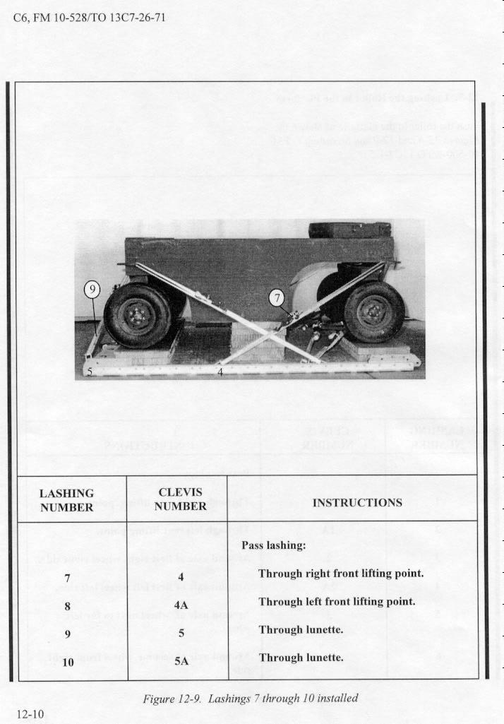
27 Lashing Number Clevis Number Instructions Pass lashing: A Through both bolt holes, and secure on top of tongue frame. Note: Pad top of tongue frame with cellulose wadding. Under lunette shaft.


28 Lashing Number Clevis Number Instructions Pass lashing: A 11 11A Through rear bolt hole. Around lunette shaft. Through front bolt hole. Around lunette shaft.

29
30

31 Lashing Number Clevis Number Instructions A 2 2A 3 3A 4 4A 5 5A 6 6A 7 7A 10 10A Pass lashing: Around frame, right side. Around frame, left side. Around rear side of center frame. Around rear side of center frame. Around rear side of center frame. Around rear side of center frame. Around end bar of frame, front. Around end bar of frame, front. Around end bar of frame, rear. Around end bar of frame, rear. Around front side of center frame. Around front side of center frame. Around front side of center frame. Around front side of center frame. Around end bar of frame, rear. Around end bar of frame, rear.

32
33
34

35
36
37
38 National Stock Number Item Quantity Adapter, coupling, EFTC Adhesive, paste, 1-gal As required Clevis, suspension, 1-in (large) Cloth, cotton duck, 60-in As required Cord, nylon, type III, 550-lb As required Coupling, airdrop, extraction force transfer with cable, 12-ft Cover: Clevis, large Link, type IV Cushioning material, packaging, cellulose wadding As required Leaf, extraction line (line bag) Line, drogue (for C-17) 60-ft (3-loop), type XXVI Line, extraction: 60-ft (3-loop), type XXVI (for C-130)(Use w/ 140-ft for C-5) 140-ft (3-loop), type XXVI (for C-141B,C-5, or C-17) 1 1 Link assembly: Type IV Two-point: Bolt, 1-in diam, 4-in long Nut, 1-in, hexagonal Plate, side, 5 1/2-in Spacer, large Lumber: 2- by 6- by 36-in 4- by 4- by 96-in Nail, steel wire, 8d As required 1 2
39 National Stock Number Item Quantity Pad, energy-dissipating (honeycomb) 3- by 36- by 96-in 20 sheets Parachute: Cargo: G-11B Cargo extraction: 22-ft Drogue (for C-17) 15-ft Platform, airdrop, type V, 12-ft Bracket assembly, coupling Clevis assembly, type V Extraction bracket assembly Tandem link assembly (Multipurpose link) (1) (22) (1) (4) Plywood, 3/4-in: 48- by 60-in 48- by 83-in 3 sheets (1) (2) Release, cargo parachute, M-1 1 Sling, cargo, airdrop For suspension: 16-ft (2-loop), type XXVI nylon webbing For lifting: 9-ft (2-loop), type XXVI nylon webbing For deployment: 9-ft (2-loop), type XXVI nylon webbing For riser extension: 20-ft (2-loop), type XXVI nylon webbing Strap, parachute release, multi-cut, comes w/ 3 knives Tape, adhesive, 2-in As required Tie-down assembly, 15-foot Webbing: Cotton, 1/4-in, type I Nylon, tubular, 1/2-in Type VIII As As As required required required
40
41
42
43
44
45
46
47
48
49
50
51
52

53
54
55
56
57
58
59
 is a fourcylinder, turbocharged, self-propelled diesel driven engine.")
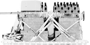
60 C7, FM /TO 13C CHAPTER 13 RIGGING THE VIBRATORY COMPACTOR (MODEL CS-433C) ON A 20-FOOT, TYPE V PLATFORM FOR LOW- VELOCITY AIRDROP Description of Load The vibratory compactor (Figure 13-1) is a fourcylinder, turbocharged, self-propelled diesel driven engine. This load is rigged on a 20-foot, type V platform with four G-11 cargo parachutes.the rigged weight of the vibratory compactor is 18,890 pounds. It is 262 inches long, 99 inches high with the roll over protection system removed, and 108 inches wide, when prepared for rigging Preparing the Platform Prepare a 20-foot, type V platform using two tandem multi-purpose links, four suspension links and 24 tiedown clevises as shown in Figure Figure Vibratory compactor (Model CS-433C) 13-1
61 C7, FM /TO 13C Left CLEVISES 12A THROUGH 1A Rear Front CLEVISES 12 THROUGH 1 Right Step: 1. Install a tandem multi-purpose link to each platform side rail using holes 1, 2, and Install a suspension link to each platform side rail using holes 6, 7, and Install a suspension link to each platform side rail using holes 33, 34, and Install a clevis on bushing 4 on each of the front tandem links. 5. Install a clevis on bushing 4 on each of the second suspension links. 6. Starting at the front of each platform side rail, install clevises on the bushings bolted on holes 4,17,18, 22, 25, 27, 37, 38, 39 and Starting at the front of the platform number the clevises 1 through 12 on the right side and 1A through 12A on the left side. 8. Label the tiedown rings according to FM /TO13C Note: The nose bumper may or may not be installed. Measurements given in this section are from the front edge of the platform, not the front edge of the nose bumper Figure Platform prepared

62 13-3. Preparing and Positioning Honeycomb Stacks C7, FM /TO 13C Prepare the honeycomb stacks as shown in Figures 13-3 through Position the honeycomb stacks on the platform as shown in Figure Stack 1 18 x 18 Stack 2 36 x 66 Stack Width Length Number Pieces (Inches) (Inches) Material Instructions Honeycomb Glue four pieces of honeycomb together to form a base /4-inch Glue plywood to the base Plywood and glue the remaining 18- inch by 18-inch piece of honeycomb on top of the plywood Honeycomb Glue the five pieces of honeycomb together to form a base /4-inch Glue plywood to the top of Plywood the base and glue the remaining piece of 36-inch by 66- inch honeycomb to the top of the plywood. Figure Honeycomb stacks 1 and 2 prepared 13-3


63 C7, FM /TO 13C x 25 Stack 3 12 x 60 Stack 4 24 x x 30 Stack Width Length Number Pieces (Inches) (Inches) Material Instructions Honeycomb Glue honeycomb together to form a base Honeycomb Glue pieces of honeycomb to the base aligned to the rear edge Honeycomb Glue each piece of honeycomb to the outer edge of the 12-inch by 60-inch piece of honey comb Honeycomb Glue eight pieces of honeycomb together to form a base /4-inch Glue the plywood to the base. Plywood Glue the remaining 16-inch by 30-inch piece of honeycomb on top of the plywood Figure Honeycomb stacks 3 and 4 prepared
 (Inches) Material Instructions 5 4 36 96 Honeycomb Glue pieces of honeycomb together to form a base.")

64 C7, FM /TO 13C Stack 5 36 x 96 2 x 4 x 36 Lumber 24 x 36 3/4-inch Plywood Stack 6 24 x x 36 Stack Width Length Number Pieces (Inches) (Inches) Material Instructions Honeycomb Glue pieces of honeycomb together to form a base Honeycomb Glue pieces of honeycomb together to form a base Honeycomb Center and glue to base /4-inch Position and nail ten pieces Plywood of lumber to the two pieces of plywood as shown in Figure x 4 36 Lumber Figure Honeycomb stacks 5 and 6 prepared 13-5

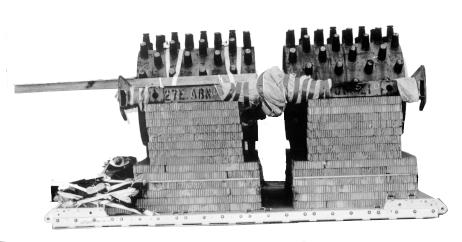
65 C7, FM /TO 13C Stack 6 Stack 3 Stack 5 Stack 4 Stack 2 Stack 1 Step: 1. Position stack 1 centered and flush with the front edge of the platform. 2. Position stack 2 centered and 18 inches from stack Position stack 3 centered and flush against stack Position stack 4 centered and flush against stack Position stack 5 centered and 19 inches from stack Position stack 6 centered and flush against stack Figure Honeycomb stacks positioned on platform

66 13-4. Preparing and Positioning Vibratory Compactor on Platform C7, FM /TO 13C Prepare and position the vibratory compactor on a platform as shown in Figures 13-7 and Remove the roll over protection system and tape all lights and reflectors. 2 Tape cellulose wadding to all lashing tiedown points. Figure Vibratory compactor prepared 13-7


67 C7, FM /TO 13C Tape cellulose wadding to the upper pivot arm of the chassis. 4 Tape cellulose wadding to the hydraulic attaching point of the blade Figure Vibratory compactor prepared (continued)


68 C7, FM /TO 13C Remove the air-filter and exhaust pipe. Secure them to convenient points in the cab. 6 Lower the seat and lock it down. 7 Tape felt on the upper portions of the rear wheel wells where the slings will make contact. 8 Tape the edges of a 29-inch by 38-inch piece of honeycomb and secure it on top of the engine compartment with type III nylon cord tied to a convenient point on the load. Figure Vibratory compactor prepared (continued) 13-9
69 C7, FM /TO 13C /4-inch Plywood 52 3/4-inch Plywood 36 9 Tie a 28-inch by 42-inch piece of 3/4-inch plywood flush with a 36-inch by 52-inch piece of 3/4-inch plywood using type III nylon cord. Tape cellouse wadding to the outer edges of plywood Figure Vibratory compactor prepared (continued)

70 C7, FM /TO 13C Using 1/2-inch tubular nylon, secure the plywood to the cab of the vibratory compactor and to a convenient point on the load. Figure Vibratory compactor prepared (continued) 13-11

. 3 Tape felt on the top edges of the roller.")
71 C7, FM /TO 13C Stack 6 Stack 2 2 Inches Position the roller on the honeycomb aligning the front edge of the blade 2 inches from the front edge of the platform. 2 Make sure the bolts under the rear engine compartment are aligned between the 4th and 5th pieces of 2 x 4 x 36-inch lumber on stack 6 (not shown). 3 Tape felt on the top edges of the roller. 4 Secure the blade control with type III nylon cord to the fuse box hinge Figure Vibratory compactor positioned on platform


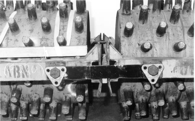
72 13-5. Lashing Vibratory Compactor to Platform C7, FM /TO 13C Lash the vibratory compactor to the platform as shown in Figures 13-9 through and FM /TO 13C Tiedown 2 Tiedown 1 Hydraulic Attaching Point Lashing Clevis Number Number Instructions Pass lashing: 1 2 Around right hydraulic attaching point of blade. 2 2A Around left hydraulic attaching point of blade. 3 1 Through tie-down number 2, right side. 4 1A Through tie-down number 2, left side. 5 3 Through tie-down number 1, right side. 6 3A Through tie-down number 1, left side. Figure Lashings 1 through 6 installed 13-13


73 C7, FM /TO 13C Upper pivot arm 7 Tie-down 4 Tie-down Tie-down Lashing Clevis Number Number Instructions Pass lashing: 7 4 Around upper pivot arm of chassis, right side. 8 4A Around upper pivot arm of chassis, left side. 9 5 Through tie-down number 3, right side. 10 5A Through tie-down number 3, left side Through tie-down number 4, right side. 12 6A Through tie-down number 4, left side Through tie-down number 2, right side. 14 7A Through tie-down number 2, left side Figure Lashings 7 through 14 installed

74 C7, FM /TO 13C Tie-down 4 Tie-down 3 Rear Tie-down Lashing Clevis Number Number Instructions Pass lashing: 15 9 Through rear tie-down, left side. 16 9A Through rear tie-down, right side Through tie-down number 3, right side A Through tie-down number 3, left side Through tie-down number 4, right side A Through tie-down number 4, left side. Figure Lashings 15 through 20 installed 13-15
, type XXVI nylon webbing slings to the tandem links as shown in Figure 13-12.")


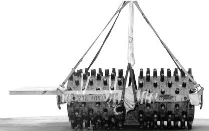
75 C7, FM /TO 13C Installing and Safetying Suspension Slings and Deadman s Tie Install and safety four 16-foot (4-loop), type XXVI nylon webbing slings to the tandem links as shown in Figure Rear Front Place a large clevis in one end of a 16-foot (4-loop), type XXVI nylon suspension sling. Attach another large clevis to the front right and front left suspension links. Attach the large clevises together and safety-tie them with type III nylon cord in an hourglass configuration. 2 Place a 5 1/2-inch two point link in one end of a 16-foot (4-loop), type XXVI nylon suspension sling. Pass a 3-foot (4-loop), type XXVI nylon sling through the two point link and fold in half. Attach both running ends of the 3-foot sling to a large clevis. Attach the large clevis to the rear right and rear left suspension links. Tape a piece of felt to the 5 1/2-inch two point link. 3 Raise the slings and install the deadman s tie on the front and rear sets of slings IAW FM /TO 13C Tape a piece of felt on the front slings, starting at a point 18 inches above the clevis to 18 inches above the roller. 5 Tie the rear slings to the padded and taped portions of the wheel well using type III nylon cord. Figure Suspension slings and deadman s tie installed 13-16

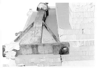
76 13-7. Building and Positioning Parachute Stowage Platform C7, FM /TO 13C Build and position the parachute stowage platform as shown in Figure Cut and glue 13 layers of 23-inch by 50-inch pieces of honeycomb together to form the base. 2 Cut a channel in the bottom layer of the honeycomb that will allow the extraction bracket to fit under it. 3 Cut and glue two layers of 36-inch by 50-inch pieces of honeycomb together on top of the base and flush with the front edge. 4 Tape the outer edges of the 26-inch by 50-inch pieces of honeycomb and position it on the platform centered and flush with the rear edges. Secure it to the platform with 1/2-inch tubular nylon webbing to deck-rings 10A and 10D. Figure Parachute stowage platform built and positioned 13-17

77 C7, FM /TO 13C Cut and glue three layers of 36-inch by 71-inch pieces of honeycomb centered on top of the base Figure Parachute stowage platform built and positioned (continued)

78 C7, FM /TO 13C x 6 x 71 Lumber x 71 Honeycomb 3/4 Plywood 24 2 x 6 x 71 Lumber 2 x 6 x 48 Lumber 6 2 x 6 x 48 Lumber 6 Construct a parachute stowage platform using two pieces of 2-inch by 6-inch by 71-inch lumber, two pieces of 2-inch by 6-inch by 48-inch lumber, one piece of 48-inch by 82-inch plywood, and one piece of 23-inch by 71-inch honeycomb. Figure Parachute stowage platform built and positioned (continued) 13-19

79 C7, FM /TO 13C Place the parachute stowage platform on the honeycomb stack. Secure it by routing a 15-foot lashing from clevis 8 to the front right hole to the center hole. Secure with a load binder. Route a 15-foot lashing from clevis 8A to the front left hole to the center hole and secure with a loadbinder. 8 Route a 15-foot lashing from clevis 10 to the center hole to the rear hole and secure with a loadbinder. Route a 15-foot lashing from clevis 10A to the center hole to the rear hole and secure with a loadbinder Figure Parachute stowage platform built and positioned (continued)

80 13-8. Installing Cargo Parachutes C7, FM /TO 13C Install four G-11 cargo parachutes on the load according to FM / TO 13C7-1-5 and as shown in Figure Prepare and stow four G-11 cargo parachutes in accordance with FM / TO 13C Restrain the parachutes using bushings 40, 40A, and 36, 36A on the platform. Figure Parachutes stowed 13-21


81 C7, FM /TO 13C Installing Extraction System Install the EFTC system according to FM /TO 13C7-1-5 and as shown in Figure Install the components of the extraction force transfer coupling (EFTC) according to FM /TO 13C Use the rear mounting holes for the EFTC bracket. 2 Secure a 16-foot EFTC cable with type I, 1/4-inch cotton webbing to a convenient point on the platform. 3 Attach a 9-foot (2-loop), type XXVI nylon sling to be used as a deployment line Figure EFTC installed

82 Installing Parachute Release C7, FM /TO 13C Install an M-2 cargo parachute release according to FM /TO 13C7-1-5 and as shown in Figure Cut and position a 29-inch by 38-inch piece of honeycomb on the engine compartment and secure it with type III nylon cord. 2 Attach the suspension slings and the riser extensions to the M-2 release according to FM /TO 13C Secure the release to the platform with type III nylon cord. 3 S-fold the suspension slings and tie the folds with type I, 1/4-inch cotton webbing. Figure M-2 release installed 13-23
83 C7, FM /TO 13C Installing Provisions for Emergency Restraints Select and install provisions for emergency restraints according to the emergency aft restraint requirements table in FM / TO 13C Placing Extraction Parachute Select the extraction parachute and extraction line needed using the extraction line requirements table in FM /TO 13C Place the extraction parachute and extraction line on the load for installation in the aircraft Marking Rigged Load Mark the rigged load according to FM /TO 13C7-1-5 and as shown in Figure If the load varies from the one shown, the weight, height, CB, tip-off curve, and parachute requirment must be recomputed Equipment Required Use the equipment list in Table 13-1 to rig this load
.")
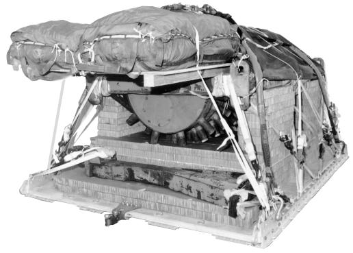
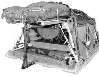
84 C7, FM /TO 13C Make the final rigger inspection required by FM /TO13C7-1-5 before the load leaves the rigging site. CB RIGGED LOAD DATA WEIGHT...18,890 Pounds MAXIMUM WEIGHT...20,000 Pounds HEIGHT...99 Inches WIDTH Inches LENGTH Inches OVERHANG...Front: 0 Inches Rear: 22 Inches CB (from the front edge of platform) Inches Extraction System (adds 18 inches to length of platform) Figure Vibratory compactor (Model CS-433C) rigged on a type V platform 13-25
85 C7, FM /TO 13C Table Equipment required for rigging vibratory compactor (Model CS-433C) for lowvelocity airdrop on a type V platform National Stock Number Item Quantity Adhesive, paste, 1-gal As Required Clevis, suspension, 1-in (large) Clevis, emergency restraints, (med) Cloth, cotton duck, 60-in As Required Cord, nylon III, 550-lb As Required Coupling, airdrop, extraction force transfer with cable, 20ft 1 Cover: Clevis, large Link, type IV Cushioning material, packaging,cellulose wadding As Required Felt 1/2-inch As Required Leaf, extraction line, (line bag) 2 Line, extraction: ft (3-loop), type XXVI (for C130) ft (3-loop), type XXVI (for C141, C5, and C17) Line, drogue (C17) 60-ft (1-loop), type XXVI 1 Suspension: ft (4-loop), type XXVI ft (4-loop), type XXVI 2 Link assembly: Two-point, 5 1/2-in Type IV
86 C7, FM /TO 13C Table Equipment required for rigging vibratory compactor (Model CS-433C) for lowvelocity airdrop on a type V platform (continued) National Stock Number Item Quantity Nail, steel wire, common, 6d As required Pad, energy-dissipating (honeycomb) 28 sheets Plywood, 3/4-in 2 sheets Lumber, 2 by 4-in As required Parachute: Cargo: G-11B 4 Cargo Extraction ft Drogue, 15-ft (C17) 1 Platform, airdrop, type V, 20ft Bracket assembly, coupling Clevis assembly, type V Extraction bracket assembly Suspension link Tandem Link Release, cargo parachute, M-2 1 Sling, cargo, airdrop For deployment: ft (2-loop), type XXVI nylon webbing 1 For extension: ft (3-loop), type XXVI nylon webbing ft (4-loop), type XXVI nylon webbing
87 C7, FM /TO 13C Table Equipment required for rigging vibratory compactor (Model CS-433C) for lowvelocity airdrop on a type V platform (continued) National Stock Number Item Quantity Knife, multi, strap, parachute release Tape, PSA, cloth back, 2-in As required Tiedown assembly, 15-ft 28 Webbing: Cotton, 1/4-in, type I As required Nylon, tubular, 1/2-in As required Type VIII As required 13-28
 is a fourcylinder, turbocharged, selfpropelled diesel driven engine, and uses a single sheep-foot drum with an optional leveling blade.")
88 C7, FM /TO 13C CHAPTER 14 RIGGING THE VIBRATORY COMPACTOR (MODEL CS-433P) ON A 20-FOOT, TYPE V PLATFORM FOR LOW-VELOCITY AIRDROP Description of Load The vibratory compactor (Figure 14-1) is a fourcylinder, turbocharged, selfpropelled diesel driven engine, and uses a single sheep-foot drum with an optional leveling blade. This load is rigged on a 20-foot, type V platform with four G-11 cargo parachutes. The rigged weight of the vibratory compactor is 19,147 pounds. It is 262 inches long, 99 inches high, and 108 inches wide, when prepared for rigging Preparing the Platform Prepare a 20-foot, type V platform using two tandem multi-purpose links, four suspension links and 24 tiedown clevises as shown in Figure Figure Vibratory compactor (Model CS-433P) 14-1
89 C7, FM /TO 13C Left CLEVISES 12A THROUGH 1A Rear Front CLEVISES 12 THROUGH 1 Right Step: 1. Install a tandem multi-purpose link to each plaform side rail using holes 1, 2, and Install a suspension link to each platform side rail using holes 6, 7, and Install a suspension link to each platform side rail using holes 33, 34, and Install a clevis on bushing 4 on each of the front tandem links. 5. Install a clevis on bushing 4 on each of the second suspension links. 6. Starting at the front of each platform side rail, install clevises on the bushings bolted on holes 4, 17, 18, 22, 25, 27, 37, 38, 39 and Starting at the front of the platform number the clevises 1 through 12 on the right side and 1A through 12A on the left side. 8. Label the tiedown rings according to FM /TO 13C Note: The nose bumper may or may not be installed. Measurements given in this section are from the front edge of the platform, not the front edge of the nose bumper Figure Platform prepared
90 14-3. Preparing and Positioning Honeycomb Stacks C7, FM /TO 13C Prepare the honeycomb stacks as shown in Figures 14-3 through Position the honeycomb stacks on the platform as shown in Figure Stack 1 Stack 2 18 x x 66 Stack Width Length Number Pieces (Inches) (Inches) Material Instructions Honeycomb Glue four pieces of honeycomb together to form a base /4-inch Glue plywood to the base Plywood and glue the remaining 18- inch by 18-piece of honey comb on top of the plywood Honeycomb Glue four pieces of honeycomb together to form a base /4-inch Glue plywood to the top of Plywood the base and glue the remaining piece of 36-inch by 66- inch honeycomb to the top of the plywood. Figure Honeycomb stacks 1 and 2 prepared 14-3

91 C7, FM /TO 13C Stack 3 12 x 25 Stack 4 12 x x x 30 Stack Width Length Number Pieces (Inches) (Inches) Material Instructions Honeycomb Glue honeycomb together to form a base Honeycomb Glue pieces of honeycomb to the base aligned on the rear edge Honeycomb Glue each piece of honeycomb to the outer edge of the 12-inch by 60-inch piece of honeycomb Honeycomb Glue eight pieces of honeycomb together to form a base /4-inch Glue the plywood to the Plywood top of the base. Glue the remaning piece of honeycomb to the top of the plywood Figure Honeycomb stacks 3 and 4 prepared


92 Stack 5 C7, FM /TO 13C x 96 2 x 4 x 36 Lumber 18 x 36 3/4-inch Plywood Stack 6 18 x x 36 Stack Width Length Number Pieces (Inches) (Inches) Material Instructions Honeycomb Glue pieces of honeycomb together to form a base Honeycomb Glue pieces of honeycomb together to form a base Honeycomb Center and glue to base /4-inch Nail three pieces of 3/4-inch Plywood plywood together. 6 2 x 4 36 Lumber Nail two pieces of lumber to the rear edge of the plywood and two more pieces centered on the plywood. Glue the piece on top of the 18-inch by 36-inch piece of honeycomb. Figure Honeycomb stacks 5 and 6 prepared 14-5

93 C7, FM /TO 13C Stack 6 Stack 5 Stack 3 Stack 4 Stack 2 Stack 1 Step: 1. Position stack 1 centered and flush with the front edge of the platform and not the nose bumper if present. 2. Position stack 2 centered and 18 inches from stack Position stack 3 centered and flush against stack Position stack 4 centered and flush against stack Position stack 5 centered and 19 inches from stack Position stack 6 centered and 1 inch from stack Figure Honeycomb stacks positioned on platform


94 14-4. Preparing and Positioning Vibratory Compactor on Platform C7, FM /TO 13C Prepare and position the vibratory compactor on a platform as shown in Figures 14-7 and Tape all lights and reflectors. 2 Tape cellulose wadding to all lashing tiedown points. Figure Vibratory compactor prepared 14-7


95 C7, FM /TO 13C Tape cellulose wadding to the upper pivot arm of the chassis. 4 Tape cellulose wadding to the hydraulic attaching point of the blade Figure Vibratory compactor prepared (continued)


96 C7, FM /TO 13C Remove the air-filter and exhaust pipe. Secure them to convenient points in the cab. 6 Lower the seat and lock it down. Figure Vibratory compactor prepared (continued) 14-9

97 C7, FM /TO 13C Tape felt on the upper portions of the rear wheel wells where the slings will make contact. 8 Tape the edges of a 29-inch by 38-inch piece of honeycomb and secure it on top of the engine compartment with type III nylon cord tied to a convenient point on the roller Figure Vibratory compactor prepared (continued)
98 C7, FM /TO 13C /4-inch Plywood Type III nylon cord 51 3/4-inch Plywood 39 9 Tie a 24-inch by 39-inch piece of 3/4-inch plywood to a 39-inch by 51-inch piece of 3/4-inch plywood using type III nylon cord as shown. Figure Vibratory compactor prepared (continued) 14-11

99 C7, FM /TO 13C Using 1/2-inch tubular nylon, secure the piece of plywood to the cab of the vibratory compactor to a convenient point on the load Figure Vibratory compactor prepared (continued)
100 C7, FM /TO 13C inches Stack 2 1 Position the vibratory compactor with the roller on honeycomb stack 2 aligning the front edge of the blade 2 inches from the front edge of the platform. Figure Vibratory compactor positioned on platform 14-13


101 C7, FM /TO 13C Lashing Vibratory Compactor to the Platform Lash the vibratory compactor to the platform as shown in Figures 14-9 through and FM /TO 13C Tiedown 2 Tiedown Lashing Clevis Number Number Instructions Pass lashing: 1 2 Around right hydraulic attaching point of blade. 2 2A Around left hydraulic attaching point of blade. 3 1 Through tie-down number 2, right side. 4 1A Through tie-down number 2, left side. 5 3 Through tie-down number 1, right side. 6 3A Through tie-down number 1, left side Figure Lashings 1 through 6 installed

102 C7, FM /TO 13C Lashing Clevis Number Number Instructions Pass lashing: 7 4 Around right upper pivot arm of chassis. 8 4A Around left upper pivot arm of chassis. 9 5 Through tie-down number 3, right side. 10 5A Through tie-down number 3, left side Through tie-down number 4, right side. 12 6A Through tie-down number 4, left side Through tie-down number 2, right side 14 7A Through tie-down number 2, left side. Figure Lashings 7 through 14 installed 14-15

103 C7, FM /TO 13C Tiedown 4 Tiedown Lashing Clevis Number Number Instructions Pass lashing: 15 9 Through rear tie-down, left side. 16 9A Through rear tie-down, right side Through clevis 11 to tie-down number 3, left side A Through clevis 11A to tie-down number 3, right side Through clevis 12 to tie-down number 4, left side A Through clevis 12A to tie-down number 4, right side Figure Lashings 15 through 20 installed
, type XXVI nylon suspension sling.")
, type XXVI nylon suspension sling. Pass a 3-foot (4-loop), type XXVI nylon sling through the two point link and fold in half.")

104 14-6. Installing and Safetying Suspension Slings and Deadman s Tie C7, FM /TO 13C Install and safety four 16-foot (4-loop), type XXVI nylon webbing slings to the tandem links as shown in Figure Rear 3 Front Place a large clevis in one end of a 16-foot (4-loop), type XXVI nylon suspension sling. Attach another large clevis to the front right and front left suspension links. Attach the large clevises together and safety-tie them with type III nylon cord in an hourglass configuration. 2 Place a 5 1/2-inch two point link in one end of a 16-foot (4-loop), type XXVI nylon suspension sling. Pass a 3-foot (4-loop), type XXVI nylon sling through the two point link and fold in half. Attach both running ends of the 3-foot sling to a large clevis. Attach the large clevis to the rear right and rear left suspension links. Tape a piece of felt to the 5 1/2-inch two point link. 3 Raise the slings and install the deadman s tie on the front and rear sets of slings IAW FM /TO 13C Tape a piece of felt on the front slings, starting at a point 18 inches above the clevis to 18 inches above the roller and tie to a conveniewnt point. 5 Tie the rear slings to the padded and taped portions of the wheel well using type III nylon cord. Figure Suspension slings and deadman s tie installed 14-17


105 C7, FM /TO 13C Building and Positioning Parachute Stowage Platform Build and position the parachute stowage platform as shown in Figure Cut and glue 13 layers of 23-inch by 50-inch pieces of honeycomb together to form the base on the platform. 2 Cut a channel in the bottom layer of honeycomb that will allow the extraction bracket to fit under it. 3 Cut and glue two layers of 26-inch by 50-inch pieces of honeycomb together on top of the base and flush with the front edge. 4 Tape the outer edges of the 26-inch by 50-inch piece of honeycomb and position it on the platform centered and flush with the rear edge. Secure it to the platform with 1/2-inch tubular nylon webbing to deck-rings 10A and 10D. 5 Cut and glue three layers of 36-inch by 71-inch pieces of honeycomb centered on top of the base Figure Parachute stowage platform constructed and positioned

106 C7, FM /TO 13C Contsruct a parachute stowage platform as shown in Figure 13-13, step 6. 7 Place the parachute stowage platform on the honeycomb stack. Secure it by routing a 15-foot lashing from clevis 10 to the front right hole to the center hole. Secure with a load binder. Route a 15-foot lashing from clevis 10A to the front left hole to the center hole and secure with a loadbinder. 8 Route a 15-foot lashing from clevis 8 to the center hole to the rear hole and secure with a load binder. Route a 15-foot lashing from clevis 8A to the center hole to the rear hole and secure with a loadbinder. Figure Parachute stowage platform constructed and positioned (continued) 14-19


107 C7, FM /TO 13C Installing Cargo Parachutes Install four G-11 cargo parachutes on the load according to FM / TO 13C7-1-5 and as shown in Figure Prepare and stow four G-11 cargo parachutes in accordance with FM / TO 13C Restrain the parachutes using bushings 40, 40A, 36, and 36A on the platform Figure Parachutes stowed


108 14-9. Installing Extraction System C7, FM /TO 13C Install the EFTC system according to FM /TO 13C7-1-5 and as shown in Figure Install the components of the extraction force transfer coupling (EFTC) according to FM /TO13C Use the rear mounting holes for the EFTC bracket. 2 Secure a 16-foot EFTC cable with type I, 1/4-inch cotton webbing to a convenient point on the platform. 3 Attach a 9-foot (2-loop), type XXVI nylon sling to be used as a deployment line. Figure EFTC installed 14-21

109 C7, FM /TO 13C Installing Parachute Release Install an M-2 cargo parachute release according to FM /TO 13C7-1-5, and as shown in Figure Attach the suspension slings and the riser extensions to the M-2 release according to FM /TO 13C Secure the release to the platform with type III nylon cord. 2 S-fold the suspension slings and tie the folds with type I, 1/4-inch cotton webbing Figure M-2 release installed
110 C7, FM /TO 13C Installing Provisions for Emergency Marking Rigged Load Restraints Mark the rigged load according to FM Select and install provisions for emergency /TO 13C7-1-5 and as shown in restraints according to the emergency aft Figure restraint requirements table in FM / TO 13C Equipment Required Placing Extraction Parachute Use the equipment list in Table 14-1 to rig this load. Select the extraction parachute and extraction line needed using the extraction line requirements table in FM /TO 13C Place the extraction parachute and extraction line on the load for installation in the aircraft
.")
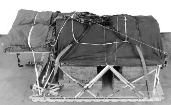
111 C7, FM /TO 13C Make the final rigger inspection required by FM /TO 13C7-1-5 before the load leaves the rigging site. CB RIGGED LOAD DATA WEIGHT...19,147 Pounds MAXIMUM WEIGHT...21,000 Pounds HEIGHT...99 Inches WIDTH Inches LENGTH Inches OVERHANG...Front: 0 Inches Rear: 22 Inches CB (from the front of platform) inches Extraction System (adds 18 inches to length of platform) Figure Vibratory compactor (model CS-433P) rigged on a type V platform
112 C7, FM /TO 13C Table Equipment required for rigging vibratory compactor (Model CS-433P) for lowvelocity airdrop on a type V platform National Stock Number Item Quantity Adhesive, paste, 1-gal As required Clevis, suspension, 1-in (large) Clevis, emergency restraints, (med) Cloth, cotton duck, 60-in As required Cord, nylon III, 550-lb As required Coupling, airdrop, extraction force transfer with cable, 20ft 1 Cover: Clevis, large Link, type IV Cushioning material, packaging,cellulose wadding As required Felt 1/2-inch As required Leaf, extraction line, (line bag) 2 Line, extraction: ft (3-loop), type XXVI (for C130) ft (3-loop), type XXVI (for C141, C5, and C17) Line, drogue (C17) 60-ft (1-loop), type XXVI 1 Suspension: ft (4-loop), type XXVI ft (4-loop), type XXVI 2 Link assembly: Type IV Two-point, 5 1/2-in
113 C7, FM /TO 13C Table Equipment required for rigging vibratory compactor (Model CS-433P) for lowvelocity airdrop on a type V platform (continued) National Stock Number Item Quantity Nail, steel wire, common, 6d As required Pad, energy-dissipating (honeycomb) 28 sheets Plywood, 3/4-in 2 sheets Lumber, 2 by 4-in As required Parachute: Cargo: G-11B 4 Cargo Extraction ft Drogue, 15-ft (C17) 1 Platform, airdrop, type V, 20ft Bracket assembly, compoent, EFTC Clevis assembly, type V Extraction bracket assembly Suspension link Tandem Link Release, cargo parachute, M-2 1 Sling, cargo, airdrop Suspension and lifting: ft (4-loop),type XXVI nylon webbing 4 For deployment: ft (2-loop), type XXVI nylon webbing 1 For extension: ft (3-loop), type XXVI nylon webbing ft (4-loop), type XXVI nylon webbing
114 C7, FM /TO 13C Table Equipment required for rigging vibratory compactor (Model CS-433P) for lowvelocity airdrop on a type V platform (continued) National Stock Number Item Quantity Link, assembly, coupling, 3-point Knife, multi, strap, parachute release Tape, PSA, cloth back, 2-in As required Tiedown assembly, 15-ft 28 Webbing: Cotton, 1/4-in, type I As required Nylon, tubular, 1/2-in As required Type VIII, OD As required 14-27
115 C7, FM TO 13C By Order of the Secretary of the Army: Official: ERIC K. SHINSEKI General, United States Army Chief of Staff JOEL B. HUDSON Administrative Assistant to the Secretary of the Army DISTRIBUTION: Active Army, Army National Guard, and U. S. Army Reserve: To be distributed in accordance with the initial distribution number , requirements for FM
116 PIN:
RIGGING ROAD ROLLERS C7, FM /TO 13C
 RIGGING ROAD ROLLERS C7, FM 10-528/TO 13C7-26-71 C7, FM 10-528 TO 13C7-26-71 By Order of the Secretary of the Army: Official: ERIC K. SHINSEKI General, United States Army Chief of Staff JOEL B. HUDSON
AIRDROP OF SUPPLIES AND EQUIPMENT: RIGGING FUEL DRUMS
 AIRDROP OF SUPPLIES AND EQUIPMENT: RIGGING FUEL DRUMS DISTRIBUTION RESTRICTION: Approved for public release; distribution is unlimited. HEADQUARTERS DEPARTMENTS OF THE ARMY AND THE AIR FORCE CHANGE NO.
AIRDROP OF SUPPLIES AND EQUIPMENT: RIGGING FORWARD AREA REFUELING EQUIPMENT (FARE) AND ADVANCED AVIATION FORWARD AREA REFUELING SYSTEM (AAFARS)
 AND ADVANCED AVIATION FORWARD AREA REFUELING SYSTEM (AAFARS)") FM 4-0.37 (FM 0-537) AIR FORCE TO 3C7--9 AIRDROP OF SUPPLIES AND EQUIPMENT: RIGGING FORWARD AREA REFUELING EQUIPMENT (FARE) AND ADVANCED AVIATION FORWARD AREA REFUELING SYSTEM (AAFARS) JUNE 003 DISTRIBUTION
FM 4-0.37 (FM 0-537) AIR FORCE TO 3C7--9 AIRDROP OF SUPPLIES AND EQUIPMENT: RIGGING FORWARD AREA REFUELING EQUIPMENT (FARE) AND ADVANCED AVIATION FORWARD AREA REFUELING SYSTEM (AAFARS) JUNE 003 DISTRIBUTION
6-6. Install the lashings and secure pre-positioned lashings as shown in Figures 6-8 through 6-15.
 Chapter 6 LOADING AND CLOSING THE BOXES 6-5. Load and close the boxes as described below. Use the tiedown rings inside the box to secure the load, if necessary. Use honeycomb, if necessary, to cover the
AIRDROP OF SUPPLIES AND EQUIPMENT: RIGGING COMMUNICATION CONTROL VEHICLES
 AIRDROP OF SUPPLIES AND EQUIPMENT: RIGGING COMMUNICATION CONTROL VEHICLES DISTRIBUTION RESTRICTION: Approved for public release; distribution is unlimited. HEADQUARTERS DEPARTMENT OF THE ARMY DEPARTMENT
Headquarters Department of the Army Department of the Air Force
 FM 4-20.121(FM 4-20.121 and FM 10-539) TO 13C7-6-21 Airdrop of Supplies and Equipment: Rigging Tractors and Tractor-Dozers September 2007 DISTRIBUTION RESTRICTION. Approved for public release; distribution
AIRDROP OF SUPPLIES AND EQUIPMENT: RIGGING HIGH-MOBILITY MULTIPURPOSE WHEELED VEHICLES
 HEADQUARTERS DEPARTMENT OF THE ARMY UNITED STATES MARINE CORPS DEPARTMENT OF THE AIR FORCE CHANGE NO. 1 Washington, DC, AIRDROP OF SUPPLIES AND EQUIPMENT: RIGGING HIGH-MOBILITY MULTIPURPOSE WHEELED VEHICLES
RIGGING HIGH-MOBILITY MULTIPURPOSE WHEELED VEHICLES
 ARMY FM 4-20.117 (FM 10-517) AIR FORCE TO 13C7-1-111 AIRDROP OF SUPPLIES AND EQUIPMENT: RIGGING HIGH-MOBILITY MULTIPURPOSE WHEELED VEHICLES HEADQUARTERS DEPARTMENT OF THE ARMY DEPARTMENT OF THE AIR FORCE
RIGGING HIGH-MOBILITY MULTIPURPOSE WHEELED VEHICLES
 ARMY FM 4-20.117 (FM 10-517) AIR FORCE TO 13C7-1-111 AIRDROP OF SUPPLIES AND EQUIPMENT: RIGGING HIGH-MOBILITY MULTIPURPOSE WHEELED VEHICLES HEADQUARTERS DEPARTMENT OF THE ARMY DEPARTMENT OF THE AIR FORCE
Manual Provided by emilitary Manuals -
 ARMY FM 4-20 116 (FM 10-516) AIR FORCE TO 13C7-1-13 AIRDROP OF SUPPLIES AND EQUIPMENT: Reference Data for Airdrop Platform Loads DISTRIBUTION RESTRICTION: Approved for public release; distribution is unlimited
19 Pad the face of the PDB and the PLU with cellulose wadding taped in place.
 21 20 19 19 Pad the face of the PDB and the PLU with cellulose wadding taped in place. 20 Place a 17- by 19 1/2-inch piece of honeycomb on top of the PLU. Crush the honeycomb to allow for the printer mount
Headquarters Department of the Army Department of the Air Force
 FM 4-20.116 TO 13C7-1-13 Airdrop of Supplies and Equipment: Reference Data for Airdrop Platform Loads MAY 2006 DISTRIBUTION RESTRICTION: Approved for public release; distribution is unlimited Headquarters
AIR TRANSPORTABILITY GUIDANCE TWO M151 1/4-TON TRUCKS AND ONE 1/4-TON TRAILER IN CH-47 HELICOPTER
 TM -2320-218-10-3 DEPARTMENT OF THE ARMY TECHNICAL MANUAL AIR TRANSPORTABILITY GUIDANCE TWO M11 1/4-TON TRUCKS AND ONE 1/4-TON TRAILER IN CH-47 HELICOPTER Headquarters, Department of the Army, Washington,
The U.S. Army Pathfinder School Nomenclature
 The U.S. Army Pathfinder School Nomenclature Common Sling Load Equipment Note: Students are required to know both proper nomenclature and all rated capacities. Information (in parenthesis) is not testable.
AIR TRANSPORTABILITY GUIDANCE M151 1/4-TON TRUCK AND M100 1/4-TON TRAILER IN CH-17 HELlCOPTER
 TM 55-2320-218-10-2 DEPARTMENT OF THE ARMY TECHNICAL MANUAL AIR TRANSPORTABILITY GUIDANCE M151 1/4-TON TRUCK AND M100 1/4-TON TRAILER IN CH-17 HELlCOPTER Headquarters, Department of the Army, Washington,
ARNG WTC Pathfinder MTT. Common Slingload Equipment
 ARNG WTC Pathfinder MTT Slingloads Nomenclature Packet Common Slingload Equipment Note: Students are required to know both proper nomenclature and all rated capacities. Information (in parenthesis) is
TECHNICAL MANUAL TRANSPORTABILITY GUIDANCE GRADER, ROAD, MOTORIZED, DIESEL-ENGINE-DRIVEN (DED) HEAVY, COMMERCIAL CONSTRUCTION EQUIPMENT (CCE)
 HEAVY, COMMERCIAL CONSTRUCTION EQUIPMENT (CCE)") TECHNICAL MANUAL TRANSPORTABILITY GUIDANCE GRADER, ROAD, MOTORIZED, DIESEL-ENGINE-DRIVEN (DED) HEAVY, COMMERCIAL CONSTRUCTION EQUIPMENT (CCE) MODEL 130G MIL NSN 3805-01-150-4795 MODEL 130G TYPE I (NONSECTIONALIZED)
TECHNICAL MANUAL TRANSPORTABILITY GUIDANCE GRADER, ROAD, MOTORIZED, DIESEL-ENGINE-DRIVEN (DED) HEAVY, COMMERCIAL CONSTRUCTION EQUIPMENT (CCE) MODEL 130G MIL NSN 3805-01-150-4795 MODEL 130G TYPE I (NONSECTIONALIZED)
AIR TRANSPORTABILITY GUIDANCE TWO M151 1/4-TON TRUCKS AND ONE 1/4-TON TRAILER IN CH-47 HELICOPTER
 TM -2320-218-10-3 DEPARTMENT OF THE ARMY TECHNICAL MANUAL AIR TRANSPORTABILITY GUIDANCE TWO M11 1/4-TON TRUCKS AND ONE 1/4-TON TRAILER IN CH-47 HELICOPTER Headquarters, Department of the Army, Washington,
TRANSPORT GUIDANCE TRUCK 5-TON, 6X6 M939-SERIES/M939A1-SERIES/M939A2-SERIES HEADQUARTERS, DEPARTMENT OF THE ARMY TM
 TRANSPORT GUIDANCE TRUCK 5-TON, 6X6 M939-SERIES/M939A1-SERIES/M939A2-SERIES APPROVED FOR PUBLIC RELEASE DISTRIBUTION IS UNLIMITED HEADQUARTERS, DEPARTMENT OF THE ARMY SEPTEMBER 1993 Description M939-Series
TM &P TECHNICAL MANUAL
 TECHNICAL MANUAL OPERATOR S, ORGANIZATIONAL, DIRECT SUPPORT, AND GENERAL SUPPORT MAINTENANCE MANUAL (INCLUDING REPAIR PARTS AND SPECIAL TOOLS LISTS) FOR TM 9-2330-359-14&P SEMITRAILER, FLATBED: BREAKBULK/CONTAINER
1 1/2-TON, 2-WHEEL, M332 PAGE B1 (NSN ) REPAIR PARTS AND SPECIAL TOOLS LIST PAGE F-1
 REPAIR PARTS AND SPECIAL TOOLS LIST PAGE F-1") TECHNICAL MANUAL OPERATOR'S, ORGANIZATIONAL, DIRECT SUPPORT, AND GENERAL SUPPORT MAINTENANCE (INCLUDING REPAIR PARTS AND SPECIAL TOOLS LIST) OPERATING INSTRUCTIONS PAGE 2-1 OPERATOR PMCS PAGE 2-4 OPERATOR
TECHNICAL MANUAL OPERATOR'S, ORGANIZATIONAL, DIRECT SUPPORT, AND GENERAL SUPPORT MAINTENANCE (INCLUDING REPAIR PARTS AND SPECIAL TOOLS LIST) OPERATING INSTRUCTIONS PAGE 2-1 OPERATOR PMCS PAGE 2-4 OPERATOR
(?6 (A 25' V 0^7 AIR TRANSPORT PROCEDURES TRANSPORT OF SPARTAN WARHEAD SECTION IN SHIPPING AND STORAGE CONTAINER, XM553, BY CH-47 HELICOPTER
 (?6 (A 2' V 0^7 ( Ref«re nc8 DEPARTMENT OF THE ARMY FM -700 FIELD MANUAL AIR TRANSPORT PROCEDURES TRANSPORT OF SPARTAN WARHEAD SECTION IN SHIPPING AND STORAGE CONTAINER, XM3, BY CH-47 HELICOPTER Headquarters,
DEPARTMENT OF THE ARMY TECHNICAL MANUAL TECHNICAL MANUAL OPERATOR AND ORGANIZATIONAL MAINTENANCE MANUAL TRUCK, LIFT, FORK, POWER SHIFT G.E.D.
 TM 10-3930-624-12 DEPARTMENT OF THE ARMY TECHNICAL MANUAL TECHNICAL MANUAL OPERATOR AND ORGANIZATIONAL MAINTENANCE MANUAL TRUCK, LIFT, FORK, POWER SHIFT G.E.D., 6,000 LB CAPACITY, SRT. 180 IN. LIFT (ALLIS
OPERATOR'S MANUAL CARRIER, CARGO, TRACKED, 1 /2 TON, M973 SMALL UNIT SUPPORT VEHICLE (SUSV) (NSN )
 (NSN )") OPERATOR'S MANUAL TABLE OF CONTENTS PAGE i EQUIPMENT DESCRIPTION PAGE 1-1 OPERATING INSTRUCTIONS PAGE 2-1 PREVENTIVE MAINTENANCE PAGE 2-6 CARRIER, CARGO, TRACKED, 1 /2 TON, M973 SMALL UNIT SUPPORT VEHICLE
OPERATOR'S MANUAL TABLE OF CONTENTS PAGE i EQUIPMENT DESCRIPTION PAGE 1-1 OPERATING INSTRUCTIONS PAGE 2-1 PREVENTIVE MAINTENANCE PAGE 2-6 CARRIER, CARGO, TRACKED, 1 /2 TON, M973 SMALL UNIT SUPPORT VEHICLE
TM T.O. 36A12-1B
 T.O. 36A12-1B-1092-1-3 TECHNICAL MANUAL Chapter 13 VOLUME 3 OF 3 PART 2 OF 4 MAINTENANCE ORGANIZATIONAL LEVEL 2½-TON, 6x6, M44A1 AND M44A2 SERIES TRUCKS (MULTIFUEL) Chapter 14 Chapter 15 Chapter 16 TRUCK,
TM &P TECHNICAL MANUAL
 TECHNICAL MANUAL TM 9-2330-376-14&P OPERATOR S, ORGANIZATIONAL, DIRECT SUPPORT AND GENERAL SUPPORT MAINTENANCE MANUAL (INCLUDING REPAIR PARTS AND SPECIAL TOOLS LISTS) FOR CHASSIS, TRAILER: 5-TON, 4-WHEEL,
DEPARTMENT OF THE ARMY TECHNICAL MANUAL OPERATOR S, UNIT, INTERMEDIATE DIRECT SUPPORT AND INTERMEDIATE GENERAL SUPPORT MAINTENANCE
 TM 9-2330-380-14 & P DEPARTMENT OF THE ARMY TECHNICAL MANUAL OPERATOR S, UNIT, INTERMEDIATE DIRECT SUPPORT AND INTERMEDIATE GENERAL SUPPORT MAINTENANCE (INCLUDING REPAIR PARTS AND SPECIAL TOOLS LISTS)
TRANSPORTABILITY GUIDANCE COMMERCIAL UTILITY CARGO VEHICLE (CUCV)
") TM 55-2320-289-14 TECHNICAL MANUAL TRANSPORTABILITY GUIDANCE COMMERCIAL UTILITY CARGO VEHICLE (CUCV) H E A D Q U A R T E R S, D E P A R T M E N T O F T H E A R M Y 30 JANUARY 1987 TECHNICAL MANUAL HEADQUARTERS
TM 55-2320-289-14 TECHNICAL MANUAL TRANSPORTABILITY GUIDANCE COMMERCIAL UTILITY CARGO VEHICLE (CUCV) H E A D Q U A R T E R S, D E P A R T M E N T O F T H E A R M Y 30 JANUARY 1987 TECHNICAL MANUAL HEADQUARTERS
TACTICAL VEHICLES: INSTALLATION OF UNIVERSAL TIEDOWN ANCHORS
 TECHNICAL BULLETIN FOR TACTICAL VEHICLES: INSTALLATION OF UNIVERSAL TIEDOWN ANCHORS Approved for public release; distribution is unlimited. HEADQUARTERS, DEPARTMENT OF THE ARMY * TB 9-2300-280-30 Technical
TECHNICAL MANUAL M149A2. This manual supersedes TM &P, dated February 1981, and all changes.
 TECHNICAL MANUAL TM 9-2330-267-14&P OPERATOR S, ORGANIZATIONAL, DIRECT SUPPORT, AND GENERAL SUPPORT MAINTENANCE MANUAL (INCLUDING REPAIR PARTS AND SPECIAL TOOLS LISTS) FOR TRAILER, TANK, WATER: 400 GALLON,
PETROLEUM LABORATORY TESTING AND OPERATIONS
 * FM 10-67-2 Field Manual No. 10-67-2 HEADQUARTERS DEPARTMENT OF THE ARMY Washington, DC, 2 April 1997 PETROLEUM LABORATORY TESTING AND OPERATIONS Table of Contents Page PREFACE CHAPTER 1 I CHAPTER 2 I
TRANSPORT GUIDANCE FORKLIFT, 6000-LB, VARIABLE REACH, ROUGH-TERRAIN (NSN ) (ARMY MODEL MHE-269)
 (ARMY MODEL MHE-269)") TECHNICAL MANUAL TRANSPORT GUIDANCE FORKLIFT, 6000-LB, VARIABLE REACH, ROUGH-TERRAIN (NSN 3930-058-0849) (ARMY MODEL MHE-269) Approved for public release; distribution is unlimited HEADQUARTERS, DEPARTMENT
TECHNICAL MANUAL TRANSPORT GUIDANCE FORKLIFT, 6000-LB, VARIABLE REACH, ROUGH-TERRAIN (NSN 3930-058-0849) (ARMY MODEL MHE-269) Approved for public release; distribution is unlimited HEADQUARTERS, DEPARTMENT
Internal Air Transport Certification
 Internal Air Transport Certification ASC/ENFC (ATTLA) 2530 Loop Road West WPAFB, OH 45433-7101 https://afkm.wpafb.af.mil/attla (direct) https://wwwd.my.af.mil/afknprod/attla (AF Portal) Date: 11 March
DEPARTMENT OF THE ARMY TECHNICAL MANUAL ORGANIZATIONAL MAINTENANCE MANUAL CRUSHER, JAW
 TM 5-3820-205-20/2 DEPARTMENT OF THE ARMY TECHNICAL MANUAL ORGANIZATIONAL MAINTENANCE MANUAL CRUSHER, JAW DIESEL AND ELECTRIC DRIVEN; WHEEL MOUNTED, PNEUMATIC TIRES; 75 TON PER HOUR (EAGLE CRUSHER MODEL
h-ton 4 X 4 UTILITY TRUCK
 This manual is cow& to 11 Auguut 1066 *TM 9-8012/TO WAS-241 I HXiNICAL DEPARTMENTS OF THE ARMY AND No. 9-6012 THE AIR FORCE TBCHNICAL OaDpir No. 96A6%41 26, D. C., I% Kay 1966 h-ton 4 X 4 UTILITY TRUCK
Installation Instructions
 Installation Instructions Page 1 of 15 November 2007 Equipment Parts, Trailer Hitch Version 3.0 Accessory Development These Installation Instructions supersede all previous versions. SUBJECT MODEL TRAILER
ARMY TM &P AIR FORCE TO 36A
 ARMY TM 9-2330-213-14&P AIR FORCE TO 36A11-1-461 TECHNICAL MANUAL OPERATOR S, UNIT, DIRECT SUPPORT, AND GENERAL SUPPORT MAINTENANCE MANUAL (INCLUDING REPAIR PARTS AND SPECIAL TOOLS LISTS) FOR TRAILER,
TECHNICAL MANUAL DIRECT SUPPORT AND GENERAL SUPPORT MAINTENANCE MANUAL CRANE, TRUCK MOUNTED, 3/4 CU. YDS., 20 TON,
 DEPARTMENT OF THE ARMY TECHNICAL MANUAL TM 5-3810-294-34 TECHNICAL MANUAL DIRECT SUPPORT AND GENERAL SUPPORT MAINTENANCE MANUAL CRANE, TRUCK MOUNTED, 3/4 CU. YDS., 20 TON, W/CLAMSHELL, DRAGLINE AND BACKHOE
TECHNICAL MANUAL OPERATOR'S, ORGANIZATIONAL, DIRECT SUPPORT, and GENERAL SUPPORT MAINTENANCE MANUAL (INCLUDING REPAIR PARTS AND SPECIAL TOOLS LIST)
") TM 5-4210-229-14&P TECHNICAL MANUAL OPERATOR'S, ORGANIZATIONAL, DIRECT SUPPORT, and GENERAL SUPPORT MAINTENANCE MANUAL (INCLUDING REPAIR PARTS AND SPECIAL TOOLS LIST) for TWIN AGENT 4x4 FIREFIGHTING TRUCK
TM 5-4210-229-14&P TECHNICAL MANUAL OPERATOR'S, ORGANIZATIONAL, DIRECT SUPPORT, and GENERAL SUPPORT MAINTENANCE MANUAL (INCLUDING REPAIR PARTS AND SPECIAL TOOLS LIST) for TWIN AGENT 4x4 FIREFIGHTING TRUCK
TM &P TECHNICAL MANUAL
 TECHNICAL MANUAL TM 9-1095-204-13&P OPERATOR S, ORGANIZATIONAL, AND DIRECT SUPPORT MAINTENANCE MANUAL (INCLUDING REPAIR PARTS AND SPECIAL TOOLS LIST) ANTITANK MINE DISPENSING SYSTEM M57 (NSN 1095-00-169-0300)
TECHNICAL MANUAL ORGANIZATIONAL, DIRECT SUPPORT, AND GENERAL SUPPORT MAINTENANCE MANUAL WITH REPAIR PARTS AND SPECIAL TOOLS LIST
 TECHNICAL MANUAL ORGANIZATIONAL, DIRECT SUPPORT, AND GENERAL SUPPORT MAINTENANCE MANUAL WITH REPAIR PARTS AND SPECIAL TOOLS LIST BITUMINOUS DISTRIBUTOR BODY M918, MODEL D-63 NSN 3895-01-028-4390 E.D. ETNYRE
DEPARTMENT OF THE ARMY TECHNICAL MANUAL ORGANIZATIONAL MAINTENANCE MANUAL
 TM 5-3820-205-20/1 DEPARTMENT OF THE ARMY TECHNICAL MANUAL ORGANIZATIONAL MAINTENANCE MANUAL CRUSHER, ROLL: DIESEL AND ELECTRIC DRIVEN; WHEEL MOUNTED, PNEUMATIC TIRES; 75 TON PER HOUR (EAGLE CRUSHER MODEL
TECHNICAL MANUAL OPERATOR S, UNIT, DIRECT SUPPORT, AND GENERAL SUPPORT MAINTENANCE MANUAL FOR
 TECHNICAL MANUAL OPERATOR S, UNIT, DIRECT SUPPORT, AND GENERAL SUPPORT MAINTENANCE MANUAL FOR SEMITRAILER, TANK: 5000 GALLON, (POTABLE WATER DISPENSING) XM1098 (NSN 2330-01-330-2779) Approved for public
TECHNICAL MANUAL OPERATOR'S, UNIT, DIRECT SUPPORT, AND GENERAL SUPPORT MAINTENANCE MANUAL (INCLUDING REPAIR PARTS AND SPECIAL TOOLS LISTS) FOR
 FOR") TECHNICAL MANUAL OPERATOR'S, UNIT, DIRECT SUPPORT, AND GENERAL SUPPORT MAINTENANCE MANUAL (INCLUDING REPAIR PARTS AND SPECIAL TOOLS LISTS) Operating Instructions 2-1 FOR DISTRIBUTOR, WATER, SEMITRAILER
TECHNICAL MANUAL OPERATOR'S, UNIT, DIRECT SUPPORT, AND GENERAL SUPPORT MAINTENANCE MANUAL (INCLUDING REPAIR PARTS AND SPECIAL TOOLS LISTS) Operating Instructions 2-1 FOR DISTRIBUTOR, WATER, SEMITRAILER
TECHNICAL MANUAL AVIATION UNIT AND AVIATION INTERMEDIATE MAINTENANCE MANUAL ENGINE, GAS TURBINE MODEL T55-L-714 NSN
 TECHNICAL MANUAL AVIATION UNIT AND AVIATION INTERMEDIATE MAINTENANCE MANUAL ENGINE, GAS TURBINE MODEL T55-L-714 NSN 2840-01-353-7635 DISTRIBUTION STATEMENT A: Approved for public release; distribution
TECHNICAL MANUAL AVIATION UNIT AND AVIATION INTERMEDIATE MAINTENANCE MANUAL CH-47D HELICOPTER
 TECHNICAL MANUAL AVIATION UNIT AND AVIATION INTERMEDIATE MAINTENANCE MANUAL CH-47D HELICOPTER This manual together with TM 55-1520-240-23-1, TM 55-1520-240-23-2, TM 55-1520-240-23-4, TM 55-1520-240-23-5,
UNIT MAINTENANCE AERIAL RECOVERY KIT (UMARK)
") TM 1-1670-260-12&P TECHNICAL MANUAL OPERATOR S, AVIATION UNIT MAINTENANCE MANUAL INCLUDING REPAIR PARTS AND SPECIAL TOOLS LIST FOR UNIT MAINTENANCE AERIAL RECOVERY KIT (UMARK) PN 94J500 DISTRIBUTION STATEMENT
TM 1-1670-260-12&P TECHNICAL MANUAL OPERATOR S, AVIATION UNIT MAINTENANCE MANUAL INCLUDING REPAIR PARTS AND SPECIAL TOOLS LIST FOR UNIT MAINTENANCE AERIAL RECOVERY KIT (UMARK) PN 94J500 DISTRIBUTION STATEMENT
TM TECHNICAL MANUAL. HEADQUARTERS, DEPARTMENT OF THE ARMY 1 November 1999
 TM 5-3810-307-10 TECHNICAL MANUAL OPERATOR'S MANUAL FOR ALL-TERRAIN CRANE (ATEC) AT422T DIESEL ENGINE DRIVEN, 22 TON CAPACITY TRUCK MOUNTED WITH CAB NSN 3810-01-448-2619 DISTRIBUTION STATEMENT A - Approved
OPERATOR S MANUAL. DISTRIBUTION STATEMENT A. Approved for public release; distribution is unlimited. HEADQUARTERS, DEPARTMENT OF THE ARMY
 OPERATOR S MANUAL PREVENTIVE MAINTENANCE CHECKS AND SERVICES PAGE 2-18 OPERATION UNDER USUAL CONDITIONS PAGE 2-49 OPERATION UNDER UNUSUAL CONDITIONS PAGE 2-108 TROUBLESHOOTING PROCEDURES PAGE 3-3 MAINTENANCE
TECHNICAL MANUAL OPERATOR AND AVIATION UNIT MAINTENANCE INSTRUCTIONS INCLUDING REPAIR PARTS AND SPECIAL TOOLS LIST FOR
 TECHNICAL MANUAL OPERATOR AND AVIATION UNIT MAINTENANCE INSTRUCTIONS INCLUDING REPAIR PARTS AND SPECIAL TOOLS LIST FOR HELICOPTER INTERNAL CARGO HANDLING SYSTEM ARMY MODEL CH47 HELICOPTER PART NUMBER:
I. Before starting installation
 5. Park the vehicle on a clean, dry, flat, level surface and block the tires so the vehicle cannot roll in either direction. A. Disconnect battery cables 1. Disconnect the negative cable first, then the
DEPARTMENT OF THE ARMY 26 JANUARY
 *TM 1-1520-236-10 WARNING DATA TABLE OF CONTENTS INTRODUCTION DESCRIPTION AND OPERATION TECHNICAL MANUAL OPERATORS MANUAL FOR ARMY MODEL AH-1F ATTACK HELICOPTER OPERATING LIMITS AND RESTRICTIONS WEIGHT/BALANCE
TECHNICAL MANUAL OPERATOR, UNIT, AND DIRECT SUPPORT MAINTENANCE MANUAL (INCLUDING REPAIR PARTS AND SPECIAL TOOLS LIST)
") TECHNICAL MANUAL OPERATOR, UNIT, AND DIRECT SUPPORT MAINTENANCE MANUAL (INCLUDING REPAIR PARTS AND SPECIAL TOOLS LIST) POWER UNIT, DIESEL ENGINE DRIVEN, 1 TON TRAILER MOUNTED, 5 kw, 60 Hz, PU-797 (NSN
TECHNICAL MANUAL OPERATOR, UNIT, AND DIRECT SUPPORT MAINTENANCE MANUAL (INCLUDING REPAIR PARTS AND SPECIAL TOOLS LIST) POWER UNIT, DIESEL ENGINE DRIVEN, 1 TON TRAILER MOUNTED, 5 kw, 60 Hz, PU-797 (NSN
US ARMY TM US MARINE CORPS TM 08580B-1 0/1 TECHNICAL MANUAL OPERATOR S MANUAL TABLE OF CONTENTS
 US ARMY TM 10-4610-239-10 US MARINE CORPS TM 08580B-1 0/1 TECHNICAL MANUAL OPERATOR S MANUAL WATER PURIFICATION UNIT, REVERSE OSMOSIS, 600 GPH TRAILER MOUNTED FLATBED CARGO, 5 TON 4 WHEEL TANDEM MODEL
OPERATOR S, UNIT, DIRECT SUPPORT AND GENERAL SUPPORTMAINTENANCE MANUAL INCLUDING REPAIR PARTS AND SPECIAL TOOLS LISTS FOR ( )
") OPERATOR S, UNIT, DIRECT SUPPORT AND GENERAL SUPPORTMAINTENANCE MANUAL INCLUDING REPAIR PARTS AND SPECIAL TOOLS LISTS FOR SEMITRAILER, TANK, FUEL, 7500 GALLON, (2330-01-275-7475) M1062 Fruehauf Corporation
OPERATOR S, UNIT, DIRECT SUPPORT AND GENERAL SUPPORTMAINTENANCE MANUAL INCLUDING REPAIR PARTS AND SPECIAL TOOLS LISTS FOR SEMITRAILER, TANK, FUEL, 7500 GALLON, (2330-01-275-7475) M1062 Fruehauf Corporation
Skill Level 3 Average Skills Needed. Made In USA. Kit #04997 Skill Level 4. Zephyr Parts List
 Kit #04997 Skill Level 4 Made In USA Zephyr Parts List Item # Item Name Qty 10137 Engine Mount Tube (AT-38/11) 1 10218 Airframe Body Tube (AT-98/18) 4" Thick Wall 1 10219 Airframe Body Tube (AT-98/18)
CIRRUS AIRPLANE MAINTENANCE MANUAL
 SPECIAL PURPOSE EQUIPMENT 1. GENERAL This section describes special purpose equipment on the airplane. This equipment includes the Cirrus Airplane Parachute System (CAPS) and the aft tiedown ballast bracket.
AccuGlide. HST 3-Inch HST 3-Inch Taping Heads. Instructions and Parts List. Important Safeguards. Important. Type 29100
 Instructions and Parts List AccuGlide TM HST 3-Inch HST 3-Inch Taping Heads (Upper) (Lower) Important Safeguards Turn to page four for operating safety information. Type 29100 Important It is recommended
TECHNICAL MANUAL OPERATOR S, ORGANIZATIONAL, DIRECT SUPPORT AND GENERAL SUPPORT MAINTENANCE MANUAL (INCLUDING REPAIR PARTS AND SPECIAL TOOLS LIST)
") TECHNICAL MANUAL OPERATOR S, ORGANIZATIONAL, DIRECT SUPPORT AND GENERAL SUPPORT MAINTENANCE MANUAL (INCLUDING REPAIR PARTS AND SPECIAL TOOLS LIST) SEMITRAILER, VAN: ELECTRONIC 10-TON, 4 WHEEL XM574 (2330-00-086-7406)
TECHNICAL MANUAL OPERATOR S, ORGANIZATIONAL, DIRECT SUPPORT AND GENERAL SUPPORT MAINTENANCE MANUAL (INCLUDING REPAIR PARTS AND SPECIAL TOOLS LIST) SEMITRAILER, VAN: ELECTRONIC 10-TON, 4 WHEEL XM574 (2330-00-086-7406)
INSTALLATION INSTRUCTIONS DODGE DAKOTA 2 KIT # 682 (2WD), 692 (4WD) 3 KIT # 683 (2WD), 693 (4WD)
, 692 (4WD) 3 KIT # 683 (2WD), 693 (4WD)") INSTALLATION INSTRUCTIONS 1997-1999 DODGE DAKOTA 2 KIT # 682 (2WD), 692 (4WD) 3 KIT # 683 (2WD), 693 (4WD) Installation of a Performance Accessories body lift kit will change the vehicle s center of gravity
INSTALLATION INSTRUCTIONS 1997-1999 DODGE DAKOTA 2 KIT # 682 (2WD), 692 (4WD) 3 KIT # 683 (2WD), 693 (4WD) Installation of a Performance Accessories body lift kit will change the vehicle s center of gravity
TECHNICAL MANUAL. MAINTENANCE Volume 2 M081 ASPHALT MIXING PLANT NSN
 TECHNICAL MANUAL MAINTENANCE Volume 2 M081 ASPHALT MIXING PLANT NSN 3895-01-369-2551 Manufactured by WRT Equipment Ltd. 818 43rd Street East Saskatoon, Saskatchewan Canada S7K 3V1 Contract DAAE07-92-C-1191
For Use With Power Units Mounted on M200A1 Trailers Only
 TASK COMPLETION WORKSHEET WORK ORDER# SERIAL # Form : Each task shall be completed by an individual working in the section listed for the task. This individual shall write their employee number in the
CHEVY AVALANCHE 1/2-TON ONLY 3 BODY LIFT KIT INSTALLATION INSTRUCTIONS KIT# 10173
 3651 N Highway 89 Chino Valley, AZ 86323 (928) 636-7080 www.p-a-g.net CHEVY AVALANCHE 1/2-TON ONLY 3 BODY LIFT KIT INSTALLATION INSTRUCTIONS 2003-2005 KIT# 10173 Installation of a Performance Automotive
Infant Restraint Systems
 TEST METHOD 213.1 Infant Restraint Systems Revised: Issued: May 2012R April 1, 1982 (Ce document est aussi disponible en français) Table of Contents 1. Introduction... 1 2. Test Devices to be Used... 1
ROUTINE. MWO effective date is 1 January 2001 and completion date is 31 December MODIFICATION WORK ORDER MODIFICATION OF 1-1/4 TON VEHICLES
 ROUTINE MWO effective date is 1 January 2001 and completion date is 31 December 2004. MODIFICATION WORK ORDER MODIFICATION OF 1-1/4 TON VEHICLES HEAVY VARIANT, ARMAMENT CARRIER, AND EXPANDED CAPACITY VEHICLES
ARMY TM P MARINE CORPS TM 09295A-24P/2 TECHNICAL MANUAL
 ARMY TM 9-2330-381-24P MARINE CORPS TM 09295A-24P/2 TECHNICAL MANUAL UNIT, DIRECT SUPPORT, AND GENERAL SUPPORT MAINTENANCE REPAIR PARTS AND SPECIAL TOOLS LIST FOR HEAVY EQUIPMENT TRANSPORTER SEMITRAILER
URGENT MODIFICATION WORK ORDER
 URGENT MWO effective date 01 Nov 2001 and completion date 30 June 2006 MODIFICATION WORK ORDER MWO 9-2320-279-20-9 MODIFICATION OF M977 SERIES 8X8 HEAVY EXPANDED MOBILITY TACTICAL TRUCK (HEMTT) INSTALLATION
AIR TRANSPORT PROCEDURES TRANSPORT OF PERSHING WARHEAD SECTION \ IN SHIPPING AND STORAGE CONTAINER, M483, BY US ARMY HELICOPTERS
 ^5'-375 Çop* 2 ' - > 2F" S iwdv^ FM 55-375 FIELD MANUAL h r 'I AIR TRANSPORT PROCEDURES TRANSPORT OF PERSHING WARHEAD SECTION \ IN SHIPPING AND STORAGE CONTAINER, M483, BY US ARMY HELICOPTERS Cr PO cv^
TM M977SERIES,8x8HEAVY EXPANDED MOBILITY TACTICAL TRUCKS (HEMTT) MAINTENANCE INSTRUCTIONS HEADQUARTERS, DEPARTMENT OF THE ARMY
 MAINTENANCE INSTRUCTIONS HEADQUARTERS, DEPARTMENT OF THE ARMY") TECHNICAL MANUAL MAINTENANCE INSTRUCTIONS DIRECT SUPPORT AND GENERAL SUPPORT M977SERIES,8x8HEAVY EXPANDED MOBILITY TACTICAL TRUCKS (HEMTT) MODEL NSN TRUCK, CARGO, WITH WINCH M977 2320-01-097-0260 TRUCK,
TECHNICAL MANUAL MAINTENANCE INSTRUCTIONS DIRECT SUPPORT AND GENERAL SUPPORT M977SERIES,8x8HEAVY EXPANDED MOBILITY TACTICAL TRUCKS (HEMTT) MODEL NSN TRUCK, CARGO, WITH WINCH M977 2320-01-097-0260 TRUCK,
TECHNICAL MANUAL OPERATOR, AVIATION UNIT, AND AVIATION INTERMEDIATE MAINTENANCE MANUAL WITH REPAIR PARTS AND SPECIAL TOOLS LIST CHAPTER 1 INTRODUCTION
 EXTENDED RANGE FUEL SYSTEM ARMY MODEL CH-47 HELICOPTER TECHNICAL MANUAL OPERATOR, AVIATION UNIT, AND AVIATION INTERMEDIATE MAINTENANCE MANUAL WITH REPAIR PARTS AND SPECIAL TOOLS LIST CHAPTER 1 INTRODUCTION
DODGE DAKOTA 3 KIT INSTALLATION INSTRUCTIONS KIT# 60043
 DODGE DAKOTA 3 KIT INSTALLATION INSTRUCTIONS 2000-2002 KIT# 60043 Installation of a Performance Automotive Group body lift kit will change the vehicle s center of gravity and handling characteristics both
THIS MANUAL SUPERSEDES TM DATED 30 MAY 1994, INCLUDING ALL CHANGES. TECHNICAL MANUAL
 THIS MANUAL SUPERSEDES TM 9-2330-385-14 DATED 30 MAY 1994, INCLUDING ALL CHANGES. TECHNICAL MANUAL OPERATOR S, UNIT, DIRECT SUPPORT AND GENERAL SUPPORT MAINTENANCE MANUAL INTRODUCTION 1-1 OPERATING INSTRUCTIONS
UNIT MAINTENANCE INSTRUCTIONS PAGE 2-1 DIRECT SUPPORT
 TECHNICAL MANUAL TABLE OF CONTENTS PAGE i INTRODUCTION PAGE 1-1 UNIT, DIRECT SUPPORT AND GENERAL SUPPORT MAINTENANCE MANUAL UNIT MAINTENANCE INSTRUCTIONS PAGE 2-1 DIRECT SUPPORT MAINTENANCE INSTRUCTIONS
Parts Manual Rev. A
 115 97 79-27 Rev. A Parts Manual Z 248F / 967 844801-00 Please read the operator manual carefully and make sure you understand the instructions before using the machine. Gasoline containing a maximum of
TECHNICAL MANUAL UNIT, DIRECT SUPPORT, AND GENERAL SUPPORT MAINTENANCE REPAIR PARTS AND SPECIAL TOOLS LISTS
 TECHNICAL MANUAL UNIT, DIRECT SUPPORT, AND GENERAL SUPPORT MAINTENANCE REPAIR PARTS AND SPECIAL TOOLS LISTS CRUSHING AND SCREENING PLANT, DIESEL ENGINE DRIVEN, SEMITRAILER MTD, 35 TON PER HOUR CAPACITY
INSTALLATION INSTRUCTIONS
 INSTALLATION INSTRUCTIONS Accessory Application CR-V Publications No. AII 32953-34081 Issue Date NOV 2006 PARTS LIST 2 Corner sensor clips Backup Sensor Attachment Kit P/N 08V67-SWA-100A Back-up sensor
LUBRICATION ORDER LO (Supersedes LO /1
 LUBRICATION ORDER LO 9-2320-209-12-1 (Supersedes LO 9-2320-209-12/1 30 APRIL 1983 30 September 1976 and portion of LO 9-2320-209-12 REFERENCE: TM 9-2320-209-10-HR, TM 9-2320-209-10-1, TM 9-2320-209-10-2,
TMS x 4 & 6 x 6
 TMS5 6 x 4 & 6 x 6 Dimensions 8' (2438) TAILSWING 11' 1" (3383) 7' 8" (2337) RET 13' 9-3/4" (4210) MID EXT ' (96) EXT Note: ( ) Reference dimensions in mm 16-3/4" (425) 43' 4" (13 8) OVERALL 10' 10" (32)
Parts Manual Rev. A
 115 97 25-27 Rev. A Parts Manual Z 242F / 967 844702-00 Please read the operator manual carefully and make sure you understand the instructions before using the machine. Gasoline containing a maximum of
SHOP EQUIPMENT, GENERAL PURPOSE REPAIR, SEMITRAILER MOUNTED MODEL: SGPRSMD (NSN )
") TECHNICAL MANUAL OPERATOR, ORGANIZATIONAL, DIRECT SUPPORT & GENERAL SUPPORT MAINTENANCE REPAIR MANUAL INCLUDING PARTS LIST FOR SHOP EQUIPMENT, GENERAL PURPOSE REPAIR, SEMITRAILER MOUNTED MODEL: SGPRSMD
TECHNICAL MANUAL OPERATOR, ORGANIZATIONAL, DIRECT SUPPORT & GENERAL SUPPORT MAINTENANCE REPAIR MANUAL INCLUDING PARTS LIST FOR SHOP EQUIPMENT, GENERAL PURPOSE REPAIR, SEMITRAILER MOUNTED MODEL: SGPRSMD
INSTALLATION INSTRUCTIONS
 INSTALLATION INSTRUCTIONS Accessory Application Publications No. 2003 ELEMENT AII 24318 Issue Date DEC 2002 PARTS LIST Trailer Hitch Kit P/N 08L92-SCV-100 4 Bolts, 12 x 35 mm Trailer hitch U-bolt 2 Nuts,
TECHNICAL MANUAL UNIT MAINTENANCE, DIRECT SUPPORT AND GENERAL SUPPORT MAINTENANCE REPAIR PARTS AND SPECIAL TOOLS LISTS
 TECHNICAL MANUAL UNIT MAINTENANCE, DIRECT SUPPORT AND GENERAL SUPPORT MAINTENANCE REPAIR PARTS AND SPECIAL TOOLS LISTS TRACTOR, FULL TRACKED, LOW SPEED DIESEL-ENGINE DRIVEN, SECTIONALIZED AND NONSECTIONALIZED
ARMY TM AIR FORCE TO 36A12-1A MARINE CORPS TM /6B
 ARMY TM 9-2320-280-10 AIR FORCE TO 36A12-1A-2091-1 MARINE CORPS TM 2320-10/6B (SUPERSEDES TM 9-2320-280-10, 18 JUNE 1991) OPERATOR S MANUAL FOR TRUCK, UTILITY: CARGO/TROOP CARRIER, 1-1/4 TON, 4X4, M998
this equipment. Does Not
 SPECIFICATIONS FOR THE SUPER SEALCOATER 550 TRAILER MOUNTED SEALCOAT APPLICATOR 420 N. Roosevelt Ave. Chandler AZ 85226 +1 800 528 8242 +1 602 276 0406 FAX +1 480 961 0513 www.crafco.com MARCH 2014 The
408,408A,410,410A,512 Series
 Direct Mount Pump 1 78008 PUMP - 18 GPM 1 78006 PUMP - 24 GPM 1 2 77CH0 1-1/4 X 3 NPT NIPPLE 1 3 77C90 1-1/4 X 90 M-F O-RING ADAPTER 887-554-20 1 4 77620 1-1/4 O-RING PLUG 900598-20 1 5 44316 1 O-RING
INSTALLATION INSTRUCTIONS
 INSTALLATION INSTRUCTIONS Accessory Application Publications No. AII 25877 PILOT Issue Date AUG 2003 Optional ATF and power steering coolers are required when installing the trailer hitch. 2 Spacers PARTS
DEPARTMENT OF THE ARMY TECHNICAL MANUAL DEPARTMENT OF THE AIR FORCE TECHNICAL ORDER TECHNICAL MANUAL
 DEPARTMENT OF THE ARMY TECHNICAL MANUAL DEPARTMENT OF THE NAVY PUBLICATION DEPARTMENT OF THE AIR FORCE TECHNICAL ORDER * TO-35C2-3-463-4 TECHNICAL MANUAL Organizational, Intermediate (Field) (Direct and
DEPARTMENT OF THE ARMY NO. 1 Washington D.C., 1 November 1992 MODIFICATION WORK ORDER
 C1 CHANGE HEADQUARTERS DEPARTMENT OF THE ARMY NO. 1 Washington D.C., 1 November 1992 MODIFICATION WORK ORDER MODIFICATION OF M983 HEAVY EXPANDED MOBILITY TACTICAL TRUCK (HEMTT) TRACTOR INSTALLATION INSTRUCTIONS
TECHNICAL MANUAL OPERATOR S MANUAL DOCUMENT DESTROYER, EMERGENCY INCENDIARY, M4 NSN
 TM 3-1375-201-10 TECHNICAL MANUAL OPERATOR S MANUAL DOCUMENT DESTROYER, EMERGENCY INCENDIARY, M4 NSN 1375-00-078-0450 HEADQUARTERS, DEPARTMENT OF THE ARMY SEPTEMBER 1976 WARNINGS Combustion of plastic
TECHNICAL MANUAL DIRECT SUPPORT AND GENERAL SUPPORT MAINTENANCE MANUAL CRANE, WHEEL MOUNTED: 20 TON AT 10 FOOT RADIUS;
 DEPARTMENT OF THE ARMY TECHNICAL MANUAL TM 5-3810-232-34 TECHNICAL MANUAL DIRECT SUPPORT AND GENERAL SUPPORT MAINTENANCE MANUAL CRANE, WHEEL MOUNTED: 20 TON AT 10 FOOT RADIUS; 2 ENGINES, DIESEL ENGINE
Adult Car Plans. A comprehensive guide to help you build an official Soap Box Derby Adult Car
 Adult Car Plans A comprehensive guide to help you build an official Soap Box Derby Adult Car 1 Table Of Contents Introduction...Page 3 Adult Car Floorboard...Page 4 Step One Steering Stop Installation...Page
TECHNICAL MANUAL OPERATOR S ORGANIZATIONAL SIRECT SUPPORT AND GENERAL SUPPORT MAINTENANCE MANUAL METER TEST SETS TS-682/GSM-1 AND TS-682A/GSM-1
 TECHNICAL MANUAL OPERATOR S ORGANIZATIONAL SIRECT SUPPORT AND GENERAL SUPPORT MAINTENANCE MANUAL METER TEST SETS TS-682/GSM-1 AND TS-682A/GSM-1 (NSN 6625-00-669-0747) This copy is a reprint which includes
Parts Manual Rev. A
 115 96 28-27 Rev. A Parts Manual Z 242F / 967 271802-00 Please read the operator manual carefully and make sure you understand the instructions before using the machine. Gasoline containing a maximum of
STOCK DIESEL TRUCK RULES Rules for 2015 Pulling Season
 ALMONTE TRUCK & TRACTOR PULL STOCK DIESEL TRUCK RULES Stock Diesel Trucks: 1) Any member caught in default of the following rules will have a one pull suspension for that pull. 2) WEIGHT for this class
TM &P TECHNICAL MANUAL
 TECHNICAL MANUAL OPERATOR S, ORGANIZATIONAL, DIRECT SUPPORT, AND GENERAL SUPPORT MAINTENANCE MANUAL (INCLUDING REPAIR PARTS AND SPECIAL TOOLS LISTS) FOR SEMITRAILER, TANK: FUEL, 5000 GALLON, 4 WHEEL, M131A4
ARMY TM MARINE CORPS TM 09295A-14/1 TECHNICAL MANUAL
 ARMY TM 9-2330-381-14 MARINE CORPS TM 09295A-14/1 TECHNICAL MANUAL OPERATOR'S, UNIT, DIRECT SUPPORT, AND GENERAL SUPPORT MAINTENANCE MANUAL FOR HEAVY EQUIPMENT TRANSPORTER SEMITRAILER 70 TON, M1000 NSN
Instruction Manual. Specification:
 Instruction Manual L O W Specification: Wingspan: 133 cm (52.3 inches) Length : 104 cm (40.9 inches) Weight : 1790gr Engine : 25-32 two stroke Radio : 4 channel - 4 servo W I N G KIT CONTENTS: We have
Installation Instructions
 Installation Instructions Page 1 of 13 October 2006 Equipment Parts, Trailer Hitch Ver 4.0 Accessory Development These Installation Instructions supersede all previous versions. SUBJECT MODEL TRAILER HITCH
SPECIAL PURPOSE EQUIPMENT
 All SPECIAL PURPOSE EQUIPMENT 1. GENERAL This section describes special purpose equipment on the airplane. This equipment includes the Cirrus Airplane Parachute System (CAPS) the aft tiedown ballast bracket,